1. What is a GFCI?
A GFCI receptacle is different from
conventional receptacles. In the event of
a ground fault, a GFCI will trip and
quickly stop the flow of electricity to
prevent serious injury.
Definition of a ground fault:
Instead of following its normal, safe
path, electricity passes through a
person’s body to reach the ground.
For example, a defective appliance can
cause a ground fault.
A GFCI receptacle does NOT protect
against circuit overloads, short circuits
or shocks. For example, you can still be
shocked if you touch bare wires while
standing on a non conducting surface,
such as a wood floor.
2. The GFCI's features
3. Should you install it?
Installing a GFCI receptacle can be more
complicated than installing a conventional
receptacle.
Make sure you:
• Understand basic wiring principles
and techniques.
• Can interpret wiring diagrams.
• Have circuit wiring experience.
• Are prepared to take a few minutes to
test your work, making sure you
have wired the GFCI receptacle correctly.
4. LINE vs. LOAD
A cable consists of 2 or 3 wires.
LINE cable:
Delivers power from the service panel (breaker
panel or fuse box) to the GFCI. If there is only
one cable entering the electrical box, it is the
LINE cable. This cable should be connected to
the GFCI's LINE terminals only.
LOAD cable:
Delivers power from the GFCI to another
receptacle in the circuit. This cable should be
connected to the GFCI's LOAD terminals only.
5. Turn the power OFF
Plug an electrical device, such as a lamp
or radio, into the receptacle on which you
are working. Turn the lamp or radio ON.
Then, go to the service panel. Find the breaker
or fuse that protects that receptacle. Place
the breaker in the OFF position or completely
remove the fuse. The lamp or radio must
turn OFF.
6. Identify cables/wires
Important:
DO NOT install the GFCI receptacle in an
electrical box containing (A) more than 4
wires (not including the grounding wires) or
(B) cables with more than two wires (not
including the grounding wires). Contact a
qualified electrician if either (A) or (B) is true.
If you are replacing an old receptacle,
pull it out of the electrical box without
disconnecting the wires.
• If you see one cable (2-3 wires), it is the
LINE cable. The receptacle is probably in
position C (see diagram to the right).
Remove the receptacle and go to Step 7A.
• If you see two cables (4-6 wires), the
receptacle is probably in position A or B
(see diagram to the right). Follow steps
a-e of the procedure to the right.
Procedure: Box with two cables (4-6 wires)
(a) Detach one cable’s white and hot wires
from the receptacle and cap each
separately with a wire connector. Make
sure they are from the same cable.
(b) Reinstall the receptacle in the electrical
box, attach the wallplate, then turn the
power ON at the service panel.
(c) Determine if power is flowing to the
receptacle by plugging a lamp or radio
into it. If so, the capped wires are the LOAD
wires. If not, the capped wires are the LINE
wires.
(d) Turn the power OFF at the service panel,
label the LINE and LOAD wires, then remove
the receptacle.
(e) Go to Step 7B.
Next, plug in and turn ON the lamp or radio at
the receptacle’s other outlet to make sure the
power is OFF at both outlets. If the power is not
OFF, STOP WORK and call an electrician
to complete the installation.
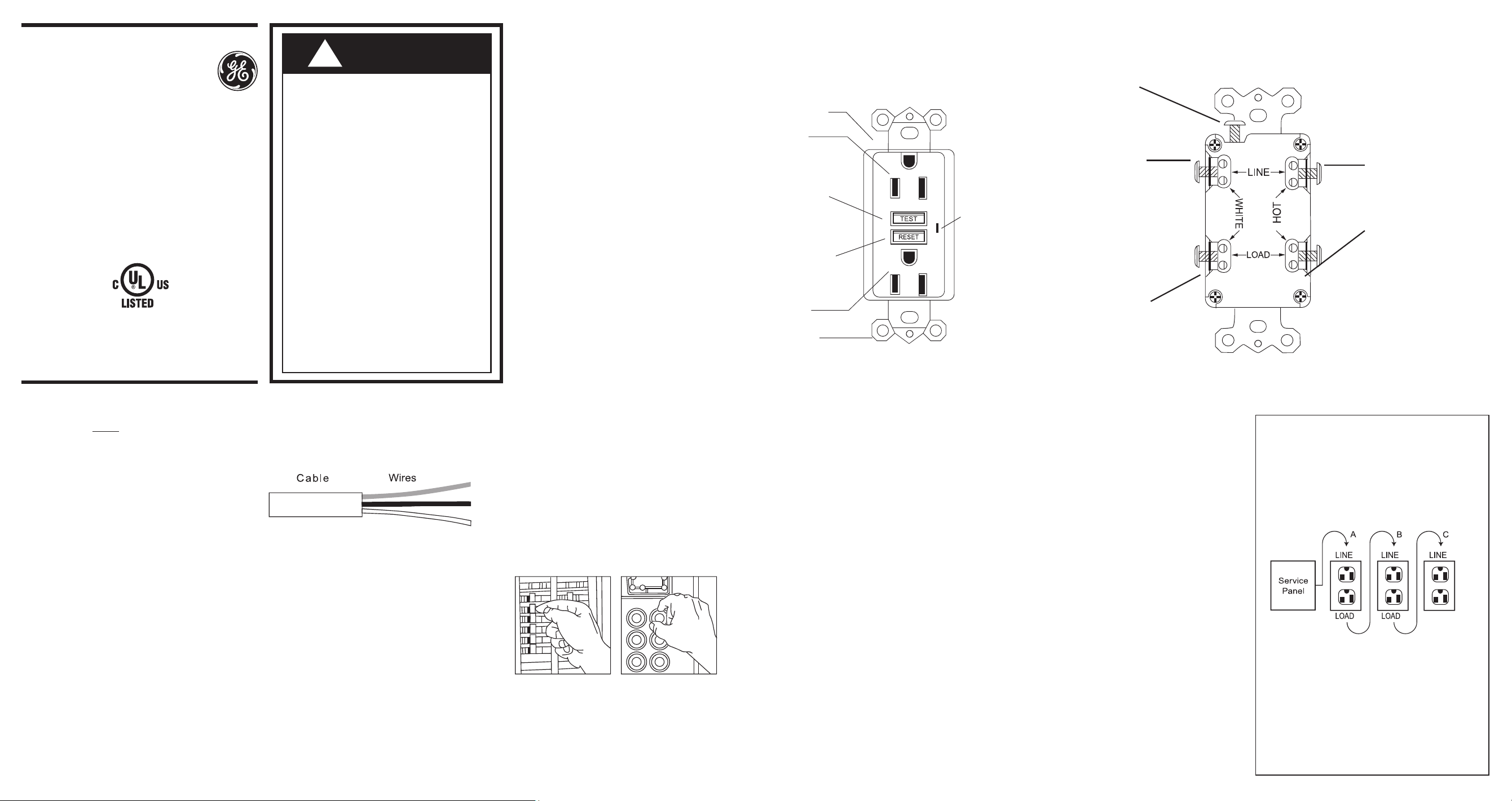
Placement in circuit:
The GFCI’s place in the circuit determines
if it protects other receptacles in the
circuit.
Sample circuit:
Placing the GFCI in position A will
also provide protection to “load side”
receptacles B and C. On the other hand,
placing the GFCI in position C will not
provide protection to receptacles A or B.
Remember that receptacles A, B and C
can be in different rooms.
BACK VIEW
FRONT VIEW
Grounding Terminal (Green):
Connection for bare
copper or green wire
Screw (terminal) colors:
Green = grounding terminal
Silver = white terminals
Brass = hot terminals
LINE
Hot terminal (Brass):
Connection for the
LINE cable's
black wire
LOAD
Hot terminal (Brass):
Connection for the
LOAD cable's
black wire
LINE
White terminal (Silver):
Connection for the LINE
cable's white wire
LOAD
White terminal (Silver):
Connection for the
LOAD cable's white wire
Please read this leaflet completely
before getting started.
Installing and
Testing a GFCI
Receptacle
Ground Fault Receptacle
• To prevent severe shock or electrocution,
always turn the power OFF at the service
panel before working with wiring.
• Use this GFCI receptacle with copper
or copper-clad wire. Do not use it with
aluminum wire.
• Do not install this GFCI receptacle on a
circuit that powers life support equipment
because if the GFCI trips, it will shut down
the equipment.
• For installation in damp or wet locations,
the GFCI receptacle must be listed and
marked as Weather Resistant (WR).
• For installation in wet locations, protect
the GFCI receptacle with a weatherproof
cover that will keep both the receptacle
and any plugs dry.
• Must be installed in accordance with
national and local electrical codes.
CAUTION
!
TEST button:
See Step 8
Receptacle
Outlet
Outlet
Mounting
Bracket
Red
LED
RESET button:
See Step 8
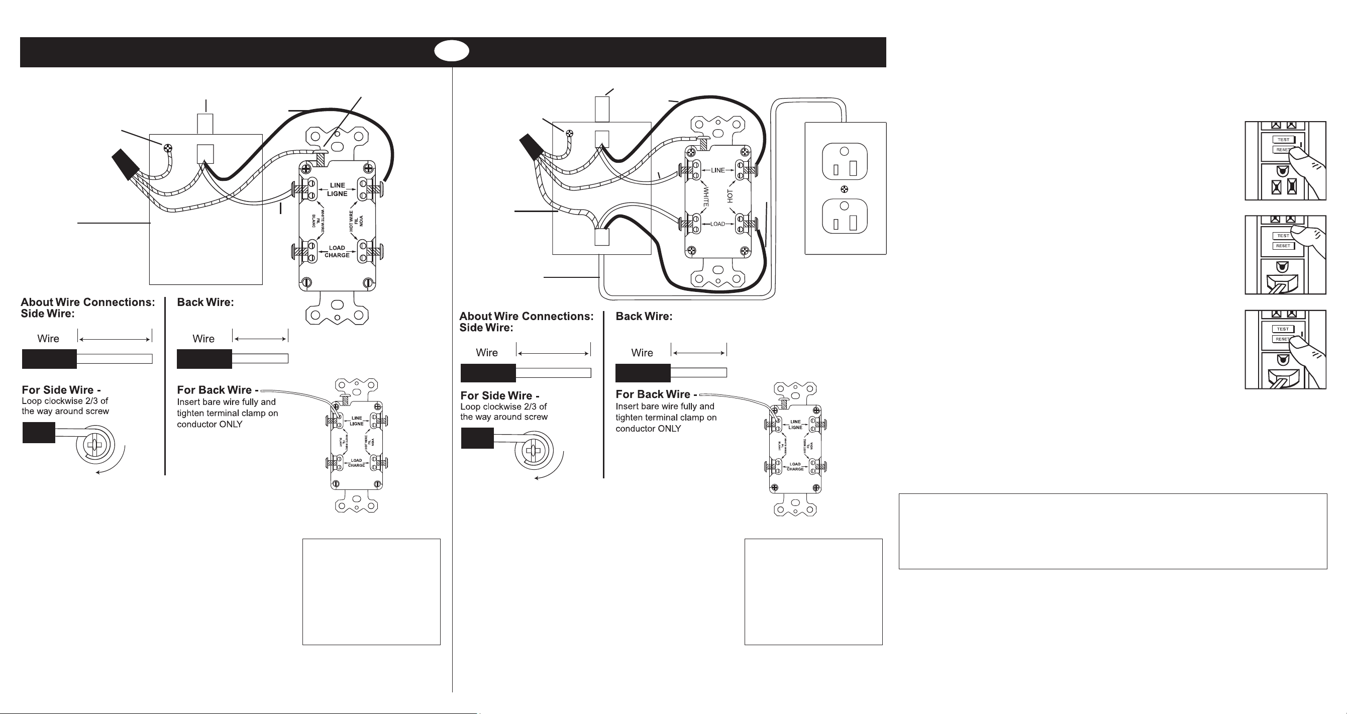
7. Connect the wires (choose A or B) only after reading other side completely
8. Test your work
Why perform this test?
• If you miswired the GFCI, it may not prevent personal injury or death due to a
ground fault (electrical shock).
• If you mistakenly connect the LINE wires to the LOAD terminals, the GFCI cannot be reset
and there is no power output to the receptacle.
Procedure:
(a) This GFCI is shipped from the factory in the tripped condition and can
not be reset until it is wired correctly and power is supplied to the device.
Plug a lamp or radio into the GFCI (and leave it plugged in). Turn the
power ON at the service panel. Press the RESET button. Make sure the
lamp or radio is ON. If the lamp or radio is still OFF or the RESET button
cannot turn the power on, go to Troubleshooting section because the
LINE and LOAD wiring connection have been reversed.
(b) Press the TEST button to trip the device. This should
stop the flow of electricity, making the radio or lamp shut OFF. If the radio
or lamp is on, go to Troubleshooting. If the power goes OFF, you have
installed the GFCI receptacle correctly. To restore power, press the RESET
button.
(c) If you installed your GFCI using Step 7B, plug a lamp or radio into
surrounding receptacles to see which one(s), in addition to the GFCI,
lost power when you pressed the TEST button. DO NOT plug life-saving
devices into any receptacles that lost power. Place a “GFCI PROTECTED”
sticker on every receptacle that lost power.
(d) When Line-Load is miswired, the GFCI cannot be reset and there is no
power output to the receptacle.
(e) The red LED on the faceplate is the indicator of GFCI end-of-life function
test. If the red LED begins to light, it means the GFCI has stopped
functioning and must be replaced immediately.
(f) Press the TEST button (then RESET button) every month to assure proper
operation.
A Self-Test GFCI receptacle has all the features of a conventional GFCI receptacle. In addition,
this receptacle tests itself periodically to confirm the GFCI electronics are functional.
A: One cable (2 or 3 wires) entering the box B: Two cables (4 or 6 wires) entering the box
OR
LINE cable brings
power to the GFCI
LINE cable brings power to the GFCI
Grounding connection
to box (if box has a
grounding terminal)
Grounding
connection to
box (if box has
a grounding
terminal)
Wire
connector
Wire
connector
Electrical
box
Electrical
box
Connect the LINE cable wires to the LINE terminals:
• The white wire connects to the White terminal (Silver).
• The black wire connects to the Hot terminal (Brass).
Connect the grounding wire (only if there is a
grounding wire):
• For a box with no grounding terminal (diagram not shown):
Connect the LINE cable's bare copper (or GREEN) wire
directly to the grounding terminal on the GFCI receptacle.
• For a box with a grounding terminal (diagram shown
above): Connect a 6-inch bare copper (or GREEN) 12 or
14 AWG wire to the grounding terminal on the GFCI. Also
connect a similar wire to the grounding terminal on the
box. Connect the ends of these wires to the LINE cable's
bare copper (or green) wire using a wire connector. If these
wires are already in place, check the connections.
Connect the LINE cable wires to the LINE terminals:
• The white wire connects to the White terminal (Silver).
• The black wire connects to the Hot terminal (Brass).
Connect the LOAD cable wires to the LOAD terminals:
• The white wire connects to the White terminal (Silver).
• The black wire connects to the Hot terminal (Brass).
Connect the grounding wires (only if there is a
grounding wire):
• Connect a 6-inch bare copper (or GREEN) 12 or 14 AWG
wire to the grounding terminal on the GFCI. If the box
has a grounding terminal, also connect a similar wire to
the grounding terminal on the box. Connect the ends of
these wires to the LINE and LOAD cable's bare copper
(or green) wire using a wire connector. If these wires are
already in place, check the connections.
LOAD cable feeds
power to other
receptacle(s)
General Information
GFCI ratings:
GFR4101, GFR4102, GFR4105, GFR4107,
GFR4109, GFR4111
120V AC, 60Hz
15A at outlet, 20A at feed-through
Self-test GFCI
TROUBLESHOOTING
Turn the power OFF and check the wire connection against the appropriate wiring
diagram in Step 7A or 7B. Make sure there are no loose wires or connections. Start the
test from the beginning of Step 8 if you rewired any connections to the GFCI.
HOT
WHITE
WHITE
HOT
HOT
GROUNDING
WIRE
MADE IN CHINA
GE is a trademark of General Electric Company and is
under license by Jasco Products Company LLC, 10 E.
Memorial Rd., Oklahoma City, OK 73114.
This Jasco product comes with a 2-year limited warranty.
Visit www.byjasco.com for warranty details.
Questions? Contact us at 1-800-654-8483 between
7:00AM—8:00PM CST.
32073, 32074, 32075, 32076, 40687 V.5 5/18
Complete the installation:
Fold the wires into the box,
keeping the grounding wire
away from the WHITE and
HOT terminals. Screw the
receptacle to the box and
attach the faceplate.
• Go to Step 8.
Complete the installation:
Fold the wires into the box,
keeping the grounding wire
away from the WHITE and
HOT terminals. Screw the
receptacle to the box and
attach the faceplate.
• Go to Step 8.
1" (2.5cm)
1" (2.5cm)
1/2" (1.3cm)
1/2" (1.3cm)