

Self-service Repair Manual for vivo Y04&Y29s 5G
Contents
1 About this manual .......................................................................................................................................................... 2
1.1 Purpose ................................................................................................................................................................... 2
1.2 Caution .................................................................................................................................................................... 2
1.2.1 Repair notes ..................................................................................................................................................... 2
1.2.2 ESD precautions ............................................................................................................................................... 3
2 Warranty ........................................................................................................................................................................ 3
3 Tools ............................................................................................................................................................................... 3
3.1 Hardware tools ........................................................................................................................................................ 3
3.2 Software update and software tools (to be confirmed after software release) ............................................... 5
4 Repair guide ................................................................................................................................................................... 8
4.1 Spare parts .............................................................................................................................................................. 8
4.2 Device breakdown ................................................................................................................................................. 10
4.3 Disassembly and assembly guide .......................................................................................................................... 11
4.3.1 Replace the Battery Cover .............................................................................................................................. 11
4.3.2 Replace the middle frame ............................................................................................................................. 14
4.3.3 Replace the M board bracket ...................................................................................................................... 17
4.3.4 Replace the lower speaker ........................................................................................................................... 18
4.3.5 Replace the ANA board (incl. the main mic and charging port) .............................................................. 19
4.3.6 Replace the M board .................................................................................................................................... 21
4.3.7 Replace the upper speaker .......................................................................................................................... 23
4.3.8 Replace the battery ........................................................................................................................................ 24
4.3.9 Replace the display assembly ...................................................................................................................... 27
4.3.10 Replace the side buttons ........................................................................................................................... 28
4.3.11 Replace the display module ...................................................................................................................... 29

1 About this manual
1.1 Purpose
This manual is intended to guide DIY hobbyists with certain hands-on skills and repair experience in replacing official
components of vivo phones.
1.2 Caution
All features, characteristics, specifications, and other device information provided in this manual, including but not
limited to device advantages, design, pricing, components, performance, availability, and functionality, are subject to
change without prior notice. vivo reserves the right to modify this manual or any descriptions herein at any time
without the obligation to give notice of such modifications. Please read through this manual carefully before repair. If
you do not meet the repair conditions, do not disassemble the device. You may visit a vivo customer service center for
repairs.
1.2.1 Repair notes
Warning: Failure to follow the instructions herein or the use of non-official vivo components or improper tools may
damage the device, its components, or other property; impair device functionality and water resistance; and in severe
cases, cause fires or other safety hazards, leading to personal injury or death.
(1) vivo assumes no liability for any damage or defects resulting from repairs made by unauthorized carriers, yourself,
or other non-professionals. vivo is not responsible for any device damage, personal injury, or other safety
consequences caused by failure to follow this manual.
(2) Any damage or defects resulting from attempts to repair the device by anyone other than a vivo-certified service
provider are not covered by the warranty.
(3) We recommend that you use only official tools for repairing. Most electronic components are sensitive to
electromagnetic forces, and low-quality tools may easily damage your device. For tool details, see Section 3.1.
(4) We recommend that you use only official spare parts. Third-party spare parts may not function properly and may
cause fires or personal injury.
(5) Some components, such as laser focusing/proximity/fingerprint sensors, rear cameras, touchscreen panels, and
speakers, may require calibration to ensure their performance after repair.
(6) The water and dust resistance of a device repaired by yourself or other non-professionals cannot be guaranteed.
(7) If you need to access device fault data or obtain more detailed diagnostics, please visit a vivo customer service
center.
(8) If you need to replace components that are unavailable on the market, please visit a vivo customer service center
for further assistance.
(9) Before making repairs, back up important data stored in the device.
(10) Before making repairs, wear proper safety gear. vivo is not responsible for any injury due to failure to wear proper
safety gear. For details of the required disassembly and assembly tools, see Section 3.1.
(11) Make repairs in a safe location.
(12) Before making repairs, make sure that the device is powered off and its battery is fully discharged.
(13) If the device is damaged, emits smoke, or produces a burning smell, stop repairing it immediately and contact vivo
customer service. If a fire is started, extinguish it with a carbon dioxide or dry powder fire extinguisher, specialized
foam, sand, soil, gravel, or a dedicated lithium-ion battery fire suppressant.
(14) When repairing the device, wear protective gear such as safety goggles, gloves, and masks.
(15) When removing the back cover, take care not to damage the device. Before reassembling the device, make sure
that no free screws or foreign objects are left around the battery.
(16) During reassembly, inspect the back cover for abnormalities before reinstalling it. Avoid impact or pressure on the
battery to prevent damage. If the battery is damaged, please visit a vivo customer service center.
1.2.2 ESD precautions
Electrostatic discharge (ESD) is a sudden flow of electric current between two charged objects due to contact, a short
circuit, or dielectric breakdown. ESD negatively affects mobile devices, particularly their electronic components.
(1) We recommend that you wear anti-static wrist straps and gloves, and use anti-static mats when you repair the
device.
(2) Increase airflow in the work area to reduce the likelihood of accidental ESD. In an environment with low humidity,
such as an air-conditioned room, ESD is more likely to happen.
2 Warranty
2.1 A 90-day warranty is provided for official spare parts. If any quality issues arise with them within that period, you
may contact vivo for a replacement.
2.2 A device repaired by anyone other than a vivo-authorized service provider is not covered by the warranty, and you
will bear the repair costs.
2.3 Any damage caused during self-service repairs will be your responsibility.
3 Tools
3.1 Hardware tools
Tool name
Photo
Usage
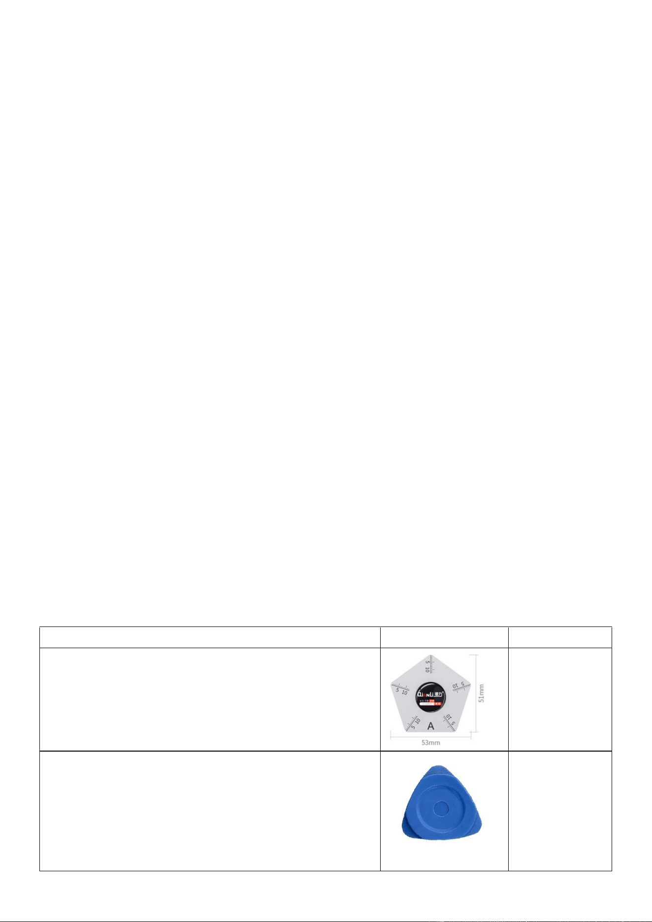
Metal pry pick (with a scale)
Disassembling the
display module
triangular prying pick
Remove the
middle frame
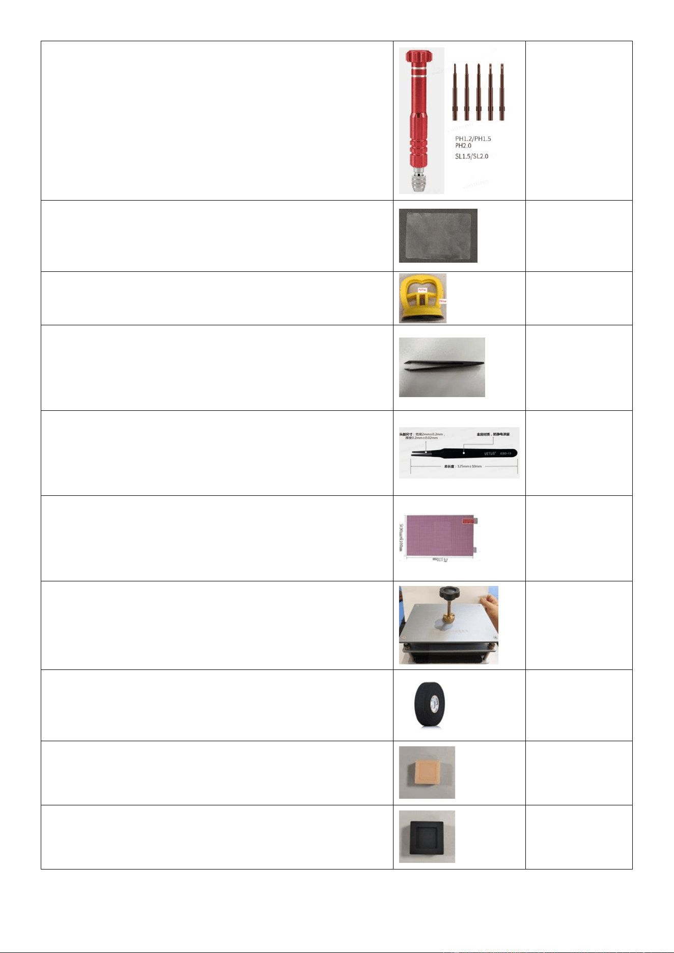
Screwdriver kit (rubber-grip dual-purpose screwdriver, 6 × 100 mm)
Removing and
installing screws
PET pry sheet
Removing the
back cover and
display module
Suction cup
Removing the
back cover
Anti-static carbon fiber tweezers (with pointed tips)
Removing board-
to-board (BTB)
and coaxial cable
connectors
Metal flat-head tweezers
Removing the M
board and ANA
board, or cleaning
adhesive
Anti-shatter film
Preventing glass
shattering on
screen / back
cover
Universal pressure fixture
Securing the
screen or back
cover
Electrical insulation tape, 3M, black, 17 mm
Optical calibration
False finger, flesh-colored, 20 × 20 × 12 mm
Testing electro-
optical fingerprint
recognition
False finger, black, 22 × 22 × 12 mm
Testing electro-
optical fingerprint
recognition
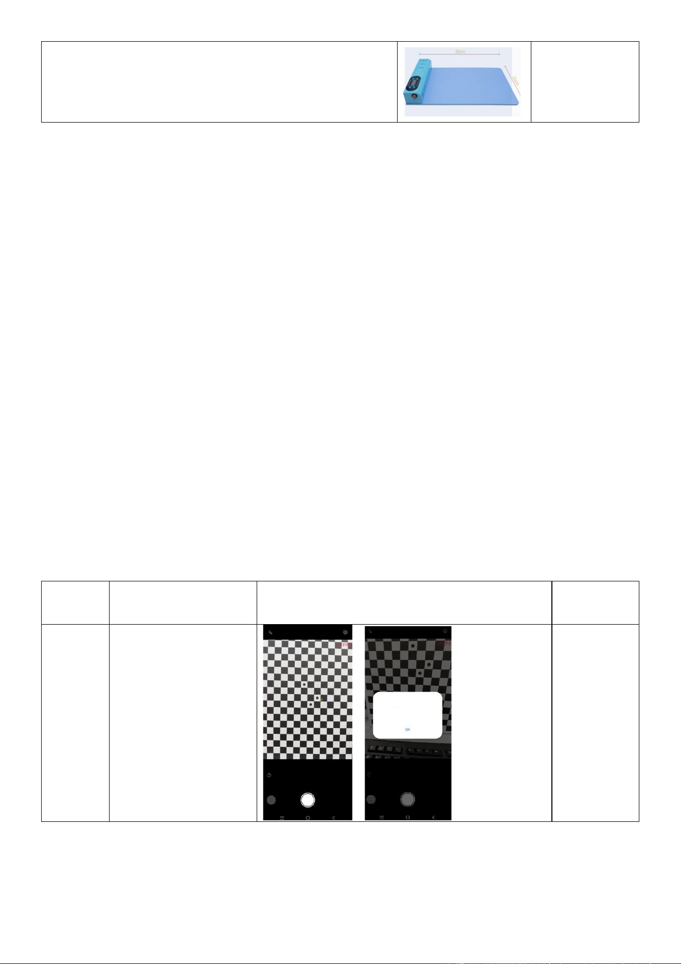
Heating pad (default temperature: 65°C)
Heating the back
cover and screen
3.1.1 Tool purchase
Official purchase link: https://www.vivo.com/eu/view/support/aboutSelfServiceRepair?code=selfServiceRepair
3.2 Software update and software tools (to be confirmed after software release)
3.2.1 Software update via FOTA
⚫ To update software, go to Settings > System Update.
⚫ If the system is already of the latest version, no update is needed.
⚫ If a software update is available, you can set the time for automatic update.
Note:
1. Updating software via mobile data may incur additional fees.
2. If the latest software has been downloaded to the device, these options do not take effect.
3.2.2 Self-diagnosis
Before and after repair, perform a self-diagnosis to check if the device functions properly.
Open the vivo Store / vivo.com app, go to Support > Hardware Test > Self-calibration, and enter the calibration code
"SELFREPAIR" to perform the check.
3.2.3 Self-calibration on the vivo Store / vivo.com app
You can perform calibration after replacing the display or camera, such as the calibration of the rear cameras (for
devices with two or more rear cameras), in-display fingerprint scanner, infrared proximity sensor, and ambient light
sensor. The calibration ensures proper functionality of components after repairs.
The following table describes calibration items and instructions.
Calibration
item
Instruction
Illustration
Description
Rear
cameras
Open the vivo Store /
vivo.com app, go to
Support > Hardware Test >
Self-calibration, enter the
calibration code
"SELFREPAIR", tap Rear
dual-camera calibration,
and calibrate the cameras.
This
calibration is
required after
M board
disassembly
or
replacement
of any rear
camera.
Camera Calibration Successful
The calibration was successful. Restart
the phone.
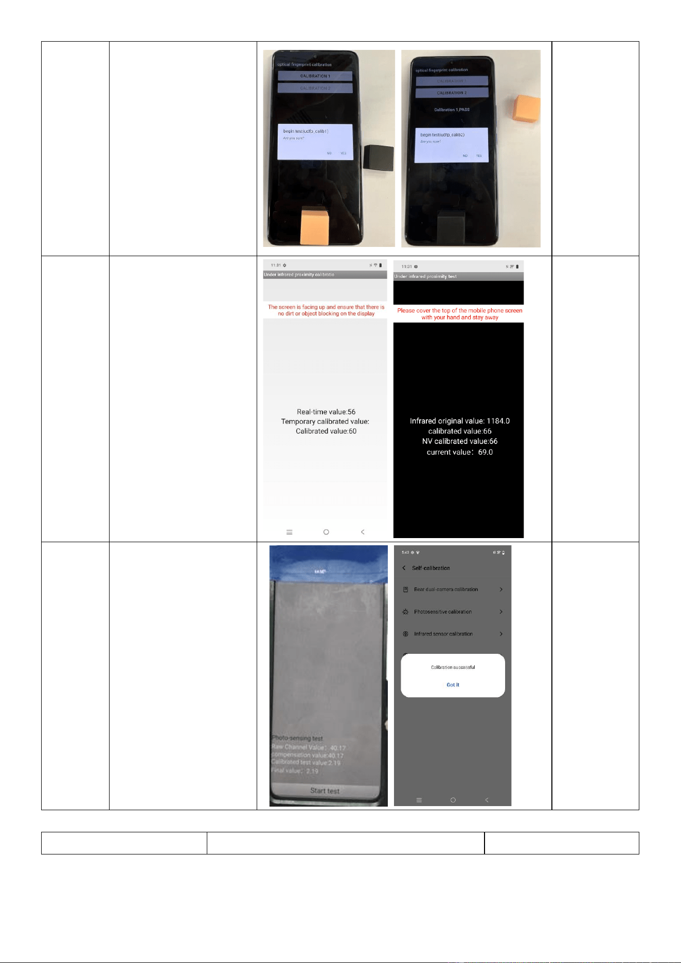
In-display
fingerprint
scanner
Open the vivo Store /
vivo.com app, go to
Support > Hardware Test >
Self-calibration, enter the
calibration code
"SELFREPAIR", tap Screen
finger calibration, and
calibrate the fingerprint
scanner.
This
calibration is
required after
replacement
of the display
assembly,
display
module, or
fingerprint
module.
Infrared
proximity
sensor
Open the vivo Store /
vivo.com app, go to
Support > Hardware Test >
Self-calibration, enter the
calibration code
"SELFREPAIR", tap Infrared
proximity sensor
calibration, and calibrate
the infrared proximity
sensor.
This
calibration is
required after
M board
disassembly
or
replacement
of the display
assembly or
display
module.
Ambient
light
sensor
Open the vivo Store /
vivo.com app, go to
Support > Hardware Test >
Self-calibration, enter the
calibration code
"SELFREPAIR", tap
Photosensitive calibration,
and calibrate the ambient
light sensor.
This
calibration is
required after
M board
disassembly
or
replacement
of the display
assembly or
display
module.
3.3 Protective tools
Tool name
Photo
Usage
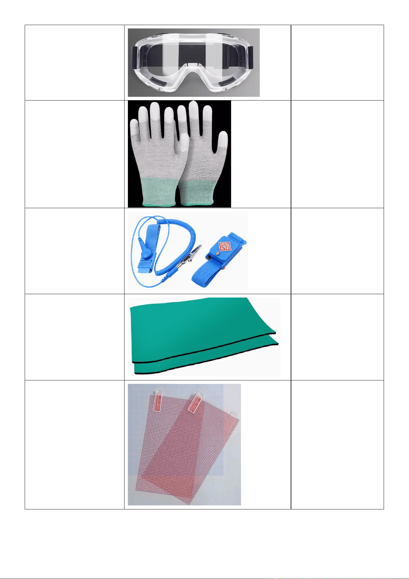
Safety goggles
Preventing liquid/splinter
splashes from hurting your
eyes during repairs
Anti-static cut-resistant gloves
Preventing ESD damage
and cuts during repairs
Anti-static wrist strap
Preventing ESD damage to
the device during repairs
Anti-static mat
Preventing ESD damage to
the device during repairs
Anti-shatter film
Preventing device damage
or personal injury due to
screen or back cover
shattering
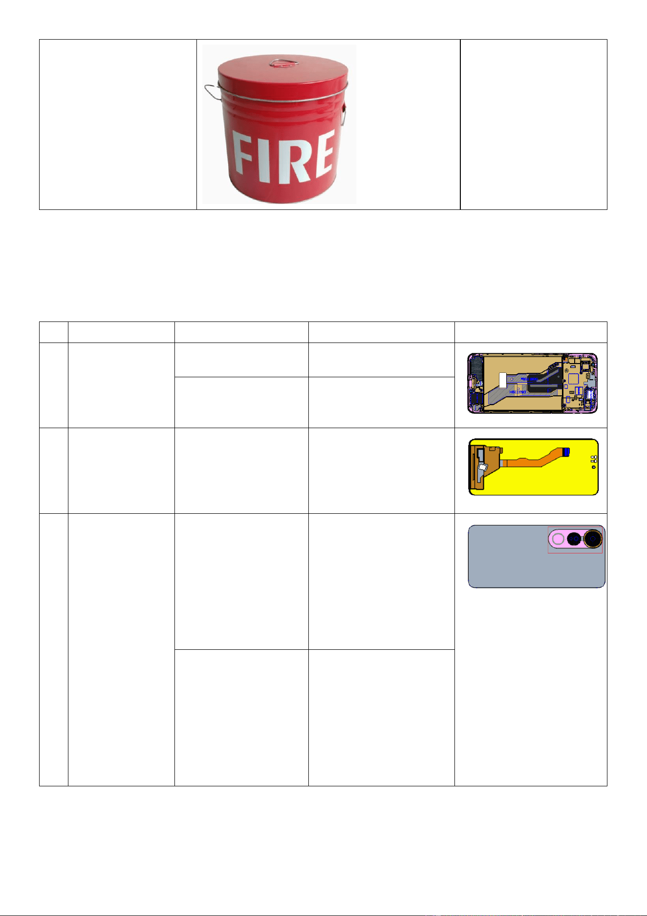
Fire bucket
Containing a burning
battery
Note: vivo does not provide all protective tools. You need to purchase them from other sources.
4 Repair guide
4.1 Spare parts
No.
Material name
Purchase code
Adaptation project
Illustration
1
Display assembly
5437461
V50 Lite
5437416
V50 Lite 5G
2
Display module
5436770
V50 Lite & V50 Lite 5G
3
Back cover
assembly
5437457(Black/EEA)
5437458(Purple/EEA)
5437459(Black/AT)
5437460(Purple/AT)
V50 Lite
5437414(Black/EEA)
5437415(Gold/EEA)
5437420(Black/AT)
5437421(Gold/AT)
V50 Lite 5G
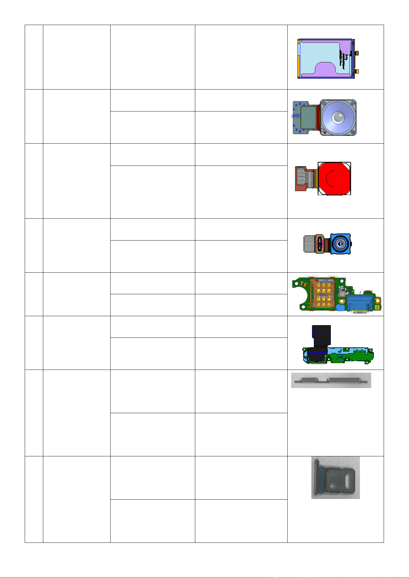
4
Battery assembly
5437406(EEA)
5437407(AT)
V50 Lite & V50 Lite 5G
5
Rear Secondary
Camera assembly
5437453
V50 Lite
5437410
V50 Lite 5G
6
Rear main camera
5437452
V50 Lite
5437409
V50 Lite 5G
7
Front camera
5437451
V50 Lite
5437408
V50 Lite 5G
8
ANA board
4935291
V50 Lite
4935288
V50 Lite 5G
9
Speaker
5437456
V50 Lite
5437413
V50 Lite 5G
10
Side buttons
5437454(Black)
5437455(Purple)
V50 Lite
5437411(Black)
5437412(Gold)
V50 Lite 5G
11
Card tray
5437462(Black)
5437463(Purple)
V50 Lite
5437417(Black)
5437418(Gold)
V50 Lite 5G
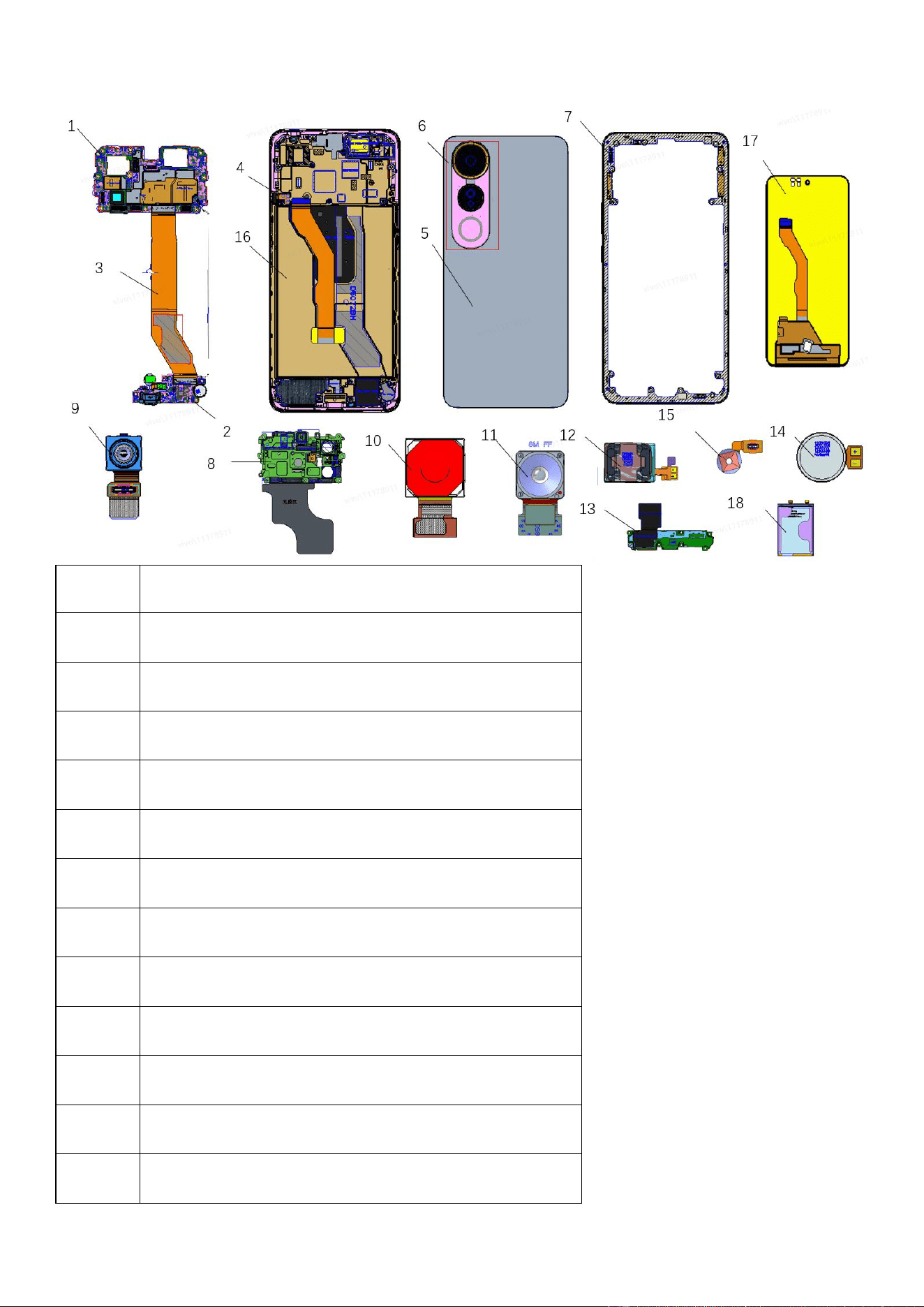
4.2 Device breakdown
No.
Material name
1
M Board
2
ANA Board
3
FMA Board
4
FK Board
5
Back cover assembly
6
Camera Glass Cover With Decorative Ring
7
Middle Cover assembly
8
M board bracket assembly
9
Front camera assembly
10
Rear main camera assembly
11
Rear Secondary Camera assembly
12
Receiver Component
13
Speaker Component
14
Motor assembly
15
Fingerprint Module assembly
16
Display assembly
17
Display module
18
Battery assembly
4.3 Disassembly and assembly guide
➢ Perform the following steps before starting the repair:
➢ Back up your data.
➢ Fully discharge the battery.
➢ Power off the phone and disconnect all external data cables.
➢ Wear anti-static gloves.
➢ If you find issues such as cosmetic damage and adhesive overflow after assembly, you may visit a vivo official
service center.
The disassemble and assemble video please refer to:
https://www.tiktok.com/@vivocare_global/video/7516457382931680542?is_from_webapp=1&sender_device=pc
4.3.1 Replace the Battery Cover
Repair Difficulty: Low
Estimated Time: 6–10 minutes
Required Spare Parts: Battery cover assembly
Disassembly
Operation
Illustration
Remarks
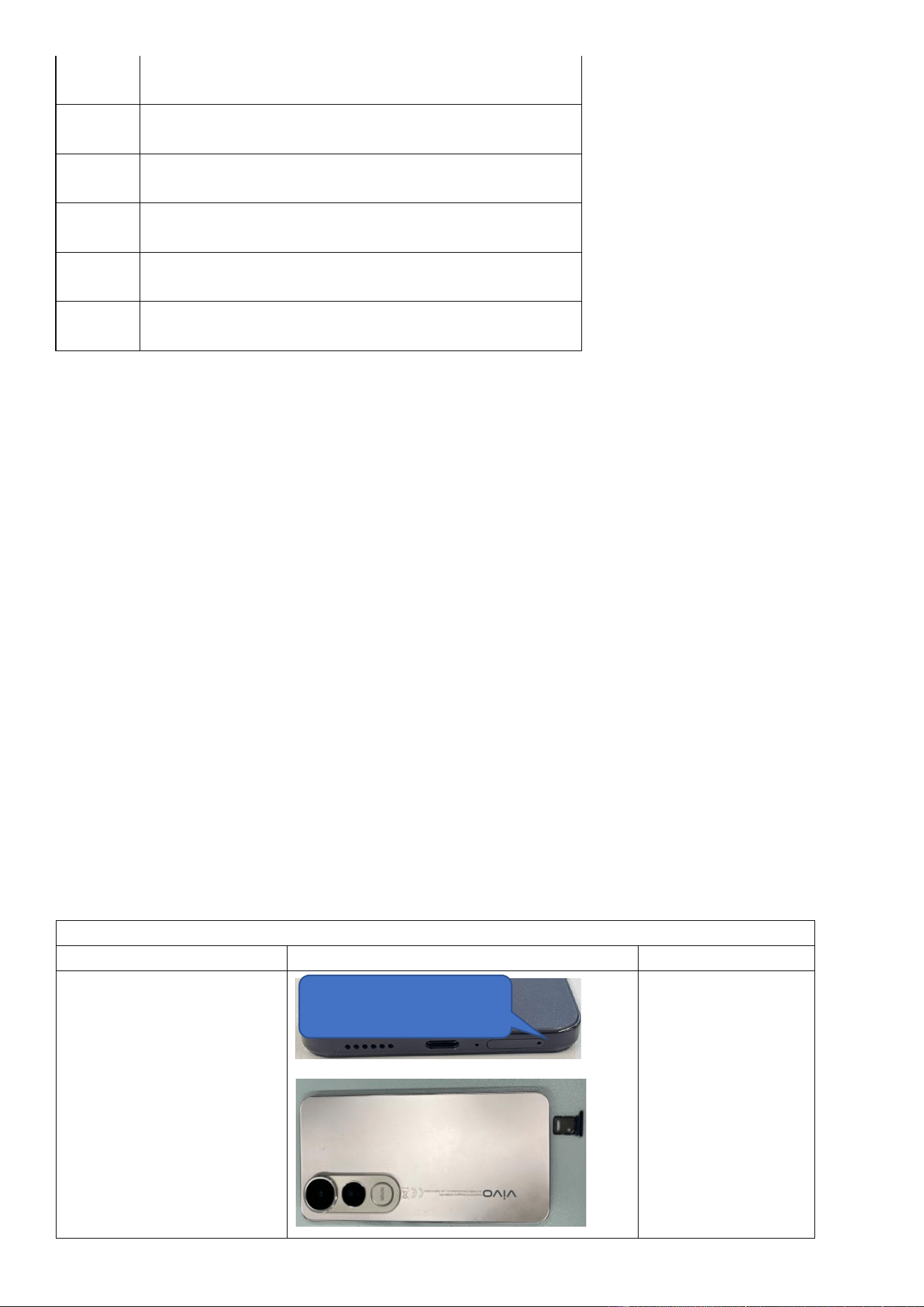
Step 1: Power off the device.
Insert a SIM card tray eject tool
into the eject hole to remove
the SIM card tray.
Insert the SIM card tray eject tool at
this position to remove the SIM card
tray
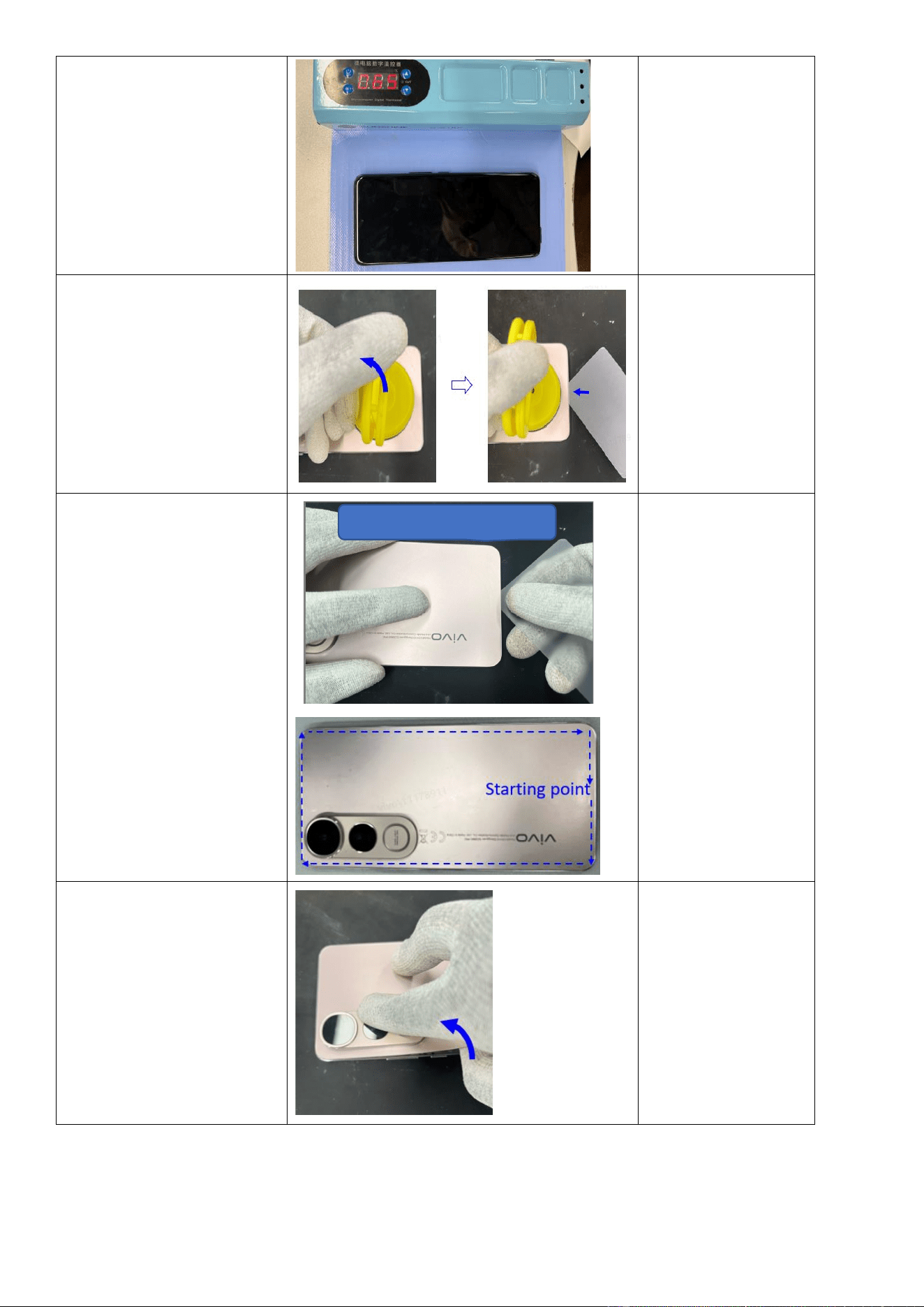
Step 2: Use a heating pad set to
65℃ to heat the phone for 5
minutes.
The heating pad defaults to
a preset temperature of
65℃. If you need to adjust
the temperature, please
refer to the device's
manual.
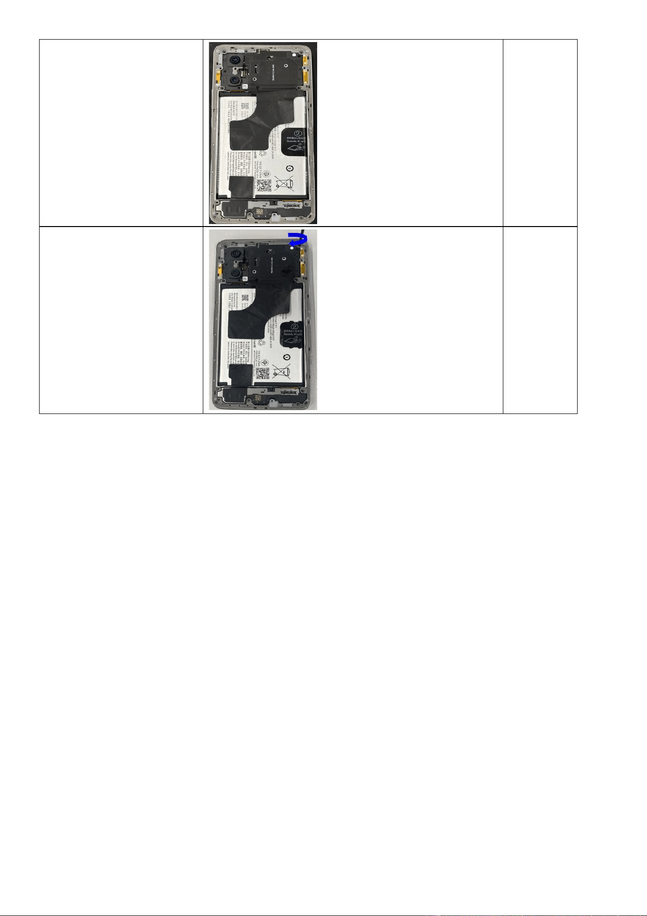
Step 3: Place a suction cup on
the bottom center edge of the
battery cover, lift upwards to
create a gap, and then insert a
prying pick into the gap.
Notes:
1. Exercise caution when
using a handled
suction cup to avoid
injury, as the handle
may detach during
use.
2. Do not insert the
prying pick more than 5
mm into the device.
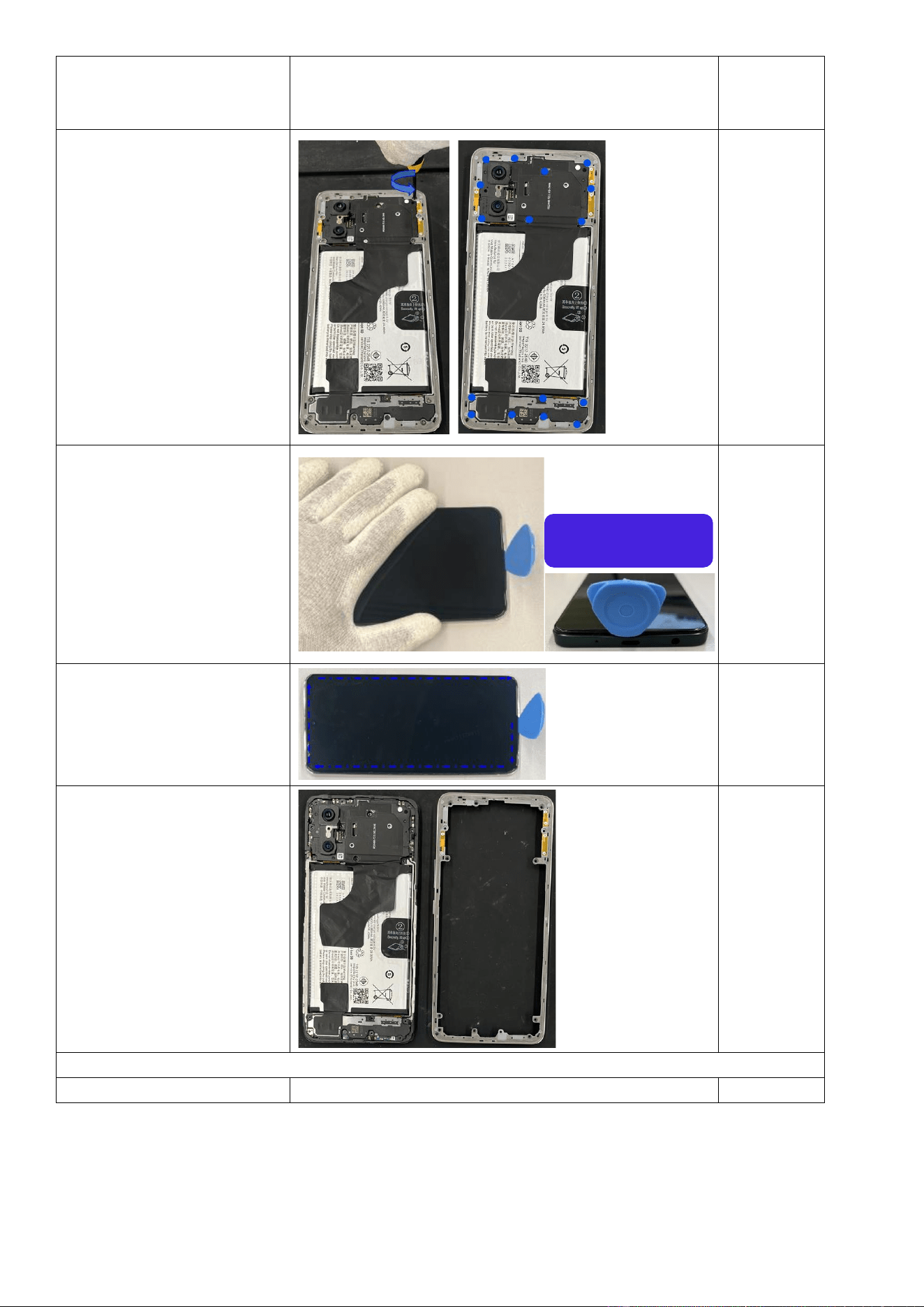
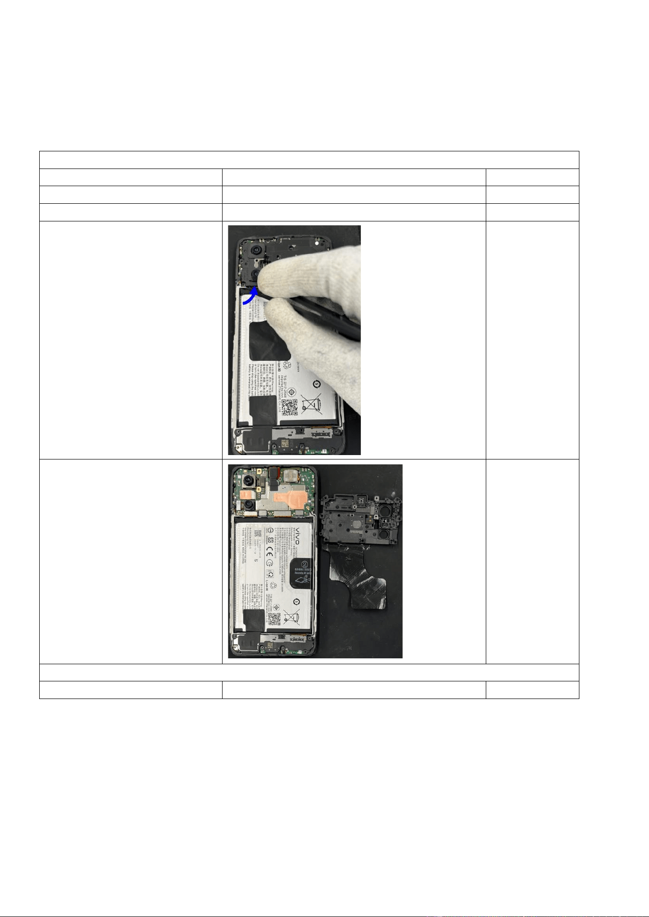
Step 4: Use the prying pick to
cut along the battery cover
clockwise as illustrated in the
picture.
Step 5: Once the edges are cut
open, gently lift the battery
cover from the position shown
in the picture.
Cut along the battery cover clockwise
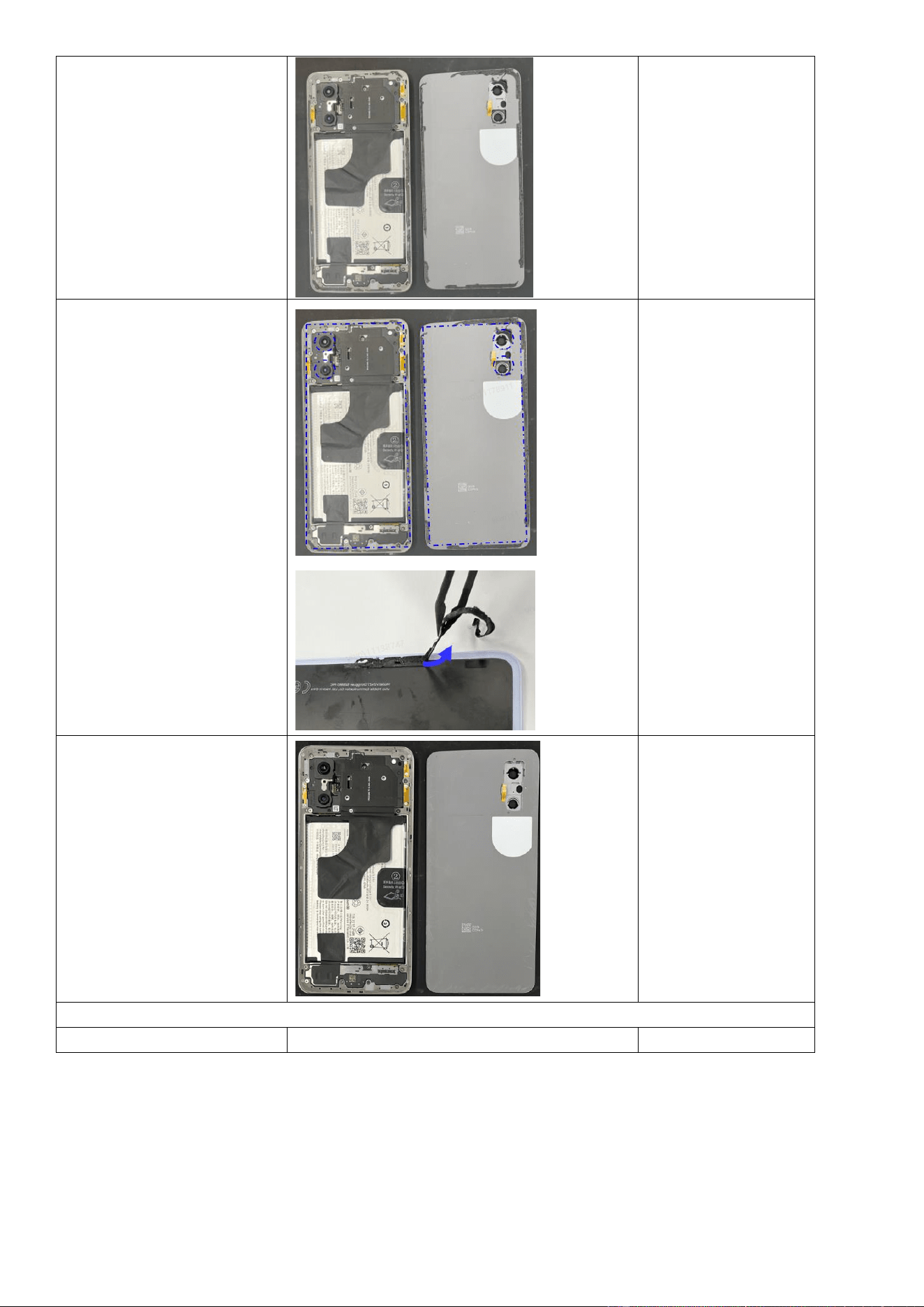
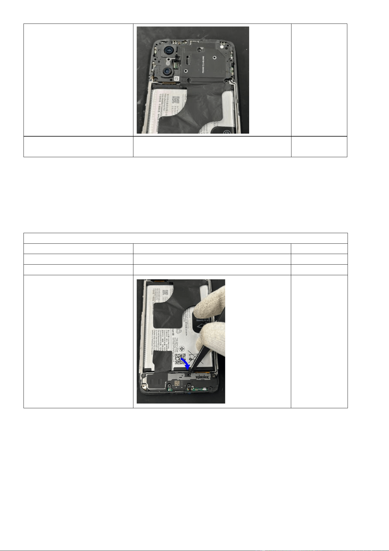
Step 6: Separate the battery
cover to complete the removal.
Step 7: Use pointed anti-static
tweezers to remove all residual
adhesive from the battery
cover and the back of the
device.
Do not to touch the rear
cameras or the lens of the
battery cover with your
fingers or any foreign
objects, and avoid damaging
nearby components.
Step 8: Clean residual adhesive
thoroughly.
Assembly
Operation
Illustration
Remarks
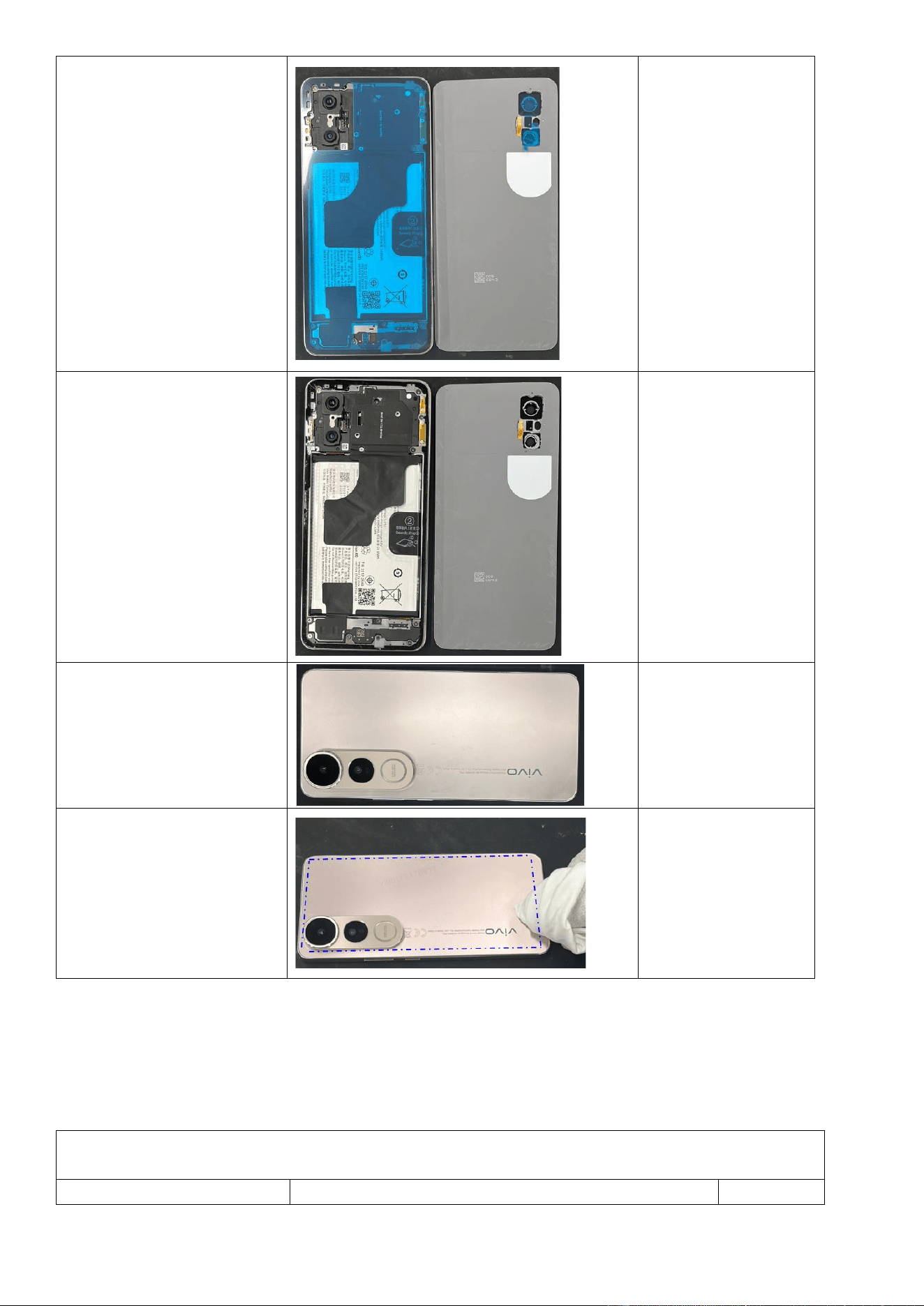
Step 1: Apply double-sided
tape to the main camera seal,
mainboard bracket seal, and
battery cover.
Step 2: Remove the release
films from the main camera seal,
mainboard bracket seal, and
battery cover.
Step 3: Align the battery cover
with the frame and press it into
place.
Step 4: Wrap a lint-free cloth
around your finger and press
over the adhesive areas to
activate the adhesive,
completing the battery cover
installation.
4.3.2 Replace the middle frame
Repair Difficulty: Low
Estimated Time: 8–12 minutes
Required Spare Parts: Middle Frame assembly
Disassembly
Operation
Illustration
Remarks
Step 1: Remove the battery
cover (refer to the battery cover
removal steps).
Refer to the installation steps in section 4.3.1.
Step 2: Use a Phillips
screwdriver to remove the 16
mainboard bracket screws as
illustrated.
Step 3: After removing the
screws, insert a triangular
prying pick at the location of
the USB port at the bottom of
the device.
Step 4: Slide the prying pick
clockwise around the device to
detach the frame as illustrated.
Step5: The removal of the
middle frame is now complete.
Installation
Operation
Illustration
Remarks
Disassemble from the USB port
area
Step 1: Install the middle frame
assembly. Press the frame
clockwise to ensure full
engagement.
Step 2: Insert and tighten all 16
screws to complete the
reinstallation of the frame.
4.3.3 Replace the M board bracket
Difficulty: low
Duration: 8–12 minutes
Required spare parts: M board bracket assembly
Disassembly
Operation
Illustration
Remarks
Step 1: Remove the back cover.
See Section 4.3.1.
Step 2: Remove the middle frame.
See Section 4.3.2.
Step 3: Use anti-static tweezers to
lift the M board bracket from the
indicated position.
Step 4: Remove the M board
bracket.
Assembly
Operation
Illustration
Remarks
Step 1: Secure the M board bracket
over the M board and press it firmly
into position.
Check for any
camera module
misalignment.
Step 2: Install the middle frame and
fasten it with 16 screws.
See Section 4.3.2.
4.3.4 Replace the lower speaker
Difficulty: low
Duration: 8–12 minutes
Required spare parts: lower speaker assembly
Disassembly
Operation
Illustration
Remarks
Step 1: Remove the back cover.
See Section 4.3.1.
Step 2: Remove the middle frame.
See Section 4.3.2.
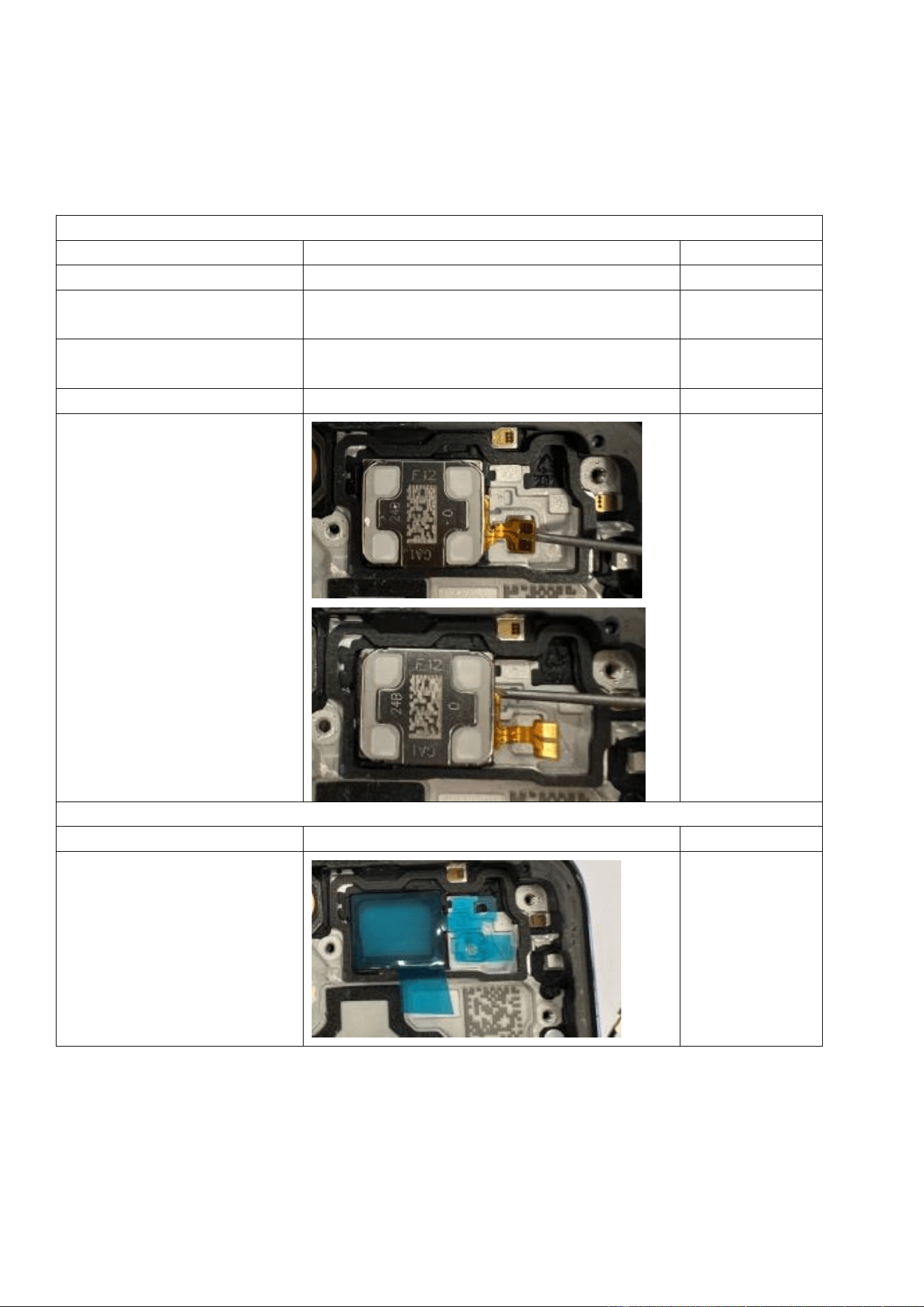
Step 3: Use pointed tweezers to lift
the lower speaker from the
indicated position.
Step 4: Remove the lower speaker.
Assembly
Operation
Illustration
Remarks
Step 1: Before installation, check
the speaker for attached foreign
objects. Then, mount the speaker
to the indicated position of the
main upper part.
Step 2: Make sure that the speaker
lies flat without lifting.
Step 3: Install the middle frame and
fasten it with screws.
See Section 4.3.2.
4.3.5 Replace the ANA board (incl. the main mic and charging port)
Difficulty: low
Duration: 9–13 minutes
Required spare parts: ANA board assembly
Disassembly
Operation
Illustration
Remarks
Step 1: Remove the back
cover.
See Section 4.3.1.
Step 2: Remove the middle
frame.
See Section 4.3.2.
Step 3: Remove the lower
speaker.
See Section 4.3.4.
Step 4: Disconnect the BTB
connectors and coaxial cable
from the indicated
positions.
Step 5: Use pointed
tweezers to lift the ANA
board from the indicated
position.
Assembly
Operation
Illustration
Remarks
Step 1: Align the bottom
edge of the ANA board with
the USB port, and then press
the board until it lies flat
without lifting.
Step 2: Connect the coaxial
cable and neatly route the
coaxial cable into the cable
slot.
Step 3: Connect the BTB
connectors of the display
and fingerprint scanner.
Step 4: Install the middle
frame and fasten it with
screws.
See Section 4.3.2.
4.3.6 Replace the M board
Difficulty: low
Duration: 9–12 minutes
Required spare parts: M board
Disassembly
Operation
Illustration
Remarks
Step 1: Remove the back
cover.
See Section 4.3.1.
Step 2: Remove the middle
frame.
See Section 4.3.2.
Step 3: Remove the M board
bracket.
See Section 4.3.3.
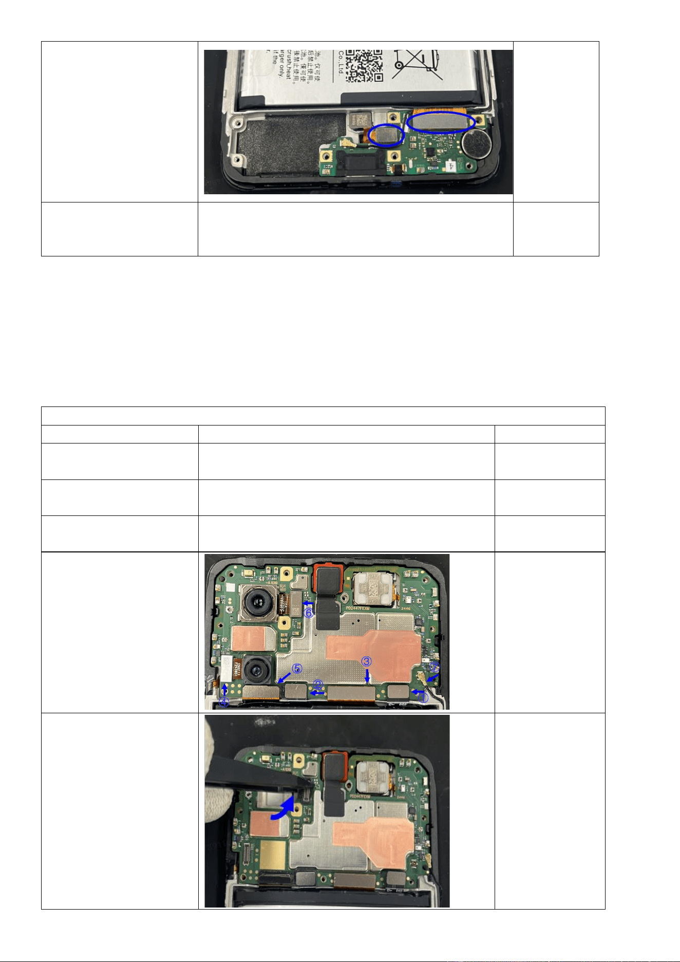
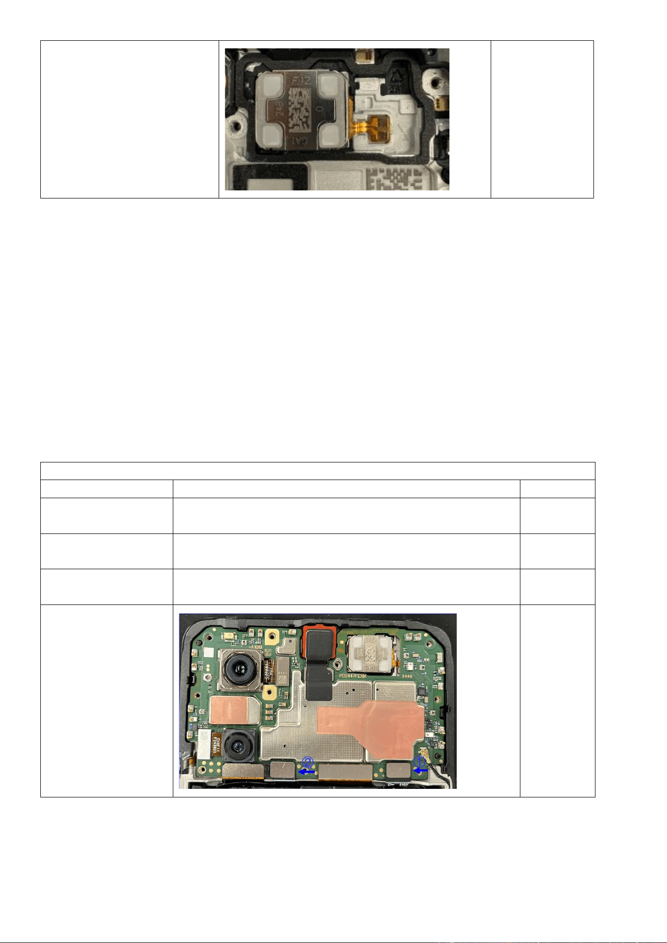
Step 4: Use pointed anti-
static tweezers to
disconnect BTB connectors
and/or coaxial cables of the
battery and other
components.
After the camera is
removed, protect it
from dust and
contamination.
Avoid touching the
lens to prevent
impact on photo
quality.
Step 5: Use pointed anti-
static tweezers to pry up the
M board from the indicated
position.
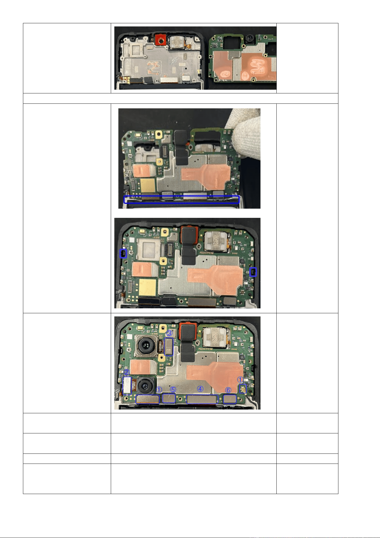
Step 6: Remove the M
board.
Assembly
Step 1: Align the bottom
edge of the M board with
the main upper part, and
then secure the M board.
Make sure that the board
lies flat without lifting, and
snap-fits are engaged in
place.
Step 2: Install the camera,
and all BTB connectors and
coaxial cables in the
indicated order.
Step 3: Install the M board
bracket.
See Section 4.3.3.
Step 4: Install the middle
frame.
See Section 4.3.2.
Step 5: Install the back cover.
See Section 4.3.1.
Step 6: Perform calibrations.
After assembly, calibrate the rear cameras, ambient light
sensor, and infrared proximity sensor as specified in
Section 3.2.3.
4.3.7 Replace the upper speaker
Difficulty: low
Duration: 9–12 minutes
Required spare parts: upper speaker assembly
Disassembly
Operation
Illustration
Remarks
Step 1: Remove the back cover.
See Section 4.3.1.
Step 2: Remove the middle
frame.
See Section 4.3.2.
Step 3: Remove the M board
bracket.
See Section 4.3.3.
Step 4: Remove the M board.
See Section 4.3.6.
Step 5: Use a flat-head
screwdriver to detach the
speaker reinforcement plate, and
then remove the upper speaker
unit.
When removing
the speaker unit,
do not insert the
screwdriver too
deeply to avoid
damaging the
display.
Assembly
Operation
Illustration
Remarks
Step 1: Clean residual adhesive
from the upper speaker area.
Apply a new adhesive tape to
secure the upper speaker to the
middle frame and remove the
blue release liner.
Avoid damaging
the display during
adhesive removal.
Step 2: Press the speaker to
position on the main upper part.
4.3.8 Replace the battery
Difficulty: low
Duration: 6–10 minutes
Required spare parts: battery assembly
Before you remove the battery:
1. Fully discharge the battery.
2. Prepare a fire bucket in case of a battery fire.
Disassembly
Operation
Illustration
Remarks
Step 1: Remove the
back cover.
See Section 4.3.1.
Step 2: Remove the
middle frame.
See Section 4.3.2.
Step 3: Remove the M
board bracket.
See Section 4.3.3.
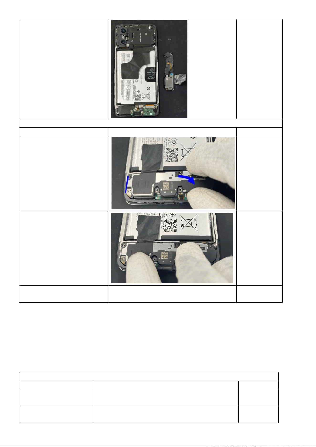
Step 3: Disconnect
the BTB connector of
the battery.
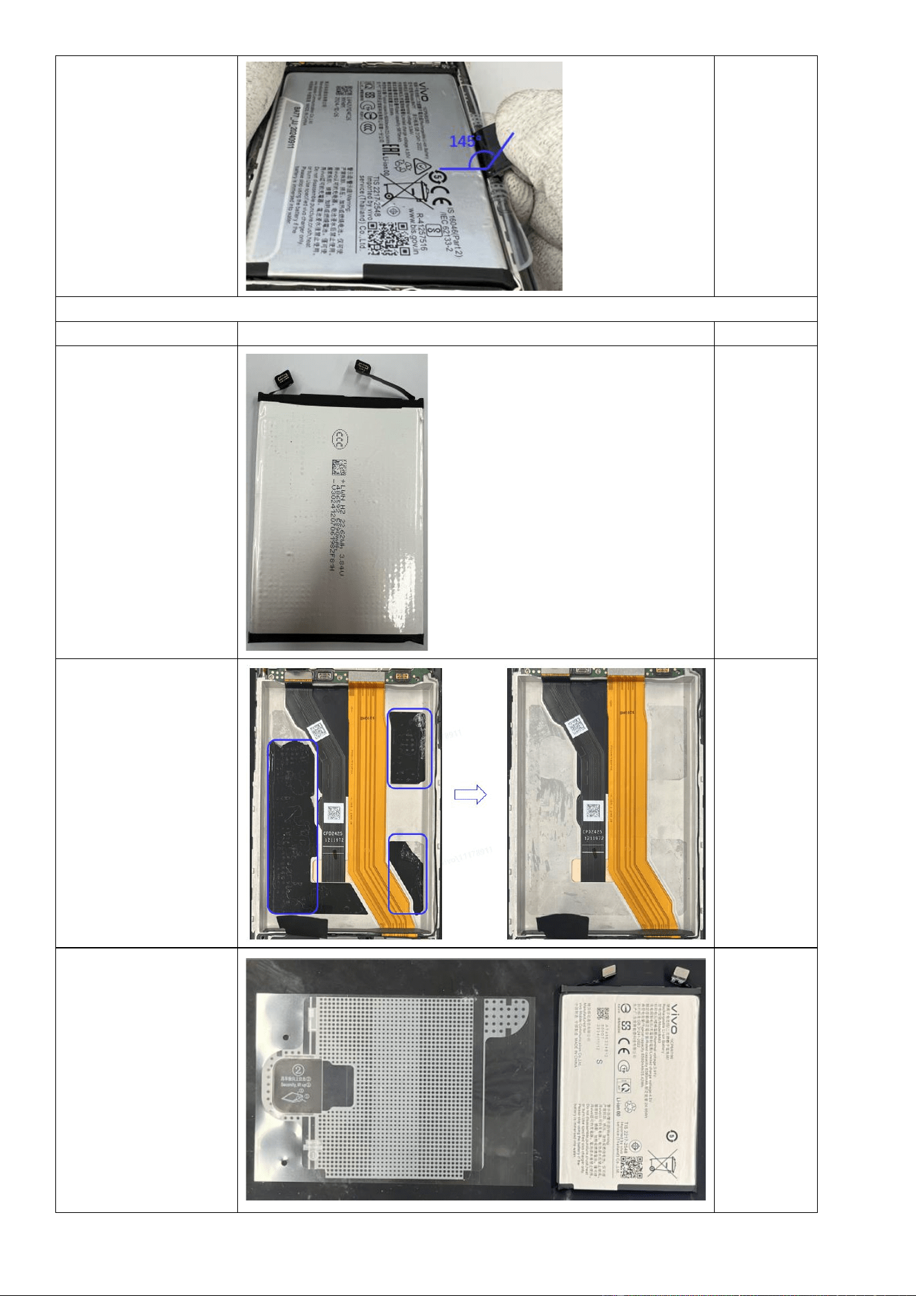
Step 4: Slowly pull the
battery PET film by its
pull tab, maintaining a
145° angle between
the tab and battery
surface during pulling.
注意手部不
要挡住电池
区域
Assembly
Operation
Illustration
Remarks
Step 1: Inspect the
battery for swelling,
deformation, or
damage. If any
defects exist, the
battery cannot be
reused and must be
replaced.
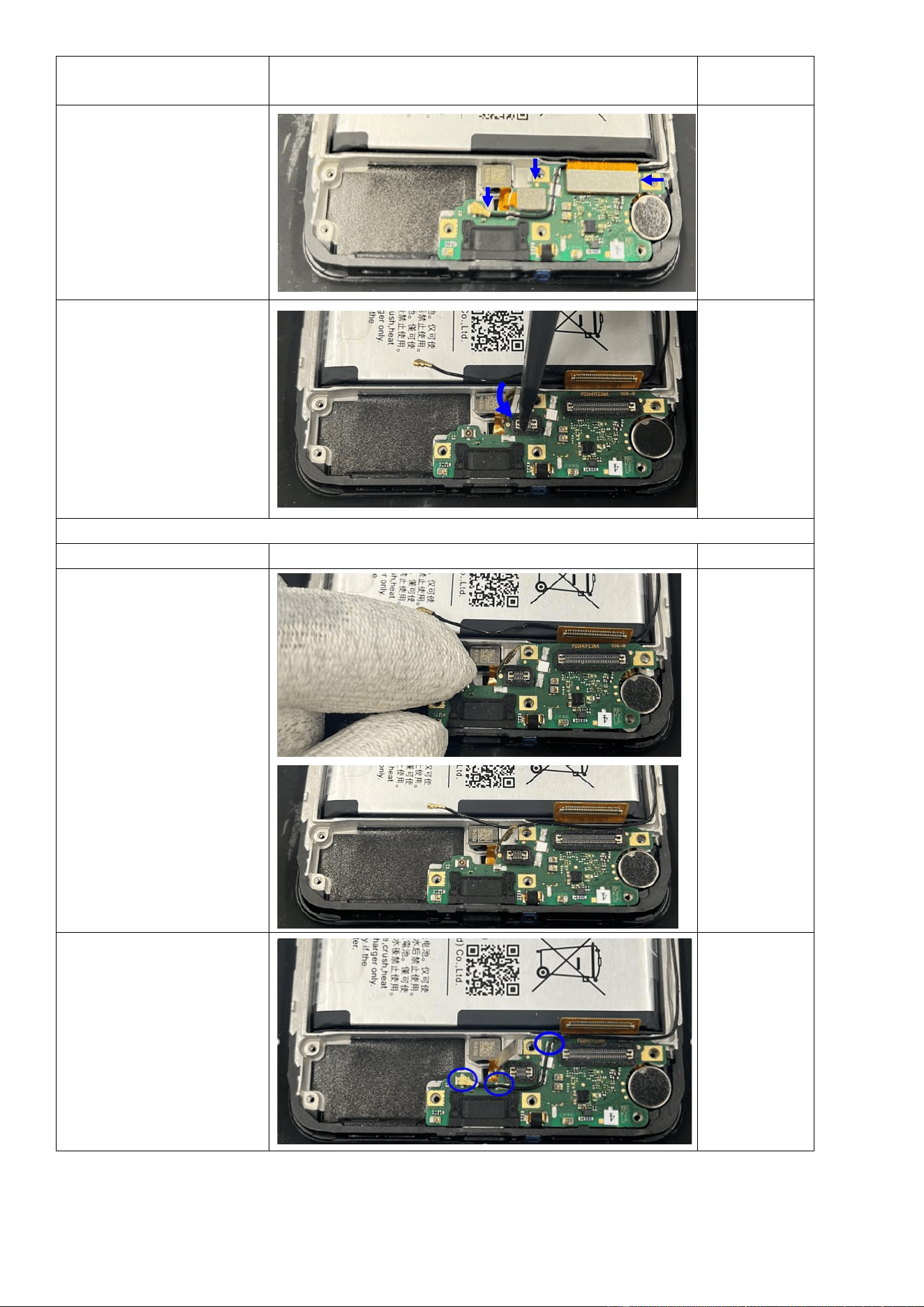
Step 2: Remove the
battery PET disc from
the mainboard upper
cover and clean any
residual adhesive,
especially any black
adhesive in the
indicated areas.
Step 3: Take a new
battery PET disc and
attach it to the battery
as illustrated.
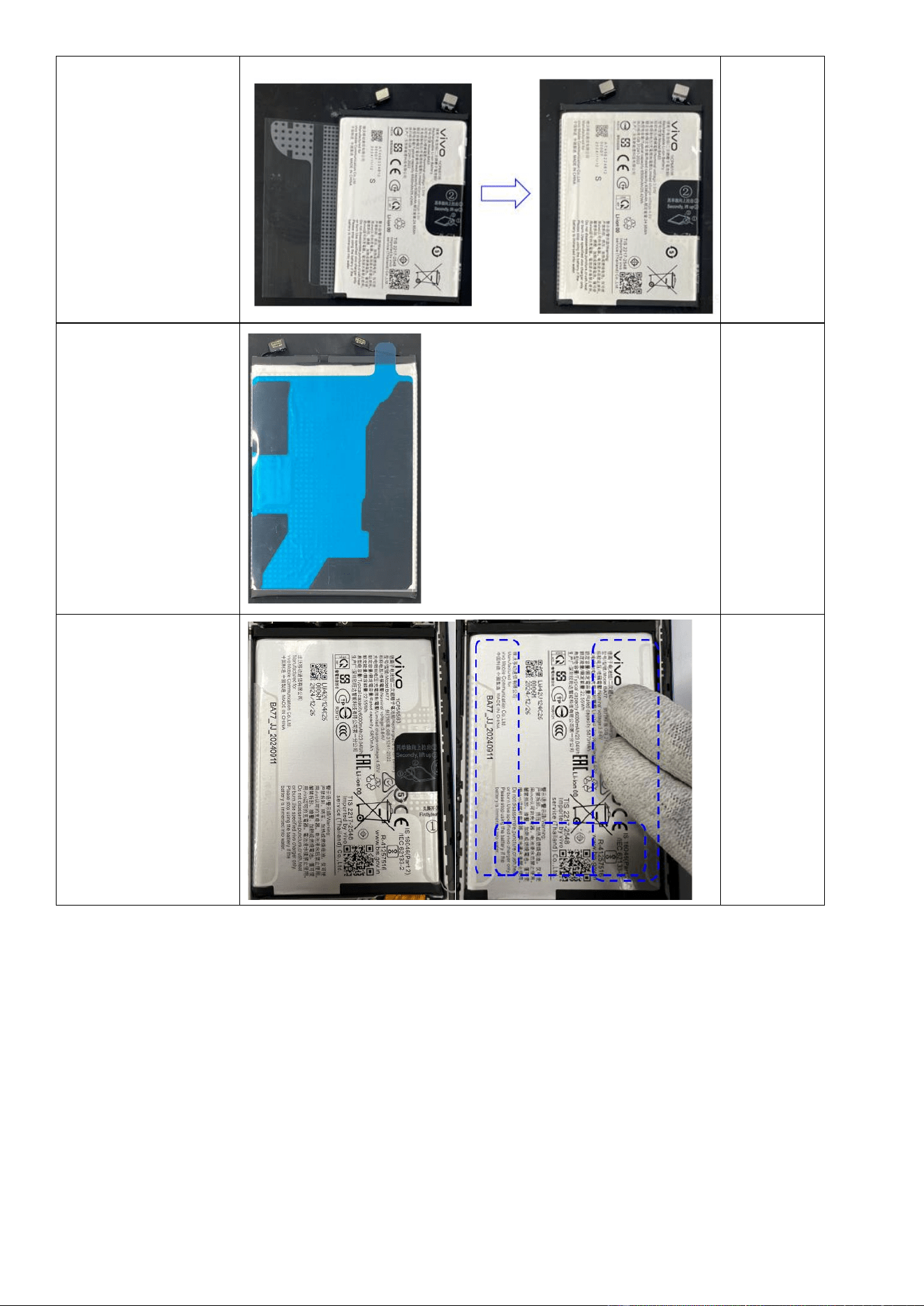
Step 4: Adhere the
battery backing tape to
the battery as shown in
the picture and then
peel off the blue release
film.
Step 5: Before
installation, make sure
that the battery and
battery compartment
are free of foreign
objects. Install the
battery into the
compartment and press
the indicated adhesive
areas with your fingers
to activate bonding.
4.3.9 Replace the display assembly
Difficulty: medium
Duration: 15–20 minutes
Required spare parts: display assembly
Disassembly
Operation
Illustration
Remarks
Step 1: Remove the back cover.
See Section 4.3.1.
Step 2: Remove the middle
frame.
See Section 4.3.2.
Step 3: Remove the M board
bracket.
See Section 4.3.3.
Step 4: Remove the M board.
See Section 4.3.6.
Step 5: Remove the upper
speaker.
See Section 4.3.7.
Step 6: Remove the lower
speaker.
See Section 4.3.4.
Step 7: Remove the ANA board.
See Section 4.3.5.
Step 8: Remove the battery.
See Section 4.3.8.
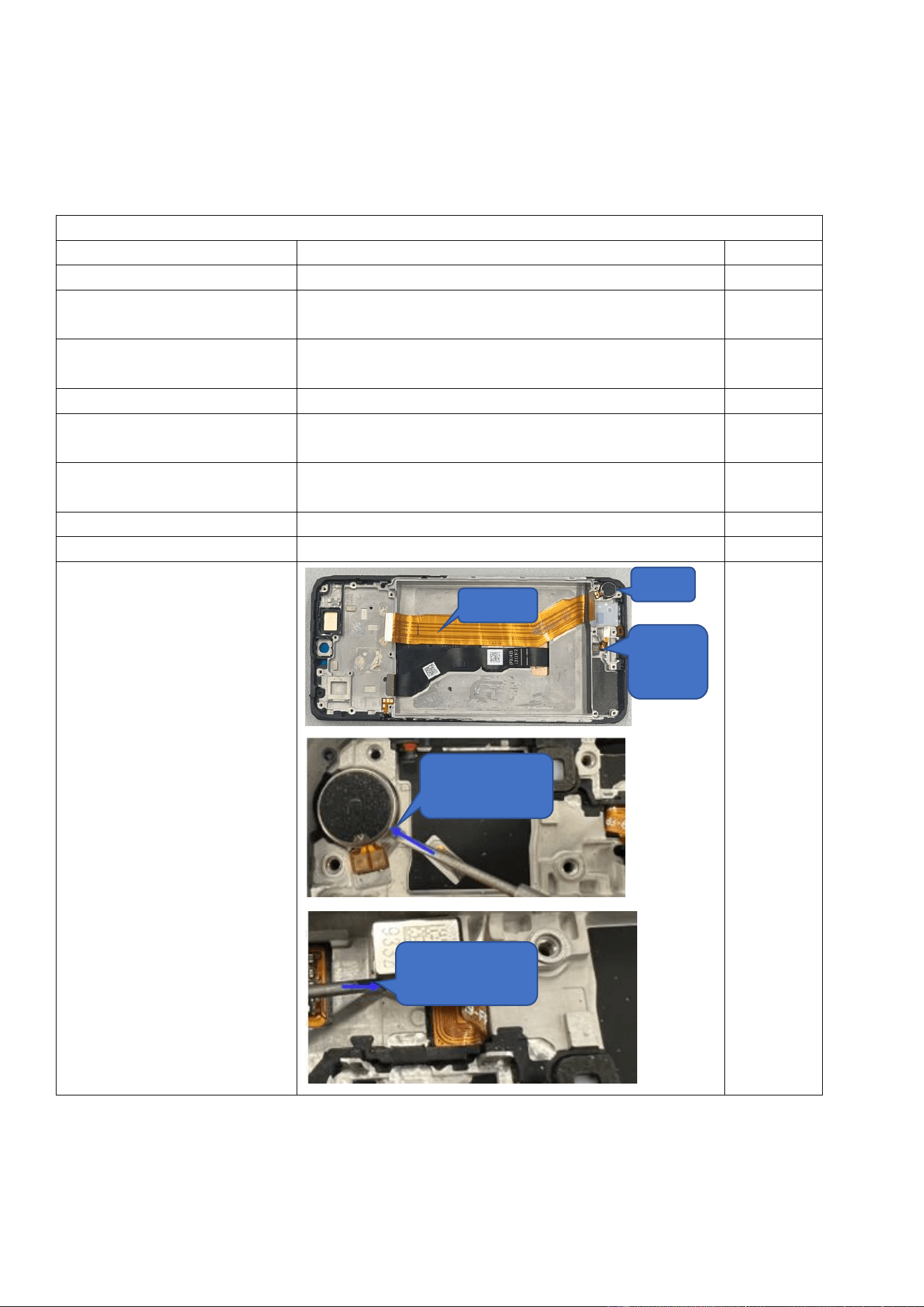
Step 9: Remove the FMA board,
fingerprint scanner, and motor.
FMA Board
Motor
Fingerprint
Scanner
Remove the motor from
here.
Remove the fingerprint
scanner from here.
Step 10: The removal is done.
Assembly
Operation
Illustration
Remarks
Step 1: Install the upper speaker,
M board, cameras, motor,
fingerprint scanner, and ANA
board.
See the following sections: 4.3.5, 4.3.6, and 4.3.7.
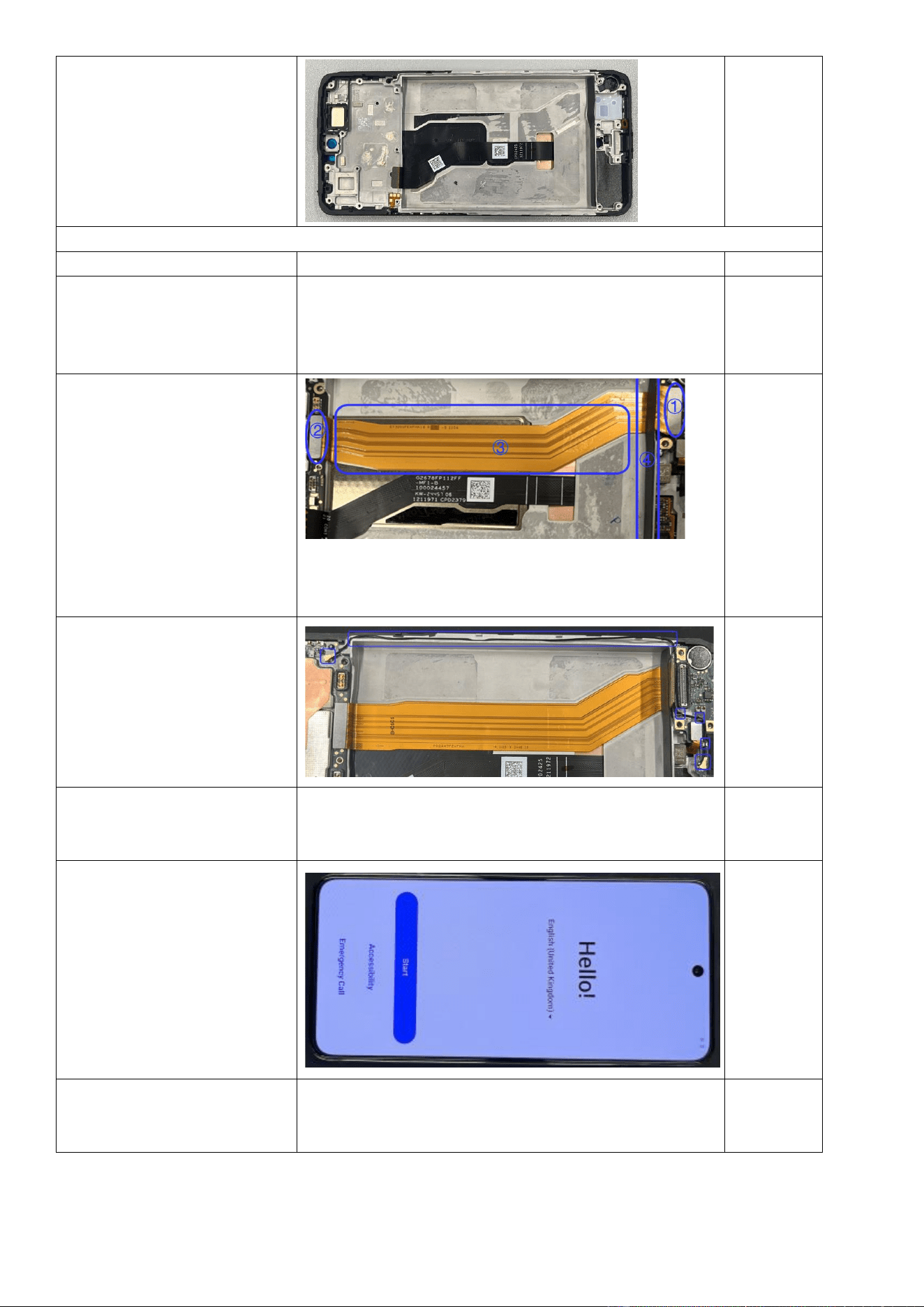
Step 2: Install the FMA board:
First, peel off the FMA release
liner. Then, connect one of the
FMA BTB connectors to the M
board and the other to the ANA
board. Finally, secure the FMA
board to the battery
compartment and adhere it to
the soft pad at the bottom of the
battery compartment.
Step 3: Install the coaxial cable:
First, connect one end of the
coaxial cable to the M board.
Then, route the cable through
the cable slot. Finally, connect
the other end of the coaxial
cable to the ANA board.
Step 4: Install the lower speaker,
battery, M board bracket, and
back cover.
See the following sections: 4.3.1, 4.3.3, 4.3.4, and 4.3.8.
Step 5: Power on the device to
verify normal screen display.
Step 6: Perform calibrations.
After assembly, calibrate the rear cameras, in-display
fingerprint scanner, infrared proximity sensor, and ambient
light sensor as specified in Section 3.2.3.
4.3.10 Replace the side buttons
Difficulty: low
Duration: 6–8 minutes
Required spare parts: side button assembly
Disassembly
Operation
Illustration
Remarks
Step 1: Remove the back
cover.
See Section 4.3.1.
Step 2: Remove the
middle frame.
See Section 4.3.2.
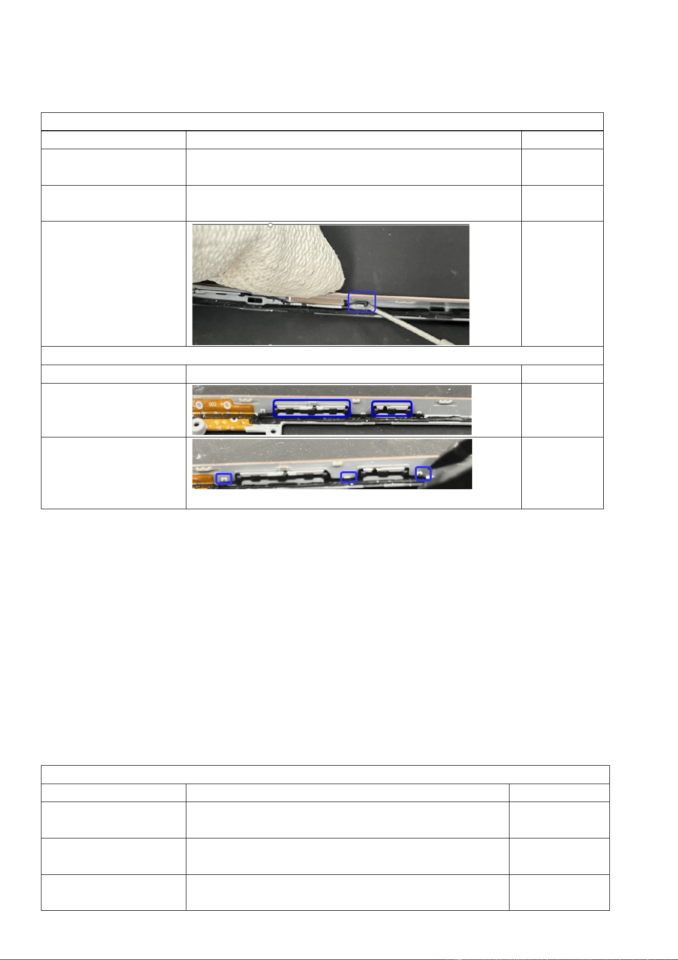
Step 3: Use a flat-head
screwdriver to press the
button, and then pry out
the side button snap-fits
from the indicated slots.
Assembly
Operation
Illustration
Remarks
Step 1: Place the new side
buttons into their slots.
Step 2: Use pointed anti-
static tweezers to put the
button silicone plugs into
the snap-fits.
4.3.11 Replace the display module
Difficulty: high
Duration: 20–50 minutes
Required spare parts: display module
Before you remove the display module:
1. Wear gloves to prevent finger cuts from the metal pry pick.
2. Insert the pry pick only between the cover and screen. Inserting the pry pick to the middle frame gaps can cause
scratches.
3. Prepare some glue (purchase code: 5121839), which is required for some models.
Disassembly
Operation
Illustration
Remarks
Step 1: Remove the back
cover.
See Section 4.3.1.
Step 2: Remove the
middle frame.
See Section 4.3.2.
Step 3: Remove the M
board bracket.
See Section 4.3.3.
Step 4: Remove the M
board.
See Section 4.3.6.
Step 5: Remove the
battery.
See Section 4.3.8.
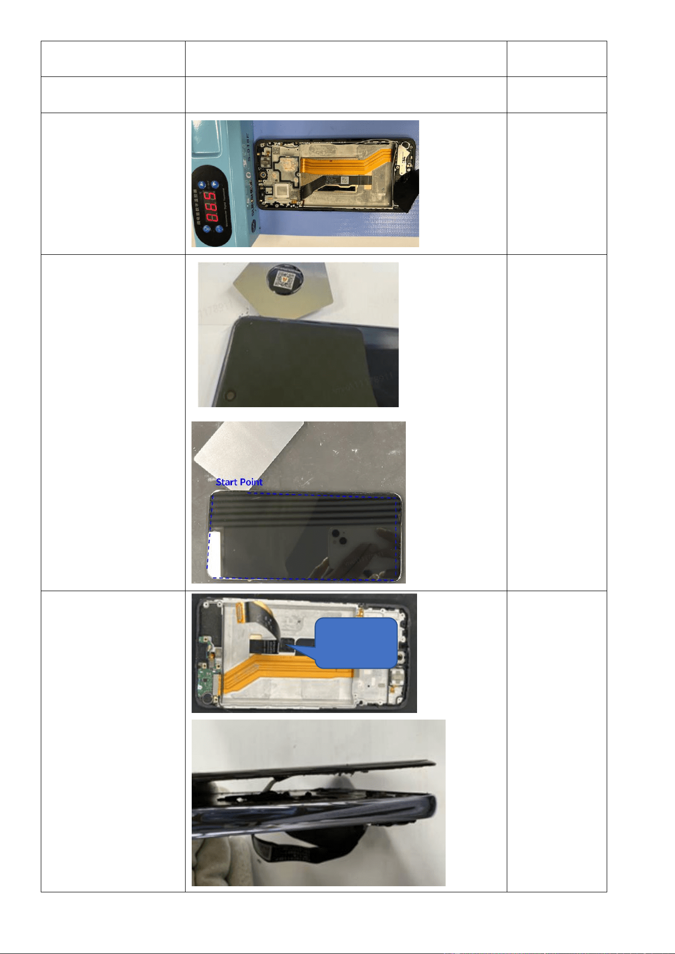
Step 6: Heat the display
at 65°C for 5 minutes on
the heating pad.
Step 7: Insert a metal pry
pick 3 mm deep from the
device's top-right corner
to create a gap between
the display and the main
upper part, and then
switch to a PET pry sheet
for full disassembly.
Complete
disassembly
immediately
after heating.
Delays may cause
cooling and
difficulty. Use a
metal pry pick
only for stubborn
areas.
Step 8: After separating
all edges, remove the
display FPC, and then
gently remove the display
by lifting it upward.
Pull up the
display FPC.
Assembly
Operation
Illustration
Remarks
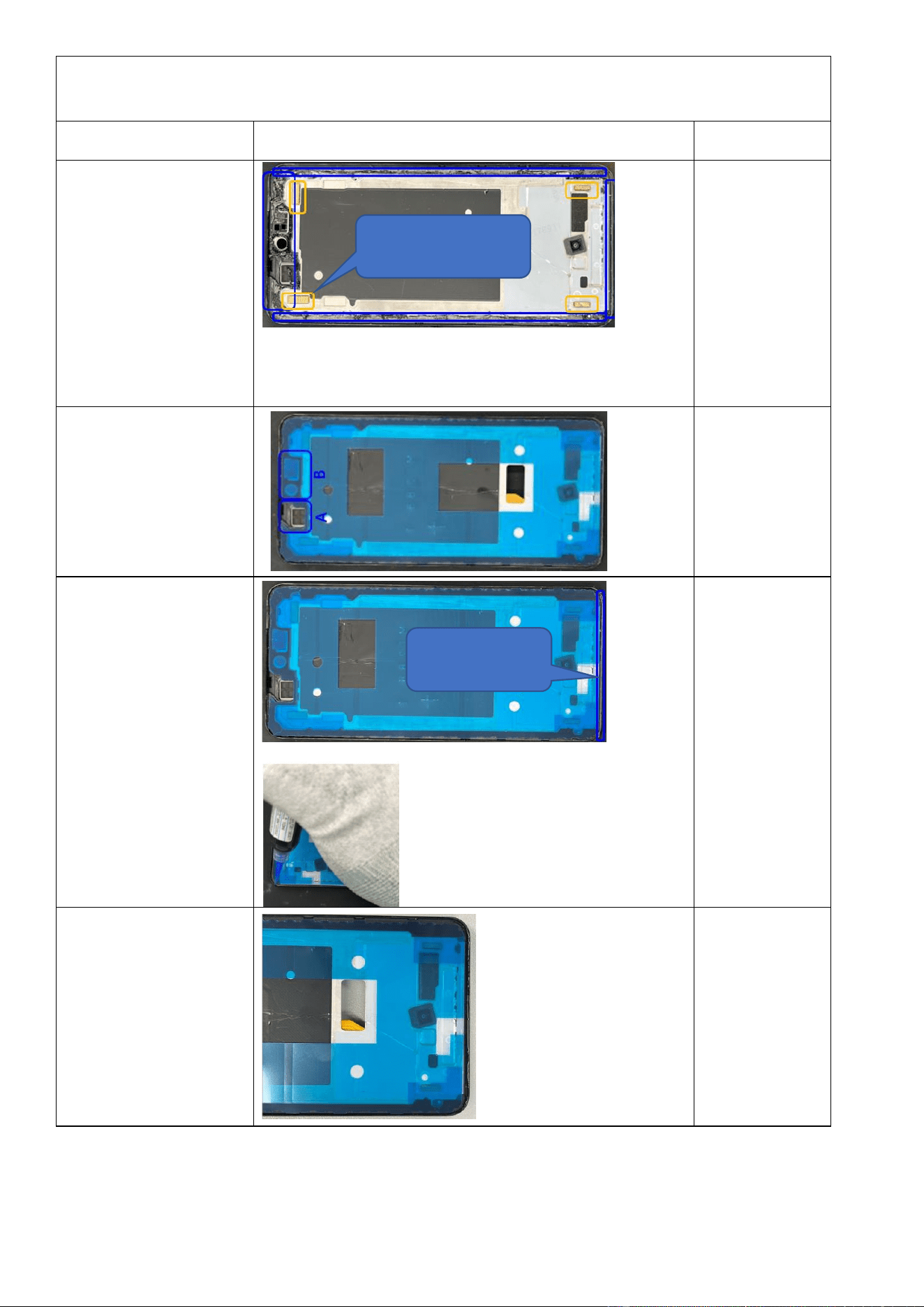
Step 1: Use pointed
tweezers to clean residual
adhesive from the back of
the main upper part and
the bottom edge. Inspect
the anti-static foam and
replace it if it is damaged.
Step 2: Apply the display
adhesive tape to the main
upper part. Match
positions A and B with
corresponding locations.
Press the adhesive tape
to activate bonding.
Step 3: Take a bottle of
glue, clear any cured glue
from the applicator tip to
ensure proper glue flow,
and apply glue on the
bottom edge of the
device. Clean excess glue
inside with a pry tool.
Adjust uneven glue with
the applicator tip.
Pose Guide
Step 4: After glue
application, remove all
adhesive release liners.
The figure on the right
side shows how it looks
after proper glue
application.
Apply glue on the
bottom edge.
Replace damaged anti-static
foam.
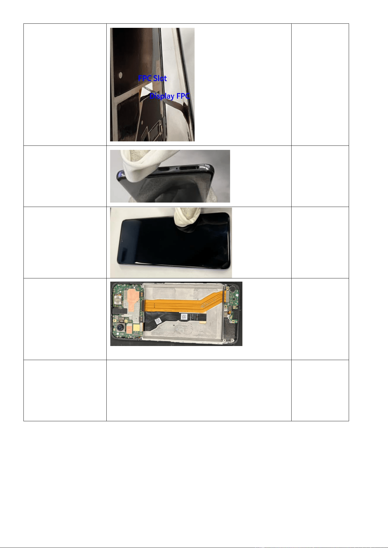
Step 5: Insert the display
FPC into the FPC slot in
the middle frame, as
shown in the figure. Put
the display in position,
align it with the main
upper part, and fully
engage them.
Step 6: Wipe excess glue
from the bottom edge
with a lint-free cloth.
Step 7: After assembly,
wrap your fingers with a
lint-free cloth and firmly
press along all adhesive
areas for 1 minute to
activate bonding.
Step 8: Install the M
board, remove the
release liner of the
display FPC adhesive
tape, connect the display
FPC BTB connector, and
secure the FPC from the
bottom up.
Step 9: Install the lower
speaker, M board, upper
speaker, ANA board,
battery, M board bracket,
middle frame, and back
cover.
See Sections 4.3.1 through 4.3.8.
Make sure that
the display can
light up before
you install the
back cover.
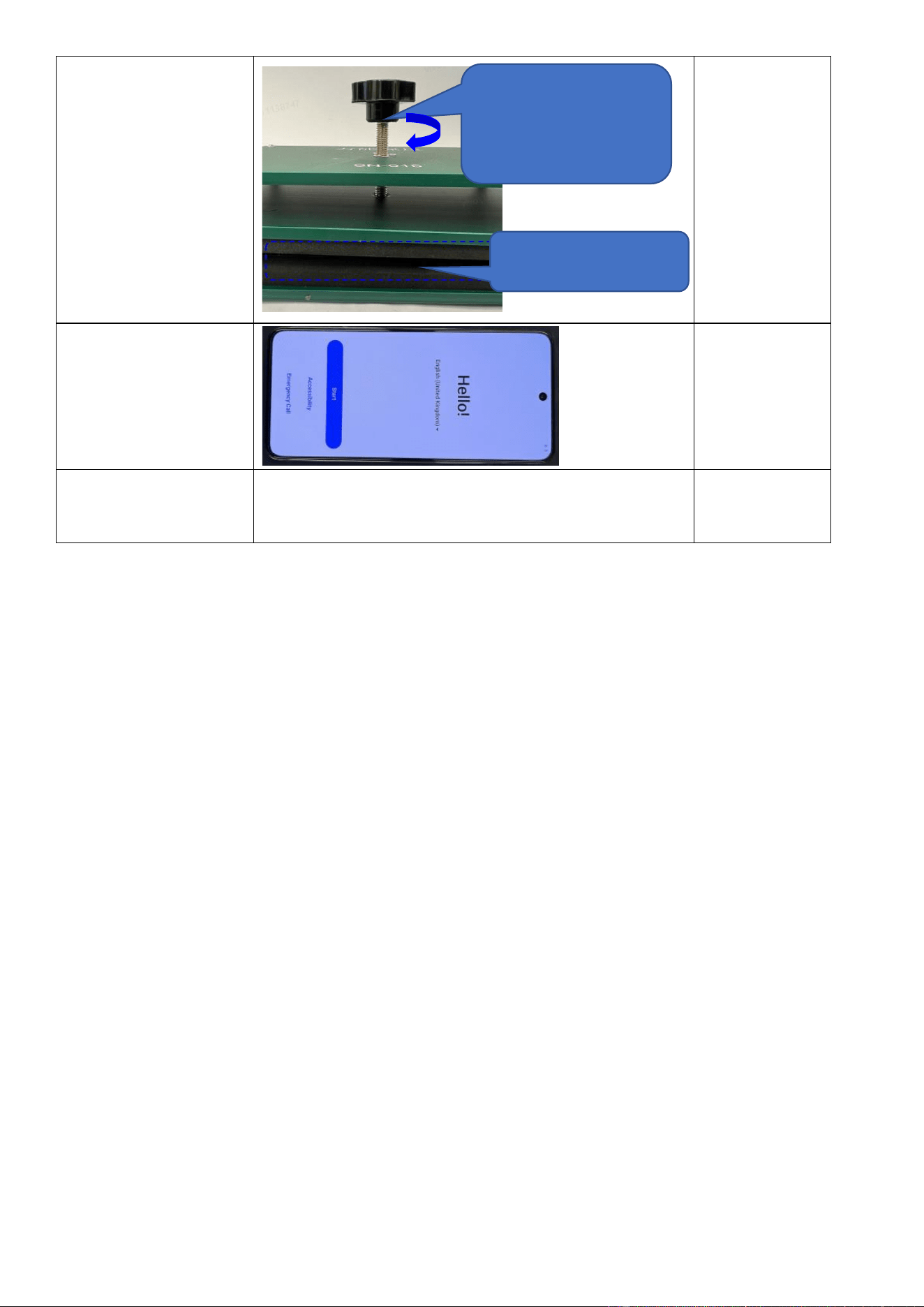
Step 10: After full
assembly, put the device
into the pressure fixture
as shown and maintain
pressure for 30 minutes.
Step 11: Power on the
device to verify its
functionality.
Step 12: Perform
calibrations.
After assembly, calibrate the rear cameras, in-display
fingerprint scanner, infrared proximity sensor, and ambient
light sensor as specified in Section 3.2.3.
② Turn the knob clockwise until you
cannot continue with a proper force,
and wait 30 minutes.
① Put the device into the pressure
fixture.