USER MANUAL
Before using, please read the operating instructions carefully to
ensure proper application and achieve satisfactory results.
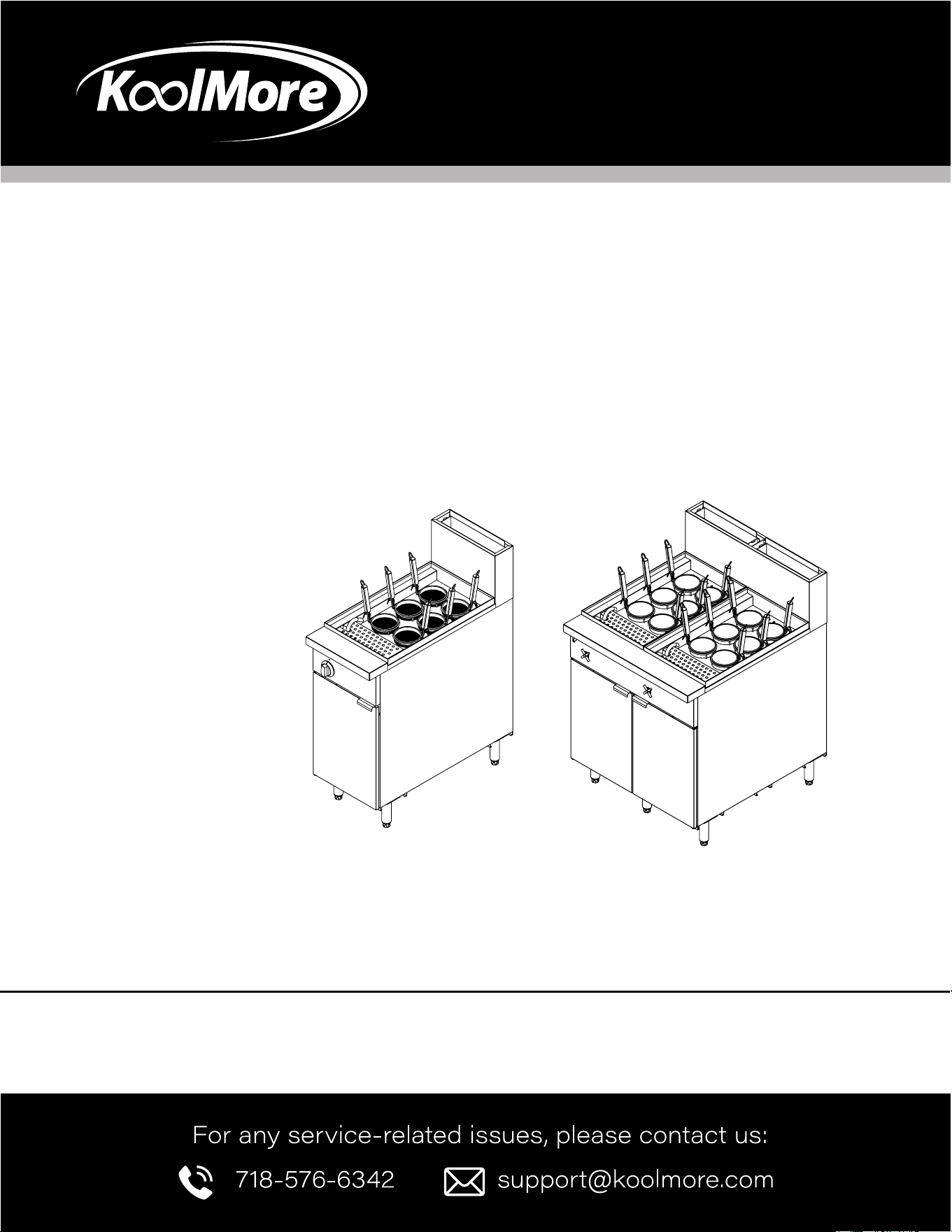
KoolMore Commercial Pasta Cooker
Models: KM-PC6-NG | KM-PC12-NG
PASTA COOKER
46-7/8
1189
45-7/8
1167
11-3/4
300
15-5/8
398
12-3/4
323
4-1/2
115
NPT 1/2
Gas Inlet
NPT 1/2
Water Inlet
NPT 1
Water Outlet
36-1/2
926
35-3/8
900
4-1/2
115
6-1/4
160
32-3/4
831
5/8
17
5-7/8
150
20-1/8
510
26-5/8
676
10
254
5-1/2
140
26-5/8
676
12-1/8
307
9-7/8
252
2
50
4-1/2
114
1-1/8
30
46
1167
46-7/8
1190
13-1/8
333
13-1/8
333
4-1/2
115
31-3/8
798
12-7/8
327
3
75
12-7/8
327
NPT 1/2
Gas Inlet
NPT 1
Water Outlet
NPT 1/2
Water Inlet
NPT 1/2
Gas Inlet
NPT 1
Water Outlet
NPT 1/2
Water Inlet
35-3/8
900
4-1/2
115
32-3/4
831
1-5/8
41
6-3/4
170
20-1/8
510
26-5/8
676
10
254
5-1/2
140
26-5/8
676
9-7/8
251
36-1/2
926
2-7/8
74

Stay informed with the latest information
for your KoolMore Appliance.
If you need any assistance or have questions, our customer
support team is here to help.

3
Contents
Safety .......................................................................... 4
Installation ................................................................... 5
Operation .................................................................... 8
Maintenance ............................................................ 10
Troubleshooting ......................................................... 12
Warranty ..................................................................... 13

4
SAFETY
Before attempting to operate your unit, read the instructions in this manual thoroughly.
WARNING boxes contain information about actions or conditions that may cause or result in a mal-
function of your system.
The gas noodle cooker is designed for boiling pasta, noodles, vegetable etc. This cooker uses a milli-
volt temperature control circuit, which requires no external power.
This model adopts an open-tank design with no tubes, which makes cleaning the water tank quick
and easy.
The noodle cooker requires installation of legs or optional casters at point of use. All noodle cookers
are shipped with a package of standard accessories. Each noodle cooker is adjusted, tested, and
inspected at the factory before crating for shipment.
Water tanks are constructed of welded, heavy-gauge stainless steel. Heat is supplied by two stainless
steel burners, which are installed under the tank bottom.
A drain is installed at the right hand of the water tank, with a front-controlled manual ball valve.
Each noodle cooker is equipped with a thermostat for precise temperature control. The thermostat is
located at the front part of the water tank for rapid response to changes in loads and to provide the
most accurate temperature measurement.
A high temperature thermostat (hi-limit) shuts off gas to the burner assembly if the controlling ther-
mostat fails.
If unit arrives damaged:
This unit was carefully inspected and packed before leaving the factory. The transportation company
assumes full responsibility for safe delivery upon acceptance of the equipment for transport.
What to do if your equipment arrives damaged:
1. File a claim for damages immediately, regardless of the extent of damages
2. Inspect for and record all visible loss or damage, and ensure that this information is noted on the
freight bill or express receipt and is signed by the person making the delivery.

5
INSTALLATION
PROPER INSTALLATION
Proper installation in accordance with the instructions that follow is essential for ecient, trouble-free
operation of your noodle cooker. Any unauthorized alterations made to this equipment will void the
warranty.
Upon arrival, inspect the cooker carefully for visible or concealed damage.
Clearance and Ventilation:
The cooker(s) must be installed with a 6” clearance at both sides and back when adjacent to combus-
tible construction; no clearance is required when adjacent to noncombustible construction. A mini-
mum of 24” clearance should be provided at the front of the cooker.
One of the most important considerations for ecient cooker operation is ventilation. Make sure
the cooker is installed to eciently remove combustion by-products and that the kitchen ventilation
system does not produce drafts that interfere with proper burner operation. The cooker ue opening
must not be placed close to the intake of the exhaust fan, and the cooker must never have its ue
extended in a “chimney” fashion. An extended ue will change the combustion characteristics of the
cooker, causing longer recovery time and frequently causing delayed ignition. To provide the airow
necessary for good combustion and burner operation, the areas surrounding the noodle cooker front,
sides, and rear must be kept clear and unobstructed.
The cooker must be installed in an area with an adequate air supply and adequate ventilation. Ade-
quate distances must be maintained from the ue outlet of the cooker to the lower edge of the venti-
lation lter bank.
National Code Requirements:
The type of gas for which the cooker is equipped is marked on the data plate attached to the inside of
the cooker door. Connect a cooker marked “NAT” only to natural gas, and those marked “PRO” only to
propane gas.
When installing this equipment in the United States, the installation must conform to the latest edition
of the National Fuel Gas Code, ANSI Z223.1. In Canada, installation must conform to the latest edition
of Standard CAN-/ GCA-B149.1 or .2, “Installation Codes for Gas Burning Appliances & Equipment.” In
addition to the applicable national code or standard, installation must also be in accordance with any
local codes for the area in which the equipment is installed.
Installation shall be made with a gas connector that complies with national and local codes. In the
United States, the applicable code is ANSI Z21.69 with Addenda, “Standard for Connectors for Mov-
able Gas Appliances.” Quick-disconnect devices, if used, shall likewise comply with national and local
6
codes. In the United States, the code is ANSI Z21.41, “Standard for Quick-Disconnect Devices for Use
with Gas Fuel.”
Pre-connection Preparations:
After the cooker has been positioned under the cook station exhaust hood, ensure the following has
been accomplished:
• Adequate means must be provided to limit the movement of cookers without depending upon
the gas line connections. If a exible gas hose is used, a restraining cable must be connected at
all times when the cooker is in use. The restraining cable and installation instructions are packed
with the exible hose in the accessories box that was shipped with your unit.
• These cookers must be stabilized by installing restraining chains on noodle cookers equipped with
casters or anchor straps on cookers equipped with legs. Follow the instructions shipped with the
casters/legs to properly install the chains or straps.
• Level cookers equipped with legs by extending the adjustable portion of the leg out approximately
1 inch, and then further adjust the legs, ensuring the cooker is level and at the proper height under
the exhaust hood. For cookers equipped with casters, the oor where the cooker is to be installed
must be level.
• Refer to the data plate on the inside of the cooker door to verify that the cooker is congured for
the proper type of gas before connecting the noodle cooker quick-disconnect device or piping
from the gas supply line.
• Verify that the minimum and maximum gas supply pressures for the type of gas to be used are in
accordance with the table above.
Connect to the Gas Line:
The size of the gas line used for installation is very important. If the line is too small, the gas pressure
at the burner manifold will be low. This may cause pilot outage, slow recovery, and delayed ignition.
The incoming gas supply line should be a minimum of 1½” in diameter. All single cookers using natu-
ral gas require a ¾” or 1/2” connection. For cookers using LP gas, one pipe size smaller may be used.
If in doubt about the correct pipe size, consult the local gas company.
1. Before connecting new pipe to your unit, the pipe must be thoroughly blown out to remove any for-
eign particles. If these foreign particles get into the burner and controls, they will cause improper
and sometimes dangerous operation.
2. Connect the quick-disconnect hose to the noodle cooker quick-disconnect tting at the rear of the
cooker and to the building gas line.
NOTE: Some noodle cookers are congured for a rigid connection to the gas supply line. These units
are connected directly to the gas supply line. When using thread compound, use very small amounts
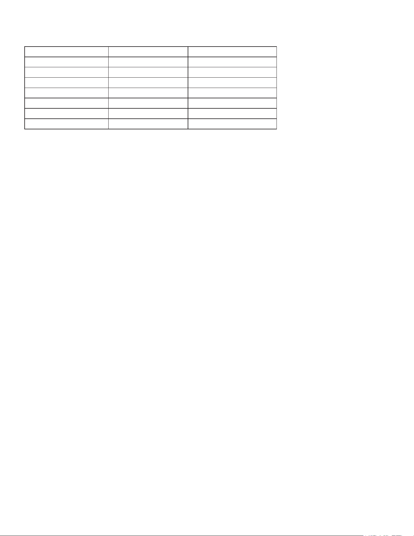
Model KM-PC6-NG KM-PC12-NG
Dimension (in) 15.75 x 33.78 x 47.24 31.5 x 33.78 x 47.24
L.P.G Orice (No./in) 50# / 0.07in*2 50# / 0.07in*4
NAT Orice (No./in) 35# / 0.11in*2 35# / 0.11in*4
Total Rate (BTU/H) 70,000 70000 *2
LP.IN. W.C 10" W.C 10" W.C
NAT.IN. W.C 4" W.C 4" W.C
Gallon 11 11+11

7
on male threads only. Use a pipe thread compound that is not affected by the chemical action of LP
gases (Loctite™ PST56765 Sealant is one such compound).
3. DO NOT apply compound to the rst two threads. This will ensure that the burner orices and con-
trol valve do not become clogged.
4. Open the gas supply to the cooker and check all piping, ttings, and gas connections for leaks. A
soap and water solution should be used for this purpose.
NOTE: The cooker must be disconnected from the gas supply piping during any pressure testing of
the gas supply piping pressures equal to or greater than ½ psig (3.45 kPa or 13.84 in. W.C.).
5. Close the cooker drain valve and ll the water tank with water or boil-out solution to the bottom
WATER LEVEL line at the rear of the water tank. Light the cooker and perform the boil-out proce-
dures that are described in the “Start-Up Procedure” and “Boiling Out the Water Tank” topics.
6. It is suggested that the burner manifold pressure be checked at this time by the local gas compa-
ny or an authorized service agent. Refer to “Check Burner Manifold Pressure” in this manual for
the proper procedure.
Water and Gas Connection:
This model is specially designed to boil pasta and noodles. Water should be connected to this unit.
The black pipe is for gas connection. The middle pipe is for wastewater drainage. Please make sure
you have the right connection. A wrong connection would damage the valve and cause gas leakage.
8
OPERATION
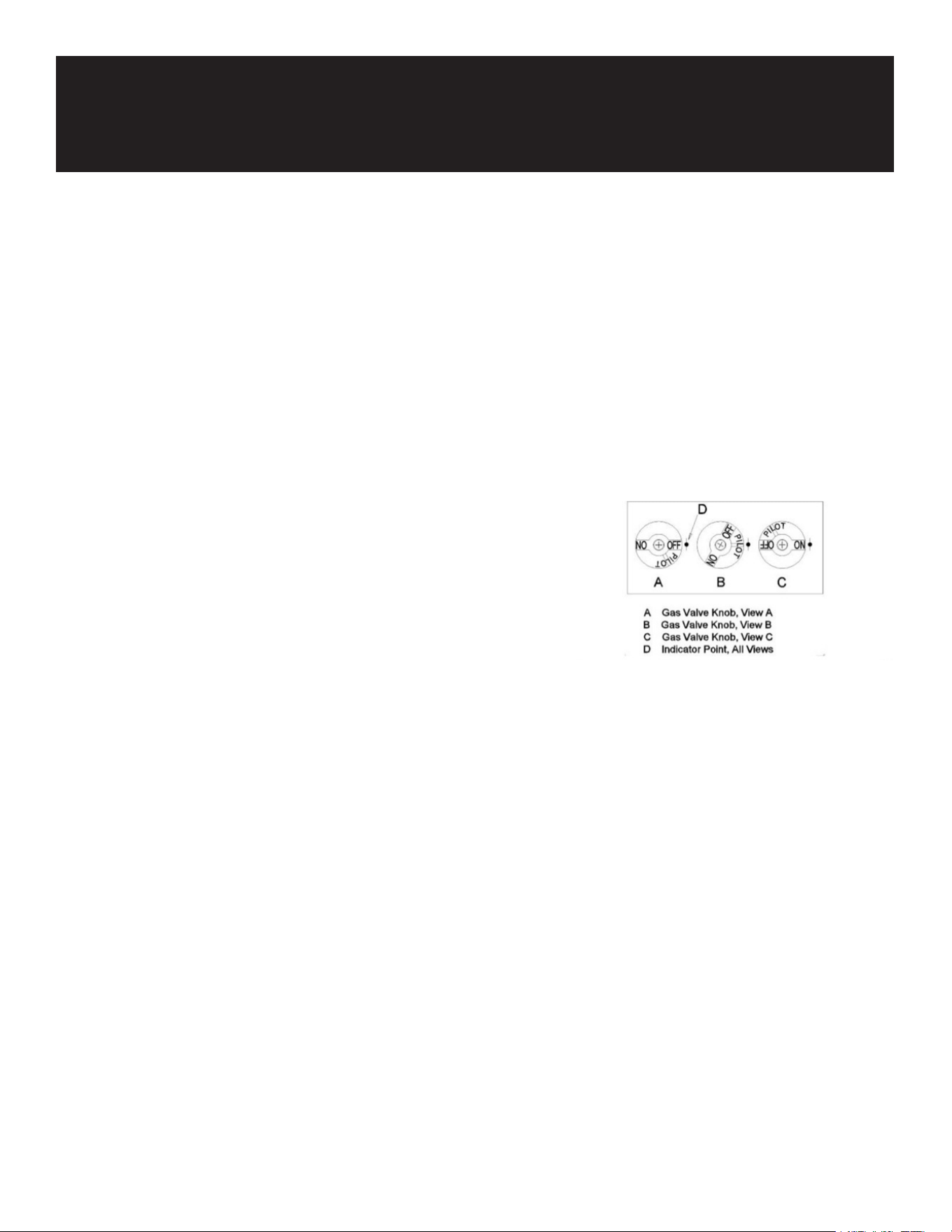
Operating the Gas Valve:
The knob on the gas valve is placed in the PILOT or ON position by rotating it counter-clockwise. To
return the knob to the OFF position, the knob must be depressed slightly to disengage its stop tab,
then rotated clockwise.
Lighting the Pilot and Burner:
1. Open the door.
2. Turn the thermostat OFF (see gure below, view A). The
thermostat is located behind the door.
3. Push the gas control valve knob and turn it to OFF. Wait 5
minutes for unburned gas to vent.
4. Push and turn the gas control valve knob to the “L” in PI-
LOT (see gure below, view B).
5. While still holding the knob in, light the pilot with a lit
ame. Continue to depress the knob until the pilot re-
mains lit when the knob is released. If the pilot does not
remain lit, repeat steps 3 through 5.
6. If the pilot fails to remain lit, wait ve minutes before at-
tempting to re-light.
7. Depress and turn the gas control knob to ON (see gure
below, view C).
8. If the gas supply is interrupted, repeat steps 2 through 6.
Filling With Water:
Turn on the faucet to ll the water tank with water. Do not exceed the max water-level.
Thermostat Operation:
Note: The boiling point of water might vary at different altitudes.
The thermostat is connected to a graduated knob located inside the cooker door. Rotating the knob
clockwise to the desired cooking temperature (set-point) directly adjusts the thermostat to that tem-
perature. The thermostat controls the water tank temperature by regulating the gas supply to the
burner via the gas valve.
The thermostat is in the full OFF position when the word OFF is at the top of the knob. A “click” will be
heard when the knob is rotated from the OFF position to a temperature or when it is rotated back to

9
the OFF position.
Draining:
Rotate the gas valve knob to the PILOT or OFF position.
Open the drain valve slowly.
Clean all food particles and residual water from the water tank before relling.
Close the drain valve and rell the water tank with clean water.

10
MAINTENANCE
Daily Checks and Services:
Inspect Cooker and Accessories for Damage:
1. Look for loose wires, leaks, foreign material in the water tank or inside the cabinet, and any other
indications that the noodle cooker and accessories are not ready and safe for operation.
2. Inspect the burner deectors to verify that each is positioned directly above its orice, and that
the ame ignites approximately 2½ inches (60mm) above the orice. The ame should strike the
center of the deector and be a rich blue color.
Clean Cooker Cabinet Inside and Out:
1. Clean inside the cooker cabinet with a dry, clean cloth. Wipe all accessible metal surfaces and
components to remove accumulations of dust.
2. Clean the outside of the cooker cabinet with a clean, damp cloth soaked with dishwashing deter-
gent, removing dust and lint from the cooker cabinet.
Quarterly Checks and Services:
Drain and Clean Water Tank:
During normal usage of your cooker, a deposit of water scale will gradually form on the inside of the
tank. This deposit must be periodically removed to maintain your cooker’s eciency. Follow the pro-
cedures for draining the water tank, then follow the “Boiling Out the Water Tank” procedures.
Clean Detachable Parts and Accessories:
Wipe all detachable parts and accessories with a clean cloth dampened with a detergent solution.
Rinse and thoroughly dry each part.
Semi-annual Checks and Services:
Check Burner Manifold Pressure:
1. Ensure that the gas valve knob is in the OFF position.
2. Remove the pressure tap plug from the burner manifold.
3. Insert the tting for a manometer or pressure gauge into the pressure tap hole.
4. Place the gas valve in the PILOT position and light the pilot. When the pilot lights and continues to
burn, increase the setting on the thermostat knob until the burner lights. Compare the manometer
or gauge reading to the appropriate table below.
5. If the burner manifold pressure does not meet the specications in the tables in Step 4, unscrew
the slotted cap from the top of the gas valve regulator (adjacent to the gas valve vent tube) and
turn the adjusting screw to obtain the correct pressure. Turn the screw clockwise to increase pres-

11
sure, counter-clockwise to decrease pressure.
6. After adjusting the manifold pressure to the correct value, reinstall the regulator cap and turn the
gas valve knob to the OFF position.
7. Remove the manometer or pressure gauge tting from the pressure tap hole and reinstall the pipe
plug.
8. Place the gas valve in the PILOT position and check for gas leaks. If no leaks are found, re-light the
pilot and return the unit to operation.
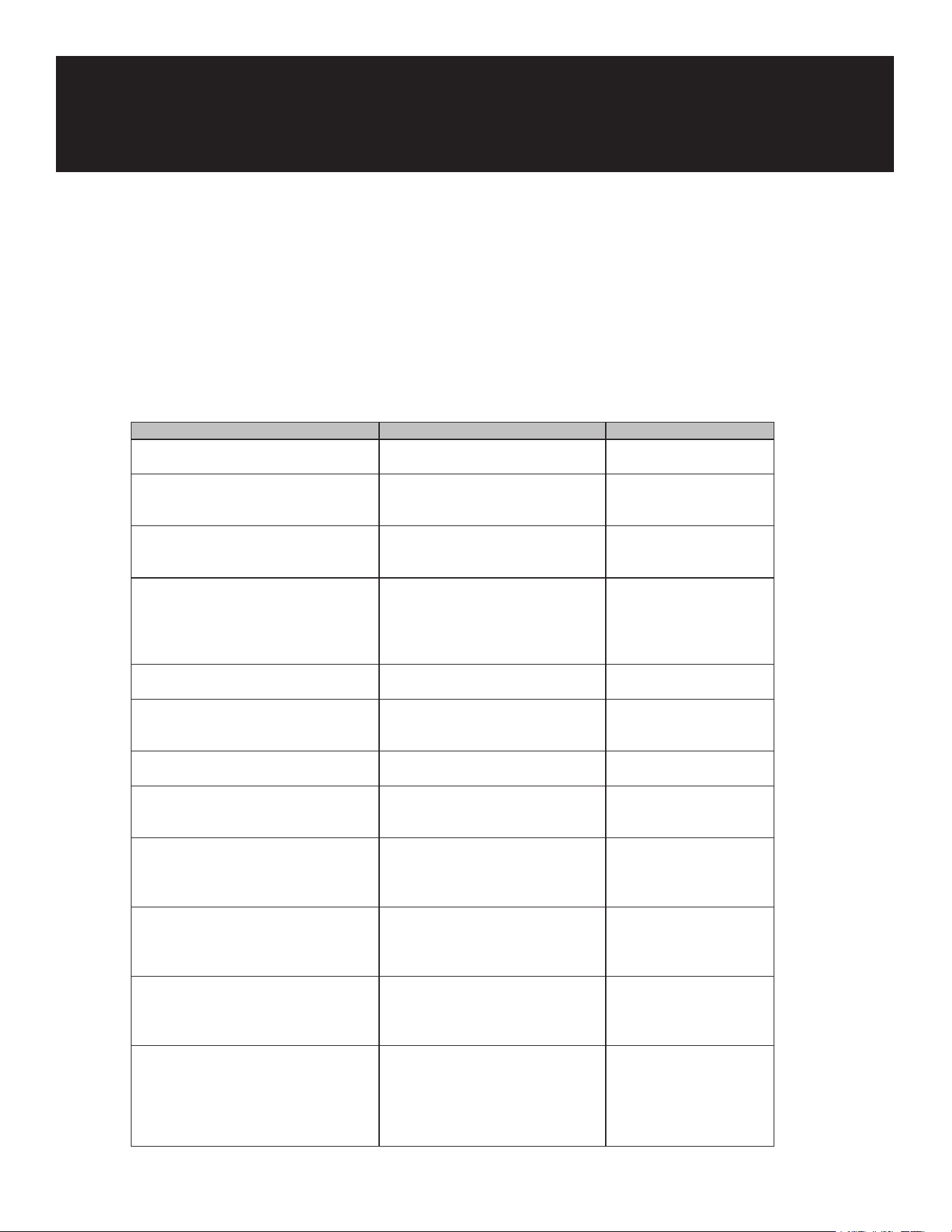
12
Problem Probable Cause Corrective Action
Burner does not light at all - Pilot is not lit - Light the pilot.
- Loose, dirty, or corroded terminals on
the gas valve
- Clean and tighten terminals
on the gas valve.
- Loose, dirty, or corroded terminals on
the thermostat
- Clean and tighten terminals
on the thermostat.
Burner does not light all the way around - One or more burner orices are clogged- Turn the gas valve knob to
the OFF position. Use a thin
wire to clear obstruction from
burner orices.
- Blocked ue - Clear blockage from the ue.
Burner experiences delayed ignition - Too little make-up air in the kitchen - Adjust the kitchen ventilation
system to increase make-up
air.
Flame rolling out from under noodle cooker - Flue obstructed - Remove obstruction from
the ue.
Pilot repeatedly goes out - Clogged pilot orice - Use a small wire to clear
obstruction from the pilot
orice.
- Pilot ame blowing away from the pilot
generator (excessive draft in the kitchen)
- Eliminate the draft in the
kitchen.
- Pilot generator not inserted fully into
the pilot burner
- Reinsert the pilot generator
into the pilot burner until the
ame surrounds the tip.
- Corroded connection where the pilot
generator connects to the gas valve
- Clean the pilot generator
connection at the gas valve.
- If all of the above causes have been
ruled out, the probable causes are low
pilot ame, pilot generator low millivolt
output, high resistance in hi-limit
thermostat contacts, or a defective pilot
magnet in the gas valve
- Call for service.
TROUBLESHOOTING
Operator Troubleshooting:
The tables that follow provide operators with a list of possible malfunctions, the probable causes of the malfunctions, and
the corrective actions to take to correct the problem. In some cases, the operator may not be able to correct the problem,
but will at least be able to accurately diagnose the problem, assisting a qualied service technician in restoring the equip-
ment to full operation in the shortest possible time.
Warning: This task should be performed by qualied service personnel only.
Warning: The noodle/pasta cooker must be lled with water during this procedure.

13
WARRANTY
LIMITED WARRANTY
Koolmore Supply, Inc. extends a limited warranty to the original purchaser, guaranteeing that this Koolmore
product is free from manufacturing defects in material or workmanship for one year from the date of
purchase.
Should you discover any such defect within the warranty period, Koolmore Supply, Inc., reserves the right to
repair or replace the product without charge, or to cover the cost of replacement parts and repair labor needed
to correct defects present at the time of purchase or resulting from regular usage, when the appliance has been
installed, operated, and maintained as per the instructions provided.
At its sole discretion, Koolmore Supply Inc. may decide to replace the product. In such an event, your replace-
ment appliance will carry the warranty for the remaining term of the original unit's warranty period.
This warranty is valid exclusively to the original purchaser of the product and only applicable within the United
States. The warranty commences from the date of original consumer purchase. Proof of the original purchase
date will be required to obtain service under this warranty.
Under this limited warranty, your sole and exclusive remedy will be product repair, as outlined above. All
services must be provided by a Koolmore-designated service company.
To claim warranty or request repair service:
Email support@koolmore.com. Please include your name, address, phone number, warranty repair request,
and a copy of your proof of purchase receipt. Alternatively, visit koolmore.com and use the contact us page. A
Koolmore customer service representative will promptly arrange service for your appliance.
We thank you for choosing Koolmore.
WARRANTY EXCLUSIONS
This limited warranty will not cover:
1. Failure of the product to perform during power failures or interruptions,
or due to inadequate electrical service.
2. Damage incurred during transportation or handling.
3. Damage caused by accidents, vermin, lightning, winds, re, oods, or acts of God.
4. Damage resulting from accidents, alterations, misuse, abuse, improper installation, repair, or maintenance.
This includes using any external device that alters or converts the voltage or frequency of
electricity.
5. Unauthorized product modications, repairs by unauthorized centers, or use of non-approved
replacement parts.
6. Abnormal cleaning and maintenance not aligned with the user's manual.
7. Use of incompatible accessories or components.
8. Any costs associated with repairs or replacements under these excluded circumstances shall be the
responsibility of the consumer.