
6/12/24V BATTERY STARTER/CHARGER
MODEL NO: SUPERSTART550E, SUPERSTART750E,
SUPERSTART950E
Thank you for purchasing a Sealey product. Manufactured to a high standard, this product will, if used according to these instructions,
and properly maintained, give you years of trouble free performance.
IMPORTANT: PLEASE READ THESE INSTRUCTIONS CAREFULLY. NOTE THE SAFE OPERATIONAL REQUIREMENTS, WARNINGS & CAUTIONS. USE
THE PRODUCT CORRECTLY AND WITH CARE FOR THE PURPOSE FOR WHICH IT IS INTENDED. FAILURE TO DO SO MAY CAUSE DAMAGE AND/OR
PERSONAL INJURY AND WILL INVALIDATE THE WARRANTY. KEEP THESE INSTRUCTIONS SAFE FOR FUTURE USE.
1. SAFETY
IMPORTANT: To reduce the risk of a battery explosion, follow these instructions and those published by the battery manufacturer and the
manufacturer of any equipment you intend to use in the vicinity of the battery. Remember to review warning marks on all products and on
engines. Modern vehicles contain extensive electronic systems. Check with the vehicle manufacturer for any specic instructions regarding the
use of this type of equipment on each vehicle. No liability will be accepted for damage/injury where this product is not used in accordance with all
instructions.
1.1. SAFETY INSTRUCTIONS
9 Read instructions carefully before using this product.
9 The product is only to be used to start 12V and 24V vehicles. It may lead to damage or be dangerous if used for other dierent
voltage rated machines.
9 This product is not intended to be used as a replacement vehicle battery.
9 Ensure the vehicle’s battery terminals are clean and battery clamps are connected properly before jump starting the vehicle. Dirty or
corroded on battery terminals may eect the starting performance.
8 DO NOT crank the engine for more than 3 seconds at a time. The jump start feature is designed for short term operation only.
Operating the jump start feature for more than 3 seconds may cause damage to the unit. Allow the jump starter to cool down for
at least 2 minutes after each cranking.
9 Remove the battery clamps from the vehicle battery immediately after the engine has started.
9 Wear safety eye protection and protective clothing. Avoid touching eyes while working with a battery.
9 Wash immediately with soap and water if battery acid contacts skin or clothing. If acid enters eye, ush eye immediately with cool,
clean running water for at least 15 minutes and seek immediate medical attention.
9 If the internal battery is leaking do not use and have battery replaced immediately. Isolate the spillage and clean appropriately.
WARNING!: Battery acid can cause skin damage/burns, respiratory issues, eye damage and throat irritation so please ensure all
precautions have taken place.
9 Remove personal metallic items such as rings, bracelets, necklaces and watches.
9 Keep the unit in good working order and condition. Replace damaged parts immediately.
9 Use only recommended parts. To use unapproved parts may be dangerous and will invalidate your warranty.
9 The unit must only be opened and checked by qualied service personnel. DO NOT disassemble the unit for any reason.
8 DO NOT modify the product.
9 Keep children and unauthorised persons away from the work area.
9 Keep work area clean and tidy and free from unrelated materials. Ensure that there is adequate lighting.
9 If the unit receives a sharp knock or blow, it must be checked by a qualied service agent before being used.
9 Children from age 8 years and above, persons with reduced physical, sensory, or mental capabilities those with lack of experience
and knowledge can use the appliance, if they have been given supervision or instruction concerning use of the appliance in a safe
way to understand the hazards involved.
8 Children shall NOT play with the appliance
9 Cleaning and user maintenance on the appliance shall not be made by children without supervision.
9 The appliance shall be disconnected from its power source during service and when replacing parts and, if that the removal of the
plug is foreseen, it shall be clearly indicated that the removal of the plug has to be such that an operator can check from any of the
points to which he has access that the plug remains removed.
8 DO NOT smoke or allow a spark, or ame in the vicinity of the battery or engine.
8 DO NOT drop any metal item onto the battery as it may spark or short circuit the battery, which could cause an explosion.
8 DO NOT use unit to recharge dry cell batteries that are commonly used with home appliances.
8 DO NOT charge or boost a frozen battery.
8 DO NOT use attachments other than those recommended.
8 DO NOT pull or carry the unit by its cable
8 DO NOT pull the Superstart by negative or positive clamps.
8 DO NOT operate in vicinity of ammable liquids, dusts or gases.
8 DO NOT recharge the unit with a charger/cables that are damaged. Replace immediately. Only use the correct, supplied charger to
recharge the unit.
8 DO NOT use this product to perform a task for which it is not designed.
8 DO NOT store the unit in damp or wet locations or where the temperature may exceed 50°C.
SUPERMIG 550E,750E,950E Issue 1 08/07/24
Original Language Version
© Jack Sealey Limited
Refer to
instructions
Electrical
shock
hazard
Wear eye
protection
Wear
protective
gloves
Warning
corrosive
substance
Keep away
from sources
of ignition
Use in well
ventilated
areas
Keep in dry
area protect
from rain
Warning

8 DO NOT submerge the unit in water.
8 DO NOT use whilst under the inuence of drugs, alcohol or intoxicating medication.
8 DO NOT leave the unit in a totally discharged state for an extended period of time as this may result in permanent damage.
8 DO NOT cross-connect the power leads from the jump starter to the battery. Ensure that positive is to positive and negative is to
negative.
9 Ensure that the unit is fully charged before storage. Keep the unit fully charged on a regular basis.
1.2. ELECTRICAL SAFETY
WARNING! It is the user’s responsibility to check the following:
9 Check all electrical equipment/appliances to ensure they are safe before using. Inspect power supply leads, plugs and all electrical
connections for wear and damage. Sealey recommend that an RCD (Residual Current Device) is used with all electrical products.
Electrical safety information. It is important that the following information is read and understood:
9 Ensure that the insulation on all cables and on the appliance is safe before connecting it to the power supply.
9 Regularly inspect power supply cables and plugs for wear or damage and check all connections to ensure that they are secure.
Important: Ensure that the voltage rating on the appliance suits the power supply to be used and that the plug is tted with the
correct fuse.
8 DO NOT pull or carry the appliance by the power cable.
8 DO NOT pull the plug from the socket by the cable.
8 DO NOT use worn or damaged cables, plugs or connectors. Ensure that any faulty item is repaired or is replaced immediately by a
qualied electrician.
9 If the cable or plug is damaged during use, switch o the electricity supply and remove from use.
9 Ensure that repairs are carried out by a qualied electrician.
9 Ensure that the insulation on all cables and the product itself is safe before connecting to the mains power supply.
9 Ensure that cables are always protected against short circuit and overload.
1.3. PERSONAL SAFETY
8 DO NOT place the charger in the engine compartment or near moving parts or near the battery; place as far away from them as DC
cable permits. Never place a charger directly above a battery being charged; gases or uids from battery will corrode and damage
charger.
8 DO NOT cover the charger while charging.
8 DO NOT expose to rain or wet conditions.
9 Connect and disconnect mains supply after connecting the positive and negative leads to the battery.
8 DO NOT use accessories that are not recommended or sold by the manufacturer as this may cause a risk of re or electric shock/
injury to its operator.
8 DO NOT overcharge batteries by selecting the wrong charge mode.
9 Operate with caution if the charger has received direct hit of force or been dropped. Have it checked and repaired if damaged. Any
repair must be carried out by the manufacturer or an authorised repair agent in order to avoid danger.
1.3.1. GROUNDING AND AC POWER CORD CONNECTIONS
1.3.2. This battery charger is for use on a 230 volt supply. The plug must be plugged into an outlet that is properly installed and grounded
in accordance with electrical regulations. DO NOT use with an ungrounded system. The use of an adapter plug would be deemed to
be unsafe.
2. INTRODUCTION
Suitable for charging 6V, 12V and 24V electrical systems and jump starting 12/24V Vehicles. Fully electronic, microprocessor-
controlled charger with up to ten analysis and charge phases, including trickle/maintenance. Suitable for charging VRLA, GEL,
AGM/EFB, Leisure and Lithium batteries (12V only). Featuring reverse polarity, short circuit, overcharge, overheat and overcurrent
protection systems. BSU mode provides support for the battery during prolonged electronic diagnostic checks. Also features an
alternator check and dedicated repair function.
3. SPECIFICATION
Original Language Version
© Jack Sealey Limited
S
UPERMIG 550E,750E,950E Issue 1 08/07/24
Model No: SUPERSTART550E SUPERSTART750E SUPERSTART950E
Battery Range: 6V - 15-550Ah
12V - 15 - 600Ah
24V - 15-550Ah
6V - 15-550Ah
12V - 15-750Ah
24V - 15-550Ah
6V - 15 -550Ah
12V - 15- 750Ah
24V - 15- 550Ah
Battery Support/DC Supply Mode: 30A 45A 45A
Cable & Clamp Length: 1.8m 1.8m 1.8m
Charging Rates: 6V - 5/10/30A
12V - 10/30/50A
24V - 10/30/50A
6V - 5/10/45A
12V - 10/45/70A
24V - 10A/45A/70A
6V - 5/10/45A
12V - 10/40/80A
24V - 10A/40A/80A
Max Size Battery (Ah) full charge in 12hrs: 12V 600Ah 12V 750Ah 12V - 750AH
Nett Weight: 45kg 45kg 45kg
Plug Type: Bare Wire No plug or cable Bare Wire
Power Supply Cable Length: 1.8m 1.8m 1.8m
Start Peak: N/A 750A 950A
Supply: 230V 230V 230V
Zero Voltage Charging: N/A N/A N/A
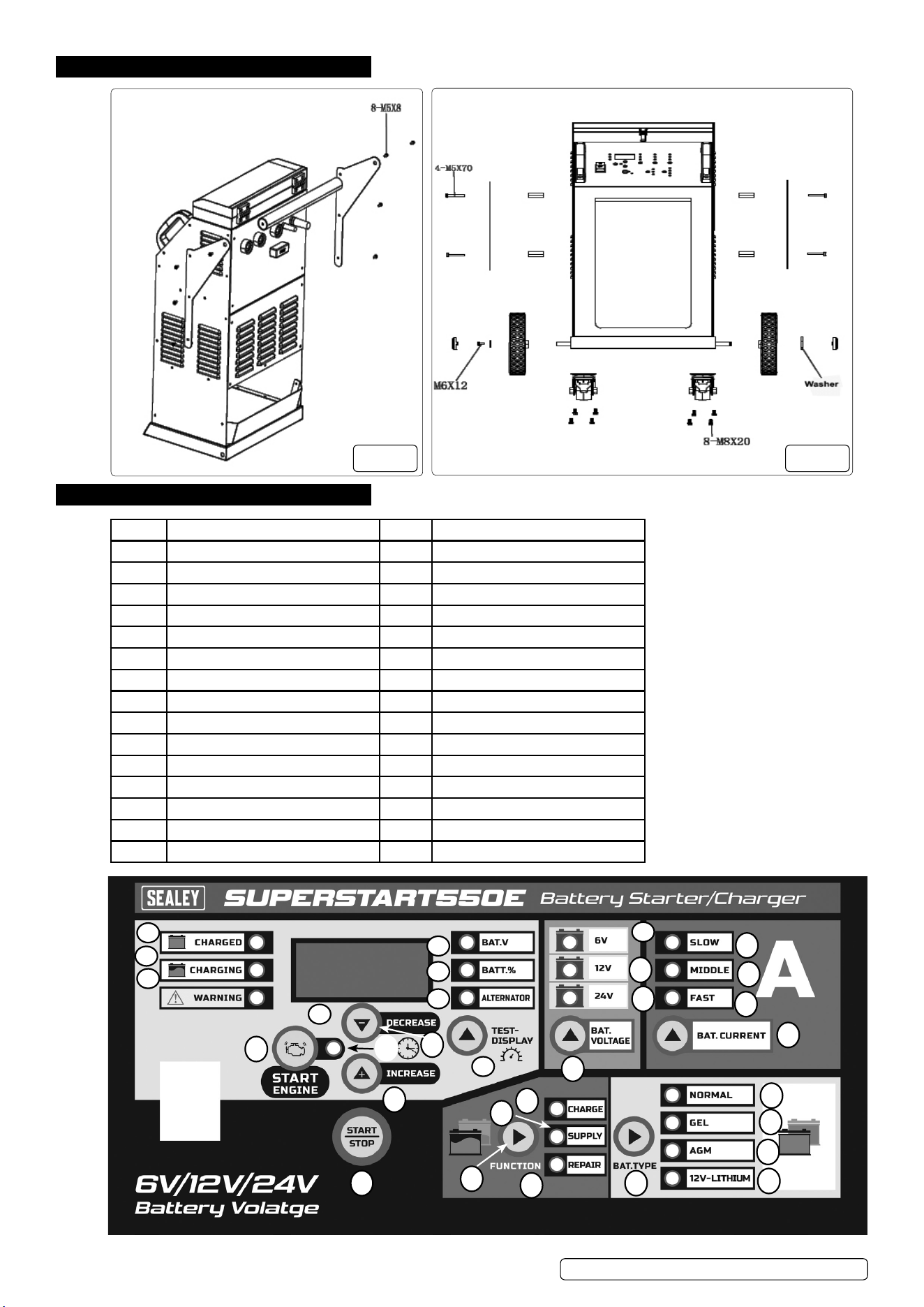
4. ASSEMBLY
5. OPERATION
Item Description Item Description
1 Charged Led Indicator 16 Battery current Button
2 Charging Led Indicator 17 Normal Led Indicator
3 Warning Led Indicator 18 Gel Led Indicator
4 Digital Display 19 Agm Led Indicator
5 Voltage Led Indicator 20 12V-Lithium Indicator
6 Battery % Led Indicator 21 Battery Type Button
7 Alternator % Led Indicator 22 Charge Led Indicator
8 Test Button 23 Supply Led Indicator
9 6V Led Indicator 24 Repair Led Indicator
10 12V Led Indicator 25 Function Button
11 24V Led Indicator 26 Start/Stop Button
12 Battery Voltage Button 27 Increase Button
13 Slow Led Indicator 28 Engine Start Indicator
14 Middle Led Indicator 29 Engine Start Button
15 Fast Led Indicator 30 Decrease Button
© Jack Sealey Limited
Original Language Version
SUPERMIG 550E,750E,950E Issue 1 08/07/24
g.1 g.2
1
2
3
4
5
6
7
8
9
10
11
12
13
14
15
16
17
18
19
20
21
22
23
24
25
26
27
28
29
30
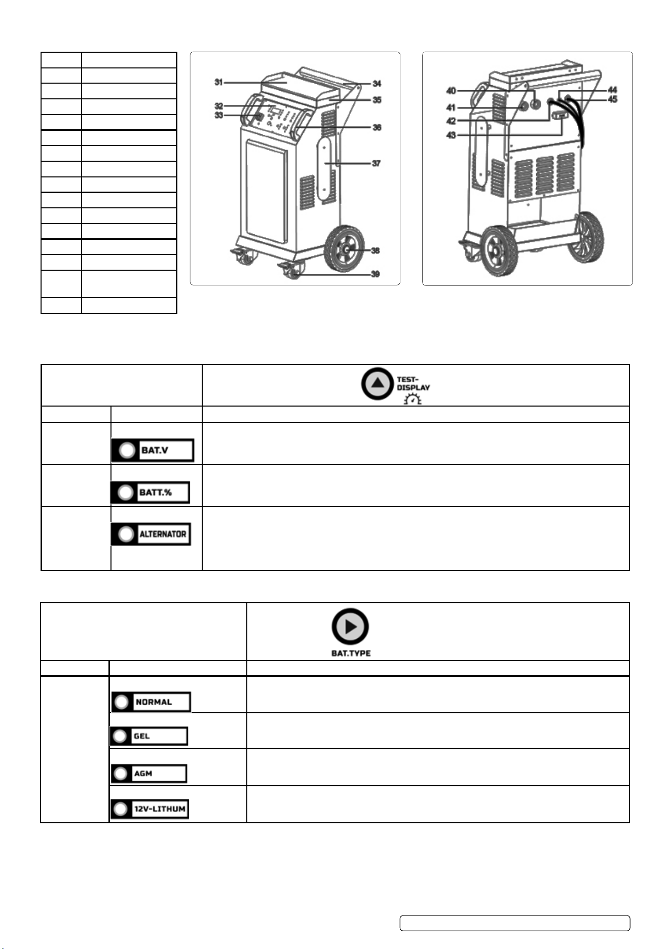
Item Description
31 Setting Table
32 Plastic Panel
33 Switch Button
34 Iron Handle
35 Storage Box
36 Plastic Handle
37 Winding Support
38 Wheel
39 Caster wheel
40 24V quick plug
41 6V/12V quick plug
42 Negative line
43 Fuse
44 Hand-held starter
cable
45 Power cord
5.1. DISPLAY MESSAGES
5.1.1. Start up – After display screen and all LEDs illuminate for 0.5 second, battery voltage shows.
5.2. TEST-DISPLAY BUTTON
5.3. Battery type button
© Jack Sealey Limited
Original Language Version
SUPERMIG 550E,750E,950E Issue 1 08/07/24
TEST-DISPLAY BUTTON
Digital display Indicator LED Description
BAT.V Voltage LED lit When the charger is NOT working in ENGINE START, the display will show the battery VOLTAGE.
BATT.% Battery % LED lit When the charger is NOT working in ENGINE START, the digital display shows percentage of the
battery connected to the charger’s battery clamps.
ALTERNATOR Alternator % LED lit The digital display shows an estimated output percentage of the vehicle’s charging system connected
to the charger’s battery clamps, compared to a properly functioning system. The alternator percent
range is from 0% to 100%. Readings below 0% (13.4 volts/26.8 volts) will read LO and readings above
100% (14.4 volts/28.8 volts) will read HI. If you get a HI or LO reading, have the electrical system
checked by a qualied technician.
BAT. TYPE
Digital display LED indicator Description
NORMAL LED lit STANDARD)-Charged Voltage is 7.2V/14.4V/28.8V.When charging, pressing this button
does NOT work.
GEL LED lit (GEL)-Charged Voltage is 7.5V/14.5V/29V.When charging, pressing this button does NOT
work
AGM LED lit (AGM)-Charged Voltage is 7.8V/14.8V/29.6V.When charging, pressing this button does
NOT work.
LITHIUM LED lit Charging 12V lithium-ion batteries only, including (4-cell LiFePO4).
© Jack Sealey Limited
Original Language Version
SUPERMIG 550E,750E,950E Issue 1 08/07/24
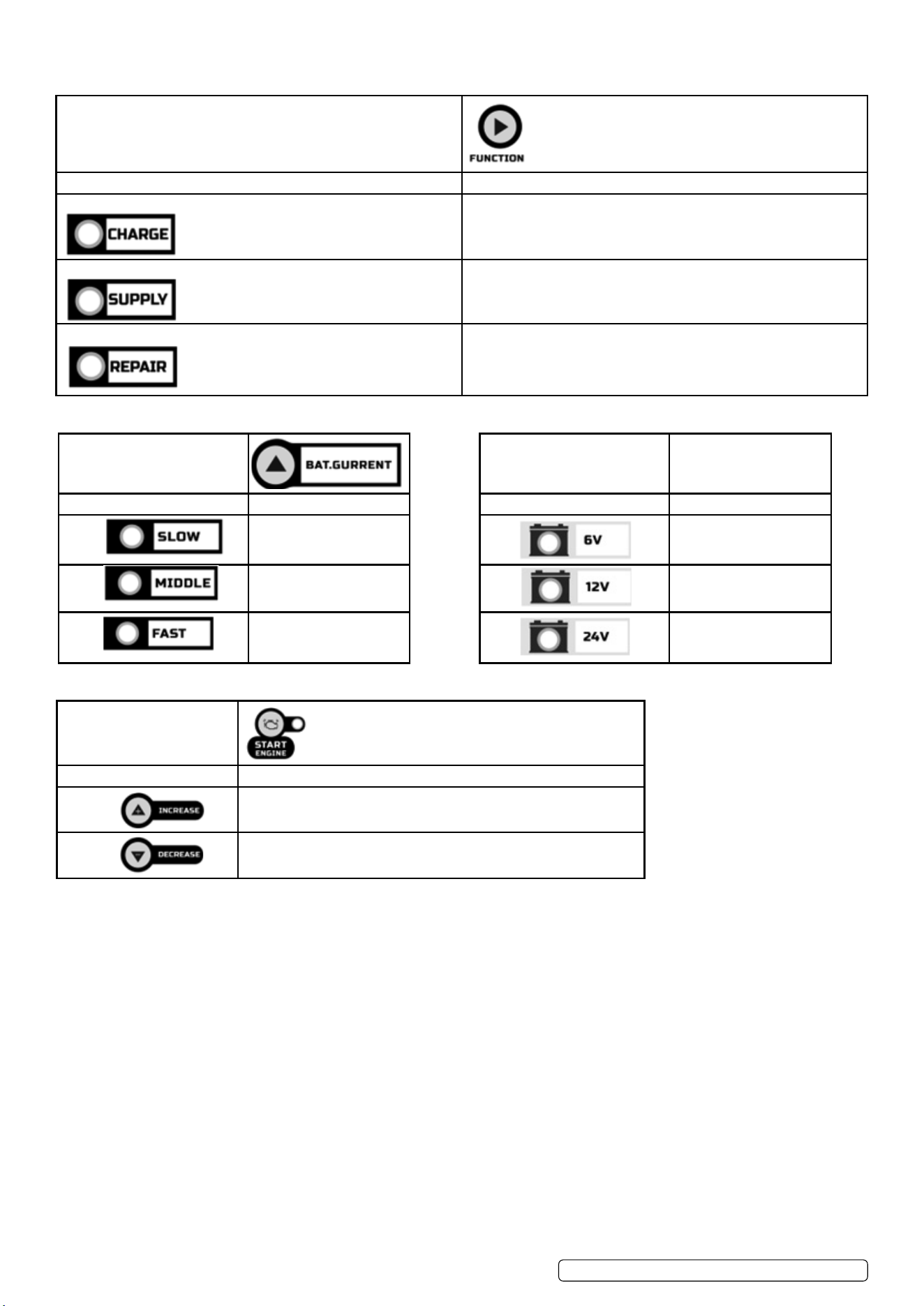
5.4. FUNCTION SELECTION BUTTON
FUNCTION
Mode Explanation
CHARGE The operating mode of the charger is charging mode.
SUPPLY Provide a stable output to help the equipment work normally and
check and repair..
REPAIR Provide a positive pulse voltage to charge the battery that has been
idle for a long time or the dead battery.
5.5. CURRENT SELECTION BUTTON BATTERY VOLTAGE SELECTION BUTTON
5.6. ENGINE START BUTTON
ENGINE START (press ENGINE START BUTTON to enter) – Provides additional amps for cranking an engine with a weak or
run-down battery.
WARNING: Always use in combination with a battery. Must NOT touch or disconnect clamps when ENGINE START mode works,
otherwise there may be serious injuries to people or property.
5.7. CONNECTING TO THE BATTERY
5.7.1. Identify polarity of battery posts. The positive battery terminal is typically marked by these letters or symbol (POS, P, +). The negative
battery terminal is typically marked by these letters or symbol (NEG, N, –).
8 DO NOT make any connections to the carburetor, fuel lines, or thin metal parts.
5.7.2. Identify if you have a negative or positive grounded vehicle. This can be done by identifying which battery post (NEG or POS) is
connected to the chassis.
5.7.3. For a negative grounded vehicle (most common): connect the RED POSITIVE clamp rst to the positive battery terminal, then connect
the BLACK NEGATIVE clamp to the negative battery terminal or vehicle chassis.
5.7.4. For a positive grounded vehicle (very uncommon): connect the BLACK NEGATIVE clamp rst to the negative battery terminal, then
connect the RED POSITIVE clamp to the positive battery terminal or vehicle chassis.
5.7.5. When disconnecting, disconnect in the reverse sequence, removing the negative rst (or positive rst for positive ground systems).
5.7.6. A marine (boat) battery must be removed and charged on shore. To charge it on board requires equipment specially designed for
marine use.
BAT.CURRENT
Charging rate Explanation
Slow Low current charging
current gear.
Middle Average charging current
gear
Fast Fast charging current gear
BAT.CURRENT
Charging rate Explanation
6V 6V battery type.
12V 12V battery type.
24V 24V battery type.
START ENGINE
Engine starter time selection Explanation
TIMER+ The time can be increased from 5 seconds to 15 seconds
TIMER- The time can be reduced from 15 seconds to 5seconds.
Original Language Version
© Jack Sealey Limited
SUPERMIG 550E,750E,950E Issue 1 08/07/24
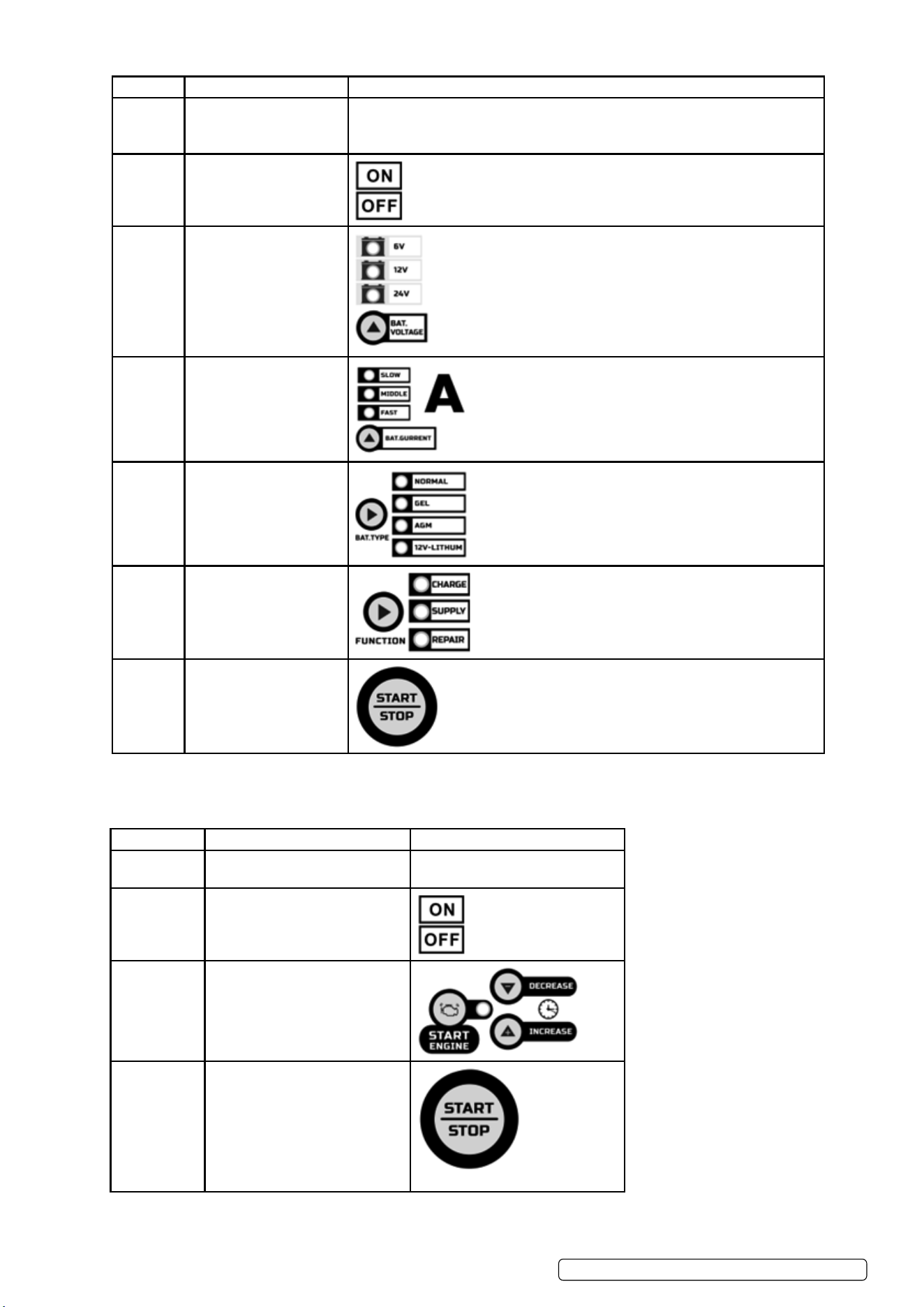
STEP NO CONNECTION STEP SELECT KEY
Step 1 Ensure battery connection. Connect 6V/12V battery to the 6V/12V terminal, and 24V battery to the 24V
terminal.
Digital display: Connected battery voltage.
Step 2 Start machine.
Step 3 Check battery voltage
type.
Step 4 Check charge current.
Step 5 Check battery type.
Step 6 Check function mode.
Step 7 Stop or start operation.
5.8. OPERATING STEPS
5.9. ENGINE START FUNCTION
5.9.1. Your battery charger can be used to jump start your car if the battery is low. Follow all safety instructions and precautions for charging
your battery. Wear complete eye protection and protective clothing. The procedures are as follows.
PROCEDURE CONNECTION SELECTION KEY
Step 1 Ensure battery connection. Digital display:Connected battery
voltage
Step 2 Start machine.
Step 3 Select the engine start button and
set the start time.
Step 4 Stop or start the operation.

Warning: Using the ENGINE START feature WITHOUT a battery installed in the vehicle will damage the vehicle’s electrical system.
5.9.2. 1. With the charger unplugged from the AC outlet, connect the charger to the battery following the instructions given in the connecting to
the battery 5.7section.
5.9.3. 2. Plug the charger AC power cord into the AC outlet. With the charger plugged in and connected to the battery and chassis, press the
ENGINE START button until the ENGINE START LED is lit.
NOTE: During extremely cold weather, or if the battery is under 2 volts, charge the battery for 5 minutes before cranking the engine.
5.9.4. Crank the engine until it starts or 3 seconds pass. If the engine does not start, wait 3 minutes before cranking again. This allows the
charger and battery to cool down.
5.9.5. If the engine fails to start, use the BOOST rate to charge for 5 minutes before attempting to crank the engine again.
5.9.6. After the engine starts, unplug the AC power cord before disconnecting the battery clamps from the vehicle.
NOTE: If the engine does turn over but never starts, there is not a problem with the starting system; there is a problem somewhere
else with the vehicle. STOP cranking the engine until the other problem has been diagnosed and corrected. During the starting
sequence listed above, the charger is set to one of three states:
5.9.7. Wait for cranking – While waiting for cranking, the digital display shows START-READY. The charger waits until the engine is actually
being cranked before delivering the amps for engine start. Press the remote button before cranking the engine immediately. If the
remote is not used, the charger will automatically detect whether engine is trying to crank.
5.9.8. Cranking – When cranking is detected, the charger will automatically deliver up to its maximum output as required by the starting
system for up to 5 times (15)seconds.
5.9.9. Cool Down – After cranking, the charger enters a mandatory 240 seconds cool down state. The remote or any button does NOT
work. The digital display indicates the remaining cool down time in seconds. It starts at 240 and counts down to 0. After 4 minutes,
the digital display will change from displaying the countdown to displaying START-READY. If using the engine starter again, please
continue to press the remote button.
5.10. VOLTAGE TESTER AND CHARGER
When rst turned on, the unit operates only as a tester, not as a charger.
If the “TEST” function is used, stop the “FUNCTION” and the corresponding working mode is turned o. Then select the “TEST”
button to detect and view the connected battery voltage and Charge level.
NOTE: The battery tester is only designed to test batteries. Testing a device with a rapidly changing voltage could yield unexpected or
inaccurate results.
5.11. ALTERNATOR CHECK
5.11.1. With the charger unplugged from the AC outlet, connect the charger to the battery, following the instructions given in previous sections.
5.11.2. Plug the charger AC power cord into the AC outlet.
5.11.3. Start the vehicle and turn on the vehicle’s headlights. Read the state on the digital display. If you get a reading “0-100%”, the alternator
is working properly. If the reading is “LO” or ”HI” , have the charging system checked by a qualied technician.
NOTE: When rst turned on, the unit operates only as a tester, not as a charger. The charger must stop charging.
5.12. CHARGING STEPS
NO. PROCEDURE DIGITAL DISPLAY LED INDICATOR CHARGING STATE
1 ANALYSING 1 ANALYSING-1
BATT-6/12/24.
CHARGING LED
lit.
Checks if battery has connected with the charger.
2 DESULPHATION CHARGING BATT-
6/12/24.
CHARGING
LED lit
Pulsing charging to remove sulphate
3 DESULPHATION CHARGING BATT-
6/12/24.
CHARGING
LED lit
Charges with gradually increasing charging current.
4 CONTROLLED
CURRENT
CHARGE
CHARGING BATT-
6/12/24
CHARGING
LED lit
Adjusts the charging current intelligently.
5 ANALYSING 2 ANALYSING-2
BATT-6/12/24
CHARGING
LED lit
Tests if the battery can absorb charge.
6 CONSTANT
OUTPUT
CHARGE
CHARGING BATT-
6/12/24
CHARGING
LED lit
Charges with constant voltage and compensates
fake full charge caused by high current charging
7 RECOVERY
CYCLE CHARGE
CHARGING BATT-
6/12/24
CHARGING
LED lit
Absorbs more charge and compensates side eect
of reduced charging current.
8 ABSORPTION CHARGING BATT-
6/12/24
CHARGING
LED lit
Charges with constant trickle current for maximum
battery voltage.
9 ANALYSING 3 ANALYSING-2
BATT-6/12/24
CHARGING
LED lit
Tests if the battery can hold charge.
10 MAINTENANCE MAINTAINING
BATT-6/12/24
CHARGING
LED lit
Continuously monitors the battery, and charges
with trickle current once the voltage is lower than
threshold
SUPERMIG 550E,750E,950E Issue 1 08/07/24
Original Language Version
© Jack Sealey Limited
© Jack Sealey Limited
Original Language Version
SUPERMIG 550E,750E,950E Issue 1 02/07/24
Sealey Group, Kempson Way, Suffolk Business Park, Bury St Edmunds, Suffolk. IP32 7AR
01284 757500 sales@sealey.co.uk www.sealey.co.uk
Note: It is our policy to continually improve products and as such we reserve the right to alter data, specifications and component parts without prior
notice.
Important: No Liability is accepted for incorrect use of this product.
Warranty: Guarantee is 12 months from purchase date, proof of which is required for any claim.
WEEE REGULATIONS
Dispose of this product at the end of its working life in compliance with the EU Directive on Waste Electrical and Electronic Equipment
(WEEE). When the product is no longer required, it must be disposed of in an environmentally protective way. Contact your local solid
waste authority for recycling information.
ENVIRONMENT PROTECTION
Recycle unwanted materials instead of disposing of them as waste. All tools, accessories and packaging should be sorted,
taken to a recycling centre and disposed of in a manner which is compatible with the environment. When the product
becomes completely unserviceable and requires disposal, drain any fluids (if applicable) into approved containers and
dispose of the product and fluids according to local regulations.
REGISTER YOUR
PURCHASE HERE
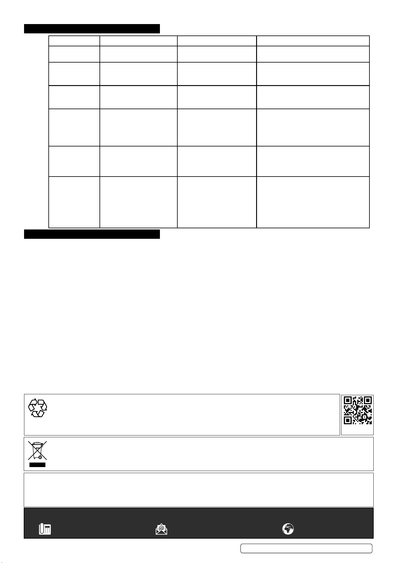
6. TROUBLESHOOTING
7. MAINTENANCE
7.1. To reduce risk of electric shock, unplug charger from outlet before attempting any maintenance or cleaning.
7.2. HANDLING
For transport make sure to only move it with the handle provided and that there are no obstacles that could cause it to stop and topple
suddenly when being pushed/pulled. If it needs to go in a vehicle to be transported to make sure it is securely fastened.
DIGITAL DISPLAY WARNING LED INDICATOR MEANING SOLUTION
E01 WARNING LED lit. The connections are reversed. Change red and black clamps or ring
terminals to the correct battery posts.
E02 WARNING LED lit. Output current reduces to 0
when temperature in charger
is too high.
DO NOT remove the AC plug immediately.
After cooling down, the battery charger will
work again.
E03 WARNING LED lit. Charging in 12V Mode for
24V battery or charging in 6V
Mode for 12V/24V battery.
Replace the battery or connect the positive
output line to the correct connector.
E04 WARNING LED lit. The battery cannot store
electric charge (dead battery)
Or battery cannot be
Recovered through
Recover Process.
Try the REPAIR MODE or Replace the
battery with a new one.
E05 WARNING LED lit. Overload in SUPPLY
Mode (will automatically
Shut down for 30 seconds as
protection).
Disconnect the external device.
0.0V WARNING LED lit. No battery connected / battery
voltage is lower than 1 volt
(dead battery) / red and
black clamps are connected
together.
1) Connect the red and black clamps or ring
terminals to battery posts.
2) Clean the battery posts.
3) Replace the battery with a new one
immediately
4) Disconnect red and black output
terminals.