Product:
600V True RMS Autoranging
Multimeter With Large Screen
WPMDMM600V15
DO NOT RETURN THIS PRODUCT TO THE STORE
If you have questions
or need assistance, please call
customer service at 888-230-4260.
User
Manual
AUTO
POWER
OFF
Safety
International Safety Symbols
This symbol adjacent to another symbol, terminal or operating device indicates
that the operator must refer to an explanation in the operating instructions to
avoid personal injury or damage to the meter.
This symbol adjacent to one or more terminals identifies them as being
associated with ranges that may, in normal use, be subjected to particularly
hazardous voltages, for maximum safety, the meter and its test leads should
not be handled when these terminals are energized.
Double insulation.
Indicates the terminal (s) so marked must not be connected to a circuit where
the voltage with respect to earth ground exceeds the maximum safety rating
of the meter.
WARNINGS
• Read, understand and follow safety rules and operating instructions in this manual
before using this meter.
• The meter’s safety features may not protect the user if not used in accordance with
the manufacturer’s instructions.
• Keep fingers away from the metal probe tips when taking measurements.
• Before changing functions using the selector switch, always disconnect the test
leads from the circuit under test.
• Comply with all applicable safety codes, use approved personal protective
equipment when working near live electrical circuits - particularly with regard to
arc-flash potential.
• Use caution on live circuits, voltages above 30V AC rms, 42V AC peak, or 60V DC
pose a shock hazard.
• Do not use if the meter or test leads appear damaged.
• Verify operation before using meter by measuring a known live voltage.
• Do not use the meter in wet or damp environments or during electrical storms.
• Do not use the meter or near explosive vapors, dust or gasses.
• Do not use the meter if it operates incorrectly, protection may be compromised.
• Do not operate meter while Low Battery warning is on, replace batteries immediately.
• Do not apply voltage or current that exceeds the meter’s maximum rated input limits.
Input Limits
Function Maximum Input
Voltage AC or DC 600V AC/DC
Frequency 600V AC/DC
10A Current AC or DC 10A/600V fast acting Fuse
mA Current AC or DC 500mA/600V fast acting Fuse
Resistance, Capacitance, Continuity,
Diode Test, Temperature
250V AC/DC
MAX
600V
Description
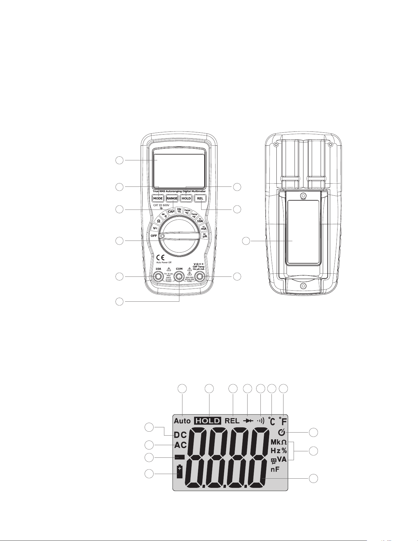
Meter Description
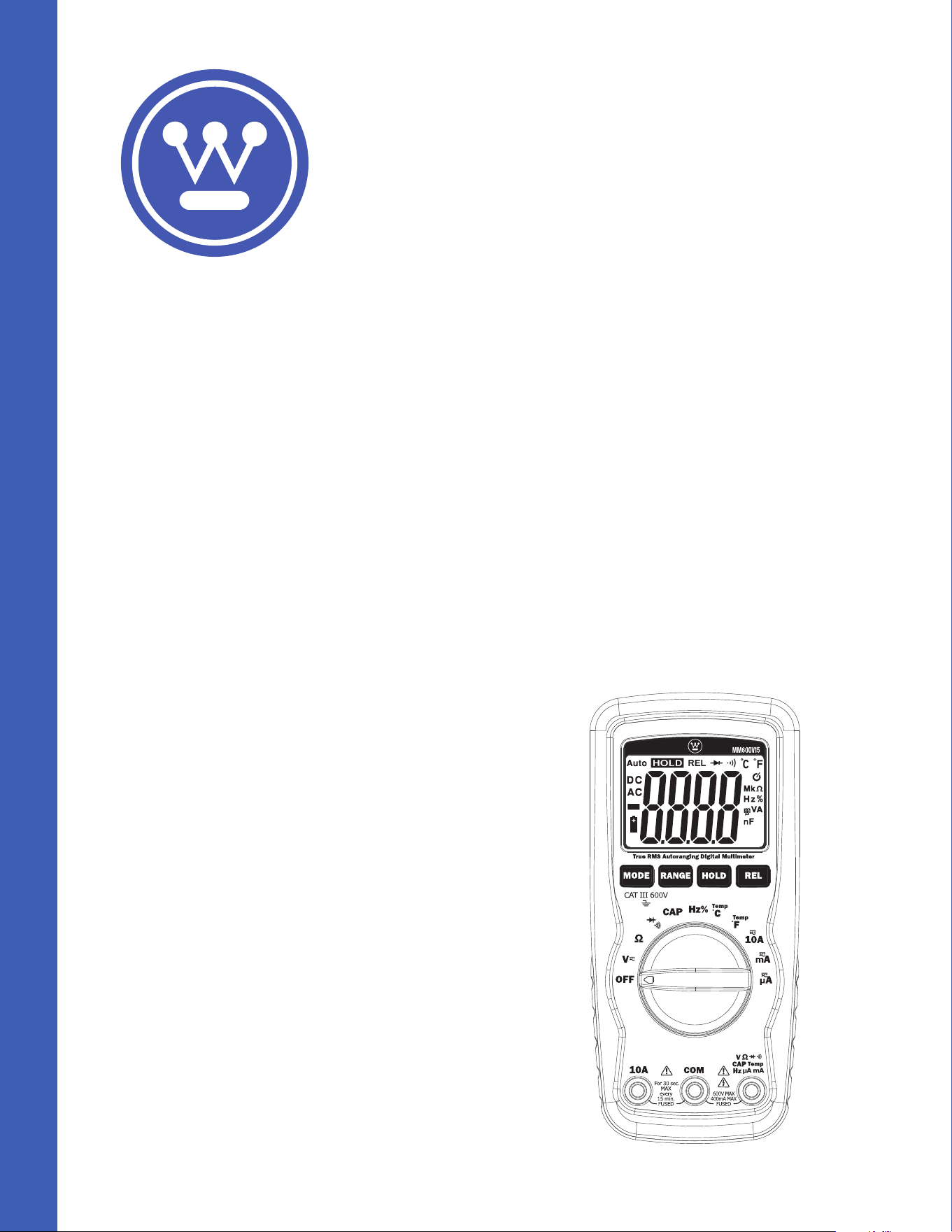
1. LCD Display
2. Function Switch
3. 10A Input Jack
4. COM Input Jack
Symbols Used on LCD Display
1. Direct Current
2. Alternating Current
3. Minus Sign
4. Low Battery
5. Auto Ranging Mode
5. Positive Input Jack
6. MODE Button
7. RANGE Button
10
1
2
3
4
5
6
7
8
9
4
5 6
7 8
9
10 11
3
2
1
12
13
14
6. Data Hold
7. Relative Mode
8. Diode Test
9. Audible Continuity
10. Degrees Celsius
11. Degrees Fahrenheit
12. Auto Power O
13. Units of Measure List
14. Measurement
Reading
8. DATA HOLD Button
9. RELATIVE Button
10. Battery Cover

Button
MODE Button
To select Diode/Continuity, DC/AC, Hz/%Duty
RANGE Button
When the meter is first turned on, it automatically goes into Autoranging. This
automatically selects the best range for the measurements being made and is generally
the best mode for most measurements. For measurement situations requiring that a
range be manually selected, perform the following:
1. Press the RANGE button. The “AUTO” display indicator will turn o.
2. Press the RANGE button to step through the available ranges until the desired test
ranges is selected.
3. Press and hold the RANGE button for 2 seconds to exit the Manual Ranging mode and
return to Auro-Ranging mode.
Data Hold Button
The Data Hold function allows the meter to “freeze” a measurement for later reference.
1. Press the Data Hold button to “freeze” the reading on the display. the indicator
“HOLD” will be appear in the display.
2. Press the Data Hold button to return to normal operation.
RELATIVE Button
The relative measurement feature allows you to make measurements relative to a stored
reference value. A reference voltage, current, etc. can be stored and measurements made
in comparison to that value. The displayed value is the dierence between the reference
value and the measured value.
1. Perform any measurement as described in the operating instructions.
2. Press the RELATIVE button to store the reading in the display and the ”REL” indicator
will appear on the display.
3. The display will now indicate the dierence between the stored value and the
measured value.
4. Press the RELATIVE button to return to normal operation.
Operation
WARNING: Risk of electrocution. High-voltage circuits, both AC and DC, are very dangerous
and should be measured with great care.
• ALWAYS turn the function switch to the OFF position when the meter is not in use.
This meter has Auto OFF that automatically shuts the meter OFF if 15 minutes
elapse between uses.
• If “OL” appears in the display during a measurement, the value exceeds the range you
have selected. Change to a higher range.
NOTE: On some low AC and DC voltage ranges, with the test leads not connected to a
device, the display may show a random, changing reading. This is normal and is caused by
the high-input sensitivity. The reading will stabilize and give a proper measurement when
connected to a circuit.
DC Voltage Measurements
CAUTION: Do not measure DC voltages if a motor on the circuit is being switched ON or OFF.
Large voltage surges may occur that can damage the meter.
1. Set the function switch to the VDC position (“mV” will appear in the display).
2. Insert the black test lead banana plug into the negative (COM) jack and the red test
lead banana plug into the positive (V) jack.
3. Touch the test probe tips to the circuit under test. Be sure to observe the correct
polarity (red lead to positive, black lead to negative).
4. Read the voltage in the display. The display will indicate the proper decimal point
and value. If the polarity is reversed, the display will show (-) minus before the value.
AC Voltage Measurements
WARNING: Risk of Electrocution. The probe tips may not be long enough to contact the live
parts inside some 240V outlets for appliances because the contacts are recessed deep in
the outlets. As a result, the reading may show 0 volts when the outlet actually has voltage
on it. Make sure the probe tips are touching the metal contacts inside the outlet before
assuming that no voltage is present.
CAUTION: Do not measure AC voltages if a motor on the circuit is being switched ON or OFF.
Large voltage surges may occur that can damage the meter.
1. Set the function switch to the VAC position.
2. Insert the black test lead banana plug into the negative (COM) jack and the red test
lead banana plug into the positive (V) jack.
3. Touch the test probe tips to the circuit under test.
4. Read the voltage in the display. The display will indicate the proper decimal point,
value and symbol (AC, V, etc.).
DC Current Measurements
CAUTION: Do not make current measurements on the 10A scale for longer than 30 seconds.
Exceeding 30 seconds may cause damage to the meter and/or the test leads.
1. Insert the black test lead banana plug into the negative (COM) jack.
2. For current measurements up to 400µA DC, set the function switch to the µA
position and insert the red test lead banana plug into the (mA/µA) jack.
3. For current measurements up to 400mA DC, set the function switch to the mA
range and insert the red test lead banana plug into the (mA/µA) jack.
4. For current measurements up to 10A DC, set the function switch to the 10A position
and insert the red test lead banana plug into the (10A) jack.
5. Press the MODE Button until “DC” appears in the display.
6. Remove power from the circuit under test, then open up the circuit at the point
where you wish to measure current.
7. Touch the black test probe tip to the negative side of the circuit. Touch the red test
probe tip to the positive side of the circuit.
8. Apply power to the circuit.
9. Read the current in the display. The display will indicate the proper decimal point,
value and symbol.
Current Measurements
WARNING: To avoid electric shock, do not measure AC current on any circuit whose
voltage exceeds 250V AC.
CAUTION: Do not make current measurements on the 10A scale for longer than 30 seconds.
Exceeding 30 seconds may cause damage to the meter and/or the test leads.
1. Insert the black test lead banana plug into the negative (COM) jack.
2. For current measurements up to 4000µA AC, set the function switch to the µA
position and insert the red test lead banana plug into the (mA/µA) jack.
3. For current measurements up to 400mA AC, set the function switch to the mA
range and insert the red test lead banana plug into the (mA/µA) jack.
4. For current measurements up to 10A AC, set the function switch to the 10A position
and insert the red test lead banana plug into the 10A jack.
5. Press the MODE Button until “AC” appears in the display.
6. Remove power from the circuit under test, then open up the circuit at the point
where you wish to measure current.
7. Touch the black test probe tip to the negative side of the circuit. And touch the red
test probe tip to the positive side of the circuit.
8. Apply power to the circuit.
9. Read the current in the display. The display will indicate the proper decimal point,
value and symbol.
Resistance Measurements
WARNING: To avoid electric shock, disconnect power to the unit under test and discharge
all capacitors before taking any resistance measurements. Remove the batteries and
unplug the line cords.
1. Set the function switch to the Ω position.
2. Insert the black test lead banana plug into the negative (COM) jack and the red test
lead banana plug into the positive (Ω) jack.
3. Touch the test probe tips across the circuit or part under test. It is best to
disconnect one side of the part under test so the rest of the circuit will not interfere
with the resistance reading.
4. Read the resistance in the display. The display will indicate the proper decimal point,
value and symbol.
Frequency Measurement
1. Set the function switch to the FREQ position.
2. Insert the black test lead banana plug into the negative (COM) jack and the red test
lead banana plug into the positive (Hz) jack.
3. Touch the test probe tips to the circuit under test.
4. Read the frequency in the display. The digital reading will indicate the proper decimal
point, symbols (Hz, kHz) and value.
Capacitance Measurements
WARNING: To avoid electric shock, disconnect power to the unit under test and discharge
all capacitors before taking any capacitance measurements. Remove the batteries and
unplug the line cords.
1. Set the function switch to the CAP position. (“nF” and a small value will appear in the
display).
2. Insert the black test lead banana plug into the negative (COM) jack and the red test
lead banana plug into the positive (CAP) jack.
3. Touch the test leads to the capacitor to be tested. The display will indicate the proper
decimal point, value and symbol.
Temperature Measurements
WARNING: To avoid electric shock, disconnect both test probes from any source of
voltage before making a temperature measurement.
1. If you wish to measure temperature in °C, set the function switch to the °C range. If
you wish to measure temperature in °F, set the function switch to the °F range.
2. Insert the type K thermocouple probe black test lead banana plug into the negative
COM jack and the red test lead banana plug into the positive Temp jack.
3. Touch the Temperature Probe head to the part whose temperature you wish to
measure. Keep the probe touching the part under test until the reading stabilizes
(about 30 seconds).
4. Read the temperature in the display. The digital reading will indicate the proper
decimal point and value.
WARNING: To avoid electric shock, be sure the thermocouple has been removed before
changing to another measurement function.
Continuity Check
WARNING: To avoid electric shock, never measure continuity on circuits or wires that have
voltage on them.
1. Set the function switch to the position.
2. Insert the black lead banana plug into the negative (COM) jack and the red test lead
banana plug into the positive (Ω) jack.
3. Press the MODE Button until the symbol appears in the display.
4. Touch the test probe tips to the circuit or wire you wish to check. If the resistance is
less than approximately 50Ω, the audible signal will sound. The display will also
show the actual resistance.
Diode Test
WARNING: To avoid electric shock, do not test any diode that has voltage on it.
1. Set the function switch to position.
2. Press the MODE Button until the symbol appears in the display.
3. Insert the black test lead banana plug into the negative (COM) jack and the red test
lead banana plug into the positive (Ω) jack.
4. Touch the test probe tips to the diode or semiconductor junctionyou wishtotest.
Note the meter reading.
5. Reverse the probe polarity by switching probe position. Note this reading.
6. The diode or junction can be evaluated as follows:
A. If one reading shows a value and the other reading shows OL, the diode is good.
B. If both readings show OL, the device is open.
C. If both readings are very small or 0, the device is shorted.
NOTE: The value indicated in the display during the diode check is the forward voltage.

Replacing the Battery
WARNING: To avoid electric shock, disconnect the test leads from any source of voltage
before removing the battery door.
1. Disconnect the test leads from the meter.
2. Open the battery cover by loosening the screw using a Phillips head screwdriver.
3. Insert the battery into battery holder, observing the correct polarity.
4. Put the battery cover back in place. Secure with the two screws.
WARNING: To avoid electric shock, do not operate the meter until the battery door is in
place and fastened securely.
NOTE: If your meter does not work properly, check the fuses and battery to make sure that
they are still good and that they are properly inserted.
Replacing The Fuses
WARNING: To avoid electric shock, disconnect the test leads from any source of voltage
before removing the fuse cover.
1. Loosen the Phillips screws on the fuse cover.
2. Carefully remove the old fuse using a non-metallic tool to avoid damage or
accidental contact.
3. Gently remove the old fuse and install the new fuse into the holder.
4. Insert the new fuse into the holder, ensuring it is securely in place and matches the
specified type and rating.
5. Replace and secure the fuse cover.
WARNING: To avoid electric shock, do not operate your meter until the fuse cover is in
place and fastened securely.
Care and Maintenance
• Do not immerse the instrument in water.
• Ensure the multimeter is powered o, then clean it gently using a dry, lint-free cloth
• Do not use aggressive cleaning agents or solutions.
• Do not mix dierent types of batteries such as alkaline, carbon-zinc, or rechargeable
batteries.
• Handle the instrument with care.
• Please take out the battery when the instrument is not used for a long time.
* Keep it away from high temperatures and humidity. If the meter has been stored in
extreme conditions beyond the limits specified in the General Specifications section,
allow it to stabilize under normal operating conditions before use.
Specifications
Technical Specifications
Accuracy is given at 18 to 28°C (65 to 83°F), Less than 70 % RH.
AC Voltage
Auto-ranging
except 400mV
400.0mV
4.000V
40.00V
400.0V
600V
0.1mV
1mV
10mV
100mV
1V
±(1.5% + 15 digits)
±(1.2% + 3 digits)
±(1.5% + 3 digits)
±(2.0% + 4 digits)
Input Impedance: 10MΩ. Frequency Range: 50 to 60Hz.
Maximum Input: 600V DC or 600V AC RMS.
All AC voltage ranges are specified from 5% of range to 100% of range;
AC voltage bandwidth: 50 to 400Hz(sine), 50 to 60Hz (all wave).
Input Impedance: 10MΩ. Maximum Input: 600V DC or 600V AC RMS.
DC Voltage
Auto-ranging
Function Accuracy ± (% of reading)Range Resolution
Function Accuracy ± (% of reading)Range Resolution
Function Accuracy ± (% of reading)Range Resolution
400.0mV
4.000V
40.00V
400.0V
600V
0.1mV
1mV
10mV
100mV
1V
±(0.5% + 2 digits)
±(1.2% + 2 digits)
±(1.5% + 2 digits)
Overload Protection: 0.5A / 250V and 10A / 250V Fuse.
Maximum Input: 400mA DC or 400mA AC RMS on µA/mA ranges.
10A DC or AC RMS on 10A range.
DC Current
Auto-ranging
for µA and mA
400.0µA
4000µA
40.00mA
400.0mA
10A
0.1µA
1µA
10µA
100µA
10mA
±(1.0% + 3 digits)
±(1.5% + 3 digits)
±(2.5% + 5 digits)
Function Accuracy ± (% of reading)Range Resolution
Overload Protection: 0.5A / 250V and 10A / 250V Fuse.
Frequency Ranger: 50 to 400Hz.
Maximum Input: 400mA DC or 400mA AC RMS on µA/mA ranges.
10A DC or AC RMS on 10A range.
All AC Current ranges are specified from 5% of range to 100% of range;
AC Current bandwidth: 50 to 400Hz(sine), 50 to 60Hz (all wave).
AC Current
Auto-ranging
for µA and mA
400.0µA
4000µA
40.00mA
400.0mA
10A
0.1µA
1µA
10µA
100µA
10mA
±(1.5% + 5 digits)
±(1.8% + 5 digits)
±(3.0% + 7 digits)
Function Accuracy ± (% of reading)Range Resolution
Input Protection: 250V DC or 250V AC RMS.
Capacitance
Auto-ranging
40.00nF
400.0nF
4.000µF
40.00µF
4.000mF
0.01nF
0.1nF
1nF
10nF
0.001mF
±(5.0% + 20 digits)
±(3.0% + 5 digits)
±(5.0% + 5 digits)
Function Accuracy ± (% of reading)Range Resolution
Input Protection: 250V DC or 250V AC RMS.
Resistance
Auto-ranging
400.0Ω
4.000kΩ
40.00kΩ
400.0kΩ
4.000MΩ
40.00MΩ
0.1Ω
1Ω
10Ω
100Ω
1kΩ
10kΩ
±(1.2% + 4 digits)
±(1.0% + 2 digits)
±(1.2% + 2 digits)
±(2.0% + 3 digits)
Function Accuracy ± (% of reading)Range Resolution
Sensitivity: >0.5V RMS while <=1MHz;
Sensitivity: >3V RMS while >1MHz;
Overload Protection: 250V DC or AC RMS.
Frequency
Auto-ranging
9.999Hz
99.99Hz
999.9Hz
9.999kHz
99.99kHz
999.9kHz
9.999MHz
0.001Hz
0.01Hz
0.1Hz
1Hz
10Hz
100Hz
1kHz
±(1.5% + 5 digits)
±(1.2% + 3 digits)
±(1.5% + 4 digits)
Function
Duty Cycle
AccuracyRange Resolution
0.1% to 99.9% 0.1% ±(1.2% + 2 digits)
Function
Temperature
AccuracyRange Resolution
-20 to 760°C
-4 to 1400°F
1°C
1°F
±(3% + 5°C)
±(3% + 9°F)
Puise width: >100µs, <100ms
Frequency width: 5Hz to 150kHz
Sensitvity: >0.5V RMS
Overload Protection: 250V DC or AC RMS.
Function
Diode Test
AccuracyRange Resolution
0.3mA Typical 1mV ±(10% + 5 digits)
Open Circuit Voltage: 3.2V DC typical;
Overload Protection: 250V DC or AC RMS.
Sensor: Type K Thermocouple
Overload Protection: 250V DC or AC RMS.
Audible Continuity
Audible threshold: Less than 50Ω,Test current: <0.35mA
Overload Protection: 250V DC or AC RMS.

General Specifications
Instrument Complies with:
Insulation:
Overvoltage Category:
Display:
Polarity:
Overrange:
Low Battery Indication:
Measurement Rate:
AC Response:
Auto Power O:
Operating Environment:
Storage Temperature:
Operating Altitude:
Pollution Degree:
Power:
UL 61010-1 & CSA C22.2 No 61010-1 Safety Requirements
For Electrical Equipment For Measurement, Control, And
Laboratory.
Class2, Double insulation.
CAT III 600V.
4000 counts LCD display with function indication.
Automatic, (-) negative polarity indication.
“OL” mark indication.
The “ ” is displayed when the battery voltage drops
below the operating level.
2 times per second, nominal.
True RMS
Meter automatically shuts down after approx. 15 minutes
of inactivity.
0 to 50°C (32 to 122°F) at < 70% relative humidity.
-20 to 60°C (-4 to 140°F) at < 80% relative humidity.
2000m
2
One 9V battery, NEDA 1604, IEC 6F22.

2-Year Warranty
If your product fails due to defects in materials or workmanship, we will replace it.
This warranty is valid only for the original end-user purchaser of the product.
Exclusions:
• The warranty is non-transferable.
• For details, contact Customer Care at (888) 230-4260 or send us a mail at
• This warranty applies exclusively to products purchased directly from us or our
authorized sellers. Products bought from unauthorized sellers, including
unapproved online platforms, may not be covered unless prohibited by law.
• We reserve the right to deny warranty claims for items purchased from
unauthorized sellers.
Legal Rights:
This warranty provides you with specific legal rights, and you may have additional
rights that vary by state or country. Proof of purchase indicating the date and place of
purchase may be required.
Limitations:
This limited warranty replaces all other express warranties. Any implied warranties,
including merchantability or fitness for a particular purpose, are limited to the
duration of this warranty. We are not liable for incidental or consequential damages.
Note: Some states or countries do not allow limitations on the duration of implied
warranties or exclusions of certain damages, so these limitations may not apply to you.
This guarantee applies only to products purchased from us or authorized sellers unless
prohibited by law. We may reject claims for items bought from unauthorized sellers,
including unapproved online platforms.
For more details or to confirm if a seller is authorized, contact Customer Care at
(888) 230-4260 or email us at [email protected]
Disposal / Recycle
Do not dispose of the equipment and its accessories in the trash. Ensure proper disposal in
compliance with local regulations. For more information, visit www.epa.gov/recycle.

www.westinghouse.com
Service Number 888-230-4260
and Westinghouse are trademarks of Westinghouse Electric Corporation.
Used under license by Bramli USA Inc.