1-800-523-7138
Continental Refrigerator
A Division of National Refrigeration
& Air Conditioning Products, Inc.
539 Dunksferry Road
Bensalem, PA 19020-5908
P 215-244-1400
F 215-244-9579
www.continentalrefrigerator.com
OPERATIONS MANUAL
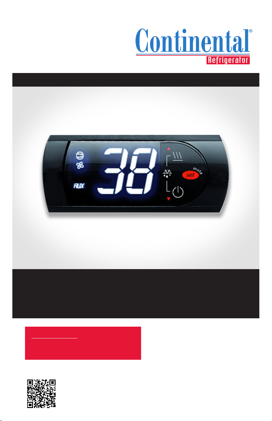
easy Electronic Control
SCAN this code
to download manual
IMPORTANT NOTE: Any unauthorized
changes to Tech Service Parameters may
damage equipment and void warranty.
FOR REFRIGERATORS, FREEZERS AND WARMERS


OPERATIONS MANUAL
easy ELECTRONIC CONTROL FOR REFRIGERATORS, FREEZERS AND WARMERS
Page
Electronic Control Display and Button Description 4
Initial Sequence of Operation 4
Electronic Control User Level Parameters 5
How to Change the Set-Point 6
How to Initiate a Manual Defrost 7
How to Change the Defrost Interval 8
How to Turn the AUX (Anti-Condensate) Heaters ON/OFF 9
How to Calibrate the Temperature Display 10
How to Change the High and Low Temperature Alarm Set Points 11
How to Silence the Alarm Beeper 12
How to Switch the Controller OFF/ON 13
How to Lock/Unlock the Controller Keypad 14
How to Access the Tech Service Parameters 15
How to See the Evaporator Probe Temperature 16
How to Activate EZY Set Parameters/Restore Factory Settings 17
Control Troubleshooting 18
Electronic Control Error Codes 20
Probe Resistance Values 20
How to Remove the Electronic Control 21
Split Control Parameters 22
Self-Contained Control Parameters 24
Warmer Control Parameters 26
4
OPERATIONS MANUAL
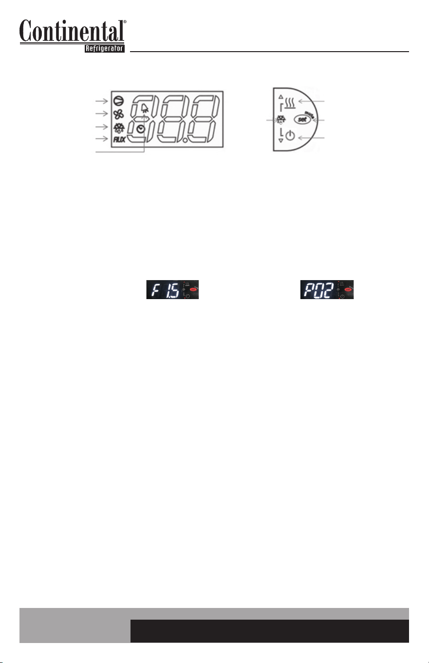
ELECTRONIC CONTROL DISPLAY AND BUTTON DESCRIPTION
INITIAL SEQUENCE OF OPERATION
1. Cabinet is plugged in.
2. The control will cycle the compressor on and off determined by the Set-Point and Differential
Temperatures. (If the Set-Point needs to be changed, please see instructions on Page 6).
3. The control may be preprogrammed to initiate a defrost by time interval. (If additional defrost
cycles are needed or a manual defrost is required due to conditions, please see the instructions
on Pages 7 & 8).
The control icons shown above will be illuminated when the associated function is active. If the icons
are flashing, it means the function will be activated after the controller delays are finished.
The easy control has a “3” button interface.
• The “AUX HTRS/UP” button is used for activation or deactivation of the auxiliary anti-condensate
heaters or for increasing values.
• The “SET/MUTE” button is used to lock in a new value or to silence the alarm beeper.
• The “POWER/DOWN” button is used to turn the unit on/off or for decreasing values.
• Press the UP and DOWN buttons simultaneously to put into a manual defrost.
a. The Set-Point is the preprogrammed temperature which shuts off the compressor.
b. The Differential is the preprogrammed temperature that is added to the Set-Point
temperature that will start the compressor.
a. During defrost, the defrost icon will appear in the display and the compressor will turn
off until a preprogrammed temperature or time is reached. During this time for freezers
only, evaporator fan(s) will also turn off and the defrost heater will be energized.
b. After a preprogrammed evaporator temperature or time has been reached, there may
be a short delay for both the compressor and evaporator fan(s) to restart.
c. After the defrost cycle is completed, the control will resume normal operation.
a. Display will show “F’ and the firmware version, then will show “P” and the parameter version.
b. Display will then show current cabinet temperature.
c. The compressor icon and the auxiliary heater icon may flash for a period of time,
indicating normal delayed start-up.
d. After the start-up delay, the compressor and evaporator fan(s) will start if the control is
calling for cooling. The fans may pulse on and off when the compressor is off to conserve
energy.
EXAMPLE: Set-Point is 36°F and the Differential is 4°F
The compressor and condenser fan(s) will cycle off at 36°F and back on at 40°F.
COMPRESSOR
EVAP FAN
DEFROST
AUX HTRS
ALARM
AUX HTRS (UP)
SET (MUTE)
POWER (DOWN)
DEFROST
2 BUTTONS
If you have any questions, please contact the Technical Service Department.
Phone: (800) 523-7138 • Email: [email protected]
5
easy ELECTRONIC CONTROL FOR REFRIGERATORS, FREEZERS AND WARMERS
OPERATIONS MANUAL
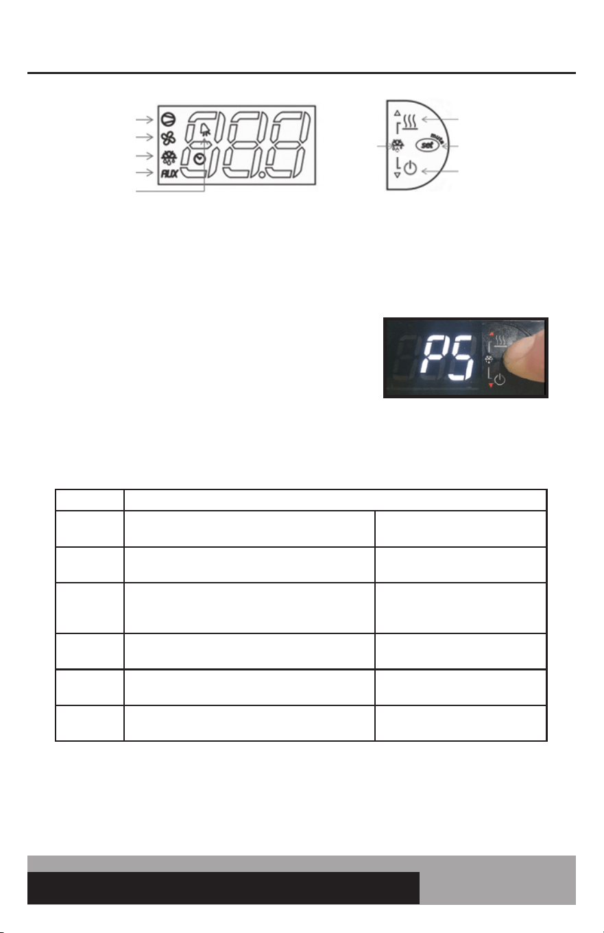
ELECTRONIC CONTROL USER LEVEL PARAMETERS
User level parameters give the end user the option to customize their control.
TO ACCESS AND CHANGE USER LEVEL PARAMETERS
• Press and HOLD the “SET” button until “PS” appears
flashing in the display. RELEASE the “SET” button.
You now have access to the User Parameters.
• Use the “UP” or “DOWN” button to go to the
parameter.
• Press and RELEASE the “SET” button to access
the parameter settings.
• Use the “UP” or “DOWN” button to change the
parameter value.
• Press and HOLD the “SET” button for 5 seconds to lock in the new value.
• When the display returns back to cabinet temperature, RELEASE the “SET” button.
Parameter Description
PS
Password used to access tech service parameters
Used by service personnel to
access tech service parameters
/C1
Display probe offset value
Used to calibrate the
temperature display
dl
Defrost interval
Hours between defrost. The
lower the value, the more
defrosts per day.
AL
Low temperature alarm setting
Used to set the low temperature
alarm value.
AH
High temperature alarm setting
Used to set the high temperature
alarm value.
H4
Alarm beeper
0: Beeper active
1: Beeper not active
For a more detailed description on how to access and change these parameter values, there are
individual pages in this manual with detailed instructions.
COMPRESSOR
EVAP FAN
DEFROST
AUX HTRS
ALARM
AUX HTRS (UP)
SET (MUTE)
POWER (DOWN)
DEFROST
2 BUTTONS
6
OPERATIONS MANUAL
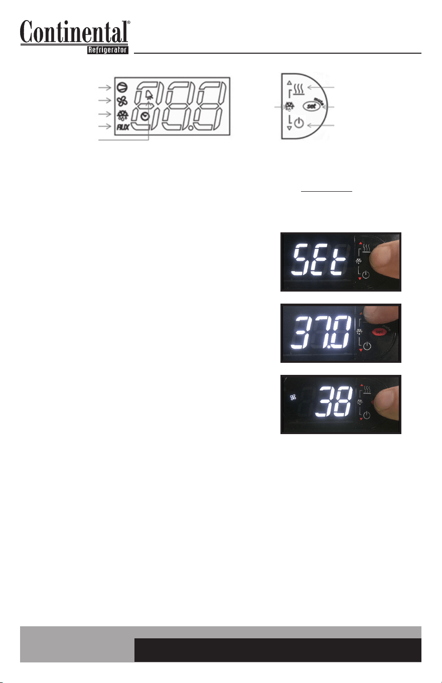
HOW TO CHANGE THE SET-POINT
The set-point is the temperature at which the compressor will shut off. Please note the set-point
is not the cabinet holding temperature. Please refer to Page 4 for an explanation of set-point and
differential.
1. Press and HOLD the “SET” button until the current
set-point begins flashing. RELEASE the “SET” button.
2. Press the “UP” or “DOWN” button to adjust to the
new set-point value. Here the “UP” button was pressed
to change the set-point from 36°F to 37°F.
3. Press and RELEASE the “SET” button to lock in the
new set-point. The control will now resume normal
operation with the new set-point.
COMPRESSOR
EVAP FAN
DEFROST
AUX HTRS
ALARM
AUX HTRS (UP)
SET (MUTE)
POWER (DOWN)
DEFROST
2 BUTTONS
7
easy ELECTRONIC CONTROL FOR REFRIGERATORS, FREEZERS AND WARMERS
OPERATIONS MANUAL
HOW TO INITIATE A MANUAL DEFROST
A one-time additional defrost may be necessary to clear accumulated ice from the evaporator coil.
1. Press and HOLD the “UP” and “DOWN” buttons
simultaneously.
2. After 5 seconds, the defrost icon will illuminate.
RELEASE the defrost buttons.
Defrost will terminate when the pre programmed temperature or time duration has been reached.
The manual defrost can also be manually terminated by pressing and holding the “Up” and “Down”
button for 5 seconds.
COMPRESSOR
EVAP FAN
DEFROST
AUX HTRS
ALARM
AUX HTRS (UP)
SET (MUTE)
POWER (DOWN)
DEFROST
2 BUTTONS
8
OPERATIONS MANUAL
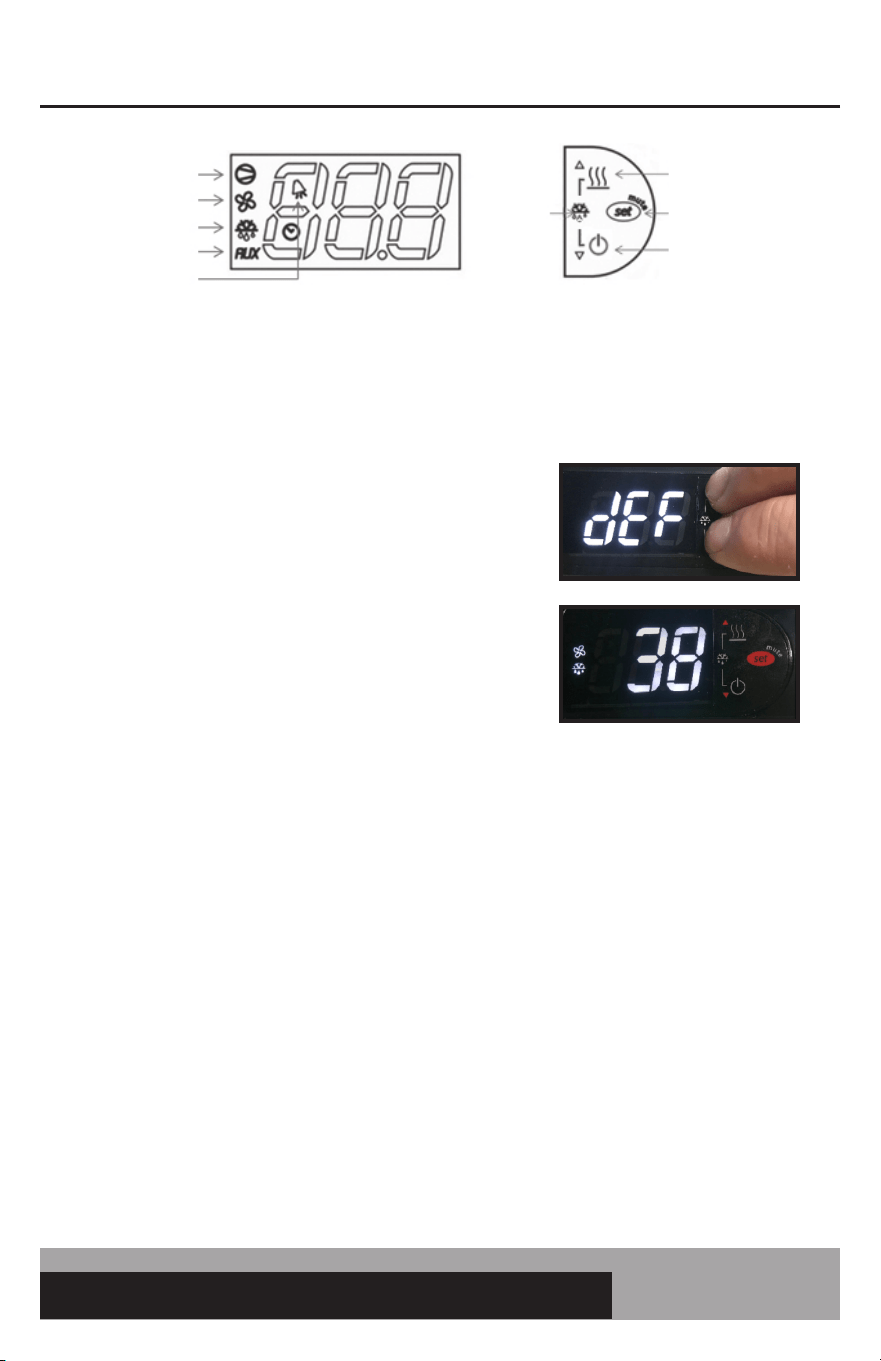
HOW TO CHANGE THE DEFROST INTERVAL
This is used to increase or decrease the frequency of defrosts. If the interval is set at “8”, a defrost will
occur every 8 hours. If you need more defrosts, lower this value.
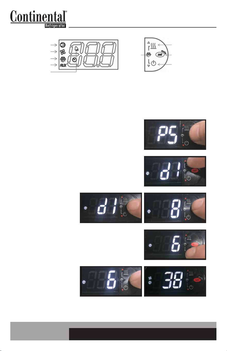
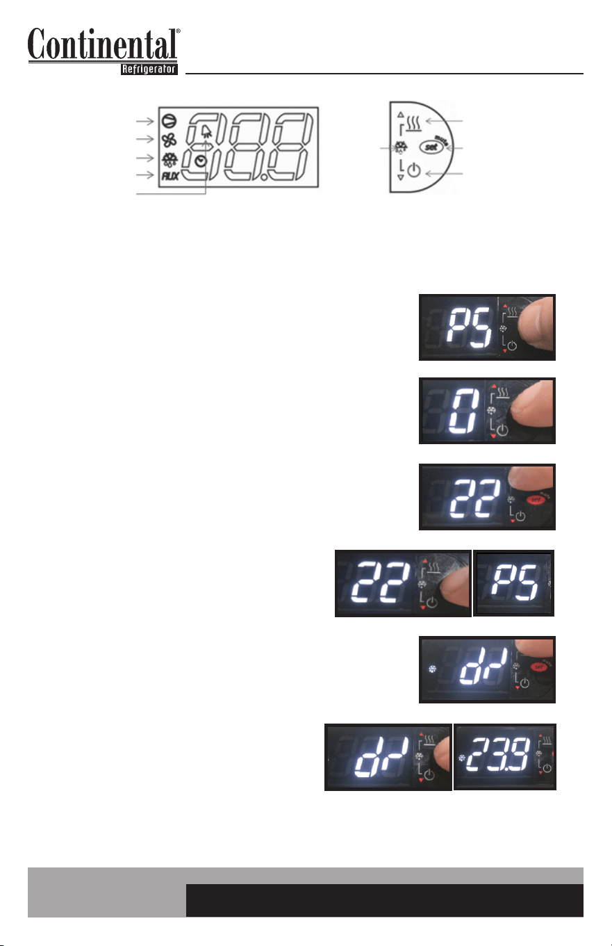
1. Press and HOLD the “SET” button until “PS” appears
flashing in the display. RELEASE the “SET” button.
2. Press the “UP” button until “dI” appears (defrost interval).
RELEASE the “UP” button.
3. Press and RELEASE
the “SET” button.
The current defrost
interval will appear
in the display.
4. Press the “UP” or “DOWN” button to adjust to the new
defrost interval. Here the “DOWN” button was pressed
to change the interval from every 8 hours to every 6 hours.
5. Press and HOLD the
“SET” button to lock in
this new value. When
the display returns back
to cabinet temperature,
RELEASE the “SET”
button.
COMPRESSOR
EVAP FAN
DEFROST
AUX HTRS
ALARM
AUX HTRS (UP)
SET (MUTE)
POWER (DOWN)
DEFROST
2 BUTTONS
9
easy ELECTRONIC CONTROL FOR REFRIGERATORS, FREEZERS AND WARMERS
OPERATIONS MANUAL
HOW TO TURN THE AUX (ANTI-CONDENSATE) HEATERS ON/OFF
Anti-condensate heaters are located around the door to eliminate condensation. In order to save energy
these heaters can be turned off.
1. To see the current state of the AUX (anti-condensate)
heaters, press and HOLD the AUX HTR button for 1
second. RELEASE the AUX HTR button. The display will
show the current state of the heater when the button is
pressed. In this case the heaters are currently ON.
2. To change the current state of the AUX Heaters, press
and HOLD the AUX HTR button. The display will show
the current state of heater operation. After 5 seconds,
the heater will switch to the opposite state and the
display will return to displaying the cabinet temperature.
RELEASE the button.
The control has a built in energy saving feature for the aux (anti-condensate heaters). When in
the ON position, the “AUX” icon may not illuminate indicating the AUX heaters are not currently
energized. The control will automatically energize the AUX heaters when the conditions require
these heaters to be activated.
COMPRESSOR
EVAP FAN
DEFROST
AUX HTRS
ALARM
AUX HTRS (UP)
SET (MUTE)
POWER (DOWN)
DEFROST
2 BUTTONS
10
OPERATIONS MANUAL
HOW TO CALIBRATE THE TEMPERATURE DISPLAY
The controller temperature display can be calibrated if required. Before attempting to calibrate the tem-
perature display, check display by placing a pre-calibrated temperature sensing device in center of the
refrigerated compartment and keep doors closed for at least 15 minutes. Temperature display should
read same temperature as sensing device, within +/-2°F. If not, follow these instructions to calibrate.
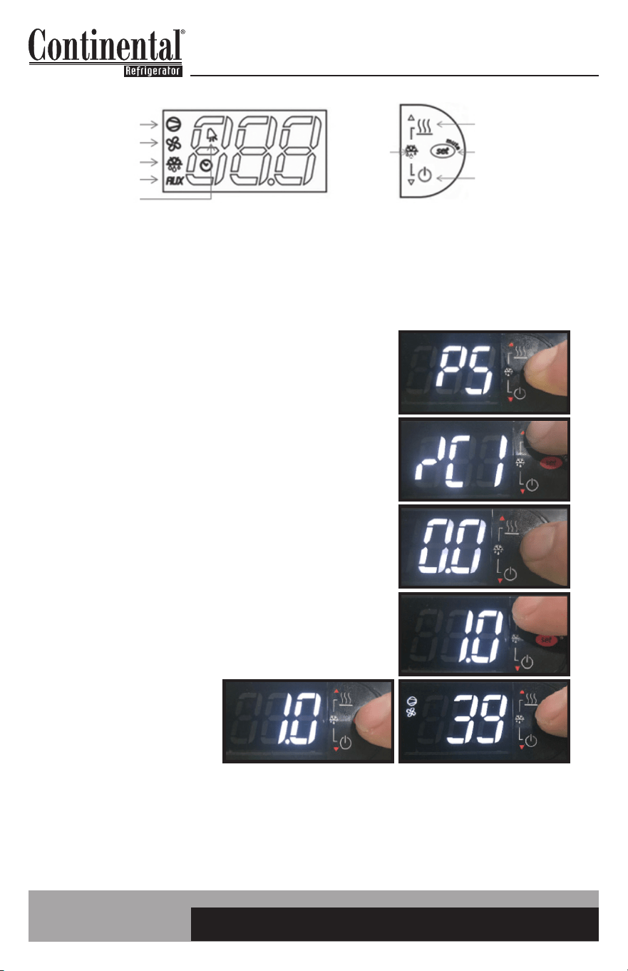
1. Press and HOLD the “SET” button until “PS” appears
flashing in the display. RELEASE the “SET” button.
2. Press the “UP” button until “/C1” appears in the display.
RELEASE the “UP” button.
3. Press and RELEASE the “SET” button. The current value
of the offset will appear in the display. In this case, the
offset is set at 0.0
4. Press the “UP” button to increase or the “DOWN” button
to decrease the offset value. In this case the “UP” button
was pressed to increase the offset to 1.0
5. Press and HOLD the
“SET” button for 5
seconds to confirm
and save the new value.
When complete, the
current temperature will
be displayed. RELEASE
the “SET” button
For example: If a sensing device in the cabinet reads 38° and control display shows 41°, follow
steps above and decrease current offset value by 3 (if current offset value was 0, change to: -3.0
and save.)
COMPRESSOR
EVAP FAN
DEFROST
AUX HTRS
ALARM
AUX HTRS (UP)
SET (MUTE)
POWER (DOWN)
DEFROST
2 BUTTONS
11
easy ELECTRONIC CONTROL FOR REFRIGERATORS, FREEZERS AND WARMERS
OPERATIONS MANUAL
HOW TO CHANGE THE HIGH AND LOW TEMPERATURE ALARM SET POINTS
The controller has a high and low alarm set point. These values can be modified per the end user
requirements. There is a pre programmed time delay for the alarm to activate to eliminate nuisance
alarms.
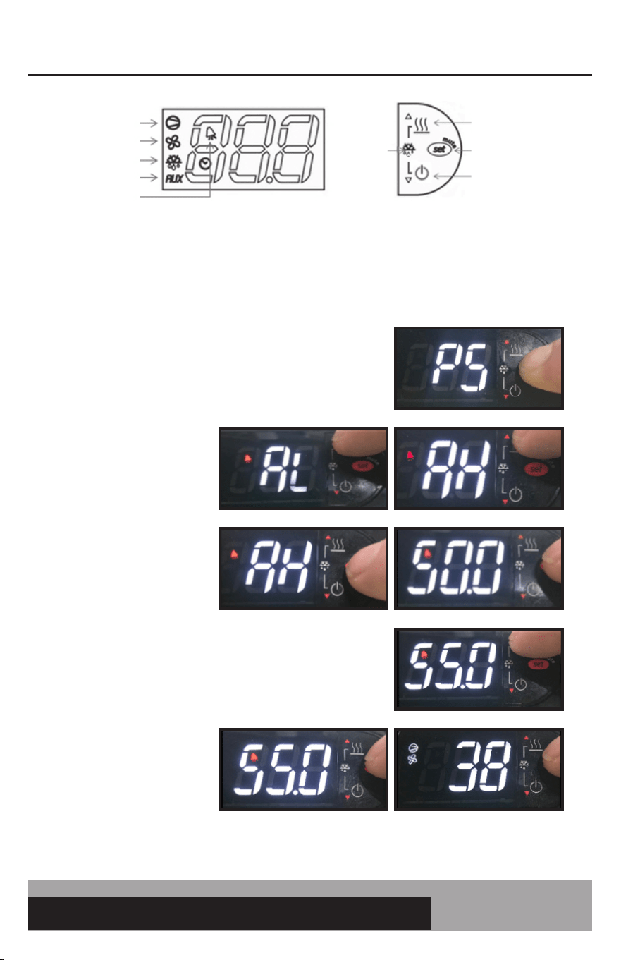
1. Press and HOLD the “SET” button until “PS” appears
flashing in the display. RELEASE the “SET” button.
2. Press the “UP” button
until “AL” (Low Alarm
Setting) or “AH” (High
Alarm Setting) appears
in the display. RELEASE
the “UP” button.
3. Press and RELEASE
the “SET” button. The
current alarm setting
will be shown.
4. Press the “UP” or “DOWN” to get to the new
alarm set-point. Release the button. In this case
the “UP” button was pressed until the new set point
of 55.0°F was reached.
5. Press and HOLD the
“SET” button for 5
seconds to confirm
and save the new value.
When complete, the
current temperature will
be displayed. RELEASE
the “SET” button.
COMPRESSOR
EVAP FAN
DEFROST
AUX HTRS
ALARM
AUX HTRS (UP)
SET (MUTE)
POWER (DOWN)
DEFROST
2 BUTTONS
12
OPERATIONS MANUAL
HOW TO SILENCE THE ALARM BEEPER
When a high or low temperature alarm is activated AL (low) or AH (high) will flash in the display
alternating with the current cabinet temperature. At the same time, a beeper will sound. To silence the
beeper for the active alarm just press and release the “SET/MUTE” button. To silence the beeper for all
future alarms follow this procedure.
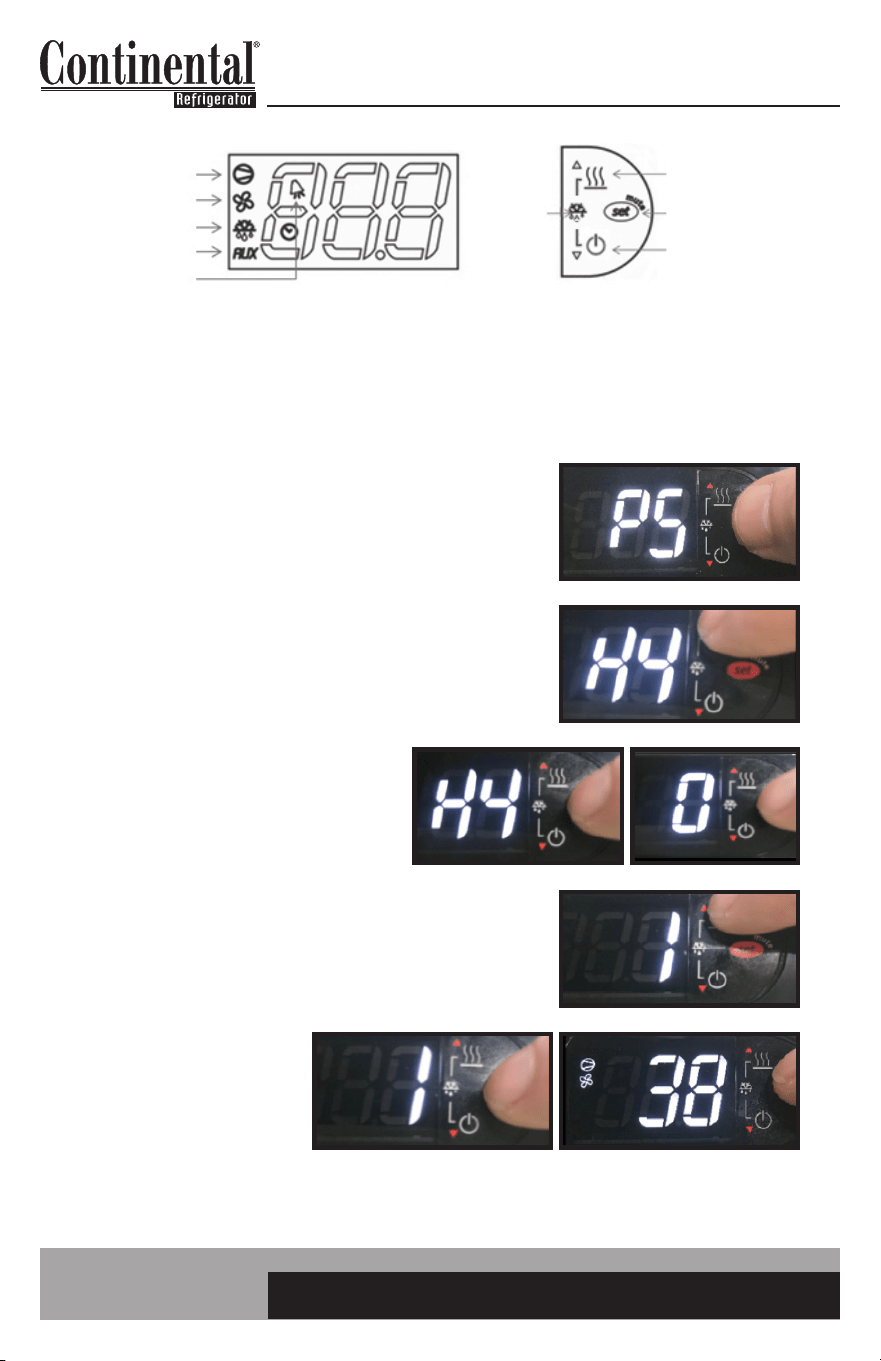
1. Press and HOLD the “SET” button until “PS” appears
flashing in the display. RELEASE the “SET” button.
2. Press the “UP” button until “H4” appears in the display.
RELEASE the “UP” button.
3. Press and RELEASE the “SET” button.
“0” will appear in the display. 0: alarm
beeper active.
4. Press and RELEASE the “UP” button. 1 will appear
in the display. 1: alarm beeper silenced.
5. Press and HOLD the
“SET” button for 5
seconds to confirm and
save the new value.
When complete, the
current temperature will
be displayed. RELEASE
the “SET” button.
To turn the alarm beeper ON, follow the same instructions but change H4 from “1” back to “0”.
COMPRESSOR
EVAP FAN
DEFROST
AUX HTRS
ALARM
AUX HTRS (UP)
SET (MUTE)
POWER (DOWN)
DEFROST
2 BUTTONS
13
easy ELECTRONIC CONTROL FOR REFRIGERATORS, FREEZERS AND WARMERS
OPERATIONS MANUAL
HOW TO SWITCH THE CONTROLLER OFF/ON
IMPORTANT: The controller can be switched OFF. This just switches OFF the controller. If servicing,
the appliance must be unplugged.
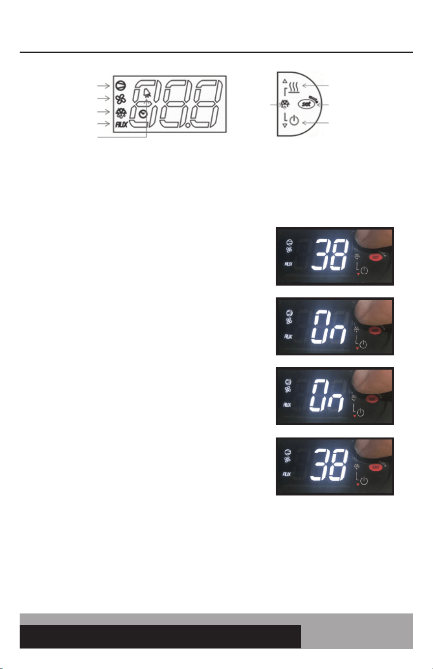
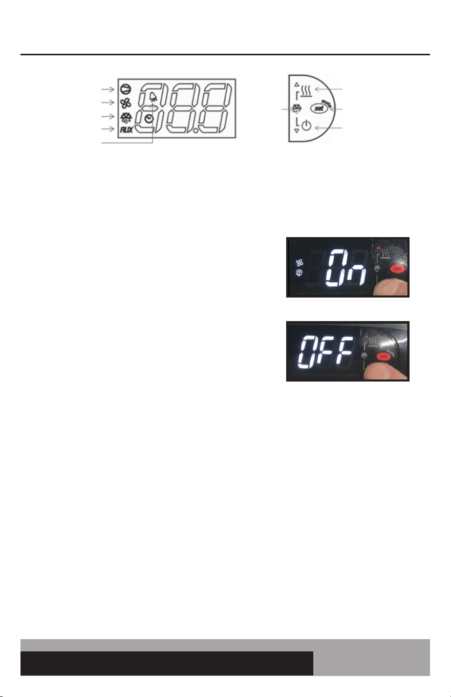
1. To turn OFF controller, press and HOLD the
“POWER/DOWN” button. When “On” appears, hold
the “POWER/DOWN” button for another 5 seconds.
2. To turn controller back ON, press and HOLD the
“POWER/DOWN” button for 5 seconds. Controller
will resume normal operation.
When the control is powered “OFF”, OFF will alternate in the display with the current appliance
temperature.
COMPRESSOR
EVAP FAN
DEFROST
AUX HTRS
ALARM
AUX HTRS (UP)
SET (MUTE)
POWER (DOWN)
DEFROST
2 BUTTONS
14
OPERATIONS MANUAL
HOW TO LOCK/UNLOCK THE CONTROLLER KEYPAD
The controller keypad can be locked to eliminate any unwanted changes to the controller functions.
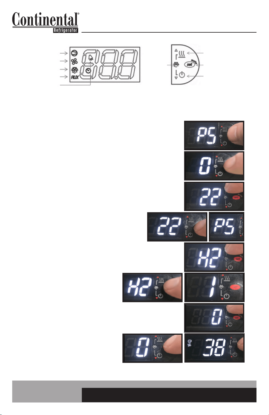
1. Press and HOLD the “SET” button until “PS” appears
flashing in the display. RELEASE the “SET” button.
2. Press and RELEASE the “SET” button. “0” will be in the display.
3. Press the “UP” button until “22” appears. This is the password.
RELEASE the “UP” button.
4. Press and RELEASE the “SET” button. “PS”
will appear in the display.
5. Press the “UP” or “DOWN” button until “H2” appears.
RELEASE the button.
6. Press and RELEASE the “SET” button.
“1” will appear in the display.
7. Press the “UP” or “DOWN” button until “0” appears.
Release the “UP” or “DOWN” button.
8. Press and HOLD the “SET” button
for 5 seconds until the display
returns back to cabinet temperature.
The keypad will now be locked.
To unlock the keypad, follow the same instructions but change H2 from “0” back to “1”.
COMPRESSOR
EVAP FAN
DEFROST
AUX HTRS
ALARM
AUX HTRS (UP)
SET (MUTE)
POWER (DOWN)
DEFROST
2 BUTTONS
15
easy ELECTRONIC CONTROL FOR REFRIGERATORS, FREEZERS AND WARMERS
OPERATIONS MANUAL
HOW TO ACCESS THE TECH SERVICE PARAMETERS
The controller has a tech service level of parameters. Please consult with Continental’s service depart-
ment before accessing these parameters. Adjusting these parameters in the field will affect the appli-
ance’s performance and could void the warranty.
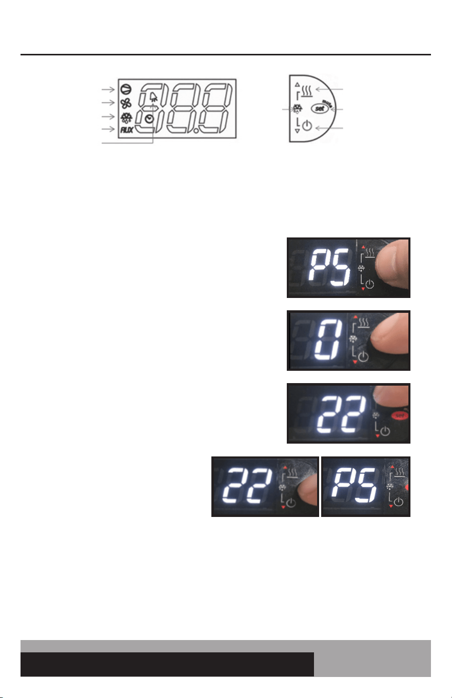
1. Press and HOLD the “SET” button until “PS” appears
flashing in the display. RELEASE the “SET” button.
2. Press and RELEASE the “SET” button. “0”
will be in the display.
3. Press the “UP” button until “22” appears.
This is the password. RELEASE the “UP” button.
4. Press and RELEASE the “SET” button.
“PS” will appear in the display. You
now have access to the tech service
level parameters. Use the “UP” or
“DOWN” button to navigate to the
required parameter.
5. When you get to the parameter you want to change press and RELEASE the “SET” button. The
current setting will be shown in the display. Use the “UP” or “DOWN” button to change the value.
Press and HOLD the “SET” button for 5 seconds to confirm and save the new value. When com-
plete, the current temperature will be displayed. RELEASE the “SET” button.
COMPRESSOR
EVAP FAN
DEFROST
AUX HTRS
ALARM
AUX HTRS (UP)
SET (MUTE)
POWER (DOWN)
DEFROST
2 BUTTONS
16
OPERATIONS MANUAL
HOW TO SEE THE EVAPORATOR PROBE TEMPERATURE
It may be useful for tech service personnel to see the temperature of the evaporator probe.
1. Press and HOLD the “SET” button until “PS” appears flashing
in the display. RELEASE the “SET” button.
2. Press and RELEASE the “SET” button. “0” will be in the display.
3. Press the “UP” button until “22” appears. This is the password.
RELEASE the “UP” button.
4. Press and RELEASE the “SET” button.
“PS” will appear in the display.
5. Press the “UP” or “DOWN” button until “d/” appears.
RELEASE the button.
6. Press and RELEASE the “SET” button. The
evaporator temperature will be in the display.
After 30 seconds, the control will be back to
displaying the cabinet air temperature.
COMPRESSOR
EVAP FAN
DEFROST
AUX HTRS
ALARM
AUX HTRS (UP)
SET (MUTE)
POWER (DOWN)
DEFROST
2 BUTTONS
17
easy ELECTRONIC CONTROL FOR REFRIGERATORS, FREEZERS AND WARMERS
OPERATIONS MANUAL
HOW TO ACTIVATE EZY SET PARAMETERS/RESTORE FACTORY SETTINGS
This is used to activate other preprogrammed parameter settings.
TABLE OF PREPROGRAMMED PARAMETER SETTINGS
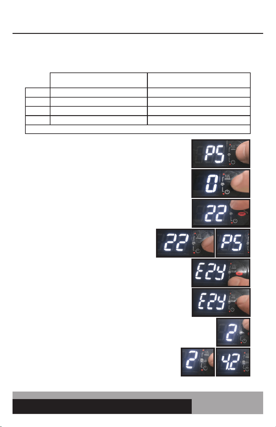
1. Press and HOLD the “SET” button until “PS” appears flashing
in the display. RELEASE the “SET” button.
2. Press and RELEASE the “SET” button. “0” will be in the display.
3. Press the “UP” button until “22” appears. This is the password.
RELEASE the “UP” button.
4. Press and RELEASE the “SET” button.
“PS” will appear in the display.
5. Press and RELEASE the “DOWN” button. “EZY” will appear
in the display.
6. Press and RELEASE the “SET” button. The current EZY set
will appear in the display.
7. Press the “UP” button until EZY SET required is in the display
(see table above). Here “2” was chosen: this is the Celsius
setting for the low and medium temperature controller.
8. Press and HOLD the “SET” button for 5 seconds.
RELEASE the “SET” button. The control will now operate
with the new parameter settings. In this case, the controller
will now operate in degrees Celsius.
NOTE: EZY SET 1 WILL RESTORE THE ORIGINAL FACTORY SETTINGS IN ALL CONTROLLERS.
MEDIUM TEMP: COEA21K
SELF CONTAINED CONTROL
LOW TEMP: C8IA41
SPLIT CONTROL
SET 1 RESTORE FACTORY SETTINGS RESTORE FACTORY SETTINGS
SET 2 3.4°C MEDIUM TEMP FAN PULSING -17.8°C LOW TEMP FAN PULSING
SET 3 55°F WINE REFRIG FAN PULSING -15°F LOW TEMP FAN PULSING
SET 4 38°F FAN CONSTANT 0°F FAN CONSTANT
NOTE: PULSING MEANS FANS ON FOR 1 MIN. AND OFF FOR 3 MIN. THIS CYCLE CONTINUES FOR THE WHOLE OFF CYCLE.
18
OPERATIONS MANUAL
CONTROL TROUBLESHOOTING
Problem Cause Checks
The compressor does
not start (signalled
by the compressor
LED ashing)
1. Compressor safety delay
in progress or defrost post
dripping in progress
1. Wait for compressor safety delays
or defrost dripping time to nish.
Parameters: c0, c1, c2, c3, and dd. The
maximum delay should not exceed 3
minutes.
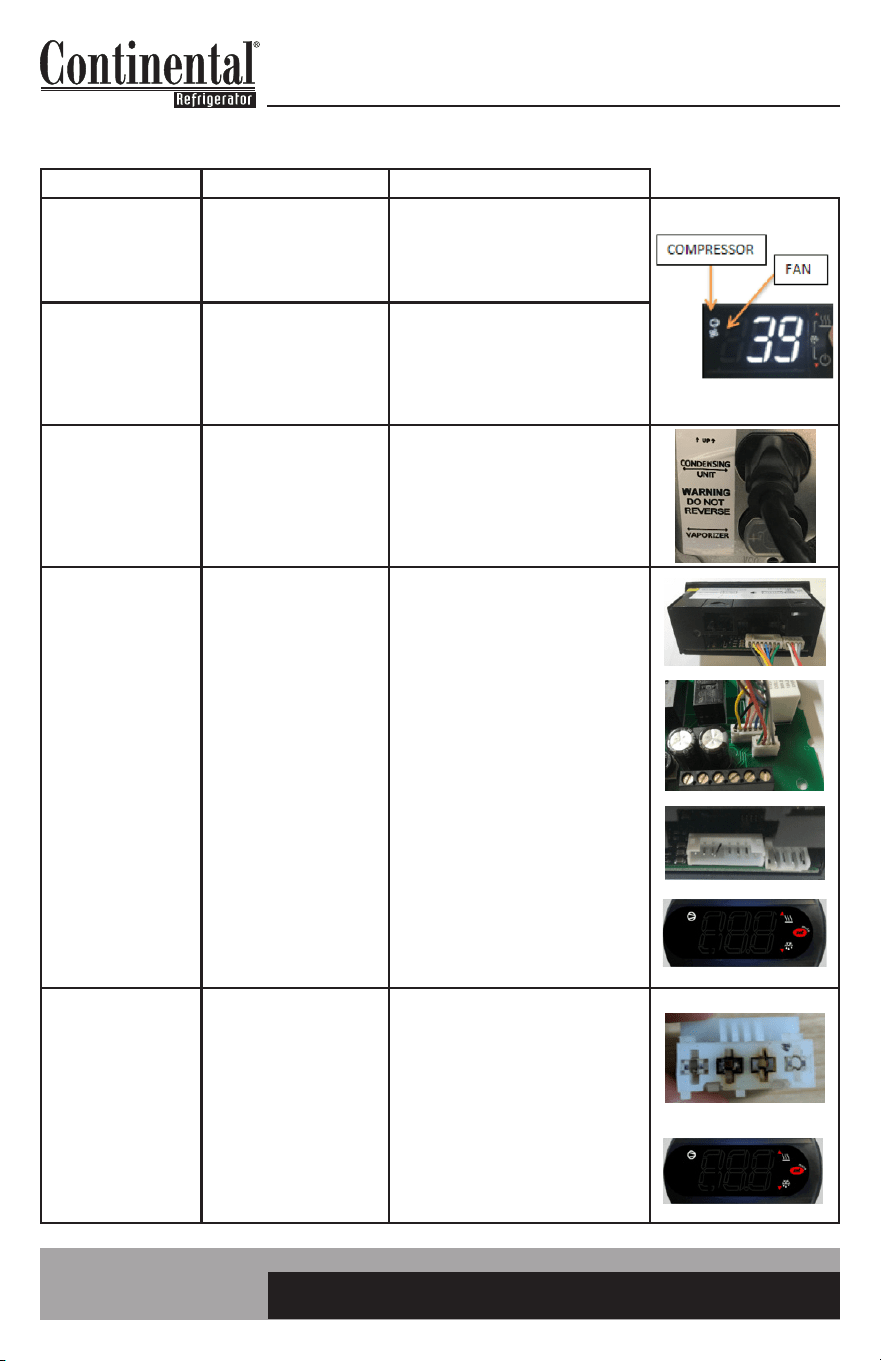
Compressor or Fan
Icon Illuminated
in Display and the
Compressor or Fan is
not Operating
1. Improper wiring
2. Faulty control
1. Check wiring and make sure getting
voltage to the relay.
2. If the dispay icon is iluminated and
getting voltage to the relay but not
across the contacts, the relay is bad.
Condensing
unit running but
compressor icon is
not illuminated on the
display.
1. Condensing unit plugged
into the wrong outlet.
2. Bad compressor relay on
control.
1. Check to make sure condensing
unit plugged into outlet labeled for
condensing unit.
2. If voltage is going across the
compressor relay and the compressor
icon is off, it is a bad relay.
Blank Display Split
Control
1. No power to appliance
or control
2. Connection cable not
fully seated at control
board or display
3. Bent pins where
connection cable attaches
to board or display
4. Moisture damage
5. Firmware error
1. Check power at outlet. Make sure
power switch on control box is ON.
Check power to L & N at control board.
2. Remove display and check to make
sure white connectors are fully seated
and correct orientation. Check display
cable at control board to make sure
white connectors are fully seated and
correct orientation.
3. Remove display cable at display and
board and check to make sure pins are
not bent.
4. Check for signs of moisture damage
at or behind the control board. Remove
the display and check for signs of
moisture damage on the display board
5. Check to see if display is blank
except for compressor icon.
Blank Display Self
Contained Control
1. No power to appliance
or control
2. Moisture damage
3. Firmware error
1. Check power at outlet. Make sure
power switch on control box is ON.
Check power to terminals 6 & 7 at
control. Check terminal(s) that plug
into control and look for burn marks or
loose connections.
2. Check for signs of moisture damage
on the board of the control.
3. Check to see if display is blank
except for compressor icon.
19
easy ELECTRONIC CONTROL FOR REFRIGERATORS, FREEZERS AND WARMERS
OPERATIONS MANUAL
CONTROL TROUBLESHOOTING (Continued)
Problem Cause Checks
Error Codes:
E0 - Regulation Probe
Error (Black)
E1 - Evaporator Probe
Error (Red)
E2 - Ambient Probe
Error (White)
1. Loose probe wire/
connections
2. Bad probe
3. Bad control
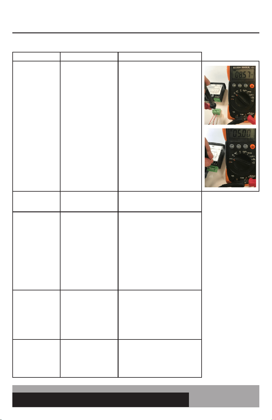
1. Make sure probes are installed in
proper terminals. See parameter section
of manual for wiring locations. Make
sure the green terminal block on the self-
contained control is fully seated. Make
sure there are not any loose strands of
wire. Make sure screw terminals are
not clamping down on wire sheathing
instead of the probe wire.
2. Ohm out probe. See Probe Resistance
Value Chart. For self contained control
can remove the green terminal block of
probe wires from control and then take
resistance values on the screw terminals.
For split control, must remove probe to
take resistance.
3. Remove probes from the control.
With control powered, should get 5VDC
between probe common and other
terminal probe screws into.
Error Codes:
L0 - Low Temperature
HI - High Temperature
1. Cabinet temperature
exceeds alarm set point for
60 minutes.
1. Check alarm parameters: AL, AH, Ad.
Display High
Temperature
1. Something wrong with
refrigeration system.
2. Door was just opened
for a long duration,
excessive door openings,
loading warm product,
missing pans in rail.
3. Set point too high
1. Do standard refrigeration system
checks.
2. Keep door closed and see if tempera-
ture pulls down. NOTE: Display reads
cabinet air, not product temperature.
3. Check set point and adjust if
necessary. Can also increase the display
delay parameters to slow down display
response. Increase the /3 parameter on
the split by 1. Increase the /2 parameter
on the self contained by 5.
Evaporator Coil Icing
1. Something wrong with
refrigeration system.
2. Insufcient defrost time
3. Parameters incorrect
1. Do standard refrigeration system
checks.
2. Check the DI and Dt parameters.
Adjust if necessary.
3. Check parameters to parameter list in
this manual.
After modifying a
parameter, controller
continues working
with old values
1. The control has not
updated the old value
or the parameter setting
procedure has not been
ended correctly by pressing
the SET button for 3 s
1. Temporarily disconnect and reconnect
power to the control. Go back in to
parameter to see if the change worked.
20
OPERATIONS MANUAL
ELECTRONIC CONTROL ERROR CODES
Alarm Code Alarm Description Notes
E0 Regulation Probe Error Located in return air stream (black)
E1 Evaporator Prope Error Located in evaporator coil (red)
E2 Ambient Probe Error Located by condensing unit (white)
LO Low Temperature Alarm Reference “AL” & “Ad” alarm parameter
HI High Temperature Alarm Reference “AH” & “Ad” alarm parameter
Note: If there is a probe error, first check connection to electronic control. Then check resistance value. See troubleshooting section of
manual.
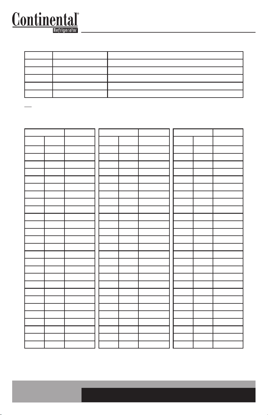
PROBE RESISTANCE VALUES
Temp. Resistance Temp. Resistance Temp. Resistance
°F °C Typ KΩ °F °C Typ KΩ °F °C Typ KΩ
-15 -26 90.84 34 1 26.13 82 28 8.94
-13 -25 86.43 36 2 25.03 84 29 8.62
-11 -24 82.26 37 3 23.99 86 30 8.31
-9 -23 78.33 39 4 23.00 88 31 8.01
-8 -22 74.61 41 5 22.05 90 32 7.73
-6 -21 71.10 43 6 21.15 91 33 7.45
-4 -20 67.77 45 7 20.30 93 34 7.19
-2 -19 64.57 46 8 19.48 95 35 6.94
0 -18 61.54 48 9 18.70 97 36 6.70
1 -17 58.68 50 10 17.96 99 37 6.47
3 -16 55.97 52 11 17.24 100 38 6.28
5 -15 53.41 54 12 16.56 102 39 6.03
7 -14 50.98 55 13 15.90 104 40 5.83
9 -13 48.68 57 14 15.28 106 41 5.63
10 -12 46.50 59 15 14.69 108 42 5.44
12 -11 44.43 61 16 14.12 109 43 5.26
14 -10 42.47 63 17 13.58 111 44 5.08
16 -9 40.57 64 18 13.06 113 45 4.91
18 -8 38.77 66 19 12.56 115 46 4.75
19 -7 37.06 68 20 12.09 117 47 4.59
21 -6 35.44 70 21 11.63 118 48 4.44
23 -5 33.90 72 22 11.20 120 49 4.30
25 -4 32.44 73 23 10.78 122 50 4.16
27 -3 31.05 75 24 10.38 124 51 4.03
28 -2 29.73 77 25 10.00 126 52 3.90
30 -1 28.48 79 26 9.63 157 53 3.77
32 0 27.28 81 27 9.28 129 54 3.65
21
easy ELECTRONIC CONTROL FOR REFRIGERATORS, FREEZERS AND WARMERS
OPERATIONS MANUAL
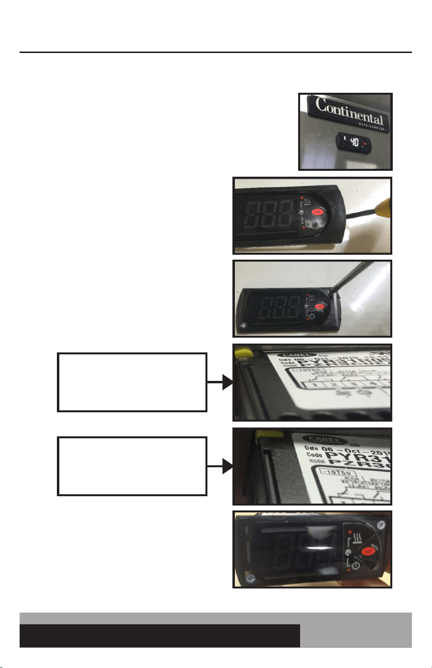
HOW TO REMOVE THE ELECTRONIC CONTROL
1. Turn off power to the unit.
2. Place tip of small flat head screw driver under
plastic bezel and gently pry up on bezel to
remove.
3. Use a PZ1 screw driver (#1 Phillips will also
work) and turn both screws ¼ turn counter
clockwise. This will rotate the plastic keeper
behind the sheet metal to be able to pull out
the electronic control.
4. To re-install the control, push the control
back into the rectangular cutout. Turn the
(2) screws clockwise to rotate the keeper
back in place and secure the control. Snap
back on the plastic bezel.
Plastic Keeper. When turning screw
counter clockwise, this will rotate
this keeper.
When the screw is turned ¼ turn
CCW, the plastic keeper will be in a
position to remove the control.
22
OPERATIONS MANUAL
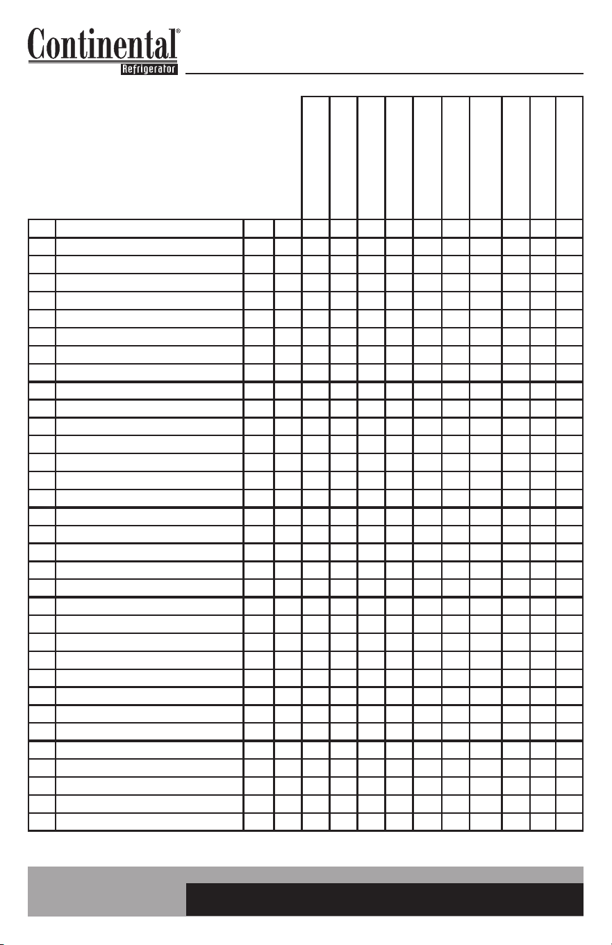
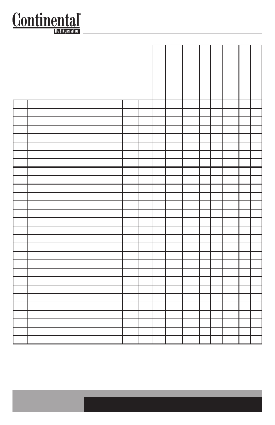
SPLIT CONTROL PARAMETERS
Par. Description Level Unit Set Set Set Set Set Set Set Set Set Set
/2 measurement stability: lower quicker resp PW - 4 4 4 4 4 4 4 4 4 4
/3 probe display response: lower quicker resp PW - 1 1 1 1 1 1 1 1 1 1
/4 probe display select 1: box 2: evap 3: amb PW - 1 1 1 1 1 1 1 1 1 1
/5 units in °C (0) or °F (1) PW - 1 1 1 1 0 1 1 1 1 1
/6 decimal display (0) or not (1) PW - 1 1 1 1 0 1 1 1 1 1
/C1 probe 1 offset (display) User °F 2.5 2.5 2.5 1.2 1.4 1.2 0 1.2 2.5 10.0
/C2 probe 2 offset (evap) PW °F 1 1 1 1 0.6 1.2 0 1 1 1
/C3 probe 3 offset (ambient) PW °F 0 0 0 0 0 0 0 0 0 0
St set point (cutout) User °F -2 -10 -15 26 -18.9 36 36 26 -3 -2
rd differential (positive dif) PW °F 5 5 5 4 2.8 4 3 4 6 5
r1 minimum set point allowed PW °F -10 -18 -18 20 -23.3 32 32 20 -10 -10
r2 maximum set point allowed PW °F 15 15 15 40 -9.4 40 40 40 15 15
FH FH enabled PW - 1 1 1 1 1 2 2 2 1 1
FHt fascia heater threshold: temp heaters turn on PW °F 80 80 80 80 26.7 80 80 80 80 80
FHd fascia heater differential PW °F 1 1 1 1 1 1 1 1 1 1
c0 comp and fan start delay power up PW min 1 1 1 1 1 1 1 1 1 1
c1 min time between starts PW min 2 2 2 2 2 3 3 2 2 2
c2 min comp off time PW min 1 1 1 1 1 1 1 1 1 1
c3 min comp on time PW min 1 1 1 1 1 2 2 1 1 1
c4 compressor on time with duty cycle PW min 14 15 15 8 14 6 6 8 14 14
d0 type of defrost PW - 0 0 0 0 0 0 0 0 0 0
dl interval between defrosts User hr 6 8 8 8 8 6 6 8 8 8
dt end defrost temperature PW °F 50 50 50 44 10 40 44 44 50 50
dP max defrost duration PW min 30 30 30 20 30 40 40 20 30 30
d6 display during defrost (1: temp 2: DF) PW - 1 1 1 1 1 1 1 1 1 1
dd dripping time PW min 3 3 3 3 3 0 0 3 3 3
d8 alarm bypass after defrost PW hr 2 2 2 2 2 2 2 2 2 2
d/ display defrost probe (displays def temp) PW °F - - - - - - - - - -
A0 alarm and fan differential PW °F -10 -10 -10 -10 -5.6 -2 -2 -10 -10 -10
AL low temp alarm F °F -20 -20 -25 15 -28.9 30 30 15 -20 -20
AH high temp alarm F °F 40 40 40 50 4.4 50 50 50 40 40
Ad temp alarm delay PW min 60 60 60 60 60 60 60 60 60 60
A4 third input config (0: not used 13: amb probe) PW - 13 13 13 13 13 0 0 0 13 13
C8IA41
UPRIGHT FRZR, SWF
1.215/.216
REV. 5/21/2019
C8IA41>-10D
UPRIGHT FRZR -10F
C8IA41>-15D
UPRIGHT FRZR -15F
C8IA41>28D
UPRIGHT FRZR 28F
C8IA41>CEL
UPRIGHT FRZR CELSIUS
C8IA41>38D
SW SOLID TOPS
C8IA41>38DOT
SW OPEN TOPS
C8IA41>28DNH
SW SOLID TOP 28F
C8IA41>EFC
1FS, 1FSE, DL1FS, DL1FSE
C8IA41>CFA
CFA MODELS
23
easy ELECTRONIC CONTROL FOR REFRIGERATORS, FREEZERS AND WARMERS
OPERATIONS MANUAL
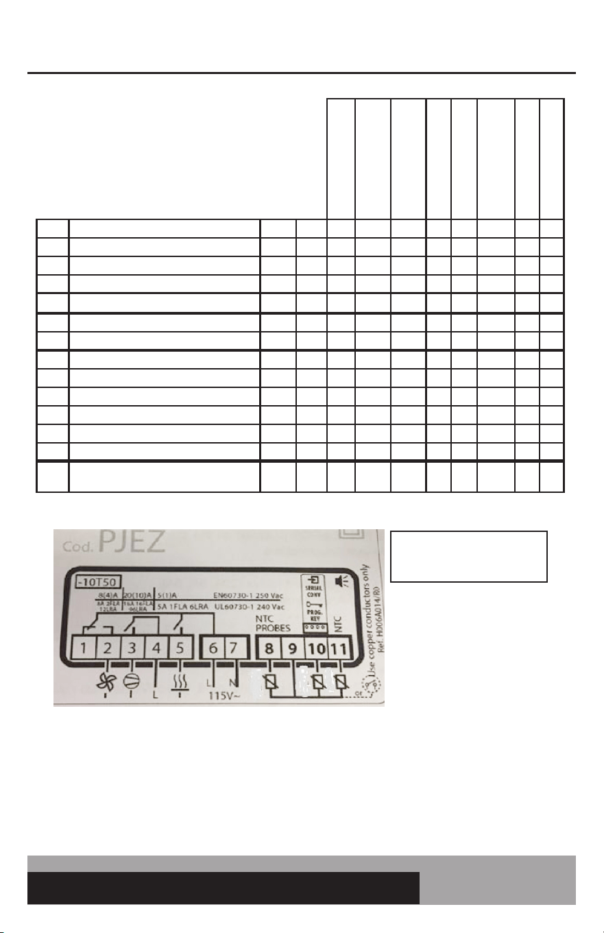
Par. Description Level Unit Set Set Set Set Set Set Set Set Set Set Set
F0
evap fan operation
(0: on, 1: based on set pt. see F1)
PW - 1 1 1 1 1 0 0 1 1 1 0
F1 evap fan control set point PW °F 30 30 30 42 -1.1 40 40 42 20 30 40
F2
stop evap fans if comp stops (0: per F0
1: off w/comp 2: cyclical see F4 & F5
PW - 2 2 2 2 2 2 0 2 1 2 2
F3
evap fan status during defrost
(0: on 1: off)
PW - 1 1 1 1 1 0 0 1 1 1 0
Fd post-dripping time PW min 0 0 0 0 0 0 0 0 0 0 0
F4 fan duty on time (when F2=2) PW min 1 1 1 1 1 1 100 1 1 1 1
F5 fan duty off time (when F2=2) PW min 3 3 3 3 3 3 0 3 3 3 3
Pw password User - 22 22 22 22 22 22 22 22 22 22 22
H0
serial address (if connecting to
monitoring)
PW - 1 1 1 1 1 1 1 1 1 1 1
H1
AUX output config (0: inactive 8: fac
htr)
PW - 8 8 8 8 8 0 0 0 8 8 0
H2 key enabled PW - 1 1 1 1 1 1 1 1 1 1 1
H4 disable buzzer User - 0 0 0 0 0 0 0 0 0 0 0
H5 detect changed parameters PW - 0 0 0 0 0 0 0 0 0 0 0
H7 management of 4th relay/serial comm PW - 1 1 1 1 1 1 1 1 1 1 1
H99 parameter level PW - 66 51 52 53 54 56 63 55 58 62 59
EZY
EZY sets (1: reset 2: Celsius 3: -15F
4: fan constant
PW - 0 0 0 0 0 0 0 0 0 0 0
If control number not listed here, please
consult factory. Celsius Temps in °C.
C8IA41
UPRIGHT FRZR, SWF
C8IA41>-10D
UPRIGHT FRZR -10F
C8IA41>-15D
UPRIGHT FRZR -15F
C8IA41>28D
UPRIGHT FRZR 28F
C8IA41>CEL
UPRIGHT FRZR CELSIUS
C8IA41>38D
SW SOLID TOPS
C8IA41>38DOT
SW OPEN TOPS
C8IA41>28DNH
SW SOLID TOP 28F
C8IA41>EFC
1FS, 1FSE, DL1FS, DL1FSE
C8IA41>CFA
CFA MODELS
C8IA41>48D
SW SOLID TOP 48F
Use copper conductors only
Power Supply
115/230/Vac
(depending on the model)
24A max (*)
Display
Interface
SERIAL
CONV
PROG
KEY
up to 5m
REGULATION PROBE: BLACK
DEFROST PROBE: RED
AMBIENT PROBE: WHITE
Ambient probe not installed on:
*C8IA41>38DNH
*C8IA41>38DOT
24
OPERATIONS MANUAL
Par. Description Level Unit Set Set Set Set Set Set Set Set
/2 measurement stability: lower quicker response PW - 4 5 4 4 4 4 2 4
/4 probe display selection 1: box 2: evap 3: amb PW - 1 1 1 1 1 1 1 1
/5 units in °C (0) or °F (1) PW - 1 1 1 1 1 0 1 1
/6 decimal display (0) or not (1) PW - 1 1 1 1 1 0 1 1
/C1 probe 1 offset (display) User °F 1.2 1.2 1.2 1.2 1.0 0.7 1.0 1.2
/C2 probe 2 offset (evap) PW °F 1.2 1.2 1.2 1.2 1.0 0.7 0.0 1.2
/C3 probe 3 offset (ambient) PW °F 0 0 0 0 0 0 0 0
St set point (cutout) User °F 36 36 36 25 51 2.2 38 35
rd differential (positive dif) PW °F 4 3 3 5.0 4 2.2 3 5
r1 minimum set point allowed PW °F 32 32 33 20 34 0 32 33
r2 maximum set point allowed PW °F 40 40 40 38 55 4.4 40 40
FH FH enabled PW - 1 2 2 2 1 1 2 2
FHt fascia heater threshold: 0 inactive PW °F 80 0 0 0 80 26.7 0 0
FHd fascia heater differential PW °F 1 1 1 1 1 1 1 1
Pr power User - 1 1 1 1 1 1 1 1
c0 comp and fan start delay power up PW min 1 1 1 1 1 1 1 1
c1 min time between starts PW min 3 2 2 3 3 3 3 2
c2 min comp off time PW min 1 1 1 1 1 1 1 1
c3 min comp on time PW min 2 1 1 2 2 2 2 1
c4 compressor on time with duty cycle PW min 6 6 6 8 5 6 3 6
d0 type of defrost: 1 time init., time or temp term. PW - 1 1 1 1 1 1 0 1
dl interval between defrosts User hr 6 6 6 8 6 6 0 6
dt end defrost temperature PW °F 44 44 45 50 44 6.7 37 45
dP max defrost duration PW min 40 40 40 30 40 40 60 40
d6 display during defrost (1: temp 2: DF) PW - 1 1 1 1 1 1 0 1
dd dripping time PW min 0 0 0 3 0 0 0 0
d8 alarm bypass after defrost PW hr 2 2 2 2 2 2 2 2
d/ display defrost probe (displays def temp) PW °F - - - - - - - -
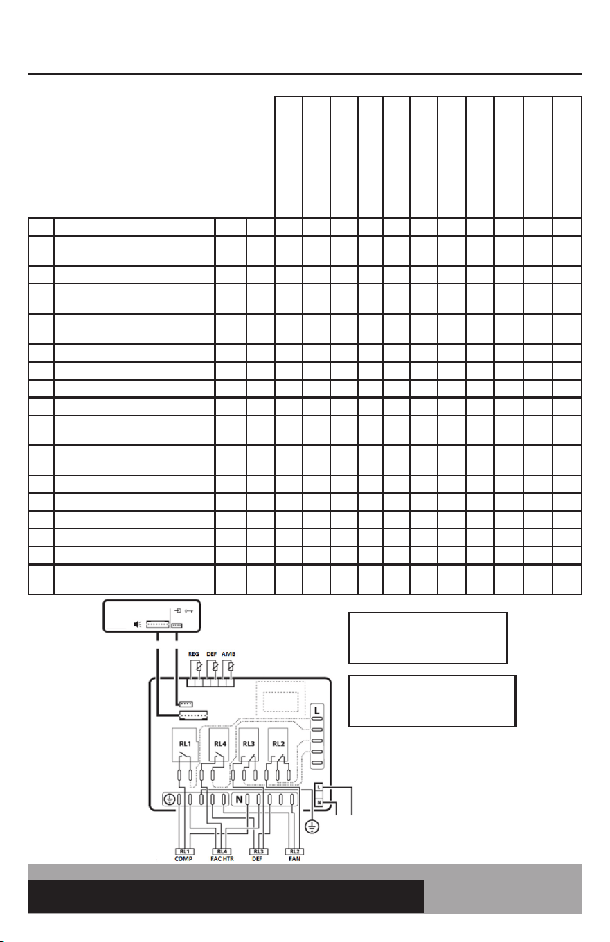
SELF-CONTAINED CONTROL PARAMETERS
2.015/.016 PARAMETERS
Rev. 10/29/2019
C0EA21K
LINE1 UPRIGHT REF
C0EA21K>NH
CRA SOLID TOP, BBC, KC,
CBC
C0EA21K>38DOT
CRA OPEN TOP, CPA,
GRIDDLE REF
C0EA21K>32DNH
BBC DEEP CHILL
C0EA21K>55D
LINE 1 UPRIGHT 55 DEG
C0EA21K>CEL
LINE 1 UPRIGHT REF
CELSIUS
C0EA21K>MCCW
MILK COOLER COLD WALL
C0EA21K>MC
MILK COOLER AIR
25
easy ELECTRONIC CONTROL FOR REFRIGERATORS, FREEZERS AND WARMERS
OPERATIONS MANUAL
If control number not listed here, please consult factory.
Celsius Temps in °C.
C0EA21K: RELAY 5 FOR FASCIA HEATERS
C0EA21K>NH: RELAY 5 NOT USED. AMBIENT (WHITE) PROBE NOT USED
C0EA21K>38DOT: RELAY 5 NOT USED. AMBIENT (WHITE) PROBE NOT USED
C0EA21K>32DNH: RELAY 5 FOR DEF HEATER. AMBIENT (WHITE) PROBE NOT USED
C0EA21K>CEL: RELAY 5 FOR FASCIA HEATERS
C0EA21K>MCCW: RELAY 5 NOT USED. RELAY 2 NOT USED. AMBIENT (WHITE) NOT USED. DEF (RED) NOT USED.
COEA21K>MC: RELAY 5 NOT USED. AMBIENT (WHITE) NOT USED.
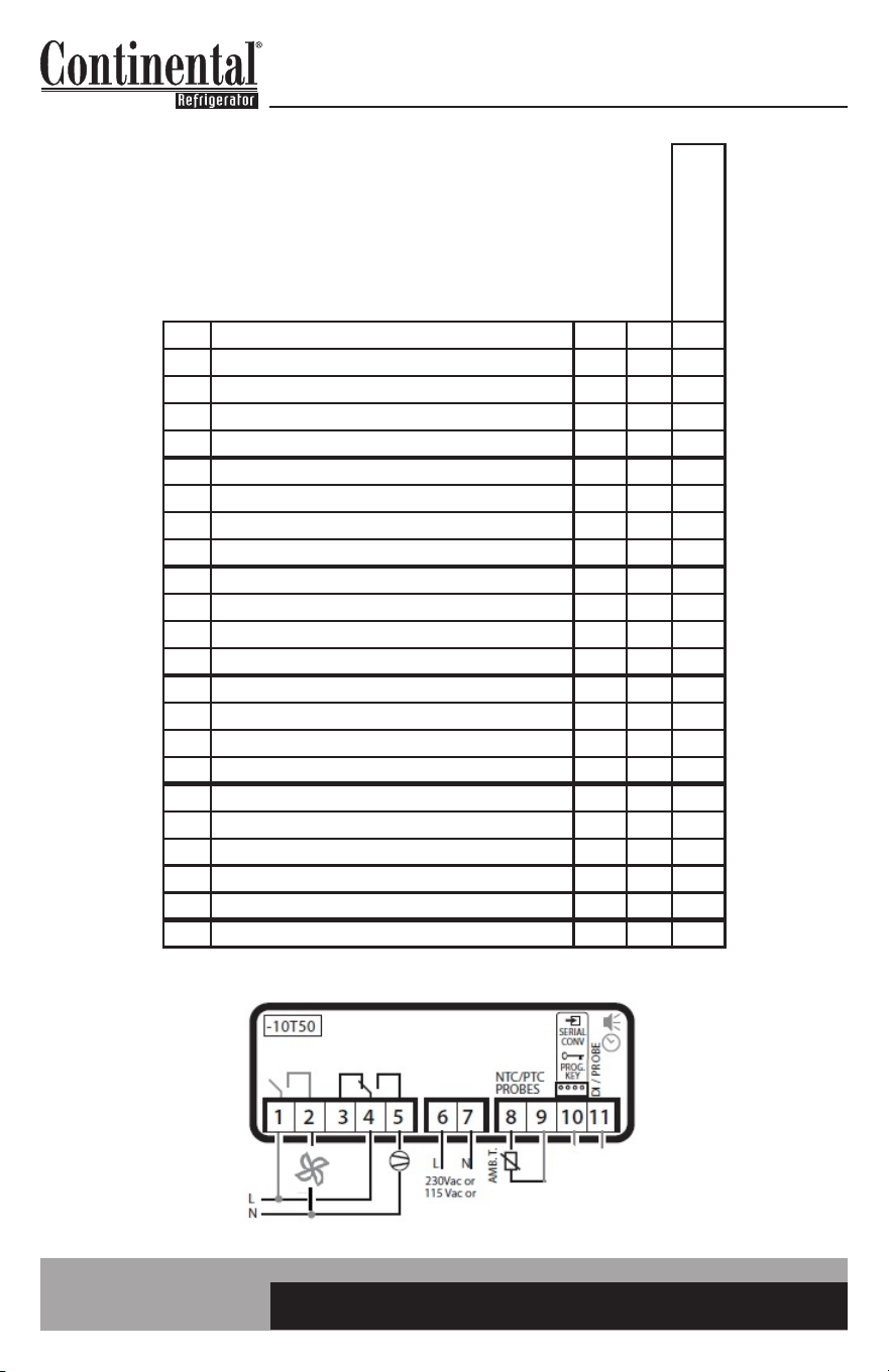
REGULATION PROBE: BLACK
DEFROST PROBE: RED
AMBIENT PROBE: WHITE
REG DEF AMB
Par. Description Level Unit Set Set Set Set Set Set Set Set
A0 alarm and fan temp differential PW °F -2 -2 -2 -5 -2 -1.2 -2 -2
AL low temp alarm F °F 30 30 25 18 30 -1.1 30 25
AH high temp alarm F °F 50 50 50 50 65 10 50 50
Ad temp alarm delay PW min 60 60 60 60 60 60 60 60
Fd0 fan duty on time PW min 1 1 100 100 1 1 0 100
FdF fan duty off time PW min 3 3 0 0 3 3 3 0
Pw password User - 22 22 22 22 22 22 22 22
H0 serial address (if connecting to monitoring) PW - 1 1 1 1 1 1 1 1
H2 key enabled PW - 1 1 1 1 1 1 1 1
H4 disable buzzer User - 0 0 0 0 0 0 0 0
H5 detect changed parameters PW - 0 0 0 0 0 0 0 0
H99 parameter level PW - 0 10 11 3 5 4 6 13
EZY
EZY sets (1: reset 2: Celsius 3: wine
4: fan constant
PW - 0 0 0 0 0 0 0 0
C0EA21K
LINE1 UPRIGHT REF
C0EA21K>NH
CRA SOLID TOP, BBC, KC,
CBC
C0EA21K>38DOT
CRA OPEN TOP, CPA,
GRIDDLE REF
C0EA21K>32DNH
BBC DEEP CHILL
C0EA21K>55D
LINE 1 UPRIGHT 55 DEG
C0EA21K>CEL
LINE 1 UPRIGHT REF
CELSIUS
C0EA21K>MCCW
MILK COOLER COLD WALL
C0EA21K>MC
MILK COOLER AIR
26
OPERATIONS MANUAL
WARMER CONTROL PARAMETERS
If control number is not listed here,
please consult factory.
Par. Description Level Unit Set
/2 Measurement Stability: Lower quicker response PW - 2
/5 Units in °C (0) or °F (1) PW - 1
/6 decimal display (0) or not (1) PW - 1
/C1 probe 1 offset (display) User °F 4.0
St set point (cutout) User °F 182
rd differential (negative dif) PW °F 2
r1 minimum set point allowed PW °F 90
r2 maximum set point allowed PW °F 195
c1 min time between starts PW min 0
c2 min heater off time PW min 0
c3 min heater on time PW min 0
c4 heater on time with duty cycle PW min 9
A0 alarm and fan temp differential PW °F -2
AL low temp alarm F °F 60
AH high temp alarm F °F 220
Ad temp alarm delay PW min 60
Pw password User - 22
H0 serial address (if connecting to monitoring) PW - 1
H2 keypad enabled PW - 1
H4 disable buzzer User - 0
H5 detect changed parameters PW - 1
EZY EZY Sets (1: Reset, 2: Celsius) PW - 0
S2L000>W (220V)
S2L100>W (115V)
WARMER


IM-EC-50154-20191120
A Division of National Refrigeration & Air Conditioning Products, Inc.
539 Dunksferry Road • Bensalem, PA 19020-5908
Phone: 215-244-1400 • Toll Free: 800-523-7138
www.continentalrefrigerator.com