
© 2025 GeoVision, Inc. All rights reserved.
Under the copyright laws, this manual may not be copied, in whole or in part,
without the written consent of GeoVision.
Every effort has been made to ensure that the information in this manual is
accurate. GeoVision, Inc. makes no expressed or implied warranty of any kind
and assumes no responsibility for errors or omissions. No liability is assumed
for incidental or consequential damages arising from the use of the information
or products contained herein. Features and specifications are subject to
change without notice.
GeoVision, Inc.
9F, No. 246, Sec. 1, Neihu Rd.,
Neihu District, Taipei, Taiwan
Tel: +886-2-8797-8377
Fax: +886-2-8797-8335
http://www.geovision.com.tw
Trademarks used in this manual: GeoVision, the GeoVision logo and GV
series products are trademarks of GeoVision, Inc. Windows is the registered
trademark of Microsoft Corporation.
April 2025
Scan the following QR codes for product warranty and technical support
policy:
[Warranty] [Technical Support Policy]

1
Contents
Overview ....................................................................................................................... 5
1. Read Before Use ......................................................................................... 5
2. Regulatory Information ............................................................................... 5
1 Connect the Camera ........................................................................................... 6
1. Note ............................................................................................................... 6
2. Single Camera ............................................................................................. 7
3. Multiple Cameras ........................................................................................ 7
2 Web Interface ........................................................................................................ 8
1. Log In ............................................................................................................ 8
2. Transport Layer Security .......................................................................... 10
3. User Permissions for Web/HTTPS ......................................................... 10
4. Auto Logout ................................................................................................ 11
5. Auto play Policy ......................................................................................... 12
3 Live View ............................................................................................................. 12
1. Overview ..................................................................................................... 12
2. Microphone ................................................................................................. 12
3. Volume ........................................................................................................ 13
4. Snapshot ..................................................................................................... 13
5. Full Screen ................................................................................................. 13
6. Zoom In & Zoom Out ................................................................................ 14
7. Focus ........................................................................................................... 14
8. Refresh Focus............................................................................................ 14
4 Image & Image Parameters ............................................................................. 15
1. Image Adjustment ..................................................................................... 15
2. White Balance ............................................................................................ 15
5 Image & Image Configs ..................................................................................... 16
6 Image & Exposure Mode .................................................................................. 16
1. Create a BLC Rectangle .......................................................................... 16
7 Image & Advanced Setting ............................................................................... 17
1. Components ............................................................................................... 18
2. IR-Cut Filter Removal (ICR) .................................................................... 18
3. Exposure ..................................................................................................... 18
4. Levels .......................................................................................................... 18
5. Navigator Viewer ....................................................................................... 18

2
6. Focus ........................................................................................................... 19
7. Save & Reset ............................................................................................. 19
8. Duplicate ..................................................................................................... 19
8 Image & Schedule .............................................................................................. 20
1. Overview ..................................................................................................... 20
2. Camera Date & Time ................................................................................ 20
3. Year/Season Switch Control .................................................................... 20
4. Year Mode .................................................................................................. 20
5. Season Mode ............................................................................................. 21
9 System & Device ................................................................................................ 22
1. Camera Name............................................................................................ 22
2. Date And Time ........................................................................................... 22
3. Time Picker ................................................................................................. 22
10 System & Stream Configs .................................................................................. 23
1. Web Stream ............................................................................................... 23
2. Main Camera Stream................................................................................ 23
3. Second Camera Stream ........................................................................... 23
11 System & Privacy Mask ...................................................................................... 24
1. Mask Status................................................................................................ 24
2. The Mask Rule ........................................................................................... 24
3. Priority of Overlay & Mask ....................................................................... 25
12 Overlay .................................................................................................................. 26
1. Stamp .......................................................................................................... 26
2. Overlay Preview ........................................................................................ 26
3. Basic Setting .............................................................................................. 26
4. Add Photo ................................................................................................... 27
5. Position ....................................................................................................... 27
13 System & Audio .................................................................................................... 27
1. Microphone ................................................................................................. 27
2. Speaker ....................................................................................................... 28
3. Synchronized with The Live View ........................................................... 28
14 System & Digital I/O ............................................................................................ 28
1. Digital Input ................................................................................................ 28
2. Digital Output ............................................................................................. 29
15 System & License Plate Recognition ............................................................... 30
1. Recognition Result .................................................................................... 30
2. LPR Detection ............................................................................................ 31
3. RS-485 ........................................................................................................ 34

3
4. Inquire Recognized Databse ................................................................... 35
5. Registry Database ..................................................................................... 36
6. Push Notification........................................................................................ 38
7. Recongizing Schedule .............................................................................. 38
8. Storage........................................................................................................ 39
9. License ........................................................................................................ 40
16 Network Basic ...................................................................................................... 40
1. Different Display Types............................................................................. 40
2. Change Network Type .............................................................................. 40
17 Network Advanced ............................................................................................... 41
1. Device Discovery ....................................................................................... 41
18 Network IEEE 802.1X ......................................................................................... 41
1. Upload a File .............................................................................................. 41
2. Switch To EAP-TLS ................................................................................... 41
3. Switch To EAP-TTLS / PEAP .................................................................. 42
4. Refresh........................................................................................................ 42
19 Notification – Camera Log .................................................................................. 43
1. Setting (Default) ......................................................................................... 43
2. Log List........................................................................................................ 43
3. Export .......................................................................................................... 43
20 Notification – Event Setting ................................................................................ 44
1. Add New Event .......................................................................................... 44
2. Event List .................................................................................................... 44
3. Edit Event ................................................................................................... 45
4. Delete the Event ........................................................................................ 45
21 Notification - Trigger Source .............................................................................. 46
22 Notification - Notify Setting ................................................................................. 46
1. Notify Method ............................................................................................. 46
23 Storage .................................................................................................................. 47
1. SD Card ...................................................................................................... 47
24 Administration ....................................................................................................... 49
1. Firmware Update ....................................................................................... 49
2. Backup & Restore ..................................................................................... 49
3. Reboot ......................................................................................................... 49
4. Factory Reset ............................................................................................. 49
5. SSH Server ................................................................................................ 50
6. Public Key File ........................................................................................... 50
25 Password .............................................................................................................. 51

4
1. Change Password ..................................................................................... 51
2. Password Not Match ................................................................................. 52
26 Language .............................................................................................................. 52
27 Log Out .................................................................................................................. 52

5
Overview
1. Read Before Use
⚫ The Manual includes instructions for using and managing the Product.
Pictures, charts, images and all other information hereinafter are for
description and explanation only. The information contained in the Manual is
subject to change, without notice, due to firmware updates or other reasons.
Please find the latest version of this Manual at GeoVision’s website
(https://www.geovision.com.tw/download/product/).
⚫ The Network Camera is a network device and its use should be
straightforward for those who have basic networking knowledge. It is
designed for various applications including video sharing, general
security/surveillance, etc. The use of surveillance devices may be prohibited
by law in your country. The Network Camera is not only a high-performance
web-ready camera but can also be part of a flexible surveillance system. It is
the user’s responsibility to ensure that the operation of such devices is legal
before installing this unit for its intended use.
2. Regulatory Information
⚫ FCC Information
This equipment has been tested and found to comply with the limits for a Class A
digital device, pursuant to part 15 of the FCC rules.
This device compiles with FCC Rules Part 15. Operation is subject to the following
two conditions.
➢ This device may not cause harmful interference, and
➢ This device must accept any interference received, including interference
that may cause undesired operation.
These limits are designed to provide reasonable protection against harmful
interference when the equipment is operated in a commercial environment. This
equipment generates, uses, and can radiate radio frequency energy and, if not
installed and used in accordance with the instruction manual, may cause harmful
interference to radio communications. Operation of this equipment in a residential
area is likely to cause harmful interference in which case the user will be required to
correct the interference at his own expense.
⚫ EU Conformity Statement
This product and - if applicable - the supplied accessories too are marked with "CE"

6
and comply therefore with the applicable harmonized European standards listed
under the the EMC Directive 2014/30/EU, the RoHS Directive 2011/65/EU.
2012/19/EU (WEEE directive): Products marked with this symbol cannot be
disposed of as unsorted municipal waste in the European Union. For proper
recycling, return this product to your local supplier upon the purchase of equivalent
new equipment, or dispose of it at designated collection points. For more
information see: www. recyclethis.info
⚫ Safety
Power Supply : The input voltage should conform to IEC60950-1 standard: SELV
(Safety Extra Low Voltage) and the LPS (Limited Power Source). Refer to the
appropriate documentation for detailed information. DO NOT connect multiple
devices to one power adapter, to avoid over-heating or fire hazards caused by
overload. Make sure the plug is properly connected to the power socket.
When used with Power over Ethernet (PoE), the Power Sourcing Equipment PSE)
shall comply with IEEE 802.3af and Limited Power Source (LPS) according to
clause 2.5 of IEC/EN/UL 60950-1 or annex Q of IEC/EN/UL 62368-1.
1 Connect the Camera
1. Note
⚫ Make sure the device in the package is in good condition and all the
assembly parts are included.
⚫ Please refer to Quick Start Guide for camera installation.
7
2. Single Camera
⚫ The IP segments, Subnet mask and default gateway must be same for both IP
camera and computer. Ensuring IP camera and computer are on the same
router.
⚫ Enable DHCP in router. Accessing via web browser then login with default
account information (user name: admin, password: admin). DHCP is the
default network setting of camera.
⚫ If routers fails to assign IP address by DHCP, the network setting will change
to static IPv4 IP address (default: https://192.168.0.10), find the camera and
login the web browser with default account information and connect Camera.
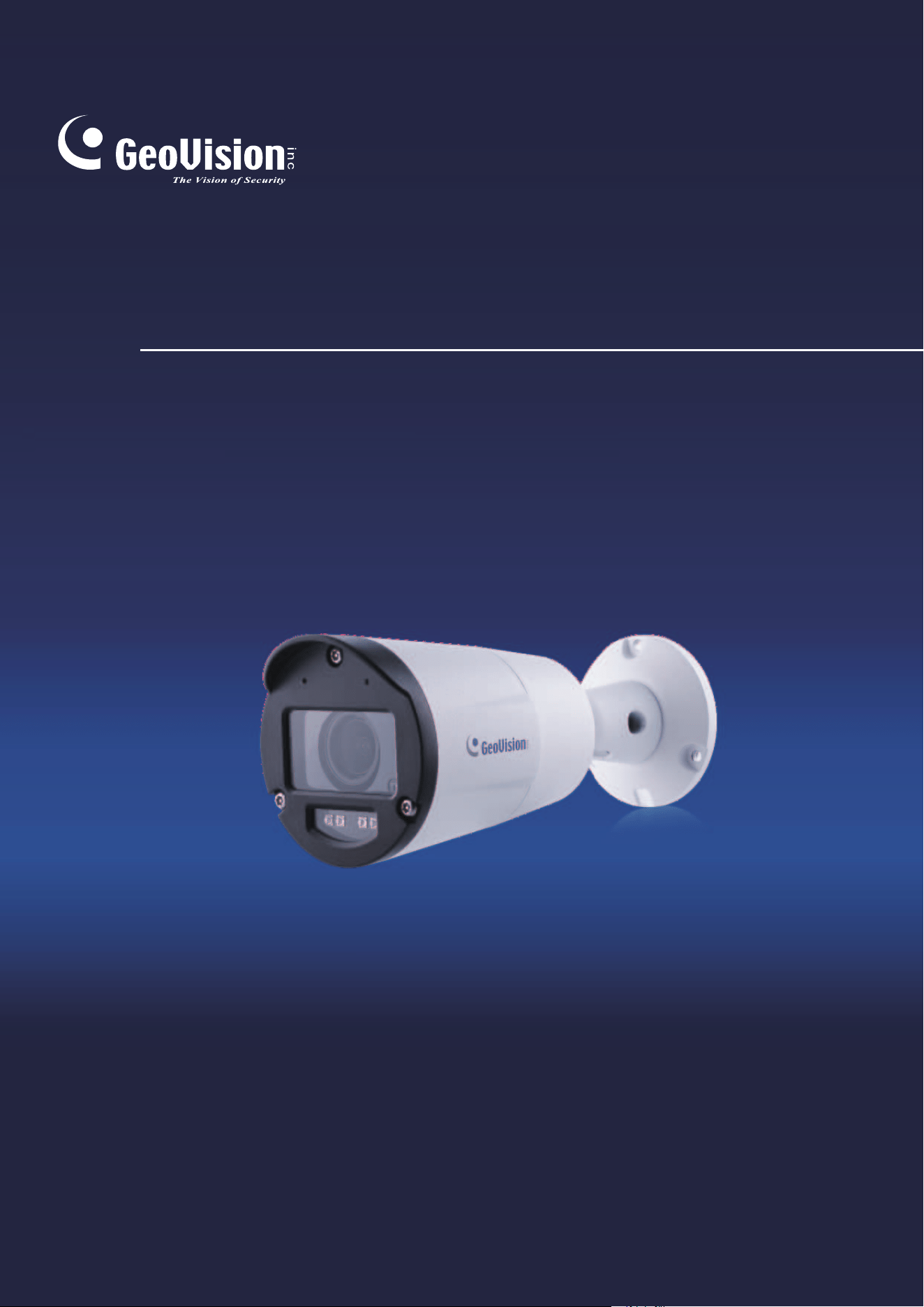
3. Multiple Cameras
⚫ Follow the instructions (1) to (2) in Single Camera. Unless a router fails to
aasign IP addresses by DHCP and camera network setting change to Static
IPv4 address, a unique IP address setting for each of cameras is required.
⚫ Find a camera (default: https://192.168.0.10) and login the web browser with
default account information and connect camera. Go to Network, then choose
Basic, you can change the IP address for the camera. Repeat this process
until each camera has a unique IP address.
8
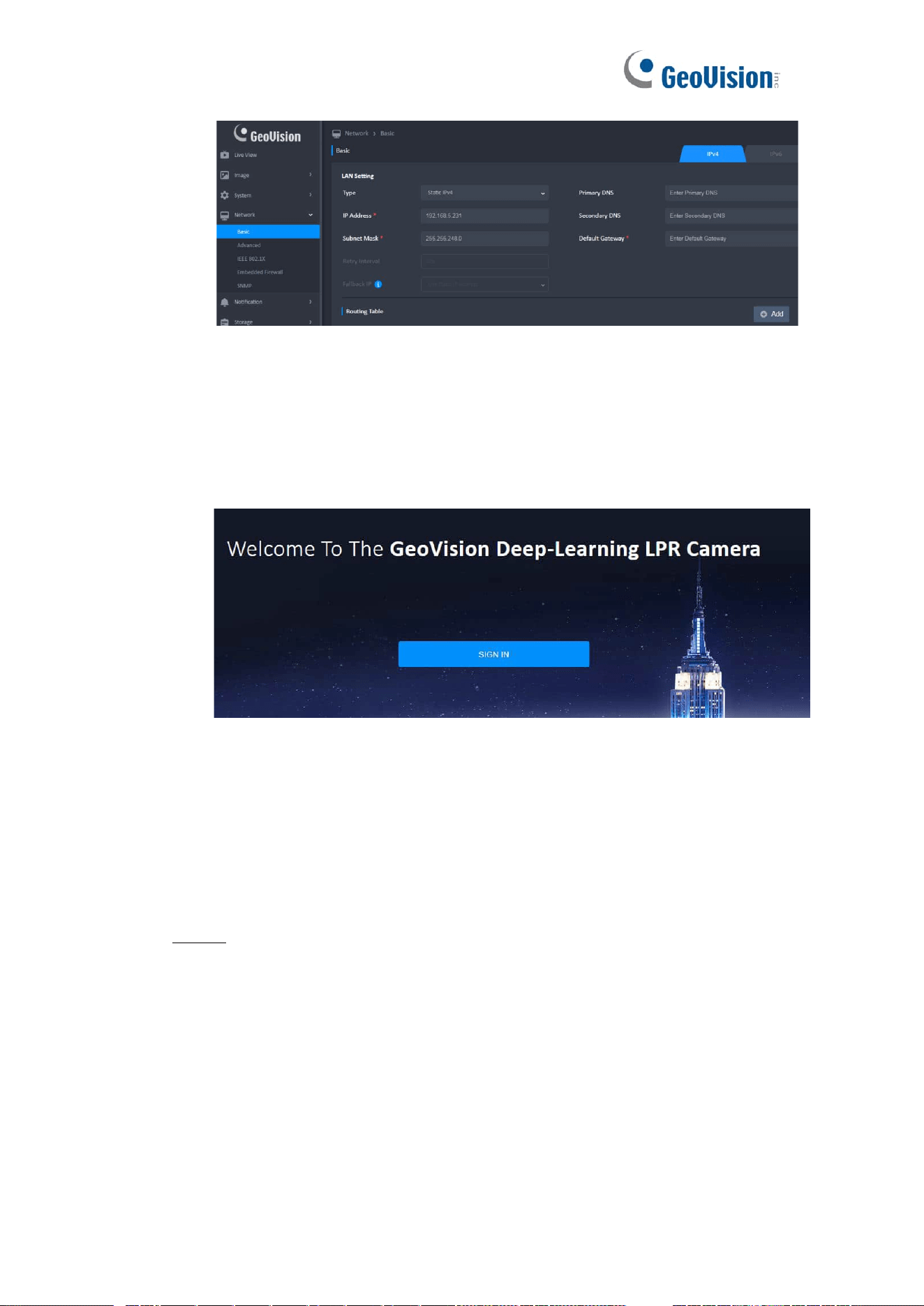
2 Web Interface
1. Log In
⚫ In a web browser, type the IP address of the Network Camera in the address
field can enter the Login Screen.
Note:
⚫ This web interface will change dynamically to the appearance of a website,
depending on the screen size and orientation of the device being used to
view it.
⚫ The web page could be opened by any browser, but full function and bug-fix
only on Google Chrome.
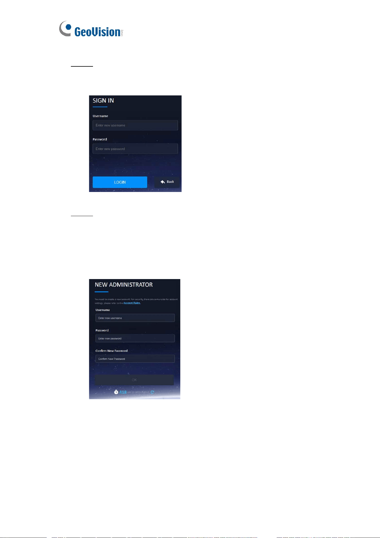
STEP 1
Click Sign in to login the camera web interface.
9
STEP 2
When using the camera for the first time, enter default username (admin) and password
(admin).
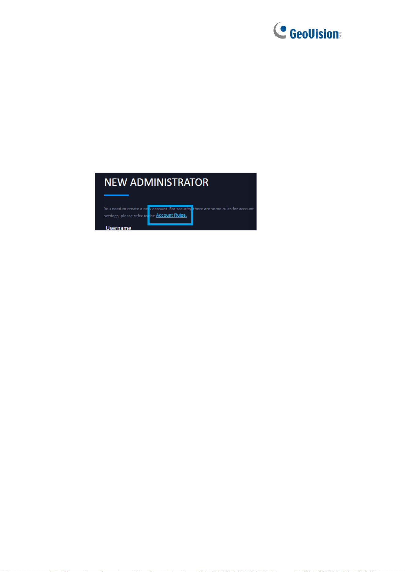
STEP 3
⚫ At initial login to the device, the user must register a new account.
⚫ The default account cannot login after new account (Administrator or User) is
registered.
⚫ Click on the words in the blue area (Account Rules) to see more information
about account rules.
⚫ For security reasons, the web interface will be locked for 300 seconds when
login failed for 3 times.
⚫ Username
➢ Must be 5 to 16 characters, including alphanumeric characters.
➢ Cannot begin with numbers.
➢ Cannot be single character only (ex: aaaaa).
➢ Cannot be default/bad usernames, including admin, opuser, users,
10
guest, mysql, administrator, oracle.
➢ Cannot be the same as registered account username.
⚫ Password
➢ Must be 5 to 16 characters, including alphanumeric characters.
➢ Cannot begin with numbers.
➢ Cannot be single character only (ex: aaaaa).
➢ Cannot be default/bad usernames, including admin, opuser, users,
guest, mysql, administrator, oracle.
➢ Cannot be the same as registered account username.
⚫ More Information
2. Transport Layer Security
⚫ TLS connection
➢ Apply for HTTPS
⚫ Authentication
➢ Apply for HTTPS, RTSP and ONVIF.
⚫ Web/HTTPS
➢ Administrator / User / Operator
⚫ RTSP/ONVIF
➢ Administrator / User / Operator / Anonymous
⚫ Web/HTTPS account username and password
➢ Default administrator account: admin / admin
3. User Permissions for Web/HTTPS
⚫ Administrator has access to all web/camera resources.
⚫ User can only view the live view page.
⚫ Operator can access all network/camera resources.
11
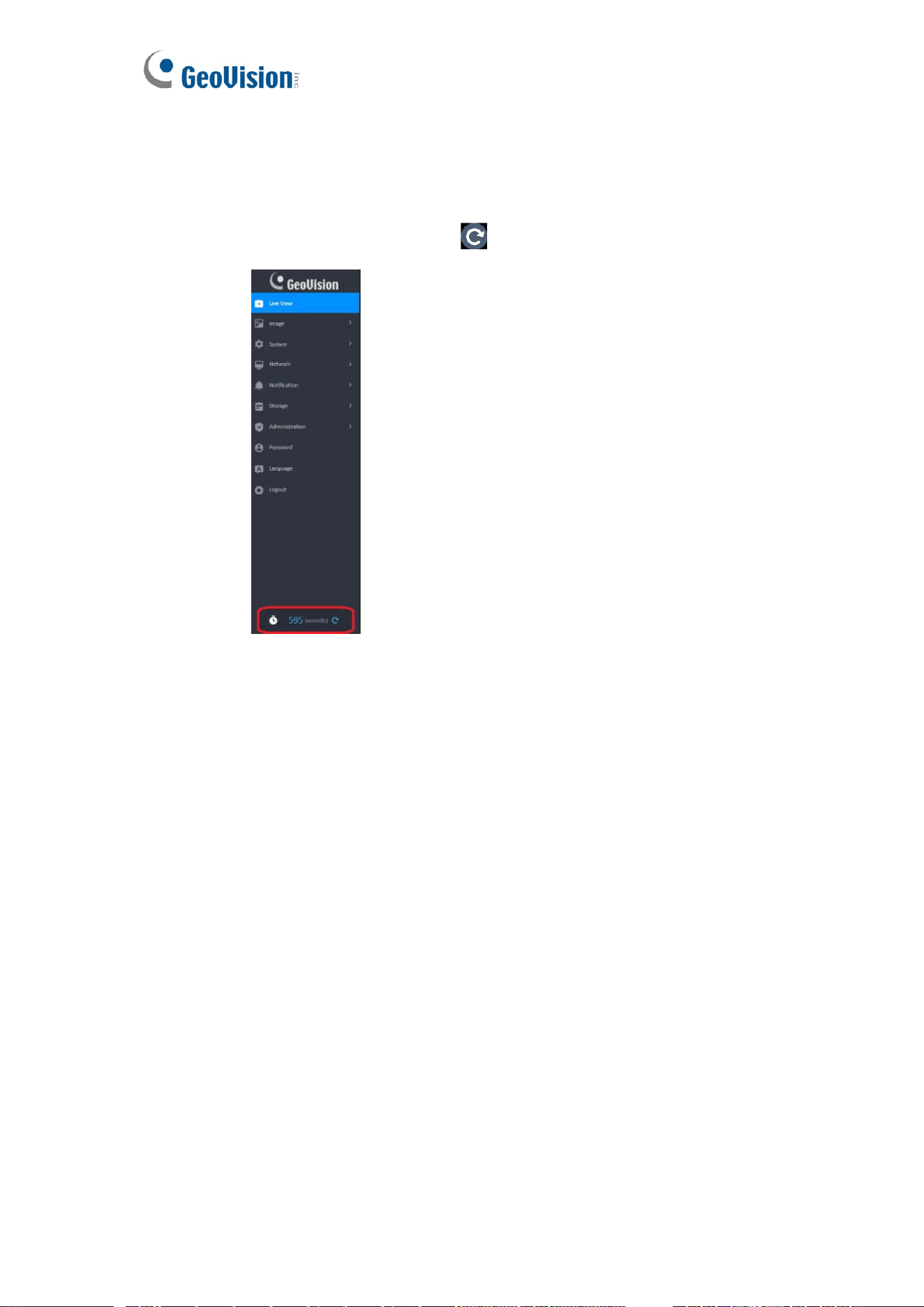
4. Auto Logout
⚫ For security reasons, the web will automatically log out after you have been
idle for 10 minutes (600 seconds).
⚫ The 600-second countdown time is displayed at the bottom of the left menu.
Clicking the Refesh button will restart the counting.
12
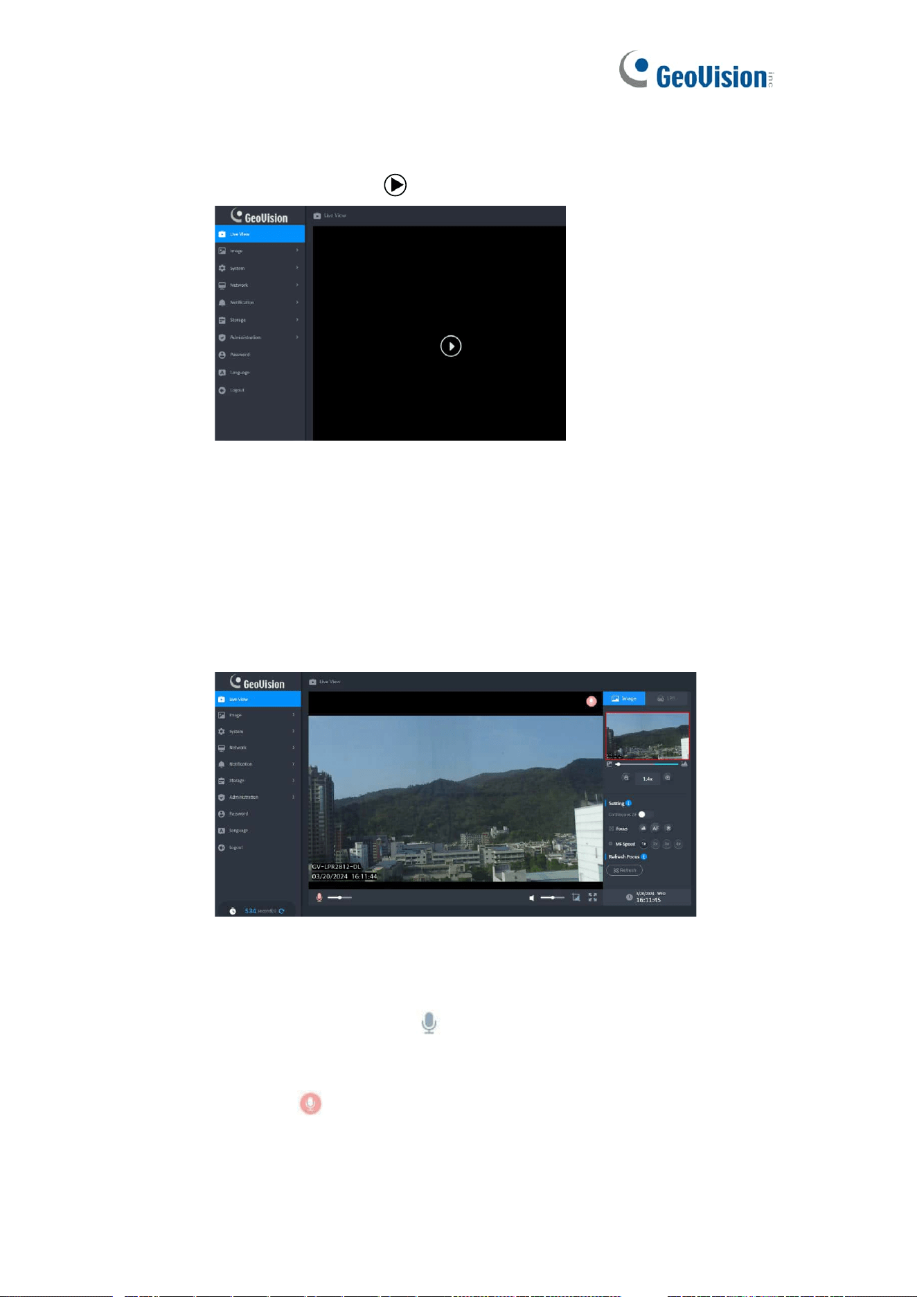
5. Auto play Policy
For security reasons, browser may prevent web from auto play stream. In this case user
needs to click the play button ( ) to play the stream.
3 Live View
1. Overview
⚫ The aspect ratio of screen will be different according to video resolution on
the Live View.
⚫ The Tool Bar is hidden after idle for 3 seconds, but it will be displayed when
the mouse cursor moves on the screen.
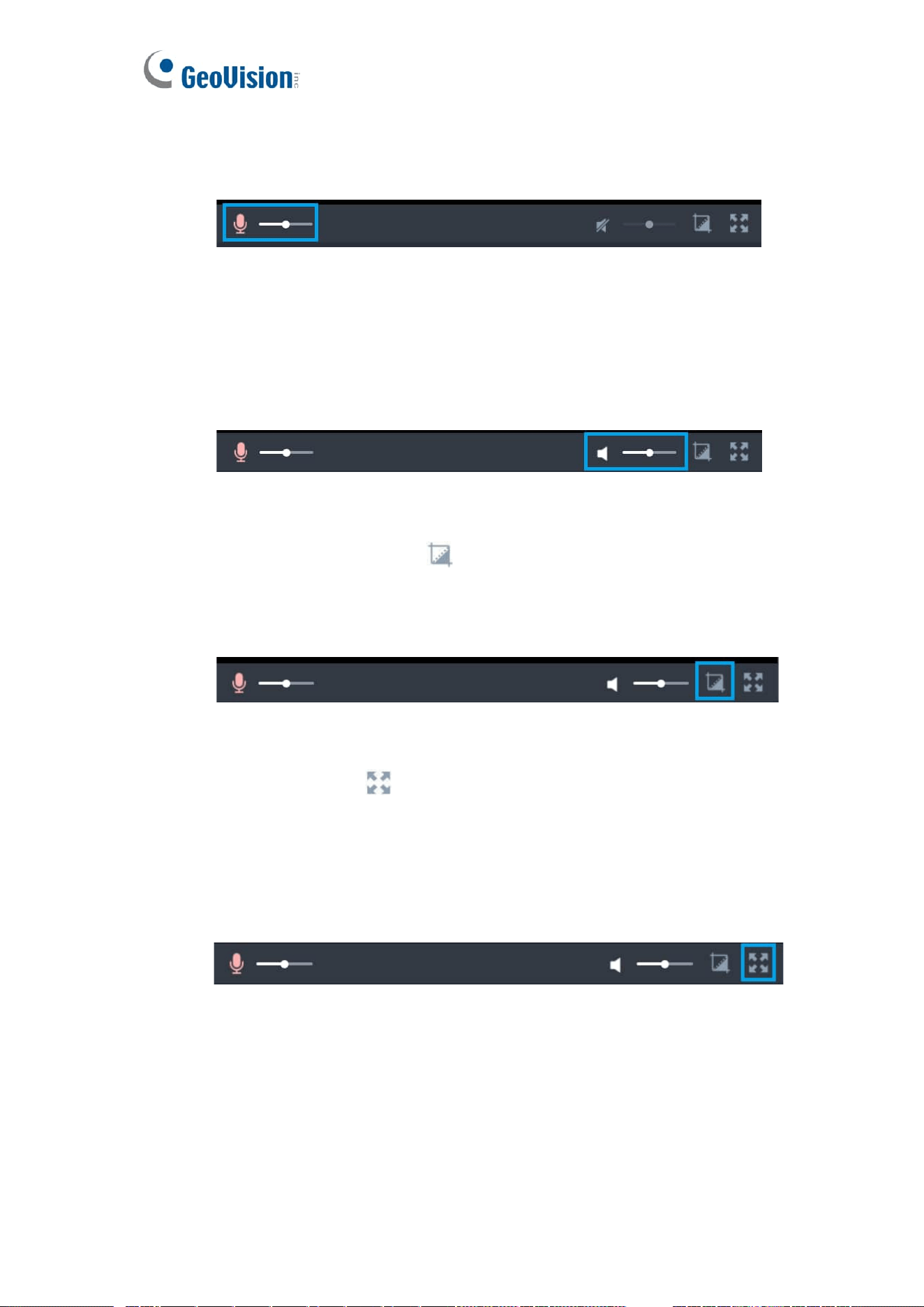
2. Microphone
⚫ The Microphone button( ) is only displayed when microphone has been
installed on the local computer.
⚫ Click the Microphone button to activate the talking feature while Microphone
status( ) on top right corner of the video and click it again to inactivate it.
⚫ The volume slider is hidden and the last volume setting will be remembered
when the Microphone button is inactive (Default).
13
⚫ The volume slider is displayed when the Microphone button is active. [Drag
the slider can adjust the Microphone volume in a range of 0~100 (Default:
50).
3. Volume
⚫ The volume slider is hidden and the last volume setting will be remembered
when the Speaker button is inactive (Default).
⚫ The volume slider is displayed when the Speaker button is active. Drag the
slider can adjust the Speaker volume in a range of 0~100 (Default: 50).
4. Snapshot
⚫ Click the Snapshot button( )will save current frame as a photo of the JPG
file and store it to the folder on your local computer directly.
⚫ The snapshot is named with a prefix “Snapshot_” and a date/time suffix
“yyyyMMdd_HHmmss” (Ex: Snapshot_20190915_080000).
5. Full Screen
⚫ Click the button( ) to enter full screen.
⚫ The Tool Bar is hidden after idle for 3 seconds, but it will be displayed when
the mouse cursor moves on the full screen.
⚫ It supports wheel slide controls zoom in and out in following ways:
➢ When the mouse is placed on a standard screen.
➢ When the screen is full.
14
6. Zoom In & Zoom Out
⚫ Only the Optical Zoom can be maintained when page is switched to full
screen.
7. Focus
⚫ The Speed and Focus will be disabled when Continuous AF is On.
⚫ When the minimum or maximum value is reached, the value does not change
when the button is clicked.
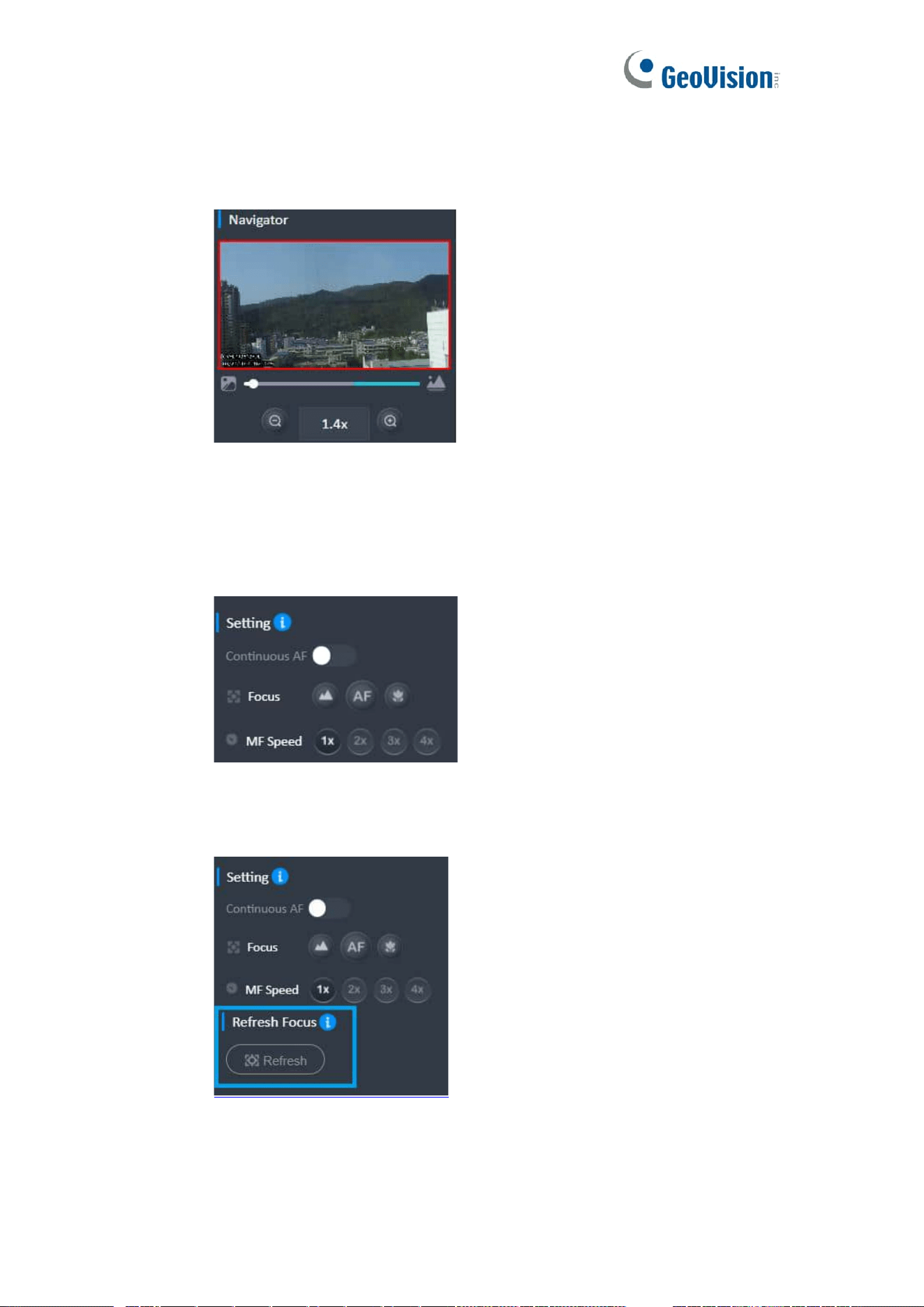
8. Refresh Focus
⚫ Press to refresh the camera focus, which makes it to do zoom/focus again.
15
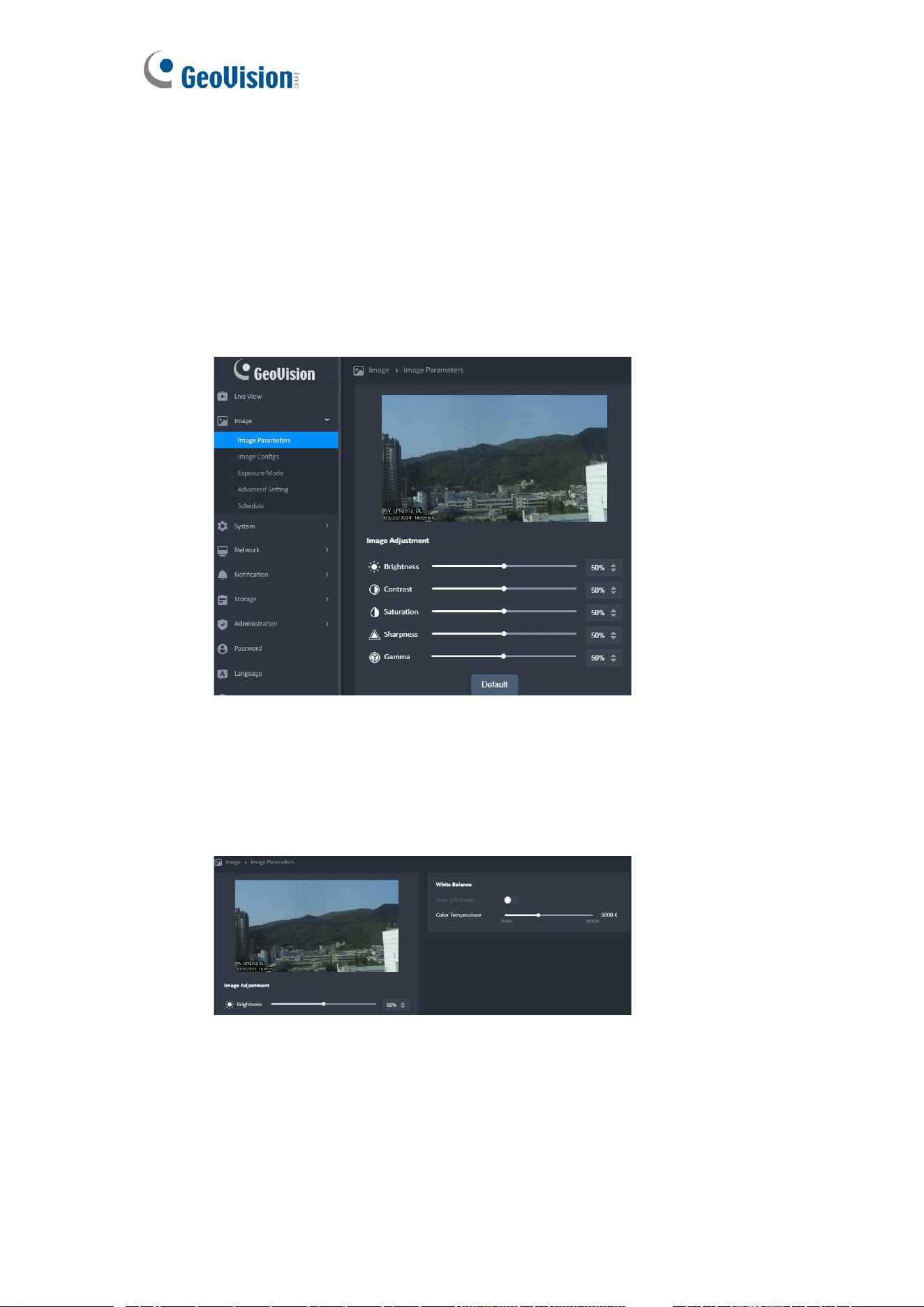
4 Image & Image Parameters
1. Image Adjustment
⚫ The adjusting result will be displayed on Image Parameters Viewer
synchronously.
⚫ When the minimum or maximum value is reached, the value does not change
when the button (▲▼) is clicked.
⚫ When click the “Default” button, It will discard unsaved changes and reset to
default values.
2. White Balance
⚫ The “Color Temperature” can be set when “Auto WB Mode” is off.
⚫ The color temperature adjustment result should be displayed on viewer
synchronously.
16
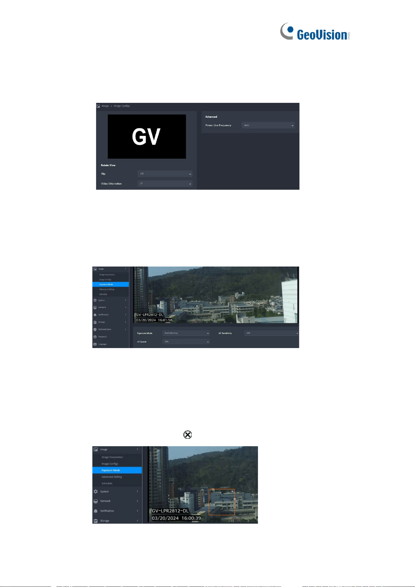
5 Image & Image Configs
⚫ The rotate adjusting result will be displayed on viewer synchronously.
⚫ When the Power Line Frequency is auto , the camera will detect the current
environment is 50Hz or 60Hz, and Exposure Time will change accordingly.
6 Image & Exposure Mode
⚫ There are three Exposure Modes (Multim Metering, Center Metering, BLC)
can be chosen.
⚫ It can create a rectangle for the metering range when BLC metering only.
1. Create a BLC Rectangle
⚫ It needs to create a rectangle for the metering range when using for the first
time or without setting a BLC rectangle.
⚫ Click on the screen to create the range of BLC and display the border in
Orange.
⚫ Click the delete button ( ) can delete the BLC rectangle.
17
⚫ The BLC Rectangle Rules
➢ The available frame size is from 150x150 pixels to 600x600 pixels.
(Default: 150x150 pixels) It cannot be scaled further if it reaches the
minimum or the maximum rectangle size.
➢ The BLC rectangle can be resized to a desired rectangle by dragging
the border. If the mouse cursor hovers over the rectangle or on the
rectangle border, display the border in Orange.
➢ When the mouse cursor hovers the rectangle, change the mouse
cursor to “Move Cursor”. In this situation, the rectangle can be moved
in the Setting Window.
➢ When the mouse cursor hovers over any part of rectangle border,
change the mouse cursor to “Resize Cursor”. The rectangle can be
resized to a desired rectangle by dragging the border.The function can
know the storage about storage for used capacity and total capacity.
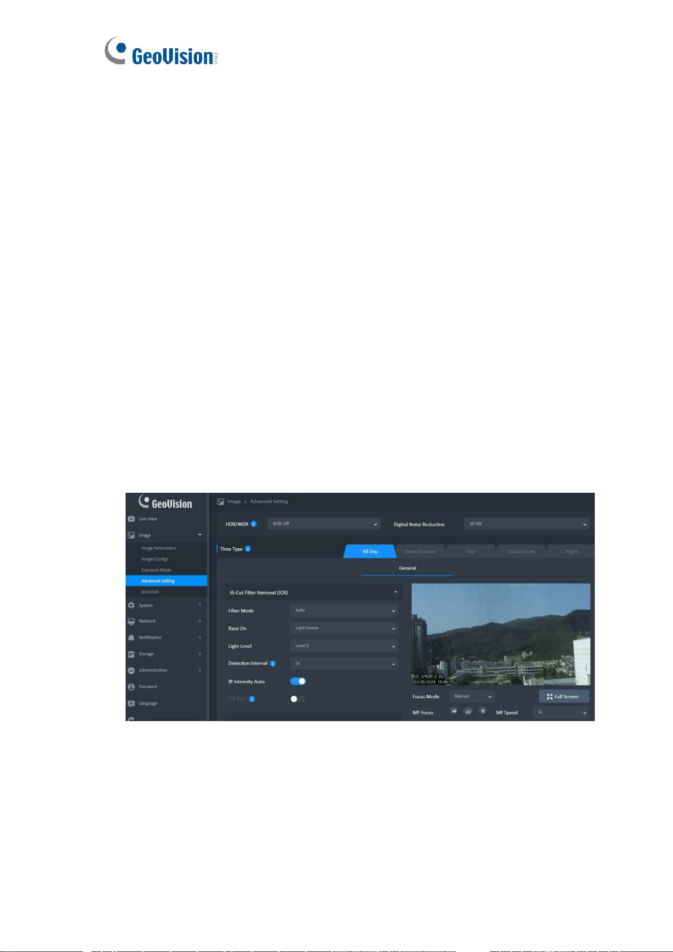
7 Image & Advanced Setting
While in Advanced Setting page, the live view will be the result of applying all the settings
which user is tuning. The different settings according to different schedules will not be
applied while in the Advanced Setting page.

18
1. Components
⚫ Item Bar
➢ Click the main item and list down to show more detailed settings. Only
one main item can be expanded at a time.
➢ The expanded main item should be collapsed automatically before
expanding next one.
➢ If there are too many settings in the item bar, a drop-down scroll bar
will be displayed. Other settings use a fixed range on the page.
2. IR-Cut Filter Removal (ICR)
⚫ When “Filter Mode” is selected Auto, the base on can be set.
⚫ Numbers of sub-tab to be set depends on the status of ICR filter mode and
ICR sync switch.
⚫ Filter Mode: Color / Monochrome / Auto_Light Sensor / Auto_DI ( Day )
3. Exposure
⚫ 3 Modes - Auto / Manual / Priority
⚫ Please note that when any exposure mode is manual, disable “HDR”.
⚫ The maximum value must be equal to or bigger than the minimum value.
4. Levels
⚫ When the general settings is enable ( Digital WDR is On, HDR is On, Digital
Noise Reduction is 3D NR), ”Levels” can set different levels of settings.
5. Navigator Viewer
⚫ All setting values will be used in the image preview and displayed in the
navigation viewer.
⚫ Click the “Full Screen” button ( ) to enter full screen mode.
⚫ The ways to exit full screen mode is as follows:
➢ Press the ESC key on your computer's keyboard.
➢ Click the “Zoomout” button ( ).
⚫ The Tool Bar is hidden after idle for 3 seconds, but it will be displayed when
the mouse cursor moves on the full screen.
19
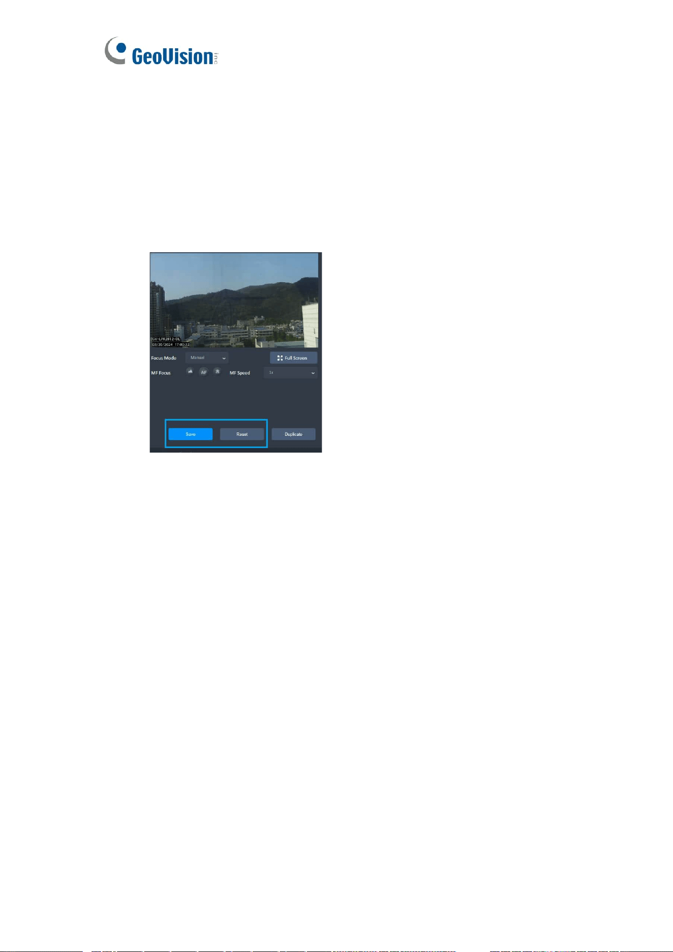
6. Focus
⚫ There are three Focus Modes (Infinity, Auto Focus, Macro) can be chosen.
⚫ The MF Focus and MF Speed can be set only when the Continuous AF is
disabled (see 3-7 Focus).
⚫ There is no Push AF item in the drop-down menu in All Day mode.
7. Save & Reset
If there are any changes, the "Save" and “Reset” button will be displayed
⚫ Reset
➢ The reset function will discard unsaved changes and reset to the saved
value.
8. Duplicate
⚫ Click [ Duplicate ]
⚫ Click [ OK ] to duplicate, or [ Cancel ] to leave
The duplicate function can copy all settings and effects of other time type to
this time tab.
⚫ The copied settings can be modified and unsaved changes will be discarded
unless the Save button is pressed.
⚫ When using duplicate to copy settings:
➢ From “ Period” ( Dawn/Sunrise, Day ,Dusk/Sunset ,Night ) to “All Day”, if
the focus mode is "Push AF", it will be changed to "CAF".
20
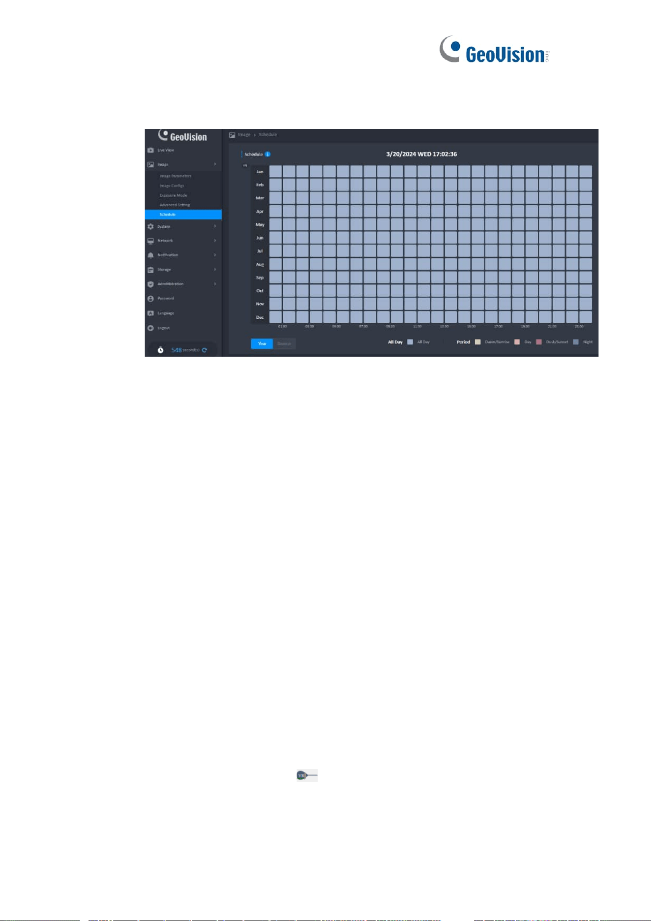
8 Image & Schedule
1. Overview
2. Camera Date & Time
⚫ Display the current time of the camera.
⚫ The date format is based on the camera settings.
3. Year/Season Switch Control
⚫ There are two types ( Year / Season ) of control can be switched.
➢ Year : The year to set.
➢ Season : The 12 months will be divided into four seasons to set.
⚫ The default display of the time type will be different when switch the
Year/Season Switch Control.
➢ Year : All Day.
➢ Season : Period.
4. Year Mode
⚫ Month Bar
➢ The 12 months will be framed in white and you can set the time type ( All
day / Period ) of year when click the Month Bar area.
➢ The mode will be changed immediately when the time type is changed.
Except for not click the “OK” button to close the dialog box.
➢ The Season Label ( ) can not be moved
⚫ Time Range
➢ The mouse hovers over each type range and the range will be framed in
white when the time type is “Period" only.
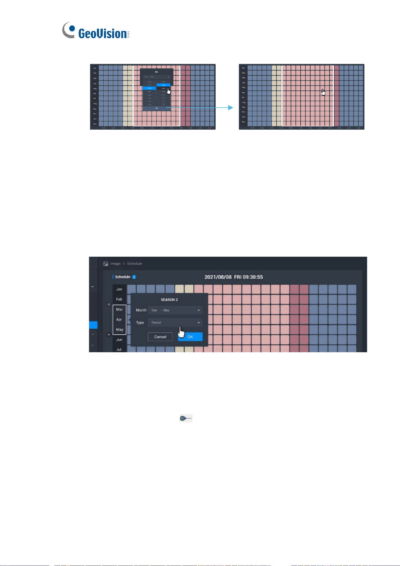
21
➢ Click the time type to pop-up the drop-down menu to set the time range.
5. Season Mode
⚫ Month Bar
➢ The year will be divided into four seasons.
Season 1 : Dec - Feb Season 2 : Mar - May Season 3 : Jun - Aug
Season 4 : Sep - Nov
➢ It can set the “Month Range” and “Time Type” when click the Month Bar
area.
➢ The mode will be changed immediately when the settings are changed.
Except for not click the “OK” button to close the dialog box.
⚫ Season Label
➢ Each label will be placed next to the start month in the season range.
➢ The range of each season can be set 1 - 9 months, and each of the
remaining seasons will have at least one month.
➢ The colors of the season range will be the same.
➢ The Season Label ( ) can not be moved.
➢ The season label can not be changed sort or deleted.
➢ The time type and range in each season can be different.
➢ Modified the season range, the time type will be changed together.
⚫ Drop-Down Menu of Season Range
⚫ Base on the “Start Month”, the end month can be set in the range of 1 to 9
months.
22
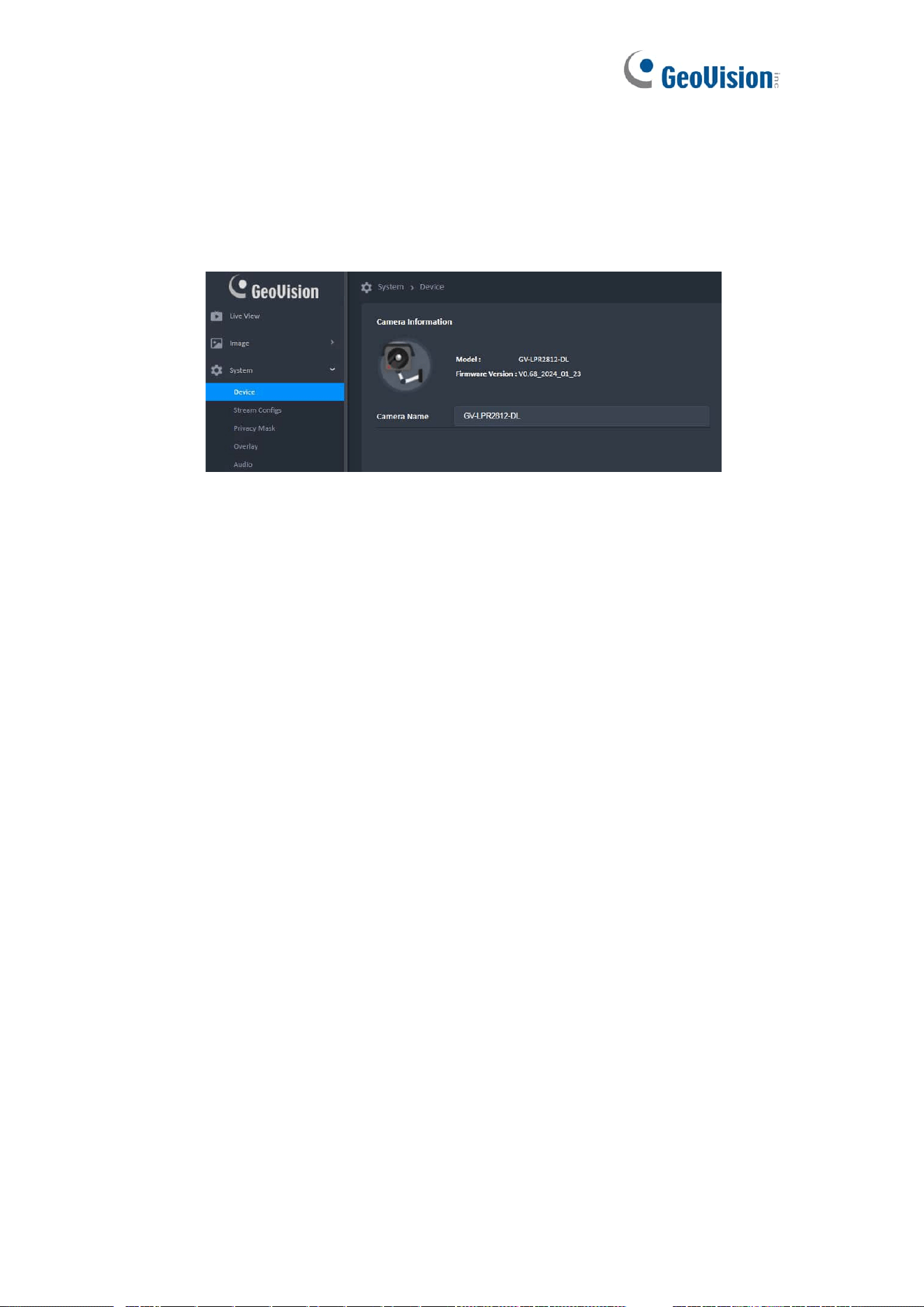
9 System & Device
1. Camera Name
⚫ The camera name can contain up to 16 characters.
⚫ When the page is switched, if the value is invalid, the last valid value is
returned.
2. Date And Time
The Time Zone will be disabled when clock sync is PC.
⚫ NTP
➢ [ Menu ] : Time.google.com (Default )/Time.windows.com/User enters
address manually
➢ Manual input address can be up to 64 characters and the valid
characters are: letters, numbers, periods (.)
3. Time Picker
The Time Zone will be disabled when clock sync is PC.
⚫ Calendar
➢ In calendar, click Left/Right arrow should change the month and display
corresponding dates of the month. Click the digit of date should change
the displaying date on Date Picker synchronously. All clicks inside the
calendar should keep the calendar display on screen.
⚫ Time
➢ Display time, minute, and second on the Time Picker.Can be change the
display time on the Time Picker by swiping up and down the slider on the
right and click on the time number.
23
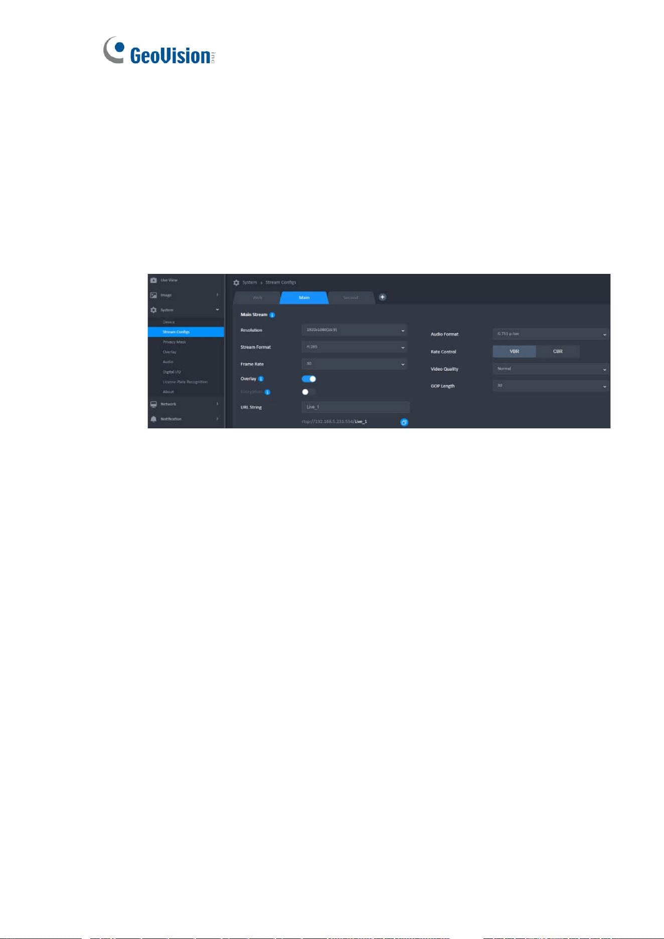
10 System & Stream Configs
1. Web Stream
This is the stream info used on Live view, but the settings in this area cannot be
changed.
2. Main Camera Stream
⚫ Up to 3 camera streams can be created.
⚫ The Save All button should be displayed for any item click or change.
3. Second Camera Stream
⚫ Need to archive the Main Camera Stream to add second camera stream.
⚫ The resolution area of the second stream must be equal to or smaller than the
resolution area of the first stream.
⚫ Stream Format
➢ The Stream Format supports Motion JPEG for the second stream only.
➢ The Rate Control and GOP Length cannot be used when the stream
format is MJPEG.

24
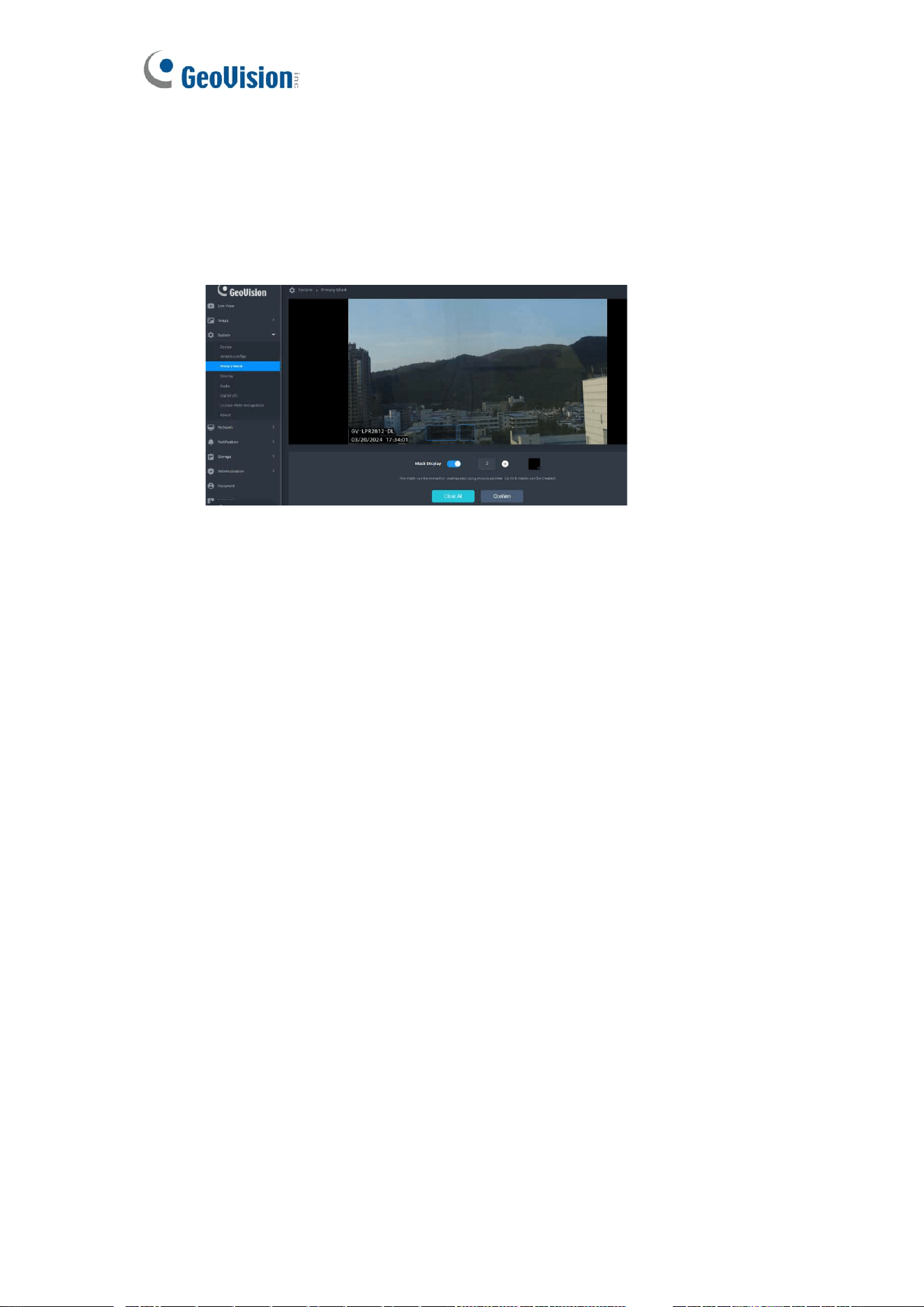
11 System & Privacy Mask
⚫ Click [Add Mask] could add a mask on center of Setting Window. The mask
can be moved or overlapped using mouse cursor. Up to 8 masks can be
created. If the mask has reached the maximum limit, disable [Add Mask] until
masks are less than 8.
⚫ Default Color : Black
⚫ Mask Display:
➢ Click the Switch Box to activate or inactivate the feature about adding the
mask on video stream (Default: On).
➢ Enable the Switch Box only when at least 1 mask is created. If this
feature has been closed, no mask( Mask Preview) will be shown on Live
View Window. But masks on Setting Window should be retained.
1. Mask Status
⚫ Black Block: Mask the area in the video
⚫ Translucent with Orange Border: In active frame, size is editable and can
move the area. Click the [ x ] to delete.
⚫ Translucent with Blue Border: Mask the area in the Mask Preview
2. The Mask Rule
⚫ The mask can be resized to a desired rectangle by dragging the mask border.
If the mouse cursor hovers over the mask or on the mask border, display the
border in Orange.
⚫ When the mouse cursor hovers the mask, change the mouse cursor to “Move
Cursor”. In this situation, the mask can be moved in the Setting Window and
can be overlapped each other. If the position where the “Move Cursor” hovers
is overlapped by two or more frames,only the uppermost frame can be
controlled.
⚫ When the mouse cursor hovers over any part of mask border, change the
mouse cursor to “Resize Cursor”. The mask can be resized to a desired
rectangle by dragging the border.
⚫ The available mask size is from 30x30 pixels to 100x100 pixels. (Default:
50x50) It cannot be scaled further if it reaches the minimum or the maximum
rectangle size.
25
3. Priority of Overlay & Mask
⚫ The current settings will be placed on top in the Overlay Preview and Mask
Preview.
⚫ Overlay has higher priority than Mask on the camera.
Mask Preview
26
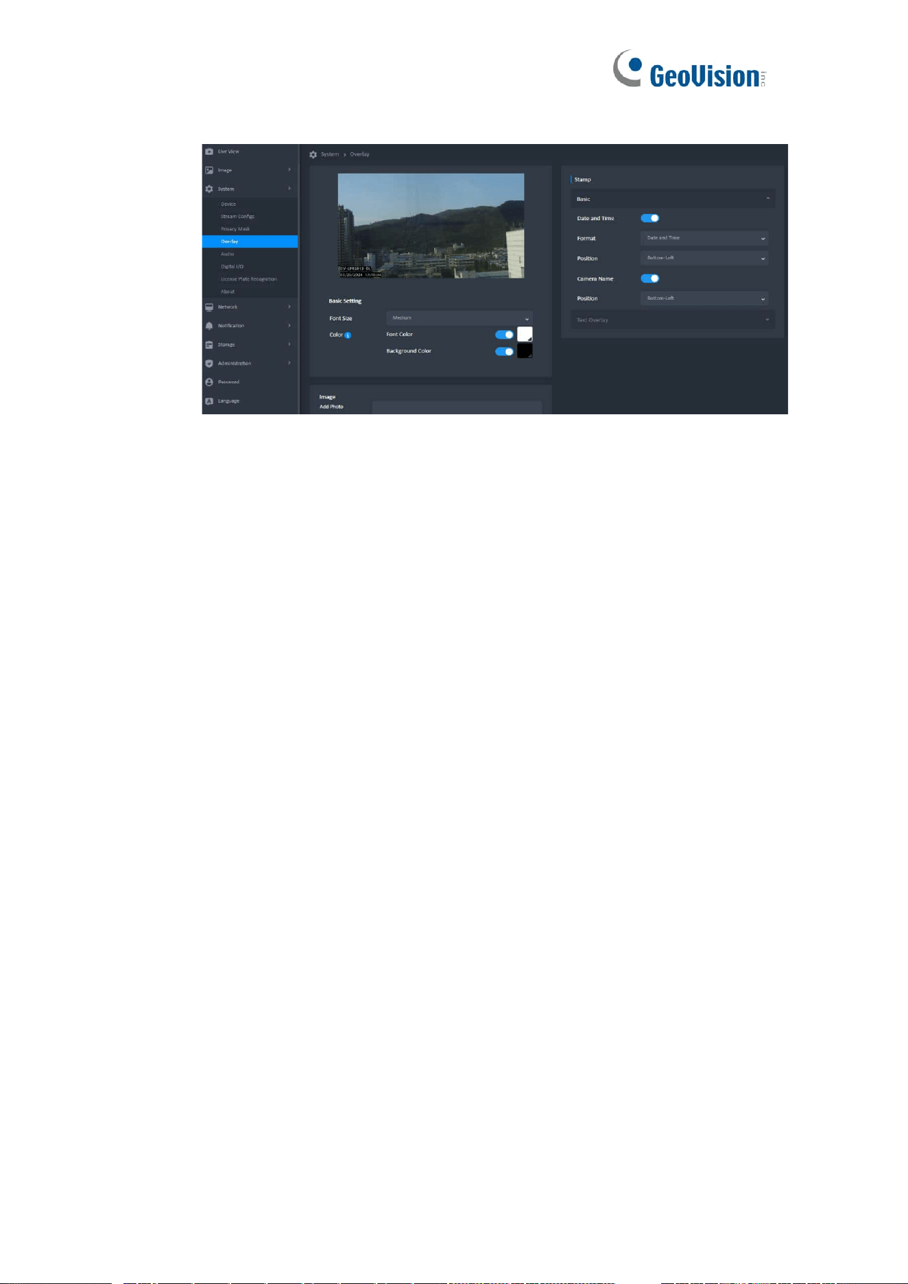
12 Overlay
1. Stamp
Switch button to activate or inactivate the feature of adding the date and time or text
string on video.
2. Overlay Preview
⚫ Can be previewed the overlay settings on the synced thumbnails until click the
Save All button.
⚫ The text type is translucent black with text, and the picture type is block. Both
are displayed at the top of the view.
3. Basic Setting
⚫ Font Size
➢ Click the Select Box to drop down the Font Size list: Small, Medium
(Default), and Large. This setting should be kept and shared for all
resolution.
⚫ Font Color
➢ There are a Color Patch and a Select Boxes on this field. Click the Color
Patch (Default: White) to launch a Color Picker.
⚫ Note:
➢ If the user clicks outside the color picker, it can also be turned off, but the
color cannot be changed.
➢ The color of both text settings will change when clicking on different color
on Overlay Preview.

27
4. Add Photo
⚫ Only one can be uploaded at a time.
⚫ If you upload a new photo, it will overwrite the old one.
⚫ Uploaded the photo have the following restrictions:
➢ The file format is bmp.
➢ The photo width and height should not exceed 384x384, the size should
not exceed 1MB.
➢ The resolution of uploaded photo should not be changed on screen.
5. Position
⚫ Click the Select Box to drop down a list with options: Top-Left, Top-Right,
Bottom-Left (Default) and Bottom-Right.
⚫ The displaying position should be fine-tuned in different aspect ratio.
⚫ Position Rule
➢ If it is the same position on the Below, please put the text string above
the timestamp.
➢ If it is the same position on the top, please the text string below the time
stamp.
⚫ Horizontal Layout
➢ When LiveView is Horizontally, allow displaying the Date and Time, Text
String in the same position, except for the Image.
➢ The font position has a higher priority than the image.
⚫ Vertical Layout
➢ When LiveView is Vertically,the ”Date and Time“ and “Text String” should
be in the same position [ Bottom-Left (Default) ], except for the Image.
➢ The text and image are positioned differently at the bottom and top.
➢ The text position has a higher priority than the image.
13 System & Audio
1. Microphone
28
2. Speaker
Not supported. The camera only supports the microphone, not the speaker.
3. Synchronized with The Live View
The Microphone information needs to be synchronized with the Live View Page.
14 System & Digital I/O
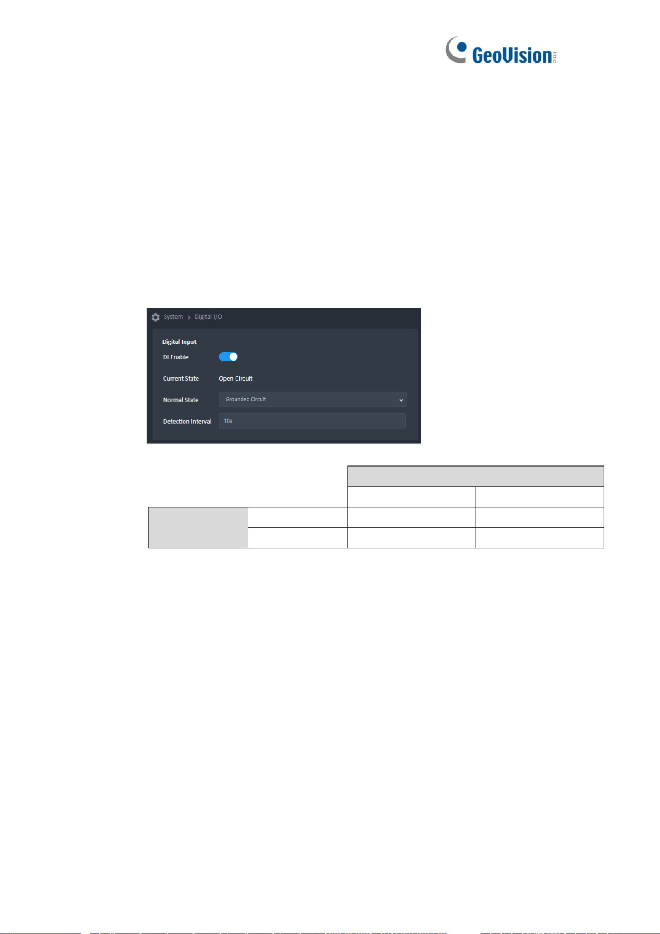
1. Digital Input
When DI is disable = No Event.
Normal State Setting
Open Circuit
Grounded Circuit
Current State
Open Circuit
No Event
Event
Grounded Circuit
Event
No Event
29
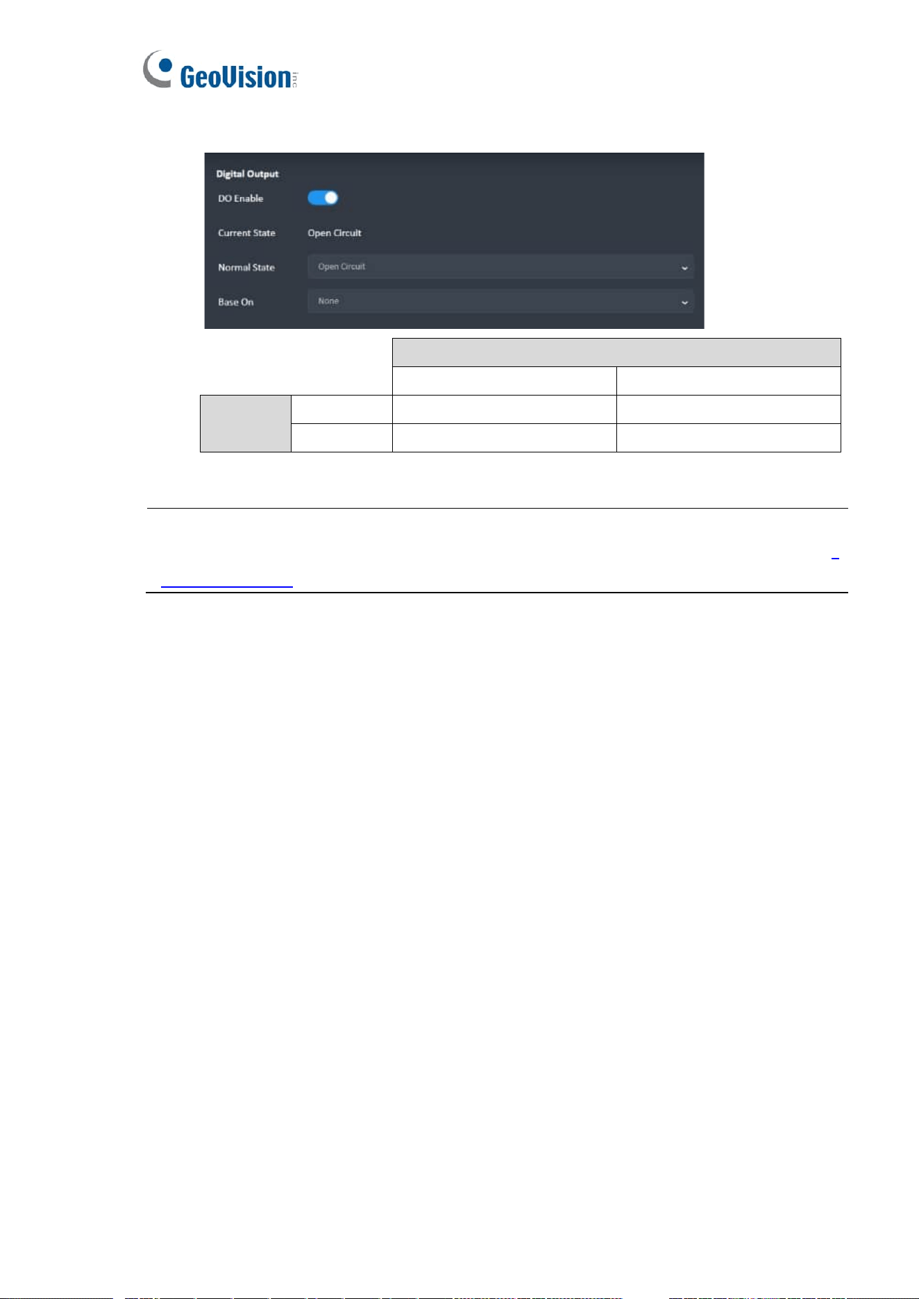
2. Digital Output
DO Normal State Setting
Open Circuit
Grounded Circuit
Event State
Event
DO = Grounded Circuit
DO = Open Circuit
No Event
DO = Open Circuit
DO = Grounded Circuit
IMPORTANT: To open a gate output when a detected license plate number match one in the local
or GV-ASManager databse, follow the instructions in Chapter 5 Configuring the Gate Output of the
Quick Start Guide.
30
15 System & License Plate Recognition
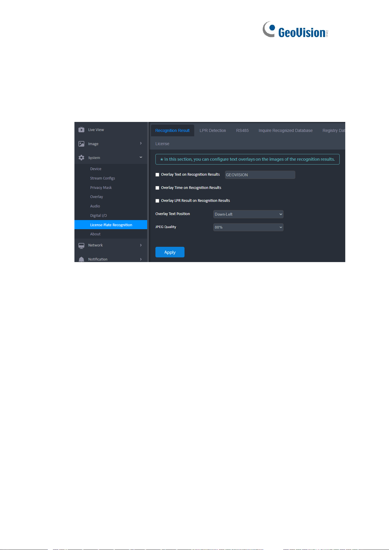
1. Recognition Result
This function displays the recognized plate number, the date and time of recognition, or
any text you specify on the images of the recognition results.
◼ Overlay Text on Recognition Results: Includes a desired text or description
on the images of the recognition results.
◼ Overlay Time on Recognitions Results: Includes date and time stamps on
the images of the recognition results.
◼ Overlay LPR Result on Recognition Results: Includes the recognized
plate number on the images of the recognition results.
◼ Overlay Text Position: Select a position where to display the overlay texts
on the images of the recognition results.
◼ JPEG Quality: Select the quality of the snapshot, from 50 ~ 80%.
31
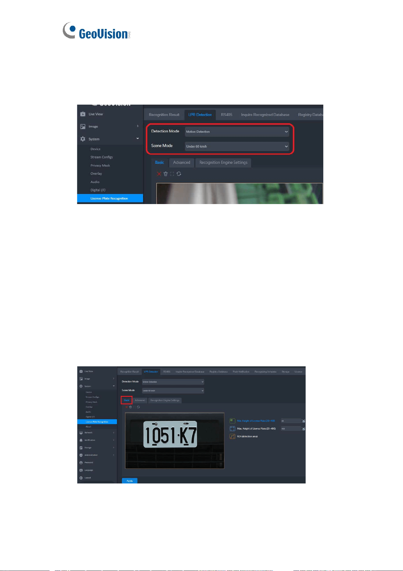
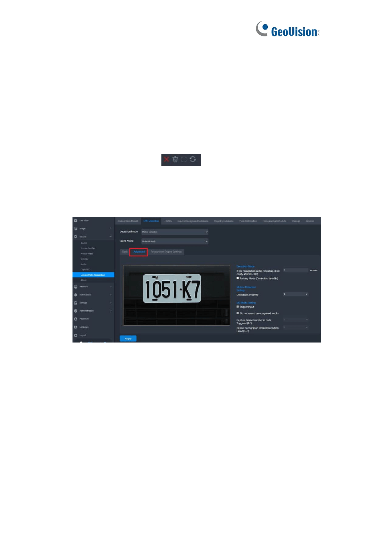
2. LPR Detection
The camera performs license plate detection and recognition when motion is detected or
an input device is triggered. Up to 8 detection areas can be defined for motion detection
and license plate recognition.
◼ Detection Mode: Set the detection mode that activates the license plate
recognition.
➢ Disable: Deactivate detection and recognition.
➢ Motion: Activate recognition by motion detection.
➢ Continuous Detection: Activate for round-the-clock detection and
recognition.
➢ I/O: Used for parking control. The detection and recognition is activated by
input triggers.
◼ Scene Mode: Select the vehicle speed from Under 60 km/h or Over 60 km/h.
[Basic] Set the minimum and maximum height of the license plates to be detected and
the detection area.
32
1. Select Min. Height of License Plate (20~400) and click and drag on the image to
define the minimum height of the license plates to be detected, from 20 to 400
pixels.
2. Select Max. Height of License Plate (20~400) and click and drag on the image to
define the maximum height of the license plates to be detected, from 20 to 400
pixels.
3. Select ROI (detection area) and click and drag on the image to draw the desired
area for license plate detection. Up to 8 ROIs can be defined.
4. Use these buttons at the top of the image to clear settings, maximize the selected
area, or reverse settings:
5. Click Apply.
[Advanced] Set the parameters for license plate detection and recongition.
Detection Mode
◼ If the recognition is still repeating, it will notify after X seconds (0~300):
Specify the duration of time for which a log will be transmitted to GV-ASManager
when the same license plate remains unmoved and under recognition.
◼ Parking Mode (Controlled by ASM): Perform license plate recognition in a GV-
ASManager-controlled parking lot.
Motion Detection Setting
◼ Detected Sensitivity: Select the sensitivity level of motion detection from 1 to 10.
The greater the value, the more sensitive the camera is to motion.
33
I/O Mode Setting
When the I/O option is selected for Detection Mode, the following functions are
available.
◼ Trigger Input: Enable the function that starts recognition when the connected input
device is triggered.
◼ Do not record unrecognigized results: Not to record unrecognizied license plates.
◼ Capture Frame Number in Each Triggered (1~5): Select the number of image
frames captured, from 1 to 5, when input triggers activate the detection.
◼ Repeat Recognition when Recognition Failed (0~3): Select the number of
recognition attempts performed, from 0 to 3, when input-triggered recognition fails.
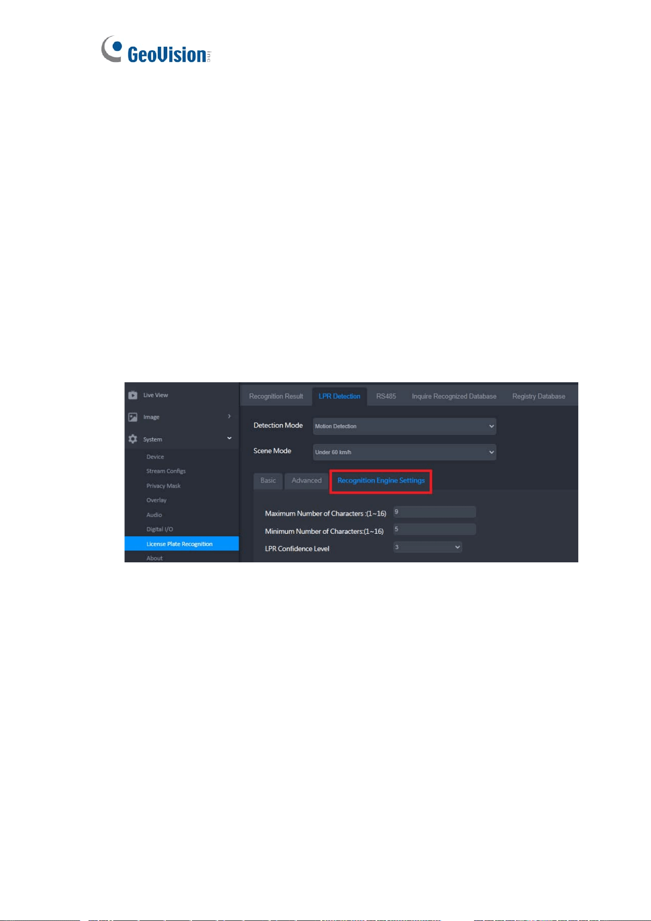
[Recognition Engine Settings] Sets the parameters for the license plate recognition
engine.
◼ Maximum Number of Characters (1~16): Set the maximum number of characters
allowed on the license plate to activate recognition. If the number of characters
exceeds the maximum, the camera will not do recognition.
◼ Minimum Number of Characters (1~16): Set the minimum number of characters
required on the license plate to activate recognition. If the number of characters
does not meet the minimum, the camera will not do recognition.
◼ LPR Confidence Level: The greater the value, the stricter the LPR engine filters
out blurry license plates and only captures clear ones. The default value is 3.
34
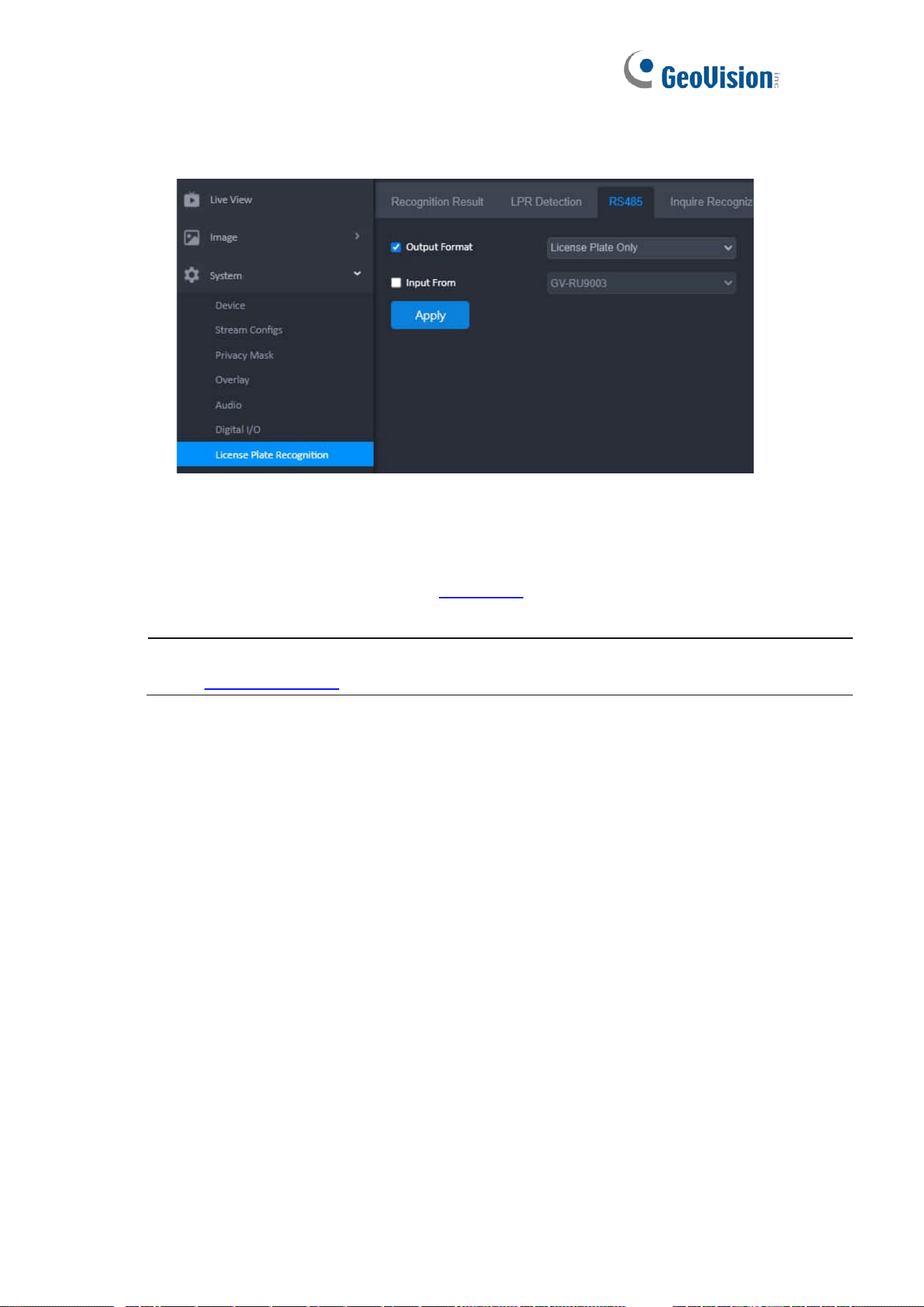
3. RS-485
Users can enable to send or receive data through RS-485.
◼ Output Format: Select the desired recognition results to export through RS-485,
including License Plate Only, License Plate and Time, and License Plate File Name.
◼ Input From: Inputs data from the GV-RU9003 UHF RFID reader.
Note: For the details of integrating the GV-RU9003, see Chapter 8 UHF RFID Reader Integration
in the Quick Start Guide.
35
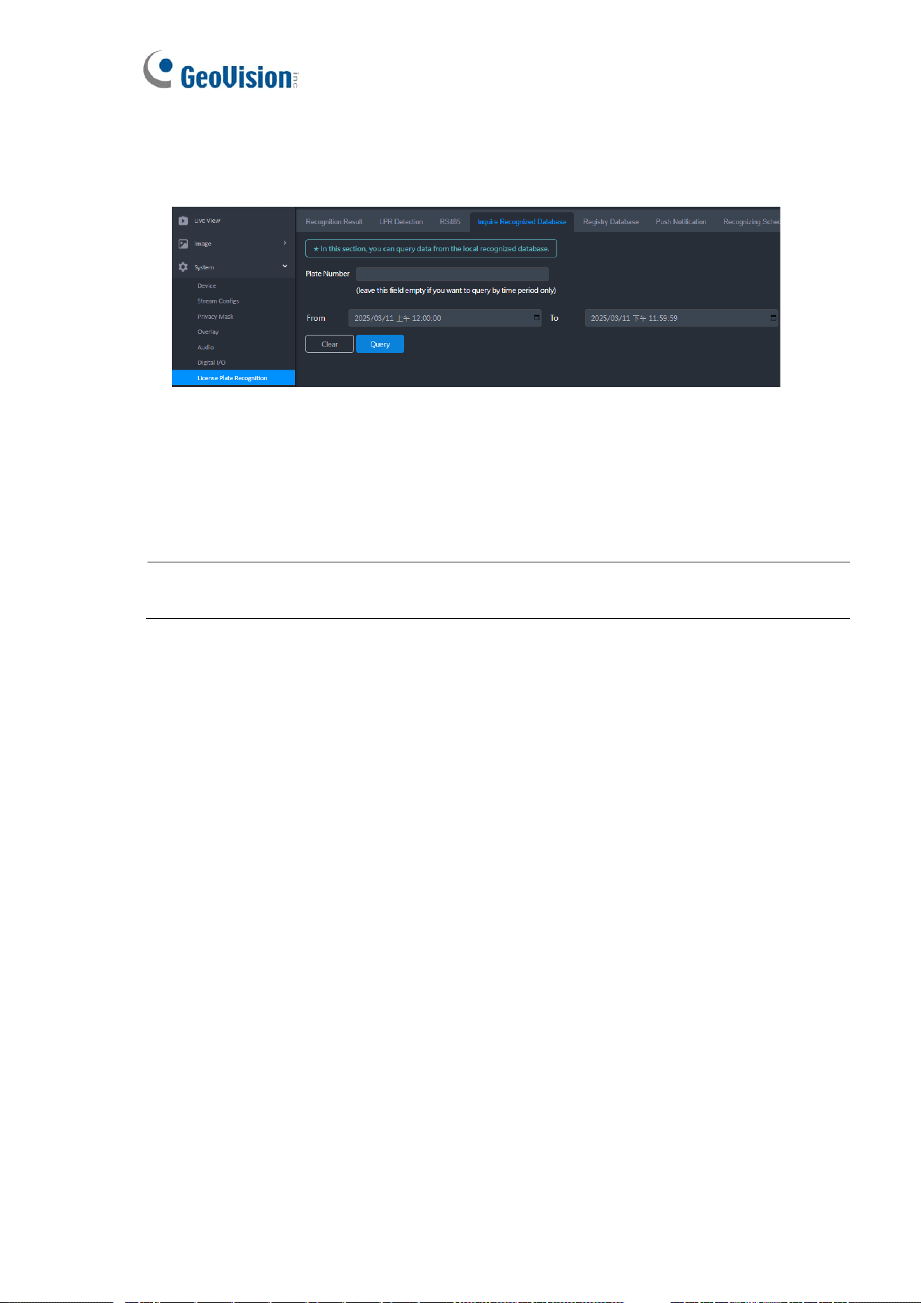
4. Inquire Recognized Databse
Users can search for the history of a license plate number in a database stored on the
memory card.
1. Type a license plate number in the Plate Number field. The entries are case-
sensitive.
2. Specify the start and end dates and times.
3. Click Query to look for license plate numbers on the memory card.
Note: Make sure you have inserted a memory card that contains the database of recognized
license plate numbers.
36
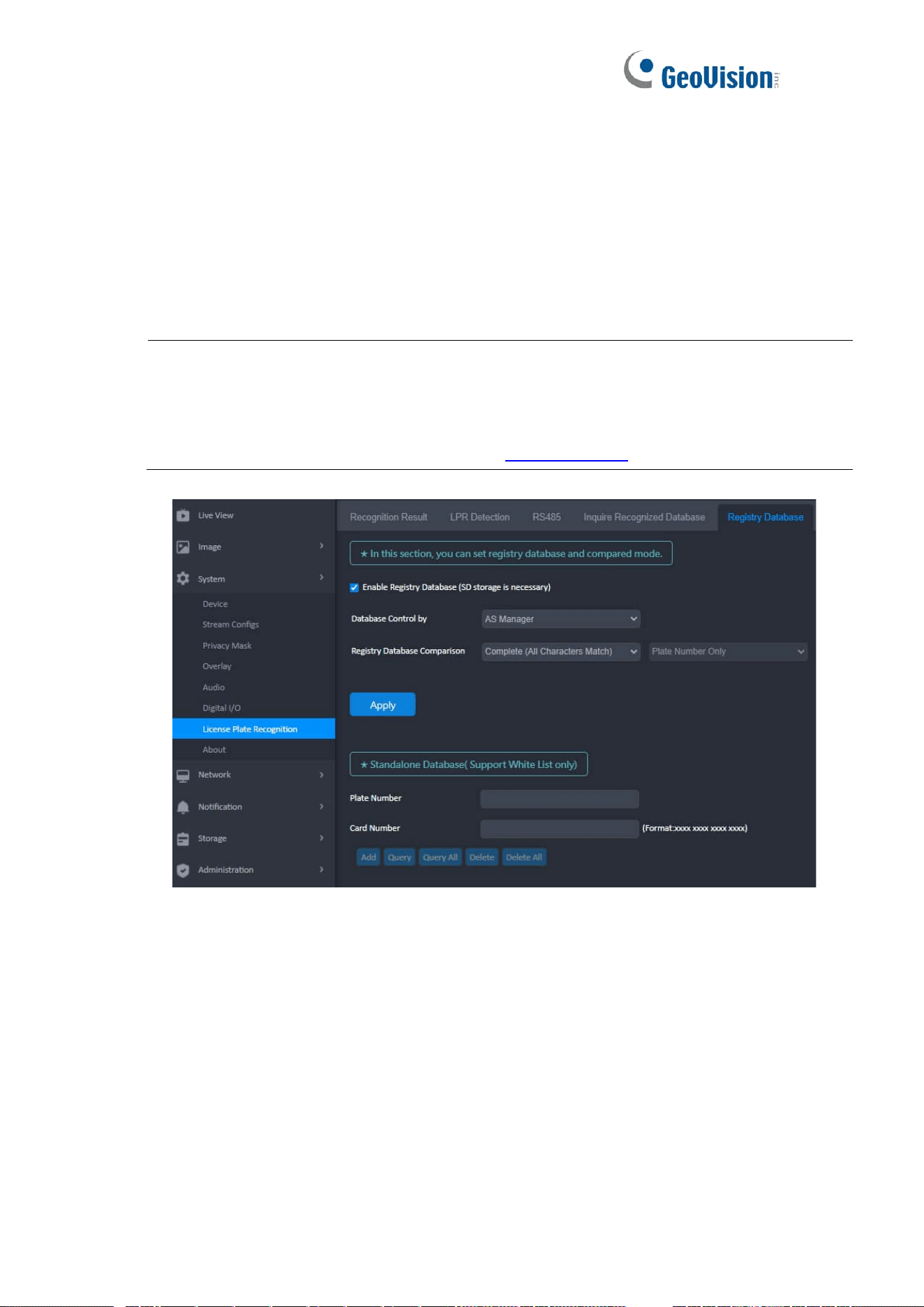
5. Registry Database
Users can set up an output device to activate automatically, such as opening a gate,
when a recognized license plate matches one in the local or GV-ASManager database.
You can either create an independent database on the camera or download the
database from GV-ASManager, an access control and license plate recognition
management software.
Note:
1. GV-LPR2812-DL is supported by GV-ASManager V6.1.2 or later.
2. For details on how to connect to GV-ASManager for access control management, see
Chapter 8 GV-ASManager Integration in the Quick Start Guide.
To set registry database and compared mode:
1. Select Enable Registry Database (SD storage is necessary).
2. Select a database type for Database Control.
◼ AS Manager: Save the vehicle database from GV-ASManager to the
memory card. The connection between GV-ASManager and the camera must
be established first.
◼ Standalone: Activate the Standalone Database. You can manually register
license plates with the camera. See Standalone Database, Support White
List only below. When the feature is enabled, do not connect the camera to
GV-ASManager.

37
3. Select a comparison type for Registry Database Comparison. The recognized
license plate will trigger the output device under the selected condition:
◼ Complete (All Characters Match): The license plate matches every
character of a license plate in the database.
◼ Like (One Character Mismatch): The recognized license plate matches all
except one character of a license plate in the database. The first and last
characters must match those of a license plate in the database.
◼ Somewhat Like (Two Characters Mismatch): The recognized license plate
matches all except two characters of a license plate in the database. The first
and last characters must match those of a license plate in the database.
4. Click Apply.
[Standalone Database (Support White List Only)]
To activate the standalone database, select Standalone for Database Control by, as
mentioned above.
◼ Plate Number: Type a license plate number and click Add to create the
database.
◼ Card Number: Type an access card number to pair the license plate.
◼ Query/Query All: Click the button to search for certain/all license plates.
◼ Delete/Delete All: Click the button to remove certain/all license plates.
38
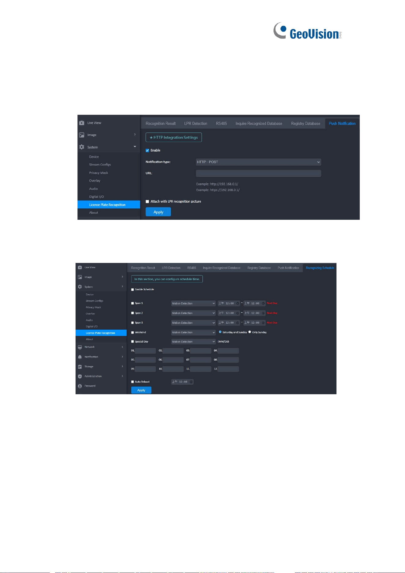
6. Push Notification
The Push Notification function allows users to transmit LPR logs to a JSON server.
Select HTTP – POST from the Notification Type, and type its URL along with its port
value within URL. Select whether to attach LPR recognition pictures with recognition
results.
7. Recongizing Schedule
This page allows users to set up recognition schedules and detection trigger modes.
◼ Span 1- Span 3: Set different time frames during the day for recognition based on the
selected detection mode, Motion Detection, Continuous Detection, or I/O. Each day
can be divided into three time spans, represented by Span 1 to Span 3.
◼ Weekend: Enable this option to start recognition based on the set detection mode
over the weekend, and specify whether it includes Saturday and Sunday or Only
Sunday.
◼ Special Day: Set up to 12 dates for recongtion based on the selected detection mode.
◼ Auto Reboot: Set a daily restart schedule.

39
8. Storage
The recognition results or images are stored on the camera’s attached memory card.
The images are stored in JPEG compressed format.
◼ Enable saving results on a memory Card: Enable this option to save recognition results or
images to the memory card.
◼ Enable recycling: This option allows the camera to overwrite older files when the the memory
card space is lower than the specified limit. If this option is not enabled, the camera will stop
writing data to the memory card when it reaches the specified space.
◼ Keep days (1~254): Specify the number of days to keep files. When both Keep Days and
Enable Recycling are selected, the system applies whichever condition comes first. For
example, if the specified smallest amount of storage space comes earlier than the designated
keep days, then recycle is applied first.
◼ Enable debug message to the storage: Debug messages are deleted after reboot. Select
this option to store log data to the memory card.
40
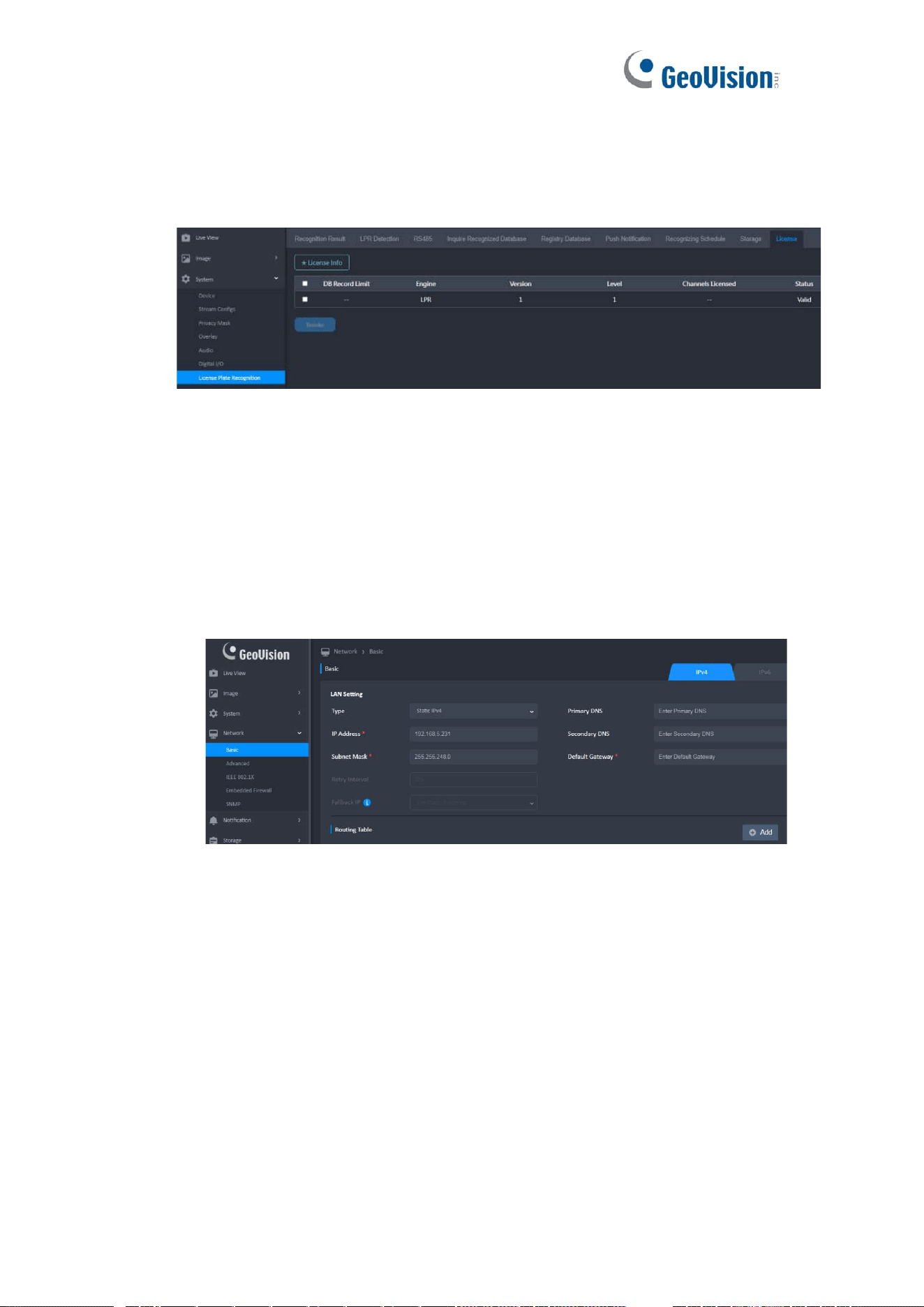
9. License
The License page displays the country and version of the recognition engine currently
installed. The camera can only have the recognition engine of one country at any given
time.
To change the nation of the recognition engine:
1. Contact our sales representatives to request changing the nation of your
recognition engine.
2. Upgrade camera firmware (Administration > Customization) to update the
recognition engine file (.bin) for your new country.
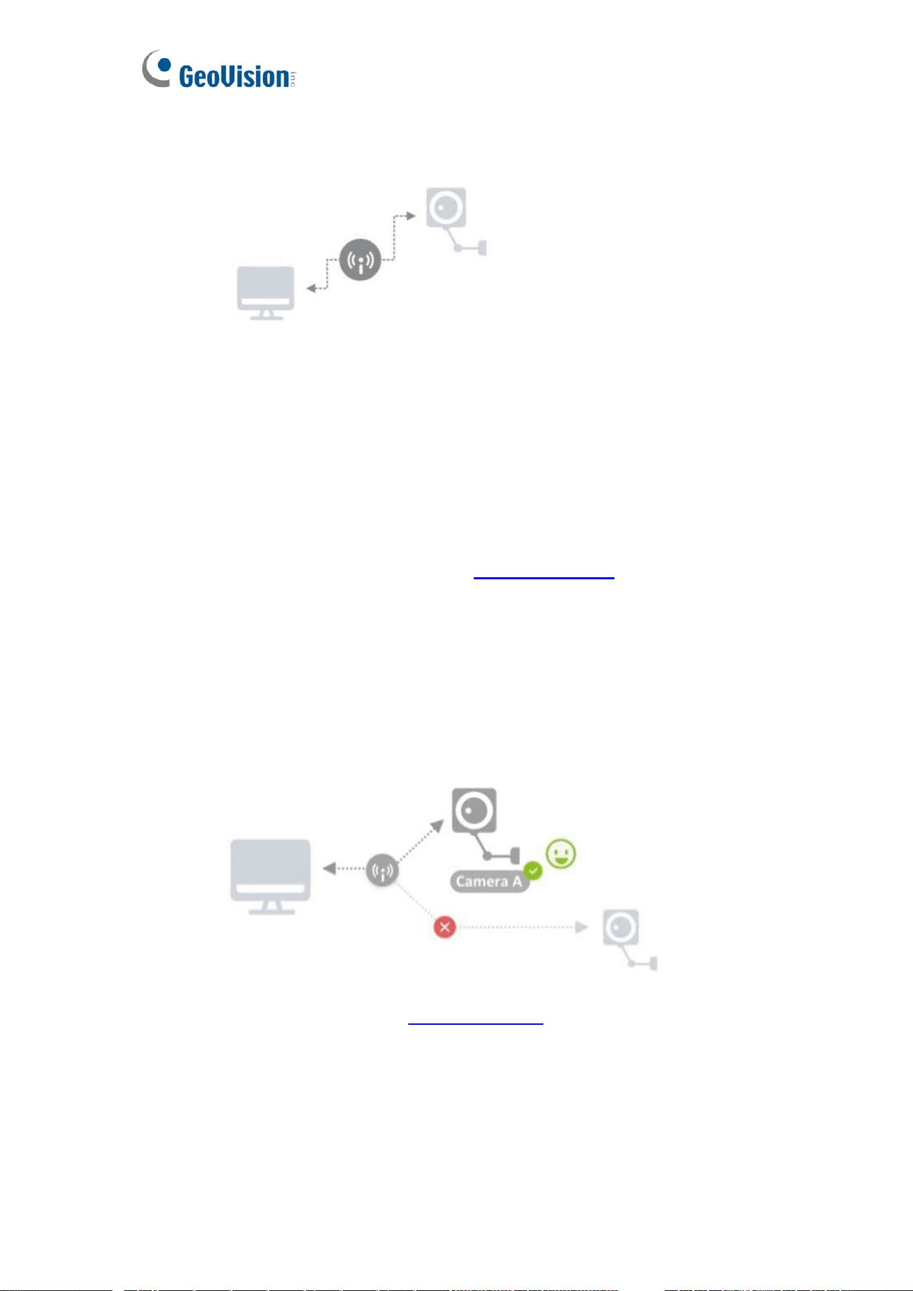
16 Network Basic
1. Different Display Types
⚫ Static IPv4:
⚫ DHCP IPv4:
⚫ Subnet Mask Acceptable Settings
2. Change Network Type
⚫ Change setting if necessary
⚫ Click [ Save All ] Button
⚫ Click [ OK ] to Save & restart the network or [ Cancel ] to leave without
changes
➢ The Dialog cannot be closed when restarting the network.
41
➢ The progress bar and percentage are displayed to show the current
progress
⚫ When the camera network settings have been changed, user may need to
discover and connect camera again
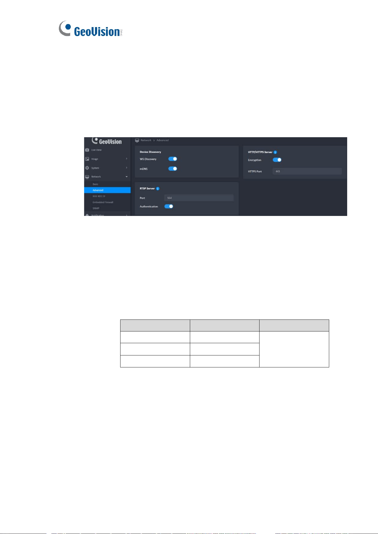
17 Network Advanced
1. Device Discovery
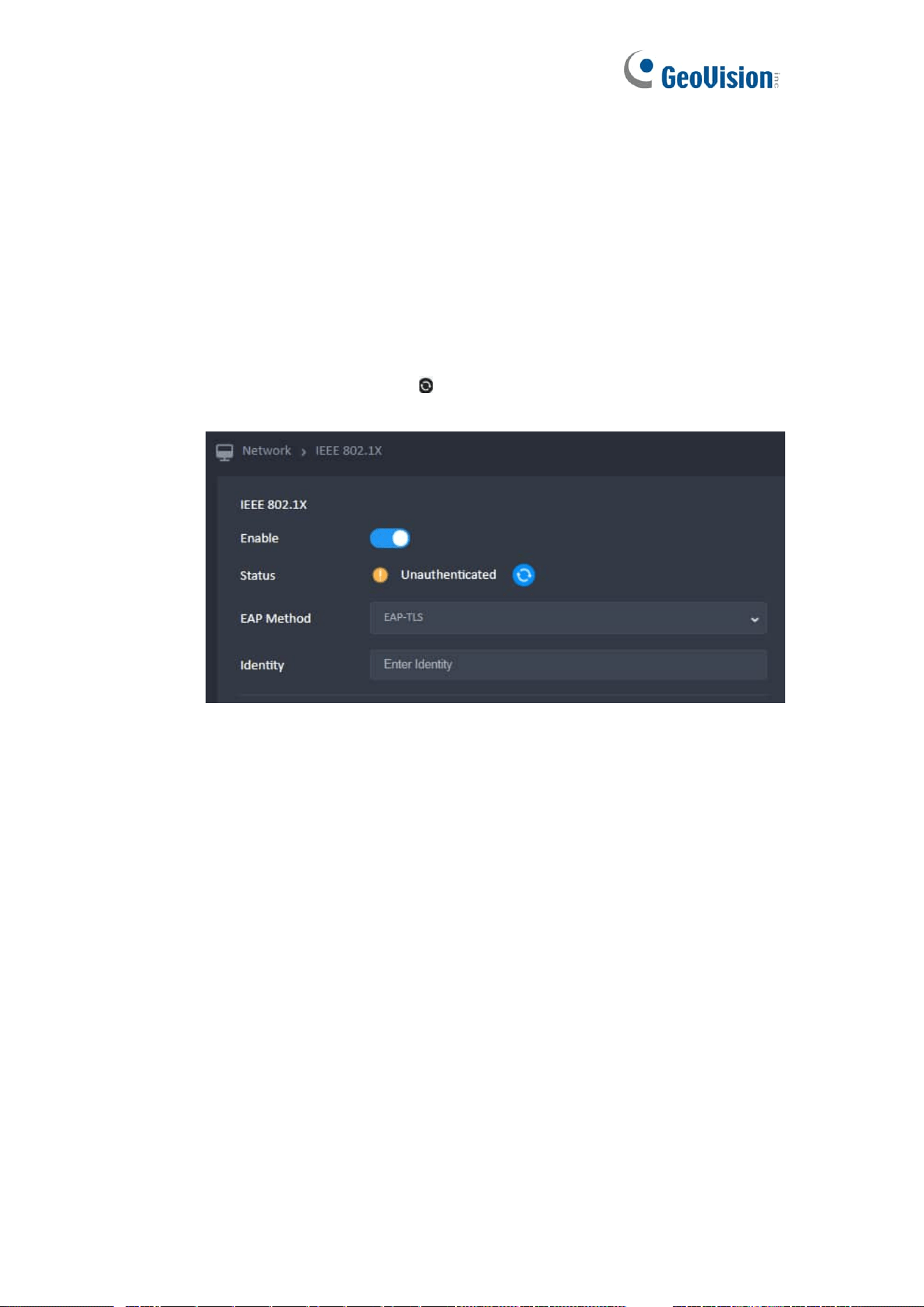
18 Network IEEE 802.1X
Click the Reset button to enable IEE 802.1Xt settings.
1. Upload a File
⚫ Only one can be uploaded at a time.
⚫ The file format have the following restrictions:
➢ Even if the file is corrupted, it can be uploaded.
File Type
File format
Max Size
CA Certificate
PEM/DER
512KB
Client Certificate
PEM/DER
Client Private Key
PEM/DER/PFX/P12
⚫ After necessary files uploaded, the 802.1X connection will still fail in the cases
below.
➢ Camera has corrupted files.
➢ Not using correct files for 802.1X connection.
2. Switch To EAP-TLS
⚫ Click [ Enable ] button
⚫ All the necessary fields must be filed in.
⚫ All input boxes formatted correctly
⚫ Click [ Save All ] button
42
3. Switch To EAP-TTLS / PEAP
⚫ Drop Menu and select
⚫ All the necessary fields must be filed in.
⚫ All input boxes formatted correctly
⚫ Click [ Save All ] button
4. Refresh
⚫ There are two ways to update the file list :
➢ a.) Click [ Refresh ] button.
➢ b.) Re-enter the IEEE 802.1X page.
43
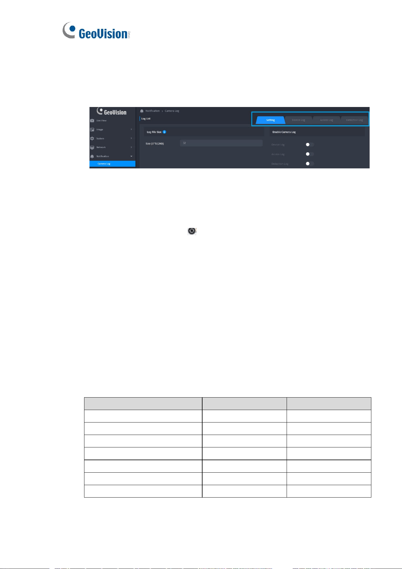
19 Notification – Camera Log
1. Setting (Default)
⚫ There are three types (Device Log, Access Log and Detection Log) of logs can
be recorded.
2. Log List
⚫ Display the log according to the conditions made from “Date & Time” in order.
⚫ The newest message will be displayed at the bottom.
⚫ Click the Refresh button ( ) should refresh the Log List.
3. Export
⚫ Click the [ Export ] button
⚫ Click [ OK ] to export
⚫ If there is no record on the page, the “export” button will disappear.
⚫ The export file should be named with a prefix “(Log Name)_(Order)” (Ex:
Device Log_1).
⚫ Camera will keep 2 log files.
⚫ Show the notification when saved the file.
⚫ There are two ways to close the notification :
➢ Click [ OK ] button.
➢ After 3 seconds.
⚫ The List of Log
Device Log
Access Log
Detection Log
boot result
user login
Digital Input
camera serial number
user logout
Motion Detection
camera firmware version in use
user login failed
Tampering Detection
camera program errors
user block in blacklist
AI Detection
setting changes
configuration backup
configuration restore
Note: The AI Detection log records LPR events.

44
20 Notification – Event Setting
All defined events will be listed in the Event List with item, trigger, notify, schedule, enable
and operation.
1. Add New Event
⚫ Up to 16 events could be added.
⚫ Click the ( Add ) button
⚫ Complete the dialog
⚫ Click [ OK ] to add new event list
⚫ The ( Add ) is hidden if it has already been added 16 events. Display this
button again if the events are less than 16.
⚫ Trigger
➢ There are multiple trigger sources for setting. Only 1 trigger can be set
for each event setting.
⚫ Notify
➢ One or multiple methods can be selected.
➢ Display method string when only one method has selected ; Display
“Multiple Methods” when selected more than one method.
⚫ Schedule
➢ There are two time mode (All Day, Period) for setting. Only 1 mode can
be set for each event setting.
➢ If the “Target Day” and “Target Time Slot” are not set when the time mode
is Period, the “OK” will still disable to add new event.
➢ End time must be greater than start time.
2. Event List
⚫ Select Individual Event
➢ double-click to edit the event
⚫ Select All Event
➢ The delete button is enabled when event is selected

45
3. Edit Event
⚫ Click the edit button ( ) or double-click list to edit the event items of the event
settings.
4. Delete the Event
⚫ The Delete button can be used at the top.
⚫ Tap the Delete button.
⚫ Click [Cancel] to close this message or [OK] to delete the event setting.
46
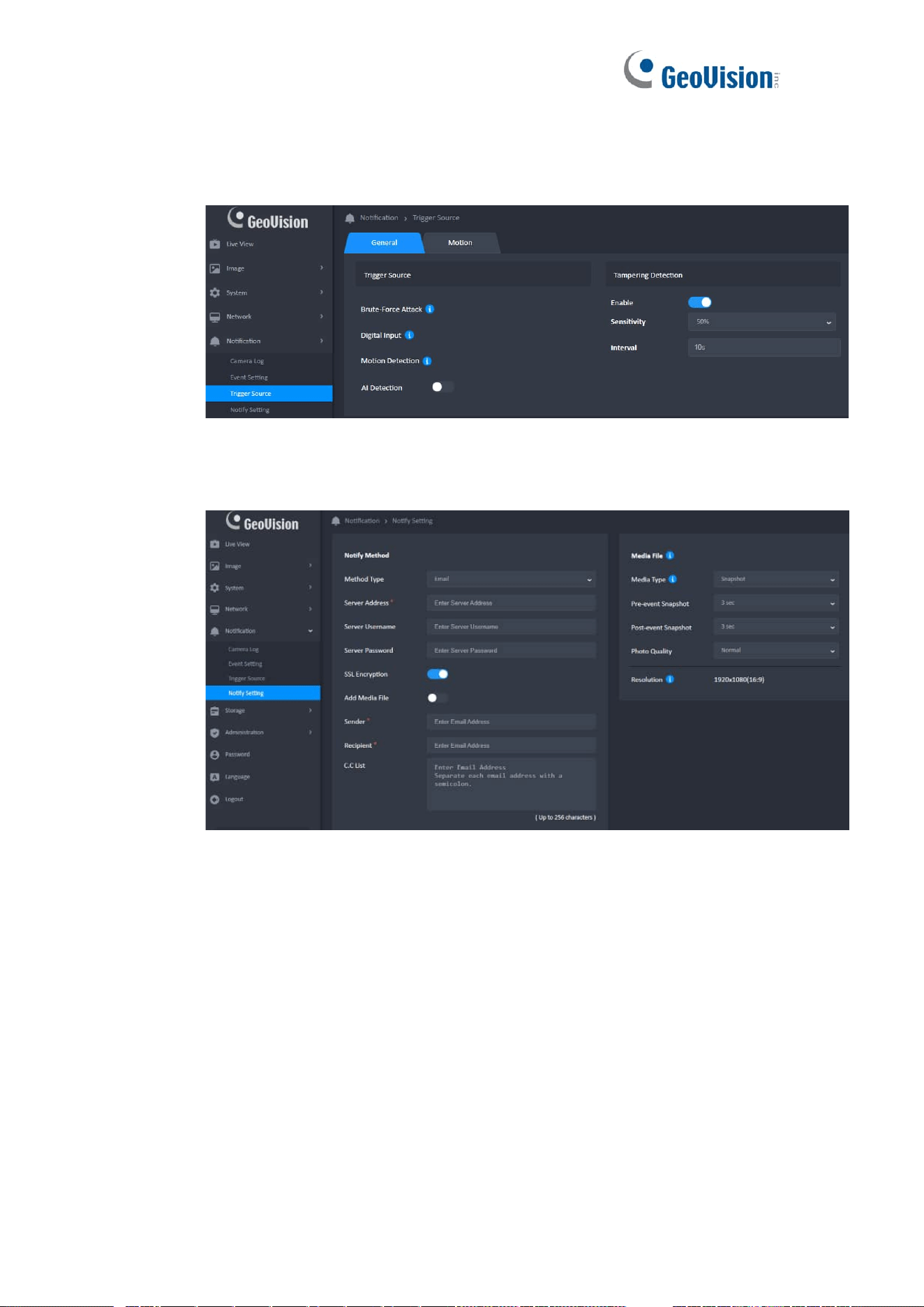
21 Notification - Trigger Source
Each trigger source has a switch on right side. Click the switch could enable or disable
the trigger.
22 Notification - Notify Setting
1. Notify Method
The forms will be different based on ”Method Type”.
⚫ Email CC List Flow
➢ Click the “Test” or “Save All” button, if the CClist has input text
➢ Ensure valid characters in the C.C list
➢ Ensure format correct in the C.C list
➢ Test button: Pop-up the test dialog
47
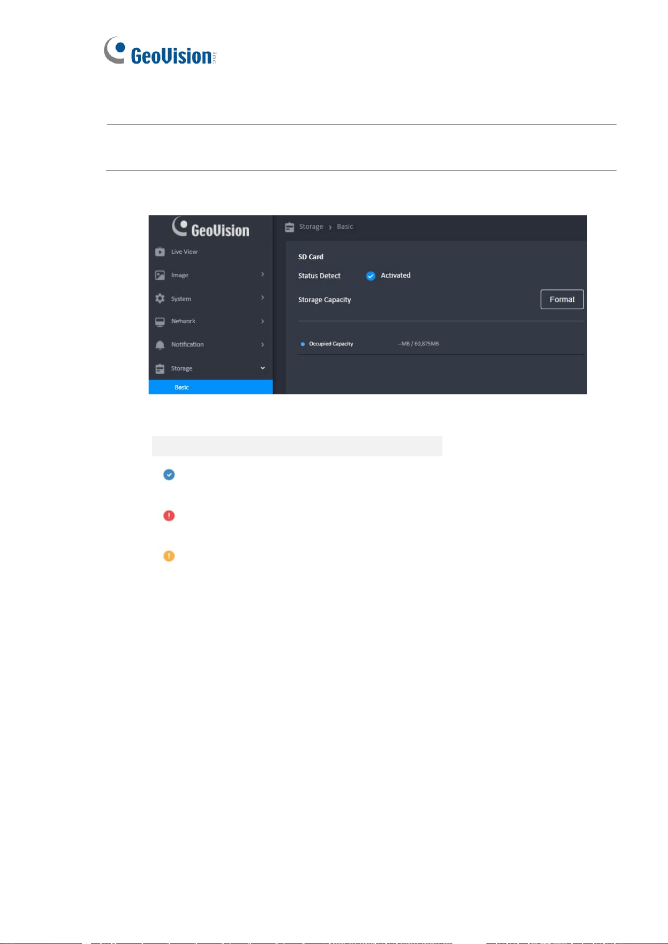
23 Storage
Note: GV-LPR2812-DL does not have a recording function. The SD card only stores LPR captured
photos and logs.
1. SD Card
⚫ Status Detect
Display
Activated
No Card / Format Error
Disk Full \ Not Healthy \ Recording Full
⚫ Occupied Capacity
The function can know the storage about storage for used capacity and total
capacity
⚫ Recording Capacity Used
The function can know the storage about recording storage for used capacity and
total recording capacity
⚫ How To Format
➢ Hover/Click the [ Format ] button
➢ Click [ OK ] to format
➢ Note: Formatting will into the FAT32 System and erase all files on the SD
Card

48
⚫ Settings for Recording Capacity
If the SD card capacity is less than 4096MB, recording capacity setting will be
disabled and recording function will also be disabled.
⚫ SD Card Re-detect
While camera reboot with SD card inserted, or SD card is inserted while camera is
running, camera will detect the SD card capacity

49
24 Administration
1. Firmware Update
⚫ IMPORTANT: For camera firmware upgrade, refer to the Technical Notice .
2. Backup & Restore
⚫ The backup file should be named with a prefix “CAM_Backup_” and a
date/time suffix “yyyyMMdd_HHmmss” (Ex:
CAM_Backup_20191010_080000).
⚫ Restore Flow Chart
➢ Click [ Restore ] Button
➢ Locate the backup file
➢ Click Open to restore
3. Reboot
⚫ Click [ Reboot ] button.
⚫ Click [ OK ] button to reboot or [ Cancel ] to leave
⚫ Wait for Status Bar until finish
4. Factory Reset
⚫ Click [ Factory Reset ] Button
⚫ Click [ OK ] to proceed or [ Cancel ] to leave
⚫ Wait for Status Bar until finish
⚫ Note :
➢ The Dialog cannot be closed.
➢ The progress bar and percentage are displayed to show the current
progress.
➢ The operation cannot be interrupted when the browser is closed.
➢ Camera will reboot when completed.
50
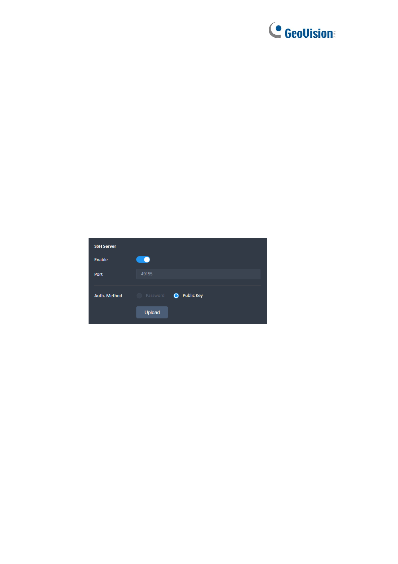
5. SSH Server
⚫ The SSH default is enabled, the default account is root and password is the
same as default administrator. ( See section 2.1 for Default User Name &
Password )
⚫ Port: The Internet Assigned Numbers Authority (IANA) suggests the range
49152 to 65535 (215+214 to 216−1) for dynamic or private ports (Please refer
to https://en.wikipedia.org/wiki/Ephemeral_port )
⚫ Modify Password
➢ Click the “Modify” button and a dialog will pop up to change the SSH
password.
➢ Please refer to “Password” for password rules.
➢ All the fields must be filled in.
➢ All the input boxe must be correctly formatted
6. Public Key File
⚫ The public key file size cannot be larger than 512k bytes.
⚫ The filename extension of the file key can only be .pem.
⚫ Even if the public key file is corrupted, it can be uploaded.
⚫ The file will be saved after the upload is complete.
⚫ If camera has no public key, user can only login SSH via password.
⚫ If camera has valid public key.
➢ If password is selected, user can login SSH via password and public key.
➢ If public key is selected, user can only login SSH via public key.
⚫ After public key uploaded, the SSH connection will still fail in the cases below
➢ Camera has corrupted public key file.
➢ Not using paired key to connect to camera.
⚫ Upload the Public Key File
➢ Click [ Upload ] button
➢ Select the file to upload in a “File Open Windows“
◆ The file must be in correct format
51
➢ Upload file
◆ The network must be connected
◆ Click to cancel the action
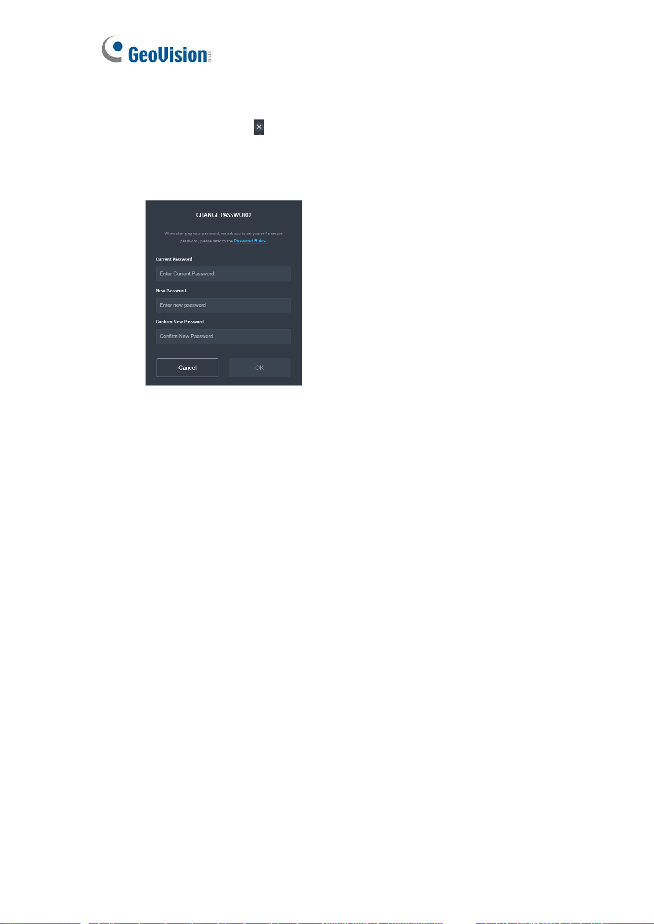
25 Password
1. Change Password
⚫ Key in Current Password
⚫ Key in New Password & Confirm New Password
⚫ Click [ Save or Cancel ] to Leave without saving

52
2. Password Not Match
⚫ When "New Password" and "Confirm New Password" are different, follow the
rule below.
➢ Click "New Password", delete the text in the two tables of "New
Password" and "Confirm New Password”.
➢ Click "Confirm New Password" to delete only the text in the "Confirm
New Password”.
26 Language
You can choose different UI languages.
27 Log Out
⚫ There are 5 ways to log out the Web Viewer:
➢ In Administration Page, click [Reboot] or [Factory Reset] could restart the
camera.
➢ Close the web browser should forcefully logout without displaying any
message.
➢ Power off the computer should forcefully logout without displaying any
message.
➢ In Log Out of alert, click [OK] to enter the Login Screen.
➢ The system will automatically log out after ilde for 10 minutes (600
seconds).