
User Manual
MINI CIRCULAR SAW WITH LASER
Model: TCS115E
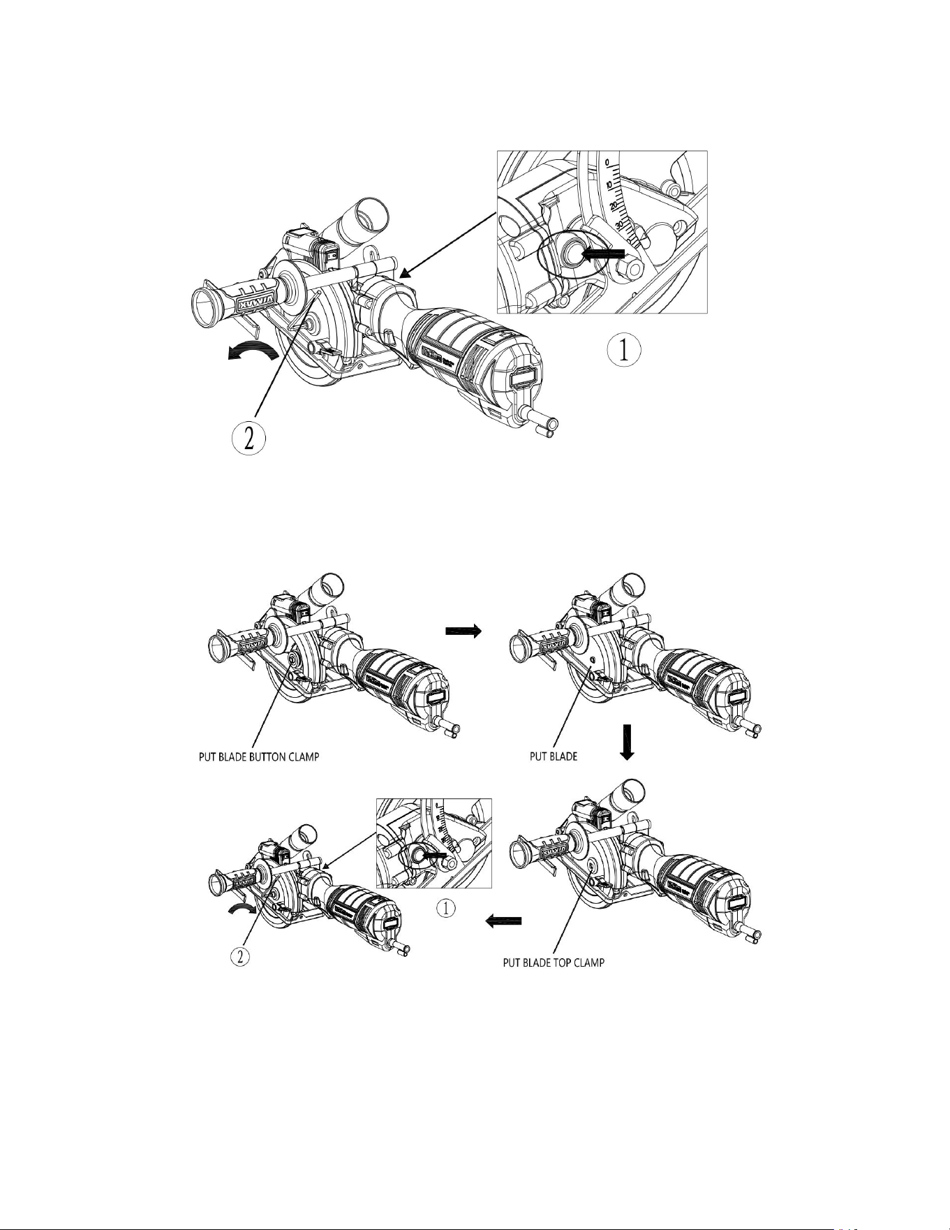
DISASSEMBLE BLADE
1) PRESS LOCK SHAFT BUTTON ;
2) LOOSE SCREW;
ASSEMBLE BLADE
PUT BLADE BUTTOM CLAMP
1) PRESS LOCK SHAFT BUTTON ;
2) WRENCH TIGHTEN SCREW; PUT BLADE TOP CLAMP

PRODUCT SPECIFICATIONS
Rating:
120 V 60 Hz (US) ,220-240V 50Hz(UK) AC
Amperes:
6.2 A (US) / 750W (UK)
Speed:
3,500 RPM (no load) Max.
Blade:
5”(125 mm) 24TCT
Arbor:
3/8" (9.5 mm)
Depth of cut @ 90°:
1-7/8" (47.6 mm)
Depth of cut @ 45°:
1-1/4" (31.8 mm)
Technical questions
Replacement parts
Parts missing from package
GENERAL SAFETY WARNINGS
A WARNING: Before using this tool or any of its accessories, read this manual and
follow all Safety Rules and Operating Instructions. The important precautions,
safeguards and instructions appearing in this manual are not meant to cover all
possible situations. It must be understood that common sense and caution are
factors which cannot be built into the product.
This instruction manual includes the following:
General Safety Rules
Specific Safety Rules and Symbols
Functional Description
Assembly
Operation
Maintenance
Accessories
EYE, EAR & LUNG PROTECTION
ALWAYS WEAR EYE PROTECTION THAT CONFORMS WITH CSA
REQUIREMENTS or ANSI SAFETY STANDARD Z87.1
FLYING DEBRIS can cause permanent eye damage. Prescription eyeglasses ARE NOT
a replacement for proper eye protection.
WARNING: Non-compliant eyewear can cause serious injury if broken during
the operation of a power tool.
WARNING: Use hearing protection, particularly during extended periods of
operation of the tool, or if the operation is noisy.
GENERAL SAFETY WARNINGS
WEAR A DUST MASK THAT IS DESIGNED TO BE USED WHENOPERATING A
POWER TOOL IN A DUSTY ENVIRONMENT.
WARNING: Dust that is created by power sanding, sawing, grinding, drilling,
and other construction activities may contain chemicals that are known to cause
cancer, birth defects, or other genetic abnormalities. These chemicals include:
Lead from lead-based paints Crystalline silica from bricks, cement, and other
masonry products Arsenic and chromium from chemically treated lumber
The level of risk from exposure to these chemicals varies, according to how often
this type of work is performed. In order to reduce exposure to these chemicals, work
in a well-ventilated area, and use approved safety equipment, such as a dust mask
that is specifically designed to filter out microscopic particles.
ELECTRICAL SAFETY
WARNING: To avoid electrical hazards, fire hazards or damage to the tool, use
proper circuit protection.
This tool is wired at the factory for 120V AC operation. It must be connected to a
120V AC, 15 AMP circuit that is protected by a time-delayed fuse or circuit breaker.
To avoid shock or fire, replace power cord immediately if it is worn, cut or damaged
in any way.
POWER TOOL SAFETY
WARNING: Read all safety warnings and instructions. Failure to follow the
warnings and instructions may result in electric shock, fire and/or serious injury.

Save all warnings and instructions for future reference.
Work area safety
1. Keep work area clean and well lit. Cluttered or dark areas invite accidents.
2. Do not operate power tools in explosive atmospheres, such as in the presence of
flammable liquids, gases or dust. Power tools create sparks which may ignite the
dust or fumes.
3. Keep children and bystanders away while operating a power tool. Distractions
can cause you to lose control.
Electrical safety
Power tool plugs must match the outlet. Never modify the plug in any way. Do not
use any adapter plugs with earthed (grounded) power tools. Unmodified plugs and
matching outlets will reduce risk of electric shock.
Avoid body contact with earthed or grounded surfaces such as pipes, radiators,
ranges and refrigerators. There is an increased risk of electric shock if your body is
earthed or grounded.
Do not expose power tools to rain or wet conditions. Water entering a power
tool will increase the risk of electric shock.
Do not abuse the cord. Never use the cord for carrying, pulling or unplug- ging the
power tool. Keep cord away from heat, oil, sharp edges or moving parts. Damaged or
entangled cords increase the risk of electric shock.
When operating a power tool outdoors, use an extension cord suitable for outdoor
use. Use of a cord suitable for outdoor use reduces the risk of electric shock.
If operating a power tool in a damp location is unavoidable, use a residual current
device (RCD) protected supply. Use of a ground fault circuit interrupter (GFCl)
reduces the risk of electric shock.
Personal safety
Stay alert, watch what you are doing and use common sense when operat- ing a
power tool. Do not use a power tool while you are tired or under the influence of
drugs, alcohol or medication. A moment of inattention while operating power tools
may result in serious personal injury.
Use personal protective equipment. Always wear eye protection. Protective
equipment such as dust mask, non-skid safety shoes, hard hat, or hearing protection
used for appropriate conditions will reduce personal injuries.
Prevent unintentional starting. Ensure the switch is in the off-position

before connecting to power source and/or battery pack, picking up or carrying the
tool.Carrying power tools with your finger on the switch or energiz- ing power tools
that have the switch on invites accidents.
Remove any adjusting key or wrench before turning the power tool on. A wrench or
a key left attached to a rotating part of the power tool may result in personal injury.
Do not overreach. Keep proper footing and balance at all times. This enables better
control of the power tool in unexpected situations.
Dress properly. Do not wear loose clothing or jewelry. Keep your hair, clothing and
gloves away from moving parts. Loose clothes, jewelry or long hair can be caught in
moving parts.
If devices are provided for the connection of dust extraction and collection facilities,
ensure these are connected and properly used. Use of dust collection can reduce
dust- related hazards
POWER TOOL SAFETY
Power tool use and care
Do not force the power tool. Use the correct power tool for your application. The
correct power tool will do the job better and safer at the rate for which it was
designed.
Do not use the power tool if the switch does not turn it on and off. Any power tool
that cannot be controlled with the switch is dangerous and must be repaired.
Disconnect the plug from the power source and/or the battery pack from the power
tool before making any adjustments, changing accessories, or storing power tools.
Such preventive safety measures reduce the risk of starting the power tool
accidentally.
Store idle power tools out of the reach of children and do not allow persons
unfamiliar with the power tool or these instructions to operate the power tool.
Power tools are dangerous in the hands of untrained users.
Maintain power tools. Check for misalignment or binding of moving parts, breakage
of parts and any other condition that may affect the power tool’s operation. If
damaged, have the power tool repaired before use. Many accidents are caused by
poorly maintained power tools.
Keep cutting tools sharp and clean. Properly maintained cutting tools with sharp
cutting edges are less likely to bind and are easier to control.
Use the power tool, accessories and tool bits etc. in accordance with these
instructions, taking into account the working conditions and the work to be
performed. Use of the power tool for operations different from those intended could
result in a hazardous situation.

Use clamps or another practical way to secure and support the workpiece to a stable
platform. Holding the work by hand or against your body leaves it unstable and may
lead to loss of control.
Service
Have your power tool serviced by a qualified repair person using only identical
replacement parts. This will ensure that the safety of the power tool is maintained.
SAVE THESE INSTRUCTIONS FOR REFERENCE
SPECIFIC SAFETY RULES
WARNING: Know your circular saw. Do not plug the tool into the power
source until you have read and understand this Instruction Manual. Learn the tool’s
applications and limitations, as well as the specific potential hazards related to this
tool. Following this rule will reduce the risk of electric shock, fire, or serious injury.
Always wear eye protection. Any power tool can throw foreign objects into your
eyes and cause permanent eye damage.
ALWAYS wear safety goggles (not glasses) that comply with ANSI safety standard
287.1.
Everyday glasses have only impact resistant lenses. They ARE NOT safety glasses.
Always wear eye protection. Any power tool can throw foreign objects
settes into your eyes and cause permanent eye damage.
ALWAYS wear safety goggles (not glasses) that comply with ANSI safety
standard Z87.1.
Everyday glasses have only impact resistant lenses. They ARE NOT safety glasses.
WARNING: Glasses or goggles not in compliance with ANSI Z87.1 could
cause serious injury when they break. Always keep hands out of the path of the saw
blade. Avoid awkward hand
positions where a sudden slip could cause your hand to move into the path of the
saw blade.
DANGER: Keep hands away from cutting area and the blade. Keep your second
hand on the tool. If both hands are holding the saw, they cannot be cut by the blade.
Do not reach underneath the workpiece. The guard cannot protect you from the
blade below the workpiece.

Adjust the cutting depth to the thickness of the workpiece. Less than a full tooth of
the blade teeth should be visible below the workpiece.
Never hold piece being cut in your hands or across your leg. Secure the workpiece to
a stable platform. It is important to support the work properly to minimize body
exposure, blade binding, or loss of control.
Hold power tool by insulated gripping surfaces when performing an operation
where the cutting tool may contact hidden wiring or its own cord. Contact with a
"live" wire will also make exposed metal parts of the power tool "live" and shock the
operator.
When ripping always use the rip fence or straight edge guide. This improves the
accuracy of cut and reduces the chance of the blade binding.
Always use blades with correct size and shape (diamond versus round) of arbor
holes. Blades that do not match the mounting hardware of the saw will run
eccentrically, causing loss of control.
Never use damaged or incorrect blade washers or bolt. The blade washers and bolt
were specially designed for your saw, for optimum performance and safety of
operation.
Never use abrasive blades with this circular saw.
CAUSES AND OPERATOR PREVENTION OF KICKBACK
Kickback is a sudden reaction to a pinched, bound or misaligned saw blade, causing
an uncontrolled saw to lift up and out of the workpiece toward the operator;
When the blade is pinched or bound tightly by the kerf closing down, the blade stalls
and the motor reaction drives the unit rapidly back toward the operator.
If the blade becomes twisted or misaligned in the cut, the teeth at the back edge of
the blade can dig into the top surface of the wood causing the blade to climb out of
the kerf and jump back toward the operator.
Kickback is the result of saw misuse and/or incorrect operating procedures or
conditions and can be avoided by taking proper precautions as given below:
SPECIFIC SAFETY RULES
CAUSES AND OPERATOR PREVENTION OF KICKBACK -— cont'd
Maintain a firm grip on the saw and position your arms to resist kickback forces.
Position your body to the left or right side of the blade, but not in line with the blade.
Kickback could cause the saw to jump backwards, but kickback forces can be
controlled by the operator, if proper precautions are taken.
When the blade is binding, or when interrupting a cut for any reason, release the
trigger and hold the saw motionless in the material until the blade comes to a

complete stop. Never attempt to remove the saw from the work or pull the saw
backward while the blade is in motion or kickback may occur. Investigate and take
corrective actions to eliminate the cause of blade binding.
When restarting a saw in the workpiece, center the saw blade in the kerf and check
that saw teeth are not engaged into the material. If the saw blades are binding, it
may walk up or kickback from the workpiece as the saw is restarted.
Support large panels to minimize the risk of blade pinching and kickback. Large
panels tend to sag under their own weight. Supports must be placed under the panel
on both sides, near the line of cut and near the edge of the panel.
Do not use dull or damaged blades. Unsharpened or improperly set blades produce
narrow kerf causing excessive friction, blade binding and kickback. Do not use dull
or damaged blades. Unsharpened or improperly set blades produce narrow kerf
causing excessive friction, blade binding and kickback. Blade depth and bevel
adjusting locking levers must be tight and secure before making cut. If blade
adjustment shifts while cutting, it may cause binding and kickback.
Use extra caution when making a “plunge cut" into existing walls or other blind
areas. The protruding blade may cut objects that can cause kickback.
ADDITIONAL SPECIFIC SAFETY RULES
Check the lower guard for proper closing before each use. Do not operate the saw if
the lower guard does not move freely and close instantly. Never clamp or tie the
lower guard into the open position. If the saw is accidentally dropped, the lower
guard may be damaged. Raise the lower guard with the retracting handle and make
sure it moves freely and does not touch the blade or any other part in all depths of
cuts.
Check the operation of the lower guard spring. If the guard and the spring are not
operating properly, they must be serviced before use. The lower guard may operate
sluggishly due to damaged parts, gummy deposits, or a build-up of debris.
The lower guard should be retracted manually only for special cuts such as “plunge
cuts" and "compound cuts". Raise lower guard by retracting handle and as soon as
the blade enters the material, the lower guard must be released. For all other sawing,
the lower guard should operate automatically.
Always observe that the lower guard is covering the blade before placing saw down
on bench or floor. An unprotected, coasting blade will cause the saw to walk
backwards, cutting whatever is in its path. Be aware of the time it takes for the blade
to stop after the switch is released.
Never operate the saw while it is being carried to another location. The blade guard
may be open and potentially cause serious injury.
If the switch fails to turn the saw ON or OFF properly, stop using it immediately and
have the saw switch repaired.

Always allow the saw to reach full speed before beginning the cut.
SPECIFIC SAFETY RULES ADDITIONAL SPECIFIC SAFETY RULES - cont’d
Never use the side of the blade for cutting. When making horizontal cuts, make sure
the weight of the tool is not forcing the side of the blade to do the cutting. This will
reduce the risk of kickback.
Make sure there are no nails or foreign objects in the area of the workpiece to be cut.
Never lay workpiece on hard surfaces like concrete, stone, etc. The protrud- ing
blade may cause tool to jump.
DANGER: To avoid injury from accidental starting, always remove the plug from
the power source before making any adjustments and before installing or removing
a saw blade.
When replacing the blade, make sure the replacement blade is 3%" in diameter and
is rated for at least 3,500 RPM. Installing an incorrect blade will result in possible
injury and poor cutting action.
After changing a blade or making adjustments, make sure the blade clamp screw is
securely tightened. Loose blades and adjustment devices will be violently thrown.
Never touch the blade during or immediately after use. After use the blade is too hot
to be safely touched with bare hands.
EXTENSION CORD SAFETY
WARNING: Keep the extension cord clear of the working area. Position the cord so it
will not get caught on the workpiece, tools or any other obstructions while you are
working with the power tool.
Make sure any extension cord used with this tool is in good condition. When using
an extension cord, be sure to use one of heavy enough gauge to carry the current the
tool will draw. An undersized cord will cause a drop in line voltage resulting in loss
of power and overheating.
The table at right shows the correct size to use according to cord length and
nameplate ampere rating. If in doubt, use the next heavier gauge. The smaller the
gauge number the heavier the cord.
Be sure your extension cord is properly wired and in good condition. Always replace
a damaged extension cord or have it repaired by a qualified electrician before using
it. Protect your extension cord from sharp objects, excessive heat and damp or wet
areas.
Use a separate electrical circuit for your power tools. This circuit must not be less
than 14 gauge wire and should be protected with either a 15 AMP time delayed fuse
or circuit breaker. Before connecting the power tool to the power source, make sure

the switch is in the OFF position and the power source is the same as indicated on
the nameplate. Running at lower voltage will damage the motor.
WARNING: Repair or replace damaged or worn extension cords immedi- ately.
Select the appropriate extension cord gauge and length using the chart below.
When operating a power tool outdoors, use an outdoor extension cord marked "W-
A" or "W". These cords are rated for outdoor use and reduce the risk of electric
shock.
WARNING: Keep the extension cord clear of the working area. Position the cord so it
will not get caught on the workpiece, tools or any other obstructions while you are
working with the power tool.
MINIMUM GAUGE (AWG) EXTENSION CORDS (120V use only)
Amperage rating
Total length
More than
Not more than
25’(7.5M)
50’(15M)
100’(30M)
150’(45M)
0
6
18
16
16
14
6
10
18
16
14
12
10
12
16
16
14
12
12
16
14
12
Not Applicable
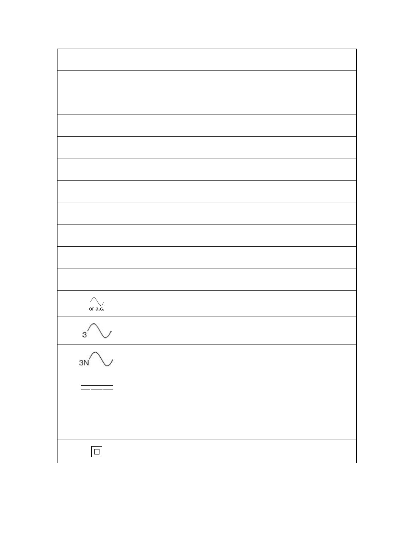
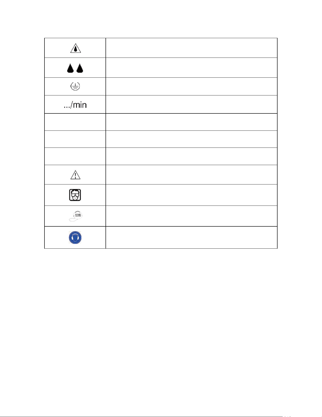
SYMBOLS
WARNING: Some of the following symbols may appear on the circular saw.
Study these symbols and learn their meaning. Proper interpretation of these
symbols will allow for more efficient and safer operation of this tool.
V
Volts
A
Amperes
Hz
Herts
W
Watts
KW
Kilowatts
µF
Microfarads
L
Liters
Kg
Kilograms
H
Hours
N/cm²
Newtons per square centimeter
Pa
Pascals
OPM
Oscillations per minute
Min
Minutes
S
Seconds
Alternating current
Three-phase alternating current
Three-phase alternating current with neutral
Direct current
n₀
No load speed
≂
Alternating or direct current
Class II construction
Splash-proof construction
Watertight construction
Protective grounding at grounding terminal, Class I tools
Revolutions or reciprocations per minute
∅
Diameter
0
Off position
→
Arrow
Warning symbol
Wear your safety glasses
Wear a dust mask
Wear hearing protection
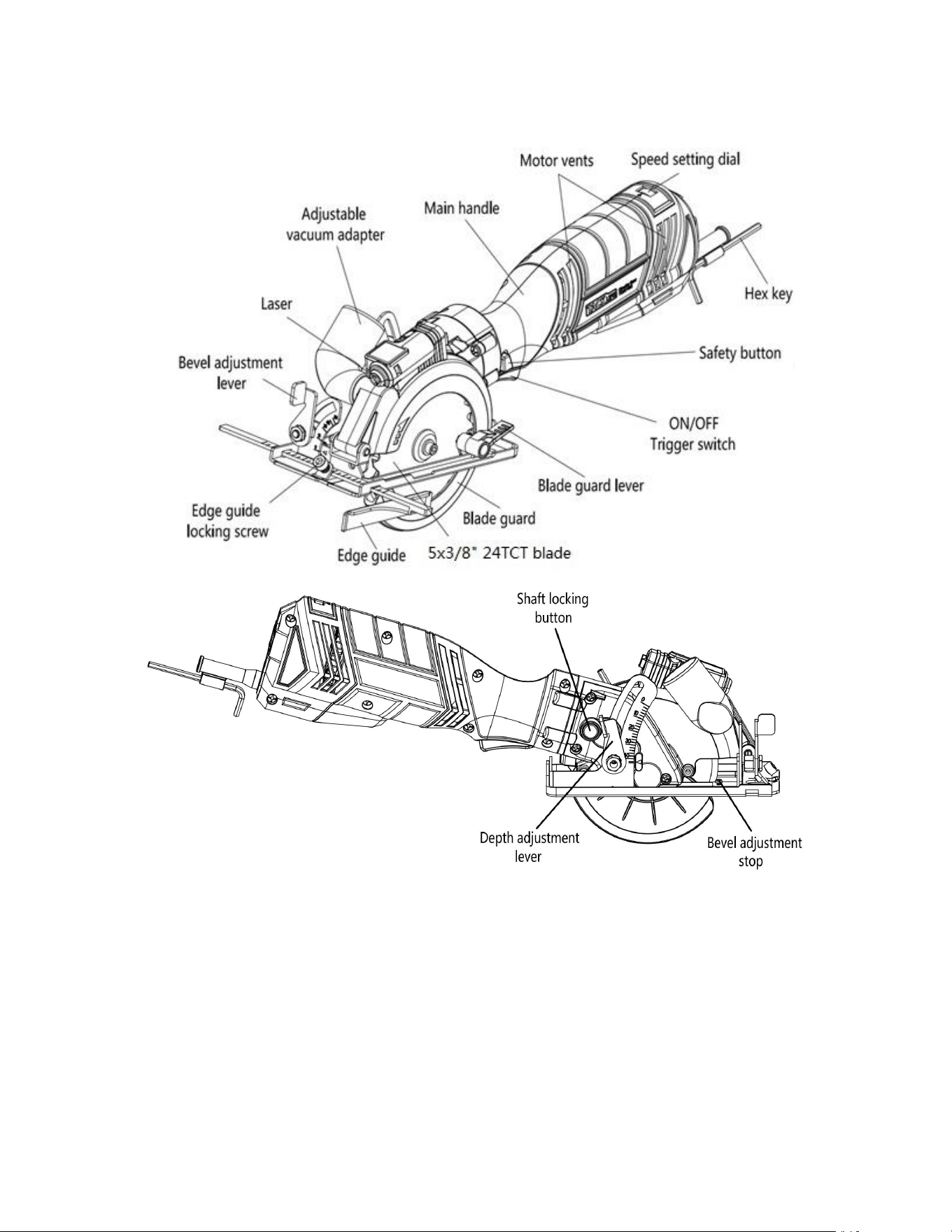
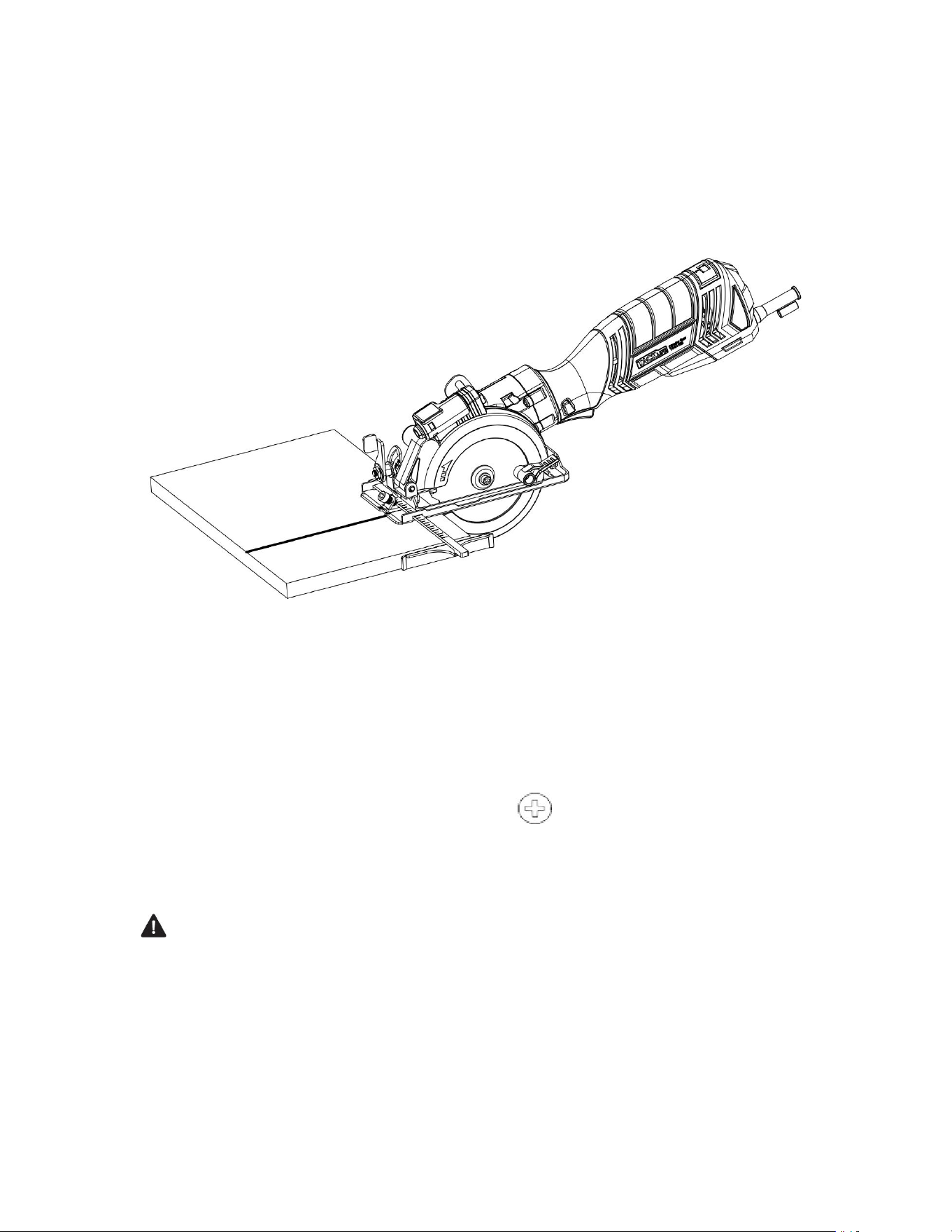
KNOW YOUR CIRCULAR SAW
ASSEMBLY AND OPERATING
NOTE: For illustrative purposes, some drawings show the vacuum adaptor installed
on the saw. The vacuum adaptor does NOT have to be installed if a vacuum is not
being used.
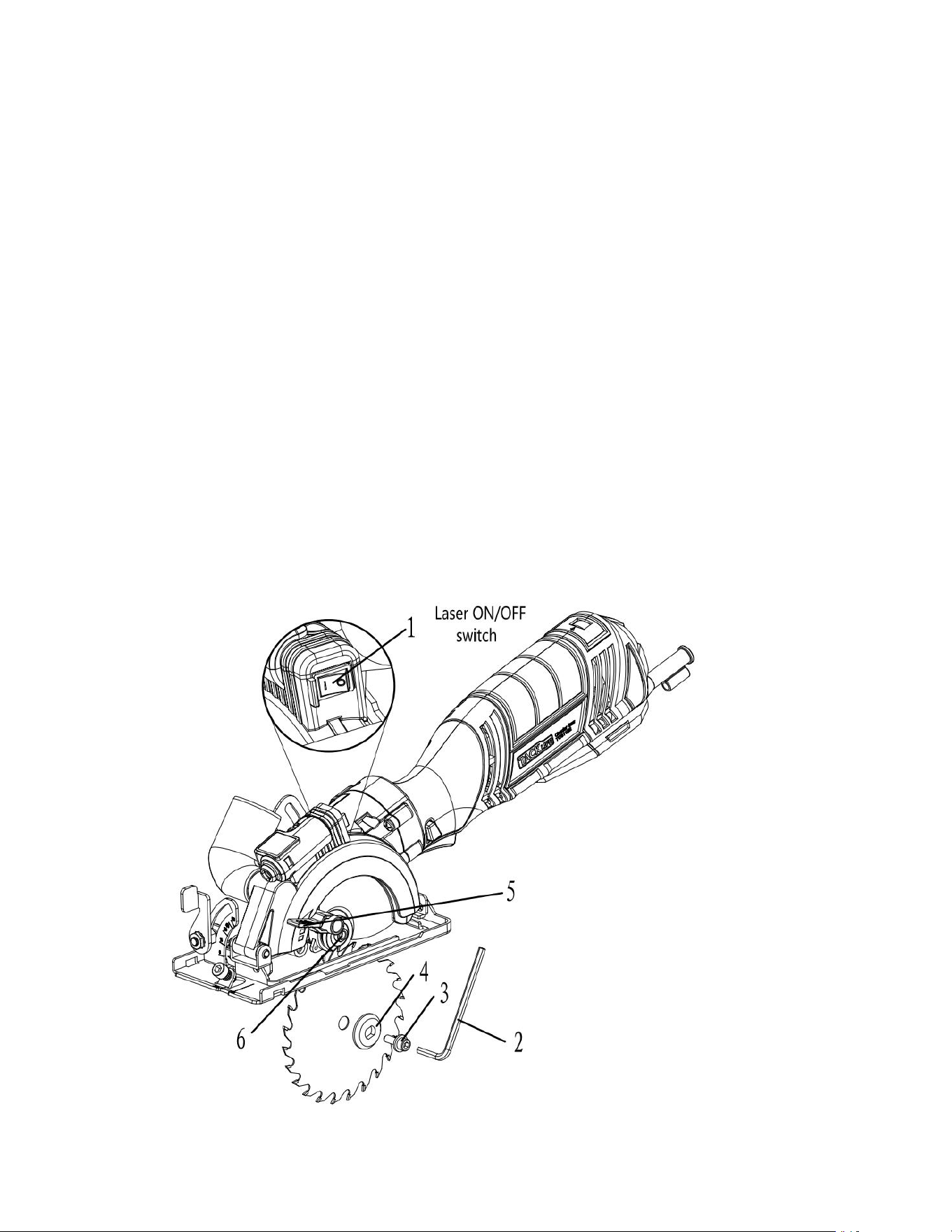
REMOVING AND INSTALLING A BLADE
WARNING: Always remove the plug from the power source before removing the
blade or adjusting the saw in any way.
WARNING: Use caution when handling the blade. It is sharp and can easily cut your
hand.
1. Press inward on the shaft locking button (1) (Fig. 1).
2. Insert the 5mm hex key (2) into the blade screw (3). While pressing inward on the
shaft locking button, rotate the hex key clockwise until the shaft locking button
engages with the blade shaft. Continue turning the hex key clockwise and remove
the blade screw and the outer blade flange (4).
NOTE: The blade screw is a left hand thread.
3. Rotate the blade guard lever (5) counter clockwise as far as it will go.
4. If there is already a blade installed on the saw, lift the blade off the spindle (6) and
slide it out through the slot in the sole plate.
Laser ON/OFF switch
5. To reinstall a blade, reverse the above procedure.
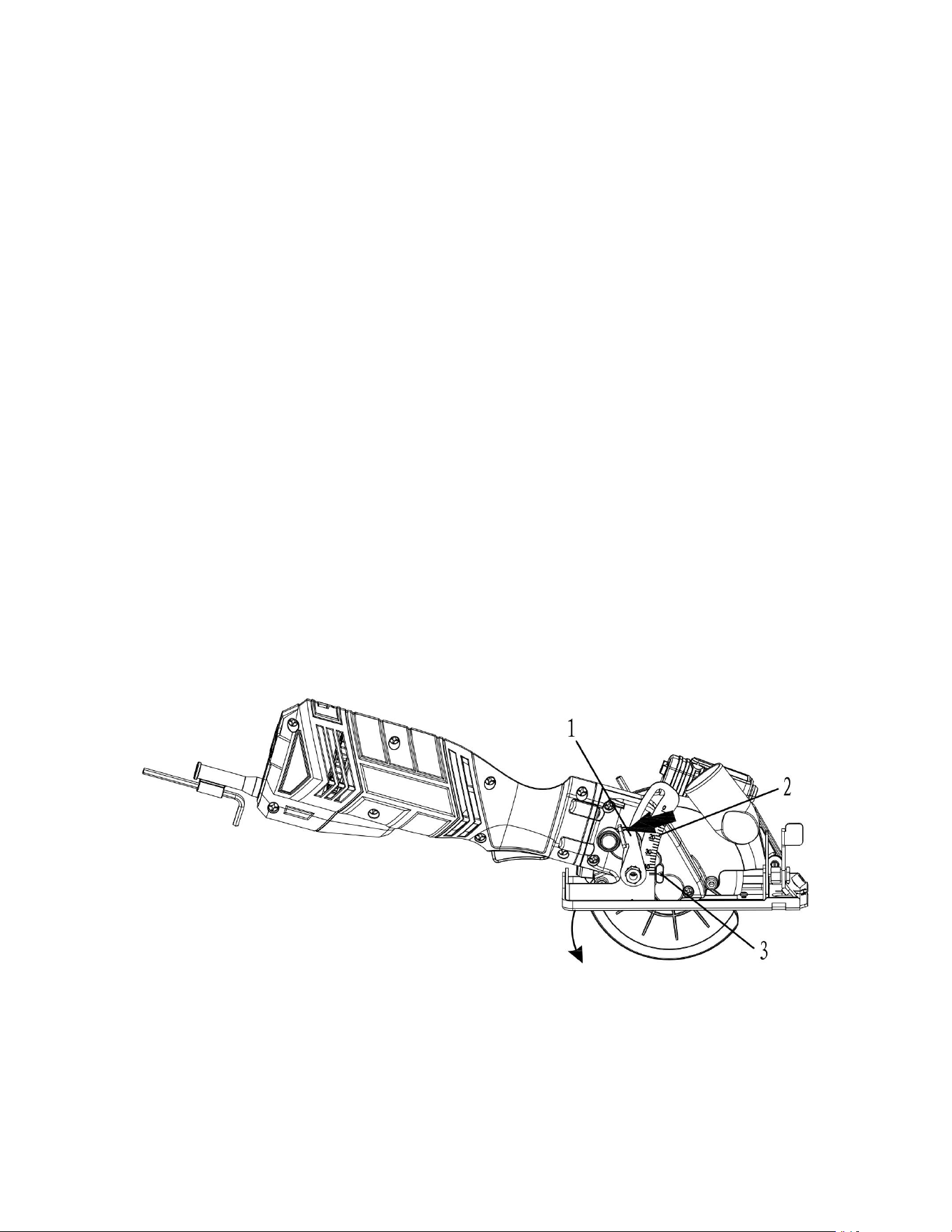
Fig.1
NOTES:
a)Make sure the blade teeth are pointing forward at the bottom of the blade.
b)When re-installing the outer flange nut make sure the flats of the flange nut fit
over the flats on the spindle.
c)Turn the blade screw counter clockwise to thread it into the spindle. Make sure
the screw is not cross threaded.
6. When the new blade, outer flange and blade screw are in place, press the spindle
locking button and fully tighten the blade screw.
7. When the blade screw is fully tightened, carefully rotate the blade to ensure it
does not wobble. If it wobbles, remove and reinstall the blade making sure it is
installed correctly.
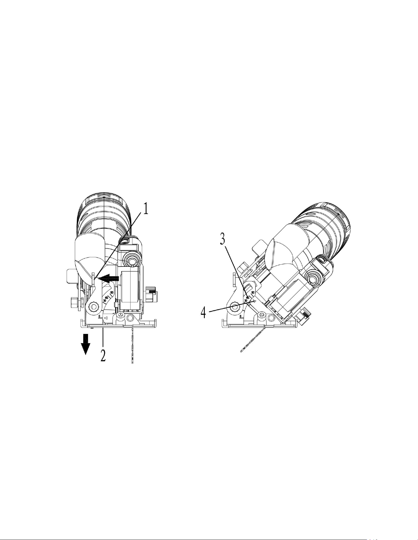
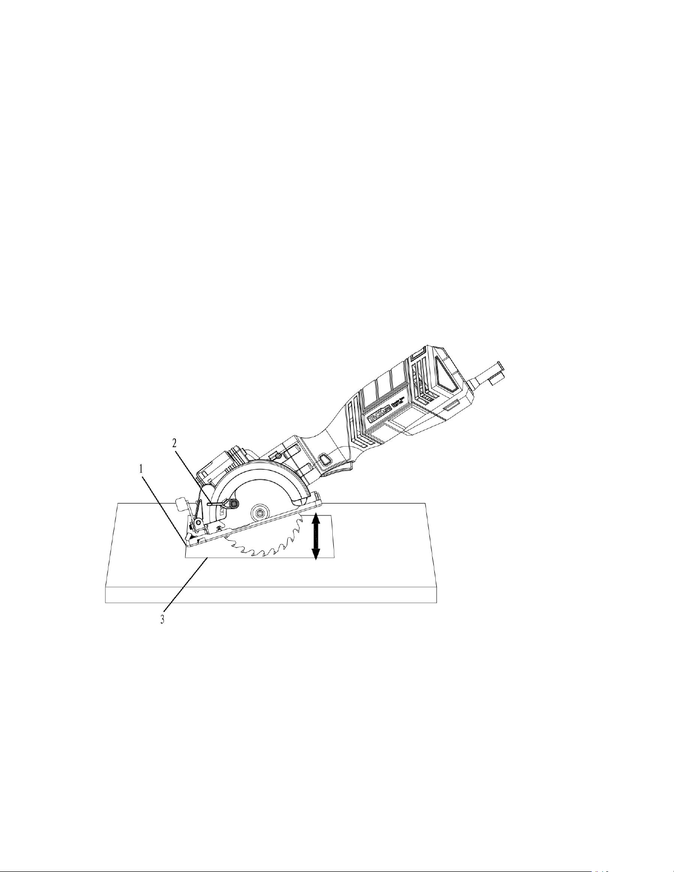
SETTING THE CUTTING DEPTH
The cutting depth of the blade should be set to suit the thickness of the material
being cut. The cutting depth should be approximately 1/8"
(3 mm) greater than the thickness of the material being cut.
1.Rotate the cutting depth locking lever (1) counter clockwise (Fig. 2). 2.Lower the
sole plate to the desired depth. NOTE: Align the desired depth on the depth control
scale (2) with the alignment mark (3) on the saw housing.
Fig. 2
ASSEMBLY AND OPERATING
SETTING THE BEVEL CUTTING ANGLE
The sole plate can be set to perform bevel cuts up to 45°. 1. Rotate the bevel angle
locking lever (1) counter clockwise (Fig. 3). 2. Rotate the sole plate (2) to the desired
angle.
NOTES:
a)Align the desired angle on the bevel scale
(3)with the alignment mark (4) on the sole plate housing.
b)Always make a test cut on a scrap workpiece and check to make sure the bevel cut
is correct.
Fig,3
SETTING THE "ZERO" BEVEL ANGLE FOR ACCURATE 90° CUTTING Before making
any cuts, it is important to make a test cut on a scrap workpiece and adjust the bevel
angle stop if necessary to ensure that the "Zero" bevel
adjustment provides accurate 90° cuts.
1. Loosen the bevel locking lever (1) and rotate the sole plate toward the 0° mark as
far as it will go and tighten the bevel angle locking lever (Fig 4).
2. Make a test cut on a scrap workpiece and check the cut with a carpenters’ square
to verify that the saw is cutting at 90°.
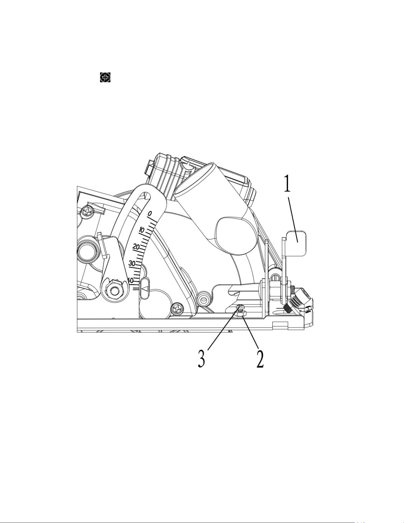
3. If the test cut is not at 90°, turn the zero adjustment lock nut (2) counter
clockwise approximately % turn using a 7mm wrench.
4. Use a #2 screwdriver to turn the zero bevel adjusting screw (3) in or out
until the saw is cutting at 90° when the sole plate is contacting the adjusting screw.
5. Tighten the lock nut while using the screwdriver to prevent the adjusting screw
from turning.
NOTE: When the final adjustment is made and the locknut tightened, recheck the
cutting angle on a scrap workpiece.
Fig.4
INSTALLING THE EDGE GUIDE
The edge guide can be used to facilitate accurate cutting when ripping pieces up to
5" wide.
1. Loosen the edge guide locking screw (1) counter clockwise approximately 2 turns
using the 5mm hex key (Fig. 5).
2. Slide the edge guide mounting rod (2) into the mounting slots (3) in the sole plate.
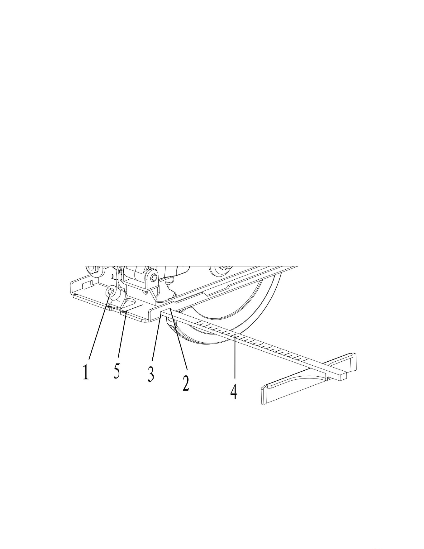
3. Align the desired cutting width on the scale
(4)with the 0° cutting mark (5) in the sole plate.
4. Tighten the edge guide locking screw to lock the edge guide into position.
NOTE: Do not over tighten as you may strip the threads.
5. Make a test cut on a scrap workpiece to verify the edge guide setting. Adjust as
necessary.
Correct selection of cutting speed
This machine has 6 speed control discs, from 1 to 6, the speed is increased in turn.
The cutting speed can be selected depending on the material to be cut. In general,
the higher the hardness of the material, the lower the cutting speed, which can
protect the machine and the saw blade, greatly improving the service life of the
machine and the saw blade.
Warning: When setting speed, the machine must stop running.
ASSEMBLY AND OPERATING
INSTALLING THE VACUUM GUIDE - cont’d
Fig. 5
INSTALLING THE VACUUM ADAPTER A workshop vacuum can be attached to the
circular saw to collect much of the dust created from cutting.
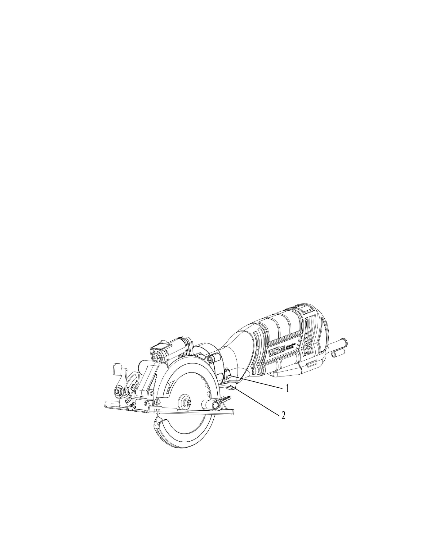
1. Place the small end of the vacuum adaptor (1)over the vacuum port (2) on the
blade housing (Fig. 6).
NOTE: Rotate the adaptor slightly while pushing it onto the vacuum port.
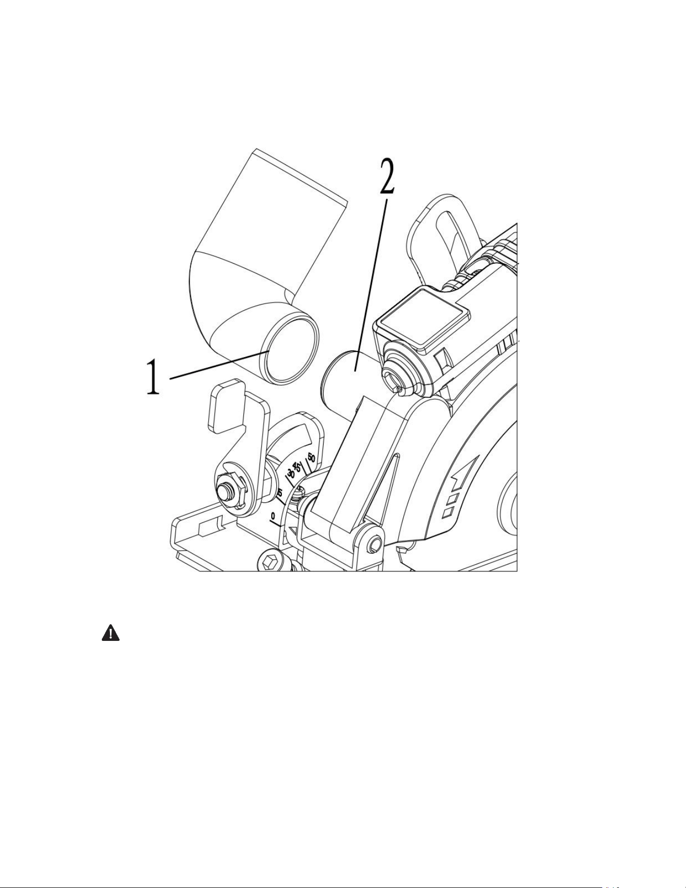
2. Attach a standard workshop vacuum to the large end of the adaptor. NOTE: Not all
of the cutting dust will be captured by the vacuum as some will be thrown beyond
the vacuum range.
Fig.6
WARNING:
For safety reasons, the operator must read the sections of this Owner’s Manual
entitled "GENERAL SAFETY WARNINGS", "POWER TOOL SAFETY", "SPECIFIC
SAFETY RULES", "EXTENSION CORD SAFETY" and "SYMBOLS" before using this
circular saw.
Verify the following every time the circular saw is used:
1. Correct blade is installed for the material being cut.
2. Blade is in good condition and is properly installed.
3. Blade guard is in place and is in good working order.
4. Workpiece is properly secured.
5. Safety glasses, dust mask and hearing protection are being worn.
Failure to observe these safety rules will significantly increase the risk of injury.
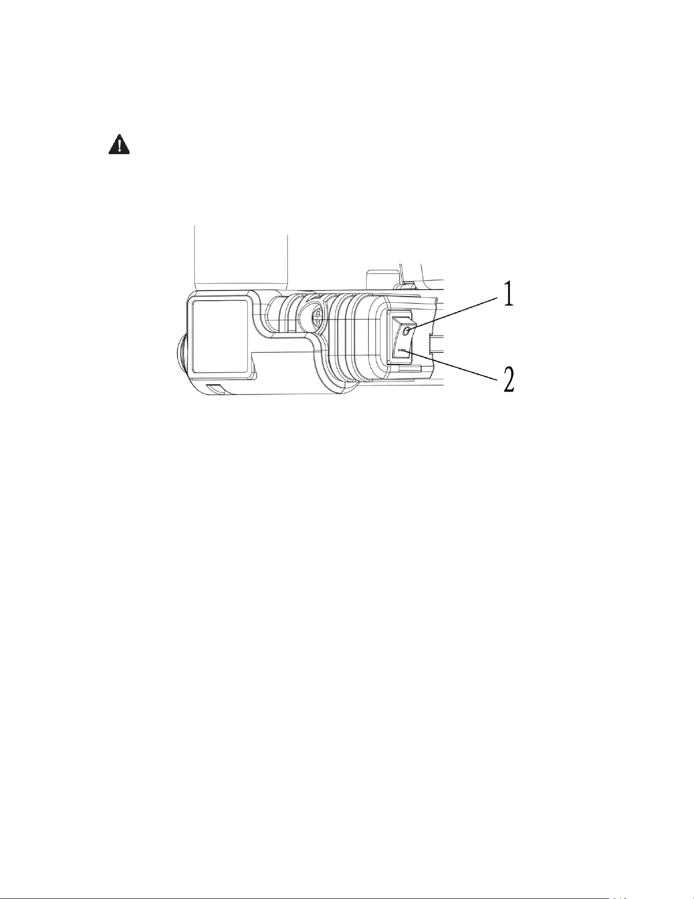
LOCK-OFF BUTTON AND TRIGGER SWITCH
The lock-off button (1) is a safety device designed to reduce the possibility of
accidentally starting the saw (Fig. 7). This button must be depressed before the
trigger switch (2) can be depressed.
1. To turn the saw ON, depress the lock-off button with your thumb.
2. While holding the lock-off button in the depressed position, squeeze the trigger
switch to start the saw.
3. Once the saw starts, release the lock-off button. The saw will remain running until
the trigger switch is released.
4. To turn the saw OFF, release the trigger switch.
NOTE: The lock-off button must be depressed again to restart the saw.
ASSEMBLY AND OPERATING
LOCK-OFF BUTTON AND TRIGGER SWITCH - cont’d
Fig.7
LASER ON/OFF SWITCH
This saw is equipped with a laser guidance system for more precise cutting.
DANGER: Never allow the laser beam to shine into a person’s eyes. Serious eye
damage could result.
To turn the laser ON, press the left side of the laser switch (1) (Fig. 8). To turn the
laser OFF, press the right side of the laser switch.
Fig.8
MATERIALS YOU CAN CUT
The circular saw is a versatile saw that allows you to cut many different types of
materials. Some of the materials include:
• Wood products such as lumber, hardwood, plywood, composition
board and paneling
• Masonite and plastic
NOTE: There are several different types of blades available. Generally, blades with
carbide- tipped teeth cut better and stay sharp longer.
Tooth count and configuration are also important. High tooth counts cut slower
and are best suited for making smooth cuts on thinner materials such as paneling.
Use the correct blade for your application.
GENERAL CUTTING NOTE: Always make a test cut on a scrap workpiece to verify
that all settings are correct.
1. Make any adjustments to the saw before plugging it into the power source.
Adjustments include cutting depth, bevel cutting angle and edge guide (if installed).
2. Clearly mark the workpiece to locate the position of the cut.
3. Hold a smaller workpiece with a vise. Clamp a larger workpiece to a work bench
or table.
DANGER: Any workpiece that is not adequately clamped in place or properly
supported for cutting may come loose or jamb the blade, causing serious injury.
Never hold the workpiece in your hand.
4. Make sure there are no nails, screws, clamps or foreign materials in the path of
the saw blade.
5. Turn the laser ON.
6. Place the front edge of the sole plate on the workpiece.
7.While firmly gripping the saw, and with the blade NOT in contact with the surface
to be cut, start the saw by depressing the lock-off button and then the trigger switch.
8. Once the saw has reached full speed, gradually bring the moving blade into
contact with the workpiece at the appropriate location.
NOTE: To align the saw blade with the cutting mark, use the guide marks on the
front of the sole plate (Fig. 9). Use the 0° cutting mark (1) and the laser line (2) for
right angle cuts. Use the 45° mark (3) for 45° bevel cuts. The 45° mark will allow for
the extra material needed for the angle cut. Always make a test cut on a scrap
workpiece before cutting the new material.
ASSEMBLY AND OPERATING GENERAL CUTTING - cont'd
WARNING: Do not force the circular saw. Use only enough force to keep the
blade cutting at full speed. Excessive pressure on the blade will cause it to slow
down and overheat, resulting in poor cut quality and damage to the motor.
9. Turn laser OFF.
Fig.9
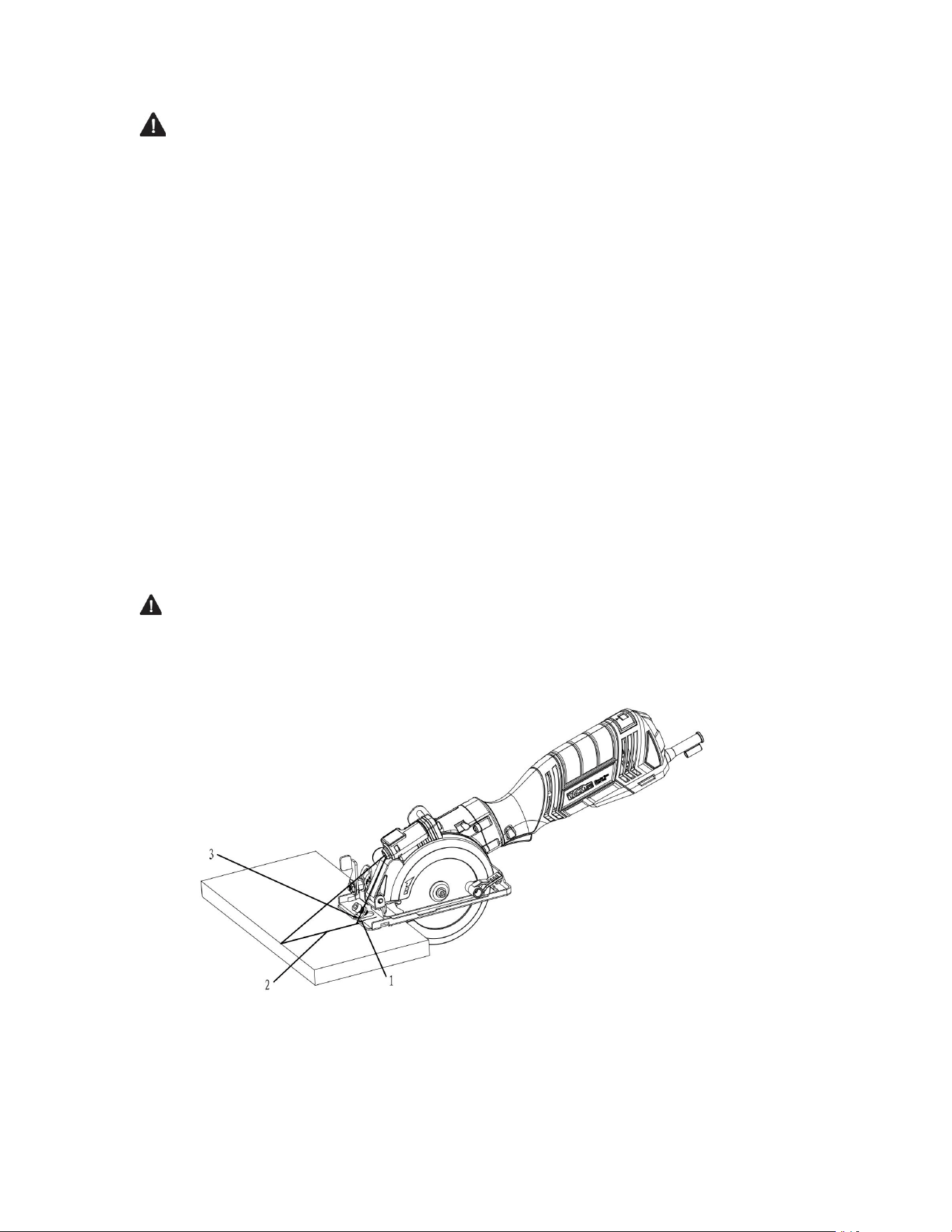
PLUNGE CUTTING
WARNING: To avoid loss of control, damage to the blade or damage to the
workpiece, always use extreme caution when making plunge cuts. It is not
recommended to plunge cut any material other than wood.
1. To plunge cut inside the edges of a workpiece, clearly mark the cutting line on the
workpiece.
2. Set the depth (Fig. 2) and set the bevel angle at 0° (Fig. 3).
3. Set the saw on the workpiece so the front edge of the sole plate (1) is flat on the
workpiece (Fig. 10).
4. Open the blade guard by rotating the blade guard lever (2) forward.
5. Align the saw blade with the cutting line (3) using the 0° cutting mark on the sole
plate and the laser line.
NOTE: Make sure the saw blade is inside the area to be cut out.
Fig. 10
6.Start the saw and slowly lower the blade onto the workpiece while holding the
blade guard lever forward to allow the blade to cut into the workpiece.
7.Continue lowering the blade into the workpiece until the full cutting depth has
been achieved. Continue sawing and complete the cut as required.
CUTTING USING THE EDGE GUIDE
Whenever possible, install the edge guide on the left hand side of the sole plate (Fig.
11). This will place the majority of the tool weight on the larger portion of
the workpiece, making it easier to control the tool. If necessary, the edge guide may
be installed from the opposite side, but the edge guide mounting rod MUST engage
both of the edge guide slots in the sole plate.
Fig.11
ASSEMBLY AND OPERATING CHANGING THE LASER BATTERIES
The batteries that operate the laser will have to be replaced after considerable use
of the laser.
1.Turn the laser switch OFF.
2.Remove the laser cover screw (1) using a #2 screwdriver (Fig. 12).
3.Lift the laser cover (2) off the top of the laser assembly (Fig. 13).
4.Remove the two old batteries (3).
DANGER: Never allow the laser beam to shine into a person’s eyes. Serious eye
damage could result. Make sure the laser switch is OFF and the laser is NOT pointing
toward you while replacing the laser batteries and when checking the laser function.
5.Insert two new batteries.
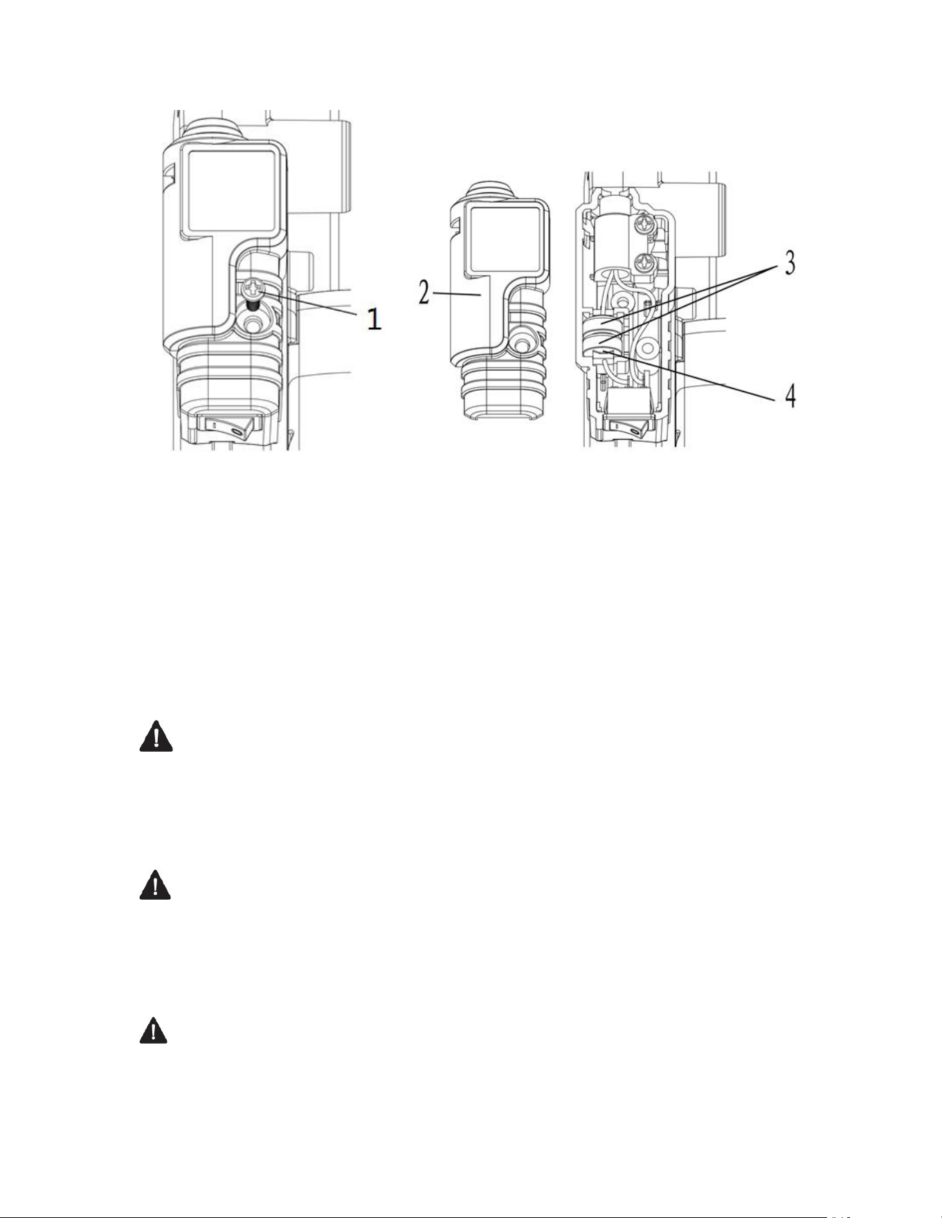
Fig. 12 Fig.13
NOTES:
a)Use two 1.5V LR 44 batteries
b)Install the batteries with the "+" side (4) of the batteries facing the rear of the tool.
6.Re-install the laser cover and fasten it in place with the laser cover screw.
GENERAL
WARNING: When servicing, use only identical replacement parts. The use of
any other part may create a hazard or cause product damage.
DO NOT use solvents when cleaning plastic parts. Plastics are susceptible to damage
from various types of commercial solvents and may be damaged by their use. Use a
clean cloth to remove dirt, dust, oil, grease etc.
WARNING: Do not allow brake fluids, gasoline, petroleum-based products,
penetrating oils, etc. to come into contact with plastic parts. They contain chemicals
that can damage, weaken or destroy plastic.
DO NOT abuse power tools. Abusive practices can damage the tool and the
workpiece.
WARNING: DO NOT attempt to modify tools or create accessories. Any such
alteration or modification is misuse and could result in a hazardous condition
leading to possible serious injury. It will also void the warranty.

It has been found that electric tools are subjected to accelerated wear and possible
premature failure when they are used on fiberglass boats and sports cars, wallboard,
spackling compounds or plaster. The chips and grindings from these materials are
highly abrasive to electric tool parts such as bearings, brushes, commutators, etc.
Consequently, it is not recommended that this tool be used for extended work on
any fiberglass material, wallboard, spackling compounds or plaster.
During any use on these materials it is extremely important that the tool is cleaned
frequently by blowing it out with an air jet.
WARNING: Always wear safety goggles or safety glasses with side shields
during all cutting operations. It is critical that you also wear safety goggles or safety
glasses with side shields and a dust mask while blowing dust out of the circular saw
with an air jet.
Failure to take these safety precautions could result in permanent eye or lung
damage.
LUBRICATION
All of the bearings in this tool are lubricated with a sufficient amount of high-grade
lubricant for the life of the unit under normal conditions.
Therefore, no further lubrication is required.
Shenzhen Take Tools Co., Ltd.
Web: www.tacklifetools.com
Facebook: www.facebook.com/Tacklife.US
E-mail: sup[email protected]
ADD: No.B714,Niulangian Building, Minzhi Road, Longhua District, Shenzhen,
Guangdong, China 518000