Effective: 01-15-2025
Replaces: 11-30-2023
P/N: 100-10000496 Rev. 04
Heat Pump Pool
& Spa Heater
Models: TWPH 4550, 5550, 6550,
6550EHC, 8550, & 8550EHC
FOR YOUR SAFETY: Do not store or use gasoline or other ammable vapors and
liquids or other combustible materials in the vicinity of this or any other appliance.
To do so may result in an explosion or re.
NOTE: The instructions in this manual are for the use of qualied individuals specially trained
and experienced in the installation and maintenance of this type of equipment and related system
components. Installation and service personnel are required by some states to be licensed. Persons
not qualied shall not attempt to install, service, or maintain this equipment.
This manual should be maintained in legible condition and kept adjacent to the heat pump pool heater or in a
safe place for future use.
INSTALLATION AND
OPERATION MANUAL
SCAN WITH QR EQUIPPED SMART
DEVICE FOR ONLINE MANUAL.
NOTICE

2
QUICK START GUIDE
CLEARANCES
Installation Considerations Page 6.
Installation Clearances Page 7.
Hurricane Tie Down Instructions Page 8.
PIPING
Water Connections Page 9.
Flow Rate & Pressure Drop Page 9.
Freeze Protection Page 35.
Plumbing Diagrams Page 39.
WATER CHEMISTRY
Water Chemistry Page 6.
Table A. Water Chemistry Page 6.
POWER
Electrical Connections Page 10.
Table C. Typical System Electrical Power
Requirements Page 10.
CONTROLS INTERFACE
Wiring Diagram -
208V/230V Single-Phase Page 11.
Heater Control Display Page 12.
Program Menu Page 17.
Digital Controls Operation Page 27.
Remote Mode Selector Page 32.
Connect to Wi-Fi with Raymote Page 45.
External Control Outputs Page 73.
Revision 04 reects the following changes:
Updated Figure 2, adding a "rain diverter" and a "rain gutter". Added Figure 8 to show "Ground Lug" on the side of the heater. Revised breaker size callouts
in Table C. Updated Section 12. Program Menu info to reect the correct time to press the keys, as well as Figure 30. Added "Water pressure switch"
and "Water Pressure switch adjustment" information on page 30. Updated Figure 136 with new information regarding "Wiring Valve Actuators". Updated
information regarding "Variable Speed Pump Control Wiring". Updated Figure 140 with information regarding "24VAC Relay Wiring". Updated Table G with
information about "Aquastar VSP". Updated Figure 152 and Figure 153 with information regarding "Pool Light Wiring" and "Air Blower Wiring" accordingly.
Updated Figure 156 regarding "External Device Wiring to Auxiliary Output". Updated Figure 159 regarding "Solar Heater Components in the Piping". Updated
Illustrated Parts List illustration, removing "Control Cover" call out and adding new call outs for "Drain Plug", "Front Cover Panel", and "Badge for Rheem,
Raypak, and Ruud". IPL list updated with info regarding these components.

3
TABLE OF CONTENTS
1. WARNINGS ............................................................. 4
Pay Attention to these Terms ..................................4
2. INTRODUCTION ...................................................... 5
3. WATER CHEMISTRY ............................................... 6
4. INSTALLATION CONSIDERATIONS ...................... 6
5. WATER CONNECTIONS ......................................... 9
6. FLOW RATE & PRESSURE DROP......................... 9
7. ELECTRICAL CONNECTIONS ............................... 9
8. WIRING DIAGRAM ................................................ 11
9. HEATER CONTROL DISPLAY .............................. 12
10. OPERATION MODES ............................................ 12
11. SERVICE MENU ..................................................... 14
Operations and Service Menu...............................16
12. PROGRAM MENU ................................................. 21
Program Menu Diagram ........................................20
13. INSTALLER MENU ................................................ 21
Installer Menu Diagram ......................................... 24
14. SCHEDULE MENU ................................................ 25
Schedule Menu Diagram.......................................26
15. DIGITAL CONTROLS OPERATION ...................... 27
Sequence of Operation .........................................27
System Start-Up ....................................................27
Operational Status Messages ...............................28
Error Messages .....................................................29
16. REMOTE MODE SELECTOR ................................ 32
17. SEASONAL START-UP OR
ANNUAL CHECK ................................................... 35
18. SUMMER SHUTDOWN.......................................... 35
19. FREEZE PROTECTION ......................................... 35
System Drain-Down ..............................................35
Continuous Pump Operation .................................35
20. MAINTENANCE ..................................................... 35
Air Coil Cleaning ...................................................36
Cabinet Care (optional) ......................................... 36
Unplug Condensation Drain Holes ........................36
21. TROUBLESHOOTING ........................................... 36
22. SERVICE CALL VERIFICATION ........................... 37
Power Supply ........................................................ 37
Water Flow ............................................................ 37
Time Clock Adjustment .........................................37
Set Factory Defaults..............................................37
Service Access to Heaters .................................... 38
23. PLUMBING DIAGRAMS ........................................ 39
24. RESISTANCE SENSOR VALUES ......................... 44
25. CONNECT TO WI-FI WITH RAYMOTE ................. 45
26. RAYMOTE MOBILE APP ....................................... 50
27. EXTERNAL CONTROL OUTPUTS ....................... 73
28. REPLACEMENT PARTS ....................................... 87
29. ILLUSTRATED PARTS LIST ................................. 88
4
1. WARNINGS
Pay Attention to these Terms
A
DANGER
Indicates the presence of immediate hazards which will cause severe personal injury, death or substantial
property damage if ignored.
A
WARNING
Indicates the presence of hazards or unsafe practices which could cause severe personal injury, death or
substantial property damage if ignored.
A
CAUTION
Indicates the presence of hazards or unsafe practices which could cause minor personal injury or product
or property damage if ignored.
CAUTION
CAUTION used without the warning alert symbol indicates a potentially hazardous condition which could
cause minor personal injury or product or property damage if ignored.
NOTE
Indicates special instructions on installation, operation, or maintenance which are important but not related
to personal injury hazards.
CAUTION: Improper chemical content in a swimming
pool or spa can damage the heater. DO NOT add pool/
spa chemicals to the pool/spa via the skimmer or any
other apparatus (feeder, chlorinator, etc.), that is on the
inuent side (i.e. before) of the heater. This will damage
the heater and could void the heater warranty. ALWAYS
follow the product manufacturer’s directions when
adding any chemicals to your pool.
This manual, as well as the pool heater itself, contains ANSI-approved product safety signs and labels. Please read these signs
and labels, as they convey important safety information about hazards that may be potentially present in and around the heater.
A
CAUTION: Elevated water temperature can
be hazardous. The U.S. Consumer Product Safety
Commission has these guidelines:
1. Spa water temperatures should never exceed 104°F
(40°C). A temperature of 100°F (38°C) is considered
safe for a healthy adult. Special caution is suggested
for young children.
2. Drinking of alcoholic beverages before or during spa
or hot tub use can cause drowsiness which could
lead to unconsciousness and subsequently result in
drowning.
3. Pregnant Women Beware! Soaking in water over
102°F (39°C) can cause fetal damage during the first
three months of pregnancy resulting in the birth of a
brain-damaged or deformed child. Pregnant women
should stick to the 100°F (38°C) maximum rule.
4. Before entering the spa or hot tub, users should
check the water temperature with an accurate
thermometer; spa or hot tub thermostats may err
in regulating water temperatures by as much as 4°F
(2.2°C).
5. Persons with a medical history of heart disease,
circulatory problems, diabetes, or blood pressure
problems should obtain a physician’s advice before
using pools or hot tubs.
6. Persons taking medications which induce
drowsiness, such as tranquilizers, antihistamines,
or anticoagulants, should not use spas or hot tubs.
A
WARNING: These heat pump pool heaters are
charged with R-410A refrigerant. Ensure that all service
work is done with gauges and equipment suitable for
R-410A.
EFFICIENCY TESTING NOTICE: For purposes of
verifying or testing efciency ratings, the test procedure
in Title 10 APPENDIX P to Subpart B of Part 430 (Uniform
Test Method for Measuring the Energy Consumption of
Pool Heaters) and the clarifying provisions provided in
the AHRI Operations Manual 1160 that were applicable
at the date of manufacture should be used for test set
up and performance. Charging Chart are available at
https://www.raypak.com/customer-support/heat-pump-
charging-charts. These should only be used by certied
HVAC technicians to check or adjust refrigerant charge
for proper operation.
CAUTION: The appliance is not to be used by persons
(including children) with reduced physical, sensory or
mental capabilities, or lack of experience and knowledge,
unless they have been given supervision or instruction.
Do not allow children to play near or with appliance,
severe damage can occur from moving parts.
5
2. INTRODUCTION
A
WARNING: This heat pump pool heater is an
electromechanical machine that incorporates a
pressurized refrigerant gas in a sealed system. ONLY
trained and qualied service personnel are authorized to
install or service this equipment. Without proper training
and knowledge of such equipment, any attempt to install or
service the unit could result in serious injury or even death.
This manual contains important information on the use,
maintenance and troubleshooting of your new heat
pump pool heater. This unit must be properly installed,
maintained and operated for optimal performance.
This heater is an extremely efcient, economical machine
designed specically for heating swimming pools. It is
similar in design and operation to a typical residential air
conditioning system. The unit employs a hermetic motor/
compressor operating in a refrigeration cycle to extract
heat from ambient air and deliver it to the circulating pool
water.
All heat pump pool heaters have a lower BTU/hr heating
capacity than a gas-red or oil-red heater for the same
pool and will have to operate more hours per day to keep
the pool at setpoint. It may operate up to 24-hours a day
at certain times. It is designed to do so. Even with long
runtime hours, it will heat the pool at less cost than other
heaters using fossil fuel.
Since evaporation is the main cause of heat loss from a
pool, keeping the pool covered whenever it is not in use will
greatly reduce the cost of keeping the pool heated. Even
during warmer weather, Raypak recommends keeping the
pool covered at night.
NOTE: 4x Hurricane tie-down brackets, 16x tie-down
screws, 2x union halves, the printed warranty, optional
harnesses and the I&O manual are located in an
accessory bag mounted on the front of the heater
inside the packaging. For Heat/Cool models, a bypass
assembly is provided. Please DO NOT throw away the
packaging before removing all of their contents.
ATTENTION: Please Take This Opportunity
to Quickly Register Your Unit!!
While your unit is being installed by your professional and
licensed installer of choice, Please Take This Opportunity to
Quickly Register Your Unit!! With the necessary information
in hand, Registering your new Heat Pump Pool Heater only
takes a few moments and is the only way to assure any
veriable warranty procedures during the span of your unit’s
period of protection.
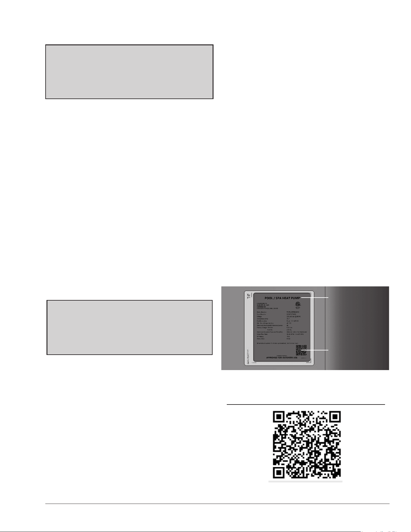
Using Figure 1, please locate and record your model and
serial number. Once you have done this, please make sure
you also have the following information on hand:
• Name, phone number, and email address of
homeowner
• Physical address of where the unit is installed; please
include any ‘subdivision’ or similar information
Figure 1. Model and Serial Number Location
Warranty Registration Conrmation #:
Scan this QR with your smart device to register or verify
your new Raypak heater.
Nameplate
QR Code
• Any service challenges present at the house/
neighborhood: gated community, locked access at
house, guard dog, etc.
• Date of installation of the new unit
• Name and phone number of the professional and
licensed entity that performed the installation for you
With all of the above information in hand, please contact
Raypak and ask to register your brand new heat pump or
Online at:
https://www.raypak.com/support/registration_warranty/
You will be given a Warranty Registration Conrmation
number which you should notate and keep in one location
along with your Installation & Owner’s Manual, a copy of
your warranty (provided with your manual) and the above
information.
This unit is equipped with a QR Code on the rating plate, as
shown in Figure 1, which will take you to the www.raypak.com
website where the Installation & Owner’s manual and other
documents can be easily accessed.
This would also be a good time to review both the manual
and the warranty so that you are aware of how to correctly
operate your new equipment as well as how to keep from
voiding any aspects of your warranty. During the life of your
unit, please feel free to use the phone number conveniently
located right on the unit, to contact us with any questions you
may have about operation, warranty, and/or service.
Thank you very much choosing Raypak to satisfy your pool
heating needs!!
6
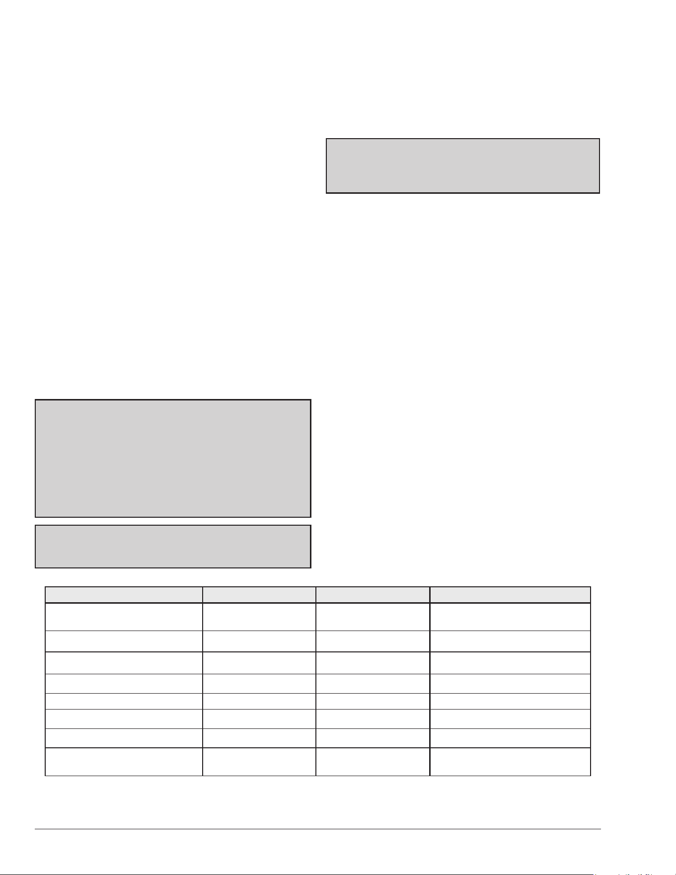
Recommended Level(s) Fiberglass Pools Fiberglass Spas Other Pool & Spa Types
Water Temp.
68 °F to 88 °F
(20°C to 31°C)
89 °F to 104 °F
(32°C to 40°C)
68 °F to 104 °F
(20°C to 40°C)
pH 7.3 to 7.4 7.3 to 7.4 7.6 to 7.8
Total Alkalinity (PPM) 120 to 150 120 to 150 80 to 120
Calcium Hardness (PPM) 200 to 300 150 to 200 200 to 400
Salt (PPM) 4500 MAXIMUM 4500 MAXIMUM 4500 MAXIMUM
Free Chlorine (PPM)* 2 to 3 2 to 3 2 to 3
Total Dissolved Solids (PPM) 3000 MAXIMUM** 3000 MAXIMUM** 3000 MAXIMUM**
Water Pressure (psi/kPa)
5 MIN. - 70 MAX.
(35 MIN. - 483 MAX.)
5 MIN. - 70 MAX.
(35 MIN. - 483 MAX.)
5 MIN. - 70 MAX.
(35 MIN. - 483 MAX.)
*Free Chlorine MUST NOT EXCEED 5 PPM!
** In salt water chlorinated pools, the total TDS can be as high as 6000 ppm.
Table A. Water Chemistry
3. WATER CHEMISTRY
IMPORTANT: Corrosive water voids all
warranties.
For your health and the protection of your pool equipment,
it is essential that your water be chemically balanced. The
following levels in Table A must be used as a guide for
balanced water.
• Occasional chemical shock dosing of the pool or spa
water should not damage the heater providing the
water is balanced. However, it is highly recommended
that the heat pump pool heater is isolated via shut off
valves before any aggressive chemical treatment.
• Automatic chemical dosing devices and salt
chlorinators are usually more efficient in heated
water. Unless controlled, they can lead to excessive
chlorine level which can damage your heater.
• Further advice should be obtained from your pool
or spa builder, accredited pool shop, or chemical
supplier for the correct levels for your water.
4. INSTALLATION
CONSIDERATIONS
A
WARNING: Do not install the unit within 3 ft (0.9 m) of
fossil-fuel-burning heaters. Air intake along the sides of
this heat pump pool heater could disturb the combustion
process of the unit, and could cause damage or personal
injury.
● Mount the unit on a level, sturdy base, preferably a
concrete slab. The size of the base should be at least 3 ft
by 3 ft (0.9 m x 0.9 m) - slightly larger if hurricane tie-down
brackets are installed. See Figure 5 for more details.
CAUTION: The unit’s supporting base must be high
enough to keep it completely free of standing water at
all times.
Situate the heater carefully to minimize installation costs
while providing maximum efciency of operation, and to
allow adequate service access, as follows:
• For unrestricted air intake and service access,
position each side of the unit at least 1 ft (30 cm)
from walls, pipes and other obstructions.
A
WARNING: This unit is designed for outdoor
installation. It is NOT certied for indoor installation.
DO NOT install it in an enclosed area such as a shed or
garage, or under a porch or deck.
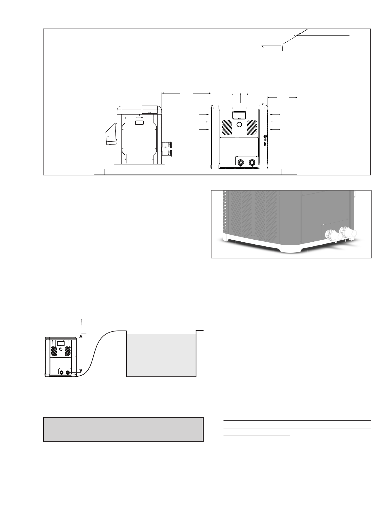
• This unit features an ‘up-flow’ discharge for quiet
operation. Air is pulled up through the evaporator
coil and discharged through the top grill. Allow
at least 5 ft (1.5 m) clearance above the unit for
unrestricted air discharge. Do NOT install the
unit under a porch or deck. Refer to Figure 2 for
installation clearances. Allowing cold discharge air to
recirculate back into the evaporator coil will greatly
reduce the unit’s heating capacity and efficiency.
To minimize water piping, locate the unit as close as
possible to the existing pool pump and filter.
• Irrigation water should be directed away from the
heat pump pool heater - irrigation water spray can
damage the heater.
• Rain water runoffs - the unit is designed to operate
outdoors and can be exposed to rain. However, rain
water runoff falling directly onto the unit can cause
damage and/or shorten the life of your unit. Such
damage is NOT covered under warranty. Install rain
gutters or rain diverters on your roof if the unit is
installed in a position where contact with rain runoff
may occur.
• It is important to keep the area next to the heater
clear of shrubs, bushes and chemicals containers.
They could prevent air from circulating fully through
the heater, and will affect the operation of the heater
or damage the heater.
7
3’
(0.9 m)
MIN
AIR
FLOW
IN
AIR
FLOW
IN
AIR FLOW OUT
60" (1.52 m) MIN
12"
(0.3 m)
MIN
RAIN DIVERTER
RAIN GUTTER
Figure 2. Installation Clearances
• When installed in areas where freezing temperatures
can be encountered, drain the water circuit to
prevent possible freeze-up damage. Refer to "Freeze
Protection" on page 35 for proper procedures.
• When the heater is located below the water line of
the pool or spa, it may be necessary to adjust the
Water Pressure Switch (WPS) to compensate for the
no-flow static head (see Figure 3). For more details
about adjustment, please refer to the Water Pressure
Switch section on page 30. If after adjusting the
WPS to its maximum setting without resolution, an
external Water Flow Switch (WFS) must be installed.
See "Water Flow Switch" section below for further
installation instructions.
MAY REQUIRE ADJUSTMENT
FOR HIGHER PRESSURE
POOL OR SPA
WATER LINE
Figure 3. Water Pressure Switch Adjustment
• For high-wind installation requirements, refer to
Figure 5 – depending on the model size.
Water Flow Switch
If the heater is located below the water line of the pool,
an external Water Flow Switch (WFS) must be installed.
The WFS is NOT provided with the heater. A WFS must
be installed as per the following instructions to prevent
nuisance heater tripping (for example: high-pressure
switch fault) and to ensure proper operation. WFS kit (P/N:
H000166) is available as an optional service kit.
1. Install the WFS onto the water inlet piping as shown
in Figure 68 on page 41.
2. The WFS must be installed before any bypass or
check valve assembly.
3. The WFS must be installed within a straight,
horizontal piece of inlet piping of at least 5" in length.
The WFS sensor is sized for 1.5" pipe, but can be
converted to 2" if required.
4. The WFS must be installed in close proximity to the
heater, Raypak recommends to install no further
than 2 ft. per Figure 68.
5. Connect the WFS per the wiring instructions located
on page 86.
Figure 4. Base Design - Handling
NOTE: The base is designed with recessed areas to allow
the use of hand trucks or lifting without the possibility of
pinching ngers as shown in Figure 4.
8
UNIT HEIGHT
37.8” MAX
UNIT WIDTH
33.6” MAX
UNIT LENGTH
33.6” MAX
CONCRETE SLAB
BY OTHERS, TYP.
UNIT WIDTH
33.6” MAX
UNIT LENGTH
33.6”
MAX
UNIT HEIGHT
37.8” MAX
CONCRETE SLAB
BY OTHERS, TYP.
CONTROL
COVER
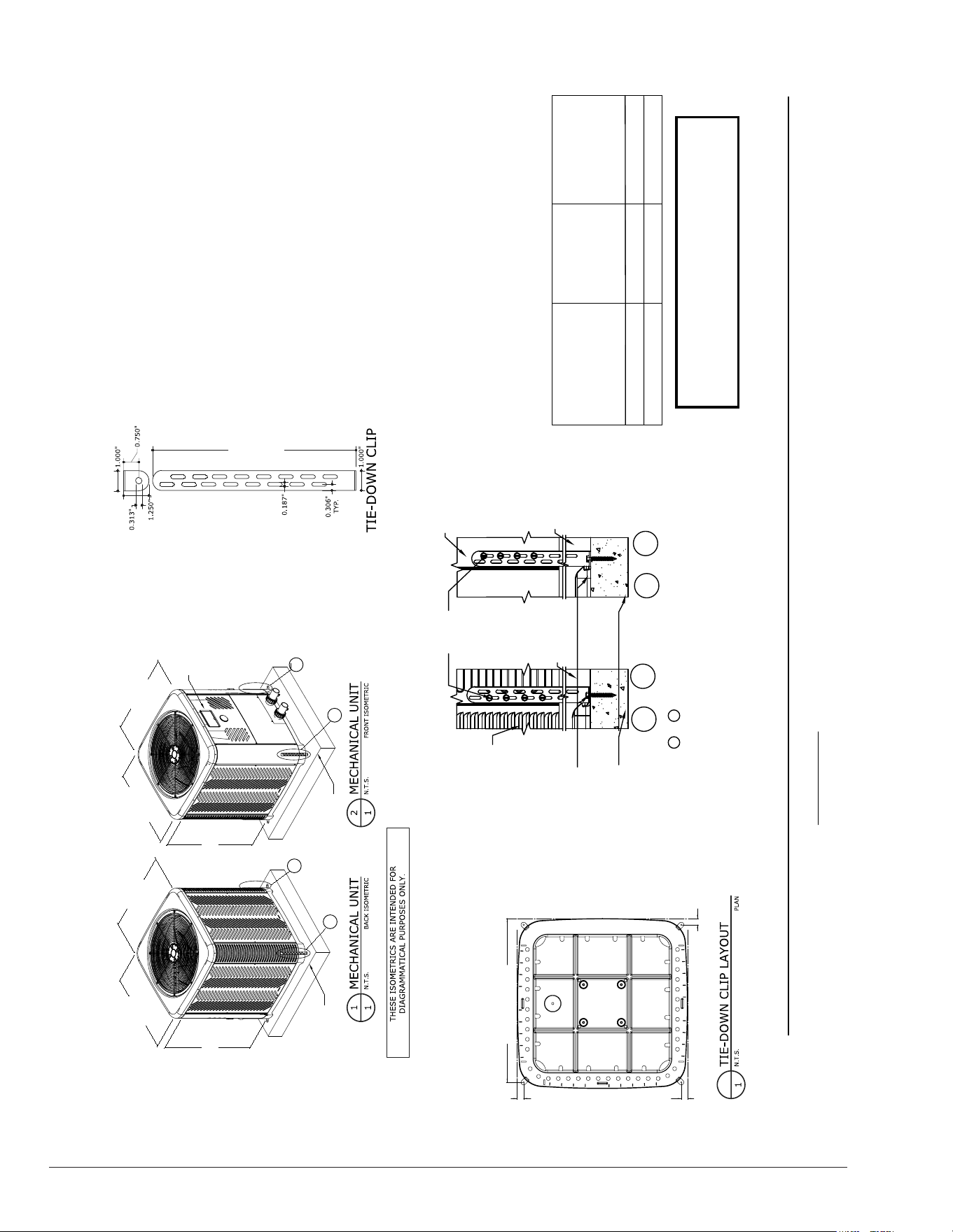
3
Maximum Rated Wind Pressures:
± 140 psf Lateral, 111 psf Uplift
Hurricane tie-downs are a structural component designed to prevent wind uplift during severe weather, such as hurricanes or severe storms. For further information on tie-downs,
and technical support, contact Raypak at www.raypak.com or call 805-278-5300.
Minimum pad dimensions are 43-1/4”
x 43-1/4” x 4” thick.
Screws to attach brackets to unit are
supplied with the unit.
DO NOT use screws not specified or
provided by manufacturer. Screws
are stainless steel #10 x 3/4”
self-drilling. Each bracket requires 4
screws attached to the unit.
Miami Tech Clip: (0.07”) ASTM A653
Fu=90 KSI Steel (CUTD10) or 0.080”
5052-H32 Aluminum (CUTDA10). Florida
approval FL# 19731.1 or approved equal.
TIE-DOWN SCHEDULE
At-Grade ± 54 psf (0 psf) 4
At-Grade / Rooftop ± 140 psf (111 psf)
8
Installation
Condition
Max. ASD
Wind Pressures
Lateral (Uplift)
1.26 TYP.
32.5 TYP.
1.26 TYP.
1.26 TYP.
# of
Tie-Down
Clips
8.00”- 10.00”
A
B
C
D
(4)-#10
SMS PER
CLIP, TYP.
D
A & B
3000 PSI MIN.
CONCRETE BY
OTHERS, TYP.
ANCHOR PER
SCHEDULE
LOUVER
PANEL,
TYP.
UNIT BASE
PAN
UNIT BASE
PAN
A & C ARE SIMILAR
AND OCCUR ON
OPPOSITE FACES
FRONT CORNER PANEL
C
&
Figure 5. Hurricane Tie Down Instructions – Models: TWPH 4550, 5550, 6550, 6550EHC, 8550, & 8550EHC
9
5. WATER CONNECTIONS
CAUTION: The heater inlet and outlet are NOT
interchangeable. They must be connected as instructed
below.
A
WARNING:
Improper installation of any type of
automatic chemical feeders can result in serious damage
to, or premature failure of, the heater and such damage
will not be covered under warranty. Install a check valve
and/or a Hartford loop AFTER the heater and BEFORE
any chlorinating devices. Install any automatic chemical
feeders AFTER the heater.
1. Connect the heater in the return water line between
the filter and the pool/spa. See plumbing diagrams
on page 39 (without bypass) and page 40 (with
bypass).
2. Connect the filter outlet to the fitting marked INLET at
the bottom front of the unit.
3. Connect the fitting marked OUTLET to the return
piping to the pool/spa. Unit inlet/outlet connection
fittings are 2-inch PVC unions on models 4550-8550.
Water connections from the unit to the main return line can
be PVC pipe or exible pipe approved for the purpose and,
in either case, should be at least equal in size to the main
pool/spa circulation piping.
• Water flow to the unit will exceed 40 GPM (151 LPM)
for 4550 models or 50 GPM (189 LPM) for 5550-
8550 models. See Figure 67 for bypass instructions.
• To protect (completely bypass) the unit from any
harmful chemical treatments (i.e. Acid wash, back-
to-back super chlorinators, stain treatments, etc.); or
to be able to isolate the unit for service/repair or
freeze preparation and still allow pool/spa circulation
to continue.
In Heat/Cool models, a bypass assembly is included.
Please refer to the plumbing on page 40, for further
instruction.
Please note that some municipalities do not allow the use
of a shutoff valve on the efuent/outlet side of any heating
equipment, especially when there is one on the inlet side.
These entities typically instead allow a PVC tee and spring
check valve on the efuent/outlet side. This is allowed
by Raypak and can also double as your protection from
chemical feeders and chlorinators that are downstream of
the unit.
4. Operate the pump and check the system for leaks.
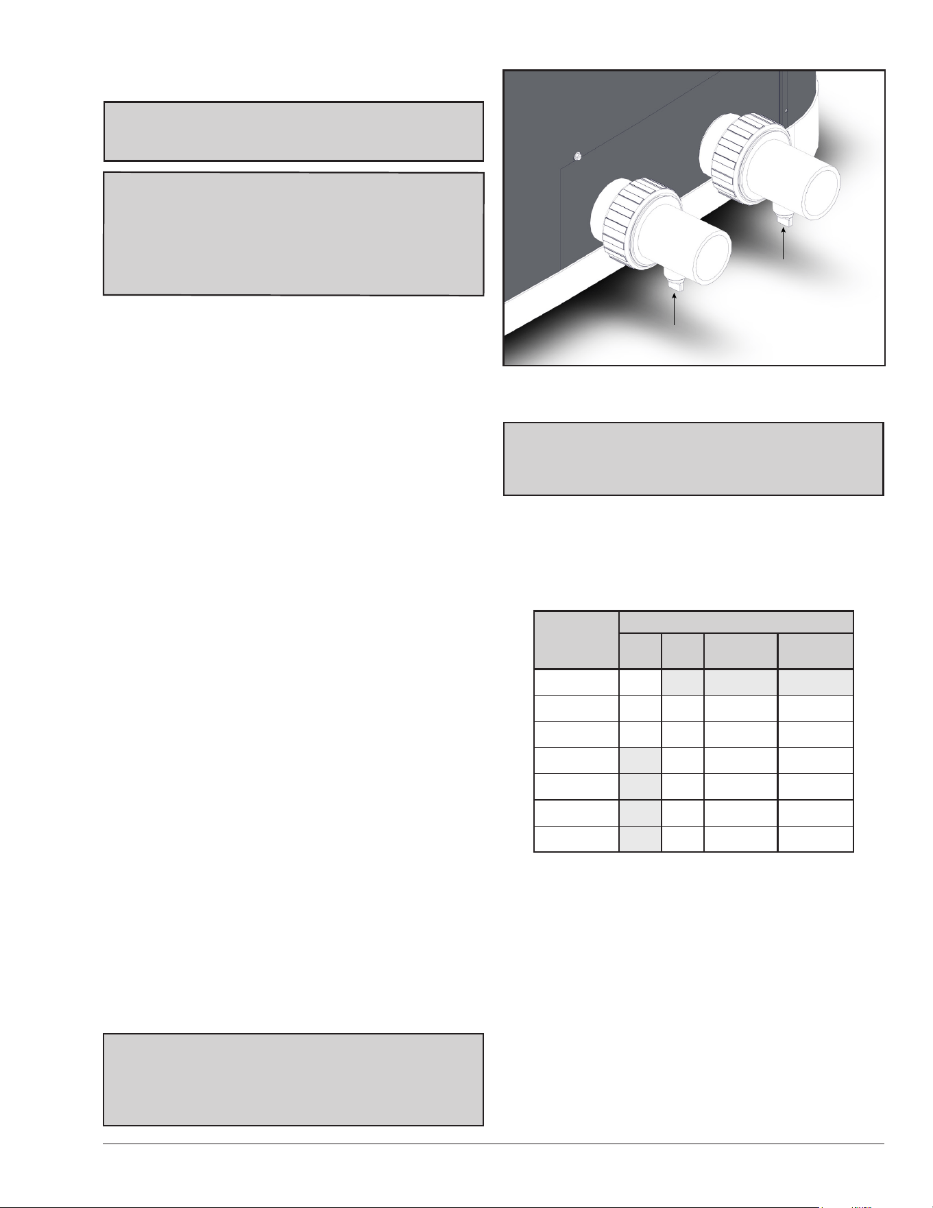
5. Drain plugs are located on each union fitting as shown
in Figure 6 for draining the system during winterizing.
NOTE: While it is possible to mount the upper union
with the drain plug vertically, the manufacturer has
determined that installing both unions with the drain
plugs facing down, as shown in Figure 6, provides for
the best draining of the system.
Figure 6. Water Connections/Drain Plugs
CAUTION: When the drain plugs are removed for
draining the system, ensure that they are stored in a
safe place for re-installation when needed to restart the
system.
6. FLOW RATE & PRESSURE
DROP
For system pressure drop information, see Table B.
Flow
GPM (LPM)
Pressure Drop (PSI)
4550 5550
6550/
6550EHC
8550/
8550EHC
20 (750) 3.4
30 (113) 7 4 6 9
40 (151) 13 7 9 9
50 (189) 10 10 10
60 (227) 11 11 11
70 (265) 12 12 12
80 (303) 13 13 13
Note: Minimum recommended ow is 20 GPM. Multiply the pressure drop
in psi by 2.3067 to yield the pressure drop in Ft. H
2
O Head.
(Total Dynamic Head TDH)
Table B. Flow Rate & Pressure Drop Across the Heater
INLET
OUTLET
DRAIN PLUG
DRAIN PLUG
10
Model
No.
Power
Min.
Circuit
Ampacity
Breaker Size (AMP) Recommended Wire Length from Breaker to Heater*, ft. (m)
MIN. MAX. 12 AWG 10 AWG 8 AWG 6 AWG 4 AWG
4550
208/230V
- Single
Phase -
60Hz
38 50 60 NR** 89 (27.1) 142 (43.3) 225 (68.6) 359 (109.4)
5550 40 60 70 NR** 94 (28.7) 151 (46.0) 239 (72.8) 383 (116.7)
6550 46 60 70 NR** 97 (29.6) 156 (47.5) 247 (75.3) 396 (120.7)
8550 46 60 70 NR** NR** 110 (33.5) 175 (53.3) 280 (85.3)
* Reference only - see National Electrical Code or local codes for wire gauge length limits.
** NR= Not Recommended.
Table C. Typical System Electrical Power Requirements
7. ELECTRICAL
CONNECTIONS
Refer to the unit rating plate below the control panel for
precise power requirements for your unit, and for ampacity
and over-current protection requirements.
All wiring must be in accordance with the National Electrical
Code, NFPA No. 70, latest edition, and all applicable state
and local codes. See wiring diagram on page 11.
A
WARNING: This unit MUST be installed using
exible conduit for supply wiring to the unit. This will
allow movement of the conduit whenever the junction
box is removed for service - see "Service Access to
Heaters" on page 38.
• Locate the equipment disconnect means within 3
feet (0.9 m) of the heater’s electrical enclosure, or
as close to the heater as possible. Always satisfy
applicable codes and standards.
• A means to fully disconnect the unit from the main
power supply must be incorporated in the wiring of
the unit.
NOTE: Refer to the National Electrical Code, Article
680, for general requirements for swimming pools and
equipment, and to Article 440 for special considerations
necessary for circuits supplying hermetic refrigeration
motor/compressors.
• In sizing power wiring, be especially aware of up-sizing
requirements necessary due to wiring distances.
Always satisfy applicable codes and standards.
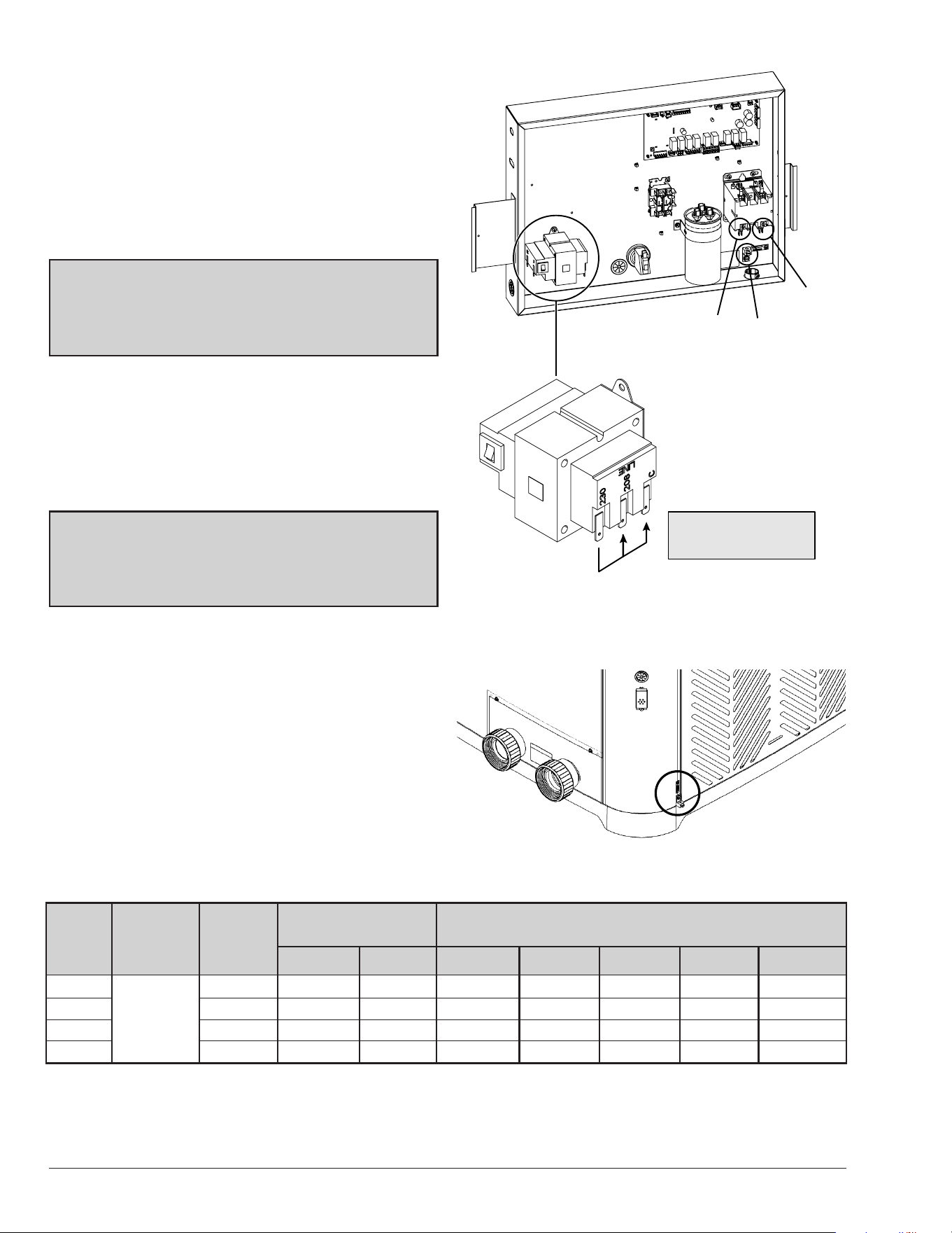
• Connect electrical Line 1 (L1) and Line 2 (L2) to
the terminals indicated in Figure 7 for proper wiring.
Electrical installation should be performed by a
licensed electrician only.
This unit is compatible to work with external control
systems, (optional harness provided in the packaging
per NOTE on page 5) heat-on-demand options and other
external time clock overrides. Refer to the external control
system’s instructions, and "Remote Mode Selector", on
page 32 of this manual, for installation information.
L1
GND
L2
For 208V operation, ensure to
change the transformer to the
208V and C Terminals.
Figure 7. Terminals L1 and L2
An earth ground lug is located to the right-side of the water
connections.
Figure 8. Earth Ground Lug
GROUND LUG
11
USE COPPER WIRES ONLY
USE 75°C 600V WIRE
TORQUE SCREWS: 40 IN-LB
11
1
1
10K
10K
10K
100K
BK/BU
BK/BU
BK/RD
BK/RD
RD
RD
GN
GN/BK
GN
1 1
BN
BU
YE
BN
RD
YE
OG
OG
BN
YE
BN
YE
R V
BU
RD
C
F
H
C
F
H
1
`
YE
BU
YE BU
VT
VT
24VAC
208V
240V
T1
L1
T2
L2
C2
C1
CONTACTOR
T1
L1
T2
L2
C2
C1
CONTACTOR
C
S
R
C
S
R
COMPRESOR
C
S
R
COMPRESOR
RD
RD
BK
BK
RD
POWER SUPPLY:
208/240V – 1 PHASE – 60Hz
L1 L2
GND
FAN
MOTOR
WPS/WFSLPSHPS
YE
BK
RD
BK
OG
BN
C2
C1
14
36
C2
C1
14
36
GY
GY
BK/WH
RD/WH
BN
11
3A 3A
RS-485
COMM
OUTLET
TEMP
P12
P13
P10
P6
FLOW
SENSOR
TEMPERATURE
SENSORS
P16
USER INTERFACE
P7
REMOTE
SELECTOR
POWER
24VAC
P1
MAIN
FUSE
VALVES
FUSE
F1
F2
VARIABLE
SPEED PUMP
P8
PUMP
P5
P19P20
3-WAY
VALVE2
3-WAY
VALVE1
AUX2
AUX1
P4
P3
P11
P9
P2
FAN, REV. VALVE AND
COMPRESOR COIL
FAN RVS COMP
SOLAR
3-WAY VALVE
SAFETY SWITCHES
WPS LPS HPS
MODESERVICE
DOWN
UP
CONNECT
MODESERVICE
DOWN
UP
CONNECT
BN
BN/OG
YE
BU
1
COMPONENT CODE
SENSOR 10K
DUAL SENSOR 100K
PRESSURE SWITCH
R V
REVERSING VALVE
CAPACITOR
CAPACITOR
GROUND
FAN RELAY
24VAC
TRANSFORMER
WIRE COLOR CODE
WPS
WFS
WATER PRESSURE SWITCH
WATER FLOW SWITCH
HPS
HIGH PRESSURE
SWITCH
LPS
LOW PRESSURE
SWITCH
GND
GROUND LUG
BK
BN
BU
GN
GY
VT
OG
RD
WH
YE
BLACK
BROWN
BLUE
GREEN
GRAY
VIOLET
ORANGE
RED
WHITE
YELLOW
OUTLET
INLET
COIL
AMBIENT
INSERT
A
NC NO COM L1 L2 L2
VOLTAGE MONITOR
NC NO COM L1 L2 L2
VOLTAGE MONITOR
L1 L2TRANSFORMER
NC NO COM L1 L2 L2
VOLTAGE MONITOR
L1 L2TRANSFORMER
INSERT
A
NC NO COM L1 L2 L2
VOLTAGE MONITOR
L1 L2TRANSFORMER
BK/BU
BK/BU
BK/RD
BK/RD
RD
RD
GN
GN/BK
GN
VT
VT
(HEAT/COOL ONLY)
24VC
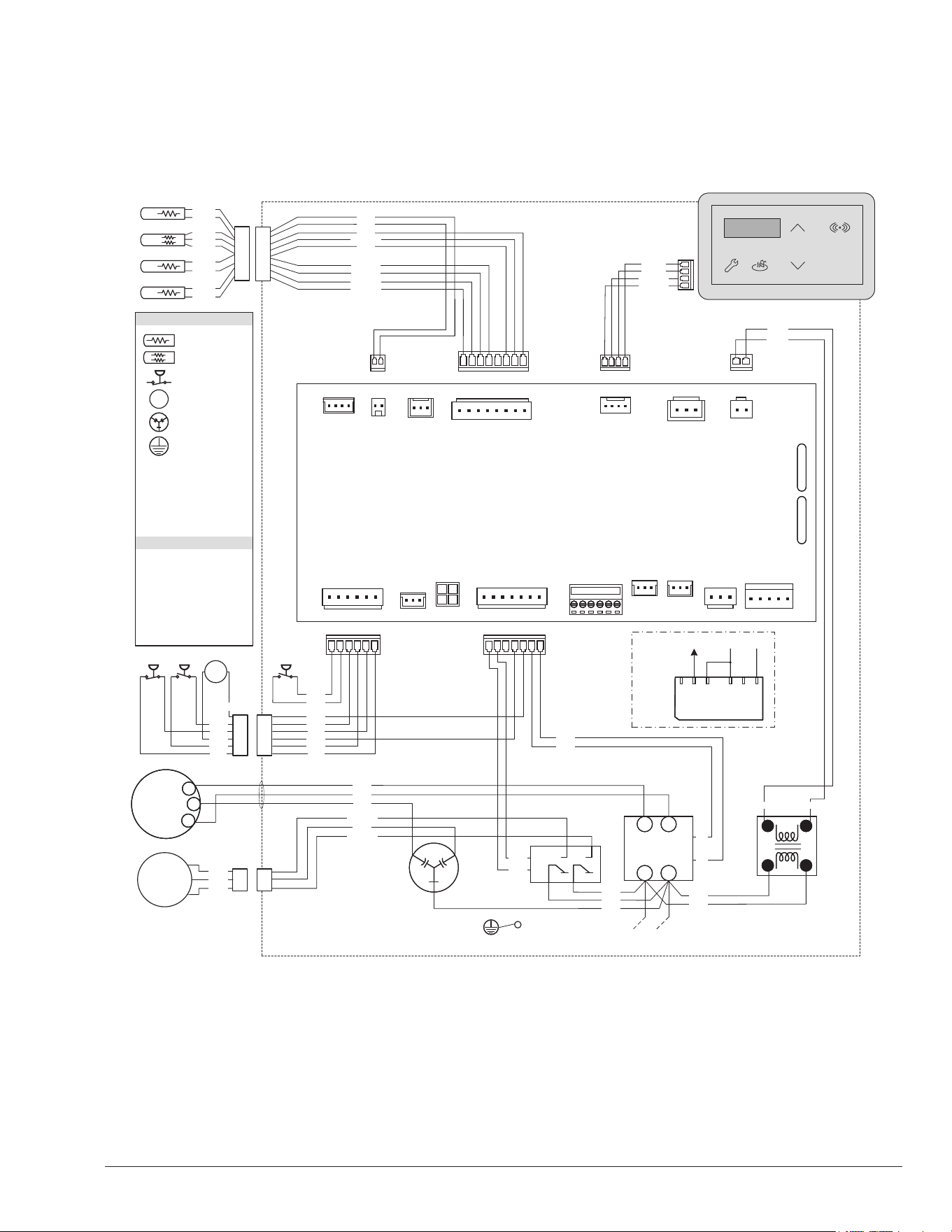
208V/230V Single-Phase – Heat only and Heat/Cool models
8. WIRING DIAGRAM
Figure 9. Heat Only and Heat/Cool Models Wiring Diagram
12
9. HEATER CONTROL
DISPLAY
The heater display is located in the front panel of the heat
pump, covered with a door. All operation and settings of
the heater control are accomplished through the use of the
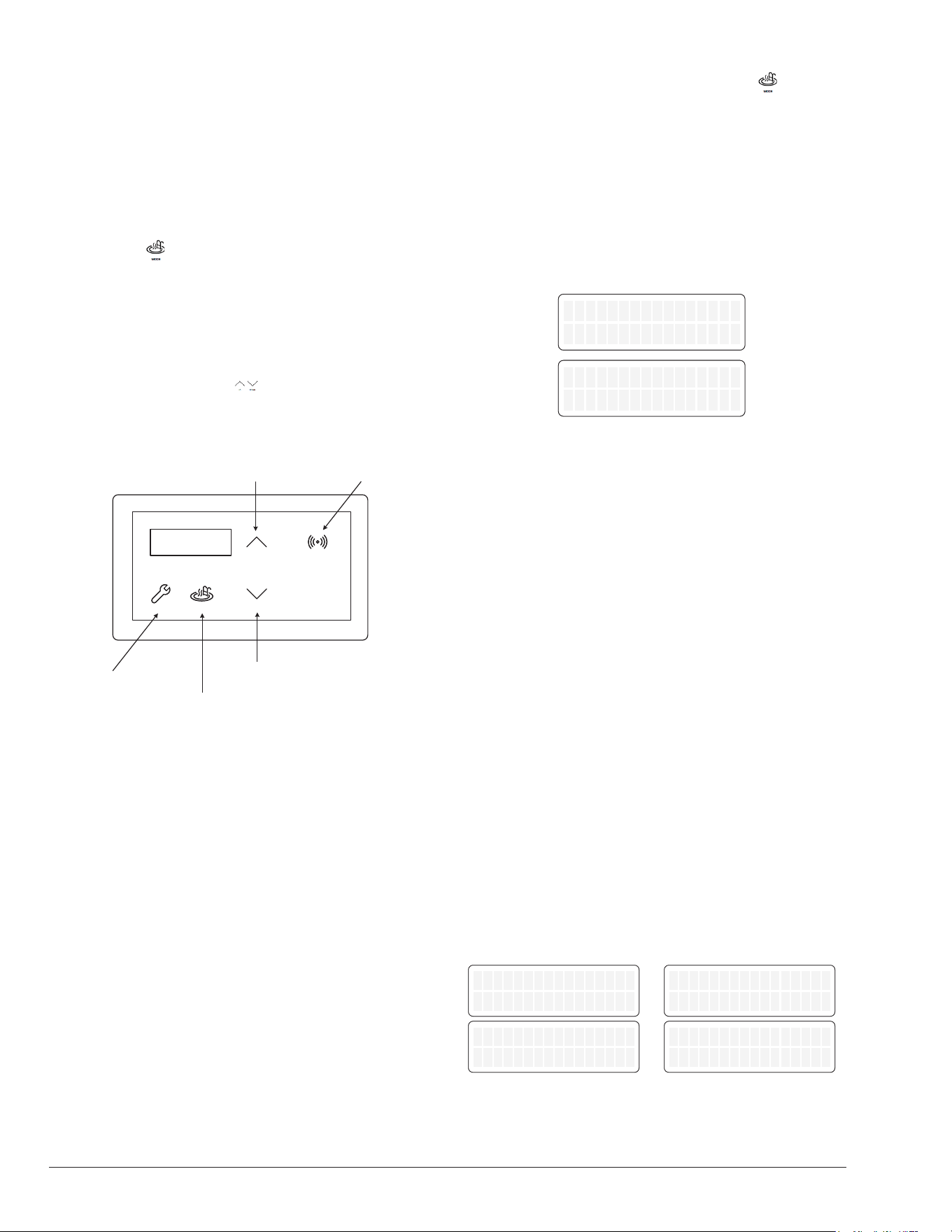
ve (5) touch keys of the user interface. These keys are
displayed in Figure 10.
Mode Key
The Mode Key is used to select one of several modes
for pool or spa operation. It also allows the user to select
the OFF mode of operation, during which the LCD, while
displaying OFF, continues to show the water temperature.
Refer to section 10, "Operation Modes" for details.
UP and DOWN Keys
If the heater is in pool or spa mode, the desired water
temperature (SETPOINT), can be adjusted using the UP
or DOWN keys.
MODESERVICE
DOWN
UP
CONNECT
CONNECT MENU
SERVICE MENU
Control 1.0
UI 1.0
UP TEMP ADJUST
DOWN TEMP ADJUST
MODE KEY
Figure 10. Heater Control Display
The display shows information on a 2-line, 16-character
back-lit Liquid Crystal Display (LCD). The back-light is
normally off, but it turns on for 5-minutes after power-up
and for 5-minutes after any button press. Use the LCD to
set up and monitor the operation of your heater.
If the control keys remains inactive for 5-minutes, the
screen will revert to the current view.
On a normal power-up, the control displays the current
software revision on the LCD for 2-seconds and then
resumes the user-selected mode it was in before power
was interrupted.
If unit type has not been set (like during the replacement
of the control), the control prompts the user to set the
model type (Heat Only or Heat/Cool) before any device
operation is enabled.
Upon initial installation, there are several items that
can be dened and programmed depending on the
conguration and accessories intended to be controlled
by the heater. Refer to "Program Menu" section on page
17 for details.
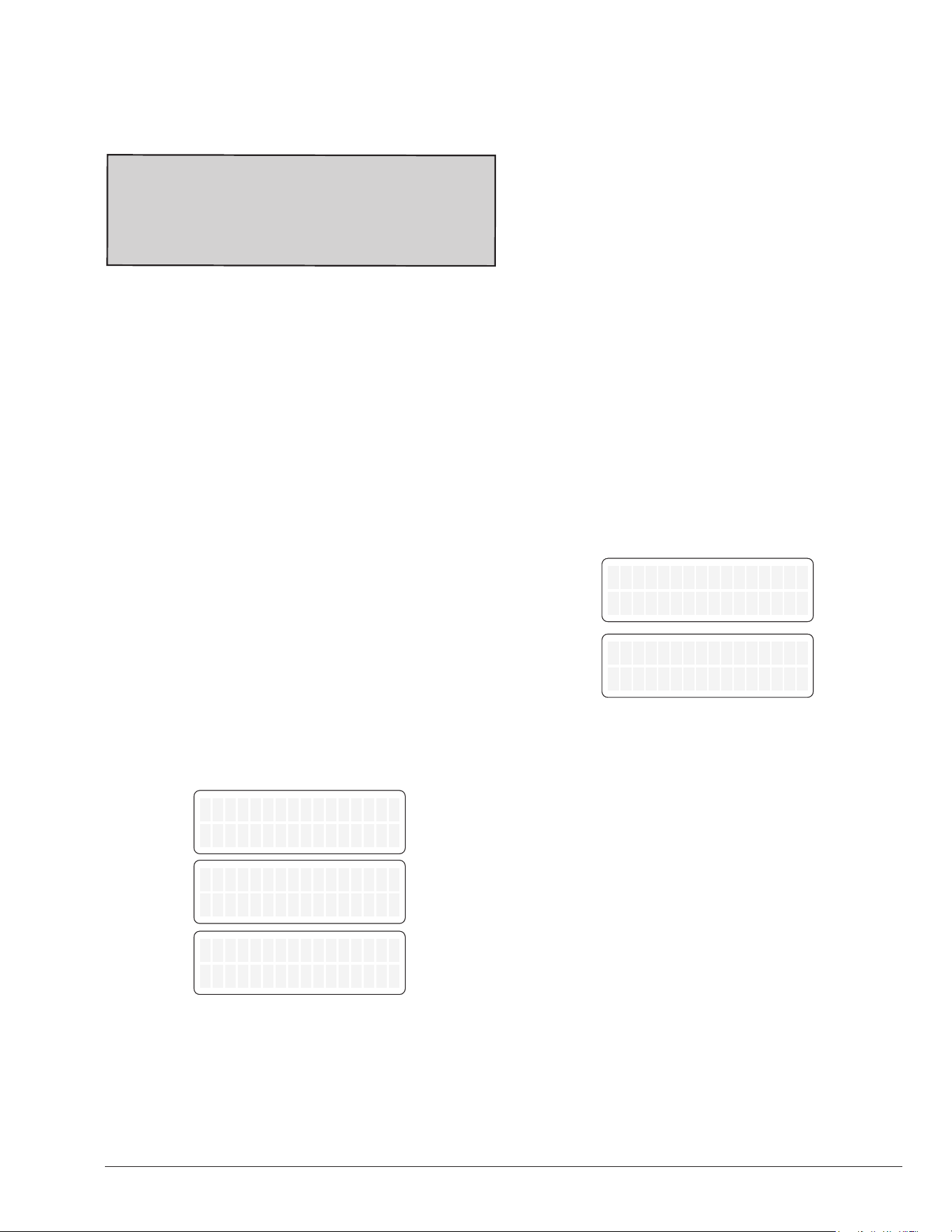
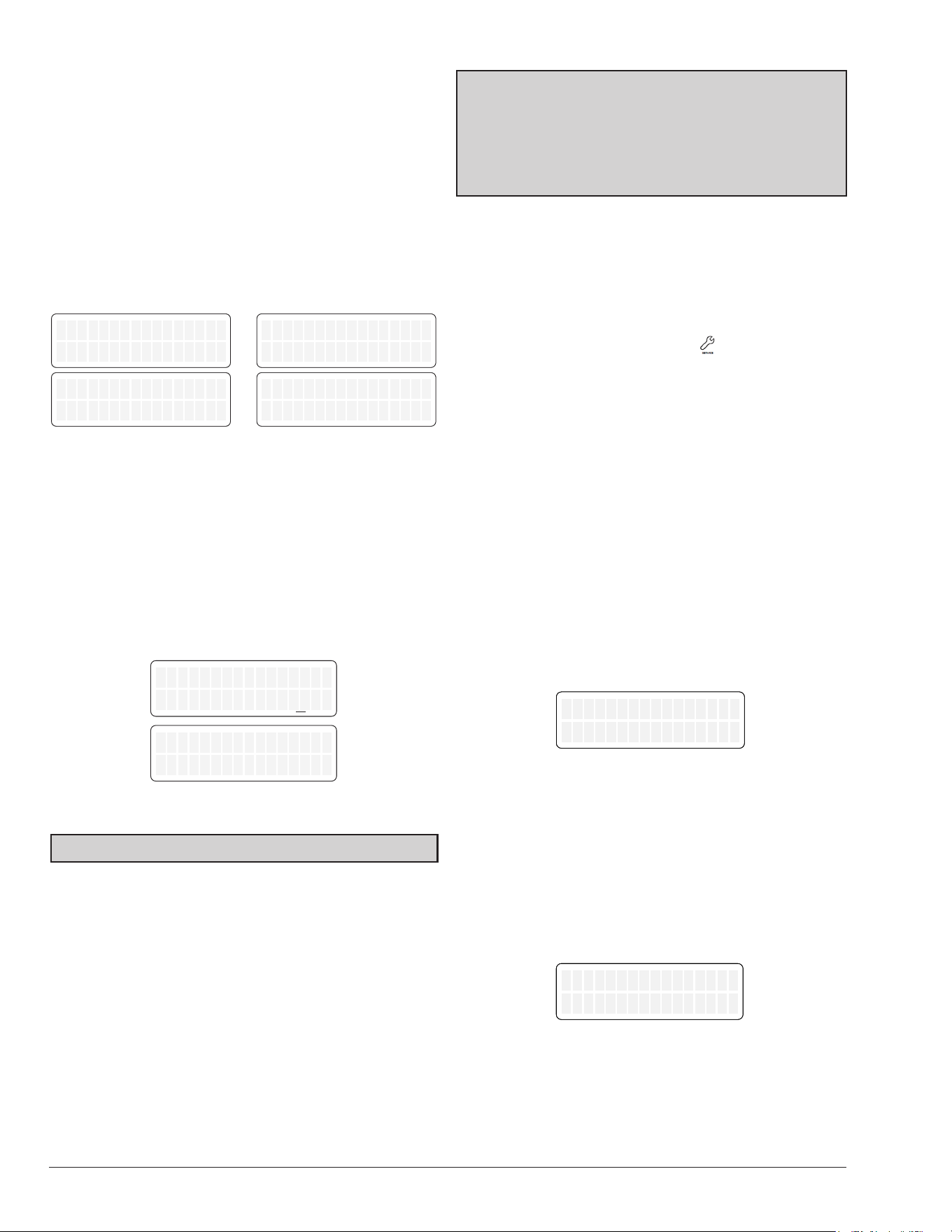
10. OPERATION MODES
The user may select one of several operating modes.
Each mode is selected by pressing the MODE key to cycle
between the modes. Each press of the MODE key selects
the next mode.
On Heat Only models, the options available by pressing
the MODE key are POOL, SPA, TIMED SPA and OFF.
On Heat/Cool models, the options available by pressing
the MODE key are POOL COOL, POOL HEAT, POOL
AUTO, SPA, TIMED SPA and OFF.
OFF
Water Temp 68F
OFF 8:05P
Water Temp 68F
OFF
No Demand
OFF
No Demand
8:05P
Figure 11. Alternating Display
Pool [Heat] and Spa Modes
The control is equipped with a Pool (heat) and Spa modes
which will automatically heat the pool to the heating
setpoint established in the selected mode.
The top row of the LCD displays the operation mode and
temperature setpoint. When Pool (heat) or Spa mode is
selected, each press of the UP or DOWN key will increase
/ decrease the water heating setpoint temperature. Holding
the UP or DOWN keys down will speed up the change of
the temperature values.
In these modes, the heater is set to heat when the water
temperature is 1°F (0.5°C) degree below the selected
temperature (setpoint). Heating is terminated when
setpoint is reached.
When the water temperature is above the setpoint, the
LCD will alternate “Water Temp” with “No Demand.” When
the water temperature is below the setpoint and the unit is
heating, the LCD will alternate “Water Temp” with “Heating”.
In POOL mode, default temperature setpoint is 80°F
(27°C) with a maximum temperature limit of 95°F (35°C).
In SPA mode, the default temperature setpoint is 100°F
(38°C). with a maximum temperature limit of 104°F (40°C).
Refer to "Program Menu", on page 18, to adjust pool or
spa maximum temperature limits.
Pool set 85F
Heating
Pool set 85F
Heating
Pool set 85F
Water Temp 68F
Pool set 85F
Water Temp 68F
Spa set 100F
Heating
Spa set 100F
Heating
Spa set 100F
Water Temp 68F
Spa set 100F
Water Temp 68F
Figure 12. Pool Heat and Spa Modes
13
Timed Spa Mode
The control is equipped with a mode which will heat the
spa to the Spa setpoint temperature for a specied period
of time selected in the TIMED SPA mode setup.
A
WARNING:
If an external controller controls the spa
heating in a pool/spa system, manual adjustment of the
3-way valves may be necessary to use the TIMED SPA
feature of this heat pump. Failure to adjust the 3-way
valves properly may result in pool water overheating or
other undesirable results.
To activate the timed spa feature, press the MODE key until
“TIMED SPA” is displayed on the top line of the display.
The display will read “Up or Dn to Set”. This tells the user
to press the UP or DOWN keys to set the desired length of
time for the timed spa heating operation.
Press the UP or DOWN keys to select the desired duration
of spa heating, up to a maximum duration of 6-hours in
15-minute increments. After selection of time is completed
press MODE key to start heater operation.
The timer will start to count down from the selected period
and the unit will operate to heat the water based on the
previously selected spa setpoint temperature setting.
Once the unit turns on, the display will toggle between the
current spa water temperature and the current operating
state “Heating” and the timer.
The top row of the LCD displays the operation mode and
temperature setpoint. Timed Spa temperature setpoint
can be adjusted using the UP and DOWN keys while the
screen is displaying the Water Temperature and “Heating”
status.
To adjust the timer, press MODE key, then use the UP and
DOWN keys to increase or decrease the timer. To terminate
the timer, use DOWN key to set timer to 00:00:00.
When the TIMED SPA timer has expired, the control will
be set to OFF.
Timed Spa 100F
Up or Dn to Set
Timed Spa 100F
Up or Dn to Set
Timed Spa 100F
Heating 2:30:00
Timed Spa 100F
Heating 2:30:00
Timed Spa 100F
Water Temp 68F
Timed Spa 100F
Water Temp 68F
Figure 13. Timed Spa Mode
Pool Cool Mode - Heat/Cool Models Only
In heat/cool models, the control is equipped with a "Pool
Cool Mode" which will automatically cool the pool to the
cooling setpoint established in this mode.
The top row of the LCD displays the operation mode and
temperature setpoint. When pool cool mode is selected,
each press of the UP or DOWN key will increase /
decrease the water cooling setpoint temperature. Holding
the UP or DOWN keys down will speed up the change of
the temperature values.
In this mode, the heater is set to cool when the water
temperature is 1°F (0.5°C) degree above the selected
temperature (setpoint). Cooling is terminated when
setpoint is reached.
When the water temperature is below the setpoint, the
LCD will alternate “Water Temp” with “No Demand.” When
the water temperature is above the setpoint and the unit
is cooling, the display will alternate “Water Temp” with
“Cooling”.
In pool cool mode, default temperature setpoint is 80°F
(27°C) with a minimum temperature of 44°F (7°C) and
maximum temperature limit of 95°F (35°C). Refer to
"Program Menu", on page 18, to adjust pool maximum
temperature limits.
Pool Cool 85F
Cooling
Pool Cool 85F
Cooling
Pool Cool 85F
Water Temp 95F
Pool Cool 85F
Water Temp 95F
Figure 14. Pool Cool Mode
Pool Auto Mode - Heat/Cool Models Only
The control is equipped with a mode which will automatically
heat and cool the pool within the range of the heating
setpoint and the cooling deadband.
The top row of the LCD displays the operation mode and
temperature setpoint. When pool auto mode is selected,
each press of the UP or DOWN key will increase /
decrease the water setpoint temperature. Holding the UP
or DOWN keys down will speed up the change of the
temperature values.
In these modes, the heater is set to heat when the water
temperature is 1°F (0.5°C) degree below the selected
temperature (setpoint). Heating is terminated when
setpoint is reached. The heater is set to cool when the
water temperature is above the selected temperature
(setpoint) plus the specied cooling deadband. Cooling
is terminated when setpoint plus the cooling deadband is
reached.
14
Example: When pool auto setpoint is set at 80°F (27°C)
and cooling deadband set at 6°F (3.5°C), the unit will
automatically heat the pool if the temperature drops below
80°F (27°C), and will automatically cool the pool if the
temperature is above 86°F (30.5°C).
In pool auto mode, default temperature setpoint is 80°F
(27°C) with a minimum temperature of 44°F (7°C) and
maximum temperature limit of 95°F (35°C). Cooling
deadband default is 6°F (3.5°C), adjustable from 2 to 10°F
(1 to 5.5°C) degrees. Refer to "Program Menu", on page
18, to adjust pool maximum temperature limits and
cooling deadband.
Pool Auto 85F
Heating
Pool Auto 85F
Heating
Pool Auto 85F
Water Temp 83F
Pool Auto 85F
Water Temp 83F
Pool Auto 85F
Cooling
Pool Auto 85F
Cooling
Pool Auto 85F
Water Temp 92F
Pool Auto 85F
Water Temp 92F
Figure 15. Pool Auto Mode
Control Lockout Mode
Prevent unauthorized access to the heater's control
settings with the "Control Lockout" feature. To activate
the lockout, press and hold the MODE and DOWN keys
simultaneously for 5-seconds. Select a three-digit PIN by
using the UP and DOWN keys to select each digit and the
MODE key to lock in the selection. Conrm your selection
and make a record of your PIN for future reference.
Control Lockout
Enter PIN 000
Confirm Lockout
Yes
Figure 16. Control Lockout
NOTE: Record this lockout code for future reference.
To unlock the controls, select the ENTER PIN menu by
pressing the MODE key followed by the UP or DOWN key.
Enter the three-digit PIN that was previously used to lock
the control. Please note that power cycling will not clear
the lockout. A successful PIN entry will display "LOCKBOX
CLEARED," whereas an incorrect PIN will result in
"INVALID PIN" being displayed.
If the user-selected PIN is lost or does not clear the
Control Lockout, you can use the Code 101 to temporary
override the lock box and then the Program Menu to SET
FACTORY DEFAULTS. This will remove the PIN and allow
normal operation, including the selection of a new PIN if
desired. Refer to the "Program Menu" section on page 16
for detailed instructions.
NOTE: If you choose to set FACTORY DEFAULTS, the
pool and spa setpoints will return to their default values
of 85°F (29°C) and 100°F (38°C), respectively, and the
maximum temperature settings for pool and spa will be
reset to 95°F (35°C) and 104°F (40°C). It will be necessary
to readjust these setpoints to your preferred settings.
Additionally, other default congurations will be restored.
Keypad Protection
After 30-minutes of inactivity, the controller will automatically
protect the keypad to avoid unintended key presses. Follow
the on-screen instructions to unlock the keypad: Press the
UP key three times, followed by the MODE key, to unlock.
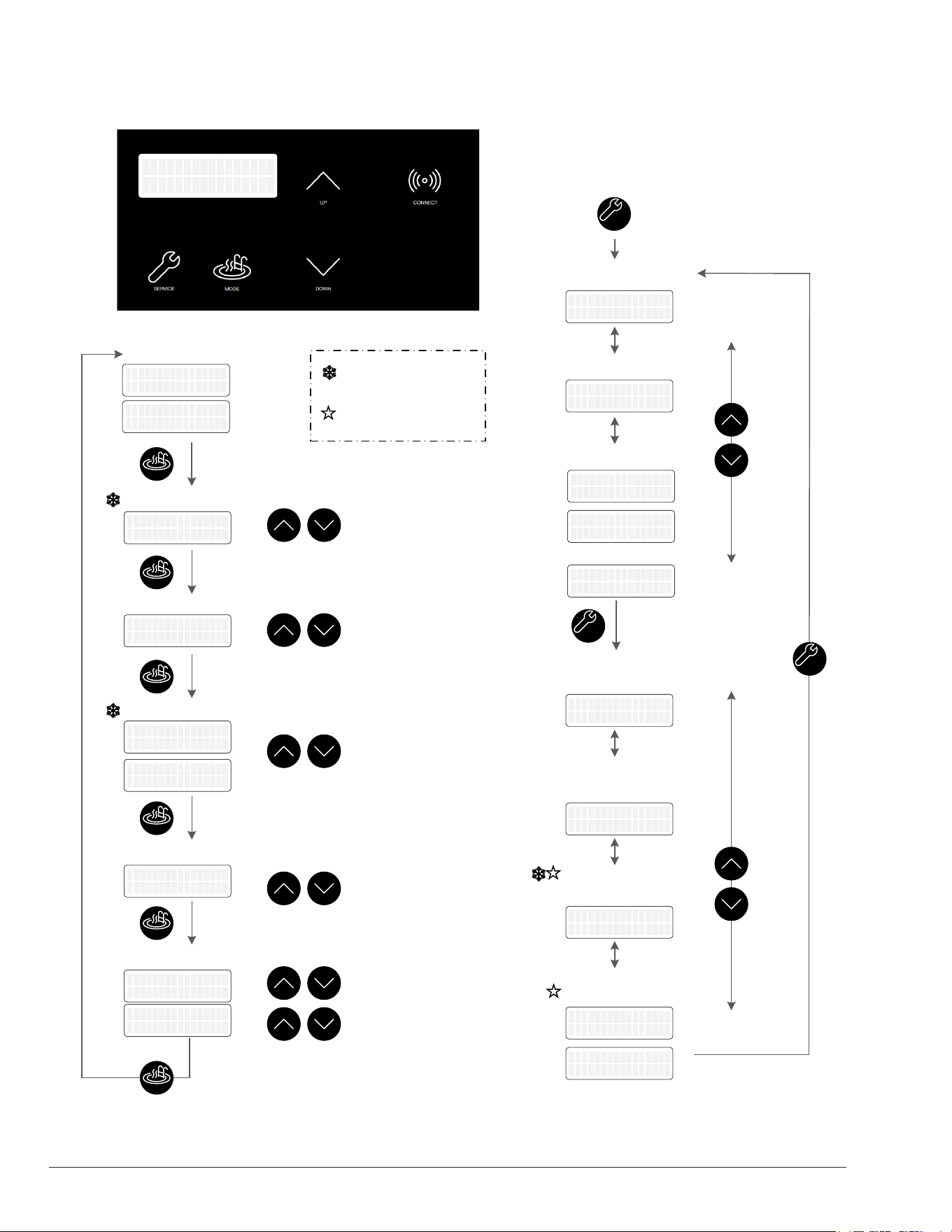
11. SERVICE MENU
To access the "Service Menu" and fault history, press the
SERVICE key 1-time. The heater will continue to operate
while in the service menu.
In this mode, pressing the UP or DOWN keys will toggle
through the various information reported. Some items
("Fault History" and "Sensor Temperatures") have multiple
values. Press UP or DOWN buttons to scroll through the
additional information. The SERVICE menu may be exited
to return to the previous display be pressing the MODE
key or it will automatically be exited if no key is pressed
within 30-seconds.
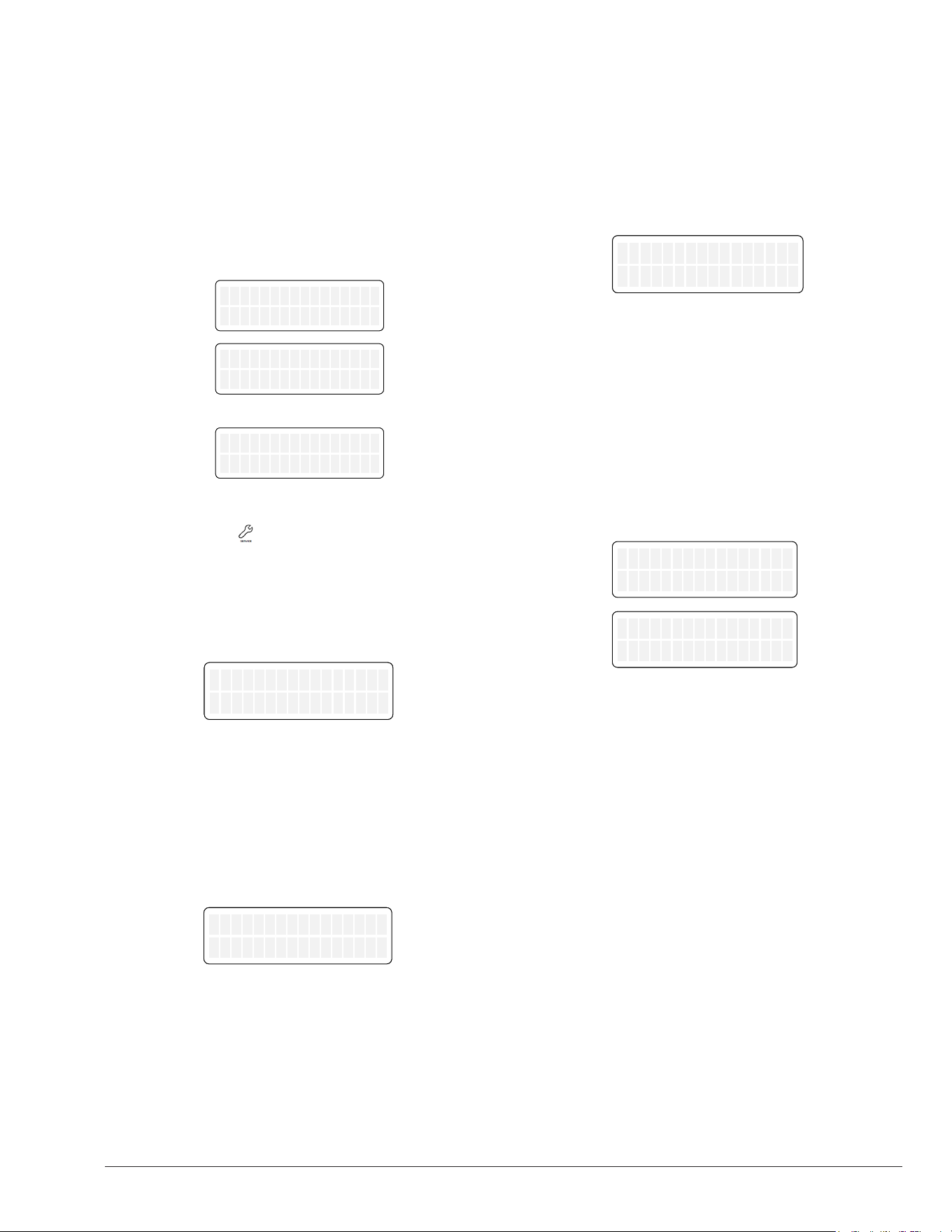
Supply Voltage
The rst screen displayed is the "Supply Voltage" indicator,
which indicates the voltage supplied to the control board.
Normal readings range from 24 to 30 volts.
Brownout Detect.
230V
Supply Voltage
24V
Figure 17. Supply Voltage Indicator
Run Time Hours and Cycles
Press the DOWN key. The "Hours" run time indicates the
total hours of operation for the pool heater, as measured
by the amount of time that the compressor has been
energized. The "Cycles" count indicates the number of on/
off cycles of the heater, as measured by the number of
times the compressor has been energized.
Brownout Detect.
230V
Hours 451
Cycles
89
Figure 18. Run Time/Cycles
15
Faults History
Press the DOWN key. The "Fault History" displays up to ten
faults in memory. The order of the faults begins with "Last
Err", which is the most recent fault, and proceeds through
the ten most recent messages in reverse chronological
order.
Run time hours at the moment of the fault are displayed
at the end of the rst line. The second line of the display
shows the "Fault" message. If there are no faults in the
history buffer, the second line reads “All Faults Clear.”
Brownout Detect.
230V
Last Err 450
Brownout Detect.
230V
Fault 9 241
Inlet Temp Fail
Brownout
or
Brownout Detect.
230V
Last Err 0
All Faults Clear
Figure 19. Fault History
Press the Service key again to access the Advance
Service Menu.
Heat Pump Temperatures
The "In/Out Temp" screen indicates the water temperature
sensed in the inlet and at the outlet of the heater.
Brownout Detect.
230V
HPPH Temp
In 68F, Out 78F
Figure 20. Inlet and Outlet Temperature
Coil and Outdoor Temperature
Press the DOWN key. The "Coil Temp" screen indicates
the temperature sensed, displayed on the rst line. The
second line displays the temperature sensed by the
outdoor sensor.
Brownout Detect.
230V
Coil Temp
Outdoor 68F
47F
Figure 21. Coil and Outdoor Temperature
Solar Heater Temperature
(Heat/Cool Models Only)
Press the DOWN key. When enabled from "Installers
Menu", the "Solar Temperature" screen indicates the
temperature sensed with the solar heater sensor. The
"In" reading indicates the inlet of the solar heater. Solar
inlet temperature readings should come from a eld-
supplied 10K temperature sensor. Solar "Out" displays the
temperature at the outlet of the solar heater. This reading
comes from the Heat pump inlet sensor. This screen is
only displayed if the option “Solar Heating” is enabled
from "Installers Menu". For more details about solar heater
integration refer to section 13 Installers menu on page
21.
Brownout Detect.
230V
Solar Temp
In 61F, Out 68F
Figure 22. Solar Heater Temperature
Pump Status
Press the DOWN key. When enabled from "Installers
Menu", the "Pump Status" screen indicates current pump
mode and speed selection.
Pump control is compatible with Raypak Protégé Variable-
speed Pump and 4 digital outputs speed selector. By
default, "Pump Control" is disabled. See page 21 to
select and congure "Pump Control" option.
Brownout Detect.
230V
Protégé Pump
Speed2 1500 RPM
Brownout Detect.
230V
Pump Status
Speed 2
Figure 23. Pump Status
16
OFF mode
POOL Auto mode
Supply Voltage
Run Counters
Faults History
Inlet & Outlet
Temperatures
Pump Status
SERVICESERVICE
MODEMODE
MODEMODE
SERVICESERVICE
UPUP
DOWNDOWN
UPUP
DOWNDOWN
Pool Cool 80F
Cooling
Pool Auto 80F
Cooling
OFF 8:05PM
No Demand
OFF 8:05PM
No Demand
Pool Heat 80F
Heating
Pool Auto 80F
Heating
Protégé Pump
Speed2 1500 RPM
Protégé Pump
Speed2 1500 RPM
HPPH Temp
In 68F, Out 108F
HPPH Temp
In 68F, Out 108F
Hours 451
Cycles 89
Hours 451
Cycles 89
Supply Voltage
26V
Supply Voltage
26V
Available in some
configurations and kits
or
Last Err 0
All Faults Clear
Last Err 0
All Faults Clear
Fault 9 241
Brownout
Fault 9 241
Brownout
Last Err 450
Inlet Temp Fail
Last Err 450
Inlet Temp Fail
SPA mode
MODEMODE
Spa set 100F
Heating
Spa set 100F
Heating
POOL Cool mode
Adjust
Temperature
UPUP
DOWNDOWN
Pool Cool 80F
Cooling
Pool Cool 80F
Cooling
POOL [Heat] mode
MODEMODE
Pool Heat 80F
Heating
Pool Heat 80F
Heating
OFF 8:05PM
Water Temp 68F
OFF 8:05PM
Water Temp 68F
Adjust
Temperature
UPUP
DOWNDOWN
Adjust
Temperature
UPUP
DOWNDOWN
MODEMODE
Adjust
Temperature
UPUP
DOWNDOWN
Timed SPA mode
Timed Spa 100F
Up or Dn to Set
Timed Spa 100F
Up or Dn to Set
Adjust Duration
UPUP
DOWNDOWN
Adjust
Temperature
UPUP
DOWNDOWN
Timed Spa 100F
Heating 2:30:00
Timed Spa 100F
Heating 2:30:00
MODEMODE
Options available only
in Heat/Cool models
Coil & Outdoor
Temperatures
Coil Temp 47F
Ambient Temp 68F
Coil Temp 47F
Ambient Temp 68F
Solar Heater
Temperature
Solar Temp
In 61F, Out 68F
Solar Temp
In 61F, Out 68F
Pump Status
Speed 2
Pump Status
Speed 2
SERVICESERVICE
Operations and Service Menu
Figure 24. Operation and Service Screen
17
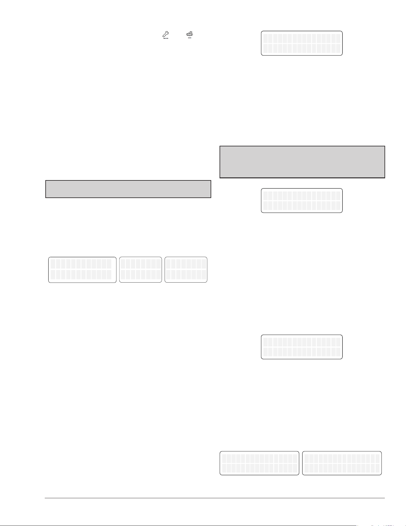
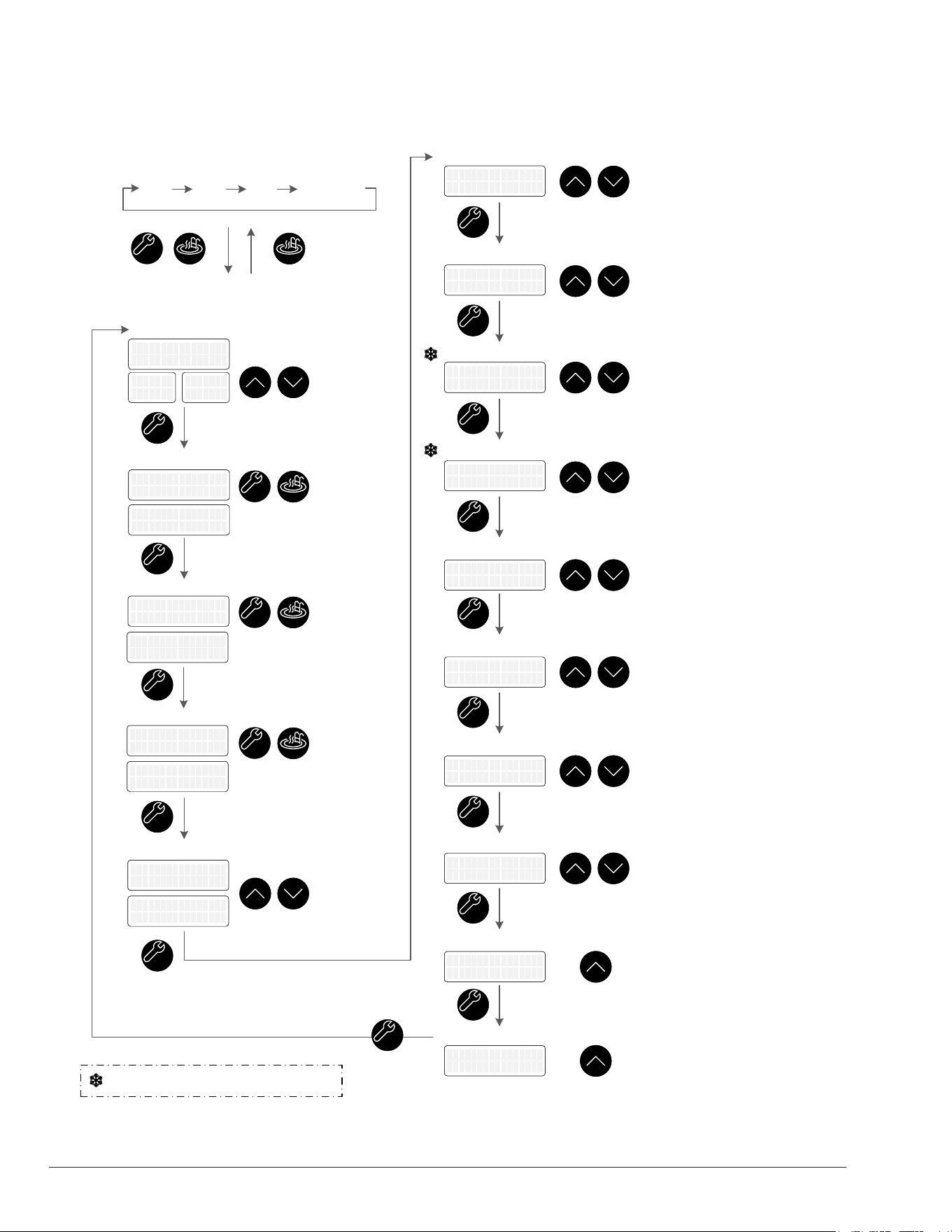
12. PROGRAM MENU ( + )
To access the PROGRAM menu, press and hold SERVICE
and MODE keys simultaneously for 10-seconds until
"Language" screen appears on the display.
This menu allows to change and reset the factory default
settings, as well as providing access to the Installers and
Schedule menus. There are different features and settings
required for different model types. This section outlines
the items noted on the display in Heat Only and Heat/Cool
congurations, the default values and range of adjustable
values and a description of the feature.
Any changes to values are stored into the non-volatile
memory after selection is made using the UP or DOWN
keys. Pressing SERVICE key toggles to the next setting.
Failure to press any key for 5-minutes will cause the screen
to return to Operation mode screen. The Program mode
can also be exited by pressing the MODE key.
CAUTION: Changes to default program congurations
could affect normal functionality of the heater.
Language Selection
The initial display in PROGRAM Menus is "Language"
selection.
The UP and DOWN keys will select English, Spanish or
French language for all menus and Display messages.
Language
English
Lenguaje
Español
Langue
Français
Figure 25. Language Selection Mode
Set Factory Defaults
Press the SERVICE key again. "Set Defaults" option
is displayed. To set factory defaults, press and hold
SERVICE and MODE keys simultaneously for 5-seconds
until "Defaults Set" appears. This operation resets the
operating program to its factory default values.
The pool setpoint is congured to 80°F (27°C), and the
SPA setpoints will default to 100°F (38°C). The maximum
temperature setting for pool and spa is limited to 95°F
(35°C) and 104°F (40°C), respectively. The language
is set to English, and the temperature display is set to
Fahrenheit. The cooling deadband is set to 6°F (3.5°C),
defrost temperature to 24°F (-4°C), defrost deadband
to 10°F (5.5°C) and outside lockout to 45°F (7°C),
respectively. The brownout is set to 230V, and the remote
pool mode is set to Heat. The local schedule is disabled
but not erased, and the "VS Pump Control" and other
add-ons are also disabled. Note that cooling deadband
and remote pool mode settings are only available in Heat/
Cool models.
The "Control Lockout PIN" will be cleared, and the control
will resume normal operation. See the "Control Lockout"
section on page 14.
Brownout Detect.
Set Defaults
Figure 26. Set Defaults Option
Reset Faults
Press the SERVICE key again. "Reset Faults" appears on
the digital display. To clear faults history, press and hold
SERVICE and MODE keys simultaneously for 5-seconds
until "Faults Cleared" appears.
This function clears the historical fault available in
SERVICE menu.
NOTE: When the unit is connected to Wi-Fi, the historical
faults can be accessed in the timeline tab of Raymote.
Reset faults do not affect historical faults registered in
Raymote.
Brownout Detect.
Reset Faults
Figure 27. Reset Faults Option
Wi-Fi Reset
Press the SERVICE key again. "Wi-Fi Reset" appears
on the digital display. To clear stored Wi-Fi signal name
and password, press and hold SERVICE and MODE
keys simultaneously for 5-seconds until "Wi-Fi Initialized"
appears.
This operation resets the Wi-Fi credentials, leaving the unit
ready to congure connection with the Raymote app. For
details on how to connect your pool heater to Raymote,
follow the instructions on page 45.
Brownout Detect.
WiFi Reset
Figure 28. Wi-Fi Reset Option
Temperature Display
Press the SERVICE key again "Temp Display" appears
on the digital display. The UP or DOWN keys will select
"Fahrenheit" or "Celsius" on the temperature display.
Choose the desired temperature scale. After making
the selection, all temperature screens will be updated to
display degrees in either Fahrenheit or Celsius.
Temp Display
Fahrenheit
Temp Display
Celsius
Figure 29. Temperature Display Option
18
Spa Setpoint Maximum Adjustment
Press the SERVICE key again. "Spa Max Temp" appears
on the digital display. Using the UP and DOWN keys will
change the maximum temperature setting to your desired
value. The control can be set to limit the maximum setpoint
in the range of 65°F to 104°F (18°C to 40°C). The default
value is 104°F (40°C).
Spa Max Temp
104F
Figure 30. Spa Setpoint Maximum Adjustment Option
Pool Setpoint Maximum Adjustment
Press the SERVICE key again. "Pool Max Temp" appears
on the digital display. Using the UP and DOWN keys will
change the maximum temperature setting to your desired
value. The control can be set to limit the maximum setpoint
in the range of 65°F to 95°F (18°C to 35°C). The default
value is 95°F (35°C).
Pool Max Temp
95 F
Figure 31. Pool Setpoint Maximum Adjustment Option
Cooling Deadband Adjustment -
(Heat/Cool Models Only)
Press the SERVICE key again. "Cooling Deadband"
appears on the digital display. Using the UP and DOWN
keys will change the cooling deadband setting. In POOL
AUTO mode, the cooling setpoint is the heating setpoint
minus this cooling deadband value. This setting can be set
in the range of 2°F to 10°F degrees (1°C to 5.5°C). The
default value is 6°F (3.5°C).
Cooling Deadband
6 F
Figure 32. Cooling Deadband Adjustment Option
Remote Pool Mode -
(Heat / Cool Models Only)
Press the SERVICE key again. "Remote Pool Mode"
appears on the digital display.
When Remote mode (3-wire selector) is enabled, and
the unit is a Heat/Cool model, this setting can be used to
dene the operation mode of the “Pool” wire selector. Use
UP and DOWN keys to set Remote pool mode to Pool
Heat, Pool Cool or Pool Auto. The default value for remote
pool mode is "Heat".
Remote Pool Mode
Heat
Figure 33. Remote Pool Mode Option
Defrost Temperature Adjustment
To adjust the defrost temperature, press the SERVICE
key and select "Defrost Temp" on the digital display. Use
the UP and DOWN keys to adjust the temperature setting,
which is measured on the coil during defrost mode. The
range of available settings is 20°F to 35°F (-6.5°C to
1.5°C), with a default value of 24°F (-4°C).
Defrost Temp
24F
Figure 34. Defrost Temperature Adjustment Option
Defrost Deadband Adjustment
To adjust the defrost deadband, press the SERVICE key
and select "Defrost Deadband" on the digital display. Use
the UP and DOWN keys to adjust the deadband setting,
which determines when defrost mode ends based on
the coil temperature. The defrost cycle ends when the
coil temperature is higher than the Defrost Temperature
plus the Defrost Deadband. You can set this value in the
range of 5°F to 20°F (2.5°C to 11°C), with a default value
of 10°F (5.5°C).
Defrost Deadband
10F
Figure 35. Defrost Deadband Adjustment Option
19
Outside Lockout Temperature
Adjustment
To adjust the outside lockout temperature limit, press
the SERVICE key and select "Outside Lockout" on the
digital display. Use the UP and DOWN keys to set the
ambient temperature at which the unit will be locked out
of operation. This setting can be adjusted in the range of
30°F to 50°F (-1°C to 10°C), with a default value of 45°F
(7°C).
Outside Lockout
45F
Figure 36. Outside Lockout Temperature Adjustment
Brownout Detection Mode
To adjust the brownout detection mode, press the
SERVICE key and navigate to "Brownout Detect" on the
digital display. You can then use the UP and DOWN keys
to choose from three options: 230V, 208V, or Disabled.
Enabling brownout detection will cause the unit to shut
down automatically if the Transformer's 24VAC signal
drops below a certain threshold, specically below
21VAC for 230V or below 24VAC for 208V. This function is
intended to protect the unit from low voltage situations. If
you prefer not to use this feature, simply select “Disabled”.
The default setting for brownout detection is 230V.
Brownout Detect.
230V
Figure 37. Brownout Detection Mode Option
Installer Menu
To access the Installer Menu, press the SERVICE key
and select "INSTALLER Menu" on the digital display. You
can use the UP key to enter the Installer menu, or press
SERVICE to move to the next option. For more details on
the "Installer Menu", please refer to page 21.
INSTALLER Menu
UP key to Enter
Figure 38. Installer Menu Option
Schedule Menu
To access the SCHEDULE Menu, press the SERVICE
key and select "SCHEDULE Menu" on the digital display.
You can use the UP key to enter the Schedule menu and
editor, or press SERVICE to return to the beginning of the
Program menu. For more information on the "Schedule
Menu", please refer to page 25.
SCHEDULE Menu
UP key to Enter
Figure 39. Schedule Menu Option
NOTE: Disabling "Brownout Detection" limits the ability
of the heater to protect the compressor.
20
Program Menu Diagram
Figure 40. Program Menu
+
10 sec
PROGRAM Menu
Set Defaults
Reset Faults
Temperature Display
Max Spa Setpoint
Max Pool Setpoint
WiFi Reset
OFF Pool Spa Timed Spa
Operation Mode
MODEMODE
SERVICESERVICE
MODEMODE
SERVICESERVICE
SERVICESERVICE
SERVICESERVICE
+
5 sec
SERVICESERVICE
Defaults SetDefaults Set
Faults ClearedFaults Cleared
Temp Display
Fahrenheit
Temp Display
Fahrenheit
Temp Display
Celsius
Temp Display
Celsius
Spa Max Temp
104 F
Spa Max Temp
104 F
Pool Max Temp
95 F
Pool Max Temp
95 F
WiFi ResetWiFi Reset
WiFi InitializedWiFi Initialized
Reset FaultsReset Faults
Set DefaultsSet DefaultsSet DefaultsSet DefaultsSet Defaults
Language
SERVICESERVICE
Language
English
Language
English
Lenguaje
Español
Lenguaje
Español
Langue
Français
Langue
Français
SERVICESERVICE
Select
Display
Language
UPUP
DOWNDOWN
MODEMODE
SERVICESERVICE
Set Factory
Defaults
+
5 sec
MODEMODE
SERVICESERVICE
Reset Fault
History
+
5 sec
MODEMODE
SERVICESERVICE
Clear Wi-Fi
Configuration
Select
Temperature
Scale
UPUP
DOWNDOWN
Adjust Spa
Temperature
Limit
UPUP
DOWNDOWN
Cooling Deadband
SERVICESERVICE
Cooling Deadband
6 F
Cooling Deadband
6 F
Remote Pool Mode
Remote Pool Mode
Heat
Remote Pool Mode
Heat
Select
Remote Pool
Operation
UPUP
DOWNDOWN
SERVICESERVICE
65°F - 104°F
Adjust Spa
Temperature
Limit
UPUP
DOWNDOWN
65°F - 95°F
Adjust
Cooling
Deadband
UPUP
DOWNDOWN
2°F - 10°F
Defrost Temperature
SERVICESERVICE
Defrost Temp
24 F
Defrost Temp
24 F
Adjust
Defrost
Temperature
UPUP
DOWNDOWN
20°F - 35°F
Defrost Deadband
SERVICESERVICE
Defrost Deadband
10 F
Defrost Deadband
10 F
Adjust
Defrost
Deadband
UPUP
DOWNDOWN
5°F - 20°F
Outside Lockout
SERVICESERVICE
Outside Lockout
45 F
Outside Lockout
45 F
Adjust Outside
Lockout Temp.
UPUP
DOWNDOWN
30°F - 50°F
Heat, Cool
or Auto
Brownout Detection
SERVICESERVICE
Brownout Detect.
230V
Brownout Detect.
230V
Select
Brownout
voltage option
UPUP
DOWNDOWN
230v, 208v
or Disabled
Installer Menu
SERVICESERVICE
INSTALLER Menu
UP key to Enter
INSTALLER Menu
UP key to Enter
Press UP key to
enter Installer
Menu
UPUP
Schedule Menu
SERVICESERVICE
SCHEDULE Menu
UP key to Enter
SCHEDULE Menu
UP key to Enter
Press UP key to
enter Schedule
Menu
UPUP
SERVICESERVICE
Options available only in Heat/Cool models
21
13. INSTALLER MENU
The Installer menu shows the options to control external
devices like pumps, valves, and auxiliaries, directly from
the heat pump built-in scheduler or Online Raymote
automation.
"Installer Menu" can be accessed from the program
menu. Use the UP key to enter in the Installers menu or
press SERVICE to skip to the next option.
• Use the SERVICE key to move along the options of
the Installer menu.
• Use the UP and DOWN keys in each screen to adjust
and select operation modes and settings.
• Use MODE key to return to the "Program Menu".
Auxiliary Output 1 & 2 Operation
Modes
When entering the INSTALLER menus, the displays
will show "Auxiliary 1 mode" and "Auxiliary 2 mode." On
each screen, you can choose an operation mode using
the UP and DOWN keys. These modes include:
• Raymote: which allows Wi-Fi control using Raymote
online automation.
• Schedule: which allows the heat pump built-in clock
and schedule to control the auxiliary.
• Auxiliary Heat: which congures the auxiliary to
turn on an external heater. The control will turn on the
auxiliary automatically if the water temperature is 10°F
lower than the pool or spa heat setpoint. The unit will
turn off the auxiliary when heat demand is satised.
The default value for the 'Auxiliary 1' and 'Auxiliary 2'
operation modes is the Raymote mode.
For details regarding auxiliary wiring, refer to section 27,
"Optional Control Outputs", on page 73.
Auxiliary 1 mode
Raymote
Auxiliary 2 mode
Raymote
Figure 41. Auxiliary Output Operation Modes
Single-Speed Pump Operation Mode
To access the "Single-Speed Pump" operation mode,
press the SERVICE key again, and the digital display
will show "Single-Speed Pump." To select an operation
mode, use the UP and DOWN keys and choose from the
following options:
• Raymote: The single-speed pump output is set to be
controlled from Wi-Fi with Raymote online automation.
• Schedule: The single-speed pump output is set
to be controlled by the heat pump built-in clock and
schedule.
• Heater Demand: The single-speed pump output
is set to turn on when the heater starts the heating
or cooling operation. The unit turns the single-speed
pump output off when heat demand is satised.
The default value for single-speed pump output operation
mode is "Disabled". This function can be used with the
control board terminal P5 labeled as "PUMP." For details
about single-speed pump wiring, refer to section 27,
"Optional Control Outputs", on page 73.
Single Speed Pump
Disabled
Single Speed Pump
Raymote
Figure 42. Single-Speed Pump Operation Mode
Variable-Speed Pump Operation Mode
When you press the SERVICE key again, the digital
display will show "VS Pump Control." To select an
operation mode, use the UP and DOWN keys and choose
from the following options:
• Disabled: The Variable-Speed Pump functions are
disabled, and no commands are sent to the external
pump.
• Protégé VSP: The heater uses a 4-pin terminal P12
labeled as “COM” to command an external Raypak
Protégé Variable-Speed Pump.
• 4-Speed Control: The heater's 4-speed control is
achieved by using the 5-pin digital outputs located in
the terminal P8 labeled "VAR PUMP" to command an
external variable-speed pump that is compatible with
30V DC signals supplied by the heater.
By default, the variable-speed pump output operation
mode is set to "Disabled". For more information about the
wiring of the variable-speed pump, refer to section 27,
"Optional Control Outputs", on page 73.
VS Pump Control
4-Speed Control
VSP Control Mode
Heater Demand
Pump Heat Speed
3
Figure 43. Variable-Speed Pump Operation Mode

22
When the variable-speed pump control is enabled, the
menu "VSP Control mode" becomes available. Use the
UP and DOWN keys to choose from the following options:
•Raymote: which allows Wi-Fi control using Raymote
online automation.
•Schedule: which allows the heat pump built-in clock
and schedule to control the variable-speed pump.
•Heater Demand: The variable-speed pump output is
set to turn on when the heater starts the heating or
cooling operation. The unit commands the variable-
speed pump output per the setting selection in the
Pump Heat Speed screen.
Valves Control
Press the SERVICE key again to access the "Valves
Operation" menu, where you can select the operation
mode of the valve control outputs. By default, this function
is disabled. Use the UP and DOWN keys to choose from
the following options:
• Raymote: which allows Wi-Fi control using Raymote
online automation.
• Pool-Spa: which congures the valve actuator
outputs to be commanded automatically when Pool or
Spa mode is set in the heater.
By default, the valve control mode is set to "Raymote". For
more information about the wiring of the valve outputs,
please refer to section "27. EXTERNAL CONTROL
OUTPUTS" on page 73.
Valves Control
Raymote
Figure 44. 3-Way Valve Control
Valves Outputs Position Selection
Press the SERVICE key again. When "Valves Control"
mode is set to "Pool-Spa", you'll see the "Valve 1" and
"Valve 2" options on the digital display. This function
uses the "VALVE 1" and "VALVE 2" terminals of the
control board. To associate Valve 1 and Valve 2 with the
"Position 1" of either the pool or spa operation mode, use
the UP and DOWN keys on the control panel. For more
information on valve control output wiring, please refer to
section "27. EXTERNAL CONTROL OUTPUTS" on page
73.
Suction Valve
Position 1 = Pool
Return Valve
Position 1 = Pool
Figure 45. Valve 1 and 2 Outputs Position Selection
Solar Heating Integration
(Heat/Cool Models Only)
To access the "Solar Heating" function, press the
SERVICE key again. The digital display will show "Solar
Heating". By default, this feature is disabled. You can
use the UP and DOWN keys to enable or disable solar
heating integration.
When enabled, the controller will monitor the temperature
of a eld-supplied 10K temperature sensor connected in
the input terminal P11. The controller adjust the position
of the solar 3-way valve connected to terminal P9, to
deliver water either to the solar heater or the heat pump.
See section 27, page 84, for details regarding Solar
Heating integration.
When Solar Heater is enabled, the heat pump commands
the solar 3-way valve (P9) to direct the ow from the
ltration system to the solar heater and nally to the heat
pump. This operation mode works only during day time
hours 8:00 a.m. to 5:00 p.m. When the unit is connected
to Raymote the daytime hours are automatically set by
the estimated location of the heater.
The Solar heater integration works as follows:
• The solar 3-way valve is set to deliver hot water from
the solar heater for a laps of 3-minutes minimum.
• If the water temperature of the solar heater is 3°F
(1.5°C) above pool water temp, the solar 3-way valve
remains active delivering water from the solar heater.
• The solar valve is set to "heat pump" position when
demand for heat is satised or when the solar
temperature is less than 3°F (1.5°C) in comparison
with pool water temperature.
• When solar temperature is less than 3°F (1.5°C), and
heat demand is active, the heat pump will command
the solar 3-way valve to close, bypassing the solar
collector and passing water directly to the Heat
Pump. If demand for heat prevails after 2-hours, the
solar valve is opened again to test the temperature in
the solar heater.
• The heat pump will work simultaneously with the
solar heater until the heat demand is satised.
Solar Heating
Disabled
Figure 46. Solar Heating Integration
When Solar Heater is enabled, the solar sensor is
considered the inlet water sensor for the system.
The following parameters can be adjusted when solar
heater is enabled:
• Solar 3-way valve position selection
• Solar heater temperature limit
• Solar heater retry time
• Solar deadband

23
The following paragraphs describe the functionality of
each parameter. For more information on Solar heater
integration and wiring, please refer to section "27.
EXTERNAL CONTROL OUTPUTS" on page 73.
Solar Valve Position Selection
(Heat/Cool Models Only)
To access the "Solar Valve" position selection, press the
SERVICE key again. When the "Solar Heating" option is
enabled, the "Solar Valve" option will appear on the digital
display. The "Solar Valve" option uses the 3-pin terminal
P9 labeled as "SOLAR". Use the UP and DOWN keys
to associate the Solar valve "Position 1" to either "Heat
Pump" or "Solar Heater". For more information about the
solar valve sensor wiring, please refer to section "27.
EXTERNAL CONTROL OUTPUTS" on page 73.
Solar Valve
Pos1 = Heat Pump
Figure 47. Solar Valve Selection
Solar Heater Temperature
(Heat/Cool Models Only)
Press SERVICE again to access the "Solar Delta" setting.
This setting determines the minimum water temperature
delivered by the solar heater to keep the solar 3-way
valve directing ow to the solar heater. Use the UP and
DOWN keys to adjust this parameter from 0°F to 10°F
(0°C to 5.5°C). The default value is 3°F (1.5°C).
When this setting is set to 0°F (0°C), the solar 3-way valve
remains active as long as the water delivered by the solar
heater is not losing heat.
Solar Delta
3 F
Solar Delta
3 F
Figure 48. Solar Delta Selection
Solar and HPPH Deadband
(Heat/Cool Models Only)
Press SERVICE again to access the "Solar Deadband"
setting. This setting determines the temperature limit
of the heat pump operation while the solar heater is
supplying hot water. Use the UP and DOWN keys to
adjust this parameter from 0°F to 20°F (0°C to 11°C). The
default value is 0°F.
When this setting is set to 0°F, the heat pump operation
remains active until the demand for heat is satised. For
example, if the Solar deadband is set to 5°F, the heat
pump keeps heating until the water temperature sensed by
the solar sensor is 5°F or less from the water temperature
setpoint. To give priority to the solar heater, set the solar
deadband to 20°F (11°C).
Solar Deadband
0 F
Solar Deadband
0 F
Figure 49. Solar Deadband Selection
Solar Heater Retry Time
(Heat/Cool Models Only)
Press SERVICE again to access the "Solar Retry Time"
setting. This setting determines the period of time to
check again the solar heater delivery. Use the UP and
DOWN keys to adjust this parameter from 2 to 4 hours.
The default value is 2-hours.
This setting is used when the solar heater water
temperature is below the solar limit (Solar delta). In this
case, the heat pump controller uses this time to retry
using the solar heater.
Solar Retry Time
2 Hours
Solar Retry Time
2 Hours
Figure 50. Solar Retry Time
For more information on Solar heater integration and
wiring, please refer to section "27. EXTERNAL CONTROL
OUTPUTS" on page 73.
Auxiliary Input
Press the SERVICE key once again to access the
"Auxiliary Input" menu, where you can enable and choose
the functionality of an optional Auxiliary input. By default,
this feature is disabled. Use the UP and DOWN keys to
select from the following options:
• Disabled: The input is disregarded.
• Warning: The Fault "Aux Input Warning" is shown in
the LCD and Raymote if the auxiliary input in terminal
P11 is open. The unit continues its operation, but the
fault is reported and recorded in the fault history.
• Interlock: The Fault/interlock "Aux Input Fault" is
displayed in the LCD and Raymote. The operation of
the heater is prevented or terminated until Input P11
is closed again.
Auxiliary Input
Disabled
Figure 51. Auxiliary Input
For more information about the Auxiliary input wiring,
please refer to section "27. EXTERNAL CONTROL
OUTPUTS" on page 73.
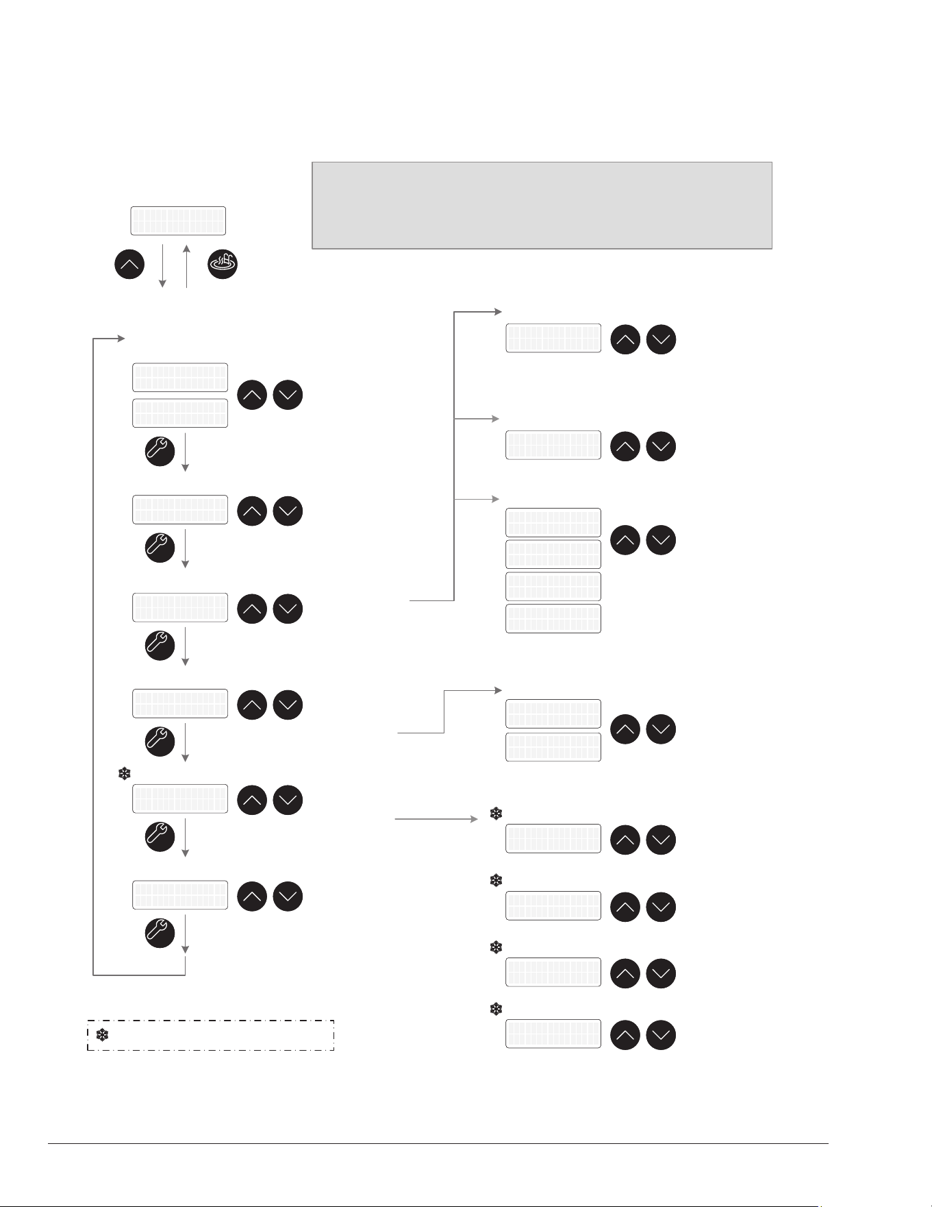
24
Installer Menu Diagram
Figure 52. Installer Menu
INSTALLER Menu
MODEMODE
Auxiliary 1 and 2
Operation mode
SERVICESERVICE
Auxiliary 1 mode
Raymote
Auxiliary 1 mode
Raymote
UPUP
DOWNDOWN
INSTALLER Menu
UP key to Enter
INSTALLER Menu
UP key to Enter
UPUP
Select mode:
• Raymote
•
Schedule
• Auxiliary
Heat
Auxiliary 2 mode
Raymote
Auxiliary 2 mode
Raymote
SERVICESERVICE
UPUP
DOWNDOWN
Select mode:
• Raymote
• Schedule
• Heater
Demand
Single Speed Pump
Disabled
Single Speed Pump
Raymote
SERVICESERVICE
UPUP
DOWNDOWN
Select mode:
• Disabled
• 4-Speed Control
• Protégé VSP
VS Pump Control
Disabled
VS Pump Control
Disabled
Single Speed Pump
Variable Speed Pump
SERVICESERVICE
UPUP
DOWNDOWN
Select mode:
• Raymote
• Pool-Spa
Valves Operation
Disabled
Valves Operation
Raymote
Valves Control
SERVICESERVICE
UPUP
DOWNDOWN
Select mode:
• Disabled
• Enabled
Solar Heater
Disabled
Solar Heater
Disabled
Solar Heater
SERVICESERVICE
UPUP
DOWNDOWN
Auxiliary Input
Disabled
Auxiliary Input
Disabled
Auxiliary Input
Select mode:
• Disabled
• Warning
• Interlock
UPUP
DOWNDOWN
Select Speed:
1 - 4
Pump Heat Speed
3
Pump Heat Speed
3
Pump - Heat Speed [#]
UPUP
DOWNDOWN
Set Speeds:
900 - 3400 RPM
Pump Speed 1
900 RPM
Pump Speed 1
900 RPM
Protégé Speed 1-4 [RPM]
UPUP
DOWNDOWN
Position 1:
Pool or Spa
Valve 1
Position 1 = Pool
Valve 1
Position 1 = Pool
Valves Position
Pump Speed 2
1500 RPM
Pump Speed 2
1500 RPM
Pump Speed 3
2500 RPM
Pump Speed 3
2500 RPM
Pump Speed 4
2900 RPM
Pump Speed 4
2900 RPM
UPUP
DOWNDOWN
Solar Valve
Pos1 = Heat Pump
Solar Valve
Pos1 = Heat Pump
Solar Valve
Position 1:
Heat Pump or
Solar Heater
Valve 2
Position 1 = Pool
Valve 2
Position 1 = Pool
INSTALLER MENU OPTIONS
The Installer menu shows the options to control external devices
directly from the Heat Pump built-in scheduler or from Raymote app
online automation.
UPUP
DOWNDOWN
VSP Control Mode
Raymote
VSP Control Mode
Raymote
VSP Control mode
Select mode:
• Raymote
• Schedule
• Heater
Demand
UPUP
DOWNDOWN
Solar Delta
3 F
Solar Delta
3 F
Minimum Solar Delivery
Set Solar limit :
0°F - 10°F
UPUP
DOWNDOWN
Solar Deadband
0 F
Solar Deadband
0 F
Solar Deadband
Set Deadband:
0°F - 10°F
UPUP
DOWNDOWN
Solar Retry Time
2 Hours
Solar Retry Time
2 Hours
Solar Timeout
Set Timeout:
2 - 4 Hours
Options available only in Heat/Cool models

25
14. SCHEDULE MENU
NOTE: The Schedule menu can be used to congure
automatic control of external devices directly from the
Heat Pump built-in scheduler. By default, internal control
is set to “Raymote” Wi-Fi control. To control external
devices with the built-in schedule, use the Installer
menu to congure control mode of the external devices
to “Schedule mode”.
The schedule menu shows the options to congure the
heat pump built-in scheduler. See Figure 54. This local
schedule works with the built-in clock and allows the user
to run up to 4-events per day, like controlling pumps,
auxiliary outputs, and operation mode automatically from
the heat pump control board.
The schedule menu can be accessed from the Program
menu.
• Use the SERVICE key to move along the options of
the Schedule menu.
• Use the UP and DOWN keys in each screen to adjust
and select number of events, start time, operation
modes and other programmable settings.
• Use MODE key to return to the Program menu.
• To set times faster, press and hold UP or DOWN
keys.
Set Current Time
Press the SERVICE key again. "Set Current Time" option is
displayed only when the heater is not connected to Wi-Fi.
The control has a 24-hour time clock. This option allows
setting of the current time. The time is followed by A.M. or
P.M. When the unit is connected to Wi-Fi, the clock is set
automatically.
Use the UP and DOWN keys to adjust the clock's time.
Holding the UP or DOWN key accelerates the change in
the numbers of the clock. Press the SERVICE key when
completed to save the changes.
The time clock is used to run the events dened in the built-in
schedule. Please refer to INSTALLER menu on page 21
to congure external devices like pumps, and auxiliaries.
Set Current Time
09:09 PM
Figure 53. Set Time Option
Set Time with Raymote
When the heater is connected to Wi-Fi, the clock will be
updated by Raymote.
Make sure to use the correct Time zone and Location in
the Raymote heater settings or Raymote organization
settings.
The Time zone can be congured while connecting the unit
to Wi-Fi or at any other time while the unit is connected to
the Internet.
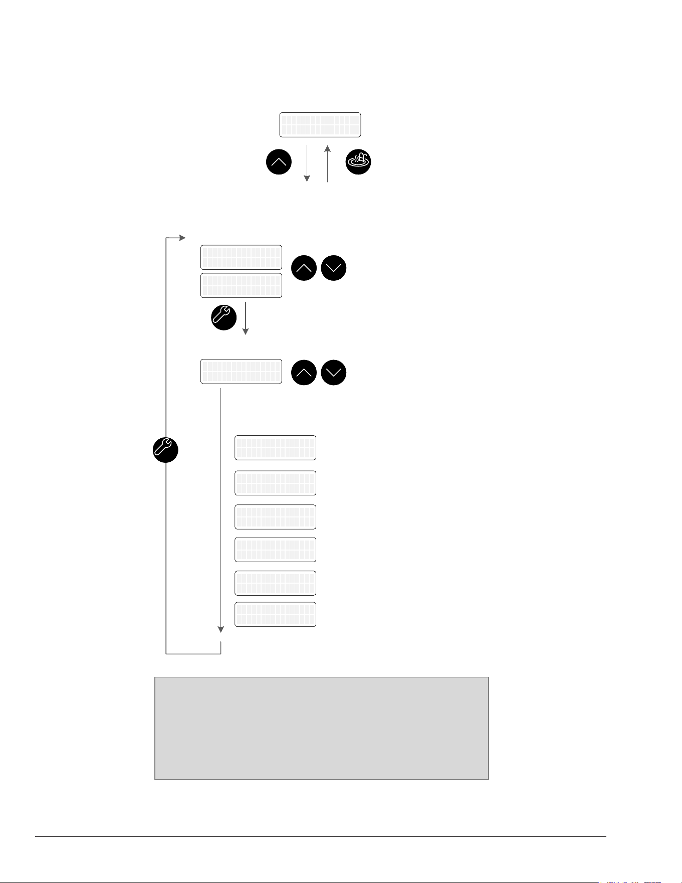
26
SCHEDULE Menu
MODEMODE
SCHEDULE Menu
UP key to Enter
SCHEDULE Menu
UP key to Enter
UPUP
UPUP
DOWNDOWN
Events per Day
1
Events per Day
1
Schedule Events
Set Current Time*
Set Current Time
09:09 AM
Set Current Time
09:09 AM
Set DefaultsSet Current Time
12:01 AM
Set Current Time
12:01 AM
Set DefaultsSet Current Time
12:01 AM
Adjust Current Time:
12:00 AM to 11:59 PM
*This screen is not
displayed when unit is
connected to Wi-Fi
UPUP
DOWNDOWN
Events selection:
0 to 4.
E1 VS Pump Speed
No Change
E1 VS Pump Speed
No Change
Events 1 to 4 Setup
E1 Start time
8:00 AM
E1 Start time
8:00 AM
E1 1-Speed Pump
No Change
E1 1-Speed Pump
No Change
E1 Auxiliary 1
No Change
E1 Auxiliary 1
No Change
E1 Auxiliary 2
No Change
E1 Auxiliary 2
No Change
Set Variable Speed Pump to:
Speed 1 to 4, Off or No Change
Set Start Time: 12:00 AM to
11:59 PM
Set Single Speed pump: On, Off
or No Change
Set Auxiliary 1 to: On, Off or No
Change
Set Auxiliary 2 to: On, Off or No
Change
E1 OperationMode
No Change
E1 OperationMode
No Change
Set Operation: Pool Heat, Pool
Cool*, Pool Auto*, Spa, Off or
No Change
SERVICESERVICE
SERVICESERVICE
Example:
Each Event executes a set of commands defined by the
user. For example, if the single speed pump output needs to
be turned on at 8:00 AM and turned off at 2:00 PM:
- Set “E1 start time” to 8:00 AM and “1-Speed Pump” to On.
- Set “E2 start time” to 2:00 PM and “1-Speed Pump” to Off.
Figure 54. Schedule Menu
Schedule Menu Diagram

27
15. DIGITAL CONTROLS
OPERATION
Your heat pump pool heater incorporates digital safety
controls and indicators to ensure safe and reliable
operation. The pool water temperature is controlled by
the heater's digital control system, which provides multiple
operation modes as described in section 10, "Operation
Modes," on page 12.
Furthermore, the unit is compatible with most "2-wire" and
"3-wire" control/automation systems. For more information
about 2 and 3-wire control, refer to section 16, "Remote
Mode Selector", on page 32.
This section explains the general control sequence of
operation, as well as the protections provided by the
heater to ensure safe and dependable operation.
Sequence of Operation
1. Upon the initial application of power, the heater
control briefly illuminates all segments on the LCD
at power-up.
2. The control displays the current software version
on the LCD for 2-seconds, then resumes the user-
selected mode it was in before power was interrupted.
3. If the unit type has not been set, the control prompts
the user to set the model type before enabling any
device operation.
NOTE: The model is set from the factory. If the model
needs to be updated due to a board replacement, use
the special menu "Model Type", available in the Installer
menu. The Installer menu can be accessed from the
Program menu. Refer to section 13, "Installer Menu", on
page 21 for more information.
4. Optional: During the initial operation, there are
several optional items that can be defined and
programmed depending on the intended configuration
and accessories to be controlled by the heater.
These include control of valves, single-speed and
variable-speed pumps, and auxiliary outputs. Once
these options are selected, further information is
required to establish the pump periods, pump speed
during each period, and auxiliary outputs command
for each period, which must be determined and set
in the SCHEDULE menu for local automation or with
Raymote app for remote control with Wi-Fi. Once
programming is completed, the heater control is
ready for operation.
NOTE: Optional control items are not enabled by
default at the factory. To activate and congure these
features, please refer to the "Installer" and "Schedule"
menus. Both menus are accessible from the Program
menu. Refer to section 13, "Installer Menu", on page
21 and section 14, "Schedule Menu", on page 25,
for more information.
5. The user can select one of several operating modes
depending on the unit type. To cycle between
the modes, simply press the MODE key. Each
press of the MODE key selects the next mode.
• For Heat Only models, the available mode
selections are OFF, POOL, SPA, and TIMED SPA.
• For Heat/Cool models, the available mode
selections are OFF, POOL COOL, POOL
HEAT, POOL AUTO, SPA, and TIMED SPA.
For more information, refer to section 10, "Operation
Modes", on page 12. For information about the
remote mode, please refer to section 16, "Remote
Mode Selector", on page 32.
6. During operation, the unit will run until the water
temperature reaches 0.5°F (0.3°C) above the
setpoint for heating (or below for cooling), or until the
unit is manually turned off.
7. The unit will enter standby mode and wait for the
next demand to start heating or cooling the water.
System Start-Up
1. Ensure that the Digital Board is displaying the correct
temperature and that the pool pump is running, and
water is circulating properly.
2. Confirm that the Board is programmed with the
desired temperature setpoint for the pool and/or spa.
3. Allow the heater to operate for a few minutes to
stabilize the operating pressures and allow various
component temperatures to normalize.
4. After the unit has been operating in heating mode
for a few minutes, check that the discharge air
temperature is approximately 8°F-10°F (4.4°C-5.5°C)
cooler than the air entering the unit.
5. In Heat/Cool models, after the unit has been operating
in cooling mode for a few minutes, the discharge
air temperature should be 8°F-10°F (4.4°C-5.5°C)
warmer than the air entering the unit.
NOTE: Heating is more efcient during warmer daylight
hours, while cooling is more efcient during cooler
nighttime hours. To speed up the cooling process, turn
off the pool/spa blanket and turn on any fountains,
sprays, or other water features at nighttime.
28
Operational Status Messages
The LCD screen displays a range of status and diagnostic messages, depending on the operating conditions. The
following status messages, will be shown in pool, spa, and remote modes when no active fault conditions are present.
Table D. Operational Status Messages
Display Condition
No Demand
Demand has been satised and the unit is in standby.
Heating
Unit is operating and running a heating cycle.
Cooling
Unit is operating and running a cooling cycle.
Defrost
Unit is performing a defrost cycle. Coil temperature is below defrost temperature limit. Verify defrost
temperature and defrost deadband settings.
Comp Start Delay Notication that the compressor is under a 3-minute delay before turning on.
Valve Chng Delay
Notication that the 3-way valves are being commanded to change positions
pool to spa, or spa to pool.
Solar Heat
The solar heating setting is enabled, and running with the heat pump.
Outside Lockout
The compressor is not running because the ambient temperature is too cold as measured by the
ambient sensor. Verify outside lockout temperature setting.

29
Error Messages
The following error messages are displayed in pool, spa, and remote modes. Consecutive identical faults are only
stored once in the "Fault History".
A
WARNING: Performing service on this equipment requires specialized expertise, mechanical skills, tools, and
equipment. If you do not possess these, it is not recommended to attempt any service on this equipment unless
following the procedures outlined in this manual.
Display Troubleshooting
In Sensor Fault Inlet sensor fault - Check for low water ow conditions. Check pump speed. Check inlet sensor.
In Sensor Open Inlet sensor fault - Sensor open. Check sensor wires and harness terminals.
In Sensor Short Inlet sensor fault - Sensor short. Check sensor wires and terminals.
Out Sensor Open Outlet sensor open - Check sensor wires and terminals.
Out Sensor Short Outlet sensor shorted - Check sensor wires and terminals.
Amb. Sensor Open Ambient temperature sensor open - Check sensor wires and terminals.
Amb. Sensor Shrt Ambient temperature sensor shorted - Check sensor wires and terminals.
Flow Sensor Fail Flow sensor fault - Readings out of range. Check ow sensor settings.
Check Pump Fault Pump controller faulted - Check that pump controller status. Check conguration.
Coil Sensor Open Coil sensor open - Check sensor wires and terminals.
Coil Sensor Short Coil sensor short - Check sensor wires and terminals.
Pump Ctl Fail
Protégé pump is not responding - Check that pump is powered and connected. Check variable-speed
pump settings.
Sensor Misplaced Water inlet temperature is higher than outlet temperature while heating. Check sensors installation.
Internal Fault Controller faulted - Memory corrupted. Power cycle unit. Replace main board.
Low Temp Lockout
Temperature lockout - Water temperature below is 36°F (2°C). Check water temperature. Check inlet
sensor.
Hi Press Trip High-pressure switch tripped - Check water ow, check refrigerant load.
Lo Press Trip Low-pressure switch tripped - Check refrigerant load.
Hi Press Lockout High-pressure lockout - Multiple pressure trips detected. Check refrigerant load.
Lo Press Lockout Low-pressure lockout - Multiple pressure trips detected. Check refrigerant load.
Brownout Low voltage in 24V transformer - Check voltage input 230v /208v.
Clock Fault Real time clock fault - Unable to read or set clock.
Hi Water Trip High-temperature water trip - Inlet water is higher than 106°F (41°C).
Hi Water Lockout High-temperature water lockout - Inlet water is higher than 108°F (42°C).
Remote Error Remote 3-wire selector fault - Pool and spa inputs are energized. Check 3-wire remote control terminals.
Water PS Open Water pressure switch open - Check pump operation. Check water ow.
Outside Lockout Outside lockout - Compressor not running because ambient too cold.
Hi Delta-T High delta temperature between inlet and outlet. Check water ow. Check pump operation.
Heating Fail Outlet temperature not higher than inlet temperature. Check compressor.
Cooling Fail Outlet temperature not lower than inlet temperature. Check reversing valve.
Solar Sensor Open Solar sensor open - Check sensor wires and terminals.
Solar Sensor Short Soar sensor short - Check sensor wires and terminals.
Defrost Lockout Defrost operation not effective. Conrm ambient conditions.
Aux Input Warning Auxiliary input is open - Check heater. Check wiring and conguration of auxiliary input.
Aux Input Fault Auxiliary input is open - Check heater. Check wiring and conguration of auxiliary input.
No Communication
with Heat Pump
Communication harness between Main board and Keypad may be damaged or disconnected. Check wires
or replace harness.
Table E. Error Messages
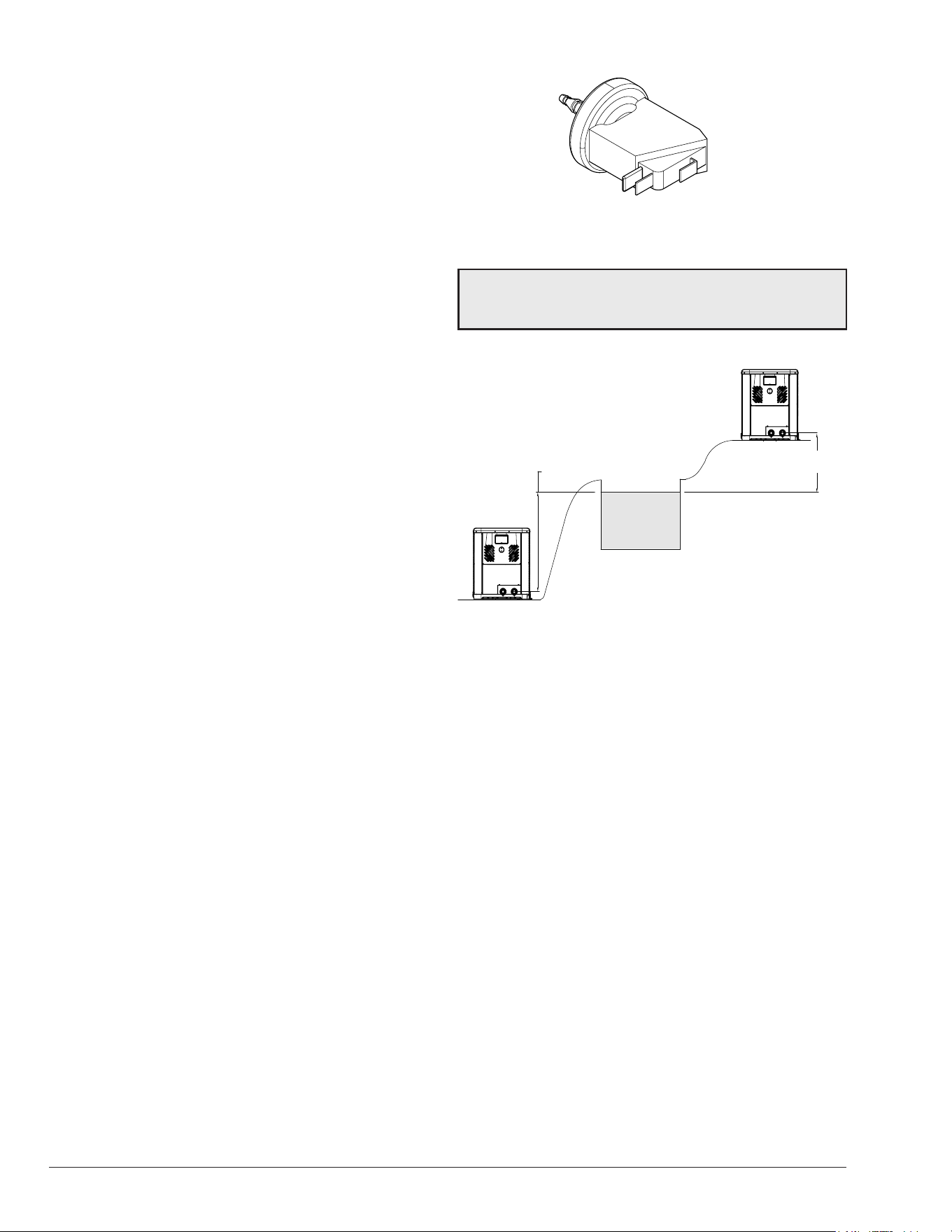
30
Minimum Run Time
To ensure the compressor operates efciently and has a
longer lifespan, the control has set a minimum run time of
3-minutes. If the setpoint temperature is reached within
3-minutes, the compressor will continue to run for the
remaining time, unless one of the following conditions
occur: (1) the high-pressure switch is tripped, (2) the
water-pressure switch is tripped, (3) the high-temperature
limit is reached, or (4) the user selects the "OFF" mode.
Compressor Start Delay
To prevent the compressor from short cycling, the control
is programmed with a compressor start delay. The
compressor will not be energized unless it has been off
for at least 3-minutes. During this delay, the display will
show "Comp Start Delay", until the 3-minute wait time is
completed and the compressor starts.
Water Pressure Switch
The control system includes a water pressure switch (or
ow switch, if available) that is constantly monitored. If
the compressor is required and the water pressure switch
is open, the control system will prevent the compressor
from starting and display the message "Water PS Open"
on the screen.
The water pressure switch ensures that the heater
operates only when the lter pump is in operation. It is
located on the In/Out header. It is factory-set at 1.75 PSI
for deck level installation.
Water Pressure Switch Adjustment
When the heater is located below the level of the spa or
pool, it may be necessary to adjust the pressure switch to
compensate for the no-ow static head. If it is necessary
to adjust the water pressure switch, do the following:
1. Make sure the pool filter is clean before adjusting the
switch.
2. Set the heater control to the OFF mode.
3. Turn the filter pump ON and confirm that the pressure
switch is closed (use a multimeter to check). If the
pressure switch fails to close, either the switch setting
is too high or not enough pressure is being supplied
by the filter pump.
4. Turn the heater ON.
5. Manually turn the pressure adjustment knob clockwise
until the heater shuts off. (A flat screwdriver may be
necessary if knob is too tight.)
6. Slowly turn the adjustment knob counter-clockwise
until the heater calls-for-heat again.
7. Turn an additional 1/2 turn counter-clockwise.
8. While the heater is running, check the adjustment
by turning the pump off and on several times. The
burners should shut off immediately when the pump
is turned off. If it does not, repeat the above steps
until proper operation is observed.
H000025
Figure 55. Water Pressure Switch
NOTE: The sheet metal access panels should be in
place at all times to protect the water pressure switch
from rain and other environmental factors.
5 ft. (1.52 m) MAX
POOL OR SPA
5 ft. (1.52 m)
MAX
MAY REQUIRE ADJUSTMENT
FOR HIGHER PRESSURE
MAY REQUIRE ADJUSTMENT
FOR LOWER PRESSURE
Figure 56. Pressure Switch Adjustment Requirements
Defrost Operation
The control's defrost temperature limits vary depending on
the unit's conguration, whether it is a Heat Only or a Heat/
Cool unit.
The control initiates a defrost cycle when the coil
temperature falls to the "Defrost Temp" limit established
in the Program menu, which is 24°F (-4°C) by default. For
Heat Only models, during the defrost cycle, the compressor
will shut off, while the fan will continue to operate to pull
warmer air across the coil for defrosting.
For Heat/Cool models, during the defrost cycle, the control
shuts off the fan and activates the reversing valve, while
the compressor remains running. This action directs the
hot refrigerant gas to the coil for defrosting.
Once the control sees a rise in the coil sensor temperature
equal to "Defrost Temp" + "Defrost Deadband", which is
10°F (-12°C) by default, or after 15-minutes have passed,
the unit exits the defrost cycle and returns to normal
heating operation based on the current water temperature
and setpoint temperature.

31
Low Ambient Temperature
- Outside Lockout
The control features a Low Ambient Temperature Lockout
function that prevents operation when the ambient
temperature falls below the "Outside Lockout" temperature
limit. You can access this setting through the Program
menu, and the default value is 45°F (7°C). However, the
temperature limit is adjustable, and you can set it between
30°F (-1°C) and 50°F (10°C) according to your needs.
High Water Temperature Limit
If the compressor is demanded and the inlet water
temperature is 106°F (41°C) or higher, the control will
prevent compressor start, allow the pump to run, and show
"Hi Water Trip" on the second line of the LCD. The fault
is removed only when the water temperature drops below
106°F (41°C).
In the event that the inlet water temperature sensor reads
at or above 108°F (42°C) while the compressor is running,
the control will shut down the compressors and display
"Hi Water Lockout" on the second line of the LCD. The
compressors will remain locked out until the inlet sensor
reading falls below 103°F (39°C).
This high-temperature limit is active in all modes of
operation, including cooling operation (heat/cool models),
in case of a reversing valve failure. High water temperature
is ignored if there is no demand for the compressor.
High-Pressure Switch Lockout
In the event that the high-pressure switch opens, the
control turns off the compressor output, and the fan will
continue to operate for 15-minutes after the High-Pressure
Switch (HPS) opens. Additionally, the display will show "Hi
Press Trip."
If the high-pressure switch trips 7-times within a single
cycle, the display will show "Hi Press Lockout," and the
unit will be disabled for 4-hours. The unit will automatically
reset after 4-hours, or the lockout can be manually reset by
pressing the MODE key or by power cycling. It is important
to note that the high-pressure switch must remain closed
for a minimum of three-seconds for the control to recognize
that it has closed.
Low-Pressure Switch Lockout
The control has a 30-second grace period after the
compressor is energized during which it will ignore an open
low-pressure switch. However, if the low-pressure switch
remains open for 3 or more seconds after this period, the
compressor will shut down and the display will show "Lo
Press Trip".
In the event that the low-pressure switch trips 6-times
within a single cycle, the control will display "Lo Press
Lockout" and the unit will be disabled for 4-hours. After the
4-hour period has elapsed, the unit will automatically reset.
Alternatively, the lockout can be manually reset by power
cycling the unit. It's important to note that the low-pressure
switch must be closed for at least 3-seconds in order for
the control to recognize it as closed.
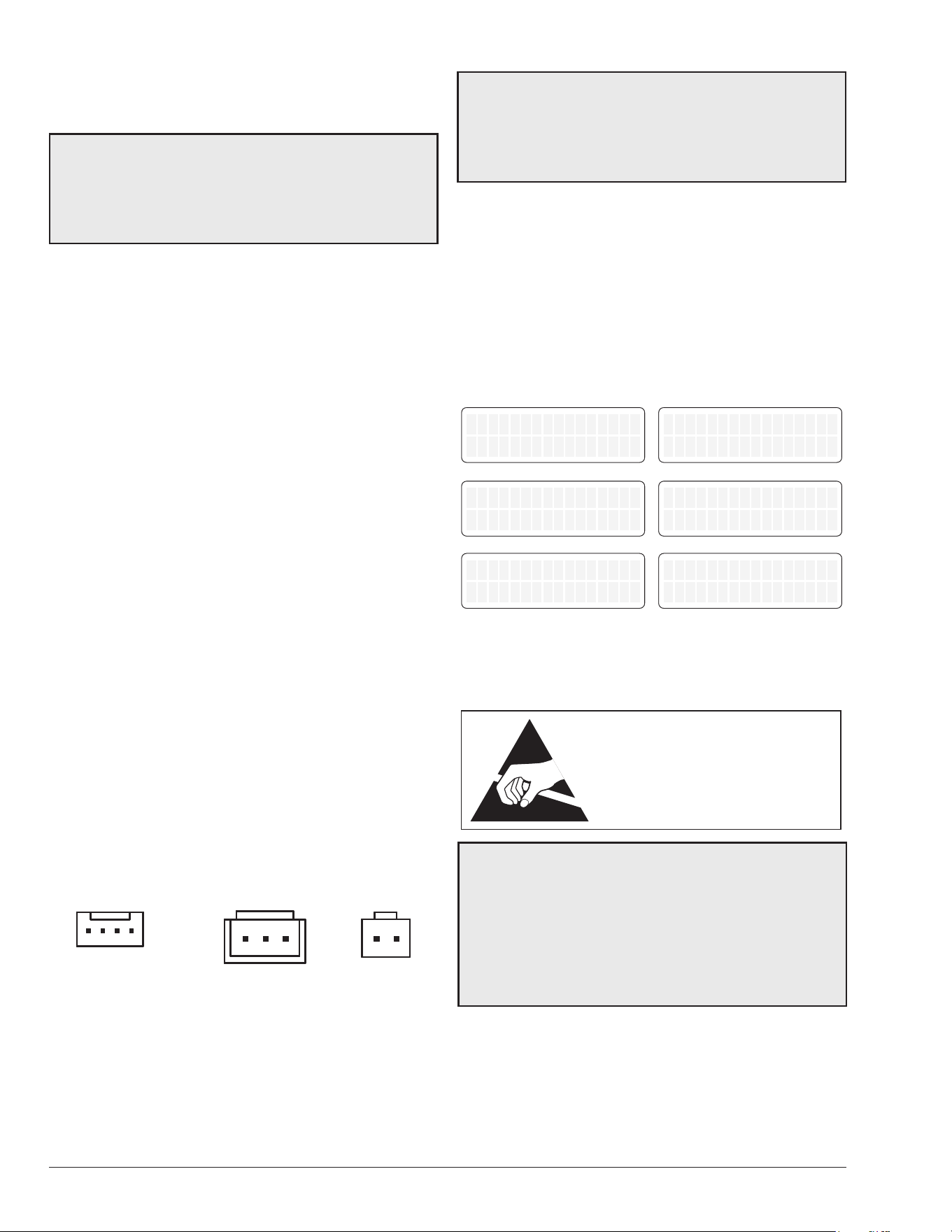
32
16. REMOTE MODE
SELECTOR
A
WARNING The ability to properly perform service
on this equipment requires a certain level of expertise,
mechanical skills, and access to the necessary tools and
equipment. If you do not possess these, do not attempt
to perform any service on this equipment other than
those procedures recommended in this manual.
The heater controller is remote-ready. The digital display
shows the actual pool temperature, operating status, and
service messages. The touch keys on the control panel
allow you to select the desired pool or spa temperature
before the remote mode is enabled. The LCD indicates
when a remote system is controlling the heater by
displaying "Remote" on the display. When connecting the
heater to a remote system, identify whether it is a two- or
three-wire remote system.
• REMOTE mode is accessed by pressing and
holding the UP and DOWN keys simultaneously for
5-seconds.
• If the UP, DOWN, or MODE keys are pressed while
in REMOTE mode, the display will read "Exit Remote
Mode to Adjust Temp". The mode and temperature
set points are not changed.
• Press and hold the UP and DOWN keys for 5-seconds
to exit REMOTE mode. When exiting REMOTE
mode, the control always selects the OFF mode.
Select the appropriate instruction listed in the following
paragraphs to properly install the remote to the heater.
Remote Wiring Connector
The heaters are equipped with the ability to work with
external remote controls and automation systems. The
supplied 3-pin remote wiring located in the packaging
installed on connector "P7" supplies power out to either
a toggle switch or the switch contacts of a third-party
automation controller. The remote works by either making
or breaking the circuit created by the remote wiring.
P16
P7
POWER
P1
P16
P7
POWER
P1
P16
P7
POWER
P1
REMOTE
Figure 57. Remote Wiring Connector
NOTE: Typically, a remote automation controller does
not supply power to the heater, it only provides a
switching function to turn the heater On or Off. If your
remote controller is supplying its own voltage to the
heater, it will not work with this heater and may damage
the digital circuit board.
Activating the Remote Mode
To activate or deactivate the remote mode, press and
hold the UP and DOWN arrow keys simultaneously for
5-seconds.
The rst line in the LCD displays "Remote" and "Off", "Pool"
or "Spa" and the temperature setpoint. The second line of
the LCD displays "Water Temp" and water temperature
alternating with heater status message. See Figure 58.
Remote OFF
Water Temp 68F
Remote OFF
Water Temp 68F
Remote OFF
No Demand
Remote OFF
No Demand
REMOTE MODE ENABLED
Remote Pool 85F
Water Temp 85F
Remote Pool 85F
Water Temp 85F
Remote SPA 90F
Water Temp 68F
Remote SPA 90F
Water Temp 68F
Remote SPA 90F
Heating
Remote SPA 90F
Hea�ng
Remote Pool 85F
No Demand
Remote Pool 85F
No Demand
Figure 58. Remote Operation Modes
Remote Control Wiring
ATTENTION
OBSERVE PRECAUTIONS
ELECTROSTATIC
SENSITIVE DEVICES
A
CAUTION: Electrostatic Discharge (ESD) damage
can be caused by direct or indirect contact with the
wiring or circuit board. When one walks to the heater
area, an electrostatic charge accumulates on the body.
Contact of a nger allows the body to discharge, possibly
causing device damage. This damage can be limited if
the service person discharges himself, following ESD
preventive/removal practices, and holds on to the heater
enclosure for 5-seconds before proceeding.
Important Installation Notes for Remote or External
Wiring Conguration:
• Remote wiring must be run in a separate conduit.
• Remote wiring must not be run parallel to high
voltage lines.
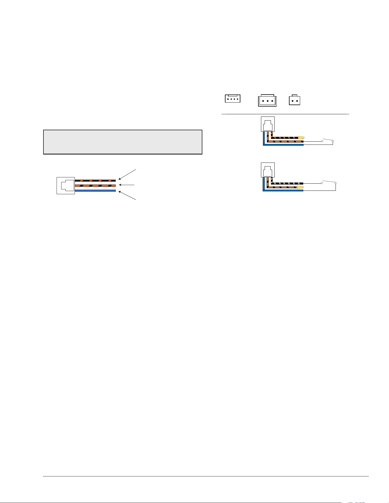
33
• For runs of under 30 feet (9 m), remote wiring should
have stranded conductors with a minimum of 22
AWG, 600V, cable twisting 1.5" to 2.5" (3.8 to 6.4 cm)
lay and jacketed.
• For runs over 30 feet (9 m), the conductors should be
a minimum of 20 AWG, 600V, cable twisting 1.5" to
2.5" (3.8 to 6.4 cm) lay that is shielded and jacketed.
• Maximum cable length recommended is 200 feet
(61 m).
• For both two- and three-wire remote systems, the
provided 3-pin REMOTE connector "P7" must be
utilized.
NOTE: The remote wires must be connected to the
3-wire remote interface harness before the connector is
plugged into the board.
SET POOL
(BLACK WITH ORANGE)
SET SPA
(ORANGE WITH BLACK)
24VAC
(BLUE)
Figure 59. 3-Wire Remote Harness
2-Wire Remote Control (On-Off)
This application assumes that only one heating function
(pool or spa) is required.
1. Turn on power to the heater.
2. For a remote controller without its own thermostat,
push the MODE key to the “POOL” or “SPA” mode and
set the desired setpoint (e.g.102°F (39°C) for spa).
3. For a remote controller with its own thermostat, push
the MODE key to select “POOL” or “SPA” mode and
set the temperature to the highest setting available on
the control. The actual setpoint will be controlled by
the remote controller.
4. Turn the MODE button to "OFF" and remove power
from the heater.
5. On the 3-wire remote harness, connect the BLUE wire
to one side of the remote automation controller and
connect the other side to either the ORANGE/BLACK
wire for “SPA” operation or the BLACK/ORANGE wire
for “POOL” operation. See Figure 60.
6. Attach wire nut on the unused wire of the harness.
7. Install the “3-wire Remote Harness” to the "P7"
connector and turn power "ON" to the heater. See
Figure 60.
8. Activate remote mode in the heater. Press and hold
the UP and DOWN arrow keys simultaneously for 3 to
5-seconds.
BLUE - 24VAC OUTPUT
REMOTE CONTROLLER
SPA ON/OFF
WIRE NUT BK/ORN
SPA MODE
SELECTOR
OR
POOL MODE
SELECTOR
REMOTE CONTROLLER
POOL ON/OFF
BLUE - 24VAC OUTPUT
WIRE NUT ORN/BK
3A 3A
P16
USER INTERFACE
P7
REMOTE
SELECTOR
POWER
24VAC
P1
MAIN
FUSE
VALVES
FUSE
F1
F2
VARIABLE
SPEED PUMP
P8
PUMP
P5
P19P20
3-WAY
VALVE2
3-WAY
VALVE1
AUX2
AUX1
3A 3A
P16
USER INTERFACE
P7
REMOTE
SELECTOR
POWER
24VAC
P1
MAIN
FUSE
VALVES
FUSE
F1
F2
VARIABLE
SPEED PUMP
P8
PUMP
P5
P19P20
3-WAY
VALVE2
3-WAY
VALVE1
AUX2
AUX1
3A 3A
P16
USER INTERFACE
P7
REMOTE
SELECTOR
POWER
24VAC
P1
MAIN
FUSE
VALVES
FUSE
F1
F2
VARIABLE
SPEED PUMP
P8
PUMP
P5
P19P20
3-WAY
VALVE2
3-WAY
VALVE1
AUX2
AUX1
REMOTE
Figure 60. 2-Wire Remote Harness Installation
3-Wire Remote Control Using Three-
Position Selector (Pool-Off-Spa, or Low-Off-
High)
This application assumes that both heating functions (pool
and spa) are required.
1. Turn on power to the heater.
2. For remote controllers without its own thermostat,
push the MODE key to the “POOL” or “SPA” mode
and set the desired temperature for each, e.g. 80°F
(27°C) for Pool and 102°F (39°C) for spa.
3. For remote controller with its own thermostat , push
the MODE key to select “POOL” or “SPA” mode and
set both temperature setpoints to the highest setting
available on the heater. The actual setpoint will be
controlled by the remote controller.
4. Turn the MODE key to "OFF" and remove power from
the heater.
5. On the 3-wire remote interface harness, connect
the BLUE wire to one side of the remote automation
controller and connect the ORANGE/BLACK wire for
“SPA” operation and the BLACK/ORANGE wire for
the “POOL” operation. See Figure 61.
6. Install the 3-wire remote interface harness to the
"P7" connector and turn power ON to the heater. See
Figure 61.
7. Activate remote mode in the heater. Press and hold
the UP and DOWN arrow keys simultaneously for
5-seconds.
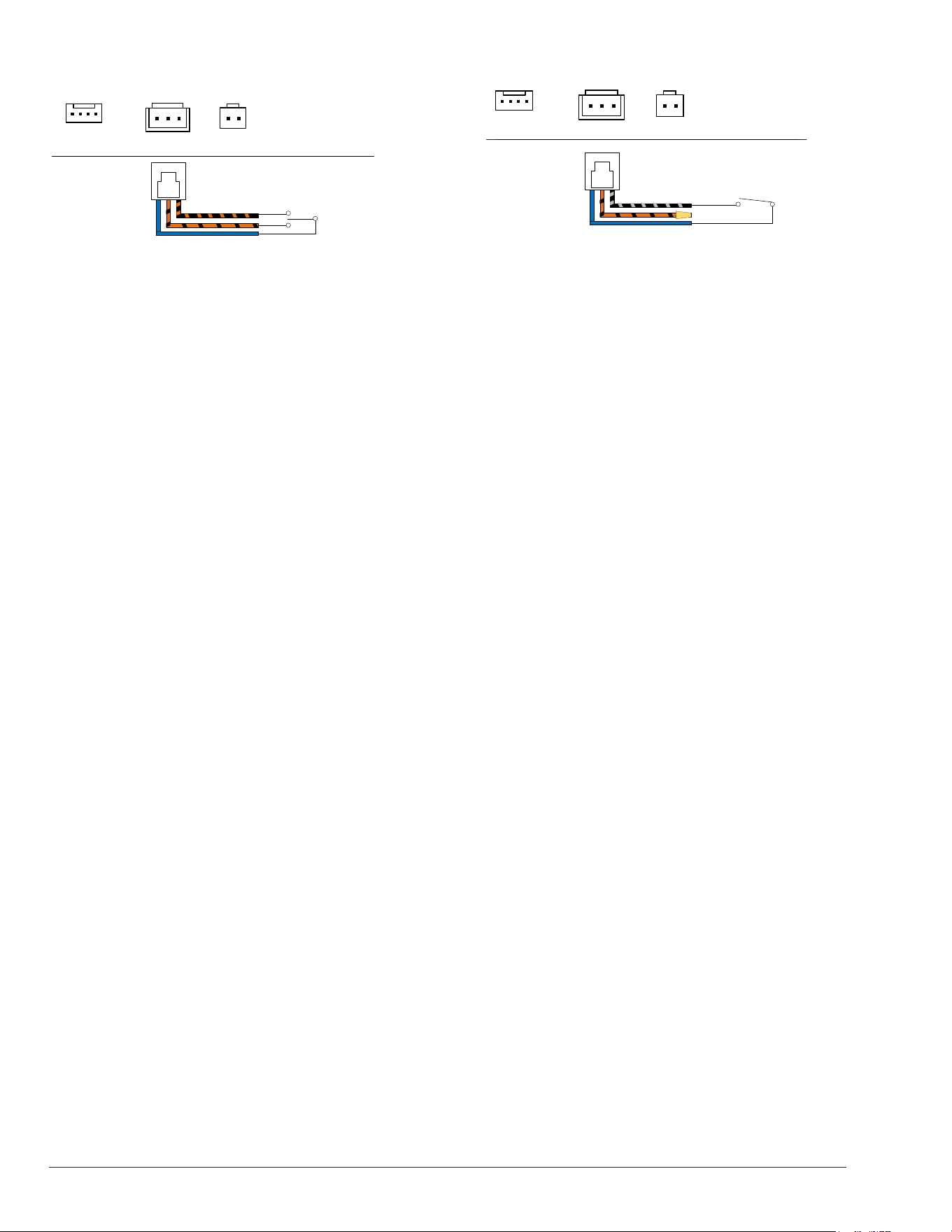
34
BLUE - 24VAC OUTPUT
REMOTE CONTROLLER
POOL AND SPA
OPERATION
POOL AND SPA
COMMANDS
3A 3A
P16
USER INTERFACE
P7
REMOTE
SELECTOR
POWER
24VAC
P1
MAIN
FUSE
VALVES
F1
F2
3A 3A
P16
USER INTERFACE
P7
REMOTE
SELECTOR
POWER
24VAC
P1
MAIN
FUSE
VALVES
F1
F2
3A 3A
P16
USER INTERFACE
P7
REMOTE
SELECTOR
POWER
24VAC
P1
MAIN
FUSE
VALVES
F1
F2
REMOTE
Figure 61. 3-Wire Remote Harness Installation
Remote Control Options for Heat/Cool
Models
In Heat/Cool models, the 3-wire remote "Pool" terminal
can be congured to operate as "Pool Heat", "Pool Cool"
or "Pool Auto". The default mode for remote pool is "Pool
Heat".
1. To change this setting enter "Program Menu" by
pressing and holding SERVICE + MODE keys
simultaneously for 10-seconds.
2. Press SERVICE key until "Remote Pool Mode" is
displayed.
3. Use the UP or DOWN keys to select "Pool Cool",
"Pool Auto" or "Pool Heat".
4. After selection is completed, press MODE key to exit
the "Program Menu".
5. For remote controllers without its own thermostat,
use the MODE key to select the pool mode (pool
heat, pool cool or pool auto). Then use the UP/
DOWN keys to adjust the temperature setpoint to be
used in remote mode.
6. For remote controller with its own thermostat, push
the MODE key to select the pool mode (pool heat,
pool cool or pool auto) and set the temperature
setpoints to the highest/lowest setting available on
the heater. The actual setpoint will be controlled by
the remote controller.
7. Turn "OFF" with MODE key and remove power from
the heater.
8. For a 2-Wire remote control, connect the BLUE wire
to one side of the remote controller and connect the
other side to the BLACK/ORANGE wire for "POOL"
operation.
9. Attach wire nut on the ORANGE/BLACK wire of the
3-wire remote harness. See Figure 62.
POOL MODE
SELECTOR
REMOTE CONTROLLER
POOL ON/OFF
BLUE - 24VAC OUTPUT
WIRE NUT ORN/BK
3A 3A
P16
USER INTERFACE
P7
REMOTE
SELECTOR
POWER
24VAC
P1
MAIN
FUSE
VALVES
F1
F2
3A 3A
P16
USER INTERFACE
P7
REMOTE
SELECTOR
POWER
24VAC
P1
MAIN
FUSE
VALVES
F1
F2
3A 3A
P16
USER INTERFACE
P7
REMOTE
SELECTOR
POWER
24VAC
P1
MAIN
FUSE
VALVES
F1
F2
REMOTE
Figure 62. 2-Wire Remote Harness Installation
10. For 3-wire control, connect the BLUE wire to one side
of the remote controller and connect the ORANGE/
BLACK wire for "SPA" operation and the BLACK/
ORANGE wire for the "POOL" operation. See Figure
61.
11. Install the 3-wire remote harness to the "P7" connector
and turn power ON to the heater.
12. Activate remote mode in the heater. Press and hold
the UP and DOWN arrow keys simultaneously for
5-seconds.
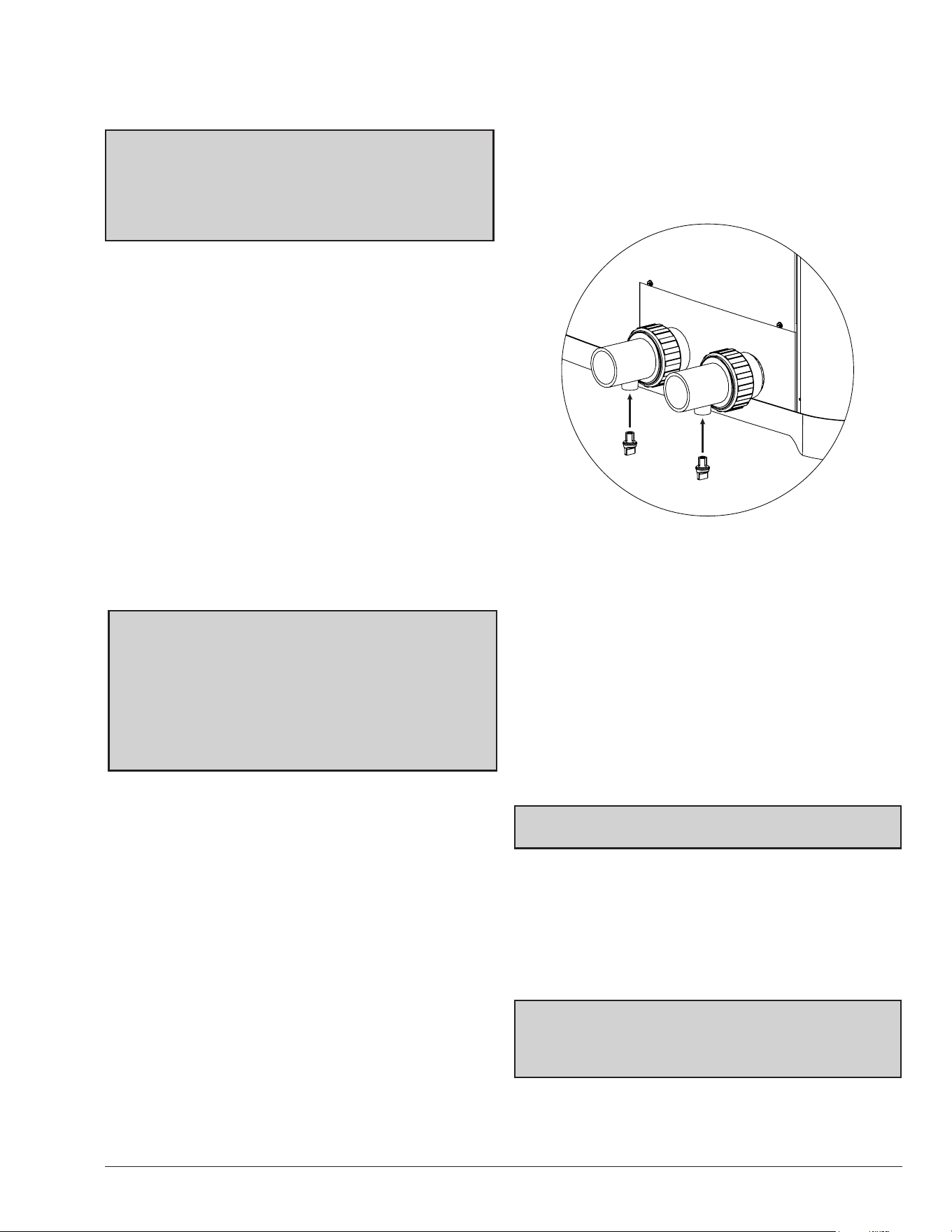
35
17. SEASONAL START-UP OR
ANNUAL CHECK
NOTE: At the beginning of the heating season or
whenever the pool water temperature is to be raised
several degrees, the pool pump and heat pump pool
heater may need to operate continuously for several
days. During summer months, only a few hours per day
may be necessary or none at all.
1. Remove leaves, pine needles, etc., from the
evaporator coil. Clean the coil by gently applying a
mild solution of household liquid soap and water.
2. Remove the side louvered panel by removing the
single screw at the top and the two (2) screws on the
middle part of the panel. Lift and pull the bottom out.
The panel will easily come away from the cabinet
giving access to the coil for cleaning.
3. Gently rinse the coil with water; DO NOT use high
pressure.
4. Re-install the side panels and secure each with the
screws removed in Step 2.
5. Backwash or otherwise clean the pool filter. If
necessary, clean the skimmer basket and pump
strainer.
6. Set the valves to ensure proper water flow through
the unit.
NOTE: If the pool pump and heat pump pool heater shut
OFF before the water temperature is raised to the desired
level, you must lengthen the running time of both. To do
this, reset the time clock dial for the longer running time,
or manually operate the pump with the timer override
switch. Since the heater capacity and efciency are both
greater at higher ambient air temperatures, run time
should be set to take advantage of all daylight hours,
when the air is generally warmer.
18. SUMMER SHUTDOWN
If you do not plan to use the heater during the summer
months, secure and protect it as follows:
1. Turn the unit circuit breaker or disconnect switch to
OFF.
2. Leave the valves set the way they are unless
additional circulation is required. DO NOT stop all
flow through the heater.
3. IMPORTANT: Remember to reset the valves before
the next heating season, or the unit will not operate
properly.
19. FREEZE PROTECTION
If the unit is installed in a location subject to freezing
conditions, it is important to protect the water circuit from
freezing, just as should be done for the pump and lter.
System Drain-Down
1. Turn the unit circuit breaker or disconnect switch to
OFF.
2. With the pool pump OFF, close the external shut- off
valves and remove the drain plugs located in the
inlet and outlet water unions to allow water to drain.
See Figure 63.
INLET
OUTLET
DRAIN PLUGS
Figure 63. Drain Plug Locations
3. Use a wet/dry vacuum or air pressure to remove
excess water, as necessary.
4. Once the water is drained, reinstall the drain plugs.
5. Cover the unit with a waterproof cover.
Continuous Pump Operation
It is also possible in some areas to prevent unit freeze
damage by operating the pump continuously during
freezing weather. However, this results in signicantly
higher pump operating costs. Further, if a sustained power
failure occurs, the unit MUST be drained anyway, or freeze
damage could result.
NOTE: The heater manufacturer is not responsible for
maintenance adjustments.
20. MAINTENANCE
The following maintenance procedures are designed
to keep your unit operating at a high-level of reliability.
Maintenance must be performed on a periodic basis to
maintain warranty coverage and prevent system failures
and performance degradation.
CAUTION: To clean the ns, remove the side louvered
panels and spray gently with a garden hose. DO NOT
pressure wash. Doing so will bend the ns and can void
the warranty.
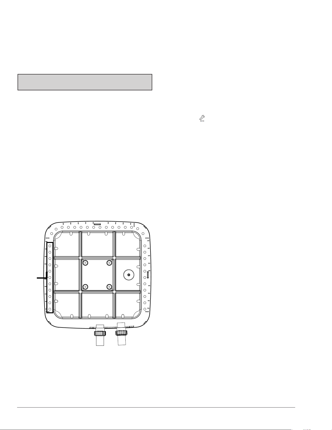
36
Air Coil Cleaning
Efcient operation depends on free circulation of air
through the thin and tightly-spaced ns of the evaporator
coil(s). The evaporator must be cleaned whenever it has a
buildup of dirt or debris.
Cabinet Care (optional)
A
WARNING: Shut OFF electricity to the unit before
cleaning.
The powder-coated cabinet is designed for outdoor use
and requires little care. However, you can clean it if you
wish. Wash the cabinet with soap and water.
Unplug Condensation Drain Holes
The unit extracts humidity from the air as it passes through
the coil, similar to the way a cold drink outside “sweats”
on a hot day. This condensation drains from the bottom
of the unit.
1. Routinely check to be sure the condensation drain
holes in the base of the unit are not plugged with dirt
or debris. See Figure 64 for condensate drain hole
locations.
2. If condensation becomes a problem, optional drain
pans may be available from your heat pump pool
heater distributor or pool dealer.
DRAIN
HOLES
UNIT’S BOTTOM VIEW
Figure 64. Condensate Drain Hole Locations
21. TROUBLESHOOTING
Before troubleshooting the system, ensure that:
• All mechanical and electrical connections are secure
and tight
• All system wiring is correct
• Fuse is not blown (3A Automotive “ATO” type fuse
for 24VAC)
• That a system ground is properly connected to the
heater. Nuisance shutdowns are often caused by a
poor or erratic ground.
The service display can be accessed by pressing
SERVICE key .
The service display does not affect operation of the unit
which continues to operate in the background. When in
this menu, the UP or DOWN buttons will toggle through
the various information reported. For more details about
Service menu, refer to section 11 "Service Menu", on
page 14.
If your unit does not operate, or simply does not heat
your pool water, fault messages on the front control
panel can provide valuable clues as to what is wrong,
and may even indicate precisely what the problem is.
Always observe these messages before calling a service
representative. By reporting on the telephone the fault
messages that are showing, the service representative
may be able to solve the problem without the expense
of a service call.
A. Unit Is Running, But Not Heating
• Is water flow through the unit adequate? Check
the unit for obstructions, such as a clogged filter
pump strainer, a dirty filter, or valves not positioned
correctly.
• Is the ejected air from the unit 8°–10°F (4.4°C–5.5°C)
cooler than incoming air? If so, the unit is extracting
heat from the air and transferring it to the pool.
• Is water condensing on the evaporator and internal
copper pipes? This is also evidence of heat removal
from the air. When the air is cool with low humidity,
condensation may not be evident.
• How long has the unit been operating? During initial
pool heating in cold weather, it may require a week to
elevate the water temperature to a comfortable level.
Normally, it takes about 4-days.
• How many hours per day is the unit operating?
Remember that the heater only operates while
the pool pump is running. Set the time clock to
permit 24-hour per day operation. After the desired
temperature is reached, return the unit to normal
operation of 8–10 hours per day.

37
• Is airflow through the unit being obstructed?
Restrictions such as shrubbery, tall grass, dirty
coils, or any other obstruction to airflow will reduce
performance.
• Is the pool blanket/cover being used? Uncovered
pools can lose up to 10°F (5.5°C) per night compared
to 4°F (2.2°C) or fewer when a blanket is used.
Without a blanket, the total heat gained during the
day can be lost overnight.
• Are rapid heat losses occurring in some other way,
such as high-wind, spillage, rainfall, flow through
solar panels at night, or a high water table?
NOTE: If the heat pump pool heater shuts off before
the water temperature is raised to the desired level,
you must increase the running time. To do this, reset
the time clock dial for a longer running time or manually
operate the pump with the timer override switch. Since
the unit capacity and efciency are greater at higher
ambient air temperatures, the run time should be set
to take advantage of all daylight hours when the air is
generally warmer.
B. Unit Is Not Running
• Is the temperature display ON? If not, the circuit
breaker may be shut OFF or tripped. Reset the
breaker by switching it OFF, and then back ON.
Verify that the breaker is set and operating properly
before calling for service.
• Are the Pool/Spa settings correct? Verify that
the temperature has been properly set on the
thermostat, and that it is higher than the current
water temperature.
• Have you waited approximately 3-minutes for the
time delay? After the unit has been running and
then shut OFF for any reason, there is a delay
before operation can begin again. The display will
read “Comp Start Delay” when this 3-minute delay
is active.
NOTE: The heater will not run when the Remote
position is selected on the pool/spa control and there is
no remote control system attached.
C. Condensation Seems Excessive
Heat pump pool heaters can produce a large amount of
condensation (water) during operation. If you suspect that
the unit is leaking:
• Shut the unit OFF and leave the filter pump running
to see if the water stops dripping. If the water stops
dripping, the unit is not leaking.
NOTE: Use a pool chemistry test kit to conrm there is
no chlorine in the water.
22. SERVICE CALL
VERIFICATION
NOTE: The Service number is located on the front of the
heater at the brand label.
Before you make a service call, rst determine if the
problem is:
• Warranty Service - must have model number,
serial number and date of installation or Warranty
Registration conrmation number.
• Unit operation (power supply, water ow, or time
clock adjustment).
NOTE: The manufacturer is not responsible for these
adjustments.
Power Supply
• Verify that all circuit breakers are reset and working
properly.
• If the temperature display on the control panel still
does not light, contact the installing dealer, since it
may be a power problem requiring an electrician.
Water Flow
• Verify that the pool lter is clean to provide good ow.
• Verify that valves are properly positioned to allow
adequate water ow through the unit.
Time Clock Adjustment
Verify that the time clock is set to permit the unit to run
long enough to heat properly.
Set Factory Defaults
If programming is disarranged and no operation can
reliably be made, the control board can be reset to Factory
Default values. This operation changes all adjustable
settings to factory default settings.
NOTE: Previous settings will be erased and are no
longer recoverable. All settings will have to be re-entered
by hand to re-establish proper operation.
After setting the factory defaults, check the Program,
Installer, and Schedule menus as necessary to congure
the desired operation settings and optional controls.
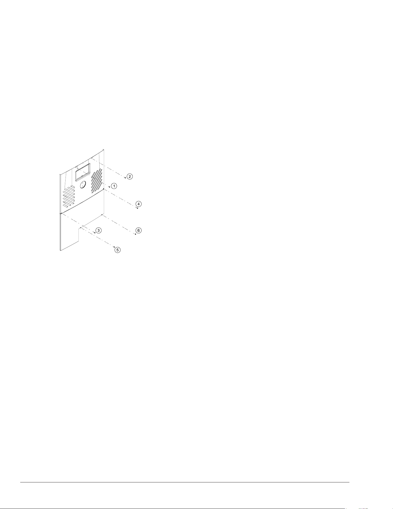
38
Service Access to Heaters
If service access to the heater is required, it is
accomplished by removing the control cover panel and
service access panel (Figure 65) to provide a wide access
to get to (1) compressor, (2) heat exchanger, (3) thermal
expansion valve (TXV), (4) reversing valve/solenoid valve
(if equipped), (5) ow switch (if equipped), and (6) sensors
(water, ambient and coil). To gain access, follow the steps
below:
1. Shut off all power to the unit to avoid any possibility
of electrical shock or damage to components.
2. Remove the heater’s front control cover panel by
unscrewing the six (6) screws using a 1/4" hex head
screwdriver. See Figure 65.
Figure 65. Sheet Metal Screws to Remove Control Panel
3. Pull the front panel's bottom down and outward.
IMPORTANT: Disconnect the wire attached to the
rear of the user interface. The panel is now free for
removal.
4. Set the control panel cover aside to reinstall when
service is completed.
5. Install service access panel and slide control cover
panel up to its place and secure with screws removed
in Step 2.
6. Turn ON power and start operation as needed.
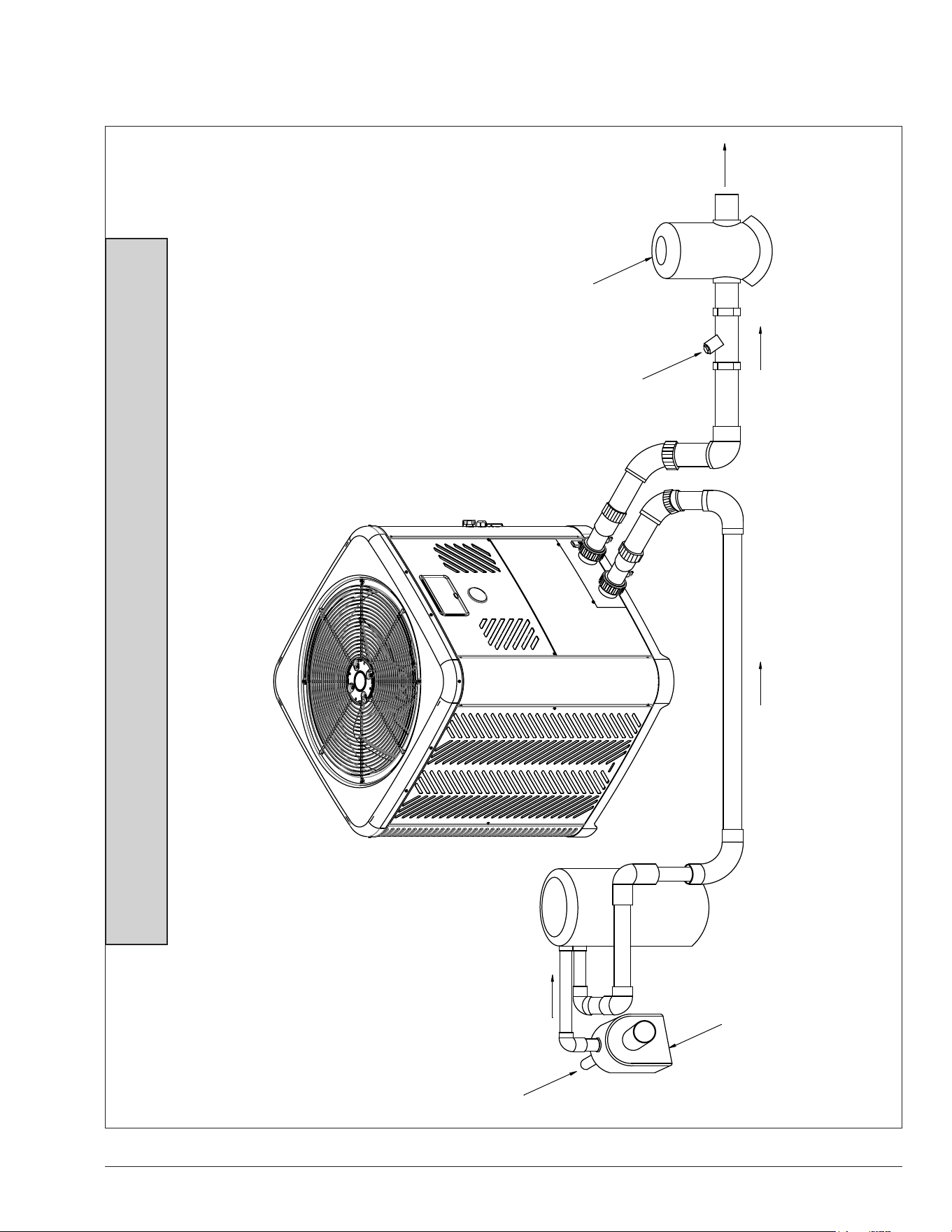
39
23. PLUMBING DIAGRAMS
WATER OUT
(TO POOL
OR SPA)
FILTER
WATER IN
(TO POOL
OR SPA)
PUMP
CHECK
VALVE
CHEMICAL
INTRODUCTION
Figure 66. Plumbing Schematic – No External Bypass (Plumb the heater AFTER the lter and before any chlorinators.)
NOTE: Models 4550 – For systems with pumps less than 1-1/2 HP (under 40 GPM / 151 LPM)
Models 5550-8550 – For systems with pumps less than 2 HP (under 50 GPM / 189 LPM)
No external bypass required.
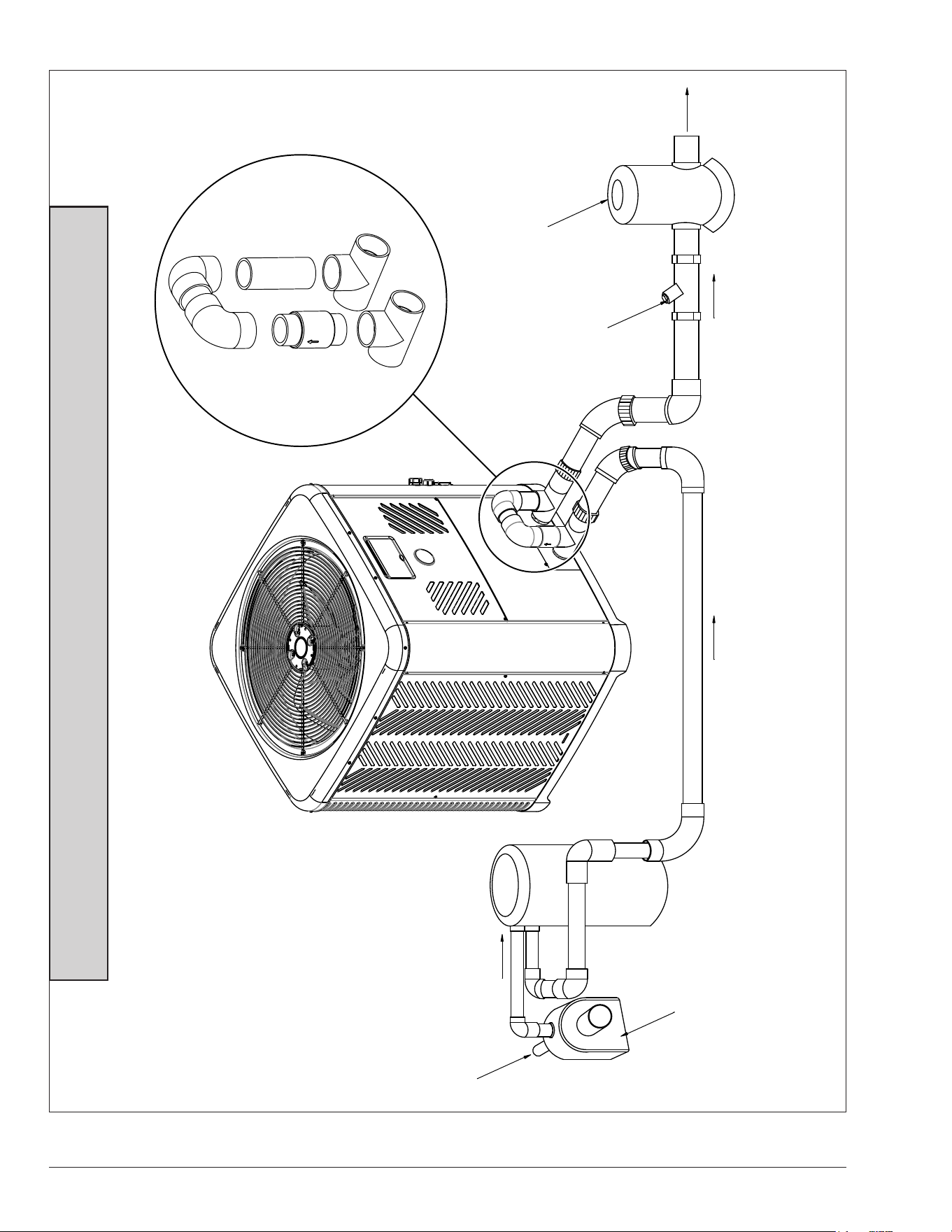
40
WATER OUT
(TO POOL
OR SPA)
FILTER
WATER IN
(TO POOL
OR SPA)
PUMP
CHECK VALVE
CHEMICAL INTRODUCTION
EXTERNAL BYPASS
Figure 67. Plumbing Schematic – External Bypass (Plumb the heater AFTER the lter and before any chlorinators.)
NOTE: Models 4550 – For systems with pumps of 1-1/2 HP or greater (over 40 GPM / 151 LPM)
Models 5550-8550 – For systems with pumps of 2 HP or greater (over 50 GPM / 189 LPM)
External bypass required.
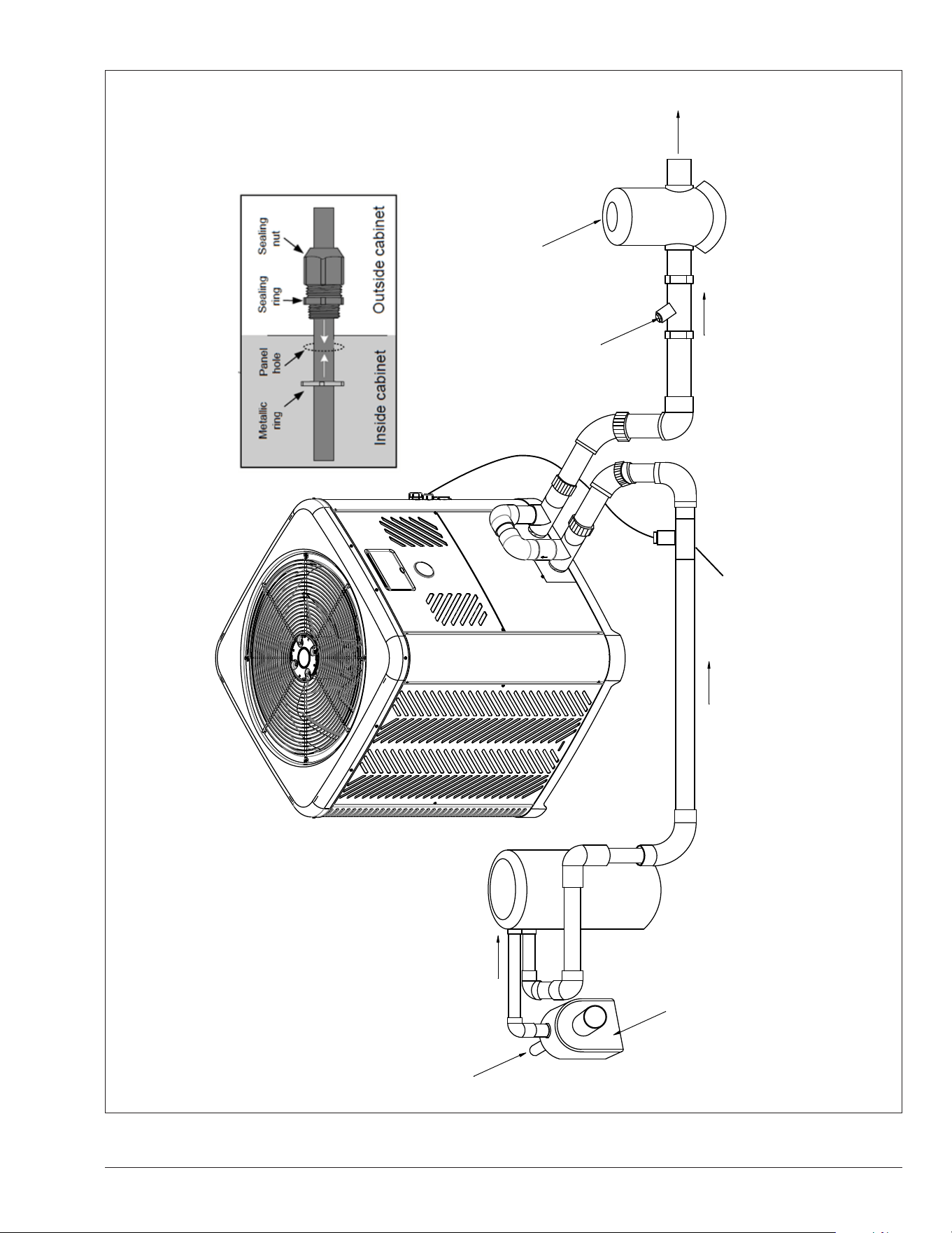
41
WATER OUT
(TO POOL
OR SPA)
FILTER
WATER IN
(TO POOL
OR SPA)
PUMP
CHECK
VALVE
CHEMICAL
INTRODUCTION
INLET
OUTLET
WATER FLOW SWITCH
[Kit# H000166]
WATER FLOW SWITCH
WIRING
NOTE: THE WFS MUST BE INSTALLED
IN CLOSE PROXIMITY TO THE
HEATER, RAYPAK RECOMMENDS TO
INSTALL NO FURTHER THAN 2 FT.
Figure 68. Plumbing Schematic – Above Ground Pool Water Flow Switch Installation
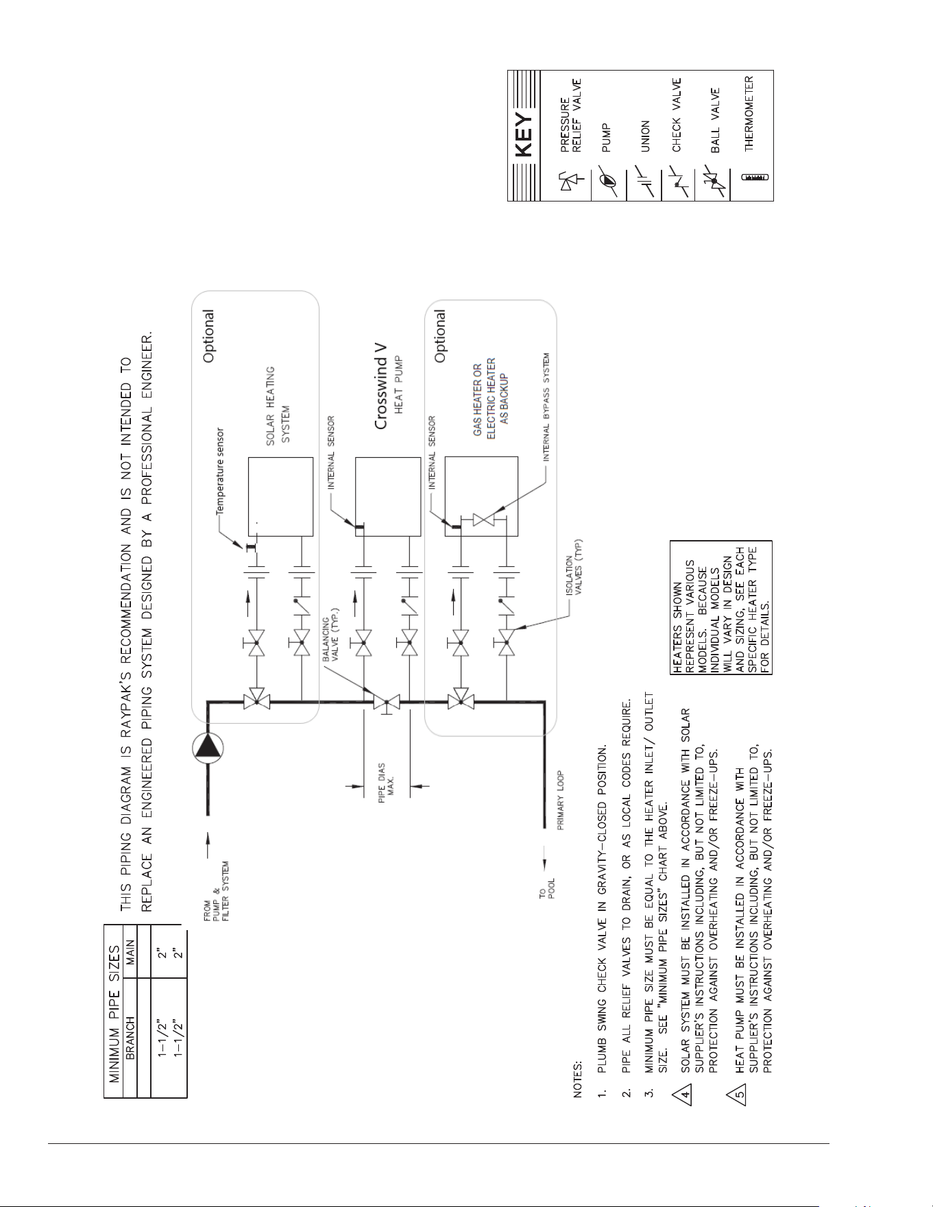
42
Figure 69. Piping for Heat Pump Pool Heater
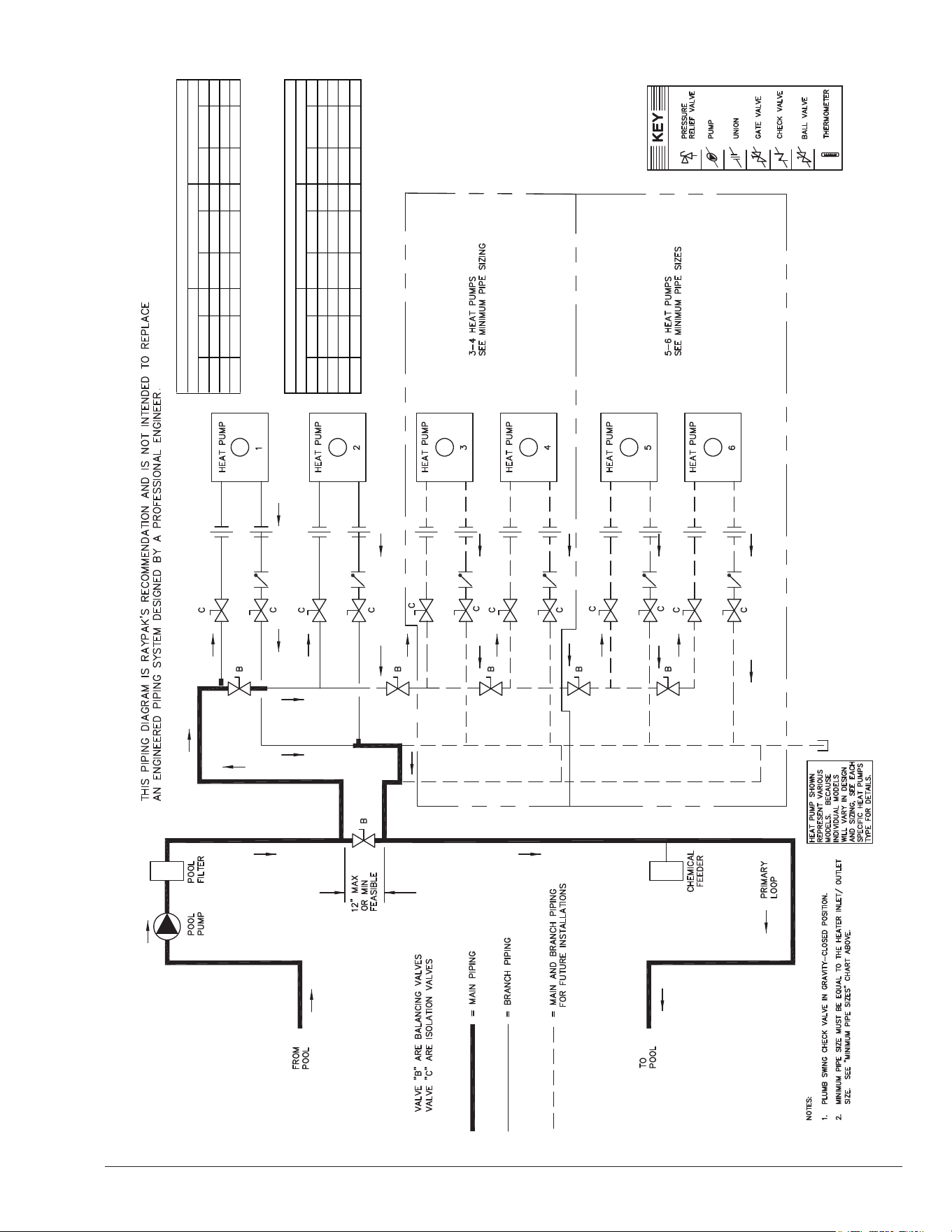
43
Figure 70. Piping for Multiple Heaters, Primary/Secondary
EXTEND 12” PAST
HEATER INLET FOR
HYDRAULIC BALANCING.
4550
BRANCH MAIN BRANCH MAIN BRANCH MAIN
20 GPM 1-1/2" 1-1/2" 20 GPM 1-1/2" 1-1/2" 20 GPM 1-1/2" 2"
30 1-1/2" 1-1/2" 30 1-1/2" 2-1/2" 30 1-1/2" 3"
40 1-1/2" 2" 40 1-1/2" 3
*Sizing based on10 ft/sec flow rates
MINIMUM PIPE SIZES
2 UNITS 3-4 UNITS 5-6 UNITS
5550-8550
BRANCH MAIN BRANCH MAIN BRANCH MAIN
30 GPM
40
60
80
2"
2"
2"
2"
2"
3"
3"
4"
30 GPM
40
60
80
2"
2"
2"
2"
2-1/2"
3"
4"
4"
30 GPM
40
60
80
2"
2"
2"
2"
4"
4"
5"
5"
MINIMUM PIPE SIZES
2 UNITS 3-4 UNITS 5-6 UNITS
40 1-1/2" 4"
44
100KOhm sensors are used for water temperature
measurement. These sensors are dual thermistors
in a single sensor housing. The control uses both
sensor readings in operating the unit. If the control
measures temperatures on these thermistors which are
approximately 3°F (1.6°C) apart, the control will shut off
the compressor and show “In Sensor Fault”.
The message will be cleared and operation resume when
thermistors are within 2°F (1.1°C) of each other. The sensor
has a measurement error of less than +/- 0.5°F (0.3°C)
between 36°F and 110°F (2.2°C and 43°C) temperatures.
The control displays 100K sensor temperatures to 0.1°F
or 0.1°C resolution. The water temperature used for
thermostat decisions is the average of the 2 thermistors.
Table F. Temperature-Resistance Sensor Values
Temperature ºF (ºC) Resistance (Ω)
32 (0) 32550
41 (5) 25340
50 (10) 19870
59 (15) 15700
68 (20) 12490
77 (25) 10000
86 (30) 8059
95 (35) 6535
104 (40) 5330
113 (45) 4372
122 (50) 3605
Temperature ºF (ºC) Resistance (Ω)
32 (0) 325500
41 (5) 253950
50 (10) 199040
59 (15) 157150
68 (20) 129440
77 (25) 100000
86 (30) 80570
95 (35) 65310
104 (40) 53260
113 (45) 43680
122 (50) 36020
Water Outlet, Ambient, Coil and solar sensors
10K Sensor Resistance Values
Inlet Water Sensor
100K Sensor Resistance Values
24. RESISTANCE SENSOR VALUES
10KOhm sensors are used for the Outlet water
temperature, Ambient Air Temperature sensor, the Coil
Temperature sensor. Additionally, the control board Solar
sensor terminal is designed for a 10KOhm Temperature
sensor (eld-supplied when necessary). The sensor
has a measurement error of less than +/- 0.5°F (0.3°C)
between 36°F and 110°F (2.2°C and 43°C) temperatures.
The control displays 10K sensor temperatures to 0.1°F or
0.1°C resolution.
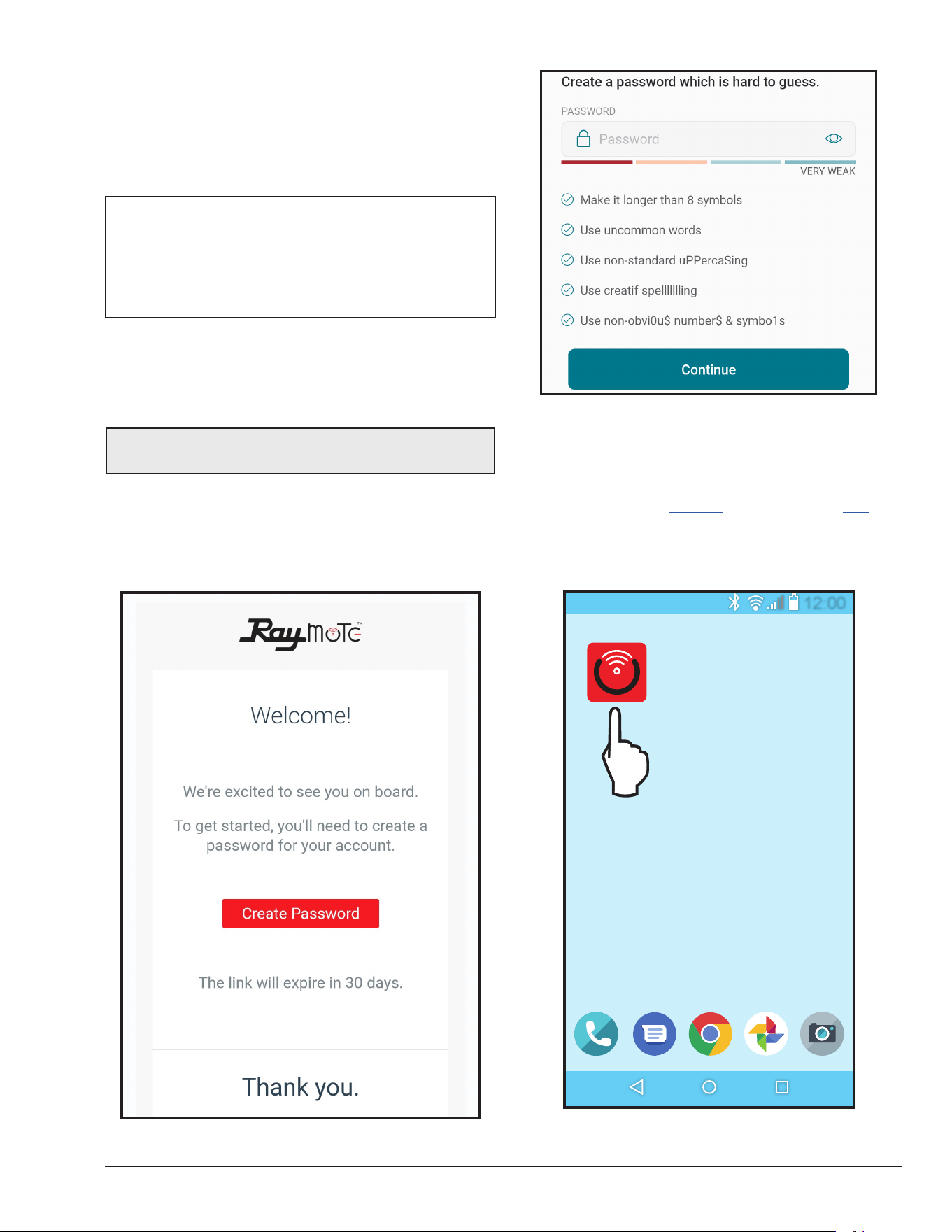
45
25. CONNECT TO WI-FI WITH
RAYMOTE
Before initiating the provisioning process, make sure
a reliable Wi-Fi access point is located near the unit or
control room and a Wi-Fi network password is available.
Date: _______________________________________
Wi-Fi Network Name
(SSID): ______________________________________
Wi-Fi Password: _______________________________
Raymote User Registration
Download Raymote app and sign up from your mobile
device. Use your email to create a new account. You'll
receive an email conrmation. See Figure 71.
NOTE: Check your email spam if you do not receive an
email within 5-minutes in your inbox.
Use your email address as the Raymote user, then create
a secure password. See Figure 72.
Once the user registration is complete, you can begin to
add your Crosswind V heaters via the Raymote mobile
app.
Figure 71. Welcome Raypak Dashboard
Figure 72. Create Password
Downloading the Raymote Mobile App
1. Download and install the Raymote mobile app from
the Google Play (Android), or App Store (iOS), on
your mobile device.
2. Find the Raymote mobile app icon on your device.
See Figure 73.
12:00
Figure 73. Find your Raymote Mobile App Icon
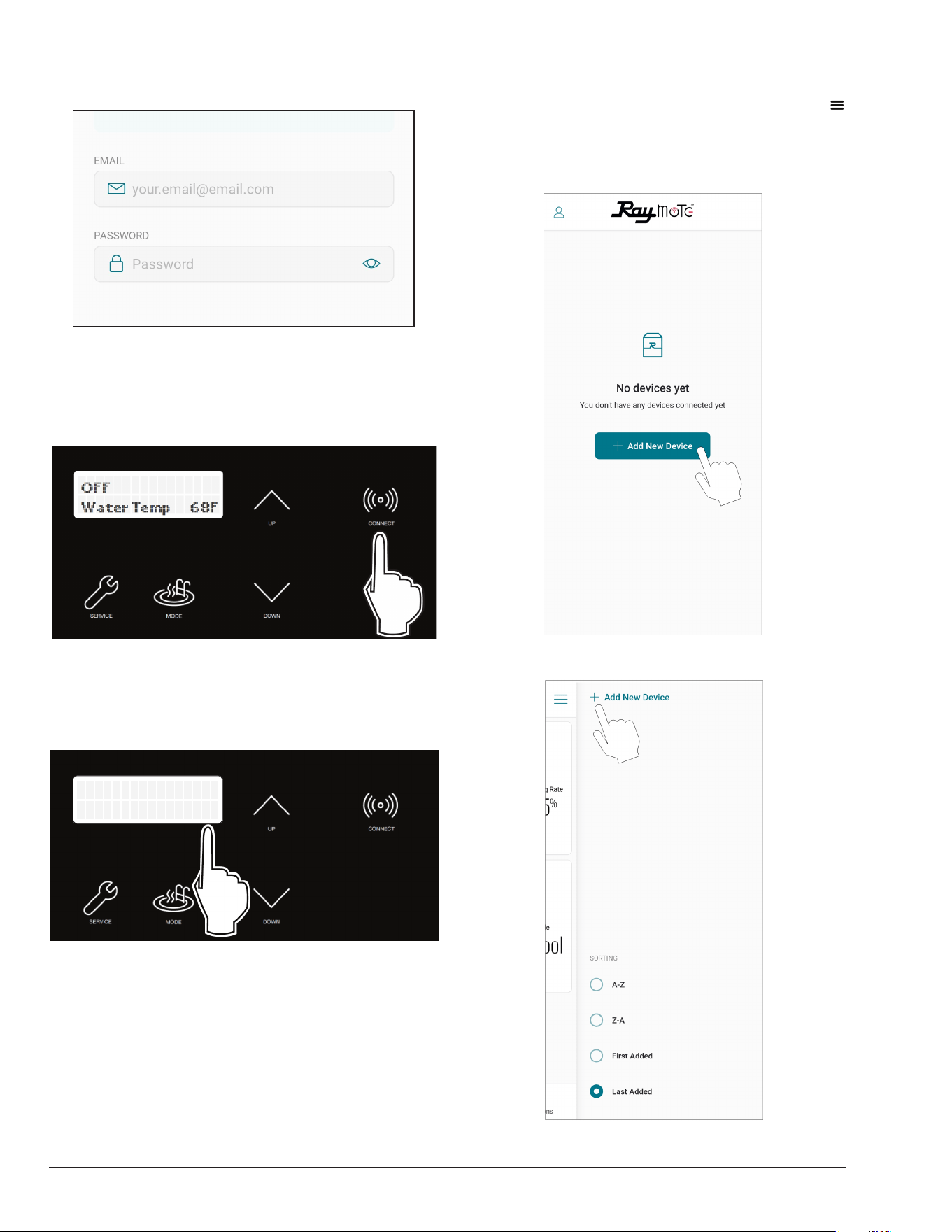
46
3. Open the Raymote mobile app and log in with your
user name and password. See Figure 74.
Figure 74. Log in the Raymote Mobile App
Preparing the Unit for Connection
1. Stand near the display of the Crosswind V unit. Press
the CONNECT key. See Figure 75.
Figure 75. CONNECT Key
2. The CONNECT menu displays the Wi-Fi State,
indicating "Ready to Config" wireless connection,
and also the HOTSPOT identifier. See Figure 76.
Outside Lockout
45 F
HPPH-XXXXX
Ready to Config
Figure 76. Wi-Fi Ready to Congure and HOTSPOT
Identier
3. At this point your unit is ready for connection.
NOTE: The following sections provide the instructions for
Android and iPhone devices.
Add a New Heater to Raymote
1. In the Raymote app, press the menu button
located at the top left corner of the screen, then press
"+ Add new device". See Figure 77.
Figure 77. Add New Device
ADD THE FIRST UNIT
OR ADD MORE NEW UNITS
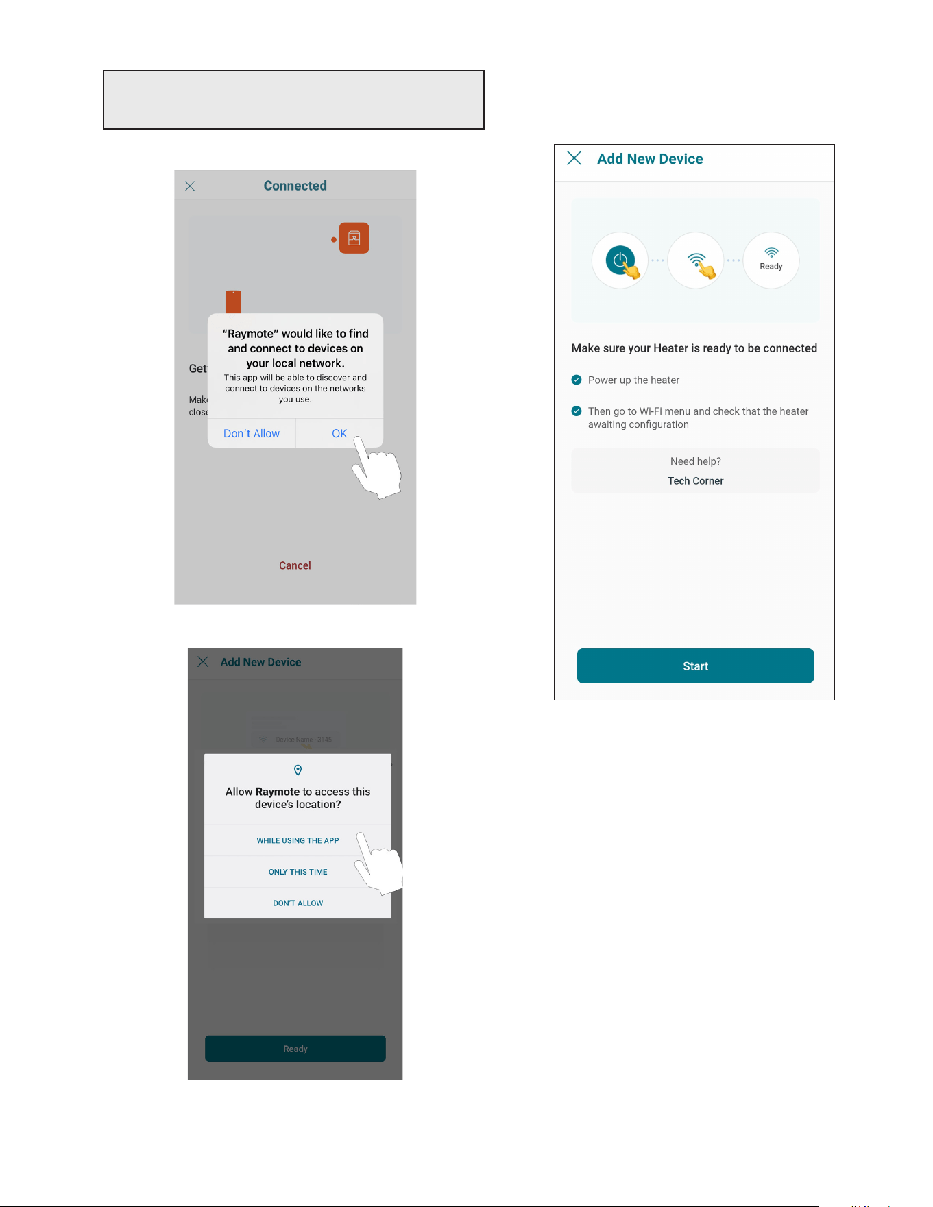
47
NOTE: The rst time you use a new phone, the Raymote
mobile app may require you grant permission to access
data. See Figure 78.
iOS
ANDROID
Figure 78. Grant Permission
2. "Check your Device" screen will appear. Ensure to
have Crosswind V heater powered and Wi-Fi signal
available in the area, then press "Start" button. See
Figure 79.
Figure 79. Check your Device
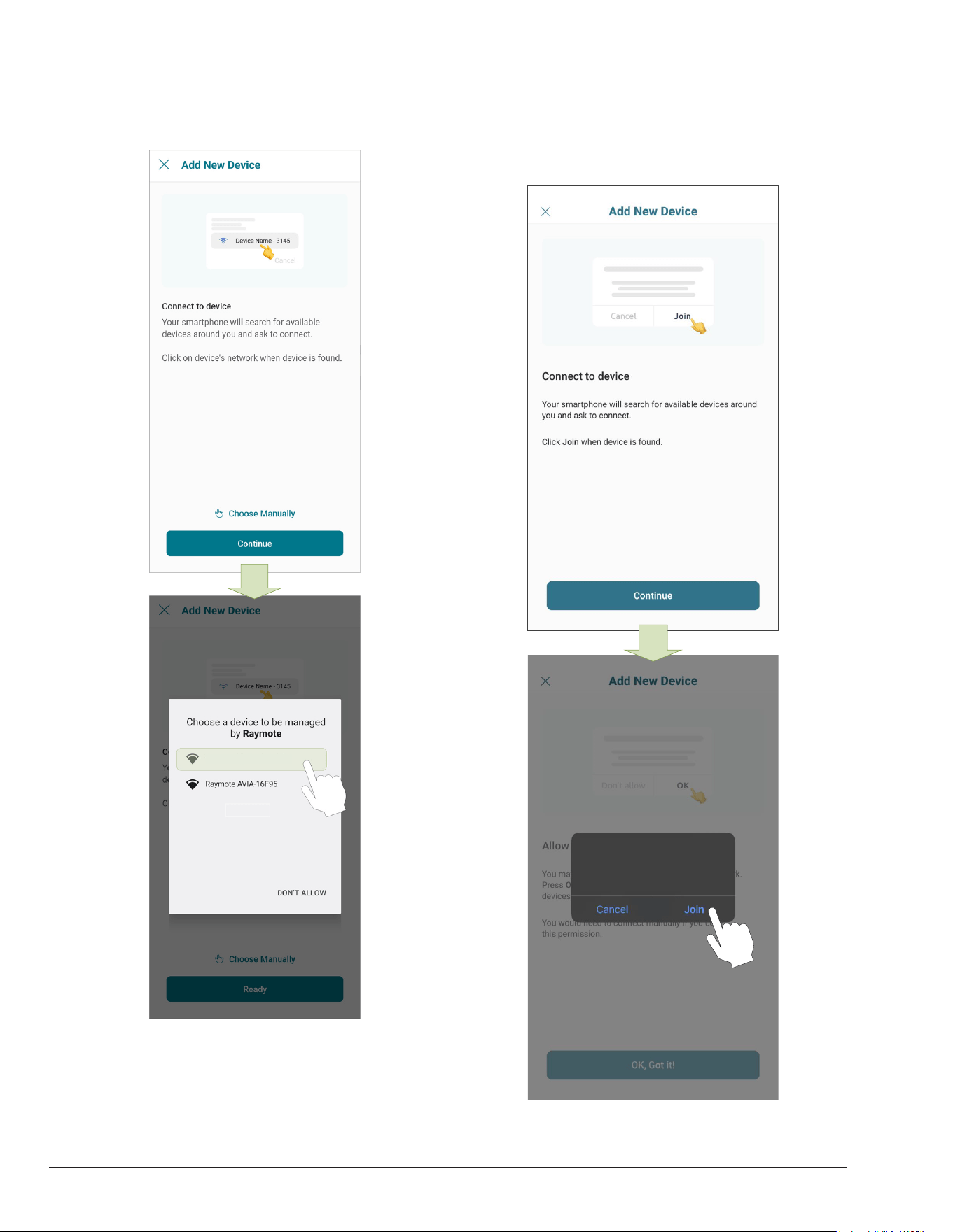
48
3. In Android: Depending on your configuration, one
or more devices will appear on the app. Select the
HOTSPOT identifier that matches the unit's display
as shown in Figure 80.
Raymote Crosswind V
Figure 80. Connect with Android Smart Phone
4. In iPhone: Raymote app will start to scan nearby
heaters. If you have multiple units ready to connect,
stand closer to the unit you want to connect first.
Press "Join" to select the displayed heater that
matches the HOTSPOT identifier, or press "Cancel"
to start the process again. See Figure 81.
“Raymote” Wants to Join
Wi-Fi Network “Raymote
HPPH-XXXXX”?
Figure 81. Connecting with iPhone
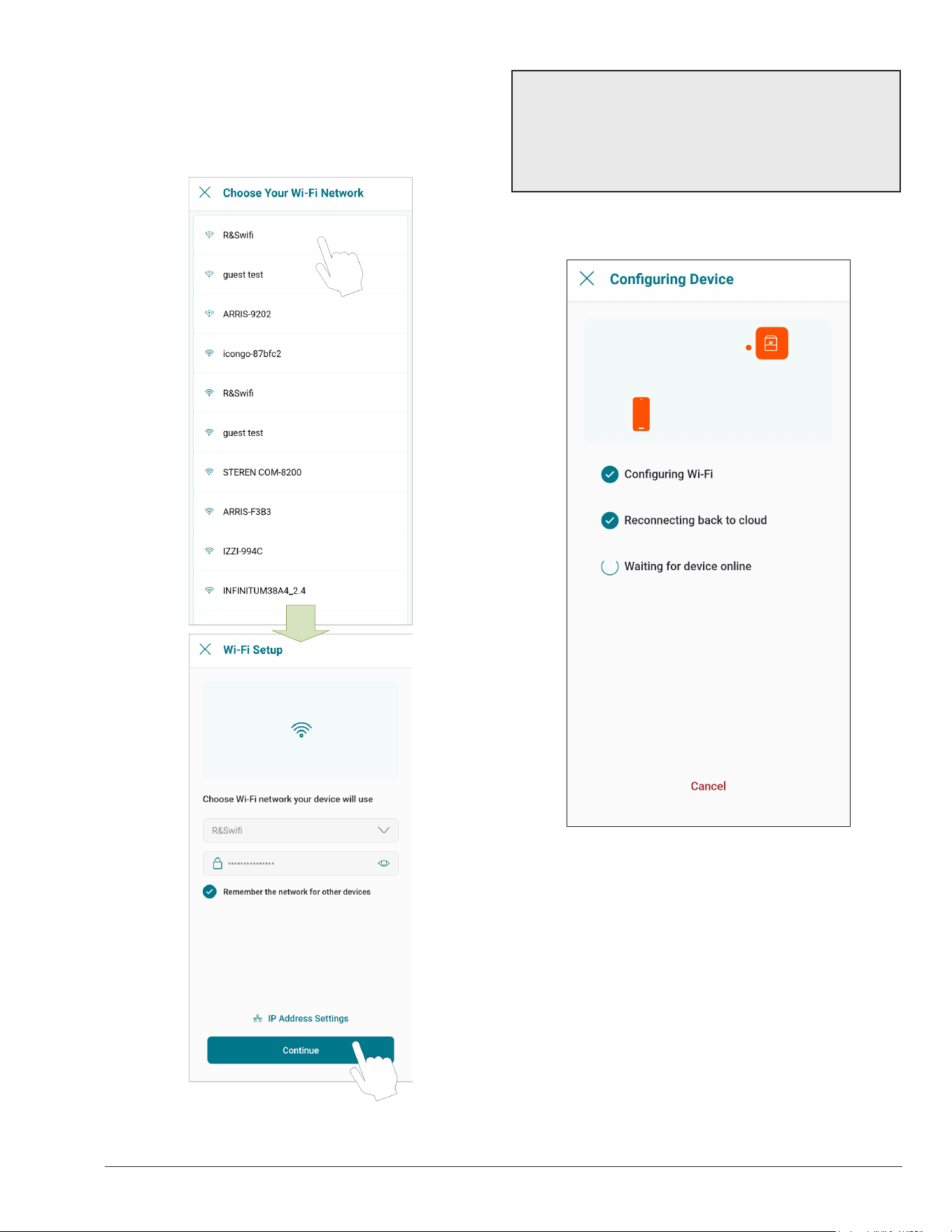
49
5. The "Wi-Fi setup" screen will appear. Select or enter
the Wi-Fi network you want your unit to be connected
to and enter the network password. See Figure 82.
6. Press the "Continue" button to proceed with unit
connection.
Figure 82. Wi-Fi Setup
IMPORTANT: Raymote Wi-Fi module works with 2.4GHz
Wi-Fi signals only.
Ensure to have a strong signal near the heater, the Wi-Fi
password and to use a 2.4 GHz network.
(IEEE 802.11, 802.11b/g/n/ax).
7. Raymote app will provide the Wi-Fi credentials to
your unit. This process may take a few seconds. See
Figure 83.
Figure 83. Conguring Device
8. Continue on page 50 to setup Crosswind V Heater.
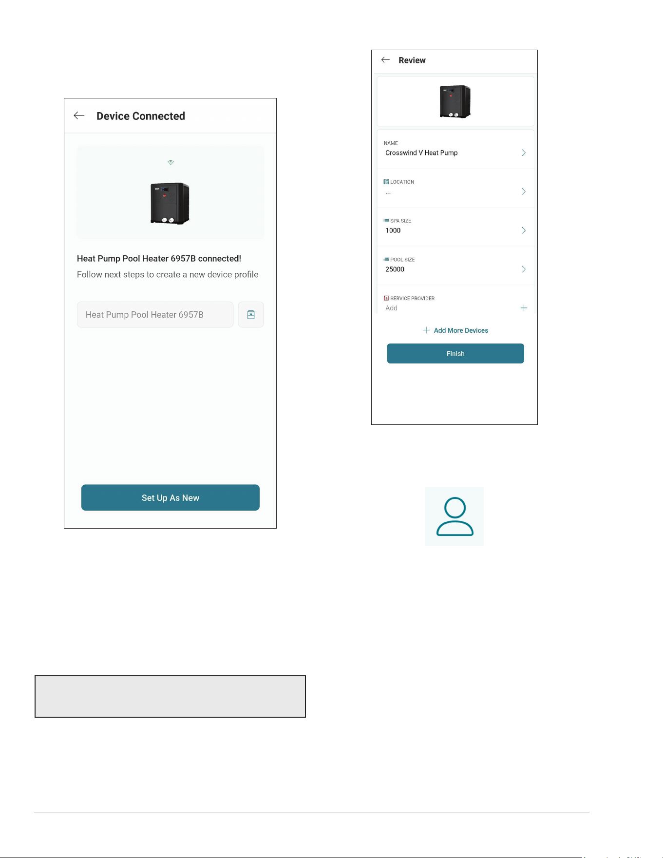
50
Crosswind V Heater Setup
1. Your device is now connected to Wi-Fi. You can
change the name of your device here. See Figure 84.
Crosswind V
Crosswind V connected!
Figure 84. Name Your Unit
2. Press the "Set up as new" button to enter heater
location, and other helpful info for future references.
Press the "Apply recently used profile" button to use
information previously applied to other heaters.
3. During device configuration, basic reference
information about the heater will be requested,
including service provider, site location, Pool and
Spa size. See Figure 85.
NOTE: This information can be added at any time from
the Raymote mobile app. It is strongly recommended to
make sure this information is completed.
4. After completing the Raymote configuration, the unit
will start broadcasting data to the Raymote cloud.
Figure 85. Device Setup Review
26. RAYMOTE MOBILE APP
User and Organization Settings
1. User profile:
• Update your username, email, or password.
• Edit or delete your Raymote account.
2. Raymote App settings:
• Adjust app preferences for notifications and
appearance.
3. Organization Settings:
• Review and Update your Raymote organization
settings.
• Add, edit, or remove Members with access to your
Raymote organization.
• For Raymote client accounts, share access to your
Raymote organization with a Contractor with an
active Raymote Partner account.
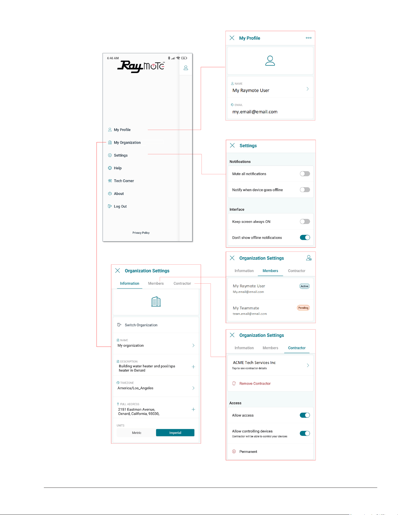
51
Figure 86. Settings - Client Accounts
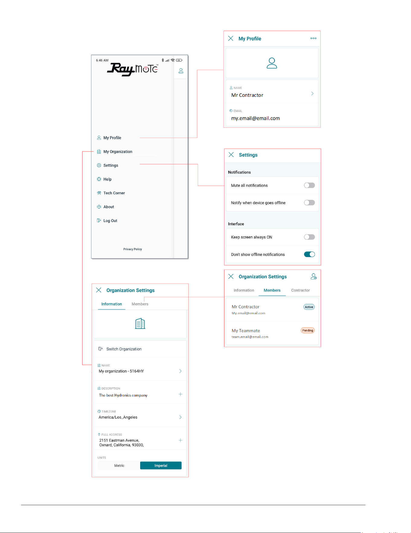
52
Figure 87. Settings - Partner Accounts
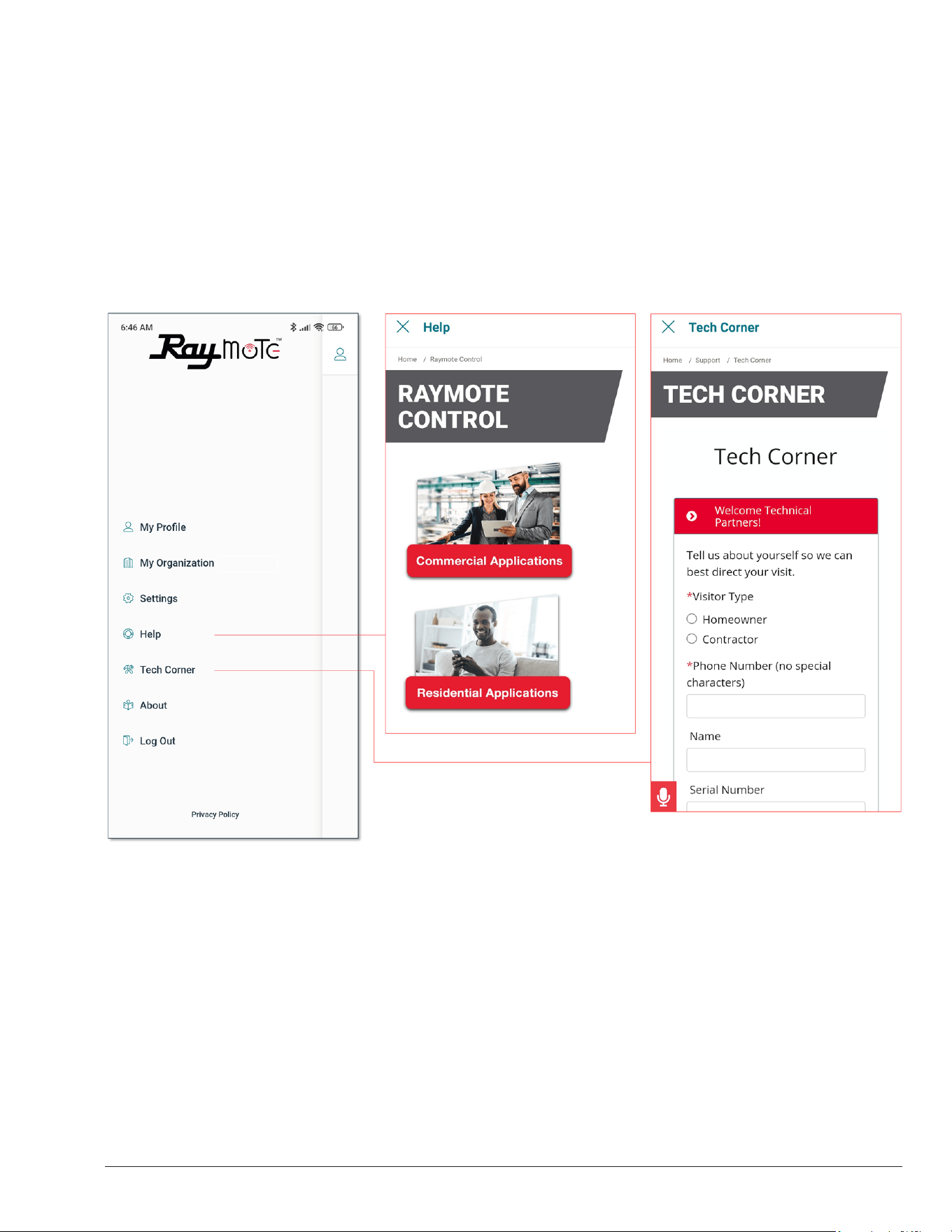
53
Help and Tech Support
Raymote app provides direct access to technical support
for Raypak heaters, service kits, I&O manuals and
Raymote topics:
1. Raymote Help:
• In-App access to Raymote Online resources and
technical contents.
2. Tech Corner:
• In-App access to Raypak Tech Corner collection.
You can find here detailed instructions for Raypak
products and service kits. See Figure 88.
Figure 88. Help and Tech Support
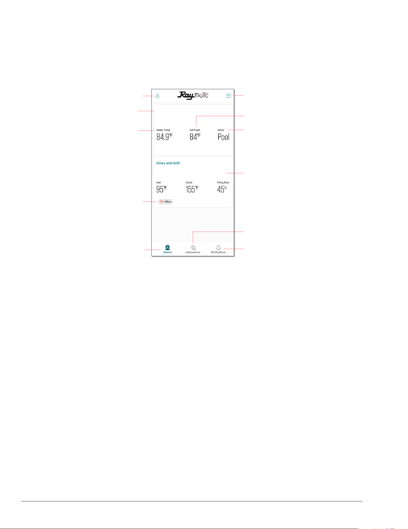
54
Main View
• The main view of Raymote display a list of the heaters
added in to your Raymote Organization.
• Each heater is represented by a tile with its name and
an overview of the heater operation parameters.
USER AND ORGANIZATION
SETTINGS
ADD HEATERS AND
SORTING
HEATER LIST CAN
INCLUDE COMMERCIAL
HEATERS
OPENS NOTIFICATIONS
SCREEN
OPENS AUTOMATION
SCREEN
HEATERS SCREEN
HEATER OFFLINE
INDICATOR
CURRENT WATER
TEMPERATURE
HEATER NAME
HEATER MODE
SELECTION
WATER TEMPERATURE
TARGET
Crosswind V Heat Pump
Figure 89. Main View - Heaters List
• Raymote organization list can handle 1 or multiple
Commercial and Residential Raypak heaters
equipped with Raymote. See Figure 89.
Heater Name
• Heater name is defined during the heater connection
and setup, but it can be changed anytime from the
heater settings.
Water Temp
• The water temperature measured by the heater is
displayed in this field. Water Temp variates with the
ambient temperature, pumps and heater's operation.
Setpoint
• Setpoint is the goal temperature for the heater. It can
be adjusted from the Crosswind V control board or
directly from Raymote.
• Heater start a call-for-heat when Water Temp is 1
degree Fahrenheit or more, below the setpoint and
operation Mode is POOL or SPA.
• In heat/cool models, Pool cool mode, heater starts to
cool when water is 1°F above temperature setpoint.
• In heat/cool models, Pool auto mode, heater starts to
cool when water temp is above temperature setpoint
+ cooling deadband. In this mode, unit call-for-heat if
water temperature is 1°F below temperature setpoint.
• Heater terminates heat when Water Temp is equal or
greater the setpoint temperature, or when Mode is
changed to OFF.
Mode
• Mode field displays the current operation mode
selected.
• POOL mode use an independent setpoint. Heat/
Cool models include POOL COOL and POOL AUTO
modes.
• SPA and TIMED SPA modes use an independent
setpoint.
• In OFF mode the heater is operational but is
maintained in standby until mode changes to POOL
or SPA.
Ofine Indicator
• The offline indicator is displayed only when the heater
can not be detected online.
• Offline status can be cause by a heater disconnected
from power, Wi-Fi signal weak or not available, or
due to any change in Wi-Fi signal name or password.
• Check the Connectivity Troubleshooting section for
details on how to recover or reconnect a heater to
Raymote.
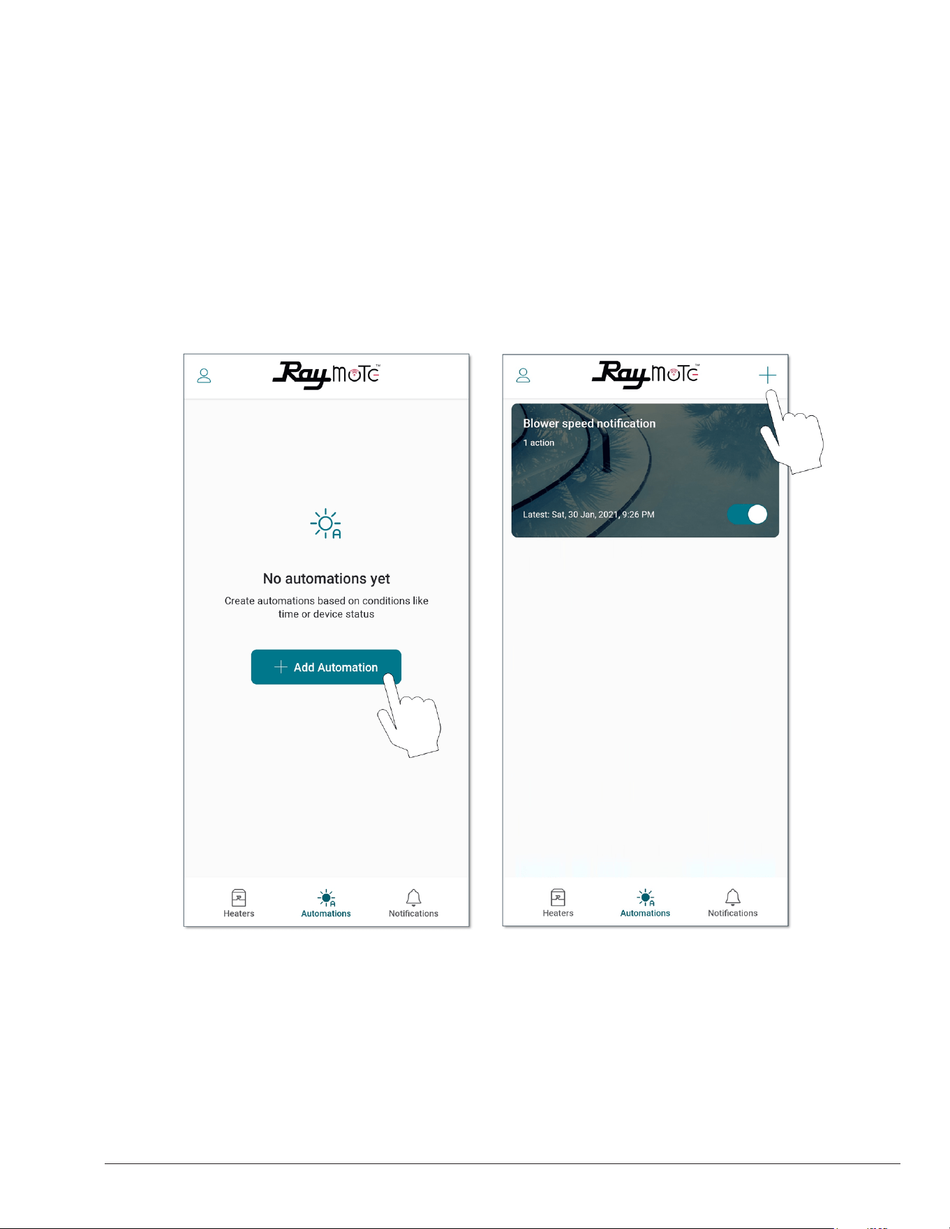
55
Automation
Raymote automation offers the ability to create automatic
routines to control the heater and compatible devices like
pumps and valve actuators. For details about compatible
devices refer to section 27, "Optional Control Outputs", on
page 73. See Figure 90 and Figure 91.
Figure 90. Automation
ADD THE FIRST AUTOMATION ADD MORE AUTOMATIONOR
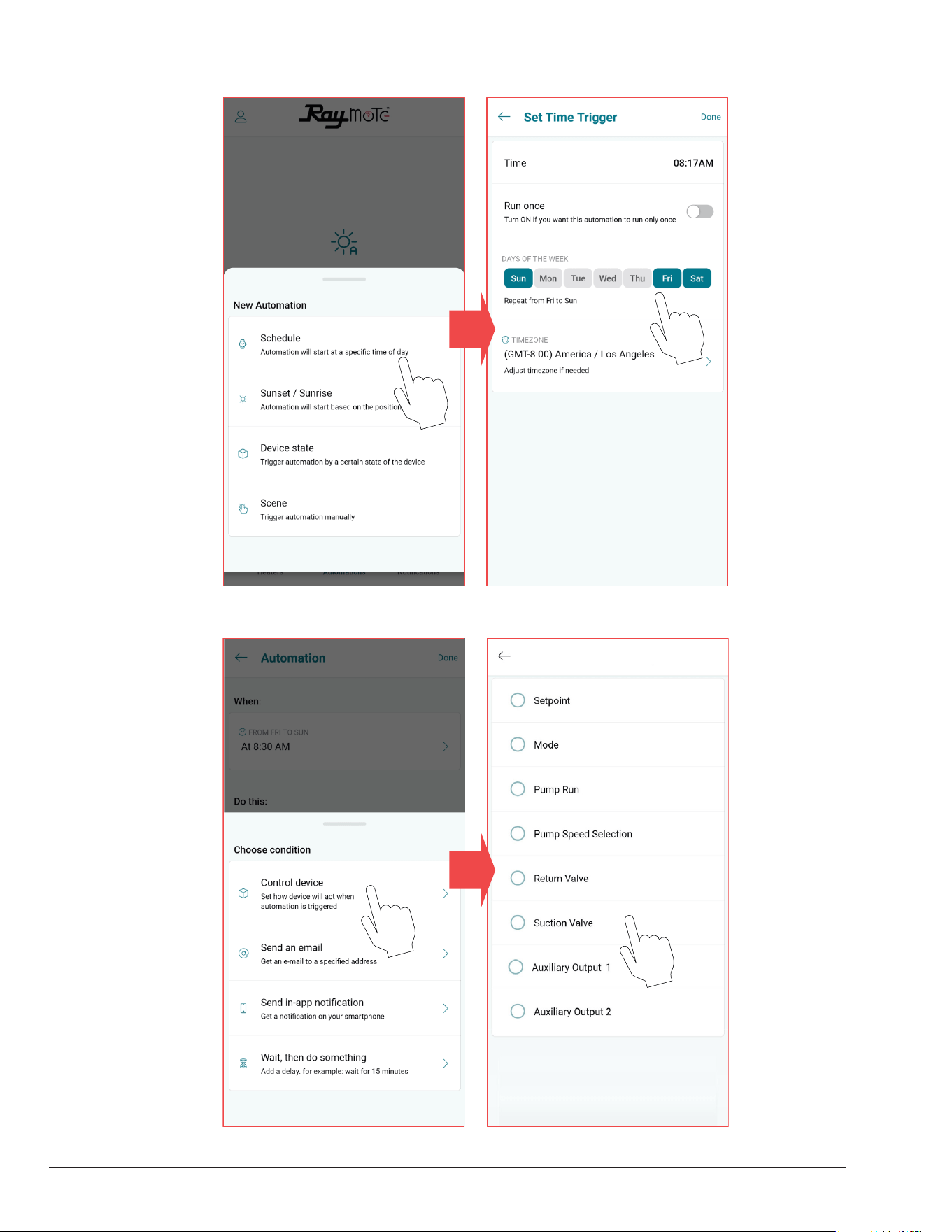
56
Figure 91. Set New Automation
SELECT A TRIGGER CONFIGURE TRIGGERING
SELECT AN ACTION CONFIGURE THE ACTION
Crosswind V Heat Pump
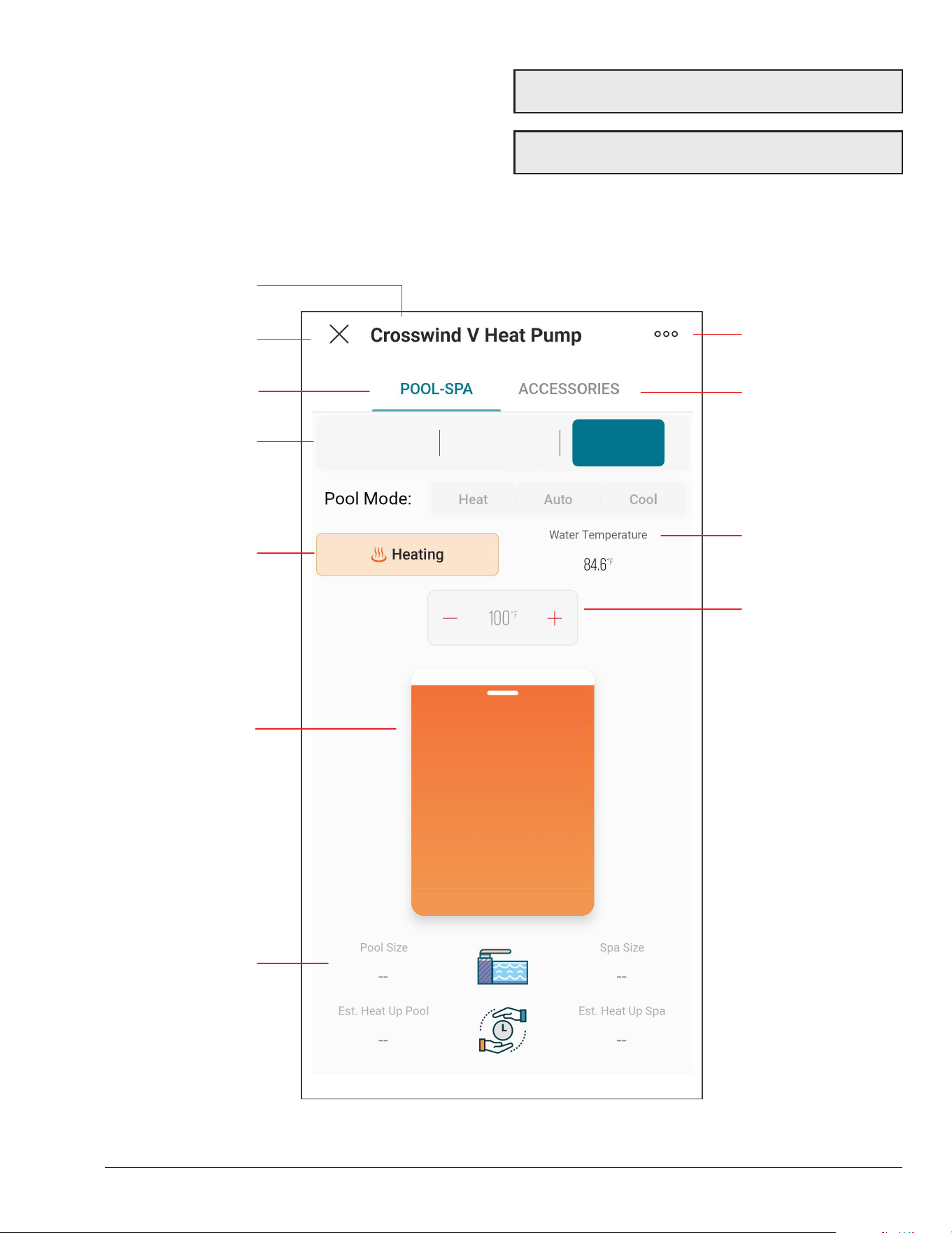
57
Pool-Spa Screen
The Mode Screen contains the main controls for the
heater. Operation mode and setpoint can be selected from
this screen.
This screen also provides the water temperature sensed
by the heater, as well as its current operation status. See
Figure 92.
Figure 92. Crosswind V Controls
OPERATION MODE
SELECTOR
POOL-SPA PAGE
WATER
TEMPERATURE
HEATER STATUS
EXIT HEATER
HEATER SETTINGS
POOL AND SPA SIZE
& HEATING TIME
ESTIMATION
HEATER NAME
WATER
TEMPERATURE
TARGET DISPLAY
AND SELECTOR
WATER
TEMPERATURE
TARGET SELECTOR
ACCESSORIES PAGE
Off Pool Spa
NOTE: When OFF is selected, the setpoint slider is
disabled.
NOTE: When unit is controlled with remote mode, the
buttons OFF, Pool and Spa are disabled in the App.

58
Heater Name
• Heater name is defined during the heater connection
and setup. It can be changed anytime from the heater
settings.
Exit Heater
• Press X to close heater view and return to heater's list.
Heater Settings
• The 3-dot icon opens heater settings.
• Use this option to edit the parameters defined during
heater configuration.
POOL-SPA page
• Displays the page to control the operation mode and
water temperature target.
ACCESSORIES page
• Displays the page to control heater accessories.
Operation Mode selector
• This 3-button selector can be used to change the
operation mode in the heater.
• Use OFF option to stop heating. In this mode the
heater is operational but is maintained in standby until
mode changes to POOL or SPA.
• Use POOL or SPA mode to set a water temperature
target.
• POOL and SPA mode use an independent temperature
target for each mode.
• Pool mode selector is enabled in Heat/Cool models.
Heater Status
• This display shows the current operational status of
heater.
• No Demand is displayed when the unit is in OFF mode
or when Water Temperature is equal or above the
temperature target.
• Heating is displayed when the unit is heating. In Heat/
Cool models, Cooling is displayed when pool cool or
pool auto is selected and the unit is cooling.
Water Temperature
• The water temperature measured by the heater is
displayed in this field.
Setpoint or Target Temperature
• The water temperature setpoint display and selector
shows the water temperature target.
• Heater start to heat when Water Temperature is 1
degree Fahrenheit or more, below the setpoint and
operation Mode is POOL or SPA.
• Heat/Cool models, Pool Cool mode: Heater starts to
cool when water temperature is 1F or more above the
setpoint.
• Heat/cool models, Pool Auto mode: Heater starts to
cool when water temperature is above the temperature
setpoint + cooling deadband. Heater start to heat
when Water Temperature is 1 degree Fahrenheit or
more, below the setpoint
Setpoint slider selector
• The setpoint slider can be used to make quick changes
to the water temperature target.
• Selection can be fine-tuned with the [+] and [-] buttons
in the setpoint display and selector.
Pool and Spa size
• The Pool and Spa size displays shows the size
selected in the configuration of the heater when
connected to Raymote.
• These parameters can be updated from the Heater
Settings page.
Pool and Spa estimated Heat up time
• These fields displays an estimated heat up time
based in the provided Pool and Spa size, the current
water temperature, the water target temperature and
ambient temperature.
• Technical restrictions apply to this estimation.
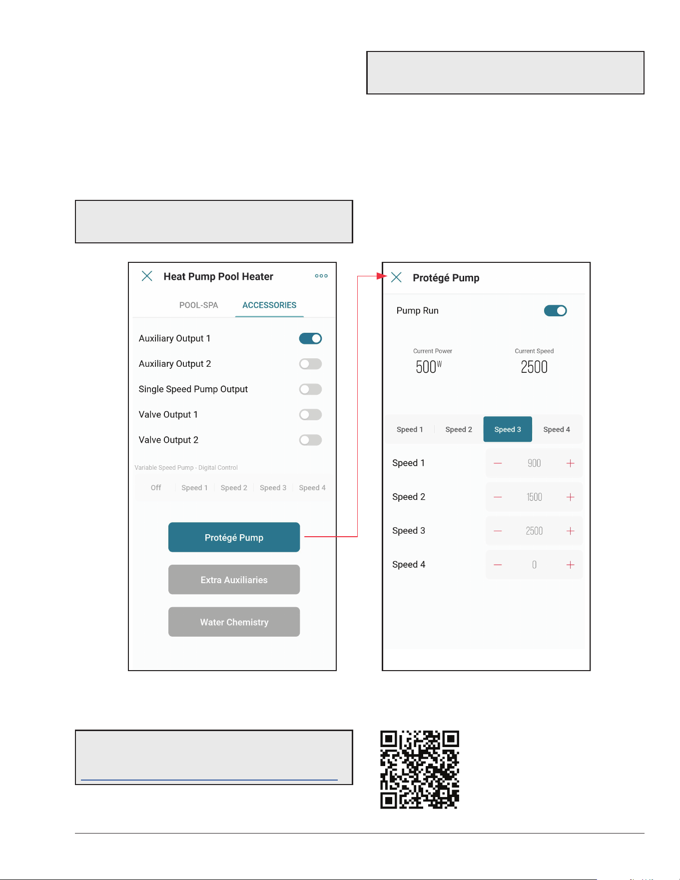
59
Accessories Screen
The accessories screen includes the auxiliary and
extended heater controls in the Raymote mobile app.
These controls allow users to command an Auxiliary relay
that can be wired to turn on and off a pump, lights or water
features.
This screen also provides control to Raypak Protege
variable-speed pump when connected to the heater. See
Figure 93.
Figure 93. Crosswind V Accessories
A
WARNING: Only authorized users have access to
remotely control the heater, do not provide access to
unauthorized users.
NOTE: Check Section 27 "External Control Outputs"
section for details of wiring and rating of the built-in
auxiliary relay.
Some controls are application dependent and may not be
available on all units. When a control or set of controls are
not available, these will be grayed out.
Raymote controls will reect the actual status of the value
on the local unit. When a change is applied to any control
item, the position of the selector will reect the conrmation
value of the setting. See Figure 93.
NOTE: Use your smartphone camera to open QR link
below to access the latest instructions and detailed
technical support for Raymote and Crosswind V:
https://www.raypak.com/support/tech-corner/raymote/
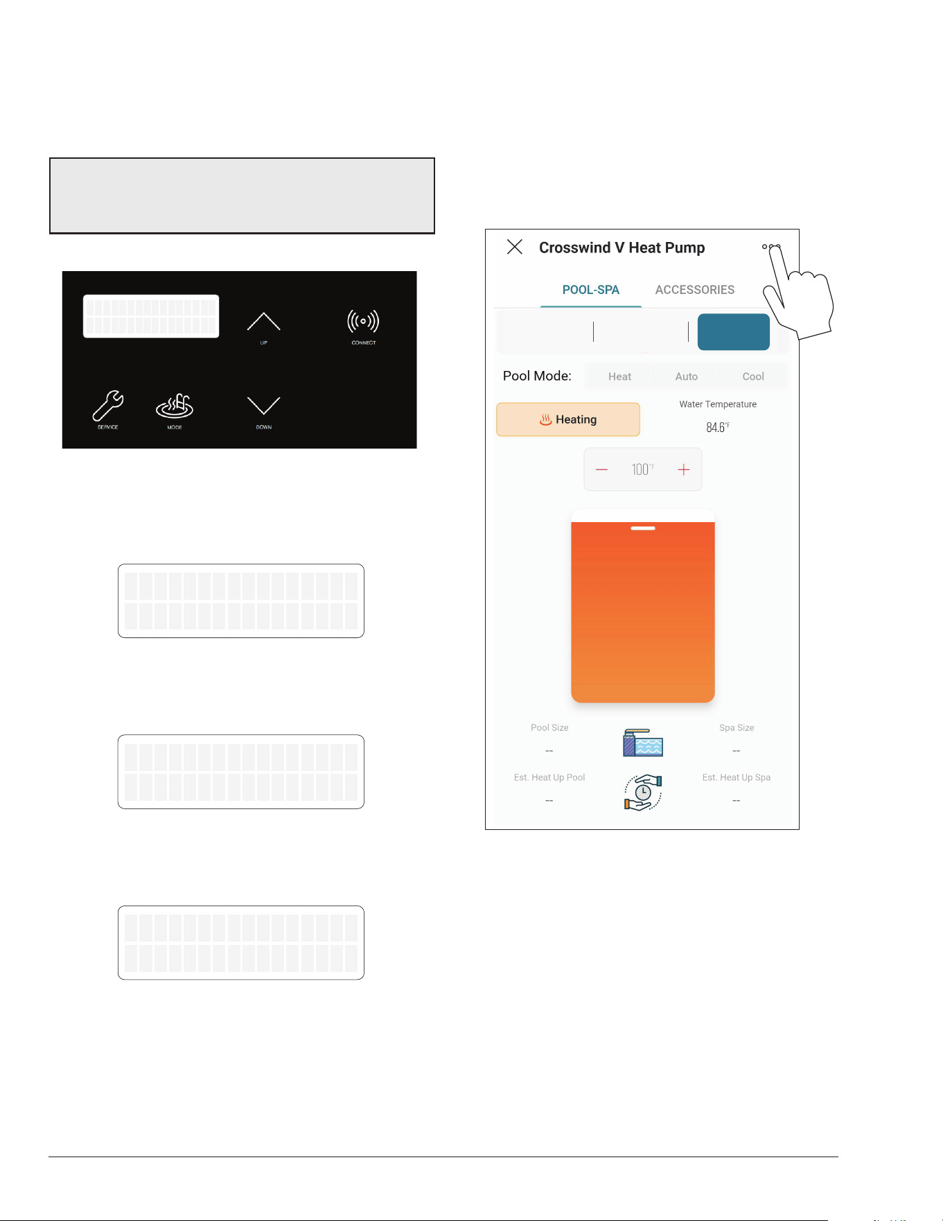
60
Reset Wi-Fi Credentials
Resetting the Wi-Fi is useful when the heater is trying to
connect to a Wi-Fi signal that is not available or has been
changed. See Figure 94 through Figure 97.
NOTE: After resetting Wi-Fi credentials, the heater
needs to be manually connected again to Wi-Fi to work
with Raymote features. Ensure to reconnect as existing
unit in Raymote app or add it as a new device.
1. Press and hold the CONNECT key for 5-seconds.
OFF
Water Temp 68F
Figure 94. Wi-Fi Reset – Press and Hold CONNECT
2. The display shows “Reset Wi-Fi?” In the top row and
“No” in the second row.
3. To cancel and exit, press MODE.
Reset WiFi?
No
Figure 95. Wi-Fi Reset Menu
4. To proceed with reset, press UP key.
5. Second row now shows “Yes".
Reset WiFi?
Yes
Figure 96. Wi-Fi Reset Conrmation
6. Now press Mode key to reset.
7. “Wi-Fi Initialized” message is displayed.
WiFi Initialized
Figure 97. Wi-Fi Reset Completed
8. Now connect again or re-configure an existing heater.
Reconnect to Wi-Fi
Follow the next steps to reconnect a heater already
registered in Raymote, to a new Wi-Fi network or after a
change of Wi-Fi password.
1. Select the device that needs to be reconfigured.
2. Press the 3-dots button on top-right corner to open
unit settings. See Figure 98.
Off Pool Spa
Figure 98. Open Unit Settings
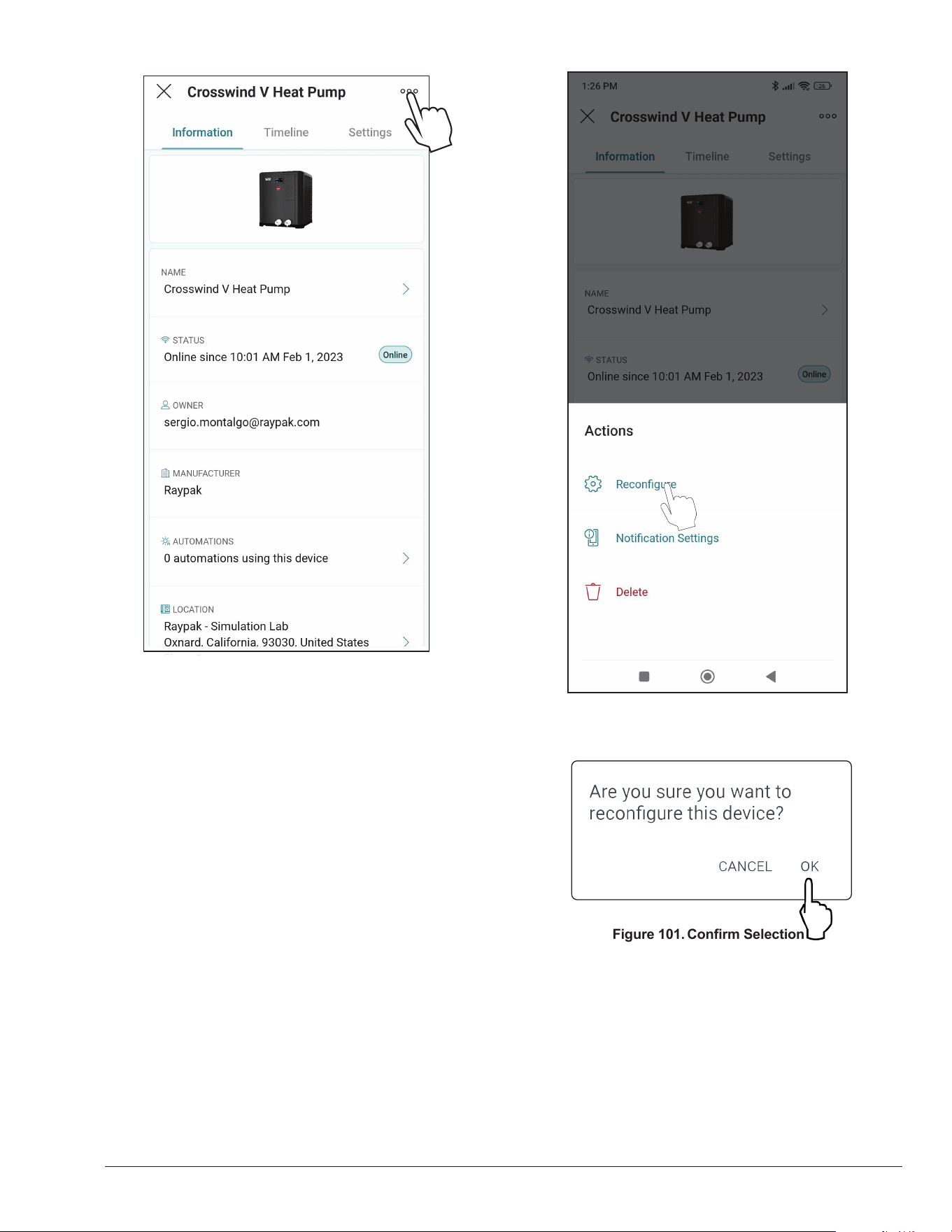
61
Figure 99. Heater Settings Screen
3. Click in the 3-dots icon again. The action menu is
displayed. In “Actions” menu, select the option
“Reconfigure” as shown in Figure 100.
Figure 100. Select Recongure
Figure 101. Conrm Selection
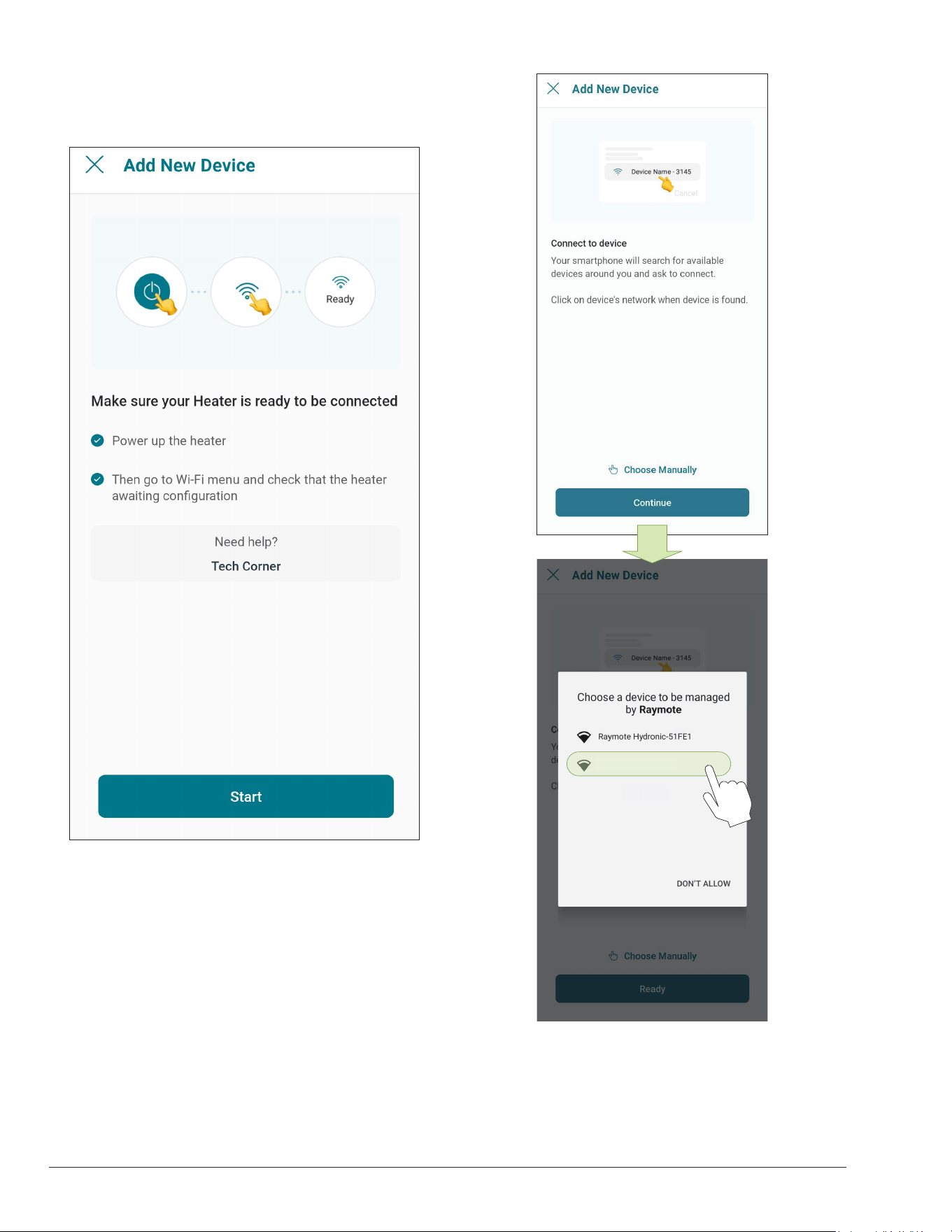
62
4. "Check your Device" screen will appear. Ensure to
have the heater powered and Wi-Fi signal available
in the area, then press "Ready" button. See Figure
102.
Figure 102. Check your Unit
5. In Android: Depending on your configuration, one
or more devices will appear on the app. Select the
HOTSPOT identifier that matches the unit's display
as shown in Figure 103.
Raymote HPPH-XXXXX
Figure 103. Connect with Android Smart Phone
6. In iPhone: Raymote app will start to scan nearby
heaters. If you have multiple units ready to connect,
stand closer to the unit you want to connect first.
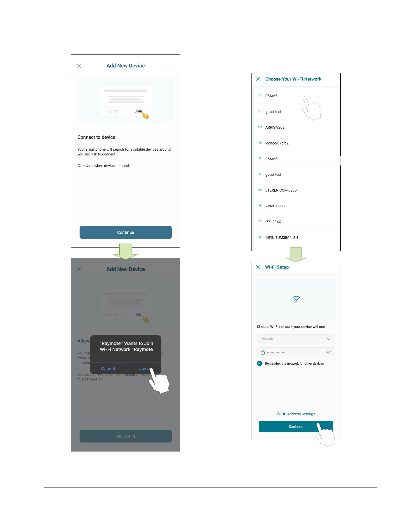
63
Press "Join" to select the displayed heater that
matches the HOTSPOT identifier, or press "Cancel"
to start the process again. See Figure 104.
HPPH-XXXXX?
Figure 104. Connecting with iPhone
7. The "Wi-Fi setup" screen will appear. Select or enter
the Wi-Fi network you want your unit to be connected
to and enter the network password. See Figure 105.
8. Press the "Continue" button to proceed with unit
connection. See Figure 105.
Figure 105. Wi-Fi Setup
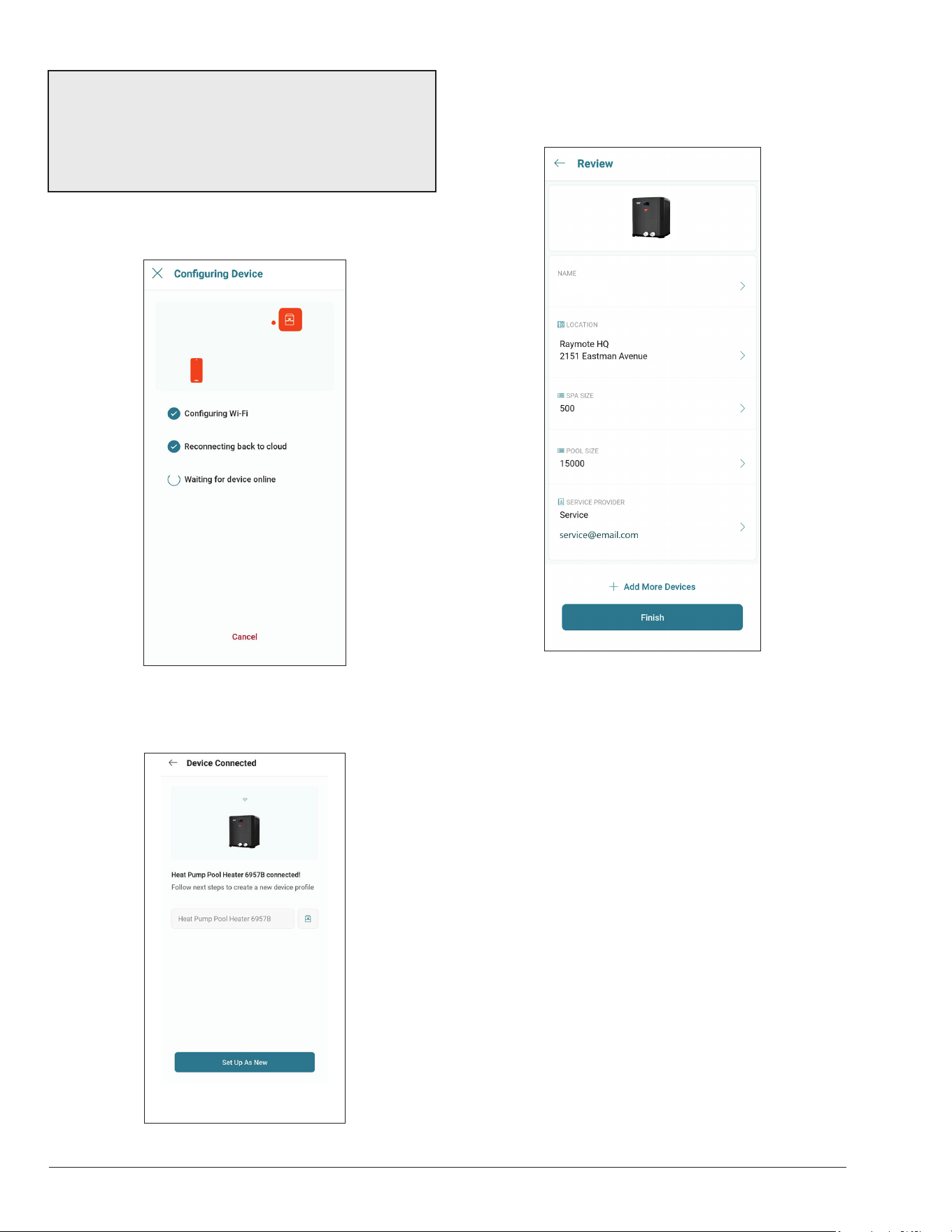
64
IMPORTANT: Raymote Wi-Fi module works with 2.4GHz
Wi-Fi signals only.
Ensure to have a strong signal near the Heater, the Wi-Fi
password and to use a 2.4 GHz network.
(IEEE 802.11, 802.11b/g/n/ax).
9. Raymote app will provide the Wi-Fi credentials to
your unit. This process may take a few seconds. See
Figure 106.
Figure 106. Conguring Device
10. Your device is now connected to Wi-Fi. You can
change the name of your device here. See Figure 107.
Figure 107. Name Your Unit
11. Press the "Set up as new" button to enter unit
location, and other helpful info for future references.
Press the "Apply recently used profile" button to use
information previously applied to other heaters.
Crosswind V connected!
Figure 108. Device Setup Review
12. After completing the Raymote configuration, the unit
will start broadcasting data to the Raymote cloud.
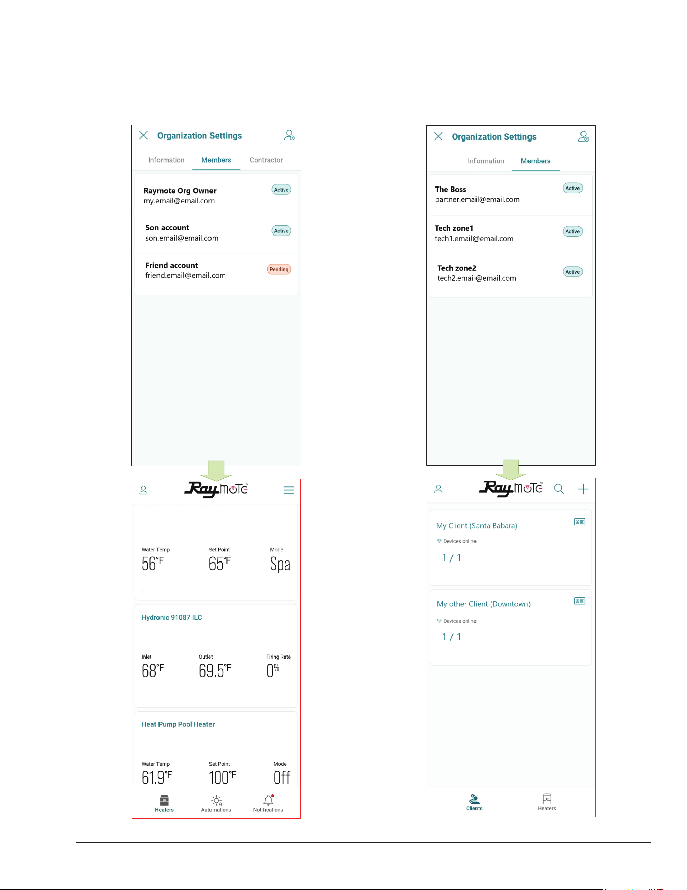
65
Crosswind V Heat Pump
Add a New User to your Organization
• As the Organization owner, you can add members of
your family, friends and others that will be able to interact
with your heaters. See Figure 109.
Figure 109. Organization Members Share Access to Heaters Figure 110. Partners Accounts with Multiple Clients
• In Raymote Partner accounts, you can add members
of your company to gain access to heaters and clients
registered within your Organization. See Figure 110.
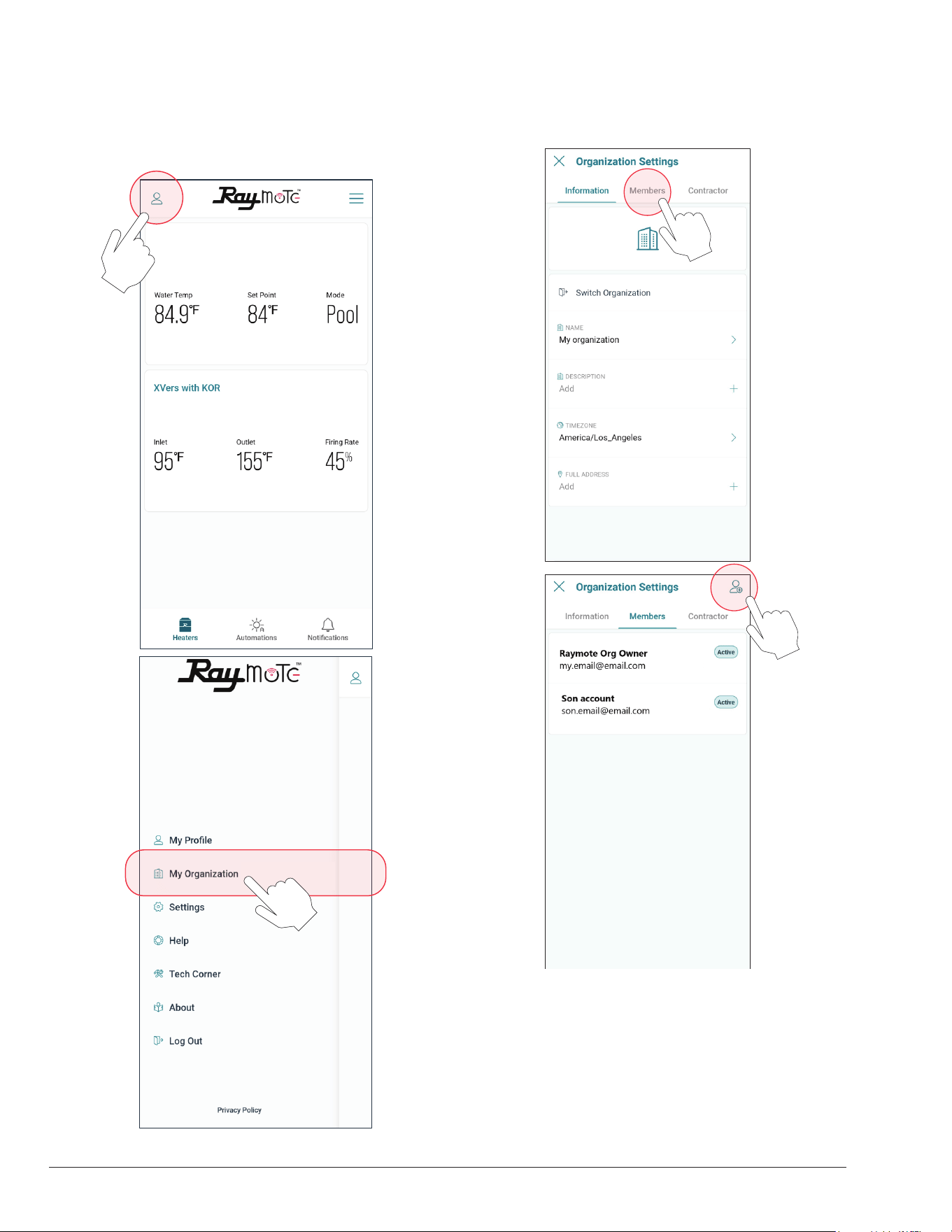
66
Crosswind V Heat Pump
Figure 111. Select Organization Option
Figure 112. Invite a New Member to your Organization
Add a Member to your Organization
1. In your smartphone, open the Raymote app.
2. Click on the top-left "User menu". Then, select "My
Organization" option. See Figure 111.
3. Go to "Members" tab. Member’s list is displayed.
4. Click on the top-right icon to [Invite a New Member].
See Figure 112 and Figure 113.
5. Fill the invitation with new member's email, name,
and role. Based on your selection, the new member
can have different permits in your organization.
6. Click in the top-right icon to complete and send the
invite. An email will be sent to the New Member
to create a new Raymote user associated to your
organization.
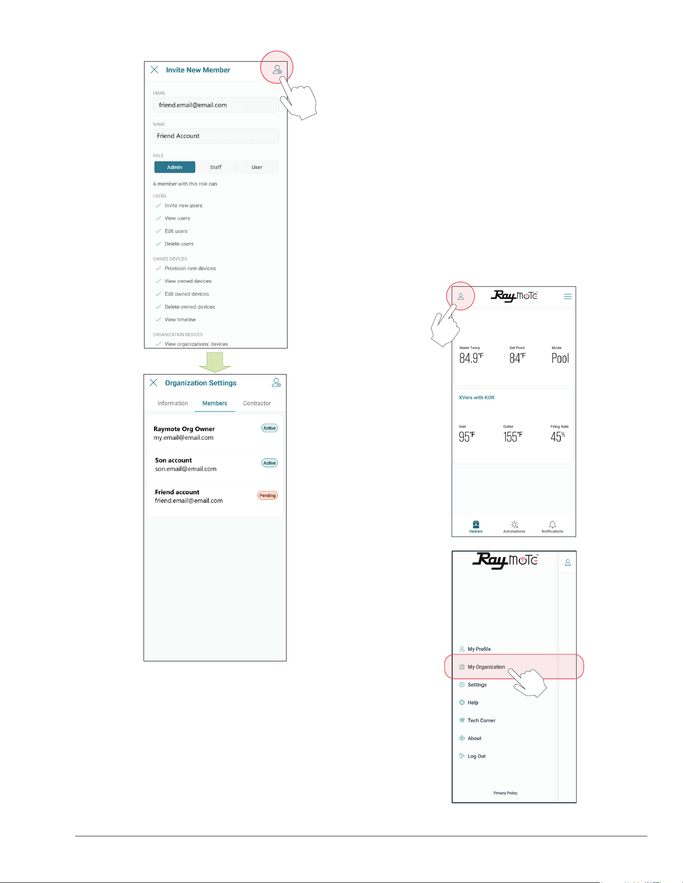
67
7. IMPORTANT: To complete the invitation, the
new member needs to create a password from
Raymote email invitation, to access your Raymote
Organization.
Figure 113. Invite a New Member
Client Accounts: Invite a Contractor
By inviting a Contractor or Distributor, you are giving
access to heaters available in your organization to a third-
party organization.
You can condition the access to your invited contractor as
follows:
• For monitoring only.
• To monitor and control your heaters.
o Access can be permanent or restricted
to a certain period.
1. In your smartphone, open Raymote App.
2. Click on top-left "User menu".
3. Then, select "My Organization" option. See Figure
114.
Crosswind V Heat Pump
Figure 114. Select Organization Option
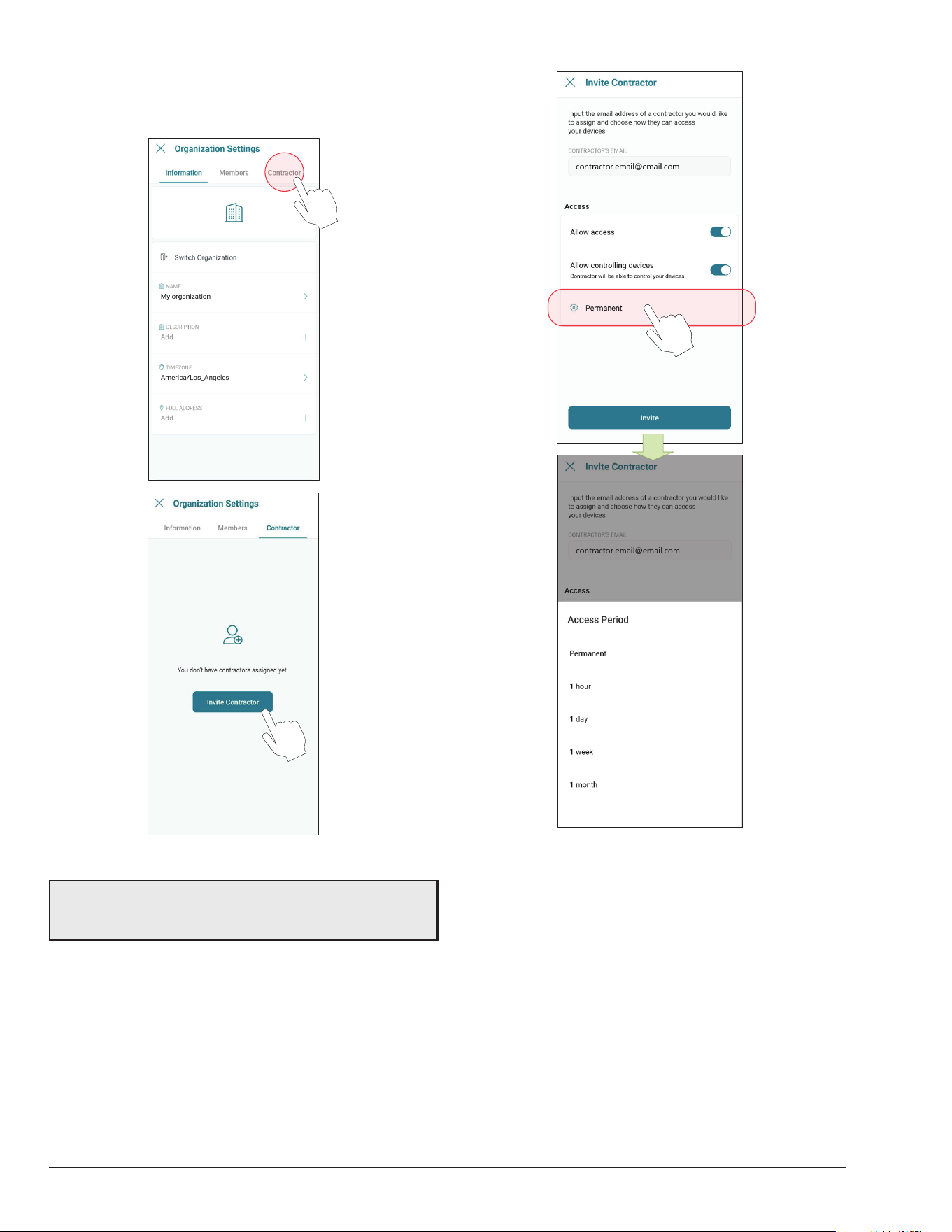
68
Figure 115. Click on “Invite Contractor”
Figure 116. Enter Contractor Email and Access Level
4. Organization Settings page is displayed.
5. Go to [Contractor] tab, and press [Invite Contractor].
See Figure 115.
6. Add your contractor’s email and select the access
options as needed. See Figure 116:
• Allow Access - Allows the contractor to monitor your
heaters.
• Allow Controlling Device - Contractor can make
changes to your heater conguration and create
automation routines.
• Access Period - Denes for how long the contractor
can monitor or interact with your heaters.
7. When ready, press [Invite]. An invitation/request will
be sent to the contractor's Raymote account. See
Figure 117.
8. IMPORTANT: To complete the invitation process ask
your contractor to accept the request directly from
their Raymote App account.
9. When done, you can always edit the permissions,
remove the contractor, or cancel the invitation in
Organization’s settings, [Contractor] page.
IMPORTANT: Contractor must have an active Raymote
“Partner” account to be able to connect your account
with the contractor’s account.
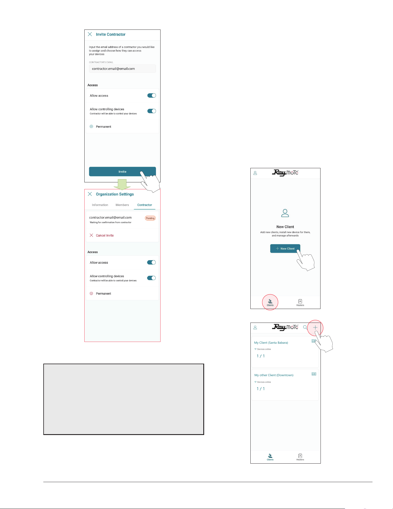
69
Figure 117. Send the Invite
NOTES:
•“Invite a contractor” option is only available for Raymote
Client accounts.
•Contractor must have a Raymote partner account to get
requests from client accounts.
•Raymote partner accounts can invite only new clients
to Raymote. If the client already has a Raymote account,
ask the client to send a request from “Contractor” option.
Partner Accounts: Invite New Clients
With a Raymote Partner account, “Contractor” or “Distributor”,
you can:
• Invite and "Manage New Clients"
• Connect and congure your clients' heaters
• Monitor and control residential and commercial
heaters
• Create automation routines and alerts for your clients
• Invite members to your organization
1. In your smartphone, open Raymote app.
2. Click on bottom-left [Clients] icon.
3. Now, press [New Client] button or top-right [+] icon.
See Figure 118.
OR
Figure 118. Add a New Client
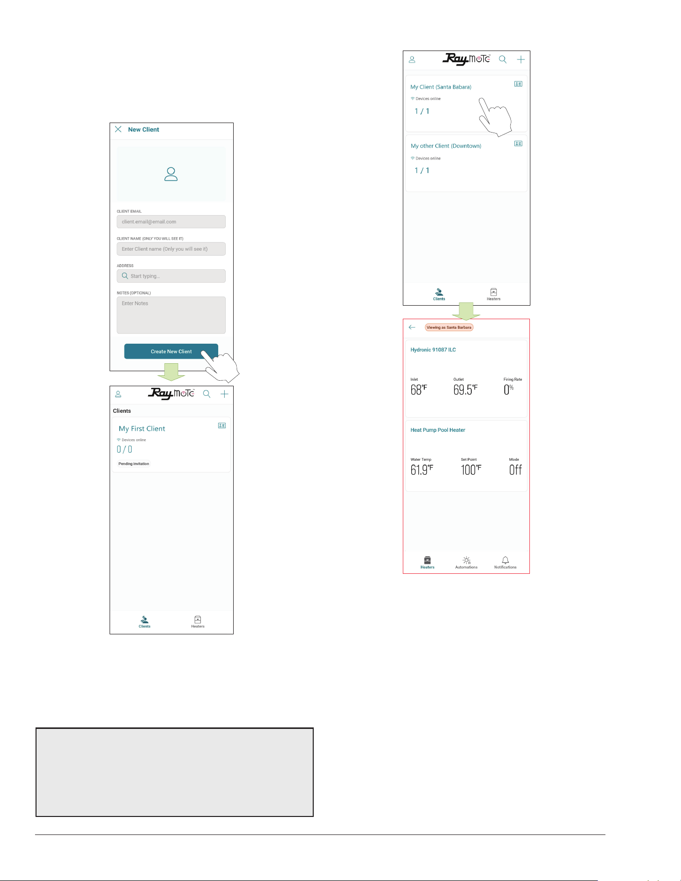
70
Figure 119. Enter Client Email and Invite
4. Fill "New Client" form with your client's email, name,
and address.
5. When ready, press [Create new client]. An Raymote
invite email will be sent to your new client. See Figure
119.
6. Ask your Client to create a new Raymote account
from the email invite.
7. You can access your client's heaters by clicking in
each client tile. See Figure 120.
OR
Figure 120. Access your Client's Heaters
NOTES:
•“Add New Client” option is only available for Raymote
partner accounts.
•Raymote partner accounts can invite only new clients
to Raymote. If the client already has a Raymote account,
ask the client to send a request from “Contractor” option.
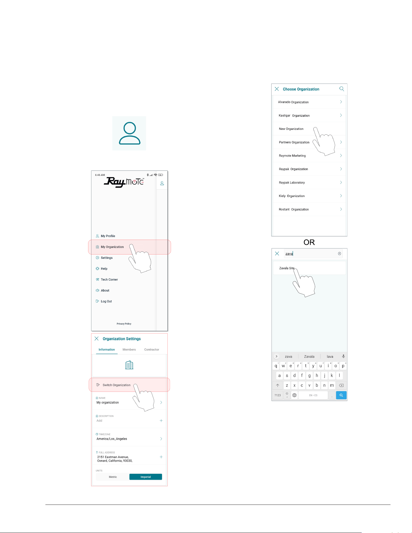
71
Switch to Other Organizations
If your Raymote organization has 1 or more sub
organizations, you can switch to other organization by
using the "Organization" tree or search function.
1. Open the main menu by clicking the top left icon. See
Figure 121.
2. On the main menu, click on the “Organization” option.
See Figure 122.
Figure 121. User Menu
Figure 122. Switch Organization
Figure 123. Choose Organization
3. In "Organization Settings" page, select "Switch
organization" option. See Figure 122.
4. “Choose organization” screen will be displayed and it
will show all the available organizations. Navigate the
sub-organization list or use the search tool to locate
desired organization. See Figure 123.
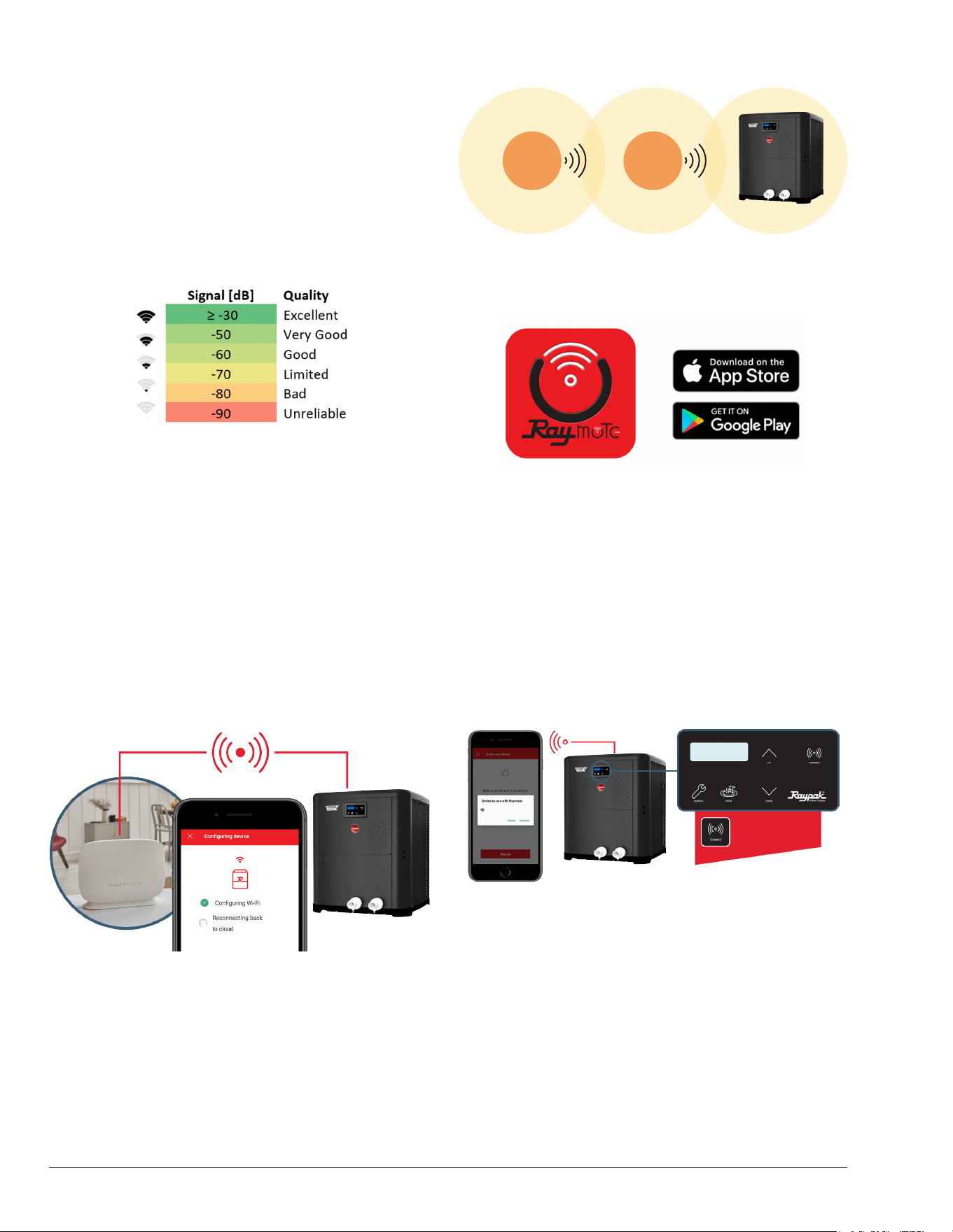
72
Connectivity Troubleshooting
1. With your cellphone check that Wi-Fi signal is
available next to the unit. Ensure that your Wi-Fi
network meets these specifications:
• Supported networks - Wi-Fi 2.4GHz (802.11 b/g/n).
• Password encryptions - WEP, WPA, WPA2.
• Wi-Fi signal icon of 2 bars (-60dB) or better at heater
location. See Figure 124.
Figure 124. Wi-Fi Signal
Figure 125. Reset Wi-Fi Credential
2. Use the built-in Wi-Fi network options in your
cellphone or use a Wi-Fi network scanner app, like
Fing Network Scanner for iPhone or Wi-Fi Analyzer
for Android smart phones, to check signal strength.
If you are having troubles connecting your heater to
the Raymote app, try these common solutions:
• Check that Wi-Fi signal name and password are
correct.
• In case of a change, proceed to reset Wi-Fi credential
from heater touchscreen and reconnect the heater
with Raymote app. See Figure 125.
3. Check that your Wi-Fi signal strength is strong
enough to reach the heater.
• Reduce distance between Wi-Fi router and the
heater.
• Add a Wi-Fi range extender to cover heater zone or
enable a new Wi-Fi access point. See Figure 126.
Wi-Fi
Router
Wi-Fi
Extender
Figure 126. Wi-Fi Extender
4. Update Raymote app to the latest version.
Figure 127. Update Application
5. Power-cycle your heater and restart Raymote app.
6. Check the settings on your router or Wi-Fi access
point.
• If needed, enable a dedicated 2.4 GHz network.
5GHz signals are not compatible with Raymote.
• When applicable, ensure to have the permissions
from IT or Building Manager.
• Check if MAC address whitelisting is required.
• Check if Static IP is required. See Figure 128.
The CONNECT key
displays the ID and
connectivity status.
HPPH-6957B
Ready To Config
Raymote HPPH-6957B
Figure 128. Wi-Fi Access Point Settings
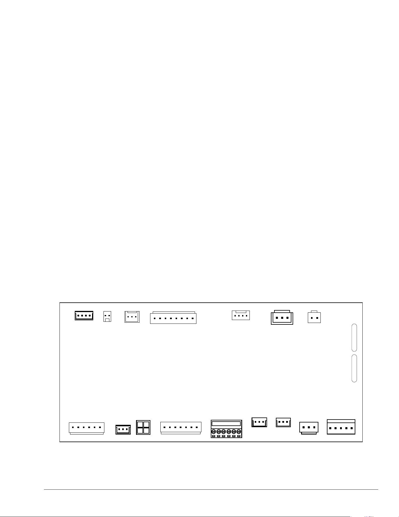
73
27. EXTERNAL CONTROL
OUTPUTS
Crosswind V heater controller offers multiple external
optional outputs designed to drive 2-valve actuators,
a single-speed pump, a variable-speed pumps and 2
auxiliary relay outputs for On/Off devices like blowers,
lights, or water feature actuators. The controller is also
equipped with an optional auxiliary input to enable
external fault or interlock. Additionally, the Crosswind V
controller provides built-in integration with solar heaters
allowing the heat pump controller to select or bypass
solar heater water supply.
The available optional inputs and outputs are listed below.
Refer to Figure 129 for the location of each terminal.
• Valve 1 and 2 Outputs [P19 and P20]. Standard
24VAC outputs to control 2-way or 3-way valve
actuators.
• Single-Speed Pump Output [P5]. Low voltage
(24VAC) output designed to command a single-speed
pump (or others on/off device). This output must be
used in conjunction with a field-supplied 24VAC relay.
• Protégé Variable-Speed Pump [P12]. Dedicated
communication port to control Raypak Protégé
variable-speed pumps.
• Digital Control Variable-Speed Pump [P8]. 5-pin
output to command variable-speed pumps compatible
with 30VDC digital signals for speed selection.
• Auxiliary 1 and 2 outputs. General purpose relay
outputs to control On/Off devices. These outputs do
not supply power. Use in conjunctions with external
power supply. Use additional field-supplied relays for
applications above 3 amperes.
• Auxiliary Input [P11]. The control provides an
optional auxiliary input that can be configured to
display and record a fault or to trigger an interlock
and inhibit heater operation.
• Remote control selector [P7]. The control provides
a standard 3-wire selector to work in conjunction
with external automation controllers. Please refer to
section 16 in page 30, for details about wiring and
configuration of remote mode selector.
• Solar Heater integration [P9 and P11]. The control
provides a 10K sensor input in P11 and a 24VAC
3-way valve standard output in P9 to integrate the
Heat pump operation with a solar heater.
• Water Flow Switch. Wiring instructions for
connecting the external Water Flow Switch within the
heater's electrical junction box.
The factory-default operation mode for these components
is disabled or set to be commanded from Raymote app.
• Refer to section 13, "Installer Menu", in page 21 to
set the operation mode of each terminal.
• Refer to section 14, "Schedule Menu" in page 25 for
details about the built-t local schedule.
• Please refer to sections 25 and 26 of the Raymote
app, for detailed instructions on how to connect the
unit to Wi-Fi and create online automation.
3A
3A
COMM
(RS-485)
P12
P13
P10
P6
P16
P7
REMOTE
SELECTOR
P1
F1
F2
VARIABLE
SPEED PUMP
P8
SINGLE
SPEED
PUMP
P5
P19P20
VALVE2
OUTPUT
VALVE1
OUTPUT
AUX 1 & 2
OUTPUTS
P4
P3
P11
P9
P2
FAN RVS COMP
SOLAR HEAT
& AUX INPUT
WPS LPS HPS
Figure 129. External Control Terminals
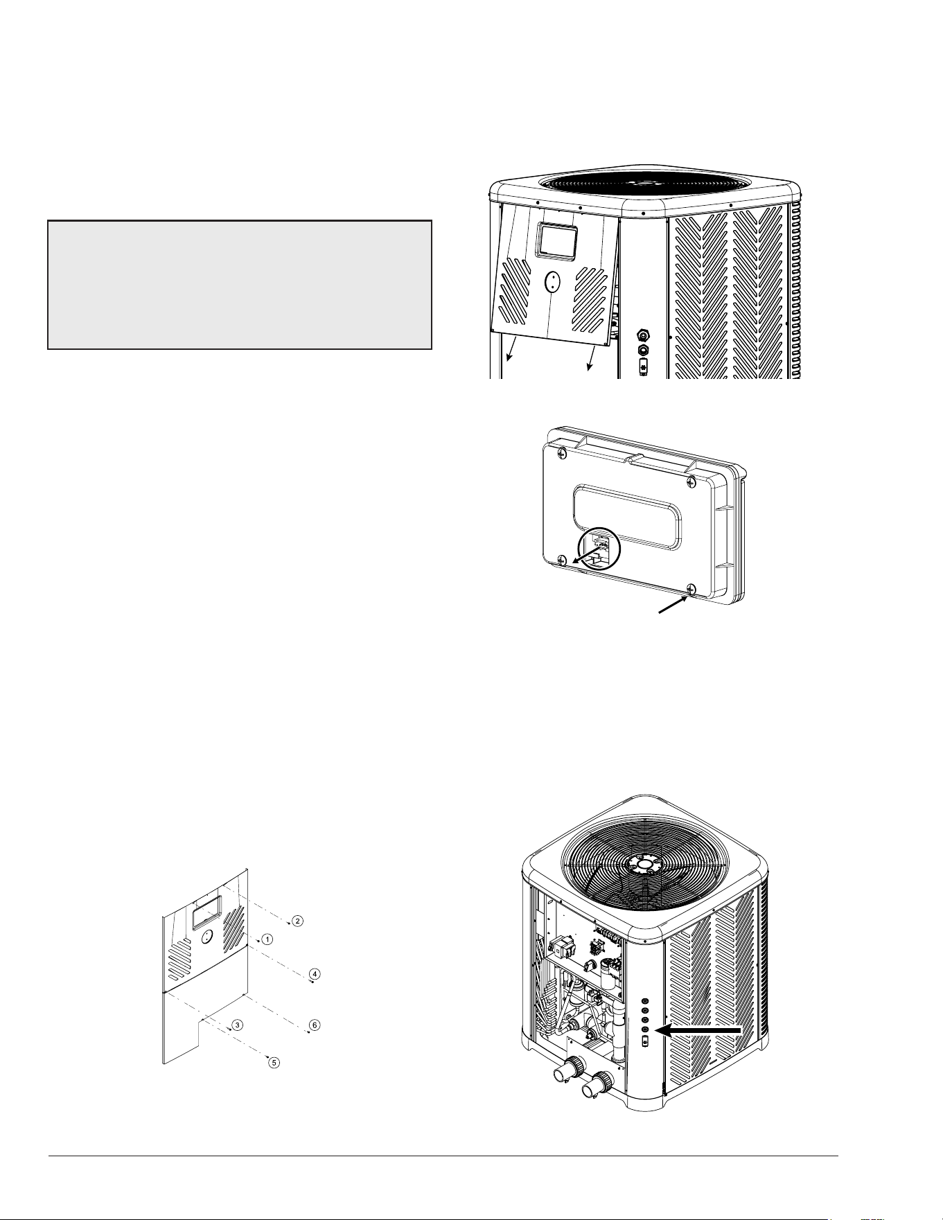
74
Instruction for Wiring
External Devices
This section outlines the general steps to wire the optimal
control outputs and inputs from the pool devices to the
heater control board. For more information about each
terminal, please refer to the section corresponding to each
optional terminal.
A
WARNING: To properly service this equipment, you
need to have a certain level of expertise, electric and
mechanical skills, and access to the necessary tools and
equipment. If you do not possess these requirements,
please do not attempt to perform any service on this
equipment except for the procedures recommended in
this manual.
Important installation notes for control
signals wiring:
• Before performing any electrical installation, make
sure to de-energize the heater.
• Control wires should be run in a separate conduit to
avoid interference with other wires.
• Use the grommet/knockouts available in the corner
post to route wires into the heater. Ensure that liquid-
tight connectors are used to prevent water or dust
intrusion.
• Low voltage wiring should not be run together with
high voltage lines.
• Use the appropriate relays for your application,
ensuring that the relay coil is compatible with the
external power supply. For the single-speed pump
output, use a 24VAC relay.
• Use the supplied accessory harness to connect to
terminals P4, P5, P7, P8, P9, and P11 on the heater.
1. Before starting any work on the unit, make sure to
shut off all power to avoid the risk of electrical shock or
damage to components.
2. To access the heater's front control cover panel, use
a 1/4" hex head screwdriver to unscrew the six (6)
screws. See Figure 130.
Figure 130. Sheet Metal Screws to Remove Control Panel
3. To remove the front panel, pull the bottom of the
panel downward and outward, and then disconnect
the wire attached to the rear of the user interface.
The panel should now be free for removal. See
Figure 131 and Figure 132.
PULL PANEL
DOWNWARD
Figure 131. Detach Front Panel
REMOVE TETHER WIRE FROM BOTTOM
RIGHT SCREW AND TRANSFORMER
UNPLUG TERMINAL FROM
DISPLAY
Figure 132. Remove Wiring from Display
4. Set the control panel cover aside to reinstall when
wiring is completed.
5. Use the grommet(s) to run the control and/or power
wires from the external device(s) to the heater control
box. See Figure 133.
Figure 133. Use the Grommets
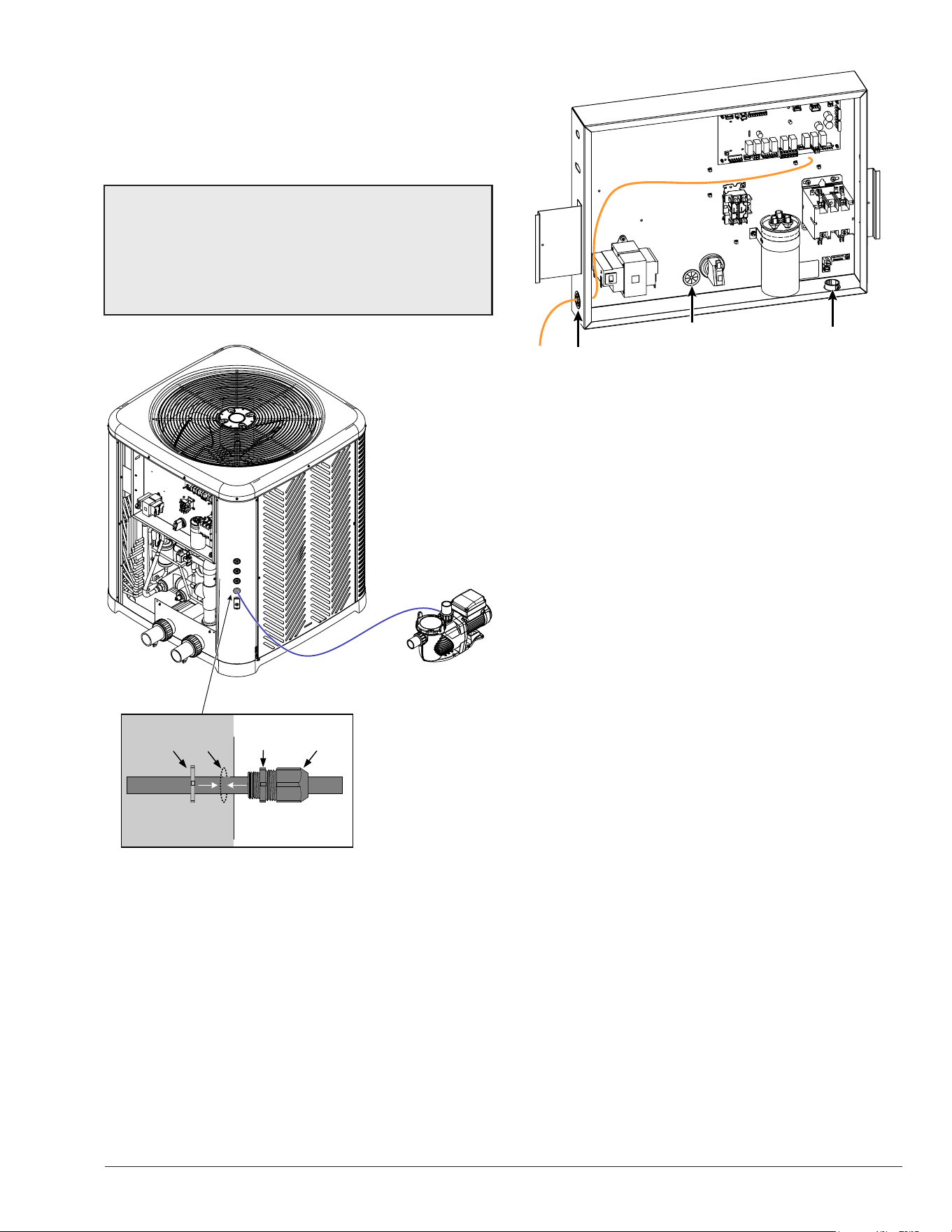
75
6. In the case you decide to remove the grommets to
connect external devices to the heater, run wires using
metallic conduit or outdoor-resistant cables. Then,
connect the conduit or cables to the knockout using
liquid tight connectors to prevent water or dust from
entering the system. See Figure 134.
NOTE: Please refer to Article 680 of the National Electrical
Code for general requirements related to swimming
pools and equipment, and to Article 440 for special
considerations that are necessary for circuits supplying
hermetic refrigeration motor/compressors. Additionally,
make sure to refer to the electric specications and
standards provided by your local authorities.
Metallic
ring
Panel
hole
Sealing
ring
Sealing
nut
Inside cabinet
Metallic
ring
Panel
hole
Sealing
ring
Sealing
nut
Outside cabinet
Figure 134. Wiring External Devices Using Liquid Tight
Connectors
7. Use the grommets in the control box to run wires from
inside the corner post to the inside of the box, up to
the control board terminal(s). See Figure 135.
a. Use the grommets located next to the transformer
and pressure switch for low-voltage signals
and low-voltage external power sources.
b. Use the grommet located under the main contactor
for any additional high-power signals or high-voltage
external power sources.
Figure 135. Grommets in Control Box
8. Connect the external wires to the appropriate
terminal(s) on the control board. Refer to the following
sections for details about wiring each terminal using
the supplied harness accessories and field-supplied
parts.
Valve Control Actuators Wiring
The control is designed to operate standard 24VAC 2-way
and 3-way valve actuators. By default, valve outputs 1
and 2 are congured to be controlled from the Raymote
app via Wi-Fi. In this mode, the heater must be connected
to a local Wi-Fi network to manually command the valves
or use online automation routines.
Alternatively, the valve control can be set to operate
automatically by the heater controller using the “Pool-
Spa” mode. Please refer to section 13 (Installer menu) on
page 21 for details about valve control modes.
In “Pool-Spa” mode, the control will set the valves to
the requested state when there is an active thermostat
demand for pool or spa mode. If the control also operates
the pump, it will shut off for 30-seconds before the valves
change state to avoid pump head pressure during the
transition. The display will show “Valve Chng Delay”
during this time. The valve outputs will not change until
there is a change in operation mode (any pool or spa
mode).
1. Follow the general instructions for wiring external
devices to connect the valve actuator(s) harness
from the valves to the control board of the heater.
See Figure 136.
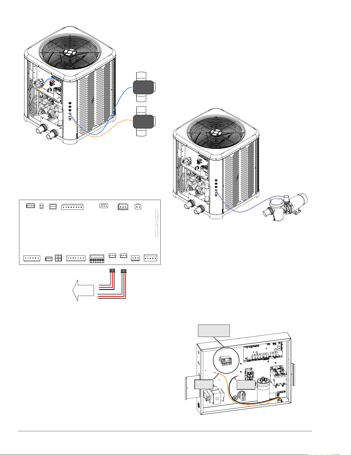
76
3-way valve
Actuator
3-way valve
Actuator
Figure 136. Wiring Valve Actuators
2. Connect the field-supplied valve actuator harnesses
to the terminals of the control board marked as
"VALVE 1" [P19] and "VALVE 2" [P20]. Note that the
rating of the control contacts is 0.75A at 24VAC. See
Figure 137.
3A
3A
COMM
(RS-485)
P12
P13
P10
P6
P16
P7
REMOTE
SELECTOR
P1
F1
F2
VARIABLE
SPEED PUMP
P8
SINGLE
SPEED
PUMP
P5
P19P20
VALVE2
OUTPUT
VALVE1
OUTPUT
AUX 1 & 2
OUTPUTS
P4
P3
P11
P9
P2
FAN RVS COMP
SOLAR HEAT
& AUX INPUT
WPS LPS HPS
to valve
actuator
Figure 137. Wiring Valve Actuator Harnesses
Single-Speed Pump Control Wiring
The control is designed to operate a single-speed pump
with an output of 24VAC at a maximum of 0.75A. To
switch power and energize the pump, a eld-supplied
24VAC relay is required with common and normally-open
terminal(s) rated per pump specications.
By default, the single-speed pump output is set to be
controlled from the Raymote app using Wi-Fi. In this
mode, the heater must be connected to a local Wi-Fi
network to manually command the pump or utilize online
automation routines. Additionally, the single-speed pump
output can be controlled by the built-in local schedule
with up to four periods of operation per day or by the built-
in automatic mode "Heater Demand," which commands
the pump whenever the heater requires heat (or cool).
For more details about the single-speed pump control
modes, please refer to section 13 of the Installer menu
on page 21.
1. Check the power requirements of your single-speed
pump to determine the necessary power source.
Most pumps run at either 120V or 240V.
2. Follow the general instructions for wiring external
devices to run the pump power cables and power
source wires from the pump and power distribution
box to the control box of the heater.
Figure 138. Wiring Simple Speed Pump
3. Install a field-supplied relay inside the control
box. See Figure 139. The relay shall have a
coil for 24VAC, and contact terminals rated to
the current specifications of the pump. The next
components are recommended for this application
a. For devices that require less than 10 amps, use
an OMRON LY2F AC24 (Raypak Kit # 008784F) or
similar relay.
b. For devices that require 10 amps or more, use an
OMRON G7L-2A-BUBJ-CB AC24 or similar relay.
From power
distribution
From power
distribution
From power
distribution
To the
Pump
From power
distribution
Install a 24VAC relay
to drive power to
the single-speed pump
Figure 139. Install Relay in Control Box
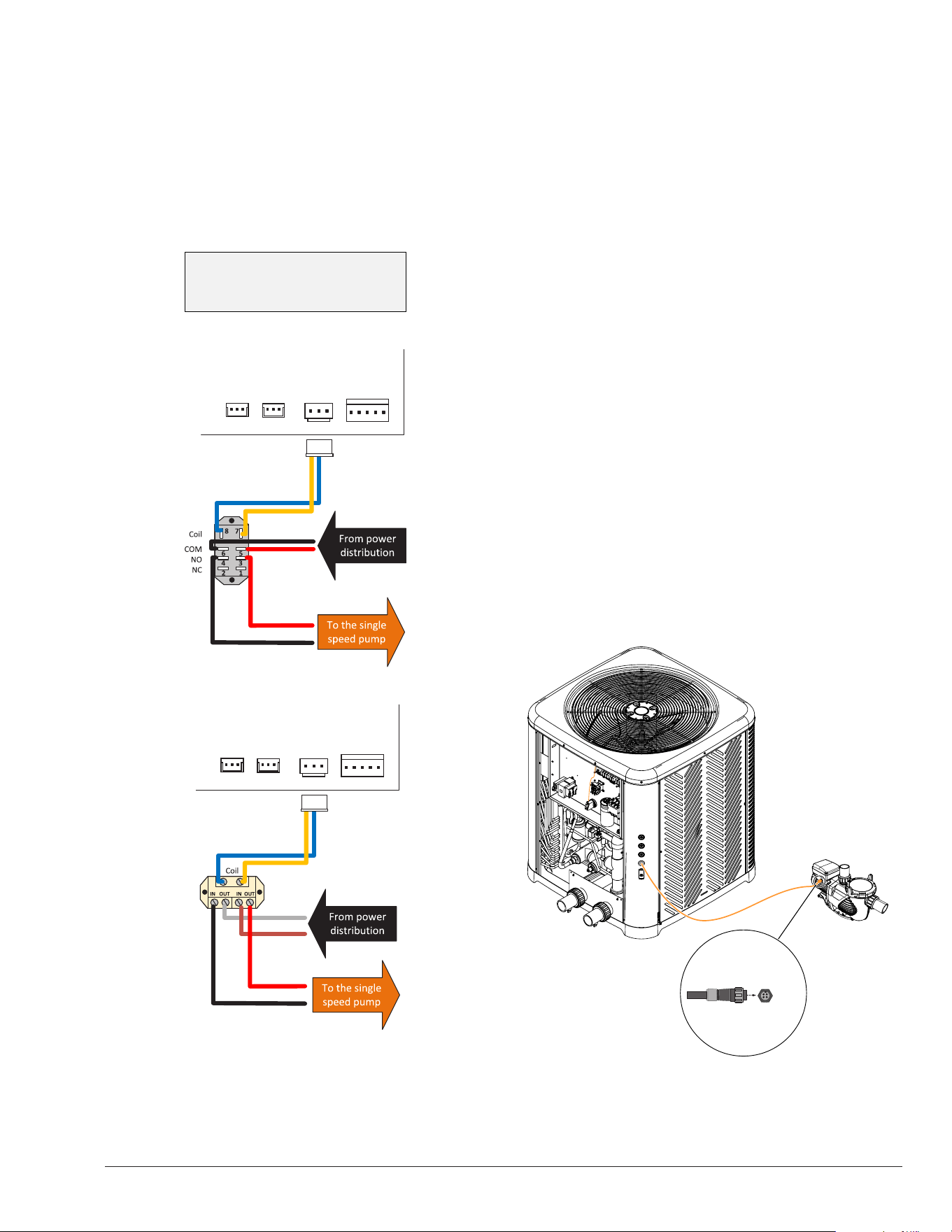
77
4. Use the harness adapter supplied in the accessory
bag labeled as “single-speed pump” to connect the
field-supplied relay to the terminal of the control
board marked as “PUMP” [P5]. Connect the other
end of the harness to the coil terminals of the relay,
as shown in Figure 140.
5. Connect the wires coming from the pump and the
power distribution box to the relay contact terminals,
as shown in Figure 140.
IMPORTANT:
Ensure that the relay works with 24V AC. Check
the relay terminal configuration, as it may differ
from the examples in the illustration.
P8
SINGLE
SPEED
PUMP
P5
P19P20
P8
SINGLE
SPEED
PUMP
P5
P19P20
Figure 140. 24VAC Relay Wiring
6. By following this configuration, the control board can
operate the field-supplied relay, which in turn supplies
power to the single-speed pump and allows it to turn
on or off.
Smart Variable-Speed Pump Control Wiring
The Crosswind V control is designed to operate Aquastar
Smart and Raypak Protégé variable-speed pumps. It
comes equipped with a dedicated communication port
labeled "COM" [P12]. To connect a Protégé variable-
speed pump to the Crosswind V, use the RS-485
Modbus harness (P/N: 652281). To connect an Aquastar
Smart variable speed pump, use the harness included
with the pump along with the Raypak "RS-485 Harness
adapter" kit (P/N: 100-10004059). Ensure to change the
Aquastar RS-485 address setting to number "2".
By default, the variable-speed pump control is disabled.
However, when the option is enabled and set to operate
a "Protégé VSP", the default control mode is to command
the pump using the Raymote app via Wi-Fi. To use this
mode, the heater must be connected to a local Wi-Fi
network to manually command the pump or use online
automation routines. Additionally, the variable-speed
pump can be controlled by the built-in local schedule
with up to 4 periods of operation per day or by the built-
in automatic mode "Heater demand" that commands
the pump whenever the heater needs heat or cool. For
details on the single-speed pump control modes, refer to
section 13 in the Installer menu on page 21.
1. Follow the general instructions for wiring external
devices to run the RS-485 harness from the Smart
variable-speed pump to the control box of the heater.
2. Connect the keyed circular connector of the pump
harness to the pump. See Figure 141.
Pump
side
Figure 141. Keyed Circular Connector
3. Then connect the other end of the RS-485 Modbus
harness to the terminal labeled as “COM” [P12] on
the control board. See Figure 142.
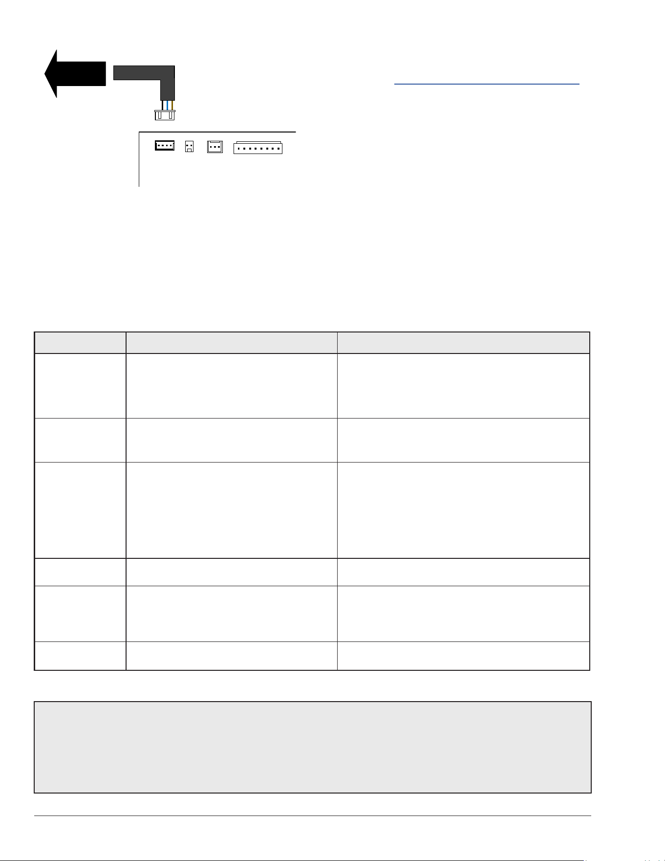
78
COMM
(RS-485)
P12
P13
P10
P6
To Smart
VS pump
Figure 142. Wiring 24VAC Relays
4. With this setup, the control board can control a
Raypak Protégé and Aquastar Smart variable-speed
pump. Make sure to enable and configure this option
from the Installer menu of the heater.
5. If the heater displays “Pump Ctrl Fail,” ensure that the
Modbus harness is connected on both ends, and the
pump settings for the RS-485 Pump address are “2”
Brand Models Note
Aquastar PLP150S, PLP300S • Compatible with Crosswind V P12 "COM" port.
• To be used with the Raypak "RS-485 Harness
Adapter" kit (P/N 100-10004059).
• Set pump setting "Pump Address" to "2".
Hayward Maxflo VS™, Super Pump® VS, TriStar® VS,
THP VS Pump family, HCP3000 series VSP,
others*
• Compatible with Crosswind V 30VDC digital outputs
and Auxiliary relay outputs.
• The pumps may require to setup a DIP switch selector.
Pentair IntelliPro®, IntelliFlo®, SuperFlo®,
SuperMax®, WhisperFlo®, Max-E-Pro®,
others*
• Compatible with Crosswind V 30VDC digital outputs
and Auxiliary relay outputs.
• The pumps may require enabling the digital selector
from the pump configuration menus.
• These pumps may require an IntelliComm® control
center, IntelliComm® II Interface adapter, the “relay
control board” or “digital input wiring kit”.
Waterway Power Defender 165 / 225 / 270, others* • Compatible with Crosswind V 30VDC digital outputs
and Auxiliary relay outputs.
Jandy VS PlusHP, VS FloPro, others* • These pumps don’t have direct compatibility with
Crosswind V 30VDC digital outputs
• Crosswind V Auxiliary relay outputs can be used to
control these pumps.
Speck Pumps BADU EcoM3 V • Compatible with Crosswind V 30VDC digital outputs
and Auxiliary relay outputs.
Table G. Compatible Pump Models and Brands
and the Baud rate is set to 9600. For more information
on the Protégé variable-speed pump settings, please
refer to the Protégé Variable-Speed Pump manual.
Digital Control Variable-Speed Pump Wiring
The control is designed to operate multiple brands and
models of variable-speed pumps that are compatible with
digital control speed selection. It features a dedicated 5-pin
terminal labeled as “VAR PUMP” [P8], which provides up
to 4 digital outputs of 30VDC that are compatible with
the external control port of most common variable-speed
pump brands in the pool industry.
Table G below provides a list of some of the brands
and pump models that can be compatible with the
30VDC digital output-input control for speed selection.
It's important to note that some models may require an
adapter, add-on, or wiring kit to work with this control
output, while other variable-speed pump controllers have
the digital input terminals built-in and ready to connect.
*NOTE: Before connecting the digital control outputs of the heater to a variable-speed pump, carefully review the
installation and operation manual to conrm compatibility and determine if any additional components or congurations
are necessary for the pump controller. This information can be found in sections titled:
• External control via digital inputs
• Using external input signal
• Digital input wiring
• Connecting to an automation system
• External relay speed control wiring
• Control system relay contacts
• Drive low voltage connections
• Remote selection of pump speed
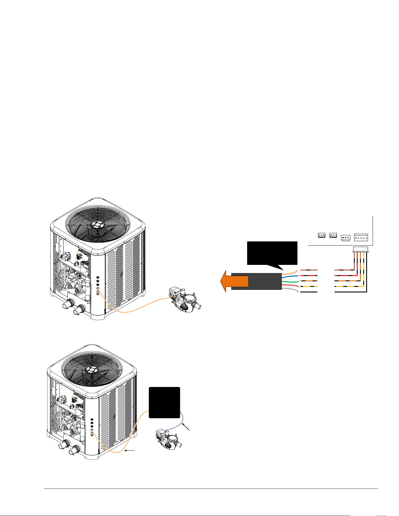
79
By default, the variable-speed pump control is disabled.
However, when the variable-speed pump option is
enabled and set to operate in the "4-speed control" mode,
the default control mode is set to command the pump
with the Raymote app via Wi-Fi. In this mode, the heater
must be connected to a local Wi-Fi network to manually
command the pump or use online automation routines.
Furthermore, the variable-speed pump can be controlled
by the built-in local schedule with up to four periods of
operation per day, or by the built-in automatic mode
"Heater demand," which commands the pump whenever
the heater requires heat or cool. For more information
on the single-speed pump control modes, please refer to
section 13 of the Installer menu, located on page 21.
1. Follow the general instructions for wiring external
devices and run a 5-conductor cable from the pump
controller or digital interface, to the control box of
the heater. The specific pump controller to be used
is determined by the manufacturer and model of the
pump. Refer to the installer manual of your variable-
speed pump for more details.
Figure 143. Cable Routing to the VS Pump Controller
5-conductor
cable
Proprietary
RS-485 Pump
harness
Variable
Speed
Pump Digital
to RS-485
interface
Figure 144. Cable Routing to a VS Pump Digital Interface
2. Inside the heater's control box, use the harness
adapter labeled "Pump speed selector" that comes
with the accessories bag to connect the 5-conductor
cable to the control board terminal labeled "VAR
PUMP" [P8]. The adapter can supply 4 digital outputs
at 30VDC and a ground signal. Make sure to identify
the wires in both ends of the 5-conductor cable. Refer
to Figure 145 for guidance.
3. Connect the other end of the 5-conductor cable to
the digital input terminals on the variable-speed
pump controller or the digital to RS-485 pump
control interface. Figure 146 through Figure 150,
provide examples of connections for certain variable-
speed pump brands and models. Please refer to
the installation and configuration manual of your
variable-speed pump for more details on connecting
and configuring the digital input speed selector.
4. Once the wiring is complete, make sure to
configure the variable-speed pump controller or
interface adapter according to the manufacturer's
specifications. Follow the instructions provided by
the pump manufacturer to ensure compatibility and
correct operation of the pump.
VARIABLE
SPEED PUMP
P8
SINGLE
SPEED
PUMP
P5
P19P20
VALVE2
OUTPUT
VALVE1
OUTPUT
Speed 1
Speed 2
Speed 3
Speed 4
Ground
To VS pump
controller
Identify the wires of the 5
conductor cable in both
end of the cable. The
colors may differ.
Figure 145. 5-Conductor Cable Wiring
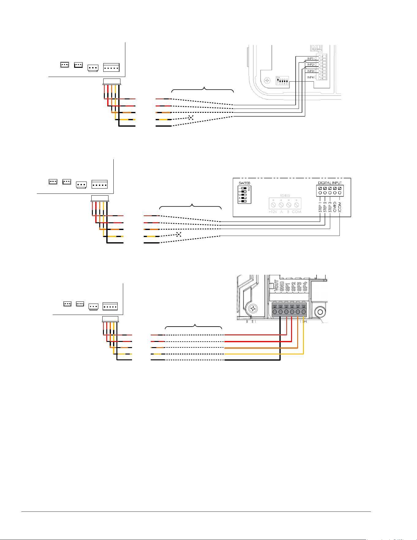
80
VARIABLE
SPEED PUMP
P8
SINGLE
SPEED
PUMP
P5
P19P20
VALVE2
OUTPUT
VALVE1
OUTPUT
Speed 1
Speed 2
Speed 3
Speed 4
Ground
5-conductor cable
between heater and
pump controller
Crosswind V control board Hayward VS Pump controller
Figure 146. Hayward THP VS Pump Family
VARIABLE
SPEED PUMP
P8
SINGLE
SPEED
PUMP
P5
P19P20
VALVE2
OUTPUT
VALVE1
OUTPUT
Speed 1
Speed 2
Speed 3
Speed 4
Ground
5-conductor cable
between heater and
pump controller
Crosswind V control board Hayward VS Pump controller
Figure 147. Hayward MaxFlo VS, Super Pump VS and TriStar VS
VARIABLE
SPEED PUMP
P8
SINGLE
SPEED
PUMP
P5
P19P20
VALVE2
OUTPUT
VALVE1
OUTPUT
Speed 1
Speed 2
Speed 3
Speed 4
Ground
5-conductor cable
between heater and
pump controller
Pentair VS pump with Relay Control Board
Crosswind V control board
Figure 148. Pentair IntelliFlow and IntelliPro equipped with Relay Control Board
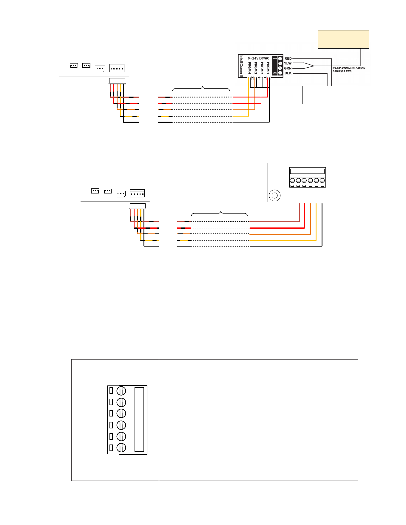
81
Auxiliary Outputs 1 and 2 Wiring
The control is equipped to operate two general-purpose
dry-contact relay outputs. The control provides a terminal
block with screw connections labeled "AUX 1" and
"AUX 2". See Figure 151. Each auxiliary output can
independently control one or multiple external devices or
electric ON/OFF circuits. These auxiliary relay terminals
do not supply voltage and act as power interrupters.
Before using these auxiliary outputs, take into account
the following considerations:
• Use the auxiliary output to drive power from an external
power source to an external device or electric circuit.
• The auxiliary outputs are rated for applications of up to
3 amps. For loads above 3 amps, install a larger relay
or contactor in cascade with the auxiliary output.
• Each auxiliary output works as a SPDT relay, providing
a Common terminal "C", a Normally Open terminal
"NO", and a Normally Closed terminal "NC". Select
the proper terminals based on the needs of your
application.
Pentair VS pump
Field-supplied 10V DC
power supply
VARIABLE
SPEED PUMP
P8
SINGLE
SPEED
PUMP
P5
P19P20
VALVE2
OUTPUT
VALVE1
OUTPUT
Speed 1
Speed 2
Speed 3
Speed 4
Ground
5-conductor cable
between heater and
pump controller
Crosswind V control board
Figure 149. Pentair VS Pumps with IntelliComm II Interface Adapter
GND
INP#4
INP#3
INP#2
INP#1
+12V
GND
INP#4
INP#3
INP#2
INP#1
+12V
VARIABLE
SPEED PUMP
P8
SINGLE
SPEED
PUMP
P5
P19P20
VALVE2
OUTPUT
VALVE1
OUTPUT
Speed 1
Speed 2
Speed 3
Speed 4
Ground
5-conductor cable
between heater and
pump controller
Waterway VS pump controllerCrosswind V control board
Figure 150. Waterway Power Defender VS Pumps with Discrete Switch Inputs
AUX1
AUX2
C2
NO2
NC2
C1
NO1
NC1
C2 – Common terminal of Auxiliary 2 output. Connect an external signal or
power line here.
NO2 – Normally Open of Auxiliary 2 output. This terminal yields the signal
connected in C1 but only after the Auxiliary 1 output is commanded.
NC2 – Normally Closed of Auxiliary 2 output. This terminal yields the signal
connected in C1. Output is interrupted when the Auxiliary 1 is commanded.
C1 – Common terminal of Auxiliary 1 output. Connect an external signal or
power line here.
NO1 – Normally Open of Auxiliary 1 output. This terminal yields the signal
connected in C1 but only after the Auxiliary 1 output is commanded.
NC1 – Normally Closed of Auxiliary 1 output. This terminal yields the signal
connected in C1. Output is interrupted when the Auxiliary 1 is commanded.
Figure 151. Auxiliary 1 and 2 Outputs
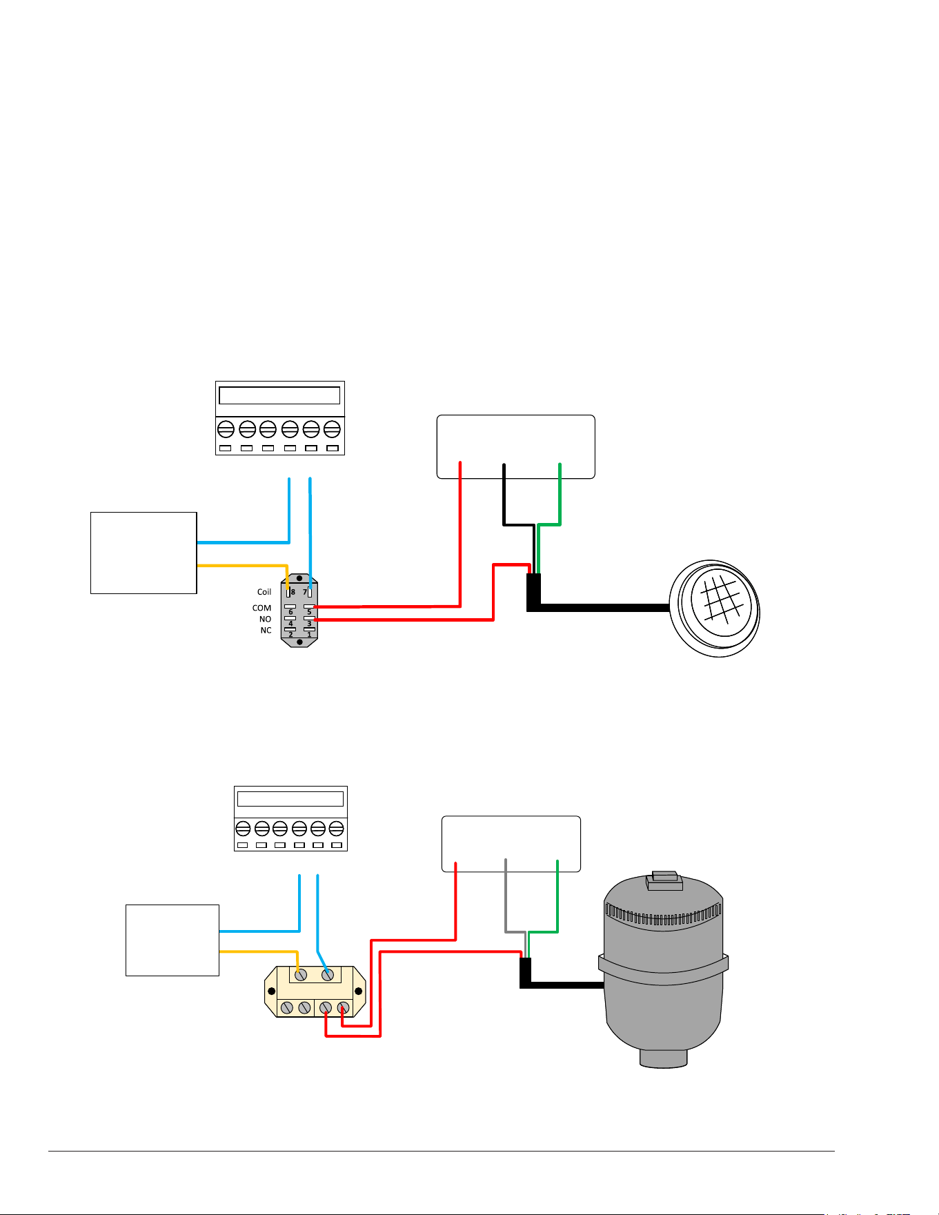
82
The default setting for Auxiliary Outputs 1 and 2 is to be
controlled through the Raymote app using Wi-Fi. To use
this mode, the heater must be connected to a local Wi-Fi
network in order to manually command the Auxiliaries or
run automation routines Online. Alternatively, the Auxiliary
outputs can be congured to be controlled by the built-
in local schedule, which allows for up to four periods
of operation per day, or by the built-in automatic mode
"Auxiliary Heat," which commands the auxiliary output
to operate an external heater. For more information on
the control modes for Auxiliary Outputs 1 and 2, refer to
section 13 of the Installer menu on page 21.
AUX1
AUX2
C2
NO2
NC2
C1
NO1
NC1
+12V C GND
Pool Lights
12V Transformer
Heat Pump
Auxiliary Outputs
Use a 24VAC field-supplied relay to
interrupt 1 or 2 lines of the external
device to control
This example assumes a
Pool light that works with
12V.
Similar wiring configuration
applies for other voltages.
Other voltages may require
a transformer or other
power supply.
24V AC
Transformer
Figure 152. Example 1: Pool Light Wiring
AUX1
AUX2
C2
NO2
NC2
C1
NO1
NC1
L1 N GND
Air Blower
Power source
Heat Pump
Auxiliary Outputs
Use a 24VAC field-supplied relay to
interrupt 1 or 2 lines of the external
device to control
This example is for a 120V
air blower
IN OUT IN OUTIN OUT IN OUT
24V AC
Transformer
Figure 153. Example 2: Air Blower Wiring
1. Determine the power requirements of the external
device that will be controlled or energized by the
auxiliary output(s).
2. Follow the general instructions for wiring external
devices to run the control signal or power line(s)
from the power source to the heater control box
and from the control box to the device being
controlled/energized. Refer to the next examples
of external control using the Auxiliary outputs:
- Controlling pool lights
- Controlling an air blower
- Controlling an external heater from the HPPH
Auxiliary output.
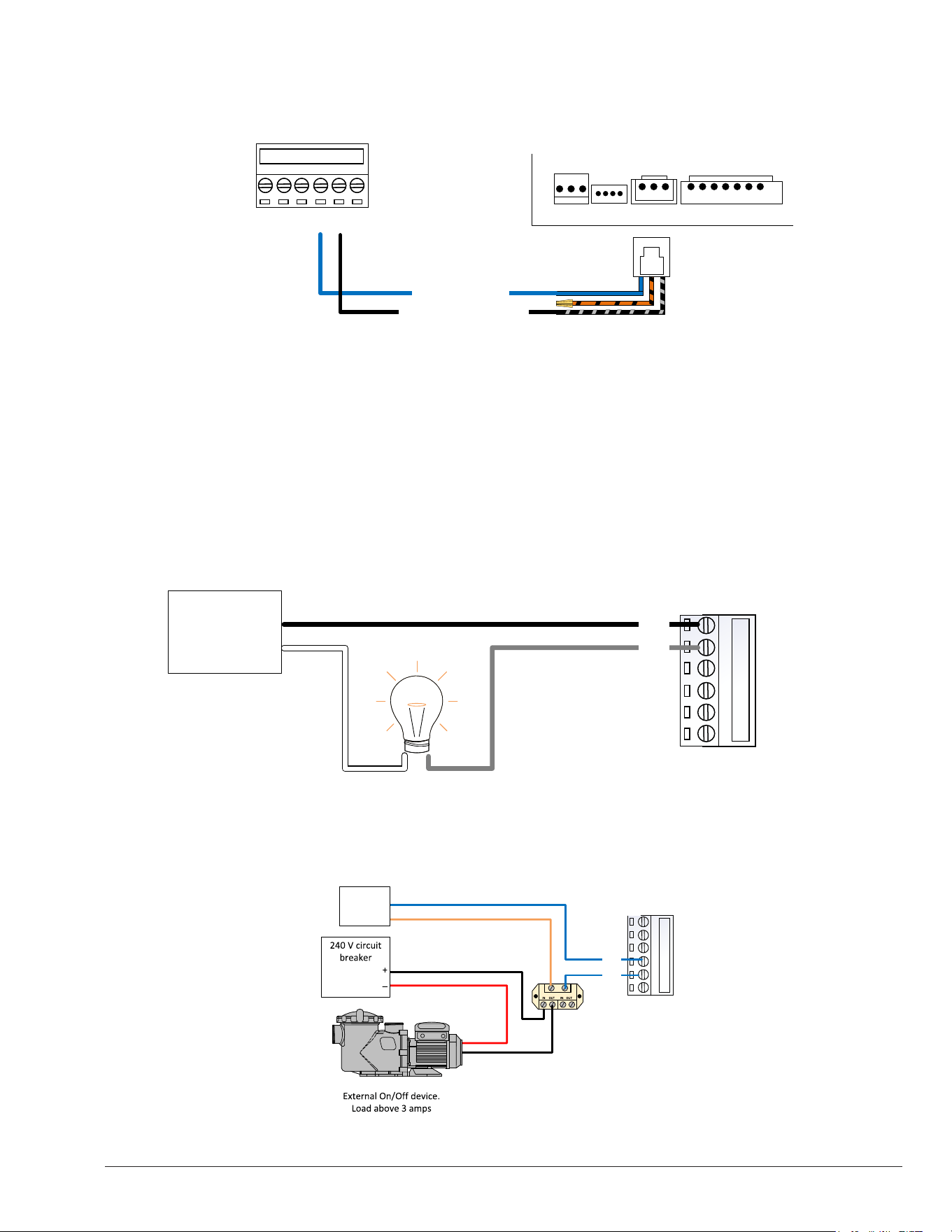
83
3. Connect the wires coming from the power
source and the external device, following these
guidelines. See Figure 155 for further clarification.
a. If the application requires less than 3 amps, the
terminal block on the Crosswind V control board can be
used to drive power to the external device.
b. For applications over 3-amps, use a field-supplied
relay rated to the amperage and voltage of your
application, connected in cascade to the Auxiliary
output of the heater. See Figure 156.
4. Ensure that you follow the wire gauge and wire length
requirements specified for the external device. Use
the appropriate power source for your application. If
you are using field-supplied relays, make certain that
the coil is rated for the voltage of the external power
source.
AUX1
AUX2
C2
NO2
NC2
C1
NO1
NC1
Heat Pump
Auxiliary Outputs
Remote
selector
harness
L
R
G
24V
SPA
POOL
WPS HL1 HL2 VNT
P6 P7 P8 P4A
AVIA Gas Heater
Remote selector – Pool
mode
<< 24 VAC signal <<
>> Pool mode selection >>
Use INSTALLER menu to
configure Auxiliary Output
mode as “Auxiliary Heat”
Configure the heater to
operate in Remote mode.
Figure 154. Example 3: Gas Heater Commanded as Auxiliary Heater
AUX1
AUX2
C2
NO2
NC2
C1
NO1
NC1
24V AC
Transformer
Use a 24VAC field-supplied
relay to interrupt 1 or 2 lines of
the external device to control
Figure 156. External Device Wiring to Auxiliary Output
AUX1
AUX2
C2
NO2
NC2
C1
NO1
NC1
+
_
Crosswind V auxiliary outputs
can be used directly.
External On/Off device. Load
under 3 amps. at 24VAC
Power Supply
Figure 155. Applications up to 24V AC, 3 Amps max.
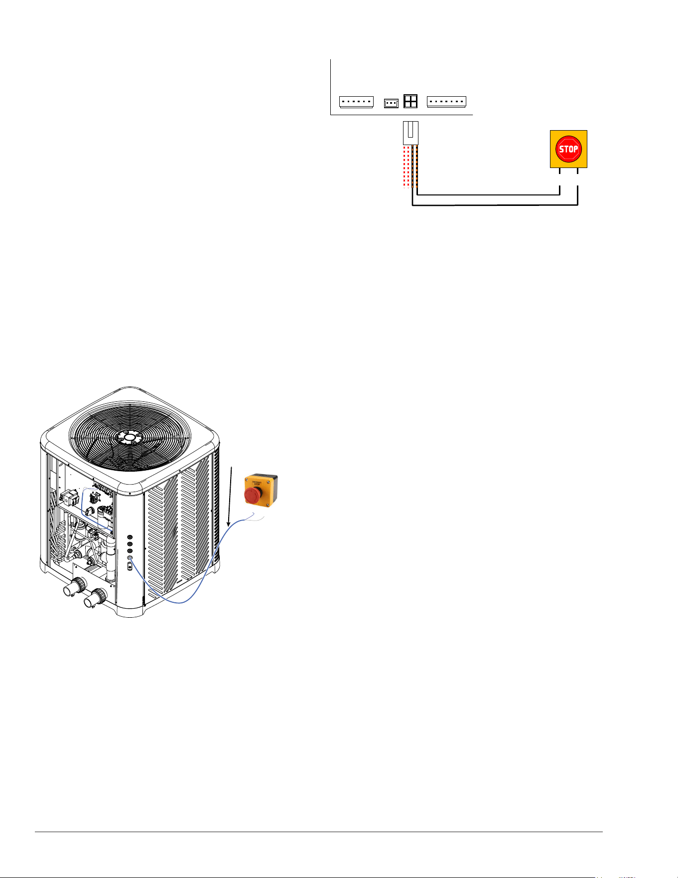
84
Auxiliary Input Wiring
The control is designed to monitor an external signal
using the "Auxiliary Input." This input has 24VAC on one
terminal and uses the other terminal to receive back the
24VAC to close the auxiliary input circuit. An external
"normally closed" safety contactor, such as an emergency
stop or an external "disable" signal from an automation
controller, can use this auxiliary input. See Figure 157.
By default, the Auxiliary Input is disabled at the factory.
You can enable this input to either cause the heater to
report the warning fault "Aux Input Warning" on the LCD
or to disable the operation of the heater and report the
interlock fault "Aux Input Fault." Refer to section 13,
Installer menu on page 23 for more information about
the Auxiliary Input.
The following steps and wiring diagrams demonstrate
the use of the Auxiliary Input with an "Emergency Stop"
button that disables the operation of the heater when the
Auxiliary Input is congured as "Interlock".
1. Follow the general instructions for wiring external
devices by connecting two wires from the "Emergency
Stop" button to the heater's control box.
C NC
Use a 2-wire cable to
send the 24VAC signal
from the heater's
Auxiliary Input to the
"C" terminal of the Stop
button. Use the "NC"
terminal of the Stop
button to return the
signal to the heater's
Auxiliary Input.
Figure 157. Cable Routing to the VS Pump Controller
2. Inside the heater's control box, connect the 2-wire
cable to the control board terminal labeled "SOLAR"
[P11] using the harness adapter labeled "Solar
Temperature Sensor / Auxiliary Safety Input" supplied
with the heater in the accessories bag. Make sure to
use only the orange wire with black stripes to connect
the external safety device. See Figure 158 for details.
P3
P11
P9
P2
FAN RVS COMP
SOLAR HEAT
& AUX INPUT
WPS LPS HPS
C NC
Figure 158. Auxiliary Input Wiring
3. Make sure to enable and configure the Auxiliary
Input from the INSTALLERS Menu. For detailed
information about the Auxiliary Input, refer to section
13, "Auxiliary Input" on page 23.
Solar Heater Integration
The control is equipped to function as a solar heater
controller integrated with the operation of the heat pump
pool heater. It provides a 10K sensor input in P11 and
a 3-way valve output in P9 of the control board labeled
"SOLAR 3-WAY VALVE." When the "Solar Heating"
function is enabled from the Installer Menu, Terminal
P9 supplies 24VAC at 0.75 amps to drive a 3-way valve
actuator. Terminal P11 provides an input to connect a 10K
thermistor to be used as a 'Solar sensor.' Please note that
the 10K solar sensor is not included with the heater. You
can order a 'Temp Sensor 10K' spare sensor (service P/N
100-10001050 - KIT - HPPH Sensor Solar 10K) to use as
the Solar sensor.
By default, the "Solar Heating" function is disabled
at the factory. You can enable this function from
the Installer Menu and congure it to operate a
Solar Heating collector simultaneously with the
Crosswind V Heat Pump Pool Heater. For detailed
information about conguring the Solar Heating
function, refer to "Solar Heating Integration
(Heat/Cool Models Only)" on page 22.
The following steps and wiring diagrams describe the
expected installation of the Solar heater components in
the pool piping.
1. The 10K "Solar sensor" should be installed before
the solar 3-way valve. The ideal position is between
the pump and the lter.
2. Install a "Solar 3-way valve" downstream of the lter
to divert water ow to either the Heat Pump or Solar
collector when commanded. The default ow position
should be directed towards the Heat Pump.
3. Install a "check valve" at the outlet of the solar heater
to prevent backow to the solar collector. See Figure
159.
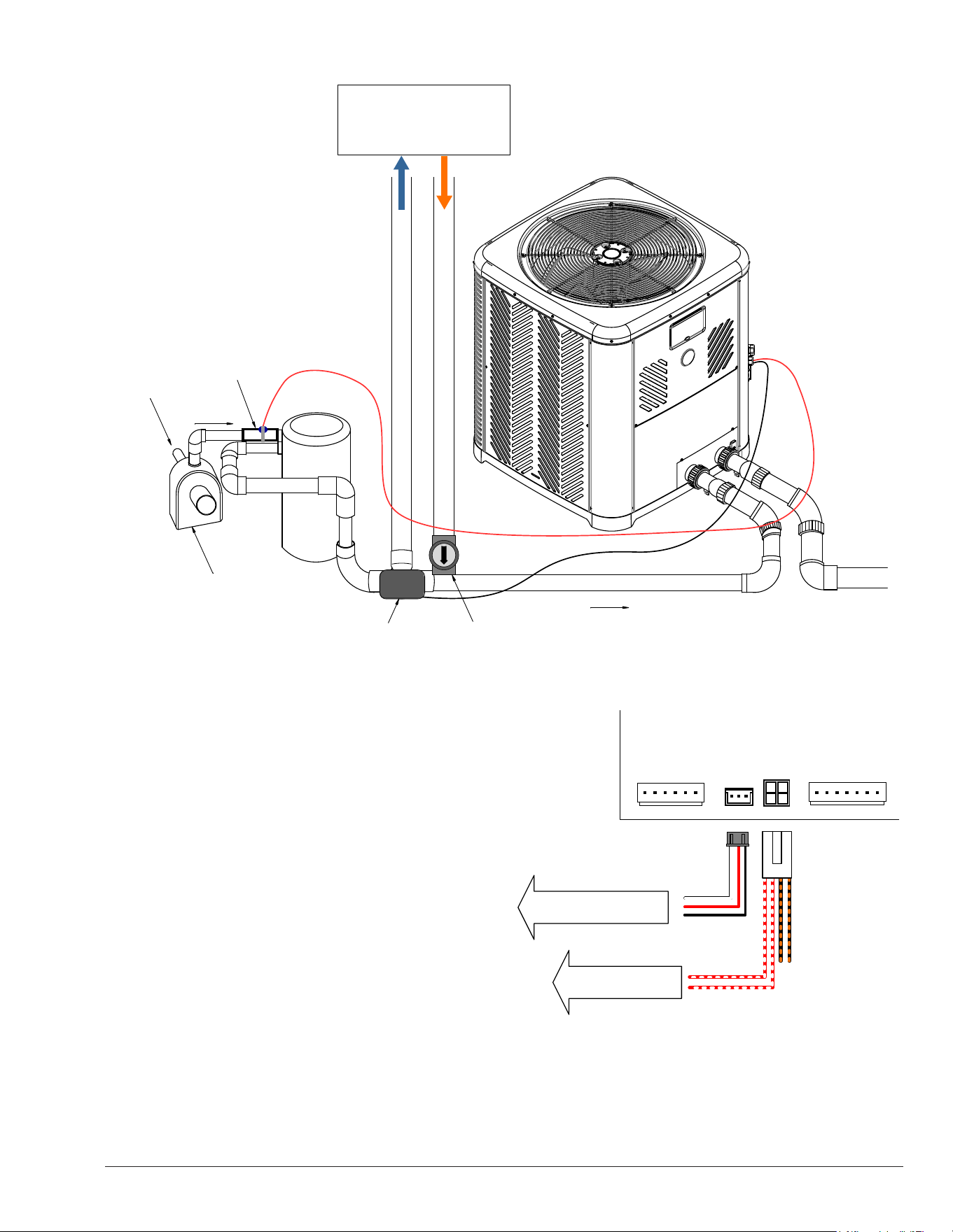
85
FILTER
WATER IN
(TO POOL
OR SPA)
PUMP
POOL-SOLAR 10K
SENSOR
SOLAR COLLECTOR
INLET OUTLET
SOLAR 3-WAY
VALVE ACTUATOR
CHECK
VALVE
FLOW
INLET
OUTLET
Figure 159. Solar Heater Components in the Piping
4. Follow the general instructions for wiring external
devices and route the wires for the "Solar sensor" and
"Solar 3-way valve" to the control box of the heater.
5. Inside the control box of the heater, connect the
wires for the "Solar sensor" to the control board
terminal labeled as "SOLAR" [P11] using the harness
adapter labeled as "Solar Temperature Sensor /
Auxiliary Safety Input" provided in the accessories
bag. Connect the Red with White wires for a 10K
temperature sensor and use the terminal [P9] to
connect a standard 3-way valve actuator for the
"Solar 3-way valve". Refer to Figure 160 for details.
6. Enable the "Solar Heating" option and congure
the necessary parameters based on your system
requirements and operation preferences from the
Installer menu. Refer to section 13 in page 21 for
further details on conguring the Solar Heating
function.
P3
P11
P9
P2
FAN RVS COMP
SOLAR HEAT
& AUX INPUT
WPS LPS HPS
Solar 3-way valve
actuator
Solar Sensor (10K)
Figure 160. Solar Heat & Auxiliary Input
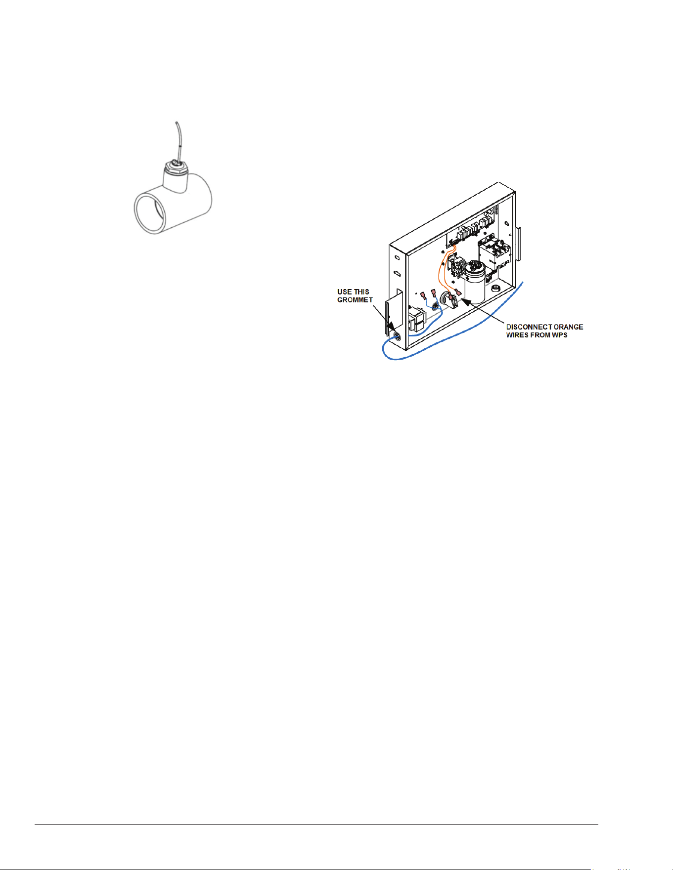
86
Water Flow Switch (WFS) Wiring
The WFS kit (P/N: H000166) comes with a limited wire
length. Extend the wires as required, ensuring they do
not exceed 20 ft. in length.
Figure 161. Water Flow Switch
• Before starting any work on the heater, make sure to
shut off all power to avoid the risk of electrical shock
or damage to components.
• Ensure to run the WFS wires separately from the
high-voltage wires. Low-voltage wiring should not be
run together with high-voltage lines.
Follow the next set of instructions to connect the WFS to
the heater.
1. After installing the WFS onto the heater's inlet
pipeline, route the wires from the WFS to the heater's
corner post. See Figure 68.
2. Use the grommet/knockouts located on the heater's
corner post to route WFS wires into the heater. Ensure
that liquid-tight connectors are used to prevent water
or dust intrusion. See Figure 68.
3. To access the heater's front control cover panel, use
a 1/4" hex head screwdriver to unscrew the six (6)
screws. See Figure 130.
4. To remove the front panel, pull the bottom of the
panel downward and outward, and then disconnect
the wire attached to the rear of the user interface.
See Figure 131.
5. The panel should now be free for removal. See
Figure 131.
6. Set the control panel cover aside to reinstall when
wiring is completed.
7. Use the grommets in the control box to run wires from
inside the corner post to the inside of the electrical
junction box, using the grommets located next to the
transformer. See Figure 162.
8. Locate the orange wires connected to the Water
Pressure Switch (WPS). Proceed to disconnect the
terminals from the WPS. See Figure 162.
9. Connect the 2-wires from the WFS with the 2 orange
wires that were disconnected from the WPS.
a. For a clean installation, use ¼” male spade
terminals (.032 x .250, 18-22 AWG) for each wire
of the WFS to mate with the WPS orange female
terminal wires.
b. Alternatively, connect the WPS orange wires with
the WFS wires using wire nuts or butt splices.
10. Reinstall the control panel. Ensure to reconnect the
display board before fastening the front panel.
WFS
WIRING
Figure 162. WFS Wire Routing into J-Box

87
28. REPLACEMENT PARTS
NOTE: To supply you with the correct part, it is
important that you supply the heater model and serial
number.
Any part returned for replacement under standard company
warranties must be properly tagged with a return parts tag,
completely lled in with the heater serial number, model
number, etc., and shipped to the Company freight prepaid.
If determined defective by the Company and within
warranty, a like part or equal substitution will be returned,
freight collect. Credit will not be issued.
MANUFACTURER:
Av. New York 207, Parque Industrial Oradel, C.P.
88285 Nuevo Laredo Tamps. Mexico
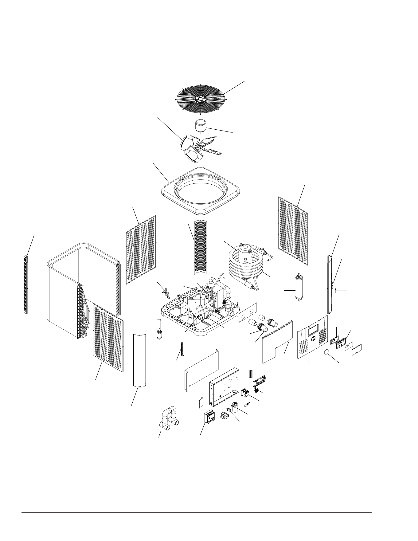
88
7-S
1-F
2-F
6-S
2-S
2-S
5-S
9-S
3-S
2-S
4-S
8-S
5-M
3-H / 4-H
1-H
7-H
5-H
2-H
1-S
2-M
1-M
1-C
6-C
5-C
8-C
7-C
10-S
3-S
6-J
1-J
4-J
5-J
3-J
2-J
8-J**
3-C
2-C
10-M
7-M
8-M
9-M
MODELS 4550-8550
29. ILLUSTRATED PARTS LIST
89
CALL OUT DESCRIPTION 4550 5550 6550 8550
C CONTROLS
1-C TX Valve 100-10000385 100-10000386 100-10000386 100-10000387
2-C Low Pressure Switch 100-10000633 100-10000633 100-10000633 100-10000633
3-C High Pressure Switch 100-10000634 100-10000634 100-10000634 100-10000634
5-C Inlet Temp Sensor 100K 100-10000635 100-10000635 100-10000635 100-10000635
6-C Outlet Temp Sensor 10K 100-10000636 100-10000636 100-10000636 100-10000636
7-C Ambient Temp Sensor 100-10000637 100-10000637 100-10000637 100-10000637
8-C Coil Defrost Sensor 100-10000643 100-10000643 100-10000643 100-10000643
9-C Harness Assy J-Box 100-10000394 100-10000394 100-10000394 100-10000394
10-C Harness Assy/Fan 100-10000396 100-10000396 100-10000396 100-10000396
11-C Harness Assy Contactor 100-10000397 100-10000397 100-10000397 100-10000397
12-C Harness Assy Rev Valve/Press Switches 100-10000398 100-10000398 100-10000398 100-10000398
13-C Harness Assy-Temp Sensor 100-10000399 100-10000399 100-10000399 100-10000399
14-C Harness Reversing Valve Connector* 100-10000644 100-10000644 100-10000644 100-10000644
15-C Variable-Speed Pump Harness 100-10000690 100-10000690 100-10000690 100-10000690
16-C Single-Speed Pump Harness 100-10000689 100-10000689 100-10000689 100-10000689
17-C Solar Sensor and Aux Safety Harness 100-10000688 100-10000688 100-10000688 100-10000688
18-C 3-wire Remote Harness adapter 100-10001036 100-10001036 100-10001036 100-10001036
19-C Kit - HPPH Sensor Solar 10K 100-10001050 100-10001050 100-10001050 100-10001050
H HEAT TRANSFER
1-H Heat Exchanger H000278 H000368 H000368 H000369
2-H PVC Union H000317 H000317 H000317 H000317
3-H Liquid Line Drier H000188 H000011 H000011 H000011
4-H Liquid Line Drier (EHC models) * NA NA H000004 H000004
5-H Compressor R-410A 208/230V 1PH 60Hz 100-10000400 H000348 H000012 H000014
6-H Compressor Power Plug (Not Shown) H000271 H000271 H000271 H000271
7-H Charge Compensator NA NA NA H000255
8-H Reversing Valve * (Not Shown) NA NA H000136 H000136
F FAN
1-F Fan Motor 100-10000638 100-10000638 100-10000638 100-10000638
2-F Fan Blade 100-10000639 100-10000639 100-10000639 100-10000639
J CONTROL BOX
1-J Fan Relay H000299 H000299 H000299 H000299
2-J Transformer 100-10000640 100-10000640 100-10000640 100-10000640
3-J Water Pressure Switch H000025 H000025 H000025 H000025
4-J Contactor H000043 H000043 H000043 H000043
5-J Capacitor H000051 H000051 H000051 H000051
6-J Control Board Digital 100-10000389 100-10000389 100-10000389 100-10000389
7-J Fuse (Not Shown) H000370 H000370 H000370 H000370
8-J Monitor** H000291 H000291 H000291 H000291
M MISCELLANEOUS
1-M PC Board Display 100-10000390 100-10000390 100-10000390 100-10000390
2-M Bezel Gasket 100-10000391 100-10000391 100-10000391 100-10000391
3-M UI Harness (Not shown) 100-10000393 100-10000393 100-10000393 100-10000393
4-M Touch-up Paint (Not Shown) 100-10000401 100-10000401 100-10000401 100-10000401
5-M Water Bypass 100-10000816 100-10000816 100-10000816 100-10000816
6-M Water Flow Switch (Not Shown) H000166 H000166 H000166 H000166
7-M HPPH Rheem Badge 100-10004473 100-10004473 100-10004473 100-10004473
8-M HPPH Raypak Badge 100-10004474 100-10004474 100-10004474 100-10004474
9-M HPPH Ruud Badge 100-10004475 100-10004475 100-10004475 100-10004475
10-M Plug Drain 1/4 NPT 100-10004354 100-10004354 100-10004354 100-10004354
11-M Accessories Bag (Not Shown) 100-10004854 100-10004854 100-10004854 100-10004854
12-M 24VAC/25A Relay (Not Shown) 100-10001060 100-10001060 100-10001060 100-10001060
13-M Flow Meter (Not Shown) 100-10001058 100-10001058 100-10001058 100-10001058
S SHEET METAL
1-S Access Panel 100-10000402 100-10000402 100-10000402 100-10000402
2-S Side Panel 100-10000403 100-10000403 100-10000403 100-10000403
3-S Corner Louver Panel 100-10000404 100-10000404 100-10000404 100-10000404
4-S Corner Solid Panel 100-10000405 100-10000405 100-10000405 100-10000405
5-S Corner Plug Holes Panel 100-10000406 100-10000406 100-10000406 100-10000406
6-S Jacket Top 100-10000407 100-10000407 100-10000407 100-10000407
7-S Grille Fan Guard 100-10000641 100-10000641 100-10000641 100-10000641
8-S Hurricane Bracket HT Pump SS H000357 H000357 H000357 H000357
9-S Sensor Cover H000362 H000362 H000362 H000362
10-S Front Cover Panel 100-10000388 100-10000388 100-10000388 100-10000388
*EHC models only.
**8-J Monitor is optional on voltage monitor models.
NOTE: Items 9-C through 19-C are not shown in the IPL illustration because they are part of the unit's wiring.

90
NOTES
Raypak, Inc., 2151 Eastman Avenue, Oxnard, CA 93030 (805) 278-5300