STEP 1:
MOUNTING THE HEATER
Mounting
CONDENSATION LINE
Condensate
STEP 4:
VENTING
Venting
STEP 2:
WATER CONNECTION
Water Quality
& Supply
STEP 5:
ELECTRICAL
Electrical
Wiring
STEP 3:
GAS CONNECTION
Gas Supply
START UP
Start Up
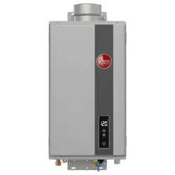
1. Install one screw for top hanging bracket in support
brace on the wall leaving a 1/4” gap between head of
screw and wall surface .
2. Align the EZ-Hang slot with the screw and lower into
place. Bracket can slide up and down for alignment.
A spacer is included if additional space is needed.
3. Secure the lower and upper bracket to the support
brace on the wall to fix in place.
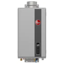
DIRECT VENT INSTALLATION
Compatible with Metal Fab, Rainbow, and
UBBINK standard concentric venting (3”/5”).
Condensate Drain trap must be connected to a drain.
A 1/2” ID tube must be run to suitable drain, looped to
form a trap, and filled with cup of water.
1. Connect cold and hot water at designated inlets.
2. Install service valves and a 150 psi rated pressure relief
valve at hot water outlet.
3. Water pressure of 65 psi (448 kPa) is required
to achieve maximum flow rate.
1. Ensure that all gas connections, regulator(s),
and meter are sized properly for the BTU/h rating. This
unit is 1/2” gas line compatible (see Gas Supply section
in the Use & Care Manual).
2. Install the gas shut-off valve directly on the gas supply
connection on the bottom of the water heater .
3. Connect the gas piping to the valve.
4. Check all connections and fittings for leaks.
1. This water heater plugs into a standard 120VAC,
3-prong grounded outlet for indoor installation.
2. Do NOT connect this water heater to a GCFI or
AFCI circuit.
Please see Use & Care Manual for more
details on mounting locations.
It is recommended that the exhaust pipe
have a 1/4” per foot downward slope
away from the unit when venting through
the wall as shown. Venting through a roof
requires a 1/4” per foot upward slope
toward the heater.
Use service valves for future service of the
water heater. Expansion Tank required for
installations using Recirculation.
A properly sized and installed gas supply is
critical to the proper operation of this water
heater. Please see National and Local Fuel Gas
Code for details.
CONCENTRIC VENT TERMINATION
VERTICAL VENT TERMINATION
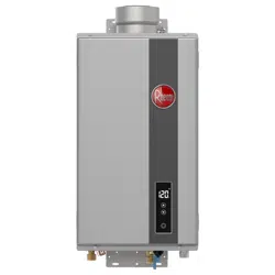
SETTING THE TEMPERATURE
Press the “▲” or “▼” button to adjust temperature between
100-120°F.
To adjust set point above 120°F, press the “▲” button
repeatedly until 120°F shows in the display.
Hold the “▲” button until the “120” on the display starts to
blink.
Press and hold the “▲” button for 5 seconds to set above
120. Maximum set point is 140°F.
ENABLE (POWER ON)
Press the power On/Off button
DISABLE (POWER OFF)
Press the power On/Off button
¾” NPT MALE CONNECTION
This water heater draws 3 to 5 watts during
standby, and up to 200 watts during the
freeze protection operation.
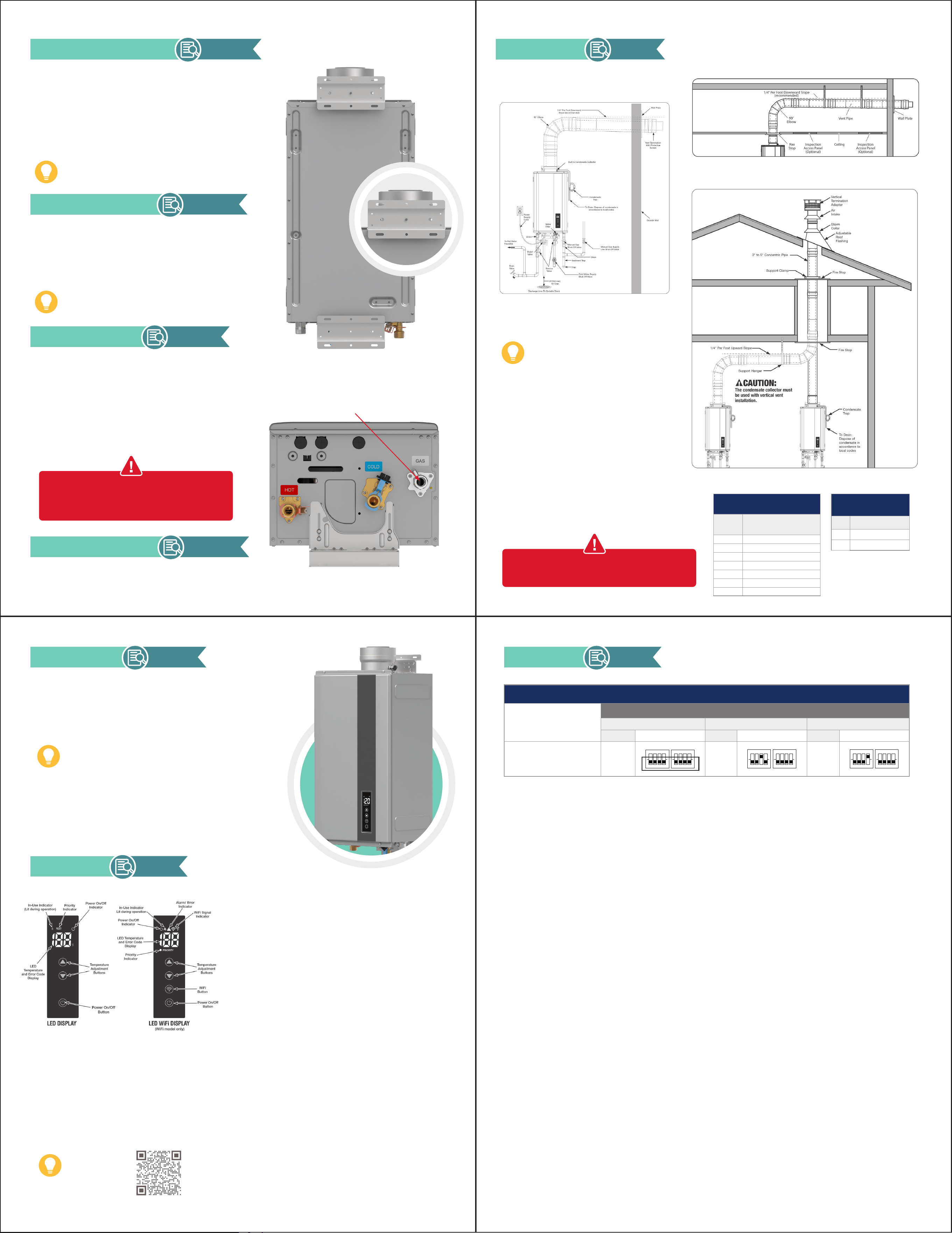
Please see Use & Care section Venting for
Direct-Vent Water Heater” Vent Lengths and DIP
switch Adjustments for details.
SINGLE UNIT: MAX. EQUIVALENT
VENT LENGTHS - STRAIGHT PIPE
Number of
90° Elbows
Max Length 3"/5" Straight Pipe
0 43 ft. (13.1 m)
1 41.5 ft. (12.6 m)
2 38.5 ft. (12.2 m)
3 34 ft. (11.7 m)
4 28 ft. (11.3 m)
5 20.5 ft. 10.8 m)
6 11.5 ft. (10.4 m)
EQUIVALENT FT. OF ELBOWS
3"/5"
90O 1.6 ft
45O 9 in.
Scan QR Code
to download the
EcoNet
®
App
(for applicable
models only)
DIP SWITCH
Settings
All Vent Lengths
Identify Vent Length
Identify Altitude
0 - 2,000 ft 2,001- 5,400 ft 5,400 - 7,800 ft
Setting Dip Setting Dip Setting Dip
All Vent Lengths
A
(Factory
Setting)
ON
1 2 3 4
ON
1 2 3 4
B
ON
1 2 3 4
ON
1 2 3 4
C
ON
1 2 3 4
ON
1 2 3 4
Scan for additional
information regarding
install, servicing, and
warranty registration.
TANKLESS EASY
INSTALLATION GUIDE
TIPS & MAINTENANCE
REGISTER YOUR 15 YEAR WARRANTY*
To register your product, scan the QR code located on the back cover.
You will need your unit model and serial numbers to complete this
process. These can be found on the label on the top panel inside of the
tankless water heater.
PRODUCT INFORMATION
MODEL: ________________________
SERIAL #: ________________________
INSTALL DATE: ___________________
INSTALLER INFORMATION
NAME: __________________________
COMPANY: ______________________
PHONE: _________________________
FLUSHING THE UNIT
To ensure the best continued performance from
your tankless water heater, we recommend cleaning
your unit every year to year and a half. This process
is called “flushing.” Please refer to proper flushing
procedures which can be found utilizing the QR
code below.
To make this servicing even easier for you to
remember, we’ve added a Maintenance Notification
Setting to remind you that it is time to flush via
a flashing code “88” on your tankless display or
through the EcoNet
®
App on your phone (Wi-Fi
Models Only).
DRAINING THE WATER HEATER
WARNING: IF THE BUILDING IS TO REMAIN
UNOCCUPIED FOR AN EXTENDED PERIOD, IT IS
RECOMMENDED THAT THE TANKLESS WATER
HEATER BE DRAINED TO PREVENT POSSIBLE
DAMAGE DUE TO FREEZING CONDITIONS.
IF YOU HAVE A PROBLEM OR ISSUE WITH THIS
WATER HEATER DO NOT RETURN, CALL FIRST.
Manufacturer National Service Department
1-866-720-2076
Draining the Water Heater
NOTE:
For Warranty Type, select “Standard”
for all tankless products. The owner is
required to provide proof of purchase/
ownership at the time of the claim.
Tips for Professional Installation & Product Setup
* All warranties void after 12,000 hours of operation. Warranty is provided to
original customer after online product registration under residential installation.
SETTING SERVICE ALERT HOURS
1. Press power button on the front control to turn off.
2. Turn off the gas and water by closing the shut-off
valves.
3. Press and hold the “▲” or “▼” button until “1Y” is
displayed
4. Press the “▲” or “▼” button until “8A ” is
displayed. Press and hold the power button on the
display for 1 second.
4. Press the “▲” or “▼” button to choose 50”, “75”,
“100” or “OF”.
BEFORE YOU BEGIN
TROUBLESHOOTING
If a problem occurs, the unit will stop operating and
display an error code. The most common error codes
on start-up are:
CLEARING ALARMS
1. Turn off all hot water faucets.
2. Turn off the water heater by pressing the Power
ON/OFF button.
3. Wait 5 minutes and then restart the water heater.
Press the POWER ON/OFF button.
4. Turn on a hot water faucet and check the display for
errors.
5. If the error remains, turn off the faucet and water
heater. Unplug the water heater from power source.
Wait 30 seconds and plug back in. Repeat steps 1
thru 4.
6. If error code still remains, turn off faucet and water
heater. Call for service assistance at the number listed
in the Customer Service box below.
This guide is designed to provide a high-level
installation overview and address key installation
questions. It is not intended to replace the
“Installation Instructions” in the Use & Care Manual
provided with the water heater. All instructions and
installation requirements as well as any local or
national codes, must be followed.
It is recommended that this product be installed
and serviced by a licensed plumber or a
professional service technician. Rheem is not
liable for any damages or defects resulting from
improper installation.
INSPECT SHIPMENT
• Check product for damage
• Ensure all pieces in box
Isolation Valves
Part # RTG20326
Gas Shutoff Valve
Part # RTG20074EH
Horizontal Vent Term.
Twin Pipe System
Part # RTG20281-1
Expansion Tank
Concentric Vent Term.
Twin Pipe System
Part # RTG20282
Recirculation Pump
Part # AP17920
GATHER KEY ACCESSORIES (SOLD SEPARATELY)
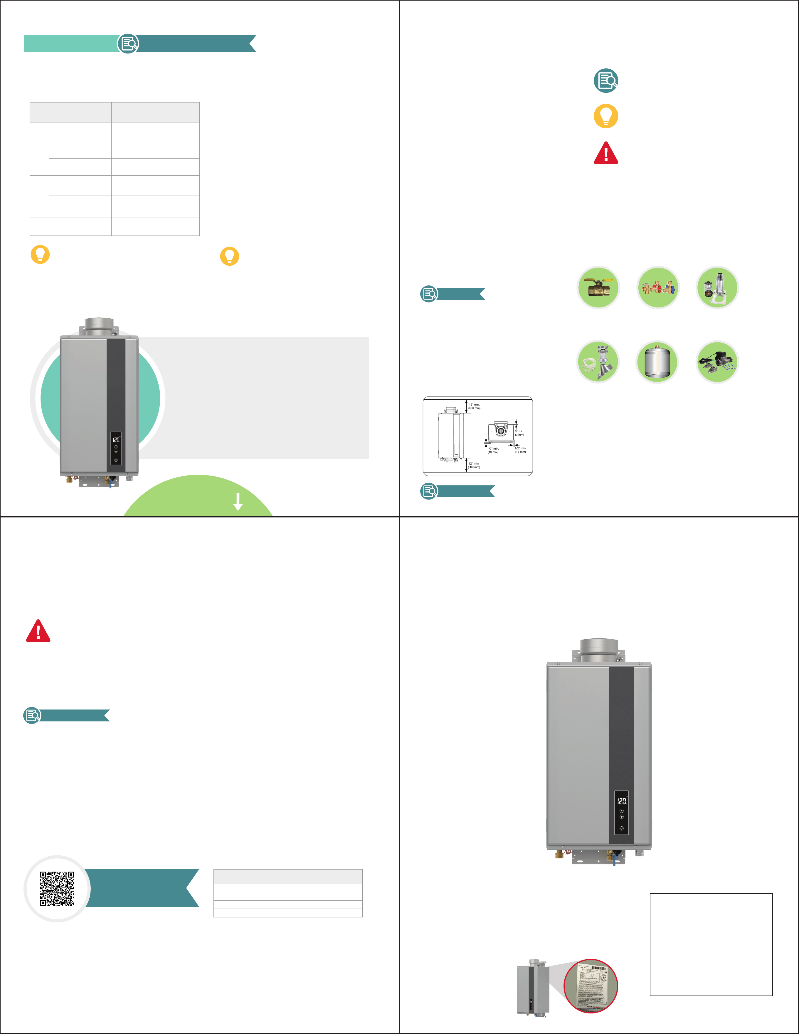
FIND INSTALL LOCATION
Consider The Following:
• Sturdy Wall
• Gas, Water, and Power supply
• Venting Termination
• Condensate Drain
• Enough space - see below
for minimum clearance required
(all models)
A SUCCESSFUL INSTALL STARTS HERE
This icon will tell you which section of the use
& care manual to check for more information
This icon will point out helpful Installation tips
This icon will point out information
that is key to a safe installation.
Inspect Product
Choosing a Location
TROUBLESHOOTING
Error Codes / Troubleshooting
OPEN TO VIEW
INSTALL GUIDE
Use QR code located on the back cover for
additional troubleshooting resources
Get the unit’s Model and Serial Numbers
ready and contact us: US 1.800.432.8373 /
Canada 1.800.268.6966
Be sure to have your Model and Serial
Numbers before calling customer service
(located on the water heater’s Rating Label)
CUSTOMER SERVICE/NEED HELP
HAVE QUESTIONS?
NEED HELP TROUBLESHOOTING?
(AP23366)
Error
Code
Possible
Cause
Solution
11
The gas shut-off valve is
not fully opened.
Check shut-off valve and open
completely.
12
Gas service has been
interrupted.
Check gas supply.
Low gas supply.
Contact a dealer or qualified service
technician.
90
Air intake or vent exhaust
opening may be blocked.
Remove any blockage. (Air intake
requires 12 in. [30 cm] of clearance.)
The vent pipes on the
vent termination may not
be connected properly.
Contact a dealer or qualified service
technician.
P1
Not enough water flow to
operate the unit.
Increase the water flow from the
fixtures.
Displayed Maintenance Notice Hour
50 500 hours
75 750 hours
100 1,000 hours
OF OFF
For all other codes not listed, please contact a
dealer or qualified service technician.