
MAX
®
Series Bass Ampliers
Operating
Manual
www.peavey.com

FCC Compliancy Statement
This device complies with Part 15 of the FCC rules. Operation is subject to the following two
conditions: (1) this device may not cause harmful interference, and (2) this device must accept any
interference received, that may cause undesired operation.
Warning: Changes or modications to the equipment not approved by Peavey Electronics Corp. can
void the user’s authority to use the equipment.
Note - This equipment has been tested and found to comply with the limits for a Class B digital device,
pursuant to Part 15 of the FCC Rules. These limits are designed to provide reasonable protection
against harmful interference in a residential installation. This equipment generates, uses and can radiate
radio frequency energy and, if not installed and used in accordance with the instructions, may cause
harmful interference to radio communications. However, there is no guarantee that interference will not
occur in a particular installation. If this equipment does cause harmful interference to radio or television
reception, which can be determined by turning the equipment o and on, the user is encouraged to try
and correct the interference by one or more of the following measures.
• Reorient or relocate the receiving antenna.
• Increase the separation between the equipment and receiver.
• Connect the equipment into an outlet on a circuit dierent from that to which the receiver is connected.
• Consult the dealer or an experienced radio/TV technician for help.
Peavey Electronics Corporation • 5022 Hartley Peavey Drive • Meridian, MS • 39305
(601) 483-5365 • FAX (601) 486-1278 • www.peavey.com • 80305796

ENGLISH
VENTILATION: For proper ventilation, allow 12" clearance from the nearest combustible surface.
All vents should have a minimum of 2" of free air space so air can flow thru the unit freely for proper cooling.
MAX
®
Series Bass Amplifiers
The Peavey MAX
®
Series is designed for superior tone, performance and reliability in portable bass amplification, with power ratings
up to 300 watts of power with Peavey’s DDT
™
speaker protection and exclusive tone enhancements.
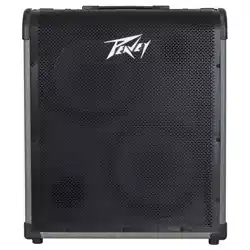
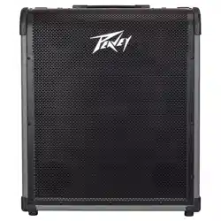
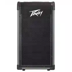
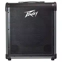
The Peavey MAX 100, MAX 150, MAX 208, MAX 250, and MAX 300 bass combo amps deliver huge bass tone with exclusive
Peavey designs, including unique psycho-acoustic low-end enhancement that adds bass without demanding anything extra from the
speaker—a testament to Peavey's technology-driven reliability. The EQ section includes three-band EQ, a gain boost featuring Peavey’s
patented TransTube
®
tube emulation circuitry, and switchable presets like Contour, Mid-Shift and Bright.
The MAX 100, MAX 150, MAX 250, and MAX 300 also feature a built-in chromatic tuner with mute, a tuned and ported enclosure,
1/8" headphone output and 1/8" auxiliary input. All models include an XLR direct output with ground lift, while the MAX 250 also
has a built-in tweeter.
Features: (vary according to model)
• Up to 300 watts of power
• Premium speakers
• DDT
™
speaker protection
• Pre-gain control with TransTube
®
gain boost
• ree-band EQ with Overdrive, Contour, Mid-Shi, Bright, and Kosmos-C switches
• Tuned, ported enclosures
• Kosmos-C low-end enhancement
• Precision balanced direct interface with ground li
• 1/8" aux input
• 1/8" headphones output
• Chromatic tuner with mute (not on 208)
• Unique cabinet design allows for superior high-frequency dispersion in tight spaces.

3
5 7 9 11 13 14
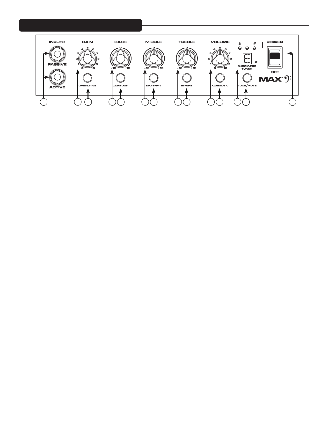
(1) ACTIVE/PASSIVE PICKUP Inputs
ese 1/4" inputs are included so you can choose the appropriate setting for your instrument. e gain structure of the amplier is
modied to accommodate the outputs of dierent pickup congurations. e PASSIVE input is 10dB hotter than the ACTIVE input.
(2) GAIN
is knob controls input level to the preamp.
(3) OVERDRIVE
is crunch circuit is designed so that the volume of the amp will not change when the boost is switched on, but the distortion level
will increase depending on the level of the GAIN knob. For best results, rst set the distortion amount by adjusting the GAIN. Next,
set the desired volume using the VOLUME knob. At this point, the clean volume will match if the Overdrive is turned o.
(4) BASS
is knob provides a shelving tone control for low frequencies and provides cut/boost of +/-15 dB. e center point is at. e center
frequency is 50 Hz. -3 dB shelf corner frequency is 100Hz.
(5) CONTOUR
is button boosts highs and lows while simultaneously cutting mid tones, producing a "scooped" sound.
(6) MIDDLE
is knob provides a peaking tone control for Mid frequencies and cut/boost of +/-15dB. e center point is at.
(7) MID SHIFT
is switch controls the center frequency of the MIDDLE knob. When the switch is OUT, the middle frequency is 600Hz. e middle
frequency is 250Hz when the switch is pushed IN.
(8) TREBLE
is knob provides a shelving tone control for high frequencies and cut/boost of +/-15dB. e center point is at and the frequency is
6 KHz. -3dB; the shelf corner frequency is 4 KHz.
(9) BRIGHT SWITCH
is button provides a 10 dB boost to frequencies above 1KHz. To activate, depress the switch to its “IN” position.
(10) VOLUME
is knob controls the overall volume of the amplier.
(11) KOSMOS-C Subharmonic Generator
is Kosmos-C Low enhancement works by creating harmonics of signals in the bottom octave, where speakers are usually ineec-
tive. e harmonics are more easily reproduced, resulting in a perception of stronger bass. e eect is source dependent; obviously a
source with little energy in the bottom octave will not create booming bass.
(12) CHROMATIC TUNER (Not on Max 208)
Pressing the TUNE/MUTE button (13) will engage the chromatic tuner while muting the output to the speaker. e LED screen will
indicate which note is being played while the red and green LEDs above the screen indicate whether the note is at (red), sharp
(red) or in tune (green).
Control Panel MAX
®
Series
1
4
6 8 10 12
2

Rear Panel
(13) TUNE/MUTE (not available on Max 208)
Pressing this button will engage the chromatic tuner while muting the output to the speaker. e LED screen will indicate which note
is being played while the red and green LEDs above the screen indicate whether the note is at (red), sharp (red) or in tune (green).
is switch also mutes the DI.
(14) POWER SWITCH
15
16
23
21
19
1817
20
22
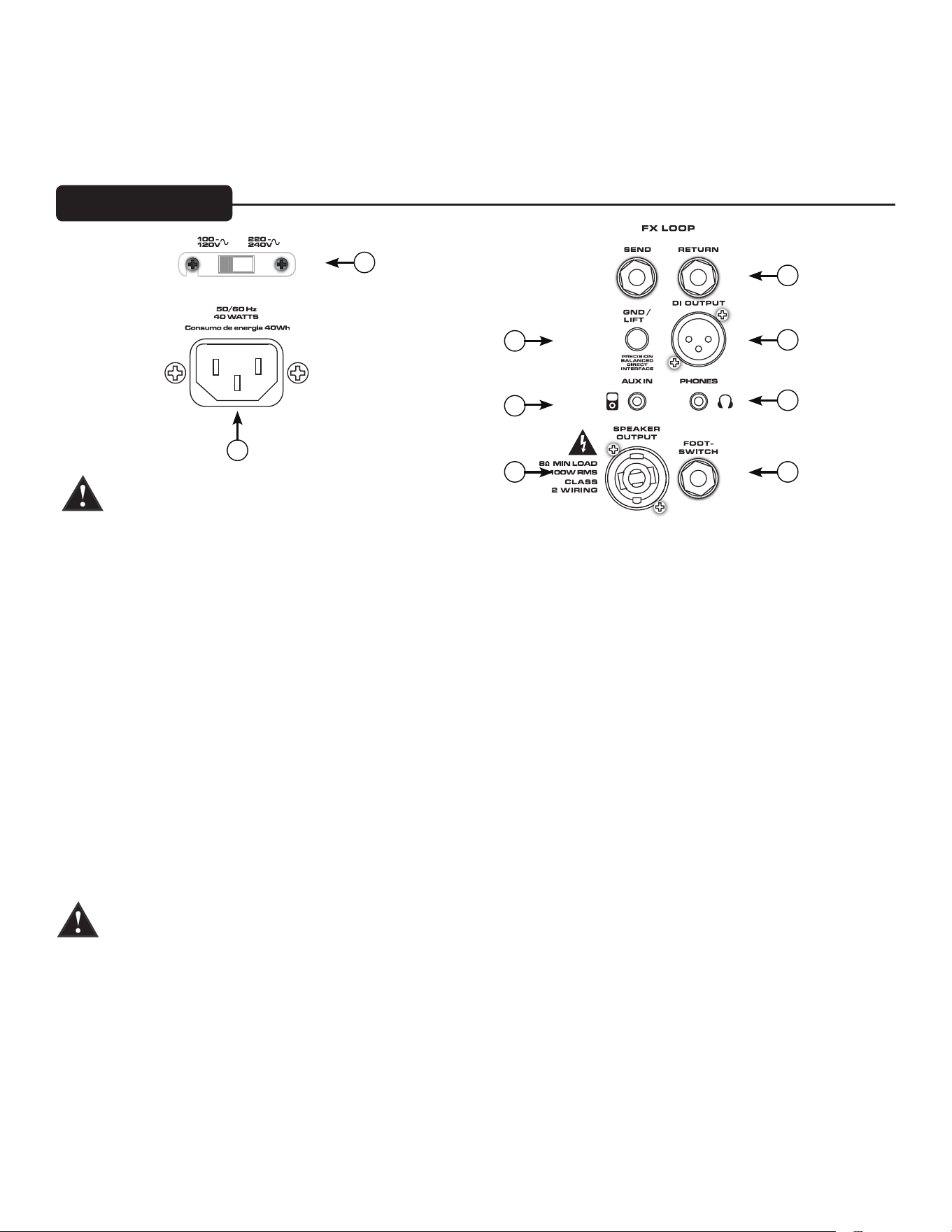
(15) AC POWER INLET:
is is the receptacle for an IEC line cord, which provides AC power to the unit. Connect the line cord to this connector to provide
power to the unit. Damage to the equipment may result if improper line voltage is used. (See line voltage marking on unit).
Never break o the ground pin on any equipment. It is provided for your safety. If the outlet used does not have a ground pin, a suitable
grounding adapter should be used, and the third wire should be grounded properly. To prevent the risk of shock or re hazard, always
make sure that the amplier and all associated equipment is properly grounded.
NOTE: FOR UK ONLY
As the colors of the wires in the mains lead of this apparatus may not correspond with the colored markings identifying the terminals
in your plug, proceed as follows: (1) e wire that is colored green and yellow must be connected to the terminal that is marked by
the letter E, or by the Earth symbol, or colored green or green and yellow. (2) e wire that is colored blue must be connected to the
terminal that is marked with the letter N, or the color black. (3) e wire that is colored brown must be connected to the terminal that
is marked with the letter L, or the color red.
(16) LINE VOLTAGE SELECT SWITCH
is selector switch allows the amplier to be operated at dierent line voltages. Please be sure this switch is set to the
proper voltage for your area before connecting the amplier to a power source or turning the amplier on for the rst time.
NEVER CHANGE THE POSITION OF THIS SWITCH WHILE THE AMPLIFIER IS TURNED ON.
(17) SPEAKER OUTPUT JACK (Max 150, 250, and 300 only)
is combination 1/4" / twist-lock connector is used to connect a speaker cable to the amplier. e minimum load impedance on the
amplier is 8Ω.
(18) FOOTSWITCH JACK
e optional footswitch (part number 03022910) plugs into this jack. e footswitch controls OVERDRIVE and MUTE.
(19) HEADPHONE OUTPUT
1/8" headphone output for personal monitoring.
(20) AUX INPUT
is 1/8" input jack allows you to connect a CD player or MP3 player to your MAX® Series bass amp and play along

(21) PRECISION BALANCED DIRECT INTERFACE
is XLR output is used to connect the Max pre amp section to external equipment, such as mixing consoles, external power ampliers,
or recording equipment. is novel circuit provides a perfectly balanced and noise-free signal with none of the problems associated
with small transformers.
(22) DI GND LIFT SWITCH
is switch may be used to eliminate hum caused by ground loops between the amplier and other equipment, such as a mixing con-
sole.
(23) FX LOOP
e eects loop consists of the SEND and RETURN jacks, which are used to patch external eects processors post EQ in the signal
chain. Connect the SEND jack to the input of eects processors. Connect the RETURN jack to the output of eects processors. e EF-
FECTS SEND and RETURN jacks can also be used as a line level unbalanced preamp output and power amp input jacks, respectively.

POWER CONSUMPTION:
(1/8 rated power, 1KHz sine wave)
120vac/60Hz, 230vac/50Hz
MAX 208 = 33W
MAX 100 = 50W
MAX 150 = 33W
MAX 250 = 63W
MAX 300 = 78W
POWER AMPLIFIER:
(Rated Power)--Continuous RMS
(1% THD, 1KHz sine wave, nominal line)
MAX 100 = 60 W (rms) into 8 ohms
MAX 150 = 120 W (rms) into 4 ohms
MAX 250 = 150 W (rms) into 4 ohms
MAX 300 = 200 W (rms) into 3 ohms
MAX 208 = 120 W (rms) into 4 ohms
PRE-AMPLIFIER:
Maximum Input Sensitivity:
(PRE GAIN = 10, LOW/MID/HIGH = 5, VOLUME = 10, all voicing switches defeated)
Passive Input 11mV / -36.95dBu 30mV / -28.24dBu 40mV / -25.74dBu
Active Input same as passive 90mV / -18.70dBu 110mV / -16.95dBu
Auxiliary Input 420mV / -5.32dBu 900mV / 1.3dBu 1.0V / 2.22dBu
Nominal Input Sensitivity:
(PRE GAIN = 5, LOW/MID/HIGH = 5, VOLUME = 5, all voicing switches defeated)
Passive Input 290mV / -8.53dBu 400mV / -5.74dBu 500mV / -3.8dBu
Active Input same as passive 1.10V / 3.05dBu 1.40V / 5.14dBu
Auxiliary Input same as maximum 1.80V / 7.32dBu 2.10V / 8.66dBu
Headphone Output:
(Mono)
50mW x 2 into 8-ohm minimum load
Direct Interface (DI):
Pre-EQ, unity buer
Output Signal Level = Input Level – 10dB
Noise Floor = 0.95mV(rms) = -78dBu
Dimensions:
(HxWxD)
Max 100 – 18.0”x15.7”x13.2” – 23.8lb
Max 150 – 19.0”x16.5”x14.2” – 29.2lb
Max 208 – 23.2”x12.3”x13.2” – 32.2lb
Max 250 – 22.8”x19.4”x16.2” – 44.4lb
Max 300 – 22.8”x19.4”x16.2” – 46.4lb
Rear Panel

Logo referenced in Directive 2002/96/EC Annex IV
(OJ(L)37/38,13.02.03 and defined in EN 50419: 2005
The bar is the symbol for marking of new waste and
is applied only to equipment manufactured after
13 August 2005
www.peavey.com
Warranty registration and information for U.S. customers available online at
www.peavey.com/warranty
or use the QR tag below
Features and specications subject to change without notice.
Peavey Electronics Corporation 5022 Hartley Peavey Drive Meridian, MS 39305 (601) 483-5365 FAX (601) 486-1278
MAX
®
系列低音放大器
操作
手册
www.peavey.com

中文
通风:为确保适当的通风,离最近的可燃面要保持12"间隔。
所有通风散热口应有至少2"的自由空间,使空气能流畅通贯机柜,确保适当的冷却。
MAX
®
系列低音放大器
Peavey(百威)的MAX
®
系列专为便携式低音设计,具有卓越的音质、性能及可靠性,其额定功率高达300瓦,具有
Peavey(百威)的DDT
™
扬声器保护和独特的音质增强功能。
Peavey(百威)MAX 100、MAX 150、MAX 208、MAX 250和MAX 300低音组合放大器所输出的强大低音调带着
Peavey(百威)特有的设计——独一无二的心理声学低端增强,可在不增加任何扬声器额外负荷的条件下加强低音—是
Peavey(百威)技术导向型可靠性的一个见证。均衡部分有一个三段均衡器,采用Peavey(百威)拥有专利的TransTube
®
电子管模拟电路和可切换Contour(轮廓)、Mid-Shift(中音扫频)、Bright(明亮)等预设置的增益提升。
MAX 100、MAX 150、MAX 250和MAX 300还配备了一个带有静音的内置半音阶调谐器、精心调制的带端口机柜、1/8"耳
机输出和1/8"辅助输入。所有型号都包括带接地开关的 XLR 直接输出,而 MAX 250 更配备了一个内置高音扬声器。
功能:(因型号而异)
• 高达300瓦的功率
• 优质扬声器
• DDT
™
扬声器保护
• 带TransTube
®
增益提升的前级增益控制
• 三段均衡器,具有Overdrive(过载)、Contour(轮廓)、Mid-Shift(中音扫频)、Bright(明亮)和Kosmos-C开关功
能
• 经过精心调制的带端口机柜
• Kosmos-C低端增强
• 带接地断离开关的精确平衡直接接口
• 1/8" 辅助输入
• 1/8" 耳机输出
• 带静音半音阶调谐器(不包括208)
• 独特的机柜设计允许在狭小空间中实现卓越的高频分散。

3 5 7 9
11 13 14
(1) ACTIVE/PASSIVE PICKUP (有源/无源拾音)输入
这些1/4”输入可以让您为设备选择适当的设置。对放大器的增益结构作出调整,以适应不同拾音配置的输出。PASSIVE(
无源)输入比ACTIVE(有源)输入热10dB。
(2)GAIN(增益)
此旋钮控制前置功放的输入音量。
(3)OVERDRIVE(过载)
这个crunch(嘎吱音)电路确保打开提升时放大器的音量不会改变,但失真电平会随着GAIN(增益)旋钮的电平而增加。
为达到最佳效果,首先要通过调整GAIN(增益)来设置失真量。然后用(音量)旋钮来设置期望的音量。这时候,如果
Overdrive(过载)不开启,匹配的是净音量。
(4)BASS(低音)
此旋钮提供低音频率+/-15dB削减/提升缓倾音调控制,中心点是降音调模式。中心频率为50Hz,-3dB 倾斜转角频率为
100Hz。
(5)CONTOUR(轮廓)
此按钮在削减中音的同时提升高音和低音,产生一个“勺”形(中音衰减型均衡形)声音。
(6)MIDDLE(中音)
此旋钮给中音频率提供一个+/-15dB削减/提升的峰值音调控制,中心点是降音调模式。
(7) MID SHIFT(中音扫频)
这个开关控制MIDDLE(中音)旋钮的中心频率。当开关处于OUT时,中心频率为600Hz。而当开关被按下至IN时,中心频
率则为250Hz。
(8)TREBLE(高音)
此旋钮给高音频率提供倾斜音调控制及+/-15dB削减/提升,中心点是降音调模式,频率为6 KHz。-3dB; 倾斜转角频率为4
KHz。
(9) BRIGHT (明亮)开关
此按钮在1KHz频率以上提供10dB的提升。将开关按至“IN”的位置启动。
(10)VOLUME(音量)
此旋钮控制放大器的总体音量。
(11) KOSMOS-C 次谐波发生器
该 Kosmos-C 低端增强通过在最低八度音中产生信号谐波来实现,这种音调下扬声器一般无效。谐波更容易被复制,造成
更强低音的感觉。此音效依赖于音源;显然在最低八度音中几乎没有能量的声源是不能产生隆隆低音的。
(12) CHROMATIC TUNER(半音阶调音器)(Max 208型号不提供)
按下TUNE/MUTE(调谐/静音)按钮(13)将打开半音阶调谐器,同时静音进入扬声器的输出。LED显示屏显示正在演奏的音
调,而显示屏上方的红色和绿色LED指示灯则显示音调是降调(红色)、升调(红色)、还是合调(绿色)。
控制面板 MAX
®
系列
1
4 6 8
10 12
2

后面板
(13) 调谐/静音(Max 208型号不提供)
按下这个按钮将打开半音阶调谐器,同时静音进入扬声器的输出。LED显示屏显示正在演奏的音调,而显示屏上方的红色和
绿色LED指示灯则显示音调是降调(红色)、升调(红色)、还是合调(绿色)。
这个开关还静音DI(直接接口)。
(14) POWER开关
15
16
23
21
19
1817
20
22
(15) AC电源插口:
这是IEC(国际电工委员会)电源线插座,向设备提供交流电源。将电源线与该连接器相连即可为设备提供电源。如果使用
不当电压,可能导致设备损坏。(参见设备上标明的电源电压)。
千万不要折断任何设备上的接地脚。这是为了您的安全起见。如果使用的电源插座没有接地脚,则应使用相应的接地转换
器,并将第三根导线正确接地。为防止触电或火灾危险,一定要确认放大器及其所有附加设备都正确接地。
NOTE: FOR UK ONLY
As the colors of the wires in the mains lead of this apparatus may not correspond with the colored markings identifying the
terminals in your plug, proceed as follows: (1) The wire that is colored green and yellow must be connected to the terminal
that is marked by the letter E, or by the Earth symbol, or colored green or green and yellow. (2) The wire that is colored
blue must be connected to the terminal that is marked with the letter N, or the color black. (3) The wire that is colored
brown must be connected to the terminal that is marked with the letter L, or the color red.
(16) LINE VOLTAGE SELECT(线路电压选择)开关
该选择器允许放大器在不同线路电压下操作。在将放大器连接到电源或首次打开放大器之前请确保将此开关设置到您所在地
的电压。
打开放大器时切勿改变此开关的位置。
注意!
(17) 扬声器输出插孔(仅适用于Max 150、250和300)
这一组合1/4”/扭锁连接器用于将扬声器电缆连接到放大器上。放大器上的最低负荷阻抗为8Ω。
(18) FOOTSWITCH 插座
在该插座中插入可选脚踏开关(部件编号 03022910)。此脚踏开关控制OVERDRIVE(过载)和MUTE(静音)。
(19) 耳机输出:
1/8"耳机输出,供个人监听用。
(20) AUX INPUT(辅助输入)
这个1/8"输入插孔可让您将一台CD播放器或MP3播放器连接到MAX
®
系列低音放大器一起播放。

(21) PRECISION BALANCED DIRECT INTERFACE(精确平衡直接接口)
这一XLR输出用于将Max的前置放大器部分连接到外部设备,比如调音台、外部功率放大器或录音设备。该新型电路提供了
一个完美的平衡和无噪声信号,免于小型变压器的常见问题。
(22) DI GND LIFT (接地断离直接接口)开关
这个开关可以被用来消除因放大器与调音台等其它设备之间的接地回路而造成的哼声。
(23) FX LOOP(FX 回路)
此效果回路由SEND(发送)和RETURN(返回)插孔组成,用于在信号链中修补外部效果处理器的前级均衡器。将SEND
(发送)插孔连接到效果处理器的输入端。将RETURN(返回)插孔连接到效果处理器的输出端。EFFECTS SEND(效果发送)
和RETURN(返回)插孔还可以分别用作线路电平非平衡前置功放输出和功放输入插孔。

POWER CONSUMPTION(功耗):
(1/8额定功率,1KHz正弦波)
120伏交流电/60Hz,230伏交流电/50Hz
MAX 208 = 33瓦
MAX 100 = 50瓦
MAX 150 = 33瓦
MAX 250 = 63瓦
MAX 300 = 78瓦
功率放大器:
(额定功率)--连续 RMS
(1% 总谐波失真,1KHz正弦波,标称线)
MAX 100 = 60瓦(rms),8欧姆
MAX 150 = 120瓦(rms),4欧姆
MAX 250 = 150瓦(rms),4欧姆
MAX 300 = 200瓦(rms),3欧姆
MAX 208 = 120瓦(rms),4欧姆
前级放大器:
最大输入灵敏度:
(前级增益 = 10,低音/中音/高音 = 5,音量 = 10,关闭所有音频开关)
无源输入 11mV / -36.95dBu 30mV / -28.24dBu 40mV / -25.74dBu
有源输入 同无源输入 90mV / -18.70dBu 110mV / -16.95dBu
辅助输入 420mV / -5.32dBu 900mV / 1.3dBu 1.0V / 2.22dBu
额定输入灵敏度:
(前级增益 = 5,低音/中音/高音 = 5,音量 = 10,关闭所有音频开关)
无源输入 290mV / -8.53dBu 400mV / -5.74dBu 500mV / -3.8dBu
有源输入 同无源输入 1.10V / 3.05dBu 1.40V / 5.14dBu
辅助输入 同最大输入 1.80V / 7.32dBu 2.10V / 8.66dBu
耳机输出:
(单声道)
50毫瓦 x 2,8欧姆最低负载
直接接口(DI):
前级均衡,单位缓冲
输出信号电平 = 输入电平 – 10dB
本底噪音 = 0.95毫伏(有效值) = -78dBu
外形尺寸:
(HxWxD)
Max 100 – 18.0”x15.7”x13.2” – 23.8lb
Max 150 – 19.0”x16.5”x14.2” – 29.2lb
Max 208 – 23.2”x12.3”x13.2” – 32.2lb
Max 250 – 22.8”x19.4”x16.2” – 44.4lb
Max 300 – 22.8”x19.4”x16.2” – 46.4lb
后面板

Logo referenced in Directive 2002/96/EC Annex IV
(OJ(L)37/38,13.02.03 and defined in EN 50419: 2005
The bar is the symbol for marking of new waste and
is applied only to equipment manufactured after
13 August 2005
www.peavey.com
Warranty registration and information for U.S. customers available online at
www.peavey.com/warranty
or use the QR tag below
Peavey Electronics Corporation 5022 Hartley Peavey Drive Meridian, MS 39305 (601) 483-5365 FAX (601) 486-1278

Amplificateurs série MAX
®
Mode
d'emploi
www.peavey.com

FRANCAIS
VENTILATION : Laissez un espace de 12" de la surface combustible la plus proche pour assurer une bonne ventilation.
Tous les évents doivent avoir un espace libre minimum de 2" afin que l’air puisse circuler librement dans l’appareil pour son
bon refroidissement.
Amplificateurs de la gamme MAX
®
La série MAX
®
de Peavey est conçue pour avoir une tonalité, une performance et une fiabilité supérieures pour l'amplification portable
des basses, avec une puissance assignée jusqu'à 300watts avec la protection DDT
™
de Peavey et des améliorations exclusives de tonalité.
Les amplificateurs de basses combinés MAX 100, MAX 150, MAX 208, MAX 250 et MAX 300 de Peavey fournissent une incroyable
tonalité de basses avec des conceptions exclusives de Peavey, notamment une amélioration psychoacoustique d'entrée de gamme
unique qui ajoute des basses sans demande supplémentaire du haut-parleur: un témoignage de la fiabilité technologique de Peavey. La
section d'égaliseur comprend un égaliseur à trois bandes, une augmentation du gain grâce aux circuits d'émulation de tube brevetés
TransTube
®
, et des préréglages à baculement tels que Contour, Mid-Shift et Bright.
Le MAX100, le MAX150, le max 250 et le MAX300 sont également dotés d'un accordeur chromatique intégré avec sourdine, une
enceinte configurée à évent, une sortie casque de 3mm et une entrée auxiliaire de 3mm. Tous les modèles incluent la sortie directe
XLR avec ground lift, et le MAX 250 a un tweeter intégré.
Caractéristiques : (dépendent du modèle)
• Jusqu'à 300watts de puissance
• Haut-parleurs haut de gamme
• Protection DDT
™
des haut-parleurs
• Contrôle de pré-gain avec amélioration de gain TransTube
®
• Égaliseur tribande avec sélecteurs Overdrive, Contour, Mid-Shi, Bright, et Kosmos-C
• Enceintes congurées et à évent
• Amélioration basses fréquences Kosmos-C
• Interface directe équilibrée avec précision, avec ground li
• Entrée aux de 3mm
• Sortie casque de 3mm
• Égaliseur chromatique avec muet (pas sur le 208)
• Conception de boîtier unique permettant une meilleure dispersion des hautes fréquences dans les espaces fermés.
3 5 7 9 11 13 14
(1) Entrées de MICRO ACTIF/PASSIF
Ces entrées 6,3mm (1/4) vous permettent de choisir le réglage correspondant à votre instrument. La structure du gain de l’amplica-
teur est modiée pour s’adapter aux sorties des diérentes congurations de collecte. L’entrée PASSIVE est plus chaude de 10 dB que
l’entrée ACTIVE
(2) GAIN
Cette molette contrôle le niveau d’entrée de l’instrument.
(3) OVERDRIVE
Ce circuit de suppression est conçu an que le volume de l’amplicateur ne change pas lorsque l’augmentation est activée, mais le
niveau de distorsion augmentera en fonction du niveau du GAIN. Pour de meilleurs résultats, réglez d’abord le niveau de distorsion en
réglant le GAIN. Ensuite, réglez le volume souhaité avec le bouton VOLUME. Maintenant, le volume net correspondra si Overdrive est
désactivé.
(4) BASSES
Ce bouton permet un contrôle de la tonalité en dégradé pour les basses fréquences et fournit une atténuation/augmentation de ±
15dB. Le point central est plat. La fréquence centrale est de 50 Hz. La fréquence d’angle en dégradé de -3dB est de 100Hz.
(5) CONTOUR
Ce bouton augmente les hauts est les bas tout en coupant simultanément les tons moyens, produisant un son «scooped».
(6) MIDDLE
Ce bouton permet un contrôle de la tonalité en pics pour les fréquences moyennes et une atténuation/augmentation de ± 15dB. Le
point central est plat.
(7) MID SHIFT
Ce bouton contrôle la fréquence centrale du bouton MIDDLE (moyen). Lorsque le bouton est sur OUT, la fréquence moyenne est de
600Hz. La fréquence moyenne est de 250Hz lorsque le bouton est sur IN.
(8) TREBLE
Ce bouton permet un contrôle de la tonalité en dégradé pour les hautes fréquences et une atténuation/augmentation de ± 15dB. Le
point central est plat et la fréquence est de 6 KHz. La fréquence d’angle en dégradé de -3dB est de 4 KHz.
(9) BOUTON BRIGHT
Ce bouton permet une augmentation de 10dB aux fréquences supérieures à 1kHz. Pour l’activer, mettez le bouton en position «IN».
(10) VOLUME
Ce bouton contrôle le volume global de l’amplicateur.
(11) Générateur sous-harmonique de KOSMOS-C
Cette amélioration basse Kosmos-C fonctionne en créant des harmoniques de signaux dans l’octave du bas, dans laquelle lest haut-
parleurs sont généralement inecaces. Les harmoniques sont plus aisément reproduites, résultant en une perception de basses plus
fortes. L’eet est dépendant de la source, car il est évident qu’une source à petite énergie dans l’octave du bas ne réussira pas à créer des
basses explosives.
(12) ACCORDEUR CHROMATIQUE (Pas sur le Max 208)
Une pression sur le bouton ACCORDER/MUET (13) permet d’activer l’accordeur chromatique tout en mettant en sourdine la sortie
du haut-parleur. L’écran LED achera la note jouée, alors que les LED rouge et vert au-dessus de l’écran indiquent si la note est en
bémol (rouge), en dièse (rouge) ou juste (vert).
Panneau de contrôle de la série MAX
®
1
4 6 8 10 12 2

Panneau arrière
(13) ACCORDER/MUET (Pas sur le Max 208)
Ce bouton permet d’activer l’accordeur chromatique tout en mettant en sourdine la sortie du haut-parleur. L’écran LED achera la note
jouée, alors que les LED rouge et vert au-dessus de l’écran indiquent si la note est en bémol (rouge), en dièse (rouge) ou juste (vert).
Ce bouton met également le DI en sourdine.
(14) INTERRUPTEUR MARCHE/ARRÊT
15
16
23
21
19
18 17
20
22
(15) ENTRÉE D'ALIMENTATION AC:
Ceci est la prise prévue pour un cordon d’alimentation IEC qui fournit l’alimentation CA à l’appareil. Branchez le cordon d’alimentation
à cette prise pour alimenter l’appareil. L’équipement peut être endommagé si un cordon ce tension incorrecte est utilisé. (voir la plaque
signalétique sur l’appareil de la tension de ligne).
Veillez à ne jamais casser la broche de terre sur tous appareils. Ce dispositif est prévu pour votre sécurité. Si la prise de courant est dé-
pourvue de broche de terre, un adaptateur de mise à la terre approprié doit être utilisé et le troisième l doit être mis à la terre convena-
blement. Pour éviter tout risque de choc électrique ou d’incendie, veillez toujours à ce que l’amplicateur et tous les équipements reliés
soient correctement mis à la terre.
NOTE: FOR UK ONLY
As the colors of the wires in the mains lead of this apparatus may not correspond with the colored markings identifying the terminals
in your plug, proceed as follows: (1) e wire that is colored green and yellow must be connected to the terminal that is marked by
the letter E, or by the Earth symbol, or colored green or green and yellow. (2) e wire that is colored blue must be connected to the
terminal that is marked with the letter N, or the color black. (3) e wire that is colored brown must be connected to the terminal that
is marked with the letter L, or the color red.
(16) BOUTON DE SELECTION DE TENSION DE LIGNE
Ce bouton de sélection permet à l’amplicateur de fonctionner sous diérentes tensions de ligne. Veillez à régler ce commutateur sur la
tension appropriée à votre région avant de brancher l’amplicateur à la source électrique ou de l’allumer pour la première fois.
NE JAMAIS MODIFIER LA POSITION DE CE BOUTON SI L’AMPLIFICATEUR EST SOUS TENSION.
(17) JACK DE SORTIE HAUT-PARLEUR (Max 150, 250, et 300 seulement)
Ce connecteur combiné 1/4" verrou tournant est utilisé pour brancher le câble de haut-parleur à l’amplicateur. L’impédance de charge
minimum de l’amplicateur est de 8 Ω.
(18) JACK DE PÉDALES
La pédale en option (pièce numéro 03022910) se branche dans cette prise. La pédale contrôle les fonctions OVERDRIVE et MUET.
(19) SORTIE CASQUE
Sortie casque de 3,5mm (1/8”) pour un suivi personnel.

(20) ENTRÉE AUX
Cette prise d'entrée de 3mm sert à brancher un lecteur CD ou MP3 sur votre amplicateur de basses de la série MAX®.
(21) INTERFACE DIRECTE ÉQUILIBRÉE AVEC PRÉCISION
Cette sortie XLR est utilisée pour connecter la section de préamplication du Max à un équipement externe, tel que consoles de
mixage, amplicateurs de puissance externe ou équipement d’enregistrement. Ce circuit inovant ore un signal parfaitement équilibré
et sans bruit sans aucun des problèmes associés aux petits transformateurs.
(22) COMMUTATEUR DI GND LIFT
Ce commutateur peut être utilisé pour éliminer le bourdonnement causé par des boucles de masse entre l’amplicateur et un autre
équipement, tel qu’une console de mixage.
(23) BOUCLE D’EFFET
La boucle d’eet comprend des prises de DÉPART et de RETOUR, qui sont utilisées pour acheminer le signal d’un égaliseur de traite-
ment d’eets externe, après commande de volume, dans la chaîne du signal. Connectez la prise de DÉPART à l’entrée des processeurs
d’eets. Connectez la prise de RETOUR à la sortie des processeurs d’eets. Les jacks DÉPART et RETOUR D’EFFET peuvent également
servir de sortie de préamplication de niveau ligne et de jack d’alimentation de jack, respectivement.

CONSOMMATION ÉLECTRIQUE:
(puissance nominale 1/8, onde sinusoïdale de 1kHz)
120VCA/60Hz, 230VCA/50Hz
MAX208 = 33W
MAX100 = 50W
MAX150 = 33W
MAX250 = 63W
MAX300 = 78W
AMPLIFICATEUR DE PUISSANCE:
(Puissance acceptée)--RMS continu
(1% THD, onde sinusoïdale de 1KHz, alimentation nominale)
MAX 100 = 60 W (rms) sous 8 ohms
MAX 150 = 120 W (rms) sous 4 ohms
MAX 250 = 150 W (rms) sous 4 ohms
MAX 300 = 200 W (rms) sous 3 ohms
MAX 208 = 120 W (rms) sous 4 ohms
PRÉAMPLIFICATEUR:
Sensibilité d’entrée maximale:
(PRÉ-GAIN = 10, BAS/MOY/HAUT = 5, VOLUME = 10, tous les commutateurs vocaux désactivés)
Entrée passive 11mV / -36,95dBu 30mV / -28,24dBu 40mV / -25,74dBu
Entrée active identique à la passive 90mV / -18,70dBu 110mV / -16,95dBu
Entrée auxiliaire 420mV / -5,32dBu 900mV / 1,3dBu 1,0V / 2,22dBu
Sensibilité d’entrée nominale:
(PRÉ-GAIN = 5, BAS/MOY/HAUT = 5, VOLUME = 5, tous les commutateurs vocaux désactivés)
Entrée passive 290mV / -8,53dBu 400mV / -5,74dBu 500mV / -3,8dBu
Entrée active identique à la passive 1,10V / 3,05dBu 1,40V / 5,14dBu
Entrée auxiliaire identique à la maximum 1,80V / 7,32dBu 2,10V / 8,66dBu
Sortie casque:
(Mono)
50mW x 2 sous une charge minimum de 8Ω
Interface directe (DI):
Pré-égaliseur, tampon de l'appareil
Niveau du signal de sortie = niveau de l'entrée – 10dB
Niveau de bruit de fond = 0,95mV (rms) = -78dBu
Dimension:
(HxlxP)
Max 100 – 18,0”x15,7”x13,2” – 23,8lb
Max 150 – 19,0”x16,5”x14,2” – 29,2lb
Max 208 – 23,2”x12,3”x13,2” – 32,2lb
Max 250 – 22,8”x19,4”x16,2” – 44,4lb
Max 300 – 22,8”x19,4”x16,2” – 46,4lb
Panneau arrière

Logo referenced in Directive 2002/96/EC Annex IV
(OJ(L)37/38,13.02.03 and defined in EN 50419: 2005
The bar is the symbol for marking of new waste and
is applied only to equipment manufactured after
13 August 2005
www.peavey.com
Warranty registration and information for U.S. customers available online at
www.peavey.com/warranty
or use the QR tag below
Peavey Electronics Corporation 5022 Hartley Peavey Drive Meridian, MS 39305 (601) 483-5365 FAX (601) 486-1278

Bassverstärker Serie MAX
®
Betriebs-
anleitung
www.peavey.com

DEUTSCH
BELÜFTUNG: Halten Sie für angemessene Lüftung einen Abstand von 30 cm von der nächsten brennbaren Oberfläche ein.
Alle Ventilationsöffnungen sollten einen freien Luftraum von mindestens 5 cm haben, damit die Luft für angemessene
Kühlung frei durch das Gerät fließen kann.
Bassverstärker Serie
MAX
®
Die Serie Peavey MAX
®
ist entworfen für besseren Klang, bessere Leistung und Zuverlässigkeit in transportierbarer Bassverstärkung,
mit Nennleistungen bis zu 300 W mit dem Lautsprecherschutz DDT
™
von Peavey und mit exklusiver Klangverbesserung.
Die Bass-Komboverstärker MAX 100, MAX 150, MAX 208 und MAX 300 von Peavey liefern einen enormen Bassklang mit
exklusivem Peavey-Design, einschließlich psychoakustischer Verbesserung am unteren Ende, die Bässe hinzufügt, ohne mehr vom
Lautsprecher zu verlangen – ein Testament für die technologisch getriebene Zuverlässigkeit von Peavey. Der EQ-Abschnitt enthält
einen 3-Band-EQ, einen Gain Boost mit den patentierten TransTube
®
-Röhrenemulationskreisen von Peavey und umschaltbare
Voreinstellungen wie Contour, Mid-Shift und Bright.
MAX 100, MAX 150, MAX 250 und MAX 300 haben auch einen eingebauten chromatischen Tuner mit Stummschaltung, ein
abgestimmtes und mit Öffnungen versehenes Gehäuse, einen 1/8“ Kopfhörerausgang und einen 1/8“ AUX-Eingang. Alle Modelle
verfügen über einen XLR-Direktausgang mit Ground-Lift, während der MAX 250 auch einen eingebauten Hochtöner besitzt.
Merkmale: (variieren je nach Modell)
• Bis zu 300 W Nennleistung
• Hochleistungslautsprecher
• DDT
™-
Lautsprecherschutz
• Vorverstärkungsregelung mit Transtube
®
Gain Boost
• Drei-Band-EQ mit Overdrive-, Contour-, Mid-Shi-, Bright- und Kosmos-C-Schaltern
• Abgestimmte und mit Önungen versehene Gehäuse
• Kosmos-C Low-End-Verbesserung
• Präzisionsausgeglichene, direkte Schnittstelle mit Ground-Li
• 1/8“ AUX-Eingang
• 1/8“ Kopörerausgang
• Chromatischer Tuner mit Stummschaltung (nicht bei Modell 208)
• Das einzigartige Gehäusedesign ermöglicht eine hervorragende Hochfrequenzstreuung in engen Räumen.

3 5 7 9 11 13 14
(1) Eingänge ACTIVE/PASSIVE PICKUP
Diese 1/4“ Eingänge ermöglichen Ihnen die Wahl der angemessenen Einstellung für Ihr Instrument. Die Verstärkungsstruktur des
Verstärkers wird modiziert, um den Ausgang verschiedener Pickup-Kongurationen zu akzeptieren. Der PASSIVE Eingang ist 10 dB
heißer als der AKTIVE Eingang.
(2) VERSTÄRKER
Dieser Regler steuert den Eingangspegel des Vorverstärkers.
(3) OVERDRIVE
Dieser Crunch-Kreis ist dafür entworfen, dass sich die Lautstärke des Verstärkers nicht ändert, wenn der Boost eingeschaltet wird, aber
der Verzerrungspegel nimmt abhängig von der Stellung des GAIN-Knopfes zu. Stellen Sie für beste Ergebnisse zuerst die Verzerrung
mit GAIN ein. Stellen Sie dann die gewünschte Lautstärke mit dem VOLUME-Knopf ein. Zu diesem Zeitpunkt wird die reine Laut-
stärke entsprechend ausfallen, wenn der Overdrive ausgeschaltet ist.
(4) BASS
Dieser Knopf bietet eine Stufenklangregelung für niedrige Frequenzen und erhöht/verringert um +/- 15 dB. Der Mittelpunkt ist ach.
Die Mittenfrequenz beträgt 50 Hz. -3 dB Regal-Eckfrequenz beträgt 100 Hz.
(5) CONTOUR
Diese Taste verstärkt die Höhen und Bässe, während er die mittleren Töne unterdrückt, wodurch ein „ausgehöhlter“ Ton erzeugt wird.
(6) MIDDLE
Dieser Knopf bietet Spitzenklangregelung für mittlere Frequenzen und Cut/Boost von ± 15 dB. Der Mittelpunkt ist ach.
(7) MID SHIFT
Dieser Schalter regelt die Mittenfrequenz des MIDDLE-Knopfs. Bei ausgeschaltetem Schalter ist die Mittenfrequenz 600 Hz. Bei
gedrücktem Schalter ist die Mittenfrequenz 250 Hz.
(8) TREBLE
Dieser Knopf bietet eine Klangregelung für hohe Frequenzen und Cut/Boost von ± 15 dB. Der Mittelpunkt ist ach, und die Frequenz
ist 6 kHz, -3 dB; Die Stufeneckfrequenz ist 4 kHz.
(9) BRIGHT-Schalter
Dieser Schalter bietet bis zu Frequenzen über 1 kHz einen Boost von 10 dB. Drücken Sie den Schalter zur Aktivierung zur Position
„IN“.
(10) VOLUME (LAUTSTÄRKE)
Dieser Knopf regelt die Gesamtlautstärke des Verstärkers.
(11) KOSMOS-C Subharmonischer Generator
Diese Kosmos-C Low-Verstärkung funktioniert durch Erzeugung von Oberwellen von Signalen in der unteren Oktave, wo die
Lautsprecher normalerweise ineektiv sind. Die Oberwellen werden leichter reproduziert, was zur Wahrnehmung eines stärkeren
Basses führt. Der Eekt ist quellabhängig, oensichtlich wird eine Quelle mit wenig Energie in der unteren Oktave keinen dröhnenden
Bass erzeugen.
(12) CHROMATISCHER TUNER (nicht bei MAX 208)
Durch Drücken der Taste TUNE/MUTE (13) wird der chromatische Tuner eingeschaltet, während der Ausgang zum Lautsprecher
stummgeschaltet wird. Der LED-Bildschirm zeigt an, welche Note gespielt wird, während die roten und grünen LEDs über dem Bild-
schirm anzeigen, ob die Note erniedrigt (rot), erhöht (rot) oder abgestimmt (grün) ist.
Bedienfeld Serie
MAX
®
1
4 6 8 10 122

Hinteres Bedienfeld
(13) TUNE/MUTE (nicht für MAX 208 verfügbar)
Durch Drücken dieser Taste wird der chromatische Tuner eingeschaltet, während der Ausgang zum Lautsprecher stummgeschaltet
wird. Der LED-Bildschirm zeigt an, welche Note gespielt wird, während die roten und grünen LEDs über dem Bildschirm anzeigen, ob
die Note erniedrigt (rot), erhöht (rot) oder abgestimmt (grün) ist.
Der Schalter schaltet auch DI stumm.
(14) AN-/AUS-SCHALTER
15
16
23
21
19
1817
20
22
(15) AC-NETZANSCHLUSS:
Dies ist der Anschluss für ein IEC-Netzkabel, welches das Gerät mit Netzspannung versorgt. Schließen Sie das Netzkabel an diese
Buchse an, um das Gerät mit Strom zu versorgen. Durch Verwendung einer falschen Netzspannung kann die Ausrüstung beschädigt
werden. (Beachten Sie die Spannungsangaben auf dem Gerät).
Brechen Sie niemals den Erdungspol eines Gerätes ab. Er dient zu Ihrer Sicherheit. Falls die Steckdose, die Sie verwenden, nicht geerdet
ist, sollten Sie einen geeigneten Erdungsadapter verwenden und der dritte Leiter sollte ordnungsgemäß geerdet sein. Um das Risiko
eines Stromschlags oder Brandes zu vermeiden, sollten Sie sich immer vergewissern, dass der Verstärker und alle dazugehörigen Aus-
rüstungsteile ordnungsgemäß geerdet sind.
NOTE: FOR UK ONLY
As the colors of the wires in the mains lead of this apparatus may not correspond with the colored markings identifying the terminals
in your plug, proceed as follows: (1) e wire that is colored green and yellow must be connected to the terminal that is marked by
the letter E, or by the Earth symbol, or colored green or green and yellow. (2) e wire that is colored blue must be connected to the
terminal that is marked with the letter N, or the color black. (3) e wire that is colored brown must be connected to the terminal that
is marked with the letter L, or the color red.
(16) NETZSPANNUNGSWAHLSCHALTER
Dieser Auswahlschalter ermöglicht, dass der Verstärker bei unterschiedlichen Netzspannungen betrieben wird. Bitte stellen Sie sicher,
dass dieser Schalter auf die richtige Spannung für Ihr Gebiet eingestellt ist, bevor Sie den Verstärker mit einer Stromquelle verbinden
oder den Verstärker zum ersten Mal einschalten.
ÄNDERN SIE NIEMALS DIE POSITION DES SCHALTERS, WÄHREND DER VERSTÄRKER EINGESCHALTET IST.
(17) LAUTSPRECHERAUSGANGSBUCHSE (nur MAX 150, 250 und 300)
Diese Kombination 1/4" / Twist-Lock-Verbinder wird verwendet, um ein Lautsprecherkabel mit dem Verstärker zu verbinden. Die
minimale Lastimpedanz am Verstärker beträgt 8 Ω.
(18) FUSSSCHALTERBUCHS
Der optionale Fußschalter (part number 03022910) wird in diese Buchse eingesteckt. Der Fußschalter steuert die Funktionen OVER-
DRIVE und MUTE.
(19) KOPFHÖRER-AUSGANG
1/8“ Kopörerausgang für persönliches Mithören.

(20) AUX-EINGANG
Diese 1/8“ Eingangsbuchse ermöglicht Anschluss eines CD-Players oder eines MP3-Players an Ihren Bassverstärker der Serie MAX®
für Begleitspiel.
(21) PRÄZISIONSAUSGEGLICHENE, DIREKTE SCHNITTSTELLE
Dieser XLR-Ausgang wird verwendet, um den MAX Vorverstärkerabschnitt mit der externen Ausrüstung zu verbinden, wie Mis-
chpulte, externe Leistungsverstärker oder Aufzeichnungsausrüstung. Diese neuartige Schaltung liefert ein perfekt ausgeglichenes und
rauschfreies Signal, ohne die Probleme, die mit kleinen Transformatoren verbunden sind.
(22) DI GND LIFT SCHALTER
Dieser Schalter kann verwendet werden, um ein Summen durch Erdschleifen zwischen dem Verstärker und anderer Ausrüstung, wie
Mischpulte zu beseitigen.
(23) FX LOOP
Die Eektloop besteht aus den Buchsen SENDEN und RÜCKGABE, die verwendet werden, um externe Eektprozessoren post-EQ
in der Signalkette zu patchen. Verbinden Sie die Buchse SENDEN mit dem Eingang der Eektprozessoren. Verbinden Sie die Buchse
RÜCKGABE mit dem Ausgang der Eektprozessoren. Die EFFEKTE-SENDEN- und RÜCKGABE-Buchsen können auch als unsym-
metrischer Preamp-Ausgang mit Line-Pegel bzw. als Eingangsverstärker für die Endstufen eingesetzt werden.

STROMVERBRAUCH:
(1/8 Nennleistung, 1 kHz Sinuswelle)
120 V/60 Hz, 230 V/50 Hz Wechselstrom
MAX 208 = 33 W
MAX 100 = 50 W
MAX 150 = 33 W
MAX 250 = 63 W
MAX 300 = 78 W
LEISTUNGSVERSTÄRKER:
(Nennleistung) - Kontinuierliches RMS
(1 % THD, 1 kHz Sinuswelle, Bezugslinie)
MAX 100 = 60 W (Eektivwert) in 8 Ohm
MAX 150 = 120 W (Eektivwert) in 4 Ohm
MAX 250 = 150 W (Eektivwert) in 4 Ohm
MAX 300 = 200 W (Eektivwert) in 3 Ohm
MAX 208 = 120 W (Eektivwert) in 4 Ohm
VORVERSTÄRKER:
Maximale Eingangsempndlichkeit:
(PRE GAIN = 10, LOW/MID/HIGH = 5, VOLUME = 10, alle Voice-Schalter ausgeschaltet)
Passiver Eingang 11 mV / -36,95 dBu 30 mV / -28,24 dBu 40 mV / -25,74 dBu
Aktiver Eingang wie passiver 90 mV / -18.70 dBu 110 mV / -16.95 dBu
Hilfseingang 420 mV / -5,32 dBu 900 mV / 1,3 dBu 1,0 V / 2,22 dBu
Nenneingangsempndlichkeit:
(PRE GAIN = 5, LOW/MID/HIGH = 5, VOLUME = 5, alle Voice-Schalter ausgeschaltet)
Passiver Eingang 290 mV / -8,53 dBu 400 mV / -5,74 dBu 500 mV / -3,8 dBu
Aktiver Eingang wie passiver 1,10 V / 3,05 dBu 1,40 V / 5,14 dBu
Hilfseingang wie maximal 1,80 V / 7,32 dBu 2,10 V / 8,66 dBu
Kopörerausgang:
(Mono)
50 mW x 2 in 8 Ohm Mindestlast
Direkte Schnittstelle (DI):
Vor-EQ, Einheitspuer
Ausgangssignalpegel – Eingangspegel – 10 dB
Rauschboden = 0,95 mV (eektiv) = -78 dBu
Abmessungen:
(HxBxT)
MAX 100 - 18,0" x 15,7" x 13,2"- 23,8 lb
MAX 150 - 19,0" x 16,5" x 14,2"- 29,2 lb
MAX 208 - 23,2" x 12,3" x 13,2"- 32,2 lb
MAX 250 - 22,8" x 19,4" x 16,2"- 44,4 lb
MAX 300 - 22,8" x 19,4" x 16,2"- 4,64 lb
Hinteres Bedienfeld

Logo referenced in Directive 2002/96/EC Annex IV
(OJ(L)37/38,13.02.03 and defined in EN 50419: 2005
The bar is the symbol for marking of new waste and
is applied only to equipment manufactured after
13 August 2005
www.peavey.com
Warranty registration and information for U.S. customers available online at
www.peavey.com/warranty
or use the QR tag below
Peavey Electronics Corporation 5022 Hartley Peavey Drive Meridian, MS 39305 (601) 483-5365 FAX (601) 486-1278

Amplificatori per Basso serie MAX
®
Manuale
d'uso
www.peavey.com

ITALIAN
VENTILAZIONE: Per garantire una corretta ventilazione, tenere l’amplificatore ad almeno 12'' dalla più vicina superficie
infiammabile.
Tutte le aperture devono avere un minimo di 2" di spazio libero, in modo che l'aria possa fluire liberamente attraverso
l'unità per un corretto raffreddamento.
Amplificatori per Basso serie MAX
®
La Serie Peavey MAX
®
è concepita per un suono, performance e affidabilità superiori in un'amplificazione per basso portatile, con fino
a 300 watt di potenza con la protezione altoparlante DDT
™
di Peavey e miglioramenti del suono esclusivi.
Gli amplificatori combo MAX 100, MAX 150, MAX 208, MAX 250 e MAX 300 di Peavey forniscono un incredibile suono del basso
con gli esclusivi design Peavey, che includono un miglioramento psicoacustico che aggiunge bassi senza richiedere nulla di più agli
altoparlanti - un omaggio alla tecnologia di Peavey, orientata all'affidabilità. La sezione EQ include EQ a tre bande, un controllo del
gain che presenta la circuiteria di emulazione del tubo TransTube
®
brevettata da Peavey, e preimpostazioni commutabili come Contour,
Mid-Shift e Bright.
I modelli MAX 100, MAX 150, MAX 250 e MAX 300 presentano inoltre un accordatore cromatico integrato con comando mute, un
alloggiamento con sportello, uscita per le cuffie e un ingresso ausiliario di 1/8''. Tutti i modelli includono un'uscita diretta XLR con
ground lift, mentre il MAX 250 dispone anche di un tweeter integrato.
Caratteristiche: (variano in funzione del modello)
• Fino a 300 watt di potenza
• Altoparlanti premium
• Protezione altoparlante DDT
™
• Controllo anticipato di acquisizione con supporto acquisizione TransTube
®
• Equalizzatore a tre bande con interruttori Overdrive, Contour, Mid-Shi, Bright, e Kosmos-C
• Alloggiamenti con sportelli, sintonizzati
• Miglioramento suono bassi Kosmos-C
• Interfaccia diretta bilanciata di precisione con ground li
• Ingresso aux 1/8"
• Uscita cue 1/8"
• Accordatore cromatico con comando mute (non sul modello 208)
• Design unico del cabinet che consente una dispersione superiore dell'alta frequenza in spazi limitati.

3 5 7 9 11 13 14
(1) Ingressi PICKUP ATTIVI/PASSIVI
Questi ingressi di 1/4'' sono inclusi così da scegliere la regolazione adatta per il vostro strumento. La struttura di gain dell'amplicatore
è modicata per accomodare le uscite delle diverse congurazioni di pickup. L'ingresso PASSIVO è di 10dB superiore rispetto all'in-
gresso ATTIVO.
(2) GAIN
Questa manopola controlla il livello di ingresso del preamp.
(3) OVERDRIVE
Questo circuito è progettato in modo che il volume dell'ampere non cambi quando il boost è inserito, ma il livello di distorsione au-
menterà secondo il livello della manopola di GAIN. Per risultati migliori, regolare l'importo di distorsione registrando il GAIN. Dopo,
regolare il volume voluto usando la manopola del VOLUME. A questo punto, il volume pulito combacerà se L'Overdrive è spento.
(4) BASS
Questa manopola fornisce un controllo di tono per le frequenze basse e fornisce il cut/boost di +-15 dB. Il punto centrale è piatto. La
frequenza centrale è 50 Hz. La frequenza angolare -3 dB è 100Hz.
(5) CONTOUR
Questa manopola consente di aumentare alti e bassi, riducendo al contempo i medi, il che consente di produrre un suono "scooped".
(6) MIDDLE
Questa manopola fornisce un picco di tono per le frequenze medie e fornisce il cut/boost di +-15 dB. Il punto centrale è piatto.
(7) MID SHIFT
Questo interruttore controlla la frequenza centrale della manopola CENTRALE. Quando l'interruttore è OUT, la frequenza media è
600 Hz. La frequenza media è 250 Hz quando l'interruttore è spinto all'INTERNO.
(8) TREBLE
Questa manopola fornisce un controllo di tono per le frequenze alte e fornisce il cut/boost di +-15 dB. Il punto centrale è piatto e la
frequenza è 6 KHz. -3 dB; la frequenza angolare è 4 KHz.
(9) INTERRUTTORE LUMINOSO
Questo tasto fornisce una spinta di 10 dB alle frequenze sopra 1 KHz. Per attivare, premere l'interruttore nella sua posizione "IN".
(10) VOLUME
Questa manopola controlla il livello di volume generale dell'amplicatore.
(11) Generatore di Subarmoniche KOSMOS-C
L'esaltatore di bassi Kosmos-C funziona creando armonie di segnali nell'ottava bassa, dove gli altoparlanti di solito non sono ecaci.
Le armonie sono riprodotte più facilmente, e risultano nella percezione di bassi più forti. L'eetto dipende dalla sorgente; ovviamente
una sorgente con poca energia nell'ottava bassa non creerà un basso roboante.
(12) SINTONIZZATORE CROMATICO (Non sul Max 208)
Premendo il tasto TUNE/MUTE (13) si attiverà il sintonizzatore cromatico, mettendo al contempo in modalità muta l'uscita all'al-
toparlante. Lo schermo LED indicherà quale nota si sta suonando mentre i LED rossi e verdi sopra lo schermo indicano se la nota è
piana (rosso), dura (rosso) o intonata (verde).
Serie Control Panel MAX
®
1
4 6 8 10 122
Pannello posteriore
(13) TUNE/MUTE (non disponibile su Max 208)
Premendo questo tasto si attiverà il sintonizzatore cromatico mentre in muto, l'uscita all'altoparlante. Lo schermo LED indicherà quale
nota si sta suonando mentre i LED rossi e verdi sopra lo schermo indicano se la nota è piana (rosso), dura (rosso) o intonata (verde).
Questo interruttore inoltre muta il DI.
(14) PULSANTE DI ACCENSIONE
15
16
23
21
19
1817
20
22
(15) INGRESSO ALIMENTAZIONE CA:
Questa è la presa per un cavo di linea IEC, che fornisce l'alimentazione CA all'unità. Collegare il cavo di linea a questo connettore per
fornire energia all'unità. In caso di utilizzo della tensione di linea errata potrebbero vericarsi dei danni all'apparecchiatura. (Vedere il
simbolo della tensione della linea sull'unità).
Non rimuovere mai la messa a terra su nessuna apparecchiatura. Essa, infatti, è stata fornita per la sicurezza dell'utente. Se la presa non
è dotata di una spina di messa a terra, deve essere utilizzato un adattatore di messa a terra e il terzo cavo deve essere messo a terra ade-
guatamente. Per prevenire il rischio di elettrocuzioni o incendi, accertare sempre che l'amplicatore e tutta l'apparecchiatura associata
sia messa a terra in maniera adeguata.
NOTE: FOR UK ONLY
As the colors of the wires in the mains lead of this apparatus may not correspond with the colored markings identifying the terminals
in your plug, proceed as follows: (1) e wire that is colored green and yellow must be connected to the terminal that is marked by
the letter E, or by the Earth symbol, or colored green or green and yellow. (2) e wire that is colored blue must be connected to the
terminal that is marked with the letter N, or the color black. (3) e wire that is colored brown must be connected to the terminal that
is marked with the letter L, or the color red.
(16) INTERRUTTORE SELETTORE LINEA DI VOLTAGGIO
Questo interruttore del selettore permette che l'amplicatore funzioni a diverse linee di voltaggio. Accertarsi che l'interruttore sia impo-
stato al adeguato per la vostra area prima di collegare l'amplicatore a una fonte di energia o di accendere l'amplicatore per la prima
volta.
NON CAMBIARE MAI LA POSIZIONE DI QUESTO INTERRUTTORE MENTRE L'AMPLIFICATORE È ACCESO.
CAUTELA!
(17) JACK USCITA ALTOPARLANTE (Solo per Max 150, 250 e 300)
Questo connettore di combinazione 1/4'' / twist-lock viene usato per collegare i cavi dell'altoparlante all'amplicatore. L'impedenza
minima di carico sull'amplicatore è 8Ω.
(18) JACK INTERRUTTORE A PEDALE
L'interruttore a pedale opzionale (codice articolo 03022910) si collega a questo jack. L'interruttore a pedale controlla OVERDRIVE e
MUTE.
(19) USCITA CUFFIE
Uscita cue da 1/8'' per il monitoraggio personale.

(20) INGRESSO AUX
Questo ingresso jack da 1/8'' permette di collegare un CD o un MP3 al vostro MAX® Series basso ampere e suonare.
(21) INTERFACCIA DIRETTA BILANCIATA DI PRECISIONE
Questa uscita XLR è usata per collegare la sezione pre ampère Max ad attrezzature esterne, come i comandi di miscelazione, gli ampli-
catori di alimentazione esterna, o le attrezzature di registrazione. Questo innovativo circuito fornisce un segnale privo di interferenze e
perfettamente bilanciato senza nessuno dei problemi associati a piccoli trasformatori.
(22) Interruttore GND LIFT DI
Questo interruttore può essere utilizzato per eliminare il ronzio causato dai loop al suolo fra l'amplicatore e altre apparecchiature,
come i comandi di miscelazione.
(23) LOOP FX
Gli eetti loop consistono nei jack di RITORNOe di TRASMISSIONE, che sono usati per unire gli eetti esterni dei processori post EQ
nella catena del segnale. Collegare il jack di TRASMISSIONE all'ingresso dei processori di eetti. Collegare il jack DI RITORNO all'u-
scita dei processori di eetti. I jack di TRASMISIONE E RIRORNO EFFETTI possono anche essere usati come jack di uscita pre amp e
jack di ingresso amp alimentazione non bilanciati, rispettivamente.

CONSUMO DI ENERGIA:
(1/8 alimentazione, 1KHz onda sinusoidale)
120 vac/60 Hz, 230 vac/50 Hz
MAX 208 = 33W
MAX 100 = 50W
MAX 150 = 33W
MAX 250 = 63W
MAX 300 = 78W
AMPLIFICATORE DI POTENZA:
(Potenza Nominale)-- RMS in Continuo
(1% THD, 1KHz onda sinusoidale, linea nominale)
MAX 100 = 60 W (rms) in 8 ohm
MAX 150 = 120 W (rms) in 4 ohm
MAX 250 = 150 W (rms) in 4 ohm
MAX 300 = 200 W (rms) in 3 ohm
MAX 208 = 120 W (rms) in 4 ohm
PRE-AMPLIFICATORE:
Sensibilità massima dell'ingresso:
(PRE GAIN= 10, BASSO/MEDIO/ALTO = 5, VOLUME = 10, tutti gli interruttori di voce abbassati)
Ingresso Passivo 11mV / -36.95dBu 30mV / -28.24dBu 40mV / -25.74dBu
Ingresso Attivo stesso del passivo 90mV / -18.70dBu 110mV / -16.95dBu
Ingresso Ausiliario 420mV / -5.32dBu 900mV / 1.3dBu 1.0V / 2.22dBu
Sensibilità nominale dell'ingresso:
(PRE GAIN= 5, BASSO/MEDIO/ALTO = 5, VOLUME = 5, tutti gli interruttori di voce abbassati)
Ingresso Passivo 290mV / -8.53dBu 400mV / -5.74dBu 500mV / -3.8dBu
Ingresso Attivo stesso del passivo 1.10V / 3.05dBu 1.40V / 5.14dBu
Ingresso Ausiliario stesso del massimo 1.80V / 7.32dBu 2.10V / 8.66dBu
Uscita cue:
(Mono)
50 mW x 2 nel carico di minimo di 8 Ohm
Interfaccia diretta (DI):
Pre-EQ, unità buer
Livello Segnale Uscita = Livello Ingresso – 10dB
Rumore di fondo = 0.95mV(rms) = -78dBu
Misure:
(HxLxP):
Max 100 – 18.0”x15.7”x13.2” – 23.8lb
Max 150 – 19.0”x16.5”x14.2” – 29.2lb
Max 208 – 23.2”x12.3”x13.2” – 32.2lb
Max 250 – 22.8”x19.4”x16.2” – 44.4lb
Max 300 – 22.8”x19.4”x16.2” – 46.4lb
Pannello posteriore

Logo referenced in Directive 2002/96/EC Annex IV
(OJ(L)37/38,13.02.03 and defined in EN 50419: 2005
The bar is the symbol for marking of new waste and
is applied only to equipment manufactured after
13 August 2005
www.peavey.com
Warranty registration and information for U.S. customers available online at
www.peavey.com/warranty
or use the QR tag below
Peavey Electronics Corporation 5022 Hartley Peavey Drive Meridian, MS 39305 (601) 483-5365 FAX (601) 486-1278

MAX
®
シリーズ ベースアンプ
オ ペレ ー ション
マ ニュアル
www.peavey.com

日本語
換気:換気をよくするため、本体と可燃物表面の間は 12"(約 30 cm)以上空けてください。
本体内を空気が流れて冷却できるように、すべての換気口に2"(約5cm)の空きスペースを設けてください。
MAX
®
シリーズ ベースアンプ
Peavey MAX
®
シリーズは、ポータブルなベースアンプで優れたトーン、パフォーマンス、信頼性が得られるよう設計され、定格電
力 300 ワット 、Peavey DDT
™
スピーカープロテクト、専用トーンエンハンスをフィーチャーしています。
Peavey MAX 100、MAX 150、MAX 208、MAX 250、お よ び MAX 300 ベースコンボアンプは、Peavey 独自設計により迫力あるベー
ス音を出力します。ユニークなサイコアコースティック(音響心理学的)ローエンド エンハンスは、スピーカーに負担をかけずに
ベースを加えます。これは技術に裏付けられた Peavey の信頼性を証明するものです。EQ セクションは、3 バ ンド EQ、Peavey 特
許 TransTube
®
チューブエミュレーション回路によるゲインブースト、およびパンチ、ミッドシフト、ブライトなど切り替え可能なプ
リ セ ット が あ りま す。
MAX 100、MAX 150、MAX 250、お よ び MAX 300 はまた、ミュート対応クロマチックチューナー、同調ポーテッドエンクロージ
ャ、1/8" ヘッドフォン出力、1/8" 補助入力を備えます。全モデルにブラウンドリフト付き XLR 直接出力を搭載し、同時に MAX
250 にはツイーターも内蔵しています。
特長:(モデルによって異なります)
• 最大出力 300 ワット
• プレミアムスピーカー
• DDT
™
スピーカー保護
• プリゲインコントロール、TransTube
®
ゲインブースト採用
• 3バ ンド EQ にオーバードライブ、パンチ、ミッドシフト、ブライトおよび Kosmos-C スイッチ 搭 載
• 同調ポーテッドエンクロージャ
• Kosmos-C ローエンドエンハンス
• グラウンドリフトとの高精度バランス直接インターフェイス
• 1/8" AUX入力
• 1/8" ヘ ッド フォン 出 力
• クロマティックチューナー、ミュート付き (208は除く)
• オリジナルキャビネット設計で、密封空間でも、優れた高周波分散を実現

3 5 7 9 11 13 14
(1) アクティブ /パッシブピックアップ 入 力
機器に合った設定を選ぶための 1/4" 入力搭載。アンプのゲイン構造は、複数のピックアップ構成の出力に対応するように調整
されています。パッシブ入力はアクティブ入力と比べ 10dB 強くなります。
(2) ゲイン
このノブで入力レベルをプリアンプに調節します。
(3) オーバードライブ
このクランチ回路は、ブーストがオンのときアンプのボリュームが変わらないように設計されていますが、歪みレベルは、「ゲイ
ン」ノブ のレ ベルに応じて大きくなります。 最適な結果を得るには、最初に「ゲイン」を調節して歪みの量をセットします。次に、
「ボリューム」ノブを使ってボリュームをセットします。 ここで、オーバードライブがオフの場合、クリーンなボリュームに対応し
ます。
(4) ベース
低周波のシェルヴィングトーンを調整し、+/-15 dB の カ ット /ブーストを行うノブです。 センターポイントはフラット。 中心周波
数は 50 Hz。 -3 dB シェルフコーナー周波数は 100Hz です。
(5) パンチ
ハ イ、ロ ー をブ ーストし、同 時 にミッドトーンをカットして "スクープ" サウンドを作ります。
(6) ミド ル
中間周波数のピークトーンを調節し、+/-15 dB の カ ット /ブーストを行うノブです。 センターポイントはフラット。
(7) ミッド シ フト
「ミドル」ノブの中心周波数を調節するスイッチです。 スイッチが「アウト」のとき、中間周波数は 600Hz で す。 スイッチが押し
込まれているとき(イン)、中間周波数は 250Hz です。
(8) トレブル
高周波のシェルヴィングトーンを調整し、+/-15 dB の カ ット /ブーストを行うノブです。 センターポイントはフラット、周波数は 6
KHz。 -3dB、シェルフコーナー周波数は 4 KHz です。
(9) ブ ラ イトス イッチ
1KHz を超える周波数を10 dB ブーストするボタンです。 アクティブにするには、スイッチを 「イン」位置にします。
(10) 音量
アンプ全体のボリュームを調節するノブです。
(11) KOSMOS-C 低調波発生器
この Kosmos-C ローエンハンスは、スピーカーが通常効果を発揮しない底部アクターブで信号高調波を生成して作動します。高
調波の複製は簡単で、強いベースが認識されます。この効果は、生成源によって異なり、底部オクターブのエネルギーが弱い生
成源ではブームベースが生成されません。
(12) クロマチックチューナー (Max 208は除く)
TUNE/MUTE(チュー ニング /消 音 )ボ タ ン( 13)を押すと、クロマチックチューナーがオンになり、スピーカーへの出力はミュート
されます。LED 画面に、どの音が演奏されているか表示され、画面上の赤色と緑色の LED は 、音 が フ ラ ッ ト (赤色)、シ ャ ー プ (赤
色)、またはチューニングが合っている (緑色) ことを示します。
コントロールパネル MAX
®
シリーズ
1
4 6 8 10 122

リアパ ネ ル
(13) TUNE/MUTE (Max 208では利用できません)
このボタンを押すと、クロマチックチューナーがオンになり、スピーカーへの出力はミュートされます。 LED 画面に、どの音が演
奏されているか表示され、画面上の赤色と緑色の LED は 、音 が フ ラ ッ ト (赤色)、シ ャ ー プ (赤色)、またはチューニングが合ってい
る (緑色) ことを示します。
このスイッチはまた DI をミュートします。
(14) 電源スイッチ
15
16
23
21
19
1817
20
22
(15) AC電 源 イ ン レ ット :
IEC ラインコードのコンセントで、本体に AC 電源を供給します。ラインコードをこのコネクタに接続して本体に電源を送ります。
ライン電圧が合わない場合、機器が破損するおそれがあります。(本体の電圧マーキング参照)。
どの機器でもグランドピンは外さないでください。これは安全のためです。使用するコンセントに接地ピンがない場合、適切な
接地アダプタを使用してください。3番目のワイヤは、適切に接地接続してください。感電や火災の危険をなくすため、アンプお
よび関連するすべての機器が正しく接地されているか常に確認してください。
NOTE: FOR UK ONLY
As the colors of the wires in the mains lead of this apparatus may not correspond with the colored markings identifying the terminals
in your plug, proceed as follows: (1) e wire that is colored green and yellow must be connected to the terminal that is marked by
the letter E, or by the Earth symbol, or colored green or green and yellow. (2) e wire that is colored blue must be connected to the
terminal that is marked with the letter N, or the color black. (3) e wire that is colored brown must be connected to the terminal that
is marked with the letter L, or the color red.
(16)ライン電圧選択スイッチ
アンプの電源電圧を変更します。このスイッチが電源装置にアンプロ接続する、あるいは初めてアンプの電源を入れる前に、ユ
ーザーの地域に適した電圧に設定されていることを確認してください。
ア
ンプの電源が入っている時、このスイッチの位置は決して変更しないでください。
(17) スピーカー出力ジャック (Max 150、250、お よ び 300 のみ)
この1/4"/ ツイストロックコンビネーションコネクタは、スピーカーケーブルをアンプに接続するのに使用します。アンプの最小
負荷インピーダンスは 8Ω です。
(18) フットスイッチジャック
オプションのフットスイッチ (品番 03022910) をジャックに差し込みます。フットスイッチでオーバードライブとミュートをコント
ロールします。
(19) ヘ ッド フォン 出 力
モニタ用 1/8" ヘッドフォン出力です。
(20) AUX 入力
この 1/8" 入力ジャックでは、CD プレーヤーまたは MP3 プレーヤーを MAX
®
シリーズのベースアンプに接続してプレイするこ
とができます。

(21) 高精度バランス直接インターフェイス
このXLR出力は、 Maxプリアンプセクションを外部機器 - ミキシングコンソール、外部パワーアンプ、録音機器などに接続します。
この新回路は、小型変圧器と関連した問題がなく、最適バランスでノイズのない信号を実現します。
(22) DI グラウンドリフトスイッチ
アンプと、ミキシングコンソールなど他の機器との間のグランドループによって生じるハムをなくすためにこのスイッチを使用
できます。
(23) FX ループ
エフェクトループの構成は「センド」と「リターン」のジャックです。 これにより信号チェーンで外部エフェクトプロセッサポストEQ
をパッチします。「センド」ジャックをエフェクトプロセッサの入力に接続します。「リターン」ジャックをエフェクトプロセッサの出
力に接続します。「エフェクト送信」と「リターン」ジャックはそれぞれ、ラインレベル不均衡プリアンプ出力および出力アンプ入力
ジャックとして使用することもできます。

消費電力:
(1/8 定格出力、1KHz 正弦波)
120vac / 60Hz 、 230vac / 50Hz
MAX 208 = 33W
MAX 100 = 50W
MAX 150 = 33W
MAX 250 = 63W
MAX 300 = 78W
パ ワ ー ア ン プ:
(定格電力)--継続 RMS
(1% THD、1KHz 正弦波、公称ライン)
MAX 100 = 60 W (rms) を 8 Ω
MAX 150 = 120 W (rms) を 4 Ω
MAX 250 = 150 W (rms) を 4 Ω
MAX 300 = 200 W (rms) を 3 Ω
MAX 208 = 120 W (rms) を 4 Ω
プリアンプ:
最大入力感度:
(プリゲイン = 10、ロ ー /ミッド /ハイ = 5、ボリューム = 10、全 ボ イシングスイッチ ディフィート)
パッシブ入力 11mV / -36.95dBu 30mV / -28.24dBu 40mV / -25.74dBu
アクティブ入力 パッシブと同じ 90mV / -18.70dBu 110mV / -16.95dBu
Aux 入力 420mV / -5.32dBu 900mV / 1.3dBu 1.0V / 2.22dBu
公称入力感度:
(プリゲイン = 5、ロ ー /ミッド /ハイ = 5、ボリューム = 5、全 ボ イシングス イッチ ディフィート)
パッシブ入力 290mV / -8.53dBu 400mV / -5.74dBu 500mV / -3.8dBu
アクティブ入力 パッシブと同じ 1.10V / 3.05dBu 1.40V / 5.14dBu
Aux 入力 最大と同じ 1.80V / 7.32dBu 2.10V / 8.66dBu
ヘッドホン出力:
(モノ)
50mW x 2、最小負荷 8 オーム
ダイレクトインタフェース(DI):
プリ EQ、ユ ニ テ ィ バ ッ フ ァ
出力信号レベル = 入力レベル – 10dB
ノイズフロア = 0.95mV (rms) = -78dBu
寸 法:
(高さ x 幅 x 奥行)
Max 100 – 18.0”x15.7”x13.2” – 23.8lb
Max 150 – 19.0”x16.5”x14.2” – 29.2lb
Max 208 – 23.2”x12.3”x13.2” – 32.2lb
Max 250 – 22.8”x19.4”x16.2” – 44.4lb
Max 300 – 22.8”x19.4”x16.2” – 46.4lb
リアパ ネ ル

Logo referenced in Directive 2002/96/EC Annex IV
(OJ(L)37/38,13.02.03 and defined in EN 50419: 2005
The bar is the symbol for marking of new waste and
is applied only to equipment manufactured after
13 August 2005
www.peavey.com
Warranty registration and information for U.S. customers available online at
www.peavey.com/warranty
or use the QR tag below
Peavey Electronics Corporation 5022 Hartley Peavey Drive Meridian, MS 39305 (601) 483-5365 FAX (601) 486-1278

MAX
®
시리즈 베이스 앰프
사용 매뉴얼
www.peavey.com

한국어
환기: 적절한 환기를 위해 가장 가까운 가연성 표면으로부터 12인치의 간격을 두어야 합니다.
모든 환풍구에는 최소 2인치의 여유 공간이 있어 냉각을 위해 공기가 기기에서 원활하게 흐를 수 있도록 해야 합니
다.
MAX
®
시리즈 베이스 앰프
Peavey MAX
®
시리즈는 전력 소비량이 최대 300W에 불과하며 Peavey의 DDT™ 스피커 보호 기능과 뛰어난 톤 개선 기능을
탑재해 베이스 앰프에 우수한 톤, 성능 및 안정성을 제공하도록 설계되었습니다.
Peavey MAX 100, MAX 150, MAX 208, MAX 250 및 MAX 300 베이스 콤보 앰프에는 Peavey의 멋진 디자인과 함께 독특한 음향
심리학적 저음부 개선 기능이 내장되어 스피커에 추가적인 기능을 탑재하지 않아도 탁월한 저음을 제공하며 신뢰할 수 있는
Peavey의 모든 첨단 기술로 구현된 제품입니다. EQ에는 3밴드 EQ, 특허를 받은 Peavey의 TransTube
®
튜브 에뮬레이션 회로
가 내장된 게인 부스트는 물론 Contour, Mid-Shift 및 Bright와 같은 전환 가능한 프리셋이 포함되어 있습니다.
MAX 100, MAX 150, MAX 250 및 MAX 300에는 또한 음소거, 튜닝된 포트형 케이스, 1/8" 헤드폰 출력 및 1/8" 보조 입력이 포
함되어 있습니다. 모든 모델은 그라운드 리프트가 있는 XLR 직접 출력부를 포함하는 반면, MAX 250에는 내장형 트위터도 있
습니다.
기능: (모델에 따라 다름)
• 최대 전력: 300W
• 프리미엄 스피커
• DDT™ 스피커 보호
• TransTube
®
게인 부스트 포함 프리 게인 컨트롤
• 3밴드 EQ (Overdrive, Contour, Mid-Shift, Bright 및 Kosmos-C 스위치 포함)
• 튜닝된 포트형 케이스
• Kosmos-C 저음부 개선 기능
• 그라운드 리프트가 있는 정밀 밸런스드 직접 인터페이스
• 1/8" 보조 입력
• 1/8" 헤드폰 출력
• 크로매틱 튜너(음소거 기능 포함) (208에는 없음)
• 독특한 캐비닛 설계 덕분에 좁은 공간에서 우수한 고주파 분산 가능.

3 5 7 9 11 13 14
(1) ACTIVE/PASSIVE PICKUP(능동/수동 픽업) 입력
이 1/4" 입력을 사용해 기기의 적절한 설정을 선택할 수 있습니다. 앰프의 게인 구조는 다른 픽업 구성의 출력에 맞게 수정됩
니다. PASSIVE 입력부는 ACTIVE 입력부보다 10dB 더 뜨겁습니다.
(2) GAIN(게인)
이 노브는 프리앰프에 대한 입력 레벨을 제어합니다.
(3) OVERDRIVE(오버드라이브)
이 크런치 회로는 부스트를 켤 때 앰프 볼륨이 변하지 않도록 해주지만 왜곡 레벨은 게인 노브의 레벨에 따라 증가하게 됩니
다. 최상의 결과물을 얻으려면 먼저 게인을 조정해 왜곡의 양을 설정합니다. 그런 다음 볼륨 노브를 사용해 원하는 볼륩을 설
정합니다. 이 지점에서 Overdrive(오버드라이브)가 꺼져 있으면 깨끗한 볼륨이 일치하게 됩니다.
(4) BASS(베이스)
이 노브는 저주파수를 위한 선반형 톤 컨트롤을 제공합니다(컷/부스트: +/-15dB). 중심점은 플랫(0)입니다. 중앙 주파수는
50Hz입니다. -3dB 선반 코너 주파수는 100Hz입니다.
(5) CONTOUR(윤곽)
이 버튼을 누르면 하이 및 로우 측을 부스트하는 동시에 중간 톤을 컷하여 "스쿠프" 사운드가 생성됩니다.
(6) MIDDLE(중간)
이 노브는 중간 주파수를 위한 피킹 톤 컨트롤을 제공합니다(컷/부스트: +/-15dB). 중심점은 플랫(0)입니다.
(7) MID SHIFT(미들 이동)
이 스위치는 중간 노브의 중앙 주파수를 제어합니다. 스위치가 OUT일 경우 중간 주파수는 600Hz입니다. 스위치가 IN일 경우
중간 주파수는 250Hz입니다.
(8) TREBLE(트레블)
이 노브로 고 주파수에서 쉘빙 톤을 컨트롤하고 +/-15 dB 커팅/부스트합니다. 중심점은 플랫(0)이며 주파수는 6KHz입니다.
-3dB. 쉘프 코너 주파수는 4KHz입니다.
(9) BRIGHT SWITCH(브라이트 스위치)
이 버튼은 1KHz가 넘는 주파수에 10dB 부스트를 제공합니다. 활성화하려면 스위치를 "IN" 위치로 전환합니다.
(10) VOLUME(볼륨)
이 노브로 앰프의 전반적인 볼륨을 컨트롤합니다.
(11) KOSMOS-C 저조파 발생기
이 Kosmos-C Low 강화는 일반적으로 스피커 효과가 없는 맨 아래 옥타브로 신호의 고조파를 생성하여 하여 작동합니다. 고
조파가 더 쉽게 복제되므로 더 강한 저음이라는 인상을 줍니다. 이펙트는 음원의 영향을 받습니다. 확실히 강한 저음을 생성
하지 못합니다.
(12) CHROMATIC TUNER(크로매틱 튜너) (Max 208에 없음)
TUNE/MUTE(튜닝/음소거) 버튼(13)을 누르면 스피커로 전달되는 사운드가 작아지면서 크로매틱 튜너가 시작됩니다. 화면
상단에 있는 적색 및 녹색 LED가 음이 플랫(적색), 샵(적색) 또는 튜닝 중(녹색)인지 여부를 나타내고 LED 화면에는 현재 출력
되고 있는 음이 표시됩니다.
제어판 MAX
®
시리즈
1
4 6 8 10 12 2

후면 패널
(13) TUNE/MUTE(튜닝/음소거) (Max 208에서 사용할 수 없음)
이 버튼을 누르면 스피커로 전달되는 사운드가 작아지면서 크로매틱 튜너가 시작됩니다. 화면 상단에 있는 적색 및 녹색 LED
가 음이 플랫(적색), 샵(적색) 또는 튜닝 중(녹색)인지 여부를 나타내고 LED 화면에는 현재 출력되고 있는 음이 표시됩니다.
이 스위치는 또한 DI를 뮤트합니다.
(14) POWER SWITCH(전원 스위치)
15
16
23
21
19
18 17
20
22
(15) AC POWER INLET(AC 전원 투입구):
이는 장치에 AC 전원을 공급하는 IEC 라인 코드용 리셉터클입니다. 장치에 전원을 공급하려면 라인 코드를 이 커넥터에 연결
하십시오. 부적절한 라인 전압을 사용하는 장비가 손상될 수 있습니다. (장치의 라인 전압 표시를 참조).
장비의 접지 핀을 부러뜨리는 일이 절대 없도록 하십시오. 이는 안전을 위해 제공되어 있습니다. 사용하는 출구에 접지 핀이
없는 경우 적합한 접지 어댑터를 사용해야 하며 세 번째 와이어를 제대로 접지해야 합니다. 감전 또는 화재 위험이 없도록 항
상 앰프와 모든 관련 장비를 제대로 접지하십시오.
NOTE: FOR UK ONLY
As the colors of the wires in the mains lead of this apparatus may not correspond with the colored markings identifying the terminals
in your plug, proceed as follows: (1) e wire that is colored green and yellow must be connected to the terminal that is marked by
the letter E, or by the Earth symbol, or colored green or green and yellow. (2) e wire that is colored blue must be connected to the
terminal that is marked with the letter N, or the color black. (3) e wire that is colored brown must be connected to the terminal that
is marked with the letter L, or the color red.
(16) LINE VOLTAGE SELECT SWITCH(라인 전압 선택 스위치)
이 선택 스위치를 사용하여 다양한 라인 전압에서 앰프를 작동할 수 있습니다. 앰프를 전원에 연결하거나
앰프를 처음 켜기 전에 이 스위치가 지역에 맞는 전압으로 세팅되어 있는지 확인하십시오.
앰프가
켜져 있는 동안에는 이 스위치의 위치를 절대 변경하지 마십시오!
주의!
(17) SPEAKER OUTPUT JACK(스피커 출력 잭) (최대 150, 250, 300만 해당)
스피커 케이블을 앰프에 연결할 때 사용하는 1/4인치 / 비틀림 잠금 커넥터 조합입니다. 앰프의 최소 부하 임피던스는 8Ω입
니다.
(18) FOOTSWITCH JACK(풋스위치 잭)
옵션인 풋스위치(부품 번호 03022910)가 이 잭에 끼워집니다. 풋스위치는 OVERDRIVE(오버드라이브)와 MUTE(음소거)를 제
어합니다.
(19) HEADPHONE OUTPUT(헤드폰 출력)
개별 모니터링용 1/8" 헤드폰 출력입니다.
(20) AUX INPUT(보조 입력)이 1/8" 입력 잭을 사용해 CD 플레이어 또는 MP3 플레이어를 MAX® 시리즈 베이스 앰프에 연결해
음악을 연주할 수 있습니다.

(21) PRECISION BALANCED DIRECT INTERFACE(정밀 밸런스드 직접 인터페이스)
이 XLR 출력은 믹싱 콘솔, 외부 파워 앰프 또는 녹음 장비 등과 같은 외부 장비에 Max 프리 앰프 섹션을 연결할 때 사용합니다.
이 새로운 회로는 소형 변압기와 관련된 문제가 없는 완벽히 밸런스가 맞고 잡음이 없는 신호를 제공합니다.
(22) DI GND LIFT SWITCH(DI 그라운드 리프트 스위치)
이 스위치를 사용하여 앰프와 다른 장비(믹싱 콘솔 등) 간의 접지 루프로 인해 발생하는 웅웅거리는 소리를 제거할 수 있습니
다.
(23) FX LOOP(FX 루프)
이펙트 루프는 SEND 및 RETURN 잭으로 구성되며 이 잭들을 사용하여 단일 체인에서 EQ 뒤의 외부 이펙트 프로세서를 연결
합니다. SEND 잭은 이펙트 프로세서의 입력에 연결합니다. RETURN 잭은 이펙트 프로세서의 출력에 연결합니다. EFFECTS
SEND(이펙트 전송) 및 RETURN(리턴) 잭은 각각 라인 레벨 언밸런스드 프리앰프 출력과 파워 앰프 입력 잭으로 사용할 수도
있습니다.

POWER CONSUMPTION(소비 전력):
(1/8 정격 출력, 1KHz 사인파)
120vac/60Hz, 230vac/50Hz
MAX 208 = 33W
MAX 100 = 50W
MAX 150 = 33W
MAX 250 = 63W
MAX 300 = 78W
파워 앰프:
(정격 출력)--연속 RMS
(1% THD, 1KHz 사인파, 공칭 라인)
MAX 100 = 8Ω에 60W(rms)
MAX 150 = 4Ω에 120W(rms)
MAX 250 = 4Ω에 150W(rms)
MAX 300 = 3Ω에 200W(rms)
MAX 208 = 4Ω에 120W(rms)
프리 앰프
최대 입력 감도:
(프리 게인 = 10, LOW/MID/HIGH = 5, 볼륨 = 10, 모든 보이스 스위치가 디피트됨)
수동 입력 11mV / -36.95dBu 30mV / -28.24dBu 40mV / -25.74dBu
능동 입력 수동과 동일 90mV / -18.70dBu 110mV / -16.95dBu
보조 입력 420mV / -5.32dBu 900mV / 1.3dBu 1.0V / 2.22dBu
공칭 입력 감도:
(프리 게인 = 5, LOW/MID/HIGH = 5, 볼륨 = 10, 모든 보이스 스위치가 디피트됨)
수동 입력 290mV / -8.53dBu 400mV / -5.74dBu 500mV / -3.8dBu
능동 입력 수동과 동일 1.10V / 3.05dBu 1.40V / 5.14dBu
보조 입력 최대와 동일 1.80V / 7.32dBu 2.10V / 8.66dBu
헤드폰 출력:
(모노)
50mW x 2, 8-ohm 최소 부하
DI(Direct Interface):
프리 EQ, 유틸리티 버퍼
출력 신호 레벨 = 입력 레벨 – 10dB
노이즈 플로어 = 0.95mV(rms) = -78dBu
치수:
(HxWxD)
Max 100 – 18.0”x15.7”x13.2” – 23.8lb
Max 150 – 19.0”x16.5”x14.2” – 29.2lb
Max 208 – 23.2”x12.3”x13.2” – 32.2lb
Max 250 – 22.8”x19.4”x16.2” – 44.4lb
Max 300 – 22.8”x19.4”x16.2” – 46.4lb
후면 패널

Logo referenced in Directive 2002/96/EC Annex IV
(OJ(L)37/38,13.02.03 and defined in EN 50419: 2005
The bar is the symbol for marking of new waste and
is applied only to equipment manufactured after
13 August 2005
www.peavey.com
Warranty registration and information for U.S. customers available online at
www.peavey.com/warranty
or use the QR tag below
Peavey Electronics Corporation 5022 Hartley Peavey Drive Meridian, MS 39305 (601) 483-5365 FAX (601) 486-1278
Amplificadores para Contrabaixo Série MAX
®
Manual de
Operação
www.peavey.com

PORTUGUÊS
VENTILAÇÃO: Para ventilação adequada, deixe um espaço de 30 cm da superfície combustível mais próxima.
Todas as ventilações devem ter um mínimo de 5 cm de espaço de ar livre para que o ar possa fluir através da unidade
livremente para resfriamento adequado.
Amplificadores para Contrabaixo Série MAX
®
A série Peavey MAX
®
é projetada para tom superior, desempenho e confiabilidade em amplificação portátil de contrabaixo, com faixas
de potência até 300 W com a proteção de alto-falante DDT
™
da Peavey e melhorias de tom exclusivas.
Os amplificadores combo de contrabaixo Peavey MAX 100, MAX 150, MAX 208, MAX 250 e MAX 300 apresentam um tom de graves
robusto com designs exclusivos da Peavey, incluindo melhoria única psicoacústica de graves que adiciona graves sem exigir nada
extra do alto-falante—um testemunho à confiabilidade orientada à tecnologia da Peavey. A seção de equalização inclui equalizador
de três faixas, um recurso de amplificação de ganho de circuito de emulação de tubo TransTube
®
patenteado da Peavey e pré-ajustes
comutáveis como Contour, Mid-Shift e Bright (Potência, Deslocamento de médios e Brilho).
O MAX 100, MAX 150, MAX 250 e MAX 300 também apresentam afinador cromático integrado com mudo, uma caixa afinada e
portátil, saída de fone de ouvido de 1/8" e entrada auxiliar de 1/8". Todos os modelos incluem uma saída direta XLR com elevação de
terra, enquanto o MAX 250 também possui um tweeter integrado.
Recursos: (varia conforme o modelo)
• Até 300 W de potência
• Alto-falantes premium
• Proteção de alto-falante DDT
™
• Controle de pré-ganho com melhoria de ganho TransTube
®
• Equalizador de três faixas com chaves Overdrive, Contour, Mid-Shi, Bright e Kosmos-C
• Caixas anadas, portáteis
• Melhoria de graves Kosmos-C
• Interface direta balanceada de precisão com elevação de terra
• Entrada auxiliar de 1/8"
• Saída de fones de ouvido de 1/8"
• Anador cromático com mudo (não no 208)
• Design de gabinete exclusivo para dispersão superior de alta frequência em espaços apertados.

3 5 7 9 11 13 14
(1) Entradas ATIVAS/PASSIVAS para equipamentos de som
Essas entradas de 1/4" são incluídas para que você possa escolher a conguração adequada para seu instrumento. A estrutura de ganho
do amplicador é modicada para acomodar as saídas de congurações de equipamentos de som diferentes. A entrada passiva de 10
dB é mais quente do que a entrada ativa.
(2) GANHO
Este botão controla o nível de entrada ao pré-amplicador.
(3) OVERDRIVE
Este circuito moderno é projetado para que o volume do amplicador não se altere quando o ganho for ativado, mas o nível de distor-
ção aumentará dependendo do nível do botão GAIN (ganho). Para melhores resultados, congure primeiro a quantidade de distorção
ajustando o GAIN (ganho). Em seguida, congure o volume desejado usando o botão VOLUME. Neste ponto, o volume limpo combi-
nará se o Overdrive estiver desligado.
(4) GRAVES
Este botão fornece um controle de tom tipo shelving para baixas frequências e fornece corte/ganho de +/-15 dB. O ponto central é
plano. A frequência central é de 50 Hz. A frequência de corte de -3 dB é de 100Hz.
(5) CONTOUR
Este botão amplica os agudos e graves enquanto corta simultaneamente os tons médios produzindo um som de "concha".
(6) MÉDIOS
Este botão fornece um controle de tom de pico para frequências médias e corte/ganho de +/-15 dB. O ponto central é plano.
(7) DESLOCAMENTO MÉDIO
Essa chave controla a frequência central do botão MIDDLE (Médios). Quando a chave está OUT (para fora), a frequência média é de
600 Hz. A frequência média é de 250Hz quando a chave está IN (para dentro).
(8) AGUDOS
Este botão fornece um controle de tom de shelving para frequências altas e corte/ganho de +/-15 dB. O ponto central é plano e a frequ-
ência é de 6 KHz. -3dB; a frequência de corte é de 4 KHz.
(9) CHAVE BRIGHT (brilho)
Este botão fornece um ganho de 10 dB para frequências acima de 1KHz. Para ativar, pressione a chave para a posição "IN" (para den-
tro).
(10) VOLUME
Este botão controla o volume geral do amplicador.
(11) Gerador de sub-harmônicas KOSMOS-C
Essa melhoria de controle de graves Kosmos-C funciona criando harmônicas de sinais na oitava inferior, onde os alto-falantes são
geralmente inecientes. As harmônicas são mais facilmente reproduzidas, resultando em uma percepção de graves mais forte. O efeito
é dependente da fonte; obviamente uma fonte com pouca energia na oitava inferior não criará um grave estrondoso.
(12) AFINADOR CROMÁTICO (não no MAX 208)
Pressionar o botão TUNE/MUTE (Anação/mudo) (13) acionará o anador cromático enquanto deixará em mudo a saída do alto-fa-
lante. A tela de LED indicará qual nota está sendo tocada enquanto os LEDs vermelho e verde acima da tela indicam se a nota é plana
(vermelho), contornada (vermelho) ou em sintonia (verde).
Painel de Controle da Série MAX
®
1
4 6 8 10 122

Painel Traseiro
(13) TUNE/MUTE (Anação/mudo - não disponível no MAX 208)
Pressionar esse botão acionará o anador cromático enquanto deixará em mudo a saída do alto-falante. A tela de LED indicará qual
nota está sendo tocada enquanto os LEDs vermelho e verde acima da tela indicam se a nota é plana (vermelho), contornada (vermelho)
ou em sintonia (verde).
Essa chave também coloca em mudo o DI.
(14) CHAVE DE ENERGIA
15
16
23
21
19
1817
20
22
(15) ENTRADA DE ENERGIA CA:
Este é o terminal para um cabo de energia IEC que fornece energia AC à unidade. Conecte o cabo de energia a esse conector para for-
necer energia à unidade. O equipamento pode ser danicado se for usada uma tensão de alimentação imprópria. (Consulte o valor de
tensão marcado na unidade).
Nunca quebre o pino de aterramento de nenhum equipamento. Ele é fornecido para sua segurança. Se a tomada utilizada não tiver um
pino de aterramento, um adaptador de aterramento adequado deve ser utilizado e o terceiro pino deve ser aterrado adequadamente.
Para prevenir o risco de choque ou incêndio, sempre certique-se de que o amplicador e todos os equipamentos associados estejam
corretamente aterrados.
NOTE: FOR UK ONLY
As the colors of the wires in the mains lead of this apparatus may not correspond with the colored markings identifying the terminals
in your plug, proceed as follows: (1) e wire that is colored green and yellow must be connected to the terminal that is marked by
the letter E, or by the Earth symbol, or colored green or green and yellow. (2) e wire that is colored blue must be connected to the
terminal that is marked with the letter N, or the color black. (3) e wire that is colored brown must be connected to the terminal that
is marked with the letter L, or the color red.
(16) CHAVE SELETORA DE TENSÃO
Essa chave seletora permite que o amplicador seja operado em diferentes tensões. Certique-se de que essa chave seja colocada para a
tensão adequada para sua área antes de conectar o amplicador a uma fonte de energia ou ligá-lo pela primeira vez.
NUNCA MUDE A POSIÇÃO DESTA CHAVE ENQUANTO O AMPLIFICADOR ESTIVER LIGADO.
CUIDADO!
(17) CONECTOR DE SAÍDA DE ALTO-FALANTE (somente MAX 150, 250 e 300)
Esta combinação de conectores gira/trava de 1/4” é usada para se conectarem cabos do alto-falante ao amplicador. A impedância de
carga mínima no amplicador é de 8 Ω.
(18) CONECTOR FOOTSWITCH (pedal)
O pedal opcional (número de peça 03022910) é plugado a este conector. O pedal controla o OVERDRIVE e MUTE (mudo)
(19) SAÍDA PARA FONES DE OUVIDO
Saída de fone de ouvido de 1/8" para monitoramento pessoal.

(20) AUX INPUT (Entrada auxiliar)
Esse conector de entrada de 1/8" permite que você conecte um tocador de CD ou de MP3 à sua série MAX® de amplicador para con-
trabaixo.
(21) INTERFACE DIRETA BALANCEADA DE PRECISÃO
Esta saída XLR é usada para conectar a seção pré-amplicador Max a equipamentos externos, como consoles de mixagem, amplica-
dores de energia externos, ou equipamento de gravação. Esse novo circuito fornece um sinal perfeitamente balanceado e livre de ruído
com nenhum dos problemas associados a pequenos transformadores.
(22) Chave ELEVAÇÃO DE TERRA
Esta chave pode ser usada para se eliminarem zumbidos causados por laços de terra entre o amplicador e outro equipamento como
um console de mixagem.
(23) LAÇO FX
O laço de efeitos consiste das tomadas SEND (enviar) RETURN (retornar), que são usadas para embutir processadores de efeitos exter-
nos pós EQ na cadeia de sinais. Conecte a tomada SEND à entrada dos processadores de efeitos. Conecte a tomada RETURN à saída
dos processadores de efeitos. Os conectores ENVIO DE EFEITOS e RETORNO também são usados como saída de pré-amplicação
desbalanceada de nível de linha e conectores de entrada de amplicação de potência, respectivamente.

CONSUMO DE ENERGIA:
(potência nominal de 1/8, 1KHz de onda senoidal)
120vca/60Hz, 230vca/50Hz
MAX 208 = 33 W
MAX 100 = 50 W
MAX 150 = 33 W
MAX 250 = 63 W
MAX 300 = 78 W
AMPLIFICADOR DE POTÊNCIA:
(Potência nominal)--RMS contínuo
(1% THD, 1KHz de onda senoidal, linha nominal)
MAX 100 = 60 W (rms) em 8 ohms
MAX 150 = 120 W (rms) em 4 ohms
MAX 250 = 150 W (rms) em 4 ohms
MAX 300 = 200 W (rms) em 3 ohms
MAX 208 = 120 W (rms) em 4 ohms
PRÉ-AMPLIFICADOR:
Sensibilidade de entrada máxima:
(PRÉ-GANHO = 10, GRAVES/MÉDIOS/AGUDOS = 5, VOLUME = 10, todas as chaves de voz interrompidas)
Entrada passiva 11 mV / -36,95 dBu 30 mV / -28,24 dBu 40 mV / -25,74 dBu
Entrada ativa mesmo que a passiva 90mV / -18,70 dBu 110 mV / -16,95 dBu
Entrada auxiliar 420 mV / -5,32 dBu 900 mV / 1,3 dBu 1,0 V / 2,22 dBu
Sensibilidade de entrada nominal:
(PRÉ-GANHO = 5, GRAVES/MÉDIOS/AGUDOS = 5, VOLUME = 5, todas as chaves de voz interrompidas)
Entrada passiva 290 mV / -8,53 dBu 400 mV / -5,74 dBu 500 mV / -3,8 dBu
Entrada ativa mesmo que a passiva 1,10 V / 3,05 dBu 1,40 V / 5,14 dBu
Entrada auxiliar mesmo que a máxima 1,80 V / 7,32 dBu 2,10 V / 8,66 dBu
Saída de fone de ouvido:
(Mono)
50mW x 2 em carga mínima de 8 ohms
Direct Interface (interface direta) (DI):
Pré-equalizador, armazenamento unitário
Nível de sinal de saída = nível de entrada - 10dB
Ruído de fundo = 0,95 mV (rms) = -78 dBu
Dimensões:
(AxLxP)
Max 100 – 45,7 x 40 x 33,5 cm – 10,8 kg
Max 150 – 48 x 41,9 x 36 cm – 13,2 kg
Max 208 – 59 x 31,2 x 33,5 cm – 14,6 kg
Max 250 – 57,9 x 49,3 x 41,6 cm – 20,1 kg
Max 300 – 57,9 x 49,3 x 41,6 cm – 21 kg
Painel Traseiro

Logo referenced in Directive 2002/96/EC Annex IV
(OJ(L)37/38,13.02.03 and defined in EN 50419: 2005
The bar is the symbol for marking of new waste and
is applied only to equipment manufactured after
13 August 2005
www.peavey.com
Warranty registration and information for U.S. customers available online at
www.peavey.com/warranty
or use the QR tag below
Peavey Electronics Corporation 5022 Hartley Peavey Drive Meridian, MS 39305 (601) 483-5365 FAX (601) 486-1278
Amplificadores de bajos serie MAX
®
Manual de
operación
www.peavey.com

ESPAÑOL
VENTILACIÓN: Para una ventilación adecuada, deje una holgura de 12” desde la superficie combustible más cercana.
Todas las ventilaciones tienen un mínimo de 2” de espacio de aire libre para que el aire pueda fluir libremente por la
unidad y así proporcionar una refrigeración adecuada.
Amplificadores de bajos serie MAX
®
La serie The MAX
®
de Peavey ha sido diseñada para un tono, desempeño y confiabilidad superior de ampliación portátil de graves,
con calificación de potencia de hasta 300 vatios con protección para parlantes DDT
™
y enriquecimiento tonal de Peavey.
Los amplificadores del combo de graves Peavey MAX 100, MAX 150, MAX 208, MAX 250 y MAX 300 proveen un tono de graves
potente con los diseños exclusivos de Peavey, incluyendo el enriquecimiento de extremo de graves psico-acústicos que añade graves
mayores demandas del parlante, un testamento para la confiabilidad impulsada por la tecnología de Peavey. La sección del ecualizador
incluye un ecualizador de tres bandas, que también brinda el circuito de emulación de tubo TransTube
®
patentado por Peavey, y
configuraciones intercambiables como Contour, Mid-Shift y Bright.
Los MAX 100, MAX 150, MAX 250 y MAX 300 también contienen un sintonizador cromático incorporado con opción de silencio,
una caja entonada y de cerramiento integrada, salida para auricular de 1/8” y entrada auxiliar de 1/8”. Todos los modelos incluyen una
salida directa XLR con elevación a tierra, en tanto que el MAX 250 también tiene un tweeter integrado.
Características: (varían de acuerdo al modelo)
• Hasta 300 vatios de potencia
• Parlantes superiores
• Proteccion DDT
™
para los altavoces
• Control de pre-ganancia con el realce de ganancia TransTube
®
• EQ de tres bandas con with interruptor Overdrive, Contour, Mid-Shi, Bright y Kosmos-C
• Cerramientos incorporados sintonizados.
• Enriquecimiento de extremo bajo Kosmos-C
• Interfaz directa con balance de precisión con elevación a tierra
• Entrada auxiliar de 1/8”
• Salida de auriculares de 1/8”
• Sintonizador cromático con silencio (no en el 208)
• El diseño único del gabinete permite una dispersión superior de alta frecuencia en espacios reducidos.

3 5 7 9 11 13 14
(1) Entrada de PICKUP ACTIVO/PASIVO
Estas entradas de 1/4” se incluyen para que pueda escoger la conguración adecuada para su instrumento. La estructura de la ganancia
del amplicador se modica para acomodar las salidas de las distintas conguraciones escogidas. La entrada PASIVA es 10 dB más
caliente que la entrada ACTIVA.
(2) GAIN
Esta perilla controla el nivel de entrada del preamplicador.
(3) OVERDRIVE
Este circuito de preparación ha sido diseñado para que el volumen del amplicador no cambie cuando se enciende el boost, pero el
nivel de distorsión aumentará dependiendo del nivel de la perilla GAIN. Para mejores resultados, congure primero la cantidad de
distorsión ajustando GAIN. Luego, congure el volumen deseado utilizando la perilla de VOLUME. En este punto, el volumen limpio
concordará si Overdrive está apagado.
(4) BASS
Esta perilla brinda un control de tono activo para bajas frecuencias y provee una disminución/incremento de +/- 15 dB. El punto cen-
tral es plano. La frecuencia central es de 50 Hz. La frecuencia de esquina activa -3 dB es 100 Hz.
(5) CONTOUR
Este botón refuerza los altos y los bajos, al tiempo que corta simultáneamente los tonos medios, produciendo un sonido excavado.
(6) MIDDLE
Esta perilla brinda un control de tono de pico para frecuencias media y disminución/incremento +/-15 dB. El punto central es plano.
(7) MID SHIFT
Este interruptor controla la frecuencia del centro de la perilla MEDIO. Cuando el interruptor está FUERA, la frecuencia media es de
600Hz. La frecuencia media es de 250 Hz cuando el interruptor esta presionado IN.
(8) TREBLE
Esta perilla brinda un control de tono de estante para frecuencias altas y disminución/incremento +/-15 dB. El punto central es plano
y la frecuencia es de 6 KHz. -3 dB; la frecuencia de esquina de estante es de 4 KHz.
(9) BRIGHT SWITCH
Este botón brinda una mejora de 10 dB para frecuencias por sobre 1 KHz. Para activarlo, oprima el conmutador para la posición “IN”.
(10) VOLUMEN
Esta perilla controla el volumen en general del amplicador.
(11) Generador sub-armónio KOSMOS-C
Esta mejora del control bajo de Kosmos-C funciona mediante la creación de armónicos de señales en la octava inferior, donde los alta-
voces generalmente son inecaces. Los armónicos son más fáciles de reproducir, lo que causa una percepción de mayor bajo. El efecto
depende de la fuente; obviamente una fuente con poca energía en la octava inferior no creará un bajo potente.
(12) CHROMATIC TUNER (No en Max 208)
Presionar el botón TUNE/MUTE (13) activará el sintonizador cromático enmudeciendo la salida del parlante. La pantalla de LED
indicará qué nota se está tocando mientras que los LED rojo y verde arriba de la pantalla indican si la nota es grave (roja), aguada
(roja) o entonada (verde).
Panel de control serie MAX
®
1
4 6 8 10 122

Panel Posterior
(13) TUNE/MUTE (no disponible en Max 208)
Presionar este botón activará el sintonizador cromático enmudeciendo la salida del parlante. La pantalla de LED indicará qué nota se
está tocando mientras que los LED rojo y verde arriba de la pantalla indican si la nota es grave (roja), aguada (roja) o entonada (verde).
Este interruptor también silencia el DI.
(14) INTERRUPTOR DE CORRIENTE
15
16
23
21
19
1817
20
22
(15) ENTRADA DE CORRIENTE AC:
Este es un receptáculo para un cable de línea IEC, que brinda energía CA a la unidad. Conecte el cable de línea a este conector para
proveer alimentación a la unidad. Si se utiliza una tensión de línea inadecuada pueden provocarse daños al equipo. (Consulte la infor-
mación de tensión en la unidad).
Nunca rompa la patilla de tierra en ningún equipo. Se provee para su seguridad. Si el enchufe usado no cuenta con conexión a tierra, se
debe usar un adaptador adecuado y el tercer cable se debe conectar a tierra correctamente. Para evitar el riesgo de descarga eléctrica o
peligro de incendio, siempre asegúrese de que el amplicador y todo el equipo asociado estén correctamente puestos a tierra.
NOTE: FOR UK ONLY
As the colors of the wires in the mains lead of this apparatus may not correspond with the colored markings identifying the terminals
in your plug, proceed as follows: (1) e wire that is colored green and yellow must be connected to the terminal that is marked by
the letter E, or by the Earth symbol, or colored green or green and yellow. (2) e wire that is colored blue must be connected to the
terminal that is marked with the letter N, or the color black. (3) e wire that is colored brown must be connected to the terminal that
is marked with the letter L, or the color red.
(16) LINE VOLTAGE SELECT SWITCH
Este interruptor selector permite que el amplicador sea operado a voltajes de línea diferentes. Asegúrese de que el interruptor esté
congurado a la tensión correcta para su área antes de conectar el amplicador a una fuente de corriente o encenderlo por primera vez.
NUNCA CAMBIE DE POSICIÓN ESTE INTERRUPTOR MIENTRAS EL AMPLIFICADOR ESTÁ ENCENDIDO.
¡PRECAUCIÓN!
(17) ENCHUFE SPEAKER OUTPUT (Solo Max 150, 250 y 300)
Este conector combinado de 1/4” / twist-lock se utilizan para conectar el cable del altavoz al amplicador. La impedancia de carga
mínima del amplicador es 8 Ω.
(18) CONECTOR DEL INTERRUPTOR DE PEDAL
El pedal opcional (número de pieza 03022910) se enchufa en este enchufe. El interruptor de pedal controla OVERDRIVE y MUTE.
(19) SALIDA PARA AUDÍFONOS
Salida de auricular de 1/8" para monitoreo personal.

(20) AUX INPUT
Este conector de entrada de 1/8” le permite conectar el reproductor de CD o reproductor de MP3 al amplicador de graves de su Serie
MAX® y tocar al mismo tiempo.
(21) PRECISION BALANCED DIRECT INTERFACE
Esta salida XLR se usa para conectar la sección de pre-amplicación del Max a equipos externos, como consolas de mezcla, amplica-
dores externos de potencia o equipos de grabación. Este circuito novedoso proporciona un señal perfectamente balanceada y libre de
ruido sin ninguno de los problemas asociados con los transformadores pequeños.
(22) DI GND LIFT SWITCH
Este interruptor puede usarse para eliminar el zumbido causado por bucles de tierra entre el amplicador y otros equipos, como una
consola de mezcla.
(23) FX LOOP
El bucle de efectos consiste en el enchufe de ENVÍO y RETORNO, que se usan para cubrir procesadores de efectos externos después de
la ecualización en la cadena de señal. Conecte el enchufe de ENVÍO a la entrada de los procesadores de efectos. Conecte el enchufe de
RETORNO a la salida de los procesadores de efectos. Los enchufes EFFECTS SEND y RETURN también se pueden usar como salida
preamplicada no balanceada de nivel de línea y entrada del amplicador de potencia, respectivamente.

CONSUMO DE POTENCIA:
(1/8 de potencia nominal, 1KHz de onda senoidal)
120 vca/60 Hz, 230 vca/50 Hz
MAX 208 = 33 W
MAX 100 = 50 W
MAX 150 = 33 W
MAX 250 = 63 W
MAX 300 = 78 W
AMPLIFICADOR DE POTENCIA:
(Potencia nominal)--RMS continuo
(1% THD, 1KHz de onda sinoidal, línea nominal)
MAX 100 = 60 W (rms) a 8 ohmios
MAX 150 = 120 W (rms) a 4 ohmios
MAX 250 = 150 W (rms) a 4 ohmios
MAX 300 = 200 W (rms) a 3 ohmios
MAX 208 = 120 W (rms) a 4 ohmios
PRE-AMPLIFICADOR:
Sensibilidad de entrada máxima:
(PRE GANANCIA = 10, BAJO/MEDIO/ALTO = 5, VOLUMEN = 10, todos los interruptores de voces rechazados)
Entrada pasiva 11 mV / -36.95 dBu 30 mV / -28.24 dBu 40 mV / -25.74 dBu
Entrada activa igual a la pasiva 90 mV / -18.70 dBu 110 mV / -16.95 dBu
Entrada auxiliar 420 mV / -5.32 dBu 900 mV / 1.3 dBu 1.0 V / 2.22 dBu
Sensibilidad de entrada nominal:
(PRE GANANCIA = 5, BAJO/MEDIO/ALTO = 5, VOLUMEN = 10, todos los interruptores de voces rechazados)
Entrada pasiva 290 mV / -8.53 dBu 400 mV / -5.74 dBu 500 mV / -3.8 dBu
Entrada activa igual a la pasiva 1.10 V / 3.05 dBu 1.40 V / 5.14 dBu
Entrada auxiliar igual al máximo 1.80 V / 7.32 dBu 2.10 V / 8.66 dBu
Salida de auricular:
(Mono)
50 mW x 2 a una carga minima de 8 ohmios
Interfaz directa (DI):
Pre-ecualizador, amortiguador de unidad
Nivel de señal de salida = Nivel de entrada – 10 dB
Ruido en el piso = 0.95 mV (rms) = -78 dBu
Dimensiones:
(Alto x Ancho x Prof)
Max 100 – 18.0”x15.7”x13.2” – 23.8 lb
Max 150 – 19.0”x16.5”x14.2” – 29.2 lb
Max 208 – 23.2”x12.3”x13.2” – 32.2 lb
Max 250 – 22.8”x19.4”x16.2” – 44.4 lb
Max 300 – 22.8”x19.4”x16.2” – 46.4 lb
Panel Posterior

Logo referenced in Directive 2002/96/EC Annex IV
(OJ(L)37/38,13.02.03 and defined in EN 50419: 2005
The bar is the symbol for marking of new waste and
is applied only to equipment manufactured after
13 August 2005
www.peavey.com
Warranty registration and information for U.S. customers available online at
www.peavey.com/warranty
or use the QR tag below
Peavey Electronics Corporation 5022 Hartley Peavey Drive Meridian, MS 39305 (601) 483-5365 FAX (601) 486-1278