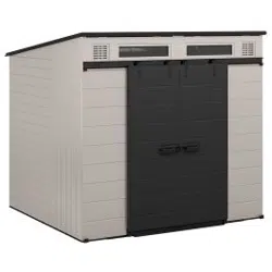
BMS8781T
Modernist
® 8 x 7
ASSEMBLY
INSTRUCTIONS
Tools
Required
7/1
6"
INCLUDED
IN
KIT
Easy
Bolt
Driver
MADE
IN
THE
W
..
USA
LI
*COLOR/STYLE
MAY
VERY
BY
MODEL
NUMBER.
Scan
QR
Code
for
product
assembly
video.
C)
2025
Suncast
Corporation,
Batavia,
IL
USA
0660265A

Register
within
90
days
of
purchase
to
activate
Warranty!
Registration
is
not
required
for
products
with
a
warranty
term
of
90
days
or
less.
1.
Verify
warranty
term
of
your
product
by
visiting
www/suncast.com/warranty
(products
with
a
warranty
term
of
90
days
or
less
do
not
require
registration)
2.
Complete
registration:
fill
out the
form
and
upload
a
copy
of
your
receipt
by
visiting
https://support.suncast.com
or
scanning
the
OR
code
Have
Questions?
For
product
questions,
assembly
assistance,
replacement
parts
and
more:
ht
-
tps://support.suncast.com
Suncast
Corporation
Customer
Care
701
N.
Kirk
Road,
Batavia,
IL
60510
1-800-846-2345
1-630-381-6309

A
Before
You
Begin...
•
Consult
your
local
authorities
for
any
permits
required
to
construct
shed.
Prior
to
construction
of
your
shed,
check
with
the
local
building
code
official
to
review
any
required
permits
or
building
limitations.
• A
level
and
sturdy
foundation
is
required
before
shed
construction
can
begin.
Site
preparation
information
is
available
later
on
in
this
manual.
A
foundation
that
differs
from
the
specifications
within
this
manual
could
prevent
proper
assembly
and
may
damage
parts.
•
Read
instructions
thoroughly
prior
to
assembly.
This
kit
contains
parts
that
can
be
damaged
if
assembled
incorrectly
or
in
the
wrong
sequence.
•
Please
follow
instructions.
Suncast
is
not
responsible
for
replacing
parts
lost
or
damaged
due
to
incorrect
assembly.
•
Assistance
is
required
during
entire
assembly.
Indicates
at
least
1
additional
adult
is
needed
to
complete
this
step.
Indicates
caution
is
recommended
when
using
a
power
drill.
IMPORTANT
COMPLETE
SITE
PREPARATION
AND
FOUNDATION
CONSTRUCTION
BEFORE
UNPACKING
ALL
PARTS.
OPEN
ALL
BOXES
FIRST
AND
NEATLY
LAYOUT
PARTS.
SMALL
PARTS
MAY
BE
CONTAINED
IN
EACH
BOX.
PLEASE
REFERENCE
THE
PARTS
LIST
WITHIN
THIS
MANUAL
TO
VERIFY
ALL
PARTS
ARE
PRESENT.
A
Caution
•
Power
tools
can
apply
excessive
torque
resulting
in
damage
to
the
product.
If
you
choose
to
use
a
power
drill
to
assemble
the
product,
Suncast
recommends
using
a
variable
speed,
cordless
drill
with
a
variable
clutch set
at
the
lowest
setting.
A #
2
Phillips
driver
bit
is
compatible
with
the
hardware
provided.
Suncast
makes
no
guarantee
that
following
this
recommendation
will
prevent
damage
to
the
product.
Damage
to
parts
due
to
over-
torque
are not
covered
under
Suncast's
limited-
warranty.
•
Proper
site
preparation
required.
•
Shed
not
intended
for
storage
of
flammable,
caustic
or
corrosive
materials.
•
Shed
not
intended
for
habitation
or
for
use
by
children.
•
DO
NOT
stand,
sit,
or
store
items
on
storage
shed
roof.
•
Repair
or
replace
broken
parts
immediately.
•
DO
NOT
place
near
objects
that
are
hot
or
can
become
hot.
•
Heavy
articles
should
not
be
leaned
against
the
walls,
as
this
may
cause
panel
distortion
and
permanent
damage.
•
Suncast
is
not responsible
for
damage
caused
by weather
or
misuse.
•
This
kit
contains
parts
with
sharp
edges.
Please
be
careful
when
handling,
use
of
work
gloves
is
recommended.
•
WHEN
DRILLING
THROUGH
METAL,
beware
of
burrs,
shavings
and
other
sharp
edges.
Safety
glasses
are
strongly
recommended.
•
DO
NOT
place
in
areas
near
highly
reflective
surfaces (
Note:
Low-
E
windows
are
more
reflective
than
standard
windows
and
may
affect
the
longevity
of
the
product).
•
Product
is
water
resistant
and
not
waterproof.
Locate
unit
away
from
gutter
and
down
spouts
for
optimal
performance.
3

A
Shed
Care
and
Maintenance
•
At
regular
intervals,
inspect
your
shed
to
make
sure
that
assembly
integrity
has
been
maintained.
•
Periodically
check
that
the
location
you
have
chosen
to set
your
shed
is
still
level.
•
Keep
roof
clean
of
snow
and
leaves.
•
To
maintain
the
look
of
your
product,
we
recommend
cleaning
it
at
regular
intervals
with
mild
soap
and
water.
DO
NOT
use
bleach,
ammonia
or
other
caustic
cleaners,
and
DO
NOT
use
stiff
bristle
brushes.
Failure
to
perform
cleaning
at
regular
intervals
could
result
in
permanent
staining
of
the
plastic.
This
type
of
damage
is
not
covered
under
warranty.
A
Assembly
Day
Tips
•
Do
not
attempt
to
assemble
on
a
day
with
strong
winds.
•
Set
aside
appropriate
amount
of
time
to
completely
assemble
shed.
An
incomplete
shed
assembly
may
pose
a
safety
hazard.
•
Make
sure
you
have
assistance
nearby
to
lift
and
secure
parts
in
place.
•
Once
roof
is
assembled,
a
flashlight
may
be
of
use
when
assembling
smaller
components
inside
shed.
•
Do
not
use
a
torque
wrench
or
hand
drill
to
tighten
Easy
bolts.
Use
provided
Easy
Bolt
Driver
ONLY.
•
Suncast
provides
extra
hardware
for
small
fasteners
for
customer
convenience.
In
some
cases,
there
will
be
extra
small
fasteners
once
the
assembly
is
complete.
Note:
This
product
contains
parts
that
are
used
in
different
orientations
to
construct
the
shed.
Please
take
note
of
the
orientation
of the parts
shown
throughout
this
instruction
manual.
Failure
to
follow
instructions
could
result
in
damage
to
parts.
Suncast
is
not
responsible
for
replacing
parts
lost
or
damaged
due
to
incorrect
assembly
4

Parts -
Panels
IMPORTANT
COMPLETE
SITE
PREPARATION
AND
FOUNDATION
CONSTRUCTION
BEFORE
UNPACKING
ALL
PARTS.
OPEN
ALL
BOXES
FIRST
AND
NEATLY
LAYOUT
PARTS.
SMALL
PARTS
MAY
BE
CONTAINED
IN
EACH
BOX.
PLEASE
REFERENCE
THE
PARTS
LIST
WITHIN
THIS
MANUAL
TO
VERIFY
ALL
PARTS
ARE
PRESENT.
o
OB00903XX
Left
Front
Side
o
o
OB00870XX
Left
Middle
Side
OB01055XX
Left
Front
Header*
OB00917XX
Left
Front
o
OB00868V
Left
Back
Side
OB00918XX
Left
Door
OB00919XX
Right
Door
OB00916XX
Right
Front
OB00930XX OB00931XX
Left
Floor
Right
Floor
*Indicates
threaded
inserts
pre-
assembled
in
this
component.
For
customer
convenience
spare
threaded
inserts
are
provided
if
needed
in
hardware
bag #
0671370.
OB01054XX
Roof*
x2
o
OB01059XX
Right
Back*
OB00922XX
Right
Middle
Side
OB00914XX
Right
Front
Side
OB00876XX
Right
Back
Side
5

Parts -
Steel
o
o
o
o
o
o
o
o
o
o
o
o
o
o
o
o
o
o
o
o
o
à é à
1MRG04005A 1MRG04005A 1MRG05006A
OMR011002
68.5"
Side
Adapter
68.5"
Side
Adapter
82.94"
Truss
Leg
47.5"
Door
Track
x4
x2 x3 x2
Door
Kit:
0860132
6

6
6
o
o
o
o
o
o
o
o
o
o
j
ei)
1MRG01024
1MRG01025
1MRG02025
1MRG02028
55.14"
Ridge
Beam
39"
Ridge
Beam
82"
Header
Beam
87"
Header
Beam
x2
0511027
53"
Gutter
0511029
48"
Gutter
7
Gutter
Kit:
0464925

Parts -
Components
Parts
Box:
0465108
OMP000047
Door
Guide
Bracket
x4
010272210
Modern
Handle
x2
OMP000065
Barn
Door
Latch
OMP000066
Barn
Door
Catch
Plate
BB
OMP000048
Door
Hanger
Bracket
x4
éi)
1
MRG04004
13.5"
Side
Adapter
1MRG10001
12"
Joiner
0102726P9
Door
Wheel
x4
1
MPG00023A
Support
Bracket
x4
eit/
0441049
Window
Gasket
0441037
Door
Window
x2
0480589A —
Easy
Driver &
Slide
o
010256307
Easy
Bolt
x32
BBB
010272110
Roof
Bracket
x8
Easy
Driver*
0102552XX
Cord
Slide
8

Master
Hardware
Bag -
0470002A
Master
Hardware
Bag:
0470002A
0480377 — #
10
Screw
(x2
bags)
0630821
#10
x .
625"
Screw
x312
(156
per
bag )
0671319 —
Barn Door
0632130
#10
x
1.75"
Screw
0631252
#10
x
1"
Screw
x3
0510987
Nylon
Spacer
0631733A
.25"
Flat
Washer
x4
0671320 —
Hanger
0671318 —
Steel
0671336 —
Track
0631456
1/4-20
x
1.5"
Carriage
Bolt
x8
0631732
.25-20
Lock
Nut
x8
0631733A
.25"
Flat
Washer
0671321 —
Sliding
Door
0632496 0510987
1/4-20
x
1.25"
Nylon
Spacer
Carriage
Bolt
x4
x12
0631148
.25-20
Nylon
Lock
Nut
x12
0632504
.25-20
x
2"
Hex
Bolt
x15
0631148
.25-20
Nylon
Lock-
Nut
x15
0671368-
Insert
Bolts
0631115
.25-20
x
1"
Hex
Bolt
x2
0631011
.375"
Flat
Washer
x4
0631733A
.25"
Flat
Washer
x12
0632449
#8-32
x .
5"
Bolt
x35
(1)
0631148
.25-20
Lock
Nut
x2
0102748P9
Door
Bumper
x2
Hardware
shown
at
actual
size (*
Unless
otherwise
noted.)
Extra
hardware
provided.
Not
all
are
used.
9

Parts:
Accessories
Please
note,
not
all
shed
models
include
accessories.
Please
reference
the
UPC
located
on
the
shed
packaging
to
determine
your
shed's
model
number.
II
1
0
44670
012
2 6
Im>
BMS87XX
BMS8781T
0102785P9
Tool
Hanger
x4
Easy
bolts
required
for
mounting
accessories
included
with
shed
hardware.
To view
full
range
of
accessories
available
for
your
shed,
please
visit
our
website
at
www.suncast.conn.
10

Site
Preparation
and
Platform
Construction
Materials
NOT
supplied
with
Shed
Kit
Important:
•
Site
preparation
is
required
for
this
shed.
Placing
the
shed on
a
properly
constructed,
square,
flat,
smooth
and
level
foundation,
as
described
below,
is
required.
Without
a
properly
constructed
foundation,
settling
will
eventually
occur,
causing
distortion
and
damage
to
the
shed.
Suncast
is
not
responsible
for
replacing
parts
damaged
or
property
lost
due
to incorrect
foundation
construction
or
improper
assembly.
Warranty
requires
a
properly
constructed
foundation
to
which
the
shed
must
be
anchored
as
instructed
below.
•
Complete
the
site
preparation
and
foundation
construction
before
unpacking
parts
and
beginning
assembly.
For
tips
on
site
preparation,
go
to
www.suncast.com,
consult
retailer,
or
local
code.
Site
Preparation
1.
Consult
your
local
authorities
for
building
codes
and
covenants
before
beginning
foundation
or
erecting
shed.
2.
Before
any
digging,
check
with
local
utilities
to
determine
location
of
buried
cables,
pipes,
etc.
3.
Decide
which
type
of
foundation
is
most
suitable
for
your
installation.
The
foundation
surface
must be
square,
flat,
smooth
and
level.
Follow
the
below
guidelines
for
foundation
options.
4.
Complete
the
foundation
preparations
as
follows:
• A
vapor
barrier
may
be
applied
over
the
foundation
to
prevent
excessive
condensation
in
the
shed.
Follow
local
building
codes
for
a
proper
vapor
barrier.
•
The
ground
should
slope
away
from
the
foundation area
to
provide
drainage.
•
Placing
the
shed
on
surfaces
made
of
materials
such
as
patio
blocks
or
pavers
is
not
acceptable
for
long-term
support
structure
or
smooth
surface.
Use
of
these
will
void
the
warranty.
Concrete
Slab
•
Construct
a
slab
of
at
least
4"
thickness.
•
The
use
of
reinforcement
bar
is
recommended.
•
For
foundations
larger
than
specified
below, the
shed
must
rest
on
a
continuous,
level
portion
of
the
concrete
slab.
Shed
Footprint
(for
both
concrete
and
wood)
"
Dimensions
shown
are
minimal
for
proper
fit
of
the
shed.
Wood
Platform
•
Use
exterior
grade
wood.
•
Set
the
wood
platform
on
deck
footing
blocks
or
full
footing.
Anchoring
the
Floor
Panels
to
the
Foundation
is
required
after
shed assembly
is
complete.
•
Shed
floor
panels
include
wall
anchor
locations
as
well
as
flattened
areas
where
anchors
or
lag
screws
are
to
be
secured.
These
flat
areas
must
be
drilled
through
prior
to
securing
the
floor
panels
to
the
foundation.
•
The
shed
must
be
secured
to
a
continuous
concrete
slab
using
3/8"
masonry
anchors
with
1"
washers (
hardware
not
included).
8
masonry
anchors
are
required.
Floor
anchor
section
example
•
The
shed
must
be
secured
to
a
wood
platform
using
1/4"-3/8"
x
3"
lag
screws
with
1"
washers (
hardware
not
included).
8
lag
screws
are
required.
Note:
Shed
floor
fastening
locations
are
designed
to
align
with
the
under-
structure
layout.
Be
sure
the
front
of
the
floor
panels
are
oriented
correctly
on
the
platform
to
ensure
lag
bolts
engage
with
the
under-
structure.
11

Site
Preparation
and
Platform
Construction (
continued)
Materials
NOT
supplied
with
Shed
Kit
Wood
platform
critical
spacing
•
Check
all
critical
spacing
measurements
carefully.
98"
4
1514
,
4
12"
1
1!
4
12"
89
"
4
12"
4
12"
ir
4
12"
4
13
3/4 "
*
-.1-2
3/4"
46
3/4"
Front
I
51/2u
45
3/4"
3"
Wood
platform platform
materials
list
Item
Qty
Size
a
1
48"
x
89"
x .
75"
b
2
25"
x
89"
x .
75"
c 8
2"
x
6"
x
12.25"
d
2
2"
x
6"
x
89"
e 8
2"
x
6"
x
95"
•
Please
note,
2 x 6
dimensional
lumber
is
actually
1/2"
smaller
than
noted
sizes.
Dimensions
given
presume
standard
1.5"
x
5.5"
actual
size
lumber.
Lumber
dimensions
can
vary.
Check
lumber
dimensions
before
cutting
and
make
appropriate
adjustments
to
achieve
given
dimensions.
Cut
sizes
are
actual
size.
12

IMPORTANT:
If
you
choose
to
use
a
power
drill
to
assemble
the
product,
refer
to
caution
statements
for
power
drill
guidelines.
Damage
to
parts
due
to
over-
torque
are
not
covered
under
Suncast's
limited-
warranty.
This item
uses
self-
tapping
screws
in
some
areas.
There
are
no
pre-
drilled
holes.
Some
pressure
may
be
needed
when
starting
to
drive
the screw.
Once
the
screw
pierces
the
plastic
it
will
drive
easier.
Pre-
Assembly -
Floor
Guides
Required
Hardware/
Steel
Kits
0480377
(S)
x12
Stand
the
right
floor
(
B)
horizontal.
From
the
bottom
of
the
panel,
install
2
door
guide
brackets
(
R)
and
secure
with
3
screws
(
S)
each
as
shown.
Repeat
for
left
floor
(
A).
Barn
Required
Hardware/
Steel
Kits
(V)
x2
(FF)
x2
From
the
inside
of
the
left
door (
L)
install
2
washers
(
V)
and
2
screws
(
FF).
From
the
outside
of
the
door
place
door
catch
plate
(
W)
and
1
door
handle
(
X)
through
the
previously
installed
screws
(
FF).
Tighten
securely.
(X)
x1
13

(V)
x2
IL
(YY)
x1 (
X)
x1
(FF)
x1
(
AA)
x1
From
the
inside
of
the
right
door
(
D)
install
washer
(
V),
nylon
spacer
(
YY),
and
screw
(
Z)
through
the
slotted
hole.
Install
1
washer
(
V)
and
1
screw
(
FF)
in
the
remaining
hole.
From
the
outside
of
the
door
(
D),
place
door
latch
(
AA)
and
1
door
handle
(
X)
through
the
previously
installed
screws
as
shown.
Proceed
to
thread
screws
(
FF,Z)
into
the
handle
(
X).
Do
not
overtighten,
handle should
move
freely.
Pre-
Assembly -
Door
Hangers
Required
Hardware/
Steel
Kits
Hanger
7/16"
(CC)
x4
Orient
1
door
hanger
bracket
(
BB)
as
shown.
Place
1
bolt
(
CC)
through
top
hole
and
install
the
following
parts
in
order:
1
washer
(
DD),
1
nylon
spacer
(YY),
1
door
track
wheel
(
EE),
and
1
larger
washer
(
V)
secure
with
1
lock
nut
(
GG).
IMPORTANT:
Refer
to
images
provided
for
proper
orientation.
Do
not
overtighten,
wheel
should
spin
freely.
Repeat
for
remaining
3
door
hanger
assemblies.
(DD)
x4
(V)
x4
(GG)
x4
(BB)
x4
(EE)
x4
To
door
Side
View
14

(HH)
o
7/16"
(GG)
x8
(CC)
x8
(V)
x8
NOTE:
The
2
holes
in
both
door
panel
pockets
may
need
to
be
pierced
prior
to
inserting
bolts.
Tilt
the
left
door
(
L)
upright.
Nest
door
hanger
assembly
into
the
pocket
of
left
door
as
shown.
Secure
with
2
bolts
(
CC),
2
washers
(
V),
and
2
locknuts
(
GG).
Repeat
to
install
second
door
hanger
assembly on
left
door
and
remaining
door
assemblies
on
right
door
(
D).
Pre-
Assembly -
Windows
Required
Hardware/
Steel
Kits
0480377
j
Place
left
header
(
Q)
with
smooth
side
facing
down
on
a
flat
surface.
Starting
at
the
top-
center,
working
clockwise
press
1
gasket
(
HH)
into
channel
as
shown.
Trim
any
excess
gasket
with
scissors.
Repeat
for
right
header
(
M).
NOTE:
Do
not
stretch
the
gasket
when
installing.
Press
firmly
downward
and
slightly
backward
while
running
the
gasket
around
the
gasket
channel.
15

(S)
x22
(
JJ)
x2
NOTE:
Remove
the
protective
film
from both
sides
of
the
window
(
JJ)
prior
to
installation.
Starting
with
left
header
(
Q)
install
window
(
JJ)
as
shown
and
secure
with
11
screws
(
S).
Do
not
overtighten.
Repeat
for
right
header (
M).
y
xl
1
î
o
Pre-
Assembly -
Header
Required
Hardware/
Steel
Kits
0480377
Track
(S)
x4
Place
right
front
header
(
M)
into slot
on
left
front
header
(
Q) as
shown
and
secure
with
4
screws
(
S).
0x4
IMPORTANT:
Make
sure
the
bottom
edges
of
both
headers
are
flush.
Do
not
overtighten.
sizez
..2>
16

Top
of
header
Top
of
header
e
w=k
(S)
x1
2
j
Place
2
header
beams (
87",LL)
in
channels
of
headers (
M,Q).
Secure
header
beams (
LL)
with
12
screws (
S).
e
IMPORTANT:
Pay
particular
attention
to
the
screw
locations
indicated
in
the
images.
Install
screws
into
exact
locations
as
shown (
not
all
screw
holes
are
used
at
this
point
in
the
assembly).
The
slotted
holes
will
be
used
on
the
top
of
the
header
beam,
while
the
circular
holes
will
be
used on
the
bottom
of
the
header
beam.
e
NOTE:
A
screwdriver
may
be
needed
to
pierce
the
holes
on
header
prior
to
installing
the
carriage
bolts.
Carefully,
flip
over
header
assembly (
Q,M)
so
the
smooth
side
is
facing
up.
Nest
2
door
tracks (
MM)
into
pockets
making
sure
that
door
tracks
are
aligned
at
center.
Secure
with
8
carriage
bolts (
NN)
and
8
nuts (
00).
Leave
bolts
loose
as
this
time.
17

Pre-
Assembly -
Side
Adapter
Required
Hardware/
Steel
Kits
0480377
(S)
x2
Carefully
flip
over
header
assembly
(
M,Q)
so
smooth
side
is
facing
down.
Place
side
adapter
(
13.5",PP)
as
shown.
Secure
the
top
of
the
side
adapter
(PP)
with
2
screws
(
S).
IMPORTANT:
Orientation
of
side
adapter (
PP)
is
critical.
Top
of
header
(S)
x4
From
the
bottom
of
the
header
assembly
(
M,Q)
slide
the
gutter
(
48",T)
into
position.
Using
4
screws,
secure
gutter
(
T)
at
the
locations
indicated.
IMPORTANT:
The
two
middle
screw
locations
will
also
secure
the
bottom
of
side
adapter (
PP).
Top
of
header
11
â
11
t
DTF'"iTWn
,
• ,
De'
• •
e
e e
e e
OGG 000
Ox4
-.
iveL
o
o 0
000 GOO
$
18

co
(V)
xl
Attach
the
cord
slide
(
WW)
to
the
left
back
panel
(
I)
using
1
screw
(
S)
and
washer
(
V).
NOTE:
Do
not
overtighten
the
screw.
The
cord
slide
should
easily
slide
back
and
forth
without
much
resistance.
o
Slide
the
left
and
right
floors
(
A,B)
together.
Secure
with
7
screws
(
S).
19

Insert
the
bottom
tabs
of
left
front
(
E)
into
the
slots
of
the
left
floor
(
A)
as
shown.
Slide
the
left
front
towards
the
center
of
the
floor
until
it
locks
into
place.
[hmi
Align
the
side
tabs
of
left
front
side
(
F)
with
the
slots
on
left
front
(
E).
Slide
left
front
side
(
F)
down
to
engage
tabs.
Continue
to
press
firmly
until
bottom
tabs
snap
into
left
floor
(
A)
as
shown.
20

(ZZ)
x5
[kmi
}
Insert
the
bottom
tabs
of
left
middle
side
(
G)
into
the
slots
of
the
left
floor
(
A)
as
shown.
Slide
the
left
middle
side
(
G)
towards
the
front
of
the
floor
until
it
locks
into
place.
Secure
the
left
middle
side
(
G)
to
the
left
front
side
(F)
using
5
easy
bolts (
ZZ).
Tighten
securely (
3-4
clicks).
21

[kmi,
Insert
the
bottom
tabs
of
the
left
back
(I)
with
the
slots
of
the
left
floor
(
A)
as
shown.
Slide
the
left
back
(
I)
towards
the
corner
of
the
floor (
as
indicated
by
the
arrow)
until
it
locks
into
place.
[kmi
Align
the
side
tabs
of
the
left
back
side
(
H)
with
the
slots
on
the
left
back
(
I).
Slide
left
back
side
(
H)
down
to
engage
tabs.
Continue
to
press
firmly
until
bottom
tabs
snap
into
left
floor
(
A)
as
shown.
22

(ZZ)
x5
Secure
the
left
back
side
(
H)
to
the
left
middle
side
(
G)
using
5
easy
bolts (
ZZ).
Tighten
securely (
3-4
clicks).
Insert
the
bottom
tabs
of
right
back
(J)
into
the
slots
of
the
right
floor
(
B)
as
shown.
Slide
the
right
back
(
J)
towards
the
center
of
the
floor
until
it
locks
into
place.
23

(ZZ)
x5
Secure
the
left
back
(
I)
to
the
right
back
(
J)
using
5
easy
bolts (
ZZ).
Tighten
securely (
3-4
clicks).
[Ami
Align
the
side
tabs
of
the
right
back
side
(
K)
with
the
slots
on
the
right
back
(
J).
Slide
right
back
side
(
K)
down
to
engage
tabs.
Continue
to
press
firmly
until
bottom
tabs
snap
into
right
floor
(B)
as
shown.
24

[kmi
}
Insert
the
bottom
tabs
of
right
middle
side
(
Y)
into
the
slots
of
the
right
floor (
B)
as
shown.
Slide
the
right
middle
side
(
Y)
towards
the
corner
of
the
floor
(as
indicated
by
the
arrow)
until
it
locks
into
place.
(ZZ)
x5
Secure
the
right
back
side (
K)
to
the
right
middle
side
(
Y)
using
5
easy
bolts (
ZZ).
Tighten
securely (
3-4
clicks).
25

Insert
the
bottom
tabs
of
right
front
(
C)
into
the
slots
of
the
right
floor
(
B)
as
shown.
Slide
the
right
front
(
C)
towards
the
corner
of
the
floor (
as
indicated
by
the
arrow)
until
it
locks
into
place.
LA-i1
Align
the
side
tabs
of
the
right
front
side
(
N)
with
the
slots
on
the
right
front
(
C).
Slide
right
front
side
(
N)
down
to
engage
tabs.
Continue
to
press
firmly
until
bottom
tabs
snap
into
right
floor
(
B)
as
shown.
26

(ZZ
x
5)
Secure
the
right
middle
side
(Y)
to
the
right
front
side
(
N)
using
5
easy
bolts (
ZZ).
Tighten
securely (
3-4
clicks).
(S)
x1
0
Place
header
assembly
(
M,Q)
over
the
left
front
(
E)
and
right
front
(
C)
panels.
Align
side
slots
on
header
assembly
with
tabs
on
front
sides
panels.
Once
aligned
slide
header
down
to
engage
into
slots
Secure
header
assembly
(
M,Q)
with
10
screws
(
S).
27

(S)
x4
1
11
1
11
I
11 11
(S)
x2
[c?
• .]
Position
header
beam (
82",AAA)
across
the
left
and
right
il back
panels (
IA
as
shown.
Secure
with
4
screws (
S).
Secure
support
bracket (
VV)
to
the
back
header
beam (
AAA)
using
2
screws (
S).
IMPORTANT:
Orientation
of
support
bracket (
W)
is
critical.
e
o
28

(S)
x32
IMPORTANT:
Orientation
is
critical.
[
• I
Secure
2
side
adapters
(
68.5",CCC)
to
the
left
and
right
back
k e X
panels
(
IA
using
16
screws
(
S)
each.
Reference
image below
for
adapter
locations.
29

(S)
x32
IMPORTANT:
Orientation
is
critical.
(S)
x32
IMPORTANT:
Orientation
is
critical.
[ •.....
1
•
Secure
1
side
adapter
each
(
68.5",CCC)
to
the
left
middle
F
111111,
side
(
G)
and
right
middle
side
(
Y)
using
16 screws
(
S)
each.
%
Reference
image below
for
locations.
[
•......„ •
Secure
1
side
adapter
each
(
68.5",CCC)
to
the
right
and
left
pi
ex
fR
ro
en
fe
trpea
bo
ne
els
im
(C
ag
,E
e)bues
lo
in
wg f1o6r
(
S)
each.
30

(GG)
x2
(S)
x6
(W)
x3
o
çI
cure
ridge
beams
to
joiner
using
2
bolts
(
TT)
and
2
nuts
(
GG).
Slide
39"
ridge
beam
(
QQ)
onto
1
end
of
joiner
(
12",SS).
Slide
55.14"
ridge
beam
(
RR)
onto
remaining
end
of
joiner
(
SS).
Se-
(TT)
x2
Tighten
securely.
4-1
Using
2
screws
each
(
S),
secure
3
support
brackets
(
VV)
to
ridge
beam
assembly
(
QQ,RR)
at
the
locations
indicated.
e,
IMPORTANT:
Orientation
of
support
brackets
are
critical.
31

(TT)
x2
NOTE:
The
support
brackets
(
VV)
should
face
the
front
of
the
shed.
(TT)
x9
Place
3
truss
legs
(
82.94",EEE),
across
the
top
of
the
shed
so
that
they
align
with
the
side
adapters
and
ridge
beam
assembly
as
shown.
Secure
using
one
bolt
(
TT)
and
nut
(GG)
at
each
joining
location.
Leave
bolts
loose
at
this
time.
(GG)
x2
(GG)
x9
Position
the
ridge
beam
assembly,
across
the
right
and
left
side
adapters (
CCC)
as
shown.
Secure
using
1
bolt
(
TT)
and
nut
(
GG)
on
each
end.
Leave
bolts
loose
at
this
time.
IMPORTANT:
Orientation
of
the
truss legs
(EEE)
is
critical.
Be
sure
to
orient
the
truss
legs
with
the
ends
having
two
holes (**)
positioned
toward
the
front
of
the
shed.
32

Identify
the
5
slots
on
1
roof
panel (
P),
and
the
5
tabs
on
side
panels (
N,Y,K).
Lay
roof
panel
over
the
5
tabs
on
the
side
panels (
N,Y,K)
as
indicated,
then
line
up
with
the
tabs
on
the
right
side
of
the
shed.
IMPORTANT:
The
wide
band
of
the
roof
panel
faces
the
front
of
the
shed.
)
e"
ee
Once
1
roof (
P)
is
in
position,
from
the
outside
of
the
shed
have
a
person
hold
the
roof
panel
in
place
while
a
second
person
slides
the
roof
towards
the
back
of
the
shed
until
the
roof
is
fully
engaged.
IMPORTANT:
The
roof
is
fully
locked
in
position
when
the
ridge
of
the
roof
sits
over
the
top
of
the
back
panel.
Check
the
slot
locations
on
the
roof to
ensure
they
have
fully
engaged
with
the
tabs
before
proceeding.

Repeat
steps
40-41
to
install
the
remaining
roof
panel (
P)
over
the
left
side
of
the
shed.
(S)
x10
*
moi
•
Secure
roof
panels (
P)
to
the
left
and
right
back
panels
(
J,I)
paix
using
5
screws
(
S)
each.
[
IMPORTANT:
With
the
help
of
another
person,
pull
down
slightly
on
outer
roof
panel
edges
while
inserting
screws
ij
aaaaa
a a
aa
aa
aaaaa =
9 a a
=D =
Da
a a a
a =
A a a a a a
a a
ia
a a
la
a a
la =
9 a a a a a
aa
a a
P=9,a9
a
0=
a a
aa
aa
aaa
a a a a
a a
aaaa
aaa
a a a a a
,9
a
aa
a =
0 a a
1=6
Pi2e
aa
n a
a .
00= =
n a a
= = =
à =
9 =
d =
9 =
9 = =
0 =
9 =
d
aaa
a a
Em
a a
aa
a a
a a a a
aaaa
ca
a a e
a a
aaaa
a a
Qam
a a = D a a
a a a
aaa
a =
9 a a a =
9 =
D a
a = D a a = 0 a E
a =
D a
a =
D
aa =
Da
a a
a =
D a a a a
aa
a E 0 a = D
a a = 0 a
a =
a a
I=6
e,P5
eB
aa
e19 e19
a
ab
rge
, a a
a .
fz
,
ee.
c
I
34

(S)
x10
•......, •
Secure
roof
panels
(
P)
to
the
header
assembly
(
M,Q)
using
5
p
screws
(
S)
each.
[
IMPORTANT:
With
the
help
of
another
person,
pull
down
slightly
on
outer
roof
panel
edges
while
inserting
screws.
•....... •
Secure
the
3
truss
legs
(
EEE)
to
the
roof
panels
(
P)
at
the
pleA
locations
indicated
using
16
screws
(
S)
each.
[

(UU)
x16
(BBB)
x4
(UU)
x16
(BBB)
x4
At
the
locations
indicated,
secure
4
roof
brackets
(
BBB)
to
the
top
of
the
front
headers
(M,Q)
and
roof
panels
(
P)
using
16
bolts (
UU).
At
the
locations
indicated,
secure
4
roof
brackets
(
BBB)
to
the
top
of
the
left
and
right
backs
(
I,J)
and
roof
panels
(
P)
using
16
bolts
(UU).
eb
v=i
e,a,c3
aale.klie .
a=o
oa
,
g=w .
. .
grl.o
H
grimp
11=o
g.° .
oa_.1=v
1=a
lmr
-
oso .
._
1,
y
wona.
am,
. d
et
HO
H H H H
Ht
H
la
0
4=1
.4 0 0
la
0 a 0 0
la
Et
0 0 0
a 0 0 a 0 0 a
Et
a
Et
0 0 0 a
la
0 a 0 0 a
la
0 0 0 0 0
. H
la
0 0 0 0
Et
' 'a
r0
E
71
=
7,
Et
la=o
%
la
a 0 0 0 0 a
.1E7t
El
0 a
ED
0 0 a 0 0 a 0 0
Et
a 0
0
Et
a
El
0
00
0 a 0 0
la
0 0
Et
0
a 0 0
alla
0
El
0
Er
0
Et
0
CP
y
Et
Et Et
a
la
la
E , a 0 0
Et
a a
0
...
a .= ,
00
la El
a
la
0 a a a
a__.
a
00
00_
.=.
0 „
ntLas
a
at
.,..
ea
0 0 a
la
fa
0 a
0
la
0 0 0
_.
' 7
0
He
0
10
0 a
ala
a 0 0
EU&
a a
Era=
36

• •
With
the
gutter
(
53",U)
orientated
as
shown,
slide
gutter
(
U)
in-between
the
left
and
right
headers
d (
Q,M)
and
the
previously
installed
door
track
(
MM).
Once
gutter
(
U)
is
in
position,
tighten
the
8
bolts
(NN)
and
nuts
(
00).
IMPORTANT:
Be
sure the
top
edge
of
the
gutter (
U)
is
making
contact
with
the
previously
installed
carriage
bolts (
NN)
before
securing.
37

It •
From
the
left
side
of
the
shed
align
the
left
door
(
L)
with
the
door
track
(
MM)
and
door
guides
(
R)
as
p I X
shown.
Slide
door
towards
the
center
of
the
shed
to
engage.
[
.)
Repeat
process
from
the
right
side
of
the
shed
to
install
the
right
door
(
D).
(JJJ)
x2
(GG)
x2
Install
1
bumper
(
HHH)
to
the
right
side
of
door
track
(
MM)
using
1
bolt
(
JJJ)
and
nut
(
GG).
Repeat
for
left
side
of
door
track.
38

Assembly -
Tool
Hanger
Accessory
Important:
Only
Use
the
Easy
Bolt
hole
in
the
hanger
when
mounting
to
shed
panels.
Installation
Align
the
hanger
with
the
desired
shed
wall
hole.
Insert
1Easy
Bolt (
ZZ).
Tighten
securely (
3-4
clicks).
NOTE:
Easy
bolts
for
included
shed
accessories
are
provided
in
Easy
Bolt
hardware
bag
within
the
parts
kit.
Please
note,
only
model
BMS8780T
includes
shed
accessories
with
the
product.
Attach
a
5/16"
lock (
not
provided)
to
door
latch
to
properly
secure
shed.
NOTE:
To
maintain
warranty
coverage,
the
product
should
be
padlocked
at
all
times
when
not
in
use.
VVVV1234567
DO
NOT
REMOVE
Patents,
www.suncast.com
This
label
located
on
the
inside
of
door
contains
information
regarding
your
product.
The
OR
code
is
a
direct
product
link
to
the
product
registration
page
on
the
Suncast
website.
The
codes
at
the
bottom
of
the
label
are
specifically
related
to
your
product.
Please
have
these
numbers
available
should
you
need
to
contact
Suncast.
39

szinclest