Maintenance and Service Guide
HP Fortis G1m 11 inch Chromebook
SUMMARY
This guide provides maintenance information about such topics as spare parts, removal and replacement of
parts, security, and backing up.

Legal information
© Copyright 2024 HP Development
Company, L.P.
AMD is a trademark of Advanced Micro
Devices, Inc. Bluetooth is a trademark owned
by its proprietor and used by HP Inc.
under license. Intel is a trademark of Intel
Corporation or its subsidiaries in the U.S.
and/or other countries. Chrome, Chrome
OS, Chromebook, and Google Drive are
trademarks of Google LLC. Windows is either
registered a trademarks or trademarks of
Microsoft Corporation in the United States
and/or other countries. USB Type-C and
USB-C are registered trademarks of USB
Implementers Forum. DisplayPort™ and the
DisplayPort™ logo are trademarks owned by
the Video Electronics Standards Association
(VESA®) in the United States and other
countries. Wi-Fi is a registered trademark of
Wi-Fi Alliance.
The information contained herein is subject
to change without notice. The only
warranties for HP products and services are
set forth in the express warranty statements
accompanying such products and services.
Nothing herein should be construed as
constituting an additional warranty. HP shall
not be liable for technical or editorial errors
or omissions contained herein.
First Edition: December 2024
Document Part Number: P21809-001
Product notice
This guide describes features that are
common to most models. Some features
may not be available on your computer.
To access the latest user guides, go to
http://www.hp.com/support, and follow the
instructions to find your product. Then select
Manuals.
Software terms
By installing, copying, downloading, or
otherwise using any software product
preinstalled on this computer, you agree
to be bound by the terms of the HP End
User License Agreement (EULA). If you
do not accept these license terms, your
sole remedy is to return the entire unused
product (hardware and software) within 14
days for a full refund subject to the refund
policy of your seller.
For any further information or to request
a full refund of the price of the computer,
please contact your seller.

Safety warning notice
Reduce the possibility of heat-related injuries or of overheating the computer by following the practices
described.
WARNING! To reduce the possibility of heat-related injuries or of overheating the computer, do not
place the computer directly on your lap or obstruct the computer air vents. Use the computer only on a
hard, flat surface. Do not allow another hard surface, such as an adjoining optional printer, or a soft
surface, such as pillows or rugs or clothing, to block airflow. Also, do not allow the AC adapter to come
into contact with the skin or a soft surface, such as pillows or rugs or clothing, during operation. The
computer and the AC adapter provided by HP comply with the user-accessible surface temperature
limits defined by applicable safety standards.
iii

Important notice about Customer Self-Repair parts
Your computer includes Customer Self-Repair parts and parts that should be accessed only by an
authorized service provider.
IMPORTANT: See Removal and replacement procedures for Customer Self-Repair parts on page 25
for details.
Accessing parts described in Removal and replacement procedures for authorized service provider
parts on page 32 can damage the computer or void your warranty.
iv Important notice about Customer Self-Repair parts

Table of contents
1 Product description............................................................................................................................................................................................................................. 1
2 Components........................................................................................................................................................................................................................................... 3
Right........................................................................................................................................................................................................................................................3
Left........................................................................................................................................................................................................................................................... 3
Display .................................................................................................................................................................................................................................................. 4
Keyboard area.................................................................................................................................................................................................................................5
Touchpad .................................................................................................................................................................................................................................6
Special keys...........................................................................................................................................................................................................................6
Bottom ...................................................................................................................................................................................................................................................7
Labels ....................................................................................................................................................................................................................................................8
3 Illustrated parts catalog ..............................................................................................................................................................................................................10
Chromebook major components....................................................................................................................................................................................10
Display assembly subcomponents................................................................................................................................................................................ 11
Miscellaneous parts.................................................................................................................................................................................................................13
4 Removal and replacement procedures preliminary requirements..............................................................................................................16
Tools required ................................................................................................................................................................................................................................16
Service considerations..........................................................................................................................................................................................................16
Plastic parts.........................................................................................................................................................................................................................16
Cables and connectors...............................................................................................................................................................................................16
Drive handling ....................................................................................................................................................................................................................16
Electrostatic discharge information..............................................................................................................................................................................17
Generating static electricity.....................................................................................................................................................................................17
Preventing electrostatic damage to equipment.......................................................................................................................................18
Personal grounding methods and equipment............................................................................................................................................18
Grounding the work area............................................................................................................................................................................................19
Recommended materials and equipment.....................................................................................................................................................19
Cleaning your computer....................................................................................................................................................................................................... 20
Enabling HP Easy Clean (select products only)........................................................................................................................................ 20
Removing dirt and debris from your computer.........................................................................................................................................20
Cleaning your computer with a disinfectant................................................................................................................................................21
Caring for wood veneer (select products only) ........................................................................................................................................ 22
Packaging and transporting guidelines..................................................................................................................................................................... 22
Accessing support information ...................................................................................................................................................................................... 22
5 Removal and replacement procedures for Customer Self-Repair parts ............................................................................................... 25
Component replacement procedures ....................................................................................................................................................................... 25
Preparation for disassembly.................................................................................................................................................................................. 25
v

Battery.................................................................................................................................................................................................................................... 25
Removing and reinstalling the same battery ..................................................................................................................................26
Installing a new battery....................................................................................................................................................................................27
6 Removal and replacement procedures for authorized service provider parts................................................................................. 32
Component replacement procedures ....................................................................................................................................................................... 32
Preparation for disassembly.................................................................................................................................................................................. 32
Bottom cover ..................................................................................................................................................................................................................... 32
Speakers...............................................................................................................................................................................................................................33
Touchpad ..............................................................................................................................................................................................................................34
WLAN module....................................................................................................................................................................................................................36
I/O boards.............................................................................................................................................................................................................................38
Heat sink ...............................................................................................................................................................................................................................40
System board ..................................................................................................................................................................................................................... 41
Display assembly............................................................................................................................................................................................................44
Top cover with keyboard............................................................................................................................................................................................. 51
7 Backing up, resetting, and recovering...............................................................................................................................................................................53
Backing up ...................................................................................................................................................................................................................................... 53
Resetting.......................................................................................................................................................................................................................................... 53
Recovering...................................................................................................................................................................................................................................... 53
Option 1: Recovering using an internet connection............................................................................................................................... 54
Option 2: Installing the Chromebook Recovery Utility.......................................................................................................................... 54
Creating recovery media .......................................................................................................................................................................................... 55
Recovering the Chrome operating system with recovery media................................................................................................ 55
Setting up your computer after a reset or recovery........................................................................................................................................55
Erasing and reformatting the recovery media .....................................................................................................................................................56
8 Statement of memory volatility..............................................................................................................................................................................................57
Current BIOS steps ...................................................................................................................................................................................................................57
Nonvolatile memory usage ................................................................................................................................................................................................ 59
Questions and answers........................................................................................................................................................................................................60
Using HP Sure Start (select products only)..............................................................................................................................................................61
9 Specifications.................................................................................................................................................................................................................................... 62
Computer specifications..................................................................................................................................................................................................... 62
29.5 cm (11.6 in) display specifications........................................................................................................................................................................63
10 Power cord set requirements ...............................................................................................................................................................................................64
Requirements for all countries ........................................................................................................................................................................................64
Requirements for specific countries and regions.............................................................................................................................................64
11 Recycling................................................................................................................................................................................................................................................67
Index................................................................................................................................................................................................................................................................68
vi

Product description1
This table provides detailed product information.
Table 1-1 Product components and their descriptions
Category Description
Product Name HP Fortis G1m 11 inch Chromebook™
Processors MediaTek MT8186 (2.05 GHz, 8 core)
Display panel 11.6 in (29.5 cm), antiglare, 250 nits
HD (1366 × 768), ultra wide viewing angle (UWVA), 50% NTSC, embedded DisplayPort™ (eDP) 1.2 without
Panel Self-Refresh (PSR), touch-on panel (TOP)
HD, UWVA, 50% NTSC, eDP 1.2 without PSR
HD, SVA, 45% NTSC, eDP without PSR
Memory Supports the following configurations:
● 8 GB, LPDDR4x-3600
● 4 GB, LPDDR4x-3766
Memory is integrated and nonconfigurable
Primary storage Embedded MultiMedia Controller (eMMC) 5.0
64 GB
32 GB
Audio Dual speakers
Video HD camera with dual-array microphone
Wireless Wireless Local Area Network (WLAN) (dual antennas)
MediaTek MT7921 Wi-Fi® 6 + Bluetooth® 5.3
Ports USB 3.1 Gen 1 Type-C® (supports up to 1920 × 1080 @ 60 Hz; left side)
USB 3.1 Gen 1 Type-A (1 right side, 1 left side)
HDMI 1.4
Audio-out (headphone)/audio-in (microphone) combo jack
Keyboard/pointing
devices
Keyboard with clickpad
Island style, spill resistant
Power requirements Battery
41 Whr, 3 cell
Long life, fast charge
Smart AC adapter (USB Type-C)
65 W, straight, USB Type-C, 1.8 m (6 ft), halogen free
Product description 1

Table 1-1 Product components and their descriptions (continued)
Category Description
45 W, nPFC, straight, USB Type-C, 1.8 m (6 ft)
Power cord
C5, conventional, power cord with sticker, 1.0 m (3.3 ft), halogen free
C5, 1.0 m (3.3 ft)
Security Dauntless Security Microcontroller
Nano lock slot
Camera privacy door
Operating system Google Chrome™
Google Chrome with Chrome Education Upgrade
Google Chrome with Chrome Enterprise Upgrade
Serviceability End user replaceable parts
Battery
AC adapter
2 Chapter 1 Product description
Components2
Your computer features top-rated components. This chapter provides details about your components,
where they are located, and how they work.
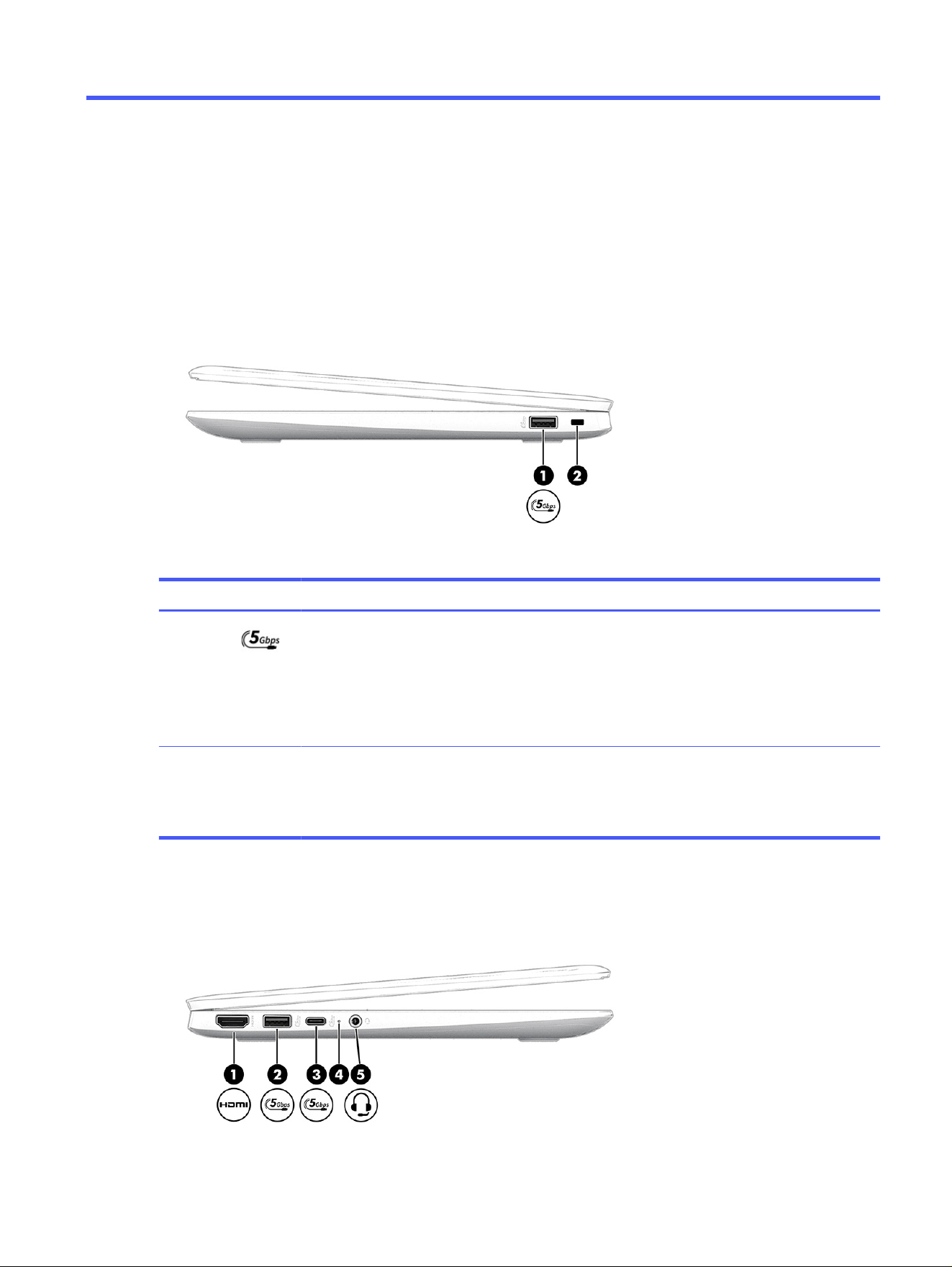
Right
Use the illustration and table to identify the components on the right side of the computer.
Table 2-1
Right-side components and their descriptions
Component Description
(1) USB 5 Gbps port Connects a USB device, provides high-speed data
transfer, and (for select products) charges small devices
(such as a smartphone) when the computer is on or in
sleep mode.
NOTE: Use a standard USB Type-A charging cable or
cable adapter (purchased separately) when charging a
small external device.
(2) Security cable slot Attaches an optional security cable to the computer.
NOTE: The security cable is designed to act as a
deterrent, but it might not prevent the computer from
being mishandled or stolen.
Left
Use the illustration and table to identify the components on the left side of the computer.
Components
3
Table 2-2 Left-side components and their descriptions
Component Description
(1) HDMI port Connects an optional video or audio device, such as a
high-definition television, any compatible digital or audio
component, or a high-speed High Definition Multimedia
Interface (HDMI) device.
(2) USB 5 Gbps port Connects a USB device, provides high-speed data
transfer, and (for select products) charges small devices
(such as a smartphone) when the computer is on or in
sleep mode.
NOTE: Use a standard USB Type-A charging cable or
cable adapter (purchased separately) when charging a
small external device.
(3) USB Type-C 5 Gbps port Connects a USB device, provides high-speed data
transfer, and (for select products) charges small devices
(such as a smartphone) when the computer is on or in
sleep mode.
NOTE: Use a standard USB Type-C charging cable or
cable adapter (purchased separately) when charging a
small external device.
(4) AC adapter and battery light ● White: The AC adapter is connected and the battery
is fully charged.
● Amber: The AC adapter is connected and the battery
is charging.
● Blinking amber: The battery level is low.
● Off: The battery is not charging.
(5) Audio-out (headphone)/Audio-in
(microphone) combo jack
Connects optional powered stereo speakers, headphones,
earbuds, a headset, or a television audio cable. Also
connects an optional headset microphone. This jack does
not support optional standalone microphones.
WARNING! To reduce the risk of personal injury, adjust
the volume before putting on headphones, earbuds, or a
headset. For additional safety information, see the
Regulatory, Safety, and Environmental Notices
.
NOTE: When a device is connected to the jack, the
computer speakers are disabled.
Display
Use the illustration and table to identify the components on the display.
4
Chapter 2 Components
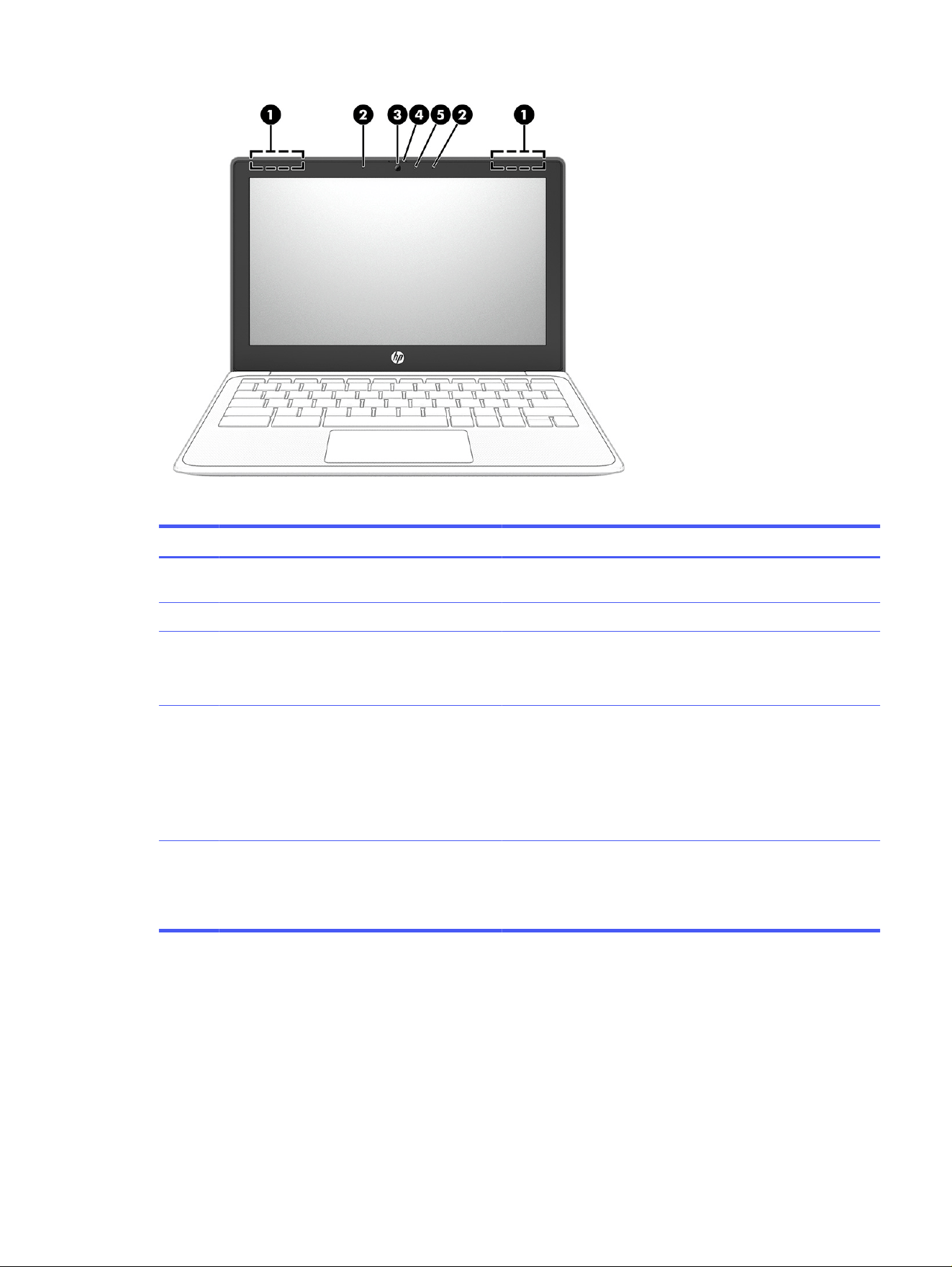
Table 2-3 Display components and their descriptions
Component Description
(1) WLAN antennas* (2) Send and receive wireless signals to communicate with wireless
local area networks (WLANs).
(2) Internal microphones (2) Record sound.
(3) Camera Allows you to video chat, record video, and record still images.
NOTE: Camera functions vary depending on the camera
hardware and software installed on your product.
(4) Camera privacy cover By default, the camera lens is uncovered, but you can slide the
camera privacy cover to block the camera's view. To use the
camera, slide the camera privacy cover in the opposite direction
to reveal the lens.
NOTE: If you have both front-facing and rear-facing cameras,
when one camera lens is revealed and ready to use, the other is
concealed.
(5) Camera light On (white): The camera is in use.
On (amber): The switch turns off the camera.
Off: The software turns off the camera.
*The antennas are not visible from the outside of the computer. For optimal transmission, keep the areas
immediately around the antennas free from obstructions.
For wireless regulatory notices, see the section of the
Regulatory, Safety, and Environmental Notices
that applies to your country or region.
Keyboard area
Keyboards can vary by language.
Keyboard area
5
Touchpad
The touchpad settings and components are described here.
Table 2-4 Touchpad component and description
Component Description
Touchpad zone Reads your finger gestures to move the pointer or activate items on the screen.
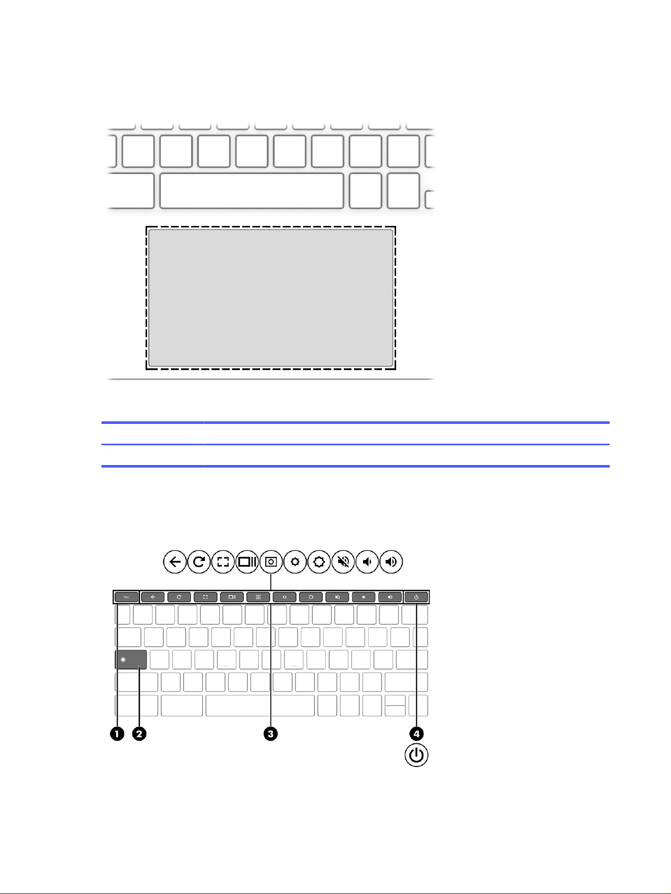
Special keys
Use the illustration and table to locate the special keys.
6
Chapter 2 Components
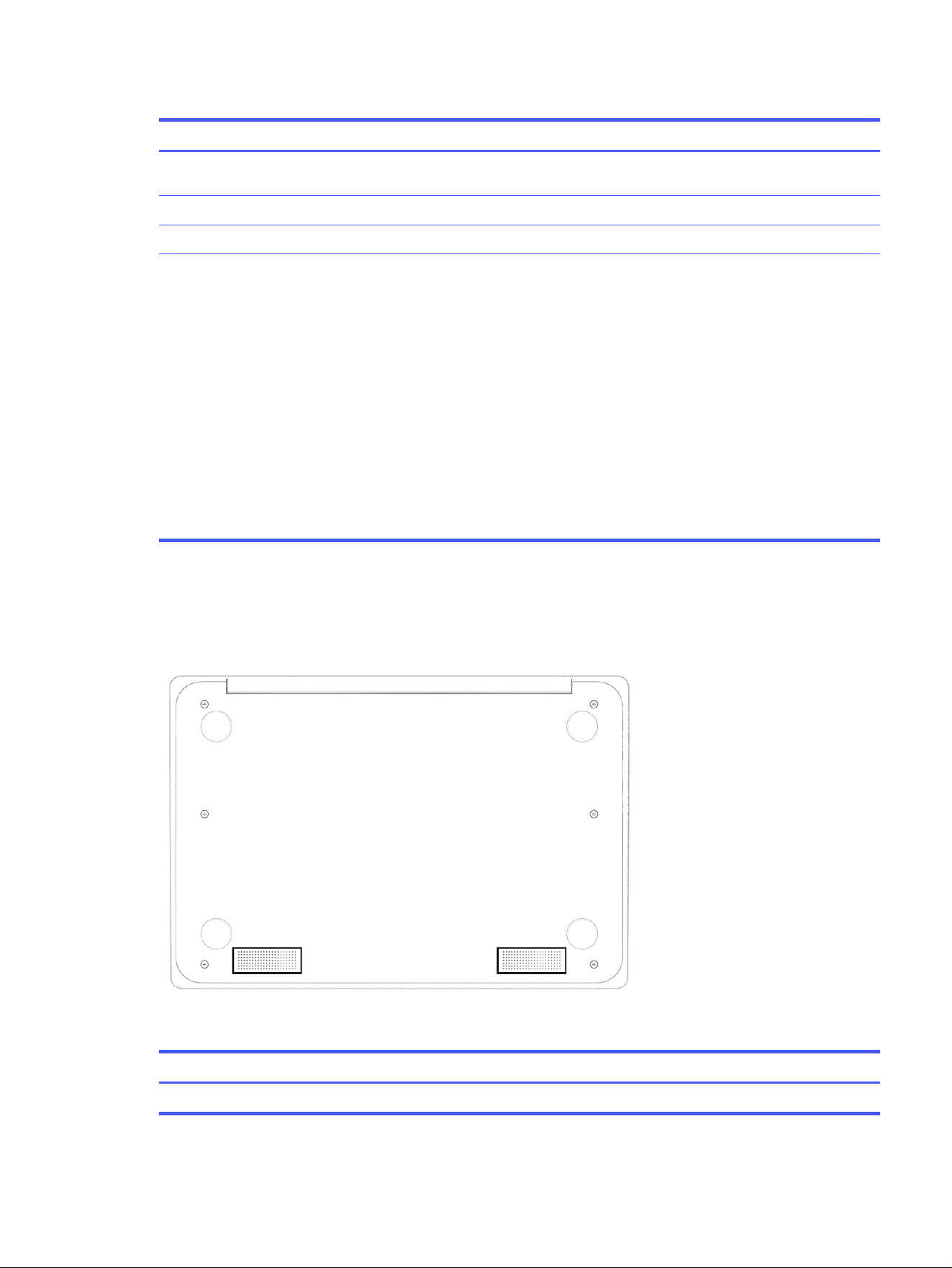
Table 2-5 Special keys and their descriptions
Component Description
(1) esc key Activates certain computer functions when pressed in
combination with other keys, such as tab or shift.
(2) Search key Runs the search function.
(3) Action keys Run frequently used system functions.
(4) Power key ● When the computer is off, press the key briefly to turn on the
computer.
● When the computer is on, press the key briefly to initiate
Sleep.
● When the computer is in the Sleep state, press the key briefly
to exit Sleep (select products only).
● When the computer is in Hibernation, press the key briefly to
exit Hibernation.
IMPORTANT: Pressing and holding down the power key results in
the loss of unsaved information.
If the computer has stopped responding and shut down
procedures are ineffective, press and hold the power key for at
least 4 seconds to turn off the computer.
Bottom
Use the illustration and table to identify the bottom components.
Table 2-6
Bottom component and description
Components Description
Speakers (2) Produce sound.
Bottom 7
Labels
The labels affixed to the computer provide information you might need when you troubleshoot system
problems or travel internationally with the computer. Labels might be in paper form or imprinted on the
product.
IMPORTANT: Check the following locations for the labels described in this section: the bottom of the
computer, inside the battery bay, under the service door, on the back of the display, or on the bottom of
a tablet kickstand.
● Service label—Provides important information to identify your computer. When contacting support,
you might be asked for the serial number, the product number, or the model number. Locate this
information before you contact support.
Your service label will resemble one of the following examples. Refer to the illustration that most
closely matches the service label on your computer.
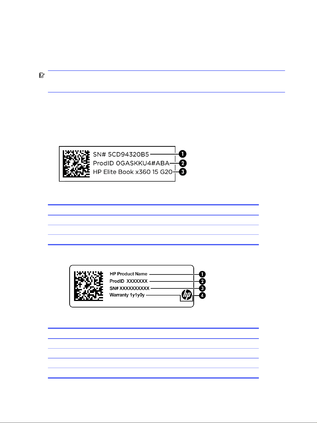
Table 2-7
Service label components
Component
(1) Serial number
(2) Product ID
(3) HP product name
Table 2-8 Service label components
Component
(1) HP product name
(2) Product ID
(3) Serial number
(4) Warranty period
8 Chapter 2 Components
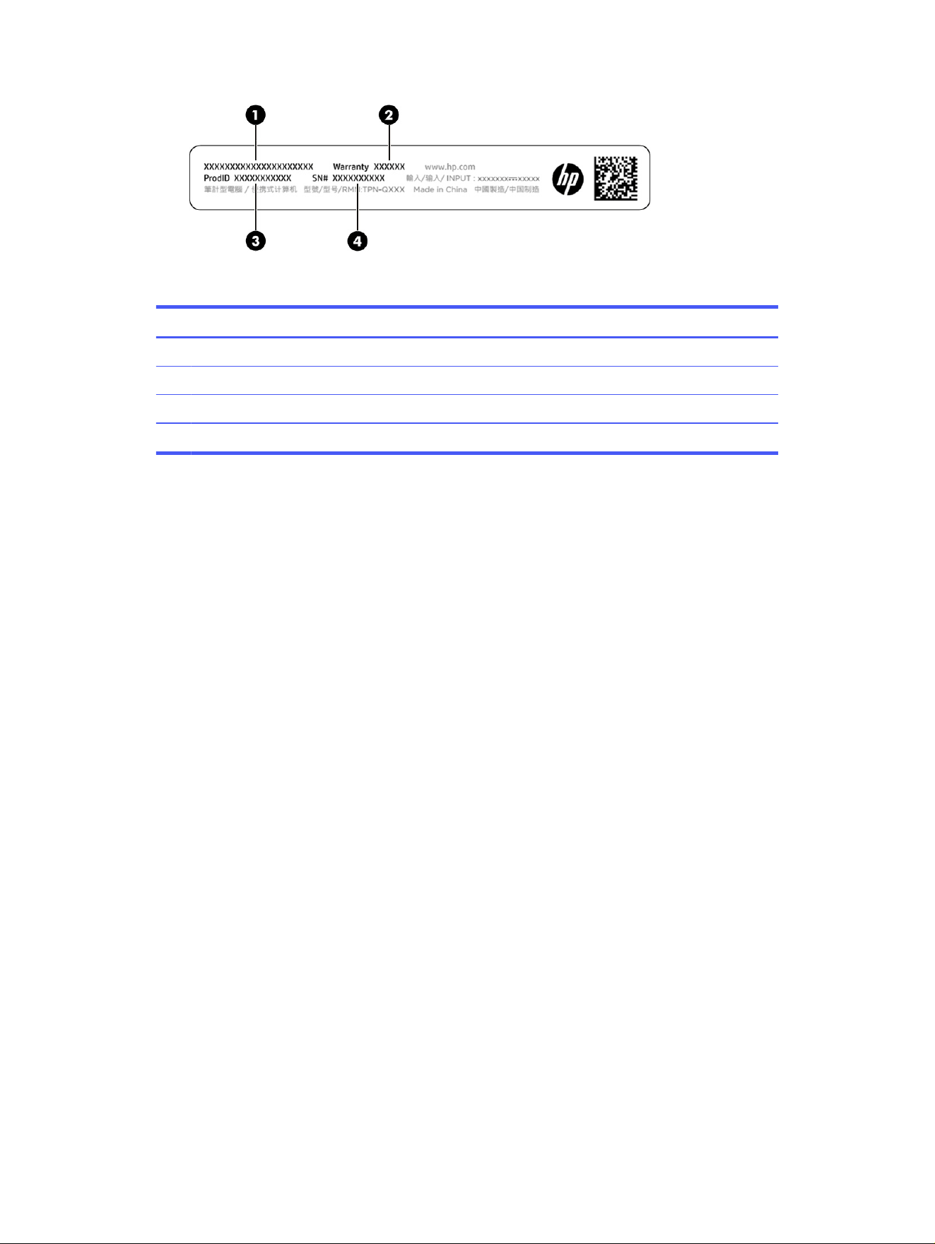
Table 2-9 Service label components
Component
(1) HP product name
(2) Warranty period
(3) Product ID
(4) Serial number
● Regulatory labels—Provide regulatory information about the computer.
● Wireless certification labels—Provide information about optional wireless devices and the approval
markings for the countries or regions where the devices have been approved for use.
Labels
9
Illustrated parts catalog3
Use this chapter to determine the spare parts that are available for the computer.
Chromebook major components
To identify the Chromebook™ major components, use this illustration and table.
NOTE: HP continually improves and changes product parts. For complete and current information
about supported parts for your computer, go to http://partsurfer.hp.com, select your country or region,
and then follow the on-screen instructions.
NOTE: Details about your computer, including model, serial number, product key, and length of
warranty, are on the service tag at the bottom of your computer.
10
Chapter 3 Illustrated parts catalog

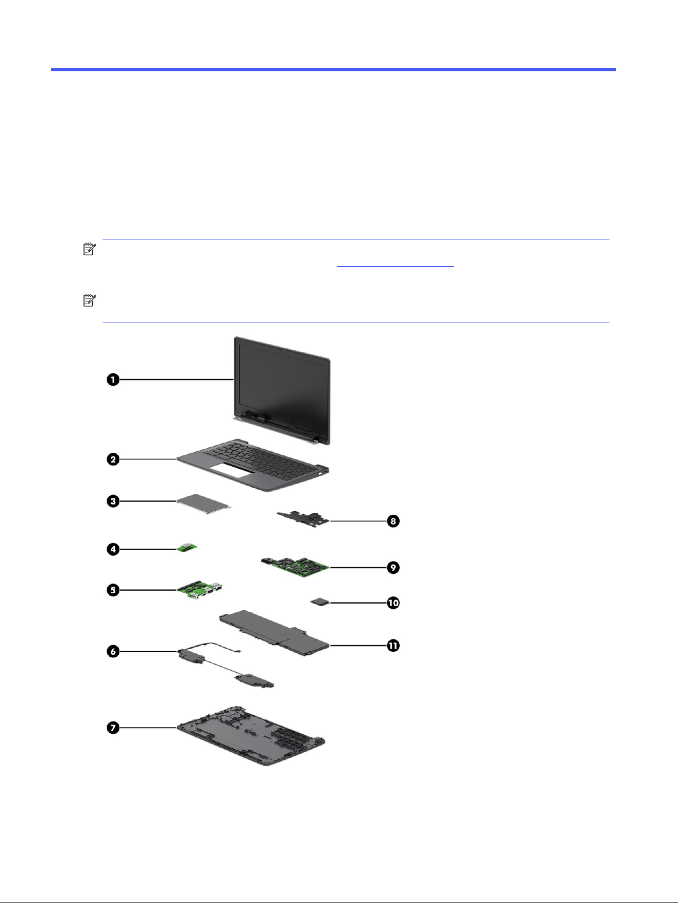
Table 3-1 Computer major component descriptions and part numbers
Item Component Spare part number
(1) Display assembly
NOTE: Display assemblies are offered as spare parts only at a subcomponent level. For
more information, see Display assembly subcomponents on page 11.
(2) Top cover with keyboard
For a detailed list of country codes, see Top cover with keyboard on page 51.
P24048-xx1
(3) Touchpad (includes cable)
NOTE: Touchpad protective tape is available as spare part number P24055-001.
The touchpad bracket is available in the Bracket Kit as spare part number P24054-001.
P22935-001
(4) I/O boards (left, includes cable)
NOTE: I/O support brackets are available in the Bracket Kit as spare part number
P24054-001.
P24053-001
(5) I/O boards (right, includes cable) P24053-001
(6) Speakers (includes cable) P24058-001
(7) Bottom cover P24057-001
(8) Heat sink (includes replacement thermal material) P22934-001
(9) System board (includes processor, replacement thermal material, and the Chrome operating
system)
MediaTek MT8186 processor, 8 GB system memory, 64 GB eMMC memory P24052-001
MediaTek MT8186 processor, 8 GB system memory, 32 GB eMMC memory P24051-001
MediaTek MT8186 processor, 4 GB system memory, 64 GB eMMC memory P24050-001
MediaTek MT8186 processor, 4 GB system memory, 32 GB eMMC memory P24049-001
(10) WLAN module (MediaTek MT7921 Wi-Fi 6 + Bluetooth 5.3) N85245-001
(11) Battery P24056-001
Display assembly subcomponents
To identify the display assembly subcomponents, use this illustration and table.
Display assembly subcomponents
11
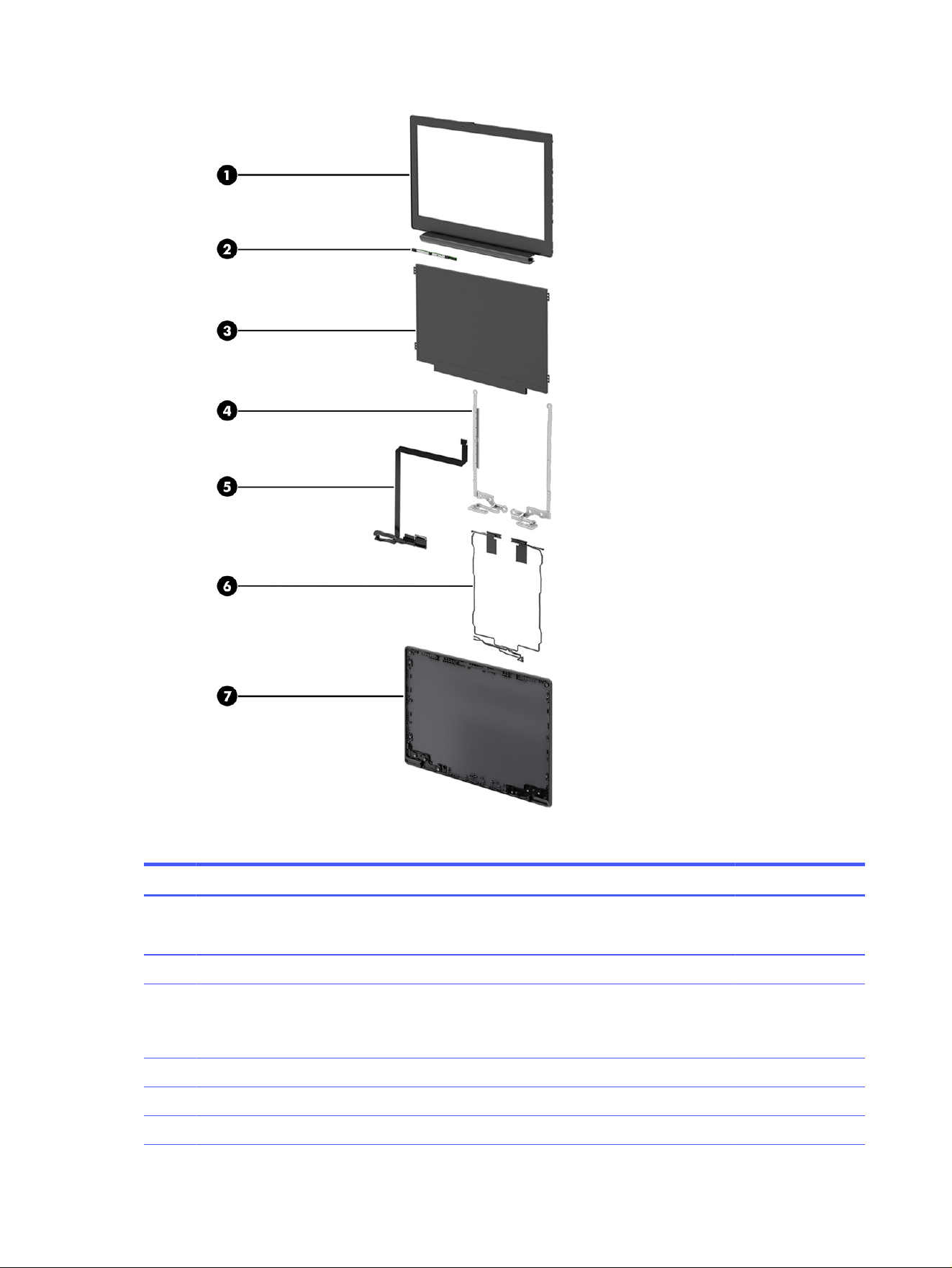
Table 3-2 Display component descriptions and part numbers
Item Component Spare part number
(1) Display bezel (includes hinge cover)
NOTE: The bezel support kit is available in the Bracket Kit as spare part number P24054-001.
P24063-001
(2) Camera module P24064-001
(3) Display panel (includes cable)
NOTE: The display support bracket is available in the Bracket Kit as spare part number
P24054-001.
SVA P24060-001
UWVA P24061-001
UWVA, touch panel P24062-001
12 Chapter 3 Illustrated parts catalog

Table 3-2 Display component descriptions and part numbers (continued)
Item Component Spare part number
(4) Hinges (includes left and right display hinges) P24066-001
(5) Display cable (includes cables for touch and nontouch displays) P24067-001
(6) WWAN antennas and cables P24065-001
(7) Display back cover (includes wireless antennas) P24059-001
Miscellaneous parts
To identify the miscellaneous parts, use this table.
Table 3-3
Miscellaneous part descriptions and part numbers
Component Spare part number
AC adapter
120 W (PFC, 4.5 mm) M95377-001
65 W (USB Type-C®, non-PFC 1.8 m [6 ft], halogen free) N90678-001
45 W (USB Type-C, non-PFC 1.8 m [6 ft]) L43407-001
Cable Kit (includes I/O board cables, touchpad cable, touch cable, display cable, camera cable P22937-001
Bracket Kit (includes I/O brackets, USB-C® bracket, touchpad bracket, display support bracket,
bezel support kit, bezel adhesive, and bezel pull tape)
P24054-001
Plastics Kit (includes touchpad protective tape) P24055-001
USB-C to USB-A adapter L65254-001
USB-C (male)-to-USB-C-(male) cable, 1 m (3.3 ft) L65253-001
HP Prelude Pro 15.6 Backpack M03617-001
HP Prelude Pro 15.6 Top Load Case M03618-001
HP Prelude 15.6 Backpack M16116-001
HP Prelude 15.6 Top Load Case M16117-001
HP USB-C Dock (with cable) L64086-001
Screw Kit for HP USB-C Dock L64089-001
Bottom case for HP USB-C Dock L65256-001
Screw Kit P22943-001
Duckhead power connector (for use in Japan)
Japan L33157-001
Power cord (C5, 1.0 m [3.3 ft], conventional with sticker)
For use in Argentina L19357-001
For use in Australia L19358-001
For use in Brazil L19359-001
For use in Denmark L19360-001
Miscellaneous parts 13

Table 3-3 Miscellaneous part descriptions and part numbers (continued)
Component Spare part number
For use in Denmark (halogen free) M79264-001
For use in Europe (bundle) N16170-001
For use in Europe L19361-001
For use in Europe (halogen free) M79266-001
For use in India L19363-001
For use in Italy L19364-001
For use in Israel L19362-001
For use in Israel (halogen free) M82712-001
For use in Japan L19365-001
For use in North America L19367-001
For use in the People's Republic of China L19368-001
For use in South Africa L19369-001
For use in South Korea L19366-001
For use in Switzerland L19370-001
For use in Switzerland (halogen free) M79265-001
For use in Taiwan L19372-001
For use in Thailand (bundle) M85418-001
For use in Thailand L19371-001
For use in the United Kingdom L19373-001
For use in the United Kingdom (halogen free) M82711-001
Power cord (C5, 1.8 m [6.0 ft], conventional with sticker)
For use in Argentina L19357-002
For use in Australia L19358-002
For use in Brazil L19359-002
For use in Brazil (duckhead) L19341-002
For use in Denmark L19360-002
For use in Europe (bundle) N16170-002
For use in Europe L19361-002
For use in India L19363-002
For use in Italy L19364-002
For use in Israel L19362-002
For use in Japan L19365-002
For use in North America L19367-002
For use in the People's Republic of China L19368-002
14 Chapter 3 Illustrated parts catalog

Table 3-3 Miscellaneous part descriptions and part numbers (continued)
Component Spare part number
For use in South Africa L19369-002
For use in South Korea L19366-002
For use in Switzerland L19370-002
For use in Taiwan L19372-002
For use in Thailand (bundle) M85418-002
For use in Thailand L19371-002
For use in the United Kingdom L19373-002
Miscellaneous parts 15

Removal and replacement procedures
preliminary requirements
4
Use this information to properly prepare to disassemble and reassemble the computer.
Tools required
You need the following tools to complete the removal and replacement procedures:
● Tweezers
● Nonconductive, nonmarking pry tool
● Magnetic Phillips P1 screwdriver
Service considerations
The following sections include some of the considerations that you must keep in mind during
disassembly and assembly procedures.
NOTE: As you remove each subassembly from the computer, place the subassembly and all
accompanying screws away from the work area to prevent damage.
Plastic parts
Using excessive force during disassembly and reassembly can damage plastic parts.
Cables and connectors
Handle cables with extreme care to avoid damage.
IMPORTANT: When servicing the computer, be sure that cables are placed in their proper locations
during the reassembly process. Improper cable placement can damage the computer.
Apply only the tension required to unseat or seat the cables during removal and insertion. Handle cables
by the connector whenever possible. In all cases, avoid bending, twisting, or tearing cables. Be sure that
cables are routed so that they cannot be caught or snagged as you remove or replace parts. Handle flex
cables with extreme care; these cables tear easily.
Drive handling
Note the following guidelines when handling drives.
IMPORTANT: Drives are fragile components. Handle them with care. To prevent damage to the
computer, damage to a drive, or loss of information, observe these precautions:
● Before removing or inserting a hard drive, shut down the computer. If you are unsure whether the
computer is off or in Hibernation or Sleep mode, turn the computer on, and then shut it down
through the operating system.
16
Chapter 4 Removal and replacement procedures preliminary requirements

● Before handling a drive, be sure that you are discharged of static electricity. While handling a drive,
avoid touching the connector.
● Before removing an optical drive, be sure that a disc is not in the drive, and be sure that the optical
drive tray is closed.
● Handle drives on surfaces covered with at least 2.54 cm (1 inch) of shock-proof foam.
● Avoid dropping drives from any height onto any surface.
● After removing a hard drive or an optical drive, place it in a static-proof bag.
● Avoid exposing an internal hard drive to products that have magnetic fields, such as monitors or
speakers.
● Avoid exposing a drive to temperature extremes or liquids.
● If a drive must be mailed, place the drive in a bubble pack mailer or other suitable form of
protective packaging, and label the package “FRAGILE.”
Electrostatic discharge information
A sudden discharge of static electricity from your finger or other conductor can destroy static-sensitive
devices or microcircuitry. Often the spark is neither felt nor heard, but damage occurs. An electronic
device exposed to electrostatic discharge (ESD) might not appear to be affected at all and can work
perfectly throughout a normal cycle. The device might function normally for a while, but it has been
degraded in the internal layers, reducing its life expectancy.
Networks built into many integrated circuits provide some protection, but in many cases, the discharge
contains enough power to alter device parameters or melt silicon junctions.
IMPORTANT: To prevent damage to the device when you remove or install internal components,
observe these precautions:
● Keep components in their electrostatic-safe containers until you are ready to install them.
● Before touching an electronic component, discharge static electricity by using the guidelines
described in Personal grounding methods and equipment on page 18.
● Avoid touching pins, leads, and circuitry. Handle electronic components as little as possible.
● If you remove a component, place it in an electrostatic-safe container.
Generating static electricity
Follow these static electricity guidelines:
● Different activities generate different amounts of static electricity.
● Static electricity increases as humidity decreases.
Electrostatic discharge information
17

Table 4-1 Static electricity occurrence based on activity and humidity
Event 55% relative humidity 40% relative humidity 10% relative humidity
Walking across carpet
Walking across vinyl floor
Motions of bench worker
Removing dual in-line packages (DIPs)
from plastic tube
7,500 V
3,000 V
400 V
400 V
15,000 V
5,000 V
800 V
700 V
35,000 V
12,000 V
6,000 V
2,000 V
Removing DIPs from vinyl tray
Removing DIPs from polystyrene foam
Removing bubble pack from PCB
(printed circuit board)
Packing PCBs in foam-lined box
2,000 V
3,500 V
7,000 V
5,000 V
4,000 V
5,000 V
20,000 V
11,000 V
11,500 V
14,500 V
26,500 V
21,000 V
NOTE: Multiple electric components can be packaged together in plastic tubes, trays, or polystyrene
foam.
As little as 700 V of static electricity can degrade a product.
Preventing electrostatic damage to equipment
Many electronic components are sensitive to ESD. Circuitry design and structure determine the degree
of sensitivity.
The following packaging and grounding precautions are necessary to prevent static electricity damage
to electronic components:
● To avoid hand contact, transport products in static-safe containers such as tubes, bags, or boxes.
● Protect all electrostatic parts and assemblies with conductive or approved containers or packaging.
● Keep electrostatic-sensitive parts in their containers until they arrive at static-free stations.
● Place items on a grounded surface before removing them from their container.
● Always be properly grounded when touching a sensitive component or assembly.
● Avoid contact with pins, leads, or circuitry.
● Place reusable electrostatic-sensitive parts from assemblies in protective packaging or conductive
foam.
Personal grounding methods and equipment
Using certain equipment can prevent static electricity damage to electronic components.
● Wrist straps are flexible straps with a maximum of 1 MΩ ±10% resistance in the ground cords. To
provide proper ground, wear a strap snug against bare skin. Verify that the ground cord is connected
and fits snugly into the banana plug connector on the grounding mat or workstation.
18
Chapter 4 Removal and replacement procedures preliminary requirements

● You can use heel straps, toe straps, and boot straps at standing workstations. These straps are
compatible with most types of shoes or boots. On conductive floors or dissipative floor mats, use
them on both feet with a maximum of 1 MΩ ±10% resistance between the operator and ground.
Table 4-2 Static shielding protection levels
Method Voltage
Antistatic plastic
Carbon-loaded plastic
Metallized laminate
1,500
7,500
15,000
Grounding the work area
To prevent static damage at the work area, follow these precautions:
● Cover the work surface with approved static-dissipative material.
● Use a wrist strap connected to a properly grounded work surface and use properly grounded tools
and equipment.
● Use static-dissipative mats, foot straps, or air ionizers to give added protection.
● Handle electrostatic sensitive components, parts, and assemblies by the case or PCB laminate.
Handle them only at static-free work areas.
● Turn off power and input signals before inserting and removing connectors or test equipment.
● Use fixtures made of static-safe materials when fixtures must directly contact dissipative surfaces.
● Keep the work area free of nonconductive materials, such as ordinary plastic assembly aids and
polystyrene foam.
● Use conductive field service tools, such as cutters, screwdrivers, and vacuums.
● Avoid contact with pins, leads, or circuitry.
Recommended materials and equipment
HP recommends certain materials and equipment to prevent static electricity:
● Antistatic tape
● Antistatic smocks, aprons, or sleeve protectors
● Conductive bins and other assembly or soldering aids
● Conductive foam
● Conductive tabletop workstations with ground cord of 1 MΩ ±10% resistance
● Static-dissipative table or floor mats with hard tie to ground
● Field service kits
● Static awareness labels
● Wrist straps and footwear straps providing 1 MΩ ±10% resistance
Grounding the work area
19

● Material handling packages
● Conductive plastic bags
● Conductive plastic tubes
● Conductive tote boxes
● Opaque shielding bags
● Transparent metallized shielding bags
● Transparent shielding tubes
Cleaning your computer
Cleaning your computer regularly removes dirt and debris so that your device continues to operate at its
best. Use the following information to safely clean the external surfaces of your computer.
Enabling HP Easy Clean (select products only)
HP Easy Clean helps you to avoid accidental input while you clean the computer surfaces. This software
disables devices such as the keyboard, touch screen, and touchpad for a preset amount of time so that
you can clean all computer surfaces.
1. Start HP Easy Clean in one of the following ways:
● Select the Start menu, and then select HP Easy Clean.
● Select the HP Easy Clean icon in the taskbar.
● Select Start, and then select the HP Easy Clean tile.
2. Now that your device is disabled for a short period, see Removing dirt and debris from your
computer on page 20 for the recommended steps to clean the high-touch, external surfaces
on your computer. After you remove the dirt and debris, you can also clean the surfaces with a
disinfectant. See Cleaning your computer with a disinfectant on page 21 for guidelines to help
prevent the spread of harmful bacteria and viruses.
Removing dirt and debris from your computer
Here are the recommended steps to clean dirt and debris from your computer.
For computers with wood veneer, see Caring for wood veneer (select products only) on page 22.
1. Wear disposable gloves made of latex (or nitrile gloves, if you are latex-sensitive) when cleaning the
surfaces.
2. Turn off your device and unplug the power cord and other connected external devices. Remove any
installed batteries from items such as wireless keyboards.
CAUTION: To prevent electric shock or damage to components, never clean a product while it is
turned on or plugged in.
3. Moisten a microfiber cloth with water. The cloth should be moist, but not dripping wet.
IMPORTANT: To avoid damaging the surface, avoid abrasive cloths, towels, and paper towels.
20
Chapter 4 Removal and replacement procedures preliminary requirements

4. Wipe the exterior of the product gently with the moistened cloth.
IMPORTANT: Keep liquids away from the product. Avoid getting moisture in any openings. If liquid
makes its way inside your HP product, it can cause damage to the product. Do not spray liquids
directly on the product. Do not use aerosol sprays, solvents, abrasives, or cleaners containing
hydrogen peroxide or bleach that might damage the finish.
5. Start with the display (if applicable). Wipe carefully in one direction, and move from the top of the
display to the bottom. Finish with any flexible cables, like power cord, keyboard cable, and USB
cables.
6. Be sure that surfaces have completely air-dried before turning the device on after cleaning.
7. Discard the gloves after each cleaning. Clean your hands immediately after you remove the gloves.
See Cleaning your computer with a disinfectant on page 21 for recommended steps to clean the
high-touch, external surfaces on your computer to help prevent the spread of harmful bacteria and
viruses.
Cleaning your computer with a disinfectant
The World Health Organization (WHO) recommends cleaning surfaces, followed by disinfection, as a
best practice for preventing the spread of viral respiratory illnesses and harmful bacteria.
After cleaning the external surfaces of your computer using the steps in Removing dirt and debris from
your computer on page 20, Caring for wood veneer (select products only) on page 22, or both, you
might also choose to clean the surfaces with a disinfectant. A disinfectant that is within HP’s cleaning
guidelines is an alcohol solution consisting of 70% isopropyl alcohol and 30% water. This solution is also
known as rubbing alcohol and is sold in most stores.
Follow these steps when disinfecting high-touch, external surfaces on your computer:
1. Wear disposable gloves made of latex (or nitrile gloves, if you are latex-sensitive) when cleaning the
surfaces.
2. Turn off your device and unplug the power cord and other connected external devices. Remove any
installed batteries from items such as wireless keyboards.
CAUTION: To prevent electric shock or damage to components, never clean a product while it is
turned on or plugged in.
3. Moisten a microfiber cloth with a mixture of 70% isopropyl alcohol and 30% water. The cloth should
be moist, but not dripping wet.
CAUTION: Do not use any of the following chemicals or any solutions that contain them, including
spray-based surface cleaners: bleach, peroxides (including hydrogen peroxide), acetone, ammonia,
ethyl alcohol, methylene chloride, or any petroleum-based materials, such as gasoline, paint thinner,
benzene, or toluene.
IMPORTANT: To avoid damaging the surface, avoid abrasive cloths, towels, and paper towels.
4. Wipe the exterior of the product gently with the moistened cloth.
IMPORTANT: Keep liquids away from the product. Avoid getting moisture in any openings. If liquid
makes its way inside your HP product, it can cause damage to the product. Do not spray liquids
directly on the product. Do not use aerosol sprays, solvents, abrasives, or cleaners containing
hydrogen peroxide or bleach that might damage the finish.
Cleaning your computer with a disinfectant
21

5. Start with the display (if applicable). Wipe carefully in one direction, and move from the top of the
display to the bottom. Finish with any flexible cables, like power cord, keyboard cable, and USB
cables.
6. Be sure that surfaces have completely air-dried before turning the device on after cleaning.
7. Discard the gloves after each cleaning. Clean your hands immediately after you remove the gloves.
Caring for wood veneer (select products only)
Your product might feature high-quality wood veneer. As with all natural wood products, proper care is
important for best results over the life of the product. Because of the nature of natural wood, you might
see unique variations in the grain pattern or subtle variations in color, which are normal.
● Clean the wood with a dry, static-free microfiber cloth or chamois.
● Avoid cleaning products containing substances such as ammonia, methylene chloride, acetone,
turpentine, or other petroleum-based solvents.
● Do not expose the wood to sun or moisture for long periods of time.
● If the wood becomes wet, dry it by dabbing with an absorbent, lint-free cloth.
● Avoid contact with any substance that might dye or discolor the wood.
● Avoid contact with sharp objects or rough surfaces that might scratch the wood.
See Removing dirt and debris from your computer on page 20 for the recommended steps to clean
the high-touch, external surfaces on your computer. After you remove the dirt and debris, you can also
clean the surfaces with a disinfectant. See Cleaning your computer with a disinfectant on page 21 for
sanitizing guidelines to help prevent the spread of harmful bacteria and viruses.
Packaging and transporting guidelines
Follow these grounding guidelines when packaging and transporting equipment:
● To avoid hand contact, transport products in static-safe tubes, bags, or boxes.
● Protect ESD-sensitive parts and assemblies with conductive or approved containers or packaging.
● Keep ESD-sensitive parts in their containers until the parts arrive at static-free workstations.
● Place items on a grounded surface before removing items from their containers.
● Always be properly grounded when touching a component or assembly.
● Store reusable ESD-sensitive parts from assemblies in protective packaging or
nonconductive foam.
● Use transporters and conveyors made of antistatic belts and roller bushings. Be sure that
mechanized equipment used for moving materials is wired to ground and that proper materials
are selected to avoid static charging. When grounding is not possible, use an ionizer to dissipate
electric charges.
Accessing support information
To find the HP support that you need, use this information.
22
Chapter 4 Removal and replacement procedures preliminary requirements

Table 4-3 Support information locations
Service consideration Path to access information
Records of reported failure incidents stored
on the computer
Windows®:
Preoperating system failures are logged in the BIOS Event Log. To view the BIOS
Event Log:
1. Press the power button.
2. Immediately and repeatedly press esc when the power button light turns
white.
NOTE: If you do not press esc at the appropriate time, you must restart the
computer and again repeatedly press esc when the power button light turns
white to access the utility.
3. Press f10 to enter the BIOS setup.
4. Complete one of these tasks:
● (On commercial products) Under the Main tab, select BIOS event log,
and then select
View BIOS Event Log.
● (On consumer products) Under the Main tab, select System Log.
Post-operating system failures are logged in the Event Viewer.
1. Turn on the computer and allow the operating system to open.
2. Select the search icon in the taskbar.
3. Type Event Viewer, and then press enter.
4. Select the log from the left panel. Details display in the right panel.
Chrome™:
1. Go to support.google.com/chrome.
2. Search collect Chrome device logs.
Technical bulletins
To locate technical bulletins:
1. Go to www.hp.com.
2. Place the cursor over Problem solving to display more options.
3. Select Support & Troubleshooting.
4. Type the serial number, product number, or product name to go to the
product support page.
5. Select Advisories to view technical bulletins.
Repair professionals To locate repair professionals:
1. Go to www.hp.com.
2. Place the cursor over Support resources to display more options.
3. Select Authorized service providers.
Accessing support information 23

Table 4-3 Support information locations (continued)
Service consideration Path to access information
Component and diagnosis information,
failure detection, and required action
To locate diagnosis information and actions:
1. Go to http://www.hp.com/go/techcenter/pcdiags.
2. Select Get Support.
3. Near the bottom of the window, select Notebook PCs, and then select your
location.
24 Chapter 4 Removal and replacement procedures preliminary requirements

Removal and replacement procedures for
Customer Self-Repair parts
5
This chapter provides removal and replacement procedures for Customer Self-Repair parts.
NOTE: The Customer Self-Repair program is not available in all locations. Installing a part that is not
supported by the Customer Self-Repair program can void your warranty. Check your warranty to
determine whether Customer Self-Repair is supported in your location.
NOTE: The HP Support YouTube Channel (in English) has videos that provide step-by-step removal
and replacement instructions for many common parts and models.
Component replacement procedures
To remove and replace computer components, use these procedures.
NOTE: Details about your computer, including model, serial number, product key, and length of
warranty, are on the service tag at the bottom of your computer.
NOTE: HP continually improves and changes product parts. For complete and current information
about supported parts for your computer, go to https://partsurfer.hp.com/, select your country or
region, and then follow the on-screen instructions.
Make special note of each screw size and location during removal and replacement.
Preparation for disassembly
To remove and replace computer components, use these procedures:
For initial safety procedures, see Removal and replacement procedures preliminary requirements on
page 16.
1. Turn off the computer. If you are unsure whether the computer is off or in Hibernation or Sleep
mode, turn the computer on, and then shut it down through the operating system.
2. Disconnect the power from the computer by unplugging the power cord from the computer.
3. Disconnect all external devices from the computer.
Battery
The battery removal procedure differs depending on whether you are removing and replacing the
existing battery or installing a new battery. To install a new battery, you must use a revive kit.
● To remove and replace the existing battery, see Removing and reinstalling the same battery on page
26.
● To install a new battery, see Installing a new battery on page 27.
Removal and replacement procedures for Customer Self-Repair parts
25

Removing and reinstalling the same battery
To remove the battery and reinstall it, use this procedure and illustration.
If you are replacing the battery you must use a revive kit. See Installing a new battery on page 27.
Table 5-1 Battery description and part number
Description Spare part number
3 cell, 41 Whr, Li-ion battery P24056-001
WARNING! To avoid personal injury and damage to the product:
● Do
not
puncture, twist, or crack the battery.
● Do
not
cause an external puncture or rupture to the battery. Punctures can cause a short inside
the battery, which can result in battery thermal runaway.
● Do
not
handle or touch the battery enclosure with sharp objects such as tweezers or pliers, which
might puncture the battery.
● Do
not
compress or squeeze the battery case with tools or heavy objects stacked on top of the
case. These actions can apply undue force to the battery.
● Do
not
touch the connectors with any metallic surface or object, such as metal tools, screws, or
coins, which can cause shorting across the connectors.
Before removing the battery, follow these steps:
1. Prepare the computer for disassembly (see Preparation for disassembly on page 25).
2. Remove the bottom cover (see Bottom cover on page 32).
WARNING! To reduce potential safety issues, use only the user-replaceable battery provided with the
computer, a replacement battery provided by HP, or a compatible battery purchased from HP.
IMPORTANT: Removing a battery that is the sole power source for the computer can cause loss of
information. To prevent loss of information, save your work or shut down the computer through
Windows before you remove the battery.
Remove the battery:
1. Remove the speaker cable from the clips (1) along the bottom of the battery.
2. Remove the six Phillips M2.0 × 4.0 screws (2) that secure the battery to the computer.
26
Chapter 5 Removal and replacement procedures for Customer Self-Repair parts
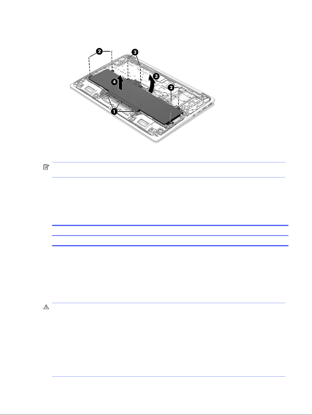
3. Lift the top of the battery (3) up, and then remove the battery from the computer (4).
To reinstall the battery, reverse the removal procedures.
NOTE: When replacing the battery, be sure to completely reassemble the computer and plug in the
AC adapter before turning the computer on.
Installing a new battery
To replace the battery, use these procedures and illustrations. You must use a revive kit to remove the
old battery and install a new one. The revive kit includes an empty containment tray and a containment
tray with a battery preinstalled.
Table 5-2
Battery description and part number
Description Spare part number
3 cell, 41 Whr, Li-ion battery P24056-001
Before starting this replacement procedure:
● Ensure other individuals are sufficiently clear of your workspace.
● Ensure your workspace is clear of any flammable material such as paper or oils.
● Locate the nearest ABC dry chemical fire-extinguisher for use in an emergency.
WARNING! This procedure requires removing the battery or disconnecting the battery cable. Use
care to avoid bending, twisting, or puncturing the battery regardless of its condition. Failure to follow
this replacement guide or to use HP recommended tools might damage the system and/or cause a
safety hazard.
● Do
not
remove the battery from the containment tray.
● Do
not
handle or touch the battery enclosure with sharp objects such as tweezers or pliers, which
might puncture the battery.
● Do
not
touch the connectors with any metallic surface or object, such as metal tools, screws, or
coins, which can cause shorting across the connectors.
Installing a new battery
27
Should a part become stuck or difficult to remove when opening a unit where a swollen battery is
suspected, or if the battery becomes stuck in the unit, stop, and contact HP Support for assistance. Do
not try to remove a battery by force.
NOTE: Screw locations, latch locations, and internal components might vary.
Before removing the battery, follow these steps:
1. Prepare the computer for disassembly (see Preparation for disassembly on page 25).
2. Remove the bottom cover (see Bottom cover on page 32).
WARNING! To reduce potential safety issues, use only the user-replaceable battery provided with the
computer, a replacement battery provided by HP, or a compatible battery purchased from HP.
IMPORTANT: Removing a battery that is the sole power source for the computer can cause loss of
information. To prevent loss of information, save your work or shut down the computer through
Windows before you remove the battery.
Remove the battery:
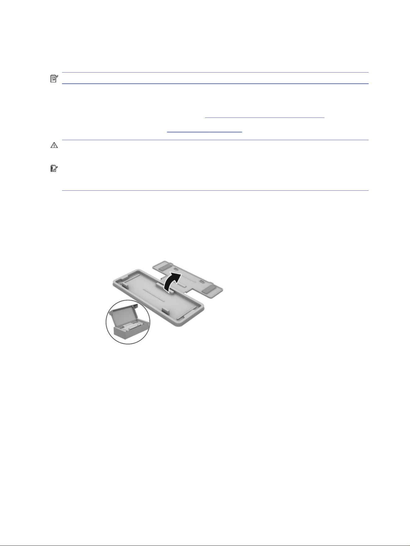
1. To remove the battery using the revive kit:
a. Open the empty battery containment tray.
28
Chapter 5 Removal and replacement procedures for Customer Self-Repair parts
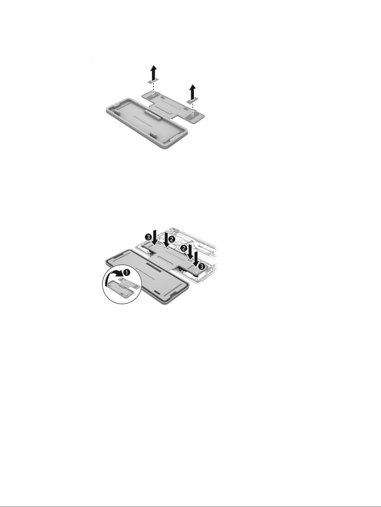
b. Remove the backing from the adhesive on the tray.
c. Turn the tray (1) over so that the adhesive is facing down.
d. Place the tray (2) centered on the battery.
e. Press down on the indentations on the tray (3) to adhere it to the battery.
f. Remove the Phillips screws (1) that secure the battery to the computer. Screw locations might
vary.
Installing a new battery
29
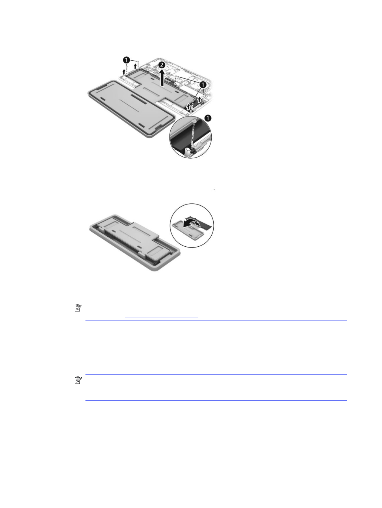
g. Lift the top of the tray (2) to remove the battery from the computer.
h. Rotate the battery up and over into the cavity of the containment tray.
NOTE: Please recycle responsibly. For more information about recycling programs, see the
HP website at http://www.hp.com/recycle.
2. To install the battery using the revive kit:
a. Open the containment tray that includes the new battery.
b. Turn the tray (1) over so the battery is facing downward, and then insert the battery (2) into the
computer.
NOTE: To avoid damage when inserting the battery into the computer, be sure that the power
connector on the battery lines up and successfully mates with the connector on the system
board.
30
Chapter 5 Removal and replacement procedures for Customer Self-Repair parts
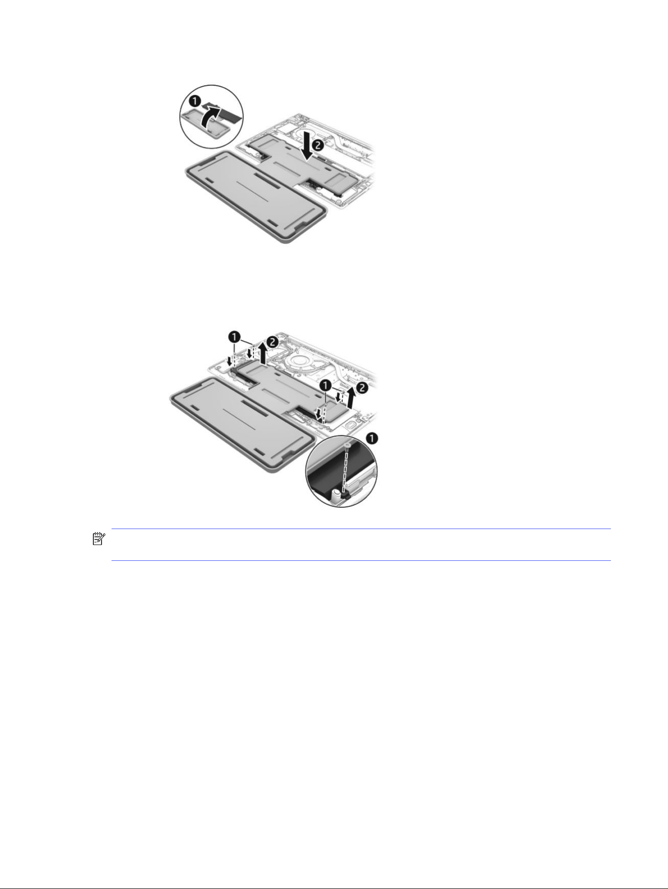
c. Install the screws (1) to secure the battery. Screw locations might vary.
d. Lift the containment tray (2) off the battery,
NOTE: When replacing the battery, be sure to completely reassemble the computer and plug in the
AC adapter before turning the computer on.
Installing a new battery
31

Removal and replacement procedures for
authorized service provider parts
6
This chapter provides removal and replacement procedures for authorized service provider parts.
IMPORTANT: Only an authorized service provider should access the components described in this
chapter. Accessing these parts can damage the computer or void the warranty.
NOTE: Details about your computer, including model, serial number, product key, and length of
warranty, are on the service tag at the bottom of your computer.
NOTE: The HP Support YouTube Channel (in English) has videos that provide step-by-step removal
and replacement instructions for many common parts and models.
Component replacement procedures
To remove and replace computer components, use the procedures described in this section.
NOTE: HP continually improves and changes product parts. For complete and current information
about supported parts for your computer, go to https://partsurfer.hp.com/partsurfer/, select your
country or region, and then follow the on-screen instructions.
Make special note of each screw size and location during removal and replacement.
Preparation for disassembly
To remove and replace computer components, use these procedures:
For initial safety procedures, see Removal and replacement procedures preliminary requirements on
page 16.
1. Turn off the computer. If you are unsure whether the computer is off or in Hibernation or Sleep
mode, turn the computer on, and then shut it down through the operating system.
2. Disconnect the power from the computer by unplugging the power cord from the computer.
3. Disconnect all external devices from the computer.
Bottom cover
To remove the bottom cover, use this procedure and illustration.
Table 6-1
Bottom cover description and part number
Description Spare part number
Bottom cover P24057-001
Before removing the bottom cover, prepare the computer for disassembly (Preparation for disassembly
on page 25).
32
Chapter 6 Removal and replacement procedures for authorized service provider parts
Remove the bottom cover:
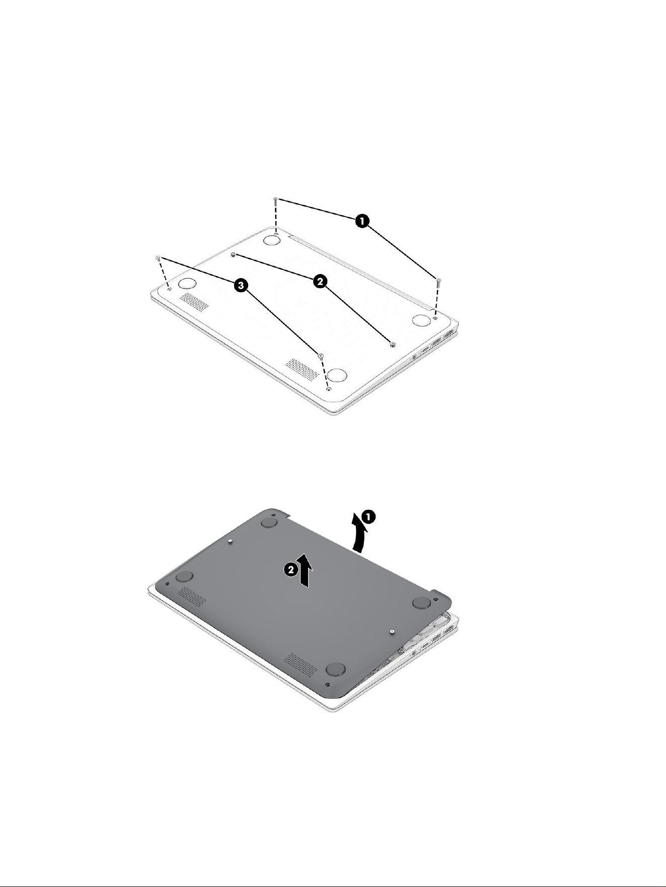
1. Position the computer upside down with the front toward you.
2. Remove the two Phillips M2.0 × 10.0 screws (1).
3. Loosen the two captive Phillips screws (2).
4. Remove the two Phillips M2.0 × 5.0 screws (3).
5. Separate the top edge of the bottom cover (1) from the computer.
6. Remove the bottom cover (2).
To install the bottom cover, reverse the removal procedures.
Speakers
To remove the speakers, use this procedure and illustration.
Speakers
33
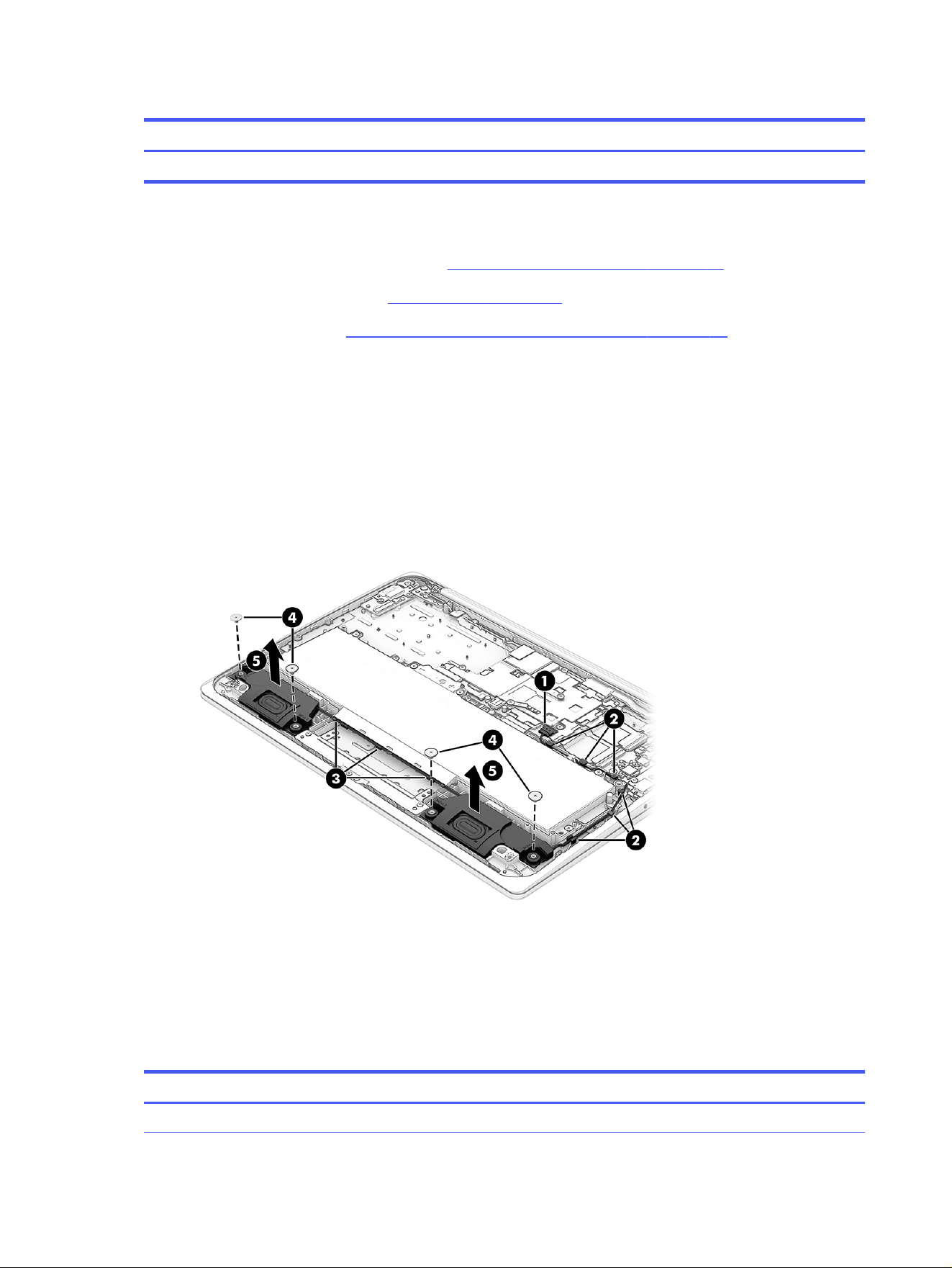
Table 6-2 Speakers description and part number
Description Spare part number
Speakers (includes cable) P24058-001
Before removing the speakers, follow these steps:
1. Prepare the computer for disassembly (Preparation for disassembly on page 25).
2. Remove the bottom cover (see Bottom cover on page 32).
3. Remove the battery (see Removing and reinstalling the same battery on page 26).
Remove the speakers:
1. Disconnect the speaker cable (1) from the system board.
2. Remove the cable from the clips (2) along the right side and top right of the battery.
3. Remove the cable from the clips (3) along the bottom of the battery.
4. Remove the two Phillips M1.6 × 2.5 screws (4) from each speaker.
5. Remove the speakers (5) from the computer.
To install the speakers, reverse this procedure.
Touchpad
To remove the touchpad, use this procedure and illustration.
Table 6-3
Touchpad descriptions and part numbers
Description Spare part number
Touchpad (includes cable) P22935-001
34 Chapter 6 Removal and replacement procedures for authorized service provider parts
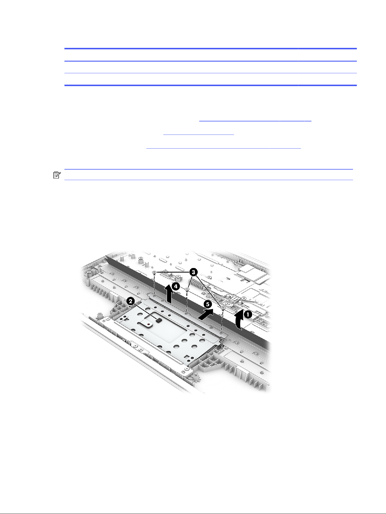
Table 6-3 Touchpad descriptions and part numbers (continued)
Description Spare part number
Touchpad bracket (included in the Bracket Kit) P24054-001
Touchpad protective tape P24055-001
Before removing the touchpad, follow these steps:
1. Prepare the computer for disassembly (see Preparation for disassembly on page 25).
2. Remove the bottom cover (see Bottom cover on page 32).
3. Remove the battery (see Removing and reinstalling the same battery on page 26).
Remove the touchpad:
NOTE: You do not have to remove the touchpad bracket before removing the touchpad.
1. Lift the large piece of clear tape (1) that covers the touchpad and connector.
2. Disconnect the cable from the ZIF connector (2) on the touchpad.
3. Remove the three Phillips M1.6 × 2.5 screws (3) from the touchpad.
4. Lift the top of the touchpad (4) up, and then pull the touchpad (5) into the computer to remove it from
under the bracket.
Touchpad
35
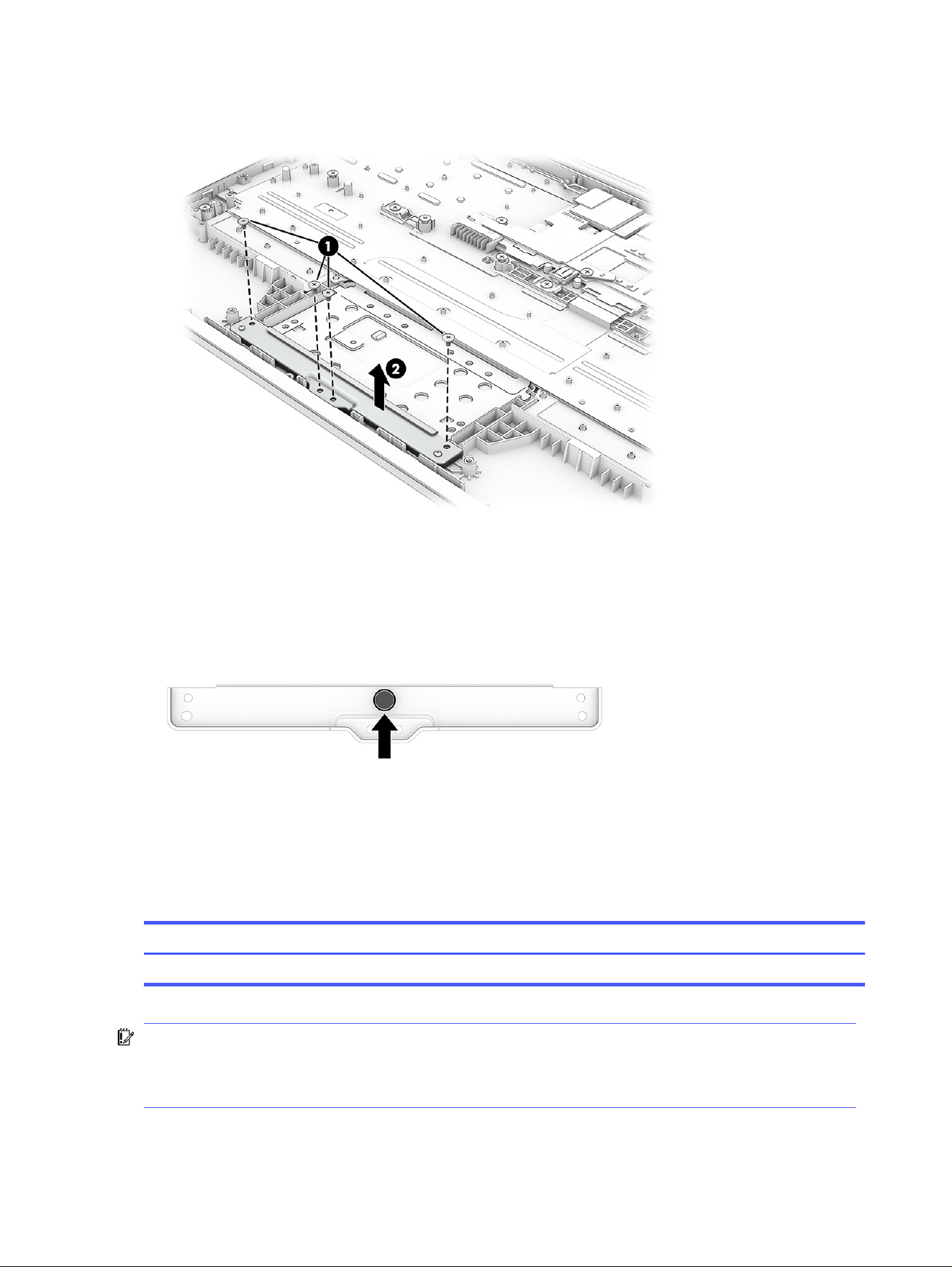
5. To remove the touchpad bracket, remove the four Phillips M1.6 × 2.5 screws (1) from the touchpad
bracket, and then remove the bracket (2).
To install the touchpad, reverse this procedure.
When installing the touchpad and bracket, be sure that the rubber bumper is installed on the bottom of
the touchpad bracket in the location shown in the following illustration.
WLAN module
To remove the WLAN module, use this procedure and illustration.
Table 6-4
WLAN module description and part number
Description Spare part number
MediaTek MT7921 Wi-Fi 6 + Bluetooth 5.3 P24069-001
IMPORTANT: To prevent an unresponsive system, replace the wireless module only with a wireless
module authorized for use in the computer by the governmental agency that regulates wireless
devices in your country or region. If you replace the module and then receive a warning message,
remove the module to restore device functionality, and then contact technical support.
Before removing the WLAN module, follow these steps:
36
Chapter 6 Removal and replacement procedures for authorized service provider parts
1. Prepare the computer for disassembly (Preparation for disassembly on page 25).
2. Remove the bottom cover (see Bottom cover on page 32).
3. Remove the battery (see Removing and reinstalling the same battery on page 26).
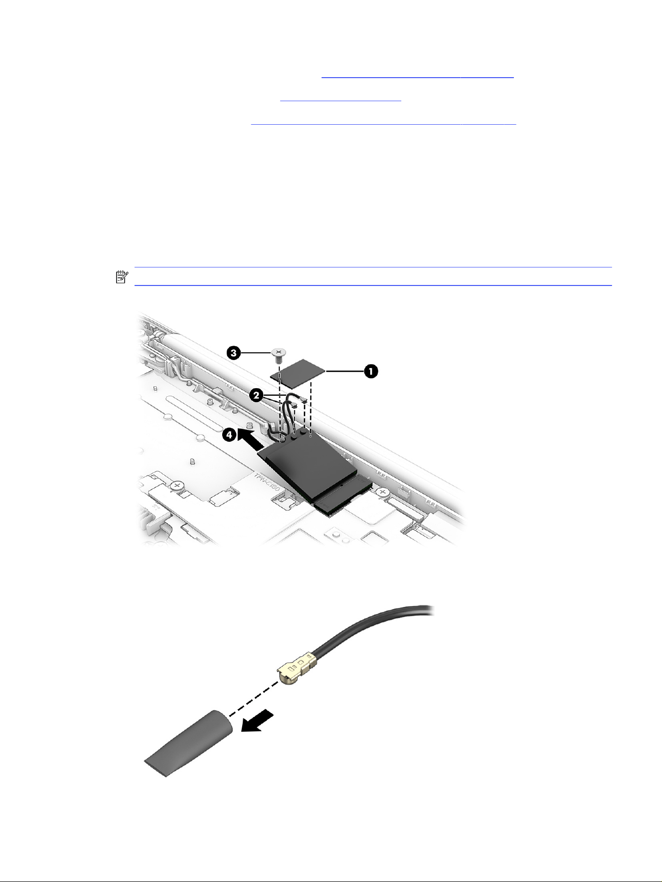
Remove the WLAN module:
1. Remove the plastic antenna protector (1) from the top of the module. The protector is secured with
adhesive.
2. Disconnect the antenna cables (2) from the module terminals.
3. Remove the Phillips M2.0 × 3.0 screw (3) that secures from the WLAN module.
4. Remove the module (4) by pulling it away from the slot at an angle.
NOTE: WLAN modules are notched to prevent incorrect installation.
5. If the WLAN antenna is not connected to the terminal on the WLAN module, install a protective
sleeve on the antenna connector, as shown in the following illustration.
WLAN module
37
To install the WLAN module, reverse this procedure.
I/O boards
To remove the I/O boards, use these procedures and illustrations.
Table 6-5 I/O board descriptions and part numbers
Description Spare part number
I/O boards (left and right, includes cables) P24053-001
I/O support brackets (available in the Bracket Kit) P24054-001
Before removing the I/O board, follow these steps:
1. Prepare the computer for disassembly (Preparation for disassembly on page 25).
2. Remove the bottom cover (see Bottom cover on page 32).
3. Remove the battery (see Removing and reinstalling the same battery on page 26).
Remove the I/O boards:
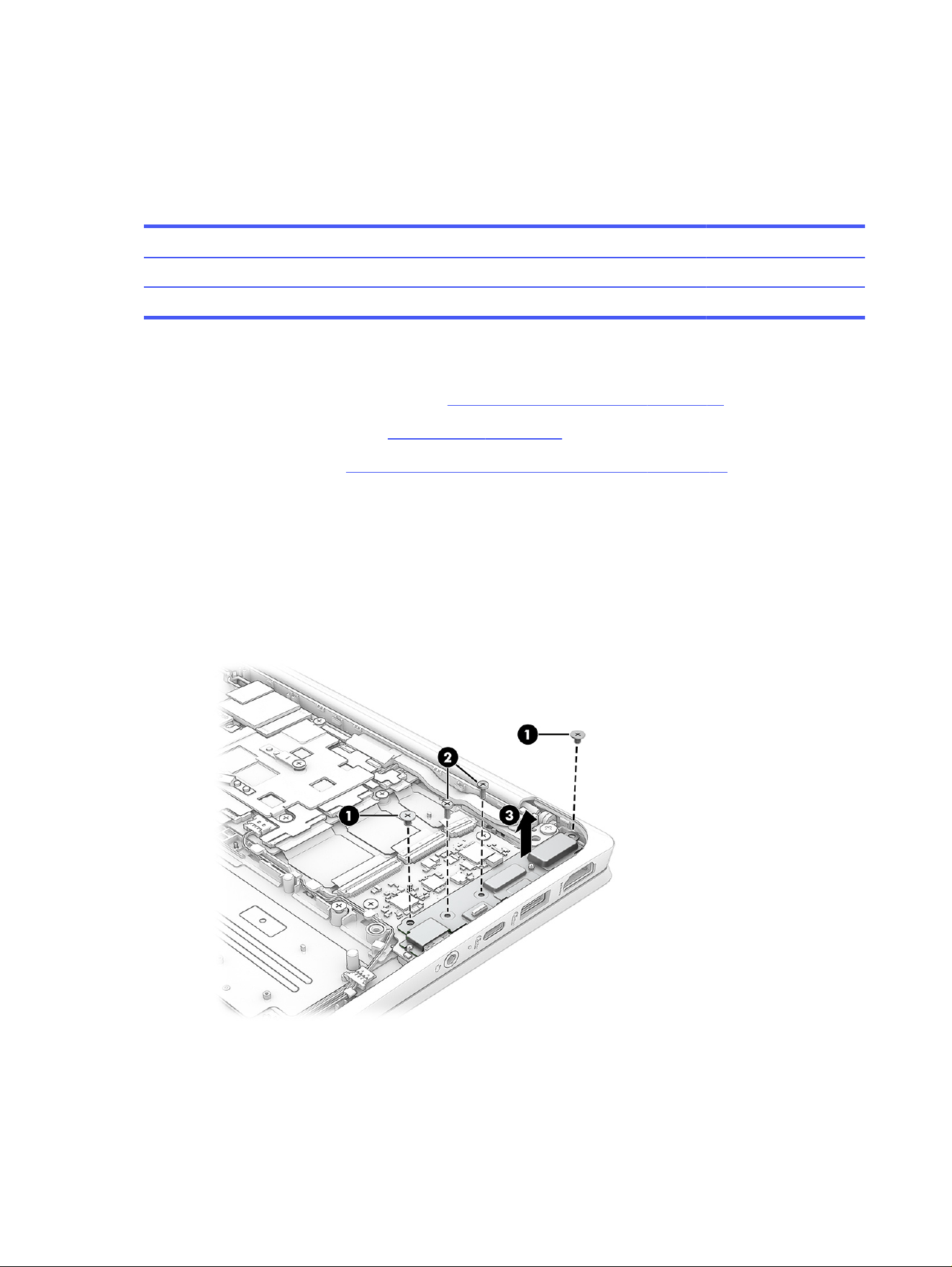
1. To remove the large I/O board:
a. Remove the two outer Phillips M2.0 × 2.5 screws (1) that secure the bracket to the board.
b. Remove the two inner Phillips M1.4 × 4.0 screws (2) that secure the bracket to the board.
c. Remove the bracket (3) from the board.
d. Lift (do not remove) the tape (1) from the connectors on the board.
e. Disconnect the cables from the ZIF connectors (2) on the board.
f. Remove the two Phillips M2.0 × 2.5 screws (3) from the board.
38
Chapter 6 Removal and replacement procedures for authorized service provider parts
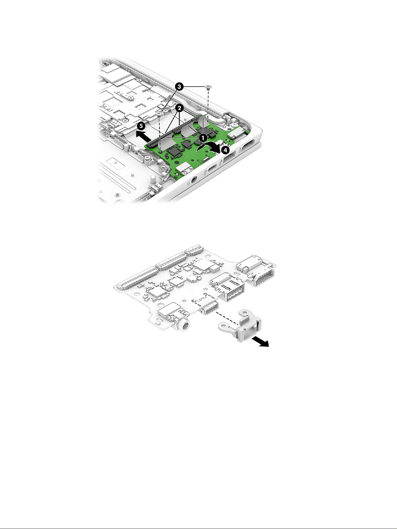
g. Lift the inside of the board (4) up, and then pull the board (5) into the computer to remove it.
h. Pull the USB bracket off the board. Be sure to install the bracket on the replacement board.
2. To remove the small I/O board:
a. Lift (do not remove) the tape (1) from the connector on the board.
b. Disconnect the cable from the ZIF connector (2) on the board.
c. Remove the two Phillips M2.0 × 2.5 screws (3) from the bracket on the board, and then remove
the bracket (4).
I/O boards
39
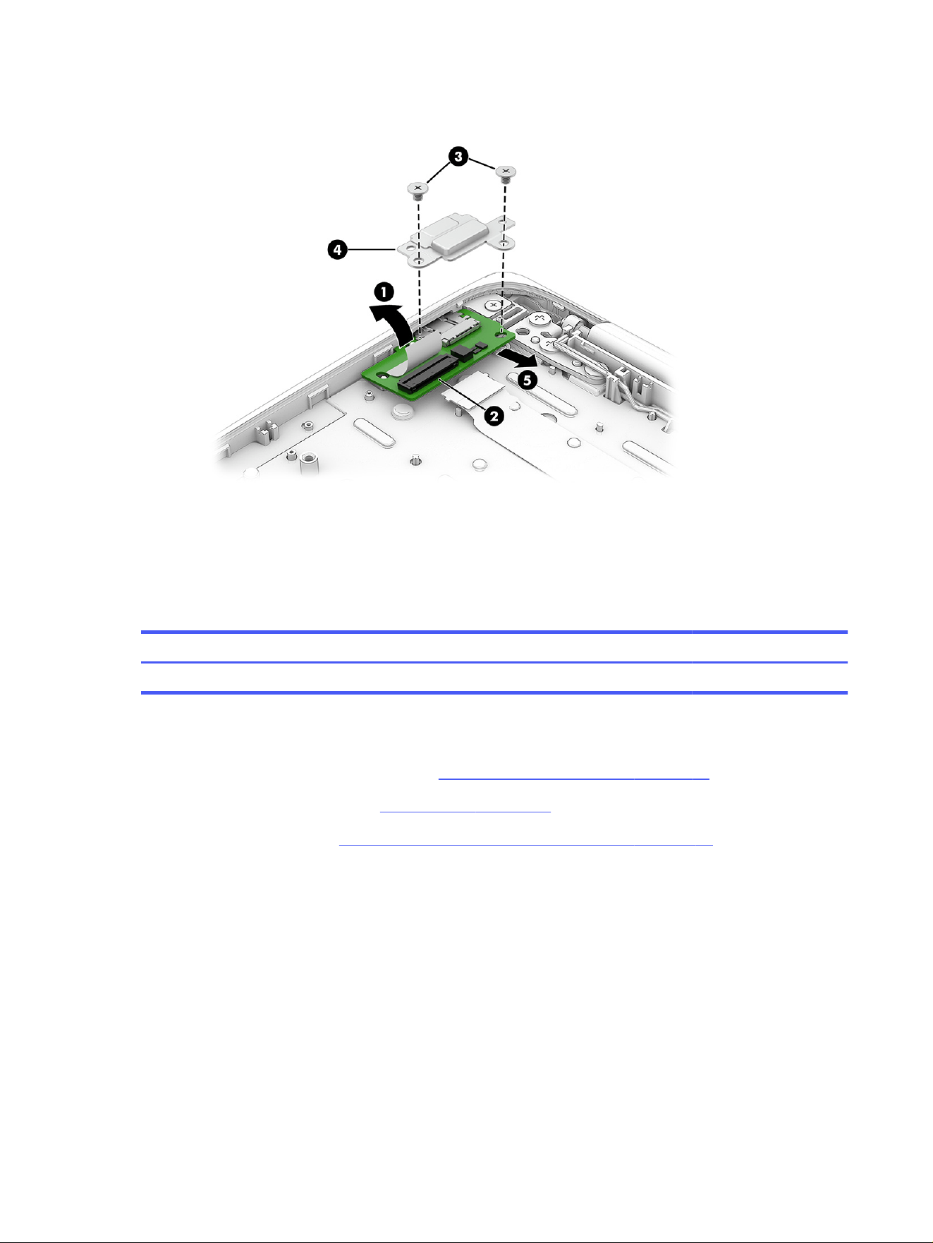
d. Lift the inside of the board up, and then pull the board (5) into the computer to remove it.
To install the I/O boards, reverse this procedure.
Heat sink
To remove the heat sink, use these procedures and illustrations.
Table 6-6
Heat sink description and part number
Description Spare part number
Heat sink (includes replacement thermal material) P22934-001
Before removing the heat sink, follow these steps:
1. Prepare the computer for disassembly (Preparation for disassembly on page 25).
2. Remove the bottom cover (see Bottom cover on page 32).
3. Remove the battery (see Removing and reinstalling the same battery on page 26).
Remove the heat sink:
1. Remove the five Phillips M2.0 × 3.5 screws (1) that secure the heat sink to the system board.
40
Chapter 6 Removal and replacement procedures for authorized service provider parts
2. Remove the heat sink (2).
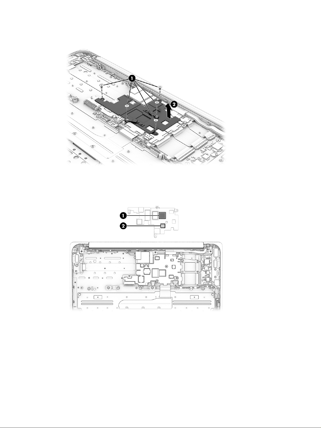
3. Each time the heat sink is removed, thoroughly clean and replace the gray (1) and white (2) thermal
material from the surface of the heat sink. Replacement thermal material is included with the heat
sink and system board spare part kits.
Reverse this procedure to install the heat sink.
System board
To remove the system board, use these procedures and illustrations.
System board
41

Table 6-7 System board descriptions and part numbers
Description Spare part number
System board (includes the processor, replacement thermal material, and the Chrome operating
system)
MediaTek MT8186 processor, 8 GB system memory, 64 GB eMMC memory P24052-001
MediaTek MT8186 processor, 8 GB system memory, 32 GB eMMC memory P24051-001
MediaTek MT8186 processor, 4 GB system memory, 64 GB eMMC memory P24050-001
MediaTek MT8186 processor, 4 GB system memory, 32 GB eMMC memory P24049-001
Before removing the system board, follow these steps:
1. Prepare the computer for disassembly (Preparation for disassembly on page 25).
2. Remove the bottom cover (see Bottom cover on page 32).
3. Remove the battery (see Removing and reinstalling the same battery on page 26).
4. Remove the WLAN module (see WLAN module on page 36).
Remove the system board:
1. Disconnect the following cables from the system board:
● Display cable (ZIF) (1)
● Large I/O board cable (ZIF) (2)
● Large I/O board cable (ZIF) (3)
● Large I/O board cable (ZIF) (4)
● Speaker cable (5)
● Keyboard cable (ZIF) (6)
● Touchpad cable (ZIF) (7)
● Small I/O board cable (ZIF) (8)
42
Chapter 6 Removal and replacement procedures for authorized service provider parts
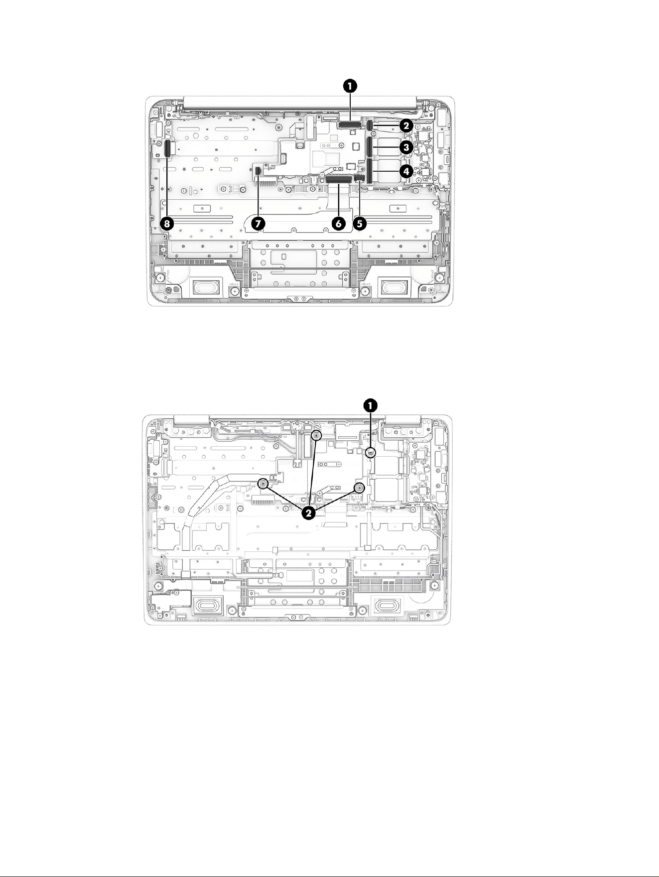
2. Remove the Phillips M2.0 × 2.0 screw (1) that secures the system board to the computer.
3. Remove three Phillips M2.0 × 3.5 screws (2) from the heat sink that secure the system board to the
computer. You do not have to remove the heat sink to remove the system board.
System board
43
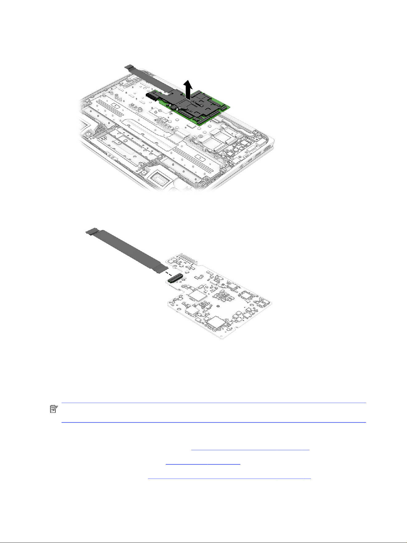
4. Lift the system board straight up to remove it from the computer.
5. Turn the system board upside down, and then disconnect the I/O board cable.
To install the system board, reverse this procedure.
Display assembly
To remove and disassemble the display assembly, use these procedures and illustrations.
NOTE: The display assembly is spared at the subcomponent level. For display assembly spare part
information, see the individual removal subsections.
Before removing the display panel, follow these steps:
1. Prepare the computer for disassembly (Preparation for disassembly on page 25).
2. Remove the bottom cover (see Bottom cover on page 32).
3. Remove the battery (see Removing and reinstalling the same battery on page 26).
44
Chapter 6 Removal and replacement procedures for authorized service provider parts
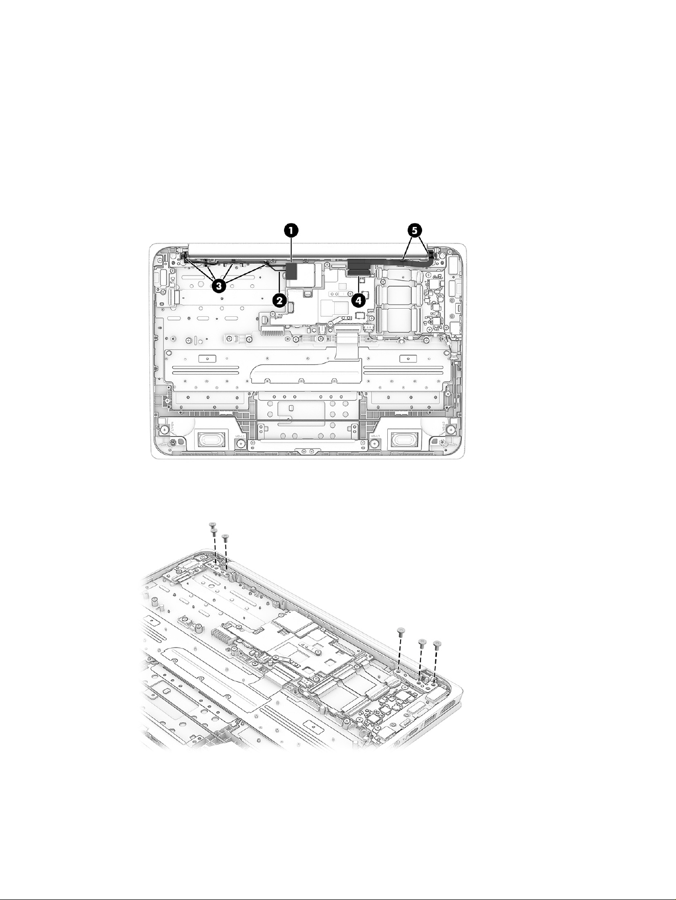
Remove the display assembly:
1. Remove the plastic antenna protector (1) from the WLAN module.
2. Disconnect the antenna cables (2) from the WLAN module.
3. Remove the antenna cables from the clips (3) along the top of the computer.
4. Disconnect the display cable (4) from the ZIF connector on the system board.
5. Remove the display cable from the clips (5) along the top of the computer.
6. Remove the six Phillips M2.5 × 3.5 screws that secure the display assembly to the computer.
Display assembly
45
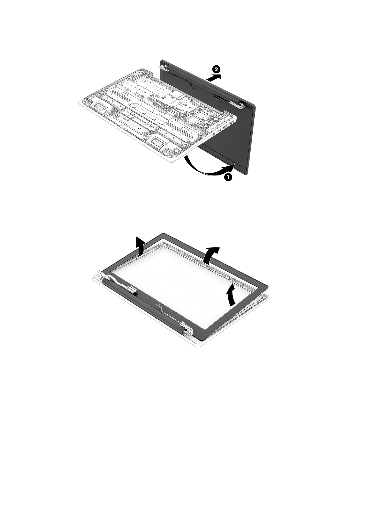
7. Open the display to 90° (1), and then separate the display (2) from the computer.
8. To remove the display panel from the display assembly:
a. Release the top, left, and right sides of the bezel from the display.
b. Rotate the hinges (1) until they are parallel with the display.
46
Chapter 6 Removal and replacement procedures for authorized service provider parts
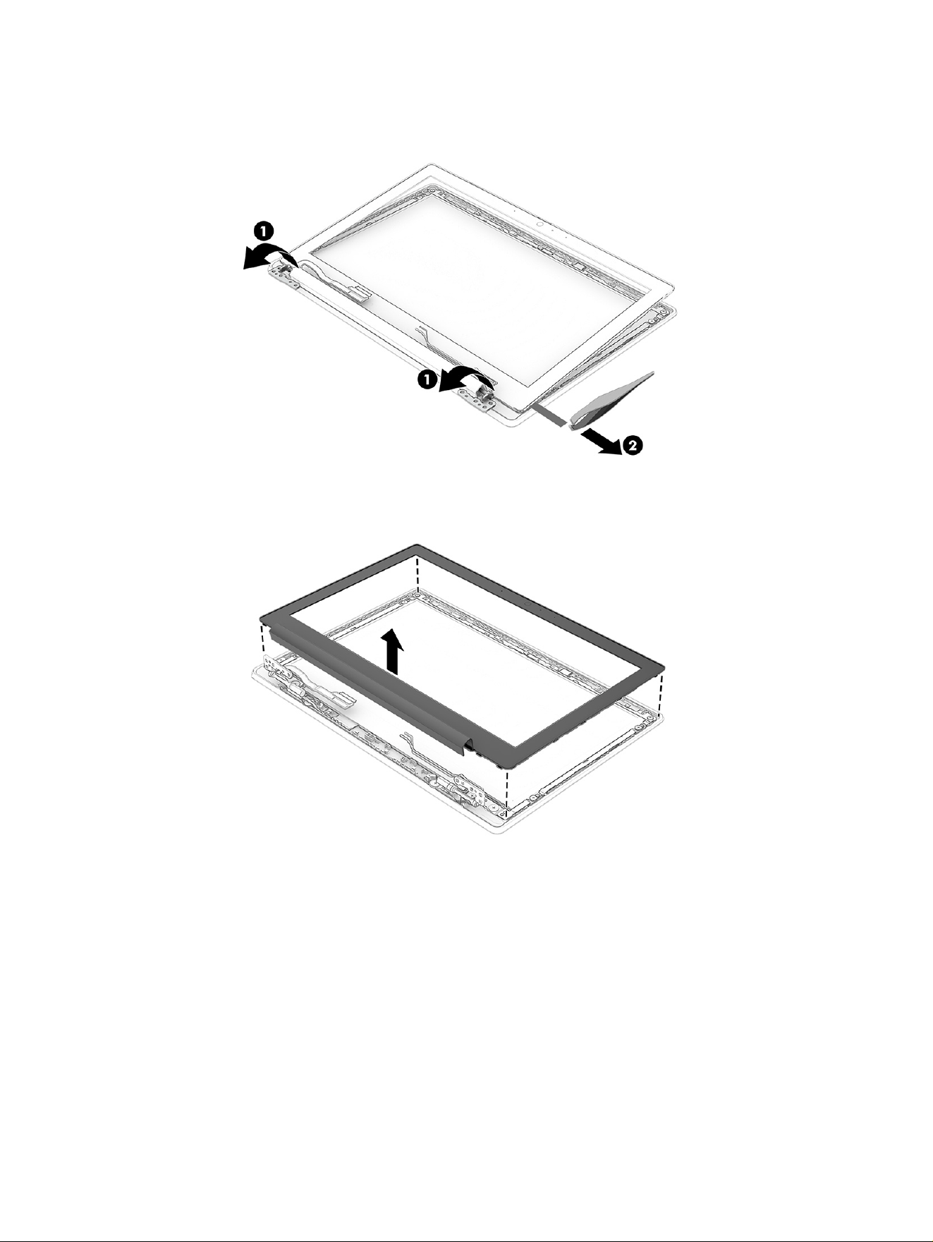
c. Insert tweezers or a pin tool into the adhesive hole, then twist and gently pull the tape (2) out
from under the bottom edge of the bezel.
d. Remove the bezel from the display panel.
The display bezel is available as spare part number P24063-001.
The bezel support kit is available in the Bracket Kit as spare part number P24054-001.
Display assembly
47
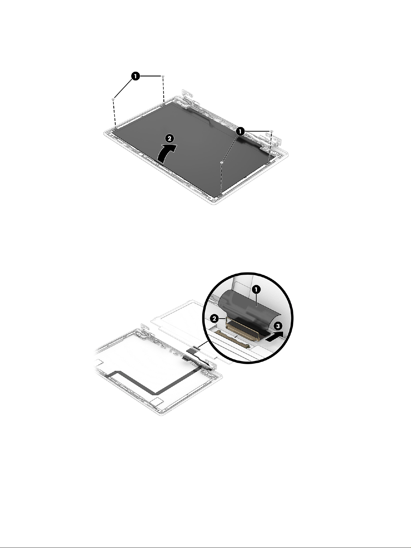
e. Remove the four Phillips M2.0 × 2.0 screws (1) that secure the display panel, and then lift the top
of the panel (2) up and over and place it next to the display rear cover.
f. Lift the conductive tape (1) from top of the connector on the back of the panel.
g. Lift the locking bar (2).
h. Disconnect the cable (3) from the display panel.
Display panels are available as the following spare part numbers:
P24060-001: SVA
P24061-001: UWVA
P24062-001: UWVA, touch screen
The display support bracket is available in the Bracket Kit as spare part number P24054-001.
48
Chapter 6 Removal and replacement procedures for authorized service provider parts
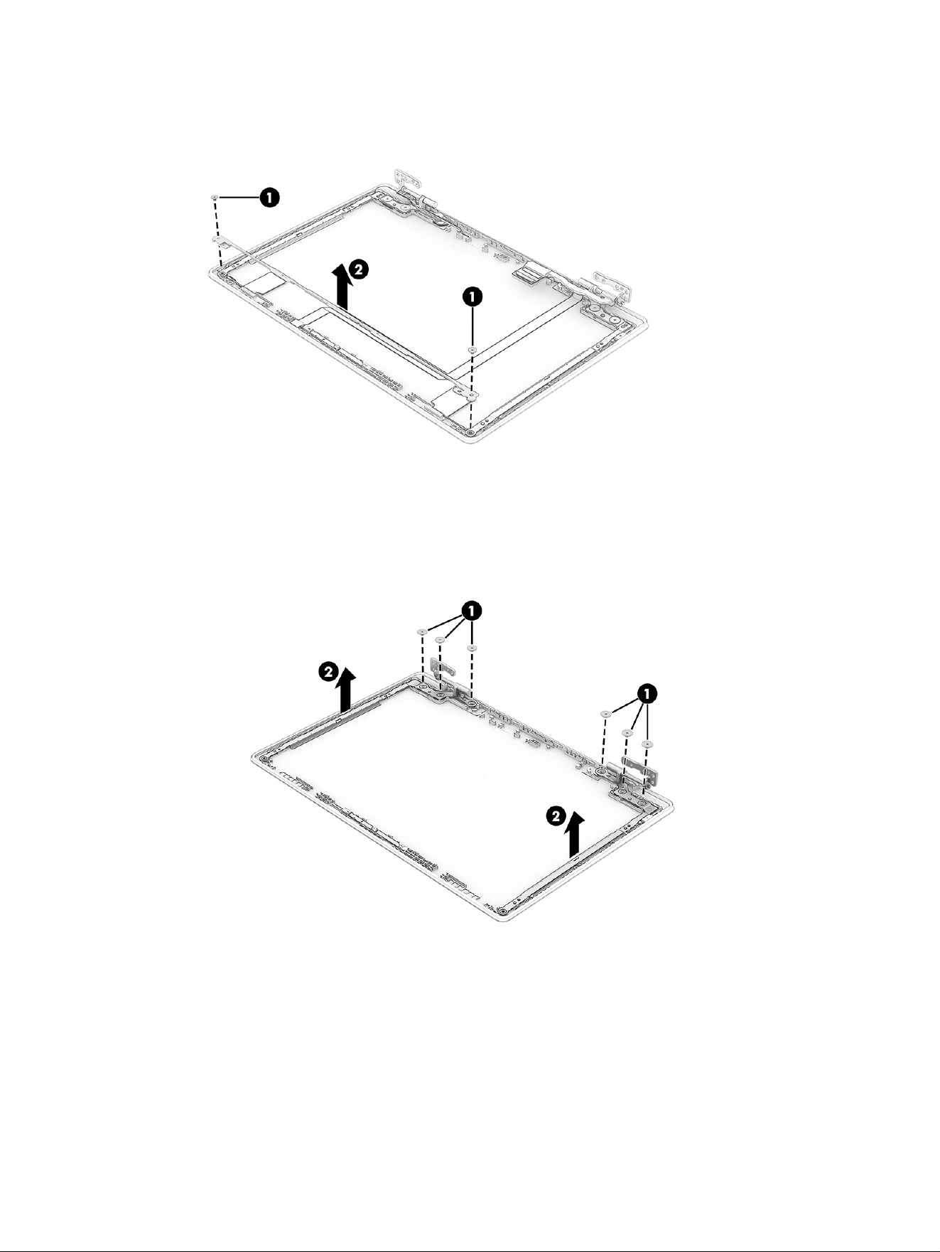
9. Remove the two Phillips M2.0 × 2.5 screws (1) from the top display bracket, and then remove the
bracket (2) from the display back cover.
10. To remove the hinges from the display rear cover:
a. Remove the three Phillips M2.5 × 2.5 broadhead screws (1) from each hinge.
b. Remove the hinges (2) from the display back cover.
The display hinges are available as spare part number P24066-001.
11. To remove the camera module:
a. Lift the cable (1) off the top of the connector on the camera module.
b. Disconnect the cable from the ZIF connector (2) on the module.
Display assembly
49
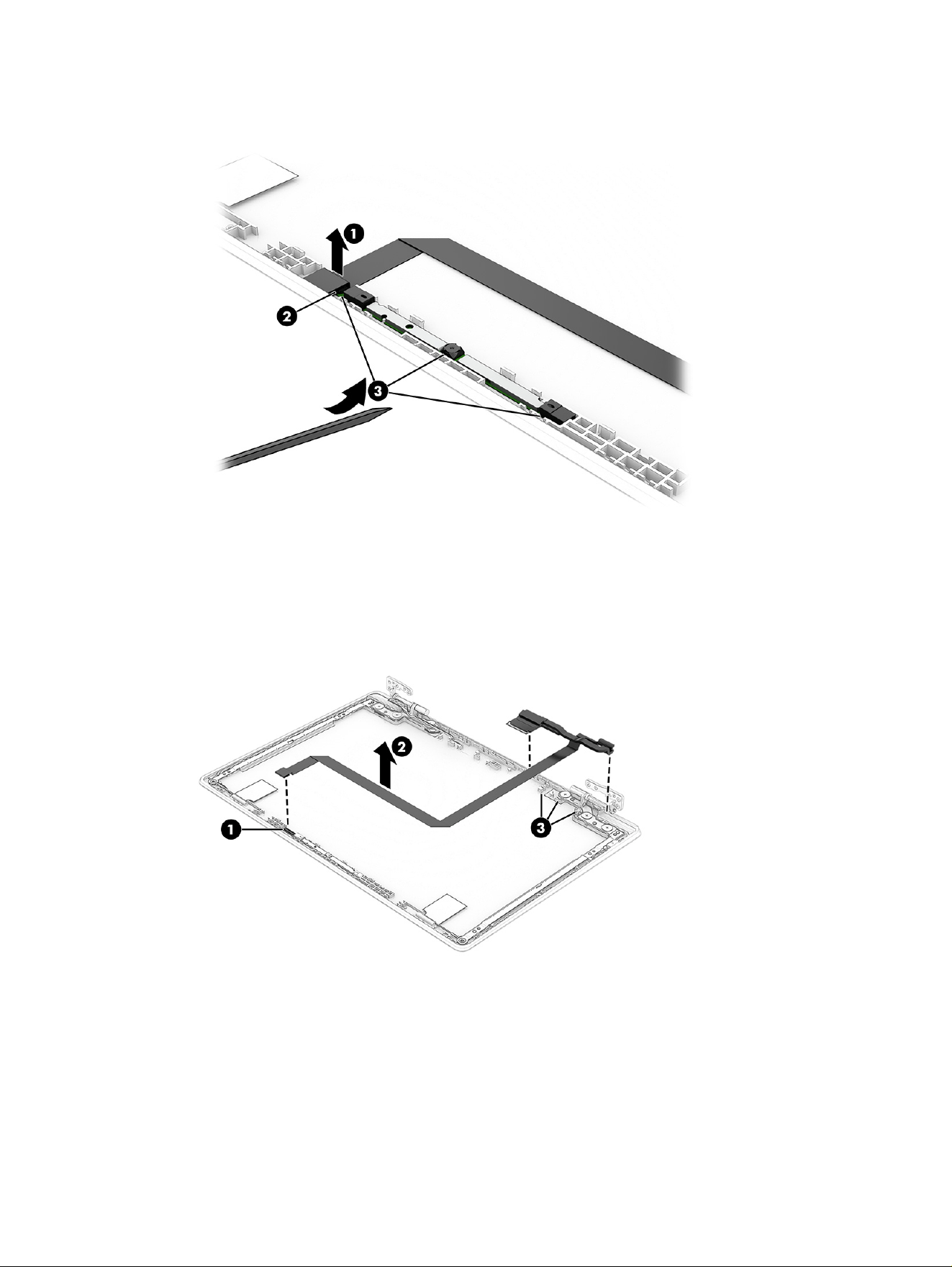
c. Insert a thin pry tool under the module, and then pull the tool along the entire module (3) to
release it.
The camera module is available as spare part number P24064-001.
12. To remove the display/camera cable, disconnect the cable from the ZIF connector (1) on the camera
module. Peel the cable (2) off the inside of the display rear cover, and then remove the cable from
the clips (3) along the bottom of the display rear cover.
The display cable is available as spare part number P24067-001.
50
Chapter 6 Removal and replacement procedures for authorized service provider parts
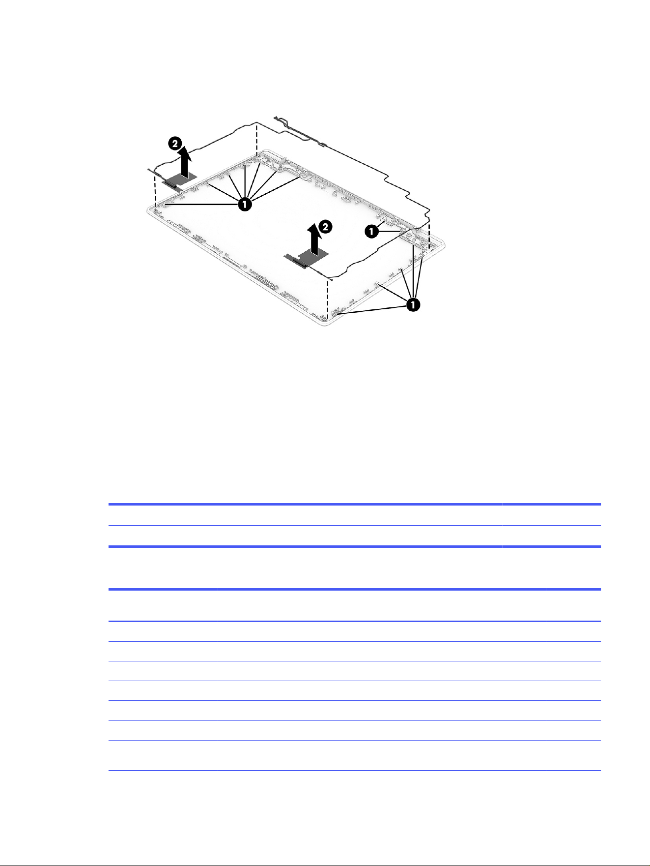
13. To remove the WLAN antennas and cables, release the cables from the clips (1) along the bottom
and sides on the display rear cover, and then peel the antennas (2) off the cover.
The WLAN wireless cables and antennas are available as spare part number P24065-001. The
wireless cables and antennas are also included in the display rear cover spare part kit.
To reassemble and replace the display assembly, reverse these procedures.
Top cover with keyboard
The top cover with keyboard remains after removing all other spare parts from the computer. The first
table provides the main spare part number for the top cover with keyboards. The second table provides
the keyboard country codes.
Table 6-8
Top cover with keyboard description and part number
Description Spare part number
Top cover with keyboard P24048-xx1
Table 6-9 Spare part country codes
For use in country or
region
Spare part
number
For use in country or
region
Spare part
number
For use in country or
region
Spare part
number
Belgium -A41 Hungary -211 Saudi Arabia -171
Brazil -201 Iceland -DD1 Slovenia -BA1
Bulgaria -261 India -D61 South Korea -AD1
Chile -161 Israel -BB1 Spain -071
Czech Republic/Slovakia -FL1 Italy -061 Switzerland -BG1
Denmark -081 Japan -291 Taiwan -AB1
Denmark, Finland, and
Norway
-DH1 The Netherlands -B31 Thailand -281
Top cover with keyboard 51

Table 6-9 Spare part country codes (continued)
For use in country or
region
Spare part
number
For use in country or
region
Spare part
number
For use in country or
region
Spare part
number
French Canada -DB1 Northern Africa -FP1 Turkey -141
Finland/Sweden -B71 Norway -091 Turkey-F -541
France -051 Portugal -131 Ukraine -BD1
Germany -041 Romania -271 United Kingdom -031
Greece -151 Russia -251 United States -001
52 Chapter 6 Removal and replacement procedures for authorized service provider parts

Backing up, resetting, and recovering7
This chapter provides information about the standard procedures of backing up your personal data,
resetting your computer to original factory conditions, and recovering your operating system.
Backing up
You can back up your data to an optional USB flash drive or SD memory card or through Google Drive™.
For detailed information about creating a backup, go to http://www.support.google.com.
Resetting
A factory reset erases the information on your computer hard drive, including files in the Downloads
folder. Before you reset, back up your files to an optional USB flash drive, to an SD memory card, or
through Google Drive. The factory reset will not delete your files at these locations.
You might want to reset your computer in the following circumstances:
● You see the message "Reset this Chrome device."
● You are having problems with your user profile or settings.
● You restarted your computer, and it still doesn’t work properly.
● You want to change the owner of your computer.
To reset your computer:
1. Under the Settings menu, select Advanced.
2. In the Powerwash section, select Powerwash.
3. Select Restart.
4. In the window that appears, select Powerwash, and then select Continue.
5. Follow the on-screen instructions to reset your computer, and sign in with your Google Account.
NOTE: The account you sign in with after you reset your computer is recognized as the owner
account.
6. After you complete the reset, you can set up your computer and check to see whether the problem
is fixed.
Recovering
When your ChromeOS doesn’t work properly, you can perform a recovery. A recovery reinstalls the
operating system, software programs, and original factory settings. It deletes locally saved files and
Backing up, resetting, and recovering
53

saved networks for all accounts. A system recovery does not affect Google Accounts and data synced
to Google Drive.
IMPORTANT: Recovery permanently erases everything on your computer hard drive, including your
downloaded files. If possible, back up your files before you recover your computer.
NOTE: For more information about performing a system recovery on your computer, go to
http://www.support.google.com.
Before you begin the recovery process, you need the following prerequisites:
● A USB flash drive or SD memory card with a capacity of 4 GB or greater. All data is erased from this
storage device when the recovery media is created, so back up all files from the device before you
begin.
● A computer with internet access. You must also have administrative rights to the computer.
● A computer AC adapter. The computer must be plugged into AC power during recovery.
● The “ChromeOS is missing or damaged” screen displaying on your computer. If this message is not
already displayed:
– Turn on the computer, press and hold the esc+f3 keys, and then press the power button. The
computer restarts, and the screen shows the “ChromeOS is missing or damaged” screen.
Option 1: Recovering using an internet connection
Use these instructions to recover the Chrome operating system on your computer without recovery
media:
1. Disconnect any external devices connected to your computer, plug in the power cord, and then turn
on the computer.
2. To enter recovery mode, press and hold the esc+f3 keys, and then press the power button. When
the “ChromeOS is missing or damaged” screen appears, select Recover using internet connection
and follow the on-screen instructions.
NOTE: The computer must have internet access.
3. When the “System Recovery is complete” message appears, reboot your computer.
The computer restarts with ChromeOS reinstalled.
Option 2: Installing the Chromebook Recovery Utility
The Chromebook Recovery Utility recovers the original operating system and software programs that
were installed at the factory. You can install this utility from the Chrome Web Store on any computer.
NOTE: Use this option if you do not have Internet access on your computer.
To install the Chromebook Recovery Utility:
■
Open the Chrome Web Store, search for chrome recovery, select Chromebook Recovery Utility
from the Apps list, and follow the on-screen instructions.
54
Chapter 7 Backing up, resetting, and recovering

Creating recovery media
You can use recovery media to recover the original operating system and software programs that were
installed at the factory.
To create recovery media:
1. Turn on a computer that has internet access.
NOTE: You must have administrative rights to the computer.
2. Select the Launcher icon, and then select All Apps.
3. In the Apps window, select Recovery, and then select Get started.
4. Follow the on-screen instructions to create the recovery media.
NOTE: All data and partitions on your recovery media will be deleted. Do not remove the USB flash
drive or SD memory card until the process is complete.
Recovering the Chrome operating system with recovery media
Use these instructions to recover the Chrome operating system on your computer using the recovery
media that you created.
1. Disconnect any external devices connected to your computer, plug in the power cord, and then turn
on the computer.
2. To enter recovery mode, press and hold esc+f3, and then press the power button. When the
“ChromeOS is missing or damaged” screen appears, insert the recovery media into your computer.
The recovery process begins immediately.
3. Wait while Chrome verifies the integrity of the recovery media.
NOTE: If you need to cancel the recovery during the verification process, press and hold the
power button until the computer turns off. Do not disrupt the system recovery process after the
verification step is complete.
NOTE: If an error message is displayed, you might need to run the Chrome Recovery Utility again
or use a different USB flash drive or SD memory card.
4. When the “System Recovery is complete” message appears, remove the recovery media.
The computer restarts with ChromeOS reinstalled.
Setting up your computer after a reset or recovery
After a reset or recovery is complete, perform the initial setup process.
For details about setting up the computer, go to http://www.support.google.com.
Creating recovery media
55

Erasing and reformatting the recovery media
When you create recovery media, the USB flash drive or SD memory card is formatted as a recovery
tool. After recovery, you must erase the recovery media to reuse your storage device. Follow these steps
to use the Chromebook Recovery Utility to erase the recovery media.
1. Select the Launcher icon, and then select All Apps.
2. In the apps window, select Recovery.
3. Select the Settings icon, and then select Erase recovery media.
4. Select the USB flash drive or SD memory card that you inserted, select Continue, and then select
Erase now.
5. After the recovery media is erased, select Done to close the Chromebook Recovery Utility, and then
remove the USB flash drive or SD memory card.
The media is ready to be formatted using a formatting tool provided by your operating system.
56
Chapter 7 Backing up, resetting, and recovering

Statement of memory volatility8
For general information regarding nonvolatile memory in HP business computers, and to restore
nonvolatile memory that can contain personal data after the system has been turned off and the hard
drive has been removed, use these instructions.
HP business computer products that use Intel®-based or AMD®-based system boards contain volatile
DDR memory. The amount of nonvolatile memory present in the system depends upon the system
configuration. Intel-based and AMD-based system boards contain nonvolatile memory subcomponents
as originally shipped from HP, with the following assumptions:
● No subsequent modifications were made to the system.
● No applications, features, or functionality were added to or installed on the system.
Following system shutdown and removal of all power sources from an HP business computer system,
personal data can remain on volatile system memory (DIMMs) for a finite period of time and also
remains in nonvolatile memory. Use the following steps to remove personal data from the computer,
including the nonvolatile memory found in Intel-based and AMD-based system boards.
NOTE: If your tablet has a keyboard base, connect to the keyboard base before beginning steps in this
chapter.
Current BIOS steps
Use these instructions to restore nonvolatile memory.
1. Follow these steps to restore the nonvolatile memory that can contain personal data. Restoring
or reprogramming nonvolatile memory that does not store personal data is neither necessary nor
recommended.
a. Turn on or restart the computer, and then quickly press esc.
NOTE: If the system has a BIOS administrator password, type the password at the prompt.
b. Select Main, select Apply Factory Defaults and Exit, and then select Yes to load defaults. The
computer restarts.
c. During the restart, press esc while the "Press the ESC key for Startup Menu" message is
displayed at the bottom of the screen.
NOTE: If the system has a BIOS administrator password, type the password at the prompt.
d. Select the Security menu, select Restore Security Settings to Factory Defaults, and then
select Yes to restore security level defaults. The computer restarts.
e. During the restart, press esc while the "Press the ESC key for Startup Menu" message is
displayed at the bottom of the screen.
NOTE: If the system has a BIOS administrator password, type the password at the prompt.
Statement of memory volatility
57

f. If an asset or ownership tag is set, select the Security menu and scroll down to the Utilities
menu. Select System IDs, and then select Asset Tracking Number. Clear the tag, and then
make the selection to return to the prior menu.
g. If a DriveLock password is set, select the Security menu, and scroll down to Hard Drive Utilities
under the Utilities menu. Select Hard Drive Utilities, select DriveLock, and then clear the check
box for DriveLock password on restart. Select OK to proceed.
h. Select the Main menu, and then select Reset BIOS Security to factory default. Select Yes at
the warning message. The computer restarts.
i. During the restart, press esc while the "Press the ESC key for Startup Menu" message is
displayed at the bottom of the screen.
NOTE: If the system has a BIOS administrator password, type the password at the prompt.
j. Select the Main menu, select Apply Factory Defaults and Exit, select Yes to save changes and
exit, and then select Shutdown.
k. Restart the system. If the system has a Trusted Platform Module (TPM), fingerprint reader, or
both, one or two prompts will appear—one to clear the TPM and the other to Reset Fingerprint
Sensor. Press or tap f1 to accept or f2 to reject.
l. Remove all power and system batteries for at least 24 hours.
2. Complete one of the following tasks:
● Remove and retain the storage drive.
● Clear the drive contents by using a third-party utility designed to erase data from an SSD.
● Clear the contents of the drive by using the following BIOS Setup Secure Erase command
option steps:
NOTE: If you clear data using Secure Erase, you cannot recover it.
a. Turn on or restart the computer, and then quickly press esc.
b. Select the Security menu and scroll down to the esc menu.
c. Select Hard Drive Utilities.
d. Finish by completing one of these tasks:
● Under Utilities, select Secure Erase, select the hard drive storing the data you want to
clear, and then follow the on-screen instructions to continue.
● Clear the contents of the drive using the following Disk Sanitizer commands steps:
i. Turn on or restart the computer, and then quickly press esc.
ii. Select the Security menu and scroll down to the Utilities menu.
iii. Select Hard Drive Utilities.
58
Chapter 8 Statement of memory volatility

iv. Under Utilities, select Disk Sanitizer, select the hard drive with the data that you want
to clear, and then follow the on-screen instructions to continue.
NOTE: The amount of time it takes for Disk Sanitizer to run can take several hours.
Plug the computer into an AC outlet before starting.
Nonvolatile memory usage
Use this table to troubleshoot nonvolatile memory usage.
Table 8-1 Troubleshooting information for nonvolatile memory usage
Description Volatility description Storage user data How to erase
Primary storage device, holds the
OS, applications, and application
settings
Nonvolatile, 8-256 GB of
eMMC or NVMe SSD storage,
removable
Yes
1
Follow instructions below
under “Erase the Primary
Storage Device”
System memory (RAM), holds
transient data during system
operation
Volatile, SODIMM socket.
Removable (4 GB/8 GB/16 GB)
Yes Unplug unit from power
Permanent system BIOS settings Nonvolatile; 16 KB; stored
No
2
Follow instructions below
under “Clearing BIOS
Settings”
System boot ROM (BIOS) Nonvolatile memory, 128 Mbit
(16 MB) socketed, removable
No Download the latest BIOS
for your model from the
HP website and follow the
instructions to flash the BIOS
that are on the website
RTC (CMOS) RAM Volatile memory, 256 bytes
located in AMD embedded
System on Chip (SoC)
No Desktop computers with a
CMOS button:
Unplug unit from main power,
remove top cover and press
the Clear CMOS button.
Notebook and desktop
computers without a CMOS
button:
1. Press and hold power
button for 12 seconds.
2. Press Windows key + V,
and then press power
button.
Keyboard/mouse (ROM) Nonvolatile, 2 KB embedded in
the super I/O controller (SIO2)
Yes N/A
Keyboard/mouse (RAM) Volatile, 256 bytes embedded in
the super I/O controller (SIO2)
No Unplug unit from main power
LOM EEPROM Nonvolatile, 2 MB embedded in
LAN controller
No N/A
Trusted Platform Module (TPM) Nonvolatile; 51 KB ROM for
firmware and 38 KB system
parametric data
No
3
Follow instructions below
under “Clearing TPM”
Nonvolatile memory usage 59

1
Under typical operation, the only user data stored on the primary storage device are preferences for
device configuration and settings for connections. However, the administrator can configure the system
to allow users to store data locally.
2
The only user data potentially stored in BIOS Settings are the ownership and asset tags, administrator
password, and startup password.
3
The Trusted Platform Module might contain encrypted passwords or certificates generated from user
or administrator input.
Questions and answers
Use this section to answer your questions about nonvolatile memory.
1. How can the BIOS settings be restored (returned to factory settings)?
IMPORTANT: The restore defaults feature does not securely erase any information on your hard
drive. See question and answer 6 for steps to securely erase information.
The restore defaults feature does not reset the Custom Secure Boot keys. See question and
answer 7 for information about resetting the keys.
a. Turn on or restart the computer, and then quickly press esc.
b. Select Main, and then select Apply Factory Defaults and Exit.
c. Follow the on-screen instructions.
d. Select Main, select Save Changes and Exit, and then follow the on-screen instructions.
2. What is a UEFI BIOS, and how is it different from a legacy BIOS?
The Unified Extensible Firmware Interface (UEFI) BIOS is an industry-standard software interface
between the platform firmware and an operating system (OS). It replaces the older BIOS
architecture but supports much of the legacy BIOS functionality.
Like the legacy BIOS, the UEFI BIOS provides an interface to display the system information and
configuration settings and to change the configuration of your computer before an OS is loaded.
BIOS provides a secure runtime environment that supports a GUI. In this environment, you can use
either a pointing device (touch screen, touchpad, pointing stick, or USB mouse) or the keyboard to
navigate and make menu and configuration selections. The UEFI BIOS also contains basic system
diagnostics.
The UEFI BIOS provides functionality beyond that of the legacy BIOS. In addition, the UEFI BIOS
works to initialize the computer’s hardware before loading and executing the OS; the runtime
environment allows the loading and execution of software programs from storage devices to
provide more functionality, such as advanced hardware diagnostics (with the ability to display more
detailed system information) and advanced firmware management and recovery software.
HP has provided options in Computer Setup BIOS to allow you to run in legacy BIOS, if required by
the operating system. Examples of this requirement would be if you upgrade or downgrade the OS.
3. Where is the UEFI BIOS located?
The UEFI BIOS is located on a flash memory chip. You must use a utility to write to the chip.
60
Chapter 8 Statement of memory volatility

4. What kind of configuration data is stored on the DIMM Serial Presence Detect (SPD) memory
module? How would this data be written?
The DIMM SPD memory contains information about the memory module, such as size, serial
number, data width, speed and timing, voltage, and thermal information. This information is written
by the module manufacturer and stored on an EEPROM. You cannot write to this EEPROM when the
memory module is installed in a computer. Third-party tools do exist that can write to the EEPROM
when the memory module is not installed in a computer. Various third-party tools are available to
read SPD memory.
5. What is meant by “Restore the nonvolatile memory found in Intel-based system boards”?
This message relates to clearing the Real Time Clock (RTC) CMOS memory that contains computer
configuration data.
6. How can the BIOS security be reset to factory defaults and erase the data?
IMPORTANT: Resetting results in the loss of information.
These steps do not reset Custom Secure Boot Keys. See question and answer 7 for information
about resetting the keys.
a. Turn on or restart the computer, and then quickly press esc.
b. Select Main, and then select Reset Security to Factory Defaults.
c. Follow the on-screen instructions.
d. Select Main, select Save Changes and Exit, and then follow the on-screen instructions.
7. How can the Custom Secure Boot Keys be reset?
Secure Boot is a feature to ensure that only authenticated code can start on a platform. If you
enabled Secure Boot and created Custom Secure Boot Keys, disabling Secure Boot does not clear
the keys. You must also select to clear the Custom Secure Boot Keys. Use the same Secure Boot
access procedure that you used to create the Custom Secure Boot Keys, but select to clear or
delete all Secure Boot Keys.
a. Turn on or restart the computer, and then quickly press esc.
b. Select the Security menu, select Secure Boot Configuration, and then follow the on-screen
instructions.
c. At the Secure Boot Configuration window, select Secure Boot, select Clear Secure Boot Keys,
and then follow the on-screen instructions to continue.
Using HP Sure Start (select products only)
Select computer models are configured with HP Sure Start, a technology that continuously monitors
your computer's BIOS for attacks or corruption.
If the BIOS becomes corrupted or is attacked, HP Sure Start restores the BIOS to its previously safe
state, without user intervention. Those select computer models ship with HP Sure Start configured and
enabled. HP Sure Start is configured and already enabled so that most users can use the HP Sure Start
default configuration. Advanced users can customize the default configuration.
To access the latest documentation on HP Sure Start, go to http://www.hp.com/support.
Using HP Sure Start (select products only)
61

Specifications9
This chapter provides specifications for your computer system.
Computer specifications
This section provides specifications for your computer. When traveling with your computer, the
computer dimensions and weights, input power ratings, and operating specifications provide helpful
information.
Table 9-1
Computer specifications
Metric U.S.
Dimensions
Width 293.0 mm 11.53 in
Depth 199.5 mm 7.85 in
Height (front) 8.97 mm 0.35 in
Height (rear) 15.79 mm 0.62 in
Weight 1.2 kg 2.65 lb
Input power
Operating voltage and current 5 V DC @ 2 A / 12 V DC @ 3 A /15 V DC @ 3 A – 45 W
USB-C
5 V DC @ 3 A / 9 V DC @ 3 A / 12 V DC @ 3.75 A /15 V DC
@ 3 A – 45 W USB-C
5 V DC @ 3 A / 9 V DC @ 3 A / 10 V DC @ 3.75 A / 12 V
DC @ 3.75 A / 15 V DC @ 3 A / 20 V DC @ 2.25 A – 45 W
USB-C
5 V DC @ 3 A / 9 V DC @ 3 A / 12 V DC @ 5 A / 15 V DC @
4.33 A / 20 V DC @ 3.25 A – 65 W USB-C
5 V DC @ 3 A / 9 V DC @ 3 A / 10 V DC @ 5 A / 12 V DC @
5 A / 15 V DC @ 4.33 A / 20 V DC @ 3.25 A – 65 W USB-C
Temperature
Operating 5°C to 35°C 41°F to 95°F
Nonoperating –20°C to 60°C –4°F to 140°F
Relative humidity (noncondensing)
Operating 10% to 90%
Nonoperating 5% to 95%
Maximum altitude (unpressurized)
Operating –15 m to 3,048 m –50 ft to 10,000 ft
62 Chapter 9 Specifications

Table 9-1 Computer specifications (continued)
Metric U.S.
Nonoperating –15 m to 12,192 m –50 ft to 40,000 ft
NOTE: Applicable product safety standards specify thermal limits for plastic surfaces. The device
operates well within this range of temperatures.
29.5 cm (11.6 in) display specifications
This section provides specifications for your display.
Table 9-2
Display specifications
Metric U.S.
Active diagonal size 29.5 cm 11.6 in
Resolution 1366 × 768 (HD)
Surface treatment Antiglare
Brightness 250 nits
Viewing angle SVA
UWVA
Backlight WLED
Display panel interface eDP
29.5 cm (11.6 in) display specifications 63

Power cord set requirements10
This chapter provides power cord requirements for countries and regions.
The wide-range input feature of the computer permits it to operate from any line voltage from 100 V AC
to 120 V AC, or from 220 V AC to 240 V AC.
The three-conductor power cord set included with the computer meets the requirements for use in the
country or region where the equipment is purchased.
Power cord sets for use in other countries or regions must meet the requirements of the country and
region where the computer is used.
Requirements for all countries
These power cord requirements are applicable to all countries and regions.
● The length of the power cord set must be at least 1.0 m (3.3 ft) and no more than 2.0 m (6.5 ft).
● All power cord sets must be approved by an acceptable accredited agency responsible for
evaluation in the country or region where the power cord set will be used.
● The power cord sets must have a minimum current capacity of 10 A and a nominal voltage rating of
125 V AC or 250 V AC, as required by the power system of each country or region.
● The appliance coupler must meet the mechanical configuration of an EN 60 320/IEC 320 Standard
Sheet C13 connector for mating with the appliance inlet on the back of the computer.
Requirements for specific countries and regions
To determine power cord requirements for specific countries and regions, use this table.
Table 10-1
Power cord requirements for specific countries and regions
Country/region Accredited agency Applicable note number
Argentina IRAM 1
Australia SAA 1
Austria OVE 1
Belgium CEBEC 1
Brazil ABNT 1
Canada CSA 2
Chile IMQ 1
Denmark DEMKO 1
Finland FIMKO 1
France UTE 1
64 Chapter 10 Power cord set requirements

Table 10-1 Power cord requirements for specific countries and regions (continued)
Country/region Accredited agency Applicable note number
Germany VDE 1
India BIS 1
Israel SII 1
Italy IMQ 1
Japan JIS 3
Netherlands KEMA 1
New Zealand SANZ 1
Norway NEMKO 1
People's Republic of China CCC 4
Saudi Arabia SASO 7
Singapore PSB 1
South Africa SABS 1
South Korea KTL 5
Sweden SEMKO 1
Switzerland SEV 1
Taiwan BSMI 6
Thailand TISI 1
United Kingdom ASTA 1
United States UL 2
1. The flexible cord must be Type HO5VV-F, three-conductor, 0.75 mm² conductor size. Power cord set
fittings (appliance coupler and wall plug) must bear the certification mark of the agency responsible
for evaluation in the country or region where it will be used.
2. The flexible cord must be Type SVT/SJT or equivalent, No. 18 AWG, three-conductor. The wall plug
must be a two-pole grounding type with a NEMA 5-15P (15 A, 125 V AC) or NEMA 6-15P (15 A, 250 V AC)
configuration. CSA or C-UL mark. UL file number must be on each element.
3. The appliance coupler, flexible cord, and wall plug must bear a T mark and registration number in
accordance with the Japanese Dentori Law. The flexible cord must be Type VCTF, three-conductor,
0.75 mm² or 1.25 mm² conductor size. The wall plug must be a two-pole grounding type with a
Japanese Industrial Standard C8303 (7 A, 125 V AC) configuration.
4. The flexible cord must be Type RVV, three-conductor, 0.75 mm² conductor size. Power cord set
fittings (appliance coupler and wall plug) must bear the CCC certification mark.
5. The flexible cord must be Type H05VV-F three-conductor, 0.75 mm² conductor size. KTL logo and
individual approval number must be on each element. Approval number and logo must be printed on
a flag label.
6. The flexible cord must be Type HVCTF three-conductor, 1.25 mm² conductor size. Power cord set
fittings (appliance coupler, cable, and wall plug) must bear the BSMI certification mark.
Requirements for specific countries and regions
65

7. For 127 V AC, the flexible cord must be Type SVT or SJT 3-conductor, 18 AWG, with plug NEMA 5-15P
(15 A, 125 V AC), with UL and CSA or C-UL marks. For 240 V AC, the flexible cord must be Type
H05VV-F three-conductor, 0.75 mm² or 1.00 mm² conductor size, with plug BS 1363/A with BSI or
ASTA marks.
66 Chapter 10 Power cord set requirements

Recycling11
When a nonrechargeable or rechargeable battery has reached the end of its useful life, do not dispose
of the battery in general household waste. Follow the local laws and regulations in your area for battery
disposal.
HP encourages customers to recycle used electronic hardware, HP original print cartridges,
and rechargeable batteries. For more information about recycling programs, see the HP website at
http://www.hp.com/recycle.
Recycling
67

Index
A
AC adapter light 4
AC adapter, spare part
numbers 13
action keys
identifying 6
audio-in (microphone) jack,
identifying 4
audio-out (headphone) jack,
identifying 4
audio, product description 1
B
backing up 53
battery
illustrated 11
light 4
removal and replacement 26
spare part number 11
spare part numbers 26
Bluetooth label 8
bottom cover
illustrated 11
removal 32
spare part number 11, 32
C
camera 5
identifying 5
illustrated 12
spare part numbers 12
camera light, identifying 5
camera privacy cover,
identifying 5
caring for your computer 20
cautions
electrostatic discharge 16, 17
Chromebook major
components 10
Chromebook Recovery Utility,
installing 54
cleaning your computer 20
caring for wood veneer 22
disinfecting 21
HP Easy Clean 20
removing dirt and debris 20
components
bottom 7
display 4
keyboard area 5
left side 3
right side 3
computer specifications 62
D
display
specifications 62, 63
display assembly
illustrated 11
subcomponents 11
display back cover
illustrated 13
spare part number 13
display bezel
illustrated 12
spare part numbers 12
display cable
illustrated 13
spare part number 13
display panel
illustrated 12
spare part numbers 12
E
electrostatic discharge (ESD) 16,
17
preventing damage 16-18
esc key, identifying 6
G
grounding methods 16-18
guidelines
packaging 16, 22
transporting 16, 22
workstation 16
H
hard drive
product description 1
specifications 62
HDMI port, identifying 4
headphone (audio-out) jack 4
heat sink
illustrated 11
removal 40
spare part number 11, 40
hinge
illustrated 13
spare part number 13
HP Sure Start 57, 61
I
I/I board
spare part number 38
I/O board
illustrated 11
removal 38
spare part number 11
illustrated parts catalog 10
internal microphones,
identifying 5
J
jacks
audio-in (microphone) 4
audio-out (headphone) 4
K
key
power 7
keyboard
product description 1
keyboard country codes 51
keys
esc 6
L
labels
Bluetooth 8
regulatory 8
serial number 8
service 8
wireless certification 8
WLAN 8
lights
AC adapter and battery 4
camera 5
68
Index

M
memory
nonvolatile 57
volatile 57
memory module
product description 1
microphone
product description 1
microphone (audio-in) jack,
identifying 4
model name 1
N
nonvolatile memory 57
O
operating system, product
description 2
P
packaging guidelines 16, 22
pointing device, product
description 1
ports
HDMI 4
product description 1
USB SuperSpeed 3, 4
USB Type-C SuperSpeed 4
power cord
requirements for all
countries 64
requirements for specific
countries and regions 64
set requirements 64
spare part numbers 13, 14
power key, identifying 7
power requirements, product
description 1
primary storage
product description 1
processor
product description 1
product description
audio 1
hard drive 1
keyboard 1
memory module 1
microphone 1
operating system 2
pointing device 1
ports 1
power requirements 1
primary storage 1
processors 1
product name 1
serviceability 2
solid-state drive 1
video 1
wireless 1
product name 1
product name and number,
computer 8
R
recovery media
creating 55
erase 56
recovery, performing 53
regulatory information
regulatory label 8
wireless certification labels 8
removal
speaker 33
removal and replacement
battery 26
procedures 25, 32
touchpad 34
removing personal data from
volatile system memory 57
resetting 53
S
security cable slot, identifying 3
serial number, computer 8
service labels, locating 8
serviceability, product
description 2
slots
security cable 3
solid-state drive
product description 1
spare part numbers
battery 26
camera 12
display assembly
components 11
display back cover 13
display bezel 12
display panel 12
hinges 13
speaker 33
touchpad 34
speaker
illustrated 11
removal 33
spare part number 11
spare part numbers 33
speakers, identifying 7
specifications
computer 62
display 62, 63
hard drive 62
static electricity 16, 17
support information 22
system board
illustrated 11
removal 41
spare part numbers 11, 41
system memory, removing
personal data from volatile 57
system recovery
Chrome operating system 55
Chromebook Recovery
Utility 54
internet connection 54
recovery media 55
T
top cover
illustrated 11
spare part number 11
top cover with keyboard
spare part numbers 51
touchpad
illustrated 11
removal and replacement 34
spare part number 11
spare part numbers 34
touchpad zone, identifying 6
transporting guidelines 16, 22
traveling with the computer 8
U
USB port, identifying 3, 4
USB Type-C port, identifying 4
V
video, product description 1
W
wireless certification label 8
wireless, product description 1
WLAN antennas, identifying 5
WLAN device 8
WLAN label 8
WLAN module
illustrated 11
removal 36
spare part number 11, 36
workstation guidelines 16
Index
69