ADA HEIGHT INSTALL GUIDE07/19/2022TEC_TM_120 | REV. C | EN FR
PRESERVE THE MOMENT
®
TRUE RESIDENTIAL
®
ADA HEIGHT
INSTALL GUIDE AND USER'S MANUAL

TRUE RESIDENTIAL
®
07/19/2022 TEC_TM_120 | REV. C | EN FR
THANK YOU
FOR YOUR PURCHASE

ADA HEIGHT INSTALL GUIDETEC_TM_120 | REV. C | EN FR 07/19/2022 Page 3 of 76
To ensure no part of the installation process has been overlooked, complete the checklist below.
☐ Have all packaging materials been removed?
☐ Are the anti-tip brackets securely installed and properly engaging the unit?
☐ Has the unit been properly leveled? Do all leveling legs touch the floor?
☐ Is the kickplate Installed?
☐ Is the doorstop being installed (if needed)?
☐ Does the customer understand the unit’s operation?
☐ Has the customer been given the key and literature package?
☐ Have all stainless steel surfaces been inspected for imperfections?*
☐ Is the unit operating correctly? If not, is the unit plugged in? Is the control turned on?
* To be completed by either an installer with the customer or an authorized True dealer upon
completion of installation. Stainless steel doors, handles, and shelves are covered by a
limited 30-day warranty for cosmetic defects.
INSTALLATION CHECKLIST

TRUE RESIDENTIAL
®
TEC_TM_120 | REV. C | EN FR07/19/2022Page 4 of 76
INSTALLATION CHECKLIST 3
SAFETY INFORMATION & OWNERSHIP
SAFETY WARNINGS & PRECAUTIONS 8
CORRECT DISPOSAL OF OLD REFRIGERATOR 9
OWNERSHIP 12
PRODUCT REGISTRATION 12
CONTACT INFORMATION 12
CABINET LOCATION & SPECIFICATIONS 13
NOTICE TO CUSTOMER 13
OUTDOOR USE 13
PRIOR TO INSTALLATION
ADA-COMPLIANT INSTALLATION
ROUGH OPENING & PLAN VIEWS
[32" (813 MM) OPENING] 16
OPTIONAL INSTALLATION
ROUGH OPENING & PLAN VIEWS
[34-1/2" (877 MM) OPENING] 21
CUSTOM OVERLAY PANEL SPECIFICATIONS 25
ELECTRICAL INSTALLATION & SAFETY 31
INSTALLATION
UNCRATING 34
ANTI-TIP BRACKET INSTALLATION 35
LEVELING LEGS 36
LEVELING 37
KICKPLATE INSTALLATION 37
CONTENTS

ADA HEIGHT INSTALL GUIDETEC_TM_120 | REV. C | EN FR 07/19/2022 Page 5 of 76
CONTENTS
CABINET SETUP
SHELF INSTALLATION 40
LOGO INSTALLATION 41
OPTIONAL LOCK INSTALLATION 42
DOOR OVERLAY PANEL INSTALLATION 44
DRAWER OVERLAY INSTALLATION 46
90° DOORSTOP INSTALLATION 48
CABINET OPERATION
CABINET COMPONENTS / ELECTRONIC
CONTROL & LIGHT SWITCH LOCATION 50
ELECTRONIC CONTROL OPERATION 53
MAINTENANCE CARE & CLEANING
CONDENSER COIL CLEANING 58
CONDENSATION 59
HANDLE TIGHTENING 59
STAINLESS STEEL CARE & CLEANING 60
ADJUSTMENTS, SERVICING &
REPLACING COMPONENTS
SERVICING & REPLACING COMPONENTS 64
REVERSING DOOR 65
DOOR ADJUSTMENT 66
DRAWER ADJUSTMENT 67
FREQUENTLY ASKED QUESTIONS 68
CONTACT US
CONTACT INFORMATION 70
WARRANTY
WARRANTY 71

TRUE RESIDENTIAL
®
TEC_TM_120 | REV. C | EN FR07/19/2022Page 6 of 76
NOTES

ADA HEIGHT INSTALL GUIDETEC_TM_120 | REV. C | EN FR 07/19/2022 Page 7 of 76
SAFETY WARNINGS & PRECAUTIONS
CORRECT DISPOSAL OF OLD REFRIGERATOR
OWNERSHIP
PRODUCT REGISTRATION
CONTACT US
CABINET LOCATION & SPECIFICATIONS
NOTICE TO CUSTOMER
OUTDOOR USE
PRESERVE THE MOMENT
®
SAFETY INFORMATION & OWNERSHIP
TRUE RESIDENTIAL
®
TEC_TM_120 | REV. C | EN FR07/19/2022Page 8 of 76
You have selected one of the finest commercial
refrigeration units made. It is manufactured under
strict quality controls with only the best quality
materials available. Your TRUE cooler, when properly
maintained, will give you many years of trouble-free
service.
WARNING – Use this appliance for its intended purpose
as described in this Installation Manual.
REFRIGERANT SAFETY & WARNING
INFORMATION
See the serial label inside the cabinet for the units
refrigeration type. For Hydrocarbon Refrigeration
(R290 only), see below:
DANGER – Risk of fire or explosion.
Flammable refrigerant used. DO NOT
use mechanical devices to defrost
refrigerator. DO NOT puncture refrigerant
tubing; follow handling instructions
carefully. To be repaired only by trained
service personnel.
DANGER – Risk of fire or explosion
(flammable refrigerant used), consult
repair manual/owner’s guide before
attempting to service this product. All
safety precautions must be followed.
Dispose of properly in accordance with
local and federal regulations. Follow all
safety precautions.
CAUTION – Keep all ventilation openings
clear of obstruction in the appliance
enclosure or in the structure housing the
appliance.
BASIC SAFETY & WARNING
PRECAUTIONS
• Take care during operation, maintenance or repairs
to avoid cuts or pinching from any part/component
of the cabinet.
• Units may pose a tipping hazard while uncrating,
during installation, or when moving the unit.
• Ensure the unit is properly installed and located in
accordance with the Installation Instructions before
use.
• This appliance is not to be used, cleaned or
maintained by persons (including children) with
reduced physical, sensory or mental capabilities or
lack of experience and knowledge, unless they have
been given supervision or instruction.
• DO NOT allow children to play with the appliance
or climb, stand, or hang on the unit’s shelves to
prevent damage to the refrigerator and personal
injury.
• DO NOT touch the cold surfaces in the freezer
compartment when hands are damp or wet. Skin
may stick to these extremely cold surfaces.
• Unplug the refrigerator before cleaning and making
repairs.
• Setting temperature controls to the 0 position or
powering off an electronic control may not remove
power from all components (e.g., light circuits,
perimeter heaters, and evaporator fans).
• DO NOT store or use gasoline, or other flammable
vapors and liquids, in the vicinity of this or any
other appliance.
HOW TO MAINTAIN YOUR TRUE REFRIGERATOR TO RECEIVE THE MOST
EFFICIENT AND SUCCESSFUL OPERATION
SAFETY INFORMATION & OWNERSHIP
ADA HEIGHT INSTALL GUIDETEC_TM_120 | REV. C | EN FR 07/19/2022 Page 9 of 76
• DO NOT store explosive substances such as aerosol
cans with a flammable propellant in this appliance.
• Keep fingers out of the "pinch point" areas;
clearances between the doors and cabinet are
necessarily small; be careful closing doors when
children are in the area.
• DO NOT use electrical appliances inside the food
storage compartments of the units unless the
appliances are of the type recommended by the
manufacturer.
NOTE: ALL SERVICING MUST BE
PERFORMED BY A QUALIFIED TECHNICIAN.
PROPER DISPOSAL OF THE CABINET
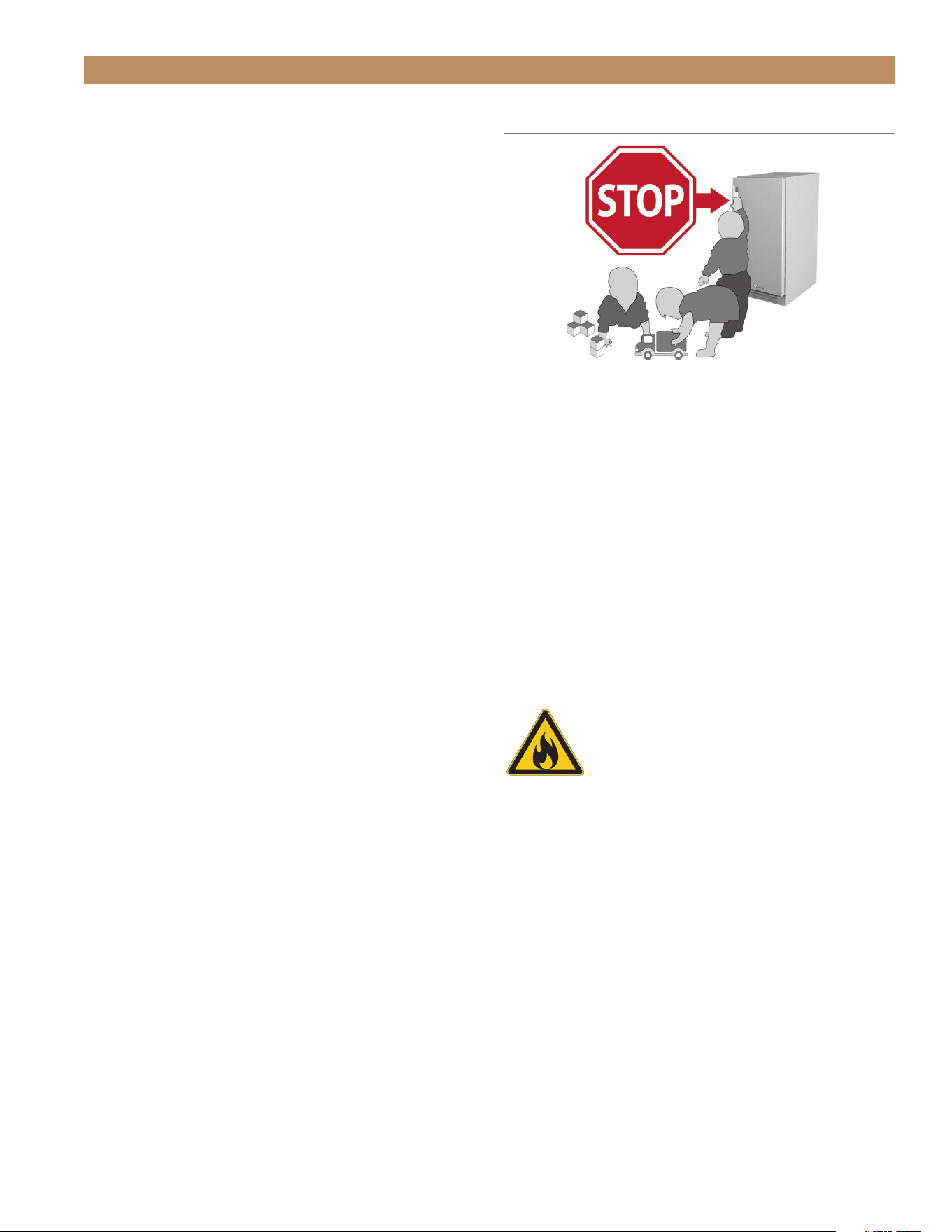
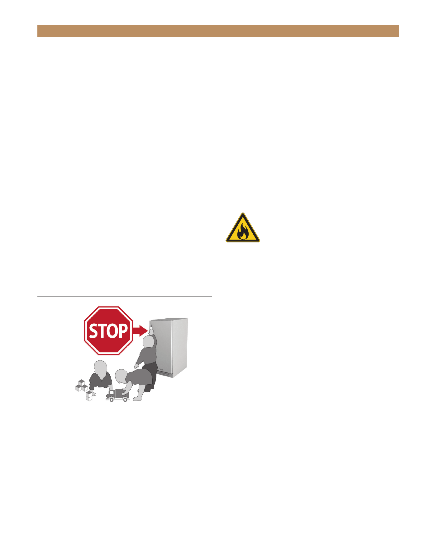
DANGER! RISK OF CHILD
ENTRAPMENT
Child entrapment and suffocation are not problems of
the past. Junked or abandoned refrigerators are still
dangerous, even if they will sit for "just a few days." If
you are getting rid of your old refrigerator, please follow
the instructions below to help prevent accidents.
Before throwing away your old refrigerator or freezer:
• Take off the doors.
• Leave the shelves in place so that children may not
easily climb inside.
DANGER – Risk of fire or explosion.
Flammable insulation and/or refrigerant
used. Dispose of all in accordance with
local and federal regulations. Follow all
safety precautions.
SAFETY INFORMATION & OWNERSHIP
TRUE RESIDENTIAL
®
TEC_TM_120 | REV. C | EN FR07/19/2022Page 10 of 76
Vous avez choisi l’un des meilleurs réfrigérateurs
commerciaux existants. Il a été fabriqué selon les
normes de qualité les plus exigeantes et avec les
meilleurs composants disponibles sur le marché. S’il
est correctement entretenu, votre réfrigérateur TRUE
vous offrira des années de fonctionnement sans souci.
AVERTISSEMENT – Utilisez cet appareil uniquement
pour l’usage prévu dans ce manuel d’utilisateur
INFORMATIONS DE SÉCURITÉ ET
D’AVERTISSEMENT CONCERNANT LE
FRIGORIGÈNE
Consultez l’étiquette de numéro de série à l’intérieur
de l’armoire pour connaître le type de réfrigération des
appareils. Pour une réfrigération aux hydricarbures
seulement (R290), voir ci-dessous
DANGER – Risque de feu ou d’explosion.
Le frigorigène utilisé est inflammable.
Ne PAS utiliser des appareils mécaniques
pour dégivrer le réfrigérateur.
Ne PAS percer les tuyaux de réfrigérant;
suivre scrupuleusement les instructions
de manutention. Les réparations doivent
être effectuées seulement par à un
technicien qualifié.
DANGER – Risque d’incendie ou
d’explosion (réfrigérant inflammable
utilisé), consultez le manuel de
réparation/guide d’utilisation avant
toute tentative d’intervention sur ce
produit. Toutes les mesures de sécurité
doivent être respectées. Mettez au
rebut conformément aux règlements
fédéraux ou locaux. Respectez toutes les
précautions de sécurité.
ATTENTION – Éviter toute obstruction des
ouvertures de ventilation dans la pièce
où l’armoire est située ou sur l’armoire
elle-même.
PRÉCAUTIONS DE BASE EN MATIÈRE
DE SÉCURITÉ ET AVERTISSEMENTS
• Lors de l’utilisation, de l’entretien ou des
réparations, il faut prendre soin d’éviter les
coupures et les pincements pouvant survenir
au contact des pièces ou des composantes de
l’armoire.
• Les appareils présentent un danger de basculement
pendant la sortie de la caisse, l’installation et lors
de leur déplacement.
• Assurez-vous que l’appareil est installé et positionné
correctement selon les Instructions d’installation
avant l’utilisation.
• Cet appareil n’est pas destiné à être utilisé, nettoyé
ou entretenu par des personnes (y compris des
enfants) aux capacités physiques, sensorielles ou
mentales réduites, ou manquant d’expérience ou
de connaissances, sauf sous supervision ou après
instruction concernant l’utilisation de l’appareil.
• NE PAS laisser les enfants jouer avec l’appareil ni
grimper, monter ni se suspendre aux clayettes de
l’appareil pour éviter des blessures comme des
dommages au réfrigérateur.
• NE TOUCHEZ PAS les surfaces froides dans le
compartiment du réfrigérateur avec les mains
humides ou mouillées. La peau peut coller à
ces surfaces extrêmement froides. La peau peut
adhérer à des surfaces extrêmement froides
• Débranchez le réfrigérateur avant de le nettoyer ou
d’effectuer des réparations.
• Le réglage des commandes de température en
position 0 ou la coupure par une commande
électronique peut ne pas couper l’alimentation
de tous les composants (par exemple: circuit
d’éclairage, chauffages périphériques, ventilateurs
d’évaporateur, etc.).
INFORMATIONS DE SÉCURITÉ ET PROPRIÉTÉ
COMMENT ENTRETENIR VOTRE RÉFRIGÉRATEUR TRUE POUR UN
FONCTIONNEMENT OPTIMAL ET PERFORMANT.
ADA HEIGHT INSTALL GUIDETEC_TM_120 | REV. C | EN FR 07/19/2022 Page 11 of 76
MISE AU REBUT CORRECTE DE
L’ARMOIRE
Les enfermements et étouffements d’enfant ne sont
pas des problèmes du passé. Les réfrigérateurs mis au
rebut ou abandonnés restent dangereux…même s’ils
ne sont mis là que pendant quelques jours. En cas de
mise au rebut de votre ancien réfrigérateur, suivre les
instructions ci-dessous pour éviter les accidents.
Avant de mettre au rebut votre ancien réfrigérateur ou
congélateur:
• Enlevez les portes.
• Laissez les étagères en place pour éviter que les
enfants puissent facilement grimper à l’intérieur.
DANGER – Risque de feu ou d’explosion.
Isolation et/ou réfrigérant inflammable
utilisé. Toujours mettre au rebut
conformément aux règlements fédéraux
ou locaux. Respectez toutes les
précautions de sécurité.
• NE STOCKEZ ni n’utilisez de l’essence ou un autre
produit volatile ou liquide inflammable à proximité
près de cet appareil ou de tout autre appareil.
• NE STOCKEZ PAS de substances explosives tels que
bombes aérosol à propulseur inflammable dans cet
appareil.
• Maintenez les doigts à distance des endroits
où vous pourriez vous pincer, les espaces entre
les portes et entre les portes et l’armoire sont
nécessairement très réduits. Faites attention en
fermant les portes quand des enfants se trouvent à
proximité.
• NE PAS utliser des appareils électriques à l’intérieur
des compartiments de stockage pour aliments
des appareils, à moins qu’ils ne soient d’un type
recommandé par le fabricant.
REMARQUE: TOUTES LES INTERVENTIONS
DOIVENT ÊTRE EFFECTUÉES PAR UN
TECHNICIEN QUALIFIÉ.
AVERTISSSEMENT DE MISE AU REBUT
DE L’ARMOIRE
DANGER! RISQUE DE
COINCEMENT POUR LES
ENFANTS
INFORMATIONS DE SÉCURITÉ ET PROPRIÉTÉ
TRUE RESIDENTIAL
®
TEC_TM_120 | REV. C | EN FR07/19/2022Page 12 of 76
OWNERSHIP
To ensure that your unit works properly from the
first day, it must be installed properly. We highly
recommend a trained refrigeration mechanic and
electrician install your True equipment. The cost of a
professional installation is money well spent.
Before you start to install your TRUE unit, carefully
inspect it for freight damage. IF DAMAGE IS DISCOVERED,
DO NOT INSTALL THE UNIT OR PUT IT IN SERVICE. Notify
True customer service, and immediately file a claim
with the delivery freight carrier.
TRUE is not responsible for damage incurred during
shipment.
SAFETY INFORMATION & OWNERSHIP
CONTACT INFORMATION
For any questions about installation, please contact your TRUE dealer or TRUE Residential Technical Service.
Please have your model and serial number (see serial label location below) available so we can better assist you
with your service- or parts-related inquiries.
CUSTOMER SERVICE
Phone: 888-616-8783
info@true-residential.com
TECHNICAL SERVICE DEPARTMENT
Phone: 844-746-9423
TrueResidentialService@truemfg.com
WARRANTY DEPARTMENT
Phone: 844-849-6179
TrueResidentialWarranty@truemfg.com
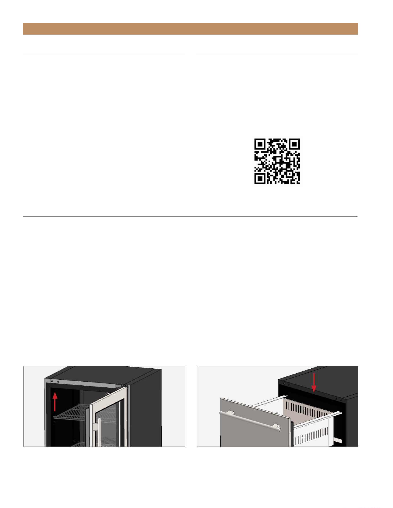
SERIAL LABEL LOCATION
Your serial label contains important information such as your model name and serial number. Label location varies
by model type.
FIG. 1.
Door units: upper left interior wall.
FIG. 2.
Drawer units: front center interior ceiling.
REGISTER YOUR PRODUCT
To qualify for TRUE’s extended 7–12 year parts
only sealed system warranty, you must register your
product* within 12 months of the unit’s installation
date. To register your unit, complete and submit the
form at www.true-residential.com/product-registration.
For warranty details, please see page 72.
* Please note that ice machines do not qualify for this
extended warranty.
ADA HEIGHT INSTALL GUIDETEC_TM_120 | REV. C | EN FR 07/19/2022 Page 13 of 76
SAFETY INFORMATION & OWNERSHIP
CABINET LOCATION &
SPECIFICATIONS
For more information regarding the installation location
or cabinet specifications, please see “Site Preparation”
starting on page 16.
• Appliance is NSF 7 approved.
• Appliance is UL rated for outdoor use.
• Appliance is not suitable for an area where a
pressure washer or hose may be used.
• Ensure the location will provide adequate
clearances and sufficient airflow for the cabinet.
• Ensure the power supply for the cabinet matches
the cabinet specification sheet or cabinet data plate
and is within the rated voltage (±5%) Also, ensure
the amperage rating of the circuit is correct and the
circuit is properly grounded.
• The cabinet should always be plugged into its own
individual dedicated electrical circuit. The use of
adapter plugs and extension cords is prohibited.
NOTICE TO CUSTOMER
Loss or spoilage of products in
your refrigerator/freezer is not
covered by warranty. In addition
to following recommended
installation procedures, run the
refrigerator/freezer for 24 hours
prior to usage to verify its proper operation.
OUTDOOR USE
All True undercounter units are rated for outdoor use.
• In regions with high dewpoints or humidity,
condensation may appear on the glass and around
gasket seals. For best operation, keep the unit fully
stocked with product.
• In areas where the ambient temperature regularly
exceeds 95°F (35°C), vent the rear of the rough
opening for optimum performance. Recommended
vent size is 4" x 10" (102 mm x 254 mm).
• For the best operation, install your True unit with
your outdoor bar/kitchen countertop covering the
door or drawer gasket (flush install). The rough
opening should be at least 24" (606 mm) deep.
NOTE: DOOR AND DRAWER GASKETS DO NOT
PROVIDE A WATERTIGHT SEAL AGAINST THE
ELEMENTS.
When the temperature consistently reaches 32°F (0°C)
or below, winterize your unit. Remove all product from
the unit, unplug or turn the unit off, and place a cover
over the unit.

TRUE RESIDENTIAL
®
TEC_TM_120 | REV. C | EN FR07/19/2022Page 14 of 76
NOTES

ADA HEIGHT INSTALL GUIDETEC_TM_120 | REV. C | EN FR 07/19/2022 Page 15 of 76
PRIOR TO INSTALLATION
ADA-COMPLIANT INSTALLATION
ROUGH OPENING & PLAN VIEWS
[32" (813 mm) OPENING]
OPTIONAL INSTALLATION
ROUGH OPENING & PLAN VIEWS
[34-1/2" (877 mm) OPENING]
CUSTOM OVERLAY PANEL SPECIFICATIONS
ELECTRICAL INSTALLATION & SAFETY
PRESERVE THE MOMENT
®
TRUE RESIDENTIAL
®
TEC_TM_120 | REV. C | EN FR07/19/2022Page 16 of 76
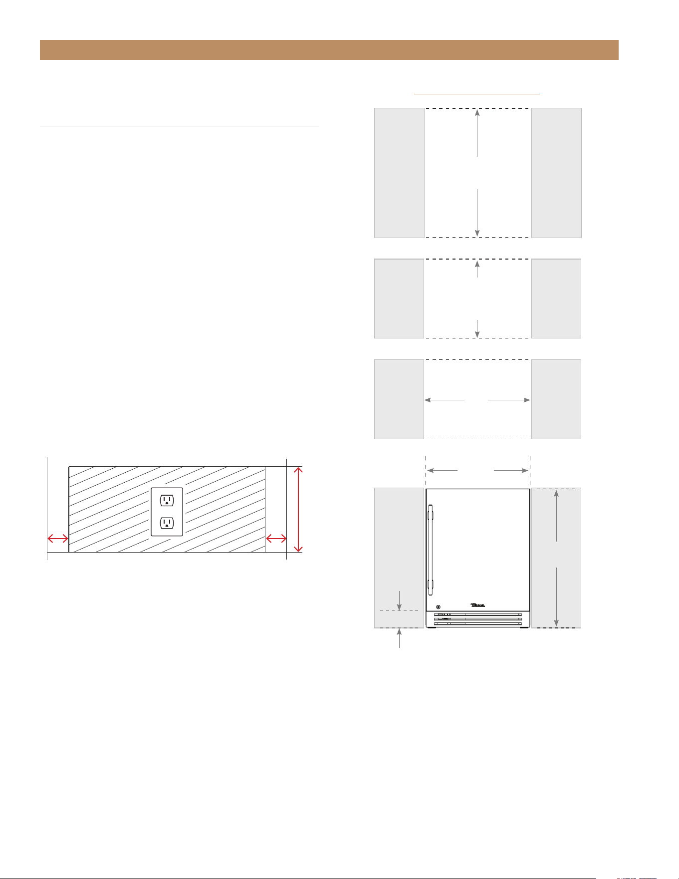
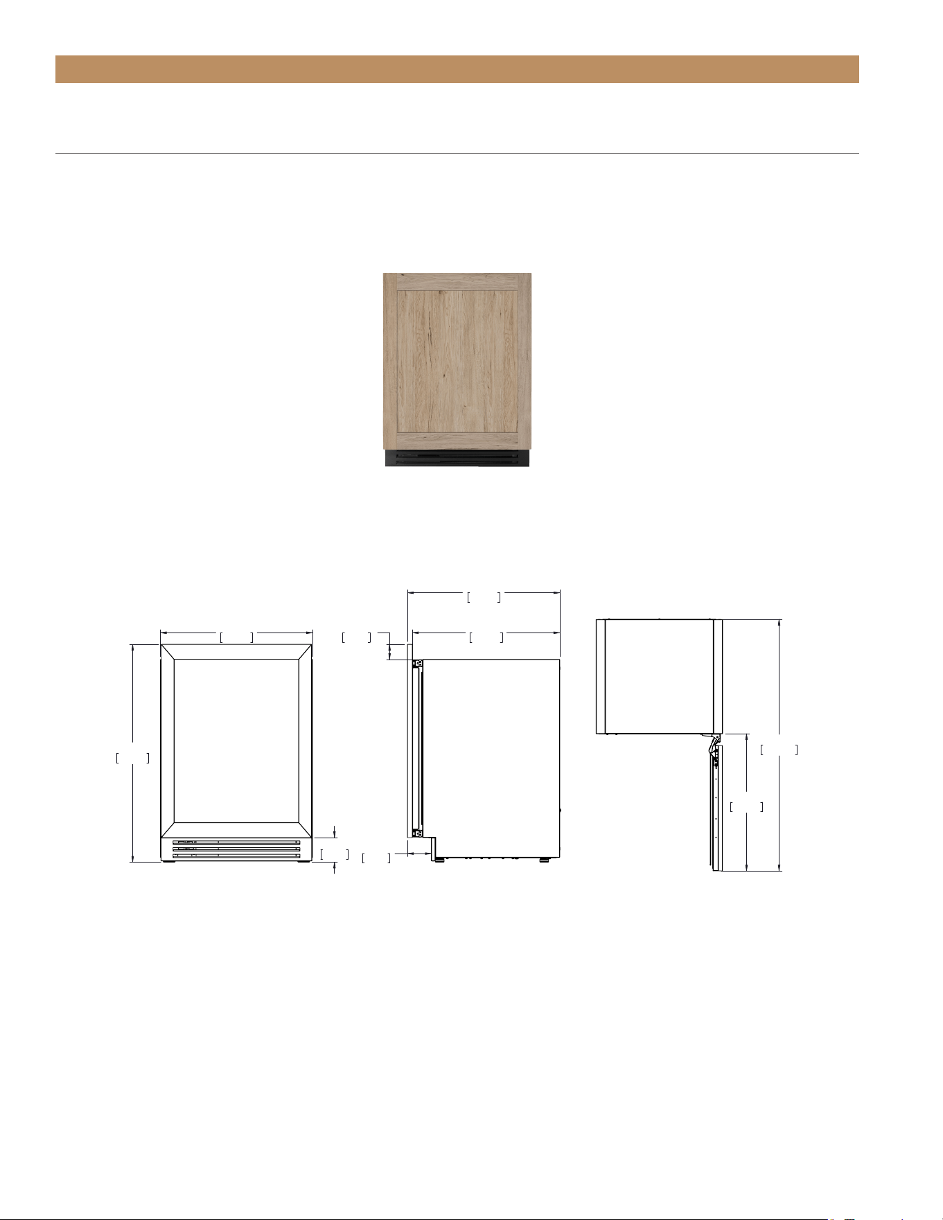
PRIOR TO INSTALLATION
HEIGHT
32" (813 mm)
DEPTH
24"
(610 mm)
WIDTH
24"
(610 mm)
23-7/8"
(606 mm)
31-7/8"
(810 mm)
3-7/8"
(98.4 mm)
ADA ROUGH OPENING
Front view
of unit
between
cabinets
ADA-COMPLIANT INSTALLATION
ROUGH OPENING & PLAN VIEWS
[32" (813 mm) OPENING]
The ADA-compliant installation consists of the ADA
unit, standard leveling legs, and 4" (102 mm) kickplate.
This installation fits beneath an ADA-compliant
countertop. For the rough opening and cabinet
specifications of alternate installation configurations,
please see “Optional Installation Rough Openings &
Plan Views” starting on page 21.
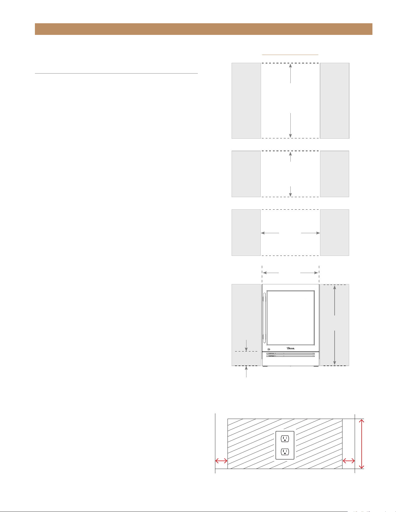
ADA-COMPLIANT ROUGH OPENING
Please see the recommended dimensions for a ADA-
compliant rough opening below. For unit specifications,
please see “ADA-Compliant Installation Plan Views”
starting on page 16.
CUTOUT OPENINGS
To minimize the depth of the cutout opening, the
electrical outlet must be positioned as shown below.
Outlet must be flush with the wall.
ANTI-SWEAT FOAM END PANELS
When installing two or more True units side-by-side,
be sure to leave at least 5/8" (16 mm) gap between the
cabinets, or install foam pads between the cabinets
and on any side without this gap, to prevent moisture
from developing on applications.
If installing anti-sweat foam end panels, True
recommends applying a panel to each of the
units being joined together. To order foam pads,
contact our parts department at 844-849-6226 or
TrueResidentialParts@TrueMfg.com.
2"
(51 mm)
2"
(51 mm)
Rear wall of cut out
8"
(203 mm)
ADA HEIGHT INSTALL GUIDETEC_TM_120 | REV. C | EN FR 07/19/2022 Page 17 of 76
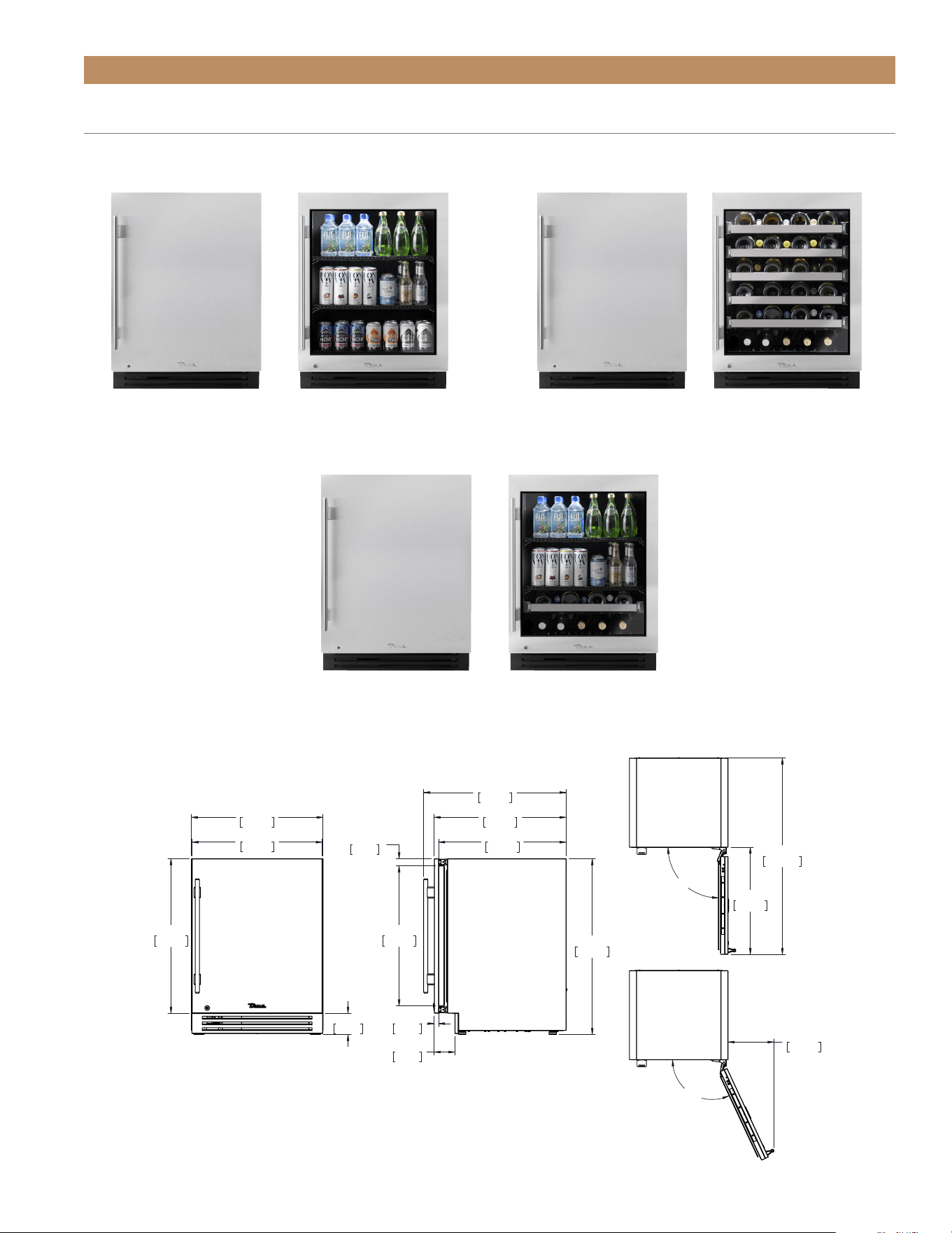
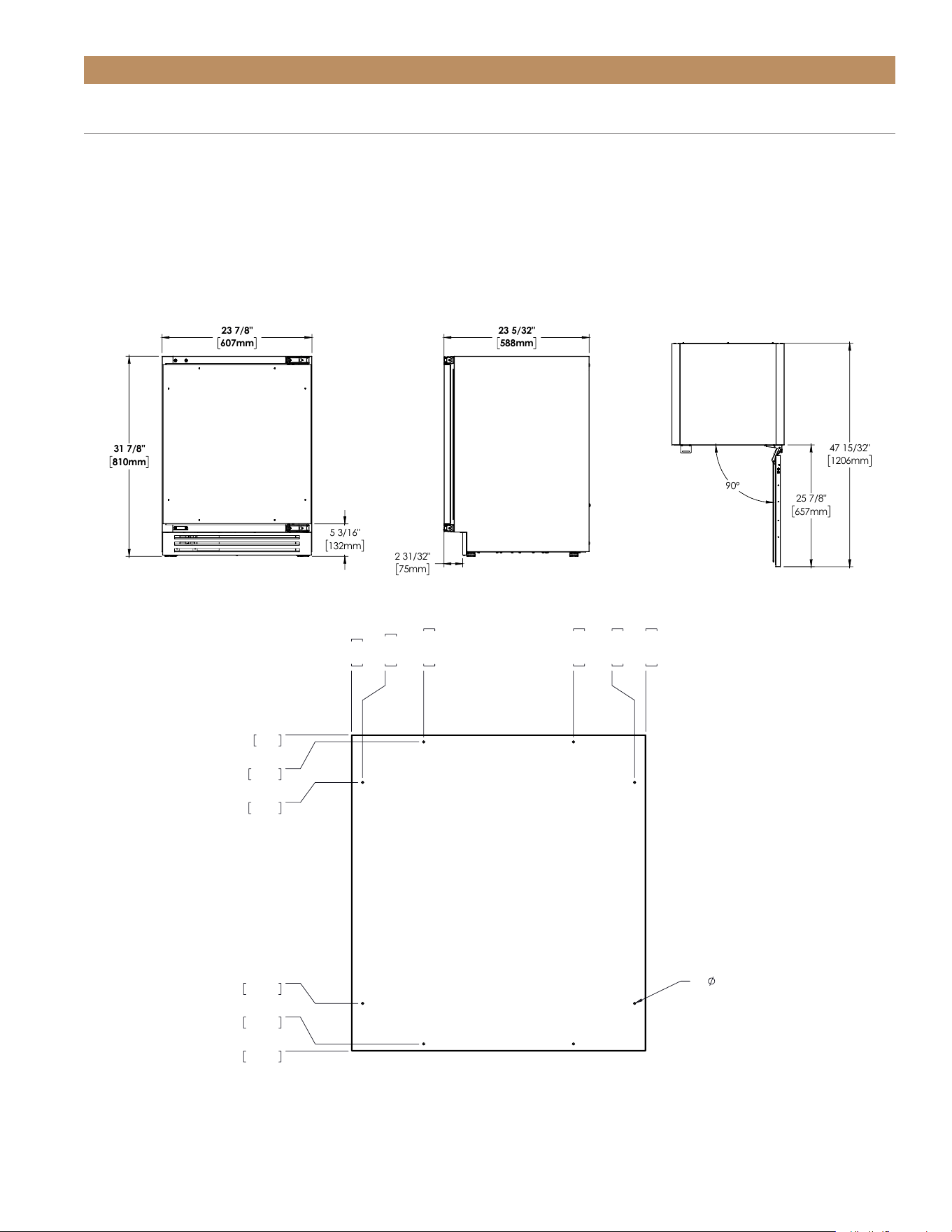
ADA-COMPLIANT INSTALLATION PLAN VIEWS
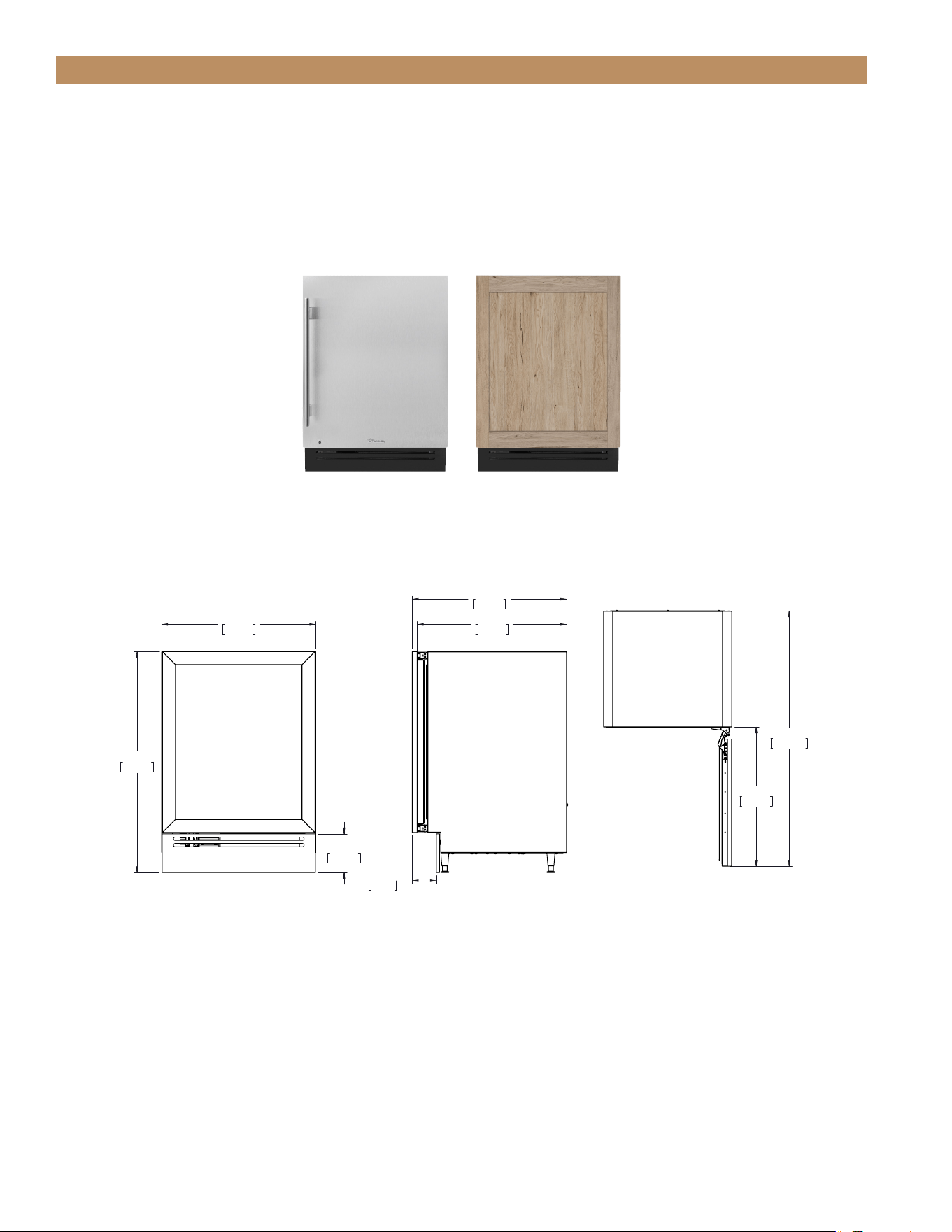
PLAN VIEW DIMENSIONS
23 7/8"
607mm
23 5/8"
600mm
3 7/8"
99mm
28"
711mm
3 3/4"
95mm
23 5/32"
588mm
23 15/16"
608mm
25/32"
20mm
1 5/16"
33mm
25 3/8"
645mm
31 7/8"
810mm
25 27/32"
657mm
90°
47 15/32"
1206mm
25 7/8"
657mm
115°
11 3/32"
282mm
TURADA-24-RS-A~S
09/24/20
REFRIGERATORS
BEVERAGE CENTERS
STAINLESS SOLID & FRAMED GLASS DOOR UNITS
Dimensions may vary by ± 1/8" (3.2 mm)
WINE CABINET
TUWADA-24-R/L-RG-A~STUWADA-24-R/L-RS-A~STURADA-24-R/L-RG-A~S
TUBA DA-24-R/L-RG-A ~S
TURADA-24-R/L-RS-A~S
TUBA DA-24-R/L-RS-A~S
TRUE RESIDENTIAL
®
TEC_TM_120 | REV. C | EN FR07/19/2022Page 18 of 76
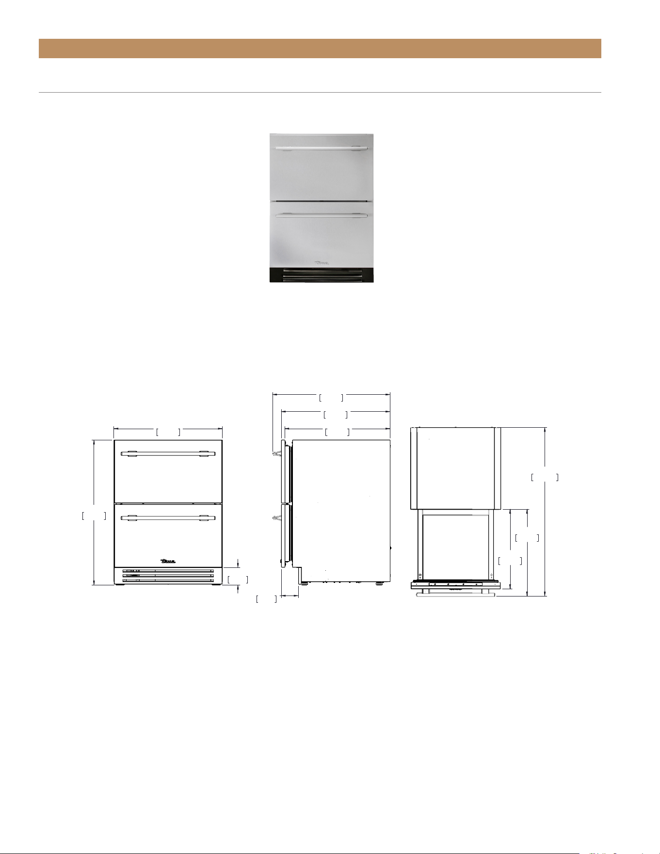
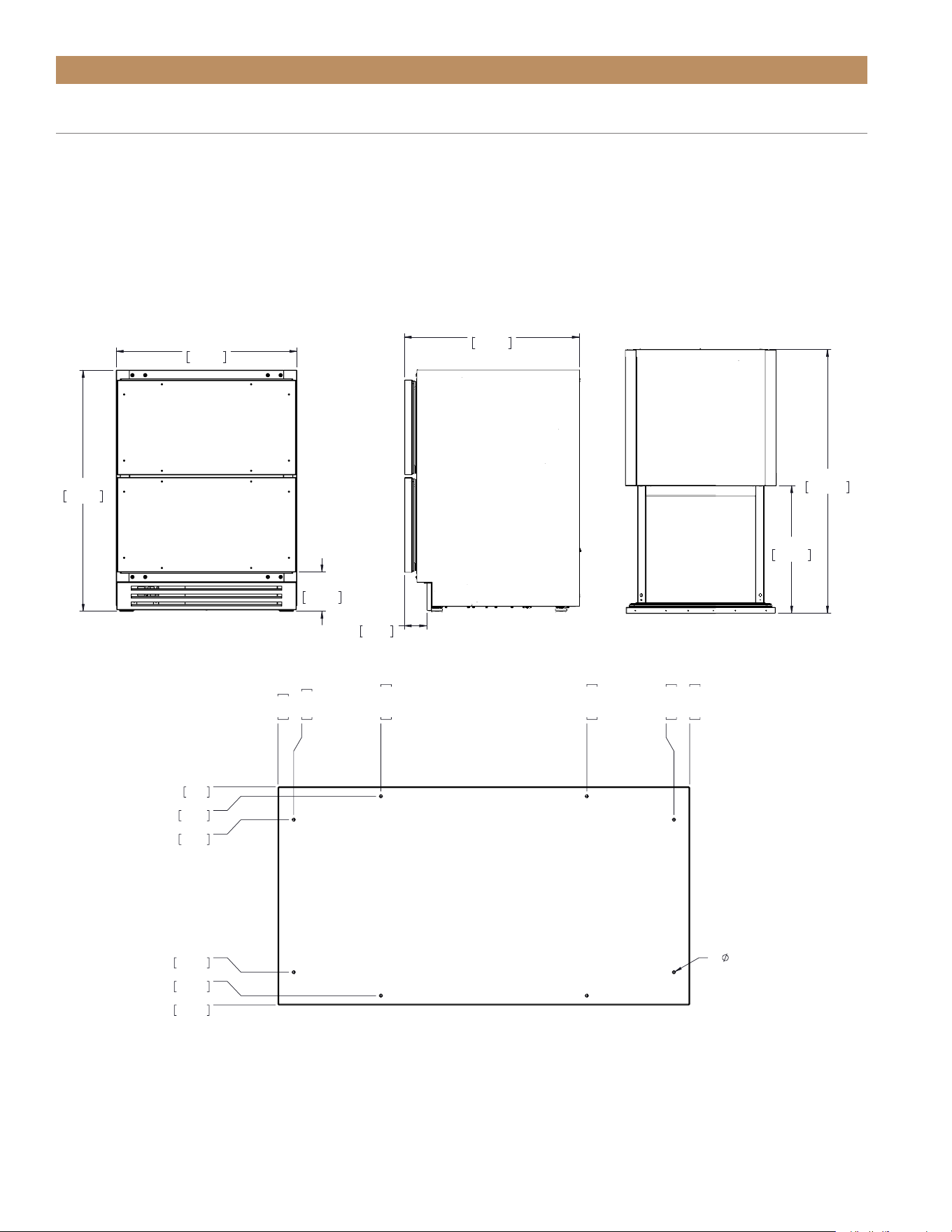
ADA-COMPLIANT INSTALLATION PLAN VIEWS
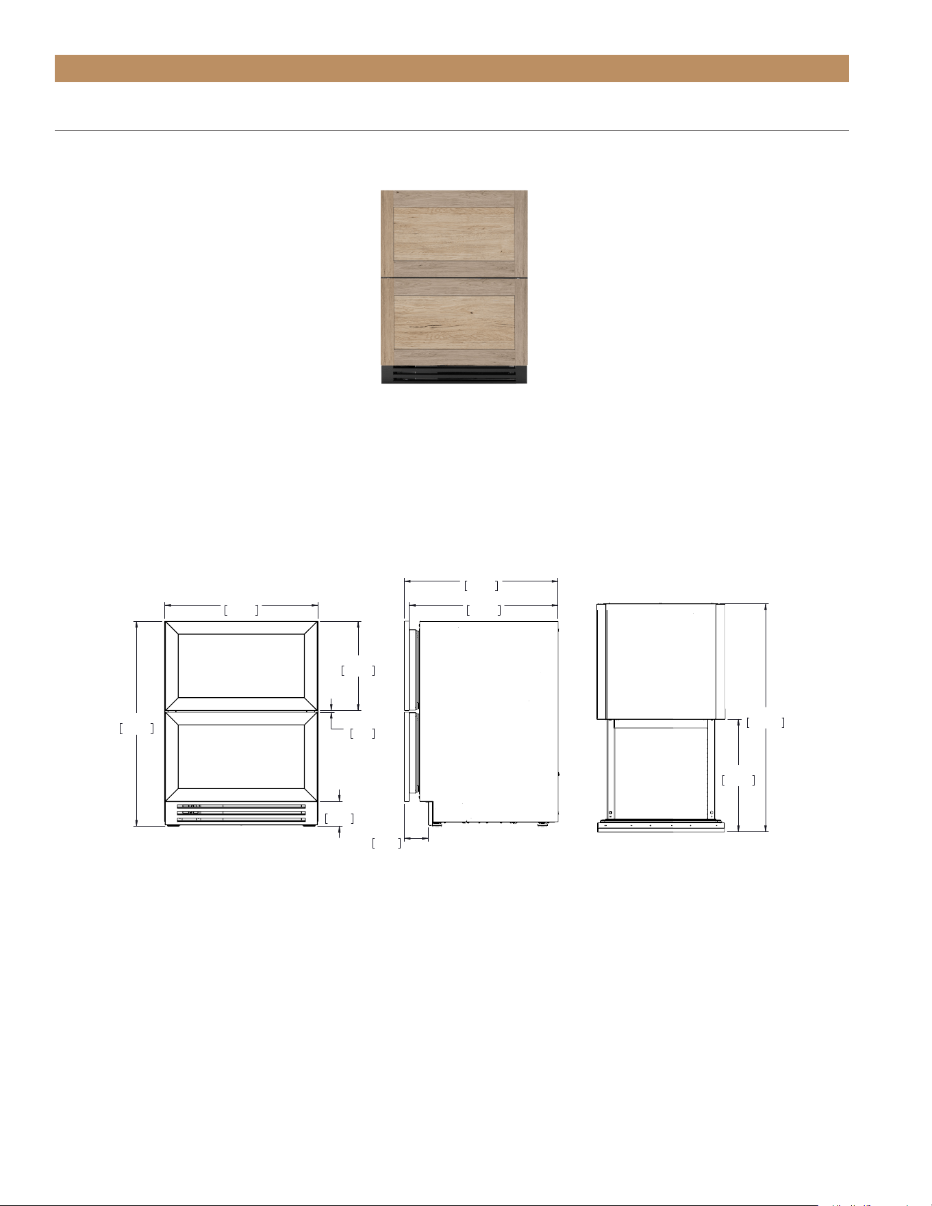
STAINLESS DRAWER UNITS
PLAN VIEW DIMENSIONS
REFRIGERATOR
TURADA-24D-SS-A
23 7/8"
607mm
31 7/8"
810mm
3 7/8"
98mm
23 15/16"
608mm
23 5/32"
588mm
3 3/4"
95mm
25 27/32"
656mm
44 1/2"
1130mm
21"
533mm
22 29/32"
582mm
TURADA-24-D-A~S
09/24/20
Dimensions may vary by ± 1/8" (3.2 mm)
ADA HEIGHT INSTALL GUIDETEC_TM_120 | REV. C | EN FR 07/19/2022 Page 19 of 76
23 7/8"
607mm
31 7/8"
810mm
3 7/8"
99mm
23 5/32"
588mm
3 3/4"
95mm
23 15/16"
608mm
90°
25 7/8"
657mm
47 15/32"
1206mm
TURADA-24-LS/RS-A~O
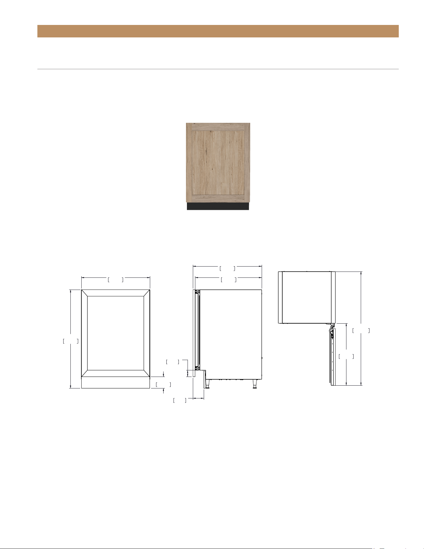
SOLID AND FRAMED GLASS OVERLAY PANEL UNITS
ADA-Compliant door overlay panel shown. For other panel options, please see “Optional Installation Rough
Openings & Plan Views” starting on page 21.
For custom panel specifications, please see “Custom Overlay Panel Specifications” starting on page 25.
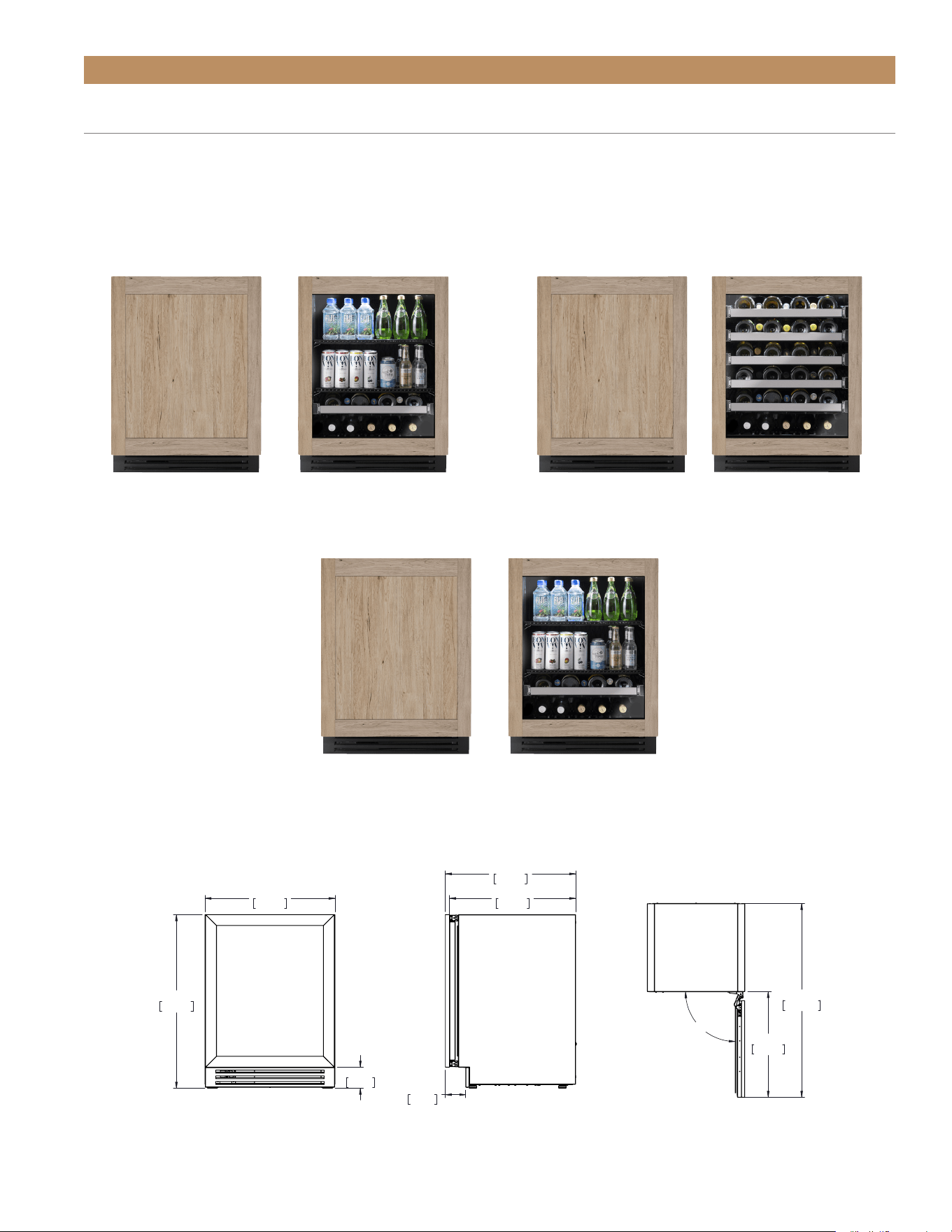
ADA-COMPLIANT INSTALLATION PLAN VIEWS
PLAN VIEW DIMENSIONS*
REFRIGERATORS
BEVERAGE CENTERS
*Depth measurement includes 3/4" thick panel (not provided by TRUE).
Dimensions may vary by ± 1/8" (3.2 mm)
WINE CABINET
TUWADA-24-R/L-RS-A~O TUWADA-24-R/L-RG-A~O
TUBADA-24-R/L-RG-A~O
TURADA-24-R/L-RS-A~O TURADA-24-R/L-RG-A~O
TUBAD A-24-R/L-RS-A~O
TRUE RESIDENTIAL
®
TEC_TM_120 | REV. C | EN FR07/19/2022Page 20 of 76
ADA-COMPLIANT INSTALLATION PLAN VIEWS
OVERLAY PANEL DRAWER UNITS
PLAN VIEW DIMENSIONS*
REFRIGERATOR
TURADA-24-D-A~O
23 7/8"
607mm
31 7/8"
810mm
3 7/8"
98mm
9/32"
7mm
13 7/8"
352mm
23 5/32"
588mm
3 3/4"
95mm
23 15/16"
608mm
21 1/32"
534mm
42 5/8"
1083mm
TURADA-24-D-A~O
*Depth measurement includes 3/4" thick panel (not provided by TRUE).
Dimensions may vary by ± 1/8" (3.2 mm)
ADA HEIGHT INSTALL GUIDETEC_TM_120 | REV. C | EN FR 07/19/2022 Page 21 of 76
Front view
of unit
between
cabinets
OPTIONAL INSTALLATION
OPTIONAL INSTALLATION ROUGH
OPENING & PLAN VIEWS
[34-1/2" (877 MM) OPENING]
Optional installations use combinations of 2-1/2"
(64 mm) leveling legs, 6" (153 mm) grill, and custom
overlay panels to raise (or appear to raise) the overall
height of the unit. For standard installation rough
openings & plan views, see page 16. This section
shows the cabinet specifications for the following
configurations:
A. 2-1/2" leveling legs and 6" grill (stainless steel unit)
B. 2-1/2" leveling legs, 6" grill, and standard door
overlay panel
C. 2-1/2" leveling legs, 6" grill, and tall door overlay
panel
D. Standard leveling legs and tall door overlay panel
OPTIONAL INSTALLATION ROUGH OPENING
Please see the recommended dimensions for a
nonstandard rough opening below. The height includes
2-1/2" (64 mm) leveling legs in the measure. For unit
specifications, please see “Optional Installation Plan
Views” starting on page 21.
ANTI-SWEAT FOAM END PANELS
When installing two or more True units side-by-side,
be sure to leave at least 5/8" (16 mm) gap between the
cabinets, or install foam pads between the cabinets
and on any side without this gap, to prevent moisture
from developing on applications.
If installing ant-sweat foam end panels, True
recommends applying a panel to each of the
units being joined together. To order foam pads,
contact our parts department at 844-849-6226 or
TrueResidentialParts@TrueMfg.com.
HEIGHT
34-1/2"
(877 mm)
DEPTH
24"
(610 mm)
WIDTH
24"
(610 mm)
34-3/8"
(864 mm)
6"
(152 mm)
ROUGH OPENING
23-7/8"
(606 mm)
CUTOUT OPENINGS
To minimize the depth of the cutout opening, the
electrical outlet must be positioned as shown below.
Outlet must be flush with the wall.
2"
(51 mm)
2"
(51 mm)
Rear wall of cut out
8"
(203 mm)
TRUE RESIDENTIAL
®
TEC_TM_120 | REV. C | EN FR07/19/2022Page 22 of 76
OPTIONAL INSTALLATION PLAN VIEWS
A & B. 2-1/2" (64 MM) LEVELING LEGS WITH 6" (153 MM) GRILL AND STANDARD
DOOR (OVERLAY PANEL)
To order a 6” (153 mm) grill (stainless steel or black) or the 2-1/2" (64 mm) leveling legs please contact our parts
department at 844-849-6226 or TrueResidentialParts@TrueMfg.com. For custom panel specifications, please see
“Custom Overlay Panel Specifications” starting on page 25.
TURADA-24-R/L-RS-A~OTURADA-24-R/L-RS-A~S
PLAN VIEW DIMENSIONS*
*Depth measurement includes 3/4" thick panel (not provided by TRUE).
Dimensions may vary by ± 1/8" (3.2 mm)
23 7/8"
607mm
6"
152mm
34 1/4"
870mm
23 5/32"
588mm
3 3/4"
95mm
23 15/16"
608mm
25 7/8"
657mm
47 15/32"
1206mm
ADA HEIGHT INSTALL GUIDETEC_TM_120 | REV. C | EN FR 07/19/2022 Page 23 of 76
OPTIONAL INSTALLATION PLAN VIEWS
C. 2-1/2" (64 MM) LEVELING LEGS WITH 6" (153 MM) GRILL AND TALL DOOR
OVERLAY PANEL (DOOR EXTENDS DOWN)
To order the stainless steel 6" grill or the 2-1/2" (64 mm) leveling legs please contact our parts department at
844-849-6226 or TrueResidentialParts@TrueMfg.com. For custom panel specifications, please see “Custom Overlay
Panel Specifications” starting on page 25.
TURADA-24-R/L-RS-A~O
PLAN VIEW DIMENSIONS*
*Depth measurement includes 3/4" thick panel (not provided by TRUE).
Dimensions may vary by ± 1/8" (3.2 mm)
23 7/8"
607mm
34 1/4"
870mm
4"
102mm
23 5/32"
588mm
3 3/4"
95mm
2 7/32"
57mm
23 15/16"
608mm
25 7/8"
657mm
47 15/32"
1206mm
TRUE RESIDENTIAL
®
TEC_TM_120 | REV. C | EN FR07/19/2022Page 24 of 76
OPTIONAL INSTALLATION PLAN VIEWS
23 7/8"
607mm
34 1/4"
870mm
3 7/8"
98mm
23 5/32"
588mm
3 3/4"
95mm
23 15/16"
608mm
2 11/32"
60mm
25 7/8"
657mm
47 15/32"
1206mm
D. STANDARD LEVELING LEGS WITH TALL DOOR OVERLAY PANEL
(DOOR EXTENDS UP)
For custom panel specifications, please see “Custom Overlay Panel Specifications” starting on page 25.
TUBAD A-24-R/L-RS-A~O
PLAN VIEW DIMENSIONS*
*Depth measurement includes 3/4" thick panel (not provided by TRUE).
Dimensions may vary by ± 1/8" (3.2 mm)
ADA HEIGHT INSTALL GUIDETEC_TM_120 | REV. C | EN FR 07/19/2022 Page 25 of 76
OPTIONAL INSTALLATION
Overlay units can be fitted with custom panels to
match adjacent cabinetry. Please see this section for
recommended panel specifications.
NOTE: PANEL HEIGHT CAN EXCEED THESE
RECOMMENDATIONS BASED ON ROUGH
OPENING SIZE AND CABINET SPECIFICATIONS.
True units assume 3/4" (19mm) thick overlay panels
of the specified width (see spefiications tables) to
be supplied by the end user or others. Thicker/wider
panels increase the potential for panel interference.
See fig. 1.
NOTE: THIS INTERFERENCE CAN BE
MINIMIZED WITH A 90° DOORSTOP. SEE
“90° DOORSTOP INSTALLATION” (PAGE #).
CUSTOM OVERLAY PANEL SPECIFICATIONS
FIG. 1.
Panels 3/4" (19 mm) thick are designed to not interfere with
surrounding units or cabinetry.
115°
3/4" (19 mm)
panel(s)
TRUE RESIDENTIAL
®
TEC_TM_120 | REV. C | EN FR07/19/2022Page 26 of 76
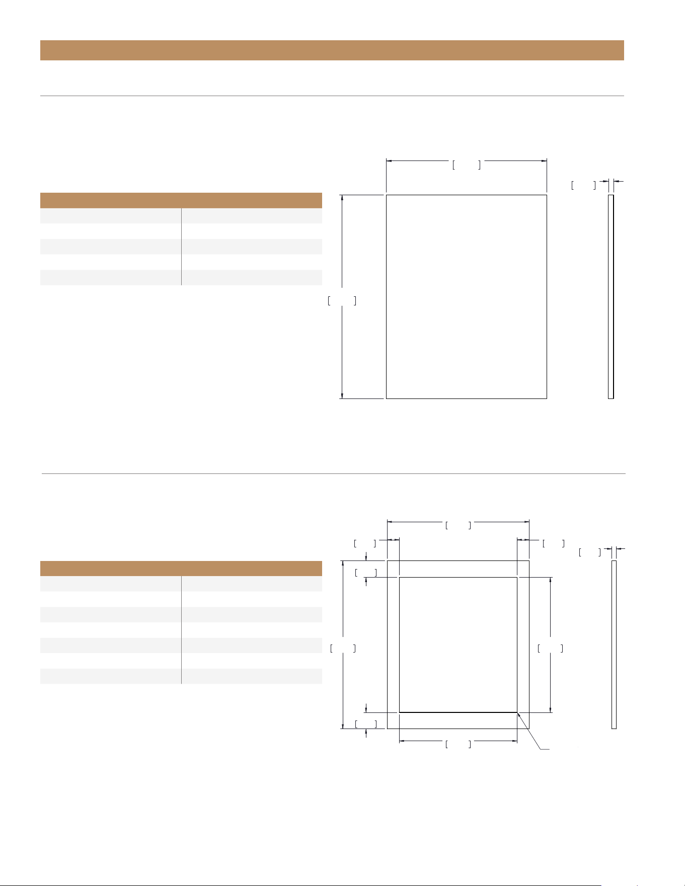
OPTIONAL INSTALLATION
STANDARD SOLID DOOR OVERLAY PANEL – OPTIONAL INSTALLATIONS A & B
For panel installation instructions, please see “Door Overlay Panel Installation” (page 44). For optional lock
installation instructions, please see “Optional Lock Installation” (page 42).
SPECIFICATIONS
Panel Width 23-5/8" (600 mm)
Panel Height 28" (711 mm)
Panel Depth 3/4" (19 mm) max
Panel Weight 10 lbs (4.5 kg) max
Rail Style Dimension 2" (50.8 mm) max
23 5/8"
600mm
28"
711mm
3/4"
19mm
ADA OVERLAY DOOR
23 11/16"
602mm
28"
711mm
22 1/2"
572mm
19 5/8"
498mm
2 3/4"
70mm
2 3/4"
70mm
2 1/32"
52mm
2 1/32"
52mm
GLASS CUT OUT
3/4"
19mm
R
23 11/16"
602mm
28"
711mm
22 1/2"
572mm
19 5/8"
498mm
2 3/4"
70mm
2 3/4"
70mm
2 1/32"
52mm
2 1/32"
52mm
GLASS CUT OUT
3/4"
19mm
R
23 5/8"
600mm
28"
711mm
3/4"
19mm
ADA OVERLAY DOOR
SPECIFICATIONS
Panel Width 23-11/16" (602 mm)
Panel Height 28" (711 mm)
Panel Depth 3/4" (19 mm) max
Panel Weight 10 lbs (4.5 kg) max
Rail Style Dimension 2" (50.8 mm) max
Viewable Area Width 19-5/8" (498 mm)
Viewable Area Height 22-1/2" (572 mm)
STANDARD FRAMED GLASS DOOR OVERLAY PANEL –
OPTIONAL INSTALLATIONS A & B
For panel installation instructions, please see “Door Overlay Panel Installation” (page 44).
ADA HEIGHT INSTALL GUIDETEC_TM_120 | REV. C | EN FR 07/19/2022 Page 27 of 76
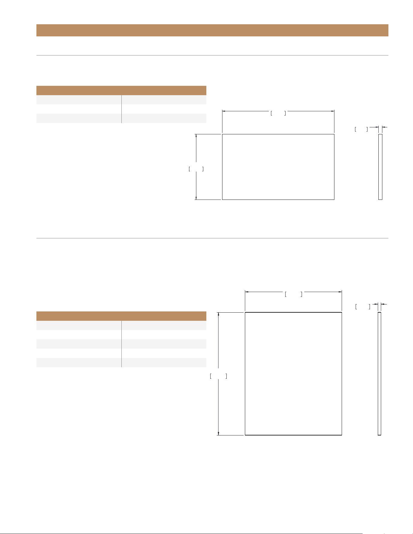
OPTIONAL INSTALLATION
SPECIFICATIONS
Panel Width 23-5/8" (600 mm)
Panel Height 30" (762 mm)
Panel Depth 3/4" (19 mm)
Panel Weight 10 lbs (4.5 kg) max
Rail Style Dimension 2" (50.8 mm) max
TALL DOOR OVERLAY PANEL – OPTIONAL INSTALLATIONS C & D
Overlay units can be fitted with custom panels to match adjacent cabinetry. For example, the tall door overlay
panel can extend the apparent height of the unit or disguise the actual height of a 6" (600 mm) grill. For more
detail, please see “Optional Installations Rough Opening & Plan Views” starting on page 21. Please see below for
panel specifications.
23 5/8"
600mm
28"
711mm
3/4"
19mm
ADA OVERLAY DOOR
23 5/8"
600mm
28"
711mm
3/4"
19mm
ADA OVERLAY DOOR
23 11/16"
602mm
13 27/32"
352mm
3/4"
19mm
R
DRAWER OVERLAY PANEL
For panel installation instructions, please see “Drawer Overlay Panel Installation” (page 46).
SPECIFICATIONS
Panel Width 23-11/16" (602 mm)
Panel Height 13-27/32" (352 mm)
Panel Depth 3/4" (19 mm) max
TOP & BOTTOM DRAWER
PANEL DIMENSIONS
TRUE RESIDENTIAL
®
TEC_TM_120 | REV. C | EN FR07/19/2022Page 28 of 76
OPTIONAL INSTALLATION
6" (153 MM) OVERLAY LOUVER GRILL TEMPLATE –
OPTIONAL INSTALLATIONS A, B, & C
2-1/2" (64 mm) leveling legs create a visible gap between the bottom of the grill and the floor. To conceal this gap
with overlay, please see the custom overlay louver grill template below.
0"
0mm
3/4"
19mm
1 3/4"
44mm
5 15/16"
151mm
0"
0mm
11 7/8"
302mm
23 3/4"
603mm
11 7/8"
302mm
1/2"
13mm
3/4"
19mm
1 15/32"
37mm
3/4"
19mm
2X
.1250
.1250
2X .5000 X 20.2500 THRU
BACK VIEW
6" GRILL TEMPLATE
STANDARD OVERLAY LOUVER GRILL TEMPLATE – OPTIONAL INSTALLATION D
If so desired, you can replace the kickplate with a custom overlay louver grill. Please see the template below.
0"
0mm
3/4"
19mm
1 3/4"
44mm
3 5/8"
92mm
0"
0mm
11 7/8"
302mm
23 3/4"
603mm
11 7/8"
302mm
1/2"
13mm
3/4"
19mm
1 15/32"
37mm
3/4"
19mm
2X
.1250
.1250
2X .5000 X 20.2500 THRU
BACK VIEW
4" GRILL TEMPLATE
ADA HEIGHT INSTALL GUIDETEC_TM_120 | REV. C | EN FR 07/19/2022 Page 29 of 76
OPTIONAL INSTALLATION
• Custom door overlay panels must be at least
23-5/8" (600 mm) x 28" (711 mm) x 3/4" (19 mm)
to cover the panel-ready door front. Your panel
dimensions may vary based on the rough opening
size and / or adjacent cabinetry specifications.
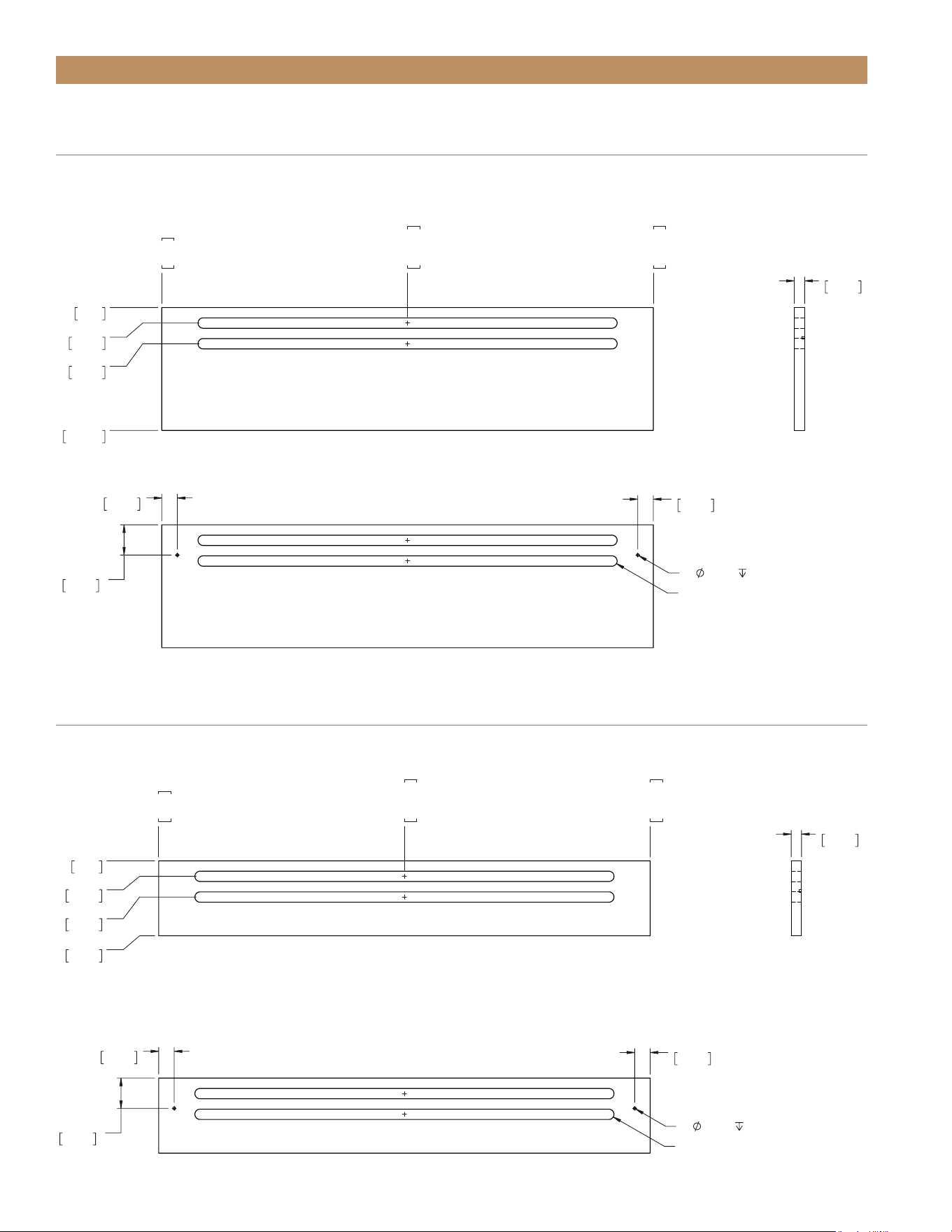
FIG. 1.
Door front pre-drilled hole locations and measurements.
ADDITIONAL DOOR OVERLAY PANEL INFORMATION
• For correct hinge operation, be sure to install door
overlay panels with its hinge side aligned flush with
the door front’s hinge side.
• Doors have pre-drilled holes to assist overlay panel
installation. See fig. 1.
8X
.1560
0"
0mm
9/16"
14mm
3 13/16"
97mm
21 9/16"
548mm
24 13/16"
630mm
25 3/8"
645mm
0"
0mm
29/32"
23mm
5 13/16"
147mm
17 27/32"
453mm
22 3/4"
577mm
23 5/8"
600mm
DOOR FRONT HOLE LOCATIONS
09/24/21
°09
"8/7 52
mm756
"
23/51 74
mm6021
"23/13 2
mm57
"23/5 32
mm885
"61/3 5
mm231
"8/7 32
mm706
"8/7 13
mm018
O~A-SR-42-ADARUT
TRUE RESIDENTIAL
®
TEC_TM_120 | REV. C | EN FR07/19/2022Page 30 of 76
FIG. 2.
Drawer front pre-drilled hole locations and measurements.
8X
.1660
0"
0mm
17/32"
14mm
1 7/8"
48mm
10 5/8"
270mm
11 31/32"
304mm
12 17/32"
318mm
0"
0mm
29/32"
23mm
5 29/32"
150mm
17 23/32"
450mm
22 23/32"
577mm
23 5/8"
600mm
DRAWER FRONT HOLE LOCATIONS
09/24/21
OPTIONAL INSTALLATION
ADDITIONAL DRAWER OVERLAY PANEL INFORMATION
• Custom drawer overlay panels must be at least
23-7/8" (607 mm) x 13-5/8" (346 mm) x 3/4"
(19 mm) to cover the panel-ready door front.
Your panel dimensions may vary based on the
rough opening size and / or adjacent cabinetry
specifications.
• Drawer fronts have pre-drilled holes to assist overlay
panel installation. See fig 2.
23 7/8"
607mm
31 7/8"
810mm
5 3/16"
132mm
23 5/32"
588mm
2 31/32"
75mm
20 1/4"
514mm
41 27/32"
1063mm
TURADA-24-D-A~O
ADA HEIGHT INSTALL GUIDETEC_TM_120 | REV. C | EN FR 07/19/2022 Page 31 of 76
PRIOR TO INSTALLATION
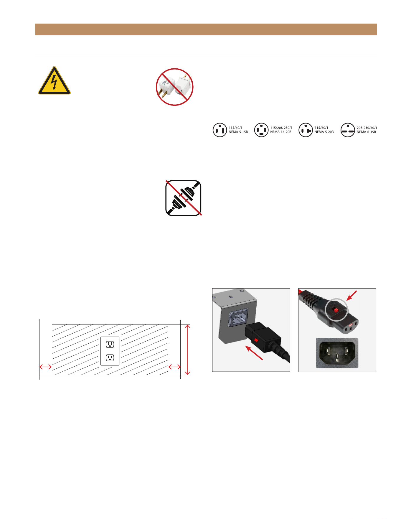
NEVER USE AN ADAPTER
PLUG! An adapter plug
alters the original OEM
plug configuration when
connecting it to a power
source.
TRUE will not warranty any refrigerator/
freezer that has been connected to an
adapter plug.
USE OF EXTENSION CORDS
NEVER USE AN EXTENSION CORD! An
extension cord is determined to be any
component that adds length to the original
OEM power cord when connecting it to a
power source.
TRUE will not warranty any refrigerator/freezer that has
been connected to an extension cord.
CUTOUT OPENINGS
To minimize the depth of the cutout opening, the
electrical outlet must be positioned as shown below.
Outlet must be flush with the wall.
NEMA PLUG CONFIGURATIONS
60 HZ USE ONLY!
TRUE uses these types of NEMA plugs shown. If
you DO NOT have the proper outlet, have a licensed
electrician verify and install the correct power source.
INTERNATIONAL (IEC) PLUGS ONLY
International cabinets may be supplied with a power
cord that will require installation. Install this cord
before connecting the unit to a power source.
NOTE: INTERNATIONAL PLUG
CONFIGURATIONS WILL VARY BY COUNTRY
AND VOLTAGE
INSTALLATION
Fully seat the power cord into the cabinet receptacle
until it locks in position. See fig. 1.
REMOVAL
Depress the red button. See fig. 2.
FIG. 1.
Fully insert the power
cord into the receptacle.
FIG. 2.
Push the red button to
remove the plug.
ELECTRICAL INSTALLATION & SAFETY
2"
(51 mm)
2"
(51 mm)
Rear wall of cut out
8"
(203 mm)

TRUE RESIDENTIAL
®
TEC_TM_120 | REV. C | EN FR07/19/2022Page 32 of 76
PRIOR TO INSTALLATION
HOW TO CONNECT ELECTRICITY
• The power cord from this appliance is equipped
with a grounding plug which minimizes the
possibility of electric shock hazard.
• The wall outlet and circuit should be checked by
a licensed electrician to make sure the outlet is
properly grounded.
• If the outlet is a standard 2-prong outlet, it is your
personal responsibility and obligation to have it
replaced with the properly grounded wall outlet.
• DO NOT, under any circumstances, cut or remove
the ground prong from the power cord. For personal
safety, this appliance must be properly grounded.
• Before your new unit is connected to a power
supply, check the incoming voltage with a voltmeter.
If the recorded voltage is less than the rated voltage
for operation (+/-5%) and amp rating, correct
immediately. Refer to cabinet data plate for this
voltage requirement.
• The refrigerator/freezer should always be plugged
into a dedicated electrical circuit. This provides
the best performance and prevents building wiring
circuits from being overloaded, which could cause
a fire hazard from overheated wires.
• NEVER unplug your refrigerator/freezer by pulling
on the power cord. Always grip plug firmly and pull
straight out from the outlet.
• When moving the refrigerator/freezer, for any
reason, be careful not to roll over or damage
the power cord.
• Repair or replace immediately all power cords that
have become frayed or otherwise damaged.
DO NOT use a power cord that shows cracks or
abrasion damage along its length or at either end.
• If the supply power cord is damaged, it should be
replaced with original equipment manufacturer
(OEM) components. To avoid hazard this should be
done by a licensed service provider.
CABINET WIRING DIAGRAM
The cabinet’s wiring diagram is in the exterior servicing
compartment space of the cabinet. A copy of the
wiring diagram may also be obtained at
www.TrueMfg.com/support/serial-number-lookup
ELECTRICAL INSTALLATION & SAFETY (CONT.)

ADA HEIGHT INSTALL GUIDETEC_TM_120 | REV. C | EN FR 07/19/2022 Page 33 of 76
INSTALLATION
UNCRATING
ANTI-TIP BRACKET INSTALLATION
LEVELING LEG INSTALLATION
LEVELING
KICKPLATE INSTALLATION
PRESERVE THE MOMENT
®
TRUE RESIDENTIAL
®
TEC_TM_120 | REV. C | EN FR07/19/2022Page 34 of 76
UNCRATING
REQUIRED TOOLS
Required tools include (but may not be limited to) the
following:
• Cutting Tool
• Hammer
• Crowbar
• Phillips Screwdriver
• Floor Protector
PROCEDURE
The following procedure is recommended for uncrating
the unit:
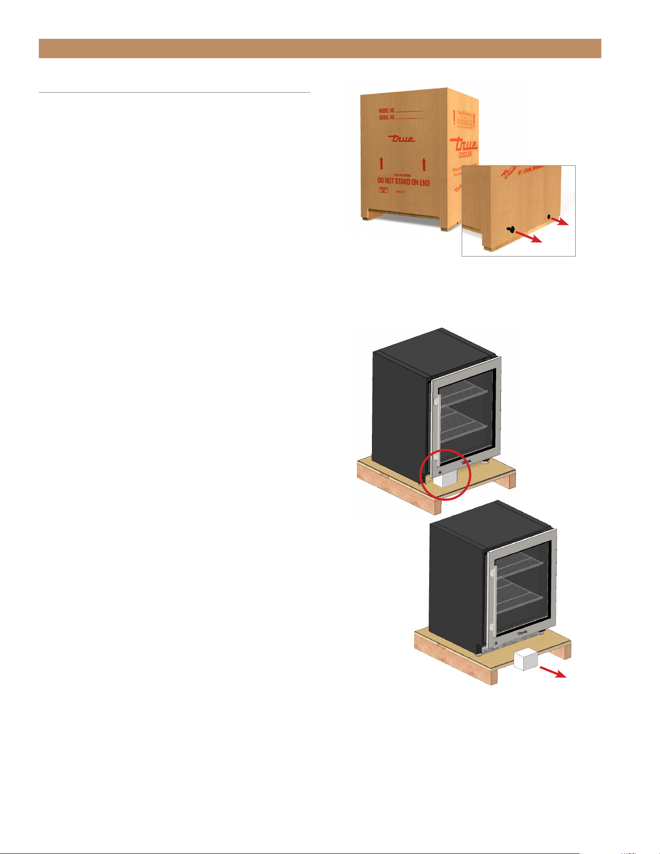
1. Remove the outer packaging (cardboard and clear
plastic). See fig. 1. Inspect for concealed damage.
Again, immediately file a claim with the freight carrier
if there is damage.
2. Cut the plastic band and remove the Styrofoam
block. See fig. 2.
NOTE: MOVE THE UNIT AS CLOSE AS
POSSIBLE TO ITS FINAL LOCATION BEFORE
REMOVING THE SKID.
3. Position the floor protector next to the skid.
4. Carefully lift the unit off the skid and place the unit
on the floor protector.
NOTE: DO NOT LIFT THE CABINET BY THE
COUNTERTOPS, DOORS, DRAWERS, OR
GRILLS.
5. Remove the interior packaging.
NOTE: KEYS FOR THE UNIT ARE INSIDE
THIS PACKET.
6. If applicable, remove the wire shelving, shelf clips,
and/or floor wine cradle packed on top of the unit.
For shelving installation instructions, see page 24.
INSTALLATION
FIG. 1.
Pull the cardboard from the pallet.
FIG. 2.
Remove the foam block after moving the unit
as close as possible to the final installation location.
ADA HEIGHT INSTALL GUIDETEC_TM_120 | REV. C | EN FR 07/19/2022 Page 35 of 76
INSTALLATION
ANTI-TIP BRACKET INSTALLATION
KIT CONTENTS
• 2 – Anti-Tip Brackets
• 4 – 3/16" x 2-1/4" Concrete Screws
• 4 – 12 x 2" Phillips Wood Screws
REQUIRED TOOLS
Required tools include (but may not be limited to) the
following:
• Floor Protector
• Tape Measure
• Marking Utensil
• 1/8" Drill Bit*
• Phillips Bit Driver or 1/4" Hex-Head Driver
• Drill
*Drill bit type will vary by flooring material.
CAUTION – ALL FREESTANDING DRAWER
OR STACKED UNITS MUST HAVE ANTI-TIP
BRACKETS INSTALLED.
Install the anti-tip brackets before moving the unit into
its final operating position. Contact a qualified flooring
installer for the best procedure of drilling mounting
holes through your flooring material.
PROCEDURE
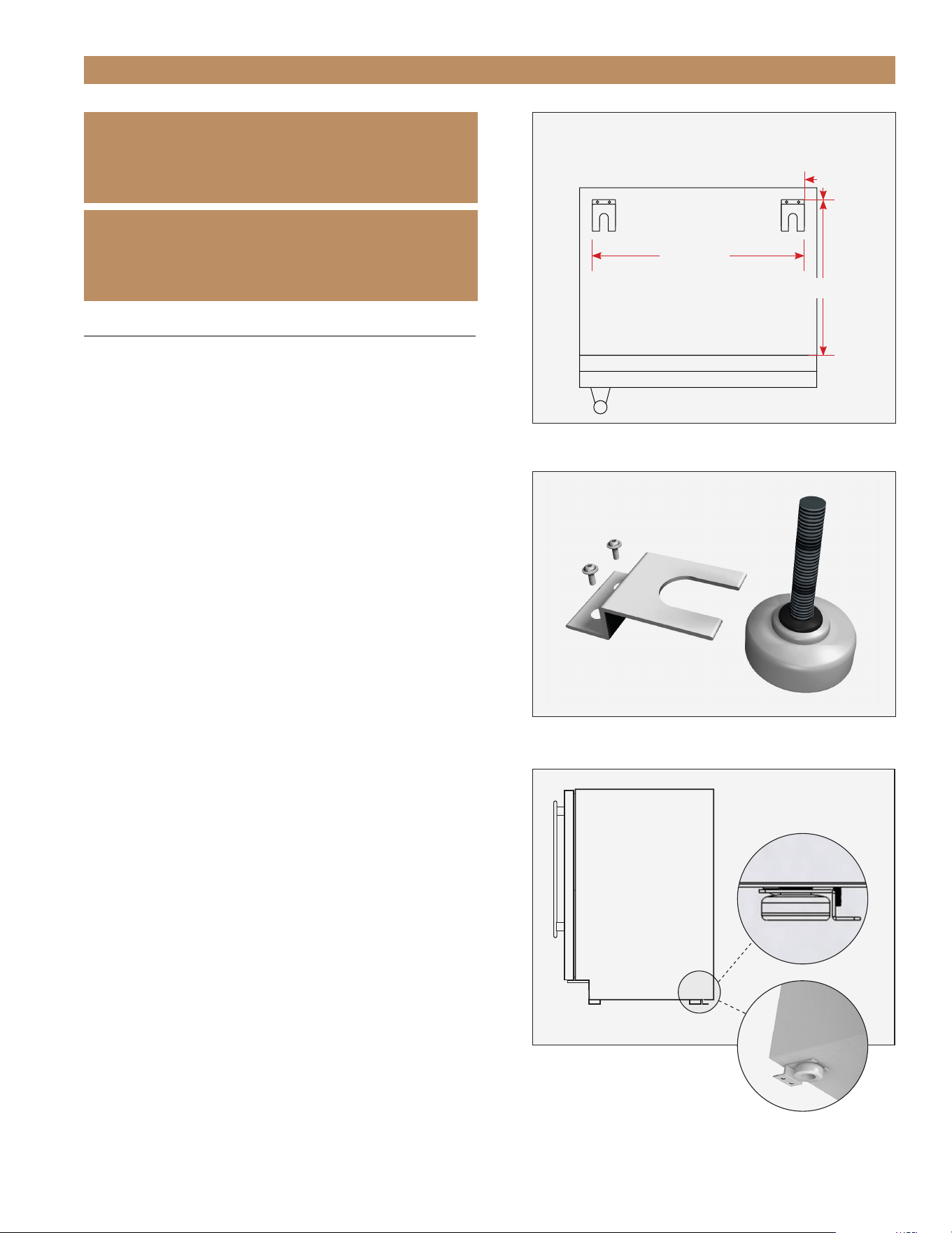
1. Place the unit on the floor protector.
2. Determine the final installation location of the unit.
Measure 27/32" (22 mm) inset from the sides
and either 27/32" from the back or 18-1/2"
(470 mm) from the front (measure does not
include the kickplate). See fig. 1.
IMPORTANT!
ALL FREE STANDING DRAWER OR STACKED
UNITS MUST HAVE ANTI-TIP BRACKETS INSTALLED.
IMPORTANTE!
TOUS LES TIROIRS AUTOPORTANTS OU LES UNITÉS
EMPILÉES DOIVENT AVOIR DES SUPPORTS ANTI-
BASCULEMENT INSTALLÉS.
Anti-Tip Bracket (top view)
Back
Front
18-1/2"
22-3/16"
27/32"
FIG. 1.
Top plan view of anti-tip bracket positioning.
FIG. 2.
Securely fasten the anti-tip brackets to the floor.
FIG. 3.
Be sure the rear leveling legs slide into the brackets.
TRUE RESIDENTIAL
®
TEC_TM_120 | REV. C | EN FR07/19/2022Page 36 of 76
INSTALLATION
3. Position the anti-tip brackets and mark the
mounting hole locations.
4. With a 1/8" drill bit, drill pilot holes at the marked
locations.
NOTE: BE SURE TO USE A DRILL BIT
APPROPRIATE FOR YOUR FLOORING
MATERIAL.
5. With the appropriate provided hardware, install the
anti-tip brackets. See fig. 2.
NOTE: THE CONCRETE SCREWS ARE BLUE.
6. Carefully position the unit in its final installation
location. Be sure the rear leveling legs slide into
the anti-tip brackets. See fig. 3.
NOTE: DO NOT LIFT THE CABINET BY THE
COUNTERTOPS, DOORS, DRAWERS, OR
GRILLS.
LEVELING LEGS
Standard leveling legs are provided to assist with
leveling the cabinet.
PROCEDURE
With access to the bottom of the cabinet, turn the
leveling legs to adjust the level as needed.
See figs. 1 and 2.
2-1/2" (64mm) LEVELING LEGS
2-1/2" (64 mm) leveling legs raise the minimum height
of the unit to 33-3/4" (857.25 mm). The leveling
legs are adjustable up to 1" (25.4 mm), raising the
maximum height of the unit to 34-3/4" (882.7 mm).
If so desired, you can order a taller grill to hide
the gap caused by the 2-1/2" leveling legs. Please
contact our parts department at 844-849-6226 or
TrueResidentialParts@TrueMfg.com.
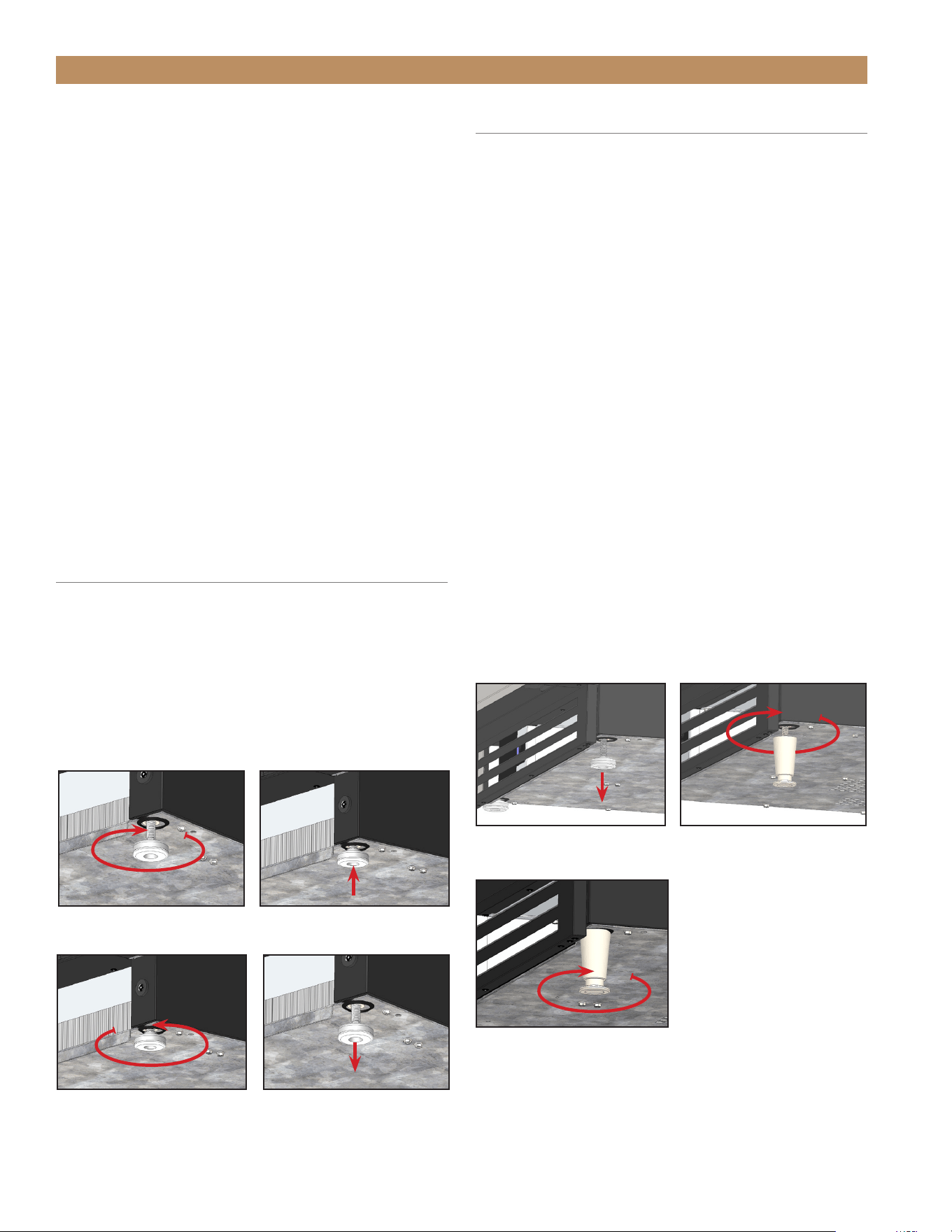
PROCEDURE
1. Access the bottom of the cabinet.
2. Remove the existing standard leveling legs.
See fig. 3.
3. Thread the new leveling legs into the bottom of
the cabinet. See fig. 4.
4. Verify the level of the cabinet. If the cabinet is
not level, gently lift and support the low end of
the cabinet. Then, adjust the bottom stem of the
leveling leg to level and support the cabinet.
See fig. 5.
FIG. 1.
Turn the leveling legs clockwise to lower the unit.
FIG. 2.
Turn the leveling legs counterclockwise to raise the unit.
FIG. 5.
Turn the bottom stem to
level the cabinet.
FIG. 3.
Remove the existing
leveling legs.
FIG. 4.
Screw in the leveling legs.
ADA HEIGHT INSTALL GUIDETEC_TM_120 | REV. C | EN FR 07/19/2022 Page 37 of 76
INSTALLATION
LEVELING
Proper leveling of your TRUE unit is critical to
operating success. Leveling impacts effective
condensate removal and door operation.
With the cabinet in the final installation location, level
the unit front-to-back and side-to-side.
PROCEDURE
1. Position the level on the inside floor of the unit
near the doors (the level should be parallel to
cabinet front). Level the cabinet.
2. Position the level at the inside rear of the cabinet
(again, the level should be placed parallel to
cabinet back). Level the cabinet.
3. Perform procedures similar to steps 1 and 2 by
placing the level on the inside floor (left and right
side, parallel to the depth of the cooler). Level the
cabinet.
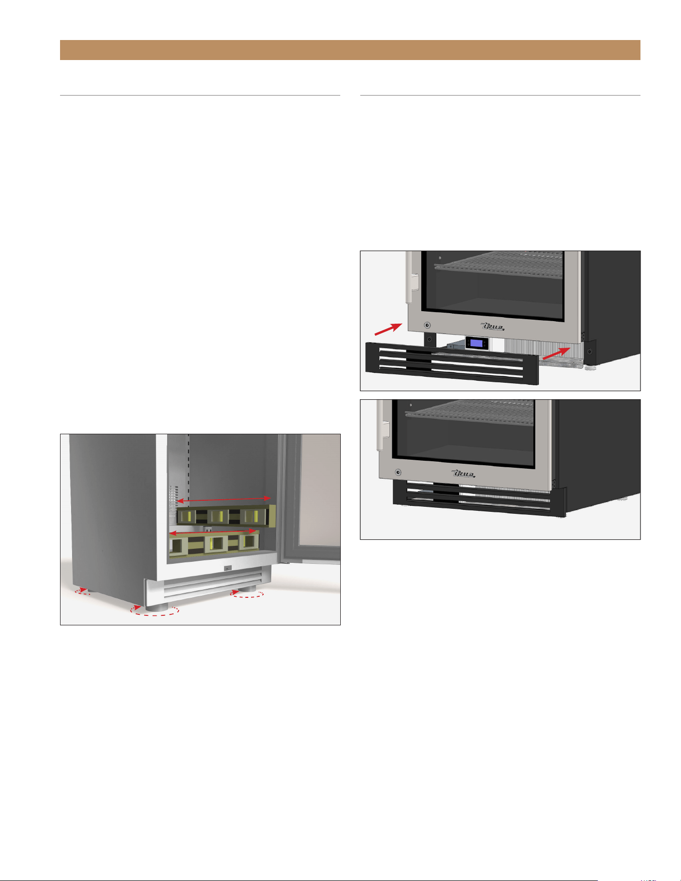
KICKPLATE INSTALLATION
PROCEDURE
1. Locate the kickplate secured to the back of the
unit.
2. Position the kick plate below the door. See fig. 1.
3. Verify the kickplate correctly aligned. Adjust as
needed.
FIG. 1.
Attach the kickplate to the magnets below the door.

TRUE RESIDENTIAL
®
TEC_TM_120 | REV. C | EN FR07/19/2022Page 38 of 76
NOTES

ADA HEIGHT INSTALL GUIDETEC_TM_120 | REV. C | EN FR 07/19/2022 Page 39 of 76
CABINET SETUP
SHELF INSTALLATION
LOGO INSTALLATION
OPTIONAL LOCK INSTALLATION
DOOR OVERLAY INSTALLATION
DRAWER OVERLAY INSTALLATION
90° DOORSTOP INSTALLATION
PRESERVE THE MOMENT
®
TRUE RESIDENTIAL
®
TEC_TM_120 | REV. C | EN FR07/19/2022Page 40 of 76
CABINET SETUP
Shelf
Clip
Shelf
Shelf
Pillaster
(I-beam)
Shelf
Standards
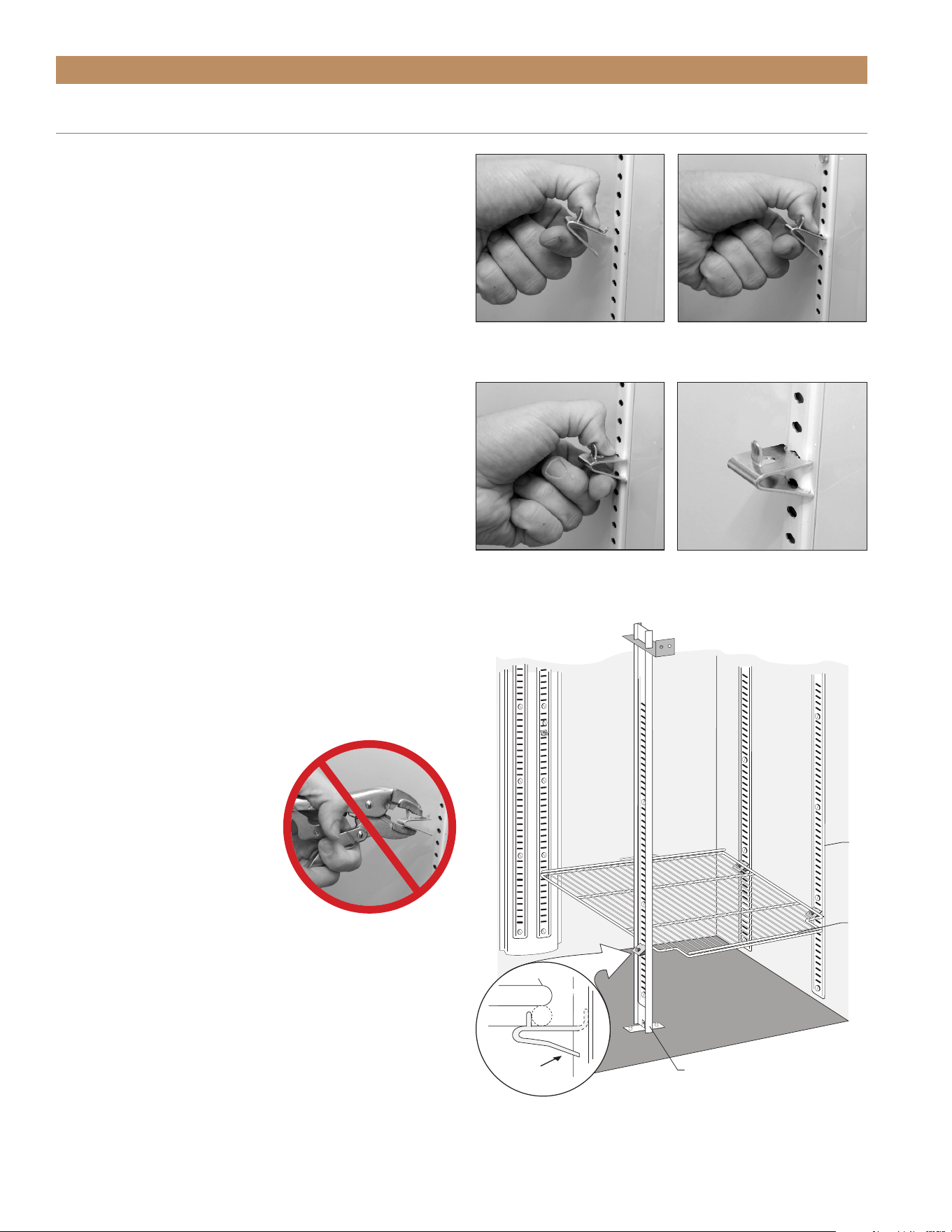
PROCEDURE
1. Hook the shelf clips into the shelf standards.
See fig. 1.
2. Push up on the bottom of the clip. See fig. 2.
NOTE: YOU MAY NEED TO SQUEEZE OR
TWIST THE BOTTOM OF THE SHELF CLIP
FOR PROPER INSTALLATION. POSITION ALL
FOUR SHELF CLIPS EQUAL IN DISTANCE
FROM THE FLOOR FOR FLAT SHELVES.
3. Ensure the shelf clip is not loose or able to wiggle
out of the shelf standard. See figs. 3 and 4.
4. Place the shelves on the shelf clips with the cross
support bars facing down.
NOTE: BE SURE ALL SHELF CORNERS ARE
PROPERLY SEATED.
INSTALLATION TIPS
• Install all the shelf clips before installing any
shelves.
• Start at the bottom shelf and work your way up.
• Always lay the back of each shelf down on the
rear clips before the front.
WARNING – DO NOT USE
PLIERS OR ANY CRIMPING
TOOLS WHEN INSTALLING
SHELF CLIPS. ALTERING
SHELF CLIPS IN ANY WAY
CAN LEAD TO SHELVING
INSTABILITY.
SHELF INSTALLATION
FIG. 1.
Installing top tab of
shelf clip.
FIG. 2.
The bottom tab of the
shelf clip will fit tightly
FIG. 3.
You may need to squeeze
or twist the bottom of the shelf
clip to install.
FIG. 4.
Installed shelf clip.
ADA HEIGHT INSTALL GUIDETEC_TM_120 | REV. C | EN FR 07/19/2022 Page 41 of 76
LOGO INSTALLATION
CABINET SETUP
For door units, the TRUE logo ships separately to keep
the door field reversible. For instructions on reversing
the door, see “Reversing Door” (page 65).
When the door is oriented as desired, install the logo
as described below.
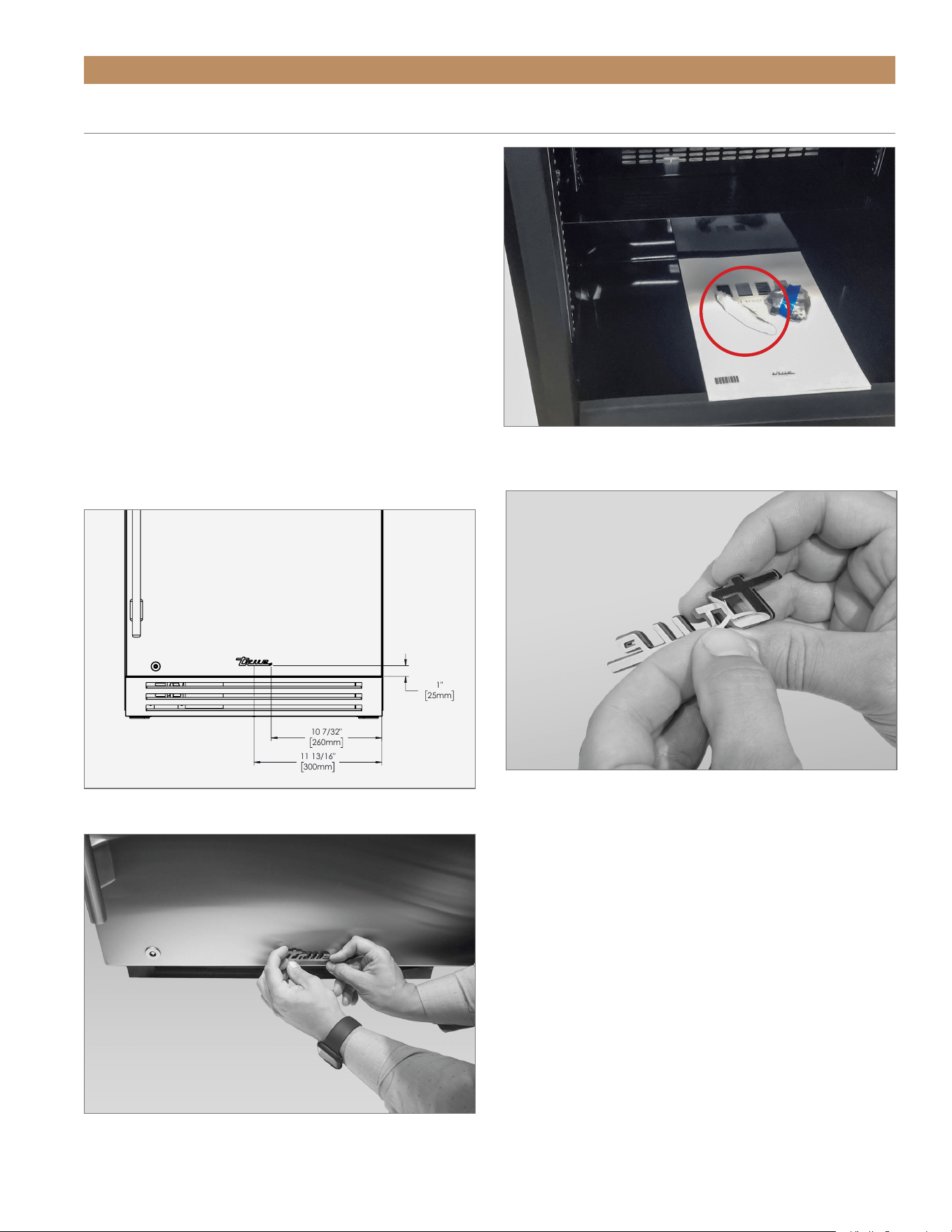
PROCEDURE
1. Locate the logo in the interior packaging. See fig.
1.
2. Determine the desired location for the logo. True
typically puts the logo at the midpoint (see fig. 2).
3. Remove the sticker backing and apply the logo to
the door. See figs. 3 and 4.
FIG. 4.
Carefully apply the logo centered at the bottom of the door.
Adhesive bonds upon contact.
FIG. 3.
Peel the backing from the adhesive.
FIG. 2.
True logo installation location.
1"
25mm
11 13/16"
300mm
10 7/32"
260mm
TURADA-24-RS-A~S
FIG. 1
. Logo shipping location.
TRUE RESIDENTIAL
®
TEC_TM_120 | REV. C | EN FR07/19/2022Page 42 of 76
CABINET SETUP
OPTIONAL LOCK INSTALLATION
Follow the instructions below to install a lock assembly
in your overlay panel. If converting to overlay from
stainless, reuse the existing lock. Otherwise, to order a
lock assembly, please contact our parts department at
844-849-6226 or TrueResidentialParts@TrueMfg.com.
REQUIRED TOOLS
Required tools include (but may not be limited to)
the following:
• 1/8" Allen key wrench
• Phillips Screwdriver or Bit Driver
• Adjustable Lock Nut Wrench
• 3/4" hole saw with shank or similar
• 1-1/4" drill bit for countersunk hole
• Tools required for creating 1/4" (6.35 mm) notch
• Drill
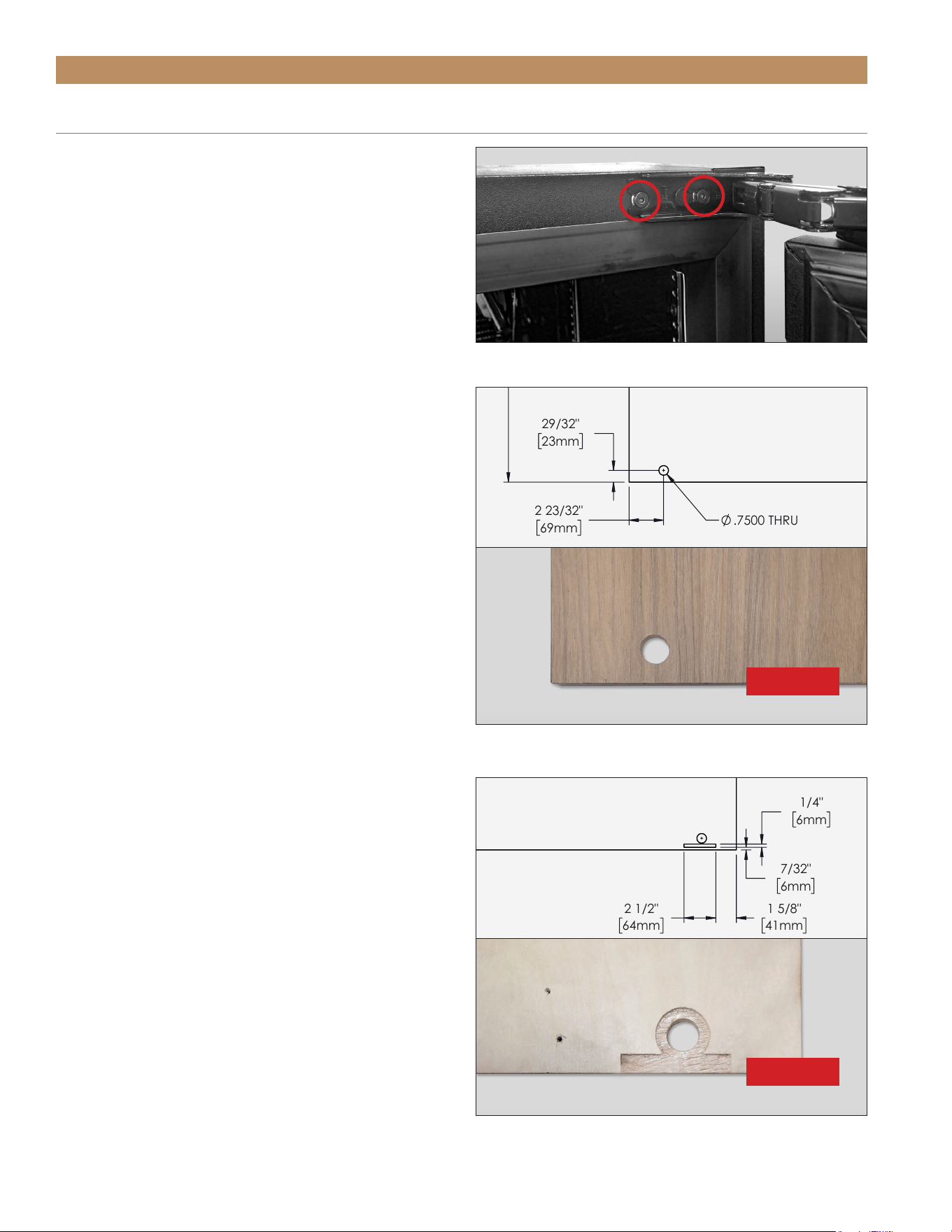
PROCEDURE
NOTE: FIGURES SHOW RIGHT-HINGED DOOR.
1. With a 1/8" hex head Allen wrench, loosen the
cabinet hinge bolts. See fig. 1.
NOTE: DO NOT REMOVE THE HINGE FROM
THE DOOR ASSEMBLY.
2. Carefully create the lock bracket notch and the
countersunk lock assembly hole in the overlay
panel. See figs. 2 and 3.
NOTE: TAKE CARE TO NOT DAMAGE THE
PANEL’S FINISH.
FIG. 1
. The articulating hinge uses keyhole slots.
FIG. 2.
Panel front. Lock assembly hole position. Rotate 180° for left-
hinged units.
23 5/8"
600mm
28"
711mm
2 23/32"
69mm
29/32"
23mm
.7500 THRU
3/4"
19mm
1/4"
6mm
NOTCH DEPTH
1 5/8"
41mm
1/4"
6mm
2 1/2"
64mm
7/32"
6mm
BACK VIEW
ADA OVERLAY DOOR FOR 6" GRILL
WITH LOCK
FIG. 3.
Panel back. Countersunk lock assembly hole and lock bracket
notch positions. Rotate 180° for left-hinged units.
23 5/8"
600mm
28"
711mm
2 23/32"
69mm
29/32"
23mm
.7500 THRU
3/4"
19mm
1/4"
6mm
NOTCH DEPTH
1 5/8"
41mm
1/4"
6mm
2 1/2"
64mm
7/32"
6mm
BACK VIEW
ADA OVERLAY DOOR FOR 6" GRILL
WITH LOCK
FRONT
BACK
ADA HEIGHT INSTALL GUIDETEC_TM_120 | REV. C | EN FR 07/19/2022 Page 43 of 76
CABINET SETUP
OPTIONAL LOCK INSTALLATION (CONT.)
FI G. 7.
Completed installation.
FIG. 8.
Be sure the door closes with the gasket flush against the unit.
FIG. 6.
Be sure the lock is correctly aligned with the lock bracket.
FIG. 5.
Install the door panel.
FIG. 4.
Verify the lock cam turns towards the closest edge of the panel.
3. Install the lock assembly in the door panel.
See fig. 4.
NOTE: BE SURE THE LOCK CAM TURNS
TOWARDS THE LOCK BRACKET NOTCH.
4. Install the overlay panel. See “Door Overlay Panel
Installation” (page 44). See fig. 5.
5. Install the door assembly. See figs. 6 and 7.
6. Verify the door alignment and that the gasket seals
without gaps. See fig. 8. Adjust as needed.

TRUE RESIDENTIAL
®
TEC_TM_120 | REV. C | EN FR07/19/2022Page 44 of 76
CABINET SETUP
Follow the instructions below to install door overlay
panels. Door panel height and positioning varies by
application; for more details, please see “Standard
Installation Plan Views” (page 16) or “Optional
Installation Plan Views” (page 21). For custom panel
specifications, please see “Custom Overlay Panel
Specifications” starting on page 25.
NOTE: DO NOT INSTALL A SOLID PANEL ON
A GLASS DOOR. THIS MAY CAUSE MOISTURE
TO FORM BEHIND THE PANEL, RESULTING
IN DAMAGE. BE SURE TO INSTALL A LOCK
BEFORE INSTALLING THE DOOR PANEL.
REQUIRED TOOLS
Required tools include (but may not be limited to)
the following:
• Surface protection*
• 2+ Clamps ≥ 2" (51 mm)
• 1/8" Hex Head Allen Wrench
• Phillips Bit Driver
• 1/8" Dill Bit
• (Qty 6) #6 x 1/2" Screws**
• Drill
*Cardboard, moving blanket, foam padding, etc.
**Screw type varies by panel material.
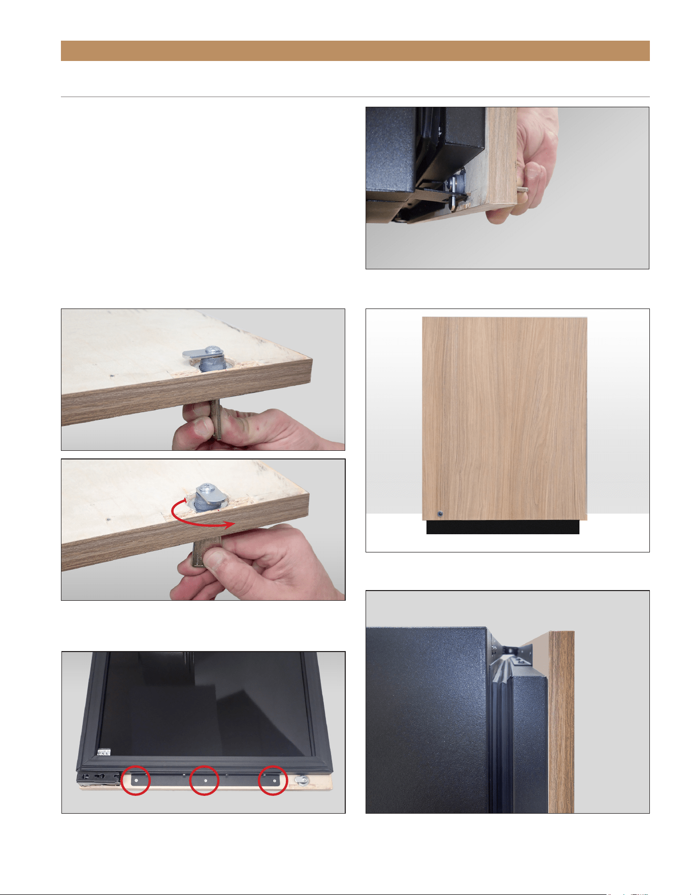
PROCEDURE
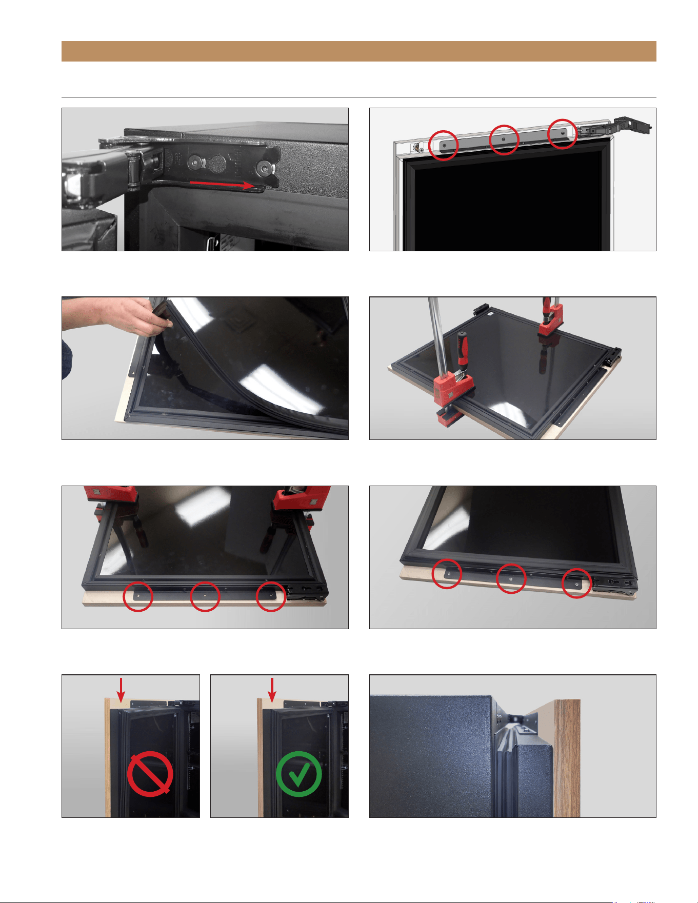
NOTE: FIGURES SHOW A LEFT-HINGED DOOR.
1. Carefully lay the door overlay panel on a protected
surface.
2. With a 1/8" hex head Allen wrench, loosen the
cabinet hinge bolts. Then, remove the door.
See fig. 1.
NOTE: DO NOT REMOVE THE HINGE FROM
THE DOOR ASSEMBLY.
NOTE: IF CONVERTING FROM STAINLESS
STEEL DOOR SKIN TO AN OVERLAY
PANEL, REMOVE THE DOOR SKIN BEFORE
POSITIONING THE DOOR FRONT ON THE
PANEL. DO NOT REMOVE THE DOOR SKIN
BRACKET FROM THE DOOR FRONT.
SEE FIG. 2.
3. Remove the gasket. See fig. 3.
4. Place the door front face down on the overlay
panel. Align the door front and panel edges. See
fig. 4.
NOTE: THE PANEL’S VERTICAL
POSITIONING AND LENGTH VARY
BY INSTALLATION. SEE “OPTIONAL
INSTALLATIONS” (PAGE #).
5. Clamp the door and panel. See fig. 4.
NOTE: IF THE CLAMP JAWS ARE NOT
PADDED, INSERT PADDING BETWEEN THE
CLAMP AND THE OVERLAY TO PROTECT
THE PANEL’S FINISH.
6. If desired, install a handle before proceeding to the
next step. For best installation. Fasten the handle
with recessed screws.
7. With a 1/8" drill bit, carefully drill pilot holes into
the door front. See fig. 5.
NOTE: TAKE CARE TO NOT DRILL THROUGH
THE FRONT OF THE PANEL.
8. Fasten the overlay panel to the door front. Then,
remove the clamps. See fig. 6.
9. Install the door gasket. Verify the gasket is fully
seated in the gasket channel. See fig. 7.
10. Install the door assembly. Verify the door closes
correctly and the gasket seals without gaps (see
fig. 8). Adjust the door as needed; see “Door
Adjustment” (page 66).
DOOR OVERLAY PANEL INSTALLATION
ADA HEIGHT INSTALL GUIDETEC_TM_120 | REV. C | EN FR 07/19/2022 Page 45 of 76
CABINET SETUP
DOOR OVERLAY PANEL INSTALLATION (CONT.)
FIG. 3.
Pull the gasket from the door.
FIG. 4.
Be sure the edges are aligned before clamping the door
assembly.
FIG. 8.
Be sure the door closes with the gasket flush against the unit.
FIG. 1.
The articulating hinge uses keyhole slots.
FIG. 2.
STAINLESS STEEL MODELS ONLY: Remove the indicated door
skin bracket screws.
FIG. 5.
Carefully drill pilot holes in the panel.
FIG. 6.
Carefully fasten the panel to the door front.
FI G. 7.
Be sure the gasket is fully seated in the gasket channel.
TRUE RESIDENTIAL
®
TEC_TM_120 | REV. C | EN FR07/19/2022Page 46 of 76
CABINET SETUP
Follow the instructions below to install drawer overlay
panels. For custom panel specifications, please see
“Custom Overlay Panel Specifications” starting on
page 25.
REQUIRED TOOLS
Required tools include (but may not be limited to)
the following:
• Surface protection*
• Phillips bit driver
• 2+ Clamps >/= 2" (51 mm)
• 1/8" Drill Bit
• (Qty 8) #6 x >1/2" Screws**
• (Qty 3) #6 x 1/2" Screws**
• Drill
*Cardboard, moving blanket, foam padding, etc.
** Screw type varies by panel material. Screws going through
the drawer front (rather than the drawer skin bracket) must
be 1/2” (13 mm) + Overlay Panel Thickness long.
PROCEDURE
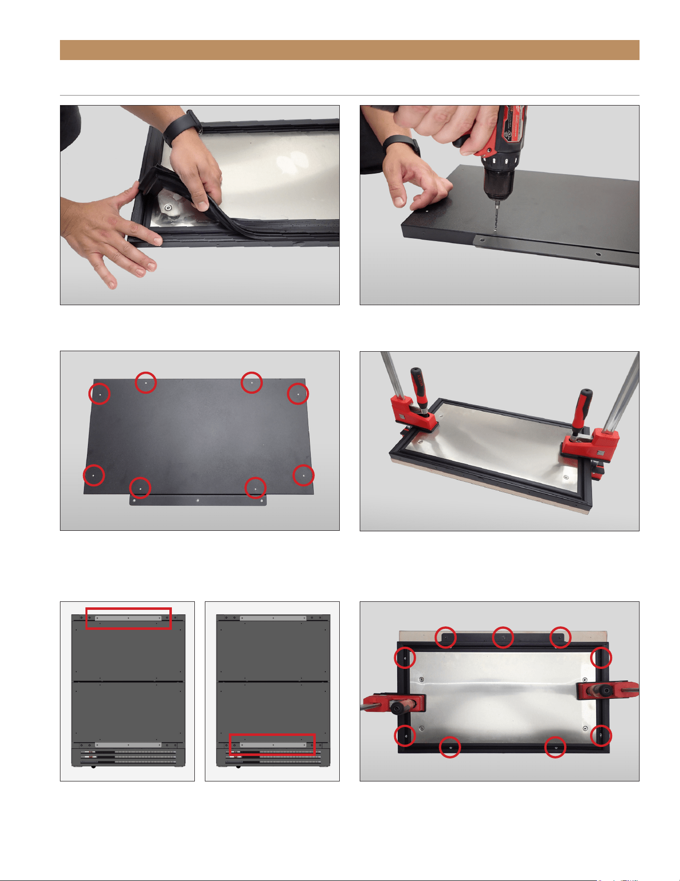
1. Carefully lay the drawer overlay panel on a
protected surface.
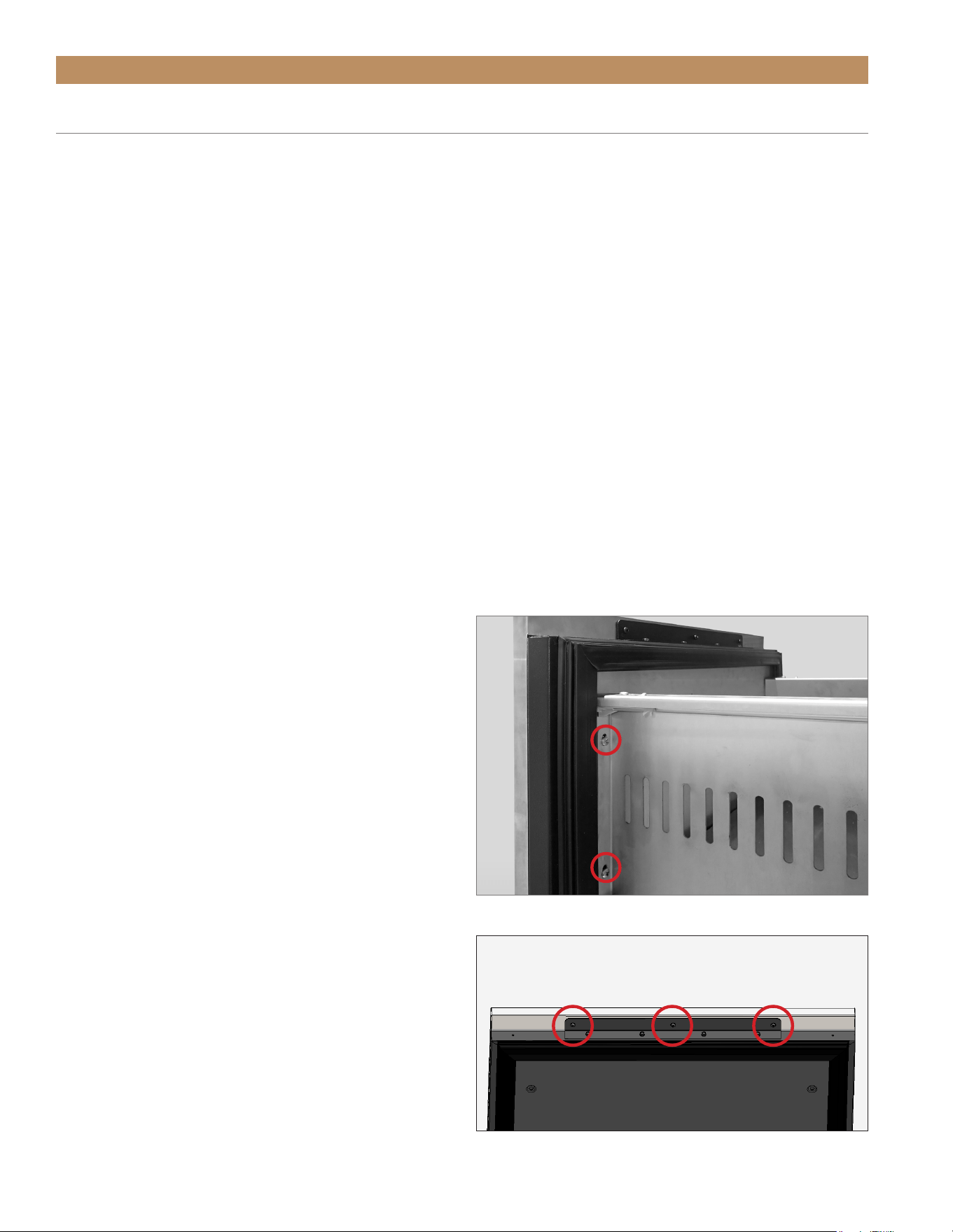
2. With a Phillips bit driver, remove the drawer front
assembly. See fig. 1.
3. If present, remove the drawer skin from the drawer
front. See fig. 2.
NOTE: DO NOT REMOVE THE DRAWER
BRACKETS FROM THE DRAWER FRONT.
4. Remove the drawer gasket. See fig. 3.
5. With a 1/8" drill bit, carefully drill pilot holes in the
drawer front. See figs. 4a and 4b.
6. If so desired, attach a drawer handle to the overlay
panel.
7. Place the drawer front face down on the overlay
panel. Align the drawer front and panel edges.
See fig. 5.
NOTE: BE SURE THE OVERLAY PANEL IS
CORRECTLY ORIENTED BEFORE INSTALLING
ON THE DRAWER FRONT. SEE FIG. 6.
8. Clamp the drawer front and panel together.
See fig. 5.
NOTE: IF THE CLAMP JAWS ARE NOT
PADDED, INSERT PADDING BETWEEN THE
CLAMP AND THE OVERLAY TO PROTECT
THE PANEL’S FINISH.
9. Fasten the overlay panel to the drawer front. Then,
remove the clamps. See fig. 7.
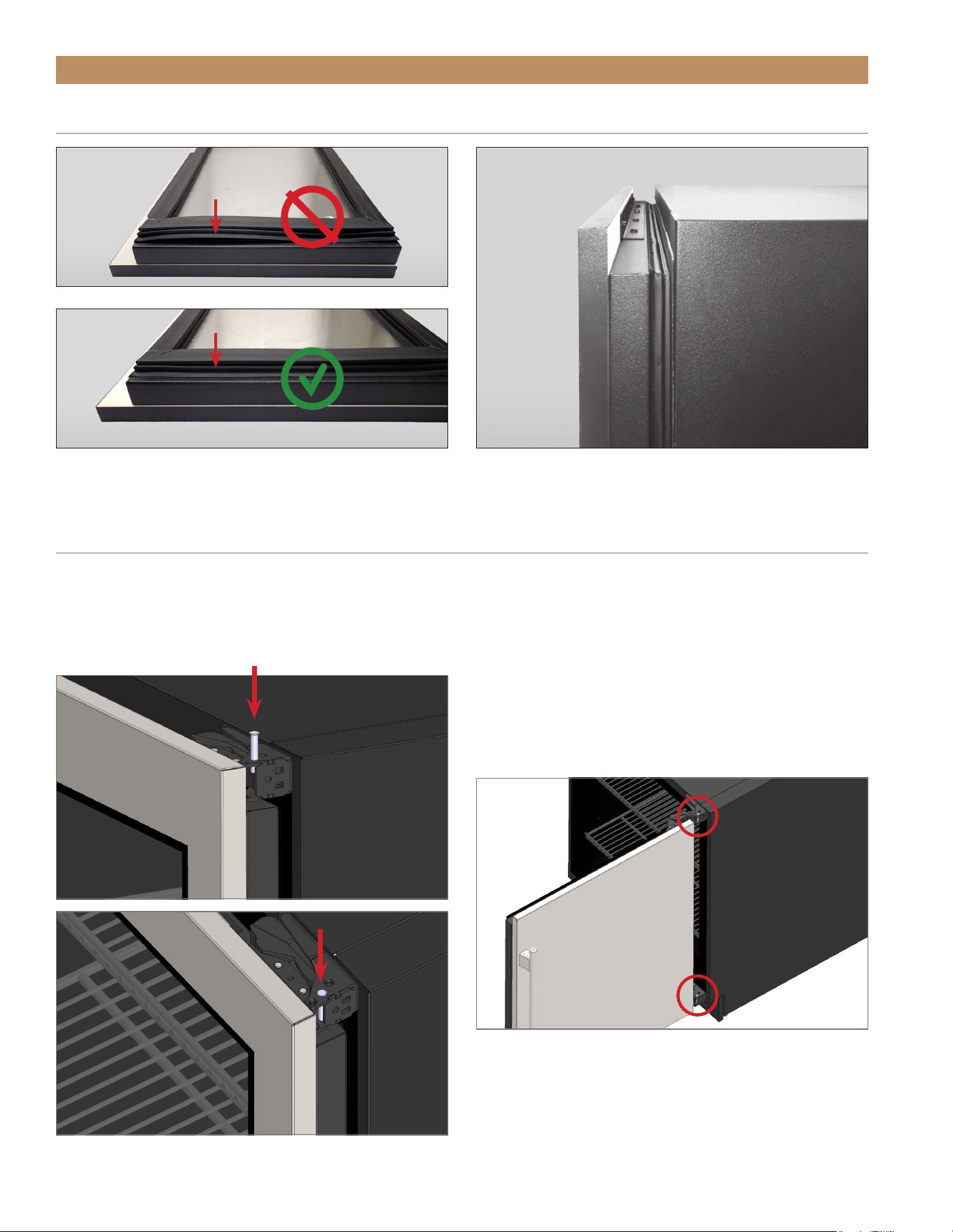
10. Install the drawer gasket. Verify the gasket is fully
seated in the gasket channel. See fig. 8.
11. Install the drawer assembly.
12. Verify the drawer closes correctly and the gasket
seals without gaps (see fig. 9). Adjust the drawer
as needed; see “Drawer Adjustment” (page 66).
DRAWER OVERLAY PANEL INSTALLATION
FIG. 1.
Drawer front assembly screw locations. Other side not shown.
FIG. 2.
Remove the indicated drawer skin bracket screws.
ADA HEIGHT INSTALL GUIDETEC_TM_120 | REV. C | EN FR 07/19/2022 Page 47 of 76
CABINET SETUP
DRAWER OVERLAY PANEL INSTALLATION (CONT.)
FIG. 3.
Pull the gasket from the drawer.
FIG. 5.
Be sure the edges are aligned before clamping the drawer front
assembly.
FIG. 4a.
Drill pilot holes through the drawer front assembly.
FIG. 4b.
Pilot hole locations.
FI G. 7.
Carefully fasten the panel to the drawer front.
FIG. 6.
Top drawer bracket skin bracket orientation vs. bottom drawer
skin bracket orientation.
TOP DRAWER
BOTTOM DRAWER
TRUE RESIDENTIAL
®
TEC_TM_120 | REV. C | EN FR07/19/2022Page 48 of 76
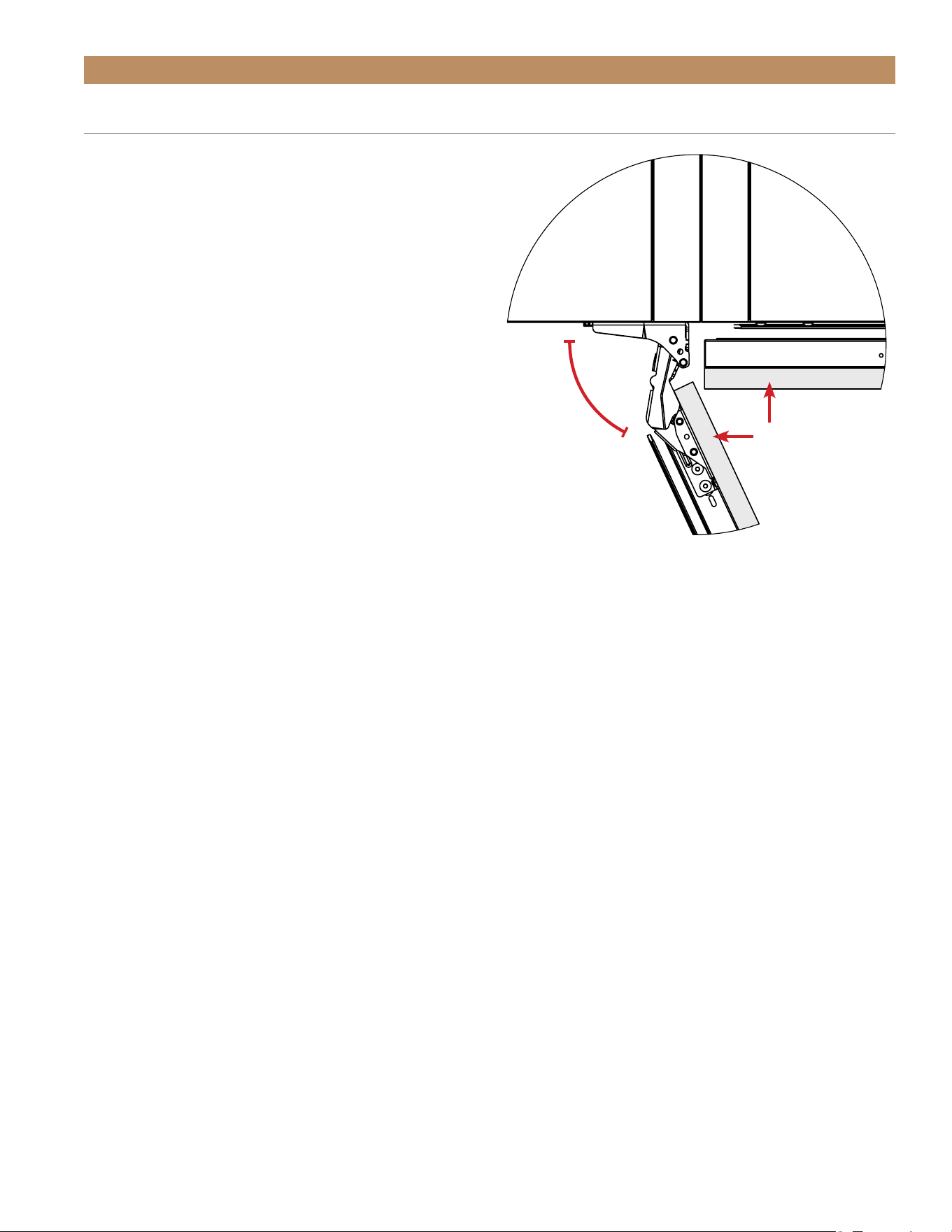
90° DOORSTOP INSTALLATION (OPTIONAL ACCESSORY)
The doorstop will restrict the door from opening past approximately 90° to prevent damage to surrounding
cabinets.
NOTE: BE SURE TO PUT A DOORSTOP PIN IN BOTH THE TOP AND BOTTOM HINGES.
SEE FIGS. 1 AND 2.
CABINET SETUP
FIG. 9.
Be sure the drawers close with the gaskets flush against the unit.
FIG. 8.
Be sure the gasket is fully seated in the gasket channel.
DRAWER OVERLAY PANEL INSTALLATION (CONT.)
FIG. 1.
Drrop the doorstop pin intop the articulated hinge.
FIG. 2.
Install a doorstop pin in both hinges.

ADA HEIGHT INSTALL GUIDETEC_TM_120 | REV. C | EN FR 07/19/2022 Page 49 of 76
CABINET COMPONENTS / ELECTRONIC CONTROL
AND LIGHT SWITCH LOCATION
ELECTRONIC CONTROL DISPLAY CODES
UNLOCK THE CONTROL
TURN OFF / ON CONTROL
CHANGE THE SET POINT
INITIATE MANUAL DEFROST
CHANGE DISPLAY READOUT
PRESERVE THE MOMENT
®
CABINET OPERATION
TRUE RESIDENTIAL
®
TEC_TM_120 | REV. C | EN FR07/19/2022Page 50 of 76
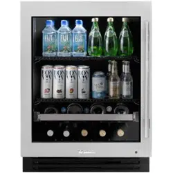
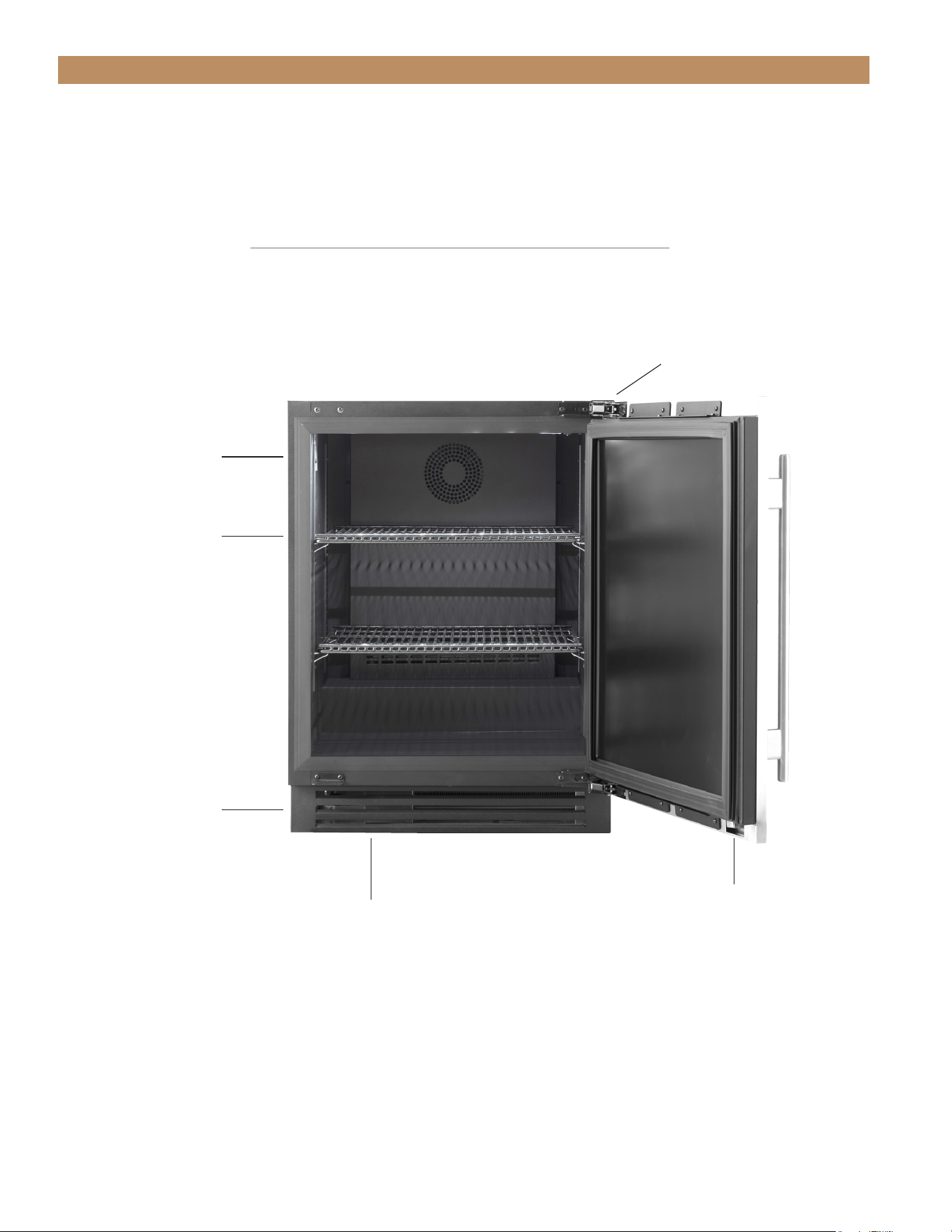
CABINET OPERATION
REFRIGERATOR / FREEZER COMPONENTS
Removable kick plate
for easy cleaning
Door Lock
Adjustable shelves (2)
Serial Label Location
Electronic Temperature Control location
behind the kickplate
Articulating Hinge
ADA HEIGHT INSTALL GUIDETEC_TM_120 | REV. C | EN FR 07/19/2022 Page 51 of 76
Door Lock
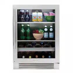
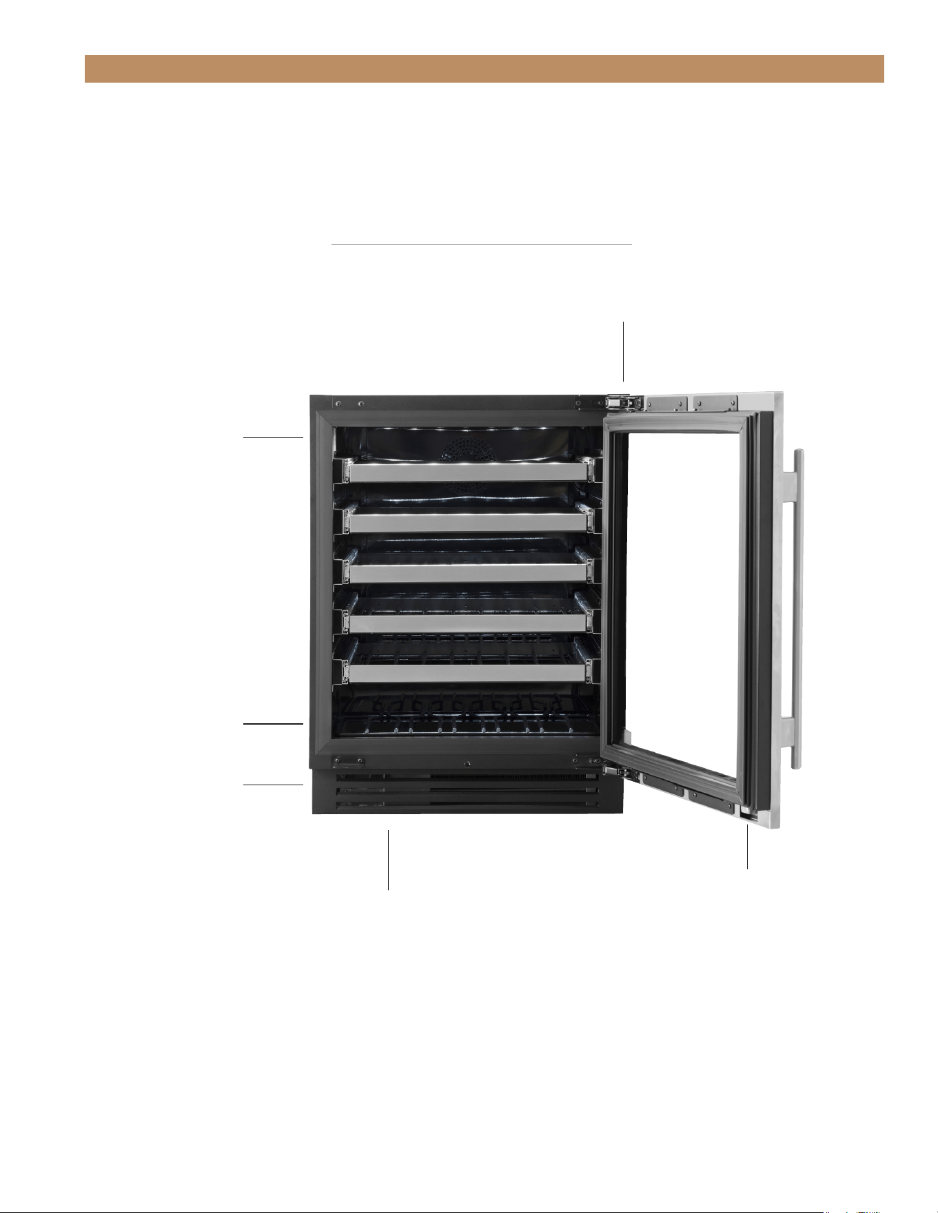
CABINET OPERATION
WINE CABINET COMPONENTS
Removable kick plate
for easy cleaning
Electronic Temperature Control location
behind the kickplate
Serial Label Location
Articulating Hinge
Floor Wine Cradle
TRUE RESIDENTIAL
®
TEC_TM_120 | REV. C | EN FR07/19/2022Page 52 of 76
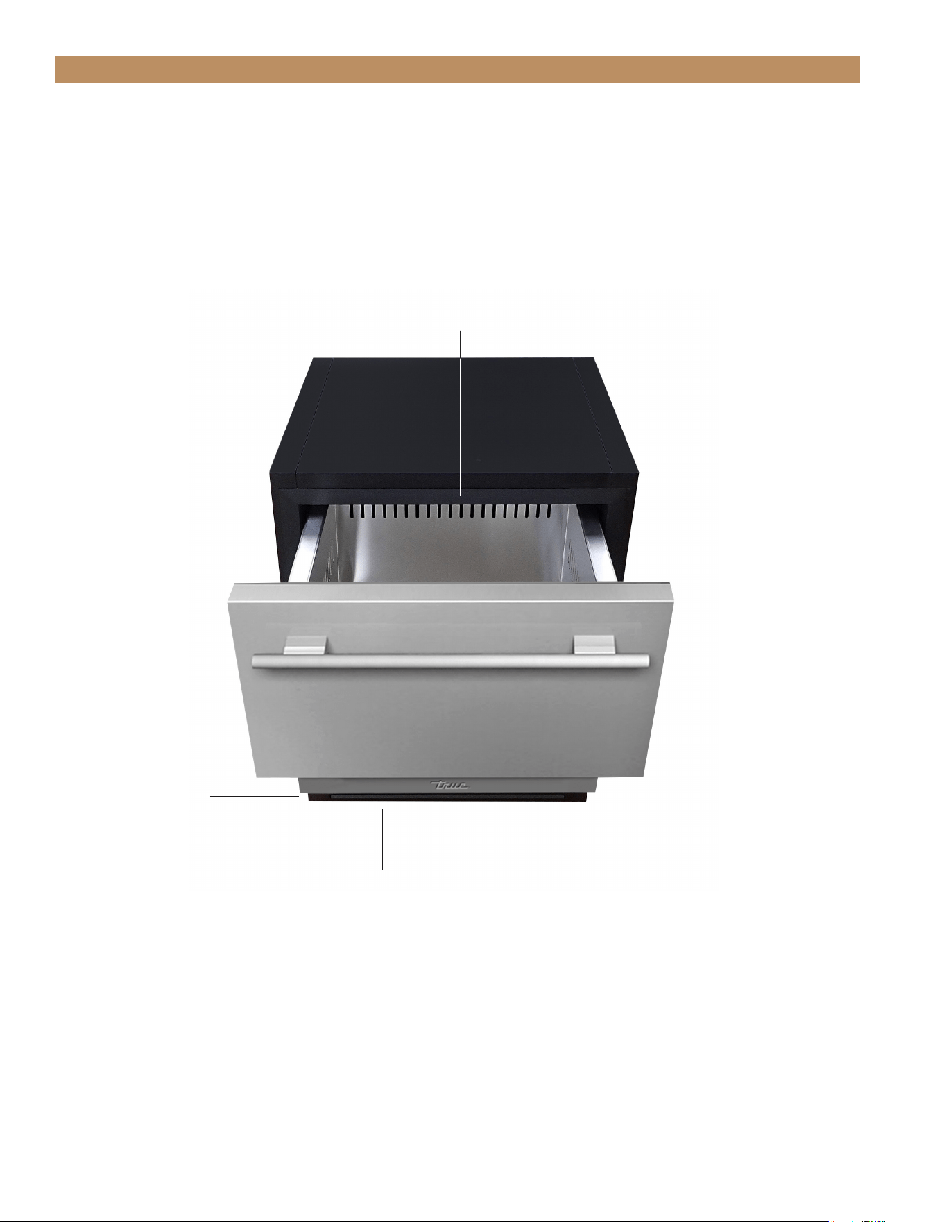
CABINET OPERATION
Removable kick plate
for easy cleaning
Electronic Temperature Control location
behind the kickplate
Serial Label
Front center ceiling
Exclusive True®-Glide
Soft-Close feature for
both drawers
REFRIGERATED DRAWERS
ADA HEIGHT INSTALL GUIDETEC_TM_120 | REV. C | EN FR 07/19/2022 Page 53 of 76
CABINET OPERATION
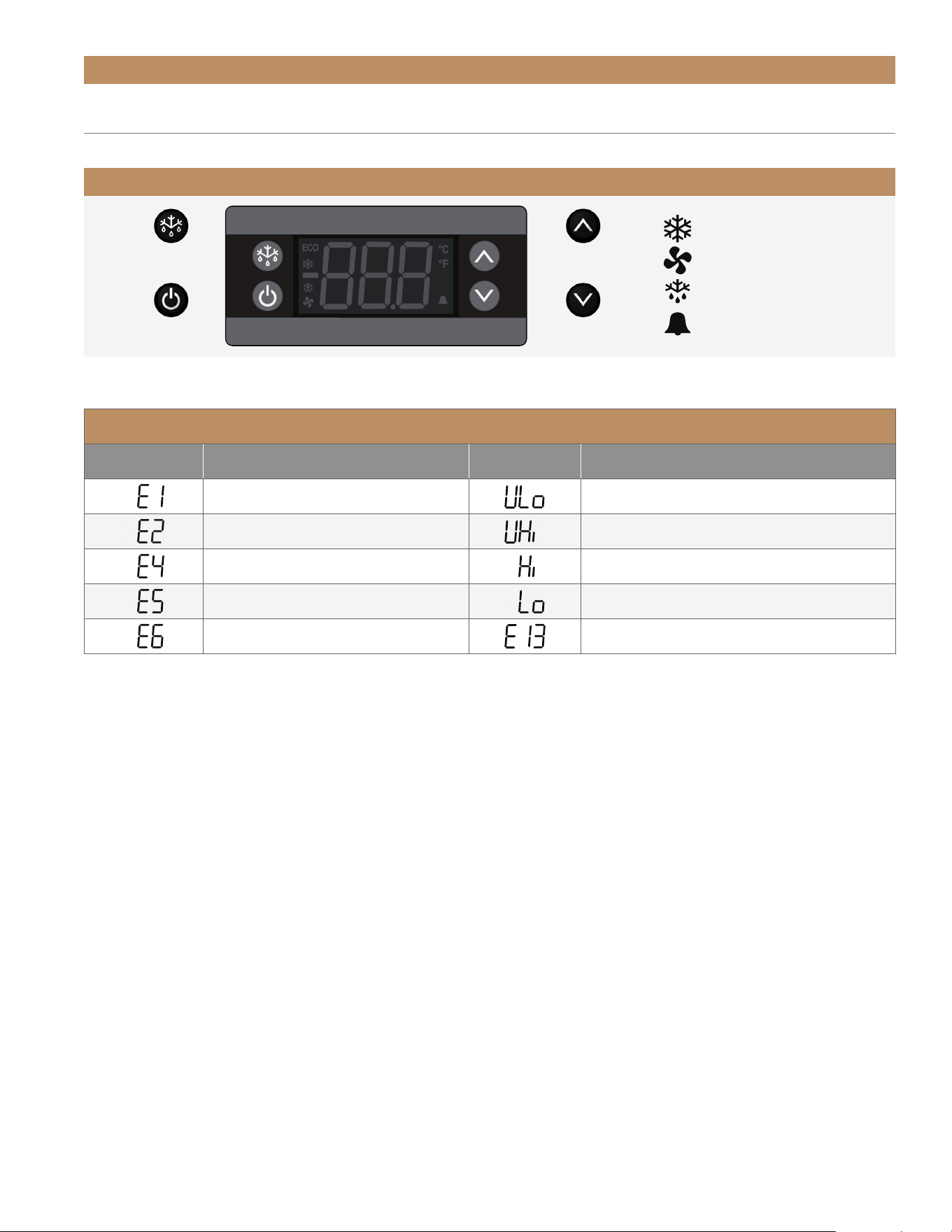
ELECTRONIC CONTROL OPERATION
Compressor Running
Evaporator Fan Running
Cabinet in Defrost
Alarm
ELECTRONIC DISPLAY CODES
Display Definition Display Definition
Sensor 1 Defect Low Supply Voltage
Sensor 2 Defect High Supply Voltage
Compressor Fault High Temperature Alarm
Heater Fault Low Temperature Alarm
Pot Fault Communication Error
ELECTRONIC CONTROL LEGEND
ECO
°C
°F
Set Point /
Up Arrow
Set Point /
Down Arrow
Defrost / Back /
Show °F or °C
Power /
Okay
TRUE RESIDENTIAL
®
TEC_TM_120 | REV. C | EN FR07/19/2022Page 54 of 76
CABINET OPERATION
ELECTRONIC CONTROL OPERATION
Compressor Running
Evaporator Fan Running
Cabinet in Defrost
Alarm
ELECTRONIC CONTROL LEGEND
ECO
°C
°F
Set Point /
Up Arrow
Set Point /
Down Arrow
Defrost / Back /
Show °F or °C
Power /
Okay
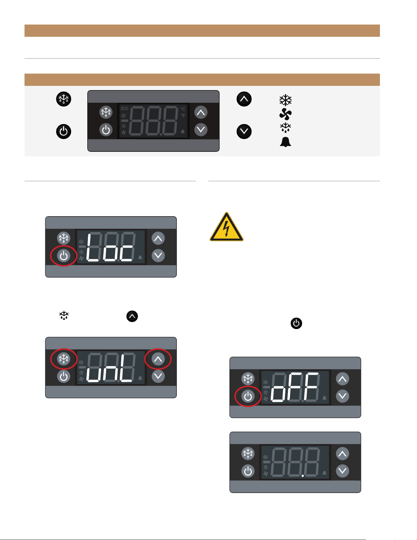
UNLOCK THE CONTROL
The display will not lock unless it was originally locked.
1. Press any button to display the current lock status.
2. If the display shows unL, the control is unlocked.
If the display shows Loc, press and hold the back
button and the up arrow until the display
shows unL.
ECO
°C
°F
ECO
°C
°F
ECO
°C
°F
ECO
°C
°F
NOTE: THE CONTROL WILL LOCK AFTER 60
SECONDS OF INACTIVITY.
TURN OFF / ON THE CONTROL
Turning off the control will deactivate all electrical
components.
CAUTION – Turning off the control will
not shut off power to the cabinet. Be
sure to remove power to the cabinet prior
to servicing.
ATTENTION – La désactivation de la
commande ne coupe pas l’alimentation
de l’armoire. Assurez-vous de couper
l’alimentation de l’armoire avant toute
intervention.
TURN OFF
Press and hold the power button until the display
shows oFF. The display will then turn blank with a
decimal point.
ADA HEIGHT INSTALL GUIDETEC_TM_120 | REV. C | EN FR 07/19/2022 Page 55 of 76
ECO
°C
°F
ECO
°C
°F
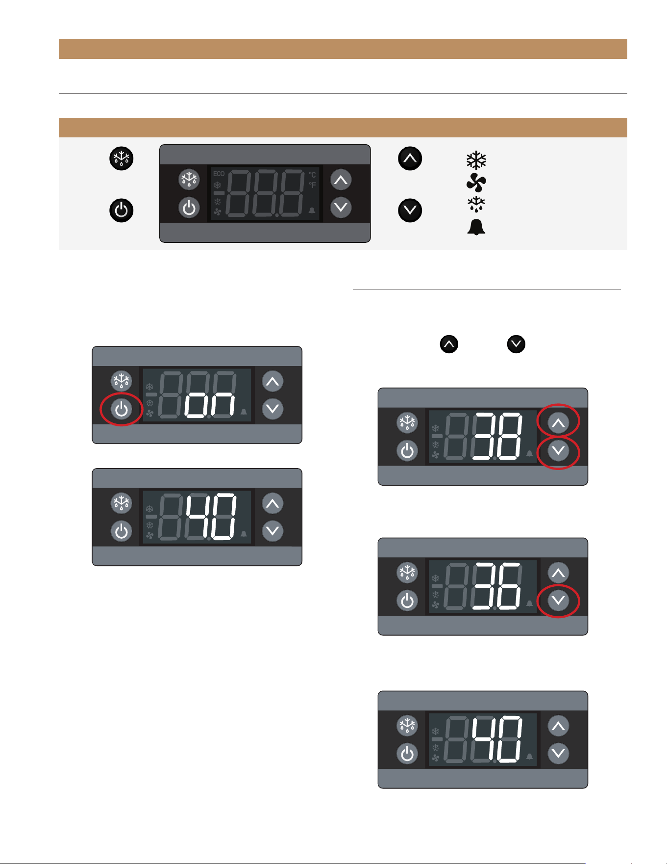
TURN ON
Press and hold the power button until the display
shows on. The display will then show the current
cabinet temperature.
CABINET OPERATION
ELECTRONIC CONTROL OPERATION
Compressor Running
Evaporator Fan Running
Cabinet in Defrost
Alarm
ELECTRONIC CONTROL LEGEND
ECO
°C
°F
Set Point /
Up Arrow
Set Point /
Down Arrow
Defrost / Back /
Show °F or °C
Power /
Okay
ECO
°C
°F
ECO
°C
°F
CHANGE THE SET POINT
Changing the set point adjusts the cabinet
temperature to keep optimal product temperature.
1. Press the up or down arrow to show the
current setting.
2. Press the arrow buttons to change the set point to
the desired temperature.
3. Leave the display inactive until it shows the
current cabinet temperature.
ECO
°C
°F
TRUE RESIDENTIAL
®
TEC_TM_120 | REV. C | EN FR07/19/2022Page 56 of 76
CABINET OPERATION
ELECTRONIC CONTROL OPERATION
Compressor Running
Evaporator Fan Running
Cabinet in Defrost
Alarm
ELECTRONIC CONTROL LEGEND
ECO
°C
°F
Set Point /
Up Arrow
Set Point /
Down Arrow
Defrost / Back /
Show °F or °C
Power /
Okay
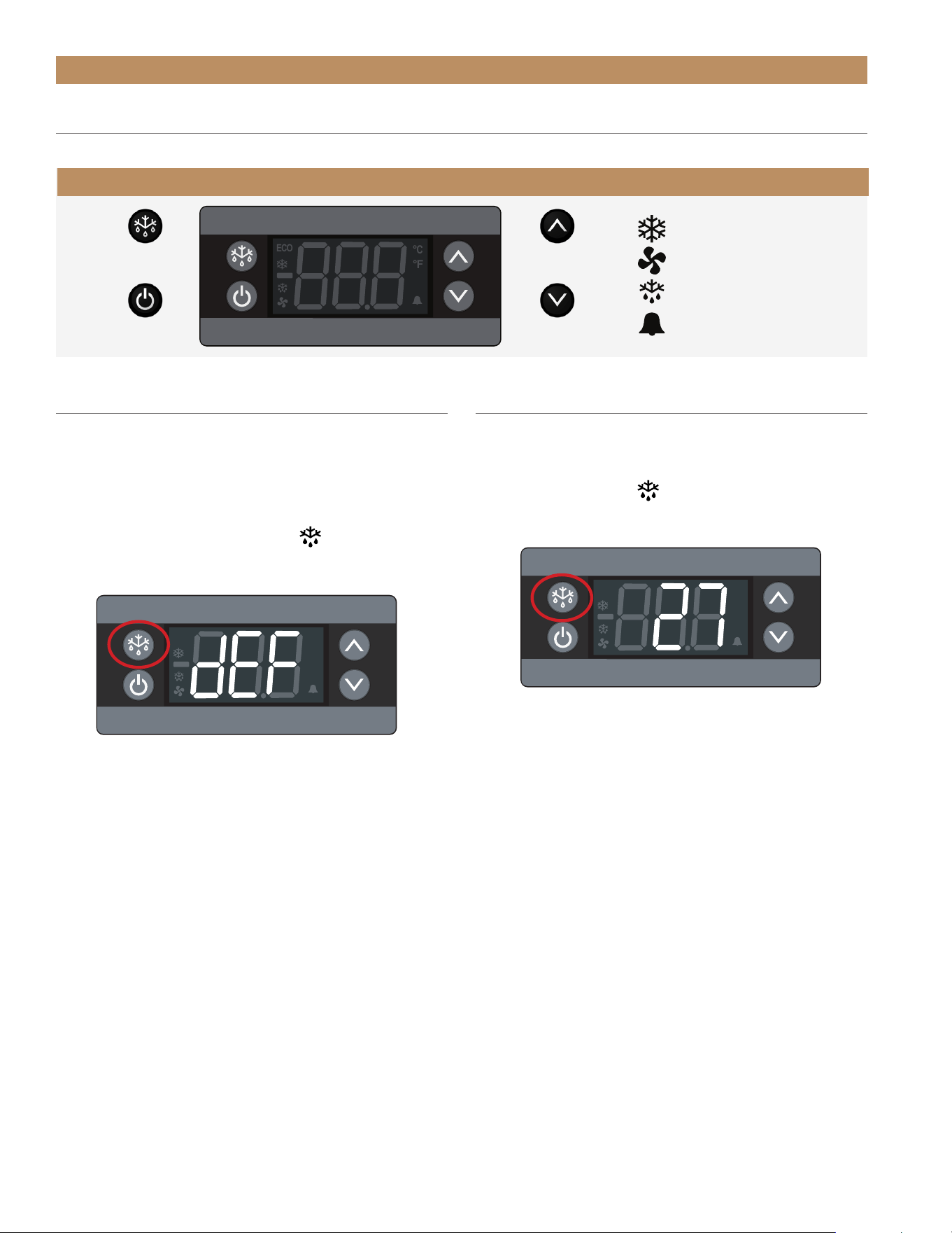
INITIATE MANUAL DEFROST
A manual defrost clears accumulated frost and ice
from the evaporator coil. The defrost will only terminate
when a specific preset temperature or duration has
been met.
Press and hold the defrost button
until the display
shows dEF.
CHANGE DISPLAY READOUT
The display can show the temperature in either
Fahrenheit or Celsius.
Press the back button
to change the system of
measure.
ECO
°C
°F
ECO
°C
°F

ADA HEIGHT INSTALL GUIDETEC_TM_120 | REV. C | EN FR 07/19/2022 Page 57 of 76
CONDENSER COIL CLEANING
CONDENSATION
HANDLE TIGHTENING
STAINLESS STEEL EQUIPMENT CARE & CLEANING
PRESERVE THE MOMENT
®
MAINTENANCE, CARE & CLEANING
TRUE RESIDENTIAL
®
TEC_TM_120 | REV. C | EN FR07/19/2022Page 58 of 76
MAINTENANCE, CARE & CLEANING
WARNING – Electrical shock or burn
hazard. Unplug the unit or turn off the
power supply before proceeding.
DO NOT clean appliance with a pressure
washer or hose.
ATTENTION – Risque d’électrocution ou
de brûlure. Débranchez l’appareil ou
coupez l’alimentation électrique avant
de continuer. Ne nettoyez pas l’appareil
avec un nettoyeur haute pression ou un
tuyau.
CAUTION – Risk of eye injury from
debris. Eye protection is recommended.
ATTENTION – Les ailettes sont
coupantes. Soyez prudent pour éviter
les lésions oculaires. Une protection des
yeux est recommandée.
CAUTION – Coil fins are sharp. Gloves
are recommended.
ATTENTION – Les ailettes de la bobine
sont tranchantes. Les gants sont
recommandés.
REQUIRED TOOLS
Required tools include (but may not be limited to) the
following:
• Gloves
• Eye Protection
• Stiff Bristle Brush
• Vacuum Cleaner
• Flashlight
• Tank of Compressed Air
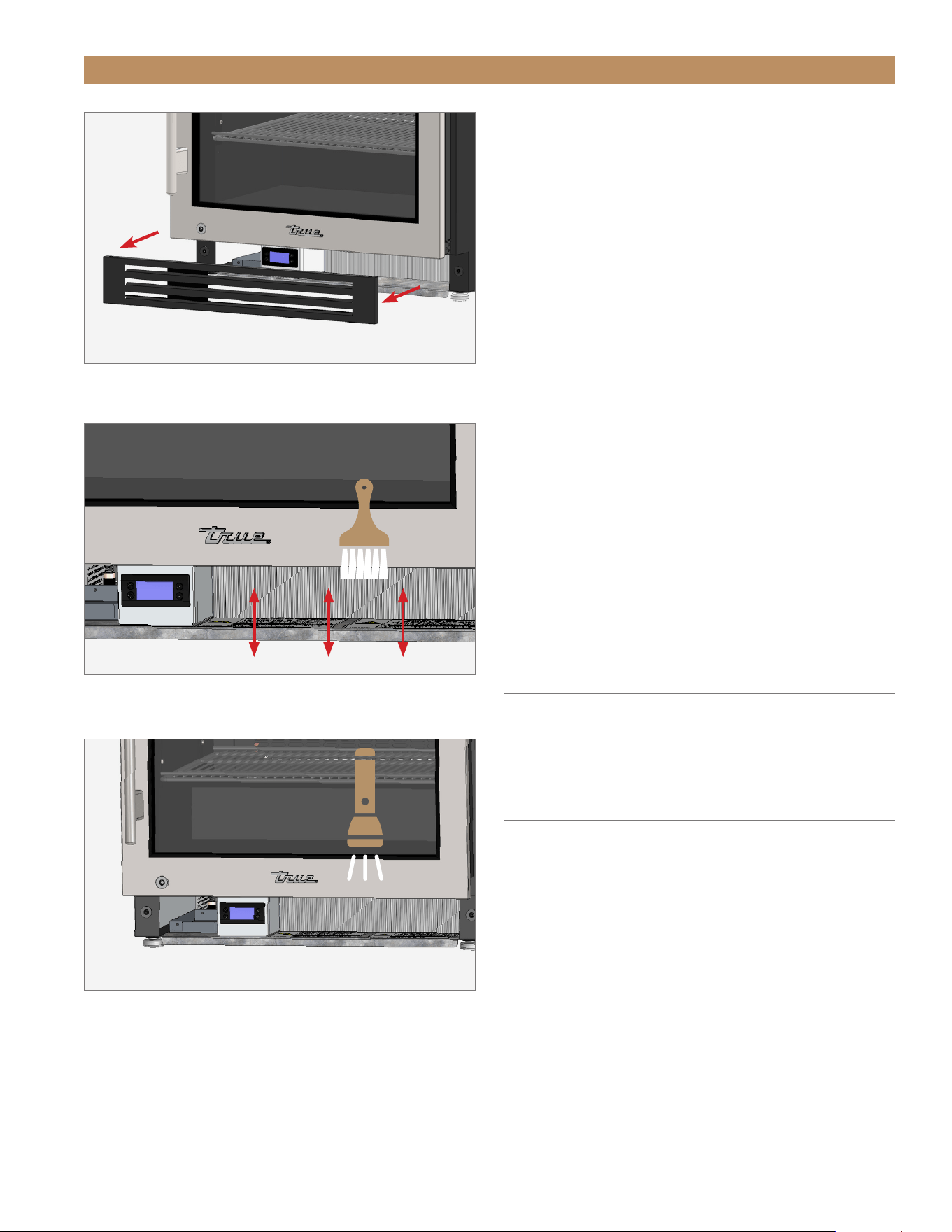
PROCEDURE
1. Remove the kickplate. See fig. 1.
2. With a stiff bristle brush, carefully clean
accumulated dirt from the front coil fins.
3. With the dirt removed from the surface of the coil,
use a flashlight to verify you can see through the
coil and observe the condenser fan blade spinning.
See fig. 3.
4. If the view is clear, reinstall the kickplate, restore
power, and verify correct operation.
5. If the view is not clear, gently blow compressed air
or CO
2
through the coil until it is clean.
6. Carefully vacuum any dirt around the condensing
unit area.
7. Reinstall the kickplate, restore power, and verify
correct operation.
CAUTION – TAKE CARE DURING OPERATION, MAINTENANCE, OR REPAIRS TO AVOID CUTS OR
PINCHING FROM ANY CABINET PART/COMPONENT.
ATTENTION – LORS DE L’UTILISATION, DE L’ENTRETIEN OU DES RÉPARATIONS, IL FAUT
PRENDRE SOIN D’ÉVITER LES COUPURES ET LES PINCEMENTS POUVANT SURVENIR AU
CONTACT DES PIÈCES OU DES COMPOSANTES DE L’ARMOIRE.
CONDENSER COIL CLEANING
Keeping the condenser coil clean minimizes required servicing and lowers electrical cost. Warranty does not cover
cleaning the condenser coil.
ADA HEIGHT INSTALL GUIDETEC_TM_120 | REV. C | EN FR 07/19/2022 Page 59 of 76
MAINTENANCE, CARE & CLEANING
FIG. 1.
Pull the kickplate off the magnets.
FIG. 2.
Never brush across the coil fins.
FIG. 3.
Verify all blockages have been removed.
IMPORTANT WARRANTY
INFORMATION
THE CLEANING OF THE CONDENSER IS NOT
COVERED BY WARRANTY!
If you have any questions, please contact your local
TRUE Manufacturing Service Department. See contact
information on pages 12, or 70.
• Condenser coils accumulate dirt and require
cleaning every 30 days or as needed.
• A dirty condenser coil can result in non-warranteed
repairs and/or cabinet failure.
• Proper cleaning involves removing dust from the
condenser by using a soft brush, vacuuming the
condenser with a shop vac, or using CO
2
, nitrogen
or pressurized air.
• Do not place any filter material in front of the
condensing coil.
IF YOU CANNOT ADEQUATELY REMOVE THE
DIRT, PLEASE CONTACT YOUR LICENSED
REFRIGERATION SERVICE PROVIDER.
CONDENSATION
Excessive condensation can be caused by leaving the
door/drawer open for long periods of time or running
the cabinet with little to no product inside.
HANDLE TIGHTENING
Tighten the handle with a 3/32” Allen wrench.

TRUE RESIDENTIAL
®
TEC_TM_120 | REV. C | EN FR07/19/2022Page 60 of 76
STAINLESS STEEL OPPONENTS
There are three basic things which can break down
your stainless steel’s passivity layer and allow corrosion
to rear its ugly head.
• Scratches from wire brushes, scrapers, and steel
pads are just a few examples of items that can be
abrasive to stainless steel’s surface.
• Deposits left on your stainless steel can leave spots.
You may have hard or soft water depending on what
part of the country you live in. Hard water can leave
spots. Hard water that is heated can leave deposits
if left to sit too long. These deposits can cause the
passive layer to break down and rust your stainless
steel. All deposits left from food prep or service
should be removed as soon as possible.
• Chlorides are present in table salt, food, and water.
Household and industrial cleaners are the worst
type of chlorides to use.
STAINLESS STEEL EQUIPMENT CARE & CLEANING
NOTICE – Do not use any steel wool, abrasive or chlorine based products to clean stainless
steel surfaces.
STAINLESS STEEL CLEANING AND
RESTORATION
Do not use stainless steel cleaners or similar solvents
to clean plastic or powder-coated parts. Instead, use
warm soapy water.
• For routine cleaning and removal of grease and
oil, apply white vinegar, ammonia, or any good
commercial detergent* with a soft cloth or sponge.
• Stainless steel polish (i.e., Zep
®
Stainless Steel
Polish, Weiman
®
Stainless Steel Cleaner & Polish,
Nyco
®
Stainless Steel Cleaner & Polish, or Ecolab
®
Ecoshine
®
) and olive oil can act as a barrier against
fingerprints and smears.
• Degreasers* (i.e., Easy-Off
®
Specialty Kitchen
Degreaser or Simple Green
®
Industrial Cleaner &
Degreaser) are excellent for removal of grease, fatty
acids, blood and burnt-on foods on all surfaces.
• For restoration/passivation or removing stubborn
stains and discoloration, Brillo
®
Cameo
®
, Zud
®
Cleanser, Ecolab
®
Specifax
™
First Impression
®
Metal Polish, Sheila Shine, or talc can be applied
by rubbing in the direction of the polish lines.
* Do not use detergents or degreasers with chlorides
or phosphates.
NOTE: THE USE OF PROPRIETARY NAMES IS
INTENDED FOR EXAMPLE ONLY AND DOES NOT
CONSTITUTE OR IMPLY AN ENDORSEMENT.
OMISSION OF PROPRIETARY CLEANSERS FROM
THIS LIST DOES NOT IMPLY INADEQUACY.
MAINTENANCE, CARE & CLEANING

ADA HEIGHT INSTALL GUIDETEC_TM_120 | REV. C | EN FR 07/19/2022 Page 61 of 76
8 TIPS TO HELP PREVENT RUST ON
STAINLESS STEEL
• Maintain the Cleanliness of Your Equipment – Avoid
build-up of hard stains by cleaning frequently. Use
cleaners at the recommended strength (alkaline
chlorinated or non-chloride).
• Use the Correct Cleaning Tools – Use non-abrasive
tools when cleaning your stainless steel products.
The stainless steel’s passive layer will not be
harmed by soft cloths and plastic scouring pads.
• Clean Along Polishing Lines – Polishing lines ("grain")
are visible on some stainless steels. Always scrub
parallel to polishing lines when visible. Use a plastic
scouring pad or soft cloth when you cannot see the
grain.
• Use Alkaline, Alkaline-Chlorinated or Non-Chloride
Cleaners – While many traditional cleaners are
loaded with chlorides, the industry is providing an
ever increasing choice of non-chloride cleaners. If
you are not sure of your cleaner’s chloride content,
contact your cleaner supplier. If they tell you that
your present cleaner contains chlorides, ask if
they have an alternative. Avoid cleaners containing
quaternary salts, as they can attack stainless steel,
causing pitting and rusting.
• Rinse – When using chlorinated cleaners, you must
rinse and wipe dry immediately. It is better to wipe
standing cleaning agents and water as soon as
possible. Allow the stainless steel equipment to air
dry. Oxygen helps maintain the passivity film on
stainless steel.
• Never Use Hydrochloric Acid (Muriatic Acid) on
Stainless Steel – Even diluted, hydrochloric acid
can cause corrosion, pitting and stress corrosion
cracking of stainless steel.
• Water Treatment – To reduce deposits, soften hard
water when possible. Installation of certain filters
can remove corrosive and distasteful elements.
Salts in a properly maintained water softener can
also be to your advantage. Contact a treatment
specialist if you are not sure of the proper water
treatment.
• Regularly Restore & Passivate Stainless Steel –
Stainless steel gets its stainless properties from
the protective chromium oxides on its surface.
If these oxides are removed by scouring, or by
reaction with harmful chemicals, then the iron in
the steel is exposed and can begin to oxidize, or
rust. Passivation is a chemical process that removes
free iron and other contaminants from the surface
of stainless steel, allowing the protective chromium
oxides to re-form.
STAINLESS STEEL EQUIPMENT CARE & CLEANING (CONT.)
MAINTENANCE, CARE & CLEANING

TRUE RESIDENTIAL
®
TEC_TM_120 | REV. C | EN FR07/19/2022Page 62 of 76
NOTES

ADA HEIGHT INSTALL GUIDETEC_TM_120 | REV. C | EN FR 07/19/2022 Page 63 of 76
SERVICING & REPLACING COMPONENTS
REVERSING DOOR
DOOR ADJUSTMENT
DRAWER ADJUSTMENT
FREQUENTLY ASKED QUESTIONS
CONTACT US
PRESERVE THE MOMENT
®
ADJUSTMENTS, SERVICING & REPLACING COMPONENTS

TRUE RESIDENTIAL
®
TEC_TM_120 | REV. C | EN FR07/19/2022Page 64 of 76
ADJUSTMENTS, SERVICING & REPLACING COMPONENTS
SERVICING & REPLACING
COMPONENTS
NOTE: ANY CABINET ADJUSTMENTS ARE TO
BE MADE AFTER THE CABINET HAS BEEN
VERIFIED LEVEL AND PROPERLY SUPPORTED.
• Replace component parts with original equipment
manufacturer (OEM) components.
• Contact the dealer or our parts department at
844-849-6179 or TrueResidentialParts@truemfg.com
for replacement parts.
• Have a licensed service provider service your unit
to minimize the risk of possible ignition due to
incorrect parts or improper service and to ensure
the operator’s health and safety.
• Unplug the refrigerator/freezer before cleaning or
making any repairs. Powering off an electronic
control may not remove power from all components
(e.g., light circuits, perimeter heaters, and
evaporator fans).
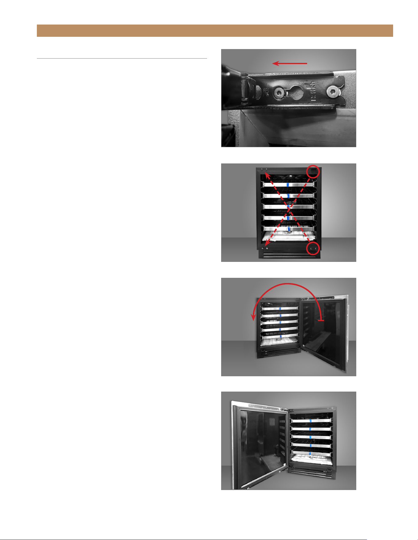
ADA HEIGHT INSTALL GUIDETEC_TM_120 | REV. C | EN FR 07/19/2022 Page 65 of 76
ADJUSTMENTS, SERVICING & REPLACING COMPONENTS
REVERSING DOOR
REQUIRED TOOLS
• 1/8" Hex Head Allen Wrench
• Drill (Optional)
PROCEDURE
1. Loosen the hinge bolts and remove the door
See fig. 1.
NOTE: DO NOT REMOVE THE HINGES FROM
THE DOOR.
2. Move the remaining hardware to the opposite
corners. See fig. 2.
NOTE: THE DOOR LOCK POSITION IS
DIFFERENT FOR EACH SIDE.
LEFT-HINGED: BOTTOM RIGHT CORNER;
RIGHT-HINGED: UPPER LEFT CORNER.
3. Rotate the door 180° and secure it to the cabinet.
See figs. 3 and 4.
4. Verify the door closes correctly and the gasket
seals without gaps.
FIG. 1.
Do not remove the hinge bolts.
FIG. 2.
Be sure to move the hardware to the opposite corners.
FIG. 3.
Rotate the door 180° and install.
FIG. 4.
Completed installation.
180°
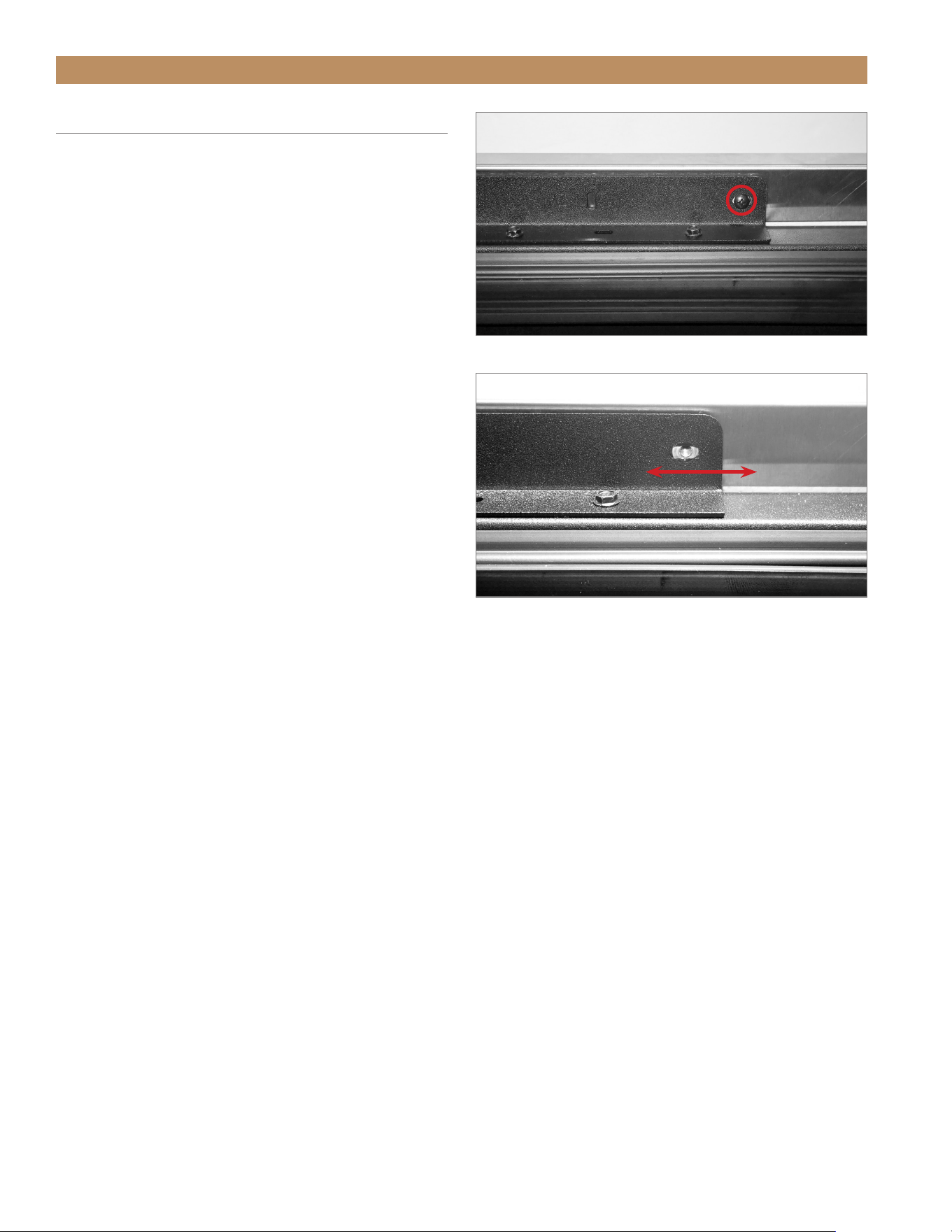
TRUE RESIDENTIAL
®
TEC_TM_120 | REV. C | EN FR07/19/2022Page 66 of 76
ADJUSTMENTS, SERVICING & REPLACING COMPONENTS
DOOR ADJUSTMENT
Door skin bracket screw holes are slotted to assist with
door adjustment. See figs. 1 and 2.
PROCEDURE
1. Loosen the screws securing the door skin / panel
to the door skin bracket. See fig. 1.
NOTE: DO NOT REMOVE THE SCREWS.
2. Adjust the door skin / panel as needed. See fig. 2.
3. Tighten the door skin bracket screws.
4. Verify door skin / panel alignment. Repeat steps
1-3 as needed. procedure
FIG. 1.
Door skin bracket screw location. Not all locations shown.
FIG. 2.
Bracket screw holes are slotted for easy adjustment. Screw
removed for illustration.
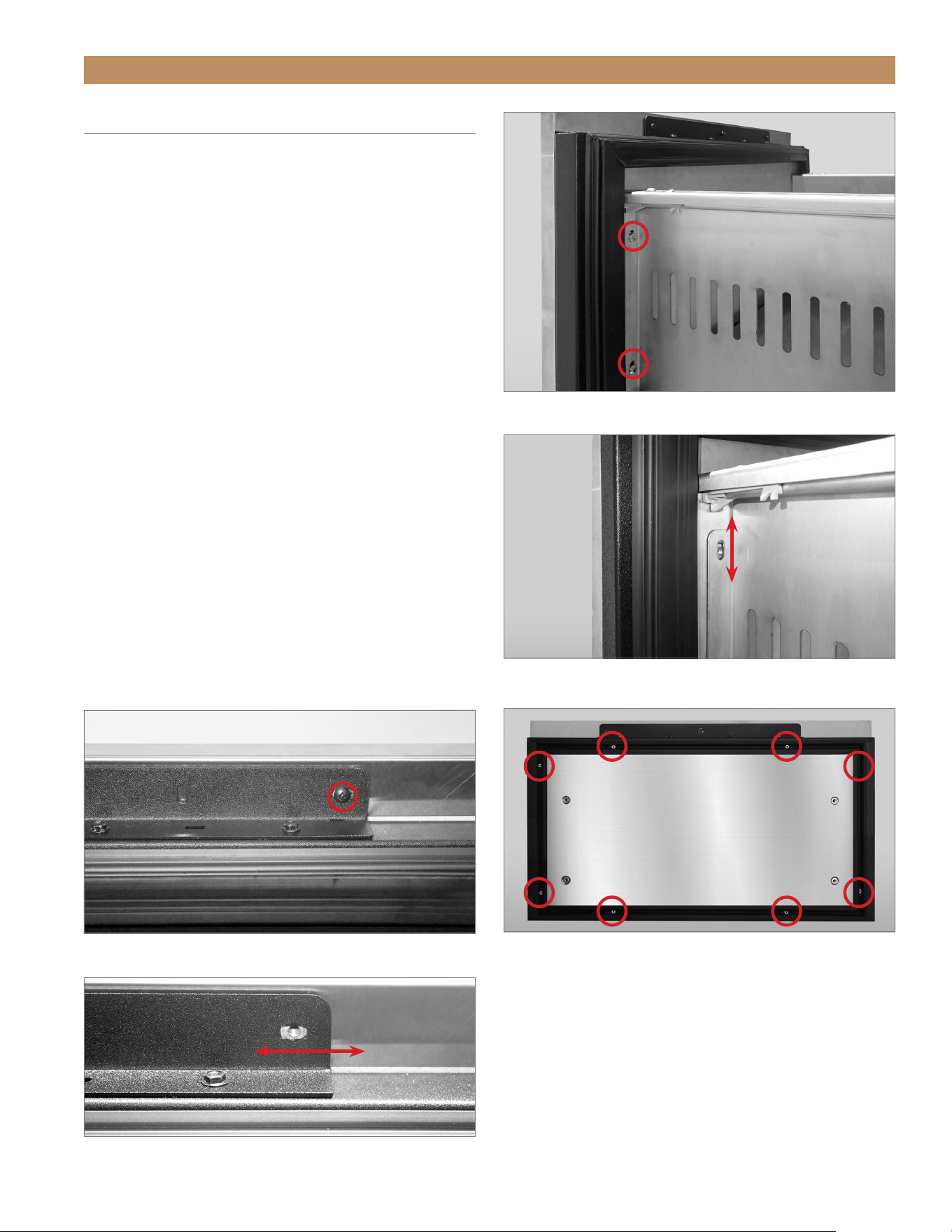
ADA HEIGHT INSTALL GUIDETEC_TM_120 | REV. C | EN FR 07/19/2022 Page 67 of 76
ADJUSTMENTS, SERVICING & REPLACING COMPONENTS
DRAWER ADJUSTMENT
Drawer front bracket and skin bracket screw holes are
slotted to assist with drawer adjustment. See figs. 1-4.
PROCEDURE
1. Loosen the drawer front bracket screws. See fig. 1.
2. Adjust the drawer front as needed. See fig. 2.
3. Tighten the drawer front bracket screws.
4. Verify drawer alignment. If more alignment is
needed, continue to steps 5 and 6.
5. Loosen the screws securing the drawer skin to the
drawer skin bracket. See fig. 3.
NOTE: IF APPLICABLE, REMOVE ANY
DRAWER SKIN / BRACKET SCREWS GOING
THROUGH THE DRAWER FRONT. SEE FIG.
4.
6. Adjust the drawer skin/panel as needed. See fig. 5.
7. Tighten the drawer skin bracket screws.
NOTE: REINSTALL ANY DRAWER FRONT
SCREWS REMOVED IN STEP 5.
FIG. 1.
Drawer front bracket screw locations. Other side not shown.
FIG. 3.
Drawer skin bracket screw location. Not all locations shown.
FIG. 5.
Bracket screw holes are slotted for easy adjustment. Screw
removed for illustration.
FIG. 2.
Bracket screw holes are slotted for easy adjustment. Screw
removed for illustration.
FIG. 4.
Drawer front screw locations.
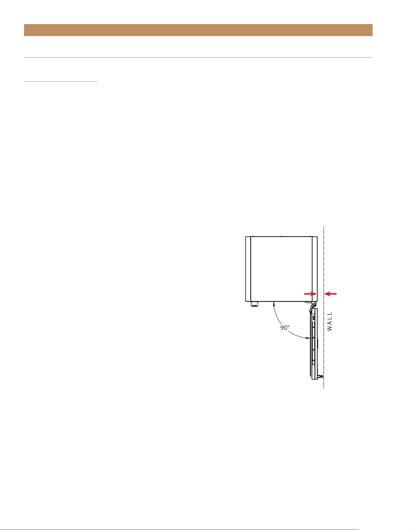
TRUE RESIDENTIAL
®
TEC_TM_120 | REV. C | EN FR07/19/2022Page 68 of 76
UNDERCOUNTER
How do I adjust the temperature?
Please see "Change the Set Point" (page 55).
Why does the evaporator fan motor constantly run?
This is normal. The evaporator fan motor runs
continuously to ensure even temperature throughout
your cabinet. The fan only stops when the door is
opened to prevent warm air from being circulated
throughout the cabinet.
Why isn’t my unit cooling correctly?
Check for any obstructions to the condenser coil
(located behind the kickplate). Confirm the area
around the condenser coil is clean.
How do I adjust or remove shelving?
Please see "Shelf Installation" (page 40).
Why is there warm air coming from the bottom/front
of the unit at the kickplate?
This is normal. The heat from the compressor is blown
out through the kickplate.
Why is there condensation forming on the inside/
outside of the unit?
Condensation can form when the door is left open for
a long period of time or the unit runs with little to no
product inside. Moisture can also form on applications
installed side-by-side or on sides with 0" clearance;
to prevent this, leave at least a 5/8" (1.58 cm) gap
between the cabinets, or install foam pads between
the cabinets and on any side with 0" clearance. To
order foam pads, contact our parts department at
844-849-6226 or TrueResidentialParts@TrueMfg.com.
How much clearance is needed to have the hinges
next to the wall and still allow the door to open 90°?
2" (51 mm)
FREQUENTLY ASKED QUESTIONS
ADJUSTMENTS, SERVICING & REPLACING COMPONENTS
1-7/8"

ADA HEIGHT INSTALL GUIDETEC_TM_120 | REV. C | EN FR 07/19/2022 Page 69 of 76
FREQUENTLY ASKED QUESTIONS (CONT.)
Can I put units flush against each other without
spacing?
In areas with typical climate-controlled temperature/
humidity, yes, True cabinets can be installed side-by-
side without spacing. However, in humid, non-climate
controlled areas, be sure to leave at least a 5/8"
(1.58 cm) gap between the cabinets, or install foam
pads between the cabinets and on any side with 0"
clearance, to prevent moisture from developing. To
order foam pads, contact our parts department at
844-849-6226 or TrueResidentialParts@TrueMfg.com.
Does True sell wooden overlay doors?
No, True does not. For wooden overlay doors, reach
out to a cabinetmaker and provide the overlay
template available in our document library:
http://www.true-residential.com/support/document-library.
Do True units have zero clearance hinges?
Yes, the unit can be installed flush with adjoining
cabinetry and still open fully.
What is the decibel rating of the units?
42-47 dB.
I don’t see a service company in my area.
Who can I call?
Please contact True Residential Service at
888-616-8783 or info@true-residential.com for
assistance finding an appropriate service provided.
ADJUSTMENTS, SERVICING & REPLACING COMPONENTS
Does my unit have to be covered outdoors?
It is recommended that units are installed in a covered
application. All True undercounter units are UL rated
for outdoor use. If left exposed to the elements
throughout the winter, a cover will help preserve the
life and beauty of your True unit. Please see "Outdoor
Use" (page 13) for more detail.
What should I do in the winter? Do I have to bring
the unit inside? How cold can the weather get before
it’s a problem?
When the temperature consistently reaches 32°F
(0°C), remove all product from the unit and unplug or
turn the unit off. If the unit is exposed to the elements,
covering the unit extends its life and beauty.
WINE CABINET
Can I store magnum bottles?
Yes, up to five magnums can fit on the floor rack.
Can I store Pinot/Bordeaux/Riesling bottles?
Yes, nearly all bottle varieties fit in your True Wine
Cabinet.
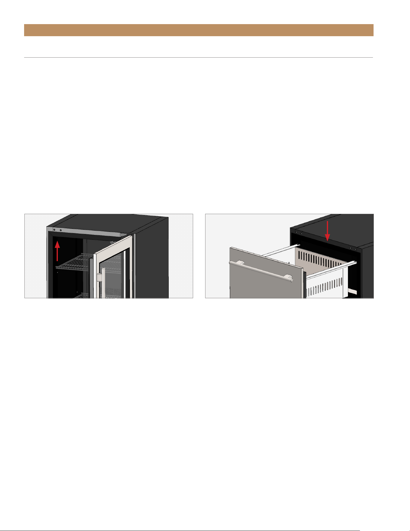
TRUE RESIDENTIAL
®
TEC_TM_120 | REV. C | EN FR07/19/2022Page 70 of 76
CONTACT INFORMATION
For any questions about installation, please contact your TRUE dealer or TRUE Residential Technical Service.
Please have your model and serial number (see serial label location below) available so we can better assist you
with your service – or parts-related inquiries.
CUSTOMER SERVICE
Phone: 888-616-8783
info@true-residential.com
TECHNICAL SERVICE DEPARTMENT
Phone: 844-746-9423
TrueResidentialService@truemfg.com
WARRANTY DEPARTMENT
Phone: 844-849-6179
TrueResidentialWarranty@truemfg.com
CONTACT US
SERIAL LABEL LOCATION
Your serial label contains important information such as your model name and serial number. Label location varies
by model type.
FIG. 1.
Door units: upper left interior wall.
FIG. 2.
Drawer units: front center interior ceiling.

ADA HEIGHT INSTALL GUIDETEC_TM_120 | REV. C | EN FR 07/19/2022 Page 71 of 76
ADA TRUE RESIDENTIAL
®
WARRANTY STATEMENT
TWO-YEAR PARTS & LABOR WARRANTY
TRUE
®
warrants to the original purchaser of every new TRUE refrigerated unit, the cabinet and all parts thereof, to be free from defects in material or
workmanship under normal and proper use and maintenance as specified by TRUE and upon proper installation and start-up in accordance with the
instruction packet supplied with each TRUE unit. TRUE’s obligation under this warranty is limited to a period of two (2) years from the date of original
installation. Any warranty coverage is dependent on the purchase date of the cabinet being within 27 months of the original ship date from TRUE.
ADDITIONAL THREE-YEAR COMPRESSOR WARRANTY
In addition to the Two (2) year warranty stated above, TRUE warrants its hermetically and semi-hermetically sealed compressor to be free from defects in both
material and workmanship under normal and proper use and maintenance service for a period of three (3) additional years the date of original installation. Any
part covered under this warranty that is determined by TRUE to have been defective within this time frame, is limited to the repair or replacement, including
labor charges, of defective parts or assemblies. Compressors determined by TRUE to have been defective within this extended time period will, at TRUE’s
option, be either repaired or replaced with a compressor or compressor parts of similar design and capacity. The three (3) year extended compressor warranty
applies only to hermetically and semi-hermetically sealed parts of the compressor and does not apply to any other parts or components, including, but not
limited to: cabinet, paint finish, temperature control, refrigerant, metering device, driers, motor starting equipment, fan assembly or any other electrical
component, etcetera.
COMPRESSOR WARRANTY
The three (3) year compressor warranty detailed above will be voided if the following procedure is not carefully adhered to:
1. This system contains R600 refrigerant and polyol ester lubricant. The polyol ester lubricant has rapid moisture absorbing qualities. If long exposure to
the ambient conditions occur, the lubricant must be removed and replaced with new. For oil amounts and specifications please call TRUE technical service
department (855-372-1368). Failure to comply with recommended lubricant specification will void the compressor warranty.
2. Drier replacement is very important and must be changed when a system is opened for servicing. An OEM exact replacement should be used. The new drier
must also be the same capacity as the drier being replaced.
3. Micron level vacuums must be achieved to ensure low moisture levels in the system. 500 microns or lower must be obtained
DISPLAY PRODUCTS
True Residential Products on showroom display that are sold more than 2 years and 3 months (27 months) from the invoice date to the dealer would carry a
1 year parts and labor warranty, along with an additional 2 year compressor, parts only warranty.
TERMS APPLICABLE TO EACH WARRANTY
Any part covered under the above warranties that is determined by TRUE to have been defective within the time frame is limited to the repair or replacement,
including labor charges, of defective parts or assemblies. The labor warranty shall include standard straight time labor charges only and reasonable travel time,
as determined by TRUE.
WARRANTY CLAIMS
All claims for labor or parts must be made directly through TRUE. All claims should include: model number and serial number of cabinet, proof of purchase,
and date of installation. In case of warranted compressor, the compressor model tag must be returned to TRUE along with the above listed information. Any
action for breach of these warranty provisions must be commenced within three (3) months of the defect giving rise to the breach.
WHAT IS NOT COVERED BY THIS WARRANTY
TRUE’s sole obligation under this warranty is limited to either repair or replacement of parts, subject to the additional limitations below. This warranty neither
assumes nor authorizes any person to assume obligations other than those expressly covered by this warranty.
NO CONSEQUENTIAL DAMAGES
TRUE is not responsible for economic loss, profit loss; or special, indirect or consequential damages, including without limitation, losses or damages arising
from food or product spoilage claims whether or not on account or refrigeration failure.
WARRANTY IS NOT TRANSFERABLE
This warranty is not assignable and applies only in favor of the original purchaser/user to whom delivered. Any such assignment or transfer shall void the
warranties herein made and shall void all warranties, express or implied, including any warranty or merchantability or fitness for a particular purpose.
IMPROPER USAGE
TRUE assumes no liability for parts or labor coverage for component failure or other damages resulting from improper usage or installation or failure to clean
and/or maintain product as set forth in the warranty packet provided with the unit.
ALTERATION OR NEGLECT
TRUE is not responsible for the repair or replacement of any parts that TRUE determines have been subjected after the date of manufacture to alteration,
neglect, abuse, misuse, accident, damage during transit or installation, fire, flood, or act of God.
IMPROPER ELECTRICAL CONNECTIONS
TRUE is not responsible for the repair or replacement of failed or damaged components resulting from electrical power failure, high or low voltage, use of
extension cords, or improper grounding of the unit.
YOUR RIGHTS UNDER STATE LAW
This warranty gives you specific legal rights and you may have other rights that vary from state to state. Some states do not allow the exclusion or limitation of
consequential damages or a limitation on how long an implied warranty lasts, so the above exclusion or limitation may not apply to you.
ENVIRONMENTAL ATTRIBUTES
Any and all environmental attributes, including environmental offset credit rights, with respect to TRUE refrigeration units manufactured after September 1,
2015, shall remain the property of TRUE Manufacturing Co., Inc. and are not transferred.
OUTSIDE U.S./CANADA
This warranty does not apply to, and TRUE is not responsible for, any warranty claims made on products sold or used outside the United States or Canada.
SUBMIT WARRANTY CLAIMS TO: True Residential
2001 East Terra Lane
O’Fallon MO 63366
180924_DF_12.21 API#2480

TRUE RESIDENTIAL
®
TEC_TM_120 | REV. C | EN FR07/19/2022Page 72 of 76
DÉCLARATION DE GARANTIE POUR ADA TRUE RESIDENTIAL
®
GARANTIE DE DEUX ANS PIÈCES ETMAIN-D’OEUVRE
TRUE garantit à l’acheteur original de chaque nouvelle unité de réfrigération TRUE, l’armoire et toutes les parties de celle-ci, contre toute défectuosité de matériel
ou de fabrication, selon des conditions d’ utilisation normale et correcte et un service d’entretien, comme spécifié par TRUE, ainsi qu’une installation correcte et un
démarrage en conformité avec le paquet d’instructions fournit avec chaque appareil TRUE. L’obligation de TRUE dans le cadre de cette garantie est limitée à une
période de deux (2) ans à compter de la date d’installation d’origine Toute couverture de garantie dépend de la date d’achat de l’armoire dans les 27 mois suivant la
date d’expédition originale de TRUE.
GARANTIE SUPPLÉMENTAIRE DE TROIS SUR LE COMPRESSEUR
En plus du deux (2) ans de garantie indiquée ci-dessus, TRUE garantit ses compresseurs hermétiques et semi-hermétiques contre toute défectuosité de matériel ou
de fabrication selon une utilisation correcte et un entretien régulier pour une période de trois (3) ans supplémentaires, à compter de la date d’installation originale,
Toute pièce couverte par la garantie ci-dessus et qui est considérée par TRUE comme défectueuse dans les délais prescrit peut être réparée ou remplacée, y compris
les frais de main-d’œuvre, des pièces ou sous-ensembles défectueux. Tout compresseur, déterminé selon TRUE, avoir été défectueux pendant cette période de
garantie prolongée sera, à la discrétion de TRUE, réparé ou remplacé par un compresseur ou par des pièces de compresseur qui sont d’une conception et d’une
capacité semblables. La garantie supplémentaire de trois ans (3) sur le compresseur ne s’applique qu’aux pièces hermétiques et semi-hermétiques du compresseur
et ne s’applique pas aux autres pièces ou composants, y compris, mais sans s’y limiter : armoire, peinture de finition, contrôle de température, lubrifiant de
réfrigérant, dispositif de mesure, séchoirs, appareil de démarrage du moteur, ventilateur ou tout autre composant électrique, etc.
GARANTIE SUR LE COMPRESSEUR
La garantie de trois (3) ans sur le compresseur mentionnée ci-dessus sera annulée si la procédure suivante n’est pas scrupuleusement respectée:
1. Ce système contient du frigorigène R600 et du lubrifiant à base d’ester de polyol. Le lubrifiant à base d’ester de polyol possède des qualités d’absorption
d’humidité rapide. Si ce produit est exposé à des conditions ambiantes pour une période prolongée, le lubrifiant doit être enlevé et remplacé par un nouveau. Pour
les quantités d’huile et les spécifications, prière d’appeller le service technique TRUE (855-372-1368). Tout défaut de se conformer aux spécifications de lubrifiant
recommandé annulera la garantie du compresseur.
2. Le remplacement du séchoir est très important et doit être changé lorsqu’un système est ouvert pour l’entretien. Un remplacement OEM exact devrait être utilisé.
Le nouveau séchoir doit également être de la même capacité que celle du séchoir original.
3. Une aspiration de niveau micron doit être réalisée pour assurer des niveaux faibles d’humidité dans le système. 500 microns ou moins doivent être obtenus.
PRODUITS D’AFFICHAGE
Les produits True Residential exposés en salle d’exposition qui sont vendus plus de 2 ans et 3 mois (27 mois) après la date de facturation au concessionnaire
bénéficient d’une garantie d’un an sur les pièces et la main-d’œuvre, ainsi que d’une garantie supplémentaire de 2 ans sur le compresseur, pièces uniquement.
CONDITIONS APPLICABLES À CHAQUE GARANTIE
Toute pièce couverte par les garanties ci-dessus et qui est considérée par TRUE comme défectueuse dans les délais prescrit peut être réparée ou remplacée, y
compris les frais de main-d’œuvre, des La garantie de la main d’oeuvre inclut le travail à taux normal seulement et le temps de déplacement raisonnable, déterminé
selon le fabricant TRUE.
RÉCLAMATION(S) SUR LA GARANTIE
Toutes les réclamations de la main-d’œuvre ou des pièces doivent se faire directement auprès de TRUE. Toutes les réclamations doivent inclure : le numéro de
modèle et le numéro de série de l’armoire, une preuve d’achat, et la date d’installation. Dans le cas d’une réclamation sur la garantie du compresseur, l’étiquette de
modèle du compresseur doit être retournée chez TRUE avec les informations ci-dessus énumérées. Toute action pour violation de ces dispositions de garantie doit
être engagée dans les trois (3) mois suivant le défaut donnant lieu à la violation.
CE QUI N’EST PAS COUVERT SOUS LA GARANTIE
La seule obligation de TRUE en vertu de cette garantie se limite à la réparation ou au remplacement des pièces, sous réserve des limitations supplémentaires ci-
dessous. Cette garantie n’assume ni n’autorise aucune personne à assumer des obligations autres que celles qui sont expressément couvertes sous cette garantie.
AUCUN DOMMAGES CONSÉCUTIF OU INDIRECT
TRUE n’est pas responsable des pertes financières, de la perte de profits ni de dommages consécutifs ou indirects, y compris et sans limitation, les pertes ou
dommages provenant des réclamations de détérioration des aliments ou produits, associées ou non à la défaillance de la réfrigération.
LA GARANTIE N’EST PAS TRANSFÉRABLE
Cette garantie n’est pas transférable et s’applique uniquement en faveur de l’acheteur/utilisateur initial auquel l’appareil est livré. Toute cession ou tout transfert
annule les garanties des présentes ainsi que toutes les garanties explicites ou implicites, y compris toute garantie de valeur marchande ou d’adéquation à un usage
particulier.
UTILISATION INCORRECTE
TRUE n’assume aucune responsabilité pour la couverture de pièces ou de main-d’œuvre en cas de panne de composant ou autres dommages résultant d’un usage
abusif, d’une installation incorrecte ou d’un défaut de nettoyage ou d’entretien du produit selon les conditions du manuel d’utilisation fourni avec l’appareil.
MODIFICATION OU NÉGLIGENCE
TRUE n’est pas responsable pour la réparation ou le remplacement des pièces qui sont déterminées par TRUE, d’avoir été soumis, après la date de fabrication, à
une altération, négligence, abus, usure impropre, accident, dommages lors du transport ou de l’installation, incendie, inondation ou événement de force majeure.
MAUVAIS RACCORDEMENT ÉLECTRIQUE
TRUE n’est pas responsable de la réparation ni du remplacement des composants en panne ou endommagés à la suite d’une panne d’alimentation électrique, de
tension trop haute ou trop basse, d’utilisation de rallonges ou de mise à la terre incorrecte de l’appareil.
VOS DROITS SELON LA LÉGISLATION APPLICABLE
Cette garantie vous accorde des droits juridiques particuliers et vous pouvez disposer d’autres droits selon l’état où vous vous trouvez. Certains états n’autorisent
pas l’exclusion ou la limitation des dommages indirects ou une limitation de durée sur une garantie implicite; il est donc possible que les présentes exclusions ou
limitations ne s’appliquent pas à vous.
CARACTÉRISTIQUES ENVIRONNEMENTALES
Toutes les caractéristiques environnementales, y compris les droits aux crédits de compensation environnementale, concernant les appareils de réfrigération TRUE
®
fabriqués après le 1
er
septembre 2015 demeurent la propriété de True Manufacturing Co., Inc. et ne sont pas transférés.
À L’EXTÉRIEUR DES ÉTATS-UNIS/CANADA
Cette garantie ne s’applique pas aux, et TRUE n’est pas responsable d’autres garanties portant sur les produits vendus ou utilisés en dehors des États-Unis ou le
Canada.
ENVOYEZ LES RECOURS EN GARANTIE À: True Residential
2001 East Terra Lane
O’Fallon MO 63366
181876_BP_12.21 API#2480

ADA HEIGHT INSTALL GUIDETEC_TM_120 | REV. C | EN FR 07/19/2022 Page 73 of 76
NOTES

TRUE RESIDENTIAL
®
TEC_TM_120 | REV. C | EN FR07/19/2022Page 74 of 76
NOTES

ADA HEIGHT INSTALL GUIDETEC_TM_120 | REV. C | EN FR 07/19/2022 Page 75 of 76
NOTES

TRUE RESIDENTIAL
®
07/19/2022 TEC_TM_120 | REV. C | EN FR
BP_178 8 65_01.22
CONTACT US
true-residential.com
636.240.2400
|
toll free 888.616.8783