
CRYSTAL BAY
SHOWER SYSTEMS
Installation Guide
and Users Manual
SHOWER SYSTEMS WITH RAINSYNC
Installation Guide and User Manual
1.0.1

WARNING: This product can expose you to chemicals including
nickel, which is known to the State of California to cause cancer.
For more information, go to www.P65Warnings.ca.gov.
We continually strive to improve our products. We may
change our specifications and design without prior notice.

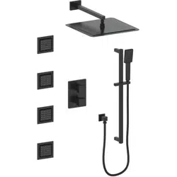
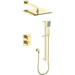
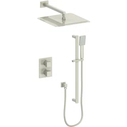
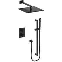
Sourced with materials from across the world, ZLINE’s shower systems
are easy to operate, reduce water waste, and complement bathroom
décor. This exclusive collection blends modern technology with traditional
appeal — offering a wide array of finishes.
ZLINE showers offer an aerated water flow for resource conservation,
helping both the environment and your wallet. The housing material
composition consists largely of brass, which is extremely durable and leak
proof. Each shower system produced is examined thoroughly by hand to
ensure quality and consistency.

SAFETY INSTRUCTIONS 1
Prior to Installation
Safety Tips
Care and Maintenance
2 POINT SHOWER SYSTEM (CBY-SHS-T2) 2
Parts
Dimensions
Tools
Assembly
3 POINT SHOWER SYSTEM (CBY-SHS-T3) 21
Parts
Dimensions
Tools
Assembly
TROUBLESHOOTING 48
TABLE OF CONTENTS

1
Prior to Installation
Make sure that the cold and hot water lines are turned off.
Wrap all threaded connections with Teflon tape. Always wrap in a clockwise
direction.
Cover your drain to avoid losing parts.
Do not disassemble the main system body, as it has been installed and commissioned
correctly and precisely before delivery to the factory.
To keep the system from jamming, flush the water pipe before installation.
Operating conditions: Working pressure at 0.05-1.0 MPa (including cold and hot
water pressure) with applicable water temperature: 39.2°F - 194°F.
Care and Maintenance
To keep the product clean and shining, follow the steps below:
1. Rinse clean with water and dry with a soft cloth.
2. Do not clean with soaps, acid, polish, abrasives, or harsh cleaners.
3. Do not use cloth with a coarse surface.
4. Unscrew the aerator and clean when necessary.
Safety Instructions
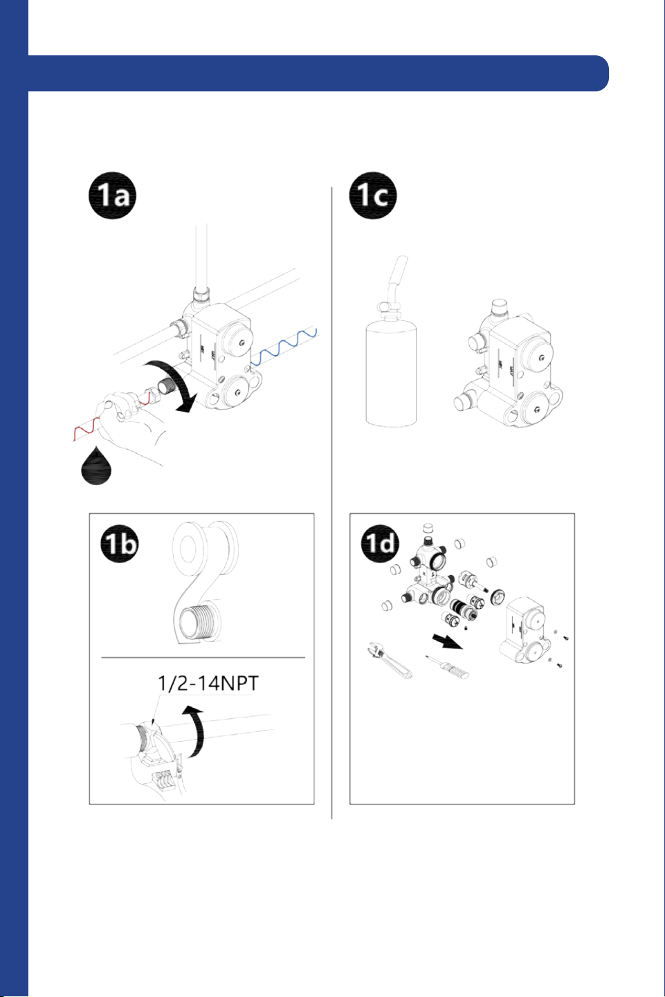
If soldering the water connections when installing the system, remove the O-rings,
cartridges, and washers before applying any heat.
Protect your eyes when cutting or soldering.
Do not over tighten screws/nuts. Finger tighten, then use a wrench/screwdriver to
tighten the fixing screw/nut until snug.
2
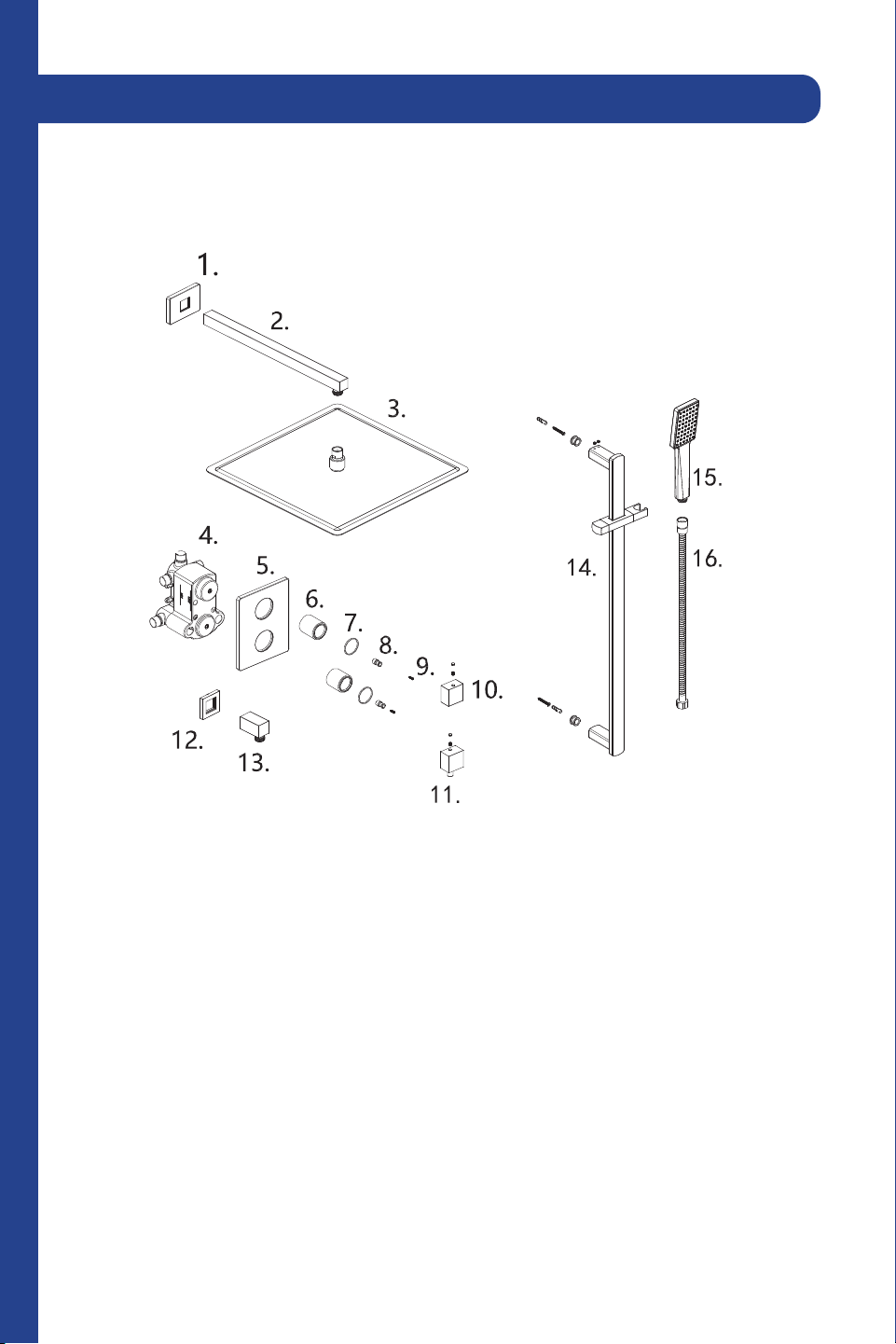
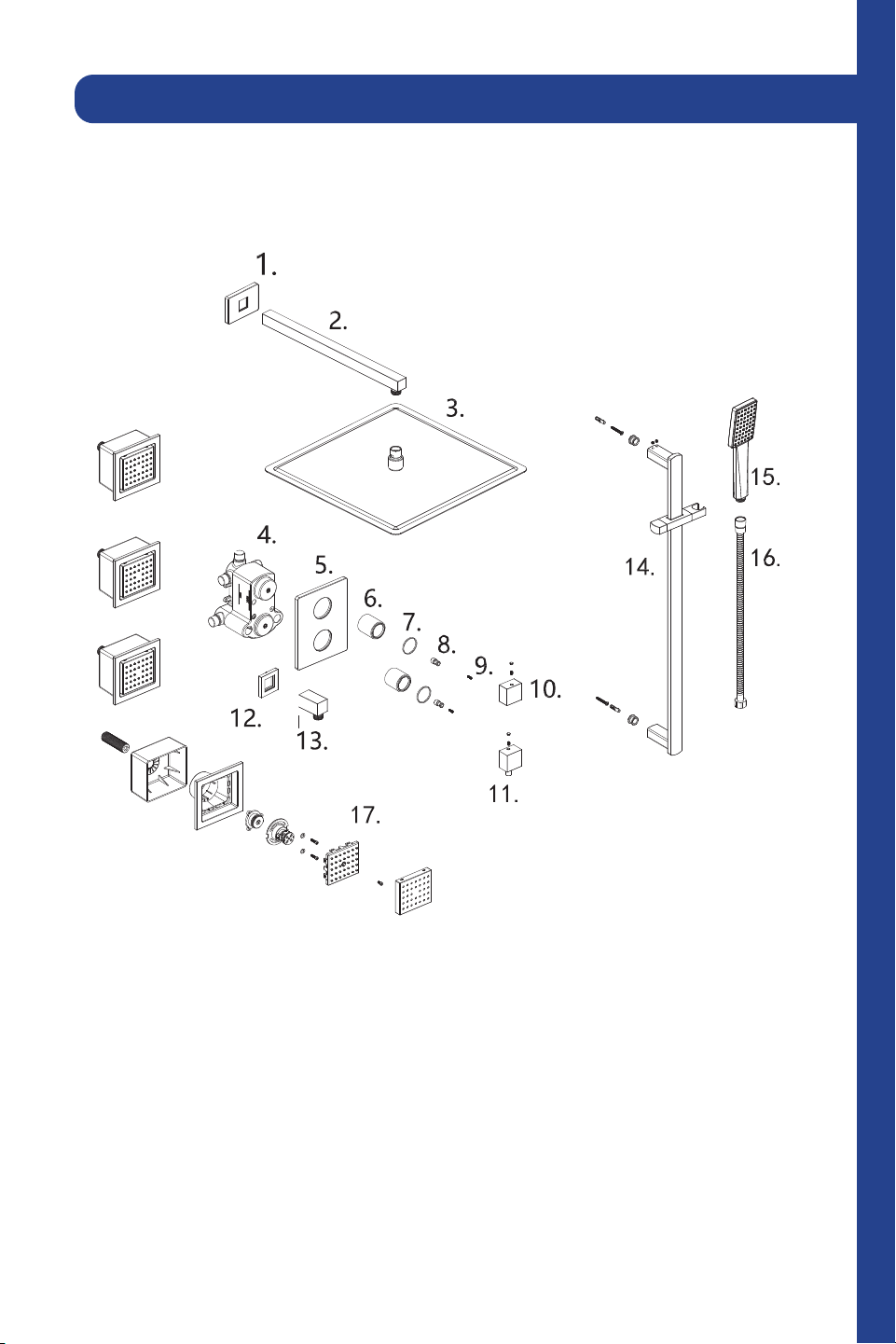
1. Flange cover
2. Shower arm
3. Top spray shower
4. Wall valve body
5. Faceplate
6. Sleeve
7. Washer
8. Tooth
9. Screw
10. Handle
11 . Handle
12 . Flange cover
13. Angle valve
14 . Shower rail
15. Shower handle
16. Hose
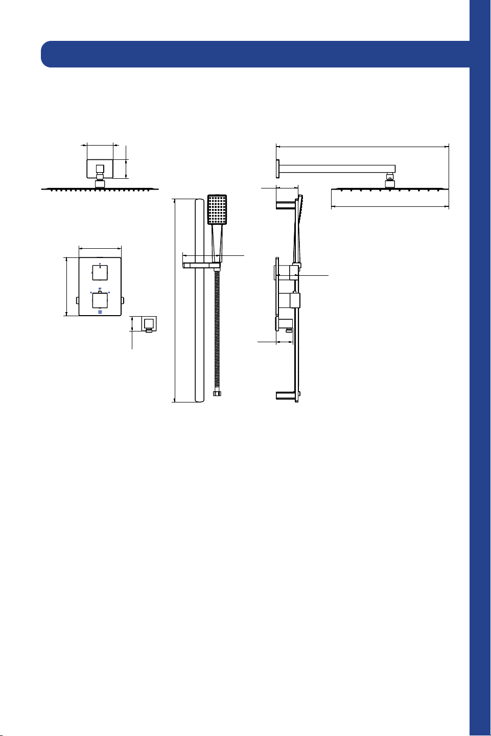
2 Point Shower System (CBY-SHS-T2)
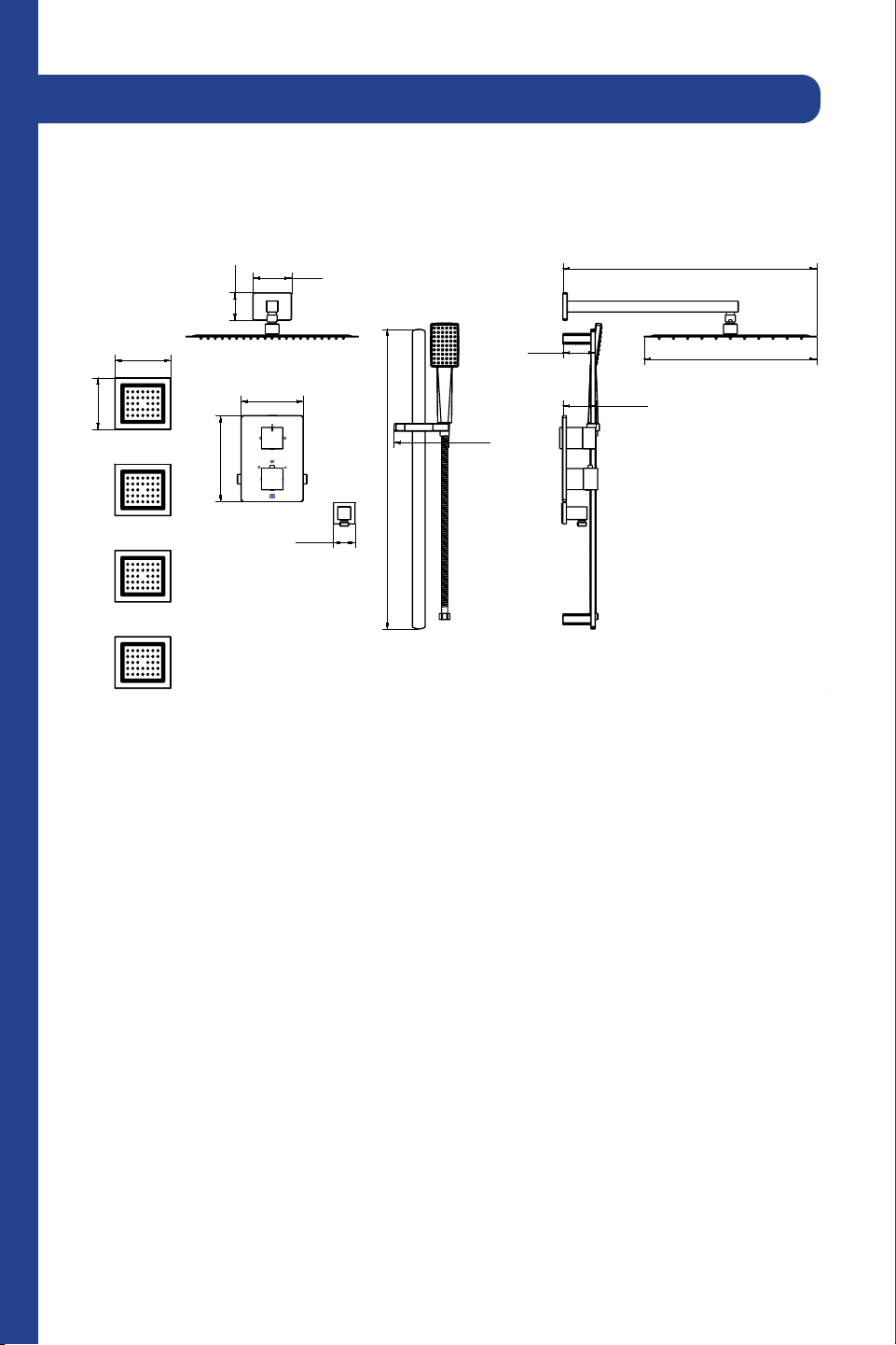
3
PP
,Q
%
PP
,Q
PP
,Q
PP
,Q
,Q
PP
,Q
PP
,Q
%PP
,Q
PP
,Q
0D[PP
0LQ
PP
,Q
PP
,Q
ഃᄍၗ
ۢᅹPPӦส
ಌۢΑ
-XO
-LDQ*DQJᄥ$ұ
ы
γޚ ༉؟ޚৃ ҉ ஆ ఐ
γޚ ༉؟ޚৃ ҉ ஆ ఐ
ۜ ζ҉ ࢺܜۜ ࢺܜ
&& &%<6+67&+
ֺۺัܰঅ၄
2 Point Shower System (CBY-SHS-T2)
4
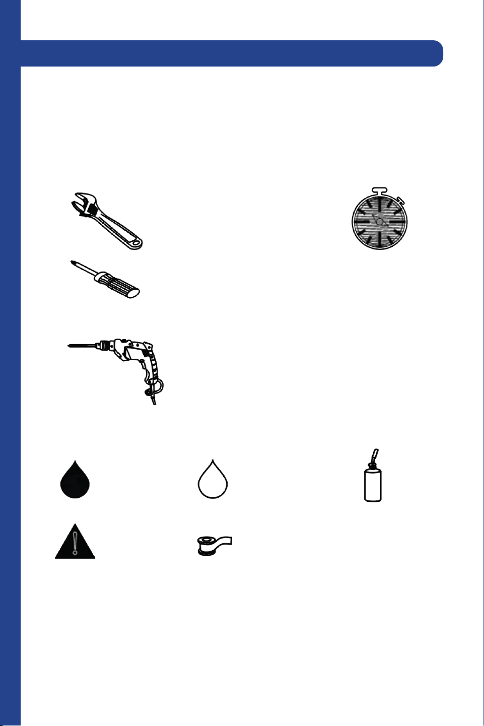
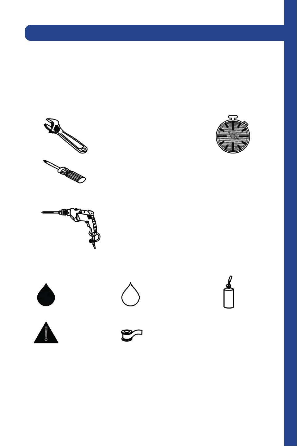
Tools:
Time required:
+/- 120 minutes
Wrench
Legend:
Hot Water
Warning
Cold Water
Plumber’s Tape
Torch
Screwdriver
Drill
2 Point Shower System (CBY-SHS-T2)
5
Time required:
+/- 120 minutes
Torch
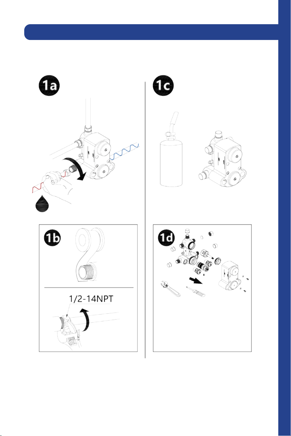
Slide the sleeves onto the pipes and then insert pipes into the wall valve.
Tighten the ring around the pipes with the wrench.
2 Point Shower System (CBY-SHS-T2)
6
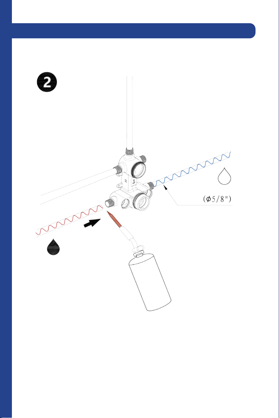
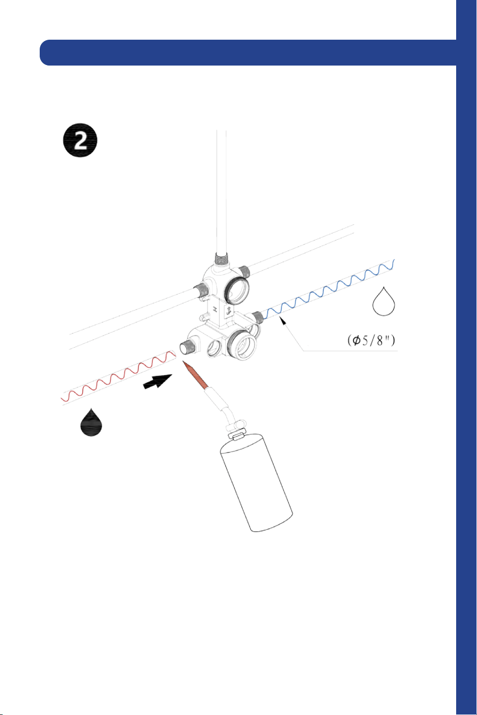
Weld the copper together or use plumber’s tape to prevent leaks.
2 Point Shower System (CBY-SHS-T2)
7
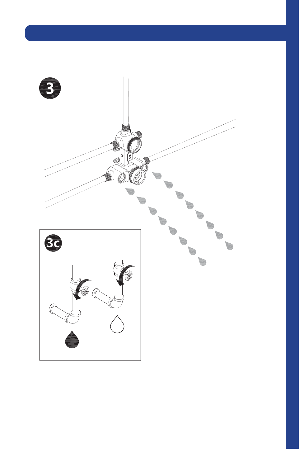
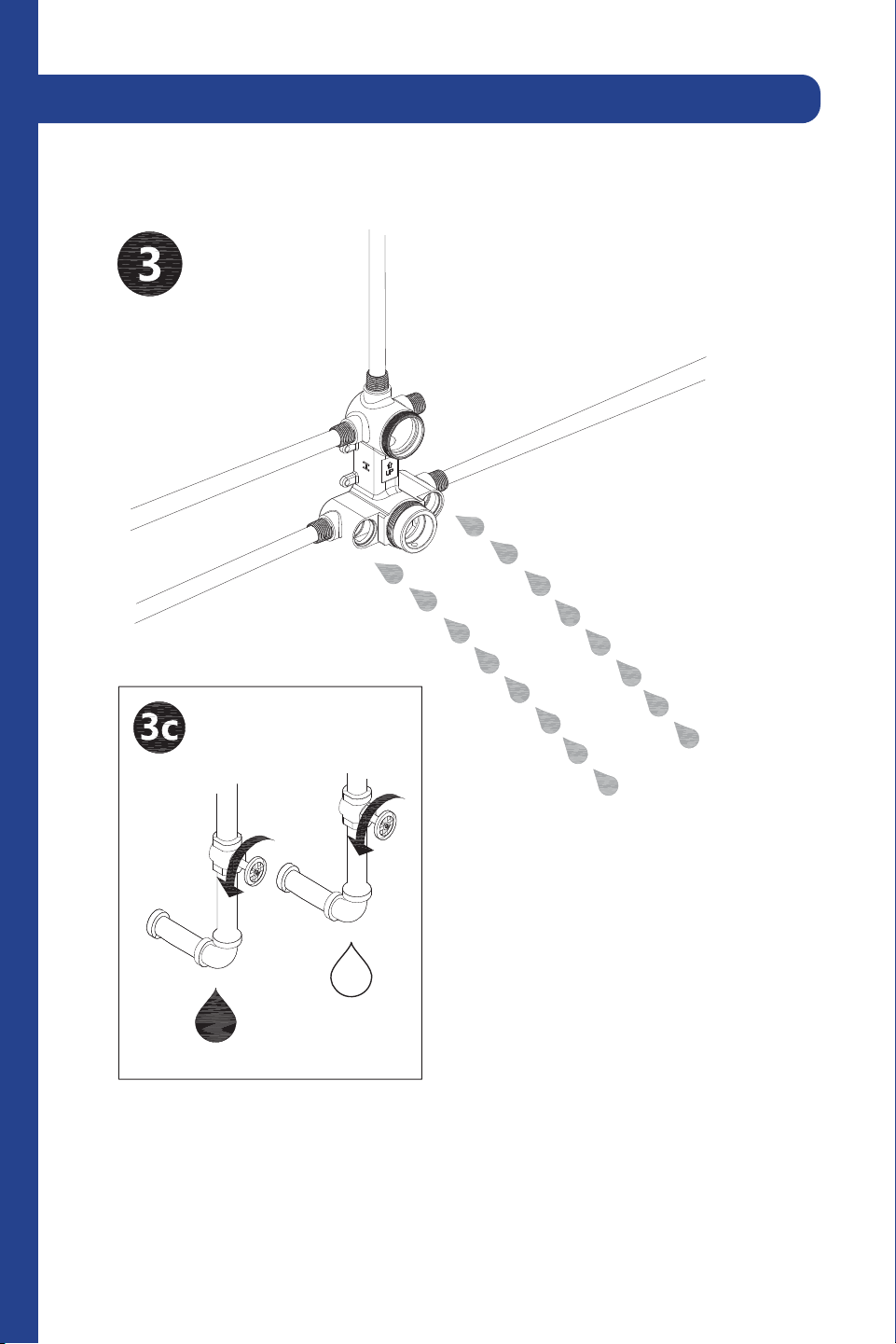
After welding, purge the water supply system for 30 seconds.
2 Point Shower System (CBY-SHS-T2)
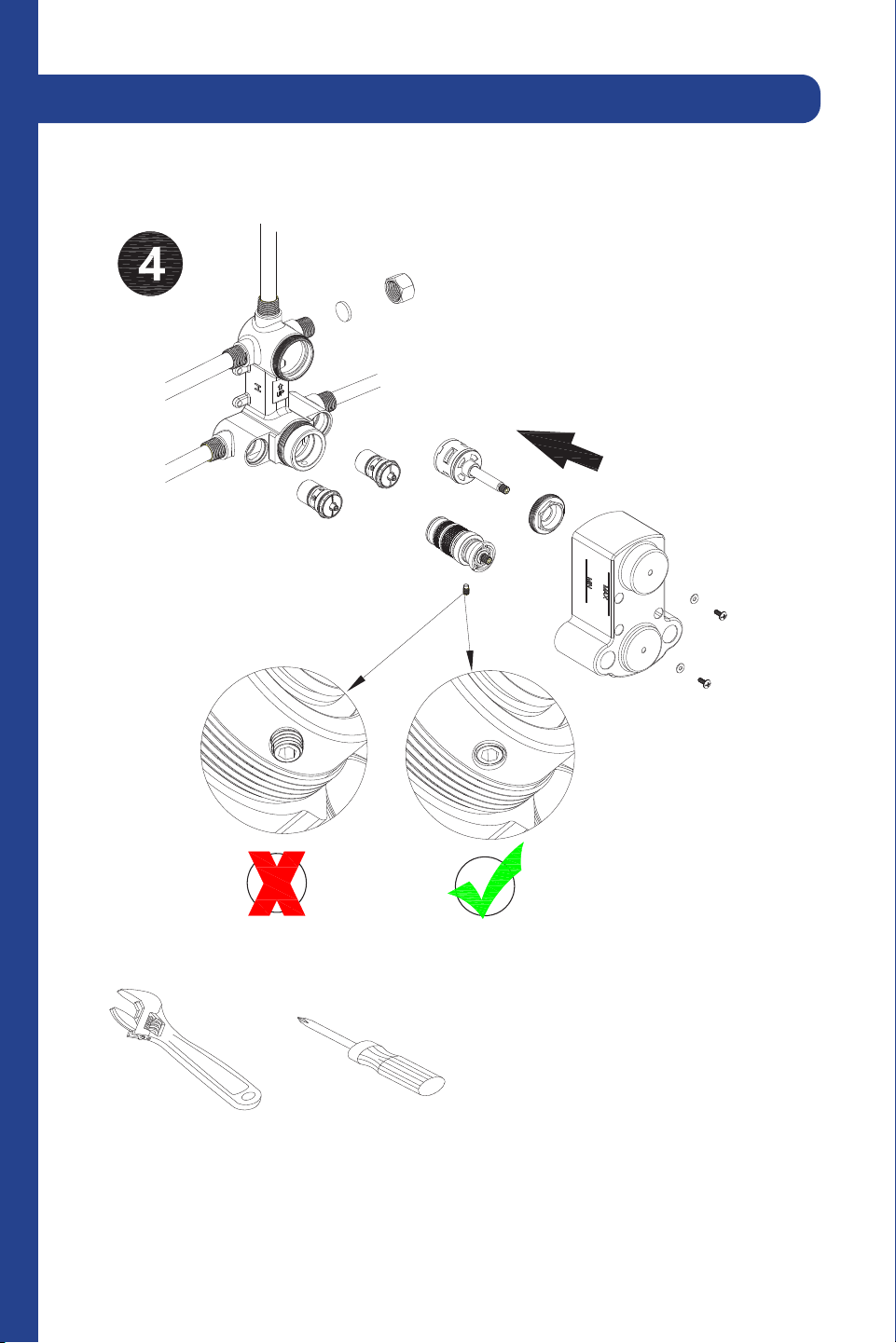
8
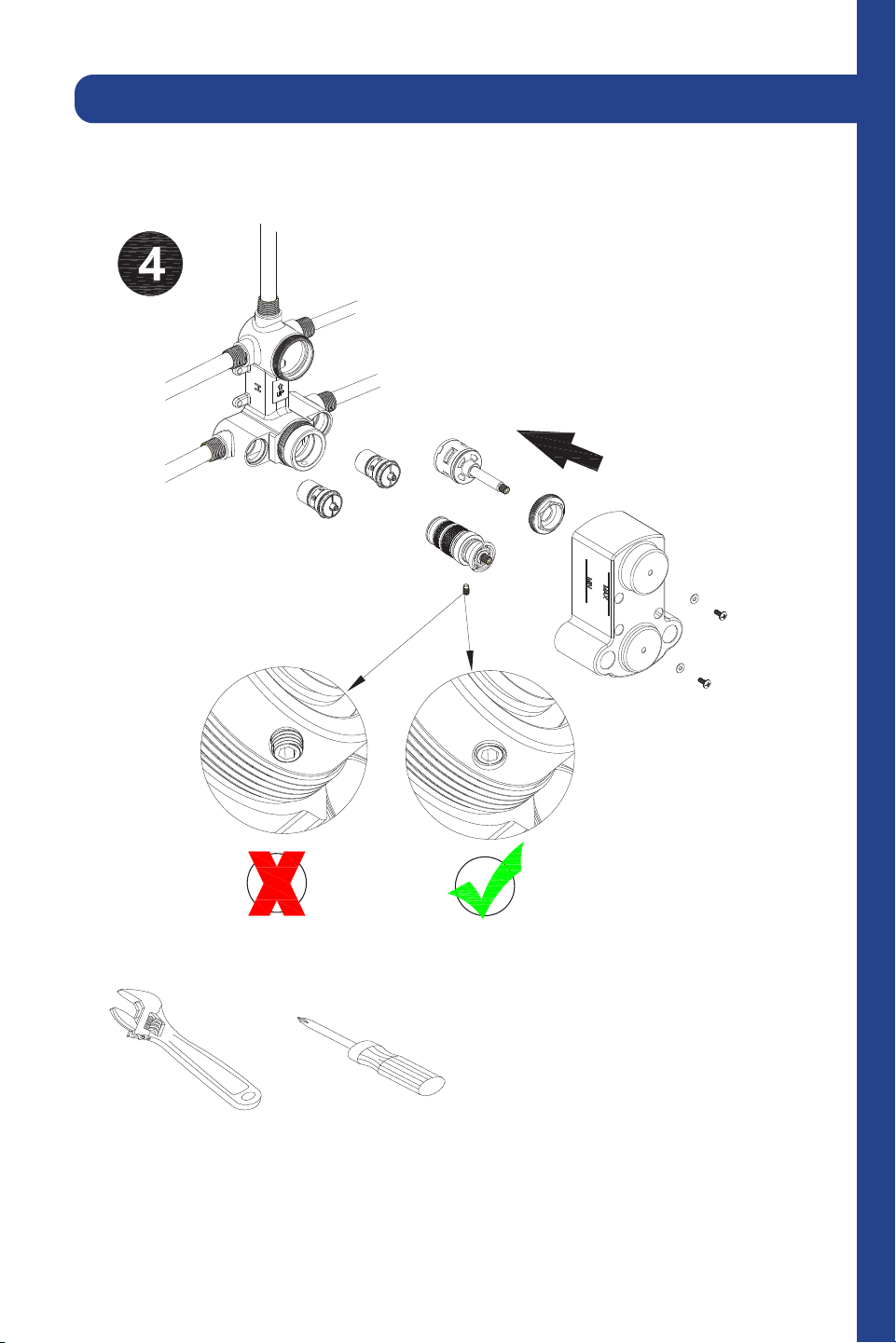
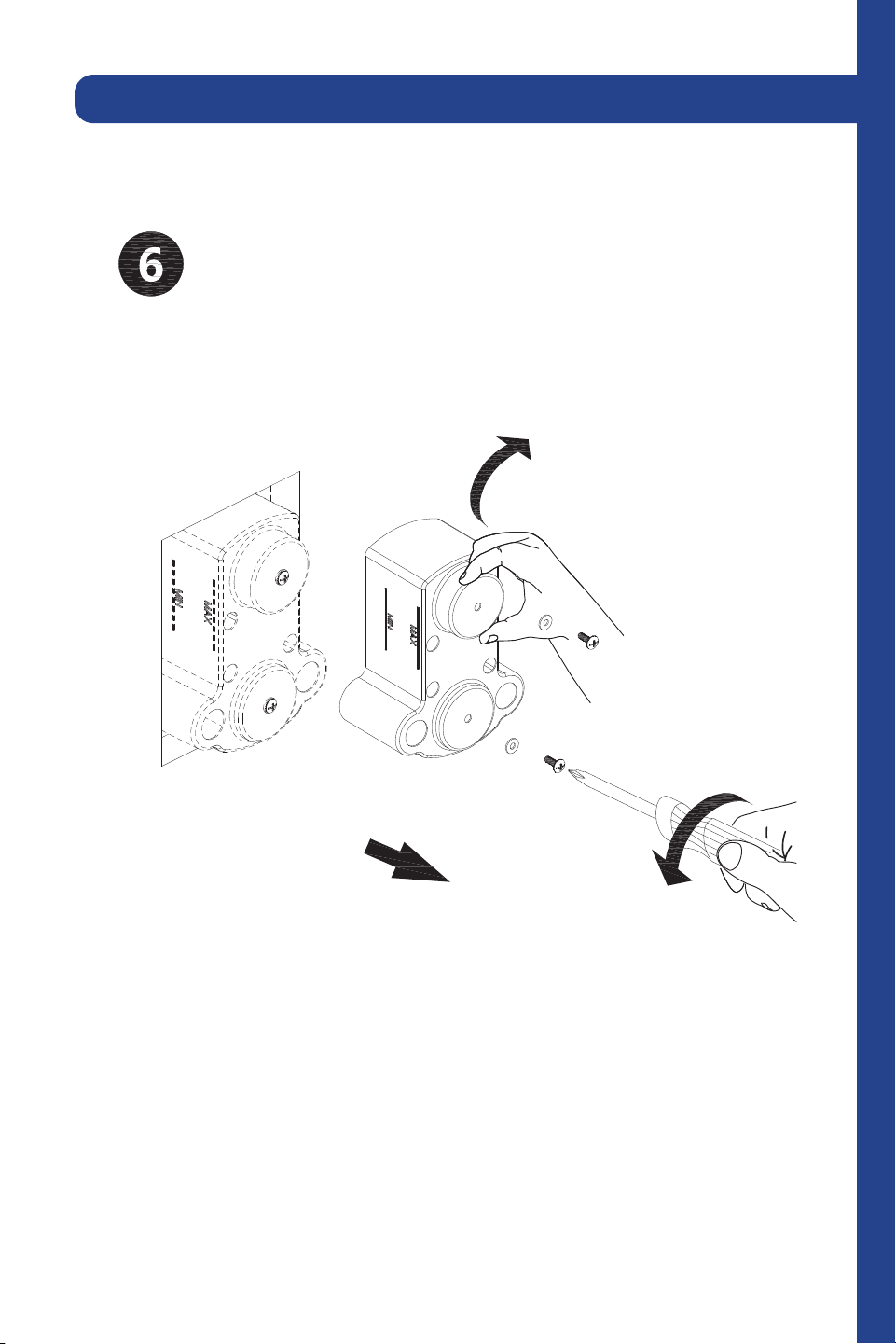
Reinstall the valve components into their original positions.
2 Point Shower System (CBY-SHS-T2)
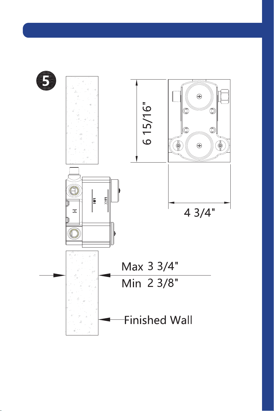
9
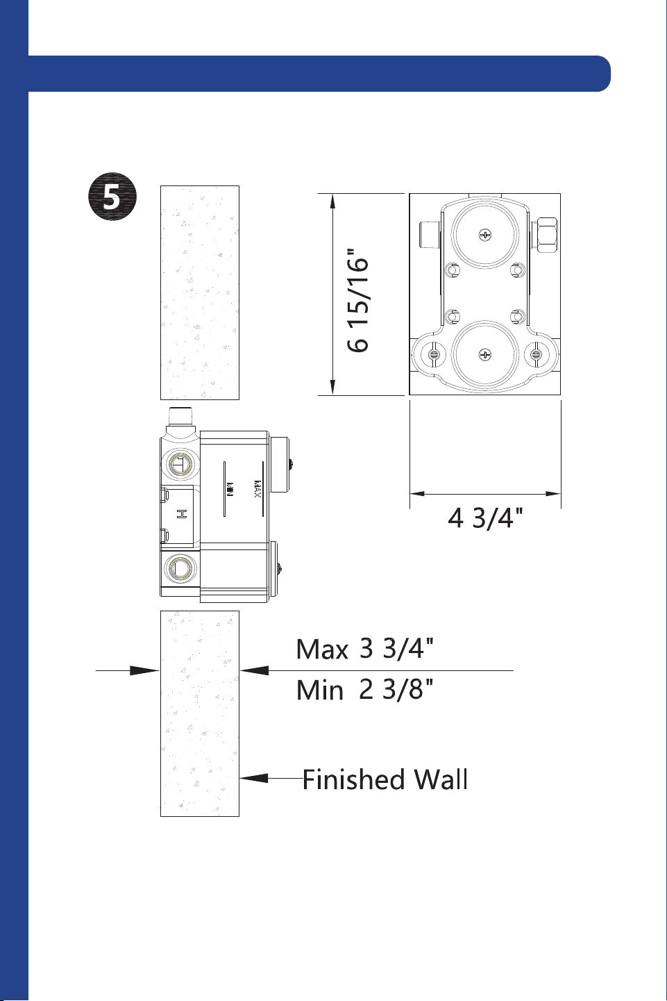
Use this diagram to understand the placement of the wall valve.
2 Point Shower System (CBY-SHS-T2)
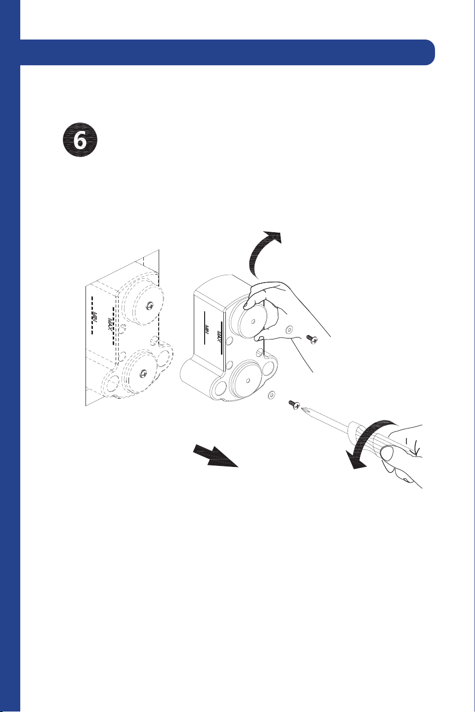
10
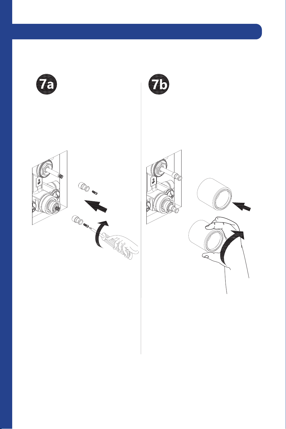
Screw the wall valve body into the system with a screwdriver. Do not
overtighten.
2 Point Shower System (CBY-SHS-T2)
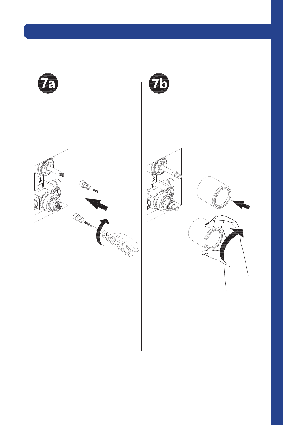
11
Screw the sleeve and washer into the wall valve body.
2 Point Shower System (CBY-SHS-T2)
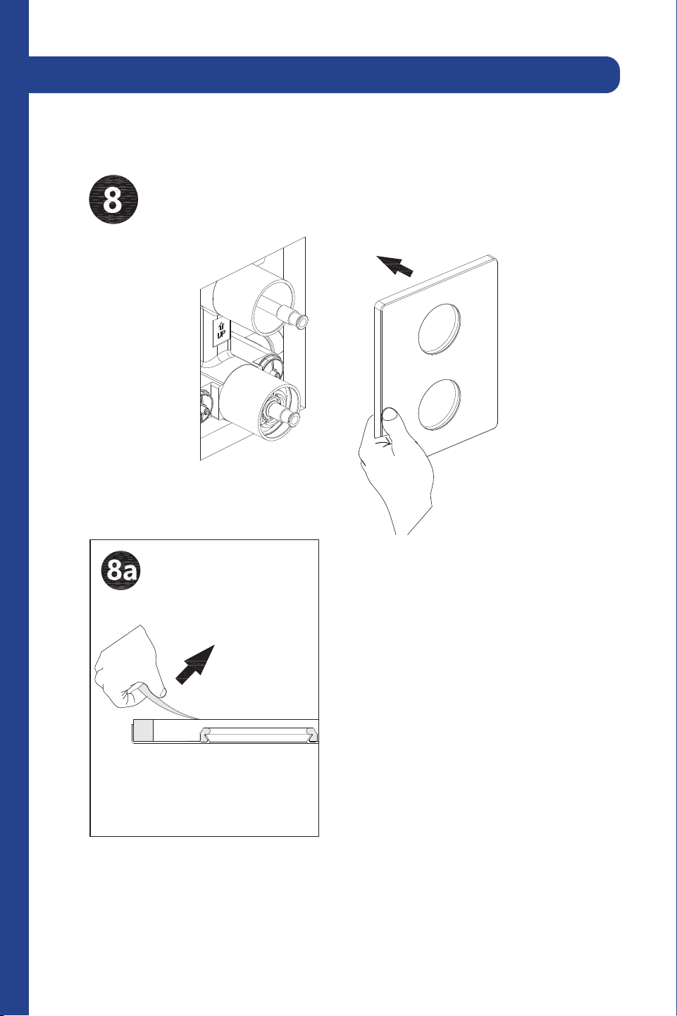
12
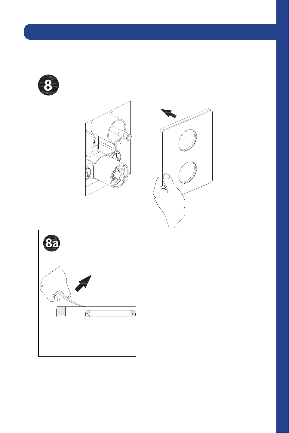
Attach the faceplate and remove the plastic.
2 Point Shower System (CBY-SHS-T2)
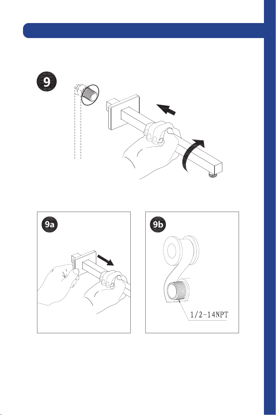
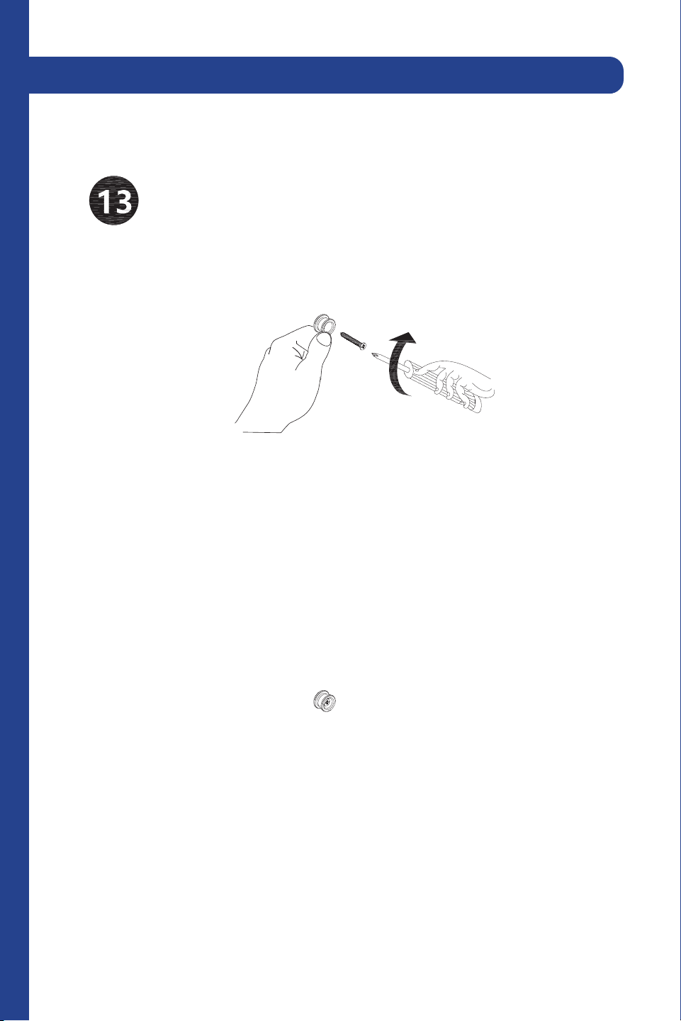
13
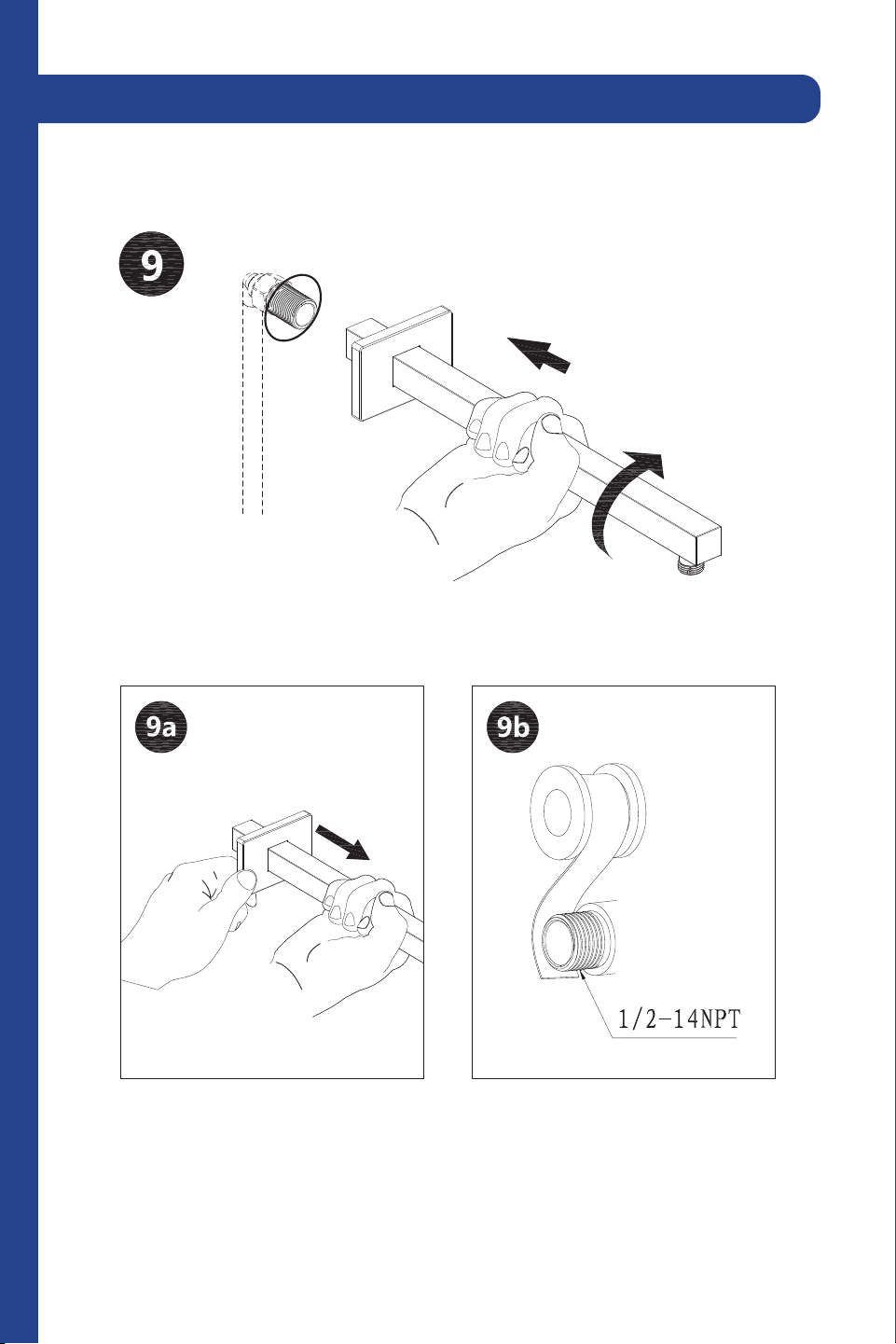
Connect the flange cover to the spout in the wall. Secure with plumber’s
tape to prevent leaks.
2 Point Shower System (CBY-SHS-T2)
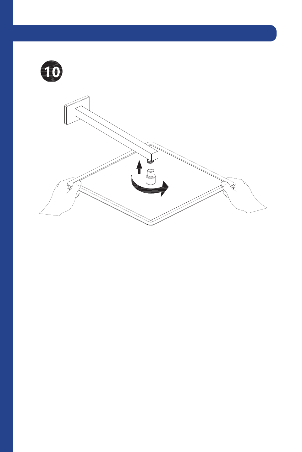
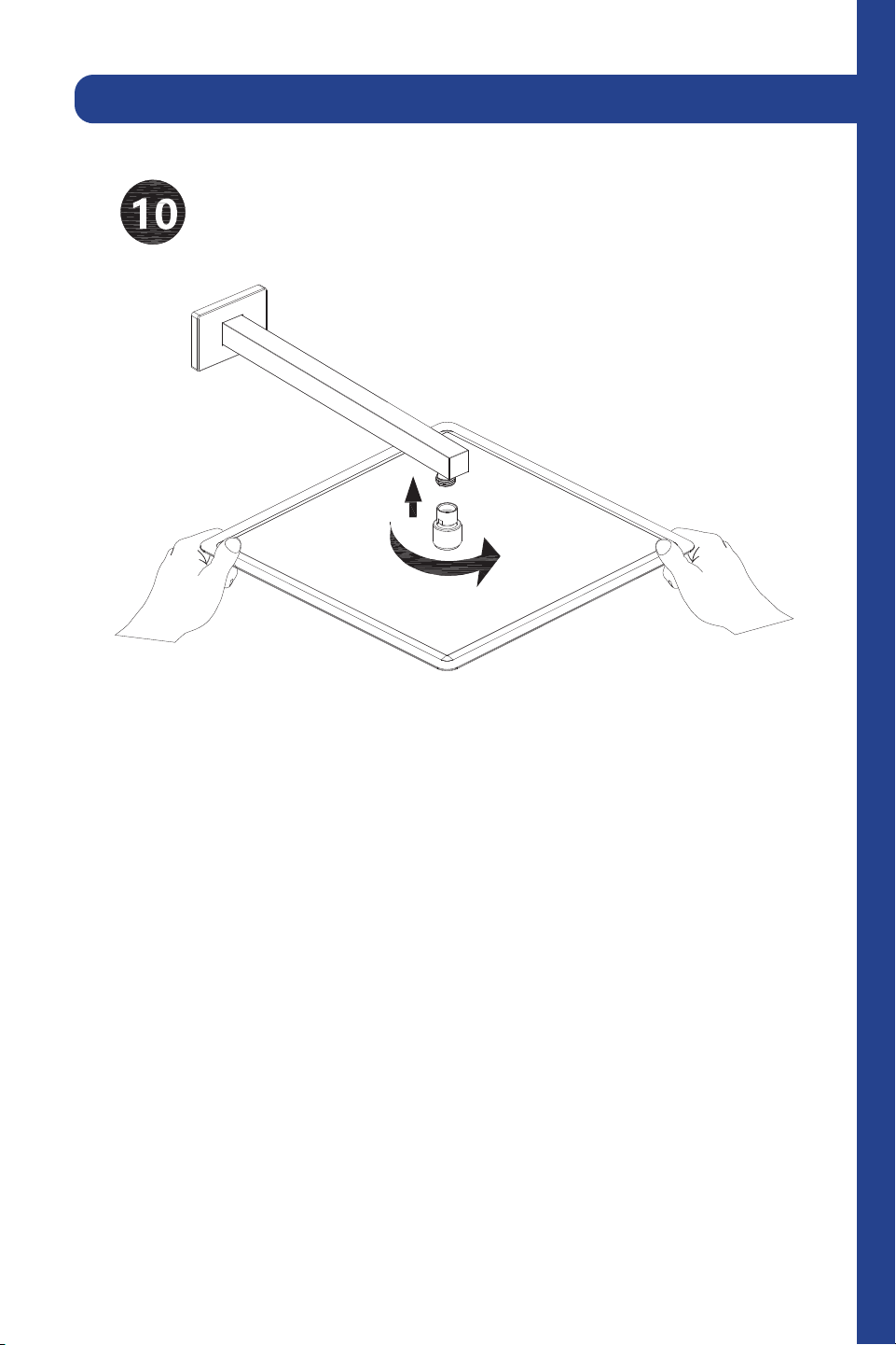
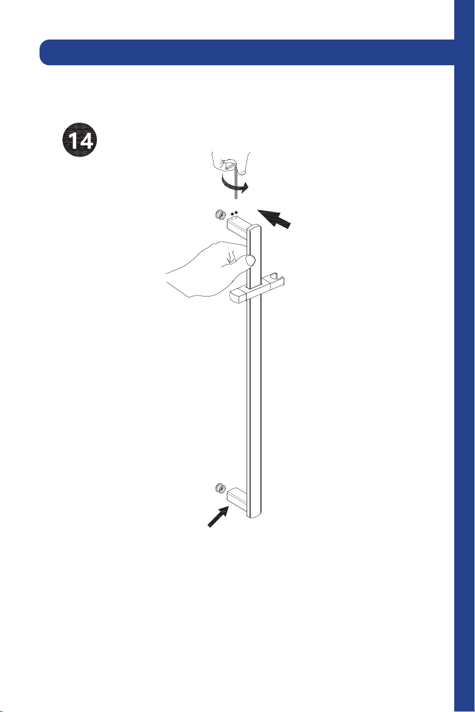
14
Twist the top spray shower into the shower arm.
2 Point Shower System (CBY-SHS-T2)
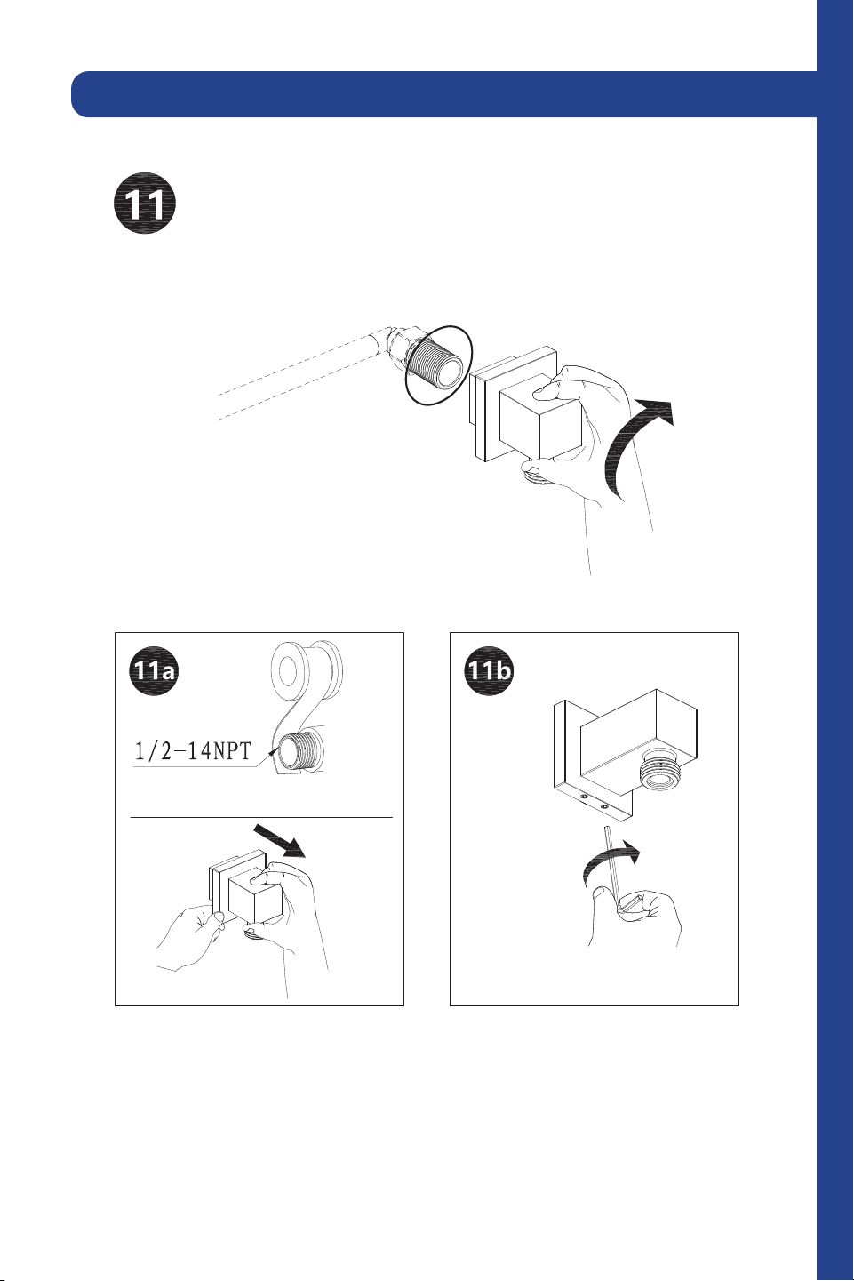
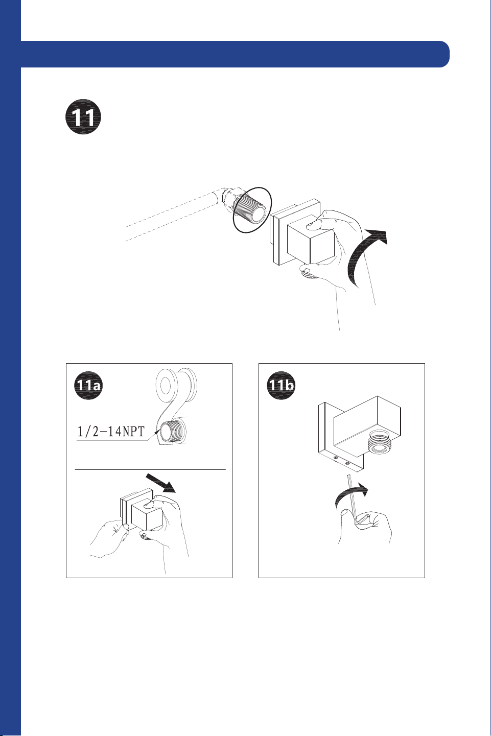
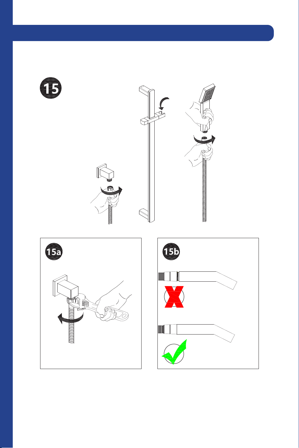
15
Connect the angle valve to the flange cover and screw together. Secure
with plumber’s tape to prevent leaks.
2 Point Shower System (CBY-SHS-T2)
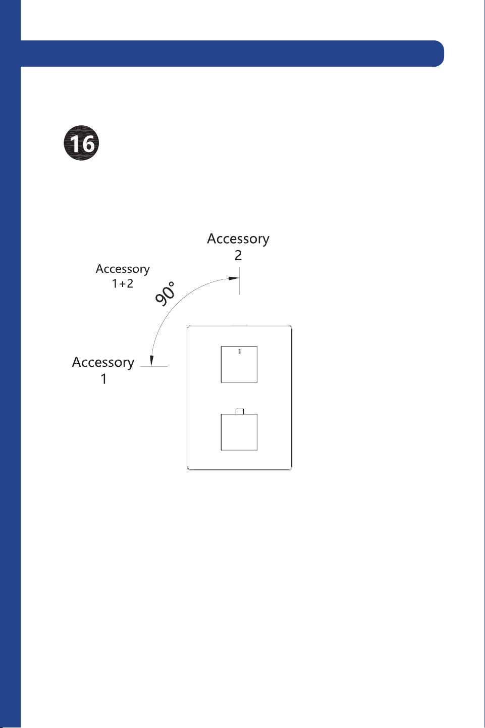
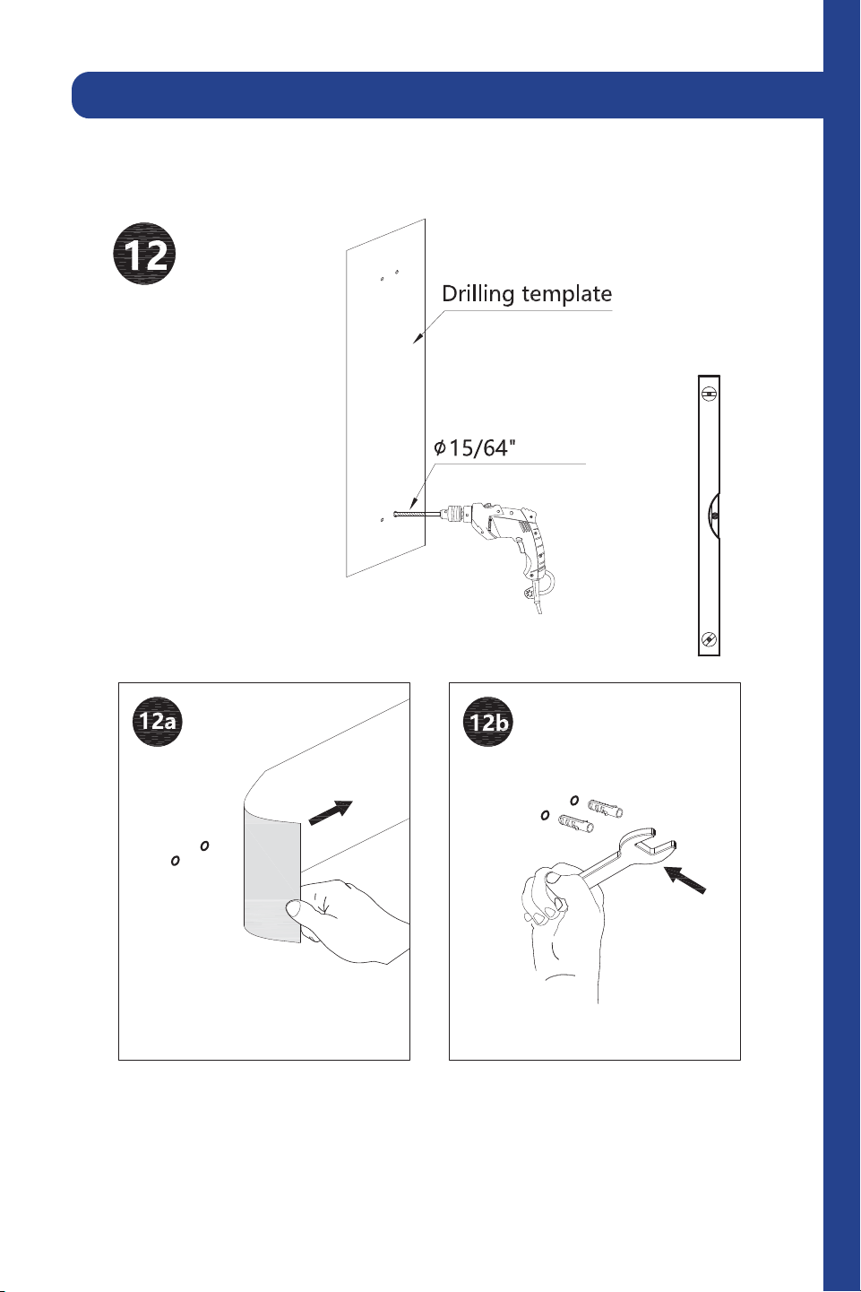
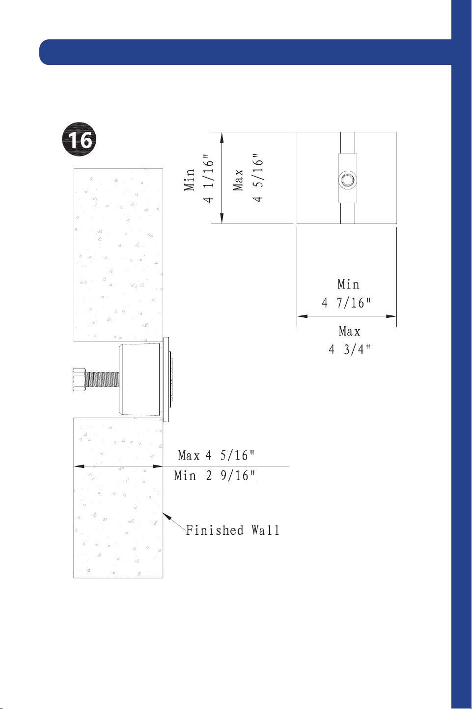
16
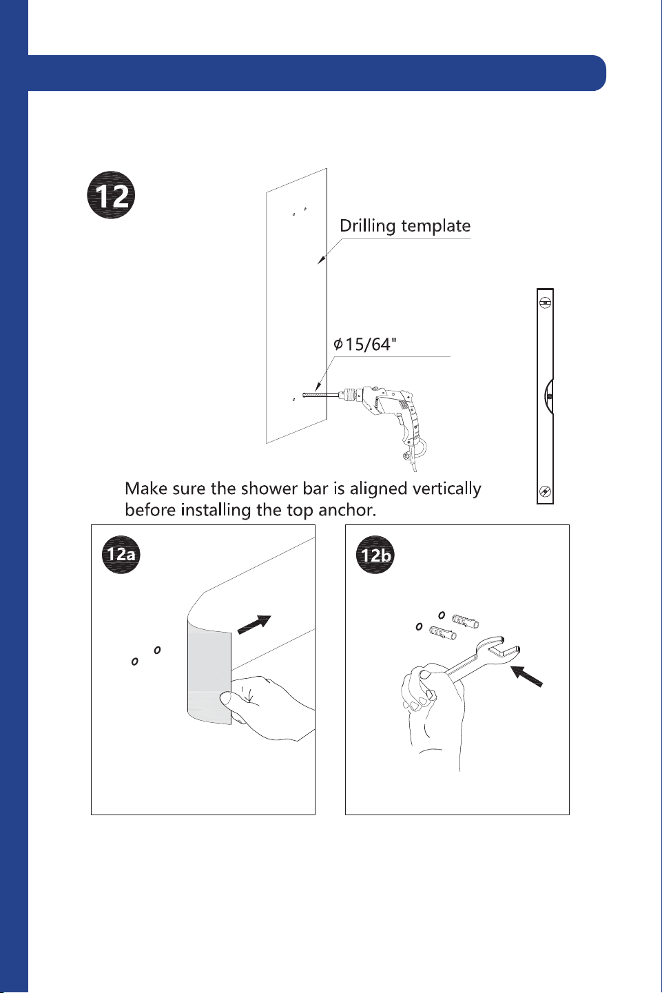
Make sure the shower bar is aligned vertically before installing the top
anchor.
2 Point Shower System (CBY-SHS-T2)
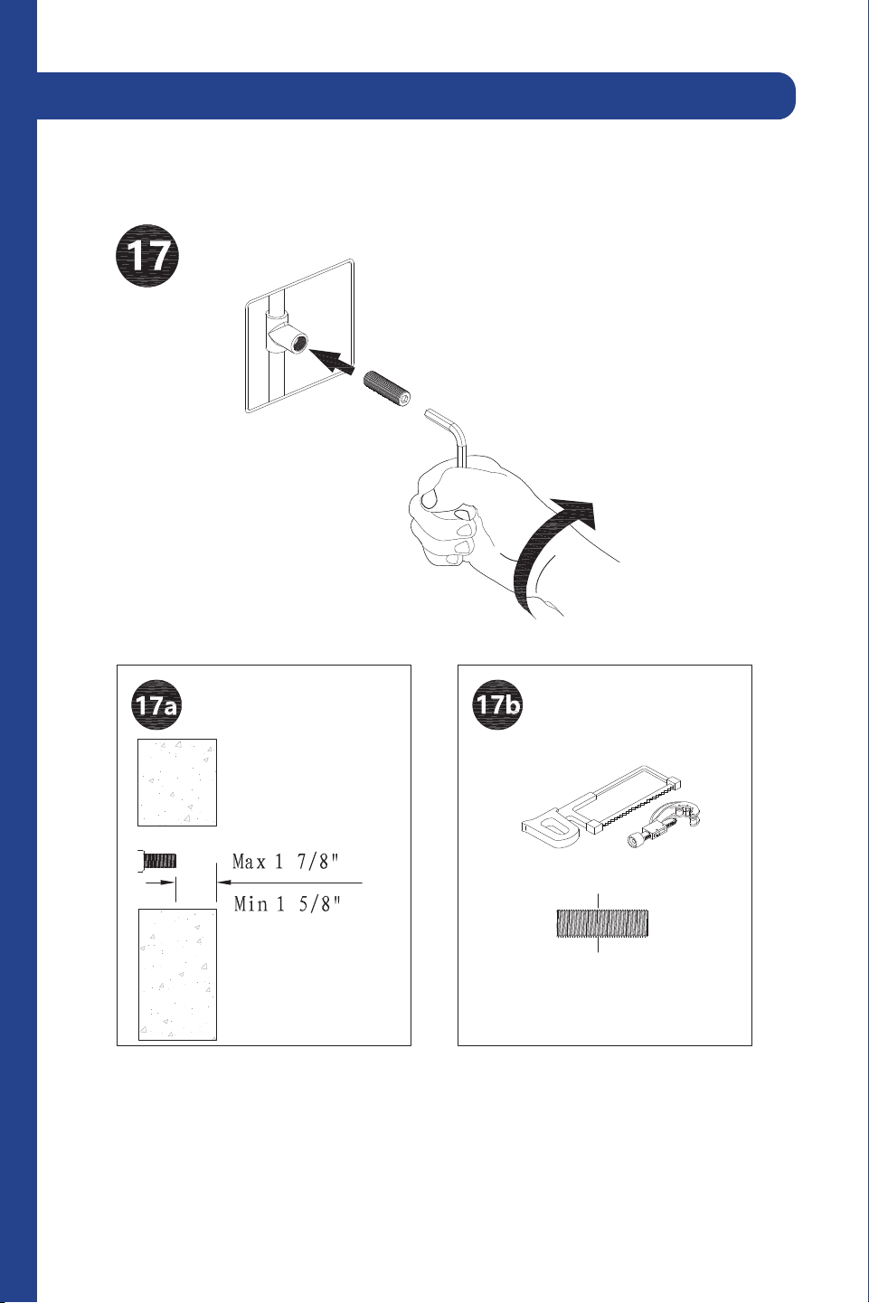
17
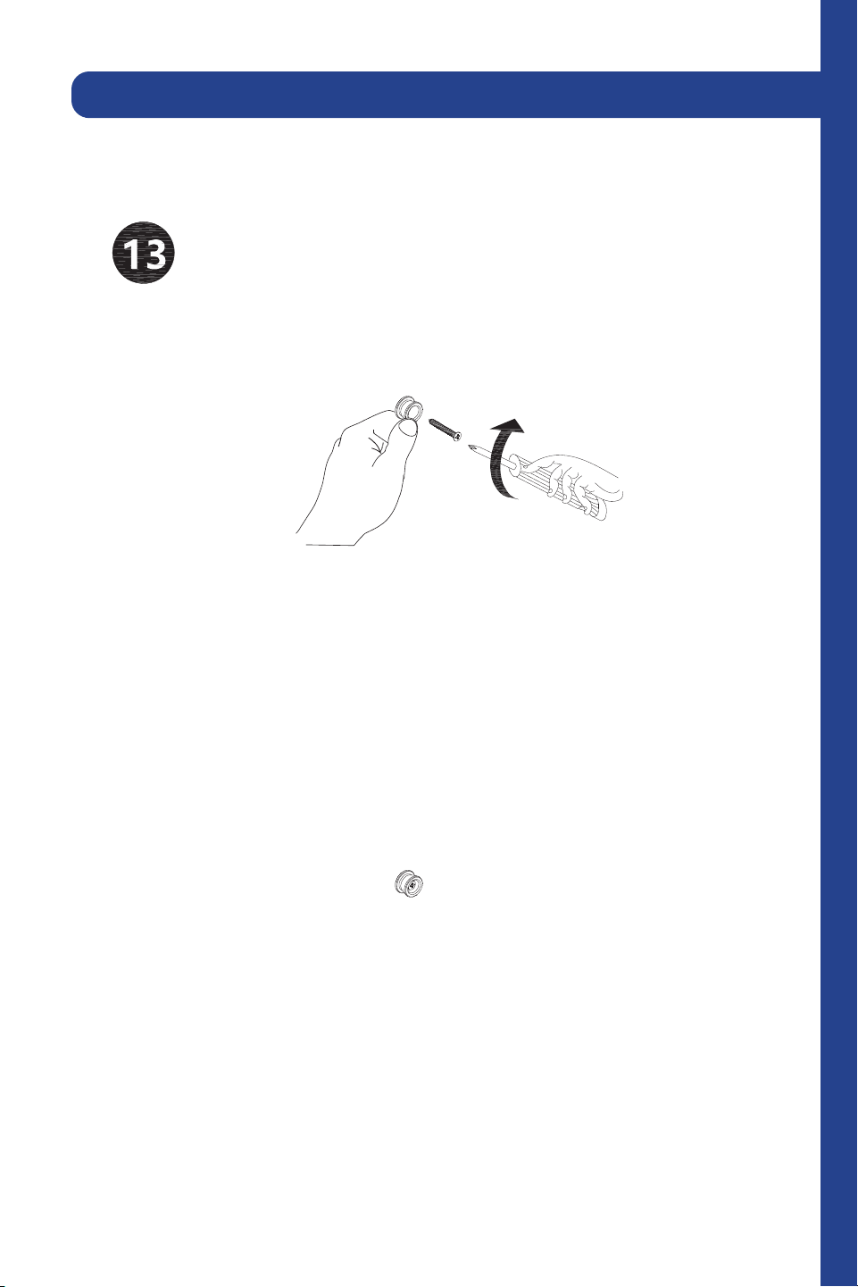
Secure the mounting brackets into place.
2 Point Shower System (CBY-SHS-T2)
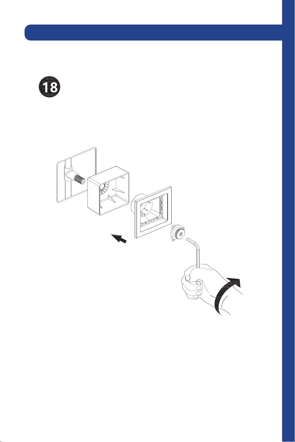
18
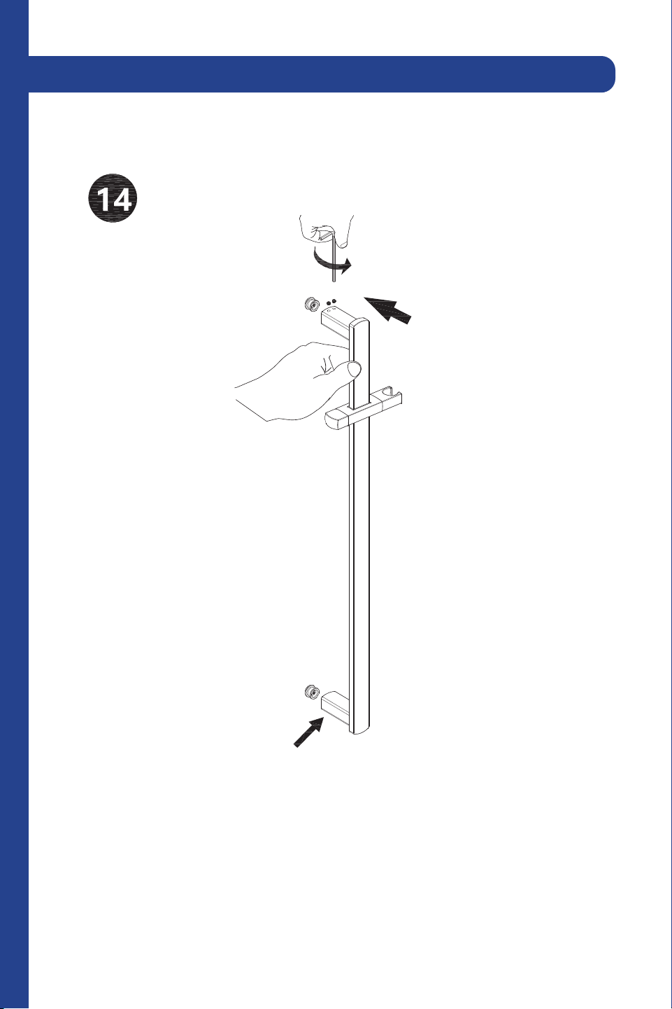
Connect the components of the shower rail.
2 Point Shower System (CBY-SHS-T2)
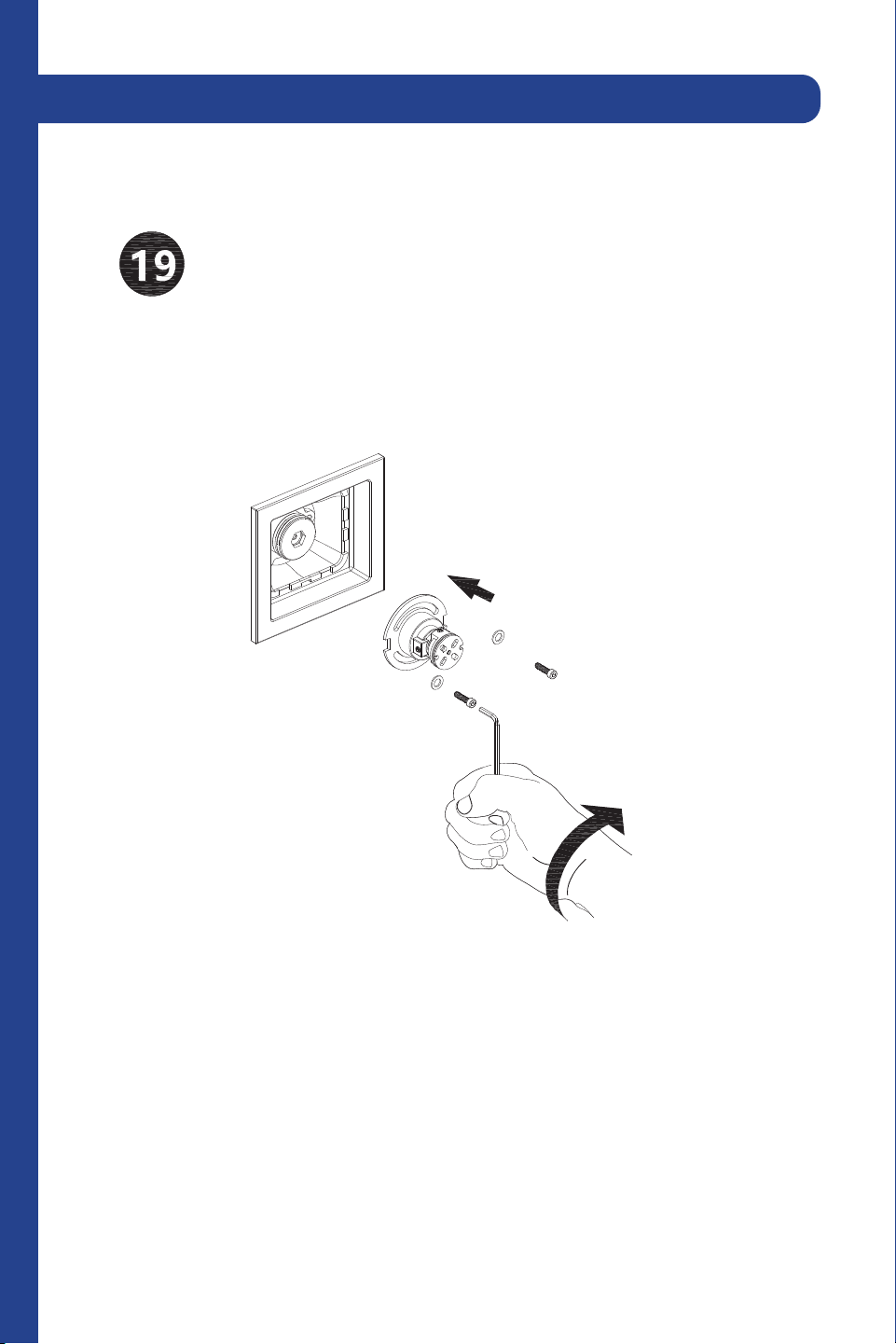
19
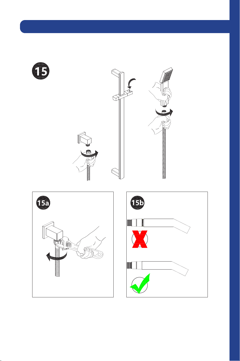
Connect the shower handle to the shower rail. Tighten with a wrench.
2 Point Shower System (CBY-SHS-T2)
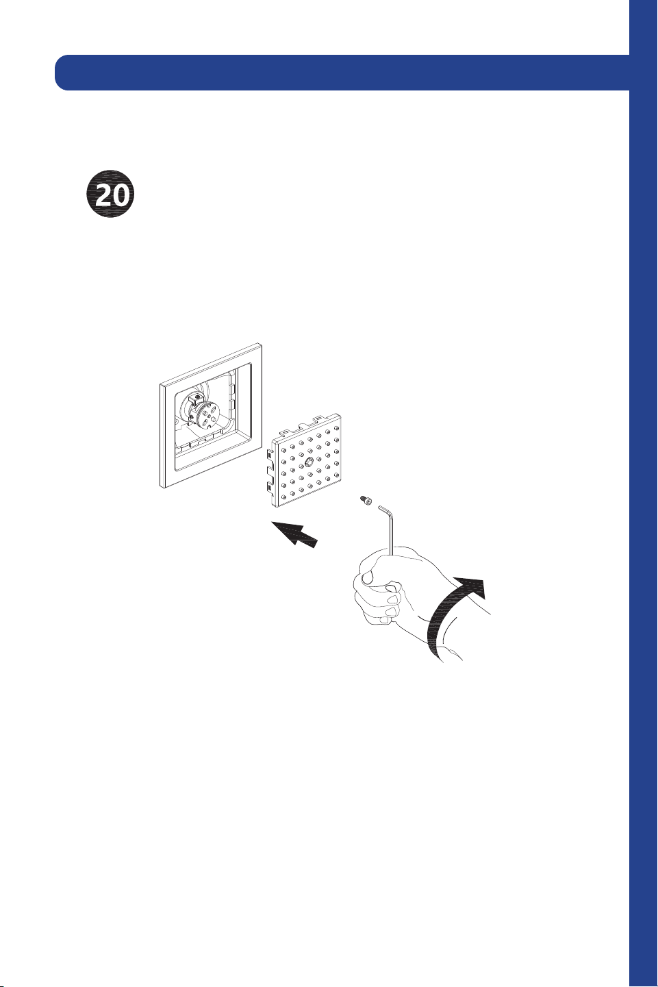
20
Review the diagram to understand the hot, cold, and open settings.
2 Point Shower System (CBY-SHS-T2)
21
1. Flange cover
2. Shower arm
3. Top spray shower
4. Wall valve body
5. Faceplate
6. Sleeve
7. Washer
8. Tooth
9. Screw
10. Handle
11 . Handle
12 . Flange cover
13. Angle valve
14 . Shower rail
15. Shower handle
16. Hose
17. Built-in body jet
3 Point Shower System (CBY-SHS-T3
22
PP
,Q
PP
,Q
PP
,Q
0D[PP
0LQPP
PP
,Q
PP
,Q
%PP
,Q
PP
,Q
PP
,Q
PP
,Q
PP
,Q
PP
,Q
PP
,Q
ഃᄍၗ
ۢᅹPPӦส
ಌۢΑ
-XO
-LDQ*DQJᄥ$ұ
ы
γޚ ༉؟ޚৃ ҉ ஆ ఐ
γޚ ༉؟ޚৃ ҉ ஆ ఐ
ۜ ζ҉ ࢺܜۜ ࢺܜ
&& &%<6+67&+
ֺۺัܰঅ၄
3 Point Shower System (CBY-SHS-T3
23
Tools:
Time required:
+/- 120 minutes
Wrench
Legend:
Hot Water
Warning
Cold Water
Plumber’s Tape
Torch
Screwdriver
Drill
3 Point Shower System (CBY-SHS-T3
24
Slide the sleeves onto the pipes and then insert pipes into the wall valve.
Tighten the ring around the pipes with the wrench.
3 Point Shower System (CBY-SHS-T3
25
Weld the copper together or use plumber’s tape to prevent leaks.
3 Point Shower System (CBY-SHS-T3
26
After welding, purge the water supply system for 30 seconds.
3 Point Shower System (CBY-SHS-T3
27
Reinstall the valve components into their original positions.
3 Point Shower System (CBY-SHS-T3
28
Use this diagram to understand the placement of the wall valve.
3 Point Shower System (CBY-SHS-T3
29
Screw the wall valve body into the system with a screwdriver. Do not
overtighten.
3 Point Shower System (CBY-SHS-T3
30
Screw the sleeve and washer into the wall valve body.
3 Point Shower System (CBY-SHS-T3
31
Attach the faceplate and remove the plastic.
3 Point Shower System (CBY-SHS-T3
32
Connect the flange cover to the spout in the wall. Secure with plumber’s
tape to prevent leaks.
3 Point Shower System (CBY-SHS-T3
33
Twist the top spray shower into the shower arm.
3 Point Shower System (CBY-SHS-T3
34
Connect the angle valve to the flange cover and screw together. Secure
with plumber’s tape to prevent leaks.
3 Point Shower System (CBY-SHS-T3
35
Make sure the shower bar is aligned vertically before installing the top
anchor.
3 Point Shower System (CBY-SHS-T3
36
Secure the mounting brackets into place.
3 Point Shower System (CBY-SHS-T3
37
Connect the components of the shower rail.
3 Point Shower System (CBY-SHS-T3
38
Connect the shower handle to the shower rail. Tighten with a wrench.
3 Point Shower System (CBY-SHS-T3
39
Use this diagram to understand the placement of the body jet.
3 Point Shower System (CBY-SHS-T3
40
Secure the body jet base with the hex key.
3 Point Shower System (CBY-SHS-T3
41
Use this diagram to understand how the body jet components to
understand how they fit together.
3 Point Shower System (CBY-SHS-T3
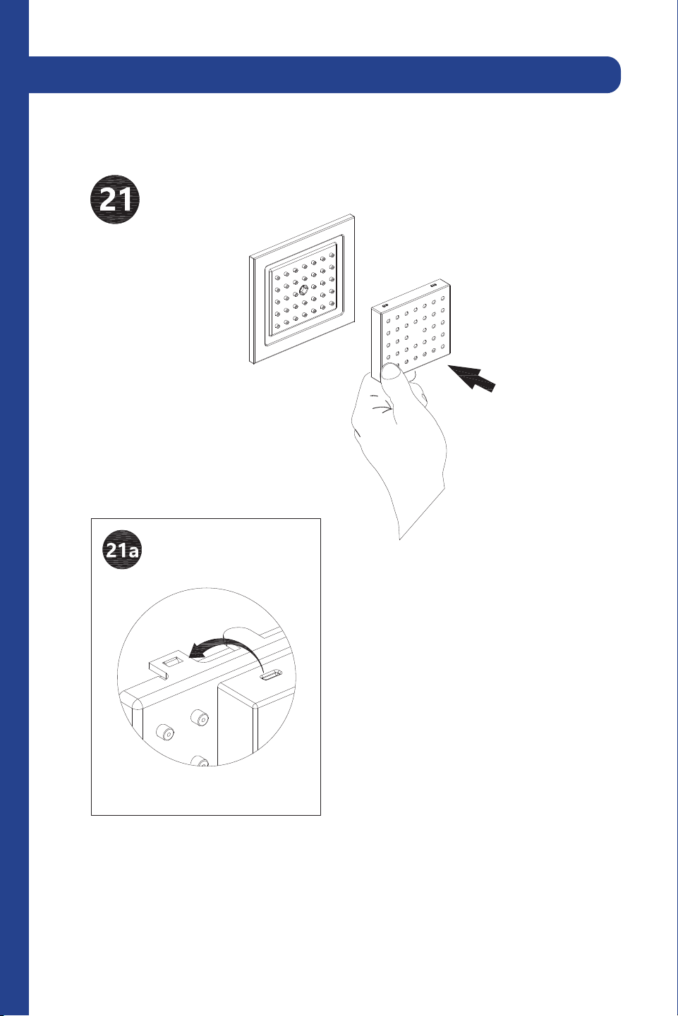
42
Secure the body jet components into place with the set screws.
3 Point Shower System (CBY-SHS-T3
43
Secure the front plate with the set screw.
3 Point Shower System (CBY-SHS-T3
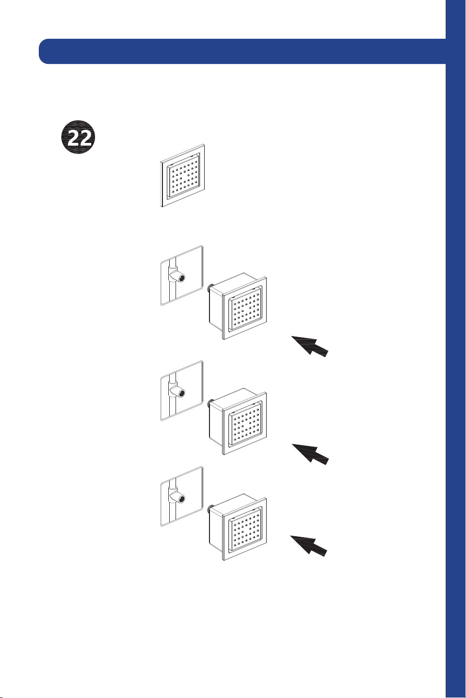
44
Snap the front of the body jet into place.
3 Point Shower System (CBY-SHS-T3
45
Repeat for each body jet.
3 Point Shower System (CBY-SHS-T3
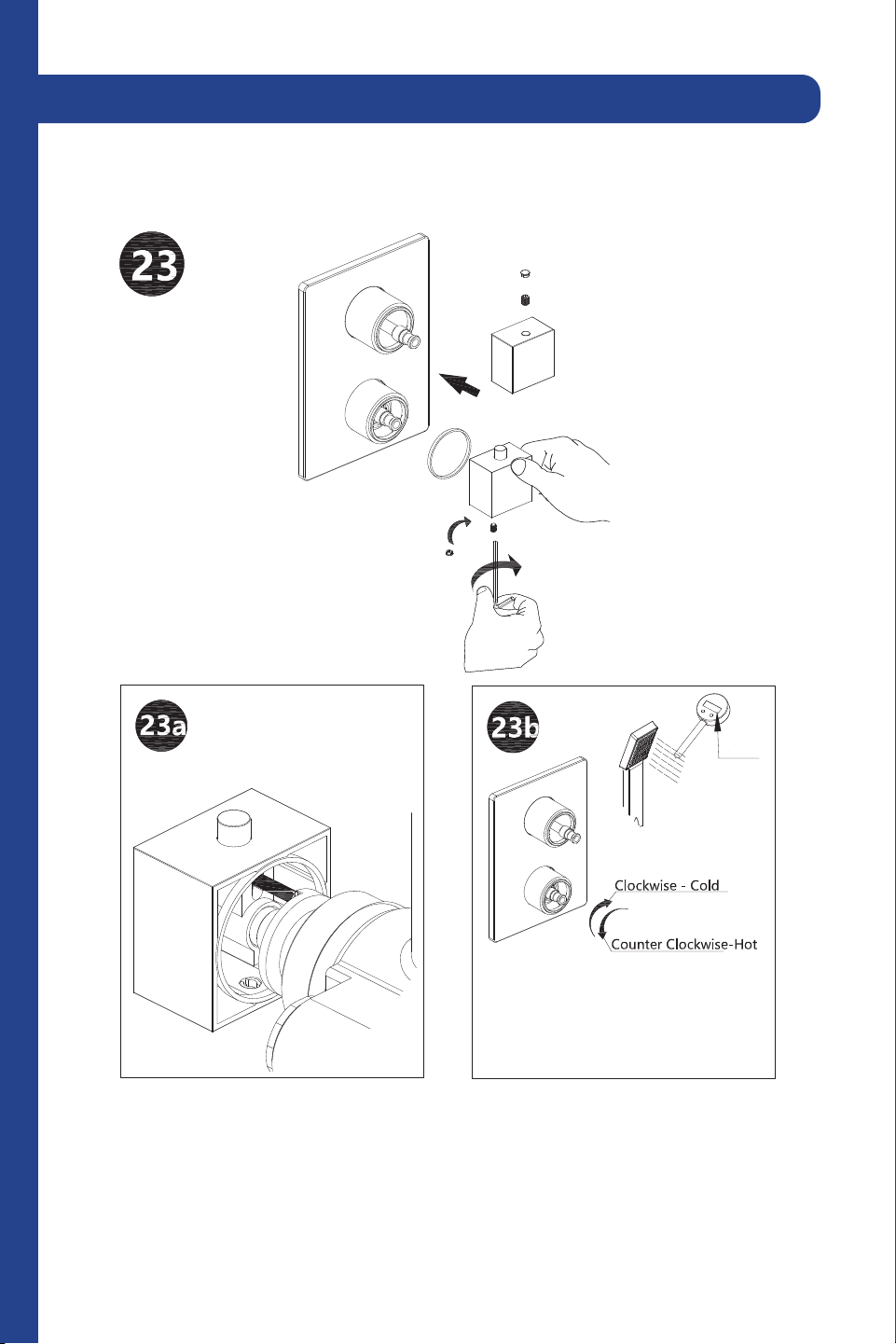
46
Use a thermometer to calibrate the cartridge. Make sure the water
temperature is 100.4°F.
100.4°F
100.4°F
3 Point Shower System (CBY-SHS-T3
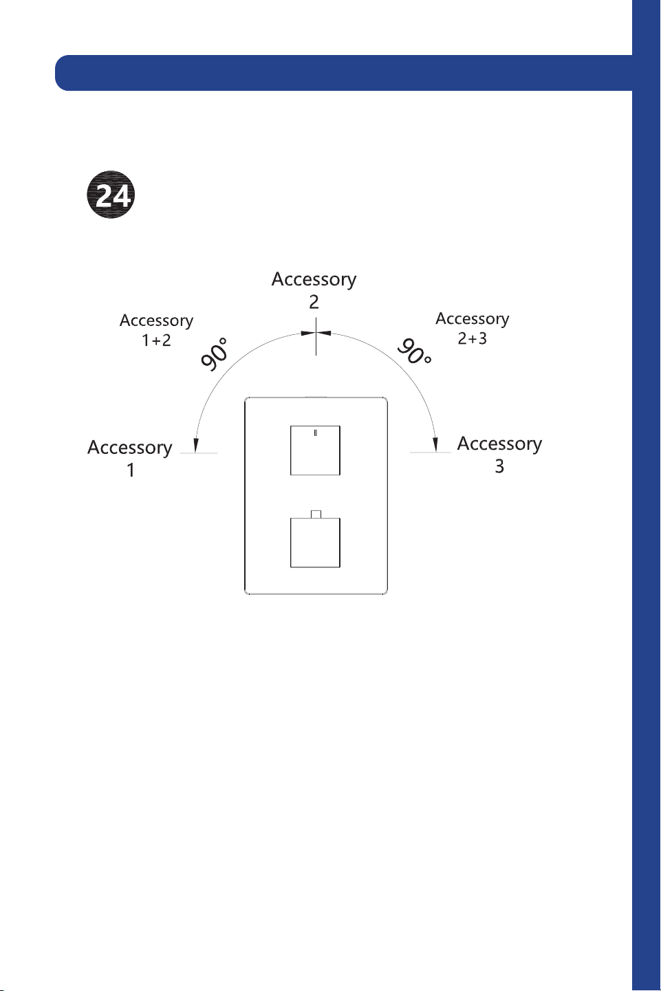
47
Review the diagram to understand the settings.
3 Point Shower System (CBY-SHS-T3
48
Troubleshooting
Problem
There is leakage under the
handle.
Water will not shut off
completely.
There is a leak between the
spray head and the hose.
The locking nut has
come loose.
Cartridge may be
defective.
The spray head may be
loose or the washer is
not seated correctly in
the hose connection.
Unscrew the lever on the
handle by hand. Loosen set
screw with a hex wrench.
Remove the handle and
unscrew trim cap by hand.
Tighten locking nut with an
adjustable wrench.
Unscrew the level on the
handle by hand. Loosen set
screw with a hex wrench.
Remove the handle and
unscrew trim cap by hand.
Unscrew the locking nut with
an adjustable wrench. Remove
ceramic disc cartridge. Check
for cracks.
Tighten the spray head by
hand until snug. Make sure the
washer is seated correctly.
Possible Cause
Solution

Three Locations:
350 Parr Circle
Reno, NV 89512
916 Delaware Avenue
Marysville, OH 43040
427 Rowland Mill Road
Bruceton, TN 38317
www.zlinekitchen.com
1-614-777-5004
1.0.1