
Legal Informaon
About this Document
●
This Document includes instrucons for using and managing the Product. Pictures, charts,
images and all other
informaon hereinaer are for descripon and explanaon only.
●
The
informaon contained in the Document is subject to change, without noce, due to
rmware updates or other reasons. Please nd the latest version of the Document at the
Hikvision website ( hps://www.hikvision.com ). Unless otherwise agreed, Hangzhou Hikvision
Digital Technology Co., Ltd. or its aliates (hereinaer referred to as "Hikvision") makes no
warranes, express or implied.
●
Please use the Document with the guidance and assistance of professionals trained in
supporng the Product.
About this Product
●
This product can only enjoy the aer-sales service support in the country or region where the
purchase is made.
●
If the product you choose is a video product, please scan the following QR code to obtain the
"Iniaves on the Use of Video Products", and read it carefully.
Acknowledgment of Intellectual Property Rights
●
Hikvision owns the copyrights and/or patents related to the technology embodied in the
Products described in this Document, which may include licenses obtained from third pares.
●
Any part of the Document, including text, pictures, graphics, etc., belongs to Hikvision. No part
of this Document may be excerpted, copied, translated, or modied in whole or in part by any
means without
wrien permission.
●
and other Hikvision’s trademarks and logos are the properes of Hikvision in
various
jurisdicons.
●
Other trademarks and logos menoned are the properes of their respecve owners.
●
The terms HDMI and HDMI High-Denion Mulmedia Interface, and the HDMI Logo
are trademarks or registered trademarks of HDMI Licensing Administrator, Inc. in the United
States and other countries.
Network Video Recorder User Manual
i

LEGAL DISCLAIMER
●
TO THE MAXIMUM EXTENT PERMITTED BY APPLICABLE LAW, THIS DOCUMENT AND THE
PRODUCT DESCRIBED, WITH ITS HARDWARE, SOFTWARE AND FIRMWARE, ARE PROVIDED "AS
IS" AND "WITH ALL FAULTS AND ERRORS". HIKVISION MAKES NO WARRANTIES, EXPRESS OR
IMPLIED, INCLUDING WITHOUT LIMITATION, MERCHANTABILITY, SATISFACTORY QUALITY, OR
FITNESS FOR A PARTICULAR PURPOSE. THE USE OF THE PRODUCT BY YOU IS AT YOUR OWN RISK.
IN NO EVENT WILL HIKVISION BE LIABLE TO YOU FOR ANY SPECIAL, CONSEQUENTIAL,
INCIDENTAL, OR INDIRECT DAMAGES, INCLUDING, AMONG OTHERS, DAMAGES FOR LOSS OF
BUSINESS PROFITS, BUSINESS INTERRUPTION, OR LOSS OF DATA, CORRUPTION OF SYSTEMS, OR
LOSS OF DOCUMENTATION, WHETHER BASED ON BREACH OF CONTRACT, TORT (INCLUDING
NEGLIGENCE), PRODUCT LIABILITY, OR OTHERWISE, IN CONNECTION WITH THE USE OF THE
PRODUCT, EVEN IF HIKVISION HAS BEEN ADVISED OF THE POSSIBILITY OF SUCH DAMAGES OR
LOSS.
●
YOU ACKNOWLEDGE THAT THE NATURE OF THE INTERNET PROVIDES FOR INHERENT SECURITY
RISKS, AND HIKVISION SHALL NOT TAKE ANY RESPONSIBILITIES FOR ABNORMAL OPERATION,
PRIVACY LEAKAGE OR OTHER DAMAGES RESULTING FROM CYBER-ATTACK, HACKER ATTACK,
VIRUS INFECTION, OR OTHER INTERNET SECURITY RISKS; HOWEVER, HIKVISION WILL PROVIDE
TIMELY TECHNICAL SUPPORT IF REQUIRED.
●
YOU AGREE TO USE THIS PRODUCT IN COMPLIANCE WITH ALL APPLICABLE LAWS, AND YOU ARE
SOLELY RESPONSIBLE FOR ENSURING THAT YOUR USE CONFORMS TO THE APPLICABLE LAW.
ESPECIALLY, YOU ARE RESPONSIBLE, FOR USING THIS PRODUCT IN A MANNER THAT DOES NOT
INFRINGE ON THE RIGHTS OF THIRD PARTIES, INCLUDING WITHOUT LIMITATION, RIGHTS OF
PUBLICITY, INTELLECTUAL PROPERTY RIGHTS, OR DATA PROTECTION AND OTHER PRIVACY
RIGHTS. YOU SHALL NOT USE THIS PRODUCT FOR ANY PROHIBITED END-USES, INCLUDING THE
DEVELOPMENT OR PRODUCTION OF WEAPONS OF MASS DESTRUCTION, THE DEVELOPMENT OR
PRODUCTION OF CHEMICAL OR BIOLOGICAL WEAPONS, ANY ACTIVITIES IN THE CONTEXT
RELATED TO ANY NUCLEAR EXPLOSIVE OR UNSAFE NUCLEAR FUEL-CYCLE, OR IN SUPPORT OF
HUMAN RIGHTS ABUSES.
●
IN THE EVENT OF ANY CONFLICTS BETWEEN THIS DOCUMENT AND THE APPLICABLE LAW, THE
LATTER PREVAILS.
© Hangzhou Hikvision Digital Technology Co., Ltd. All rights reserved.
Network Video Recorder User Manual
ii

Regulatory Informaon
FCC Informaon
Please take aenon that changes or modicaon not expressly approved by the party responsible
for compliance could void the user's authority to operate the equipment.
FCC compliance: This equipment has been tested and found to comply with the limits for pursuant
to part 15 of the FCC Rules. These limits are designed to provide reasonable
protecon against
harmful interference in a residenal installaon. This equipment generates, uses and can radiate
radio frequency energy and, if not installed and used in accordance with the instrucons, may
cause harmful interference to radio
communicaons. However, there is no guarantee that
interference will not occur in a parcular installaon. If this equipment does cause harmful
interference to radio or television
recepon, which can be determined by turning the equipment
o and on, the user is encouraged to try to correct the interference by one or more of the
following measures:
●
Reorient or relocate the receiving antenna.
●
Increase the separaon between the equipment and receiver.
●
Connect the equipment into an outlet on a circuit
dierent from that to which the receiver is
connected.
●
Consult the dealer or an experienced radio/TV technician for help.
FCC
Condions
This device complies with part 15 of the FCC Rules. Operaon is subject to the following two
condions:
●
This device may not cause harmful interference.
●
This device must accept any interference received, including interference that may cause
undesired
operaon.
EU Conformity Statement
This product and - if applicable - the supplied accessories too are marked
with "CE" and comply therefore with the applicable harmonized European
standards listed under the EMC Direcve 2014/30/EU, LVD Direcve 2014/
35/EU, the RoHS
Direcve 2011/65/EU.
2012/19/EU (WEEE direcve): Products marked with this symbol cannot be
disposed of as unsorted municipal waste in the European Union. For
proper recycling, return this product to your local supplier upon the
Network Video Recorder User Manual
iii

purchase of equivalent new equipment, or dispose of it at designated
collecon points. For more informaon see: hp://www.recyclethis.info .
Regulaon (EU) 2023/1542(Baery Regulaon): This product contains a
baery and it is in conformity with the Regulaon (EU) 2023/1542. The
baery cannot be disposed of as unsorted municipal waste in the
European Union. See the product
documentaon for specic baery
informaon.
The baery is marked with this symbol, which may include
leering to indicate cadmium (Cd), or lead (Pb). For proper recycling,
return the baery to your supplier or to a designated collecon point. For
more informaon see: hp://www.recyclethis.info .
Network Video Recorder User Manual
iv

Applicable Model
This manual is applicable to the following models, but not all funcons in this manual are
supported for each model.
Table 1-1 Applicable Model
Series Model
DS-7600NI-I2 DS-7608NI-I2
DS-7616NI-I2
DS-7632NI-I2
DS-7600NI-I2/P DS-7608NI-I2/8P
DS-7616NI-I2/16P
DS-7632NI-I2/16P
DS-7700NI-I4 DS-7708NI-I4
DS-7716NI-I4
DS-7732NI-I4
DS-7700NI-I4/P DS-7708NI-I4/8P
DS-7716NI-I4/16P
DS-7732NI-I4/16P
DS-7732NI-I4/24P
DS-7600NI-M1/P DS-7604NI-M1/4P
DS-7608NI-M2 DS-7608NI-M2
DS-7616NI-M2
DS-7632NI-M2
DS-7600NI-M2/P DS-7608NI-M2/8P
DS-7616NI-M2/16P
DS-7700NI-M4 DS-7716NI-M4
DS-7732NI-M4
DS-7764NI-M4
DS-7700NI-M4/P DS-7708NI-M4/8P
Network Video Recorder User Manual
v

Series Model
DS-7716NI-M4/16P
DS-7732NI-M4/16P
DS-7732NI-M4/24P
DS-9600NI-M8 DS-9616NI-M8
DS-9632NI-M8
DS-9664NI-M8
DS-96128NI-M8
DS-9600NI-M8/R DS-9616NI-M8/R
DS-9632NI-M8/R
DS-9664NI-M8/R
DS-96128NI-M8/R
DS-9600NI-M16 DS-9616NI-M16
DS-9632NI-M16
DS-9664NI-M16
DS-96128NI-M16
DS-9600NI-M16/R DS-9616NI-M16/R
DS-9632NI-M16/R
DS-9664NI-M16/R
DS-96128NI-M16/R
DS-7600NXI-M2/P/VPro DS-7608NXI-M2/8P/VPro
DS-7616NXI-M2/16P/VPro
DS-7600NXI-M2/VPro DS-7608NXI-M2/VPro
DS-7616NXI-M2/VPro
DS-7700NXI-M4/VPro DS-7716NXI-M4/VPro
DS-7732NXI-M4/VPro
DS-7700NXI-M4/16P/VPro DS-7716NXI-M4/16P/VPro
DS-7732NXI-M4/16P/VPro
DS-8600NI-M16 DS-86128NI-M16
Network Video Recorder User Manual
vi

Series Model
DS-9600NXI-M8/VPro DS-9616NXI-M8/VPro
DS-9632NXI-M8/VPro
DS-9664NXI-M8/VPro
DS-96128NXI-M8/VPro
DS-9600NXI-M8R/VPro DS-9616NXI-M8R/VPro
DS-9632NXI-M8R/VPro
DS-9664NXI-M8R/VPro
DS-96128NXI-M8R/VPro
DS-9600NXI-M16/VPro DS-9632NXI-M16/VPro
DS-9664NXI-M16/VPro
DS-96128NXI-M16/VPro
DS-9600NXI-M16R/VPro DS-9632NXI-M16R/VPro
DS-9664NXI-M16R/VPro
DS-96128NXI-M16R/VPro
DS-7600NXI-I2/S DS-7608NXI-I2/S
DS-7616NXI-I2/S
DS-7632NXI-I2/S
DS-7600NXI-I2/P/S DS-7608NXI-I2/8P/S
DS-7616NXI-I2/16P/S
DS-7632NXI-I2/16P/S
DS-7700NXI-I4/S DS-7716NXI-I4/S
DS-7732NXI-I4/S
DS-7700NXI-I4/P/S DS-7716NXI-I4/16P/S
DS-7732NXI-I4/16P/S
DS-8600NXI-I8/S DS-8616NXI-I8/S
DS-8632NXI-I8/S
DS-8664NXI-I8/S
DS-8600NXI-I8/24P/S DS-8632NXI-I8/24P/S
Network Video Recorder User Manual
vii

Series Model
DS-9600NXI-I8/S DS-9616NXI-I8/S
DS-9632NXI-I8/S
DS-9664NXI-I8/S
DS-96000NI-H16R DS-96256NI-H16R
DS-96256NI-H16R/LCD
DS-96000NI-H20R DS-96128NI-H20R
DS-96128NI-H20R/LCD
DS-96256NI-H20R
DS-96256NI-H20R/LCD
DS-96000NI-H30R DS-96128NI-H30R
DS-96128NI-H30R/LCD
DS-96256NI-H30R
DS-96256NI-H30R/LCD
DS-9600NI-G8R DS-9632NI-G8R
iDS-6700NXI-M1/X iDS-6704NXI-M1/X
iDS-6708NXI-M1/X
iDS-6716NXI-M1/X
iDS-7600NXI-M1/X iDS-7608NXI-M1/X
iDS-7616NXI-M1/X
iDS-7600NXI-M2/X iDS-7608NXI-M2/X
iDS-7616NXI-M2/X
iDS-7632NXI-M2/X
iDS-7600NXI-M2/P/X iDS-7608NXI-M2/8P/X
iDS-7616NXI-M2/16P/X
iDS-7700NXI-M4/X iDS-7716NXI-M4/X
iDS-7732NXI-M4/X
iDS-7700NXI-M4/16P/X iDS-7716NXI-M4/16P/X
iDS-7732NXI-M4/16P/X
Network Video Recorder User Manual
viii

Series Model
iDS-9632NXI-M8/X iDS-9632NXI-M8/X
iDS-9664NXI-M8/X
iDS-96128NXI-M8/X
iDS-9600NXI-M8R/X iDS-9632NXI-M8R/X
iDS-9664NXI-M8R/X
iDS-96128NXI-M8R/X
iDS-9600NXI-M16/X iDS-9632NXI-M16/X
iDS-9664NXI-M16/X
iDS-9600NXI-M16R/X iDS-9632NXI-M16R/X
iDS-9664NXI-M16R/X
iDS-96000NXI-H16R iDS-96064NXI-H16R
iDS-96128NXI-H16R
iDS-96128NXI-H16R/LCD
iDS-96000NXI-H24R iDS-96128NXI-H24R
iDS-96128NXI-H24R/LCD
iDS-96256NXI-H24R
iDS-96256NXI-H24R/LCD
DS-7600NXI-I2/VPro DS-7608NXI-I2/VPro
DS-7616NXI-I2/VPro
DS-7632NXI-I2/VPro
DS-7600NXI-I2/16P/VPro DS-7632NXI-I2/16P/VPro
DS-7616NXI-I2/16P/VPro
DS-7700NXI-I4/16P/VPro DS-7716NXI-I4/16P/VPro
DS-7732NXI-I4/16P/VPro
DS-7700NXI-I4/VPro DS-7716NXI-I4/VPro
DS-7732NXI-I4/VPro
DS-7600NXI-I2/8P/VPro DS-7608NXI-I2/8P/VPro
DS-9600NXI-I16R/VPro DS-9632NXI-I16R/VPro
Network Video Recorder User Manual
ix

Series Model
DS-9664NXI-I16R/VPro
DS-9600NXI-I16/VPro DS-9632NXI-I16/VPro
DS-9664NXI-I16/VPro
DS-9600NXI-I8R/VPro DS-9616NXI-I8R/VPro
DS-9632NXI-I8R/VPro
DS-9664NXI-I8R/VPro
DS-9600NXI-I8/VPro DS-9616NXI-I8/VPro
DS-9632NXI-I8/VPro
DS-9664NXI-I8/VPro
DS-8600NXI-I8/VPro DS-8616NXI-I8/VPro
DS-8632NXI-I8/VPro
DS-8664NXI-I8/VPro
Network Video Recorder User Manual
x

Safety Instrucon
●
Proper conguraon of all passwords and other security sengs is the responsibility of the
installer and/or end-user.
●
In the use of the product, you must be in strict compliance with the electrical safety regulaons
of the naon and region.
●
Firmly connect the plug to the power socket. Do not connect several devices to one power
adapter. Power o the device before connecng and disconnecng accessories and peripherals.
●
Shock hazard! Disconnect all power sources before maintenance.
●
The equipment must be connected to an earthed mains socket-outlet.
●
The socket-outlet shall be installed near the device and shall be easily accessible.
●
For the device with the sign
indicang hazardous live, the external wiring connected to the
terminals requires installaon by an instructed person.
●
Never place the device in an unstable locaon. The device may fall, causing serious personal
injury or death.
●
Input voltage should meet the SELV (Safety Extra Low Voltage) and the LPS (Limited Power
Source) according to the IEC62368.
●
High touch current! Connect to earth before connecng to the power supply.
●
If smoke, odor or noise rise from the device, turn o the power at once and unplug the power
cable, and then please contact the service center.
●
Use the device in
conjuncon with an UPS, and use factory recommended HDD if possible.
●
This equipment is not suitable for use in locaons where children are likely to be present.
●
CAUTION: Risk of explosion if the
baery is replaced by an incorrect type.
●
Do not ingest baery. Chemical Burn Hazard!
●
This product contains a
coin/buon cell baery. If the coin/buon cell baery is swallowed, it
can cause severe internal burns in just 2 hours and can lead to death.
●
Improper replacement of the
baery with an incorrect type may defeat a safeguard (for
example, in the case of some lithium baery types).
●
Do not dispose of the
baery into re or a hot oven, or mechanically crush or cut the baery,
which may result in an explosion.
●
Do not leave the baery in an extremely high temperature surrounding environment, which may
result in an explosion or the leakage of
ammable liquid or gas.
●
Do not subject the baery to extremely low air pressure, which may result in an explosion or the
leakage of
ammable liquid or gas.
●
Dispose of used baeries according to the instrucons.
●
Keep body parts away from fan blades and motors. Disconnect the power source during
servicing.
●
Keep body parts away from motors. Disconnect the power source during servicing.
●
Use only power supplies same with the original model, or LPS power supplies with the same
voltage and electric current.
Network Video Recorder User Manual
xi

Prevenve and Cauonary Tips
Before connecng and operang your device, please be advised of the following ps:
●
The device is designed for indoor use only. Install it in a well-venlated, dust-free environment
without liquids.
●
Ensure recorder is properly secured to a rack or shelf. Major shocks or jolts to the recorder as a
result of dropping it may cause damage to the sensive electronics within the recorder.
●
The device shall not be exposed to water dripping or splashing, and no objects
lled with liquids,
such as vases, shall be placed on the device.
●
No naked ame sources, such as lighted candles, should be placed on the device.
●
The
venlaon should not be impeded by covering the venlaon openings with items, such as
newspapers, table-cloths, curtains. The openings shall never be blocked by placing the device on
a bed, sofa, rug, or other similar surface.
●
For certain models, ensure correct wiring of the terminals for
connecon to an AC mains supply.
●
For certain models, the equipment has been designed, when required,
modied for connecon
to an IT power distribuon system.
●
idenes the baery holder itself and idenes the posioning of the cell(s) inside the
baery holder.
●
+ idenes the posive terminal(s) of the device which is used with, or generates direct current,
and -
idenes the negave terminal(s) of the device which is used with, or generates direct
current.
●
If the device has been powered
o or placed for a long me, its coin/buon cell baery may run
out power.
●
When the coin/buon cell baery runs out power, the system me would be incorrect, please
contact the
aer-sales service to replace the baery.
●
Keep a minimum 200 mm (7.87 inch) distance around the equipment for sucient venlaon.
●
For certain models, ensure correct wiring of the terminals for connecon to an AC mains supply.
●
Do not touch the sharp edges or corners.
●
When the device is running above 45 °C (113 °F), or its HDD temperature in S.M.A.R.T. exceeds
the stated value, please ensure the device is running in a cool environment, or replace HDD(s) to
make the HDD temperature in S.M.A.R.T. below the stated value.
●
Provide a surge suppressor at the inlet opening of the device under special
condions such as
the mountain top, iron tower, and forest.
●
Do not touch the bare components (such as the metal contacts of the inlets) and wait for at least
5 minutes, since electricity may
sll exist aer the device is powered o.
●
The USB port of the equipment is used for connecng to a mouse, keyboard, USB ash drive, or
Wi-Fi dongle only. The current for the connected device shall be not more than 0.1 A.
●
The serial port of the device is used for debugging only.
●
If the power output port of the device does not comply with Limited Power Source, the
connected device powered by this port shall be equipped with a
re enclosure.
●
If a power adapter is provided in the device package, use the provided adapter only.
Network Video Recorder User Manual
xii

●
For the device with scker or , pay aenon to the following cauons: CAUTION: Hot
parts! Do not touch. Burned ngers when handling the parts. Wait one-half hour aer switching
o before handling the parts.
●
If the device needs to be installed on the wall or ceiling,
1. Install the device according to the instrucons in this manual.
2. To prevent injury, this device must be securely
aached to the installaon surface in
accordance with the installaon instrucons.
●
Under high working temperature (40 °C (104 °F) to 55 °C (131 °F)), the power of some power
adapters may decrease.
●
Make sure that the power has been disconnected before you wire, install, or disassemble the
device.
●
If the device needs to be wired by yourself, select the corresponding wire to supply power
according to the electric parameters labeled on the device. Strip
o wire with a standard wire
stripper at corresponding
posion. To avoid serious consequences, the length of stripped wire
shall be appropriate, and conductors shall not be exposed.
●
If smoke, odor, or noise arises from the device, immediately turn o the power, unplug the
power cable, and contact the service center.
Network Video Recorder User Manual
xiii

Content Convenon
In order to simplify descripon, please read the following convenons.
●
Recorder or device mainly refers to video recorder.
●
IP device mainly refers to network camera (IP camera), IP dome (speed dome), DVS (Digital
Video Server), or NVS (Network Video Server).
●
Channel mainly refers to the video channel in video recorder.
Network Video Recorder User Manual
xiv
Symbol Convenons
The symbols that may be found in this document are dened as follows.
Symbol Descripon
Danger
Indicates a hazardous situaon which, if not avoided, will or could
result in death or serious injury.
Cauon
Indicates a potenally hazardous situaon which, if not avoided, could
result in equipment damage, data loss, performance degradaon, or
unexpected results.
Note
Provides addional informaon to emphasize or supplement
important points of the main text.
Network Video Recorder User Manual
xv

Indicator and Interface Descripon
Front Panel Indicator Descripon
The indicators at the front panel indicates dierent working status of your device.
Table 1-1 Common Indicator Descripon
Indicator Descripon
The indicator turns on when device is powered up.
The indicator ashes when data is being read from or wrien to HDD.
The indicator ashes when network connecon is funconing properly.
Interface Descripon
The panel interfaces vary with dierent models. Refer to the following table for common interface
descripon.
Table 1-2 Common Indicator
Descripon
Item Descripon
VIDEO IN BNC interface for Turbo HD and analog video input.
VIDEO OUT BNC connector for video output.
AUDIO IN RCA connector for audio input.
AUDIO OUT RCA connector for audio output.
LINE IN RCA connector for two-way audio input.
USB Universal Serial Bus (USB) interface for addional device.
VGA DB15 connector for local video output and menu display.
HDMI HDMI interface for video output.
RS-485 RS-485 serial interface for pan/lt unit, speed dome, etc.
RS-232 RS-232 interface for parameter conguraon, or transparent channel.
LAN RJ-45 self-adapve Ethernet interface.
eSATA Storage and expansion interface for record or backup.
GND Ground.
Network Video Recorder User Manual
xvi
Item Descripon
Power Switch Switch for turning on/o the device.
Power Supply 100 to 240 VAC, 48 VDC, or 12 VDC power supply.
USIM Card UIM/SIM card slot.
SMA antenna interface.
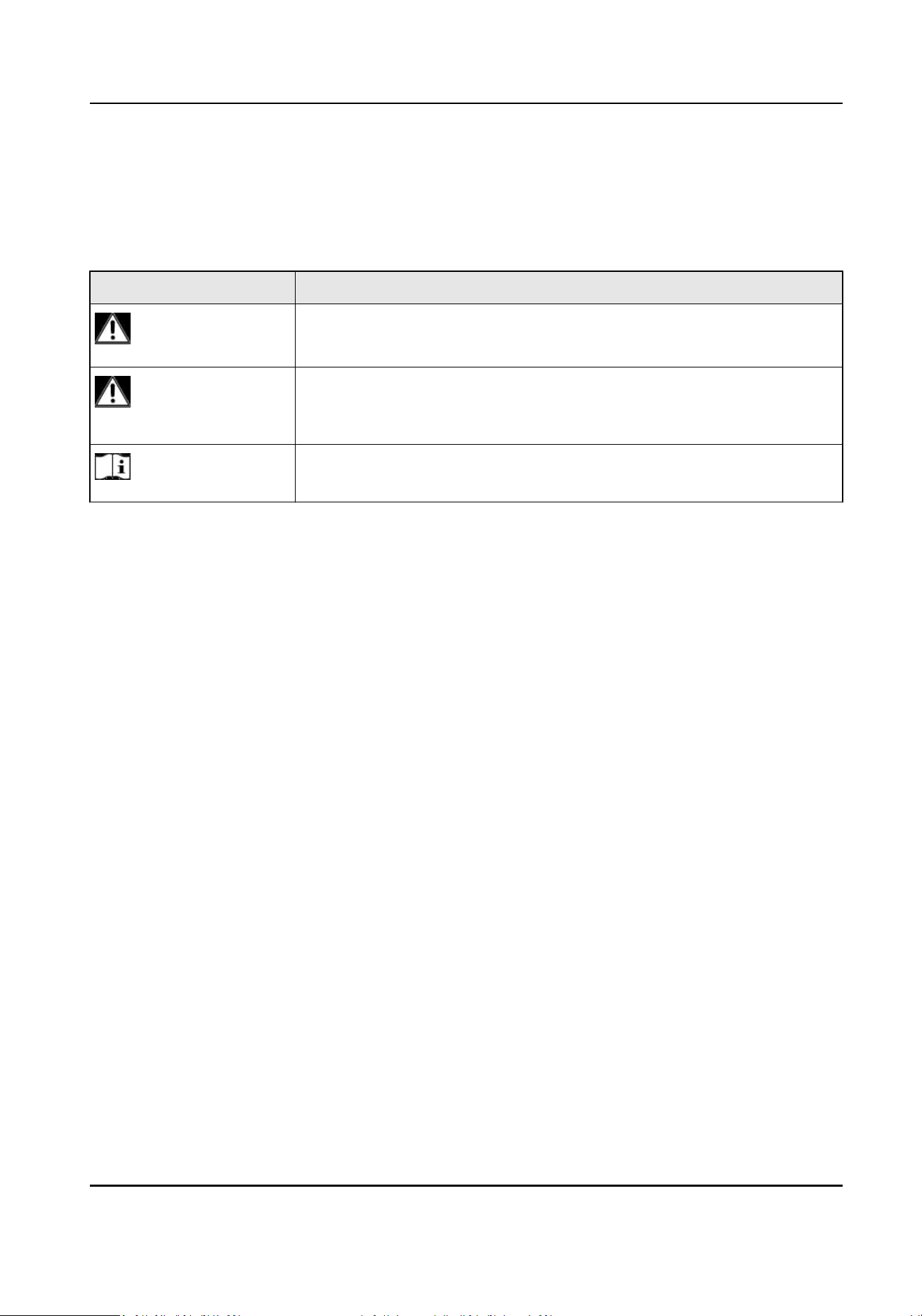
ALARM IN The alarm input receives alarm input signal. The equipment posive terminal
(+) should connect to a number, and the equipment negave terminal (-)
should connect to “-“ or “G”.
Use the following diagram as a
connecon example for alarm input.
ALARM OUT The alarm output sends out alarm signal.
When an equipment uses DC power supply, its posive terminal (+) should
connect to a number with “A”, and its negave terminal (-) should both
connect to the corresponding number with “B”, and then connect to “-“ or
“G”. Use the following diagram as an alarm output connecon example for DC
equipment.
Network Video Recorder User Manual
xvii
Item Descripon
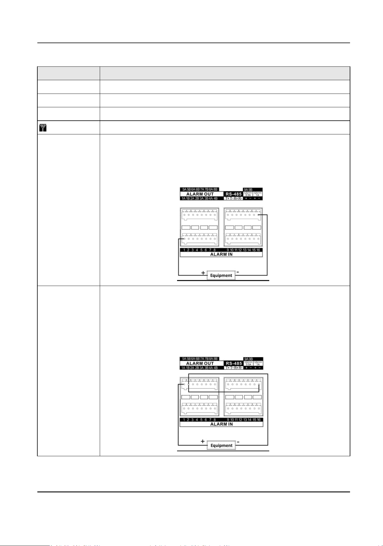
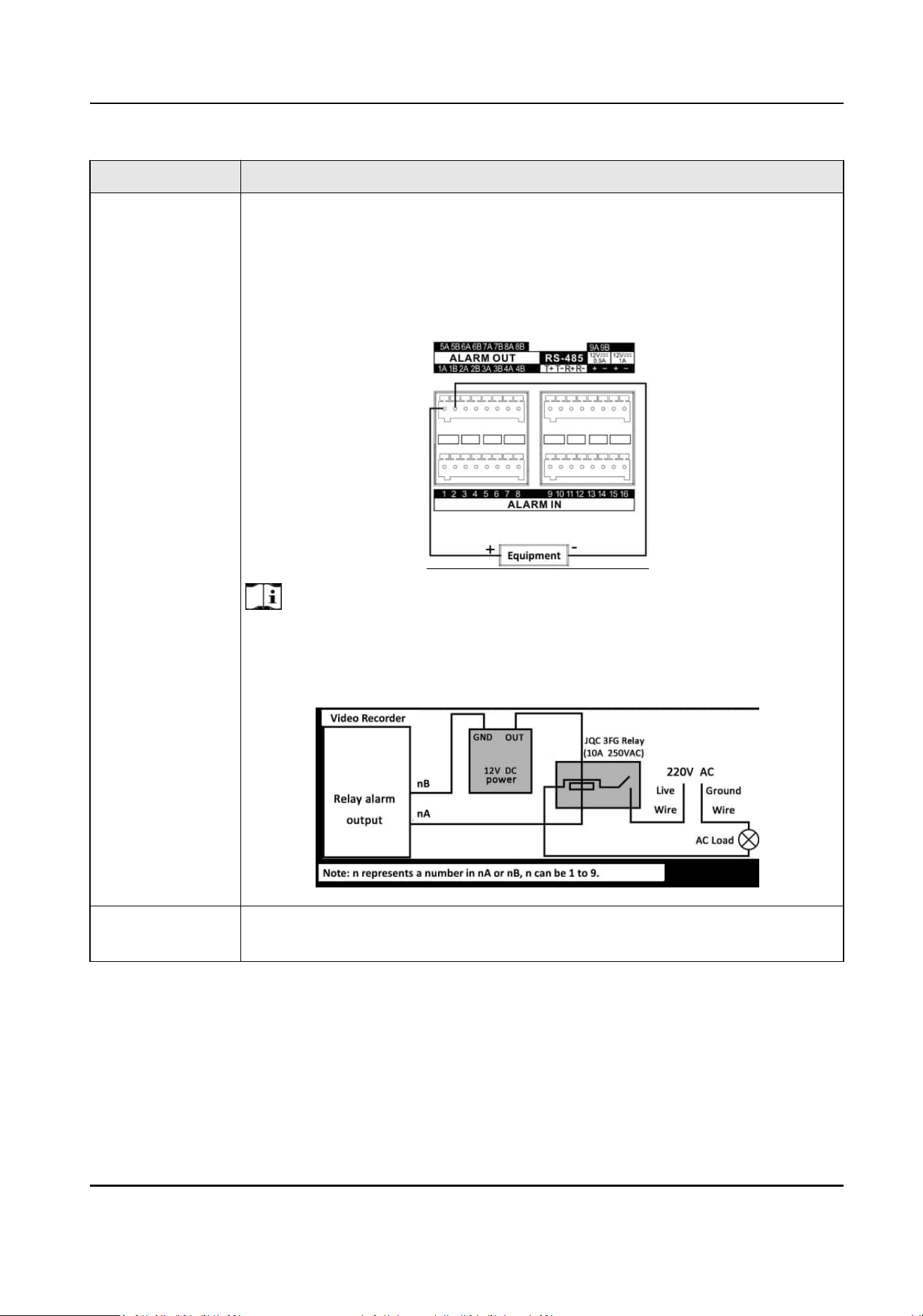
When an equipment uses AC power supply, its posive terminal (+) should
connect to a number with “A”, and its negave terminal (-) should connect to
the corresponding number with “B”.
Use the following diagram as an alarm output
connecon example for AC
equipment.
Note
For the reason that the AC load voltage could be high, please use an external
relay for safety.
Use the following diagram for reference.
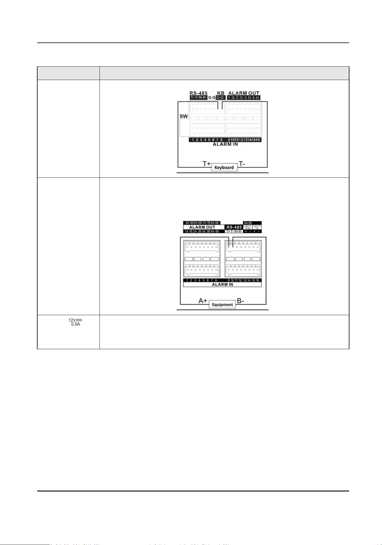
KB KB represents keyboard. Connect “D+” and “D-” to “T+” and “T-” respecvely.
Use the following diagram for reference.
Network Video Recorder User Manual
xviii
Item Descripon
RS-485 RS-485 is an electrical specicaon of a two-wire, half-duplex, mulpoint
serial connecon. Connect “T+” and “T-” to “A+” and “B-” respecvely.
Use the following diagram for reference.
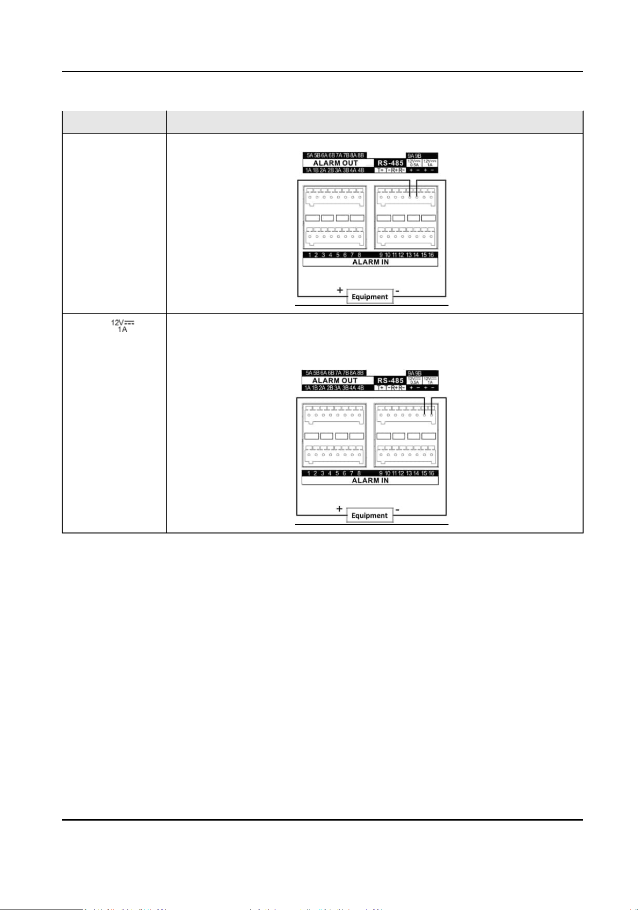
Ctrl 12V/ Controllable 12 VDC and 0.5/1 A power output for external alarm device. The
power will be turned on when the corresponding alarm output is triggered.
Use the following diagram for reference.
Network Video Recorder User Manual
xix
Item Descripon
DC 12V/ It provides 12 VDC and 1 A power output.
Use the following diagram for reference.
Network Video Recorder User Manual
xx

HDD Installaon
If your device does not support HDD hot swapping, disconnect the power from the device before
installing a hard disk drive (HDD). A factory recommended HDD should be used for this
installaon.
Scan the QR code below to view HDD installaon videos.
Figure 1-1 HDD Installaon
Bracket
Installaon
Bracket installaon is applicable when it requires to remove the device cover, and install HDD on
the internal bracket.
Steps
1.
Unfasten screws on the back, and push the cover backwards to remove the cover.
Network Video Recorder User Manual
xxi
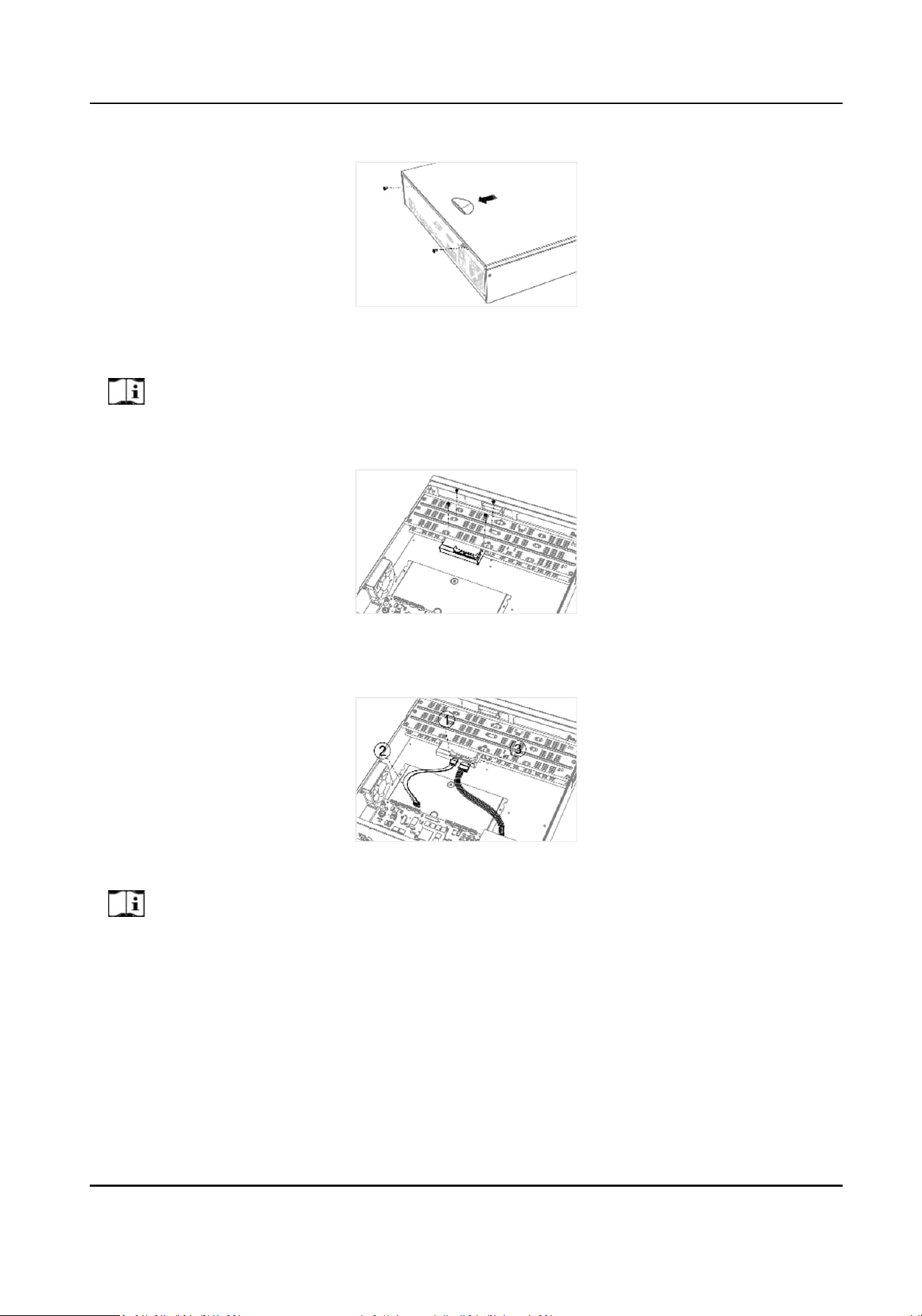
Figure 1-2 Remove Cover
2.
Fix the HDD on the bracket with screws.
Note
Please uninstall the upper layer bracket rst before installing HDD on the lower layer bracket.
Figure 1-3 Fix HDD
3.
Connect the data cable and power cable.
Figure 1-4 Connect Cable
Note
You can repeat the steps above to install other HDDs.
4.
Reinstall the device cover and fasten screws.
Front Panel Plug-Pull
Installaon
Front panel plug-pull installaon is applicable when you need to open the device front panel with
key and install the HDD.
Network Video Recorder User Manual
xxii
Steps
1.
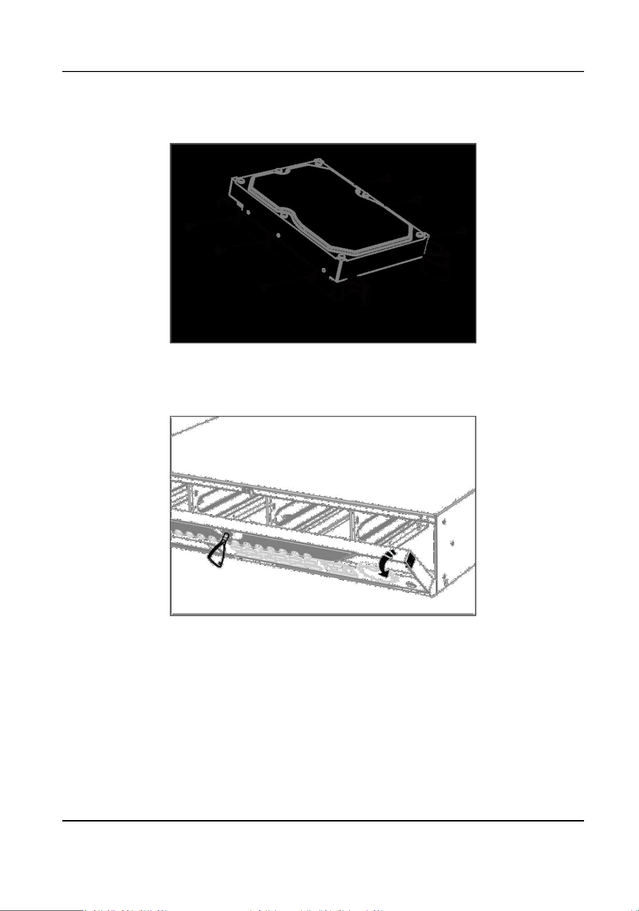
Fix mounng ears to HDD with screws.
Figure 1-5 Fix Mounng Ears to HDD
2.
Unlock the front panel with the aached key, and press the buons on both sides of the front
panel to open it.
Figure 1-6 Open Front Panel
3.
Insert the HDD unl it is xed rmly.
Network Video Recorder User Manual
xxiii
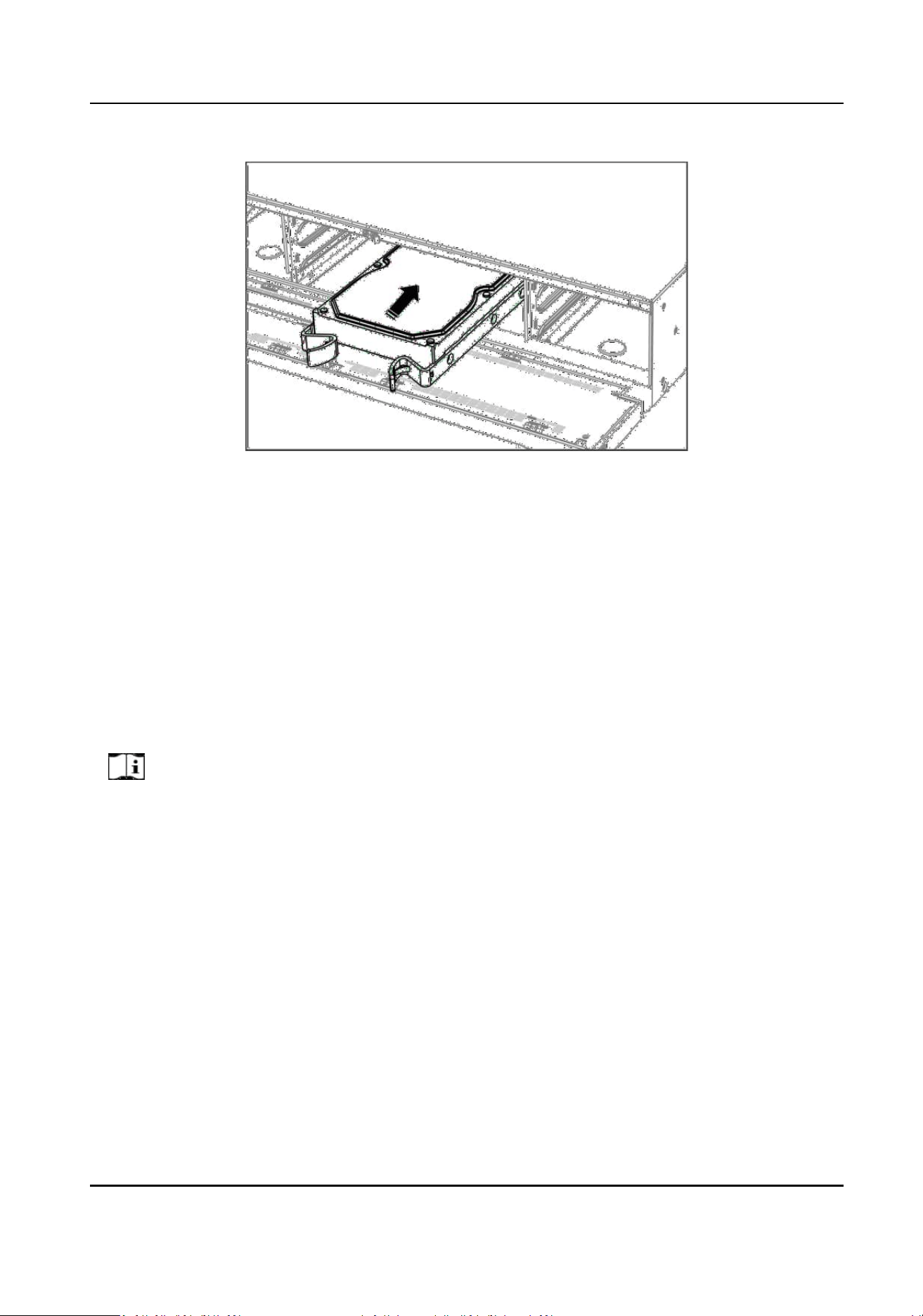
Figure 1-7 Insert HDD
4.
Oponal: Repeat the steps above to install other HDDs.
5.
Close the front panel and lock it with key.
HDD Case
Installaon
HDD case installaon refers to the method that you install the HDD in the case, and then plug the
HDD case into the slot.
Steps
1.
Unlock the front panel with panel key.
2.
Pull the front panel out of the device and make it a
lile above the le handle.
Note
The angle between the front panel and the device must be within 10°.
3.
Press the blue buon to pop up the handle and hold the handle and pull the HDD case out of
the slot.
4.
Fix the hard disk in the HDD case.
1) Place a HDD in the case. The SATA interface must face the case
boom.
2) Adjust the HDD posion. Ensure the hard disk rear aligns with HDD boom.
3) Use a screwdriver to fasten the four screws into the screw holes in both sides.
Network Video Recorder User Manual
xxiv
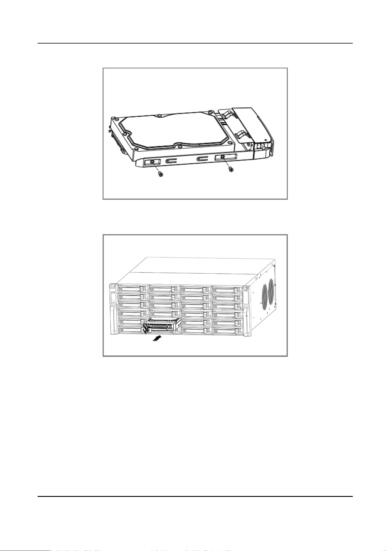
Figure 1-8 Fix HDD
5.
Push the HDD case back into the slot.
Figure 1-9 Push HDD Case into Slot
6.
Press the handle unl you hear a click. Thus to x the HDD case. Repeat above steps to install
the rest hard disk boxes.
7.
Close the front panel, and lock it with the panel key.
Fix-on-Boom
Installaon
Fix-on-boom installaon is applicable when you need to install and x the HDD on the device
boom.
Network Video Recorder User Manual
xxv
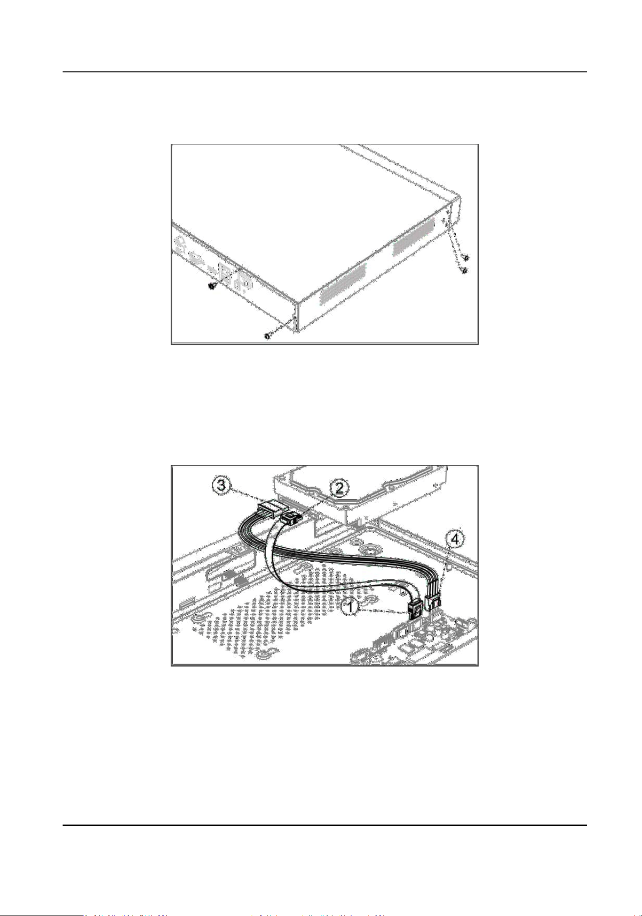
Steps
1.
Remove the cover from device by unfastening the screws on panels.
Figure 1-10 Remove Cover
2.
Connect the data cable and power cable.
1) Connect one end of data cable to the device motherboard.
2) Connect the other end of data cable to HDD.
3) Connect one end of power cable to HDD.
4) Connect the other end of power cable to the device motherboard.
Figure 1-11 Connect Cables
3.
Set the device up, match HDD screw threads with the reserved holes on the device boom, and
x HDD with screws.
Network Video Recorder User Manual
xxvi
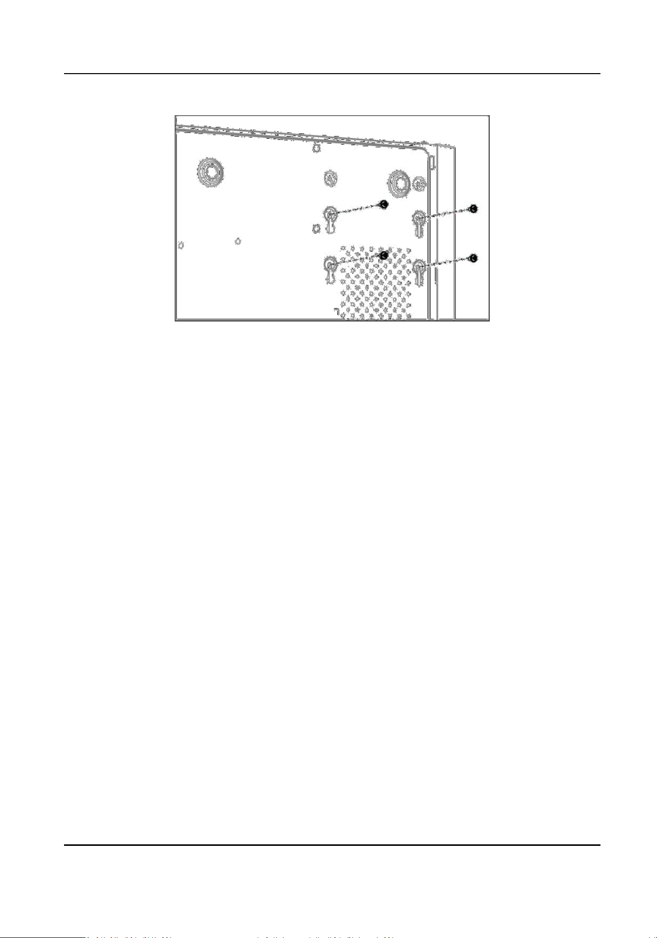
Figure 1-12 Fix HDD to Device Boom
4.
Oponal: Repeat the steps above to install other HDDs.
5.
Reinstall the device cover and fasten screws.
Network Video Recorder User Manual
xxvii
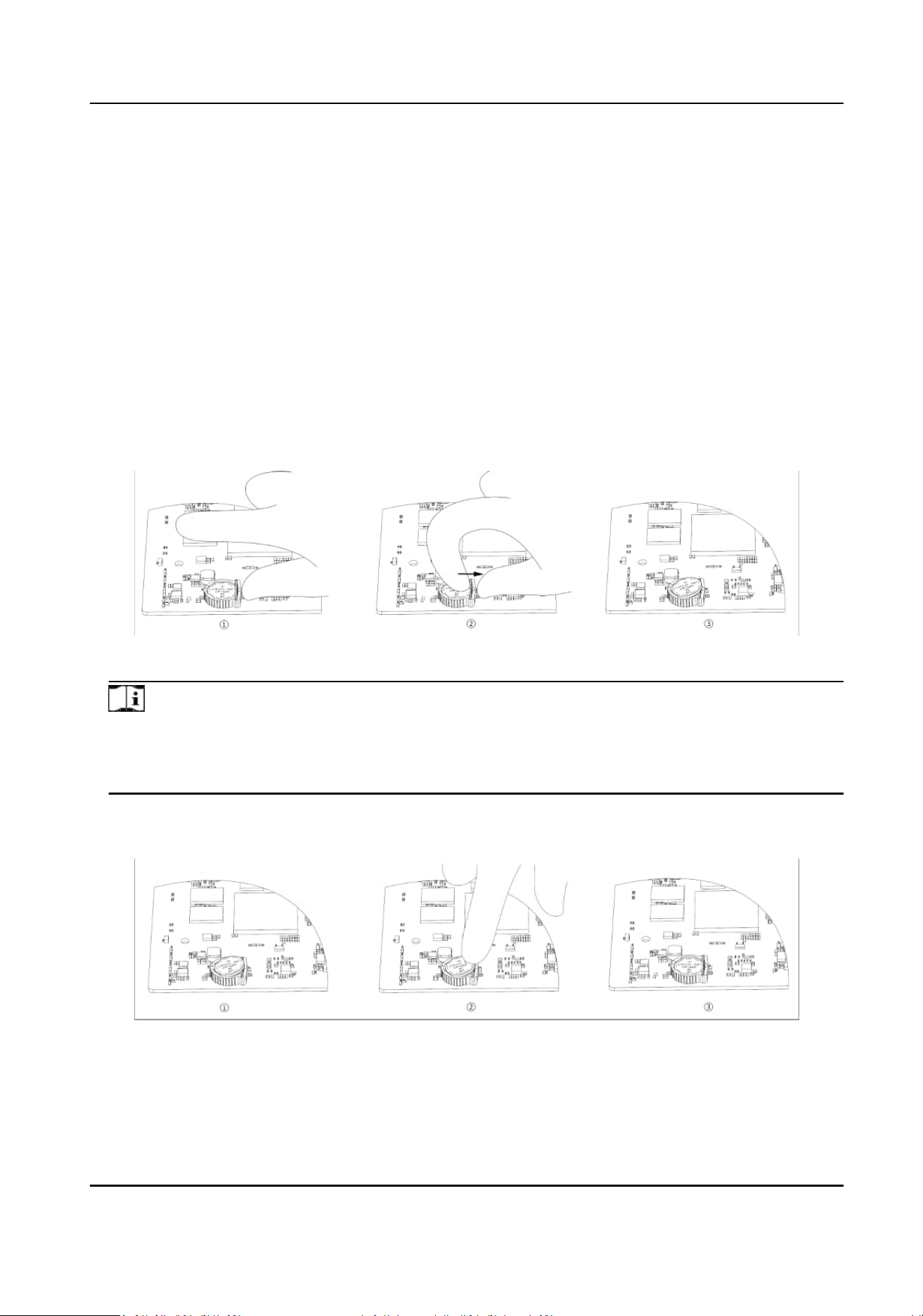
Coin/Buon Cell Baery Replacement
The coin/buon cell baery should be replaced when the device has been powered o or placed
for a long
me, and the system me is incorrect.
Before You Start
Power o your device.
Steps
1.
Remove the device chassis cover.
2.
Find the
coin/buon cell baery on motherboard.
3.
Put the thumb outside the baery slot, and use the index nger to push the posive contact
spring outward gently. The
baery will pop up automacally.
Figure 1-1 Remove Baery
Note
●
You should wear an-stac gloves when removing the baery.
●
If the spring is deformed due to excessive force when pushing outward, it needs to be
adjusted back into its original posion before inserng the baery.
4.
Insert the baery diagonally towards the side with the plasc snap point in the baery slot, and
then press the baery near the posive contact spring to snap it beneath the spring.
Figure 1-2 Replace Baery
Network Video Recorder User Manual
xxviii

Note
You should wear an-stac gloves when replacing the baery.
5.
Reinstall the device chassis cover.
What to do next
If the system me is incorrect, please go to congure the me.
Network Video Recorder User Manual
xxix

Contents
Chapter 1 Acvate via Local Menu .............................................................................................. 1
Chapter 2 Log In to Your Device .................................................................................................. 3
Chapter 3 User Interface Introduce ............................................................................................. 4
Chapter 4 Network Sengs ........................................................................................................ 6
4.1 Network Parameter Sengs .................................................................................................. 6
4.1.1 Congure TCP/IP ........................................................................................................... 6
4.1.2 Congure DDNS ............................................................................................................ 7
4.1.3 Congure PPPoE ............................................................................................................ 8
4.1.4
Congure Mulcast ....................................................................................................... 9
4.2 Plaorm Access Sengs ........................................................................................................ 9
4.2.1 Congure Hik-Connect .................................................................................................. 9
4.2.2
Congure OTAP ........................................................................................................... 11
4.2.3 Congure ISUP ............................................................................................................ 12
4.2.4 Congure SDK Service ................................................................................................. 13
4.2.5 Enable ISAPI ................................................................................................................ 14
4.2.6
Congure ONVIF ......................................................................................................... 14
4.2.7 Congure Log Server ................................................................................................... 15
4.3 Network Service
Sengs ..................................................................................................... 16
4.3.1 Congure HTTP(S) ....................................................................................................... 16
4.3.2 Congure RTSP ............................................................................................................ 17
4.3.3
Congure WebSocket(s) .............................................................................................. 18
4.3.4 Congure Port Mapping (NAT) .................................................................................... 18
4.3.5 Congure IoT ............................................................................................................... 20
Chapter 5 User Management .................................................................................................... 21
Chapter 6 Device Access ........................................................................................................... 22
6.1 Access Video Device ............................................................................................................. 22
Network Video Recorder User Manual
xxx

6.1.1 Add Automacally Searched Online Network Camera ............................................... 22
6.1.2 Add Network Camera Manually .................................................................................. 23
6.1.3 Add Network Camera through PoE ............................................................................. 24
6.1.4 Add Solar-Powered Camera through OTAP Protocol ................................................... 24
6.1.5 Add Network Camera via Custom Protocol ................................................................. 25
6.1.6 Add Network Camera through Camera
Conguraon File ......................................... 26
6.2 Add Access Control Device ................................................................................................... 26
6.3 Add Security Control Panel .................................................................................................. 27
6.4 Add Audio Device ................................................................................................................. 27
6.5 Add POS Device .................................................................................................................... 27
6.6 Channel Management ......................................................................................................... 29
Chapter 7 Device Grouping ....................................................................................................... 30
Chapter 8 Video or Audio Device
Sengs ................................................................................. 31
8.1 Enable H.265 Stream Access ................................................................................................ 31
8.2
Congure Display Sengs .................................................................................................... 31
8.3 Congure Video Parameters ................................................................................................ 32
8.4
Congure Privacy Mask ........................................................................................................ 32
8.5 Congure Privacy Protecon ............................................................................................... 33
8.6 Congure Audio Parameter ................................................................................................. 35
8.7
Congure OTAP Service ........................................................................................................ 35
8.8 Batch Conguraon ............................................................................................................. 36
8.9 Congure PoE (Power over Ethernet) Interface ................................................................... 37
Chapter 9 Storage Management ............................................................................................... 38
9.1 Manage HDD ........................................................................................................................ 38
9.2 RAID
Conguraon .............................................................................................................. 38
9.2.1 Create Disk Array ......................................................................................................... 39
9.2.2 Rebuild Array ............................................................................................................... 41
9.2.3 Delete Array ................................................................................................................ 41
Network Video Recorder User Manual
xxxi

9.2.4 View Firmware Info ..................................................................................................... 41
9.3 Congure Storage Mode ...................................................................................................... 42
9.4
Congure Other Storage Parameters ................................................................................... 42
9.5 Mange USB Flash Drive ........................................................................................................ 43
Chapter 10 Schedule Conguraon ........................................................................................... 44
10.1 Congure Schedule Template ............................................................................................ 44
10.2 Congure Recording Schedule ........................................................................................... 46
10.3 Congure Picture Capture Schedule .................................................................................. 48
10.4 Congure Audio Recording ................................................................................................ 50
Chapter 11 Live View ................................................................................................................ 51
11.1 Congure Live View Layout ................................................................................................ 51
11.2 GUI Introducon ................................................................................................................ 51
11.3 PTZ Control ........................................................................................................................ 53
Chapter 12 Playback ................................................................................................................. 54
12.1 GUI Introducon ................................................................................................................ 54
12.2 Normal Playback ................................................................................................................ 55
12.3 Event Playback ................................................................................................................... 56
12.4 Slice Playback ..................................................................................................................... 57
12.5 Sub-Period Playback ........................................................................................................... 57
Chapter 13 Event Center ........................................................................................................... 59
13.1 Event
Sengs ..................................................................................................................... 59
13.1.1 Basic/Generic Event .................................................................................................. 59
13.1.2 Perimeter
Protecon ................................................................................................ 61
13.1.3 Abnormal Behavior Event ......................................................................................... 72
13.1.4 Target Event .............................................................................................................. 75
13.1.5 Thermal Camera
Detecon ....................................................................................... 77
13.1.6 Alarm Input Event ..................................................................................................... 78
13.1.7 Audio Analysis Event ................................................................................................. 80
Network Video Recorder User Manual
xxxii

13.2 Linkage Conguraon ........................................................................................................ 82
13.3 Disarming Conguraon .................................................................................................... 84
13.4 Batch
Conguraon ........................................................................................................... 85
13.5 Event Search ...................................................................................................................... 86
13.6 View Alarms ....................................................................................................................... 87
Chapter 14 Search and Backup .................................................................................................. 88
Chapter 15 AcuSeek .................................................................................................................. 90
Chapter 16 AcuSearch ............................................................................................................... 93
Chapter 17 Smart Sengs ........................................................................................................ 95
17.1 Algorithm Management ..................................................................................................... 95
17.2 Engine Status ..................................................................................................................... 95
17.3 Task Plan Management ...................................................................................................... 95
17.4 List library Management .................................................................................................... 96
17.4.1 Add a List Library ....................................................................................................... 96
17.4.2 Upload Face Pictures to the Library .......................................................................... 96
17.5 Self-Learning Sengs ......................................................................................................... 97
17.5.1 Self-Learning Task Management ............................................................................... 97
17.5.2 Model Management ................................................................................................. 98
17.5.3 Smart Status .............................................................................................................. 98
Chapter 18
Applicaon Center .................................................................................................. 99
18.1 Human and Vehicle Detecon ........................................................................................... 99
18.2 Person Check-In ................................................................................................................. 99
18.2.1 Add Check-In Task ................................................................................................... 100
18.2.2 Search Check-In Records ......................................................................................... 101
18.3
Stasc Report ................................................................................................................. 101
Chapter 19 System Parameter
Sengs .................................................................................... 103
Chapter 20 Hot Spare Device Backup ...................................................................................... 105
20.1 Set Working Device .......................................................................................................... 105
Network Video Recorder User Manual
xxxiii

20.2 Set Hot Spare Device ........................................................................................................ 105
Chapter 21 Congure Excepon Event .................................................................................... 107
Chapter 22 View System Info .................................................................................................. 109
Chapter 23 System Maintenance ............................................................................................ 110
23.1 Schedule Reboot .............................................................................................................. 110
23.2 Upgrade Device ................................................................................................................ 110
23.3 Backup and Restore ......................................................................................................... 110
23.4 Log Info ............................................................................................................................ 111
23.5
Congure Log Server ........................................................................................................ 111
23.6 Maintenance Tools ........................................................................................................... 111
23.7 So Power O Conguraon ........................................................................................... 112
Chapter 24 Security Management ........................................................................................... 114
24.1 Address Filter ................................................................................................................... 114
24.2 Stream Encrypon ........................................................................................................... 114
24.3 Select TLS Version ............................................................................................................ 114
Chapter 25 Appendix .............................................................................................................. 115
25.1 List of Applicable Power Adapter ..................................................................................... 115
25.2 Glossary ........................................................................................................................... 116
25.3 Frequently Asked
Quesons ............................................................................................ 117
25.3.1 Why is there a part of channels displaying “No Resource” or turning black screen in
mul-screen live view? ...................................................................................................... 117
25.3.2 Why is the video recorder
nofying risky password aer a network camera is added?
............................................................................................................................................ 118
25.3.3 Why is the video recorder nofying the stream type is not supported? ................ 118
25.3.4 How to conrm the video recorder is using H.265 to record video? ...................... 118
25.3.5 Why is the video recorder nofying IP conict? ..................................................... 118
25.3.6 Why is image
geng stuck when playing back by single or mul-channel cameras?
............................................................................................................................................ 119
25.3.7 Why is the device not able to control PTZ camera via coaxitron? .......................... 119
Network Video Recorder User Manual
xxxiv

25.3.8 Why does the PTZ seem unresponsive via RS-485? ................................................ 119
25.3.9 Why is the video sound quality not good? .............................................................. 119
25.4
Nocaon for Corrosive Gas .......................................................................................... 120
Network Video Recorder User Manual
xxxv

Chapter 1 Acvate via Local Menu
For the rst-me access, you have to set an admin password to acvate your device. No operaon
is allowed before acvaon. You can also acvate the device via web browser, SADP or client
soware.
Before You Start
Ensure your device is connected with a monitor and mouse.
Steps
1.
Power on your device.
2.
Set the region or DST (Daylight Saving Time) parameters.
3.
Select a system language.
4.
Enter the admin password twice.
Cauon
We highly recommend you to create a strong password of your own choosing (using a minimum
of 8 characters, including at least three kinds of following categories: upper case leers, lower
case leers, numbers, and special characters) in order to increase the security of your product.
And we recommend you change your password regularly, especially in the high security system,
changing the password monthly or weekly can beer protect your product.
Network Video Recorder User Manual
1
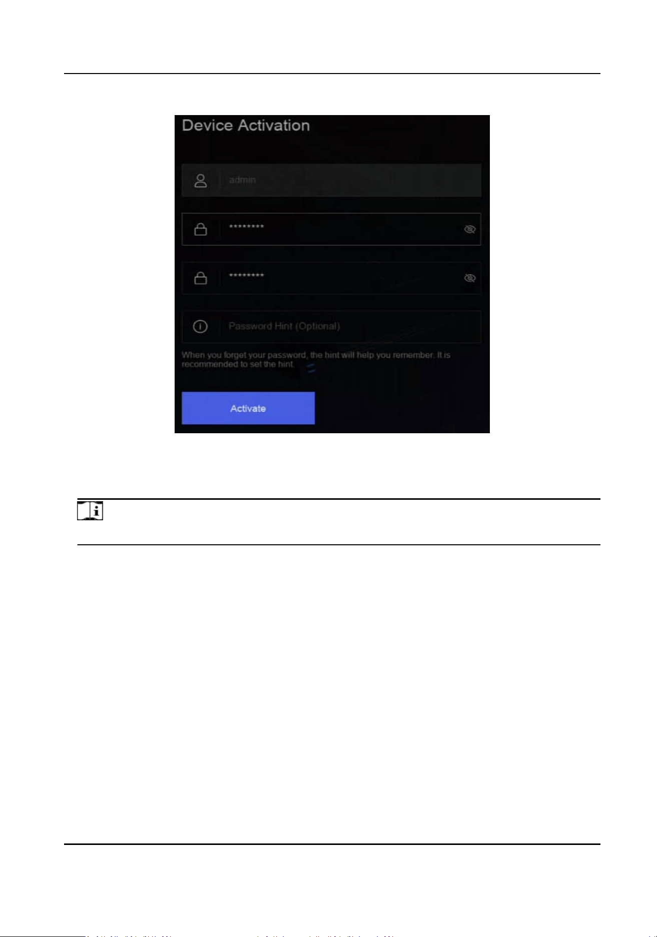
Figure 1-1 Acvate via Local Menu
5.
Oponal: Enter a password hint. It will help you remember your password when you forget.
6.
Click
Acvate.
Note
Aer the device is acvated, you should properly keep the password.
7.
Oponal: Draw an unlock paern.
8.
Congure at least one password recovery method.
What to do next
Follow the wizard to set basic parameters.
Network Video Recorder User Manual
2

Chapter 2 Log In to Your Device
You have to log in to your device before operang the menu and other funcons.
Before You Start
Ensure your device is
acvated.
Steps
1.
Power on your device.
2.
Right click to display the shortcut menu.
3.
Select an item as needed. For example, select Exit Full Screen, and you would
automacally
enter the login interface.
Figure 2-1 Login
4.
Use the unlock paern to log in, or click Password Login to log in via user name and password.
Note
●
Unlock paern is only available for admin user.
●
If you forget your unlock paern or login password, click Forget Password at the password
login interface to reset your password, or use the password hint to remember.
Network Video Recorder User Manual
3
Chapter 3 User Interface Introduce
The device will enter the live view interface aer it is powered on. Right click your mouse and
select Exit Full Screen through the shortcut menu.
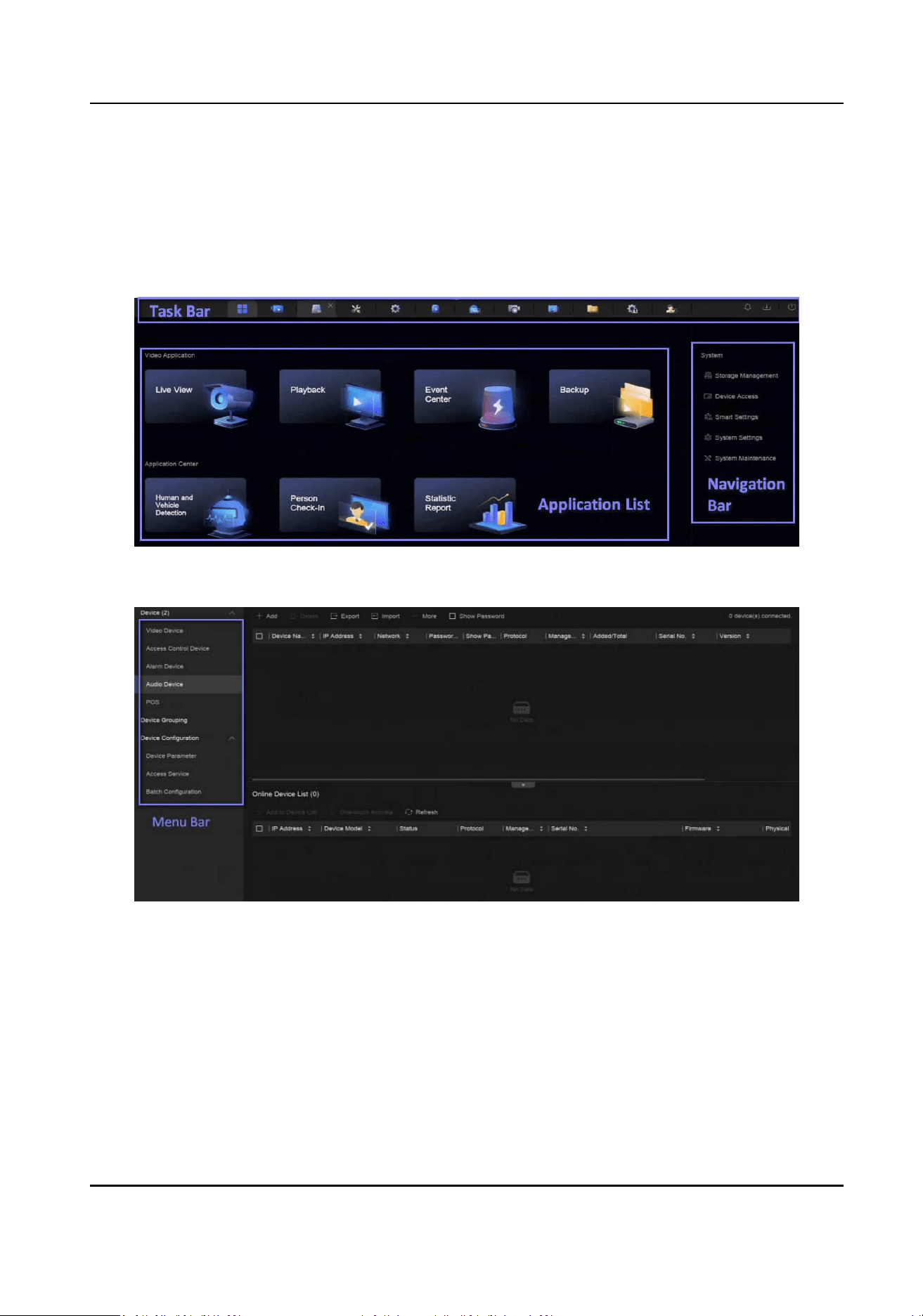
Figure 3-1 Main Funcon Page
Figure 3-2 Menu Bar Example
Network Video Recorder User Manual
4
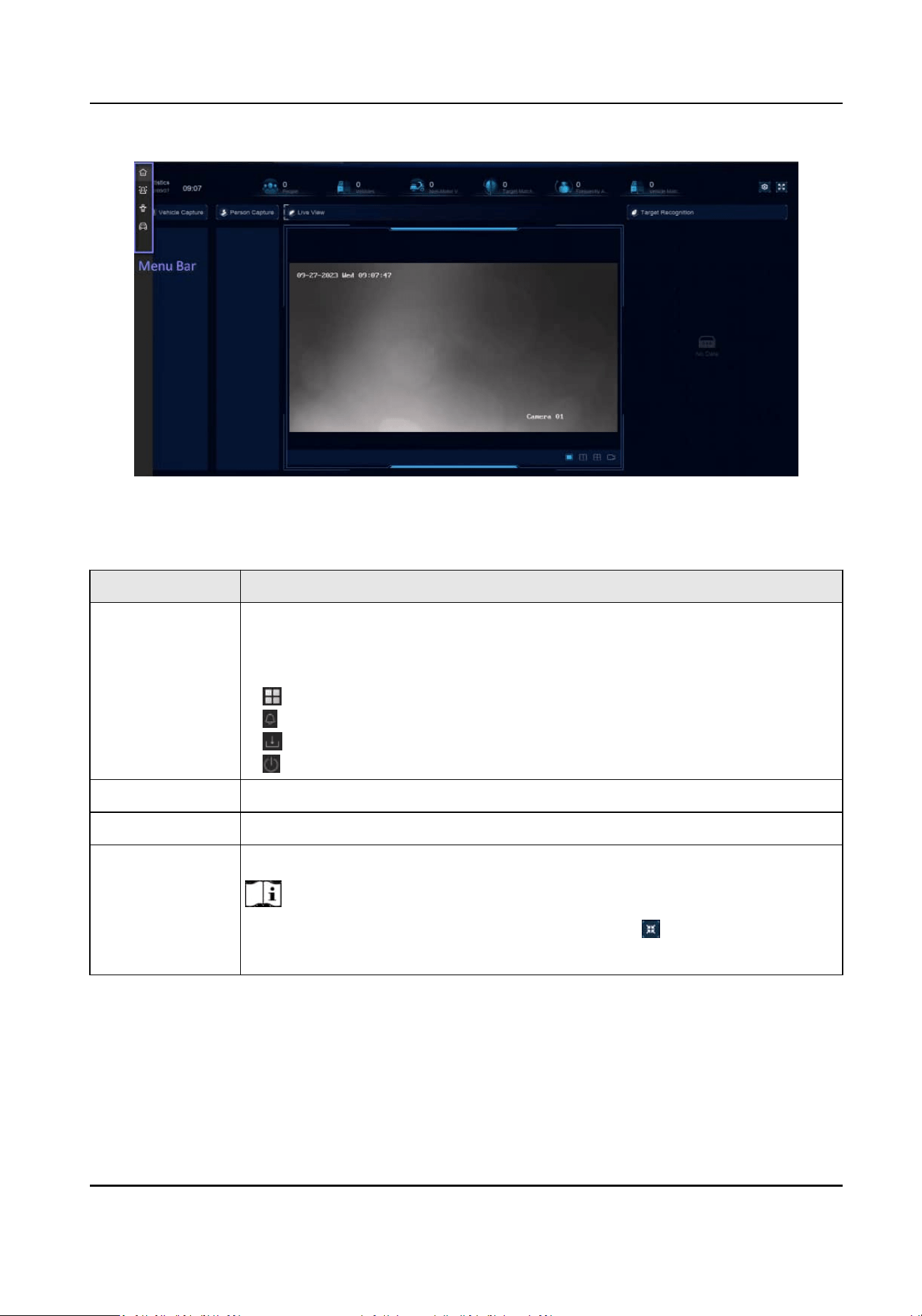
Figure 3-3 Human and Vehicle Detecon Example of Applicaon Center
Table 3-1 Interface Introducon
Interface Name Introducon
Task Bar The opened applicaons are listed in the task bar. You can move and close
each applicaon tab.
Icon introducon:
●
: Main menu.
●
: Event center. Event alarms can be searched and viewed.
●
: The download progress of each download task can be viewed here.
●
: Shut down, log out, or reboot your device.
Applicaon List All applicaons are displayed here. You can click one to congure it.
Navigaon Bar Click to congure each funcon of the system.
Menu Bar Congurable items of each applicaon are listed here.
Note
For applicaons in Applicaon Center, you can click , or right click to
display the menu bar.
Network Video Recorder User Manual
5
Chapter 4 Network Sengs
Network parameters, plaorm access sengs, and network services are congurable.
4.1 Network Parameter Sengs
You shall congure network parameters before using funcons that require network access.
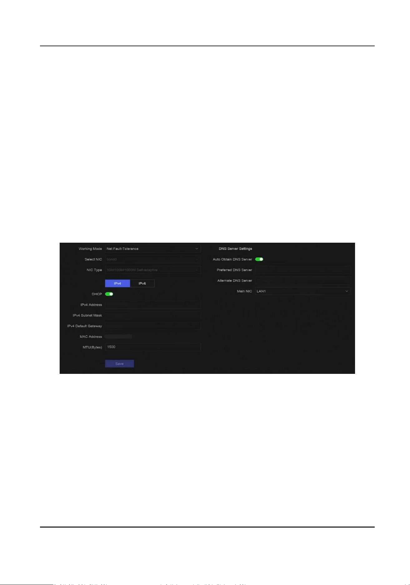
4.1.1 Congure TCP/IP
TCP/IP must be properly congured before you operate video recorder over network or access
network devices.
Steps
1.
Go to System → System
Sengs → Network → Network → TCP/IP .
Figure 4-1 TCP/IP Sengs
2.
Set Working Mode and Select NIC.
Mul-address
The parameters of the two NIC cards can be congured independently. You can select LAN1
or LAN2 in the NIC type
eld for parameter sengs. You can select one NIC card as default
route. And then the system is connecng with the extranet and the data will be forwarded
through the default route.
Net-fault Tolerance
Network Video Recorder User Manual
6

The two NIC cards use the same IP address, and you can set Main NIC to LAN1 or LAN2. By
this way, in case of one NIC card failure, the video recorder will automacally enable the
other standby NIC card so as to ensure the normal running of the whole system.
Note
Working mode is only available for certain models.
3.
Congure network parameters.
-
IPv4
DHCP
If the DHCP server is available, you can enable DHCP to automacally obtain an IP address
and other network sengs from that server.
MTU
The maximum transmission unit (MTU) is the size of the largest network layer protocol
data unit that can be communicated in a single network
transacon.
Auto Obtain DNS Server
If DHCP is enabled. You can check Auto Obtain DNS Server to obtain Preferred DNS Server
and Alternate DNS Server.
-
IPv6
Router Adversement
If the router in the network supports IPv6, it is recommended to use this mode as default.
Auto
If there is a DHCPv6 device in the network, it is recommended to use this mode
Manual Conguraon
You shall use this mode if you are going to manually enter IPv6 parameters.
4.
Click Save.
4.1.2
Congure DDNS
Dynamic domain name server (DDNS) maps dynamic user IP addresses to a xed domain name
server.
Before You Start
Ensure you have registered DynDNS, PeanutHull, and NO-IP services with your ISP.
Steps
1.
Go to System → System
Sengs → Network → Network → DDNS .
Network Video Recorder User Manual
7
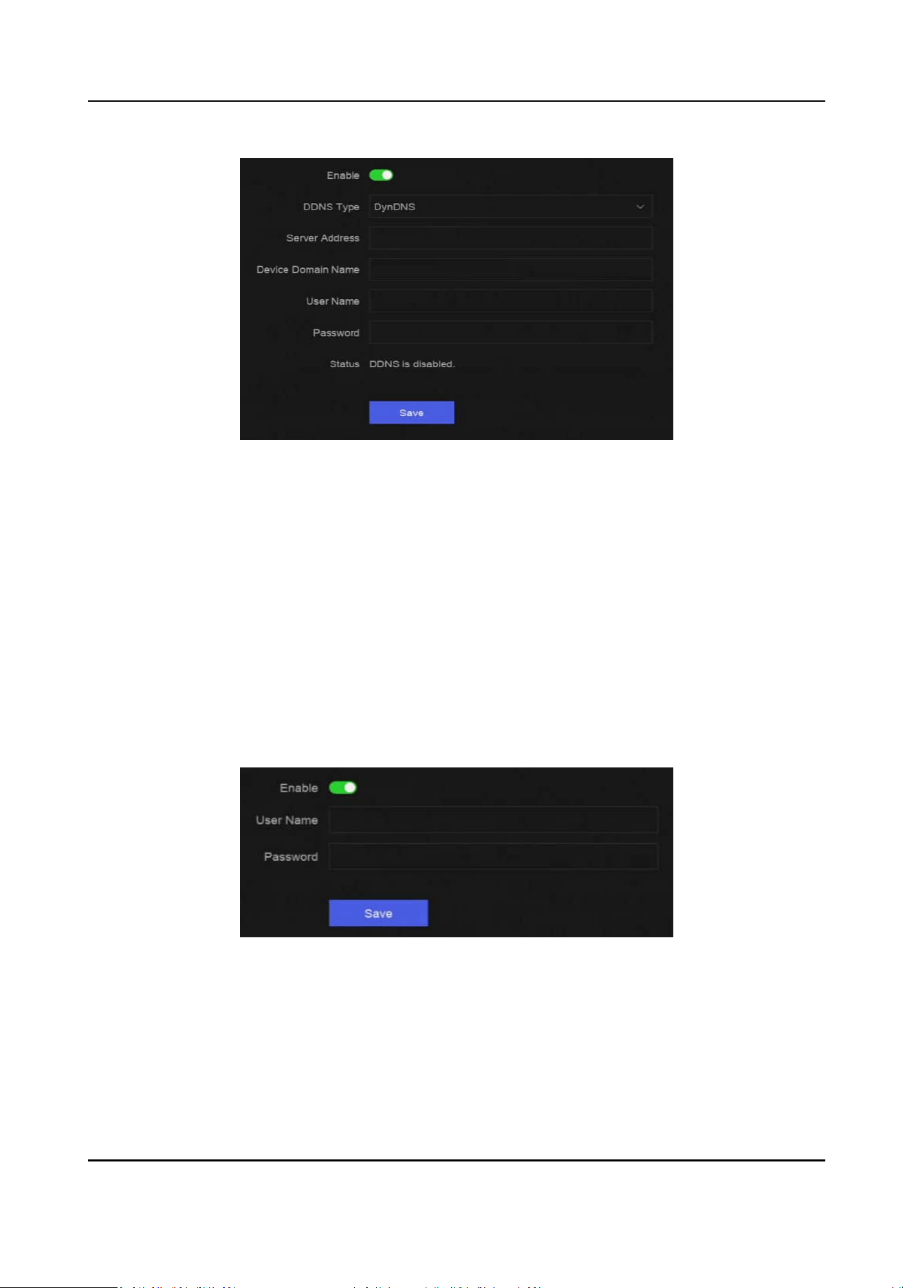
Figure 4-2 DDNS
2.
Turn on Enable.
3.
Select a DDNS type.
4.
Set parameters, including service address, domain name, etc.
5.
Click Save.
4.1.3
Congure PPPoE
If the device is connected to Internet through PPPoE, you need to congure user name and
password accordingly. Contact your Internet service provider for details about PPPoE service.
Steps
1.
Go to System → System Sengs → Network → Network → PPPoE .
Figure 4-3 PPPoE
2.
Turn on Enable.
3.
Enter user name and password.
4.
Click Save.
What to do next
Go to System → System Maintenance → Running Info → Network Status to view PPPoE status.
Network Video Recorder User Manual
8

4.1.4 Congure Mulcast
Mulcast can be congured to enable live view for cameras that exceed the maximum number
allowed through network.
Steps
1.
Go to System → System
Sengs → Network → Network → Other .
2.
Set Mulcast parameters.
Note
●
When adding device through network video security client, mulcast group IP address should
be the same as the device mulcast IP address.
●
For IPv4, it covers Class-D IP ranging from 224.0.0.0 to 239.255.255.255 and it is
recommended to use an IP address ranging from 239.252.0.0 to 239.255.255.255. When
adding a device to the CMS soware, the mulcast address must be the same as that of the
device.
3.
Click Save.
4.2
Plaorm Access Sengs
4.2.1 Congure Hik-Connect
Hik-Connect provides mobile phone applicaon and plaorm service to access and manage your
video recorder, which enables you to get a convenient remote access to the video security system.
Steps
1.
Go to System → System
Sengs → Network → Hik-Connect.
Network Video Recorder User Manual
9
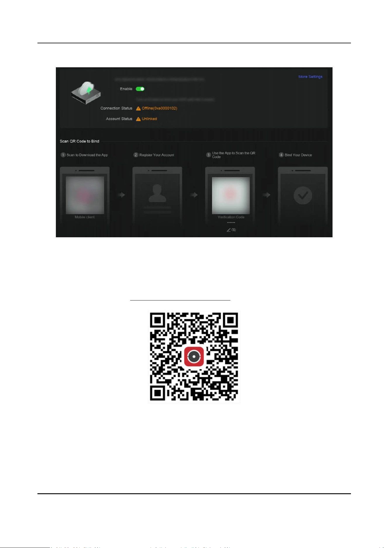
Figure 4-4 Hik-Connect
2.
Turn on Enable, and the service terms will pop up.
3.
Accept the service terms.
4.
Download Hik-Connect app.
-
Use a smart phone to scan the QR code, and download Hik-Connect app.
-
Download the app from hps://appstore.hikvision.com .
Figure 4-5 Download Hik-Connect
5.
Register an account at the app.
6.
Oponal: Click More Sengs to enable Stream Encrypon, Plaorm Time Sync, and Adapve
Bitrate Streaming, or edit Server IP Address.
Stream
Encrypon
Network Video Recorder User Manual
10

It requires to enter vericaon code in remote access and live view aer this funcon is
enabled.
Plaorm Time Sync
The device will sync me with Hik-Connect instead of NTP server.
Adapve Bitrate Streaming
When the network environment is poor, the device would automacally adjust video bitrate
to ensure playing uency.
Server IP Address
The Hik-Connect server IP address.
7.
Click to set vericaon code.
8.
Use Hik-Connect app to scan the device QR, and bind the device with your Hik-Connect account.
Note
If the device is already bound with an account, you can click Unbind to unbind with the current
account.
Result
●
If your device is connected with Hik-Connect,
Connecon Status will be Online.
●
If your device is bound with a Hik-Connect account, Account Status will be Linked.
What to do next
You can access your video recorder via Hik-Connect.
4.2.2
Congure OTAP
OTAP (Open Thing Access Protocol) is an unied integrated standard and push-pull mode of
Hikvision protocol in the public network and private network.
Aer OTAP is enabled, other
applicaons may be able to remotely view videos through this protocol.
Before You Start
Ensure your device network is accessible through OTAP.
Steps
1.
Go to System → System Sengs → Network → Plaorm Access → OTAP .
Network Video Recorder User Manual
11
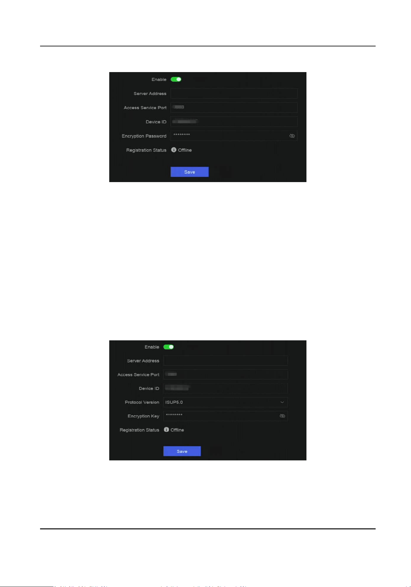
Figure 4-6 OTAP
2.
Turn on OTAP.
3.
Set the parameters.
4.
Click Save.
4.2.3
Congure ISUP
ISUP (Intelligent Security Uplink Protocol) provides APIs, library les, and commands for the third-
party plaorm to access devices such as NVRs, speed domes, DVRs, network cameras, mobile
NVRs, mobile devices, decoding devices, etc. With this protocol, the third-party plaorm can
realize
funcons like live view, playback, two-way audio, PTZ control, etc.
Steps
1.
Go to System → CX → System Sengs → Network → Plaorm Access → ISUP .
Figure 4-7 ISUP
2.
Turn on Enable.
Network Video Recorder User Manual
12

Note
If ISUP is enabled, the Hik-Connect access will automacally be disabled.
3.
Set the related parameters.
Server Address
The
plaorm server IP address.
Access Server Port
The
plaorm server port, ranges from 1024 to 65535. The actual port shall be provided by
the plaorm.
Device ID
Device ID shall be provided by the plaorm.
Protocol Version
ISUP protocol version, only ISUP 5.0 is available.
Encrypon Key
Encrypon password is required when using ISUP V5.0 version, it provides more secure
communicaon between the device and plaorm. Enter it for vericaon aer the device is
registered to the ISUP
plaorm. It cannot be empty, or "ABCDEF".
4.
Click Save.
You can see the
registraon status (online or oine) aer the device is restarted.
4.2.4
Congure SDK Service
SDK (Soware Development Kit) service is used for third-party partners to integrate dierent
funcons.
The enhanced SDK service adopts TLS protocol over the SDK service that provides safer
data transmission.
Steps
1.
Go to System → System Sengs → Network → Plaorm Access → SDK.
Network Video Recorder User Manual
13
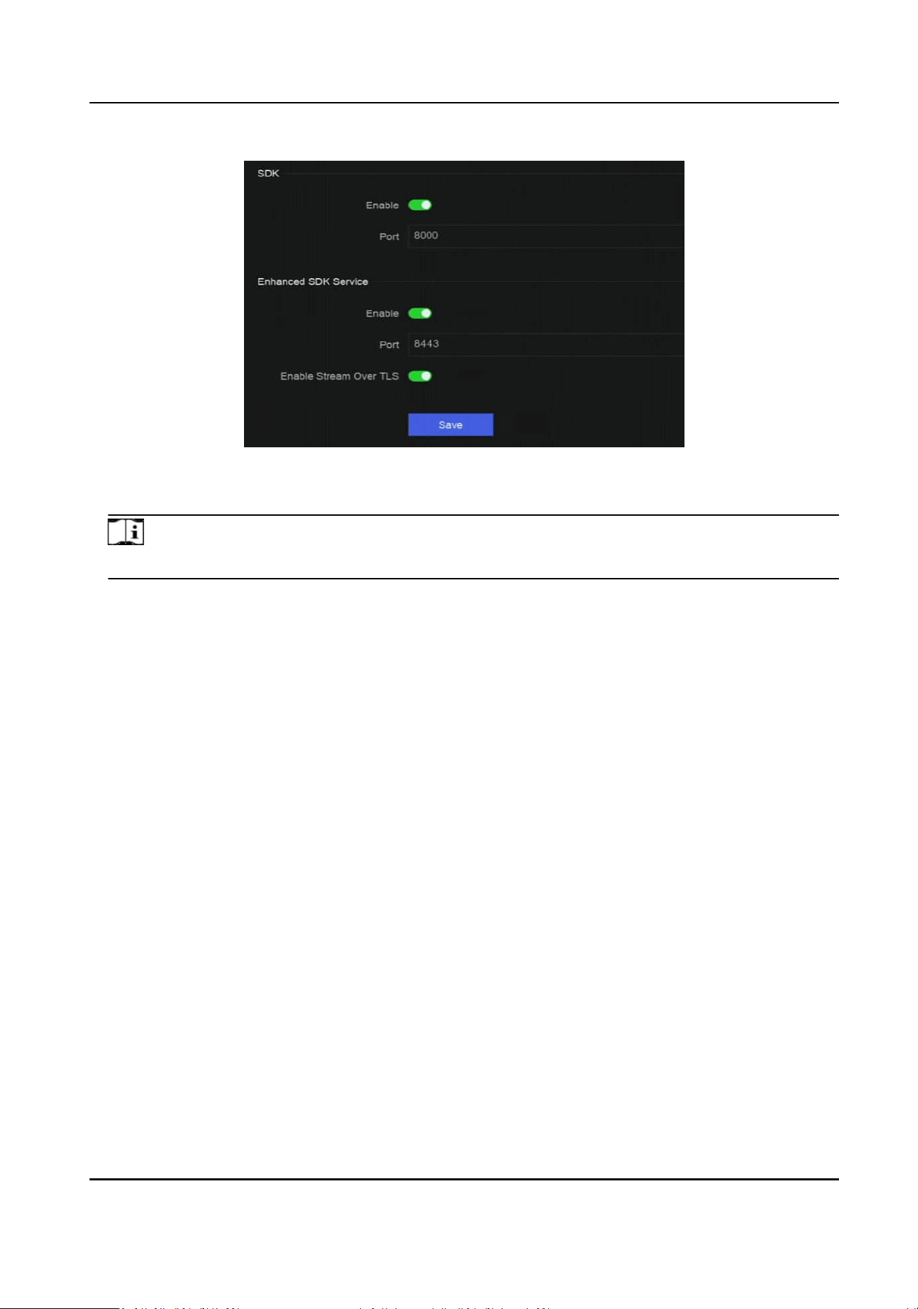
Figure 4-8 SDK Service
2.
Congure SDK and Enhanced SDK Service according to your requirement.
Note
The port for Enhanced SDK Service is 8443 by default.
3.
Oponal: Enable Stream Over TLS. The stream over TLS encrypon technology provides more
secure stream transmission service.
4.
Click Save.
4.2.5 Enable ISAPI
ISAPI (Internet Server Applicaon Programming Interface) is an open protocol based on HTTP,
which can realize the
communicaon between the system devices (e.g., network camera, NVR,
etc.).
Go to System → System
Sengs → Network → Plaorm Access → ISAPI to enable the funcon.
4.2.6
Congure ONVIF
ONVIF protocol allows the connecon with third-party cameras. The added user accounts have the
permission to connect other devices via ONVIF protocol.
Steps
1.
Go to System → CX → System
Sengs → Network → Plaorm Access → ONVIF .
Network Video Recorder User Manual
14
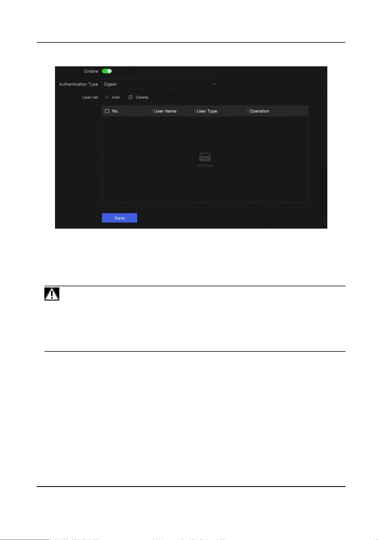
Figure 4-9 ONVIF
2.
Turn on Enable.
3.
Select an authencaon type.
4.
Click Add to add a user.
5.
Set the user name and password.
Cauon
We highly recommend you create a strong password of your own choosing (Using a minimum of
8 characters, including at least three of the following categories: upper case leers, lower case
leers, numbers, and special characters.) in order to increase the security of your product. And
we recommend you reset your password regularly, especially in the high security system,
reseng the password monthly or weekly can beer protect your product
6.
Click Save.
4.2.7
Congure Log Server
Logs can be uploaded to the log server for backup.
Steps
1.
Go to System → System Sengs → Network → Plaorm Access → Log Server.
Network Video Recorder User Manual
15

Figure 4-10 Log Server
2.
Turn on Enable.
3.
Set Upload Time Interval, Server IP Address, and Port.
4.
Oponal: Click Test to check if parameters are valid.
5.
Click Save.
4.3 Network Service
Sengs
4.3.1 Congure HTTP(S)
HTTP ((Hyper Text Transfer Protocol) and HTTPS (Hypertext Transfer Protocol Secure) ports are
used for remote access through web browser. HTTPS protocol enables encrypted transmission and
identy authencaon, which improves the security of remote access.
Steps
1.
Go to System → System Sengs → Network → Network Service → HTTP(S).
Network Video Recorder User Manual
16
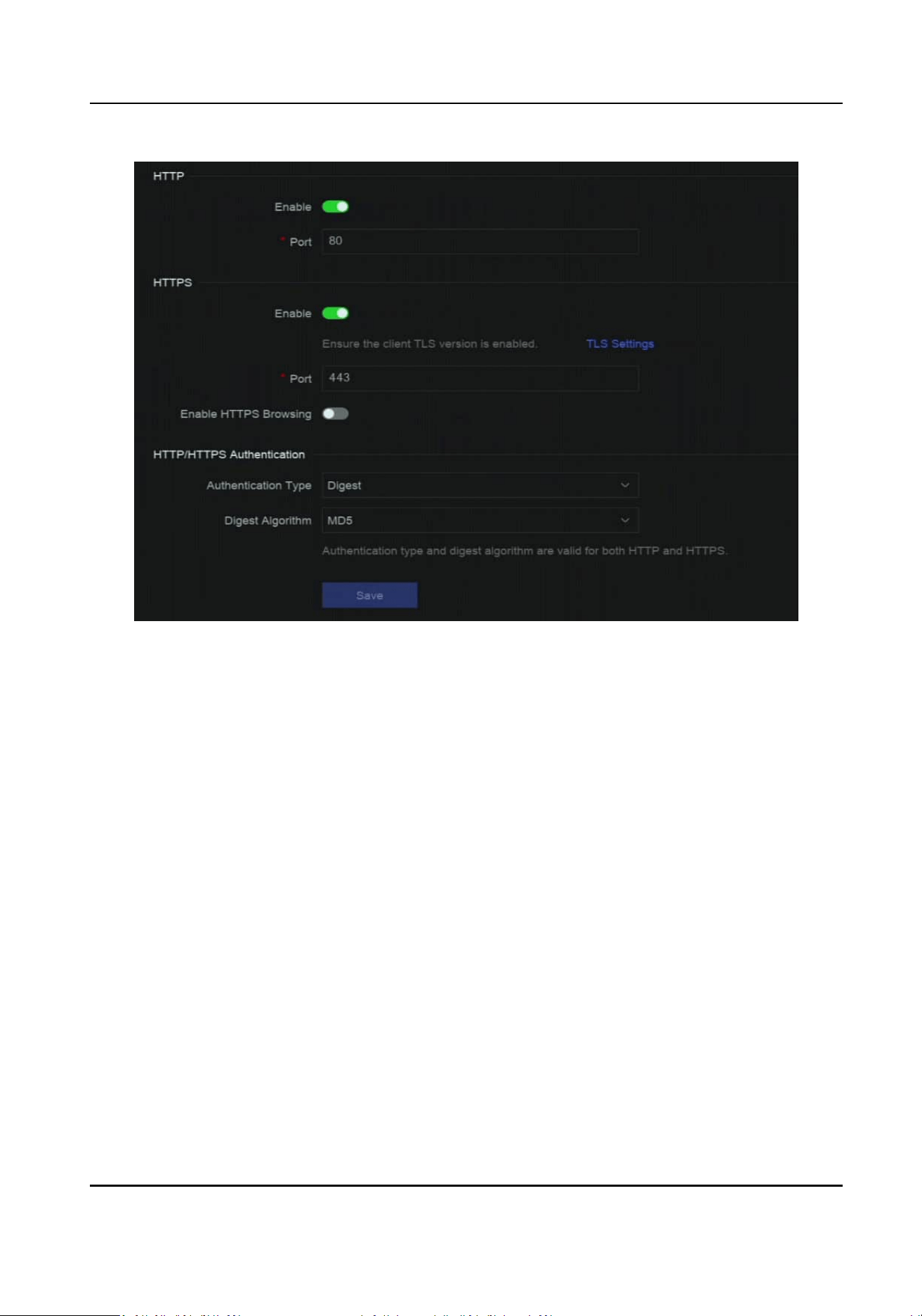
Figure 4-11 HTTP(S)
2.
Oponal: Turn on HTTP or HTTPS.
3.
View or edit Port of HTTP or HTTPS.
4.
Set HTTP/HTTPS
Authencaon.
Authencaon Type
Two authencaon types are selectable, for security reasons, it is recommended to select
Digest as the
authencaon type.
Digest Algorithm
Digest algorithms are based on HTTP/HTTPS and are mainly used for the digest
authencaon of user authencaon.
5.
Click Save.
4.3.2
Congure RTSP
RTSP (Real Time Streaming Protocol) is a network control protocol designed to control streaming
media servers. You can specically secure the stream data of live view by seng the RTSP
authencaon.
Steps
1.
Go to System → System
Sengs → Network → Network Service → RTSP .
Network Video Recorder User Manual
17

Figure 4-12 RTSP
2.
Set parameters.
Port
The port is 554 by default.
Authencaon Type
Two authencaon types are selectable, if you select Digest, only the request with digest
authencaon can access the video stream by RTSP via the IP address. For security reasons, it
is recommended to select Digest as the authencaon type.
RTSP Digest Algorithm
RTSP digest algorithm is based on RTSP, it is an algorithm for digest authencaon of the user
authencaon.
3.
Click Save.
4.3.3
Congure WebSocket(s)
WebSocket protocol, based on TCP, aims to provide full-duplex communicaon between web
browsers and servers. It allows to open a two-way interacve communicaon session.
Steps
1.
Go to System → System Sengs → Network → Network Service → WebSocket(s) .
2.
Turn on Enable.
3.
Set Port.
4.
Click Save.
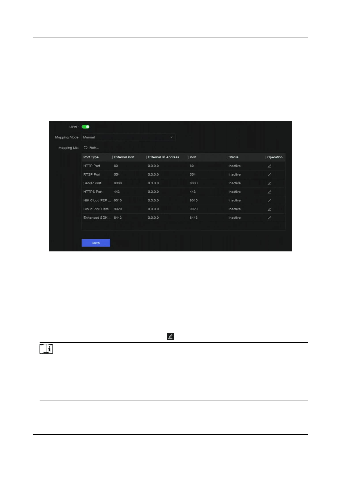
4.3.4
Congure Port Mapping (NAT)
Two ways are provided for port mapping to realize the remote access via the cross-segment
network, UPnP™ (Universal Plug and Play), and manual mapping. UPnP™ can permit the device
seamlessly discover the presence of other network devices on the network and establish
funconal
network services for data sharing, communicaons, etc. You can use the UPnP™ funcon to enable
the fast connecon of the device to the WAN via a router without port mapping.
Network Video Recorder User Manual
18
Before You Start
If you want to enable the UPnP™ funcon of the device, you must enable the UPnP™ funcon of
the router to which your device is connected. When the network working mode of the device is set
as
mul-address, the Default Route of the device should be in the same network segment as that
of the LAN IP address of the router.
Steps
1.
Go to System → System Sengs → Network → Network Service → NAT .
Figure 4-13 Port Mapping (NAT)
2.
Turn on Enable.
3.
Set Mapping Mode.
Auto
The port mapping items are read-only, and the external ports are set by the router
automacally.
Manual
You can manually edit the external port.
4.
If Mapping Mode is selected as Manual, click to edit corresponding ports.
Note
●
The value of the RTSP port number should be 554 or between 1024 and 65535, while the
value of the other ports should be between 1 and 65535 and the value must be dierent from
each other. If mulple devices are congured for the UPnP™ sengs under the same router,
the value of the port No. for each device should be unique.
●
External Port indicates the internal port number for port mapping in the router.
5.
Click Save.
Network Video Recorder User Manual
19

What to do next
Enter the virtual server sengs page of router, then ll in the blank of internal/external source
port with the internal/external port value, and other required contents.
4.3.5 Congure IoT
You can congure the network port through which the NVR will receive alarms from a security
control panel.
Go to System → System Sengs → Network → Network Service → IoT to enable the funcon and
congure the port number.
Note
The port number you congured here should be the same as the alarm sending port on the
security control panel.
Network Video Recorder User Manual
20
Chapter 5 User Management
There is a default account for administrator. The administrator user name is admin. Administrator
has the permission to add, delete, and edit user. Guest and operator users only have limited
permissions.
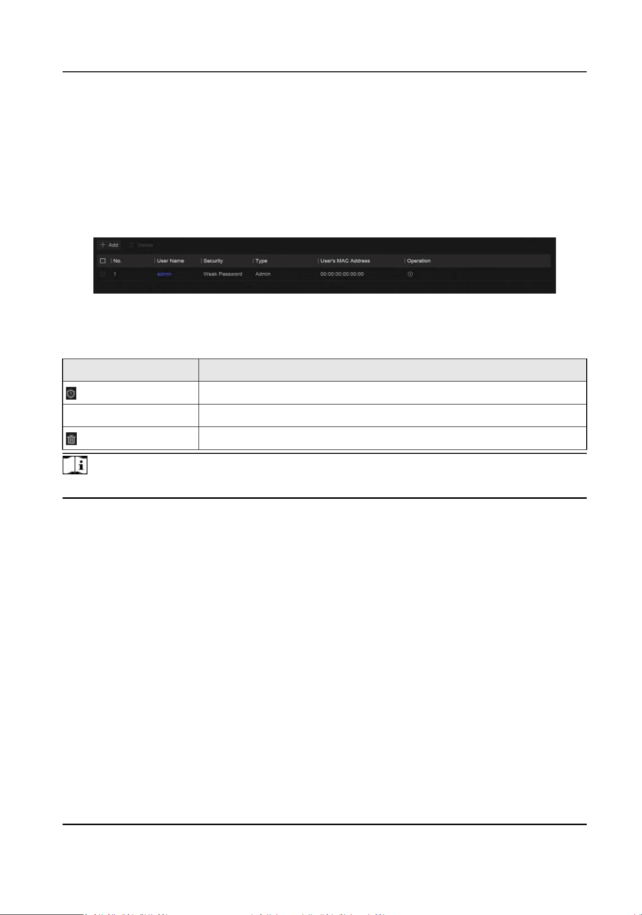
Go to System → System
Sengs → User Management .
Figure 5-1 User Management
Table 5-1 Icon/Buon Descripon
Icon/Buon Descripon
Set account security.
Add Add a new guest or operator user.
Delete the selected user.
Note
Before operaon, you have to conrm the admin password.
Network Video Recorder User Manual
21
Chapter 6 Device Access
The video recorder may be able to access mulple device types, such as network camera, access
control device, and alarm device. Please refer to the actual device for the access capability of your
video recorder.
6.1 Access Video Device
There are several ways to access a video device.
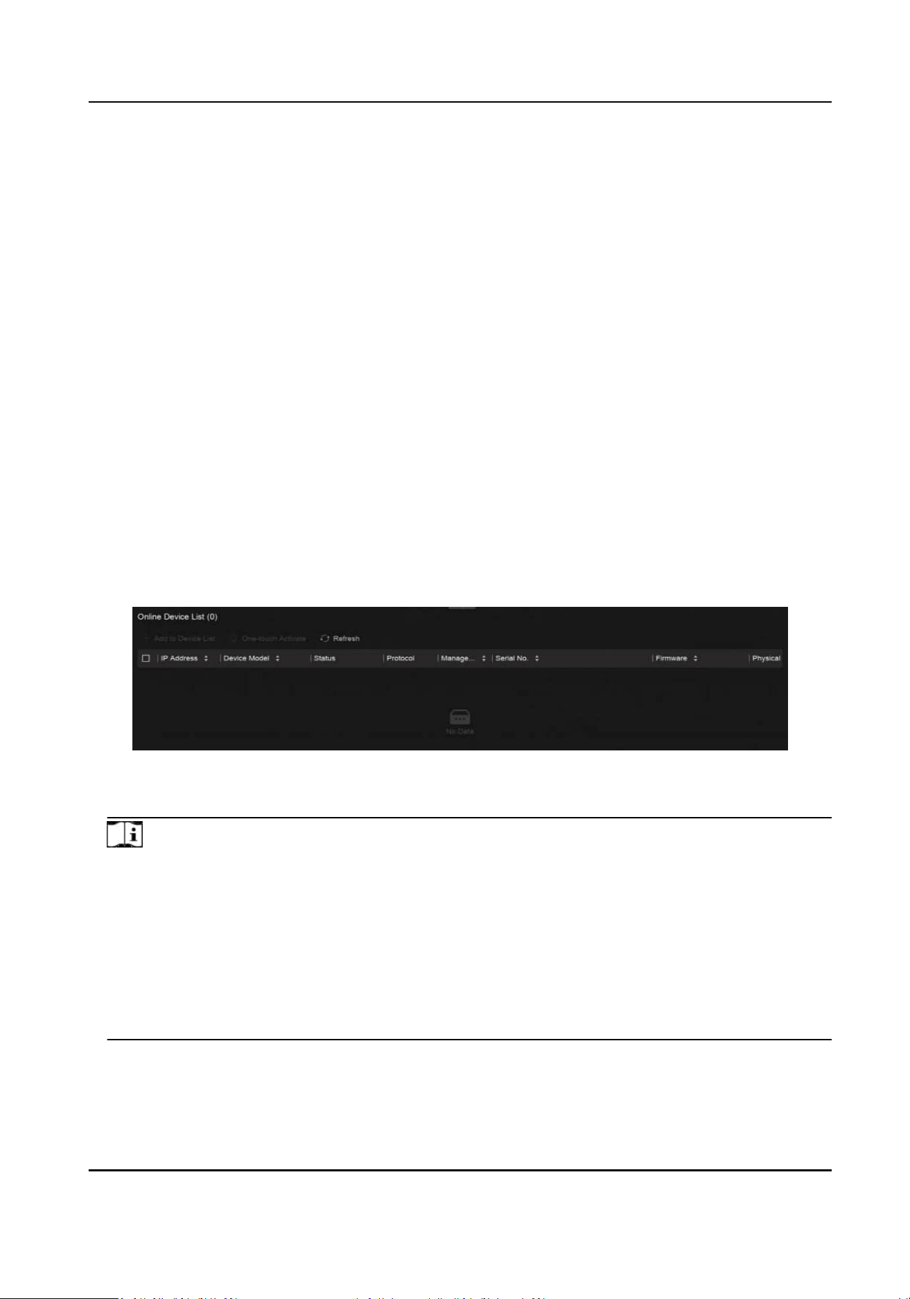
6.1.1 Add
Automacally Searched Online Network Camera
Network cameras on the same network segment can be automacally searched and added to the
device.
Steps
1.
Go to System → Device Access → Device → Video Device → Online Device List .
2.
Select the device(s) from the list.
Figure 6-1 Add Automacally Searched Online Network Camera
3.
Click Add to Device List.
Note
●
The device will use a default password to add network cameras, ensure the camera password
is the same as the default password. The default password can be congured in More →
Default Password Sengs.
●
If the searched network cameras are not
acvated, the device will use a default password to
acvate and add inacve network cameras. The default password can be congured in More
→ Default Password
Sengs.
●
When a network camera is successfully added, its status would be Online.
●
You can click the device name to add its parameters.
Network Video Recorder User Manual
22
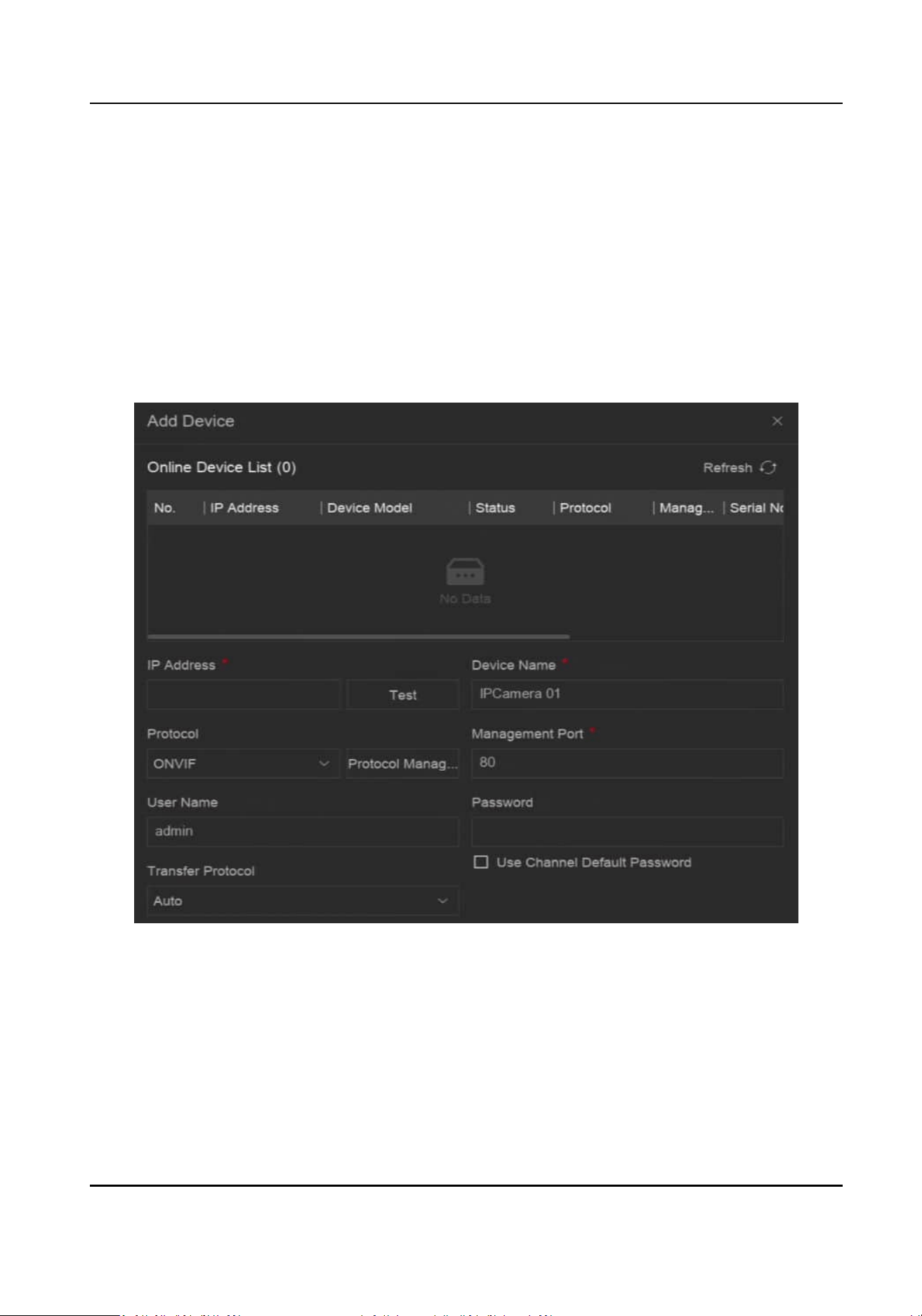
6.1.2 Add Network Camera Manually
Manually add the network cameras to your video recorder.
Before You Start
●
Ensure your network camera is on the same network segment with that of your video recorder.
●
Ensure the network
connecon is valid and correct.
●
Ensure the network camera is
acvated.
Steps
1.
Go to System → Device Access → Device → Video Device .
Figure 6-2 Add Network Camera Manually
2.
Click Add.
3.
Enter network camera parameters.
Use Channel Default Password
If it is enabled, the video recorder will add the camera by the set channel default password.
More Sengs
Network Video Recorder User Manual
23

You can enable Verify Cercate to verify the camera with cercate. The cercate is a form
of idencaon for the camera that provides more secure camera authencaon. It requires
to import the network camera cercate to the device rst when you use this funcon.
4.
Oponal: Click Connue to Add to add other network cameras.
5.
Click Add.
6.1.3 Add Network Camera through PoE
A PoE (Power over Ethernet) network camera can be directly connected to your device through the
PoE interface at the rear panel.
Aer using a network cable to connect a PoE network camera with your device, you shall congure
the corresponding PoE interface. Refer to Congure PoE (Power over Ethernet) Interface for
details.
6.1.4 Add Solar-Powered Camera through OTAP Protocol
Solar-powered cameras can be added to your device through OTAP protocol.
Before You Start
Ensure the network between your device and solar-powered camera is accessible through OTAP
protocol.
Enter the context of your task here
(oponal).
Steps
1.
Go to System → Device Access → Device
Conguraon → Access Service → OTAP Service.
2.
Turn on Enable.
3.
Set OTAP Server Port and
Encrypon Key.
4.
Oponal: Enable Auto Add IP Camera. Aer the device OTAP parameters are congured, the
newly signed network cameras (through OTAP protocol) can be automacally added to your
device.
5.
Congure the solar-powered camera OTAP protocol parameters through web browser. Refer to
the camera user manual for details.
Note
The solar-powered camera OTAP protocol parameters shall be the same as the device.
6.
Add solar-powered camera(s) to your device.
-
If you have enabled Auto Add IP Camera, the newly signed network cameras (through OTAP
protocol) would automacally be added to your device.
-
Select solar-powered camera(s) from Online Device List, and click Quick Add.
7.
Click Add in System → Device Access → Device → Video Device, select Protocol as OTAP, and
click Add.
Network Video Recorder User Manual
24
What to do next
●
Aer a solar-powered camera is add to your device, you can wake it up, view its baery power,
view its live video, congure its parameters through web browser, etc.
●
Set ANR
(Automac Network Replenishment) for the camera. Refer to Congure Recording
Schedule .
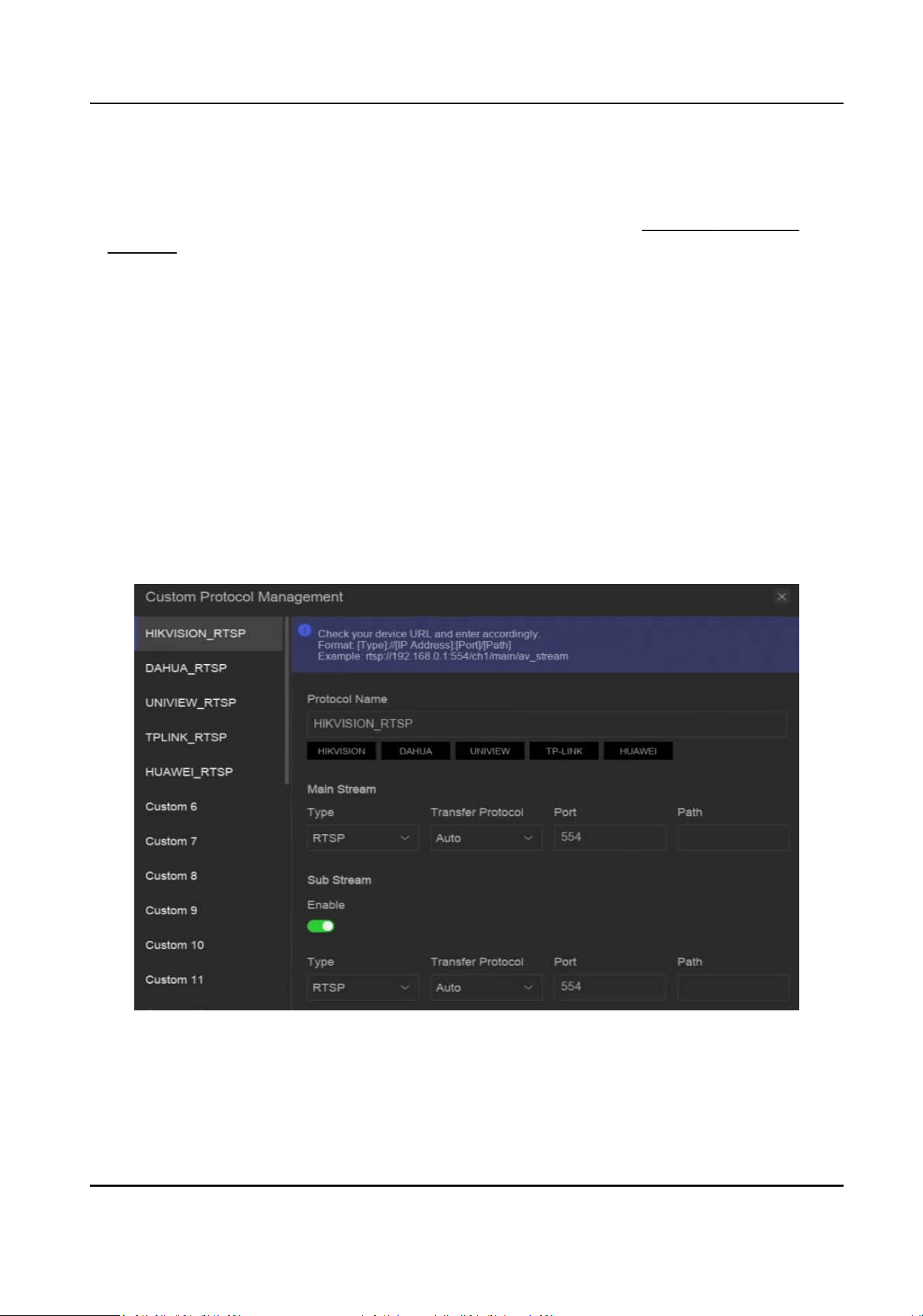
6.1.5 Add Network Camera via Custom Protocol
For network cameras that are not using standard protocols, you can congure custom protocols to
add them. The system provides 8 custom protocols.
Before You Start
●
Ensure the network camera supports RTSP streaming.
●
Prepare the URL (Uniform Resource Locator) for geng the main stream or sub-stream of
network cameras.
Steps
1.
Go to System → Device Access → Device → Video Device .
2.
Click More → Custom Protocol Management , or Add → Protocol Management .
Figure 6-3 Add Network Camera via Customized Protocol
3.
Select a protocol type at the le side.
4.
Set protocol parameters.
Network Video Recorder User Manual
25

Type
The network camera adopng custom protocol must support geng stream through
standard RTSP.
Transfer Protocol
3 types are selectable, including Auto, UDP, and RTP Over RTSP.
Port
The port for RTSP streaming, its default value is 554.
Path
Contact the manufacturer of network camera for the URL of
geng main stream and sub-
stream. The general format is [Type]://[IP Address]:[Port]/[Resource Path], for example,
rtsp://192.168.0.1:554/ch1/main/av_stream.
Note
●
Protocol Name and Path can be automacally generated if you click a brand name below
Protocol Name.
●
You can disable sub-stream if the camera does not support sub-stream or does not have to
use the sub-stream.
5.
Click OK.
6.
Click Add in System → Device Access → Device → Video Device to manually add a network
camera.
6.1.6 Add Network Camera through Camera
Conguraon File
The informaon of added network cameras can be exported, including the IP address, port,
password of admin, etc. And the exported camera
conguraon le content can be edited on your
computer. Aer eding, the le can also be imported to other devices to add the cameras in the
le.
Before You Start
Connect your video recorder to a USB
ash drive that contains camera conguraon le in it.
Steps
1.
Go to System → Device Access → Device → Video Device .
2.
Click Import to import the conguraon le in USB ash drive.
3.
Set the folder path.
4.
Click
Conrm.
6.2 Add Access Control Device
Access control devices can be added to your video recorder.
The adding process is similar with
Access Video Device .
Network Video Recorder User Manual
26

6.3 Add Security Control Panel
Steps
1.
Go to System → Device Access → Device → Security Control Panel .
2.
Click Add.
3.
Oponal: Select a protocol.
4.
Enter device IP address, name, and IoT service port.
5.
Oponal: Select a transfer protocol if you select OPTEX as the protocol type.
6.
Oponal: Click in the Operaon column to set OSD parameters including character encoding,
overlay mode, font size, etc.
Note
The Linked Channel cannot be edited. Go to Event Center → Event Conguraon → Event
Conguraon → Security Control Panel Event to edit the linked channel.
OSD informaon you have set will be displayed on the video image.
6.4 Add Audio Device
Audio devices can be added to your video recorder, such as IP speakers, and microphones.
The adding process is similar with
Access Video Device . If you link video channels with an IP
speaker, the IP speaker could be used for voice broadcast. If you link video channels with a
microphone, the microphone would be used as the audio input of the linked video channels for
video recording.
6.5 Add POS Device
POS machine/server can be connected for certain device models. The device can receive
transacon messages from POS machine/server, overlay transacon messages on the video image,
and trigger POS event alarms.
Steps
1.
Go to System → Device Access → Device → POS .
2.
Click Add to add a POS device.
Network Video Recorder User Manual
27
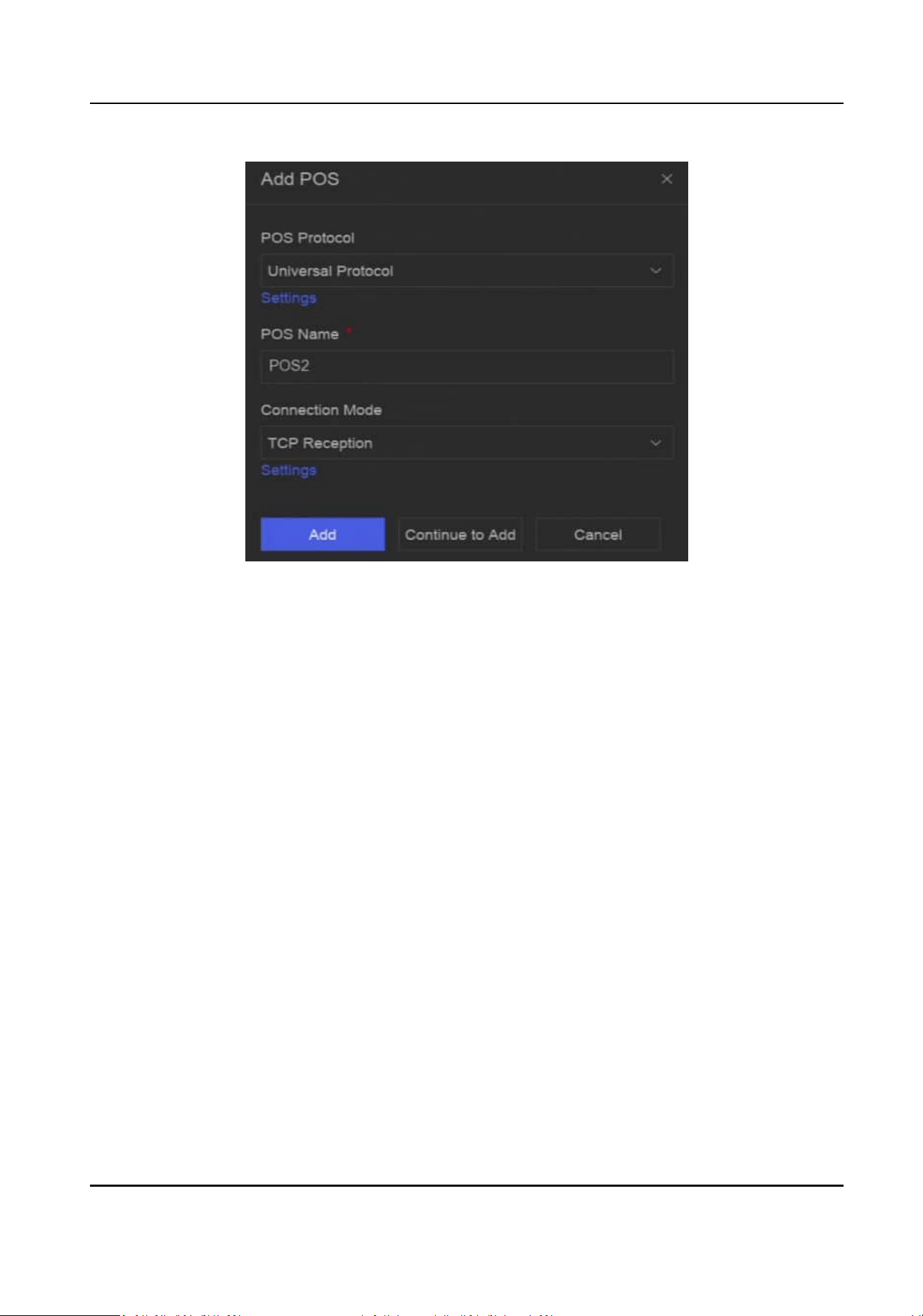
Figure 6-4 Add POS Device
3.
Set the POS device parameters.
POS Protocol
Universal Protocol
You can set the start line
idener, line break tag, and end line tag for the POS overlay
characters, and the case-sensive property of the characters. You can also oponally check
the ltering idener and the XML protocol.
EPSON
The
xed start and end line tag are used for EPSON protocol.
AVE
The xed start and end line tag are used for AVE protocol. Serial port and virtual serial port
connecon types are supported.
NUCLEUS
The xed start and end line tag are used for AVE protocol. Serial port and virtual serial port
connecon types are supported. The NUCLEUS protocol must be used in the RS-232
connecon communicaon.
Connecon Mode
TCP Connecon
When using TCP connecon, the port must be set from 1 to 65535, and the port for each
POS machine must be unique.
Network Video Recorder User Manual
28

UDP Connecon
When using UDP connecon, the port must be set from 1 to 65535, and the port for each
POS machine must be unique.
USB-to-RS-232 Connecon
Congure the USB-to-RS-232 convertor port parameters, including the port serial number,
baud rate, data bit, stop bit, and parity.
RS-232 Connecon
Connect the device and the POS machine via RS-232.
Mulcast Connecon
When connecng the device and the POS machine via Mulcast protocol, set the mulcast
address and port.
Sni Connecon
Connect the device and the POS machine via Sni. Congure the source address and
desnaon address sengs.
4.
Click Add.
Note
Aer a POS device is add, you can click in Operaon to congure POS text overlay.
6.6 Channel Management
Aer a video device is added, you can view its channel number and channel name, and manage its
parameters. This funcon is mainly used for a video device that contains more than one channel.
Go to System → Device Access → Channel to manage channels of video devices.
Network Video Recorder User Manual
29
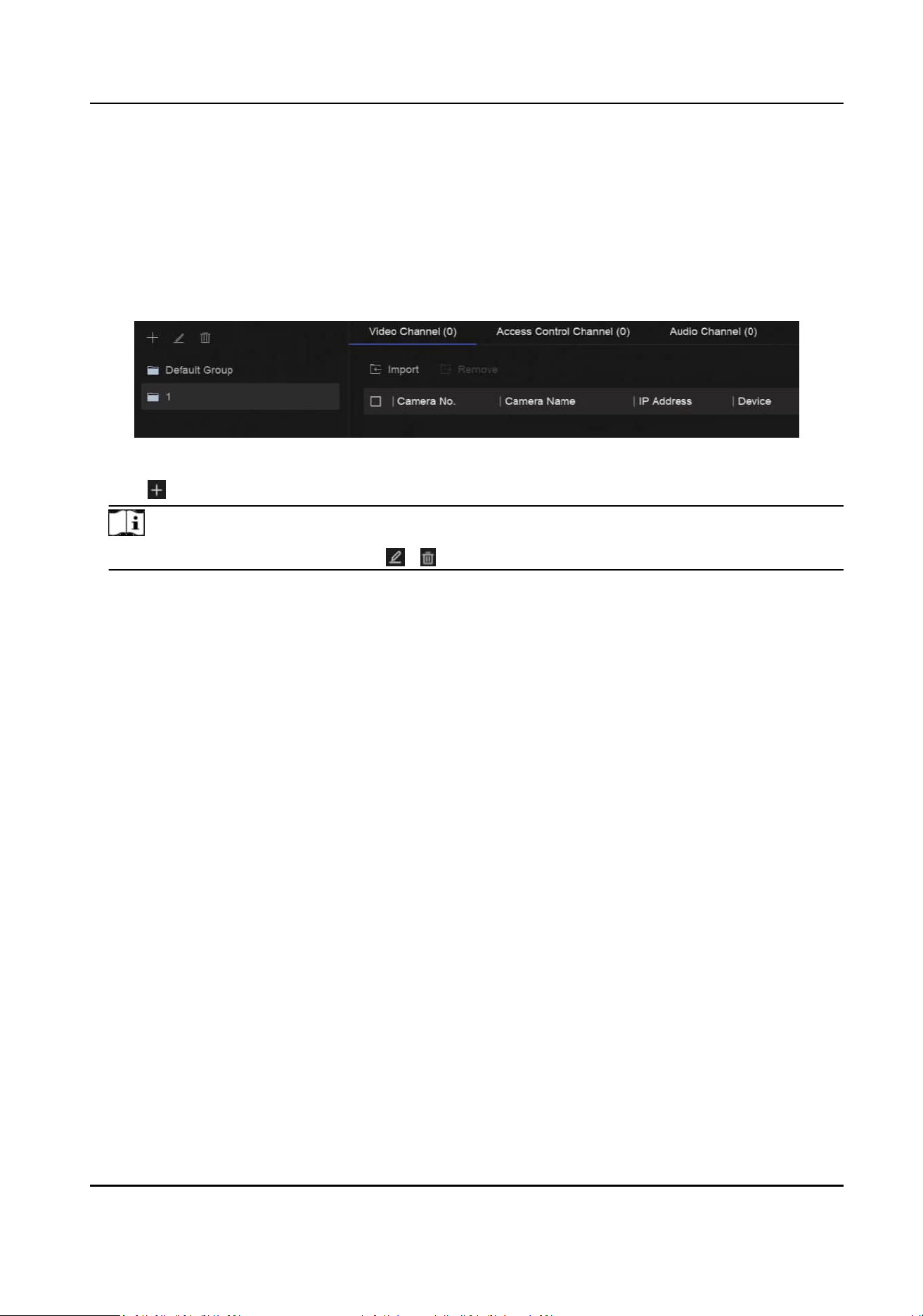
Chapter 7 Device Grouping
The added devices can be classied into dierent customized groups.
Steps
1.
Go to System → Device Access → Device Grouping .
Figure 7-1 Device Grouping
2.
Click to add a group.
Note
Aer a group is added, you can click / to edit/delete it.
3.
Click Import to add channel(s) to the selected group.
Network Video Recorder User Manual
30

Chapter 8 Video or Audio Device Sengs
You can congure the added video or audio device, such as privacy mask, image parameters, etc.
8.1 Enable H.265 Stream Access
The device can automacally switch to the H.265 stream of IP camera (which supports H.265 video
format) for the
inial access.
Steps
1.
Go to System → Device Access → Device → Video Device .
2.
Click More → Auto Switch to H.265 .
3.
Enable this
funcon.
4.
Click Save.
8.2
Congure Display Sengs
Congure the OSD (On-Screen Display), image sengs, exposure sengs, day/night switch
sengs, etc.
Go to System → Device Access → Device Conguraon → Device Parameter → Video Device →
Display
Sengs. Select a camera, and congure parameters as your desire.
OSD Sengs
Congure the OSD (On-screen Display) sengs for the camera, including date/me, camera
name, etc.
Image
Sengs
Customize the image parameters including the brightness, contrast, and saturaon for the live
view and recording eect.
Exposure Time
Set the camera exposure me (1/10000 to 1 sec). A larger exposure value results in a brighter
image.
Day/Night Switch
The camera can be set to day, night, or auto switch mode according to the surrounding
illuminaon condions.
Backlight
Set the camera's wide dynamic range (0 to 100). When the surrounding illuminaon and the
object have large
dierences in brightness, you should set the WDR value.
Image Enhancement
Network Video Recorder User Manual
31

For opmized image contrast enhancement.
8.3 Congure Video Parameters
Video parameters would aect the live view image and recording le.
Go to System → Device Access → Device Conguraon → Device Parameter → Video Device →
Video Parameters. Select a camera, and congure parameters as your desire.
Main Stream
Main stream refers to the primary stream that aects data recorded to the hard disk drive and
will directly determine your video quality and image size. Comparing with the sub-stream, the
main stream provides a higher quality video with higher
resoluon and frame rate.
Sub-Stream
Sub-stream is a second codec that runs alongside the mainstream. It allows you to reduce the
outgoing internet bandwidth without sacricing your direct recording quality. Sub-stream is
oen exclusively used by smartphone applicaons to view live video. Users with limited internet
speeds may benet most from this seng.
Resoluon
Image resoluon is a measure of how much detail a digital image can hold. The greater the
resoluon, the greater the level of detail. Resoluon can be specied as the number of pixel-
columns (width) by the number of pixel-rows (height), e.g., 1024 × 768.
Bitrate Type
The bit rate (in kbit/s or Mbit/s) is
oen referred to as speed, but actually denes the number of
bits/me unit rather than distance/me unit. Two types including variable or constant are
available.
Frame Rate
It refers to the number of frames captured each second. A higher frame rate is advantageous
when there is movement in the video stream, as it maintains image quality throughout.
I-Frame Interval
I-Frame also referred as intra picture, I-Frame is the
rst frame of every GOP (a video
compression technology of MPEG). It can be viewed as pictures aer compression. I-Frame
interval is the amount of frames between two connuous I-Frames.
8.4
Congure Privacy Mask
The privacy mask protects personal privacy by concealing parts of the image from live view or
recording with a masked area.
Network Video Recorder User Manual
32

Steps
1.
Go to System → Device Access → Device Conguraon → Device Parameter → Video Device →
Privacy Mask.
Figure 8-1 Privacy Mask
2.
Select a camera.
3.
Turn on Enable.
4.
Draw mask areas on the preview window. The areas will be marked with dierent frame colors.
Note
Up to 4 privacy mask areas can be congured and the size of each area can be adjusted.
5.
Click Save.
8.5
Congure Privacy Protecon
This funcon allows for the automac obscuring or blurring of specic areas (including human
faces, human bodies, and vehicles) on the video footage to protect personal privacy or sensive
informaon.
Before You Start
This funcon should be supported by the camera.
Network Video Recorder User Manual
33
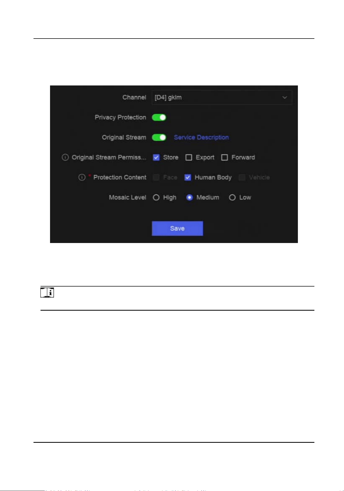
Steps
1.
Go to System → Device Access → Device Conguraon → Device Parameter → Video Device →
Privacy Protecon .
Figure 8-2 Privacy Protecon
2.
Select a camera.
3.
Enable Privacy Protecon.
4.
Oponal: Enable Original Stream and set the stream permission.
Note
Original stream means the video stream without mosaic.
Store
The original stream can be stored. Storing original stream will cost more storage space or
decrease the recording storage period of the channel. The original stream bitrate is the same
as the camera, which is not
congurable.
Export
The channel original stream can be exported.
Forward
The original stream can be forwarded.
Network Video Recorder User Manual
34
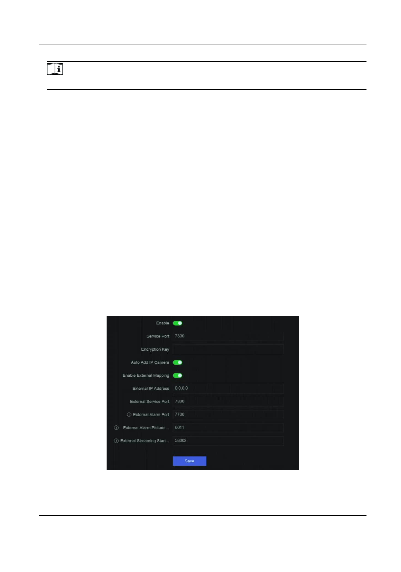
Note
You should check Store permission before checking Export and/or Forward permissions.
5.
Set Protecon Content. The selected protecon content will be blurred during live view and
playback.
6.
Set Mosaic Level. Higher the level, more blurred the target image.
7.
Click Save.
8.6 Congure Audio Parameter
Aer an audio device is added, you can congure its parameters in System → Device Access →
Device
Conguraon → Device Parameter → Audio Device. For example, if an IP speaker is added,
its name, audio output volume and audio quality can be congured.
8.7
Congure OTAP Service
OTAP (Open Thing Access Protocol) is an unied integrated standard and push-pull mode of
Hikvision protocol in the public network and private network.
Aer OTAP is enabled, other
applicaons may be able to remotely view videos through this protocol.
Before You Start
Ensure your device network is accessible through OTAP protocol.
Steps
1.
Go to System → Device Access → Device Conguraon → Access Service → OTAP Service.
Figure 8-3 Congure OTAP Service
Network Video Recorder User Manual
35
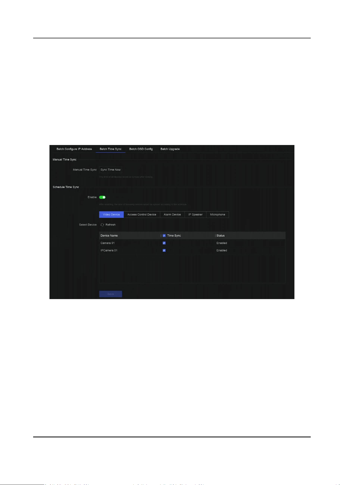
2.
Turn on Enable.
3.
Set the parameters.
4.
Click Save.
8.8 Batch Conguraon
Connected devices can be congured in a batch.
Steps
1.
Go to System → Device Access → Device Conguraon → Batch Conguraon .
Figure 8-4 Batch Conguraon
2.
Congure IP address, me sync, OSD, or upgrade rmware as your desire.
Manual Time Sync
Click Sync Time Now to manually sync me of all connected devices. This operaon is just for
once.
Schedule Time Sync
The recorder would sync
me of the selected devices according a xed schedule.
3.
For IP address conguraon and me sync, click Save.
Network Video Recorder User Manual
36

8.9 Congure PoE (Power over Ethernet) Interface
The PoE interfaces enable the device to transfer electrical power and data to connected PoE
devices. And the PoE interface supports the Plug-and-Play funcon. Connectable PoE device
number varies with device models. If you disable a PoE interface, you can also use it to connect to
an online device.
Before You Start
Ensure your NVR support PoE
funcon.
Steps
1.
Go to System → Device Access → Device
Conguraon → PoE.
2.
Enable Plug-and-Play funcon of PoE interfaces according to your requirement.
3.
Select the device type as IP Speaker or Camera.
4.
If a PoE interface is used to connect a PoE camera, select the
connecon distance of network
cable.
Long Distance
Long-distance (100 to 300 meters) network transmissions via PoE interface.
Short Distance
Short-distance (< 100 meters) network transmission via PoE interface.
Note
●
The PoE interfaces are enabled with the short distance mode by default.
●
The bandwidth of IP camera connected to the PoE via long network cable (100 to 300 meters)
cannot exceed 6 MP.
●
The allowed max. long network cable may be less than 300 meters depending on
dierent IP
camera models and cable materials.
●
When the transmission distance reaches 100 to 250 meters, you must use the CAT5E or CAT6
network cable to connect with the PoE interface.
●
When the transmission distance reaches 250 to 300 meters, you must use the CAT6 network
cable to connect with the PoE interface.
5.
Click Save.
What to do next
When PoE devices are connected, you can view the status and power of each PoE interface.
Network Video Recorder User Manual
37

Chapter 9 Storage Management
9.1 Manage HDD
A newly installed hard disk drive (HDD) must be inialized before using. You can format HDD, repair
database, and view HDD status through HDD management interface.
Before You Start
Ensure the HDD is properly installed to your device.
Steps
1.
Go to System → Storage Management → Storage HDD → Storage HDD .
Figure 9-1 Manage HDD
2.
Oponal: Perform the following operaons as your desire.
Add Network
HDD
Add a NAS or IP SAN.
Format Format the selected HDD.
Repair
Database
Repairing database will rebuild all databases. It might help to improve your
system speed aer upgrade.
Note
●
Repairing database will rebuild all databases. Exisng data will not be
aected, but local search and playback funcons will not be available
during the process, you can sll achieve search and playback funcons
remotely via web browser, client soware, etc.
●
Do not pull out the drive, or shut down the device during the process.
/ Remove/load HDD.
9.2 RAID Conguraon
A disk array is a data storage virtualizaon technology that combines mulple physical disk drives
into a single logical unit. Also known as a "RAID", an array stores data over
mulple HDDs to
provide enough redundancy so that data can be recovered if one disk fails. Data is distributed
Network Video Recorder User Manual
38

across the drives in one of several ways called "RAID levels", based the redundancy and
performance required.
Cauon
RAID requires enterprise-level HDDs.
The funcons in this secon are only available for certain models. It is recommended to use the
same model and capacity HDDs.
There are two ways to create RAID. For one-touch creaon, the default RAID type is RAID5. For
manual
creaon, RAID0, RAID1, RAID5, RAID6, and RAID10 can be congured.
Table 9-1 HDD Requirement for Each RAID Type
RAID Type Required Number of HDDs
RAID0 ≥2
RAID1 2
RAID5 ≥3
RAID6 ≥4
RAID10 4 or 8
Note
●
The funcon is only available for certain models.
●
When array excepon event occurs, the corresponding linkage acons can be congured in
System → System Sengs → Excepon .
9.2.1 Create Disk Array
A disk array can be created aer enabling array mode.
Before You Start
●
Storage Mode is set to Quota in System → Storage Management → Storage Mode .
●
Enough HDDs are correctly installed to the device. And HDDs for array
creaon are AI or
enterprise level.
Steps
1.
Go to System → Storage Management → Storage HDD → Array Management .
2.
Click Enable Array Mode, or enable Array Mode.
Network Video Recorder User Manual
39
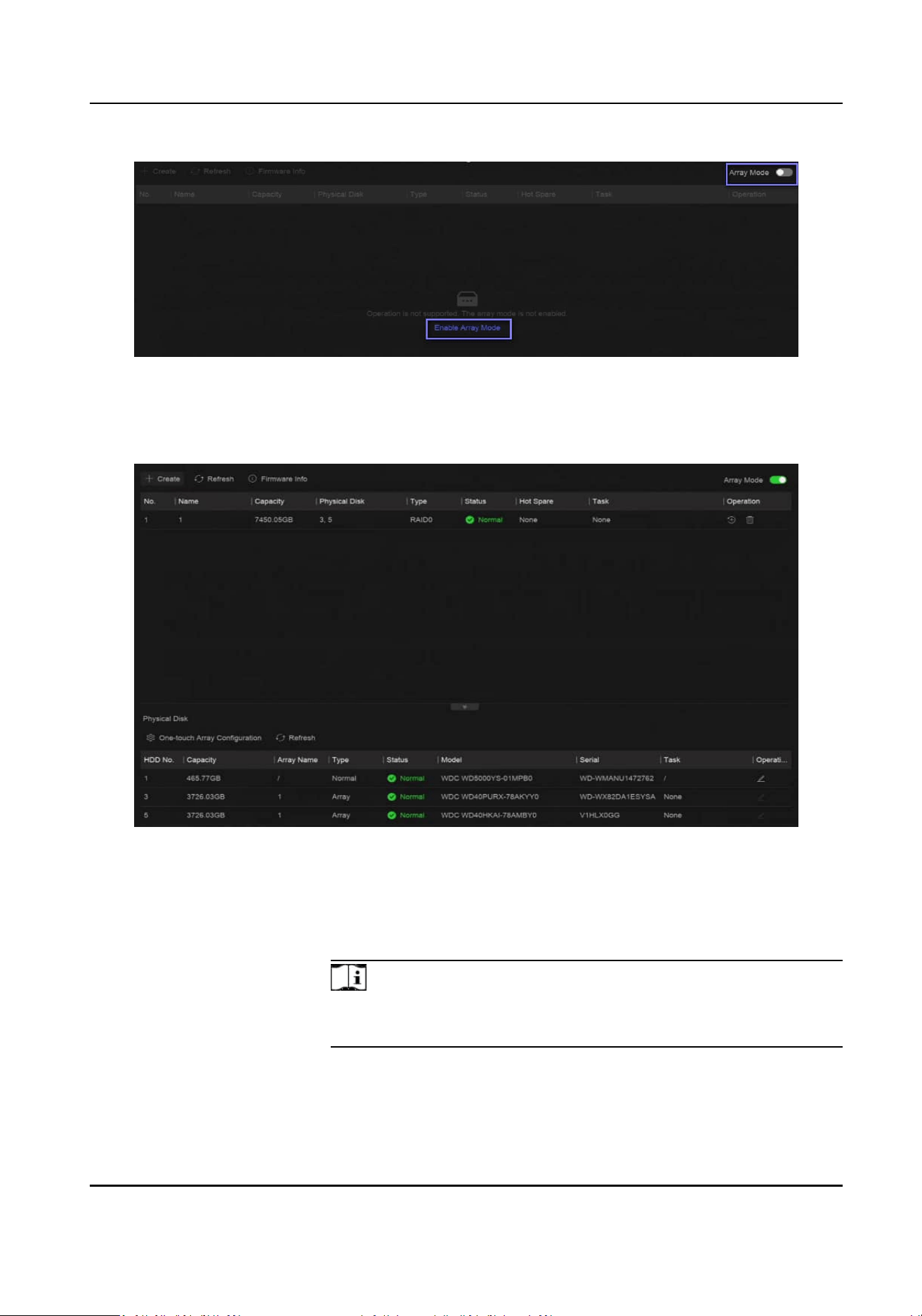
Figure 9-2 Enable RAID
3.
Wait for the device to restart.
4.
Go to System → Storage Management → Storage HDD → Array Management again.
Figure 9-3 Array Management
5.
Create an array.
Creaon
Method Descripon
One-touch Array
Conguraon
Click One-touch Array Conguraon.
Note
By default, the array type created by one-touch conguraon is
RAID 5.
Manual Creaon Click Create to manually create a RAID 0, RAID 1, RAID 5, RAID 6, or
RAID 10 array.
Network Video Recorder User Manual
40

9.2.2 Rebuild Array
The array status includes Funconal, Degraded, and Oine. To ensure the high security and
reliability of the data stored in an array, take immediate and proper maintenance of the arrays
according its status.
Steps
1.
Go to System → Storage Management → Storage HDD → Array Management .
2.
Rebuild an array.
Table 9-2 Rebuilding Method
Rebuilding Method Descripon
Auto Rebuild There should be a hot spare disk in the array,
and the hot spare disk capacity is not less than
the disk with the minimum capacity in the
array. Click
in Operaon column under
Physical Disk to set a hot spare disk.
When an HDD in the array in the array is not
working, the hot spare disk would be
acvated, and the array would be
automacally rebuilt.
Note
Aer auto rebuild nishes, it is recommended
to install another HDD, and congure it as the
hot spare disk.
Manual Rebuild If there is no hot spare disks in the array, you
have to manually rebuild the array.
Go to System → Storage Management →
Storage HDD → Array Management , and
select the hot spare disk in the list to rebuild.
9.2.3 Delete Array
Go to System → Storage Management → Storage HDD to click to delete the selected array.
9.2.4 View Firmware Info
You can view array rmware informaon and set the background task speed.
Network Video Recorder User Manual
41

Before You Start
Ensure disk array is enabled.
Steps
1.
Go to System → Storage Management → Storage HDD → Array Management .
2.
Click Firmware Info.
3.
Oponal: Set Back Ground Task Speed.
9.3 Congure Storage Mode
Steps
1.
Go to System → Storage Management → Storage Mode .
Figure 9-4 Storage Mode
2.
Select Quota or Group.
Quota
Each camera or audio device can be
congured with an allocated quota for storing videos,
pictures, or audios.
Group
Mulple HDDs can be managed in groups. Video from specied channels can be recorded
onto a
parcular HDD group through HDD sengs.
3.
Set corresponding parameters.
●
Quota: Allocate space for storage objects.
●
Group: Link channels to HDD groups.
9.4
Congure Other Storage Parameters
Go to System → Storage Management → Advanced Sengs .
Network Video Recorder User Manual
42

Table 9-3 Parameter Descripon
Parameter Name Descripon
HDD Sleeping Select a mode for HDDs. Performance Mode, Balanced Mode, and
Energy Saving Mode are selectable.
Overwring When HDD is full, it will connue to write new les by deleng the
oldest les.
Save Camera VCA Data Aer saving VCA data of camera to your device, you will be able to
search it in Event Center.
Max. Length per Video It is the me length of each video le when you exporng videos from
the device.
Tag Video Post-Record Aer adding a tag to a video, it is the me you set to record aer the
scheduled me.
Note
●
You can click during live view or playback to add a tag.
●
For searching tag videos, go to → Backup → By Tag.
eSATA For devices with eSATA interface at the rear panel.
Usage Set the usage for eSATA.
9.5 Mange USB Flash Drive
Aer inserng a USB ash drive in to your device, you can view its remaining storage capacity,
manage its content, or format it.
When a USB
ash drive is connected to your device for the rst me, short operaons can be
performed, such as device upgrade and backup. Meanwhile, there would be a new icon
displayed at the upper-right corner.
Network Video Recorder User Manual
43
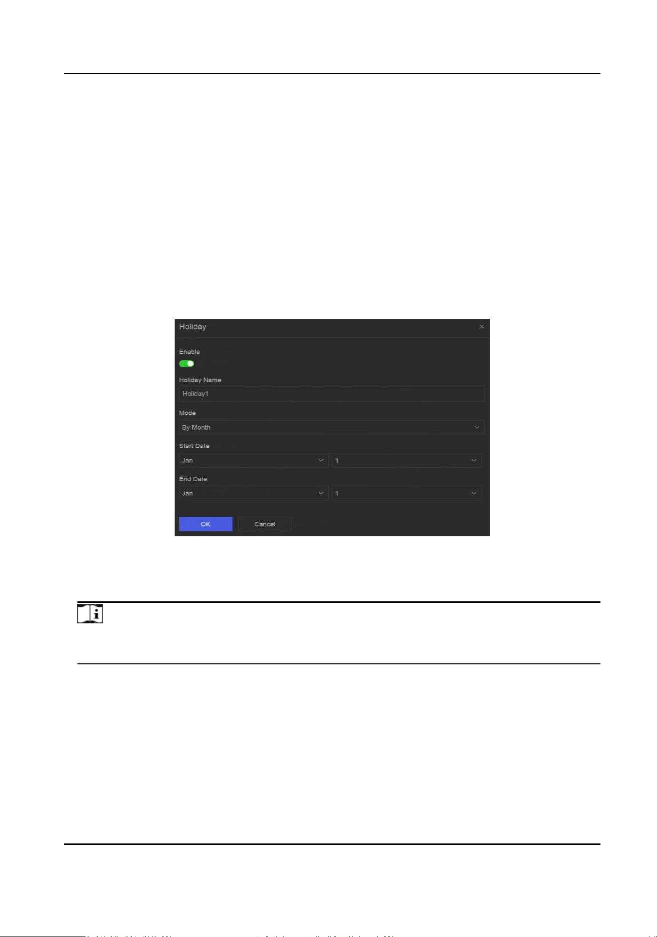
Chapter 10 Schedule Conguraon
The device will follow the schedule to store les to the disk.
10.1 Congure Schedule Template
Aer a schedule template is congured, you can use the template as the recording schedule.
Steps
1.
Go to System → System Sengs → Template Conguraon → Holiday Schedule .
2.
Click Add.
Figure 10-1 Add Holiday
3.
Turn on Enable.
4.
Congure the holiday.
Note
Aer holidays are congured, you will be able to set the holiday schedule independently.
Holiday schedule has higher priority than normal schedule (from Mon to Sun).
5.
Set Storage Schedule.
1) Click Storage Schedule.
2) Select a template name.
Network Video Recorder User Manual
44
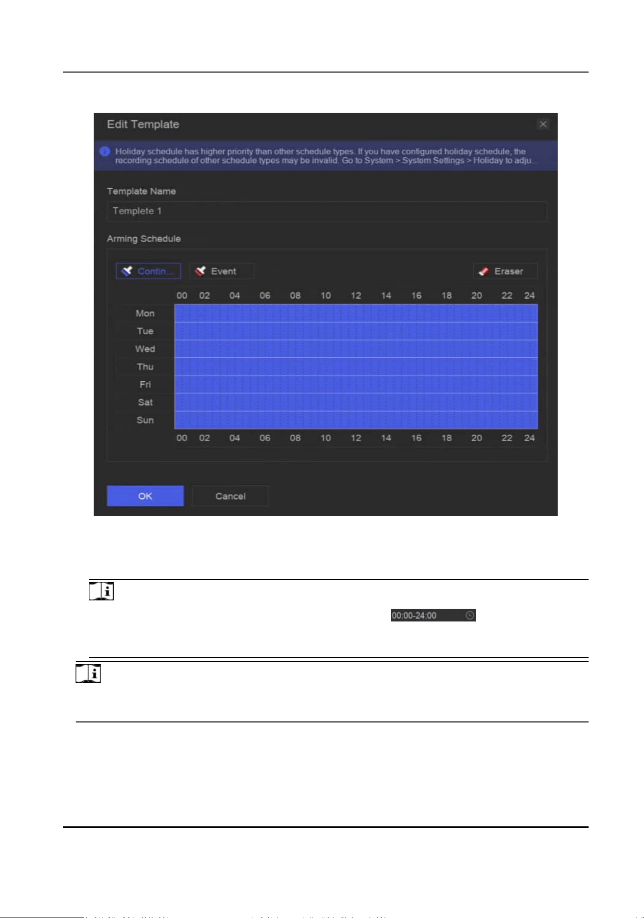
Figure 10-2 Edit Template
3) Select a recording type. For example, Event.
4) Drag the cursor on me bar to draw the schedule.
Note
●
Aer moving the cursor on me bar, you can also click to set specied me
schedule.
●
You can click Eraser to clear schedule.
Note
You can also click Congure Template to congure template in System → Storage Management
→ Storage Schedule → Video Recording / Picture Capture / Audio Recording .
6.
Click OK.
Network Video Recorder User Manual
45
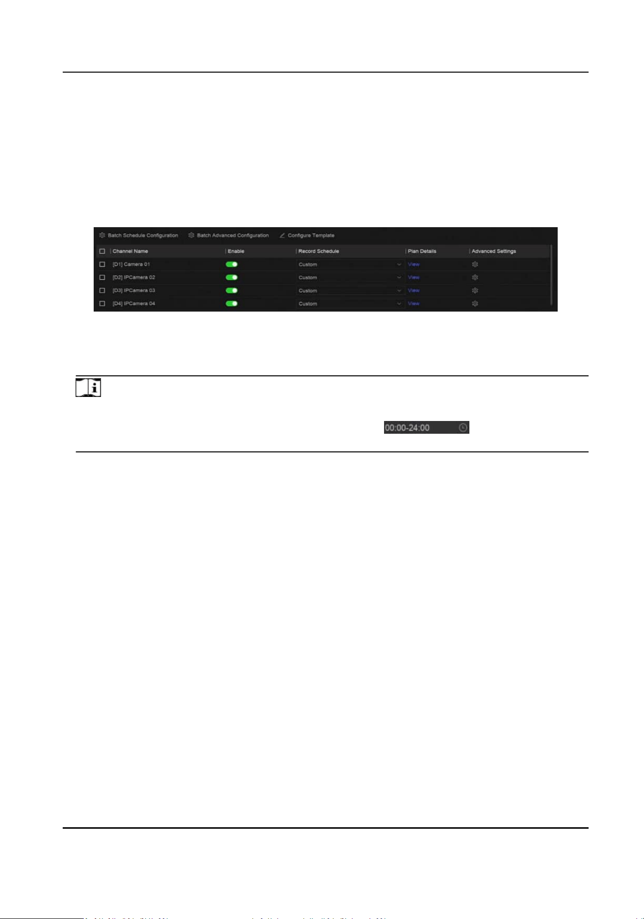
10.2 Congure Recording Schedule
The camera would automacally start/stop recording according to the congured recording
schedule.
Steps
1.
Go to System → Storage Management → Storage Schedule → Video Recording .
Figure 10-3 Video Recording Conguraon
2.
Turn on Enable for a camera.
3.
Select a schedule type.
Note
If you set Record Schedule as Custom, you can drag the cursor on me bar to set customized
record schedule, or move the cursor on me bar and click to set specied me
schedule.
4.
Click View to view the schedule.
Network Video Recorder User Manual
46
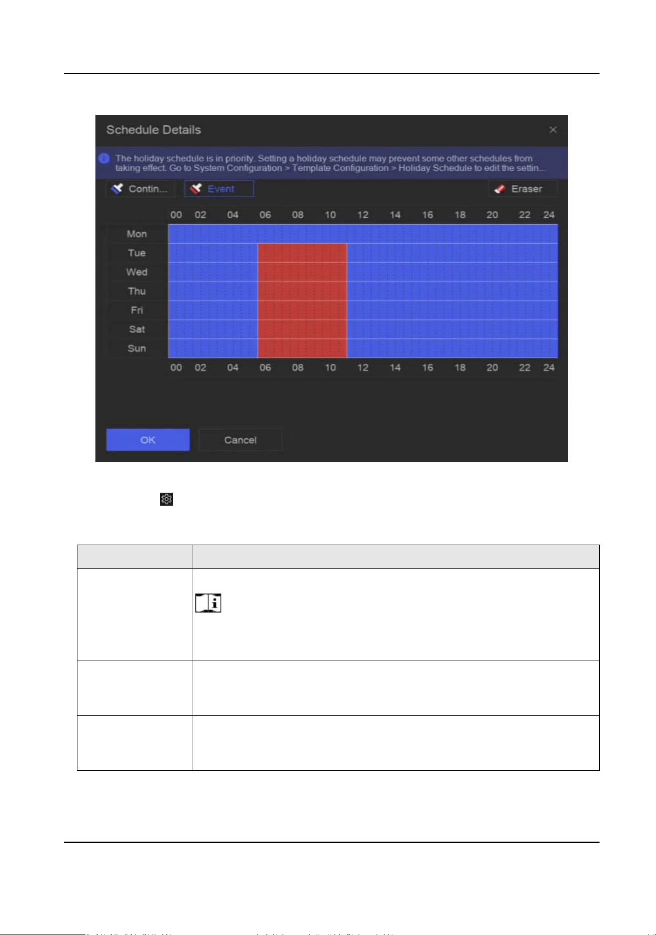
Figure 10-4 View Schedule
5.
Oponal: Click under Advanced Sengs to set other advanced parameters.
Table 10-1 Advanced Parameter
Descripon
Parameter Descripon
Record Audio Enable or disable audio recording.
Note
The channel shall have audio funcon, or have connected an audio
device.
ANR ANR (Automac Network Replenishment) can automacally enable SD
card of network camera to save the video in the condion of network
disconnecon, and can synchronize data aer the network is recovered.
Pre-Record The me you set to record before the scheduled me or event. For
example, when an alarm triggers the recording at 10:00, and if you set the
pre-record me as 5 seconds, the camera records at 9:59:55.
Network Video Recorder User Manual
47
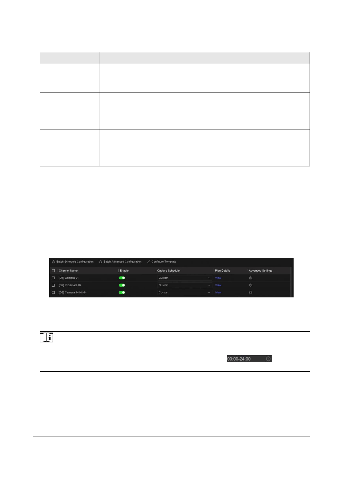
Parameter Descripon
Post-Record The me you set to record aer the event or the scheduled me. For
example, when an alarm triggered recording ends at 11:00, and if you set
the post-record me as 5 seconds, it records ll 11:00:05.
Stream Type For Main Stream, its resoluon is usually higher. For Sub-Stream, you can
record for a longer me with the same storage space, but its resoluon
would be low. For Dual Stream, the device will record both main stream
and sub-stream.
Video/Picture
Expired Time
The expired me is period for a le to be kept in the HDD. When the
deadline is reached, the le will be deleted. If you set the expired me to
0, the le will not be deleted. The actual keeping me for the le should
be determined by the capacity of the HDD.
6.
Oponal: Select channels in the list, and use Batch Schedule Conguraon and Batch Advanced
Sengs to congure channels in a batch.
7.
Click Save.
10.3
Congure Picture Capture Schedule
The device would automacally capture live pictures according to the schedule.
Steps
1.
Go to System → Storage Management → Storage Schedule → Picture Capture .
Figure 10-5 Picture Capture Conguraon
2.
Turn on Enable for a camera.
3.
Select a schedule type.
Note
If you set Capture Schedule as Custom, you can drag the cursor on me bar to set customized
picture capture schedule, or move the cursor on me bar and click to set
specied me schedule.
4.
Click View to view the schedule.
Network Video Recorder User Manual
48
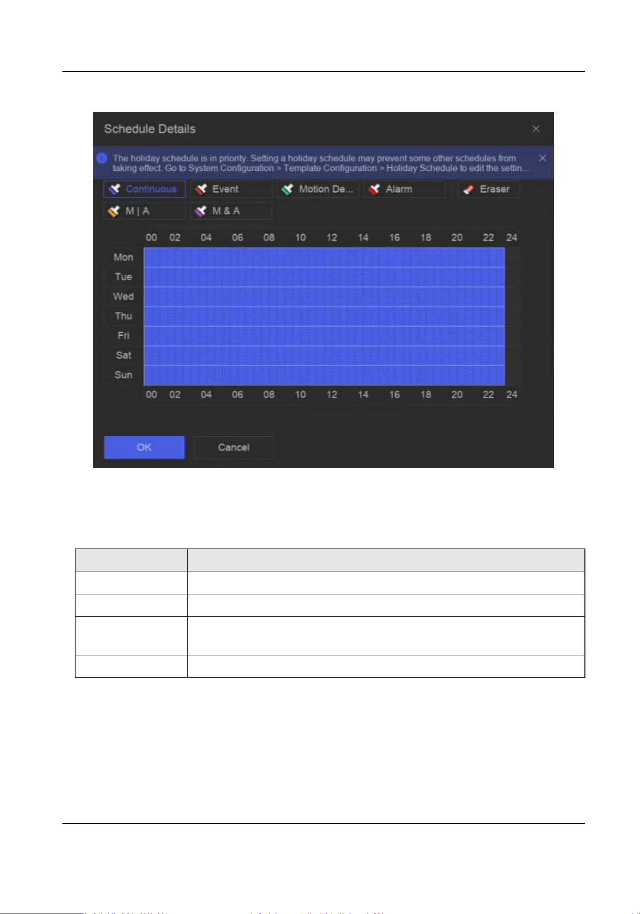
Figure 10-6 View Schedule
5.
Click under Advanced Sengs to set advanced picture parameters.
Table 10-2 Advanced Parameter
Descripon
Parameter Descripon
Capture Delay The duraon for picture capture.
Resoluon Set the resoluon of the picture to capture.
Picture Quality Set the picture quality to low, medium or high. High picture quality
requires more storage space.
Interval The me interval of capturing each live picture.
6.
Oponal: Select channels in the list, and use Batch Schedule Conguraon and Batch Advanced
Sengs to congure channels in a batch.
7.
Click Save.
Network Video Recorder User Manual
49

10.4 Congure Audio Recording
The device would automacally record audios according to the congured recording schedule.
Steps
1.
Go to System → Storage Management → Storage Schedule → Audio Recording .
2.
Turn on Enable for a channel.
3.
Select a schedule type.
Note
If you set Record Schedule as Custom, you can drag the cursor on me bar to set customized
record schedule, or move the cursor on me bar and click to set specied me
schedule.
4.
Click View to view the schedule.
5.
Oponal: Click under Advanced Sengs to set other advanced parameters.
Table 10-3 Advanced Parameter Descripon
Parameter Descripon
Pre-Record The me you set to record before the scheduled me or event. For
example, when an alarm triggers the recording at 10:00, and if you set the
pre-record me as 5 seconds, the channel records at 9:59:55.
Post-Record The me you set to record aer the event or the scheduled me. For
example, when an alarm triggered recording ends at 11:00, and if you set
the post-record me as 5 seconds, it records ll 11:00:05.
6.
Oponal: Select channels in the list, and use Batch Schedule Conguraon and Batch Advanced
Sengs to congure channels in a batch.
7.
Click Save.
Network Video Recorder User Manual
50
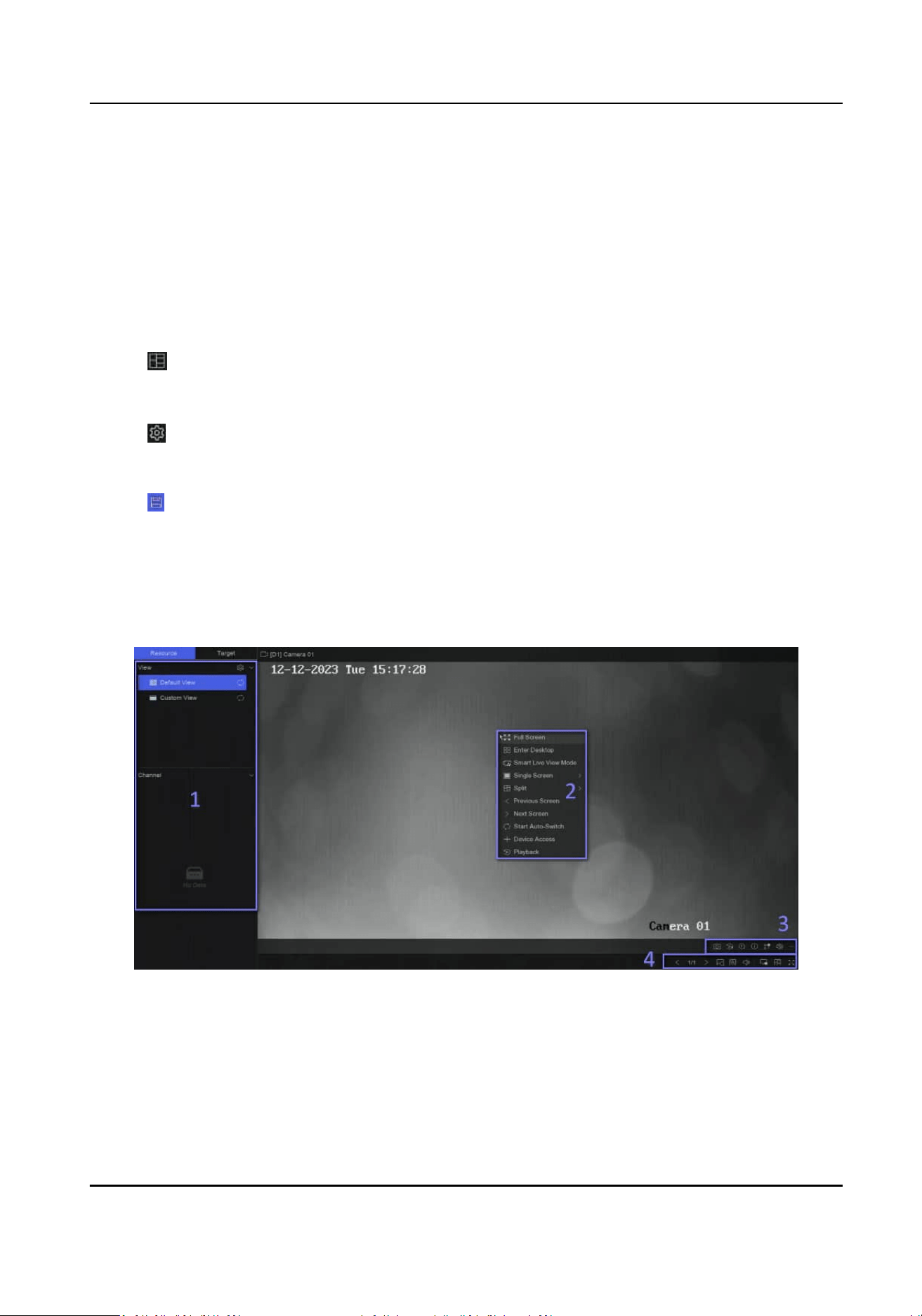
Chapter 11 Live View
11.1 Congure Live View Layout
Live view displays the video image of each camera in real me.
Steps
1.
Go to Live View.
2.
Click at the lower-right corner.
3.
Select a window division type, or click Custom to customize a new type as your desire.
4.
Move the cursor on Default View in View.
5.
Click
at the right side of View.
6.
Follow the step
descripons to adjust the live view image output interface. Besides the two ways
that are menoned on the user interface, you can drag a channel from one window to another.
7.
Click
.
11.2 GUI
Introducon
You can view live image, play live audio, capture pictures, perform instant playback, etc.
Figure 11-1 Live View (Type 1)
Network Video Recorder User Manual
51
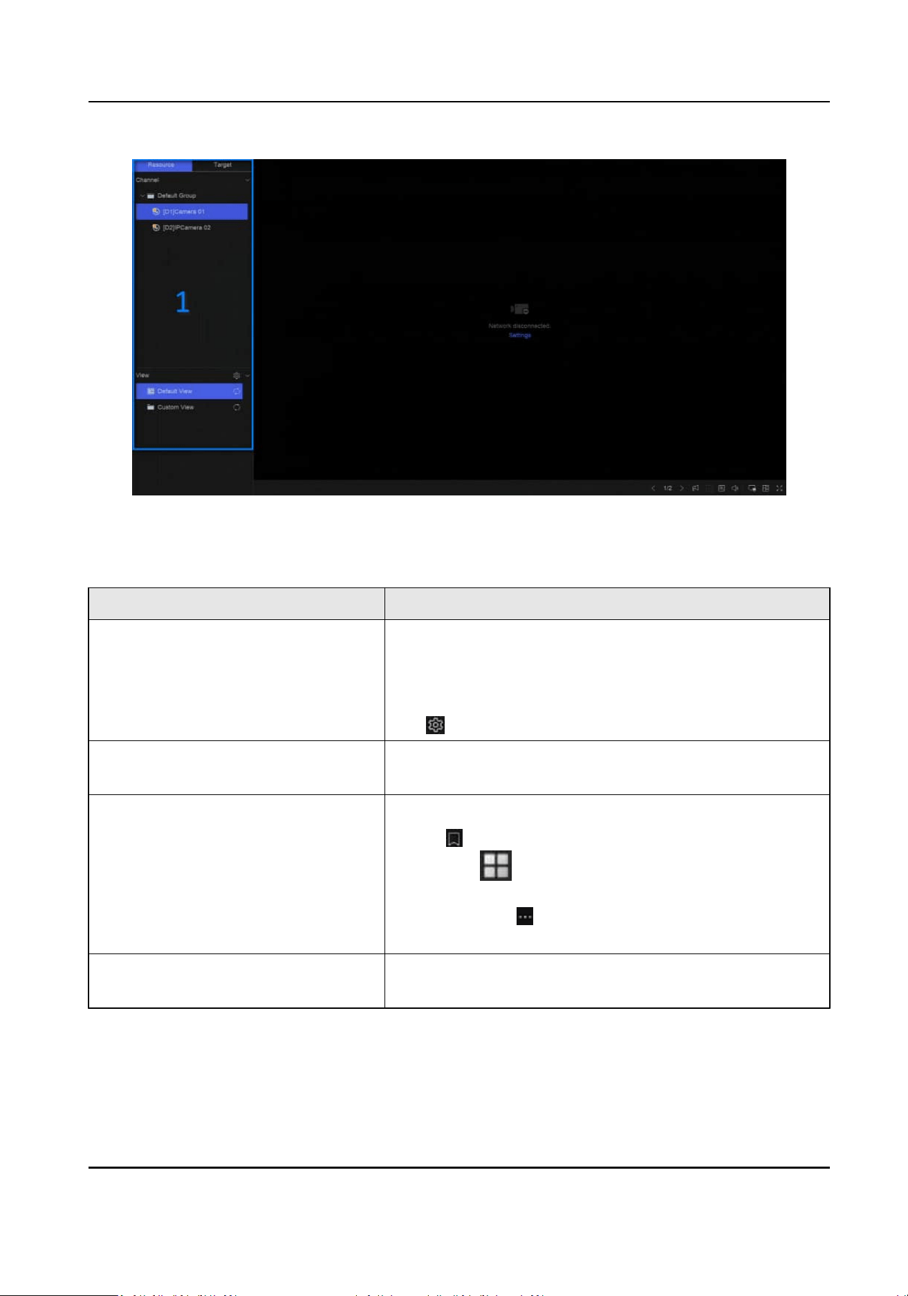
Figure 11-2 Live View (Type 2)
Table 11-1 Interface Descripon
No. Descripon
1 Channel list, PTZ control panel, and target detecon list. If
you select a channel from the channel list, the device will
redirect to the corresponding window. If you click Target,
you can view live target
detecon results in the list, and
click
to congure the corresponding sengs.
2 Right-click shortcut menu. It will appear aer right
clicking the cursor on the image area.
3 Channel tool bar.
●
Click to add a tag go the channel. Aer adding, you
can go to
→ Backup → By Tag to search videos by
tag.
●
You can select
→ Show VCA Info to display rule
frames.
4 Live view tool bar. Funcons like Voice Broadcast, Display
VCA Info and Switch Output can be performed here.
Network Video Recorder User Manual
52
Note
●
You can scroll up/down your mouse to turn to previous/next screen.
●
If channel image display excepon occurs, the corresponding window would show the error
message, and you can directly click the text (in blue color) to edit the device sengs.
11.3 PTZ Control
PTZ is the acronym for Pan, Tilt, and Zoom. Aer a PTZ camera is add to your device, the device
would be allowed to pan le and right, lt up and down, and zoom in and out.
Select a PTZ camera, and expend the PTZ control menu at the
lower-le corner.
Table 11-2 PTZ Operaon
Task Descripon Operaon
Preset Presets record the PTZ posion
and the status of zoom, focus,
iris, etc. You can call a preset to
quickly move the camera to the
predened posion.
Set a preset:
1. Select a preset.
2. Use to direcon buons to adjust the
image.
3. Click .
Call a preset: Click .
Patrol Patrols can be set to move the
PTZ to key points and have it stay
there for a set duraon before
moving on to the next key point.
The key points are correspond to
the presets.
Set a patrol:
1. Select a patrol.
2. Click
.
3. Add presets for the patrol.
4. Click OK.
Call a patrol: Click .
Paern Paerns can be set by recording
the movement of the PTZ. You
can call the paern to make the
PTZ move according to the
predened path.
Set a paern:
1. Click .
2. Use to direcon buons to adjust the
image, the device will record the
movement.
3. Stop recording.
Call a paern: Click .
Note
If the PTZ panel cannot be used, please click to check the sengs.
Network Video Recorder User Manual
53
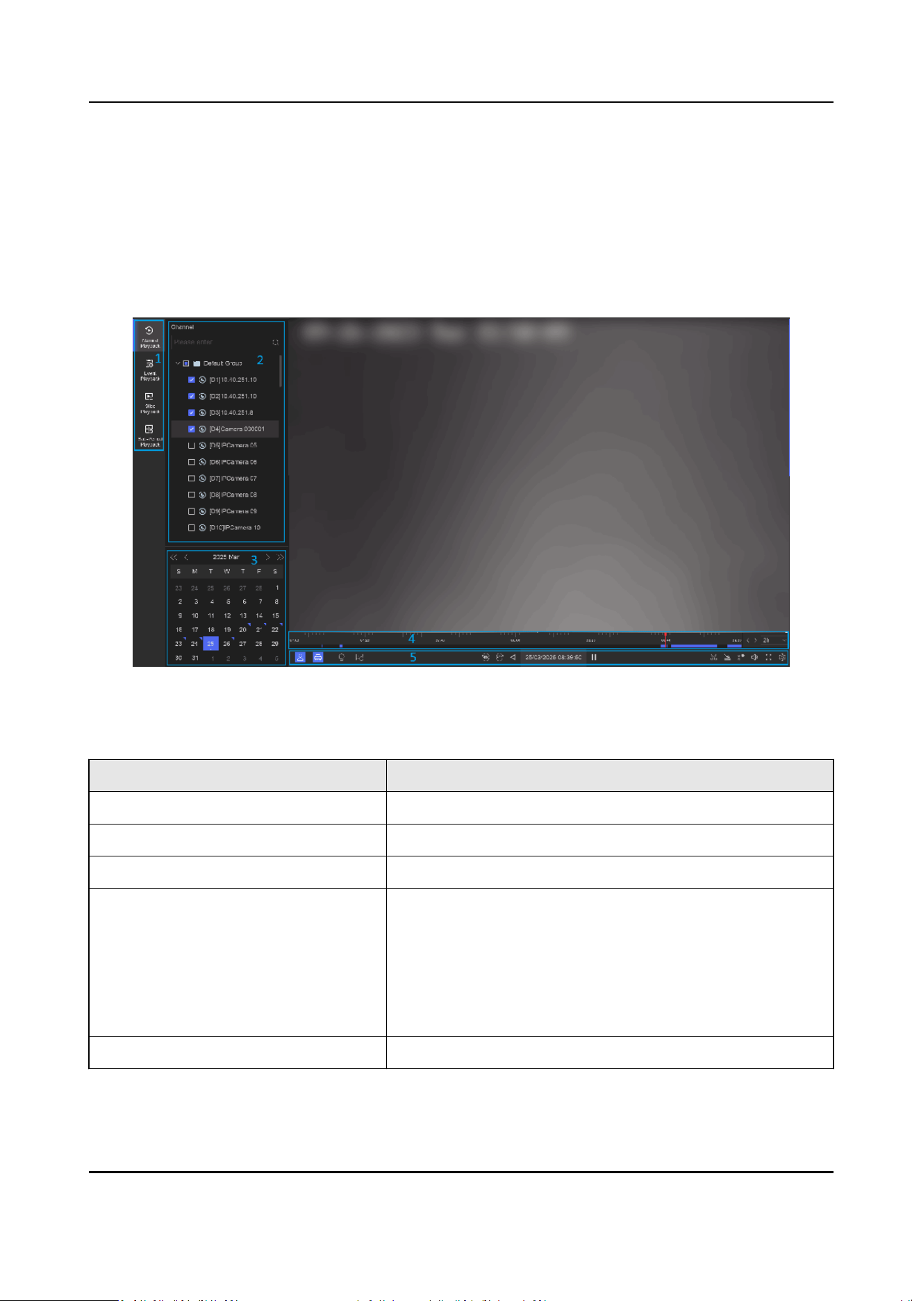
Chapter 12 Playback
12.1 GUI Introducon
You can play back video or audio les.
Figure 12-1 Playback
Table 12-1 Interface Descripon
No. Descripon
1 Area for selecng playback type.
2 Channel list.
3 Calendar for me selecon.
4 Playback meline.
●
Posion the cursor on the meline, drag the meline to
posion to a certain me.
●
Period marked with blue bar contains video. Red bar
indicates the video in the period is event video.
●
Scroll up/down to zoom out/in meline.
5 Playback tool bar.
Network Video Recorder User Manual
54
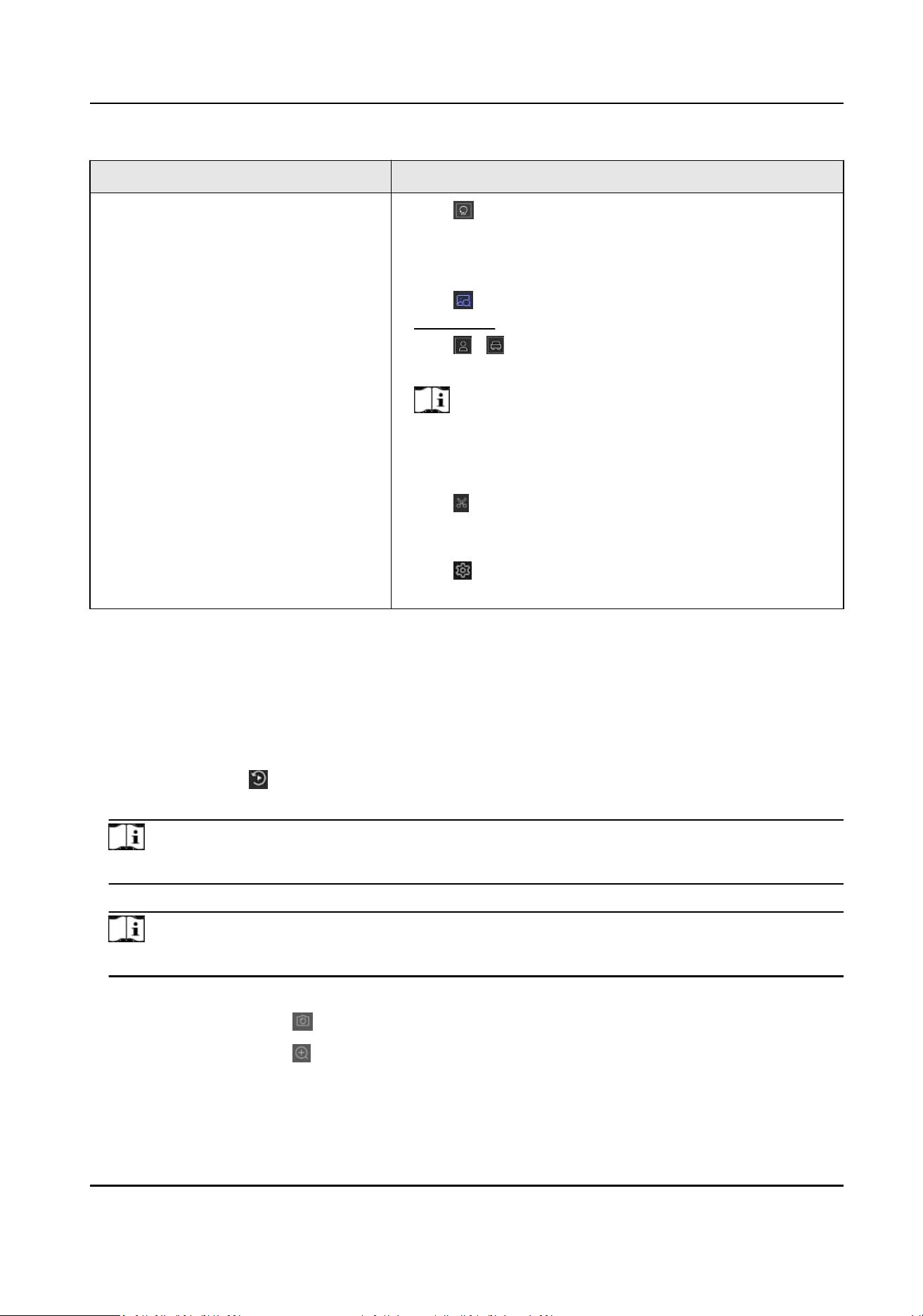
No. Descripon
●
Click (Smart Search), then follow the pop-up ps to
draw event rule and search videos that can trigger the
corresponding event rule. The operaons are similar
with Dual-VCA
funcon.
●
Click
to perform AcuSearch funcon. Refer to
AcuSearch for details.
●
Click
/ to show videos that contain human/
vehicle.
Note
In order to use this funcon, ensure you have
congured Detecon Target as Human or Vehicle for
certain event types.
●
Click
, select channels, and set the start and end me
to clip the video in the selected channels within specic
me period.
●
Click to set normal video and smart video (the video
that contains smart data) playback strategy.
12.2 Normal Playback
Play back videos for a channel. For certain devices, synchronous playback may be allowed for
several channels.
Steps
1.
Go to Playback → .
2.
Select channel(s) in the list at the
le side.
Note
Group playback: Select a group in the list, and channels in the group can be played back.
3.
Select a date in the calendar.
Note
The blue triangle at the calendar date corner indicates there are available videos.
4.
Oponal: Perform more operaons.
Capture
Click to capture pictures during playback.
Digital Zoom Click to zoom in a certain part of the video image.
Network Video Recorder User Manual
55

Click to add a tag to the channel. Aer adding, you can go to →
Backup → By Tag to search videos by tag.
Click to lock the video. Aer a video is locked, it will not be overwrien.
Aer locking, you can go to → Backup → By Tag to search videos by lock.
Dual-VCA Select → Dual-VCA to search videos that can trigger the corresponding
event rule. Refer to the event conguraon steps for details of each event
type.
Note
To use this funcon, go to Conguraon → Device Access → Device
Conguraon → Device Parameter → Display Info. on Scream to turn on
Enable Dual-VCA via web browser, and go to System → Storage
Management → Advanced
Sengs to turn on Save Camera VCA Data via
local GUI interface.
Show VCA
Info
You can select → Show VCA Info to display rule frames.
Disable
Privacy
Protecon
If privacy protecon is enabled, the image may contain mosaics. You can
select → Display Privacy Protecon to display the original video (without
mosaics) if the storage permission of privacy protecon is enabled as well.
Refer to
Congure Privacy Protecon for details about privacy protecon
funcon.
12.3 Event Playback
When you select the event playback mode, the system will analyze and mark videos that contain
the
moon detecon, line crossing detecon, or intrusion detecon informaon
Before You Start
●
Ensure the camera has enabled Dual-VCA. You can enable it via the camera web browser
interface in
Conguraon → Video/Audio → Display Info. on Stream .
●
Ensure your video recorder has enabled Save Camera VCA Data in Storage management →
Advanced
Sengs .
Steps
1.
Select Playback → .
2.
Select a date in the calendar.
Note
The blue triangle at the calendar date corner indicates there are available videos.
Network Video Recorder User Manual
56

3.
Click → Dual-VCA at the lower-right corner of playback image to select a event type. Refer to
the event conguraon steps for details of each event type.
4.
Click Search.
Videos meet the
detecon rule requirement will be marked in red.
5.
Click
to set normal video and smart video (the video that contains smart data) playback
strategy.
Note
If Dual-VCA is not used, red segments in progress bar means the smart videos are generated by
the original event.
12.4 Slice Playback
Divide the video into slices and play them back.
Steps
1.
Go to Playback →
.
2.
Select a camera from the camera list.
3.
Select a date on the calendar.
4.
Click Search.
The retrieved video will be divided into one-hour slices for playback.
5.
Oponal: Select an one-hour slice and click to divide it into one-minute slices for playback.
12.5 Sub-Period Playback
The video les can be played in mulple sub-periods simultaneously on the screen.
Steps
1.
Go to Playback →
.
2.
Select a camera.
3.
Set the start me and end me.
4.
Click Search.
Network Video Recorder User Manual
57
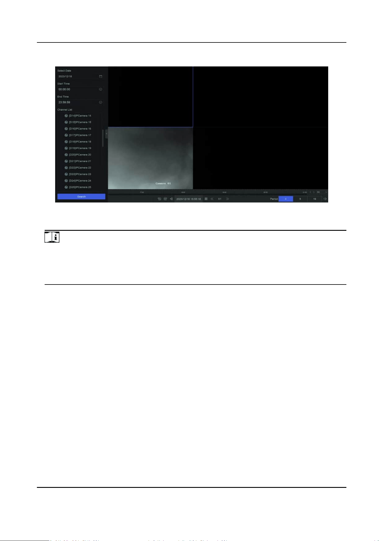
Figure 12-2 Sub-Period Playback
5.
Select the period at the lower-right corner, e.g., 4.
Note
According to the dened number of split-screens, the video les on the selected date can be
divided into average segments for playback. E.g., if there are video les exisng between 16:00
and 22:00, and the 6-screen display mode is selected, then it can play the video les for 1 hour
on each screen simultaneously.
Network Video Recorder User Manual
58

Chapter 13 Event Center
13.1 Event Sengs
13.1.1 Basic/Generic Event
Steps
1.
Go to Event Center → → Event Conguraon → Basic Event / Generic Event .
2.
Select a channel.
3.
Select an event type.
4.
Turn on Enable.
5.
Click Rule
Sengs to set the rule.
Table 13-1 Normal Event
Event Name Event Descripon Rule Conguraon
Moon
Detecon
Moon detecon detects
the moving objects in the
monitored area.
Use the tool bar at the
top of image to draw the
detecon area.
●
AI by NVR: The
moon
detecon
event will be
analyzed by NVR. The
device can analyze
videos that contain
human and vehicle.
Only the target of
selected type (human
or vehicle) will trigger
alarms, which can
reduce false alarms
that are caused by
other objects.
●
AI by Camera: The
moon detecon event
will be analyzed by
camera.
●
Detecon Target:
Human and Vehicle are
selectable, apart from
false alarms, only the
Sensivity
allows you to
calibrate how easily
movement could trigger
the alarm. A higher value
results in the more readily
to triggers
moon
detecon.
Network Video Recorder User Manual
59

Event Name Event Descripon Rule Conguraon
selected target(s) can
triggered alarms.
Video
Tampering
Detecon
Video tampering
detecon triggered an
alarm when the camera
lens is covered and takes
alarm response acon(s).
Use the tool bar at the
top of image to draw the
detecon area.
Video Loss
Detecon
Video loss detecon
detects video loss of a
channel and takes alarm
response
acon(s).
-
Audio
Excepon
Detecon
Audio excepon
detecon detects
abnormal sounds in the
scene, such as a sudden
increase/decrease in
sound intensity.
-
Defocus
Detecon
Image blur caused by lens
defocus can be detected.
-
Sudden
Scene
Change
Detecon
Scene change detecon
detects the change of the
video security
environment
aected by
external factors, such as
the intenonal rotaon of
the camera.
-
6.
Click Arming Schedule to select an arming schedule type.
Note
If you set Arming Schedule as Custom, you can drag the cursor on me bar to set customized
arming schedule, or move the cursor on me bar and click to set specied me
schedule.
7.
Click Linkage Method to set linkage methods.
Network Video Recorder User Manual
60

Table 13-2 Linkage Method Descripon
Linkage Method Descripon
Nofy Surveillance
Center
The device can send an excepon or alarm signal to the remote
alarm host when an event occurs. The alarm host refers to the PC
installed with client soware (e.g., iVMS-4200, iVMS-5200).
Alarm Pop-Up Window When an alarm is triggered, the local monitor displays the alarm
pop-up window.
Buzzer When an alarm is detected, the buzzer will make an audible beep.
Send Email The system can send an email with alarm informaon to a user or
users when an alarm is detected.
Alarm Output The alarm output can be triggered by the alarm input, moon
detecon, video tampering detecon, face detecon, line crossing
detecon, and any all other events.
Record When an alarm is detected, the selected channel would record
videos.
Note
Video recording schedule shall be enabled for the channel,
otherwise this linkage would be invalid. You can go to System →
Storage Management → Storage Schedule → Video Recording to
congure video recording schedule.
8.
Click Save.
13.1.2 Perimeter
Protecon
Perimeter protecon events include line crossing detecon, intrusion detecon, region entrance
detecon, and region exing detecon.
Congure
Line Crossing Detecon
Line crossing detecon detects people, vehicles, and objects crossing a set virtual line. The
detecon direcon can be set as bidireconal, from le to right or from right to le.
Steps
Note
A part of the following steps are only available for certain NVR or camera models.
1.
Go to Event Center → → Event Conguraon → Perimeter Protecon.
Network Video Recorder User Manual
61
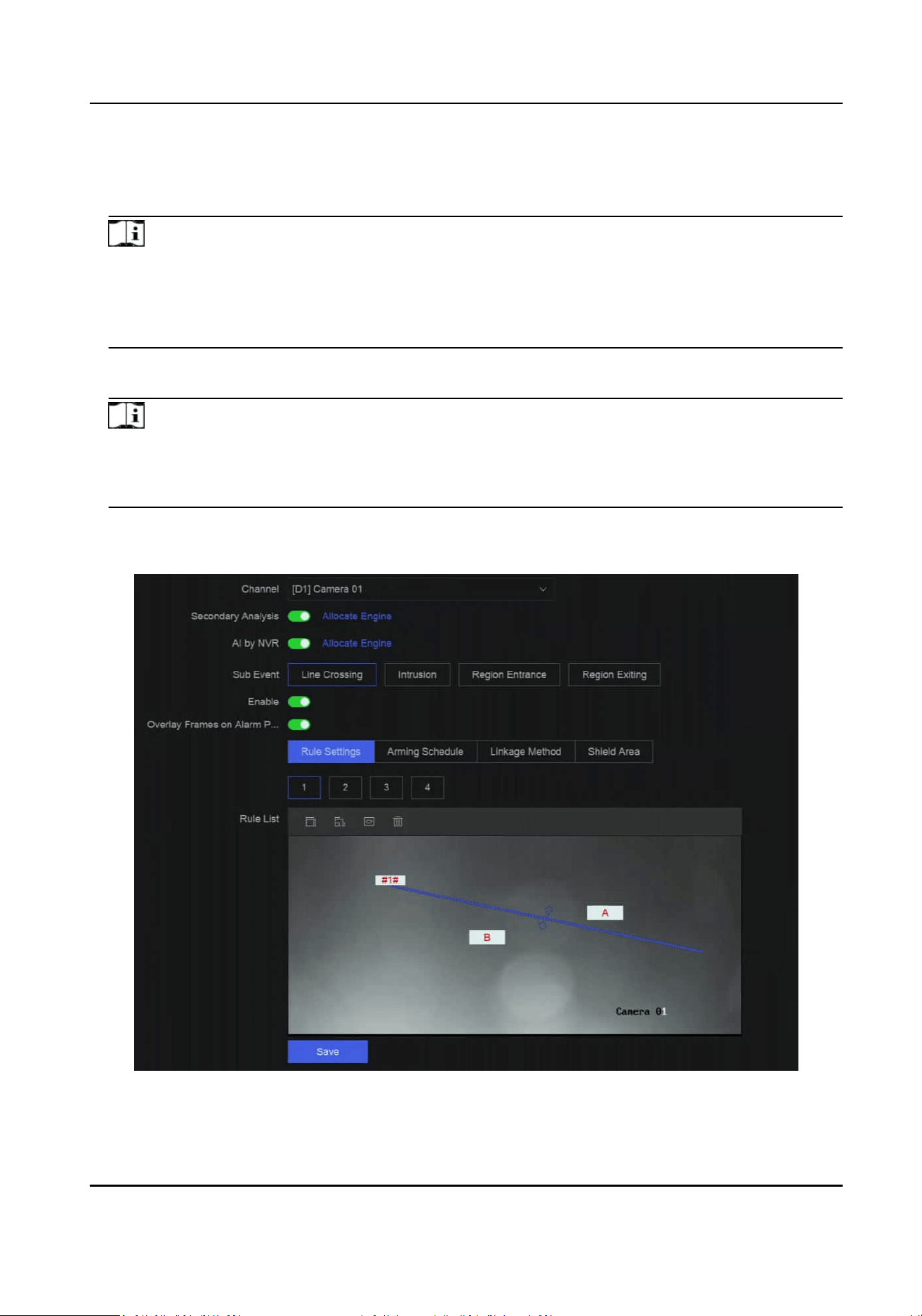
2.
Select a camera.
3.
Oponal: Turn on Secondary Analysis. The corresponding device engine will analyze this event
for a second me to reduce false alarms.
Note
At least one device engine should run Secondary Analysis for Perimeter Protecon algorithm.
You can click Allocate Engine at the right side to quickly allocate engine, or go to System →
Smart Sengs → Algorithm Conguraon → Algorithm Management to enable Secondary
Analysis for Perimeter
Protecon algorithm.
4.
Oponal: Turn on AI by NVR. The corresponding device engine will analyze the video, and
cameras only transmit video stream.
Note
At least one device engine should run Perimeter Protecon algorithm. You can click Allocate
Engine at the right side to quickly allocate engine, or go to System → Smart Sengs →
Algorithm Conguraon → Algorithm Management to enable Perimeter Protecon algorithm.
5.
Select Line Crossing.
6.
Turn on Enable.
Figure 13-1 Line Crossing Detecon
Network Video Recorder User Manual
62

7.
Click Rule Sengs to detecon rules.
1) Select a rule number. For example, select 1.
2) Click , and click on the image twice respecvely to draw the start point and end point of
the
detecon line.
3) Set
Direcon, Sensivity, Detecon Target, and Target Condence.
A<->B
Only the arrow on the B side shows. When an object goes across the
congured line with
both direcons can be detected and alarms are triggered.
A->B
Only the object crossing the
congured line from the A side to the B side can be detected.
B->A
Only the object crossing the congured line from the B side to the A side can be detected.
Sensivity
The higher the value is, the more easily the detecon alarm can be triggered.
Detecon Target
Select Detecon Target as Human or Vehicle to discard alarms which are not triggered by
human or vehicle. Detecon Target is only available for certain models.
Target Condence
It is used to indicate the level of certainty or reliability in detecng line crossing events.
Seng higher condence levels ensures that only highly reliable detecons trigger events,
reducing false alarms.
4) Oponal: Click / to draw Max. Size or Min. Size. Only targets that meet the size
requirement can trigger alarms.
5)
Oponal: Repeat above steps to draw more rules. Up to 4 rules are supports.
8.
Click Arming Schedule to select an arming schedule type.
Note
If you set Arming Schedule as Custom, you can drag the cursor on me bar to set customized
arming schedule, or move the cursor on me bar and click to set specied me
schedule.
9.
Click Linkage Method to set linkage methods.
Table 13-3 Linkage Method
Descripon
Linkage Method Descripon
Nofy Surveillance
Center
The device can send an excepon or alarm signal to the remote
alarm host when an event occurs. The alarm host refers to the PC
installed with client soware (e.g., iVMS-4200, iVMS-5200).
Alarm Pop-Up Window When an alarm is triggered, the local monitor displays the alarm
pop-up window.
Network Video Recorder User Manual
63

Linkage Method Descripon
Buzzer When an alarm is detected, the buzzer will make an audible beep.
Send Email The system can send an email with alarm informaon to a user or
users when an alarm is detected.
Alarm Output The alarm output can be triggered by the alarm input, moon
detecon, video tampering detecon, face detecon, line crossing
detecon, and any all other events.
Record When an alarm is detected, the selected channel would record
videos.
Note
Video recording schedule shall be enabled for the channel,
otherwise this linkage would be invalid. You can go to System →
Storage Management → Storage Schedule → Video Recording to
congure video recording schedule.
10.
Oponal: Set Shield Area when AI by NVR is enabled. Aer a shield area is set, the device will
not analyze target behavior in the area, so that the perimeter protecon events will not be
triggered within the area.
11.
Click Save.
What to do next
You can go to Live View and click Target to view
real-me alarms.
Congure
Intrusion Detecon
Intrusion detecon funcon detects people, vehicles or other objects that enter and loiter in a pre-
dened virtual region. Specic acons can be taken when an alarm is triggered.
Steps
Note
A part of the following steps are only available for certain NVR or camera models.
1.
Go to Event Center → → Event Conguraon → Perimeter Protecon.
2.
Select a camera.
3.
Oponal: Turn on Secondary Analysis. The corresponding device engine will analyze this event
for a second
me to reduce false alarms.
Network Video Recorder User Manual
64
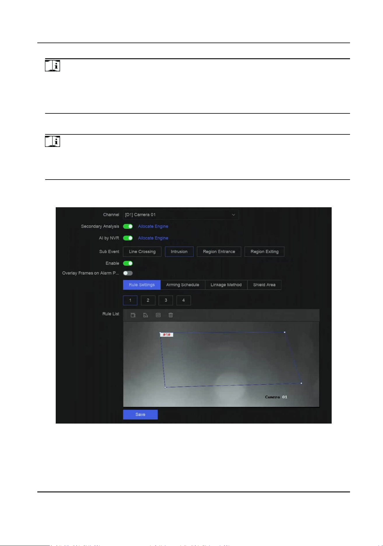
Note
At least one device engine should run Secondary Analysis for Perimeter Protecon algorithm.
You can click Allocate Engine at the right side to quickly allocate engine, or go to System →
Smart Sengs → Algorithm Conguraon → Algorithm Management to enable Secondary
Analysis for Perimeter
Protecon algorithm.
4.
Oponal: Turn on AI by NVR. The corresponding device engine will analyze the video, and
cameras only transmit video stream.
Note
At least one device engine should run Perimeter Protecon algorithm. You can click Allocate
Engine at the right side to quickly allocate engine, or go to System → Smart Sengs →
Algorithm Conguraon → Algorithm Management to enable Perimeter Protecon algorithm.
5.
Select Intrusion.
6.
Turn on Enable.
Figure 13-2 Intrusion Detecon
7.
Click Rule Sengs to detecon rules.
1) Select a rule number. For example, select 1.
Network Video Recorder User Manual
65

2) Click , and click on the image 4 mes respecvely to draw each point of a quadrilateral or
decagonal area.
3) Set Time Threshold, Sensivity, Detecon Target, and Target Condence.
Time Threshold
The me an object loiter in the region. When the duraon of the object in the dened
detecon
area exceeds the threshold, the device will trigger an alarm.
Sensivity
The higher the value is, the more easily the detecon alarm can be triggered.
Detecon Target
Select Detecon Target as Human or Vehicle to discard alarms which are not triggered by
human or vehicle. Detecon Target is only available for certain models.
Target Condence
It is used to indicate the level of certainty or reliability in detecng intrusion events. Seng
higher condence levels ensures that only highly reliable detecons trigger events,
reducing false alarms.
4) Oponal: Click / to draw Max. Size or Min. Size. Only targets that meet the size
requirement can trigger alarms.
5)
Oponal: Repeat above steps to draw more rules. Up to 4 rules are supports.
8.
Click Arming Schedule to select an arming schedule type.
Note
If you set Arming Schedule as Custom, you can drag the cursor on me bar to set customized
arming schedule, or move the cursor on me bar and click to set specied me
schedule.
9.
Click Linkage Method to set linkage methods.
Table 13-4 Linkage Method
Descripon
Linkage Method Descripon
Nofy Surveillance
Center
The device can send an excepon or alarm signal to the remote
alarm host when an event occurs. The alarm host refers to the PC
installed with client soware (e.g., iVMS-4200, iVMS-5200).
Alarm Pop-Up Window When an alarm is triggered, the local monitor displays the alarm
pop-up window.
Buzzer When an alarm is detected, the buzzer will make an audible beep.
Send Email The system can send an email with alarm informaon to a user or
users when an alarm is detected.
Network Video Recorder User Manual
66

Linkage Method Descripon
Alarm Output The alarm output can be triggered by the alarm input, moon
detecon, video tampering detecon, face detecon, line crossing
detecon, and any all other events.
Record When an alarm is detected, the selected channel would record
videos.
Note
Video recording schedule shall be enabled for the channel,
otherwise this linkage would be invalid. You can go to System →
Storage Management → Storage Schedule → Video Recording to
congure video recording schedule.
10.
Oponal: Set Shield Area when AI by NVR is enabled. Aer a shield area is set, the device will
not analyze target behavior in the area, so that the perimeter
protecon events will not be
triggered within the area.
11.
Click Save.
What to do next
You can go to Live View and click Target to view
real-me alarms.
Congure
Region Entrance Detecon
Region entrance detecon detects objects that enter a predened virtual region.
Steps
Note
A part of the following steps are only available for certain NVR or camera models.
1.
Go to Event Center → → Event Conguraon → Perimeter Protecon.
2.
Select a camera.
3.
Oponal: Turn on Secondary Analysis. The corresponding device engine will analyze this event
for a second
me to reduce false alarms.
Note
At least one device engine should run Secondary Analysis for Perimeter Protecon algorithm.
You can click Allocate Engine at the right side to quickly allocate engine, or go to System →
Smart Sengs → Algorithm Conguraon → Algorithm Management to enable Secondary
Analysis for Perimeter
Protecon algorithm.
4.
Oponal: Turn on AI by NVR. The corresponding device engine will analyze the video, and
cameras only transmit video stream.
Network Video Recorder User Manual
67
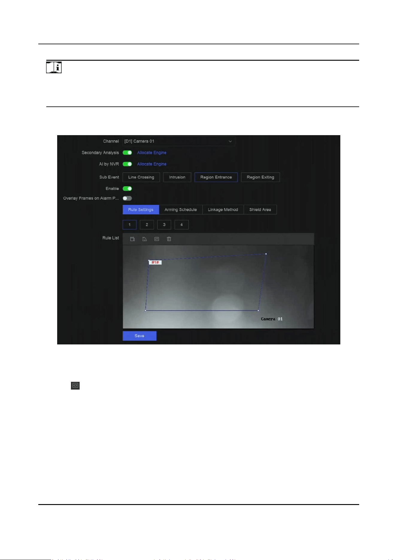
Note
At least one device engine should run Perimeter Protecon algorithm. You can click Allocate
Engine at the right side to quickly allocate engine, or go to System → Smart Sengs →
Algorithm Conguraon → Algorithm Management to enable Perimeter Protecon algorithm.
5.
Select Region Entrance.
6.
Turn on Enable.
Figure 13-3 Region Entrance Detecon
7.
Click Rule Sengs to detecon rules.
1) Select a rule number. For example, select 1.
2) Click , and click on the image 4 mes respecvely to draw each point of a quadrilateral or
decagonal area.
3) Set
Sensivity, Detecon Target, and Target Condence.
Sensivity
The higher the value is, the more easily the detecon alarm can be triggered.
Detecon Target
Select Detecon Target as Human or Vehicle to discard alarms which are not triggered by
human or vehicle. Detecon Target is only available for certain models.
Network Video Recorder User Manual
68

Target Condence
It is used to indicate the level of certainty or reliability in detecng region entrance events.
Seng higher condence levels ensures that only highly reliable detecons trigger events,
reducing false alarms.
4) Oponal: Repeat above steps to draw more rules. Up to 4 rules are supports.
8.
Click Arming Schedule to select an arming schedule type.
Note
If you set Arming Schedule as Custom, you can drag the cursor on me bar to set customized
arming schedule, or move the cursor on me bar and click to set specied me
schedule.
9.
Click Linkage Method to set linkage methods.
Table 13-5 Linkage Method Descripon
Linkage Method Descripon
Nofy Surveillance
Center
The device can send an excepon or alarm signal to the remote
alarm host when an event occurs. The alarm host refers to the PC
installed with client soware (e.g., iVMS-4200, iVMS-5200).
Alarm Pop-Up Window When an alarm is triggered, the local monitor displays the alarm
pop-up window.
Buzzer When an alarm is detected, the buzzer will make an audible beep.
Send Email The system can send an email with alarm informaon to a user or
users when an alarm is detected.
Alarm Output The alarm output can be triggered by the alarm input, moon
detecon, video tampering detecon, face detecon, line crossing
detecon, and any all other events.
Record When an alarm is detected, the selected channel would record
videos.
Note
Video recording schedule shall be enabled for the channel,
otherwise this linkage would be invalid. You can go to System →
Storage Management → Storage Schedule → Video Recording to
congure video recording schedule.
10.
Oponal: Set Shield Area when AI by NVR is enabled. Aer a shield area is set, the device will
not analyze target behavior in the area, so that the perimeter
protecon events will not be
triggered within the area.
11.
Click Save.
Network Video Recorder User Manual
69

What to do next
You can go to Live View and click Target to view real-me alarms.
Congure Region Exing Detecon
Region exing detecon detects objects that exit from a predened virtual region.
Steps
Note
A part of the following steps are only available for certain NVR or camera models.
1.
Go to Event Center → → Event Conguraon → Perimeter Protecon.
2.
Select a camera.
3.
Oponal: Turn on Secondary Analysis. The corresponding device engine will analyze this event
for a second
me to reduce false alarms.
Note
At least one device engine should run Secondary Analysis for Perimeter Protecon algorithm.
You can click Allocate Engine at the right side to quickly allocate engine, or go to System →
Smart Sengs → Algorithm Conguraon → Algorithm Management to enable Secondary
Analysis for Perimeter
Protecon algorithm.
4.
Oponal: Turn on AI by NVR. The corresponding device engine will analyze the video, and
cameras only transmit video stream.
Note
At least one device engine should run Perimeter Protecon algorithm. You can click Allocate
Engine at the right side to quickly allocate engine, or go to System → Smart Sengs →
Algorithm Conguraon → Algorithm Management to enable Perimeter Protecon algorithm.
5.
Select Region Exing.
6.
Turn on Enable.
Network Video Recorder User Manual
70
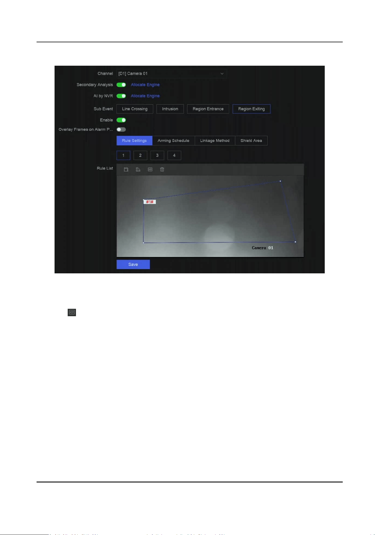
Figure 13-4 Region Exing Detecon
7.
Click Rule Sengs to detecon rules.
1) Select a rule number. For example, select 1.
2) Click
, and click on the image 4 mes respecvely to draw each point of a quadrilateral or
decagonal area.
3) Set Sensivity, Detecon Target, and Target Condence.
Sensivity
The higher the value is, the more easily the detecon alarm can be triggered.
Detecon Target
Select Detecon Target as Human or Vehicle to discard alarms which are not triggered by
human or vehicle. Detecon Target is only available for certain models.
Target Condence
It is used to indicate the level of certainty or reliability in detecng region exing events.
Seng higher condence levels ensures that only highly reliable detecons trigger events,
reducing false alarms.
4)
Oponal: Repeat above steps to draw more rules. Up to 4 rules are supports.
8.
Click Arming Schedule to select an arming schedule type.
Network Video Recorder User Manual
71

Note
If you set Arming Schedule as Custom, you can drag the cursor on me bar to set customized
arming schedule, or move the cursor on me bar and click to set specied me
schedule.
9.
Click Linkage Method to set linkage methods.
Table 13-6 Linkage Method Descripon
Linkage Method Descripon
Nofy Surveillance
Center
The device can send an excepon or alarm signal to the remote
alarm host when an event occurs. The alarm host refers to the PC
installed with client soware (e.g., iVMS-4200, iVMS-5200).
Alarm Pop-Up Window When an alarm is triggered, the local monitor displays the alarm
pop-up window.
Buzzer When an alarm is detected, the buzzer will make an audible beep.
Send Email The system can send an email with alarm informaon to a user or
users when an alarm is detected.
Alarm Output The alarm output can be triggered by the alarm input, moon
detecon, video tampering detecon, face detecon, line crossing
detecon, and any all other events.
Record When an alarm is detected, the selected channel would record
videos.
Note
Video recording schedule shall be enabled for the channel,
otherwise this linkage would be invalid. You can go to System →
Storage Management → Storage Schedule → Video Recording to
congure video recording schedule.
10.
Oponal: Set Shield Area when AI by NVR is enabled. Aer a shield area is set, the device will
not analyze target behavior in the area, so that the perimeter protecon events will not be
triggered within the area.
11.
Click Save.
What to do next
You can go to Live View and click Target to view
real-me alarms.
13.1.3 Abnormal Behavior Event
Before You Start
Ensure the camera supports this funcon.
Network Video Recorder User Manual
72

Steps
1.
Go to Event Center → → Event Conguraon → Abnormal Behavior Event .
2.
Select a camera
3.
Select an event type.
4.
Turn on Enable.
5.
Click Rule
Sengs to set the rule.
Table 13-7 Abnormal Behavior Events
Event Name Event Descripon Rule Conguraon
Loitering
Detecon
Loitering detecon is used to
detect whether a target stays
within a specied area longer
than the set
me and trigger
alarm for linked
acons.
a. Select a rule number.
b. Use the tool bar at the top of image to draw
the detecon line.
c. Set Time Threshold and
Sensivity.
Time Threshold
The me of the target staying in the
region. If the value is 10, an alarm is
triggered aer the target has stayed in
the region for 10 s. Range: [1-10].
Sensivity
Similarity of the background image to
the object. The higher the value is, more
easily the
detecon alarm will be
triggered.
d. Oponal: Repeat the above steps to set
another one.
Parking
Detecon
Parking detecon is used to
detect parking violaon in the
area, applicable in expressway
and one-way street.
Unaended
Baggage
Detecon
Unaended baggage
detecon detects the objects
le over in a predened
region such as the baggage,
purses, dangerous materials,
etc., and a series of acons
can be taken when the alarm
is triggered.
Object
Removal
Detecon
The object removal detecon
funcon detects the objects
removed from a predened
region, such as the exhibits on
display, and a series of
acons
can be taken when the alarm
is triggered.
Fast Moving
Detecon
Fast moving detecon is used
to detect suspicious running
and chasing, over-speed, and
fast moving. It will trigger
alarm when an object is
moving fast and send
nocaon to arming host so
Network Video Recorder User Manual
73

Event Name Event Descripon Rule Conguraon
that necessary acons can be
taken in advance.
People
Gathering
Detecon
People gathering detecon is
used to detect whether the
density of human bodies
within a
specied area
exceeds the set value and
trigger alarm for linked
acons.
a. Select a rule number.
b. Use the tool bar at the top of image to draw
the
detecon line.
c. Set Percentage. Percentage is the density of
human bodies within the area. If it exceeds
the threshold value, the device will trigger
alarm.
d.
Oponal: Repeat the above steps to set
another one.
6.
Click Arming Schedule to select an arming schedule type.
Note
If you set Arming Schedule as Custom, you can drag the cursor on me bar to set customized
arming schedule, or move the cursor on me bar and click to set specied me
schedule.
7.
Click Linkage Method to set linkage methods.
Table 13-8 Linkage Method
Descripon
Linkage Method Descripon
Nofy Surveillance
Center
The device can send an excepon or alarm signal to the remote
alarm host when an event occurs. The alarm host refers to the PC
installed with client soware (e.g., iVMS-4200, iVMS-5200).
Alarm Pop-Up Window When an alarm is triggered, the local monitor displays the alarm
pop-up window.
Buzzer When an alarm is detected, the buzzer will make an audible beep.
Send Email The system can send an email with alarm informaon to a user or
users when an alarm is detected.
Alarm Output The alarm output can be triggered by the alarm input, moon
detecon, video tampering detecon, face detecon, line crossing
detecon, and any all other events.
Record When an alarm is detected, the selected channel would record
videos.
Network Video Recorder User Manual
74

Linkage Method Descripon
Note
Video recording schedule shall be enabled for the channel,
otherwise this linkage would be invalid. You can go to System →
Storage Management → Storage Schedule → Video Recording to
congure video recording schedule.
8.
Click Save.
13.1.4 Target Event
Before You Start
Ensure the connected camera supports this
funcon, or the device engine has enabled Target
Recognion or Video Structuralizaon algorithm in Event Center → Event Conguraon → Smart
Sengs → Algorithm Conguraon → Algorithm Management .
Steps
1.
Go to Event Center → → Event Conguraon → Target Event .
2.
Select a camera.
3.
Select an event.
4.
Turn on Enable.
5.
Set event rules.
Event Name
Event Descripon Rule Conguraon
Face Capture The face capture detects and
captures faces appearing in
the scene. Linkage acons can
be triggered when a human
face is detected.
-
Face Picture
Comparison
The funcon compares
detected face pictures with
specied list library. Trigger
alarm when comparison
succeeded.
●
Supports conguring target grading. Face
picture comparison begins when the grade
of target meets the comparison
requirements (the pupil distance are bigger
than the congured threshold, and the lt
angle and pan angle are smaller than the
congured thresholds).
●
Supports
conguring prompts for failed and
succeeded comparisons.
Network Video Recorder User Manual
75

Event Name Event Descripon Rule Conguraon
Stranger
Detecon
Faces not in the list library
appearing in the video will be
idened as strangers.
●
Supports conguring target grading. Face
picture comparison begins when the grade
of target meets the comparison
requirements (the pupil distance are bigger
than the congured threshold, and the lt
angle and pan angle are smaller than the
congured thresholds).
●
Supports
conguring the prompt for
detecng strangers.
Mul-Target-
Type
Detecon
Mul-target-type detecon
enables the device to detect
the faces, human bodies and
vehicles simultaneously in a
scene.
-
6.
Click Arming Schedule to select an arming schedule type.
Note
If you set Arming Schedule as Custom, you can drag the cursor on me bar to set customized
arming schedule, or move the cursor on me bar and click to set specied me
schedule.
7.
Click Linkage Method to set linkage methods.
Table 13-9 Linkage Method
Descripon
Linkage Method Descripon
Nofy Surveillance
Center
The device can send an excepon or alarm signal to the remote
alarm host when an event occurs. The alarm host refers to the PC
installed with client soware (e.g., iVMS-4200, iVMS-5200).
Alarm Pop-Up Window When an alarm is triggered, the local monitor displays the alarm
pop-up window.
Buzzer When an alarm is detected, the buzzer will make an audible beep.
Send Email The system can send an email with alarm informaon to a user or
users when an alarm is detected.
Alarm Output The alarm output can be triggered by the alarm input, moon
detecon, video tampering detecon, face detecon, line crossing
detecon, and any all other events.
Record When an alarm is detected, the selected channel would record
videos.
Network Video Recorder User Manual
76

Linkage Method Descripon
Note
Video recording schedule shall be enabled for the channel,
otherwise this linkage would be invalid. You can go to System →
Storage Management → Storage Schedule → Video Recording to
congure video recording schedule.
8.
Click Save.
13.1.5 Thermal Camera Detecon
The NVR supports the event detecon modes of the thermal network cameras: re and smoke
detecon, temperature detecon, temperature dierence detecon, etc.
Before You Start
Add the thermal network camera to your device and make sure the camera is acvated.
Steps
1.
Go to Event Center →
→ Event Conguraon → Thermal Event .
2.
Select a camera.
3.
Select an event type.
4.
Turn on Enable.
5.
Click Rule
Sengs to set the rule.
Table 13-10 Thermal Events
Event Name Event Descripon
Fire Detecon An alarm would be triggered when re is detected in the
arming area.
Temperature Detecon An alarm would be triggered when the temperature exceeds
the threshold value.
Perimeter Protecon Perimeter protecon events include line crossing detecon,
intrusion detecon, region entrance detecon, and region
exing detecon.
6.
Click Arming Schedule to select an arming schedule type.
Note
If you set Arming Schedule as Custom, you can drag the cursor on me bar to set customized
arming schedule, or move the cursor on me bar and click to set specied me
schedule.
7.
Click Linkage Method to set linkage methods.
Network Video Recorder User Manual
77

Table 13-11 Linkage Method Descripon
Linkage Method Descripon
Nofy Surveillance
Center
The device can send an excepon or alarm signal to the remote
alarm host when an event occurs. The alarm host refers to the PC
installed with client soware (e.g., iVMS-4200, iVMS-5200).
Alarm Pop-Up Window When an alarm is triggered, the local monitor displays the alarm
pop-up window.
Buzzer When an alarm is detected, the buzzer will make an audible beep.
Send Email The system can send an email with alarm informaon to a user or
users when an alarm is detected.
Alarm Output The alarm output can be triggered by the alarm input, moon
detecon, video tampering detecon, face detecon, line crossing
detecon, and any all other events.
Record When an alarm is detected, the selected channel would record
videos.
Note
Video recording schedule shall be enabled for the channel,
otherwise this linkage would be invalid. You can go to System →
Storage Management → Storage Schedule → Video Recording to
congure video recording schedule.
8.
Click Save.
13.1.6 Alarm Input Event
Set the handling acon of an external sensor alarm.
Steps
1.
Go to Event Center → → Event Conguraon → Alarm Input Event .
2.
Select an alarm input name.
Network Video Recorder User Manual
78
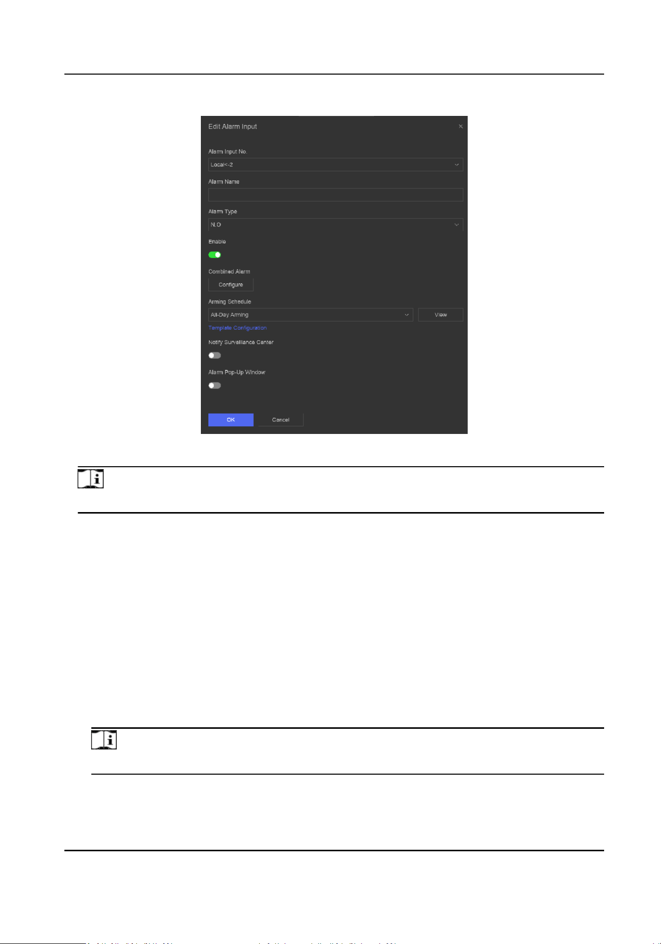
Figure 13-5 Congure Alarm Input
Note
For example, Local<-1 represents the alarm input number at the device rear panel is 1.
3.
Edit Alarm Name.
4.
Set Alarm Type.
N.O
When contacts are in natural and
o-power state, if two contacts are o, then they can be
called normal open.
N.C
When contacts are in natural and o-power state, if two contacts are conducted, then they
can be called normal closed.
5.
Turn on Enable.
6.
Oponal: If you select Local<-1 in Step 2, select the processing method.
-
Select Process Alarm Input, and then you can set the corresponding arming schedule, linkage
methods, etc.
Note
The operaons below are all available when you select this processing method.
-
Select Quick Disarming, and then linkage methods of all events will be disabled.
7.
Click Congure to congure combined alarm.
Network Video Recorder User Manual
79

1) Select a channel.
2) Select combined alarm events such as moon detecon and video tampering detecon.
3) Click OK.
The combined alarm will be triggered when it receives alarms from both alarm input and events.
8.
Click Arming Schedule to select an arming schedule type.
Note
If you set Arming Schedule as Custom, you can drag the cursor on me bar to set customized
arming schedule, or move the cursor on me bar and click to set specied me
schedule.
9.
Click Linkage Method to set linkage methods.
Table 13-12 Linkage Method Descripon
Linkage Method Descripon
Nofy Surveillance
Center
The device can send an excepon or alarm signal to the remote
alarm host when an event occurs. The alarm host refers to the PC
installed with client soware (e.g., iVMS-4200, iVMS-5200).
Alarm Pop-Up Window When an alarm is triggered, the local monitor displays the alarm
pop-up window.
Buzzer When an alarm is detected, the buzzer will make an audible beep.
Send Email The system can send an email with alarm informaon to a user or
users when an alarm is detected.
Alarm Output The alarm output can be triggered by the alarm input, moon
detecon, video tampering detecon, face detecon, line crossing
detecon, and any all other events.
Record When an alarm is detected, the selected channel would record
videos.
Note
Video recording schedule shall be enabled for the channel,
otherwise this linkage would be invalid. You can go to System →
Storage Management → Storage Schedule → Video Recording to
congure video recording schedule.
10.
Click Save.
13.1.7 Audio Analysis Event
Steps
1.
Go to Event Center → → Event Conguraon → Audio Analysis .
Network Video Recorder User Manual
80

2.
Select a channel.
3.
Select an event type.
4.
Turn on Enable.
5.
Click Rule
Sengs to set the rule.
Table 13-13 Audio Analysis Event
Event Name Event Descripon Rule Conguraon
Audio
Excepon
Detecon
Audio excepon
detecon detects
abnormal sounds in
the scene, such as a
sudden increase/
decrease in sound
intensity.
Sudden Increase of Sound Intensity Detecon
Detects a steep sound increase in the scene.
Sudden Decrease of Sound Intensity Detecon
Detects a steep sound drop in the scene.
Sensivity
The higher the value is, the easier the detecon
alarm can be triggered.
Sound Intensity Threshold
It can
lter the sound in the environment. The louder
the environment sound is, the higher the value
should be. Adjust it according to the environment.
6.
Click Arming Schedule to select an arming schedule type.
Note
If you set Arming Schedule as Custom, you can drag the cursor on me bar to set customized
arming schedule, or move the cursor on me bar and click to set specied me
schedule.
7.
Click Linkage Method to set linkage methods.
Table 13-14 Linkage Method
Descripon
Linkage Method Descripon
Nofy Surveillance
Center
The device can send an excepon or alarm signal to the remote
alarm host when an event occurs. The alarm host refers to the PC
installed with client soware (e.g., iVMS-4200, iVMS-5200).
Alarm Pop-Up Window When an alarm is triggered, the local monitor displays the alarm
pop-up window.
Buzzer When an alarm is detected, the buzzer will make an audible beep.
Send Email The system can send an email with alarm informaon to a user or
users when an alarm is detected.
Network Video Recorder User Manual
81

Linkage Method Descripon
Alarm Output The alarm output can be triggered by the alarm input, moon
detecon, video tampering detecon, face detecon, line crossing
detecon, and any all other events.
Record When an alarm is detected, the selected channel would record
videos.
Note
Video recording schedule shall be enabled for the channel,
otherwise this linkage would be invalid. You can go to System →
Storage Management → Storage Schedule → Video Recording to
congure video recording schedule.
8.
Click Save.
13.2 Linkage
Conguraon
Congure parameters for event linkages.
Steps
1.
Go to Event Center → → Event Conguraon → Linkage Conguraon or System → Event
Conguraon → → Event Conguraon → Linkage Conguraon.
2.
Click Email to
congure email parameters.
Table 13-15 Email Linkage
Item Descripon
Server Authencaon Enable it if the SMTP server requires user authencaon and
enter the user name and password accordingly.
SMTP Server The IP address of SMTP Server or host name (e.g., smtp.
263xmail.com).
SMTP Port The SMTP port. The default TCP/IP port used for SMTP is 25.
Enable SSL/TLS Enable SSL/TLS if the SMTP server has the requirement.
Sender The sender name.
Sender's Address The sender's address.
Select Receivers Select the receiver. Up to 3 receivers can be congured.
Aached Image Send email with aached alarm images.
Network Video Recorder User Manual
82
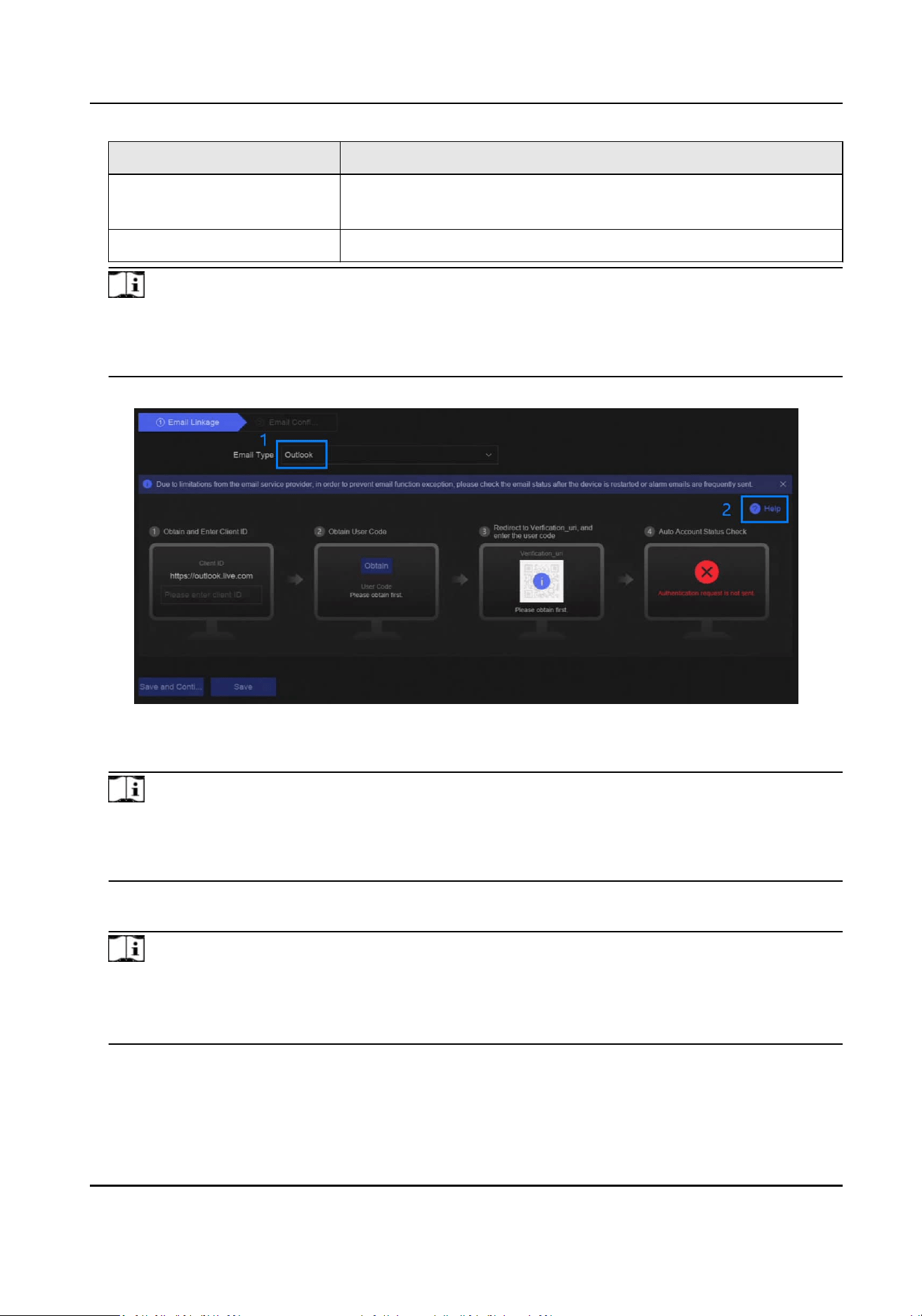
Item Descripon
Enable 3 Aached Images
for Perimeter Protecon
When a perimeter protecon event is triggered, the device
would send an email with 3 aached alarm images.
Interval The me interval for capturing the aached images.
Note
If you are using an Outlook email account, please set Email Type as Outlook, and click Help at
the right side to read the conguraon instrucons, then follow the steps on the interface to
complete the conguraon.
Figure 13-6 Outlook Email Conguraon
3.
Click Audio Management to manage audio les for alarm linkage.
Note
There are 3 default audio les in the list which cannot be deleted. You can import audio les
from USB ash drive. The les shall in AAC or MP3 format, and each le size should be within 1
MB.
4.
If you have connected IP speakers, click IP Speaker to import audio les in to the selected IP
speaker(s) for alarm linkage.
Note
●
This linkage acon is only available for few event types.
●
The uploaded audio le shoud be in MP3, WAV, or ACC format, and the le size should be less
than 1 MB.
5.
Click Alarm Output to set alarm output parameters.
Network Video Recorder User Manual
83

Note
●
Click the name of each alarm output to edit it.
●
The alarm output No. is the same as the one at the device rear panel. For example, Local->1
means the alarm out No. 1 at the device rear panel.
Delay
The alarm signal
duraon.
Alarm Status
Click Trigger to switch the status.
6.
If you have connected audio and light cameras, click Camera Audio and Light Conguraon to
congure the camera ashing light and camera speaker parameters for alarm linkage.
Note
This linkage acon is only available for few event types.
7.
If you have connected security control panels, click Security Control Panel to congure
parameters including IP address and port number.
13.3 Disarming
Conguraon
Aer a disarming template is congured, you can use the template to disarm channels in a batch.
The channels that have enabled Allow Disarming would not trigger the alarm linkage items
according the disarming template.
Steps
1.
Go to Event Center →
→ Event Conguraon → Linkage Conguraon or System → Event
Conguraon → → Event Conguraon → Linkage Conguraon.
Network Video Recorder User Manual
84
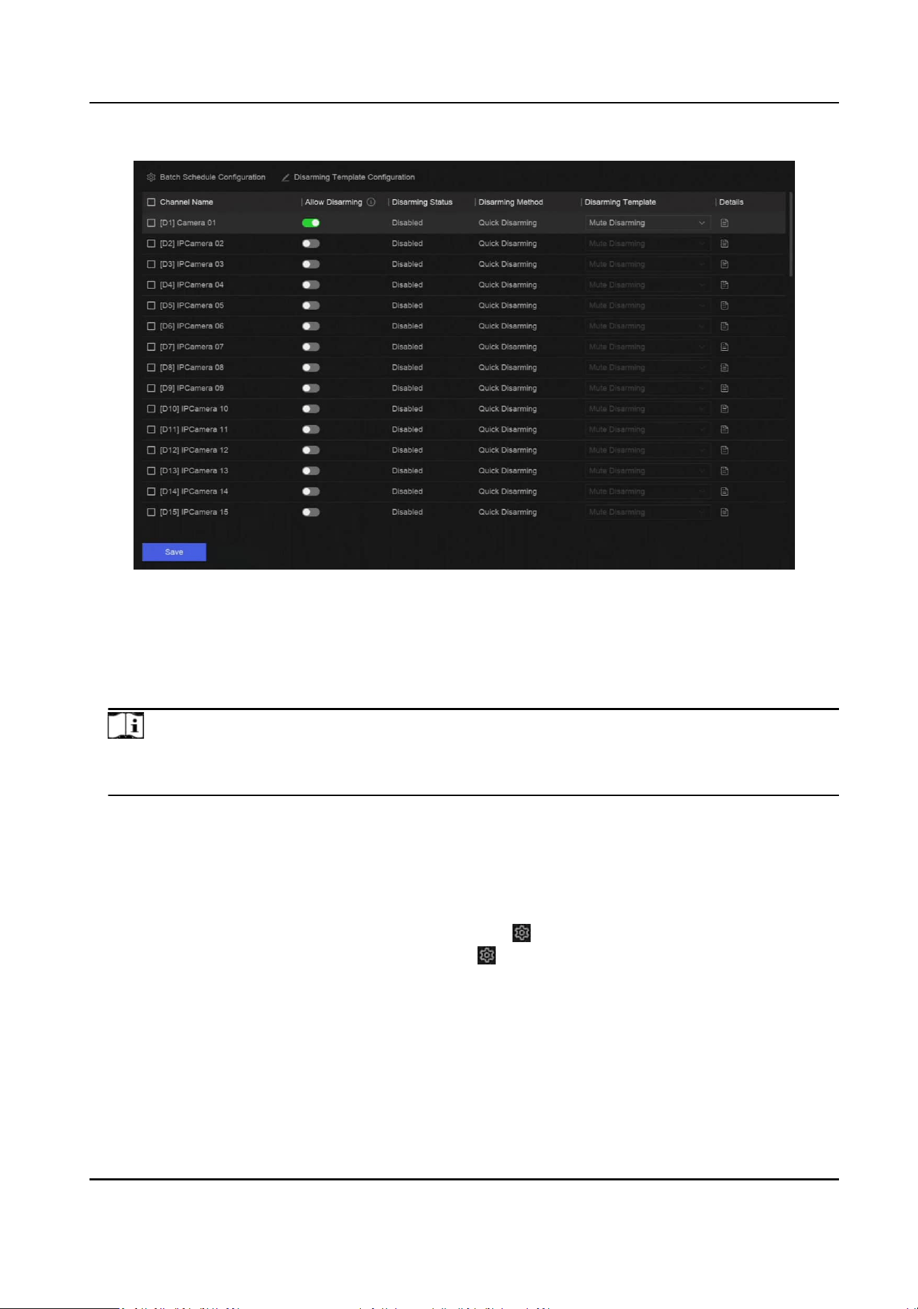
Figure 13-7 Disarming Conguraon
2.
Select channel(s) that are allowed for disarming.
3.
Click Batch Schedule
Conguraon.
4.
Turn onEnable.
5.
Select Disarming Template. Only two types are available
Note
Currently, only two template types are available and each template parameters cannot
congured.
6.
Click OK.
13.4 Batch
Conguraon
The listed events and the corresponding linkage acon of Nofy Surveillance Center can be
enabled or disabled in batches through Event Center → → Event Conguraon → Batch
Conguraon or System → Event Conguraon → → Event Conguraon → Batch
Conguraon. Aer an event is enabled, please click Go to Event Conguraon to set rules.
Network Video Recorder User Manual
85
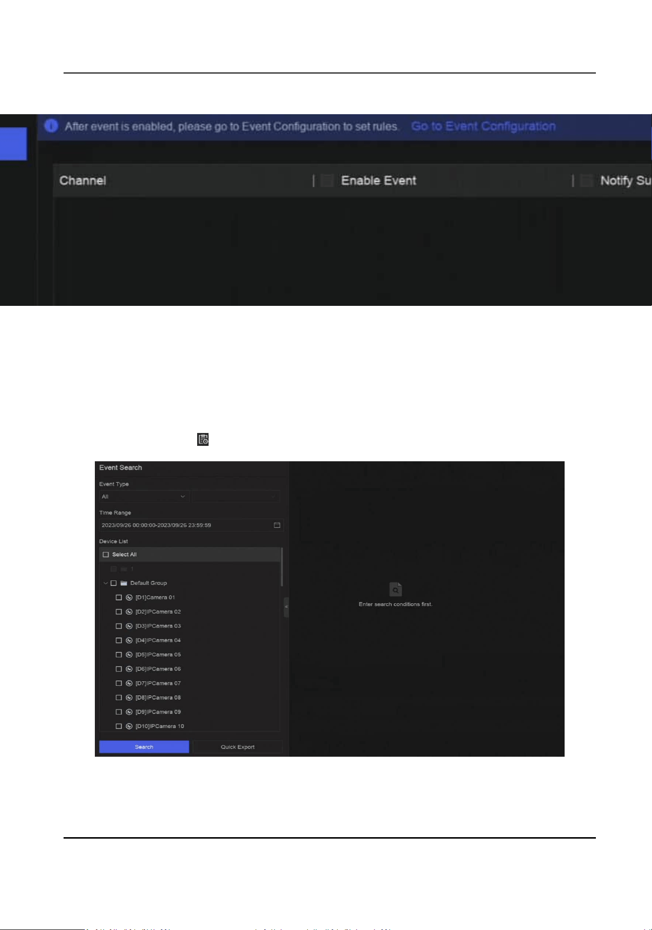
Figure 13-8 Batch Conguraon
13.5 Event Search
You can search event les like videos and pictures according to the searching condion.
Steps
1.
Go to Event Center →
.
Figure 13-9 Event Search
Network Video Recorder User Manual
86

2.
Specify detailed condions, including event type, me, channel, etc.
3.
Click Search.
The device will display the searching results of the selected channel(s).
What to do next
Select the items from the result list and export them for backup.
13.6 View Alarms
You can view real-me alarm videos and pictures, and play them back.
Steps
1.
Go to Event Center → .
2.
Click Real-Time Alarm.
3.
Select the alarm from the list.
If there are too many alarms, click Filter to search and
nd the alarm.
4.
Click Playback, and the alarm recording video would be played back.
5.
View the alarm picture(s) at the right side. The number of available pictures would be listed.
Network Video Recorder User Manual
87
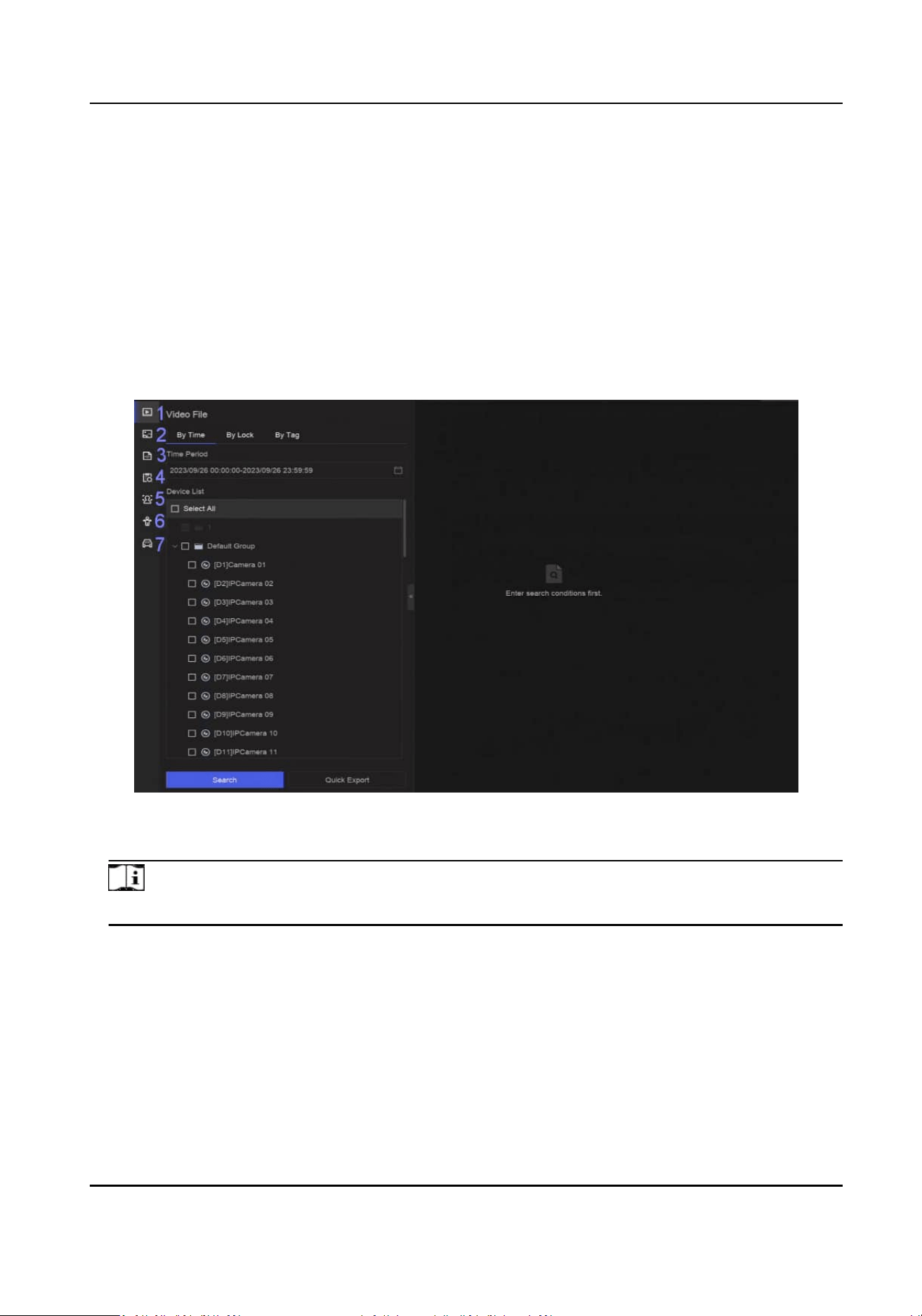
Chapter 14 Search and Backup
You can search les according to dierent searching condions, including le type, event type,
me, tag, etc. The searching results can be exported to another device, such as a USB ash drive.
Before You Start
Ensure HDD is correctly installed and recording parameters are properly congured.
Steps
1.
Go to Backup.
Figure 14-1 Search and Backup
2.
Choose a searching method from at the le side as your desire, 7 types are supported.
Note
The searching condions would vary according to the selected searching method.
3.
Set the searching condions.
4.
Click Search.
Network Video Recorder User Manual
88
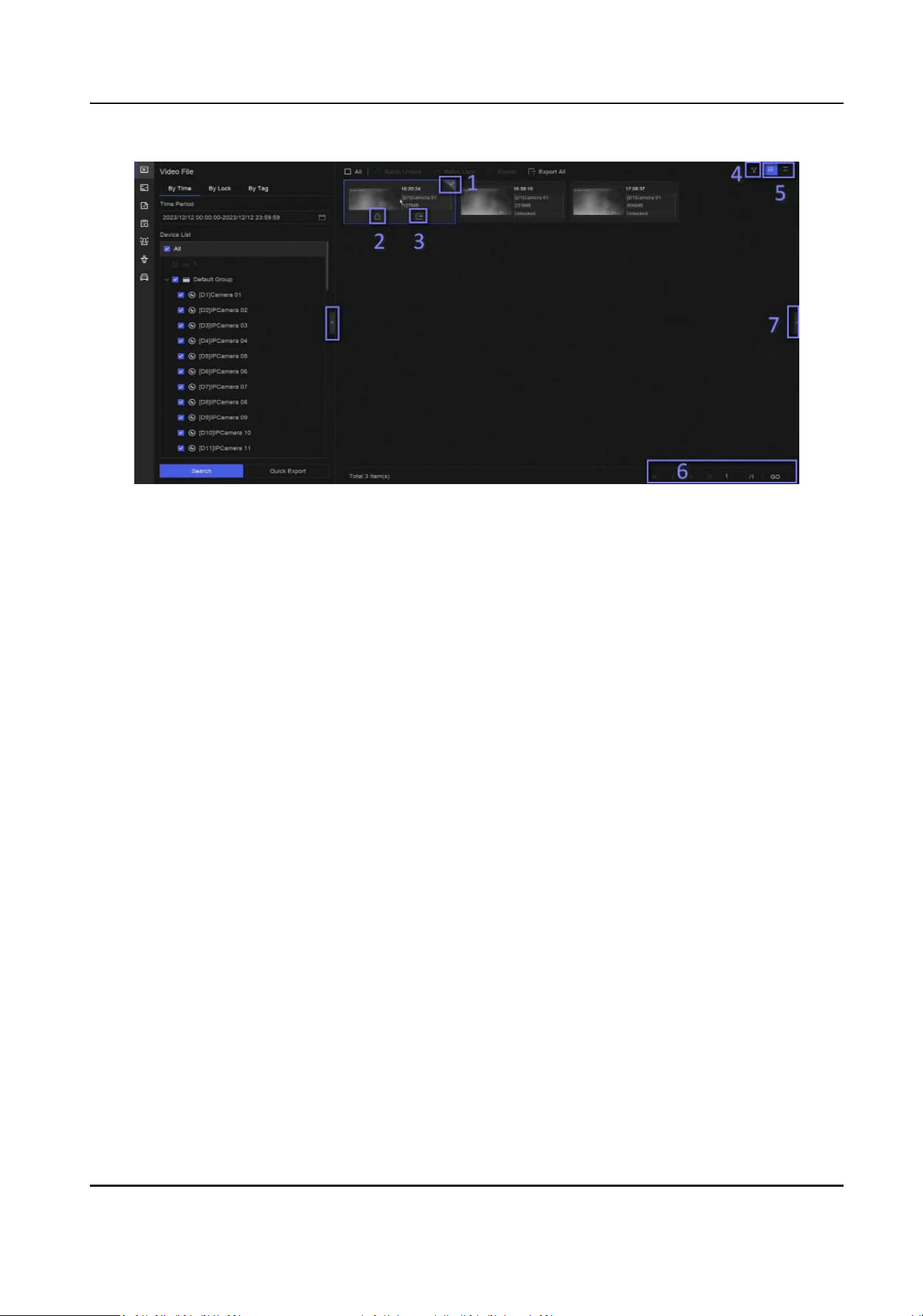
Figure 14-2 Searching Result
5.
Oponal: Perform the following operaons.
1 Click to select a le.
2 Click to lock a le. Aer a le is locked, it will not be overwrien.
3 Click to export a le.
4 Use the tool bar at the top to lter results by channel.
5 Use the tool bar at the top to switch display eect.
6 Go to dierent result pages.
7 Expand or collapse the interface. Aer selecng a video from the result list, you would be
able to quickly play it back.
6.
Insert a USB ash drive to the device for backup.
7.
Export
les to the USB ash drive.
-
Select
les(s) in the result list and click Export.
-
Click Export All to export all the
les.
Network Video Recorder User Manual
89
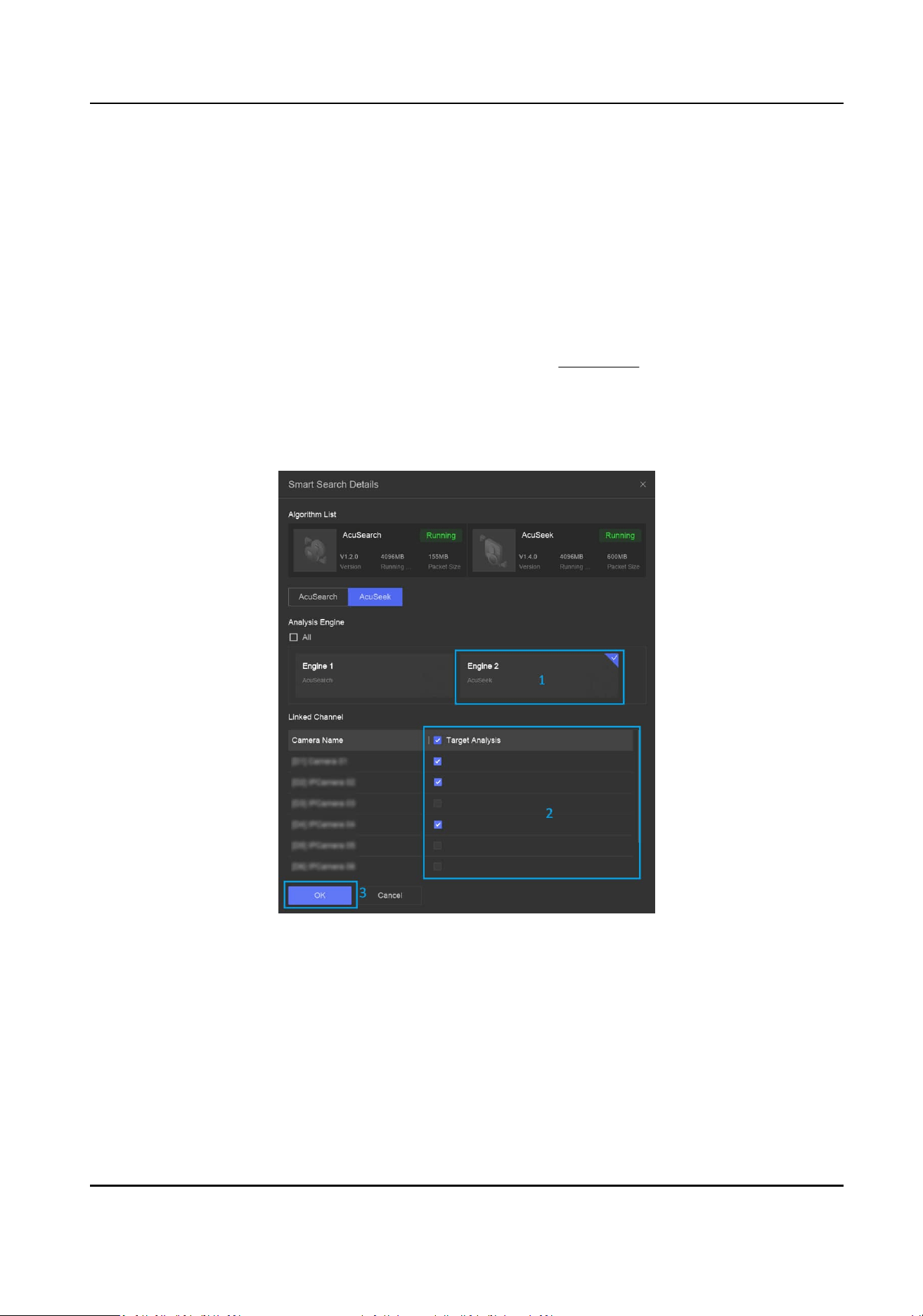
Chapter 15 AcuSeek
AcuSeek enables ecient and accurate retrieval of desired images and video clips by simply
entering relevant text
descripons.
Before You Start
●
Make sure you have added the camera which supports AcuSeek and
congured recording
schedule for the camera.
●
Make sure you have congured AcuSearch engine. Refer to AcuSearch .
Steps
1.
Go to Event Center → Event Conguraon → Smart Sengs → Algorithm Management →
Smart Search , select AcuSeek, and check target analysis for the corresponding channels.
Figure 15-1 Congure AcuSeek Engine
2.
On the GUI main page, click AcuSeek, and set condions according to actual needs.
Network Video Recorder User Manual
90

Figure 15-2 Set Search Condions
-
(Recommended) Click Suggesons, Person, Vehicle, or NMV, and select from the predened
condions.
When searching for persons and vehicles, you can select condions from mulple
aspects. For example, you can search for a person wearing a yellow top, a blue boom and a
hat.
-
Enter the condion in the search box.
-
Click Favorites to select
condions from Favorites.
You can click Custom to add terms to Favorites.
-
Click Today, and dene the me (3 Days, 7 Days, Custom) for searching.
-
Click a history search condion / an example term below the search box. You can click to
add a history search condion to Favorites.
3.
Click Search to view the searched results, and perform more
operaons according to the gure
below.
Network Video Recorder User Manual
91
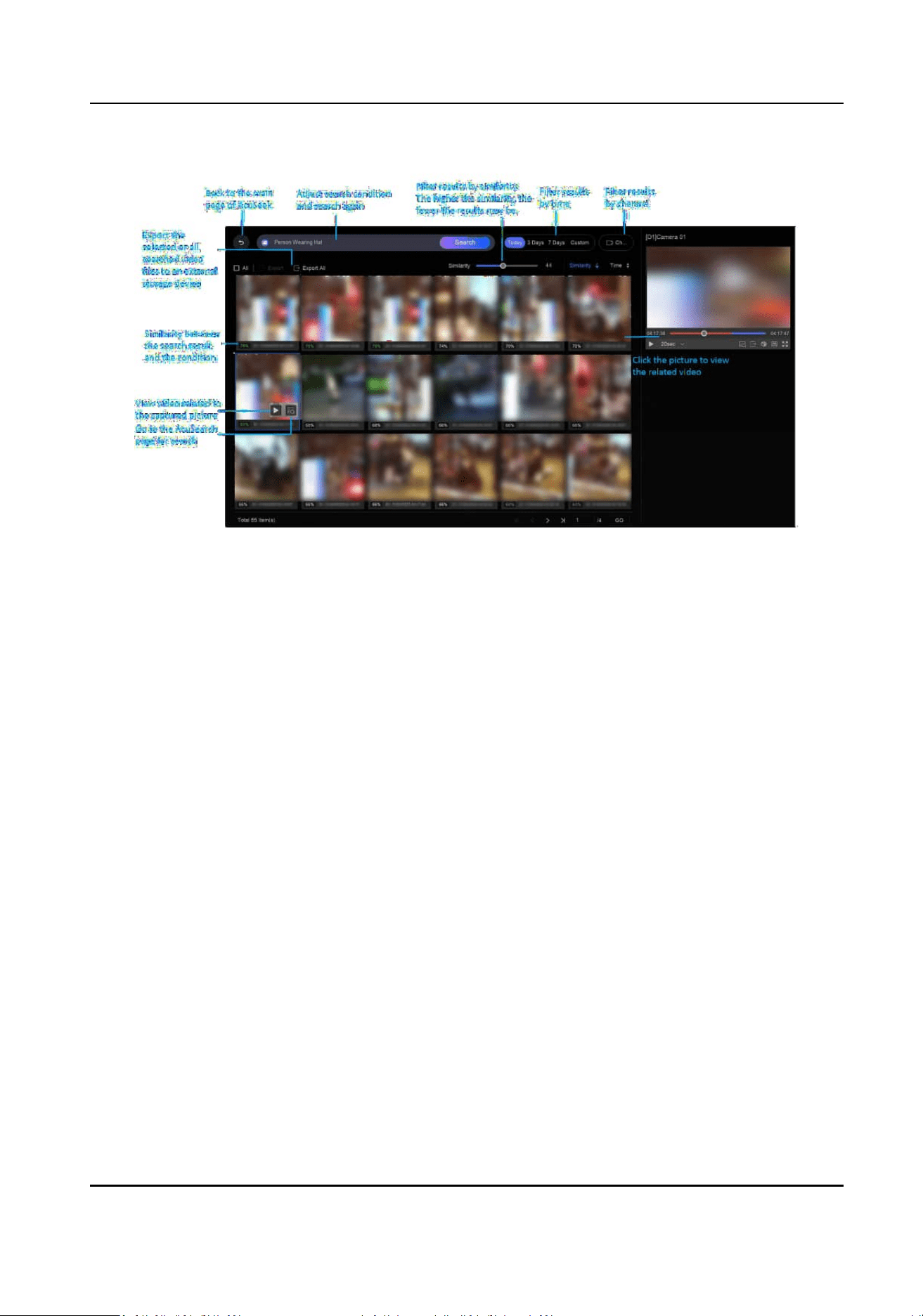
Figure 15-3 AcuSeek Results
Network Video Recorder User Manual
92

Chapter 16 AcuSearch
AcuSearch funcon rstly extracts pictures of human face or body from a video scene during live
view or playback, then compares the extracted picture with recorded videos, and eventually
nds
out videos that contains the target.
Before You Start
Ensure your device or camera supports this
funcon.
Steps
1.
Go to System → Smart Sengs → Algorithm Conguraon → Algorithm Management to
enable AcuSearch algorithm.
-
AI by Camera: The camera will perform the AcuSearch analysis.
-
AI by NVR: The device will perform the AcuSearch analysis, and engine resource is required
for analysis.
2.
Go to Live View or Playback, and click at the lower-le corner during video playing.
Note
●
If targets are hard to nd during playback, it is recommended to use Smart Search ( ) to
nd scenes that contain targets.
●
Human face and body would be framed with dierent colors.
●
Aer clicking , you can also drag the cursor on the image to manually frame a target, or
manually adjust the frame area.
3.
Click of the selected target.
Network Video Recorder User Manual
93
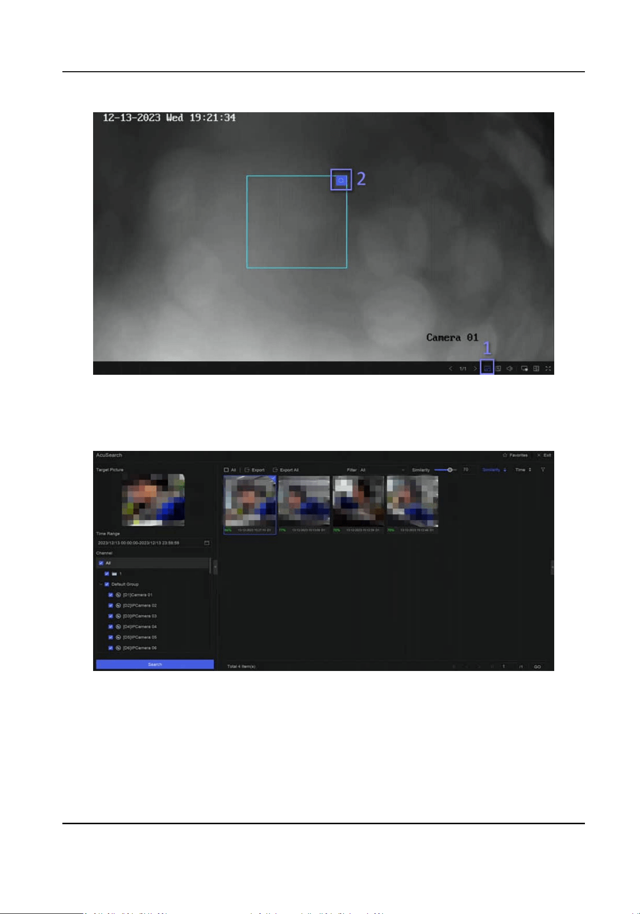
Figure 16-1 AcuSearch
If compared videos are found, the device will redirect to AcuSearch interface.
4.
View searching results.
Figure 16-2 AcuSearch Result
5.
Oponal: If the results are not desired, you can adjust parameters like Time Range, Channel, or
Similarity to search again.
6.
Oponal: Select an item from the result list, and its corresponding video would be played back
at the right side and be marked with red color. You can click the icons at the tool bar to perform
funcons.
Network Video Recorder User Manual
94

Chapter 17 Smart Sengs
17.1 Algorithm Management
Algorithms are used for device engines to analyze dierent smart funcons. Smart funcon would
be usable aer allocang the corresponding algorithm to an engine.
Go to System → Event Conguraon → Event Conguraon → Smart Sengs → Algorithm
Management or Event Center → Event Conguraon → Smart Sengs → Algorithm
Management. The available algorithms would be listed, and you can click the required algorithm to
link engine(s).
For certain models that support AcuSearch algorithm, you can choose the camera (AI by Camera)
or NVR (AI by NVR) to run AcuSearch algorithm.
17.2 Engine Status
You can view the engine status, including running status, temperature and algorithm name.
Go to System → Event Conguraon → Event Conguraon → Smart Sengs → Engine Status or
Event Center → Event Conguraon → Smart Sengs → Engine Status. If you need to switch the
algorithm, refer to
Algorithm Management .
17.3 Task Plan Management
You can view the task status in task conguraon. Smart analysis results are used for ltering the
pictures when searching interested human body and vehicle pictures.
Go to System → Event
Conguraon → Event Conguraon → Smart Sengs → Task Plan
Management or Event Center → Event Conguraon → Smart Sengs → Task Plan
Management. For Non-Real-Time Target Comparison, you can view the progress of each day.
Task status mainly includes 3
condions: Disabled, Waing, and Enabled.
Disabled
No analysis task is enabled on the camera.
Waing
The analysis task of the camera is enabled. Device is waing to analyze data.
Enabled
The analysis task of the camera is enabled and device is analyzing data of the camera.
Network Video Recorder User Manual
95

17.4 List library Management
List library is mainly used for target picture storage and target comparison. Strangers library is used
to store pictures for strangers, and it cannot be deleted.
17.4.1 Add a List Library
Steps
1.
Go to System → Event Conguraon → Event Conguraon → Data Archive → List Library or
Event Center → Event
Conguraon → Data Archive → List Library.
2.
Click Add.
3.
Enter the library name.
4.
Click
Conrm.
Note
●
Aer a list library, you can move the cursor on the library to edit or delete it.
●
You can click Delete in Batch to delete selected libraries, or clear all pictures in the selected
libraries.
17.4.2 Upload Face Pictures to the Library
Target picture comparison is based on target pictures in the library. You can upload a single target
picture or import mulple target pictures to the library.
Before You Start
●
Ensure the picture format is JPEG or JPG.
●
Import all pictures to a backup device in advance.
Steps
1.
Double click a list library.
2.
Oponal: Click Custom Tag to add tags to pictures. The tag can be edit as your desire, for
example, personal informaon, organizaon, posion, etc.
3.
Click Add or Import.
4.
Import picture(s).
-
Add: Click
to upload a picture at a me. If the picture has mulple targets, you have to
pick one from them.
-
Import: Mulple pictures can be imported at a me. The device will use the le name as its
picture name and leave other aributes empty, or import picture les by specied rules. If a
picture has
mulple targets in the image, the device will choose the target at the center by
default.
5.
Oponal: Perform the following operaons.
Network Video Recorder User Manual
96

Delete Pictures from
the Library
●
Select a picture and delete it.
●
Select pictures and click Delete in Batch to delete the select
ones.
Search Pictures in the
Library
Click at the tool bar to search pictures.
Copy Pictures to
Another Library
Select pictures and click Copy to to copy the uploaded pictures of
the current library to another library.
Edit Pictures Click the picture name, and edit its aributes.
Export Pictures Select pictures, and click Export to export them to a USB ash
drive.
17.5 Self-Learning Sengs
Self-learning technology opmizes algorithm accuracy and requires minimum manual intervenon
from users. When self-learning funcon is enabled, the device would automacally collect false
alarm materials, and use the collected materials to constantly train and opmize the
corresponding algorithm.
Go to System → Event
Conguraon → Event Conguraon → Smart Sengs → Algorithm
Management or Event Center → Event
Conguraon → Smart Sengs → Algorithm
Management to enable Self-Learning algorithm.
Note
●
Only certain models support this funcon.
●
Currently, self-learning funcon can only be adopted for perimeter protecon events.
●
If your device only has one engine, AI by NVR has to be disabled and the camera should perform
the analysis of
detecon targets. If your device only has two or more engines, you can enable AI
by NVR and use one engine for the analysis of
detecon targets, then use another engine to run
the self-learning algorithm.
17.5.1 Self-Learning Task Management
Aer self-learning algorithm is running, the self-learning task should be enabled as well.
Go to System → Event
Conguraon → Event Conguraon → Self-Learning → Task Management
or Event Center → Event Conguraon → Self-Learning → Task Management to enable the task.
The available task would be listed, and you can view task status and progress bar. It would take a
long
me for the material collecon.
When the task is completed, self-learning algorithm would be updated automacally. You can click
Auto Update Cong to set Update Time.
Network Video Recorder User Manual
97

Note
●
When the self-learning algorithm would be unavailable for perimeter protecon events when
the algorithm is updang.
●
Force Training is only used for the technical support.
17.5.2 Model Management
You can set the self-learning algorithm model version according to your requirement.
Go to System → Event Conguraon → Event Conguraon → Self-Learning → Model
Management or Event Center → Event
Conguraon → Self-Learning → Model Management to
set the model version.
Restore to Previous Version
Restore the model to the version before this one.
Restore to Default Version
Restore the model to the factory default version.
17.5.3 Smart Status
You can view the self-learning algorithm performance status of each channel in System → Event
Conguraon → Event Conguraon → Self-Learning → Smart Status or Event Center → Event
Conguraon → Self-Learning → Smart Status.
Network Video Recorder User Manual
98
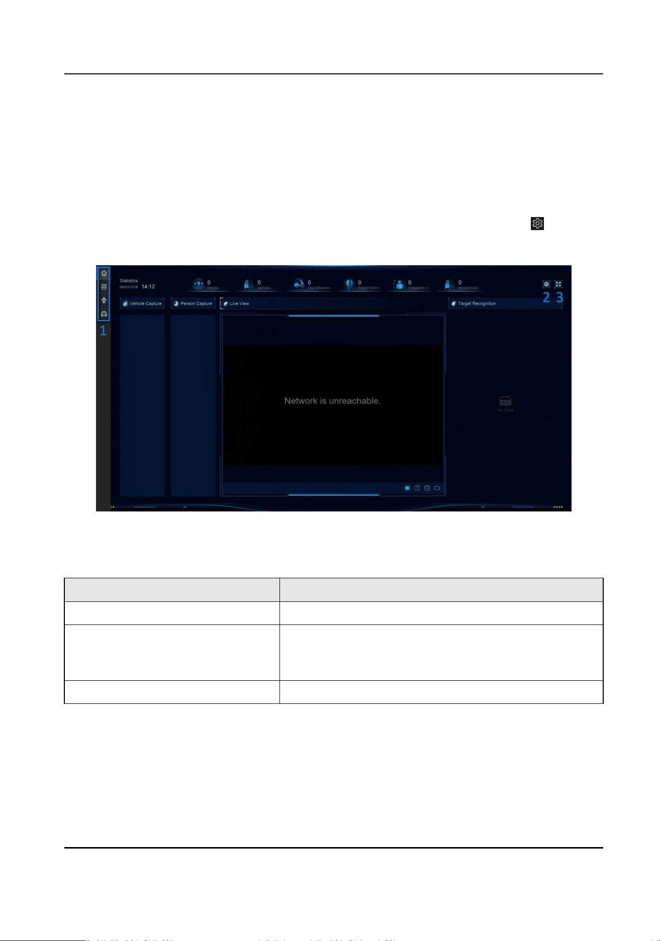
Chapter 18 Applicaon Center
18.1 Human and Vehicle Detecon
The human and vehicle informaon will be displayed for the selected channel at real-me.
Human and vehicle detecon should be congured in advance. Go to Event Center → to
congure.
Figure 18-1 Human and Vehicle Detecon
Table 18-1 Human and Vehicle Detecon Descripon
No. Descripon
1 Right-click shortcut menu.
2 Human and vehicle detecon sengs. You can set the
layout, comparison succeeded prompt, and resource
channels.
3 Enter/exit full screen.
18.2 Person Check-In
Aer check-in tasks are added, you can view the live check-in informaon and search check-in
results.
Network Video Recorder User Manual
99

18.2.1 Add Check-In Task
Before starng person check-in, the corresponding task should be properly congured.
Before You Start
●
A camera for person check-in is properly connected.
●
Go to System → Smart
Sengs → Algorithm Conguraon → Algorithm Management .
Allocate Target Recognion to at least one engine.
●
The list library for check-in comparison is properly congured. Refer to Add a List Library for
details.
Steps
1.
Click Person Check-In .
2.
Right click to display the menu at
le side.
3.
Click .
4.
Click Add.
Figure 18-2 Add Check-In Task
5.
Set Task.
One-Time
The task will be used for one
me.
Repeat
The task will be used and repeated for several mes.
6.
Congure other parameters, including Task Name, Check-In Time, Recognion Channel, etc.
7.
Click Conrm.
Network Video Recorder User Manual
100
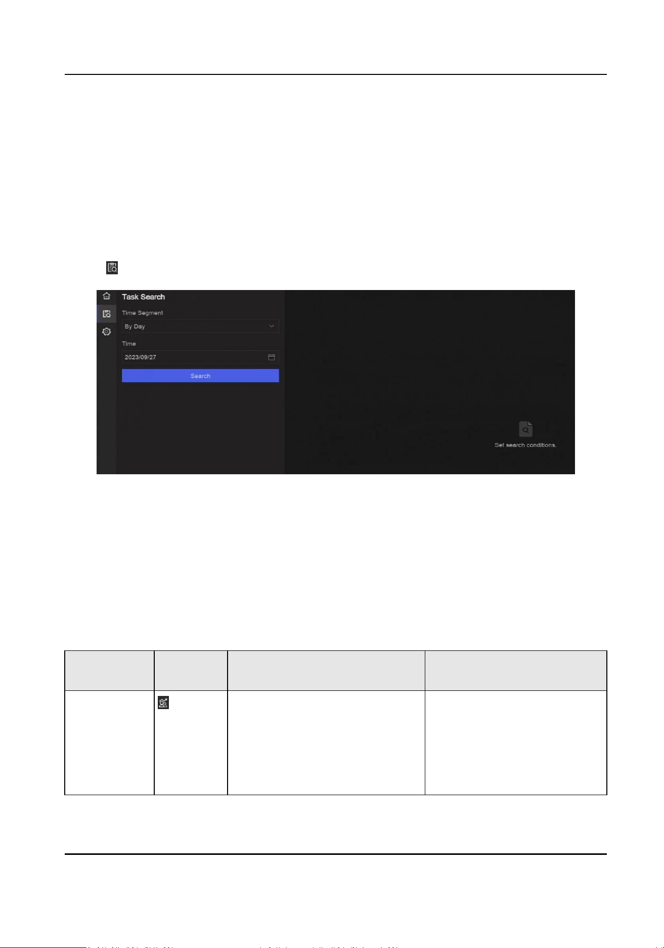
18.2.2 Search Check-In Records
Aer check-in tasks are congured, you can search the records by day or month.
Before You Start
Ensure check-in tasks are congured.
Steps
1.
Go to Person Check-In .
2.
Right click to display the menu at the
le side.
3.
Click
.
Figure 18-3 Search Check-In Records
4.
Set me.
5.
Click Search.
18.3
Stasc Report
You can view reports of people counng and heat map.
Table 18-2
Stasc Report Introducon
Funcon
Name
Icon Condion Descripon
People
Counng
●
The funcon must be supported
by the connected IP camera. For
example, a people counng
People counng calculates the
number of people entering or
leaving a certain congured
area and creates daily/weekly/
monthly/annual reports for
analysis.
Network Video Recorder User Manual
101

Funcon
Name
Icon Condion Descripon
camera is connected to your
device.
●
Camera stasc data can be
stored to the device HDD.
Heat Map
●
The funcon must be supported
by the connected IP camera.
●
Camera stasc data can be
stored to the device HDD.
Heat map is a graphical
representaon of data. The
heat map funcon is used to
analyze how many people
visited and stayed in a specic
area.
Network Video Recorder User Manual
102

Chapter 19 System Parameter Sengs
System parameters include device name, region, me, lock screen me, language, etc.
Go to System → System
Sengs → System Conguraon to congure parameter.
Table 19-1 Parameter Descripon
Type Parameter Name Descripon
Basic Info Lock Screen Time The screen would be locked when the cursor is not
moving for the specied me.
Live View
Permission on
Lock Screen
Aer the screen is locked, the device would play the live
image of cameras that have this permission.
Region & Time
Conguraon
Time Zone Lock The admin password is required for this operaon. Aer
Time Zone is locked, the device me zone informaon
cannot be remotely changed from other plaorms or
interfaces, such as the web interface via web browser.
You can only lock or unlock Time Zone through local GUI
interface.
Time Sync Mode
●
NTP Time Sync: You can select NTP Time Sync and
congure NTP Server, NTP Server Port, NTP Client
Port, and Interval. Interval is the me interval
between two synchronizing
acons within the NTP
server. If the device is connected to a public network,
you should use a NTP server that has a me
synchronizaon funcon, such as the listed server
addresses for selecon. If the device is set in a
customized network, NTP
soware can be used to
establish a NTP server for me synchronizaon.
●
Manual Time Sync: Manually set the system me.
●
Hik-Connect Server Time Sync: The device will sync
me with Hik-Connect instead of NTP server.
●
Guarding Vision Server Time Sync:The device will sync
me with Guarding Vision instead of NTP server.
DST DST (daylight saving me) refers to the period of the
year when clocks are moved one period ahead. In some
areas worldwide, this has the eect of creang more
sunlit hours in the evening during months when the
weather is the warmest.
Network Video Recorder User Manual
103

Type Parameter Name Descripon
We advance our clocks ahead a certain period (depends
on the DST bias you set) at the beginning of DST, and
move them back the same period when we return to
standard
me (ST).
Menu Output Auxiliary Port
Auto-Switch
When two or more monitors are connected to rear
panel, one of the them may become the auxiliary output
that cannot enter main menu. Images at the auxiliary
output windows will be
automacally switched to next
ones according to the interval.
Channel-Zero - Channel-zero, known as virtual channel, can show live
images of all channels of the device, which saves
bandwidth for transmission.
RS-232 Usage Console
Aer connecng it to PC with a convertor, PC can set
the device parameters.
Transparent Channel
It is directly connected to a serial device. PC can
remotely access the serial device through network.
Network Video Recorder User Manual
104
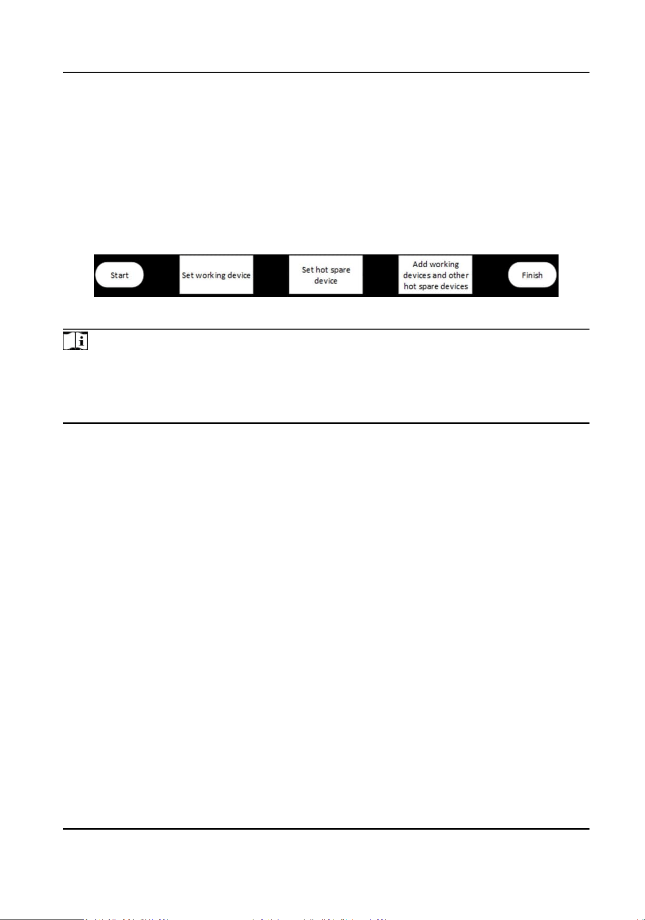
Chapter 20 Hot Spare Device Backup
Video recorders can form an N+M hot spare system. The system consists of several working video
recorders and at least one hot spare video recorder. When a working video recorder fails, the hot
spare video recorder would switch into
operaon, which increases the reliability of the system. A
bidireconal connecon shown in the gure below is required to be built between hot spare video
recorder(s) and working video recorders.
Figure 20-1 Build a Hot Spare System
Note
●
Up to 32 working devices and 32 hot spare devices are allowed.
●
It is recommended to use all devices in a same model for compability. Contact your dealer for
details of models that support the hot spare funcon.
●
Only certain models support this
funcon.
20.1 Set Working Device
Steps
1.
Go to System → System Management → N+M Hot Spare .
2.
Set Working Mode as Normal Mode.
3.
Turn on Enable.
4.
Click Save.
5.
Oponal: View Hot Spare Device IP Address and Hot Spare Device Working Status.
20.2 Set Hot Spare Device
Hot spare device will take over working device tasks when working device fails.
Steps
1.
Go to System → System Management → N+M Hot Spare .
2.
Set Working Mode as Hot Spare Mode.
3.
Click Save. Your device will restart
automacally.
Network Video Recorder User Manual
105

Note
●
The camera connecon will be disabled when the device works in hot spare mode.
●
It is highly recommended to restore the device defaults aer switching the work mode of hot
spare devices to normal mode to ensure the normal operaon aerwards.
4.
Go to System → System Management → N+M Hot Spare again.
5.
Add working devices to the hot spare system.
6.
Add hot spare devices to the hot spare system.
7.
Click Save.
Network Video Recorder User Manual
106
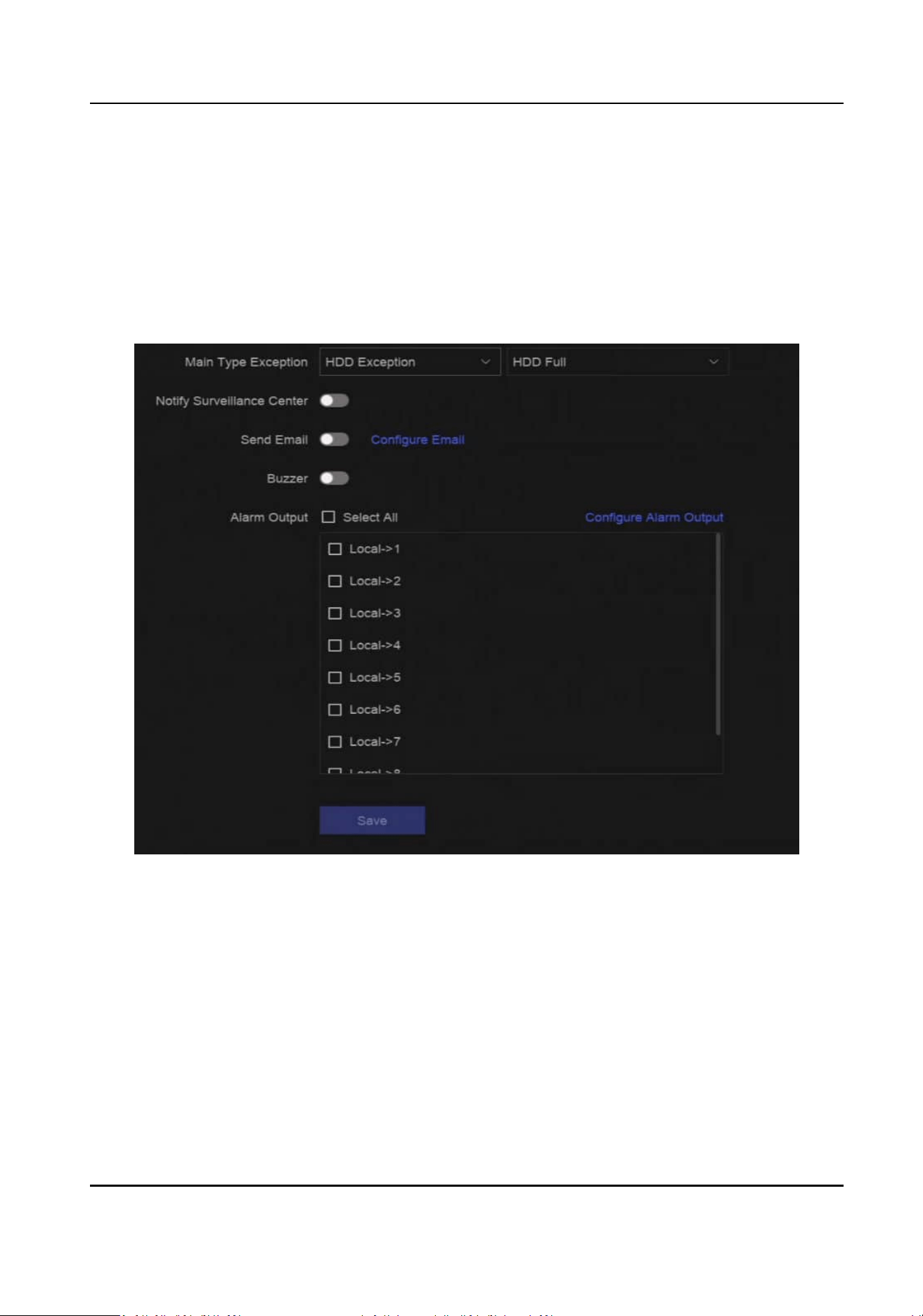
Chapter 21 Congure Excepon Event
Excepon events can be congured to take the event hint in the live view interface and trigger
alarm output and linkage
acons.
Steps
1.
Go to System → System Sengs → Excepon .
Figure 21-1 Excepon Event Conguraon
2.
Select excepon type.
3.
Congure the linkage methods.
Network Video Recorder User Manual
107

Table 21-1 Linkage Descripon
Linkage Method Descripon
Nofy Surveillance
Center
The device can send an excepon or alarm signal to the remote
alarm host when an event occurs. The alarm host refers to the PC
installed with client soware (e.g., iVMS-4200, iVMS-5200).
Buzzer When an alarm is detected, the buzzer will make an audible beep.
Send Email The system can send an email with alarm informaon to a user or
users when an alarm is detected.
Alarm Output The alarm output can be triggered by the alarm input, moon
detecon, video tampering detecon, face detecon, line crossing
detecon, and any all other events.
Note
When excepon events occur, at the upper-right corner would nofy, and you can click to
view.
4.
Click Save.
Network Video Recorder User Manual
108

Chapter 22 View System Info
Go to System → System Maintenance → Running Info → System Info to view the system
informaon, including video recording informaon, HDD informaon, network informaon, stream
informaon of live view or video playback, me sync diagnosis informaon, etc.
If device excepon occurs, for example, when me sync excepon occurs and the RTC (coin/buon
cell) baery is out of power, it may aect the video recording or playback, please resolve the
excepon as soon as possible.
Network Video Recorder User Manual
109

Chapter 23 System Maintenance
System maintenance funcons include log search, schedule reboot, upgrade, etc.
23.1 Schedule Reboot
The device will automacally restart according to the schedule.
Go to System → System Maintenance → Maintenance → Schedule Reboot to enable the
funcon,
and set the reboot schedule.
23.2 Upgrade Device
The device system can be upgraded with a local USB ash drive, remote FTP server, etc.
Go to System → System Maintenance → Maintenance → Upgrade to upgrade your device.
23.3 Backup and Restore
Go to System → System Maintenance → Maintenance → Backup and Restore to restore or back
up system parameters.
Import/Export
Conguraon File
The device conguraon les can be exported to a local device for backup, and the
conguraon les of one device can be imported to mulple devices if they are to be congured
with the same parameters.
Simple Restore
Restore all parameters, except the network (including IP address, subnet mask, gateway, MTU,
NIC working mode, default route, server port, etc.) and user account parameters, to the factory
default
sengs.
Factory Defaults
Restore all parameters to the factory default sengs.
Restore to Inacve
Restore the device to the inacve status, and leave all sengs unchanged except restoring user
accounts.
Network Video Recorder User Manual
110

23.4 Log Info
Go to System → System Maintenance → Maintenance → Log to search and export log
informaon.
Expired Time Sengs
When the log disk is full, logs that exceed the period will be overwrien.
23.5 Congure Log Server
You can upload system logs to the server for backup.
Steps
1.
Go to System → CX → System Sengs → Network → Network → Log Server .
2.
Turn on Enable.
3.
Set Upload Time, Server IP Address, and Port.
4.
Oponal: Click Test to test if parameters are valid.
5.
Click Save.
23.6 Maintenance Tools
Mulple tools are provided for system maintenance, such as S. M. A. R. T. detecon and bad sector
detecon.
Before You Start
Ensure HDD is properly installed.
Steps
1.
Go to System → System Maintenance → Maintenance → Maintenance Tools .
2.
Select tools according to your requirement.
Table 23-1 Tool
Descripon
Tool Name Descripon
Network Data
Monitoring
Network data monitoring is the process of reviewing, analyzing and
managing network data for any abnormality or process that can
aect network performance, availability, or security.
Network Packet Capture Ping
The ping test is used to detect whether the desnaon IP address
is reachable.
NIC Packet Capture
Network Video Recorder User Manual
111
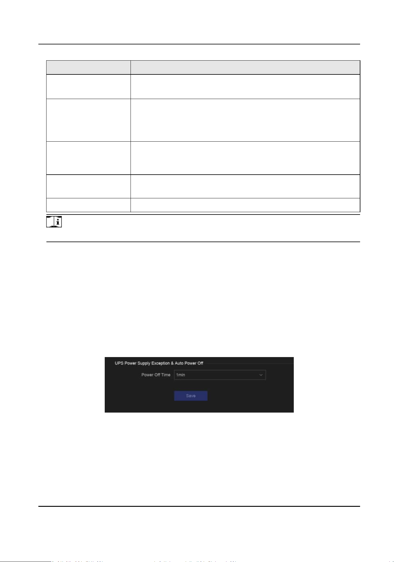
Tool Name Descripon
Aer the recorder accessing network, you can use USB ash drive
to capture and export network packet.
HDD Status Detecon You can view the health status of a 4 TB to 8 TB Seagate HDD that
generated aer October 1, 2017. Use this funcon to help
troubleshoot HDD problems. Health Detecon shows a more
detailed HDD status than the S.M.A.R.T.
funcon.
S.M.A.R.T. Detecon S.M.A.R.T. (Self-Monitoring, Analysis, and Reporng Technology) are
HDD monitoring systems to detect various reliability indicators in the
hopes of ancipang failures.
Bad Sector Detecon When an HDD contains too many bad sectors, it is recommended to
replaced the HDD, otherwise les in the HDD may be lost.
HDD Clone Cope the data in HDD to another one through eSATA interface.
Note
It is recommended to use maintenance tools with the help of technical support.
23.7 So Power O Conguraon
So power o funcon is only available for devices with POWER-AC (AC power excepon), POWER-
UPS (UPS excepoin), and POWER-UPSL (UPS low power) alarm outputs (at the real panel). The
device can receive and record these alarms. When both POWER-AC and POWER-UPSL alarms are
triggered, the device will
automacally be powered o according to the preset me. When either
POWER-AC or POWER-UPSL alarm is not triggered, the device will
automacally be powered on.
Steps
1.
Go to System → System Maintenance → Maintenance → So Power O Conguraon.
Figure 23-1
So Power O Conguraon
2.
Set Power O Time. The device would automacally power o aer the preset me when
corresponding alarms are triggered.
3.
Click Save.
Network Video Recorder User Manual
112

Example
For example, if Power O Time is set as 1min, when both POWER-AC (AC power excepon) and
POWER-UPSL (UPS low power) alarms are triggered, the device would automacally power o
aer
1 minute.
Network Video Recorder User Manual
113

Chapter 24 Security Management
24.1 Address Filter
The address lter decides whether to allow or forbid specic IP/MAC address to get access to your
device.
Before You Start
Log in with the admin account.
Steps
1.
Go to System → System Maintenance → Security Management → Address Filter .
2.
Turn on Enable.
3.
Set Filtering Type. Choose to
lter by IP address or MAC Address.
4.
Set
Restricon Type. The device mechanism will allow or forbid specic IP/MAC address to get
access to your device.
5.
Oponal: Set Restricon List. You can add, edit or delete address.
6.
Click Save.
24.2 Stream
Encrypon
Aer enabling stream encrypon, encrypon key would be required for remote live view, remote
playback, and the downloaded videos.
Steps
1.
Go to System → System Maintenance → Security Management → Stream Encrypon .
2.
Turn on Enable.
3.
Set
Encrypon Key.
Note
The stream encrypon key is synchronized with the Hik-Connect service vericaon code. Aer
enabling the encrypon code, the Hik-Connect stream will be forcedly encrypted.
4.
Click Save.
24.3 Select TLS Version
TLS
sengs will be eecve for HTTP(s) and enhanced SDK service. It provides more secure stream
transmission service. Go to System → System Maintenance → Security Management → TLS to
select TLS version.
Network Video Recorder User Manual
114

Chapter 25 Appendix
25.1 List of Applicable Power Adapter
Only use power adapters listed below.
Power Adapter Model Specicaons Manufacturer
ADS-26FSG-12 12024EPG 12 V, 2 A Shenzhen Honor Electronic Co.,
Ltd.
MSA-Z3330IC12.0-48W-Q 12 V, 3.33 A Moso Power Supply Technology
Co., Ltd.
MSA-C1500IC12.0-18P-DE 12 V, 1.5 A 0000201935 MOSO Technology
Co., Ltd.
ADS-25FSG-12 12018GPG CE, 100 to 240 VAC, 12 V, 1.5 A,
18 W, Φ5.5 × 2.1 × 10
0000200174 Shenzhen Honor
Electronic Co., Ltd.
MSA-C1500IC12.0-18P-US 12 V, 1.5 A 0000201935 MOSO Technology
Co., Ltd.
TS-A018-120015AD 100 to 240 VAC, 12 V, 1.5 A, 18
W, Φ5.5 × 2.1 × 10
0000200878 Shenzhen Transin
Technologies Co., Ltd.
MSA-C2000IC12.0-24P-DE 12 V, 2 A 0000201935 MOSO Technology
Co., Ltd.
ADS-24S-12 1224GPG CE, 100 to 240 VAC, 12 V, 2 A,
24 W, Φ2.1
0000200174 Shenzhen Honor
Electronic Co., Ltd.
MSA-C2000IC12.0-24P-US US, 12 V, 2 A 0000201935 MOSO Technology
Co., Ltd.
ADS-26FSG-12 12024EPCU US, 12 V, 2 A 0000200174 Shenzhen Honor
Electronic Co., Ltd.
KPL-040F-VI 12 V, 3.33 A, 40 W 0000203078 Channel Well
Technology Co., Ltd.
MSA-Z3330IC12.0-48W-Q 12 V, 3.33 A 0000201935 MOSO Technology
Co., Ltd.
MSP-Z1360IC48.0-65W 48 V, 1.36 A 0000201935 MOSO Technology
Co., Ltd.
KPL-050S-II 48 V, 1.04 A 0000203078 Channel Well
Technology Co., Ltd.
Network Video Recorder User Manual
115

25.2 Glossary
Dual-Stream
Dual-stream is a technology used to record high resoluon video locally while transming a
lower resoluon stream over the network. The two streams are generated by the DVR, with the
main stream having a maximum
resoluon of 1080P and the sub-stream having a maximum
resoluon of CIF.
DVR
Acronym for Digital Video Recorder. A DVR is device that is able to accept video signals from
analog cameras, compress the signal and store it on its hard drives.
HDD
Acronym for Hard Disk Drive. A storage medium which stores digitally encoded data on plaers
with magnec surfaces.
DHCP
Dynamic Host Conguraon Protocol (DHCP) is a network applicaon protocol used by devices
(DHCP clients) to obtain conguraon informaon for operaon in an Internet Protocol
network.
HTTP
Acronym for Hypertext Transfer Protocol. A protocol to transfer hypertext request and
informaon between servers and browsers over a network.
PPPoE
PPPoE, Point-to-Point Protocol over Ethernet, is a network protocol for encapsulang Point-to-
Point Protocol (PPP) frames inside Ethernet frames. It is used mainly with ADSL services where
individual users connect to the ADSL transceiver (modem) over Ethernet and in plain Metro
Ethernet networks.
DDNS
Dynamic DNS is a method, protocol, or network service that provides the capability for a
networked device, such as a router or computer system using the Internet Protocol Suite, to
nofy a domain name server to change, in real me (ad-hoc) the acve DNS conguraon of its
congured hostnames, addresses or other informaon stored in DNS.
Hybrid DVR
A hybrid DVR is a combinaon of a DVR and NVR.
NTP
Acronym for Network Time Protocol. A protocol designed to synchronize the clocks of
computers over a network.
NTSC
Network Video Recorder User Manual
116

Acronym for Naonal Television System Commiee. NTSC is an analog television standard used
in such countries as the United States and Japan. Each frame of an NTSC signal contains 525
scan lines at 60Hz.
NVR
Acronym for Network Video Recorder. An NVR can be a PC-based or embedded system used for
centralized management and storage for IP cameras, IP Domes and other DVRs.
PAL
Acronym for Phase
Alternang Line. PAL is also another video standard used in broadcast
televisions systems in large parts of the world. PAL signal contains 625 scan lines at 50Hz.
PTZ
Acronym for Pan, Tilt, Zoom. PTZ cameras are motor driven systems that allow the camera to
pan
le and right, lt up and down and zoom in and out.
USB
Acronym for Universal Serial Bus. USB is a plug-and-play serial bus standard to interface devices
to a host computer.
25.3 Frequently Asked
Quesons
25.3.1 Why is there a part of channels displaying “No Resource” or turning black
screen in mul-screen live view?
Reason
1. Sub-stream resoluon or bitrate sengs is inappropriate.
2. Connecng sub-stream failed.
Soluon
1. Go to Camera → Video Parameters → Sub-Stream . Select the channel, and turn down the
resoluon and max. bitrate (resoluon shall be less than 720p, max. bitrate shall be less than
2048 Kbps).
Note
If your video recorder noes not support this funcon, you can log in to the camera, and
adjust video parameters via web browser.
2. Properly set the sub-stream resoluon and max. bitrate (resoluon shall be less than 720p, max.
bitrate shall be less than 2048 Kbps), then delete the channel and add it back again.
Network Video Recorder User Manual
117

25.3.2 Why is the video recorder nofying risky password aer a network camera
is added?
Reason
The camera password is too weak.
Soluon
Change the camera password.
Warning
We highly recommend you create a strong password of your own choosing (Using a minimum of 8
characters, including at least three of the following categories: upper case leers, lower case
leers, numbers, and special characters.) in order to increase the security of your product. And we
recommend you reset your password regularly, especially in the high security system,
reseng the
password monthly or weekly can
beer protect your product.
25.3.3 Why is the video recorder nofying the stream type is not supported?
Reason
The camera encoding format mismatches with the video recorder.
Soluon
If the camera is using H.265/MJPEG for encoding, but video recorder does not support H.265/
MJPEG, change the camera encoding format to the same as video recorder.
25.3.4 How to
conrm the video recorder is using H.265 to record video?
Soluon
Check if the encoding type at live view toolbar is H.265.
25.3.5 Why is the video recorder
nofying IP conict?
Reason
The video recorder uses the same IP address as other devices.
Soluon
Change the IP address of video recorder. Ensure it is not the same as other devices.
Network Video Recorder User Manual
118

25.3.6 Why is image geng stuck when playing back by single or mul-channel
cameras?
Reason
HDD read/write excepon.
Soluon
Export the video, and play it with other devices. If it plays normally on other device, change your
HDD, and try again.
25.3.7 Why is the device not able to control PTZ camera via coaxitron?
Reason
1. The camera does not support coaxitron.
2. The coaxitron protocol is incorrect.
3. The signal is
aected by video opcal transceiver.
Soluon
1. Ensure the video input signal is HDTVI, and the camera supports coaxitron.
2. Ensure coaxitron protocol parameters are correct, such as baud rate and address.
3. Remove the video
opcal transceiver, and try again.
25.3.8 Why does the PTZ seem unresponsive via RS-485?
Reason
1. The RS-485 cable is not properly connected.
2. The RS-485 interface is broken.
3. The control protocol is not correct.
Soluon
1. Check if RS-485 cable is properly connected.
2. Change RS-485 interface, and try again.
3. Ensure control protocol is Pelco.
25.3.9 Why is the video sound quality not good?
Network Video Recorder User Manual
119

Reason
1. The audio input device does not have a good eect in sound collecon.
2. Interference in transmission.
3. The audio parameter is not properly set.
Soluon
1. Check if the audio input device is working properly. You can change another audio input device,
and try again.
2. Check the audio transmission line. Ensure all lines are well connected or welded, and there is no
electromagnec interference.
3. Adjust the audio volume according to the environment and audio input device.
25.4
Nocaon for Corrosive Gas
In non-data center room, the corrosive gas concentraon limit is recommended to meet the
requirements of the chemical
acve substance 3C2 level in IEC 60721-3-3:2002.
Table 25-1 Corrosive Gas Concentraon Limit
Corrosive Gas Category Average Value (mg/m
3
) Max. Value (mg/m
3
)
SO
2
(Sulfur Dioxide) 0.3 1.0
H
2
S (Hydrogen Sulde) 0.1 0.5
Cl
2
(Chlorine) 0.1 0.3
HCl (Hydrogen Chloride) 0.1 0.5
HF (Hydrogen Fluoride) 0.01 0.03
NH
3
(Ammonia) 1.0 3.0
O
3
(Ozone) 0.05 0.1
NO
X
(Nitrogen Oxides) 0.5 1.0
Note
●
The average values in the table above are typical control limits for corrosive gases in the machine
room environment. In general, it is not recommended that the concentraon of corrosive gases
exceed the average value.
●
The maximum value refers to the limit or peak value. The
duraon for the corrosive gas
concentraon to reach the maximum value should not exceed 30 minutes per day.
Network Video Recorder User Manual
120

Table 25-2 Common Categories and Sources of Corrosive Gases
Category Primary Sources
H
2
S (Hydrogen Sulde) Geothermal emissions, microbial acvity, oil manufacturing,
wood corrosion, wastewater treatment, etc.
SO
2
(Sulfur Dioxide), SO
3
(Sulfur
Trioxide)
Coal combuson, petroleum products, automobile exhaust,
smelng ore, sulfuric acid manufacturing, tobacco combuson,
etc.
S (Sulfur) Foundry shops, sulfur manufacturing, etc.
HF (Hydrogen Fluoride) Ferlizer manufacturing, aluminum manufacturing, ceramic
manufacturing, steel manufacturing, electronic equipment
manufacturing, mineral combuson, etc.
NO
X
(Nitrogen Oxides) Automobile exhaust, oil combuson, microbial acvity, chemical
industry, etc.
NH
3
(Ammonia) Microbial acvity, sewage, ferlizer manufacturing, geothermal
emissions, etc.
CO (Carbon Monoxide) Combuson, automobile exhaust, microbial acvity, tree decay,
etc.
Cl
2
(Chlorine), ClO
2
(Chlorine
Dioxide)
Chlorine manufacturing, aluminum manufacturing, zinc
manufacturing, waste decomposion, etc.
HCl (Hydrogen Chloride) Automobile exhaust, combuson, forest res, marine process
polymer combuson, etc.
HBr (Hydrobromic Acid), HI
(Hydroiodic Acid)
Automobile exhaust, etc.
O
3
(Ozone) Atmospheric opcal processes (mostly including nitric oxide and
hydrogen peroxide), etc.
C
n
H
n
(Alkane) Automobile exhaust, tobacco burning, animal waste, sewage,
tree decay, etc.
Network Video Recorder User Manual
121

UD43002B