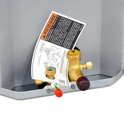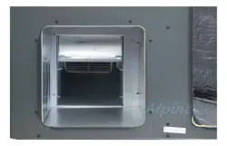
4. Locate heater box. Remove the two screws holding the heater
box cover in place. See Figure 1.
Figure 1
5. Remove the two screws holding the rear mounting plate. Note
the orientation of the heater box covers for reassembly.
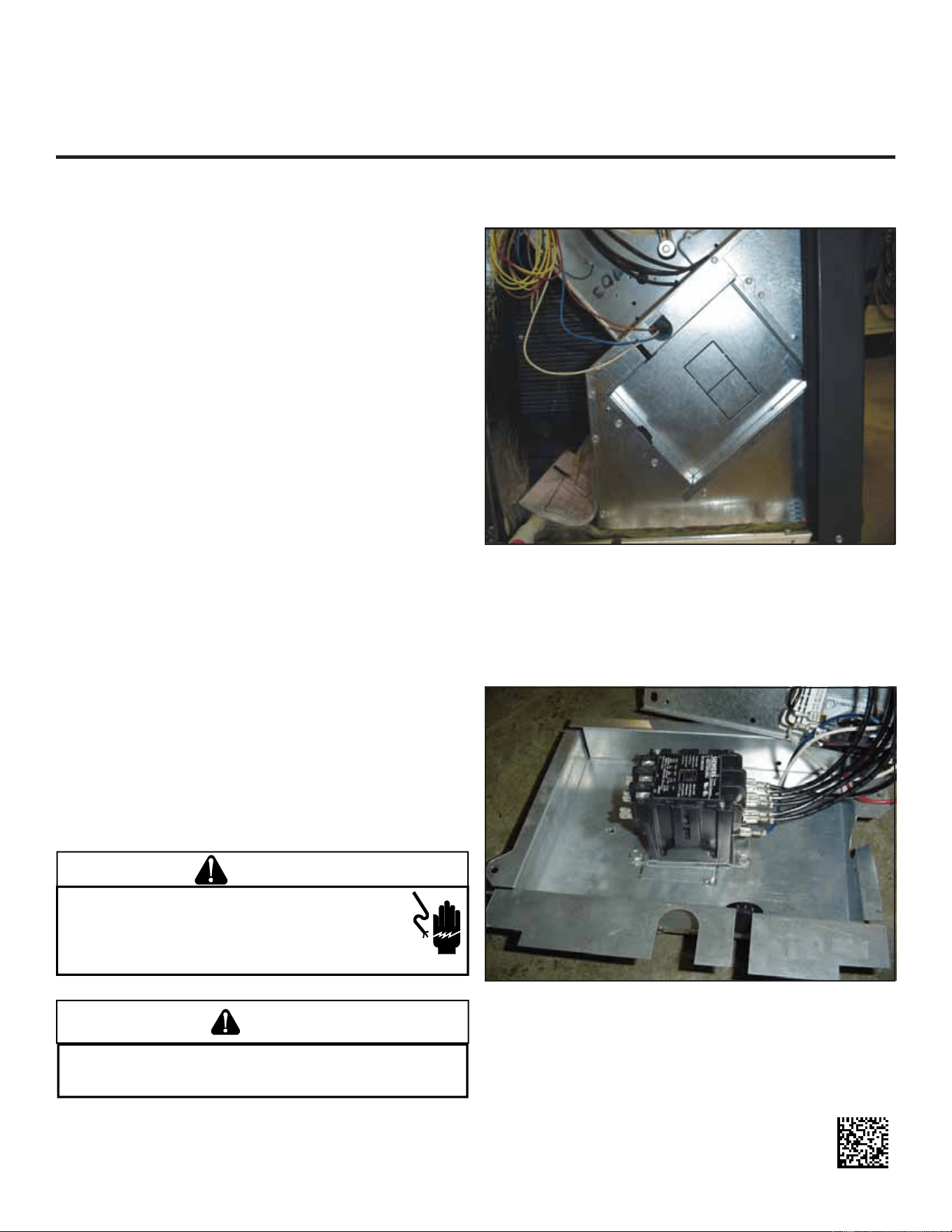
6. For three phase HKR kits only, remove the contactor from the
HKR mounting bracket, leaving the wires connected. Attach
contactor to rear mounting plate as shown in Figure 2.
Figure 2
7. Install heater element(s) with the 4 pointed screws included
in the unit literature bag. Note the air flow direction label lo-
cated on the heater element base shown in Figure 3. Orien-
tate the heating element base to match airflow direction on
package unit blower assembly.
Attention Installing Personnel
As a professional installer, you have an obligation to know the
product better than the customer. This includes all safety precau-
tions and related items.
Prior to actual installation, thoroughly familiarize yourself with this
Instruction Manual. Pay special attention to all safety warnings.
Often during installation or repair, it is possible to place yourself in
a position which is more hazardous than when the unit is in op-
eration.
Remember, it is your responsibility to install the product safely
and to know it well enough to be able to instruct a customer in its
safe use.
Safety is a matter of common sense...a matter of thinking before
acting. Most dealers have a list of specific good safety
practices...follow them.
The precautions listed in this Installation Manual are intended as
supplemental to existing practices. However, if there is a direct
conflict between existing practices and the content of this manual,
the precautions listed here take precedence.
Description
The following installation instructions supplement is for the HKR
heater kits for installation in the following models:
GPH1324M2** GPC1336M2**
GPH1330M2** GPC1348M2**
GPH1336M2** GPC1360M2**
GPH1348M2**
GPH1360M2**
GPH1524M41 APH1524M41
GPH1530M41 APH1530M41
GPH1536M41 APH1536M41
GPH1542M41 APH1542M41
GPH1548M41 APH1548M41
GPH1560M41 APH1560M41
These instructions should be used only as a supplement to the
installation instructions provided with the above units.
WARNING
HIGH VOLTAGE!
DISCONNECT ALL POWER BEFORE SERVICING OR INSTALLING
THIS UNIT.
MULTIPLE POWER SOURCES MAY BE PRESENT. FAILURE
TO DO SO MAY CAUSE PROPERTY DAMAGE, PERSONAL INJURY OR
DEATH.
CAUTION
TO AVOID POSSIBLE PERSONAL INJURY, USE EXTREME CAUTION IF USING
POWER TOOLS TO REMOVE THE SMALL BREAKER MOUNTING BRACKETS.
T
HE
BRACKETS MAY QUICKLY ROTATE AND CAUSE INJURY.
1. Disconnect all power to the unit, both indoor and outdoor.
2. Remove control box door.
3. Remove blower door.
HKR
ELECTRIC HEAT KITS
SUPPLEMENTAL INSTALLATION INSTRUCTIONS
Goodman Manufacturing Company, L.P. © 2006-2008
5151 San Felipe, Suite 500, Houston, TX 77056
www.goodmanmfg.com -or- www.amana-hac.com
P/N: IO-673C Date: September 2008
SCREWS
HOLDING
HEATER
BOX
COVER
Î
Î
Î
2
Figure 3
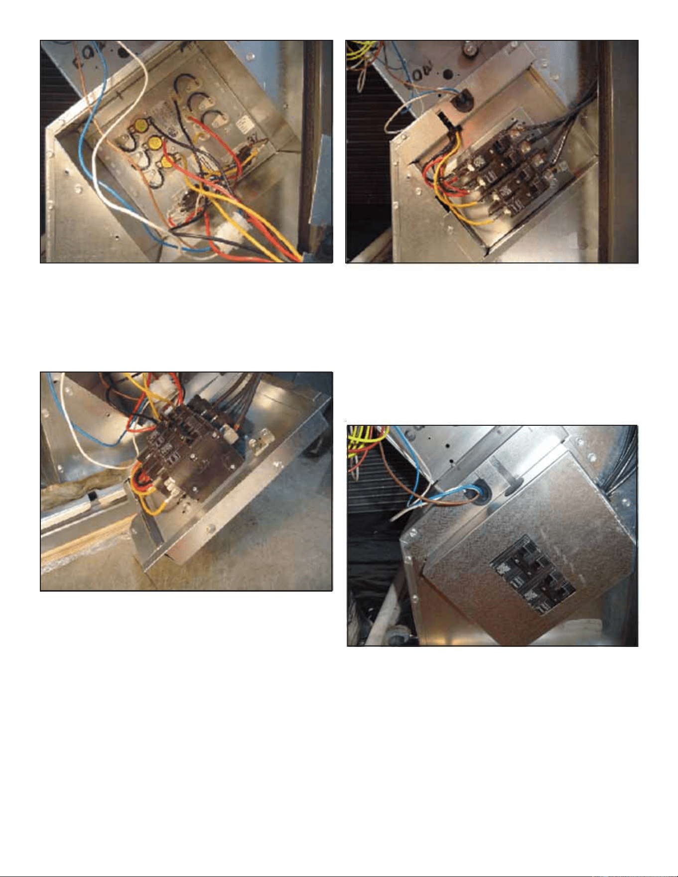
8. For single phase HKR kits only, mount the breaker (or termi-
nal block) to the rear mounting plate using the 4 blunt tip screws
included in the unit literature bag. The screw heads should all
be located on the outside of the mounting plate as shown in
Figure 4.
Figure 4
9. Locate the 9-pin harness in the unit and remove the male plug.
10. Connect the 9-pin plug from the unit to the 9-pin plug in the
heater kit.
11. Feed 9-pin harness wires through the rubber grommet, and
feed HKR wires through the plastic bushing in the rear mount-
ing plate. See Figure 5.
Figure 5
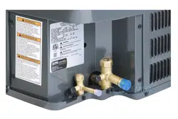
12. Install rear mounting plate with the 2 screws removed in step
6.
13. Connect the line voltage leads to the breaker(s), terminal block,
or contactor as applicable.
14. If heat kit includes breakers, remove rectangular knockout(s)
from outside cover as required for access.
15. Install the cover with the 2 screws removed in step 4, routing
the line voltage wires through the rubber grommet as shown
in Figure 6.
Figure 6
16. Install control box door and blower door.
17. Reconnect power and test.
Visit our websites at www.goodmanmfg.com or amana-hac.com for information on:
• Products • Parts
• Warranties • Contractor Programs and Training
• Customer Services • Financing Options
© 2006-2008 Goodman Manufacturing Company, L.P.
SHORT
SCREWS
Î
Î
LINE
VOLTAGE
Î
Î
HKR
WIRES
THROUGH
PLASTIC
BUSHING
Î
HARNESS WIRES
THROUGH
RUBBER GROMMET
AIR FLOW
DIRECTION
LABEL
Î