Do not mount the speed sensor directly in the path
of the prop. The speed sensor can cause cavitation
that may degrade the boat’s performance and
damage the prop.
Water Speed Sensor
Installation Instructions
Contents
Mounting Hardware
(×2)
1
/
4
in. Cable clamps (×1) Plastic spacer
(×4) 4 × 12 mm Screws (×1) 10-32 × 1
3
/
4
in. Screw
(×1)
1
/
4
in. Rubber washer (×1) 10-32 Lock nut
(×2) 5 mm Flat washers (×1) Cable entry cover
(×2) M5 × 30 mm Screws
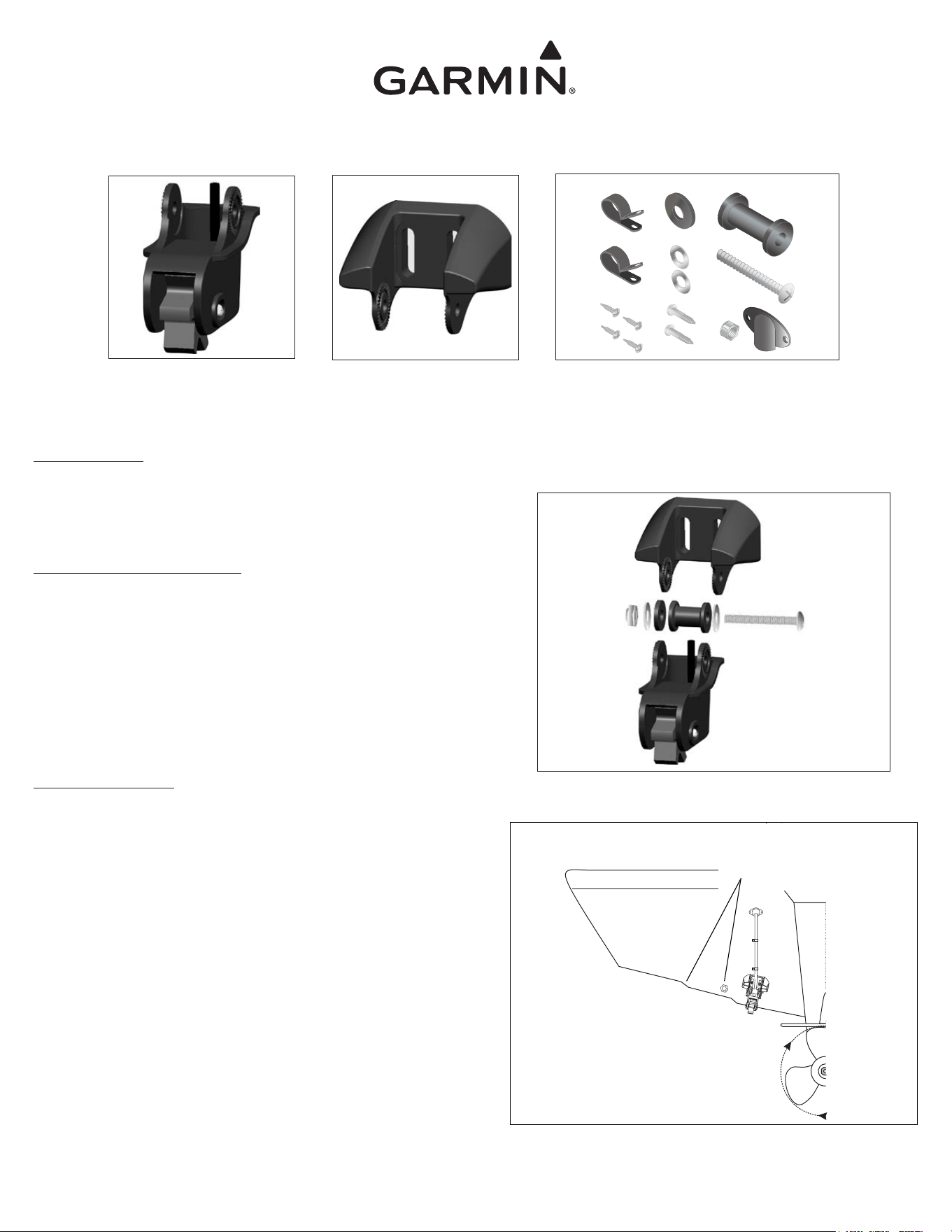
Assembling the Speed Sensor
1. Insert the rubber washer and the plastic spacer into the speed sensor at the
same time. Do not lubricate the rubber washer.
2. Slide the speed sensor into the mounting bracket.
3. Place a 5 mm flat washer on the 10-32 × 1
3
/
4
in. screw and insert the
screw through the mounting bracket, the spacer, and the rubber washer.
4. Place the remaining 5 mm flat washer on the exposed end and install the
10-32 lock nut finger tight (see Figure 1). The speed sensor will be tight-
ened further after installation on the boat.
Selecting a Location
For the speed sensor to operate properly, it should be located in non-tur-
bulent water. The speed sensor should be mounted as close to the center of
the boat as possible. The speed sensor should be positioned so that it is not
in the path of the prop, nor in the path of items on the hull that may cause
the water to become turbulent (Figure 2).
Do not place the speed sensor near strakes, struts, fittings, water
intake or discharge ports, or anything that causes the water to
become turbulent.
Figure 1
Speed Sensor
Transom Mounting Bracket
Mounts to the transom and holds
the speed sensor.
Figure 2
Tools Needed
Drill and drill bits Scissors and masking tape
Number 2 Phillips screw driver Marine sealant
3
/
8
in. Wrench or socket
Part Number 190-00226-00 Rev. B Printed in TaiwanJuly 2009
Do
not place the speed sensor near strakes, struts,
fittings, water intake or discharge ports, or anything
that causes the water to become turbulent.
Mounting the Speed Sensor
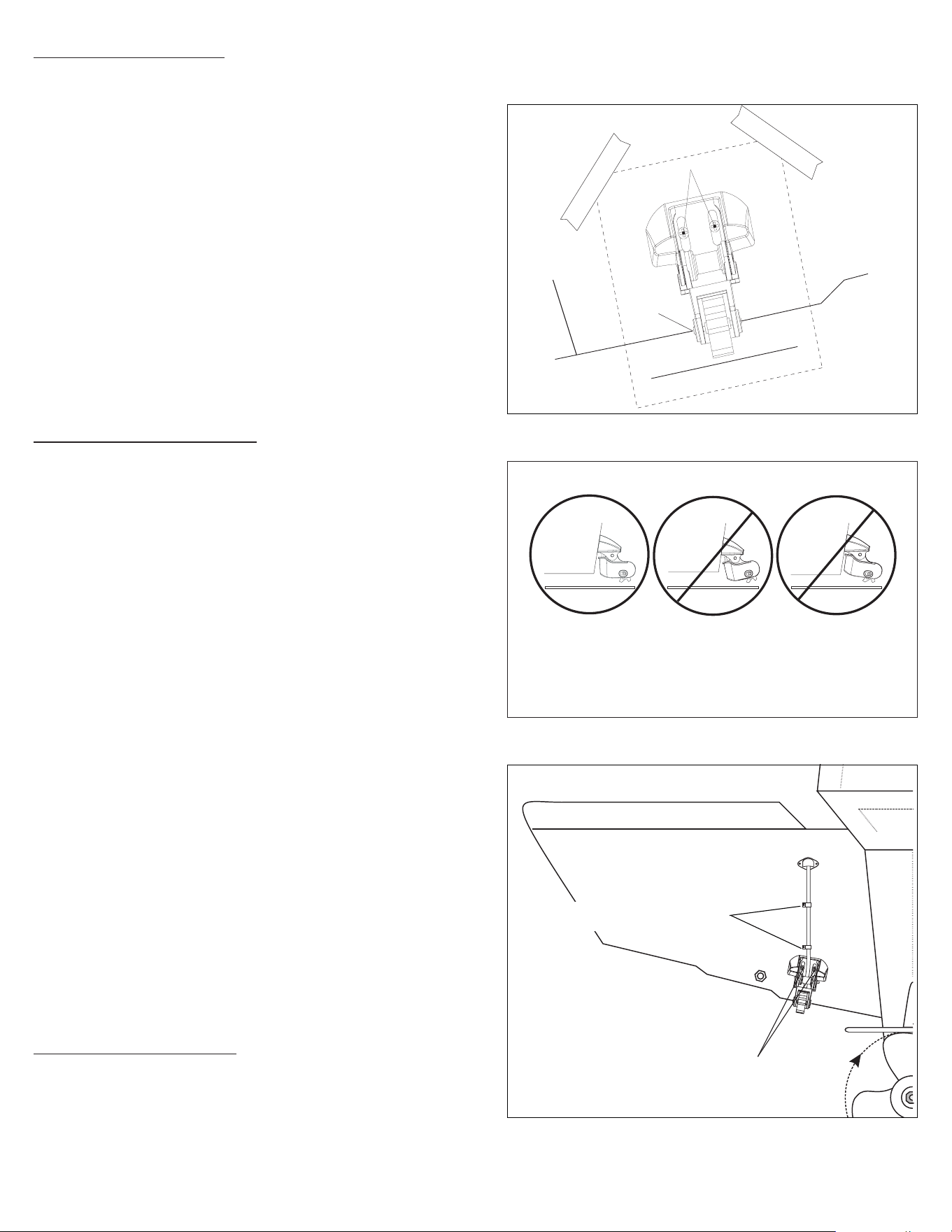
1. Cut out the speed sensor mounting template provided with this document.
2. Position the template at the selected location, ensuring that the mark on
the template is aligned with the bottom of the transom. Tape the template
in place (see Figure 3).
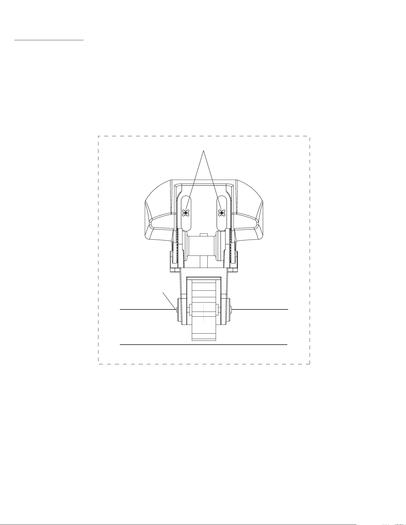
3. Drill
5
/
32
in. (4 mm) pilot holes approximately 1 in. (25 mm) deep at the
locations indicated on the template. To avoid drilling the holes too deep,
wrap a piece of tape around the bit 1 in. (25 mm) from the point of the bit.
Remove the template from the transom.
4. Apply marine sealant to the M5 × 30 mm screws.
5. Attach the speed sensor assembly to the transom using the M5 × 30 mm
screws. Adjust the speed sensor to extend beyond the bottom of the transom
approximately
1
/
8
in. (3 mm) on fiberglass hulls or
3
/
8
in. (10 mm) on alumi-
num hulls. Examine the alignment of the speed sensor; it should be aligned
parallel to the water (see Figure 4).
6. Tighten the 10-32 locking nut until it touches the mounting bracket, and
then tighten it an additional
1
/
4
turn (do not overtighten).
Routing the Speed Sensor Cable
It may be possible to route the speed sensor cable through an existing
drain hole, or it may be necessary to drill a hole in the transom to route the
cable through. Before drilling through the transom, ensure that any wires,
cables, or lines are removed from the area inside the boat.
1. Drill a
3
/
4
in. (19 mm) hole through the transom far above the water line.
2. Route the speed sensor cable through the transom.
3. Place the first cable clamp on the speed sensor cable approximately one
third of the distance between the speed sensor and the hole. Mark the
location. Drill a
1
/
8
in. (3 mm) pilot hole approximately
3
/
8
in. (10 mm) deep.
4. Coat a 4 × 12 mm screw with marine sealant and use it to secure the cable
clamp.
5. Place the second cable clamp on the speed sensor cable approximately two
thirds of the distance between the speed sensor and the hole. Mark the
location. Drill a
1
/
8
in. (3 mm) pilot hole approximately
3
/
8
in. (10 mm) deep.
6. Repeat step 4 for the second cable clamp.
7. Coat the inside of the
3
/
4
in. (19 mm) hole with marine sealant. Place the
cable entry cover over the speed sensor cable and the
3
/
4
in. hole, and then
mark the screw locations. Drill
1
/
8
in. (3mm) pilot holes approximately
3
/
8
in.
(10 mm) deep. Coat the 4 × 12 mm screws with marine sealant, and then
secure the cable entry cover to the transom.
When routing the speed sensor cable to the sonar or to the GST™ 10
adapter, avoid routing the cable close to electrical wires or other sources of
electrical interference. Do not cut the cable jacket while routing the cable.
Do not cut the speed sensor cable. If the cable is too long, coil the extra
cable and secure it using a cable tie. If the cable is too short, contact your
Garmin dealer for an extension cable.
Calibrating the Speed Sensor
When you place your boat in the water, check for leaks around the screw
holes that are below the water line. Do not leave your boat in the water for
an extended period of time without checking for leaks.
Consult your sonar or chartplotter owner’s manual or the GST 10 Instal-
lation and Configuration Instructions for directions on calibrating the speed
sensor.
Figure 3
K
e
e
p
p
a
r
a
l
l
e
l
w
i
t
h
b
o
t
t
o
m
of
b
oa
t
D
r
i
l
l
P
i
l
o
t
H
o
l
e
s
h
e
r
e
Align with transom bottom
Drill a
3
/
4
in. (19 mm) hole far above the water
line. Coat the inside of the hole with marine
sealant.
Position the cable clamps approximately one third
and two thirds of the distance from the hole to the
speed sensor.
Drill
1
/
8
in. (3 mm) pilot holes
3
/
8
in. (10 mm) deep, for all of
the 4 × 12 mm mounting screws. Coat the screws with marine
sealant before installing them.
Figure 4
Figure 5
OK
Adjust the speed sensor so that is is parallel with the bottom of the boat. If the speed
sensor is not adjusted properly, it will experience degraded performance, and it may
not operate at high speeds.
Bottom of transom
Keep parallel with bottom of boat
Drill Pilot Holes here
Align with transom bottom
TEMPLATE
Testing the Installation
1. Start slowly and gradually increase the boat speed. Verify that the speed reading does not fluctuate.
2. If the speed reading fluctuates, adjust the speed sensor so that it extends another
1
/
8
in. below the transom of the boat. It may take several adjustments to
eliminate the degradation.
3. Ensure that the sensor is parallel with the bottom of the boat (see
Figure 4). High-speed operation will be severly degraded if the sensor is not properly aligned.
4. If the reading does not improve, it may be necessary to move the speed sensor to a different location.

© 2000-2009 Garmin Ltd. or its subsidiaries
Garmin International, Inc.
1200 East 151
st
Street, Olathe, Kansas 66062, USA
Garmin (Europe) Ltd.
Liberty House, Hounsdown Business Park, Southampton, Hampshire, SO40 9LR UK
Garmin Corporation
No. 68, Jangshu 2
nd
Road, Shijr, Taipei County, Taiwan
www.garmin.com
July 2009 Part Number 190-00226-00 Rev. B Printed in Taiwan
