TRIPLETT
84-885
3-10
Model
Digital Multimeter
Instruction Manual
9007

1. Introduction
2. Safety Rules and Warnings
3. International Symbols
4. Product Features
5. Specications
Table of Contents
Page 1
6. Front Panel
7. Measurement Procedures
8. Test Lead Holders and Stand
9. Maintenance
10. Accessories
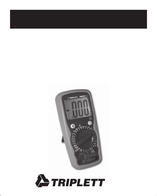
1: INTRODUCTION
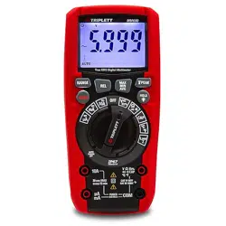
The Triplett 9007 is a ruggedized 3 ½ digit (2000 count) high perfor-
mance precision digital multimeter with a large backlit high contrast
LCD display. Its offering of measurement features includes AC and DC
Voltage and Current, Resistance, Continuity, Diode Test, and Capaci-
tance. The overmolded housing provides impact and drop resistance
in a sleek ergonomic package, and the convenient Auto Power Off
feature maximizes battery life. Its industry leading CAT IV design
provides superior resistance to damage from transient overvoltages
such as those experienced in demanding industrial settings. The 9007
is well suited for use in all test environments, from occasional use in
residential applications, to everyday use by installers, home theater
technicians, security technicians, electricians, HVAC technicians, and
other professionals in the electrical and electronics industry.

Page 2
2: SAFETY RULES & WARNINGS
2.1 Read all instructions in this manual before using this meter.
Failure to do so may result in damage to the meter or injury
to the user.
2.2 Prior to using the meter in any situation which could result
in injury to the user, in order to verify that the meter is
functional and producing a valid reading, test the meter on
a circuit(s) known to have potentials equivalent to the
potential that is to be measured. For example, before using
the meter to determine if an AC power line is energized with
120VAC, test the meter on a line known to be energized with
120VAC. Failure to do so may result in damage to the meter
or injury to the user.
2.3 Do not use this meter with its case open, or with parts
removed. Doing so may damage the meter and/or injure
the user.
2.4 When using this meter in schools and workshops,
responsable teachers or skilled personnel must control the
usage of this meter. Failure to observe this precaution may
result in damage to the meter or injury to the user.

Page 3
2.5 Follow the recommendations of any Trade Organizations or
Regulatory Agencies whose scope encompasses the use of
this meter. Failure to do so may result in damage to the
meter or injury to the user.
2.6 Do not open this meter for maintenance without rst
disconnecting the test leads from all external circuitry.
Failure to observe this precaution may result in damage
to the meter or injury to the user.
2.7 Repairs and maintenance must only be carried out by
qualied service personnel or qualied electricians /
technicians who know the dangers of, and the safety rules
applicable to this type of equipment. Failure to observe this
precaution may result in damage to the meter or injury to
the user.
2.8 Always set the meter to the appropriate range or mode
before connecting it to the circuitry to be tested. Failure to
observe this precaution may result in damage to the meter
or injury to the user.
2.9 Check the condition of the test leads before making a
measurement. Do not use the test leads if there is damaged
insulation or exposed metal. Failure to observe this

Page 4
precaution may result in damage to the meter or injury to
the user.
2.10 Make sure test leads are properly inserted and seated in the
meter’s input jacks. A loose test lead may cause the user
to believe that no hazard exists, when in fact, dangerous
voltages or currents may be present. Failure to observe
this precaution may result in damage to the meter or injury
to the user.
2.11 Do not touch the tips of the test leads when making a
measurement. Do not touch live circuitry when making a
measurement. Failure to observe this precaution may result
in damage to the meter or injury to the user.
2.12 Before using the meter, examine both the meter and the test
leads for damage. Do not use the meter if damage (damaged
insulation, exposed metal, cracked case, burnt smell, etc.) is
evident. Failure to observe this precaution may result in
damage to the meter or injury to the user.
2.13 Insert the test leads in the jacks specied in the instructions
for performing particular tests. Inserting the test leads in
incorrect jacks can damage the meter and/or injure the user.
Page 5
2.14 Do not exceed the maximum voltage or current limitations
of the meter (see product specications). Doing so may
damage the meter and/or injure the user.
2.15 Do not apply voltage or current to the input of the meter
when it is set to any of the Ohms Ω ranges. Doing so may
damage the meter and/or injure the user.
2.16 Do not apply voltage or current to the input of the meter
when it is set to the Diode Test or Continuity Beeper
modes. Doing so may damage the meter and/or injure
the user.
2.17 Do not attempt to measure a voltage source with the test
leads plugged into the meter’s uAmA or 20A jacks. Doing
so may damage the meter and/or injure the user.
2.18 Do not rotate the Function switch with the test leads
connected to the circuitry to be tested. Doing so may
damage the meter or the circuitry, and/or injure the user.
2.19 Replace fuses only with exact or equivalent fuses.
Do not “bridge” fuses out of circuit. Failure to observe
this precaution may result in damage to the meter or
injury to the user.

Page 6
2.20 Do not apply voltages to the input of the meter which are
elevated above the earth ground potential by more than
600V AC/DC. Doing so may damage the meter and/or
injure the user.
2.21 Do not continue to use meter when the “low battery” symbol
is displayed. The displayed reading may be in error and
lead the user to believe that no hazard exists, when in fact,
dangerous voltages or currents may be present. Failure to
observe this precaution may result in damage to the meter
or injury to the user.
2.22 Use caution when working with voltages above 25 volts AC
or 35 volts DC. Such voltages may cause a life threatening
electrical shock.
2.23 This meter is not for use by children. Failure to observe
this precaution may result in damage to the meter or injury
to the user.
2.24 Do not use this meter to make measurements in adverse
environments such as rain, snow, fog, or locations with
steam, explosive gases or dusts. Doing so may damage
the meter and/or injure the user.

Page 7
2.25 Do not use meter in condensing atmospheres. That is, do
not use meter in conditions where ambient temperature and
humidity could cause condensation of water inside of meter.
Doing so may cause injury to the user.
2.26 Do not use the meter if either the meter or the test leads are
wet, either from exposure to the weather, or after cleaning
the case of the meter. Doing so may cause injury to the user.
2.27 Do not attempt immediate use of the meter when bringing
it from a cold environment to a warm environment.
Condensation of water, inside and outside of the meter, may
produce dangerous measuring conditions. Allow the meter
to warm to room temperature before using. Failure to
observe this precaution may result in damage to the meter
or injury to the user.
2.28 Do not modify the meter. Changing the design may make
the meter unsafe and may result in injury to the user.
2.29 Use caution when attempting to evaluate if a dangerous
voltage is present. The meter will not read AC voltage if it
is set to DC, nor will it read DC if it is set to AC.
For example, if the meter is set to 200VDC, it will not
measure a dangerous AC voltage, even if the probes are

Page 8
inserted into a household AC wall outlet.
2.30 Do not touch the metallic portion of one test lead if the other
test lead is connected to a live circuit. The current from the
live circuit may pass through the meter and appear on the
unconnected test lead. Failure to observe this warning may
result in user injury.
2.31 Do not attempt to use meter when no display is present on
LCD. Doing so may damage the meter and/or injure the user.
2.32 Use caution when measuring circuits containing capacitors.
Capacitors can store dangerous or lethal levels of electricity,
even when the circuitry which they are in has been
disconnected from its power source. Some capacitors
could source enough energy to damage the meter and/or
injure the user.
2.33 Do not use the meter if there is evidence of chemical leakage
from the battery. Leakage could damage meter and lead to
injury of user.

Page 9
2.34 Do not use this meter to measure current in circuits whose
open circuit voltage exceeds 250V AC/DC. The meter’s fuses
are rated at 250V max. Failure to observe this precaution
may result in damage to the meter or injury to the user.
2.35 When you use the meter to check a high-voltage circuit, do
not try to connect both test leads at once. Instead, clip one
probe to the neutral or ground lead of the circuit (usually
a bare, green, or white wire in AC wiring circuits) using the
insulated slip-on Alligator Clips. Then probe for voltages
with the other test lead. This helps prevent you from
accidentally touching a hot wire, since you need to
concentrate on only one test lead. Failure to observe
this precaution may result in damage to the meter or
injury to the user.
2.36 If there is any doubt about the condition of the meter
(i.e. safe vs unsafe), remove the meter from service and
secure it in a location that will prevent its unintentional use.
Failure to observe this precaution may result in damage to
the meter or injury to the user.

Page 10
2.37 Do not use the meter if it does not appear to work correctly
on all ranges and in all modes. Failure to observe this
precaution may result in damage to the meter or injury
to the user.
2.38 Do not use the meter if it has undergone long-term storage
under unfavorable conditions. Failure to observe this
precaution may result in damage to the meter or injury
to the user.
2.39 Do not use the meter if it may have been damaged in
transport. Failure to observe this precaution may result
in damage to the meter or injury to the user.
2.40 Always connect one of the meter’s alligator clips to the low
side of a power circuit rst. Never clamp onto a hot wire
rst, (usually red, black, or blue in AC wiring circuits.)
If you clamp onto a hot wire rst, and touch the other
probe, you could receive a shock. Failure to observe this
precaution may result in damage to the meter or injury
to the user.

Page 11
2.41 To avoid damage to the meter and possible user injury,
disconnect test leads from test points before changing the
function/range. Failure to observe this precaution may result
in damage to the meter or injury to the user.
2.42 Avoid usage near strong magnetic elds (magnets,
loudspeakers, transformers, motors, coils, relays,
contactors, electromagnets, etc.). The meter may display
readings that are in error, causing the user to misinterpret
the hazards present. For example, the meter may indicate a
low voltage when high voltages are actually present. Failure
to observe this precaution may result in damage to the meter
or injury to the user.
2.43 Avoid usage near strong electrostatic elds (high voltage
power lines, televisions, computer monitors, etc.).
The meter may display readings that are in error, causing
the user to misinterpret the hazards present. For example,
the meter may indicate a low voltage when high voltages
are actually present. Failure to observe this precaution may
result in damage to the meter or injury to the user.

Page 12
2.44 Avoid usage near strong RF elds (radio or television
transmitters, walkie talkies, cellular phones, etc.).
The meter may display readings that are in error, causing
the user to misinterpret the hazards present. For example,
the meter may indicate a low voltage when high voltages are
actually present. Failure to observe this precaution may
result in damage to the meter or injury to the user.
2.45 Remove the battery when the meter may be left unused for
longer than 1 month. Chemical leakage from the battery
could damage the meter, leading to user injury.
2.46 Do not attempt to test charged capacitors. Only discharged
capacitors may be tested. If you wish to test a capacitor,
discharge it using an approved method before connecting it
to the meter.
Caution: Some capacitors can store dangerous
lethal charges. Discharging these capacitors can be
dangerous unless an approved method is used. Failure
to observe this precaution may result in damage to the
meter or injury to the user.
Page 13
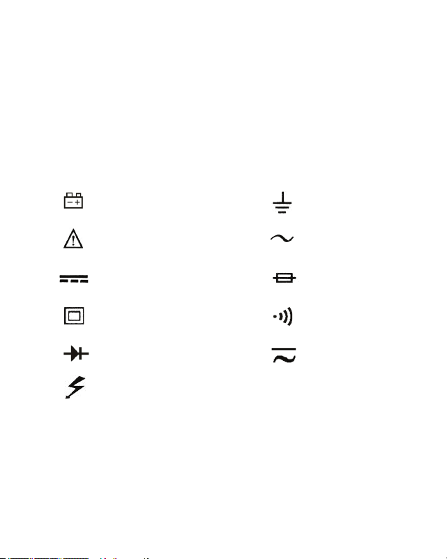
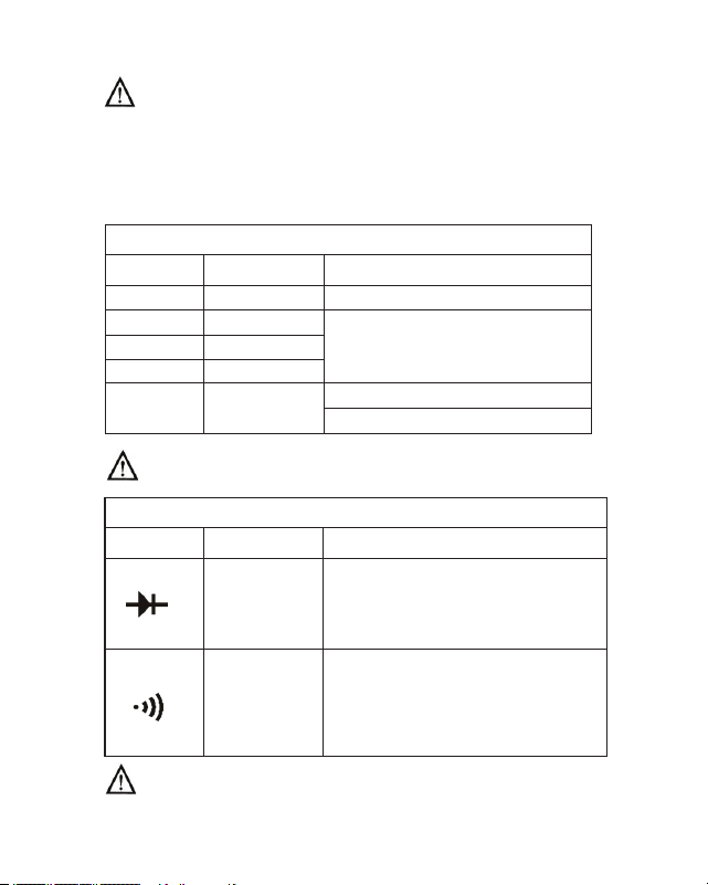
3: INTERNATIONAL SYMBOLS
The following International Symbols may be used in this manual
and on the case of the meter to identify, caution, or warn the user of
important product limitations or important operational procedures
that must be followed to ensure safe usage of the product.
Low Battery
See Instruction Manual
DC
Double Insulated
Diode
Dangerous Voltages
Ground
AC
Fuse
Beeper
AC or DC

Page 14
4: PRODUCT FEATURES
4.1 31 Measurement Ranges
4.2 Huge 1.4” tall High Contrast LCD display
4.3 White LCD Backlight allows viewing in poorly lit areas
4.4 3 1/2 digit resolution (2000 counts)
4.5 Protective shock absorbing overmolded shell with built in
stand and test lead holders
4.6 Diode Test
4.7 Continuity Beeper
4.8 Capacitance Test
4.9 Auto Power Off
4.10 Fused mA and Amp ranges
4.11 Overload protection
4.12 Double Insulated
4.13 CE Mark (EMC / LVD)
4.14 CAT I, II, III, and IV compliance (see Specications for details)

Page 15
5: SPECIFICATIONS
5.1 Display: ..............................1.4” (35mm) high LCD
5.2 Display Resolution: ............2000 counts, 0000 to 1999
5.3 Overrange Indication: .........First digit displays “1”, remaining
digits are blank
5.4 Measurement Rate: .............2 times per second
5.5 Low Battery Annunciator: ..
5.6 Operating Conditions:
Temperature: ......……........0 to 50 degrees C
(32 to 122 degrees F)
Relative Humidity:…...........less than 70%
5.7 Storage Conditions:
Temperature: .......…...........-20 to 60 degrees C
(-4 to 140 degrees F)
Relative Humidity….............less than 80%
5.8 Case Dimensions: ...............17.8 x 8.2 x 5.6 cm, (L x W x H)
7 x 3.2 x 2.2 inches (L x W x H)
5.9 Weight (w battery) ………..Approx 400 grams, 0.88 lbs.
5.10 Battery: ...................…........1 standard 9 volt alkaline battery
NEDA 1604, Triplett Part No. 37-48
5.11 Battery Life: ........…............Typically 200 hours
5.12 Fuses: .................…............0.2A / 250 volt FAST, 5 x 20mm
fuse, for mA ranges. Triplett
Part No. 3207-133

Page 16
20A / 250 volt FAST, 6 x 25mm, for
20A range. Triplett Part No. 3207-134
5.13 Insulation: ..........................Double Insulated (Protection Class II)
5.14 Pollution Degree ………….2
5.15 Approvals: ..........................IEC 1010-1 (EN61010-1)
Overvoltage Category
(Installation Category)
Category I to 1000 volts DC,
700 volts AC
Category II to 1000 volts DC,
700 volts AC
Category III to 1000 volts DC,
700 volts AC
Category IV to 600 volts AC/DC
CE: EMC, LVD
5: SPECIFICATIONS CONT.
Page 17
Note:
a)Thefollowingaccuracyspecicationsarevalidat23degreesC,+/-5
degreesC,RelativeHumiditylessthan75%
b)Thespecicationsareintheform“+/-(x%ofreading+LSD)”
whereLSDis“LeastSignicantDigit”.
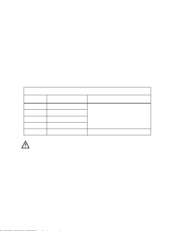
DC Voltage
± (0.8% rdg + 2 digit)
Input Impedance:Allrangesare10MΩ
Overload Protection:200mVRange:250VAC/DCrms.
OtherVDCranges:1000VDC,700VACrms
200.0mV
2.000V
20.00V
200.0V
1000V
Range
Resolution
Accuracy
0.1mV
1mV
10mV
100mV
1V
± (0.5% rdg + 2 digit)
Page 18
AC Voltage
200.0mV
2.000V
20.00V
200.0V
700V
± (1.2% rdg + 5 digits)
± (1.0% rdg + 3 digits)
Input Impedance: Allrangesare10MΩ
Frequency:50Hzto400Hz
Overload Protection: 200mVRange:250VAC/DCrms.
OtherVACranges:1000VDC,700VACrms
Display: AverageValue(RMSofSineWave)
DC Current
2.000mA
20.00mA
200.0mA
20.00A
Overload Protection: 0.2A/250Vfuse
(below200mArange)
20A/250Vfuse(20Arange)
Limitmeasurementtimeon20Arangeto30seconds
forinputsover10A.Allow15minutescooldown
betweenmeasurements.
Range
Resolution
Accuracy
0.1mV
1mV
10mV
100mV
1V
± (1.0% rdg + 5 digits)
1µA
10µA
100µA
10mA
Range
Resolution
Accuracy
±(1.0% rdg + 3 digits)
± (1.5% rdg + 3 digits)
± (2.5% rdg + 10 digits)
Page 19
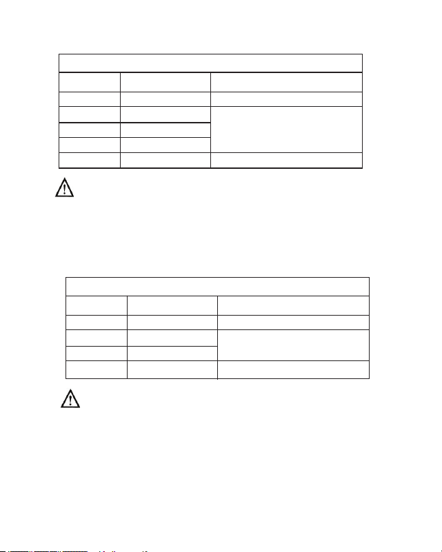
AC Current
Range Resolution Accuracy
2.000mA 1µA ± (1.2% rdg + 3 digits)
200.0mA 100µA ± (2.0% rdg + 3 digits)
20.00A 10mA ± (3% rdg + 10 digits)
Overload Protection:0.2A/250Vfuse
(below200mArange)
20A/250Vfuse(20Arange)
Limitmeasurementtimeon20Arangeto30seconds
forinputsover10A.Allow15minutescooldown
betweenmeasurements.
Display:AverageValue(RMSofSineWave)
Resistance
± (1.0% rdg + 4 digits)
after subtracting any
residual resistance noted
when test leads are shorted.
± (1.0% rdg + 2 digits)
± (1.2% rdg + 2 digits)
± (2.0% rdg + 5 digits)
± [5% (rdg-10) + 10 digits]*
200.0Ω
2.000KΩ
20.00KΩ
200.0KΩ
2.000MΩ
20.00MΩ
200.0MΩ
0.1Ω
1Ω
10Ω
100Ω
1KΩ
10KΩ
100K
Range
Resolution
Accuracy
Page 20
Overload Protection: Allranges250VDCorACRMS.
*On200MOhmrange,itisnormalforthemeterto
display10LSDwiththetestleadsshortedtogether.
Toobtainanaccuratereading,subtract10LSDfrom
thedisplayedvalue.
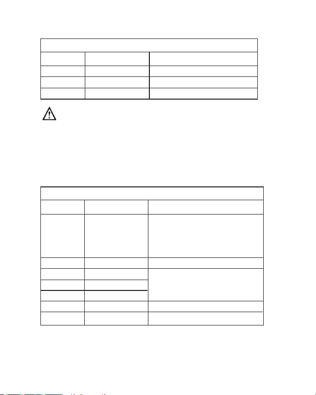
Capacitance
2.000nF
20.00nF
200.0nF
2.000uF
Overload Protection: Allranges250VDCorACRMS.
200.0uF
Diode Test and Continuity Beeper
Range Display Notes
Forward DC current about 1mA
Open circuit voltage about 2.8V
Actual diode
voltage
in volts
Does not
display
resistance
accurately
Beeper sounds if Continuity
Resistance is less than
10 to 30 OhmsΩ
Overload Protection: 250VDCorACRMS.
Range
Resolution
Accuracy
1pF
10pF
0.1nF
1nF
0.1uF
± (4.0% rdg + 70 digits)
± (4.0% rdg + 3 digits)
<20uF, ± (5% rdg + 10 digits)
>20uF, unspecied
Page 21
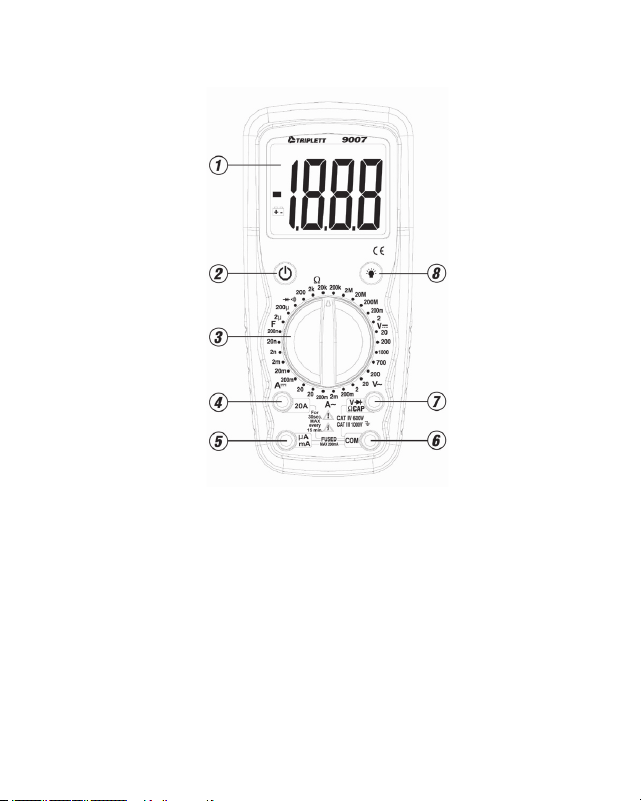
6: FRONT PANEL
1. LCD Display
2. Power Button
3. Function Switch
4. 20A Input Jack
5. uA and mA Input Jack
6. COM Input Jack
7. Volt, Ohm, Capacitance, Diode Test, and Continuity Input Jack
8. Backlight Button
Page 22
7: MEASUREMENT PROCEDURES
WARNING!
Do not use the meter when the low battery symbol is displayed.
This may cause the meter to produce inaccurate readings,
and lead the user to believe that no hazard exists, when,
in fact, dangerous voltages or currents are present.
7.1 LCD Backlight
The 9005-A incorporates a convenient LCD Backlight. The Backlight
provides illumination for the LCD in dimly lit conditions. When the
blue button is pressed, the white LED Backlight will turn on for
about 5 seconds, and then automatically turn off.
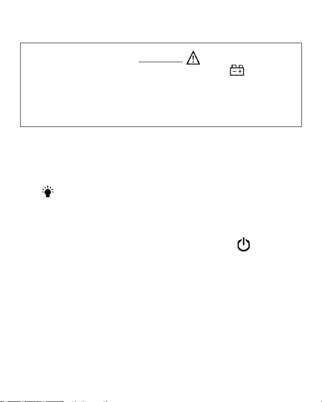
7.2 Power Button and Auto Power Off:
Turn on the 9007 by pressing the yellow power button .
Press it again to turn the meter off.
The 9007 has Auto Power Off. This feature automatically turns the
meter off 10 to 15 minutes after it was turned on....... thereby
extending battery life.
7.3 DC Voltage Measurement:
WARNING!
If the magnitude of the voltage to be measured is unknown, always
start by setting the meter to the highest range, and then to lower
ranges, until a satisfactory reading is obtained.
Do not rotate the RANGE switch with the input applied to the meter.
If the input voltage is higher than 1000VDC (CAT I, CAT II, or CAT
III), or 600V DC (CAT IV), do not attempt to measure!
Use Caution when measuring voltages above 50V DC.
7.3.1 Connect the black test lead to the COM jack and the red test
lead to the VOLT / DIODE / OHM / CAP “V Ω CAP” jack.
7.3.2 Set the RANGE switch to a V position. If the magnitude
of the voltage is unknown, set the RANGE switch to the highest
V position. If the input voltage is higher than the
previously stated limits, do not attempt to measure!
7.3.3 Connect the test probes to circuit being measured.
The LCD will display the DC voltage.
Page 23

Page 24
7.3.4 If the display indicates overrange, i.e. “1- - -”, disconnect the
test probes from the circuit and rotate the RANGE switch to the
next higher position. Reconnect the test probes to the circuit
and observe the reading on the LCD display. If the RANGE
switch is already at the highest position (i.e. 1000 VDC), the
input voltage exceeds the measurement capability of the meter
and should not be measured.
7.3.5 If the displayed value is less than “200” (decimal point not
shown), a more accurate reading may be obtained by setting
the RANGE switch to a lower range. Disconnect the probes
from the circuit and rotate the RANGE switch to the next lower
position. Reconnect the test probes to the circuit and observe
the reading on the LCD display. If the RANGE switch is already
on the lowest position (i.e. 200m VDC), no greater
measurement resolution can be obtained.
Page 25
7.4 AC Voltage Measurement:
WARNING!
If the magnitude of the voltage to be measured is unknown, always
start by setting the meter to the highest range, and then to lower
ranges, until a satisfactory reading is obtained.
Do not rotate the RANGE switch with the input applied to the meter.
If the input voltage is higher than 700VAC (CAT I, CAT II, CAT III), or
600VAC (CAT IV), do not attempt to measure!
Use Caution when measuring voltages above 30V AC.
7.4.1 Connect the black test lead to the COM jack and the red test
lead to the VOLT / DIODE / OHM / CAP “V Ω CAP” jack.
7.4.2 Set the RANGE switch to a V~ position. If the magnitude
of voltage is unknown, set the RANGE switch to the highest
V~ position. If the input voltage is higher than the previously
stated limits, do not attempt to measure!
7.4.3 Connect the test probes to circuit being measured. The LCD will
display the AC voltage.

Page 26
7.4.4 If the display indicates overrange, i.e. “1- - -”, disconnect the
test probes from the circuit and rotate the RANGE switch to the
next higher position. Reconnect the test probes to the circuit
LCD display. If the RANGE switch is already at the highest
position (i.e. 700 VAC), the input voltage exceeds the
measurement capability of the meter and should not be
measured.
7.4.5 If the displayed value is less than “200” (decimal point not
shown), a more accurate reading may be obtained by setting
the RANGE switch to a lower range. Disconnect the probes
from the circuit and rotate the RANGE switch to the next lower
position. Reconnect the test probes to the circuit and observe
the reading on the LCD display. If the RANGE switch is already
on the lowest position (i.e. 200m AC), no greater measurement
resolution can be obtained.
Page 27
7.5 DC Current Measurement:
WARNING!
If the magnitude of the current to be measured is unknown,
always start by setting the meter to the highest range, and then
to lower ranges, until a satisfactory reading is obtained.
Do not rotate the RANGE switch with the input applied to the meter.
If the input current is higher than 20A, do not attempt to measure!
Use caution when measuring current in a circuit with voltages
above 50 VDC. Do not use meter to measure current in
circuits whose voltage exceeds 250V AC/DC.
7.5.1 Connect the black test lead to the COM jack. Connect the red test
lead to the 20A jack unless it is known that the input current is
less than 200mA. If the current is less than 200mA, connect the
red test lead to the uA mA jack.
7.5.2 If the red test lead is inserted into the 20A jack, set the RANGE
switch to the 20 A position. Connect the test leads
IN SERIES with the circuit to be measured. Read the value of the
current on the LCD display.

Page 28
7.5.3 If the red test lead is inserted into the uA mA jack, set the
RANGE switch to the 200m A position. Connect the
test leads IN SERIES with the circuit to be measured.
Read the value of the current on the LCD.
7.5.4 If the display indicates overrange, i.e. “1- - -”, disconnect the
test probes from the circuit and reconnect the red test lead to
the 20A jack. Set the RANGE switch to the 20 A position,
and reconnect the test leads to the circuit. Read the value from
the LCD. If the display indicates overrange, i.e. “1- - -”, the
input current exceeds the measurement capability of the meter,
and should not be measured.
7.5.5 If the displayed value is less than “200” (decimal point not
shown), a more accurate reading may be obtained by setting
the RANGE switch to a lower range. Disconnect the probes
from the circuit and rotate the RANGE switch to the next lower
position. Reconnect the test probes to the circuit and observe
the reading on the LCD display. If the RANGE switch is already
on the lowest position (i.e. 2m), no greater measurement
resolution can be obtained.
Page 29
7.6 AC Current Measurement:
WARNING!
If the magnitude of the current to be measured is unknown, always
start by setting the meter to the highest range, and then to lower
ranges, until a satisfactory reading is obtained.
Do not rotate the RANGE switch with the input applied to the meter.
If the input current is higher than 20A, do not attempt to measure!
Use caution when measuring current in a circuit with voltages
above 30 VAC. Do not use meter to measure current in
circuits whose voltage exceeds 250V AC/DC.
7.6.1 Connect the black test lead to the COM jack. Connect the red
test lead to the 20A jack unless it is known that the input
current is less than 200mA. If the current is less than 200mA,
connect the red test lead to the uA mA jack.
7.6.2 If the red test lead is inserted into the 20A jack, set the RANGE
switch to the 20 A~ position. Connect the test leads IN SERIES
with the circuit to be measured. Read the value of the current on
the LCD display.

Page 30
7.6.3 If the red test lead is inserted into the uA mA jack, set the
RANGE switch to the 200m A~ position. Connect the test
leads IN SERIES with the circuit to be measured.
Read the value of the current on the LCD.
7.6.4 If the display indicates overrange, i.e. “1- - -”, disconnect the
test probes from the circuit and reconnect the red test lead to
the 20A jack. Set the RANGE switch to the 20 A ~ position, and
reconnect the test leads to the circuit. Read the value from the
LCD. If the display indicates overrange, i.e. “1- - -”, the input
current exceeds the measurement capability of the meter, and
should not be measured.
7.6.5 If the displayed value is less than “200” (decimal point not
shown), a more accurate reading may be obtained by setting
the RANGE switch to a lower range. Disconnect the probes
from the circuit and rotate the RANGE switch to the next lower
position. Reconnect the test probes to the circuit and observe
the reading on the LCD display. If the RANGE switch is already
on the lowest position (i.e. 2m), no greater measurement
resolution can be obtained.
Page 31
7.7 Resistance Measurement:
WARNING!
Do not apply voltage or current to the meter when it is set
to any of the “ Ω ” ranges.
7.7.1 Connect the black test lead to the COM jack, and the red test
lead to the VOLT / DIODE / OHM / CAP “V Ω CAP” jack.
7.7.2 Set the RANGE switch to the Ohms “ Ω ” position that is
appropriate for the device or circuit to be measured.
The LCD display will indicate overrange (i.e. “1 - - -”).
7.7.3 Connect the test leads to the device or circuit being measured.
Observe correct polarity if appropriate.
7.7.4 If the display indicates overrange, i.e. “1- - -”, rotate the
RANGE switch to the next higher position and observe the
reading on the LCD display. If the RANGE switch is already
at the highest position (i.e. 200M Ohms), the resistance
exceeds the value measurable by the meter.

Page 32
7.7.5 If the displayed value is less than “200” (decimal point not
shown), a more accurate reading may be obtained by setting
the RANGE switch to a lower range. Rotate the RANGE switch
to the next lower position and observe the reading on the LCD
display. If the RANGE switch is already on the lowest position
(i.e. 200 Ohms), no greater measurement resolution can
be obtained.
Notes:
a)The2M,20M,and200Mrangesrequireseveralsecondstostabilize.
b)The200Mrangereadsabout10LSDhigh.Toobtainanaccurate
reading,shortthetestleadstogetherandobservetheresidule
reading(usually8to12LSD).Forthebestaccuracy,subtract
observedreadingfromsubsequentmeasurements.
c)Toobtainthemostaccuratereadingonthe200
Ωrange,shortthe
testleadstogetherandnotethe“residualresistance”reading.
Itistypicallylessthan0.5
Ω.Subtractthisvaluefromsubsequent
readingsonthe200
Ωrange.
Page 33
7.8 Continuity Beeper:
WARNING!
Do not apply voltage or current to the meter when it is set
to the Diode Test / Continuity Beeper “ ” range.
7.8.1 Connect the black test lead to the COM jack and the red test
lead to the VOLT / DIODE / OHM / CAP “V Ω CAP” jack.
7.8.2 Set the RANGE switch to the Diode Test / Continuity Beeper
“ ” range.
7.8.3 Connect the test probes to the device or circuit to be tested.
7.8.4 If the resistance of the device or circuit is less than 20 to 100
Ohms, the continuity beeper will sound.
Note:ThereadingdisplayedontheLCDisnotanaccurateindicationof
theresistanceofthedeviceorcircuitbeingmeasured.
Page 34
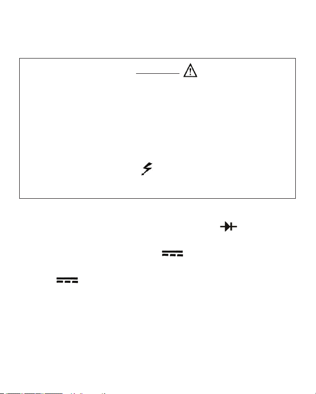
7.9 Diode Test:
WARNING!
Do not apply voltage or current to the meter when it is set
to the Diode Test / Continuity Beeper “ ” range
7.9.1 Connect the black test lead to the COM jack and the red test
lead to the VOLT / DIODE / OHM / CAP “V Ω CAP” jack.
7.9.2 Set the RANGE switch to the Diode Test / Continuity Beeper
“ ” range.
7.9.3 Connect the test probes to the device or circuit to be tested.
To test a simple diode, connect the red test probe to the Anode
of the diode and the black test lead to the Cathode (“banded”
end) of the diode. The LCD will indicate the voltage drop of the
diode. Reverse the connections of the test probes to the diode.
The LCD should indicate overrange (“1 - - -”). If the Continuity
Beeper sounds when the leads are connected in either direction
to a standard silicon diode, the diode is probably shorted.
Note:ThereadingdisplayedontheLCDisanaccurateindicationofthe
voltagedropofthedeviceorcircuitbeingmeasured.
Page 35
7.10 Measuring Capacitance:
WARNING!
Do not apply voltage or current to the meter when it is set
to the Capacitance “F ” ranges. Do not connect a charged capacitor to
the meter. Doing so may damage the meter or injure the user.
7.10.1 Connect the black test lead to the COM jack and the red test
lead to the VOLT / DIODE / OHM / CAP “V Ω CAP” jack.
7.10.2 Set RANGE switch to the F position appropriate for the
measurement to be made.
7.10.3 Connect the test leads to the capacitor to be measured.
Observe proper polarity (if appropriate). Read value from
the LCD display.
7.10.4 If the display indicates overrange, i.e. “1- - -”, rotate the
RANGE switch to the next higher position and observe the
reading on the LCD display. If the RANGE switch is already at
its highest position (i.e. 200u F), and the reading exceeds
20.0, it should be considered inaccurate.

Page 36
7.10.5 If the displayed value is less than “200” (decimal point not
shown), a more accurate reading may be obtained by setting
the RANGE switch to a lower range. Rotate the RANGE switch
to the next lower position and observe the reading on the LCD
display. If the RANGE switch is already on the lowest position
(i.e. 2n F), no greater measurement resolution can be obtained.
Notes:
a)Onthe2nFand20nFranges,themetermayindicateresidual
capacitance.i.eThemeterreadingwillnotgotozero.Thisis
causedbytheinternalcapacitanceofthemetercircuitryorthe
testleads.
b)TheTestLeadsmayintroduceerrorwhenusedonthelow
capacitanceranges(like2nFand20nF).Tominimizetheerror,
notethedifferenceinreadingwiththeleadsinsertedintothe
meterandwiththeleadsremovedfromthemeter,andwhen
usingthetestleads,subtractthenoteddifferencefromthe
displayedreading.

Page 37
8: TEST LEAD HOLDERS STAND, and HANGER
Test Lead Holders are provided on the back of the 9007. The test leads
may be snapped into the back of the meter for storage, or one or both
leads may be snapped into the holders with the tip protruding, forming
a handy ‘meter with probe’ unit.
A built in stand can be ipped out to tilt the meter up to a convenient
angle for use on a table top.
A recess in the back of the meter allows it to be hung from a hook or
nail.

Page 38
9: MAINTENANCE
Your Triplett Model 9007 DMM is a precision measuring instrument
and, when used as described in this manual, should not require
maintenance.
However, periodic calibration of the meter will insure that it is accurate
and performing in accordance with its design specications.
A one year calibration interval is suggested.
To clean the outside of the meter, use a cloth dampened with a mild
detergent solution. Do not use any abrasive cleansers, or chemical
solvents that may damage the case of the meter.

Page 39
9.1 Replacing Battery:
9.1.1 Remove the test leads from the meter.
9.1.2 Remove 1 screw from the top of the battery compartment
cover. Flip the Stand out and remove the screw from the bottom
of the battery compartment cover. The cover is sealed and may
t tightly. A small screwdriver inserted at the top of the cover
may help to remove it.
9.1.3 Remove the 9 volt battery and, observing proper polarity,
replace with a fresh battery (PN 37-48).
9.1.4 Reassemble battery compartment cover. Reinstall screws.
9.1.5 Verify that the meter operates properly before using it to make
measurements.
9.2 Replacing Fuses:
9.2.1 Remove the test leads from the meter.
9.2.2 Remove the 4 screws from the back of the meter case. Flip up
the Stand and remove 2 additional screws. It is not necessary
to remove the battery cover screws.

Page 40
9.2.3 Open the meter case by wiggling the back to separate it from
the front. Set the back of the case to one side.
9.2.4 Locate the defective fuse and replace with the exact or
equivalent type. See meter specications.
9.2.5 Reassemble case of meter. Reinstall screws.
9.2.6 Verify that the meter operates properly before using it to
make measurements.

Page 41
10: ACCESSORIES
10.1 The Triplett Model 9007 package contains the following items:
10.1.1 The Model 9007 DMM
10.1.2 Test leads for the 9007 (Triplett PN 79-808)
10.1.3 Instruction Manual (Triplett PN 84-885)
10.2 Several different carrying cases may be used for the 9007.
Contact a Triplett representative to obtain help with determining
which case will suit your needs.

Triplett Product Return Instructions
In the unlikely event that you must return your Triplett equipment for
repair, the following steps must be taken.
1) Call 1-800-TRIPLETT to obtain a Return Material Authorization
(RMA) number from Customer Service.
2) Enclose a copy of the original sales receipt showing date of
purchase.
3) Clearly print the RMA number on the outside of the shipping
container.
4) Return to: Triplett / Jewell Instruments
850 Perimeter Road
Manchester, NH 03103
ATTN: Repair Dept.
Page 42

Triplett Three Year Limited Warranty
Triplett warrants instruments and test equipment manufactured by it to
be free from defective material or workmanship and agrees to repair or
replace such products which, under normal use and service, disclose
the defect to be the fault of our manufacturing, with no charge within
three years of the date of original purchase for parts and labor.
If we are unable to repair or replace the product, we will make a
refund of the purchase price. Consult the Instruction Manual for
instructions regarding the proper use and servicing of instruments
and test equipment. Our obligation under this warranty is limited
to repairing, replacing, or making refund on any instrument or test
equipment which proves to be defective within three years from the
date of original purchase.
This warranty does not apply to any of our products which have been
repaired or altered by unauthorized persons in any way so as, in our
sole judgment, to injure their stability or reliability, or which have been
subject to misuse, abuse, misapplication, negligence, accident or
which have had the serial numbers altered, defaced, or removed.
Accessories, including batteries and fuses, not of our manufacture
used with this product are not covered by this warranty.
Page 43

Triplett Three Year Limited Warranty
To register a claim under the provisions of this warranty, contact
Triplett’s Customer Service Department for a Return Authorization
Number (RMA) and return instructions. No returned product will be
accepted without an RMA number. Upon our inspection of the product,
we will advise you as to the disposition of your claim.
ALL WARRANTIES IMPLIED BY LAW ARE HEREBY LIMITED TO A
PERIOD OF THREE YEARS FROM DATE OF PURCHASE, AND THE
PROVISIONS OF THE WARRANTY ARE EXPRESSLY IN LIEU OF ANY
OTHER WARRANTIES EXPRESSED OR IMPLIED.
The purchaser agrees to assume all liability for any damages and
bodily injury which may result from the use or misuse of the product
by the purchaser, his employees, or others, and the remedies provided
for in this warranty are expressly in lieu of any other liability Triplett
may have, including incidental or consequential damages.
Some states (USA ONLY) do not allow the exclusion or limitation
of incidental or consequential damages, so the above limitation or
exclusion may not apply to you. No representative of Triplett / Jewell
Instruments or any other person is authorized to extend the liability of
Triplett in connection with the sale of its products beyond the terms
hereof.
Page 44

Triplett Three Year Limited Warranty
Triplett reserves the right to discontinue models at any time, or change
specications, price or design, without notice and without incurring
any obligation.
This warranty gives you specic legal rights, and you may have other
rights which vary from state to state.
Page 45

Page 46