CUB CADET LLC, P.O. BOX 361131 CLEVELAND, OHIO 44136-0019
Printed In USA
Op e r a t O r ’s Ma n u a l
Safe Operation Practices • Set-Up • Operation • Maintenance • Service • Troubleshooting • Warranty
WARNING
READ AND FOLLOW ALL SAFETY RULES AND INSTRUCTIONS IN THIS MANUAL
BEFORE ATTEMPTING TO OPERATE THIS MACHINE.
FAILURE TO COMPLY WITH THESE INSTRUCTIONS MAY RESULT IN PERSONAL INJURY.
Self Propelled Mower — Model Series 990
Form No. 769-04710
(December 15, 2008)

Customer Support
If you have difficulty assembling this product or have any questions regarding the controls, operation, or maintenance of
this machine, you can seek help from the experts. Choose from the options below:
Visit us on the web at www.cubcadet.com◊
Locate your nearest Cub Cadet Dealer at (877) 282-8684◊
Write us at Cub Cadet LLC • P.O. Box 361131 • Cleveland, OH • 44136-0019◊
Thank you for purchasing a Lawn Mower manufactured by Cub
Cadet LLC. It was carefully engineered to provide excellent
performance when properly operated and maintained.
Please read this entire manual prior to operating the equipment.
It instructs you how to safely and easily set up, operate and
maintain your machine. Please be sure that you, and any other
persons who will operate the machine, carefully follow the
recommended safety practices at all times. Failure to do so could
result in personal injury or property damage.
All information in this manual is relative to the most recent
product information available at the time of printing. Review
this manual frequently to familiarize yourself with the machine,
its features and operation. Please be aware that this Operator’s
Manual may cover a range of product specifications for various
models. Characteristics and features discussed and/or illustrated
in this manual may not be applicable to all models. Cub Cadet
LLC reserves the right to change product specifications, designs
and equipment without notice and without incurring obligation.
If you have any problems or questions concerning the machine,
phone your local Cub Cadet dealer or contact us directly. Cub
Cadet’s Customer Support telephone numbers, website address
and mailing address can be found on this page. We want to
ensure your complete satisfaction at all times.
Throughout this manual, all references to right and left side of the
machine are observed from the operating position.
The engine manufacturer is responsible for all engine-related
issues with regards to performance, power-rating, specifications,
warranty and service. Please refer to the engine manufacturer’s
Owner’s/Operator’s Manual, packed separately with your
machine, for more information.
Thank You
Record Product Information
Before setting up and operating your new equipment, please
locate the model plate on the equipment and record the
information in the provided area to the right. You can locate the
model plate by standing at the operator’s position and looking
down at the rear of the deck. This information will be necessary,
should you seek technical support via our web site or with your
local Cub Cadet dealer.
MO d e l nu M b e r
se r i a l nu M b e r
To The Owner
1
2
Safe Operation Practices ........................................ 3
Assembly & Set-Up .................................................. 9
Controls & Features ................................................12
Operation ................................................................13
Maintenance & Adjustment..................................14
Service .....................................................................16
Troubleshooting .....................................................19
Illustrated Parts List .............................................. 22
Warranty ................................................................ 28
Table of Contents

Important Safe Operation Practices
2
3
General Operation
Read this operator’s manual carefully in its entirety before 1.
attempting to assemble this machine. Read, understand,
and follow all instructions on the machine and in the
manuals) before operation. Keep this manual in a safe
place for future and regular reference and for ordering
replacement parts
Be completely familiar with the controls and the proper use 2.
of this machine before operating it.
This machine is a precision piece of power equipment, 3.
not a plaything. Therefore, exercise extreme caution at all
times. This machine has been designed to perform one job:
to mow grass. Do not use it for any other purpose.
Never allow children under 14 years of age to operate this 4.
machine. Children 14 and over should read and understand
the instructions and safe operation practices in this manual
and on the machine and should be trained and supervised
by an adult.
Only responsible individuals who are familiar with these 5.
rules of safe operation should be allowed to use this
machine.
Thoroughly inspect the area where the equipment is to be 6.
used. Remove all stones, sticks, wire, bones, toys and other
foreign objects, which could be tripped over or picked up
and thrown by the blade. Thrown objects can cause serious
personal injury.
Plan your mowing pattern to avoid discharge of material 7.
toward roads, sidewalks, bystanders and the like. Also,
avoid discharging material against a wall or obstruction,
which may cause discharged material to ricochet back
toward the operator.
To help avoid blade contact or a thrown object injury, 8.
stay in operator zone behind handles and keep children,
bystanders, helpers and pets at least 75 feet from mower
while it is in operation. Stop machine if anyone enters area.
Always wear safety glasses or safety goggles during 9.
operation and while performing an adjustment or repair
to protect your eyes. Thrown objects which ricochet can
cause serious injury to the eyes.
Wear sturdy, rough-soled work shoes and close-fitting 10.
slacks and shirts. Shirts and pants that cover the arms
and legs and steel-toed shoes are recommended. Never
operate this machine in bare feet, sandals, slippery or light-
weight (e.g. canvas) shoes.
Do not put hands or feet near rotating parts or under the 11.
cutting deck. Contact with blade can amputate fingers,
hands, toes and feet.
WARNING: This symbol points out important safety instructions which, if not followed,
could endanger the personal safety and/or property of yourself and others. Read and follow
all instructions in this manual before attempting to operate this machine. Failure to comply
with these instructions may result in personal injury.
When you see this symbol. HEED ITS WARNING!
DANGER: This machine was built to be operated according to the safe operation practices in
this manual. As with any type of power equipment, carelessness or error on the part of the
operator can result in serious injury. This machine is capable of amputating fingers, hands,
toes and feet and throwing objects. Failure to observe the following safety instructions could
result in serious injury or death.
CALIFORNIA PROPOSITION 65
WARNING: Engine Exhaust, some of its constituents, and certain vehicle components
contain or emit chemicals known to State of California to cause cancer and birth defects
or other reproductive harm.
WARNING: Battery posts, terminals, and related accessories contain lead and lead
compounds, chemicals known to the State of California to cause cancer and reproductive
harm. Wash hands after handling.

4 se c t i O n 2 — iM p O r t a n t sa f e Op e r a t i O n pr a c t i c e s
A missing or damaged discharge cover can cause blade 12.
contact or thrown object injuries.
Many injuries occur as a result of the mower being pulled 13.
over the foot during a fall caused by slipping or tripping.
Do not hold on to the mower if you are falling; release the
handle immediately.
Never pull the mower back toward you while you are 14.
walking. If you must back the mower away from a wall or
obstruction first look down and behind to avoid tripping
and then follow these steps:
Step back from mower to fully extend your arms.a.
Be sure you are well balanced with sure footing.b.
Pull the mower back slowly, no more than half way c.
toward you.
Repeat these steps as needed.d.
Do not operate the mower while under the influence of 15.
alcohol or drugs.
Do not engage the self-propelled mechanism on machines 16.
so equipped while starting engine.
The blade control handle is a safety device. Never attempt 17.
to bypass its operation. Doing so makes the safety device
inoperative and may result in personal injury through
contact with the rotating blade. The blade control handle
must operate easily in both directions and automatically
return to the disengaged position when released.
Never operate the mower in wet grass. Always be sure of 18.
your footing. A slip and fall can cause serious personal
injury. If you feel you are losing your footing, release the
blade control handle immediately and the blade will stop
rotating within three seconds.
Mow only in daylight or good artificial light. Walk, never 19.
run.
Stop the blade when crossing gravel drives, walks or roads.20.
If the equipment should start to vibrate abnormally, stop 21.
the engine and check immediately for the cause. Vibration
is generally a warning of trouble.
Shut the engine off and wait until the blade comes to 22.
a complete stop before removing the grass catcher or
unclogging the chute. The cutting blade continues to
rotate for a few seconds after the blade control is released.
Never place any part of the body in the blade area until you
are sure the blade has stopped rotating.
Never operate mower without proper trail shield, discharge 23.
cover, grass catcher, blade control handle or other safety
protective devices in place and working. Never operate
mower with damaged safety devices. Failure to do so can
result in personal injury.
Muffler and engine become hot and can cause a burn. Do 24.
not touch.
Never attempt to make a wheel or cutting height 25.
adjustment while the engine is running.
Only use parts and accessories made for this machine by 26.
the manufacturer. Failure to do so can result in personal
injury.
When starting engine, pull cord slowly until resistance 27.
is felt, then pull rapidly. Rapid retraction of starter cord
(kickback) will pull hand and arm toward engine faster than
you can let go. Broken bones, fractures, bruises or sprains
could result.
If situations occur which are not covered in this manual, 28.
use care and good judgement. Contact Customer Support
for assistance or the name of the nearest service dealer.
Slope Operation
Slopes are a major factor related to slip and fall accidents, which
can result in severe injury. Operation on slopes requires extra
caution. If you feel uneasy on a slope, do not mow it. For your
safety, use the slope gauge included as part of this manual to
measure slopes before operating this machine on a sloped or
hilly area. If the slope is greater than 15 degrees, do not mow it.
Do:
Mow across the face of slopes; never up and down. Exercise 1.
extreme caution when changing direction on slopes.
Watch for holes, ruts, rocks, hidden objects, or bumps 2.
which can cause you to slip or trip. Tall grass can hide
obstacles.
Always be sure of your footing. A slip and fall can cause 3.
serious personal injury. If you feel you are losing your
balance, release the blade control handle immediately and
the blade will stop rotating within three (3) seconds.
Do Not:
Do not mow near drop-offs, ditches or embankments, you 1.
could lose your footing or balance.
Do not mow slopes greater than 15 degrees as shown on 2.
the slope gauge.
Do not mow on wet grass. Unstable footing could cause 3.
slipping.
Children
Tragic accidents can occur if the operator is not alert to the
presence of children. Children are often attracted to the mower
and the mowing activity. They do not understand the dangers.
Never assume that children will remain where you last saw them.
Keep children out of the mowing area and under watchful 1.
care of a responsible adult other than the operator.
Be alert and turn mower off if a child enters the area.2.
Before and while moving backwards, look behind and 3.
down for small children.
Use extreme care when approaching blind corners, 4.
doorways, shrubs, trees, or other objects that may obscure
your vision of a child who may run into the mower.
Keep children away from hot or running engines. They can 5.
suffer burns from a hot muffler.
Never allow children under 14 years of age to operate this 6.
machine. Children 14 and over should read and understand
the instructions and safe operation practices in this manual
and on the machine and be trained and supervised by an
adult.

5se c t i O n 2 — iM p O r t a n t sa f e Op e r a t i O n pr a c t i c e s
Service
Safe Handling Of Gasoline:
To avoid personal injury or property damage use extreme 1.
care in handling gasoline. Gasoline is extremely flammable
and the vapors are explosive. Serious personal injury can
occur when gasoline is spilled on yourself or your clothes,
which can ignite. Wash your skin and change clothes
immediately.
Use only an approved gasoline container.2.
Never fill containers inside a vehicle or on a truck or trailer 3.
bed with a plastic liner. Always place containers on the
ground away from your vehicle before filling.
Remove gas-powered equipment from the truck or 4.
trailer and refuel it on the ground. If this is not possible,
then refuel such equipment on a trailer with a portable
container, rather than from a gasoline dispenser nozzle.
Keep the nozzle in contact with the rim of the fuel tank or 5.
container opening at all times until fueling is complete. Do
not use a nozzle lock-open device.
Extinguish all cigarettes, cigars, pipes and other sources 6.
of ignition.
Never fuel machine indoors because flammable vapors will 7.
accumulate in the area.
Never remove gas cap or add fuel while engine is hot or 8.
running. Allow engine to cool at least two minutes before
refueling.
Never over fill fuel tank. Fill tank to no more than 1 inch 9.
below bottom of filler neck to provide for fuel expansion.
Replace gasoline cap and tighten securely.10.
If gasoline is spilled, wipe it off the engine and equipment. 11.
Move machine to another area. Wait 5 minutes before
starting engine.
Never store the machine or fuel container near an open 12.
flame, spark or pilot light as on a water heater, space
heater, furnace, clothes dryer or other gas appliances.
To reduce fire hazard, keep machine free of grass, leaves, 13.
or other debris build-up. Clean up oil or fuel spillage and
remove any fuel soaked debris.
Allow machine to cool at least 5 minutes before storing.14.
General Service:
Never run an engine indoors or in a poorly ventilated area. 1.
Engine exhaust contains carbon monoxide, an odorless
and deadly gas.
Before cleaning, repairing, or inspecting, make certain the 2.
blade and all moving parts have stopped. Disconnect the
spark plug wire and ground against the engine to prevent
unintended starting.
Check the blade and engine mounting bolts at frequent 3.
intervals for proper tightness. Also, visually inspect blade
for damage (e.g., bent, cracked, worn) Replace blade with
the original equipment manufacture’s (O.E.M.) blade only,
listed in this manual. “Use of parts which do not meet the
original equipment specifications may lead to improper
performance and compromise safety!”
Mower blades are sharp and can cut. Wrap the blade or 4.
wear gloves, and use extra caution when servicing them.
Keep all nuts, bolts, and screws tight to be sure the 5.
equipment is in safe working condition.
Never tamper with safety devices. Check their proper 6.
operation regularly.
After striking a foreign object, stop the engine, disconnect 7.
the spark plug wire and ground against the engine.
Thoroughly inspect the mower for any damage. Repair the
damage before starting and operating the mower.
Never attempt to make a wheel or cutting height 8.
adjustment while the engine is running.
Grass catcher components, discharge cover, and trail shield 9.
are subject to wear and damage which could expose
moving parts or allow objects to be thrown. For safety
protection, frequently check components and replace
immediately with original equipment manufacturer’s
(O.E.M.) parts only, listed in this manual. “Use of parts
which do not meet the original equipment specifications
may lead to improper performance and compromise
safety!”
Do not change the engine’s governor setting or over-speed 10.
the engine. The governor controls the maximum safe
operating speed of the engine.
Check fuel line, tank, cap, and fittings frequently for cracks 11.
or leaks. Replace if necessary.
Do not crank engine with spark plug removed.12.
Maintain or replace safety and instruction labels, as 13.
necessary.
Observe proper disposal laws and regulations. Improper 14.
disposal of fluids and materials can harm the environment.
According to the Consumer Products Safety Commission 15.
(CPSC) and the U.S. Environmental Protection Agency (EPA),
this product has an Average Useful Life of seven (7) years,
or 140 hours of operation. At the end of the Average Useful
Life have the machine inspected annually by an authorized
service dealer to ensure that all mechanical and safety
systems are working properly and not worn excessively.
Failure to do so can result in accidents, injuries or death.
Do not modify engine
To avoid serious injury or death, do not modify engine in any
way. Tampering with the governor setting can lead to a runaway
engine and cause it to operate at unsafe speeds. Never tamper
with factory setting of engine governor.

6 se c t i O n 2 — iM p O r t a n t sa f e Op e r a t i O n pr a c t i c e s
Notice Regarding Emissions
Engines which are certified to comply with California and federal
EPA emission regulations for SORE (Small Off Road Equipment)
are certified to operate on regular unleaded gasoline, and
may include the following emission control systems: Engine
Modification (EM), Oxidizing Catalyst (OC), Secondary Air
Injection (SAI) and Three Way Catalyst (TWC) if so equipped.
Spark Arrestor
WARNING: This machine is equipped with an
internal combustion engine and should not be used
on or near any unimproved forest-covered, brush
covered or grass-covered land unless the engine’s
exhaust system is equipped with a spark arrester
meeting applicable local or state laws (if any).
If a spark arrester is used, it should be maintained in effective
working order by the operator. In the State of California the
above is required by law (Section 4442 of the California Public
Resources Code). Other states may have similar laws. Federal laws
apply on federal lands.
A spark arrester for the muffler is available through your
nearest engine authorized service dealer or contact the service
department, P.O. Box 361131 Cleveland, Ohio 44136-0019.
7se c t i O n 2 — iM p O r t a n t sa f e Op e r a t i O n pr a c t i c e s
WARNING: Your Responsibility—Restrict the use of this power machine to persons who read, understand and
follow the warnings and instructions in this manual and on the machine.
SAVE THESE INSTRUCTIONS!
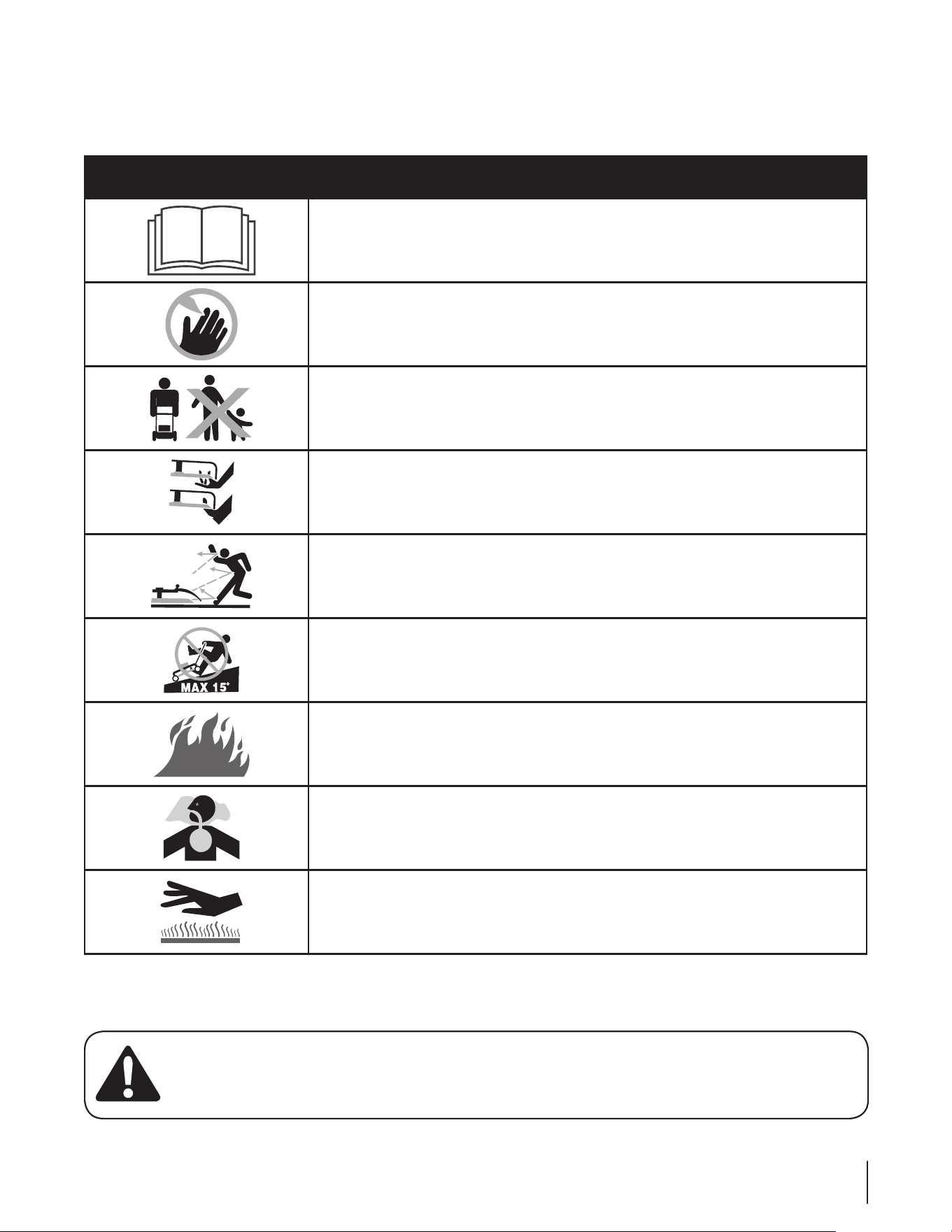
Safety Symbols
This page depicts and describes safety symbols that may appear on this product. Read, understand, and follow all instructions on the
machine before attempting to assemble and operate.
Symbol Description
READ THE OPERATOR’S MANUAL(S)
Read, understand, and follow all instructions in the manual(s) before attempting to
assemble and operate
DANGER — ROTATING BLADES
To reduce the risk of injury, keep hands and feet away. Do not operate unless discharge cover
or grass catcher is in its proper place. If damaged, replace immediately.
DANGER — BYSTANDERS
Do not mow when children or others are around.
DANGER — HAND/ FOOT CUT
Keep hands and feet away from rotating parts.
DANGER — THROWN DEBRIS
Remove objects that can be thrown by the blade in any direction. Wear safety glasses.
DANGER — SLOPES
Use extra caution on slopes. Do not mow slopes greater than 15°.
WARNING—GASOLINE IS FLAMMABLE
Allow the engine to cool at least two minutes before refueling.
WARNING— CARBON MONOXIDE
Never run an engine indoors or in a poorly ventilated area. Engine exhaust contains carbon
monoxide, an odorless and deadly gas.
WARNING— HOT SURFACE
Engine parts, especially the muffler, become extremely hot during operation. Allow engine
and muffler to cool before touching.
8 se c t i O n 2 — iM p O r t a n t sa f e Op e r a t i O n pr a c t i c e s
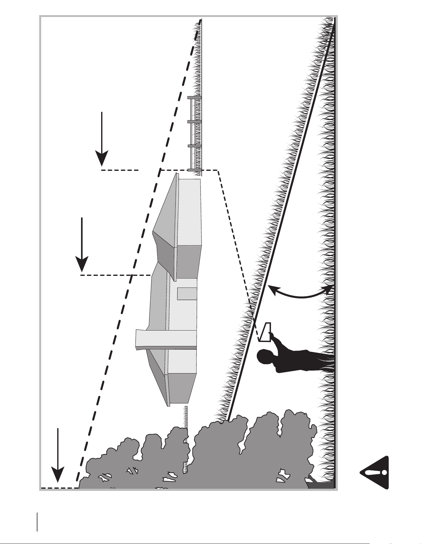
Sight and hold this level with a vertical tree...
or a corner of a building...
or a fence post
Fold along dotted line (represents a 15° slope)
15°
Use this page as a guide to determine slopes where you may not operate safely.
WARNING: Do not operate your lawn mower on such slopes. Do not mow on inclines with a slope in excess of 15 degrees
(a rise of approximately 2-1/2 feet every 10 feet). A riding mower could overturn and cause serious injury. Operate riding
mowers up and down slopes, never across the face of slopes. Operate walk-behind mowers across the face of slopes, never
up and down slopes.
Assembly & Set-Up
3
9
Contents of Carton
One Lawn Mower• One Grass Catcher• One Grass Catcher Adapter•
One Side Discharge Chute• One Engine Operator’s Manual• One Bottle of Oil•
One Lawn Mower Operator’s Manual•
Assembly
NOTE: This unit is shipped without gasoline or oil in the engine.
Fill up gasoline and oil as instructed in the accompanying engine
manual BEFORE operating your mower.
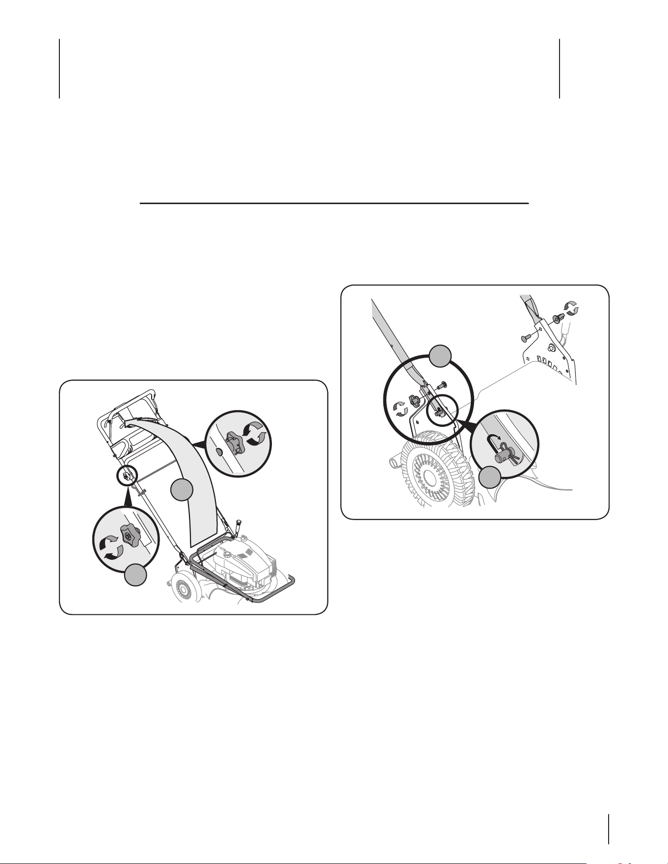
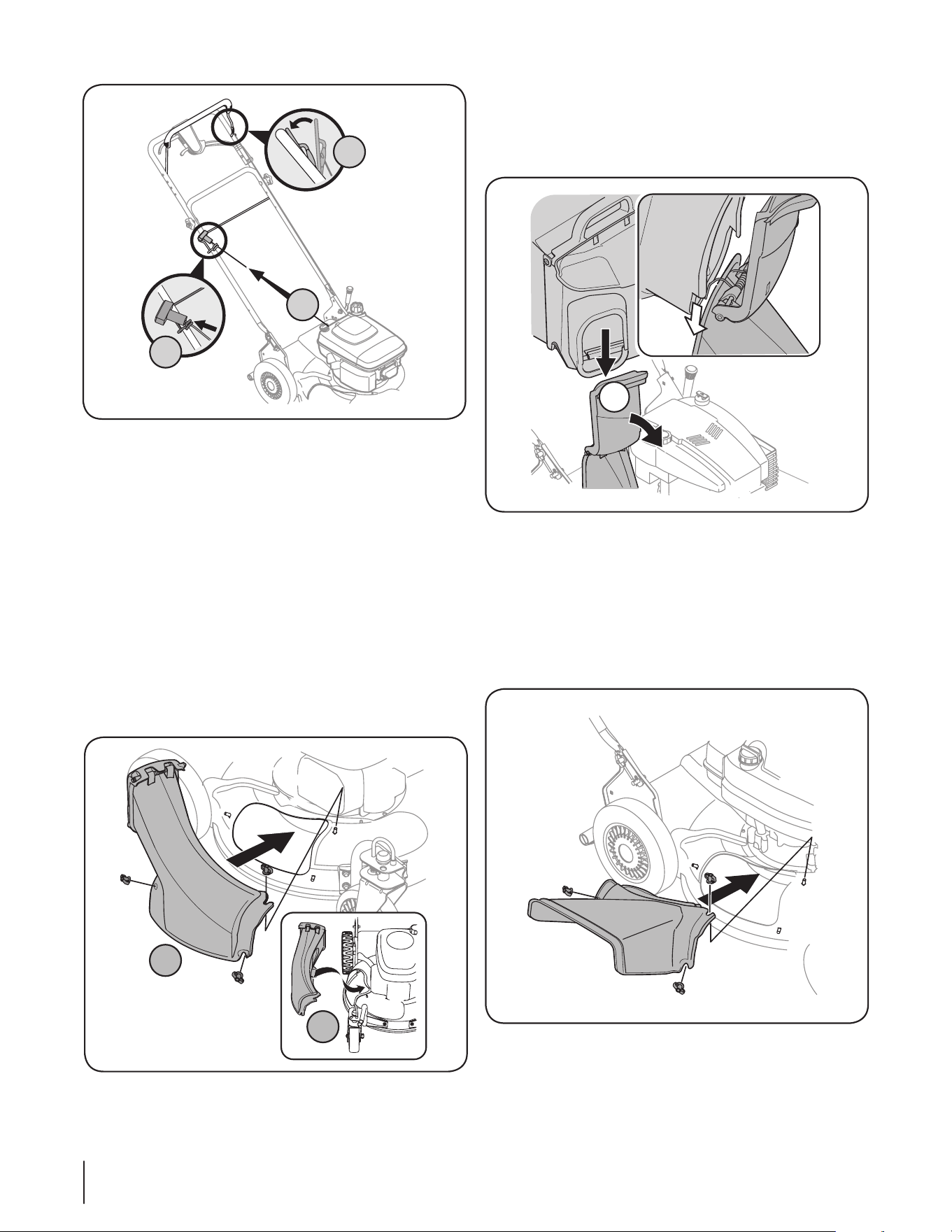
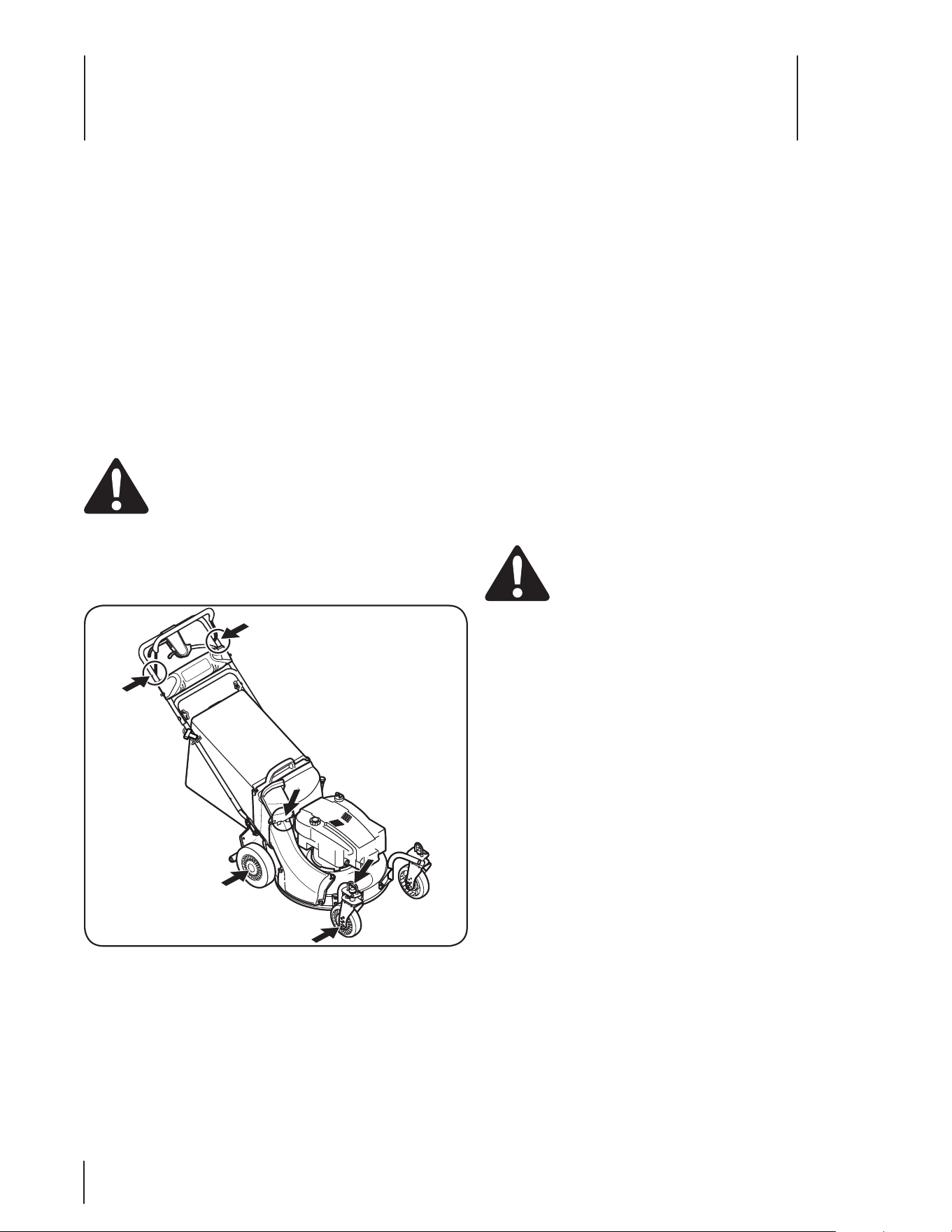
Handle
Remove any packing material which may be between 1.
upper and lower handles.
Pull up and back on upper handle as shown in Fig. a.
3-1. Make certain the lower handle is seated securely
into the handle mounting brackets. Do not crimp
cables while lifting the handle up.
Tighten star knobs to secure upper handle to lower b.
handle. Make sure that each carriage bolt is seated
properly in the handle.
B
A
Figure 3-1
Locate the hairpin clip on the weld pin on each side of lower 2.
handle.
Remove hairpin clip from this hole. Using a pair of a.
pliers, insert hairpin clip into the hole on pin closest
to the bracket. See Fig. 3-2. Repeat on other side.
Insert a carriage bolt from the manual bag into the b.
upper hole on the handle mounting bracket. Secure
with one plastic wing nut, also included in the
manual bag. Repeat on other side with remaining
hardware.
NOTE: Make certain the drive cable is routed around the
outside and above the lower handle so it does not interfere
with attaching the grass bag. The chute door has been
designed to move the starter rope out of the way of the
bag when the chute door is opened.
The rope guide, which is connected to the support rod, is 3.
located on the right side of the lower handle. See Fig. 3-3.
A
B
Figure 3-2
10 se c t i O n 3 — as s e M b l y & se t -up
Replace with grass bag adapter, while making sure the 2.
front lip of adapter goes under the edge of the deck.
Secure with wing nuts previously removed.
Lift chute door on the grass bag adapter and slide grass 3.
bag onto the adapter. See Fig. 3-5.
Side Discharge Chute
Follow steps below to install the side discharge chute:
Remove mulching baffle or grass bag adapter from unit by 1.
disconnecting wing nuts.
Attach side discharge chute to unit and secure with the 2.
three wing nuts. See Fig. 3-6.
Hold blade control against upper handle.a.
Pull starter rope out of the engine. Release blade b.
control.
Slip starter rope into rope guide.c.
Attach cables to the lower handle with the cable ties 4.
already on the lower handle. Insert pegs on cable ties into
the holes on the lower handle. Pull cable ties tight and cut
off the extra.
Grass Catcher
The mower was shipped with the mulching baffle installed on
the unit. For bagging purposes, you will have to attach the grass
bag and its adapter in place of the mulching baffle.
Remove three wing nuts holding the mulching baffle in 1.
place and remove from unit. See Fig. 3-4.
A
C
B
Figure 3-3
Figure 3-4
Figure 3-5
3
2
1
Figure 3-6
11se c t i O n 3 — as s e M b l y & se t -up
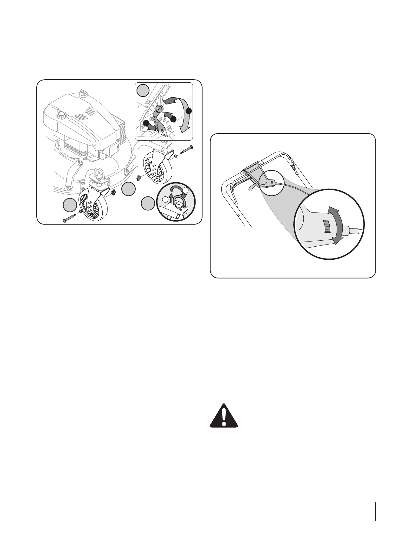
Adjustments
Cutting Height
The cutting height adjustment lever is located above the rear left
wheel. See Fig. 3-7A insert.
Pull lever out and away from mower.1.
Move lever forward or back for desired cutting height.2.
Release lever towards mower deck.3.
The front wheel cutting height is determined by selecting one
of six positions on each caster assembly. To adjust front cutting
height, refer to Fig. 3-7B and proceed as follows:
Remove wing nut from axle bolt. Slide axle bolt and wave 1.
washer from the assembly and select a cutting height.
With wave washer on axle bolt, reinsert hardware in the 2.
square hole desired through wheel assembly and secure
with wing nut previously removed.
IMPORTANT: All wheels must be placed in the same
relative position. For rough or uneven lawns, move the
height adjustment lever to a higher position. This will stop
scalping of grass.
The casters can be locked in a straight ahead position or position
to swivel freely. See Figure 3-7C insert.
Lift lock pins.1.
Place in larger holes to lock wheels. Place pins in smaller 2.
holes to allow casters to rotate freely for turning.
Drive Control
The adjustment wheel is located in the drive control handle
housing and is used to tighten or loosen the drive belt. You will
have to adjust the drive control if any of the following happens:
The mower does not propel itself with the drive control 1.
engaged.
The mower’s drive wheels hesitate with the drive control 2.
engaged.
If either of these conditions occur, rotate the adjustment wheel
clockwise to tighten and counter-clockwise to loosen cable to
adjust the drive control. See Fig. 3-8.
NOTE: For some people the drive control may not be in a
comfortable position. You can adjust the handle by tightening
the adjustment wheel.
Set-Up
Gas and Oil Fill-Up
Refer to the separate engine owner’s manual for additional
engine information.
Add oil provided before starting unit for the first time out 1.
of the box.
Service the engine with gasoline as instructed in the 2.
separate engine owner’s manual.
WARNING: Use extreme care when handling
gasoline. Gasoline is extremely flammable and the
vapors are explosive. Never fuel the machine
indoors or while the engine is hot or running.
Extinguish cigarettes, cigars, pipes and other
sources of ignition.
1
2
3
1
2
C
B
B
A
Figure 3-7
Tighten
Loosen
Figure 3-8
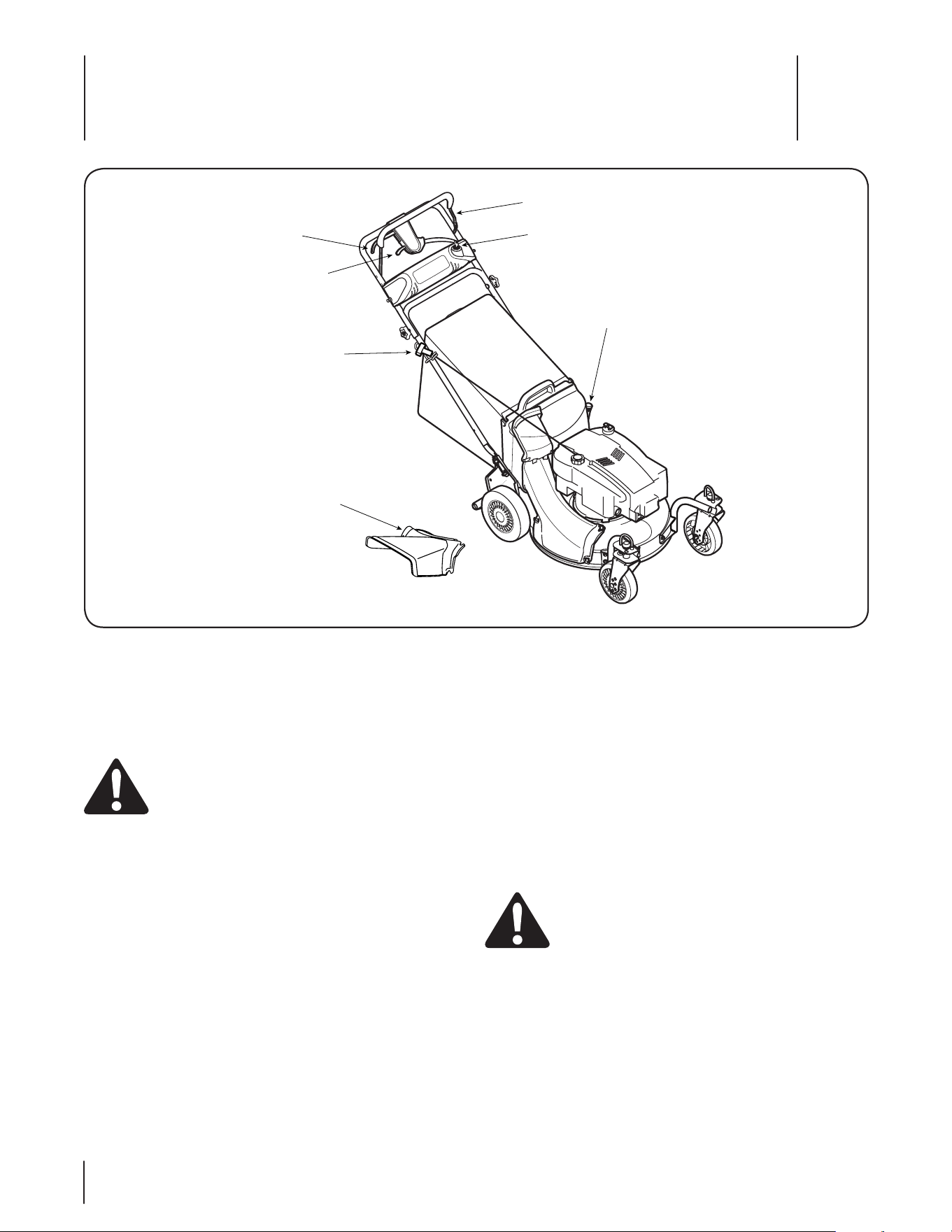
Controls and Features
4
12
Figure 4-1
Blade Control
The blade control is attached to the upper handle of the mower.
Depress and squeeze it against the upper handle to operate the
unit. Release it to stop engine and blade.
WARNING: This blade control is a safety device.
Never attempt to bypass its operations.
Cutting Height Adjustment Lever
The cutting height adjustment lever is located above the left
rear wheel. To adjust the cutting height, refer to the Assembly &
Set-Up section.
Drive Control
The drive control is located on the upper handle. Squeeze the
drive control to engage the drive system. Release it to disengage
the drive system.
Shift Lever
The shift lever is located on the drive control housing on the
upper handle. This lever is used to select the forward speed of
the mower. When changing speed selection, release the drive
control.
Recoil Starter
Shift Lever
Blade Control
Electric Start Ignition SwitchDrive Control
Cutting Height
Adjustment Lever
Side Discharge
Chute
IMPORTANT: Move the shift lever only when the engine is
running. Changing the shift lever setting with the engine off can
damage the mower.
Electric Start Ignition Switch
The electric start ignition switch is located on the left side of the
handle panel. It is used only for the electric starter.
Side Discharge Chute
Your mower is shipped as a mulcher. To discharge the grass
clippings to the side instead, follow the instructions in the
Assembly & Set-Up section to attach the side discharge chute.
WARNING: Keep hands and feet away from the
chute area on cutting deck. Refer to warning label
on the unit.
Recoil Starter
The recoil starter is connected to the support rod and is located
on the right side of the lower handle. Stand behind the unit and
pull the recoil starter rope to start the unit.
Operation
5
13
Figure 5-1
3
3
1
2
3
Starting Engine
WARNING: Be sure no one other than the operator
is standing near the lawn mower while starting
engine or operating mower. Never run engine
indoors or in enclosed, poorly ventilated areas.
Engine exhaust contains carbon monoxide, an
odorless and deadly gas. Keep hands, feet, hair and
loose clothing away from any moving parts on
engine and lawn mower.
Refer to engine manual for help with the engine.
Push primer (if equipped) three times. Wait about two 1.
seconds between each push. See Figure 5-1. In temperature
around 55° F or below, prime five times. Do not prime to
restart a warm engine.
Standing behind the mower, squeeze the blade control 2.
against upper handle.
Recoil Start:3. Holding these two handles together firmly,
grasp recoil starter handle and pull rope out with a rapid,
continuous, full arm stroke. See Figure 5-1. Keeping a firm
grip on the starter handle, let the rope rewind slowly.
Repeat until engine cranks. Let the rope rewind each time
slowly.
Electric Start: Turn ignition key to the right to start the
engine. Release the key after the engine starts.
Stopping Engine
Release blade control to stop the engine and blade.1.
WARNING: Wait for the blade to stop completely
before performing any work on the mower or to
remove the side discharge chute.
Using Your Lawn Mower
Be sure lawn is clear of stones, sticks, wire, or other objects
which could damage lawn mower or engine. Such objects could
be accidently thrown by the mower in any direction and cause
serious personal injury to the operator and others.
WARNING: If you strike a foreign object, stop the
engine. Remove wire from the spark plug,
thoroughly inspect mower for any damage, and
repair damage before restarting and operating.
Extensive vibration of mower during operation is an
indication of damage. The unit should be promptly
inspected and repaired.
Using as Mulcher
For mulching grass, remove the grass catcher and the side
discharge chute from the mower. For effective mulching, do not
cut wet grass. If the grass has been allowed to grow in excess of
four inches, mulching is not recommended. Use the grass catcher
to bag clippings instead.
WARNING: The operation of any lawn mower can
result in foreign objects being thrown into the eyes,
which can damage your eyes severely. Always wear
safety glasses while operating the mower, or while
performing any adjustments or repairs on it.
Using Grass Catcher
You can use the grass catcher bag to collect clippings while
you are operating the mower. The grass bag is equipped with
a bag-fill indicator to add convenience to your work. While the
mower is running, air will flow through the bag and into the
Grass Gauge. If the grass catcher is empty, air flows through
easily pushing the gauge up. If the grass catcher is full, air does
not flow through it allowing the gauge to fall. So the position of
the gauge acts as a bag-fill indicator signifying when to empty
the grass bag.
Attach grass catcher following instructions in “Setup and 1.
Adjustment”. Grass clippings will automatically collect in
the bag as you run the mower.
Operate the mower till the grass bag is full.2.
Stop engine completely by releasing the blade control. 3.
Make sure that the unit has come to a complete stop.
While holding the grass bag by both the rear handle and 4.
the lower handle, lift the grass bag straight up off the
adapter. The chute door will move the rope out of the way
of the bag.
Continue to hold the lower handle and raise the rear of the 5.
grass bag up toward your chest. The grass bag will open
and the grass clippings will disperse. When replacing the
grass bag, be sure the top of the bag rests on the wire
support between the handles.
Maintenance & Adjustments
6
14
Figure 6-1
Maintenance
General Recommendations
Always observe safety rules when performing any •
maintenance.
The warranty on this lawn mower does not cover items that •
have been subjected to operator abuse or negligence. To
receive full value from warranty, operator must maintain
the lawn mower as instructed here.
Changing of engine-governed speed will void engine •
warranty.
All adjustments should be checked at least once each •
season.
Periodically check all fasteners and make sure these are •
tight.
WARNING: Always stop engine, disconnect spark
plug, and ground against engine before performing
any type of maintenance on your machine.
Lubrication
Lubricate pivot points on the blade control at least once a 1.
season with light oil. The blade control must operate freely
in both directions. See Fig. 6-1.
Lubricate the wheels and casters at least once a season 2.
with light oil (or motor oil). If wheels are removed for any
reason, lubricate the axle bolt and inner surface of the
wheel with light oil. See Fig. 6-1.
Lubricate the torsion spring and pivot point on each end of 3.
the grass catcher adapter door at least once a season with
light oil to prevent rust. See Fig. 6-1.
The transmission is pre-lubricated and sealed at the factory 4.
and does not require lubrication.
Follow the accompanying engine manual for lubrication 5.
schedule and instruction for engine lubrication.
Deck Care
Clean underside of the mower deck after each use to prevent
build-up of grass clippings or other debris. Follow steps below
for this job.
Disconnect spark plug wire. Drain gasoline from lawn 1.
mower or place a piece of plastic under the gas cap.
Tip mower so that it rests on the housing. Keep the side 2.
with the air cleaner facing up. Hold mower firmly.
WARNING: Never tip the mower more than 90º in
any direction and do not leave the mower tipped for
any length of time. Oil can drain into the upper part
of the engine causing a starting problem.
3. Scrape and clean the underside of the deck with a suitable
tool. Do not spray with water.
IMPORTANT: Do not use a pressure washer or garden hose
to clean your unit. These may cause damage to bearings,
or the engine. The use of water will result in shortened life
and reduce serviceability.
4. Put the mower back on its wheels on the ground. If you had
put plastic under the gas cap earlier, make sure to remove it
now.
15se c t i O n 6 — Ma i n t e n a n c e & ad j u s t M e n t s
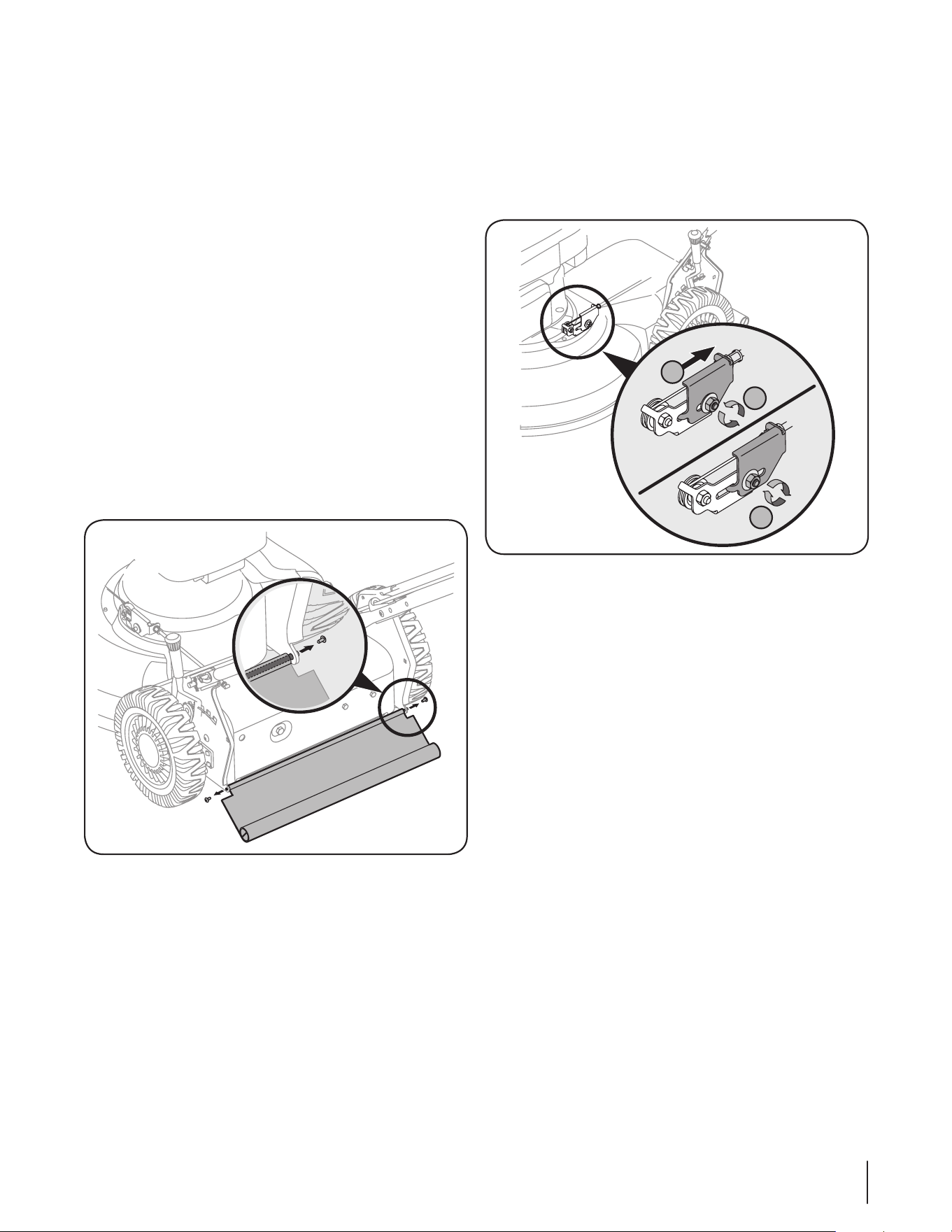
Adjustments
Shift Lever Cable
Periodic adjustment of the six speed shift cable may be necessary
due to normal wear on the cable. Adjustment is needed if all six
speeds do not work. The adjustable cable bracket is located on
the left side of the mower beside the engine. See Fig. 6-3.
Start engine and place shift lever in the sixth speed 1.
position.
Stop engine and disconnect spark plug wire and ground it 2.
against engine.
Loosen hex nut which secures the adjustable cable bracket. 3.
See Fig. 6-3.
Push back on the adjustable cable bracket.4.
Tighten hex nut.5.
Engine Care
A list of key engine maintenance jobs required for good
performance by the mower is given below. Follow the
accompanying engine manual for a detailed list and instructions.
Maintain oil level as instructed in engine manual.•
Service air cleaner every 25 hours under normal conditions. •
Clean every few hours under extremely dusty conditions.
Poor engine performance and flooding usually indicates
that the air cleaner should be serviced. To service the air
cleaner, refer to the engine manual.
Clean spark plug and reset the gap once a season. Spark •
plug replacement is recommended at the start of each
mowing season. Check engine manual for correct plug
type and gap specifications.
Clean engine regularly with a cloth or brush. Keep the •
top of the engine clean to permit proper air circulation.
Remove all grass, dirt, and combustible debris from muffler
area.
Replacing Rear Flap
To replace rear flap, proceed as follows:
To remove rear flap, lift rear door, remove screw, and press 1.
flap in on either side to remove from hole. See Fig. 6-2.
Remove screw and flap from opposite hole and replace 2.
with new flap in the opposite order and manner of
removal.
3
4
5
Figure 6-2
Figure 6-3
Service
7
16
WARNING: An unbalanced blade will cause
excessive vibration when rotating at high speeds. It
may cause damage to mower and could break
causing personal injury.
5. Lubricate the engine crankshaft and the inner surface of
the blade adapter with light oil. Slide the blade adapter
onto the engine crankshaft. Place the blade on the adapter
such that the side of the blade marked “Bottom” (or with
part number) faces the ground when the mower is in the
operating position. Make sure that the blade is aligned and
seated on the blade adapter flanges.
6. Place blade bell support on the blade. Align notches on the
blade bell support with small holes in blade.
7. Replace hex bolt and tighten hex bolt to torque: 450 in. lbs.
min., 600 in. lbs. max.
To ensure safe operation of your mower, periodically check the
blade bolt for correct torque.
Belt Care
NOTE: Several components must be removed in order to change
the mower’s belt. See an authorized Cub Cadet Service Dealer to
have your belt replaced.
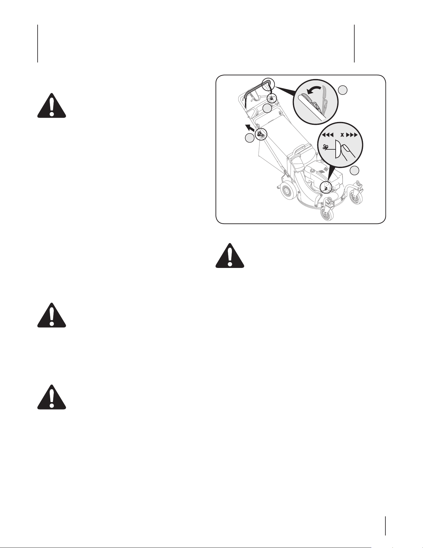
Replacing Battery
WARNING: Batteries contain sulfuric acid which
may cause burns. Do not short circuit or mutilate
batteries in any way. Do not put batteries in fire as
these may burst or release toxic materials.
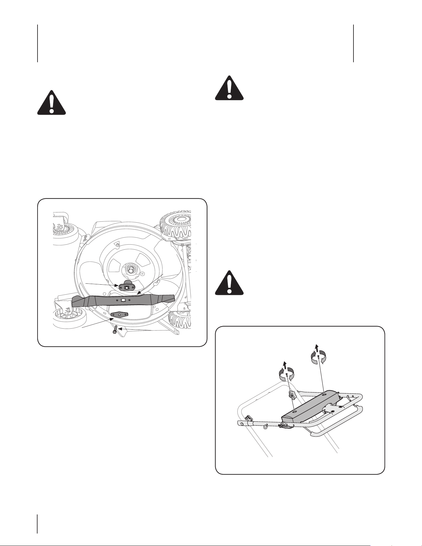
Loosen star knobs securing upper and lower handles and 1.
carefully fold the upper handle down toward the lower
handle as shown in Fig. 7-2.
Blade Care
WARNING: When removing the cutting blade for
sharpening or replacement, protect your hands with
a pair of heavy gloves or use a heavy rag to hold the
blade.
Periodically inspect the blade adapter for cracks, especially if you
strike a foreign object. Replace when necessary. Follow the steps
below for blade service.
Disconnect spark plug boot from spark plug. Turn mower 1.
on its side making sure that the air filter and the carburetor
are facing up.
Remove the bolt and the blade bell support which hold the 2.
blade and the blade adapter to the engine crankshaft. See
Fig. 7-1.
NOTE: When removing the blade, blade adapter, etc., be
careful not to remove or lose parts above it associated with
the engine pulley.
Remove blade and adapter from the crankshaft. See Fig. 3.
7-1.
Remove blade from the adapter for testing balance. 4.
Balance the blade on a round shaft screwdriver to check.
Remove metal from the heavy side until it balances evenly.
When sharpening the blade, follow the original angle of
grind. Grind each cutting edge equally to keep the blade
balanced.
Blade
Blade
Adapter
Bolt
Blade Bell
Support
Figure 7-1
Figure 7-2
17se c t i O n 7 — se r v i c e
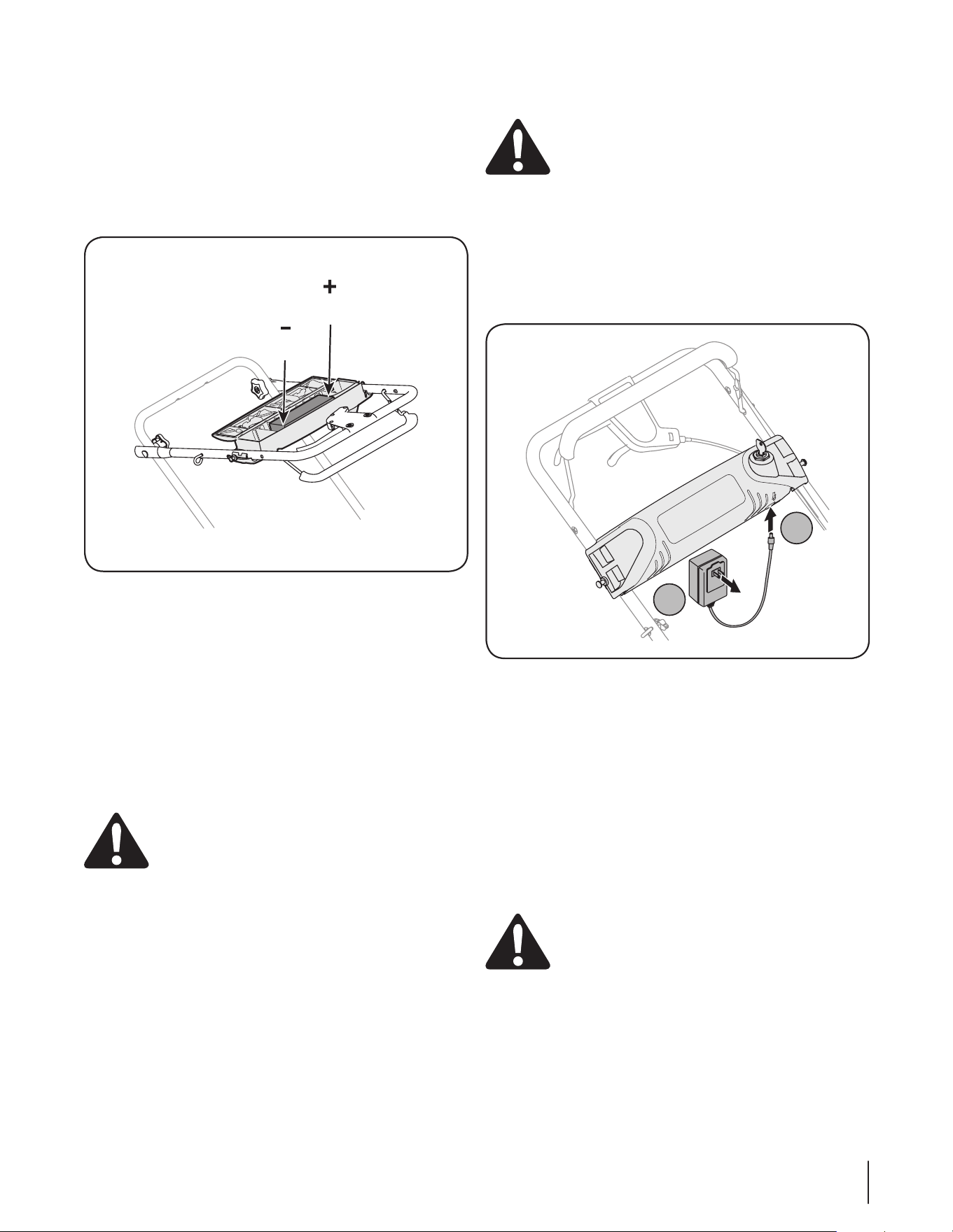
Remove the two screws securing battery cover to battery 2.
housing and place them to the side. See Fig. 7-2.
Open battery cover, remove positive and negative leads 3.
from battery, remove and replace with new battery.
Connect the positive lead to the positive side of the battery
pack, then connect the negative side.
NOTE: The battery you have may differ slightly from the
one shown in Fig. 7-3. Refer to the Parts List.
IMPORTANT: When replacing battery pack in handle panel,
battery pack must be positioned with the positive terminal
to the left side and the negative terminal to the right side
of panel (Positive terminal is closest to the key switch).
See Fig. 7-3. Replacing battery pack incorrectly will cause
serious damage.
Reattach battery cover to battery housing by securing with 4.
the two screws removed earlier, making sure to snap the
wire conduit on the left into place on the housing.
Fold handles back up and tighten star knobs.5.
WARNING: Do not remove the battery pack from
the electric starter housing for any reason other
than replacement.
Charging Battery
WARNING: The battery contains corrosive fluid
and toxic material; handle with care and keep away
from children. Do not puncture, disassemble,
mutilate or incinerate the battery. Explosive gases
could be vented during charging or discharging. Use
in a well ventilated area, away from sources of
ignition.
NOTE: The special designed plug on the charger will only
fit into the plug on the battery box.
Plug the battery charger into the port on the underside of 1.
the battery housing. See Fig. 7-4.
Insert the battery charger plug into a standard 120 volt 2.
household outlet. Charge battery for 8 to 10 hours before
initial use. Do not charge longer than 12 hours. The
battery should only need to be charged upon initial setup
and after any other extended periods of non-use.
After charging, disconnect charger plug from outlet first, 3.
then disconnect charger lead from battery.
IMPORTANT: Always plug charger lead into battery pack
lead first, and then insert battery charger plug into 120
volt standard household outlet. Follow this order of action
every time you charge the battery.
WARNING: Use only the battery charger supplied
with this mower.
Negative
Terminal
Positive
Terminal
Figure 7-3
1
2
Figure 7-4
18 se c t i O n 7— se r v i c e
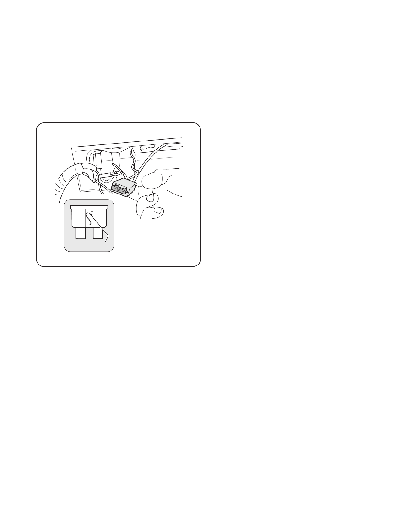
Replacing Fuse
The electric starter circuit and battery are protected by a 40
ampere fuse. If the fuse burns out, the electric starter will not
operate. If the unit fails to start with the electric starter, perform
the following steps to check the fuse inside the battery housing:
Open the battery cover as described in Replacing Battery. 1.
See Fig. 7-2.
Remove fuse from socket and inspect as shown in Fig. 7-5. 2.
If it is burned out, replace with standard automotive 40
ampere fuse.
Carefully place wiring back into housing, close battery 3.
cover, and fold upper handle back into place.
NOTE: The engine can be started manually if the fuse burns
out.
Off-Season Storage
The following steps should be taken to prepare your lawn mower
for storage.
Clean and lubricate mower thoroughly as described in the •
lubrication instructions.
Do not use a pressure washer or garden hose to clean your •
unit.
Coat mower’s cutting blade with chassis grease to prevent •
rusting.
Refer to engine manual for correct engine storage •
instructions.
Store mower in a dry, clean area. Do not store next to •
corrosive materials, such as fertilizer.
When storing any type of power equipment in a poorly
ventilated or metal storage shed, care should be taken to
rust-proof the equipment. Using a light oil or silicone, coat the
equipment, especially cables and all moving parts of your lawn
mower before storage.
Battery
The battery must be stored with a full charge. Extended storage
of a discharged battery will reduce life and capacity of the
battery.
Blown Fuse
Figure 7-5

Troubleshooting
8
19
Problem Cause Remedy
Engine Fails to start Blade control disengaged.1.
Spark plug boot disconnected.2.
Fuel tank empty or stale fuel.3.
Engine not primed (if equipped with primer). 4.
Faulty spark plug.5.
Blocked fuel line.6.
Engine flooded. 7.
Fuel valve (if equipped) closed.8.
Engine not choked (if equipped with choke).9.
Burnt fuse. (Electric Start only)10.
Engage blade control.1.
Connect wire to spark boot.2.
Fill tank with clean, fresh gasoline.3.
Prime engine as instructed in the Operation 4.
section.
Clean, adjust gap, or replace.5.
Clean fuel line.6.
Wait a few minutes to restart, but do not 7.
prime.
Open fuel valve. See engine manual.8.
Choke engine. See engine manual.9.
Replace fuse (see Service Section).10.
Engine runs erratic Spark plug boot loose.1.
Blocked fuel line or stale fuel. 2.
Vent in gas cap plugged.3.
Water or dirt in fuel system.4.
Dirty air cleaner.5.
Unit running with CHOKE (if equipped) 6.
applied.
Connect and tighten spark plug boot.1.
Clean fuel line; fill tank with clean, fresh 2.
gasoline.
Clear vent.3.
Drain fuel tank. Refill with fresh fuel.4.
Refer to engine manual.5.
Push CHOKE knob in.6.
Engine overheats Engine oil level low.1.
Air flow restricted.2.
Fill crankcase with proper oil.1.
Clean area around and on top of engine.2.
Occasional skips
(hesitates) at
high speed
Spark plug gap too close.1. Adjust gap to .030”.1.
Idles poorly Spark plug fouled, faulty, or gap too wide.1.
Dirty air cleaner.2.
Reset gap to .030” or replace spark plug.1.
Refer to engine manual.2.
Excessive Vibration Cutting blade loose or unbalanced.1.
Bent cutting blade.2.
Tighten blade and adapter. Balance blade.1.
See an authorized service dealer.2.
Mower will not
mulch grass
Wet grass. 1.
Excessively high grass. 2.
Dull blade.3.
Do not mow when grass is wet; wait until 1.
later to cut.
Mow once at a high cutting height, then 2.
mow again at desired height or make a
narrower cutting path.
Sharpen or replace blade.3.
Continued on next page

20 Se c t i o n 8 — tr o u b l e S h o o t i n g
Problem Cause Remedy
Uneven cut Wheels not positioned correctly. 1.
Dull blade.2.
Place all four wheels in same height position 1.
(if equipped with individual height adjusters).
Sharpen or replace blade.2.
Mower will not self propel Belt not installed properly. 1.
Debris clogging drive operation. 2.
Damaged or worn belt.3.
Check belt for proper pulley installation and 1.
movement.
Stop engine, disconnect spark plug boot, 2.
and clean out debris.
Inspect and replace belt.3.

Notes
9
21
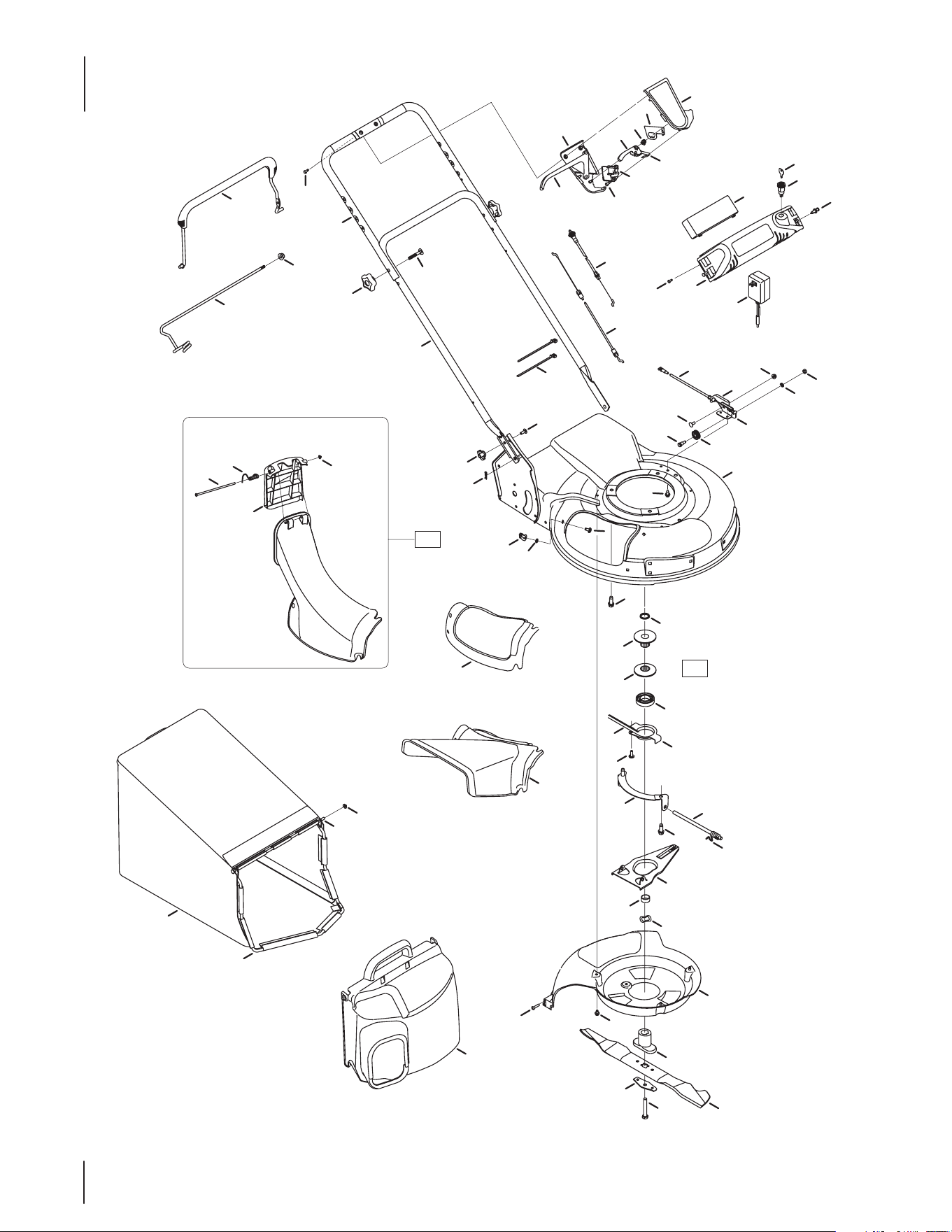
22
Model Series 990
34
41
44
49
47
48
45
40
5
1
43
33
32
38
42
39
57
21
51
54
58
20
46
22
24
23
11
7
2
10
9
8
50
64
73
525
65
22
17
13
12
25
23
14
27
28
37
23
36
19
53
55
56
30
29
26
16
67
62
66
59
61
15
3
4
5
6
68
71
70
69
63
60
72
18
51
31
35

23
Ref
No.
Part Number Description
1 647-04008 Blade Control
2 753-0717 Upper Control Housing†
3 731-0620A Drive Control
4 753-0717 Lower Control Housing†
5 710-1667A C Sunk Tap Screw, #10 x.75 Lg
6 753-0717 Cable Mounting Cap†
7 74 6 - 0711B Drive Cable
8 728-0199 Rivet
9 925-04347 Key Switch
10 925-0201 Key
11 746 -04530 Control Cable
12 749-04354A-0637 Upper Handle
13 720-04072 Star Knob
14 710-1652 Screw, 1/4-20 x .625
15 710 -1174 Carriage Bolt, 5/16-18 x 2.0
16 926-0240 Cable Tie
17 749 -0907B Lower Handle
18 931-0066 Adapter Assembly
19 731-1832 Side Discharge Chute
20 931-1833A Mulch Cover
21 782-0078B-4021 Deck 21”
22 912- 0397 Wing Nut
23 710-0703 Carriage Bolt, 1/4-20 x .75”
24 914-0104 Cotter Pin
25 726-0233 Push Nut, .25 x ID x .50 OD
26 950-1071 Sleeve Spacer, .88ID x 1.13OD
27 756-0612A Half Pulley: 2.62 OD
28 756-0613 Half Pulley: 2.62 OD x 1.61
29 741-0545 Ball Bearing
30 682-7527 Cup
31 748-0377C Blade Adapter
32 736-0524B Blade Bell Support
33 710 -1257 Hex Bolt, 3/8-24 x 2.5
34 742-04276S 21” Mulching Blade
35 710-0653 Screw, 1/4-20 x 3.75
36 731-1828 Bae
37 954-0460 Belt, 3/8 x 39.24
Ref
No.
Part Number Description
38 710-0895 Screw, 1/4-15 x .750
39 664-0180 Grass Catcher
40 747-0940A-0637 Support Rod w/ Rope Guide
41 747-0939 Pivot Rod
42 747-0937-0637 Grass Catcher Frame
43 631-0071 Grass Catcher Cover
44 926-0106 Cap Nut
45 712- 04063 Flange Lock Nut, 5/16-18
46 731-1874A Chute Door
47 732-0819 Torsion Spring
48 72 6 - 0111 Push Cap
49 747-0965 Pivot Rod
50 925-04323 12V Battery
51 710-0654A Sems Screw, 3/8-16 x 1.00
52 925-04072 Harness Assembly
53 936-0526 Wave Washer, 1.38 ID x.88 OD
54 950-1070 Slve Spacer, .88 ID x 1.00 OD
55 782-7596A Control Arm
56 932-0807 Torsion Spring
57 711 -1114 Pivot Shaft
58 782-7597 Pivot Bracket
59 738-0924A Shlder Screw, .375 ID x 1/4-14
60 756-0625 Cable Roller
61 710-0134 Carriage Screw, 1/4-20 x .62
62 936-0329 Lock Washer, 1/4
63 782-7575B-0637 Cable Mounting Bracket
64 746-0939A 6 Speed Cable
65 782-7574A-0637 Cable Adjustment Bracket
66 712-04064 Hex Nut 1/4-20
67 912-0138 Hex Nut 1/4-28
68 732-0627 Shift Lever Spring
69 731-0924 6 Speed Shift Lever
70 913-0397 Gear Insert
71 16864 6 Spd. Rack Cable Bracket
72 956 -0613A Pulley Assembly
73 725-04329 12V Battery Charger
Model Series 990
† Only available as part of this kit
24
42
1
40
44
2
37
59
32
31
41
39
7
9
6
10
11
13
30
23
38
35
36
34
47
23
27
29
30
28
26
45
48
24
25
23
22
21
20
12
13
14
6
56
18
53
17
55
15
16
56
19
50
54
4
49
51
52
55
33
58
57
3
5
46
48
23
14
12
8
43
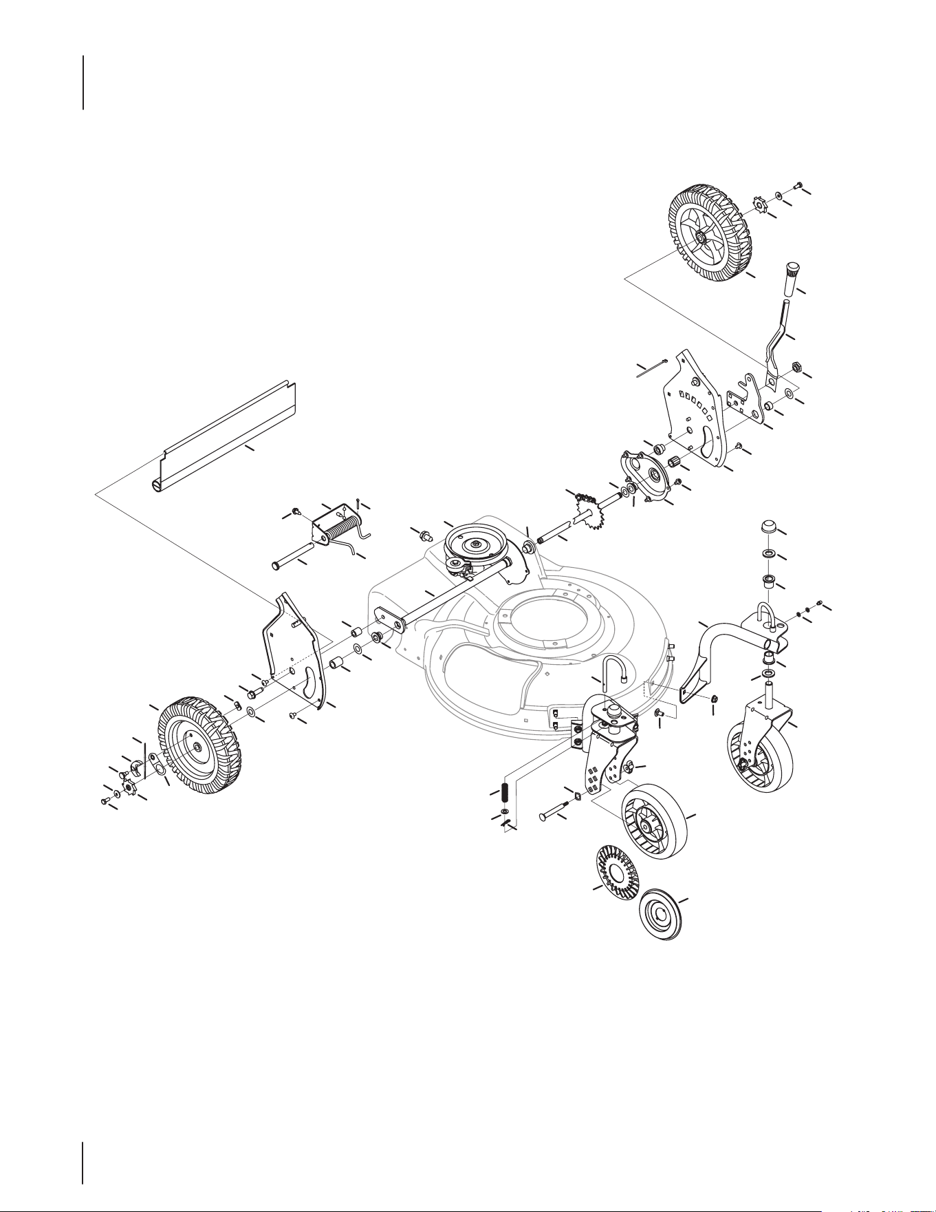
Model Series 990

25
Ref
No.
Part Number Description
1 914-0474 Cotter Pin
2 710-1652 Screw 1/4-14 x .825
3 936-0264 Flat Washer.330 ID x.630 OD
4 914-0104 Cotter Pin
5 932-0306A Compression Spring
6 734-2010 Wheel, 9 x 2.125
7 912- 0414 Top Lock Tab Weld Nut 1/4-20
8 16855 Ratchet Pawl Plate
9 10622B Plastic Spring Ratchet
10 748-0381 Pawl RH
948-0188B Pawl LH
11 938-0137A Shlder Screw.340 ID x.285 OD
12 948-0318 Wheel Ratchet
13 736-0270 Bell Washer.265 ID x.75 OD
14 710-0751 Hex Cap Screw 1/4-20 x.620
15 937-3000 Grease Fitting
16 736-0931 Flat Washer.203 ID x.403 OD
17 747-0924 Wheel Pin Lock
18 682-9020A-0691 Caster Assembly RH
682-9021A-0691 Caster Assembly LH
19 682-9024-0691 Caster Bracket Assembly RH
682-9026-0691 Caster Bracket Assembly LH
20 720-0223 Grip
21 732-0803A Spring Lever
22 938-0529 Shoulder Nut.825 x .165 Lg.
23 936-0369 Flat Washer .508 ID x 1.0 OD
24 782-0566B-0637 Pivot Arm Assembly
25 750-0515 Spacer .510 ID x .70 OD
26 741-0978 Slv Bearing .504 ID x .830 OD
27 950-1056 Shlder Spacer, .385ID x .715Lg
28 710-0653 Tap Screw 1/4-20 x .375
Ref
No.
Part Number Description
29 682-7528-0637 Chain Cover Assembly
30 741- 0324A Flge Bearing .506 ID x .590 Lg
31 682-7526-0637 Transmission Axle Assembly
32 918-0263A Transmission Ass’y Complete
33 734-1857 Wheel 7 x 2
34 913- 0453 Chain
35 638-0012 Rear Axle Assembly
36 941-0522 Flge Bearing .506 ID x .715 Lg
37 782-0568-0637 Height Adjustment Spring Brkt.
38 950-0151 Spacer .550 ID x .750 OD
39 710-1315 Screw 3/8-16 x .25
40 911 - 0 835 Clevis Pin .50 Dia x 4.82 Lg.
41 750-0807 Spacer .385 ID x .624 OD
42 732-0832 Torsion Spring
43 710-0779A Screw, AB, #10-16 x .500
44 731- 06874 Trail Shield
45 687-02495 Handle Bracket Assembly - LH
46 687-02494 Handle Bracket Assembly - RH
47 725-0157 Cable Tie
48 710 -1348 Screw 1/4-14 x.500
49 710-0260A Carriage Bolt 5/16-18 x.62
50 911 -114 6 Caster Axle
51 912- 0397 Wing Nut
52 712- 04063 Flange Lock Nut 5/16-18
53 726-0214 Push Cap
54 936-0232 Wave Washer.531 ID x.781 OD
55 736-0366 Flat Washer.640 ID x 1.12 OD
56 741-0685 Flange Bearing
57 731-1888 Hubcap - Spoke w/ Hole
58 731-0982C Hubcap - Radial Spoke
59 710-0604A Screw, 5/16-18 x .625
Model Series 990
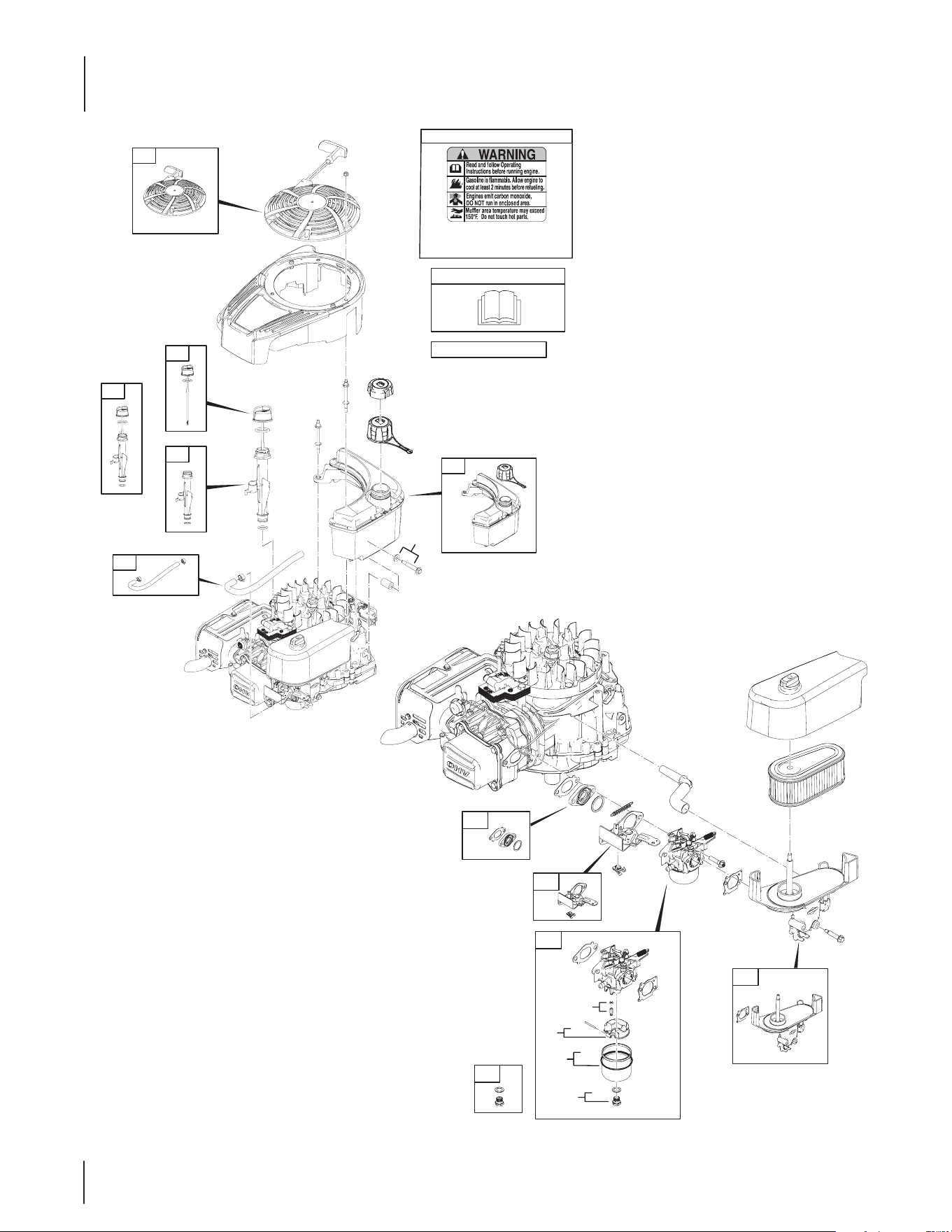
26
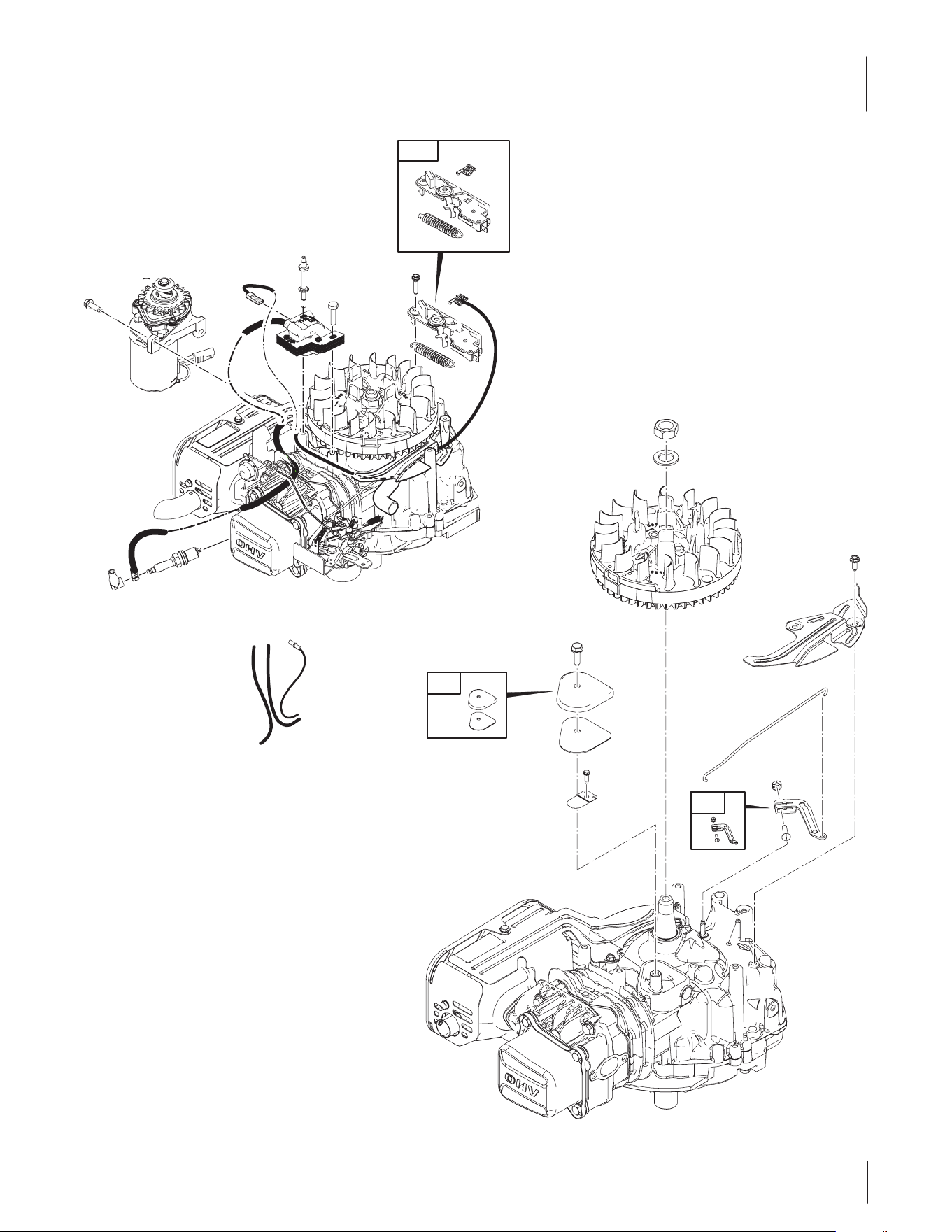
B&S Engine Model 12S905-0707-B1
608
592
304
523
842
670
972
957
847
525
524
1059
662A
957A
601
187
60
58
662A
875
133
104
125
118
122
51
623
209
11
621
365
445
968
163
1395
222
105
975
137
117
276
1036 EMISSIONS LABEL
1058 OPERATOR’S MANUAL
REQUIRED when replacing parts
with warning labels axed.
1319 WARNING LABEL
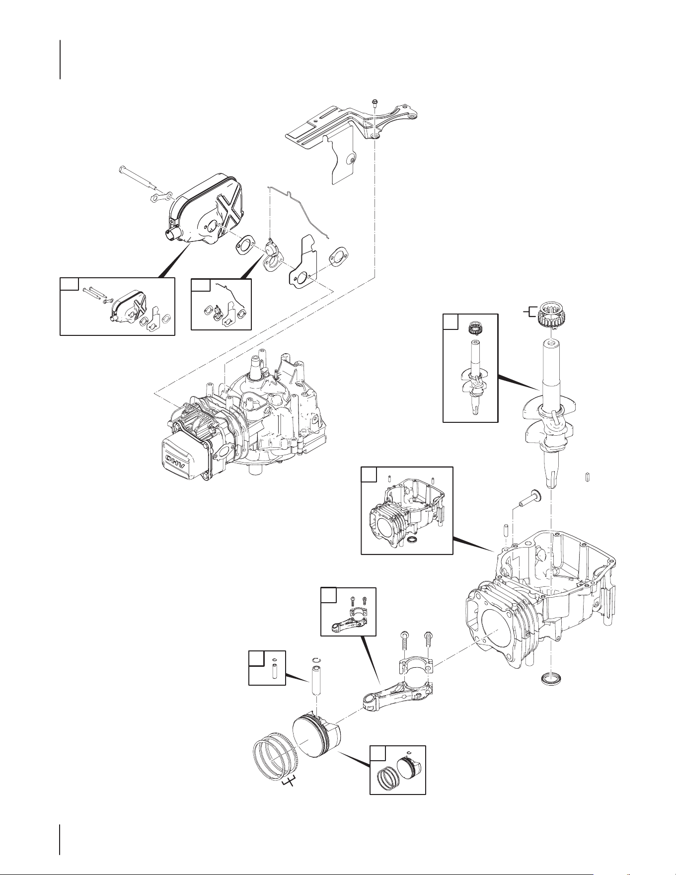
27
B&S Engine Model 12S905-0707-B1
365
309
635
337
789
1375
1376
23
75
332
78
37
202
505
227
562
1430
1263
1264
356
662
334
923
745
922
333
621
697
28
B&S Engine Model 12S905-0707-B1
613
81
300
291
883
883A
216
883
16
1
29
27
28
32A
32
3
25
26
718
45
24
741
306
307
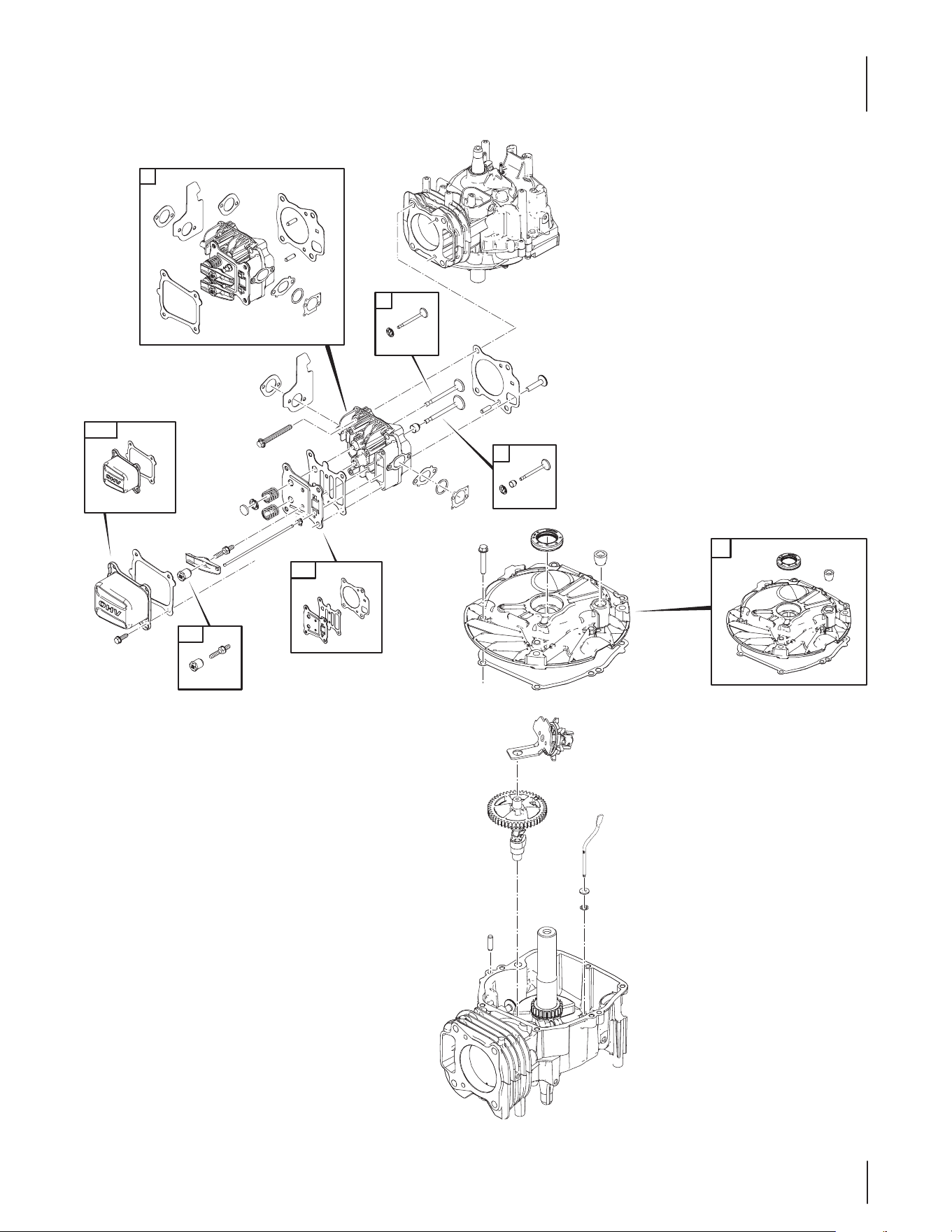
29
B&S Engine Model 12S905-0707-B1
1023
883
883A
13
993
36
40
238
35
1034
1026
886
22
12
43
46
616
404
615
718
20
15
4
830
1029
1022
914
192
5
33
34
45
718
868
7
51
623
163
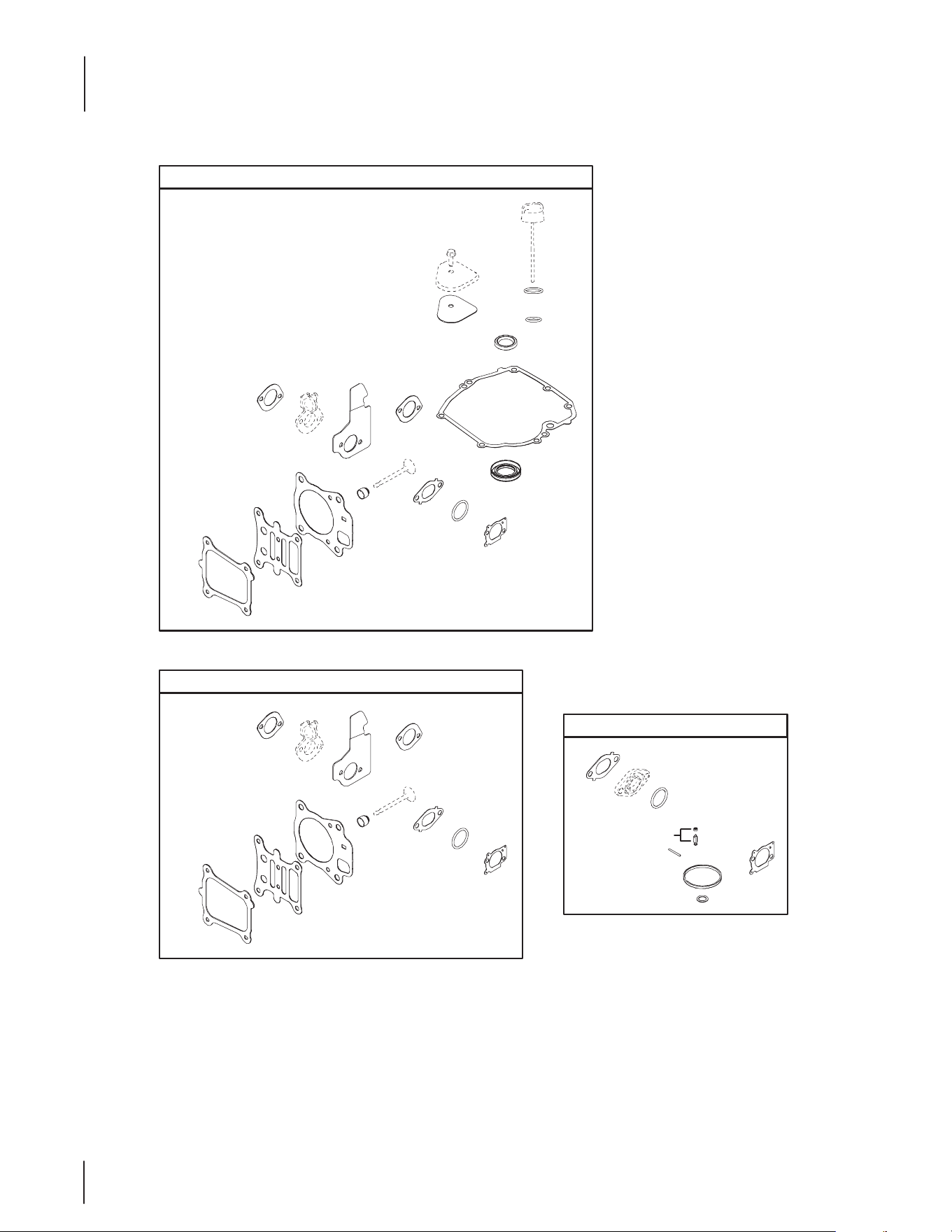
30
1430
842
524
3
12
883
883A
883
993
7
1022
868
51
623
163
20
1095 VALVE GASKET SET
883
868
51
623
163
883A
7
883
993
1022
105
104
137
276
163
51
623
358 ENGINE GASKET SET
121 CARBURETOR OVERHAUL KIT
B&S Engine Model 12S905-0707-B1

31
B&S Engine Model 12S905-0707-B1
Ref.
Part Number Description
1 BS-796509 Cylinder Assembly
3 BS-299819S Seal-Oil
4 BS-493279 Sump-Engine
5 BS-796471 Head-Cylinder
7 BS-796475 Gasket-Cylinder Head
11 BS-796478 Tube-Breather
12 BS-692232 Gasket-Crankcase
13 BS-793451 Screw
15 BS-691680 Plug-Oil Drain
16 BS-796469 Crankshaft
20 BS-399781S Seal-Oil
22 BS-691092 Screw
23 BS-796619 Flywheel
24 BS-222698S Key-Flywheel
25 BS-796639 Piston Assembly (Standard)
25 BS-796640 Piston Assembly (.020" Oversize)
26 BS-796641 Ring Set (Standard)
26 BS-796642 Ring Set (.020" Oversize)
27 BS-691588 Lock-Piston Pin
28 BS-298909 Pin-Piston
29 BS-796470 Rod-Connecting
32 BS-691664 Screw
32A BS-695759 Screw
33 BS-499642 Valve-Exhaust
34 BS-795443 Valve-Intake
35 BS-691304 Spring-Valve
36 BS-691304 Spring-Valve
37 BS-796536 Guard-Flywheel
40 BS- 692194 Retainer-Valve
43 BS-796650 Slinger-Governor/Oil
45 BS-690977 Tappet-Valve
46 BS-694039 Camshaft
51 BS-796596 Gasket-Intake
58 BS-697316 Rope-Starter
60 BS-281434S Grip-Starter Rope
75 BS-691736 Washer
78 BS-793480 Screw
81 BS- 69174 0 Lock-Muer Screw
104 BS-691242 Pin-Float Hinge
105 BS-398188 Valve-Float Needle
Ref.
Part Number Description
117 BS-697355 Jet-Main
118 BS-494870 Jet-Main
121 BS-796612 Kit-Carburetor Overhaul
122 BS-796595 Spacer-Carburetor
125 BS-796608 Carburetor
133 BS-398187 Float-Carburetor
137 BS-796610 Gasket-Float Bowl
163 BS-691894 Gasket-Air Cleaner
187 BS-796491 Line-Fuel
192 BS-796631 Adjuster-Rocker Arm
202 BS-796657 Link-Mechanical Governor
209 BS-796484 Spring-Governor
216 BS-796485 Link-Choke
222 BS-796482 Bracket-Control
227 BS-796487 Lever-Governor Control
238 BS-691300 Cap-Valve
276 BS-271716 Washer-Sealing
291 BS-796486 Thermostat
300 BS-796495 Muer-Exhaust
304 BS-796693 Housing-Blower
306 BS-796535 Shield-Cylinder
307 BS-793480 Screw
309 BS-795092 Motor-Starter
332 BS-690662 Nut
333 BS-796499 Armature-Magneto
334 BS-793454 Screw
337 BS-692051 Plug-Spark
356 BS-692390 Wire-Stop
358 BS-796661 Gasket Set-Engine
365 BS-793458 Screw
404 BS-690272 Washer
445 BS-795066 Filter-Air Cleaner Cartridge
505 BS-793515 Nut
523 BS-796503 Dipstick
524 BS-692296 Seal-Dipstick Tube
525 BS-796502 Tube-Dipstick
562 BS-793514 Bolt
592 BS-793481 Nut
601 BS-791850 Clamp-Hose
608 BS-796497 Starter-Rewind

32
Ref.
Part Number Description
613 BS-796496 Screw
615 BS-796674 Retainer-Governor Shaft
616 BS-796488 Crank-Governor
621 BS-692310 Switch-Stop
623 BS-793628 Seal-O Ring
635 BS-66538S Boot-Spark Plug
662 BS-796537 Stud
662A BS-793479 Stud
670 BS-793485 Spacer-Fuel Tank
697 BS - 6 91127 Screw
718 BS-690959 Pin-Locating
741 BS-795755 Gear-Timing
745 BS-698557 Screw
789 BS-792685 Harness-Wiring
830 BS-796472 Stud-Rocker Arm
842 BS-691031 Seal-O Ring
847 BS-796501 Dipstick/Tube Assembly
868 BS-795440 Seal-Valve
875 BS-796492 Base-Air Cleaner
883 BS-793497 Gasket-Exhaust
883A BS-796677 Gasket-Exhaust
886 BS-796474 Gasket Kit-Cylinder Head Plate
914 BS-794451 Screw
922 BS-692135 Spring-Brake
Ref.
Part Number Description
923 BS-796635 Brake
957 BS-796577 Cap-Fuel Tank
957A BS-692046 Cap-Fuel Tank
968 BS-796493 Cover-Air Cleaner
972 BS-796489 Tank-Fuel
975 B S -7 96 611 Bowl-Float
993 BS-796473 Gasket-Cylinder Head Plate
1022 BS-796480 Gasket-Rocker Cover
1023 BS-796479 Cover-Rocker Arm
1026 BS-796481 Rod-Push
1029 BS-691230 Arm-Rocker
1034 BS-691343 Guide-Push Rod
1036 Label-Emissions
1058 BS-278415 Manual-Operator's
1059 BS-793471 Kit-Screw/Washer
1095 BS-796662 Gasket Set-Valve
1263 BS-697124 Reed-Breather
1264 BS-793453 Screw
1319 BS-794467 Label-Warning
1375 BS-796476 Cover-Breather/Reed
1376 BS-794451 Screw
1395 BS-690349 Screw
1430 BS-796477 Gasket-Breather/Reed
B&S Engine Model 12S905-0707-B1

33

34

35

IMPORTANT: To obtain warranty coverage owner must present an
original proof of purchase and applicable maintenance records to the
servicing dealer. Please see the operator’s manual for information on
required maintenance and service intervals.
The limited warranty set forth below is given by Cub Cadet LLC with
respect to new merchandise purchased or leased and used in the
United States and/or its territories and possessions, and by MTD
Products Limited with respect to new merchandise purchased or leased
and used in Canada and/or its territories and possessions (either entity
respectively, “Cub Cadet”).
Cub Cadet warrants this product (excluding its Normal Wear Parts
and Batteries, as described below) against defects in material and
workmanship for a period of three (3) years, commencing on the date
of original retail purchase or lease and will, at its option, repair or
replace, free of charge, any part found to be defective in materials or
workmanship.
Normal Wear Parts are warranted to be free from defects in material and
workmanship for a period of thirty (30) days from the date of original
purchase or lease. Normal wear parts include, but are not limited to
items such as: belts, blades, blade adapters, grass bags and wheels.
Batteries have a one-year prorated limited warranty against defects in
material and workmanship, with 100% replacement during the first three
months. After three months, the battery replacement credit is based on
the months remaining in the twelve (12) month period dating back to the
original date of original sale or lease. Any replacement battery will be
warranted only for the remainder of the original warranty period.
This limited warranty shall only apply if this product has been operated
and maintained in accordance with the Operator’s Manual furnished with
the product, and has not been subject to misuse, abuse, commercial
use, neglect, accident, improper maintenance, alteration, vandalism,
theft, fire, water, or damage because of other peril or natural disaster.
Damage resulting from the installation or use of any part, accessory
or attachment not approved by Cub Cadet for use with the product(s)
covered by this manual will void your warranty as to any resulting
damage. In addition, Cub Cadet may deny warranty coverage if the
hour meter, or any part thereof, is altered, modified, disconnected or
otherwise tampered with.
HOW TO OBTAIN SERVICE: Warranty service is available, WITH PROOF
OF PURCHASE AND APPLICABLE MAINTENANCE RECORDS, through
your local authorized service dealer. To locate the dealer in your area:
In the U.S.A.:
Check your Yellow Pages, or contact Cub Cadet LLC at P.O. Box 361131,
Cleveland, Ohio 44136-0019, call 1-877-282- 8684
or log on to our website at www.cubcadet.com.
In Canada:
Contact MTD Products Limited, Kitchener, ON N2G 4J1, call 1-800-668-
1238 or log on to our website at www.mtdcanada.com.
Without limiting the foregoing, this limited warranty does not provide
coverage in the following cases:
a. The engine or component parts thereof. These items may carry a
separate manufacturer’s warranty. Refer to applicable manufactur-
er’s warranty for terms and conditions.
b. Routine maintenance items such as lubricants, filters, blade
sharpening, tune-ups, brake adjustments, clutch adjustments, deck
adjustments, and normal deterioration of the exterior finish due to
use or exposure.
c. Service completed by someone other than an authorized service
dealer.
d. Cub Cadet does not extend any warranty for products sold or
exported outside of the United States and/or Canada, and their
respective possessions and territories, except those sold through
Cub Cadet’s authorized channels of export distribution.
e. Replacement parts and\or accessories that are not genuine Cub
Cadet parts.
f. Transportation charges and service calls.
g. Cub Cadet does not warrant this product for commercial use.
There are no implied warranties, including without limitation any
implied warranty of merchantability or fitness for a particular
purpose. No warranties shall apply after the applicable period of
express written warranty above. No other express warranties beyond
those mentioned above, given by any person or entity, including a
dealer or retailer, with respect to any product, shall bind Cub Cadet.
The exclusive remedy is repair or replacement of the product as
set forth above. The terms of this warranty provide the sole and
exclusive remedy arising from the sale and/or lease of the products
covered hereby. Cub Cadet shall not be liable for any incidental or
consequential loss or damage including, without limitation, expenses
incurred for substitute or replacement lawn care services or for rental
expenses to temporarily replace a warranted product.
Some jurisdictions do not allow the exclusion or limitation of incidental
or consequential damages, or limitations on how long an implied
warranty lasts, so the above exclusions or limitations may not apply to
you.
In no event shall recovery of any kind be greater than the amount of the
purchase price of the product sold. Alteration of safety features of the
product shall void this warranty. You assume the risk and liability for
loss, damage, or injury to you and your property and/or to others and
their property arising out of the misuse or inability to use the product.
This limited warranty shall not extend to anyone other than the original
purchaser or to the person for whom it was purchased as a gift.
HOW LOCAL LAWS RELATE TO THIS WARRANTY: This limited warranty
gives you specific legal rights, and you may also have other rights that
vary in different jurisdictions.
CUB CADET LLC
MANUFACTURER’S LIMITED WARRANTY FOR
WALk-BEhIND MOWERS
Cub Cadet LLC, P.O. BOX 361131 CLEVELAND, OhIO 44136-0019, Phone: 1-877-282-8684
MTD Products Limited, kitchener, ON N2G 4J1, Phone: 1-800-668-1238
GDOC-100089 REV. A

