1
Installation and
Operation
Instructions
2M-Z23813 Rev. - 12-7-2020
is a registerd trademark of APW Wyott®, A Middleby Company. All rights reserved.
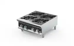
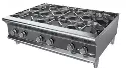
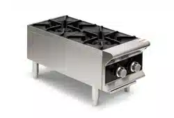
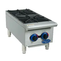
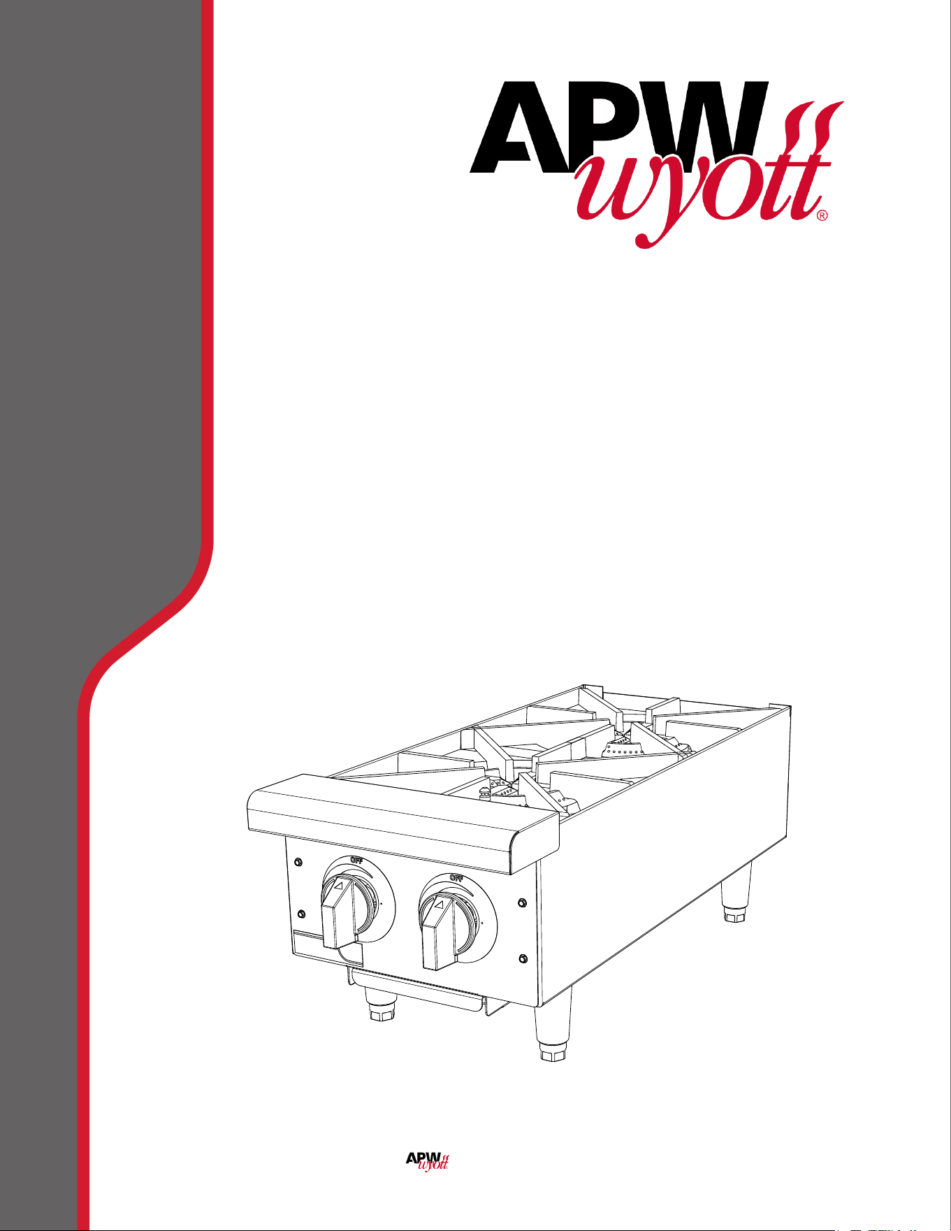
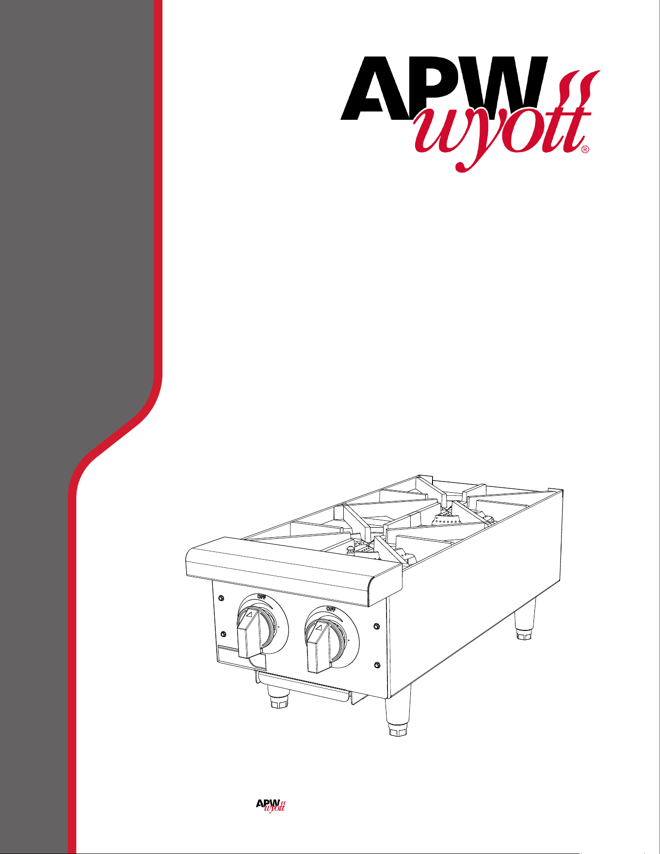
GAS HOT PLATES
Models
GHP-2S, GHP-4S, GHP-6S
1
1
2
2
3
3
4
4
5
5
6
6
7
7
8
8
A A
B B
C C
D D
SHEET 1 OF 1
DRAWN
CHECKED
QA
MFG
APPROVED
bnabors
12/7/2020
DWG NO
TITLE
SIZE
D
SCALE
REV
.75

2
2
These symbols are intended to alert the user to the presence of
important operating and maintenance instructions in the manual
accompanying the appliance.
RETAIN THIS MANUAL FOR FUTURE REFERENCE
NOTICE
Using any part other than genuine APW Wyott factory supplied parts relieves the
manufacturer of all liability.
APW Wyott reserves the right to change speci cations and product design
without notice. Such revisions do not entitle the buyer to corresponding changes,
improvements, additions or replacements for previously purchased
equipment.
Due to periodic changes in designs, methods, procedures, policies and
regulations, the speci cations contained in this sheet are subject to change
without notice. While APW Wyott exercises good faith e orts to provide
information that is accurate, we are not responsible for errors or omissions
in information provided or conclusions reached as a result of using the
speci cations. By using the information provided, the user assumes all risks in
connection with such use.
MAINTENANCE AND REPAIRS
Contact your local authorized service agent for service or required maintenance.
Please record the model number, serial number, voltage and purchase date in the area below and have it
ready when you call to ensure a faster service.
SAFETY SYMBOLS
Model No.
Serial No.
Voltage
Purchase Date
Business Hours: 8:00 am to 4:30 p.m. Central Standard Time
Telephone: (800) 527-2100
E-mail T[email protected]
Website: www.apwwyott.com
Mailing Address: APW Wyott
265 Hobson St
Smithville, TN 37166
U.S.A
The Service Help Desk
Authorized Service Agent Listing
Reference the listing provided with the unit
or
for an updated listing go to:
Website: www.apwwyott.com
E-mail T[email protected]
Telephone: (800) 527-2100
CAUTION WARNING
3
GENERAL INSTALLATION DATA
This equipment is designed and sold for commercial use only by personnel trained and experienced in
its operation and is not sold for consumer use in and around the home nor for use directly by the general
public in food service locations. For equipment to be used by the general public, please contact the factory.
This gas appliance is equipped for the types of gas indicated on the nameplate mounted on the front
panel. It is shipped adjusted for use on natural gas.
The installation of the Appliance should conform to the NATIONAL FUEL GAS CODE "ANSI
Z223.1 - LATEST EDITION" AND ALL LOCAL GAS COMPANY RULES AND REGULATIONS.
IN CANADA INSTALLATION SHALL BE IN ACCORDANCE WITH THE CURRENT
CAN/CGA-B149.1 NATURAL GAS INSTALLATION CODE OR CAN/CGA-B149.2
PROPANE INSTALLATION CODE AND LOCAL CODES WHERE APPLICABLE.
WARNING: Improper installation, adjustment, alteration, service or maintenance
can cause property damage, injury or death. Read the installation, operating and
maintenance instructions thoroughly before installing or servicing the equipment.
FOR YOUR SAFETY
DO NOT STORE OR USE GASOLINE OR OTHER FLAMMABLE VAPORS AND LIQUIDS IN
THE VICINITY OF THIS OR ANY OTHER APPLIANCE. KEEP THE APPLIANCE AREA CLEAR
AND FREE FROM COMBUSTIBLES.
This appliance, its pressure regulator and its individual shuto valve must be disconnected from the gas
supply piping system during any pressure testing of that system at test pressures in excess of 1/2 PSIG.
This appliance and its pressure regulator must be isolated from the gas supply piping system by closing
its individual manual shuto valve during any pressure testing of the gas supply piping system at test
pressures equal to or less than 1/2 PSIG. For your protection, we recommend a qualied installing agency
install this appliance. They should be familiar with gas installations and your local gas requirements. In
any case, your gas company should be called to approve the nal installation. In addition, there should
be posted, in a prominent location, detailed instructions to be followed in the event the operator smells
gas. Obtain the instructions from the local gas supplier.
LEVELING UNIT
Units are shipped with feet detached. To attach feet, remove the grates, lay unit on it's side and screw
feet into sockets on bottom. Level unit by adjusting the (4) feet which have an adjustment of 1-3/4" for
accurate and perfect line-up with other Star-Max series units.
DO NOT REMOVE FEET.
GAS PIPING
Gas piping shall be new, clean and of such size and so installed as to provide a supply of gas sucient
to meet the full gas input of the appliance. If the appliance is to be connected to existing piping, it shall be
checked to determine if it has adequate capacity. Joint compound (pipe dope) shall be used sparingly and
only on the male threads of the pipe joints. Such compounds shall be resistant to the action of L.P. gases.
WARNING: Any loose dirt or metal particles which are allowed to enter the gas lines on the appliance will
damage the automatic valve and aect its operation. When installing this appliance, all pipe and ttings
must be free from all internal loose dirt.

4
CLEARANCE
Minimum wall clearances for the sides and back of the models contained in this manual shall be as follows:
Combustible Non-Combustible
Wall Wall
Hotplates 9" 0"
PRESSURE REGULATOR
A convertible pressure regulator set at 6" water column for use on natural gas is furnished. (For LP models
the regulator is set for 10" water column pressure.) Attach the regulator to the supply pipe, located at
the back of the unit, make sure gas ow arrow on regulator is pointing towards manifold. The gas supply
is then connected to the regulator. A 1/8" tap is furnished on the manifold for checking pressure. The
manifold is accessible by removing the front panel.
MANUAL SHUT OFF VALVE
A manual shut o valve should be installed upstream from the unit and within six feet of the appliance,
and is not provided.
CONNECTING GAS SUPPLY LINE
The gas inlet on this appliance is sealed at the factory to prevent entry of dirt. Do not remove this seal
until the actual connection is made to the gas supply line.
CHECKING FOR GAS LEAKS
Soap and water solution or other material acceptable for the purpose, shall be used in locating gas leakage.
Matches, candle ame or other sources of ignition shall not be used for this purpose.
AIR SUPPLY
Provisions for adequate air supply must be furnished.
AIR INTAKES IN BOTTOM
Make certain the air intake openings in the bottom of the appliance are not obstructed. They are
essential for proper combustion and operation of the appliance.
EXHAUST CANOPY
It is essential that facilities be provided to carry o fumes and gases.
GAS INPUT OF OPEN TOP RANGES
For Natural Gas: Regulator output pressure set at 6" water column.W
For Propane Gas: Regulator output pressure set at 10" water column.
Note: The appliance is equipped with natural gas orice hoods. A separate set of hoods will
be provided for use on propane gas. The propane hoods are located on the front panel.
Factory set LP models do not include the natural gas hoods.
5
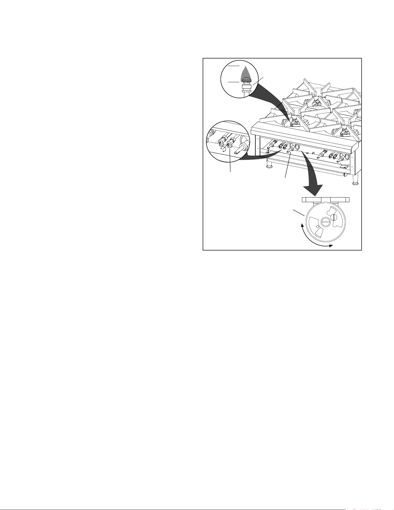
LIGHTING INSTRUCTIONS
The appliance is equipped with standing pilots; each pilot is located in front of the burner on Models GHP-2S, GHP-4S,
GHP-6S. Pilots should be lighted immediately after the gas is turned on by the manual shuto valve.
1. Turn control knobs to "OFF" position.
2. Light pilot with a lighted taper.
3 The pilot valves are located on the manifold installed
at the front of the unit behind the front panel. For
access to the valves
4. Loosen the set screws securing the knobs in position,
and remove the knobs. Remove the front panel, which
is attached to the frame with 4 sheet metal screws.
5. Turn the adjustment screws on the front of the pilot
valves. The pilots should be adjusted to blue short
ame (1/4" high) to have good ignition to the burners.
Repeat for remaining pilots.
6. If the pilot(s) is out turn o gas, wait 5 minutes and
repeat steps (1) through (5).
ADJUSTING BURNERS
7. With control valve for the front burner turned to full
"ON" position, close the air shutters to give a soft blue
ame having luminous tips and open to a point where
the yellow tips disappear, then tighten the locking
screws. Repeat this procedure with the remaining
burners.
8. Install the front panel to the front of the frame &
reconnect and secure the knobs back into position.
ADJUSTING UNIT FOR USE ON PROPANE GAS
Units are shipped with orices and pressure regulator for operation with natural gas (6" water column). To convert unit
from natural to propane gas follow these instructions
1. Set regulator outlet pressure to 10" water column. A 1/8" pipe plug on the manifold can be removed for attaching
a pressure gauge. Remove the slotted cover from the pressure regulator and invert the plug. Replace the cover
on the regulator and plug on the manifold. Regulator is now set at 10" W.C.
2. Remove natural gas orifices, #46 for all models, and install propane orifices, painted black,
(#54 for all models except) located in a bag on the outside of the front panel. In order to remove natural gas orices:
a. Remove grates and burners.
b. Remove orices from the manual valves and from ttings on extended gas pipes, replace with the propane
orices.
c. Install burners and grates.
OPERATING PROCEDURE
Each burner will deliver up to 22,000 BTU/HR of heat on all models and is controlled by a manual On/O valve. The
right control knob controls the front burner and the left control knob controls the rear burner on all models. After the
pilot is once lit and adjusted, the burners will ignite automatically by turning the control knob to any position between
On and O.
CLEANING THE EXTERIOR (Stainless Steel Only)
The exterior surface can be kept clean and attractive by regularly wiping it with a clean soft cloth. Any discoloration
can be removed with a non-abrasive cleaner. The burner grates and trough tray can be removed for cleaning.
MAINTENANCE AND REPAIRS
Contact the factory or one of its representatives or a local service company for service or maintenance if required.
1/4”
Flame
Pilot Valve
Air Shutter
Control
Valve
Pilot
IL2426
6
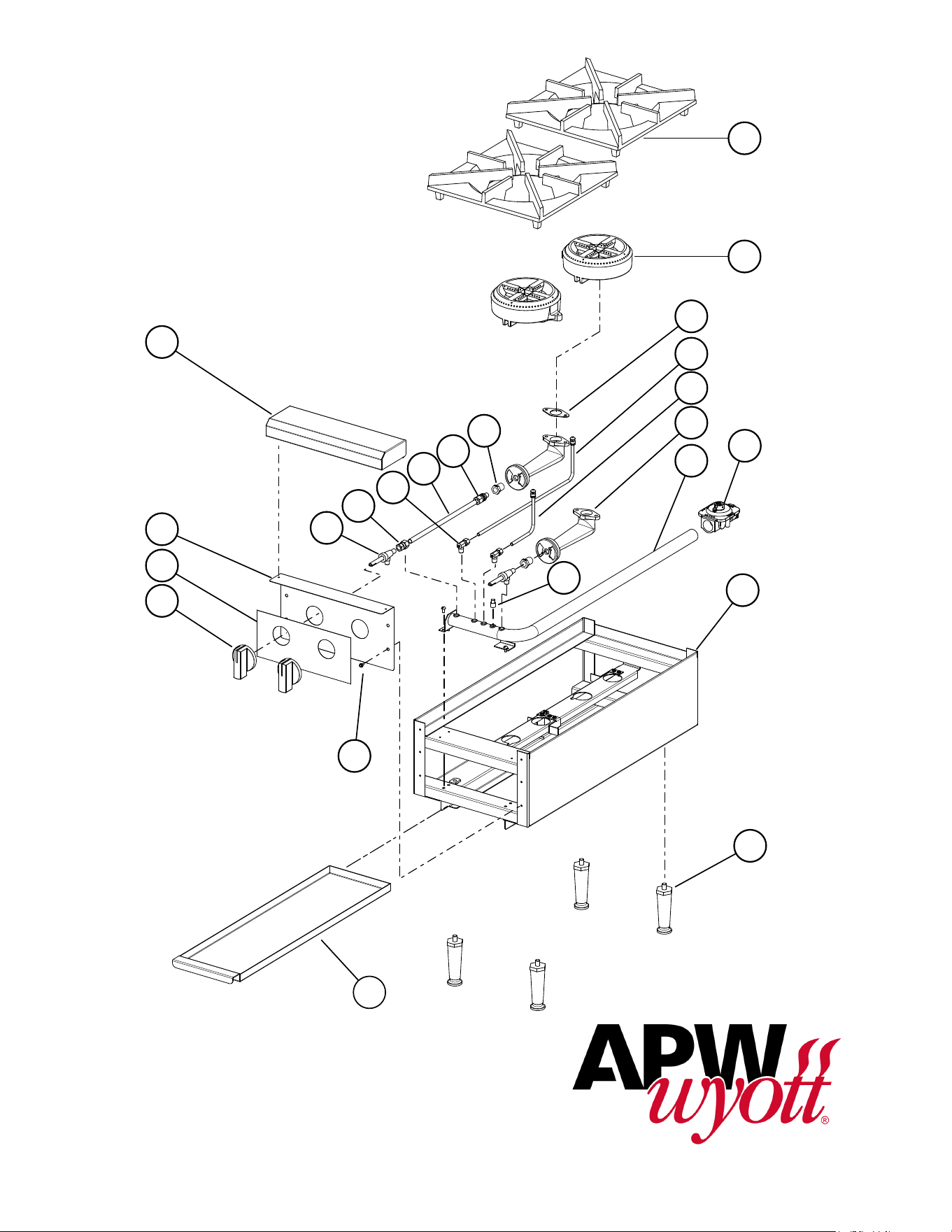
MODEL: GHP-2S, GHP-4S, GHP-6S
Gas Hotplates
SK2969 REV - 12/7/2020
1
2
3
4
5
6
8
9
10
11
14
15
16
23
17
18
19
20
21
22
12
13
7
7
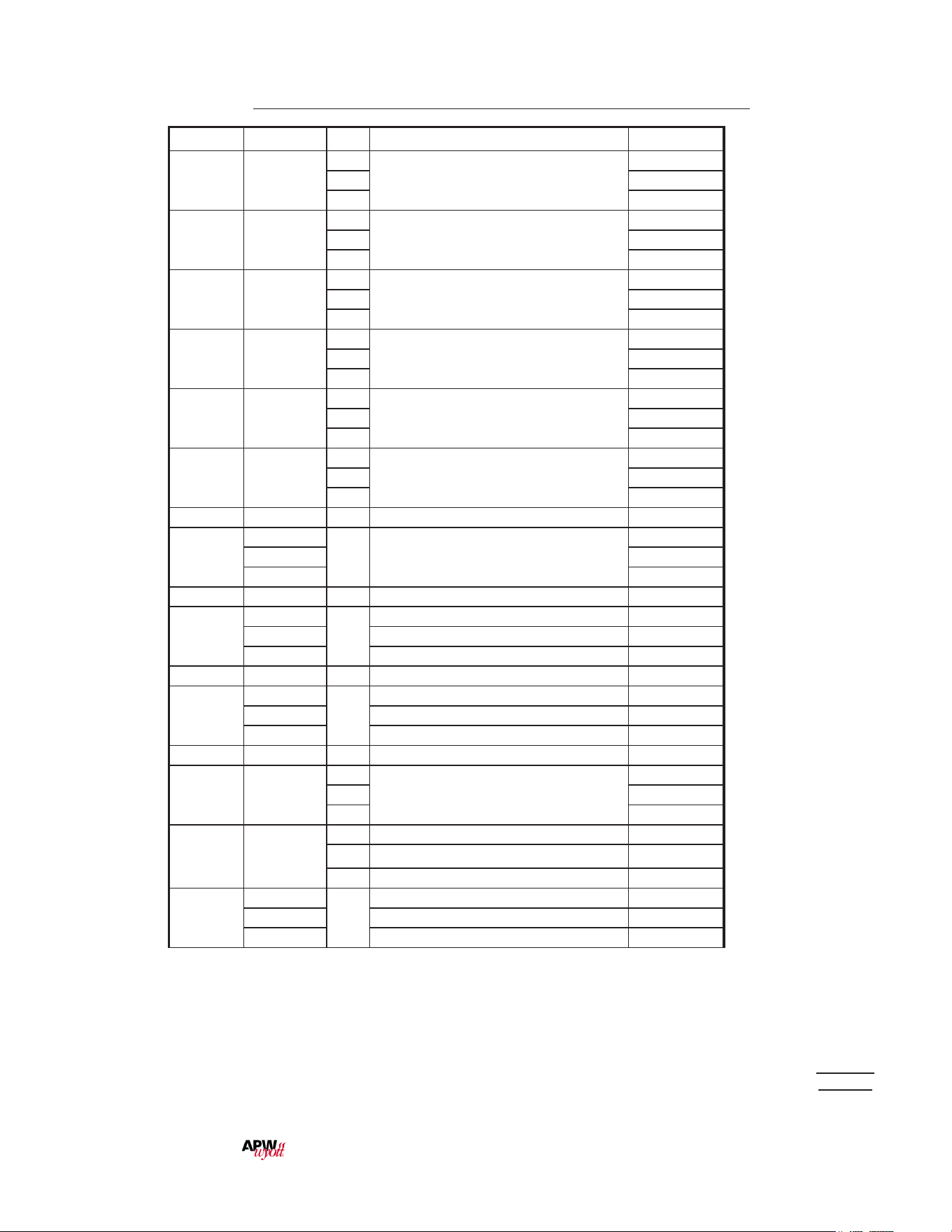
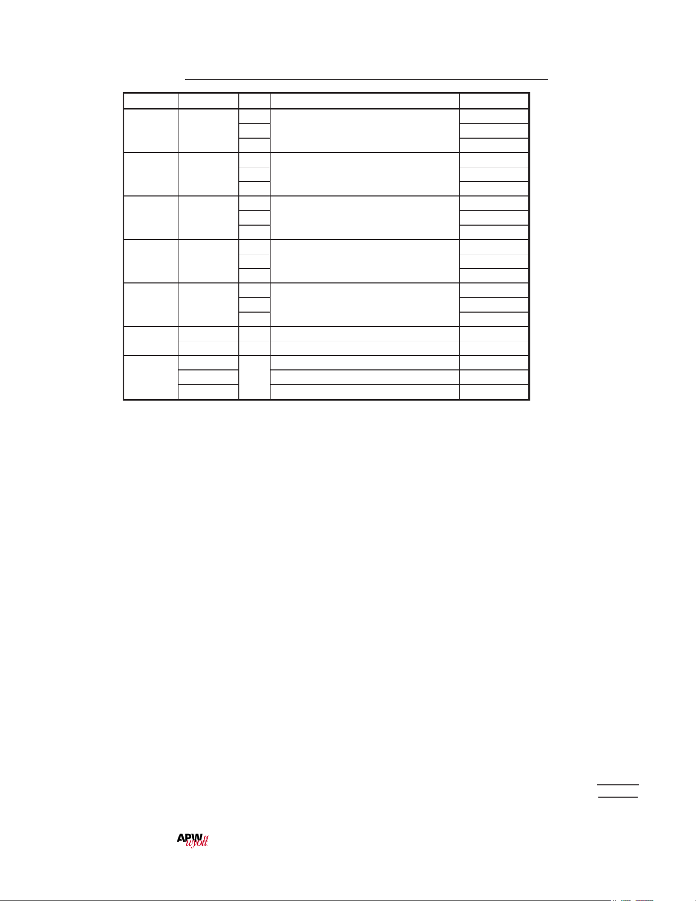
PARTS LIST December 7, 2020 Rev -
MODEL: GHP-2S, GHP-4S, GHP-6S, Gas Hotplates
Some items are included for illustrative purposes only and in certain instances may not be available.
IMPORTANT: WHEN ORDERING, SPECIFY VOLTAGE OR TYPE GAS DESIRED PAGE 1
INCLUDE MODEL AND SERIAL NUMBER OF 2
FIG No. Part No Qty Description Application
1 2F-Z16681
2
GRATE, HOTPLATE
GHP-S2
4 GHP-S4
6 GHP-S6
2 2F-Z0615
2
BURNER 7” ROUND
GHP-S2
4 GHP-S4
6 GHP-S6
3 2I-Z0752
2
GASKET-BURNER
GHP-S2
4 GHP-S4
6 GHP-S6
4 I4-602014
1
PILOT TUBE ASSY LONG
GHP-S2
2 GHP-S4
3 GHP-S6
5 I4-602013
1
PILOT TUBE ASSY SHORT
GHP-S2
2 GHP-S4
3 GHP-S6
6 2F-Z0747
2
VENTURI SHORT CASTING
GHP-S2
4 GHP-S4
6 GHP-S6
7 2P-1453 1 PLUG-PIPE 1/8NPT SQ HD ALL
8
2J-602012
1 MANIFOLD ASSEMBLY
GHP-S2
2J-604002 GHP-S4
2J-606002 GHP-S6
9 2J-Z0792 1 REGULATOR ALL
10
I4-HP0023
1
BODY ASSEMBLY GHP-S2
I4-HP0031 BODY ASSEMBLY GHP-S4
I4-HP0036 BODY ASSEMBLY GHP-S6
11 2A-Z5942 4 FOOT, 4 IN DIE CAST GHP-S2
12
I4-Z6024
1
PAN-12 GHP-S2
I4-Z6025 PAN-24 GHP-S4
I4-Z6026 PAN-36 GHP-S6
13 2C-8833 AR SCREW 8-18X1/2 HEX STL NP GHP-S2
14 2R-8706320
2
KNOB, MANUAL GAS
GHP-S2
4 GHP-S4
6 GHP-S6
15 2M-Z15449
2 GRAPHIC PANEL, 12” HTPLT GHP-S2
4 GRAPHIC PANEL, 24” HTPLT GHP-S4
6 GRAPHIC PANEL, 36” HTPLT GHP-S6
16
I4-Z15485
1
FRONT PANEL-12 GHP-S2
I4-Z15492 FRONT PANEL-24 GHP-S4
I4-Z15493 FRONT PANEL-36 GHP-S6
is a registerd trademark of APW Wyott®, A Middleby Company. All rights reserved.
8
PARTS LIST December 7, 2020 Rev -
Some items are included for illustrative purposes only and in certain instances may not be available.
IMPORTANT: WHEN ORDERING, SPECIFY VOLTAGE OR TYPE GAS DESIRED PAGE 2
INCLUDE MODEL AND SERIAL NUMBER OF 2
MODEL: GHP-2S, GHP-4S, GHP-6S, Gas Hotplates
Fig No. Part No Qty Description Application
17 2V-Y8832
2
VALVE-MANUAL GAS
GHP-S2
4 GHP-S4
6 GHP-S6
18 2A-Z0790
1
FITTING-STRAIGHT
GHP-S2
2 GHP-S4
3 GHP-S6
19 2V-6671
2
VALVE-LINCOLN BRASS#3817
GHP-S2
4 GHP-S4
6 GHP-S6
20 2V-Z0869
1
TUBE 3/8 DIA
GHP-S2
2 GHP-S4
3 GHP-S6
21 2A-Y3961
1
ORIFICE FITTING
GHP-S2
2 GHP-S4
3 GHP-S6
22
2A-Y3297 2,4,6 ORIFICE #46 NAT ALL
2A-Z1455 2,4,6 ORIFICE #54 LP ALL
23
I4-HP0019
1
FRONT BULLNOSE ASSY 12” GHP-S2
I4-HP0020 FRONT BULLNOSE ASSY 24” GHP-S4
I4-HP0021 FRONT BULLNOSE ASSY 36” GHP-S6
is a registerd trademark of APW Wyott®, A Middleby Company. All rights reserved.

9
LIMITED EQUIPMENT WARRANTY
APW warrants to the original purchaser of new APW's products to be
free from defects in material or workmanship, under normal and proper
use and maintenance service as specified by APW and upon proper
installation and start-up in accordance with the instructions
supplied with each APW unit. APWs’ obligation under this warranty is
limited to a period of one [1] year from the date of original installation, or
eighteen [18] months from original invoice date, whichever occurs first.
Defects that occur as a result of normal use, within the time period and
limitations defined in this warranty, will at APWs’ discretion have the parts
replaced or repaired by APW or a APWs-authorized service agency.
THIS WARRANTY IS SUBJECT TO ALL LISTED CONDITIONS
Repairs performed under this warranty are to be performed by an
APW authorized service agency. APW will not be responsible for
charges incurred or service performed by non-authorized repair
agencies. In all cases, the nearest APW-authorized service agency must be
used. APW will be responsible for normal labor charges incurred in
the repair or replacement of a warrantied product within 50 miles
(80.5 km) of an authorized service agency. Time and expense charges
for anything beyond that distance will be the responsibility of the owner.
All labor will need to be performed during regular service hours. Any
overtime premium will be charged to the owner. For all shipments
outside the U.S.A. and Canada, please see the International Warranty
for specific details. It is t
he responsibility of the owner to inspect
and report any shipping damage claims, hidden or otherwise, promptly
following delivery. No mileage or travel charges will be honored on any
equipment that is deemed portable. In general, equipment with a cord
and plug weighing less than 50 lb. (22.7 kg) is considered portable and
should be taken or shipped to the closest authorized service agency,
transportation prepaid.
CONTACT
Should you require any assistance regarding the operation or maintenance
of any APW Manufacturing; phone or email our service department. In all
correspondence provide the model number and serial number of the unit
needing service; include the voltage or gas type.
Normal Business Hours: 8:00 a.m. to 4:30 p.m. Central
Telephone: 800-264-7827 Tech Service Option 2
Email: [email protected]
www.apwwyott.com
WARRANTY EXCLUSIONS
THE FOLLOWING WILL NOT BE COVERED UNDER WARRANTY.
APWs’ sole obligation under this warranty is limited to either repair
or replacement parts, subject to the additional limitations
detailed below. This warranty neither assumes nor authorizes any
person to assume obligations other than those expressly
covered by this warranty.
• Any product which has not been used, maintained, or installed in
accordance with the directions published in the appropriate
installation sheet and/or owner’s manual, including incorrect gas or
electrical connection. APW is not liable for any unit which has been
mishandled, abused, misapplied, subjected to harsh chemicals,
modified by unauthorized personnel, damaged by flood, fire, or other
acts of nature [or God], or which have an altered or missing serial
number.
• Installation, labor, and job checkouts, ca
libration of heat controls,
air and gas burner/bypass/pilot adjustments, gas or electrical system
checks, voltage and phase conversions, cleaning of equipment, or
seasoning of griddle surface.
• Replacement of fuses or resetting of circuit breakers, safety
controls, or reset buttons.
• Replacement of broken or damaged glass components, quartz
heating elements, and light bulbs.
• Labor charges for all removable and consumable parts in gas
charbroilers and hotplates, including but not limited to burners,
grates, and radiants.
• Any labor charges incurred by delays, waiting time, or operating
restrictions that hinder a service technician’s ability to perform
service.
• Replacement of parts that fail or are damaged due to normal wear
or labor for replacement of parts that can be replaced during a daily
cleaning routine, such as but not limited to silicone belts, PTFE non-
stick sheets, control labels, knobs, bulbs, fuses, quartz heating
elements, baskets, racks, and grease drawers.
• Any economic loss of business or profits.
• Non-OEM parts. Use of non-OEM parts without APWs’ approval
will void the warranty.
• Units exceeding one [1] year from original installation date, or more
than eighteen [18] months from original invoice date, whichever
comes first.
ADDITIONAL WARRANTIES
• Specific/chain-specific equipment may have additional and/or
extended warranties.
The foregoing warranty is in lieu of any and all other warran�es
expressed or implied and cons�tutes the en�re warranty.

10
INSTRUCTIONS POUR L’ALLUMAGE
L’appareil est équipé de veilleuses d’allumage qui brûlent en permanence . Ces veilleuses sont situées
devant chaque brûleur sur les Modèles GHP-2S, GHP-4S, GHP-6S. Les veilleuses devraient être allumées
dès que le gaz est ouvert au moyen du robinet d’arrêt manuel.
1. Placez les boutons en position “OFF”.
2. Allumez les veilleuses à l’aide d’un briquet.
3. Les robinets des veilleuses sont situés sur le conduit installé à l’avant de l’unité, derrière le
panneau frontal. Pour accéder aux robinets, retirez le panneau frontal en dévissant les quatre (4)
vis le retenant au cadre. Tournez les vis de réglage situées à l’avant des robinets des veilleuses.
Les veilleuses devront être réglées de façon à ce que la amme soit bleue et courte (un quart de
pouce de haut) pour obtenir un bon allumage les brûleurs.
4. Si une ou des veilleuses sont éteintes, fermez le gaz, attendez 5 minutes et reprenez les étapes
(1) à (3).
5. Installez le panneau frontal sur l’avant du cadre.
RÉGLAGE DES BRÛLEURS
Retirez le panneau frontal an de pouvoir accéder aux obturateurs d’air principaux. Lorsque le robinet
de contrôle du brûleur frontal est en position “ON”, fermez les obturateurs d’air an d’obtenir une amme
bleue dont les extrémités sont lumineuses et de façon à ce que la amme ne soit pas jaune. Serrez
ensuite les vis de serrage. Reprenez cette procédure pour le brûleur arrière.
RÉGLAGE DE L’UNITÉ POUR L’UTILISATION AU PROPANE
Les unités sont envoyées avec les couvercles d’orices et le régulateur pour une utilisation au gaz naturel
(à 152 mm de colonne d’eau - 6 pouces). Pour convertir l’unité au propane, suivez les instructions ci-
dessous:
1. Réglez la pression de sortie du régulateur à 254 mm de colonne d’eau (10 pouces). Un tuyau
de 1/8 de pouce sur le conduit peut être retiré pour y connecter une jauge de pression. Retirez
le couvercle rainuré du régulateur de pression et insérez-y la prise. Replacez le couvercle sur le
régulateur et branchez sur le conduit. Le régulateur est maintenant réglé à .254 mm de colonne
d’eau (10 pouces).
2. Retirer orices de gaz naturel, # 46 pour tous les modèles, et d'installer orices propane, peinte
en noir, (# 54 pour tous les modèles excepté), situé dans un sac à l'extérieur de la face avant. An
de supprimer les orices de gaz naturel:
a. Retirez les grilles et les brûleurs.
b. Retirez les orices des robinets manuels et des raccords sur les tuyaux à gaz et remplacez-les
avec les orices à propane.
c. Réinstallez les brûleurs et les grilles.
PROCÉDURE DE FONCTIONNEMENT
Chaque brûleur se livrer à 22,000 BTU / HR de la chaleur sur tous les modèles et est contrôlé par un
manuel On / O valve. Le bouton de commande de droite commande le brûleur avant et le bouton de
contrôle de gauche contrôle le brûleur arrière sur tous les modèles. Après que le pilote est une fois allumé
et réglé, les brûleurs seront automatiquement s'enammer en tournant la molette de commande vers
n'importe quelle position entre On et O.
NETTOYAGE DE L’EXTÉRIEUR (Acier inoxydable seulement)
La surface externe peut être nettoyée en utilisant un linge propre et doux. Les décolorations peuvent
être nettoyées à l’aide d’un agent nettoyant non abrasif. Les grilles des brûleurs et l’égouttoir peuvent
être retirés pour être nettoyés.
MAINTENANCE ET RÉPARATIONS
Contactez l’usine ou l’un de ses représentants, ou bien encore une société de services locale pour la
maintenance et les réparations nécessaires.
5

11
CANALISATIONS DE GAZ
Les canalisations de gaz devraient être neuves, propres, de taille adéquate et être installées de façon
à fournir une alimentation en gaz susante pour l’appareil. Si l’appareil doit être connecté à des canalisations
déjà existantes, elles devraient être vériées pour déterminer si leur capacité est adéquate. La pâte
lubriante ne devrait être utilisée qu’avec parcimonie et seulement sur le letage extérieur des tuyaux.
Les pâtes utilisées devraient être résistantes à l’action des gaz basse pression. AVERTISSEMENT :
Toutes les saletés ou particules de métal dans les canalisations de gaz de l’appareil endommageront le
robinet automatique et aecteront son fonctionnement. Lorsque vous installez cet appareil, ainsi que les
tuyaux et raccords, assurez-vous qu’ils sont exempts de toute saleté à l’intérieur.
DÉGAGEMENT
Minimum distances aux mur pour les côtés et le dos des modèles contenus en ce manuel seront comme
suit:
Mur Mur
Combustible Non-Combustible
Plaques Chauantes 9" 0"
RÉGULATEUR DE PRESSION
Un régulateur de pression convertible réglé à 152 mm de colonne d’eau (6 pouces) pour être utilisé avec
du gaz naturel est fourni avec l’appareil. (Pour le LP modèle le régulateur est placé pour 10" pression de
eau colonne.) Reliez le régulateur au tuyau d’alimentation situé à l’arrière de l’unité et assurez-vous que
la èche du ux de gaz sur le régulateur pointe vers le conduit de distribution. L’alimentation de gaz doit
ensuite être connectée au régulateur. Un robinet de 1/8 de pouce est installé sur le conduit de distribution
pour vérier la pression. Il est possible d’accéder au conduit de distribution en retirant le panneau frontal.
ROBINET D’ARRÊT MANUEL
Un robinet d’arrêt manuel devrait être installé en amont de l’unité, à environ 183 cm (6 pieds) de l’appareil.
Ce robinet n’est pas fourni.
CONNEXION DE LA CANALISATION D’ALIMENTATION DE GAZ
L’entrée de gaz pour cet appareil est scellée à l’usine pour éviter que des saletés ne pénètrent dans l’unité.
Gardez la protection en place jusqu’à ce que vous soyez prêt à eectuer la connexion à la canalisation
d’alimentation de gaz.
RECHERCHE DE FUITES DE GAZ
Il est possible d’utiliser une solution à base d’eau et de savon ou tout autre matériau acceptable pour
localiser les fuites de gaz. Des allumettes, des bougies ou autres sources d’ignition ne devraient en
aucun cas être utilisées dans ce but.
ALIMENTATION D’AIR
Vous devrez prévoir une alimentation en air adéquate.
OUVERTURES EN DESSOUS DE L’UNITÉ
Assurez-vous que les ouvertures situées en dessous de l’unité ne sont pas obstruées. Elles
sont primordiales pour une combustion adéquate et un bon fonctionnement de l’appareil.
HOTTE ASPIRANTE
Il est primordial que des installations soient prévues pour l’évacuation des gaz et fumées.
ENTRÉE DE GAZ DES CUISINIÈRES À GAZ À PLAQUE OUVERTE
Pour le gaz naturel: La pression de sortie du régulateur est à 152 mm de colonne d’eau (6 pouces).
Pour le propane: La pression de sortie du régulateur est à 254 mm de colonne d’eau (10 pouces).
Remarque : L’appareil est équipé de couvercles d’orices pour le gaz naturel. Un autre ensemble de
couvercles est fourni pour utiliser l’appareil avec du propane. Les couvercles pour le propane sont situés
sur le panneau frontal. Les usine réglés modèles de LP n'incluent pas les capots de gaz naturel.
4
12
DONNÉES GÉNÉRALES D’INSTALLATION
MISE EN GARDE
Cet équipement est conçu et vendu pour une utilisation commerciale seulement, et pour être utilisé par
un personnel formé et expérimenté à son fonctionnement. Cet équipement n’est pas vendu pour être
utilisé à la maison ou par le public général dans les lieux de restauration. Pour tout équipement pouvant
être utilisé par le public général, prière de contacter l’usine.
Cet appareil à gaz est équipé pour les types de gaz indiqués sur la plaque signalétique à l’avant de
l’appareil. Il est envoyé réglé pour une utilisation au gaz naturel.
L’installation de l’appareil devrait être conforme au CODE NATIONAL DU GAZ COMBUSTIBLE “ANSI
Z223.1 - DERNIÈRE ÉDITION”, AINSI QU’À TOUTES LES RÈGLES ET RÉGLEMENTATIONS DE LA
COMPAGNIE DE GAZ LOCALE.
L’INSTALLATION AU CANADA DEVRAIT ÊTRE CONFORME AU CODE D’INSTALLATION AU GAZ
NATUREL ACTUEL CAN/CGA-B149.1 OU AU CODE D’INSTALLATION AU PROPANE CAN/CGA-B149.2,
AINSI QU’AUX CODES LOCAUX, LE CAS ÉCHÉANT.
AVERTISSEMENT: L'installation, le réglage, la modication, la réparation ou l'entretien
incorrect de cet appareil peut causer des dommages matérials, des blessures ou la mort.
Lire attentivement les instructions d'installation, de fonctionnement et d'entretien avant
de procéder à son installation ou entretien.
ESURE DE SÉCURITÉ
NE PAS ENTREPOSER NI UTILISER DE’ESSENCE NI AUTRES VAPEURS OU LIQUIDES
INFLAMMABLES À PROXIMTÉ DE CET APPAREIL OU DE TOUT AUTRE APPAREIL.
TENIR TOUT COMBUSTIBLE
HORS DU VOISINAGE DE L’APPAREIL.
Cet appareil, le régulateur de pression et le robinet d’arrêt individuel doivent être déconnectés du système
d’alimentation de gaz pendant les essais de pression du système lorsque les pressions d’essai sont
supérieures à 0.5 PSIG. Cet appareil et le régulateur de pression doivent être coupés de l’alimentation
de gaz en fermant le robinet d’arrêt manuel pendant les essais de pression du système d’alimentation
de gaz lorsque les pressions d’essai sont égales ou inférieures à 0.5 PSIG. Pour votre protection, nous
recommandons qu’une agence spécialisée installe votre appareil. Le personnel de cette agence devrait
connaître les installations à gaz ainsi que les exigences locales concernant le gaz. Dans tous les cas de
gure, la compagnie locale de gaz devrait venir approuver l’installation nale. De plus, des instructions
détaillées indiquant la marche à suivre dans le cas où l’opérateur détecterait une odeur de gaz devraient
être achées bien en vue à proximité de l’unité. Vous pouvez obtenir ces ins-tructions auprès de votre
fournisseur local de gaz.
MISE À NIVEAU DE L’APPAREIL
Les unités sont envoyées avec les pieds détachés. Pour installer les pieds, retirez les grilles, couchez
l’appareil sur le côté et vissez les pieds dans les logements situés sous l’appareil. Mettez l’unité à
niveau en réglant les quatre (4) pieds qui doivent être réglés à 4.45 cm (1.75 pouce) pour que l’unité soit
parfaitement alignée et de niveau avec les autres unités séries Star-Max. W
MISE EN GARDE
NE PAS RETIRER LES PIEDS.
3
13
2
2
Ces symboles sont utilisés pour souligner à l’utilisateur les
instructions d’utilisation ou d’entretien importantes contenues
dans le manuel qui accompagne l’appareil.
CONSERVEZ CE MANUEL POUR RÉFÉRENCE FUTURE
AVIS
L’utilisation de toute pièce autre que les pièces d’origine STAR dégage le fabricant
de toute responsabilité.
APW Wyott se réserve le droit de changer les spéci cations et la conception
du produit sans préavis. Ces changements ne donnent pas le droit à
l’acheteur d’obtenir les changements, améliorations, ajouts ou remplacements
correspondants pour l’équipement acheté préalablement.
Dû aux modi cations périodiques de dessins, méthodes, procédures, règles
et régulations, les spéci cations contenues dans ce manuel sont susceptibles
de changer sans préavis. Quoique APW Wyott exerce la bonne foi de fournir
le renseignement correct, APW Wyott n’est pas responsable pour les erreurs
ou les omissions dans le renseignement pourvu ou les conclusions tirées à la
suite de l’utilisation des spéci cations. En utilisant le renseignement pourvu,
l’utilisateur assume tous les risques en relation avec telle utilisation.
ENTRETIEN ET RÉPARATIONS
Contactez votre détaillent local pour les réparations ou l’entretien requis. Assurez-vous d’avoir le numéro de
modèle, le numéro de série, le voltage et la date d’achat pour un service plus rapide. Entrez l’information requise
ci-dessous pour référence rapide.
SYMBOLE DE SÉCURITÉ
N° de modèle
N° de série
Voltage
Date d’achat
Agent de service autorisé
Voir la liste pourvue avec l’appareil
Ou
Pour une liste mise à jour voir :
Site web : www.apwwyott.com
Courriel : T[email protected]
14
PLAQUES CHAUFFANTES
AU GAZ
Modèles
GHP-2S, GHP-4S, GHP-6S
Instructions
d’installation
et d’opération
2M-Z23813 Rev. - 12-7-2020
1
1
2
2
3
3
4
4
5
5
6
6
7
7
8
8
A A
B B
C C
D D
SHEET 1 OF 1
DRAWN
CHECKED
QA
MFG
APPROVED
bnabors
12/7/2020
DWG NO
TITLE
SIZE
D
SCALE
REV
.75
est une marque de Registerd APW Wyott®, la Compagnie A Middleby. Tous droits réservés.