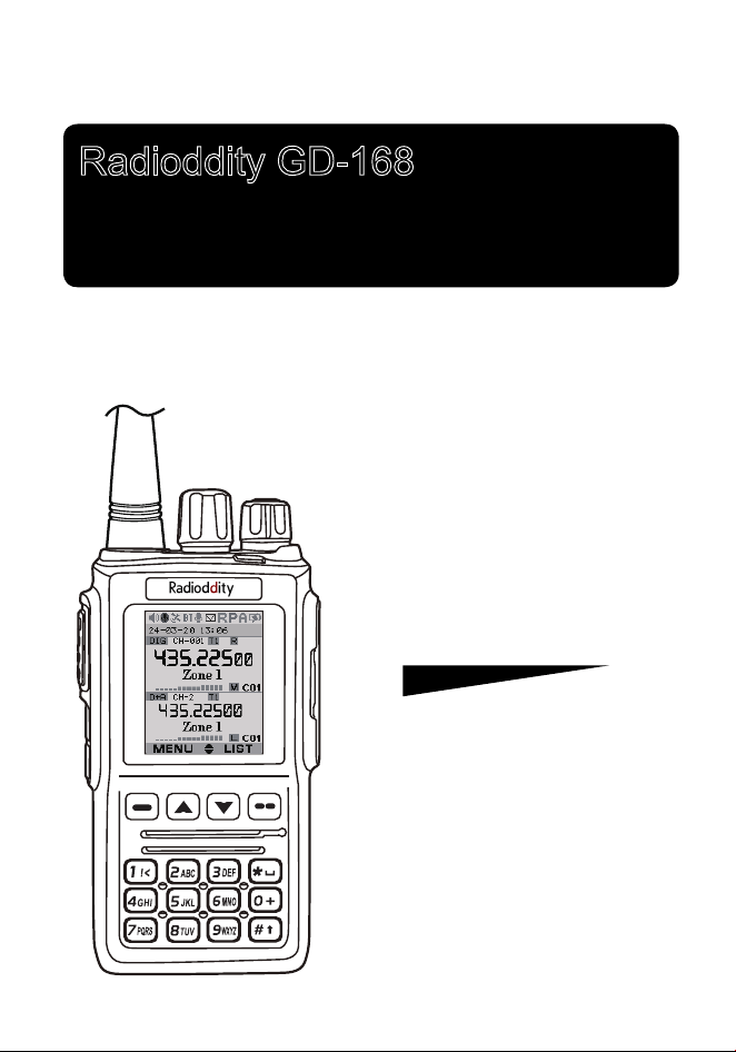
Radioddity GD-168
Digital DMR and Analog
Operating Manual
UHF/VHF Amateur Radio Transceiver
DMR
DIGITAL MOBILE RADIO ASSOCIATION

»
When you use CPS (computer program software) to program the
radio, start by reading the factory software data, and then rewrite
this data with your frequency etc., to a new saved code plug, otherwise
errors may occur.
»
The CPS allows you to program the frequency, channel type, power
etc. your programming must comply with your FCC (or other country)
OLFHQVHFHUWL¿FDWLRQ

CONTENTS
1.UNPACKING AND CHECKING THE EQUIPMENT ........................ 1
1.1 Supplied Accessories ................................................................. 1
1.2 Standard Accessories ................................................................ 2
2.BATTERY INFORMATION .............................................................. 3
2.1 Charging the Battery Pack ......................................................... 3
2.2 Charger Supplied ....................................................................... 3
2.3 Use Caution with the Li-ion Battery ............................................ 3
2.4 How to Charge ........................................................................... 4
2.5 How to Store the Battery ............................................................ 5
3. PREPARATION .............................................................................. 6
3.1 Installing / Removing the Battery ............................................... 6
3.2 Installing / Removing the Antenna ............................................. 6
3.3 Installing / Removing the Belt Clip ............................................. 7
3.4 Installing the Additional Speaker/Microphone (Optional) ........... 7
4. Radio Overview............................................................................. 8
4.1 LCD ............................................................................................ 9
4.2 Status Indications ....................................................................... 9
4.3 Programmed Key ..................................................................... 10
4.4 Hot Key Setting for PF1, PF2 ................................................... 12
4.5 Combination Key Function ....................................................... 12
5.BASIC OPERATIONS ................................................................... 13
5.1 Power on the Radio ................................................................. 13
5.2 Adjust Volume .......................................................................... 13
5.3 Main band/Sub band switch ..................................................... 13
5.4 VFO/Channel switch ................................................................ 13
5.5 Set up VFO frequency ............................................................. 13
5.6 Select a Channel ...................................................................... 13
5.7 New channel ............................................................................ 14
5.8 Delete Channel ........................................................................ 14
5.9 Receiving and Responding to a Radio Call ............................. 14

5.10 Making a Call ......................................................................... 15
5.11 Monitor ................................................................................... 15
5.12 Emergency Alarm ................................................................... 15
5.13 Battery Voltage Test ............................................................... 15
6. ADVANCED FEATURES ............................................................. 16
6.1 Access Advanced Features for Private Call ............................. 16
6.2 Set up Advanced Features for Private Call .............................. 16
7.MAIN MENU FUNCTIONS ............................................................ 18
7.1 Talk Group ................................................................................ 18
7.2 SMS ......................................................................................... 18
7.3 Call Log .................................................................................... 18
7.4 Zone ......................................................................................... 18
7.5 Scan ......................................................................................... 19
7.6 Roaming ................................................................................... 20
7.7 Settings .................................................................................... 21
7.7.1 Radio Set ................................................................................... 21
7.7.2 Chan Set.................................................................................... 27
7.7.3 Device Info................................................................................. 33
7.8 Record ..................................................................................... 33
7.9 GPS Positioning Function(optional with installed GPS) ........... 34
7.10 Satellite .................................................................................. 35
7.11 APRS Location Reporting(optional, supported by GPS) ........ 35
7.12 Digital Monitor ........................................................................ 37
8.RESET........................................................................................... 38
9.TROUBLE SHOOTING GUIDE ..................................................... 39
10.PROGRAMMING GUIDE ............................................................ 40
11.ON-LINE SERVICE AND SUPPORT .......................................... 42
SAFETY ........................................................................................... 43
12.
TECHNICAL SPECIFICATIONS ................................................. 45
1
1. UNPACKING AND CHECKING THE EQUIPMENT
Unpack the radio carefully. We recommend that you identify the items listed
in the following table before discarding the packing materials. If any items are
missing or have been damaged during shipment, please contact the carrier or
the dealers immediately.
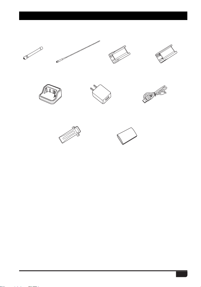
1.1 Supplied Accessories
*UFN 2VBOUJUZ
Antenna 2
Li-ion Battery Pack 2
Battery Charger 1
AC Adaptor 1
TYPE C Cable
1
Belt Clip 1
Instruction Manual 1
2
1. UNPACKING AND CHECKING THE EQUIPMENT
Digital DMR and Analog UHF/VHF Two Way Radio
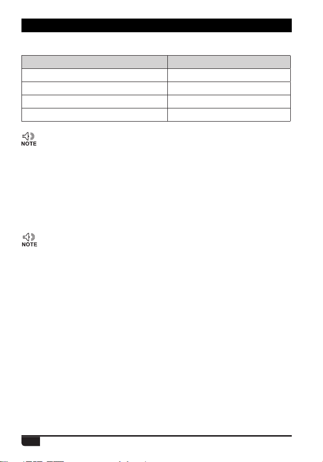
1.2 Standard Accessories
Instruction Manual
/PUF
'PSGSFRVFODZCBOEPGBOUFOOBQMFBTFSFGFSUPMBCFMJOEJDBUFEJO
UIFCPUUPNPGUIFBOUFOOB
12cm Antenna
TX-0311
38cm Antenna
TX-0313
Li-ion Battery Pack
QB-56HL(2500mAh)
AC Adaptor
NA01
Charger
QBC-56L
(5V/2A)
TYPE C Cable
QT-0046
Belt Clip
WWZZ-0029
(Program and Charge)
Li-ion Battery Pack
QB-56L(1800mAh)

3
attempt to remove the casing from the battery pack, as Radioddity cannot
be
held responsible for any accident caused by modifying the battery.
b.
The ambient temperature should be between 5
ņ
-40
ņ
Digital DMR and Analog UHF/VHF Two Way Radio
Û)Û)ZKLOH
charging the battery. Charging outside this range may not fully charge the
battery.
c.
Please turn off the radio before inserting it into the charger. It may otherwise
interfere with correct charging.
d.
To avoid interfering with the charging cycle, please do not cut off the power
or remove the battery during charging until the green light is on.
e.
Do not recharge the battery pack if it is fully charged. This may shorten the
life of the battery pack or damage the battery pack.
f.
Do not charge the battery or the radio if it is damp. Dry it before charging to
2.1 Charging the Battery Pack
The Li-ion battery pack is not charged at the factory; please charge it before use.
&KDUJLQJWKHEDWWHU\SDFNIRUWKH¿UVWWLPHDIWHUSXUFKDVHRUH[WHQGHGVWRUDJH
(more than 2 months) may not bring the battery pack to its normal maximum
operating capacity. Best operation will require fully charging/discharging the
battery two or three times before the operating capacity will reach its best
performance. The battery pack life may be depleted when its operating time
decreases even though it has been fully and correctly charged. If this is the
case, replace the battery pack.
2.2 Charger Supplied
Please use the specified charger provided by Radioddity. Other models
may cause explosion and personal injury. After installing the battery pack,
and if WKHUDGLRGLVSOD\VORZEDWWHU\ZLWKDUHGÀDVKLQJODPSRUYRLFHSURPSW
SOHDVHcharge the battery.
2.3 Use Caution with the Li-ion Battery
a.
Do not short the battery terminals or throw the battery into a fire. Never
avoid damage.
2. BATTERY INFORMATION
WARNING:
»
When keys, ornamental chain or other electric metals contact the battery
terminal, the battery may become damage or injure a human. If the battery
terminals are short circuited it will generate a lot of heat. Take care when
carrying and using the battery. Remember to put the battery or radio into
an insulated container. Do not put it into a metal container.
4
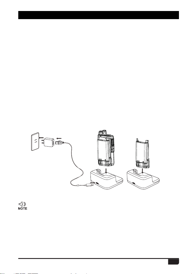
2.4 How to Charge
a.
Plug the AC adaptor into the AC outlet, and then plug the cable into the
USB-C port located on the back of the charger. The indicator lights green
and is then ready to charge a battery.
b.
Plug the battery or the radio into the charger. Make sure the battery
terminals are good in contact with charging terminals. The indicator light
turns to red--- charging begins.
c.
It takes approximately 2.5 hours for QB-56L thin battery to be fully charged,
and 3.5hours for QB-56HL thick battery to be fully charged. When the lamp
lights green, the charging is completed. Remove the battery or the radio
unit with its battery from socket
»
when charging a radio (with battery) the indicating lamp will not turn
into green to show the fully charged status if the radio is powered on.
Only when the radio is switched off will the lamp indicate normal
operation. The radio consumes energy when it is power-on, and the
charger cannot detect the correct battery voltage when the battery has
been fully charged. So the charger will charge the battery in constant
voltage mode and fail to indicate correctly when the battery has been
fully charged.
2. BATTERY INFORMATION
The radio uses a USB-C cable for charging, the USB-C cable can be inserted
into the USB-C port on radio for directly charging to the battery.
The USB-C cable can also be inserted into the USB-C port on desktop charger.
The standard 5V/2A USB-C adapter is used, it is common adapter on the market.
5
STATUS LED
Waiting(No Battery) None
Precharge Green Light
Charging Red Light
Fully Charged Green Light
»
Trouble means battery too warm, battery short-circuited or charger
short-circuited.
d
. LED Indicator:
2. BATTERY INFORMATION
»
Do not short circuit the battery terminals.
»
Never attempt to remove the casing from the battery pack.
»
Never store the battery in unsafe surroundings, as a short may cause
an explosion.
»
'RQRWSXWWKHEDWWHU\LQDKRWHQYLURQPHQWRUWKURZLWLQWRD¿UHDVLW
may cause an explosion.
2.5 How to Store the Battery
a.
If the battery needs to be stored, keep it in status of 80% discharged.
b.
It should be kept in low temperature and dry environment.
c.
Keep it away from hot places and direct sunlight.
6
Digital DMR and Analog UHF/VHF Two Way Radio
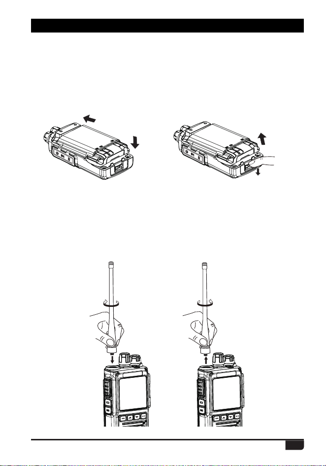
3.2 Installing / Removing the Antenna
a.
Installing the Antenna: Screw the antenna into the connector on the top of
the transceiver by holding the antenna at its base and turning it clockwise
until secure.
b.
Removing the Antenna: Turn the antenna counter-clockwise to remove it.
guides on the back of the radio and then push it.
b.
To remove the battery pack, slide the release latch at the bottom away the
3. PREPARATION
3.1 Installing / Removing the Battery
a.
battery and remove the pack from the transceiver.
Match the two top grooves of the battery pack with the corresponding
1
1
2
2
7
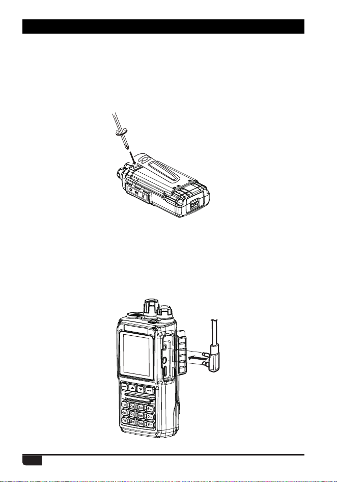
3.4
Installing the Additional Speaker/Microphone (Optional)
Pry open the rubber MIC-Headset jack cover and then insert the Speaker /
Microphone plug into the double jack.
3.3 Installing / Removing the Belt Clip
a.
Installing the Belt Clip: Place the belt clip above the corresponding holes
on the back of the radio, and screw it into place clockwise with the two
supplied screws.
b.
Removing the Belt Clip: Unscrew counter-clockwise to remove the belt clip.
3. PREPARATION
8
Digital DMR and Analog UHF/VHF Two Way Radio
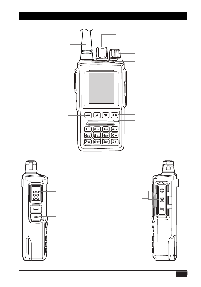
Antenna
Speaker/Mic Jacks
TYPE C
(Program and charge)
Channel Switch
POWER/VOL
LED Status Indicator
LCD
Exit Key
MIC
Menu key
Speaker
PTT Button
[PF1] Key
[PF2] Key
4. RADIO OVERVIEW
PTT
9
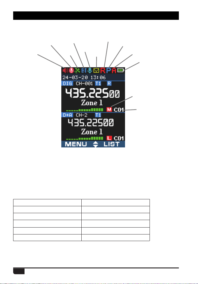
4. RADIO OVERVIEW
TX Power
Color Code
VOX
Bluetooth
Dig Monitor
Inbox
Roaming
BT PTT
Battery
Auto Power Off
Recording
GPS
4.1 LCD
The top LED will help you to identify the current radio status.
4.2 Status Indications
LED Indication Status
Flashes Red Low battery voltage
Constant Red Transmitting
Constant Green Analog Receiving
Constant Cyan Digital Receiving
Flashes Green Scan

10
4. RADIO OVERVIEW
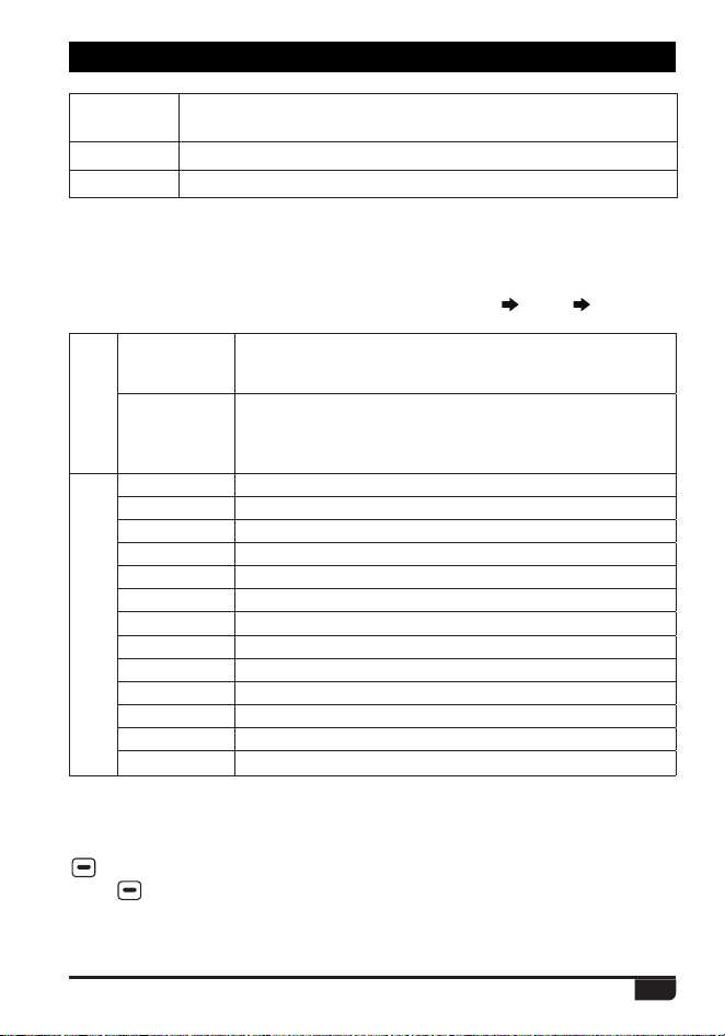
4.3 Programmed Key
It is possible to set different functions for [PF1], [PF2] keys.
Method 1: In radio Menu
Settings Radio Set Key PF1, PF2.
Method 2: In PC software
Public Optional Setting Key function.
OFF No Function
Volt Check the current battery capacity voltage
Tx Power Switch the power between super high, high, middle and low power.
TalkAround Switch between Talk Around and Repeater mode
Reverse Turn on/off the frequency reverse function.
Encryption Choose the digital encryption group for digital channel
Call
In Analog mode, send the DTMF/5TONE/2TONE encode. This
function is only valid for analog channel.
VOX Set up the VOX level
VFO / MR Switch between VFO mode and memory channel mode.
Sub PTT
Sub channel PTT, press to start the call on sub channel (NOTE: On
PF1 - PF2 Keys Only)
Scan Press the key to start or stop scanning the channels in scan list.
FM Radio FM radio on/off
Alarm Long press the key to start alarm, short press again to exit the alarm.
Record Switch Enable/disable the recording function
Record
Start/stop recording. When stop recording, the radio will remind repeat
or send the record.
SMS In digital mode, press to enter into SMS messages
Dial Start the manually dial
GPS Info
(optional)
Check the GPS position information
Monitor Monitor the weak signal or the signal with unmatched ID.
Main CH Switch
Choose channel A or channel B as the main channel
Hot Key 1~6 Selects Hot Keys 1-6 Note: Hot key setup details on next page
Work Alone Turn on/off the work alone function.
Nuisance Delete
During scanning, press the key to skip the unwanted channel
Digi Monitor In DMR mode, press the key to turn on/off digital monitor
Sub CH Hide Turn on/ off the sub channel
Prior Zone Switch to Priority Zone
VFO Scan
Press the key to start or stop the VFO scan.
The VFO scan start and end frequency should be set in CPS -Optional
Setting - VFO Scan.
MIC Sound
In digital channel, switch the microphone tone to normal or enhanced mode.

11
4. RADIO OVERVIEW
LastCall Reply
In digital channel, press the key to access the last call and press PTT
to call back.
Switch ChType
Switch the channel type(Analog, Digital, Ana+Dgi, Dgi+Ana)
Ranging
When the radio receives a call and the suspension time is on, press the
key programmed as" Ranging" to obtain the caller's position and distance.
(Both party need GPS positioned, or will receive only GPS information)
Roaming
In standby, press the key programmed as "Roaming" to search and
lock on the repeater with strongest signal. (Note: After lock on a
repeater, the radio will return to last frequency only after channel
or frequency is changed. The repeater frequency list must pre-
programmed in CPS.)
Channel
Ranging
In standby, if the call contact type for a channel is "Private call" , press
the key programmed as " Channel Ranging" to turn on this function. The
radio will automatically start ranging function when turn to this channel.
Max VOL Set
In standby, press the key programmed as "Max Volume", will enable
users to set the maximum RX volume.
Slot Set
Choose Slot for current channel, this function is only valid in repeater mode.
Aprs Type Choose Aprs Type for current channel.
Zone Select
In standby, press the programmed "Zone Select" key, it will allow you
LQSXWWKH]RQHQXPEHUDQGWKHQSUHVVFRQ¿UPNH\ZLOOVZLWFKWRWKH]RQH
Roaming Set Sets Roaming Function
APRS Set
(optional)
Sets APRS Function
Mute Timing
Press the key to mute the radio in set time. The mute timing should be
set in CPS -Optional Setting - Other -Mute Timing.
CTC/DCS Set Set the CTCSS/DCS for analog channel
TBST Send Send the TBST Tone
BT On/Off
(optional)
Enable / disable the bluetooth function
GPS On/Off
(optional)
Enable / disable the GPS function
Ch. Name
Switch between channel name display and frequency display for the
current channel
CDT Scan
Enable / disable the CTCSS/DCS scanning for the analog channel.
:KHQWKHUDGLR¿QGVPDWFKHG&7&66'&6IRUFXUUHQWFKDQQHOLWZLOO
open the speaker and start receiving.
Only the analog channels with CTCSS/DCS signalling is able to start
the CDT scanning.
ARPS Send
(optional)
Manually transmit the APRS at the current channel.
DIM Shut Light up or turn off the display/indicator.
12
4.4 Hot Key Setting for PF1, PF2
Call
Analog
6KRXOGHGLWWKHDQDORJTXLFNFDOO¿UVWWKHQFKRRVHDQDORJLQ
the hot key set. Press the key to transmit 2Tone/5Tone/DTMF
to start the analog quick call.
Digital
It allows to select a contact from the digital contact list, press
the key to switch the channel to the contact temporary. It will
switch back to the original contact after the group/personal
call hold time.
Menu
SMS Quick access to Messages in the Menu
New Msg Quick access to New Msg in the Menu - Messages
Hot Text Quick access to Quick Text in the Menu - Messages
Received SMS Quick access to Inbox in the Menu - Messages
Send SMS Quick access to Out box in the Menu - Messages
Contact list Quick access to Contact list in the Menu - Contacts
Manual dial Quick access to Manual Dial in the Menu - Contacts
Call Log Quick access to Call Log in the Menu
Dialed Calls Quick access to Dialed Calls in the Menu - Call Log
Received Calls Quick access to Answered Calls in the Menu - Call Log
Missed Calls Quick access to Missed Calls in the Menu - Call Log
Zone Quick access to Zone in the Menu
Radio set Quick access to Radio Set in the Menu - Settings
4. RADIO OVERVIEW
Enter radio Menu-Settings-Radio Set-PF1, PF2, sub menu. Users can choose
settings for Hot Keys 1-6.
Hot Key function details must be setup in PC software Public Hot key.
GPS Roam
(optional)
Enable / disable the GPS roaming function.
WX Alarm Enable / disable the weather alarm function.
SQ Level Set the squelch level.
4.5 Combination Key Function
+ number key operation:
Press
key and hold until the LCD display “Next Please Press Dial Key”,
then press the number key, it will perform the programmed function.
Combination key function shall be setup in PC software-Public-Hot key.

13
5.1 Power on the Radio
5.2 Adjust Volume
5.3 Main Band/Sub Band Switch
5.4 VFO/Channel Switch
5.5 Set Up VFO Frequency
Turn on the radio by turning the [Power/Volume] switch clockwise till a click is
heard, and the LCD displays will show a start-up message, and you will hear a
beep after 7 seconds.
Rotate the [Power/Volume] knob to adjust the volume. Turn clockwise to
increase the volume and counterclockwise to decrease the volume. The LCD
display will show the volume status during an adjustment.
Press the key programmed as Main CH Switch to switch the main channel
to the other channel if there are 2 channels shown on the display. The
channel with bold characters is the main channel.
Press the key programmed as VFO/MR to switch between VFO and
channel display.
Turn the radio to VFO mode, by the key programmed as VFO/MR, the VFO
frequency can only be set up when the channel is in the main “bold text”
channel.
Operation 1:
Input the VFO frequency directly by the keyboard.
Operation 2:
Turn the channel selector to adjust the VFO frequency steps.
5. BASIC OPERATIONS
5.6 Select a Channel
Press the key programmed as VFO/MR to switch the radio between VFO
and Channel mode, select Channel mode.
Operation 1:
Turn the channel switch to select a channel.
Operation 2:
Input the channel numbers by the keyboard. For example, if you
want switch to channel 99, input 0+0+9+9 a total of 4 digits, and it will switch
to channel 99.
A channel can either be Analog or Digital.
For the analog channels the Push-To-Talk button is always available, and
on the Digital Channels the parameters can be set up by the users / system
operators by individual channel to allow talk permit.
There are four possible settings that can be selected in the CPS channel:
(1)
Always Allow: The user can transmit all the time.
(2)
Channel Free: The radio can transmit only if the channel is free.
(3)
Different Color Code: The radio can transmit if the channel is free, but the
color code is mismatch.

14
5. BASIC OPERATIONS
5.7 New channel
5.8 Delete Channel
(1)
Press (Menu) to enter main Menu.
(2)
Select "Settings".
(3)
Select "Chan Set".
(4)
Select "New Chan".
(5)
Input the channel number by keypad, press WRFRQ¿UP
(6)
Select a zone from zone list, then Confirm To Save. The radio will start
channel saving, and saving is completed when it displays "Saved".
(7)
Now select the new channel in the radio and go to Channel Settings menu
to set up all the new channel's parameters.
(1)
In channel (MR) mode, press (Menu) to enter main Menu.
(2)
Select "Settings".
(3)
Select "Chan Set".
(4)
Select "Delete Chan" to delete current channel.
5.9 Receiving and Responding to a Radio Call
When the radio is in the digital mode, it can receive and respond to a call with
the same frequency/color code/ slot. When receiving a call:
a.
If the radio is programed with callers DMR ID number in the digital contact
OLVWZKHQUHFHLYLQJDFDOOWKHUDGLRZLOOULQJRUYLEUDWHEULHÀ\
b.
The cyan LED lights up.
c.
The bottom of LCD shows the received signal strength(RSSI), and the LCD
display will show DMR ID/name/city/state/country/call type and incoming
icon based on what is in the contact list.
d.
When the call is ended, it will display “Call end”, and you can press [PTT] to
respond to the call.
(4)
Same Color Code: The radio can transmit only if the channel is free and the
color code matches.
15
5. BASIC OPERATIONS
5.10 Making a Call
Method 1: from the Channel switch.
Turn the channel switch to choose a programmed channel.
Method 2: from the Talk Group.
(1)
Turn the channel switch to choose a programmed channel;
(2)
Press (exit) key to enter the TG List, press the / key to choose a
TG.
Method 3: from the keypad.
(1)
Turn the channel switch to choose a programmed channel.
(2)
Press (Menu) key to Talk Group, press select to enter TG.
(3)
Press / key to Manual Dial, press Select.
(4)
Input the ID number by keypad, press key to switch group ID or Private
DMR ID.
Hold the radio vertical 2.5-5cm from your mouth, press the [PTT] key to start
the call, the red LED lights up, the receiver ID/name/city/state/country/call type
and call out icon will be display on the LCD if the digital database is up-to-date
in the radio.
Release [PTT] key to receive the reply.
»
When in analog mode, if no signal, it will emit a noise when pressing
the Monitor Key.
** The Rx icon is seen when monitor is activated.
5.11 Monitor
In standby, press the key programmed as Monitor to enter Monitor. When
receiving matched carrier but the signaling / ID is unmatched or the signal
is too weak, this function allows monitor the weak signal and signal with
unmatched ID.
Press the key again to shut off speaker and return to standby.
5.12 Emergency Alarm
Press the key programmed as Alarm to turn alarm function, then press this
key again to return to normal operation.
5.13 Battery Voltage Test
Press the key programed as Voltage function to check the current battery
voltage, press this key again to return.

16
6.1 Access Advanced Features for Private Calling
6.2 Set Up Advanced Features for Private Calling
Method 1: To Access a Private Call from the Contact list
a.
Press the (Exit) key to enter the Talk Group, press the / key to a
private DMR call ID name.
b.
Press Select to View Contact, press Select to see the contact information.
c.
Press Option to access the advanced features.
6.2.1 Call Alert
Select Call Alert, it will send out a call alert, the target radio will sound a beep
or vibrate when receiving the call alert, and it will return a success call or failed
call message to the transmit radio.
6.2.2 Remote Ranging
Select Remote Ranging, and it will send out a signal for the target radio will
turn on its microphone and transmit when receiving the signaling, it will send
back the voice to the transmit radio. With this feature you can monitor the
sound activity near the target radio remotely.
6.2.3 Get GPS info
(optional)
Select Get GPS info, and it will send out a signal to the target radio which
will start the GPS positioning and send a message of its GPS position to the
transmit radio.
6.2.4 Check Radio
Select Check Radio, and it will send out a radio check to the target radio which
will send back a message if it is available or not available to the transmit radio.
With this feature, you can determine if another radio is active and powered on
in the system.
Method 2: Access from Manual Dial
a.
Press the (Menu) key to enter Talk Group, press / key to Manual
Dial.
b.
Press Select to enter Manual Dial.
c.
Input the Private DMR ID, press Option to access the advanced features.
6. ADVANCED FEATURES

17
6.2.5 Kill
Select Kill, and it will send out a kill signaling to the target radio which will be
killed (No display, no operation) when receiving the signaling and it will send
back a kill successful message to the transmit radio.
6.2.6 Wake
Select Wake, and it will send out a wake-up signaling to the killed radio and
the target radio will return to standby when it receives this signaling and send
back a Wake successful message to the transmit radio.
6.2.7 Ranging(optional)
When caller and receiver both GPS positioned, if the caller turn on ranging
function and the receiver is within communication range, transmit radio will
GHWHFWWKHGLVWDQFHDQGGLUHFWLRQEHWZHHQWZRUDGLRVDW¿[HGLQWHUYDODQGWKHQ
show the information on the display of transmit radio.
6. ADVANCED FEATURES

18
7. MAIN MENU FUNCTIONS
7.1 Talk Group
TG List:
Will display the talk group (TG) list which has been programmed in
the PC software. This list is used as a look-up table to display the contact TG
information when receiving a call.
New Contact:
Allows to create a new TG.
Manual Dial:
Input the group ID or private DMR ID to access a TG quickly.
Talker Alias: Allows Alias transmit Set / Alias receive Set.
7.2 SMS
New Msg:
Create a new message and send to a contact.
InBox:
Shows all the received messages, and allows forward or delete the
message.
OutBox:
Shows all the sent messages, and allows resend, forward or delete
of the message.
Quick Text:
Pre-saved messages, and allows to send, edit or delete the
message.
Draft:
Draft messages, and allows send, edit or deleting of the draft message.
7.3 Call Log
Last Call: The Last Call List show the last caller DMR ID and time information.
It allows you to save the last caller as a new contact if it is not in your contact.
Sent: The Sent List shows sent messages until selected and deleted.
Answered:
Shows all the answered calls, and allows deleting the call record
or saving the DMR ID as a new contact.
Missed:
Shows all the missed calls, and allows deleting a call record or
saving the DMR ID as a new contact.
7.4 Zone
7.4.1 Select a Zone
A Zone is a group of channels grouped together. GD-168 DMR radio has
250 Zones. A Zone can have the maximum of 160 analog and/or digital
channels.
Operation 1:
Press / directly to switch the zone, the LCD will display
the selected zone number or name.
Operation 2:
(1)
Press (Menu) to enter main Menu.
(2)
Select "Zone".
(3)
Select a zone from the zone list, radio will change to the selected zone.
19
7. MAIN MENU FUNCTIONS
7.5 Scan
In the PC software Public Scan list, it allows to save 250 scan lists, and
to program the required scan lists and write it into radio.
Switch the radio to channel mode, as the scan list is only valid in the channel
mode.
7.5.1 Turn On Scan
a.
Press (Menu) to enter the main Menu.
b.
Select "SCAN".
c.
Select "Scan ON/OFF".
d.
Select "ON", the radio will start scan, press any key to stop scan.
7.4.2 Add Zone
7.4.3 Delete Zone
(1)
Press (Menu) to enter main Menu.
(2)
Select "Zone".
(3)
Select "Add Zone".
1. Select "Edit name"
Input zone name by keypad, press key to delete. After edit the right
name, press
WRFRQ¿UPDQGVWRUH
2. Select "Edit Chan"
Select "Add Chan" then Select a channel from the list.
3. Select "Save": press
key to store the new zone.
(1)
Press (Menu) to enter the main Menu.
(2)
Select "Zone".
(3)
Select a Zone from the zone list.
(4)
Select Delete Zone to delete current zone.
7.5.2 Scan List Operation
a.
Press (Menu) to enter the main Menu.
b.
Select "SCAN".
c.
Select "Scan List".
d.
Select a scan list and press to enter scan list sub menu.
Select Add Scan List to enter Sub Menu
1)
Select Cur Chan, and press
to add current channel to active list.
2)
Add Channel into Scan List
Select "Add Chan", then select "channel X" to add it into scan list.

20
7.5.3 Add Scan List
a.
Press (Menu) to enter the main Menu.
b.
Select "SCAN".
c.
Select "Scan List".
d.
Select "Add Scan List"
e.
Select "Add Chan", to add wanted channels into new scan list.
f.
6HOHFW(GLW1DPHLQSXWWKHQDPHDQGFRQ¿UP
g.
Select "Store List" to save new list.
3)
Edit Scan List Name
6HOHFW(GLW1DPH,QSXWRUUHYLVHWKHQDPHDQGSUHVVFRQ¿UPWRVWRUH
4)
Store List
5)
Delete Channel from Scan List
Select "Channel X", then select "Delete CH" to remove it from scan list.
7.6 Roaming
Roaming function enable users to search the roaming channel list by a
programmed time interval and lock onto the repeater with the strongest signal.
7.6.1 Roaming On/Off
$OORZ\RXWXUQRQWKHURDPLQJPDQXDOO\$IWHUWKHURDPLQJLV¿QLVKHGLWZLOO
return to the off state. ** Manually Roaming is a onetime action only.
7.6.2 Roaming Zone
Select Roam Test Zone: select a Roaming Zone from the list to set it as active
zone. You can also scroll down the list of Zones and select Add Channel to
add a new channel to the current Roaming Zone and set the parameters
.
Select Add Channel: Add a new roaming channel to the current zone.
New Roam Ch: Allows you modify the RX frequency/TX frequency/CC/TS/CH
name for the roaming channel. Also allow you remove the roaming channel
from the zone.
Edit Name: Edit the zone name.
Select Zone: Select the roaming zone for the current channel.
Delete Zone: Delete the roaming zone from the current channel.
7.6.3 Auto Roaming Settings
Set the fixed time waiting interval to begin automatic roaming when the
repeater cannot be found, roaming will begin at the end of this time.
Fixed Time Set7KHURDPLQJZLOOEHVWDUWHGDWSUHVHW¿[HGWLPHRUVHWWRRII
.
7. MAIN MENU FUNCTIONS

21
7.6.4 Repeater Check - Off / On
Turn on this function will allow the radio to check the repeater status, the
"Repeater is out of range" icon shows if the repeater is not in range.
7.7 Settings
7.7.1 Radio Set
1.
Voice Func
(1)
Beep Tone
Beep On: The radio will beep when you press the keypad.
Beep Off: No beep when you press the keypad.
(3)
Digi Idle
Set on if you want a tone when the digital channel is free.
(4)
Ana Idle
Set on if you want a tone when the analog channel is free.
(5)
Startup Sound
Set On if you want a tone when powering on.
(6)
Talk Permit
6HOHFWLI\RXZDQWDWRQHFRQ¿UPLQJ'LJLWDODQGRU$QDORJUHSHDWHUFRQQHFWLRQ
at the start of a call.
(7)
D-Reset Tone
Select Off or On, digital call has a group call hold time and a private call hold
time to prevent the voice missing after the call. When set Digi Call Reset Tone
is On, it will beep when the hold time terminates.
(8)
Max Vol Level
Indoor: Very low volume, suitable for the indoor use.
Level 1-8: Adjustable and set up the maximum volume level.
(9)
Headset Max Vol
Indoor: Very low volume, suitable for indoor use.
Level 1-8: Set up the maximum vlomue level for earphone. When the radio
connect with earphone, it will automatically change to earphone maximum
volume.
Start Roaming:
Fixed Time: Starts timed roaming
Out of Range:
The roaming will be started when the radio cannot find a
repeater - "The repeater is out of range" icon will appear 3 times, then the radio
will perform roaming one time, and return to roaming being off automatically.
7. MAIN MENU FUNCTIONS

22
(10)
MIC Sound
It will allow you set up the microphone audio pitch.
Normal: Low pitch.
Enhance: High pitch.
(11)
SMS Prompt
Different prompt options when receiving a new message.
(12)
Call Ring
Different prompt options when receiving a new call.
(13)
DigiMic Level
Digital mic level selection.
Level 1-5: Adjustable in 5 levels, the level 1 has softest TX digital audio and
the level 5 has loudest TX digital audio.
Auto: It helps to make the TX digital audio similar, the loud audio will be
UHGXFHGDQGWKHVRIWDXGLRZLOOEHDPSOL¿HG
(14)
AnaMic Level
Analog mic level selection.
Level 1-5: Adjustable in 5 levels, the level 1 has softest TX analog audio and
the level 5 has loudest TX analog audio.
Auto: It helps to make the TX analog audio similar, the loud audio will be
UHGXFHGDQGWKHVRIWDXGLRZLOOEHDPSOL¿HG
(15)
Fix Time Mute
With the "Fix Time Mute" function activated (On) it is possible to mute the
loud speaker for special time segment.
The duration of the "Mute Time" may be set by the CPS
Optional Setting
Other Mute Timing.
(16)
TX NR
Enabling the TX noise reduction function can reduce background noise and
ambient noise in transmitted audio.
(17)
Ana RX NR
Enabling the RX noise reduction function can reduce background noise and
ambient noise in received analog audio.
(18)
RX AGC
Enable the RX AGC function, it helps to make the RX audio similar, the loud
DXGLRZLOOEHUHGXFHGDQGWKHVRIWDXGLRZLOOEHDPSOL¿HG
2.
Display Func
(1)
Back Light
LCD backlight intensity is adjustable in 5 steps
7. MAIN MENU FUNCTIONS

23
Digital DMR and Analog UHF/VHF Two Way Radio
(2)
Night Mode
With this function ON, and when the radio is in standby, it will reduce the
backlight to level 1, no matter what is the backlight brightness setting.
(3)
Light Time
Always: The backlight is always on.
5Sec-5Min adjustable.
Note:
This function is valid when turning off the power save.
(4)
Ch. Name
CH name: The radio will work in channel mode and display the channel name,
and then the programmed VFO/ MR key is not valid.
Frequency: The radio will work in VFO mode and display the frequency, which
allows the programmed VFO/MR key to switch the VFO and Memory channels.
(5)
Language
Choose the Chinese or English.
(6)
Menu Exit Time
5Sec-60Sec: When enter the menu, the radio will stay at the menu in the set
time. When the time is reached, the radio will auto exit the menu.
(7)
Start Display
Picture: The radio will display an Radioddity picture when powered on.
Character: The radio will display the characters set up in PC software when
powered on.
Customer's Pic: The radio will display the picture uploaded by PC software. In
CPS
Tool Boot Image, it will allow you to upload a Power-on Picture in
.bmp or .jpg format, the resolution of the picture shall be 128*160.
(8)
CH Background
Defualt Picture: In standby, the radio will display the default picture.
Customer's Pic: The radio will display the picture uploaded by PC software. In CPS
Tool Standby BK Picture, it will allow you upload a standby background picture.
(9)
CHG Font Color
Set the text color of the standby interface. Total of 8colors available for selection.
(10)
CH Color A
Set color for the band A channel display.
(11)
CH Color B
Set color for the band B channel display.
(12)
Zone Color A
Set color for the band A zone display.
(13)
Zone Color B
Set color for the band B zone display.
7. MAIN MENU FUNCTIONS
24
(14)
Main Ch
Channel A: The upper displayed channel will be set to become the main channel.
Channel B: The lower displayed channel will be set to become the main channel.
(15)
Sub Ch Off
Sub Channel On: Turns on the sub channel, and the radio will display both channel.
Sub Channel Off: Turns off the sub channel, and the radio will display the
main channel only.
3.
Key Func
(1)
Key Lock
Manual Lock: Long press the
key to lock the keypad. Press key, then
press the
key to unlock the keypad.
Auto Lock: Radio will auto lock the keypad when standby for a while. Press
key, then press the key to unlock the keypad.
Note:
To get the key lock function working, some options should be set ON in
CPS
Optional Setting .H\IXQFWLRQ¿UVW
Knob Lock: Set On to lock the knobs.
Keypad Lock: Set On to lock the keypad.
Side Key Lock: Set On to lock the PF1,PF2.
Forced Key Lock: Set On to prevent the key from unlocked. When this function
is ON, the keys are not able to unlock manually.
(2-11)
Key PF1, PF2
PF1 key and PF2 key are programmable, it allows you assign the key as short,
Long1 or Long2 function. Please refer to page 10&11 for the key functions.
Short: Click on the programmed key to activate the assigned function.
Long 1: Hold pressing the programmed key until the radio emits a "Du" beep,
release the key to activate the assigned function.
Long 2: Hold pressing the programmed key, do not release the key even when
the radio emits the "Du" beep, the radio will activate the assigned function.
4.
Other Func
(1)
Auto Power Off
Allow to set automatic power off when not used for a period of 10 minutes,
-120minutes
Off: Turn off the function.
(2)
TX Timer
30Sec-240Sec: The TX will be limited for the set time. When this time is
reached, the radio will auto stop transmission.
OFF: Turn off the TX time limit, and there is no limit for the transmission time.
(3)
TOT (Transmitter Out Timer) Predict
7. MAIN MENU FUNCTIONS

25
Digital DMR and Analog UHF/VHF Two Way Radio
(12)
DTMF Speed
Offers DTMF encode speed which will help the receiver decode successfully,
With the "TOT Predict" function activated (On), 5 seconds before the TOT
expiring, a beep sound is preventing that soon the transmitting mode will be
interrupted.
(4)
TxPow AGC (Automatic Level Control)
With the "TxPow AGC" function activated (On), while receiving extremely
strong signal, the TX power will automatically reduce the level of the TX Power
proportionally to the strength of the RX signal.
(5)
Freq Step
2.5K,5K,6.25K,8.33K,10K,12.5K,20K,25K,30K,50K, total of 9 frequency steps.
(6)
Ana SQ Level
Adjusts the squelch level to receive signal with different signal strength, and a
total of 5 levels offered. This function is only valid for analog channel.
(7)
Power Save
Turn on the function to extend the battery life.
Save 1:1, work 30ms, dormant 30ms.
Save 2:1, work 60ms, dormant 30ms
When turn on the power save, it may not receive the message in time.
(8)
TBST Sel
TBST frequency is used to activate some dormant repeaters, 1000Hz,
1450Hz,1750Hz, 2100Hz a total of 4 options are offered.
Press PTT and PF1 key together to transmit the TBST tone.
(9)
VOX
Enable the VOX, you can speak into the microphone to start transmitting
instead of pressing the [PTT] key. A total of 3 levels are provided.
(10)
VOX Delay
When the VOX is enabled, set up the VOX delay to help to extend the
transmission time to avoid stopping a transmission too early. 0.5sec-3sec , a
total of 26 times offered.
(11)
Scan Mod
SCM TO: When scanning and stopping for a signal, stays at the channel 5sec
before resuming the scan.
SCM CO: When scanning and stopping for signal, stays at the channel until
the signal disappears, and resumes scan 2sec later.
SCM SE: When scanning and stopping for a signal, will terminate the scan.
This function is only valid for a VFO scan.
50~500ms are the options.
7. MAIN MENU FUNCTIONS

26
7. MAIN MENU FUNCTIONS
(13)
FM Radio
Turn on or off the FM radio.
(14)
FM Radio Moni
Radio Mon On: When FM radio is used, you can still receive or transmit on the
channel.
Radio Mon Off: When FM radio is used, the radio will not permit a transmission
or reception.
(15)
Start Up Pwd
On: Set up the password for start up. You need to input the password to power
on the radio.
Off: No password is required for the radio power on start up.
The password shall be set up in CPS
Optional Setting Power on
Power on Password Char.
(16-17)
AuRepeater A or B (For VFO A or B)
Turn on the Auto Repeater function, the TX frequency in VFO mode will auto
increase or reduce frequency base on the set up offset frequency in CPS.
Off: Turn off the function.
Positive: TX frequency= RX frequency + Offset frequency.
Negative: TX frequency= RX frequency - Offset frequency.
(18)
Weather Alarm (only US version)
Turn On or Off the Weather Alarm function.
(19)
SMS Format
M-SMS: Allows SMS text communication with Motorola DMR radio.
H-SMS: Allows SMS text communication with Hytera DMR radio.
DMR Standard: Allows SMS text communication with radios set SMS in ETSI
DMR standard format.
(20)
CTC Ste (Squelch Tail Eliminate)
Tail eliminate is valid for simplex radio to radio only.
At the end of the analog call, the radio will beep 'chap' noise when detect there
is no signal, and then turn the audio off.
In order to avoid hearing the noise, you can set this function for the analog
channels with CTCSS signaling.
(21)
DCS Ste(Squelch Tail Eliminate)
Tail eliminate is valid for simplex radio to radio only.
At the end of the analog call, the radio will beep 'chap' noise when detect there
is no signal, and then turn the audio off.
In order to avoid hearing the noise, you can set this function for the analog .
(22)
No-Signal Ste

27
7. MAIN MENU FUNCTIONS
7.7.2 Chan Set
Channel set menu Route: Main Menu Settings Chan Set. The channel set
menu will change accordingly to the channel type. When the channel type is
digital, it will automatical hide the analog menus.
.
Tail eliminate is valid for simplex radio to radio only.
At the end of the analog call, the radio will beep 'chap' noise when detect there
is no signal, and then turn the audio off.
In order to avoid hearing the noise, you can set this function for the analog
channels without signaling.
(23)
Time Zone
Set up the time zone of your location.
(24)
Time Display
Set On to show the date/time on the display.
Set Off to hide the date/time on the display.
(25)
Date Time
Time Set: Allows to set up the date and time manually. Use the
/ key to
set the current year. Move to the month by pushing the [PF1] key. Set the
month, and use the [PF1] key to move forward each step. Once done, click
the Menu key to save the date and time.
GPS Check(optional): When the GPS is positioning successfully, enter this
menu, select GPS check to do the date & time correction automatically.
Format: Set the date display format to yy/mm/dd or dd/mm/yy.
(26)
TxPreamble
The radio transmits preamble before data,SMS or private call is sent. This is
useful to wake up the receiver from battery-saving mode or stop the receiver
from scanning before transimitter sending the data.
This settings allows to set the duration of the preamble tranmission.
(27)
Header RPT
Before the voice packet is transmitting, the radio will send a voice header with
*URXS&DOOLGHQWL¿FDWLRQSDFNHW¿UVW
Repeat sending voice header will help to synchronize the receiving radio and
improve the success rate of communication. This setting allows you set the
voice header repeat times.
(28)
CRC ignore
Set ON to enable the DMR CRC ignore function.
It allows the DMR vocoder selectively ignore the CRC result of Voice LC
Header, and the radio can receive more signals.

28
Č
Chan Set (Digital Channel)
(1)
New Chan
Allows to create a new channel and save the set up to the new channel.
a. Select "New ChanWKHQLQSXWQHZFKDQQHOQXPEHUDQGFRQ¿UP
E,QSXWFKDQQHOQDPHDQGFRQ¿UP
F6HOHFWD]RQHDQGFRQ¿UP7KHQHZFKDQQHOZLOOEHVDYHGWRWKHVHOHFWHG]RQH
(2)
Delete Chan
Allows to delete the current channel.
a. Select "Delete Chan",the radio will remind "Delete? "
ESUHVVFRQ¿UPDQGWKHFXUUHQWFKDQQHOZLOOEHGHOHWHG
Note: After deleting one channel, the radio will move to the next channel.
(3)
Channel Type
A-Analog : Set up to analog channel
D- Digital : Set up to digital channel
A+D TX A: Mixed analog, allow receive analog and digital signal, TX is analog.
D+A TX D: Mixed digital, allow receive analog and digital signal, TX is digital.
(4)
TX Power
Set up the TX power for current channel.
(5)
Offset
Press
/ to adjust offset frequency.
(6)
Band Width
Only narrow band 12.5KHz for digital channel.
(7)
RX Freq
Input the RX frequency by keypad, click the Menu key to save, press [Exit] key
to return.
(8)
TX Freq
Input the TX frequency by keypad, click the Menu key to save, press [Exit] key
to return.
(9)
Talk Around
When the TX radio and RX radio both are set up with Talk Around on, they can
communicate directly without a repeater. The analog channel will use the RX
frequency as TX/RX frequency, the RX CTCSS/DCS decode as TX CTCSS/
DCS encode.
(10)
Name
Allows to reset the channel name, this function is only valid in channel mode.
(11)
TX Allow
Always: Always allow transmit
7. MAIN MENU FUNCTIONS

29
Channel Free: Allow transmit when the channel is free
Different CC: Allow transmit when receive matched signal but different color code.
Same CC: Allow transmit when receive matched signal and same color code.
(12)
TX Prohibit
TX ON: Will allow transmit on the current channel.
TX OFF: Will not allow transmit on the current channel.
(13)
Radio ID
In Digital channel, it will show the DMR ID which must be programmed in the
PC software
Digital DMR ID list DMR ID. Allows edit and select an ID
for the channel, each channel allows one DMR ID.
In Analog channel, it will show the radio 5Tone self ID or DTMF self ID which
is programmed in the PC software Analog 5Tone Self ID or DTMF Self ID.
(14)
Color Code
The digital channel should have the same color code for communication as
defined by the repeater to be used; which can be programmed in the PC
VRIWZDUH&36RUGH¿QHGLQWKH0HQX
(15)
Time Slot
Set up Slot 1 or Slot 2 for the current channel.
(16)
Digi Encrypt
With the digital encryption, the communication will be confidential. A total
of 32 digital encryptions is offered, and it can be programmed in the PC
VRIWZDUH&36RUGH¿QHGLQWKH0HQX
(17)
Encrypt Type
Choose normal encryption or enhanced encryption type.
(18)
RX Group List
It will allow edit the RX Group List and assign a new RX Group List to the
channel.
Select Cur List: Select the current RX Group List.
Add Group: Add a TG to the current RX Group List.
Remove Group: Remove a TG from the current RX Group List.
(19)
Work Alone
In the PC software
Public Alarm settings Work Alone, you have to set
up the response time, warning time and response method initially.
Turn on the work alone function for the current channel. When the radios
predetermined time has been reached for the alone working time, the radio
ZLOOEHHSDVRXQGDQGVKRZ³:RUN$ORQH3UHGLFW´7KHXVHUKDVWRFRQ¿UPE\
pushing the programmed work alone key to confirm continuing work alone,
7. MAIN MENU FUNCTIONS

30
otherwise, the radio will start its alarm and send the alarm on the channel
when reaching its preset response time.
(20)
CH Ranging
In standby, if the call contact type for a channel is "Private call", The radio will
automatically start ranging function when turned to this channel. The other
radio's location will be showed on screen at intervals.
(21)
APRS Receive
Turn APRS Receive, if both radio GPS is positioned, the radio will display the
other radio's distance and position when radio is receiving.
(22)
SMS Forbid
Set On to prohibit the radio receive SMS.
(23)
DataAck Forbid
Set On to ignore the repeater data service request. The radio will not reply to
UHSHDWHUZKHQLWUHFHLYHVWKHFDOOFRQ¿UPDWLRQ606FRQ¿UPDWLRQUHTXHVWHWF
(24)
Idle TX
With "Idle TX" ON, when a repeater has one time slot occupied, the radio will
automatically switch to the other time slot for transmission. If both time slots are
occupied, the radio will beep to remind that it can not connect to the repeater.
Notice: When you use this function, make sure both the TX and RX radio
have the "Idle TX" function turned ON.
(25)
DMR Mode
Select different DMR modes for digital channel. Recommend setting is
"Repeater" for normal use.
Repeater: Allows the radios communicate through repeater or hotspot, same
slot for TX and RX.
DMO/Simplex: Only for the radio direct communicate use,without repeater
or hotspot. Allows the channel has different TX/RX frequency as long as the
other radio has the matched RX/TX frequency.
DCDM/Double Slot: Only for the radio direct communicate use,without
repeater or hotspot.The channel should have same TX/RX frequency, time slot
will be used to distinguish channels, i.e you can ceate two channels at same
TX/RX frequency but different time slot.
DCDM/TS split: Allows the radios communicate through repeater or hotspot,
different time slot for TX and RX use. The slot in channel is for RX use, TX will
use reversed slot automatically.
7. MAIN MENU FUNCTIONS

31
7. MAIN MENU FUNCTIONS
Č
Chan Set (Available in Analog Channel only)
When the channel type is analog, it will automatically hide the digital menu,
The below listed menus are for analog channel only, unlisted menus are are
the same as the digital channel, please refer to Chan Set (Digital Channel).
(4)
TCDT
Set up the CTCSS/DCS code for the TX.
(5)
RCDT
Set up the CTCSS/DCS code for the RX.
(6)
RTCDT
Set up the CTCSS/DCS code for both TX and RX
CTCSS code: 62.5Hz~254.1Hz, a total of 51 groups
DCS code: 000N~7771, a total of 1024 groups.
(7)
Optional Signal
Allows the setup of DTMF/5TONE/2TONE encode and decode for the Analog
channels.
(10)
Squelch mode
When the analog channel is set up for both CTCSS/DCS decoding and
optional signaling, you can set up the RX condition in this menu.
SQ: You can hear the call once the channel receive matched carrier.
CDT: You can hear the call when receive matched CTCSS/DCS signal.
TONE: You can hear the call when receives a matched signaling.
C&T: You can hear the call when receives a matched CTCSS/DCS and
matched signaling.
C|T: You can hear the call when receives a matched CTCSS/DCS or.
(11)
Band Width
Choose wide band or narrow band for the analog channel.
(12)
Reverse
When this function is enabled, the RX frequency, TX frequency and CTCSS/
DCS encode/decode will be reversed.
(13)
Compander
Enable this function to reduce background noise and enhance audio clarity,
especially in long range communication.
(14)
Scrambler
7KLVVSHFLDODXGLRSURFHVVFDQRIIHUDPRUHFRQ¿GHQWLDOFRPPXQLFDWLRQ
(26)
Slot Suit
Turn on Slot suit, the radio will receive calling from both slot, and will be able
to call back in the corresponding slot.

32
7. MAIN MENU FUNCTIONS
Other radios at the same frequency will receive only the distorted noises.
(19)
Busy Lock
Always: Always allows transmissions
RL: Will not allow transmit when receiving matched carrier but unmatched
CTCSS/DCS.
BU: Will not allow transmit when receiving matched carrier.
(21)
OWN ID
When the analog channel set up with 5Tone or DTMF, you can check the radio
ID number in this menu. The ID number should be set up in PC software
Analog 5Tone or DTMF self ID.
(22)
DTMF Enc
Set a DTMF ID as the default call ID for the current channel.
Press the PTT key to transmit the selected DTMF ID.
Edit the DTMF ID in Menu or with the PC programing software.
(23-24)
2Tone Enc
Set a 2Tone as the default call ID for the current channel.
Press the [PTT] key to transmit the selected 2Tone.
Edit the 2Tone in the PC programing software before it can be selected.
(25)
5Tone Enc
Set a 5Tone as the default call ID for the current channel.
Press the [PTT] key to transmit the selected 5Tone.
Edit the 5Tone in the PC programing software before it can be selected.
(26)
5Tone BOT
Set ON to send the 5Tone encode ID when press the [PTT] key.
(27)
5Tone EOT
Set ON to send the 5Tone encode ID when release the [PTT] key.
(28)
QDC1200
Set a QDC1200 as the default call ID for the current channel.
Press the [PTT] key to transmit the selected QDC1200.
Edit the QDC1200 in the PC programing software before it can be selected.
(29)
PTT ID
To get the PTT ID working, the optional signal shall be set to DTMF or 5Tone,
DQGWKH(27%27LQWKH'70)7RQHSDJHVKDOOEHVHWXS¿UVW
OFF: OFF
Start: Start, press PTT key to send a series of DTMF code or 5Tone code.
End: End, release PTT key to send a series of DTMF code or 5Tone code.
Start&End: Start and end, press and release PTT key to send a series of
DTMF code or 5Tone code.
33
7.8.2 Play the Record
a.
Press (Menu) to enter main Menu, press / key to Record.
b.
Select ListWRHQWHU5HFRUGOLVWVHOHFWD5HFRUGOLVWWRHQWHUWKH5HFRUG¿OH
c.
Select a Record to see the Detailed Information.
d.
Press Select to choose the record option.
1)
Play, it will play one record at a time, you can press
/
key to switch the
recording without return to previous menu.
2)
Loop Playback, it will play all records in a loop.
7.8.3 Send the Record
a.
Press (Menu) to enter main Menu, press / key to Record.
b.
Select Record List to enter Record list, select a Record list to enter the
5HFRUG¿OH
c.
Select a Record to see the detail information.
d.
Select Send, and it will display the Contact list or Manual Dial.
e.
Select Contact list to choose a contact, press select to send the Record.
f.
Select Manual Dial, input the DMR ID, press key to switch group ID or
private DMR ID, press select to send the Record.
7. MAIN MENU FUNCTIONS
7.8.4 Recording Manually
In the PC software, Public Optional Setting Key function, program a key
as Record.
7.8 Record
The voice record is designed for security use purpose. Each call will
EHVDYHGDVDVHSDUDWHGUHFRUGLQJ¿OH7KHVWDQGDUGYRLFHDOORZV
hours recording in DMR or analog mode.
7.8.1 Turn On/ Off the Recording
a.
Press (Menu) enter main Menu, press / key to Record.
b.
Select Record, then
6HOHFWOn/Off, select on or off to turn on or off the recording.
7.7.3 Device Info
Show the Radio ID, Radio name, serial number, model name, frequency
range, firmware version, radio data version, latest program date, picture
version, language version etc.

34
7.9.2 GPS Mode
7.9.3 GPS Roaming
Select GPS work mode for positioning use.
GPS mode is US Global Positioning System.
BDS mode is China BeiDou Navigation Satellite System.
GLONASS mode is Russia GLONASS Navigation Satellite System.
GPS Roaming function allows the radio auto switches to a zone when GPS
positioning is within the preset radiation radius of coordinates.
To get this function working, you need to set the GPS roaming page in the
&36¿UVW
7.9.1 Turn on GPS
7.9 GPS Positioning Function
(optional with installed GPS)
a.
Press (Menu) to enter the main Menu.
b.
Select "GPS".
c.
Select "GPS On".
7. MAIN MENU FUNCTIONS
»
If the GPS is not positioning, it will display “No Fixed Position”, and
the GPS icon shows a grey color. Move the radio to an open window
or outdoors, and it will take a few minutes to connect to the GPS
Satellites.
7.9.4 GPS Info
Method 1: Check GPS info from Menu
Press
(Menu) key to enter Main Menu, select "GPS", then select "GPS
Info".
Method 2: Check GPS info from programmed key
In the PC software, Public
Optional Setting Key function, program a key
as "GPS Info", then press the programmed key to check the GPS info.
a.
Press the programmed Record key, and the radio will start the recording,
and speak into the microphone.
b.
Select Record Play, and the radio will play the record.
c.
Select Record Send, and the radio will display Contact list or Manual Dial.
d.
Select Contact list to choose a contact, and press select to send the
Record.
e.
Select Manual Dial, input the DMR ID, press key to switch group ID or
private ID, press select to send the Record.

35
7.9.5 Send GPS Information
a.
When the GPS is positioning successfully, the GPS icon shows a red color.
Follow the above step to check the GPS info, press the edit key to Text edit.
b.
3UHVV&RQ¿UPDQGLWZLOOGLVSOD\6HQGRU6DYH,I\RXVHOHFW6DYHWKH*36
info will be saved as a draft message.
c.
Choose Send and it will display Contact list or Manual Dial.
d.
Select Contact list to choose a contact, press select to send the GPS info.
or
e.
Select Manual Dial, input the DMR ID, press key to switch group ID or
private ID, press
to send the GPS info.
7.11 APRS Location Reporting(
Optional, supported by GPS
)
7.11.1 Upload Type
None: No APRS.
Sel A Aprs: Select analog APRS.
Sel D Aprs: Select DMR APRS.
7.10.1 Location
GPS: The satellite function is depending on GPS location.
)L[HG7KHVDWHOOLWHIXQFWLRQLVGHSHQGLQJRQWKH¿[HGORFDWLRQEHDFRQZKLFK
\RXQHHGWRVHWXSLQ&36$356SDJH¿UVW
7.10.2 Satellite
The radio will provide a predict list for the satellites which will transit recently.
Select a satellite to check the frequency and transit time. Press PTT button to
transmit to the satellite.
7.11.2
Ana APRS
PTT Upload: Set the PTT transmit method.
Ɣ
Off: Not transmit APRS.
Ɣ
Tx Start: Transmit analog APRS when press the PTT.
Ɣ
TX End: Transmit analog APRS when release the PTT.
TX Power: Set the transmit power.
Band Width: Set the band width for transmitting.
TX frequency: Set the transmit frequency.
7. MAIN MENU FUNCTIONS
7.10 Satellite
This feature allows the radio to communicate with the satellite during
its transit.

36
7.11.3
Digi APRS
PTT Upload: Set the PTT transmit method.
Ɣ
Off: Not transmit APRS.
Ɣ
On: Transmit DMR APRS when release the PTT.
7.11.4 Digi APRS Info
The received APRS information will be saved in the radio for look back use.
Click on "Digi APRS Info" will show the received APRS information.
Click on "Delete All" will clear the information.
7.11.5
Intervals Set
This function allows you to set the analog APRS or DMR APRS auto transmit
DW¿[HGWLPHV
7.11.6 Beacon
GPS Beacon: The APRS will transmit the GPS data, only if the GPS is set to
RQ¿UVWWKHQ*36PXVWDOVRVXFFHVVIXOO\ORFNRQWKHVDWHOOLWHV
Fixed Beacon: The APRS will transmit the fixed beacon data. Someone
FDQWUDQVPLW WKH¿[HGEHDFRQZLWKRXW VHWWLQJWKH*36RQ7KH¿[HGEHDFRQ
ORFDWLRQLQIRUPDWLRQVKRXOGEHVHWLQ&36¿UVW.
Note: More setup are available by the PC software. CPS-Tools-Options-
APRS\RXKDYHWRFKHFNWKH$356ER[¿UVWWRJHW$356PHQXDGGHGWR
the left Digital menu.
(APRS is a registered trademark of Bob Bruninga, WB4APR)
7. MAIN MENU FUNCTIONS
Report Channel: Allow user to select a channel to transmit the DMR APRS,
SOHDVHVHWWKHUHSRUWFKDQQHOVLQ&36$356'LJLSDJH¿UVW
Upload Slot: Allow user to select a slot to transmit the DMR APRS
.
Ɣ
Channel Slot: It uses the slot of current channel
Ɣ
Slot 1: Use slot 1
Ɣ
Slot 2: Use slot 2
Upload ID: Allow user to set a DMR ID to receive the DMR APRS, it can be a
private ID or a group ID.
Signal Path: Set the WIDE format signal path.
TX Text6HWWKHWH[WWREHVKRZQRQWKHKWWSVDSUV¿ZHEVLWH

37
7.12.1 Response and Save a call in Digital Monitor Mode
During Digital Monitor, when receiving a call with unmatched ID, press
key, the screen will display "Monitor Response Setup Successfully", press
[PTT] key will reponse to the call.
Press
key, the radio will remind you choose a Zone, press / key to
choose a Zone, press select key to save the new channel to the Zone.
7. MAIN MENU FUNCTIONS
7.12 Digital Monitor
a.
Press (Menu) key to enter main menu, press / key to choose Digi
Moni function.
b.
Press Select to enter Digi Moni menu, press / key to choose a sub
menu.
1)
On/Off
Off: Turn off Digital Monitor
Single Slot: Monitor the current Slot
Double Slot: Monitor Slot 1 and Slot 2
2)
DigiMoni Cc
Any Cc: Monitor any color code
Same Cc: Monitor the same color code
3)
DigiMoni Id
Any Id: Monitor any TG
Same Id: Monitor the same TG
4)
Slot Hold
Off: Turn off the slot hold
On: Turn on the slot hold
Recommend to turn on slot hold when monitor double slot (Slot 1 and Slot 2),
when the signal disappears in one slot, instead of switching to the other slot at
once, the radio will hold for some seconds and wait for the audio drop.
c.
Press Select to enter the sub menu and set up.

38
a.
3RZHURIIWKHUDGLR¿UVWWRVWDUWWKHUHVHWIXQFWLRQ
b.
Then power it on while holding the [PTT] and the [PF1] button below the
PTT at the same time.
c.
The radio will start up with a note on the display – “Are you sure you
want to initialize radio?”
Press Exit to exit the reset and power on the radio.
3UHVV&RQ¿UP WRSURFHHGWKHUHVHWLW ZLOOFRPHZLWKDVFUHHQGLVSOD\
note displaying – Initialize Radio.
d.
After a re-start the radio will display the setting of time zone and the date
and the time. Use the up-down key to set the current year. Move to the
month by pushing the PF1 key. Set the month, and use the PF1 key to
PRYHIRUZDUGHDFKVWHS2QFHGRQHFOLFNWKH&RQ¿UPNH\WRVDYHWKH
date and time.
Please remember set up the time zone to avoid the date/time error.
Make sure the codeplug is saved to the PC(CPS) before you do the update
and reset. The codeplug will be eliminated and needs to be installed in the
radio.
8. RESET

39
Problems Solutions
The radio cannot be switched
on or no display after being
switched on.
A. Battery pack may not be installed
properly. Remove the battery pack
and install it again.
B. Battery power may be insufficient.
Recharge or replace the battery pack.
The battery doesn't last very
long after charging.
The battery is defective; please replace it
with a new battery pack.
Cannot talk to or hear other
members in your group.
1.Make sure the frequency and CTCSS
are the same as other members.
2.Make sure you are within range, and
not too far away from your member.
3.Make sure you are set in correct digital
mode, and frequency.
4.In digital mode, make sure to set
correct code and encrypt group is used
in current channel.
5.In digital mode, make sure to set
correct receiving contacts and receiving
group to be used.
Other voices from
non-group members are heard
on the channel.
Analog: Change the CTCSS/DCS
Tone, and make sure to change the tone
on all radios in your group.
9. TROUBLE SHOOTING GUIDE

40
10. PROGRAMMING GUIDE
Radioddity GD-168 radios ship from the manufacturer “Keypad” locked per
FCC rules.
You can press the
(Menu) key and the
(star) key to unlock the keypad
IRUWKH¿UVWWLPHRIXVH<RXZLOOQHHGWKHSURJUDPPLQJFDEOHWRFRQQHFW\RXU
radio to your computer and the CPS software for programming
.
The programming software and codeplug programming guide are available for
download from Radioddity website: www.radioddity.com
:KHQSURJUDPPLQJWKLVUDGLRIRU WKH ¿UVW WLPH LW LV UHFRPPHQGHG\RX¿UVW
5($'WKH UDGLRZLWKWKHVRIWZDUHDQGWKHQVDYH WKLV¿OHIRUIXWXUHUHIHUHQFH
as it contains the default programming and settings. In addition, after you
5($'WKLVUDGLRZLWK VRIWZDUH ¿UVW PDNH\RXUSURJUDPPLQJDQGIUHTXHQF\
FKDQJHVWKHQVHQGWKLVHGLWHG¿OHEDFNWR\RXUUDGLR
Multiple Radio ID’s
The GD-168 radio will allow multiple DMR Radio ID numbers to be used with
the radio. This feature will allow one radio to be used for example as a
Commercial Radio with its own DMR ID, and at the same time also be used as
an Amateur radio with another DMR ID.
In the PC software, Digital/ Radio ID List, you can enter your Department Unit
Number or Amateur Radio callsign.
Amateur DMR-MARC
For the best Amateur DMR experience obtain a subscriber ID from one of
many available Amateur Radio sources. A U.S. Amateur can obtain a DMR ID
From:
https://www.radioid.net/cgi-bin/trbo-database/register.cgi
For DMR repeaters in your area please see: www.repeaterbook.com
World DMR repeater network map:
https://www.repeaterbook.com/index.php/repeater-database
:RUOG'05UHSHDWHUQHWZRUNZLWKYHUL¿HG7DONJURXSVE\DFWLYLW\
https://brandmeister.network/?page=lh

41
Digital DMR and Analog UHF/VHF Two Way Radio
10. PROGRAMMING GUIDE
Worldwide Amateur Contact Database
The GD-168 DMR radios contain a separate database memory for
importing and displaying Amateur DMR individual IDs, call sign and user
name in comma-delimited format (.csv)
Please reference in the programming guide for import and export database
operations detailed.
User List Contact Database: https://ham-digital.org/status/

42
The Radioddity website provides additional information about obtaining
service or support for the Radioddity line of two-way radios and accessories.
Visit: www.radioddity.com
Warning Notes
Every effort has been made to ensure that the information in this document is
complete, accurate, and up to-date. Radioddity Radio assumes no
responsibility for the results of errors beyond its control. The manufacturer of
this equipment also cannot guarantee that changes in the equipment made by
non-authorized users will not affect the information in it.
FCC Licensing Information
This Radioddity radio operates on Commercial / Land Mobile frequencies
which require a license from the Federal Communications Commission
(FCC) for business, personal, education and recreational use. To obtain
forms, call the FCC forms hotline at: 1-800-418-3676 or go to http://www.fcc.
gov
For questions concerning commercial licensing, contact the FCC at
1-888-CALL-FCC (1-888-225-5322).
11. ON-LINE SERVICE AND SUPPORT

43
The Radioddity GD-168 DMR handheld transceiver has been carefully
designed to provide you with years of safe, reliable operation. As with
all electrical equipment, however, there are a few basic precautions you
Digital DMR and Analog UHF/VHF Two Way Radio
should take to avoid hurting yourself or damaging the radio:
5HDGWKHLQVWUXFWLRQVLQWKLVKDQGERRNFDUHIXOO\%HVXUH WRVDYHLWIRU
future reference.
5HDGDQGIROORZDOOZDUQLQJDQGLQVWUXFWLRQODEHOVRQWKHUDGLRDQGLQWKH
owner’s manual.
'RQRWFDUU\WKHWUDQVFHLYHUE\WKH DQWHQQD7KLVPD\ GDPDJHWKH
antenna or antenna terminal. Grasp the handheld by its base (not the
antenna) when you need to place or remove it.
'RQRWNHHSWKHUDGLRZLWKWKHDQWHQQDYHU\FORVHWRRUWRXFKLQJH[SRVHG
parts of the body, while transmitting. Radioddity radios will perform best,
if you speak 2-4 inches away from the microphone and the radio is vertical
. %HVXUHWKH³377´NH\LVQRWSUHVVHGZKHQ\RXGRQRWQHHGWRWUDQVPLW
'RQRWRSHUDWHWKHUDGLRQHDUXQVKLHOGHGHOHFWULFDOEODVWLQJFDSVRULQDQ
explosive atmosphere.
'RQRWWUDQVPLWZLWKRXWWKHDQWHQQDILWWHG RQWKHUDGLR7KRXJKLWLV
SURYLGHGZLWKDSURWHFWLRQLWPD\GDPDJHWKH7;RXWSXW¿QDOVWDJH
5HVSHFWWKHHQYLURQPHQWFRQGLWLRQV7KHUDGLRLVGHVLJQHGWREHXVHGLQ
heavy environments, however avoid exposing it to extremely hot or cold
temperature (out of the range between –20°C to +55°C). Do not expose
the transceiver to excessive vibrations as well as dusty or rainy locations.
1HYHUWU\WRGLVDVVHPEOHRUVHUYLFHWKHUDGLRE\\RXUVHOIDVLGHIURPWKH
routine maintenance described in this handbook). It may cause damage
to the radio transceiver and void your warranty requiring extensive repair
work. Always contact your local dealer for assistance.
8VH RQO\ DXWKRUL]HG DFFHVVRULHV 8VLQJ QRQ5DGLRGGLW\ UDGLR
EUDQGaccessories may seriously damage your handheld transceiver
and void your warranty.
'RQRWVSLOOOLTXLGRIDQ\NLQGLQWR\RXUUDGLR,IWKHWUDQVFHLYHUJHWVZHW
immediately dry it by a soft and clean cloth.
6ZLWFKWKHUDGLRRIIEHIRUH\RXFOHDQLW)ROORZWKHGLUHFWLRQVGHVFULEHGLQ
the paragraph “Care and maintenance”.
SAFETY

44
+DQGOHWKHEDWWHU\SURSHUO\1HYHUSODFHWKH/,LRQEDWWHU\LQ\RXUSRFNHW
or purse with loose coins. This could result in short circuiting the battery.
%H FHUWDLQ WKDW \RXU SRZHU VRXUFH PDWFKHV WKH UDWLQJ OLVWHG IRU WKH
supplied battery charger (AC adapter). If you are not sure, check with your
authorized Radioddity dealer.
$YRLGGDPDJLQJWKHSRZHU FDEOHRIWKHEDWWHU\FKDUJHU'RQRWVWHSRQ
or place anything on it as this could result in a damaged charger power
cord. This product complies with the requirements of the Council Directives
89/336/EEC and 73/23/EEC on the approximation of the laws of the
member states relating to electromagnetic compatibility and low voltage.
Your wireless hand-held portable transceiver contains a low power
transmitter. When the Push-to-Talk (PTT) button is pressed it sends out
radio frequency (RF) signals. The device is authorized to operate at a duty
factor not to exceed 50% TX and 50% RX.
In August 1996, the Federal Communications Commission (FCC) adopted
RF exposure guidelines with safety levels for hand-held wireless devices.
To maintain compliance with the FCC’s RF exposure guidelines, this
transmitter and its antenna must maintain a separation distance of least 2
inches from your face. Speak in a normal voice, with the antenna pointed
up and away from the face at the required separation distance. The belt
clip is for storage purposes only.
AVOID TRANSMITING ON HIGH POWER WHILE RADIO IS ATTACHED
TO YOUR BELT. To transmit, hold the device away from your body and
ensure the antenna is at least 2 inches from your body when transmitting.
WARNING
SAFETY
46
Digital DMR and Analog UHF/VHF Two Way Radio
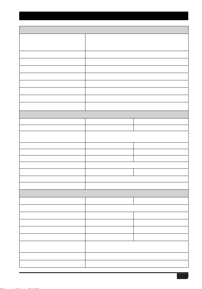
General
Frequency Range
Channel Capacity 4000 channels
Channel Spacing 25KHz (Wide Band) ,12.5KHz (Narrow Band)
Phase-locked Step 5KHz, 6.25KHz
Operating Voltage 7.4V DC ±20%
Frequency Stability ±1.5ppm
Operating Temperature -20
ć
~ +55
ć
Size 103.5×53.5×35.5mm (with battery pack)
Weight 224g (with battery pack)
Receiving Part
Wide band Narrow band
Sensitivity(12dB SINAD) ȝ9 ȝ9
0.3uV/-117.4dBm (BER 5%)
%JHJUBM4FOTJUJWJUZ
0.7uV/-110dBm (BER 1%)
Adjacent Channel Selectivity G% G%
Spurious Emission G% G%
Spurious Rejection G% G%
#MPDLJOH
84db
Hum & Noise G%
ı
40dB
Audio Distortion
Audio Power Output P:ȍ
Transmitting Part
Wide band Narrow band
Power Output
VHF: 5/2.5/1W/0.2W, UHF: 4.5/2.5/0.5W/0.2W
Modulation
±5.0KHz@25KHz ±[email protected]
Adjacent Channel Power
G% G%
Hum & Noise
G% G%
Spurious Emission
G%F 60dBc
,)[EBUBὈ,'9%
4FSK
%JHJUBM.PEVMBUJPO
,)[EBUBWPJDFὈ,'9&
Audio Distortion
&SSPSSBUF
12. TECHNICAL SPECIFICATIONS
US: 136-174MHz, 400-480MHz
European Users should note that operation of this unit in Transmit mode
requires the operator to have a valid Amateur Radio Licence from their
respective Countries Amateur Radio Licencing Authority for the Frequencies
and Transmitter Power levels that this Radio transmits on. Failure to comply
may be unlawful and liable for prosecution. At this subject, refer to the “EU”
VSHFL¿FDWLRQJXLGH(8
Products with the symbol (crossed-out wheeled bin) cannot be
disposed as household waste. Electronic and Electric Equipment
should be recycled at a facility capable of handling these items and
their waste by products.
In EU countries, please contact your local equipment supplier
representative or service center for information about the waste
collection system in your country.
Disposal of your Electronic and Electric Equipment

IMPORTANT NOTICE TO THE ENDUSERS:
The European version of these devices is intended for amateur radio use only. It
operates on the following bands:
VHF = 144-146 MHz
UHF = 430-440 MHz
The operator must have the appropriate licence. Any manipulation of the
aforementioned frequency bands is prohibited.
WICHTIGER HINWEIS FÜR DEN ENDBENUTZER:
Die europäische Version dieser Geräte ist nur für den Einsatz im Amateurfunk
vorgesehen. Es arbeitet auf den folgenden Bändern:
UKW = 144-146 MHz
UHF = 430-440 MHz
Der Betreiber muss über die entsprechende Lizenz verfügen. Jegliche Manipulation
der vorgenannten Frequenzbänder ist untersagt.
AVIS IMPORTANT AUX UTILISATEURS FINAUX:
La version européenne de ces appareils est destinée uniquement à une utilisation
dans le domaine radioamateur. Il fonctionne sur les bandes suivantes:
VHF = 144-146 MHz
UHF = 430-440 MHz
L'opérateur doit avoir la licence appropriée. Toutes les manipulations de les
bandes de fréquences précitées sont interdite.
AVVISO IMPORTANTE PER L’UTENZA FINALE:
La versione europea di questi apparati è destinata esclusivamente all'uso
radioamatoriale. Esso opera sulle seguenti bande:
VHF = 144-146 MHz
UHF = 430-440 MHz
L'operatore deve possedere la licenza appropriata. Qualsiasi manipolazione delle
suddette bande di frequenza è interdetta.
AVISO IMPORTANTE A LOS USUARIOS FINALES:
La versión europea de estosequiposestádiseñada para uso exclusivo de
UDGLRD¿FLRQDGRV2SHUDHQODVVLJXLHQWHVEDQGDV
VHF = 144-146 MHz
UHF = 430-440 MHz
El operadordebeestarprovisto de la licenciacorrespondiente. Quedaprohibidacualq
uiermanipulación de las citadas bandas de frecuencia.
EL