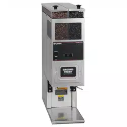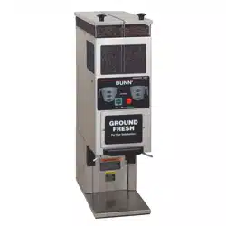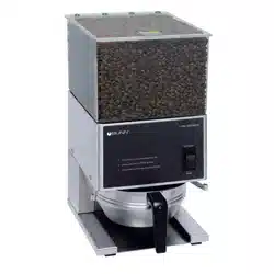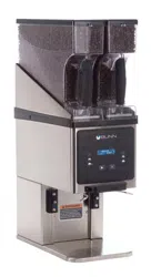
Coffee Grinder
Portion Control Grinder with 2 Hoppers
G9-2 HD, G9-2T HD, G9-2 HD-S
10218.0000 AB 11/24 © 1994 - 2024 Bunn-O-Matic Corporation
www.bunn.com
For Technical Service, contact Bunn-O-Matic Corporation at 1-800-286-6070.
INSTALLATION & OPERATING GUIDE
Bunn-O-Matic Corporation
Post Office Box 3227, Springfield, Illinois 62708-3227
Phone (217) 529-6601 | Fax (217) 529-6644

2
111224
Bunn-O-Matic Corp. (“BUNN”) warrants equipment manufactured by it as follows:
1) All coffee and tea dispensers/servers, MCR/MCP/MCA single cup brewers, and BUNNlink
®
electronic circuit and/or
control boards – 1 year parts and 1 year labor.
2) Product-specific warranties for Premia
™
,Crescendo
®
, Fast Cup
®
, Sure Immersion
®
, Sure Tamp
®
and others – 1 year
parts and 1 year labor. Please visit commercial.bunn.com/support/warranty-lookup for further details.
3) All other equipment – 2 years parts and 1 year labor plus added warranties as specified below:
a) Electronic circuit and/or control boards – parts and labor for 3 years.
b) Compressors on refrigeration equipment – 5 years parts and 1 year labor.
c) Grinding burrs on coffee grinding equipment for 4 years or 40,000 pounds of coffee, whichever comes first.
4) For customers subscribed to BUNNlink
®
, BUNN reserves the right to periodically auto-push critical software
updates that will enhance functionality or performance of the BUNN equipment, unless the customer requests
advance notice of such software updates from BUNN in writing.
These warranty periods run from the date of installation. BUNN warrants that the equipment manufactured by it will
be commercially free of defects in material and workmanship existing at the time of manufacture and appearing
within the applicable warranty period. This warranty does not apply to any equipment, component or part that was
not manufactured by BUNN or that, in BUNN’s judgment, has been affected by misuse, neglect, alteration, improper
installation or operation, improper maintenance or repair, non periodic cleaning and descaling, equipment failures
related to poor water quality, damage or casualty. In addition, the warranty does not apply to replacement of items
subject to normal wear with use including but not limited to user replaceable parts such as seals and gaskets. This
warranty is conditioned on the Buyer 1) giving BUNN prompt notice of any claim to be made under this warranty by
telephone at (217) 529-6601 or by writing to Post Office Box 3227, Springfield, Illinois 62708-3227; 2) if requested
by BUNN, shipping the defective equipment prepaid to an authorized BUNN service location; and 3) receiving prior
authorization from BUNN that the defective equipment is under warranty.
THE FOREGOING WARRANTY IS EXCLUSIVE AND IS IN LIEU OF ANY OTHER WARRANTY, WRITTEN OR
ORAL, EXPRESS OR IMPLIED, INCLUDING, BUT NOT LIMITED TO, ANY IMPLIED WARRANTY OF EITHER
MERCHANTABILITY OR FITNESS FOR A PARTICULAR PURPOSE. The agents, dealers or employees of BUNN
are not authorized to make modifications to this warranty or to make additional warranties that are binding on BUNN.
Accordingly, statements by such individuals, whether oral or written, do not constitute warranties and should not be
relied upon.
If BUNN determines in its sole discretion that the equipment does not conform to the warranty, BUNN, at its
exclusive option while the equipment is under warranty, shall either 1) provide at no charge replacement parts
and/or labor (during the applicable parts and labor warranty periods specified above) to repair the defective
components, provided that this repair is done by a BUNN Authorized Service Representative; or 2) shall replace
the equipment or refund the purchase price for the equipment.
THE BUYER’S REMEDY AGAINST BUNN FOR THE BREACH OF ANY OBLIGATION ARISING OUT OF THE
SALE OF THIS EQUIPMENT, WHETHER DERIVED FROM WARRANTY OR OTHERWISE, SHALL BE LIMITED, AT
BUNN’S SOLE OPTION AS SPECIFIED HEREIN, TO REPAIR, REPLACEMENT OR REFUND.
In no event shall BUNN be liable for any other damage or loss, including, but not limited to, lost profits, lost sales, loss
of use of equipment, claims of Buyer’s customers, cost of capital, cost of down time, cost of substitute equipment,
facilities or services, or any other special, incidental or consequential damages.
BUNN-O-MATIC COMMERCIAL PRODUCT WARRANTY
3
USER NOTICES
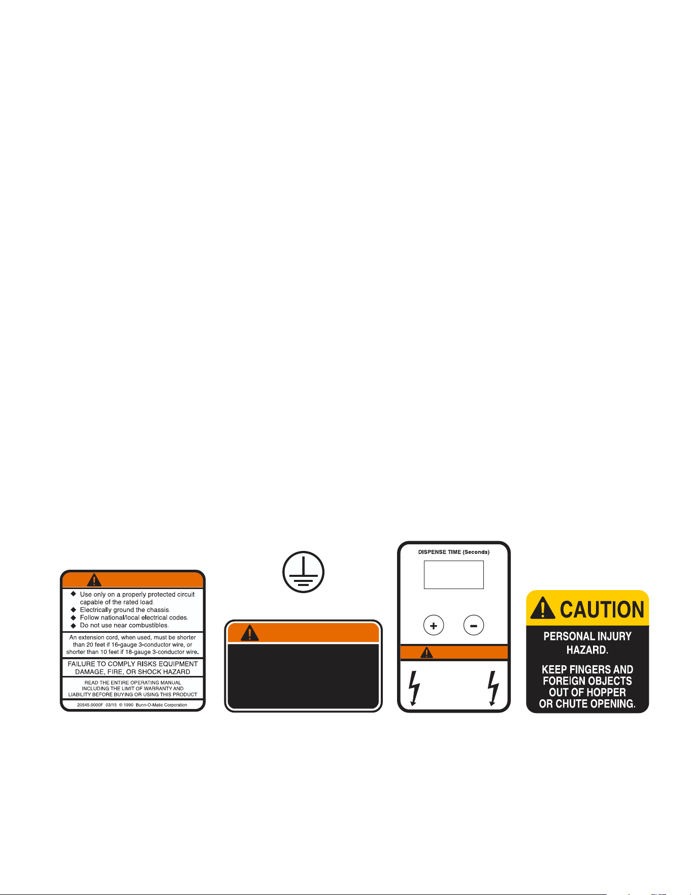
Carefully read and follow all notices on the grinder and in this manual. They were written for your protection.
All notices on the grinder are to be kept in good condition. Replace any unreadable or damaged labels.
111224
WARNING
20545.0000
05876.0000
To reduce the risk of electric shock,
do not remove or open cover.
No user-serviceable parts inside.
Authorized service personnel only.
Disconnect power before se rvicing.
WARNING
37881.0000
00824.0002
34891.0000
WARN ING
HAZARDOUS
VOLTAGE
DISCONNECT FROM
POWER SOURCE
BEFORE REMOVING!
INTRODUCTION
This equipment will store up-to six pounds of whole bean coffee in each of two hoppers and grind it to a
preset grind and amount into an awaiting funnel and filter from most commercial drip coffee brewers. The
equipment is only for indoor use on a sturdy counter or shelf. Adequate space must be available above the
grinder to raise the lids when adding beans. Use only with whole bean coffee.
The grind is preset at the factory to drip specifications as set forth by the United States Department of
Commerce and adopted by the Coffee Brewing Center of the Pan American Coffee Bureau. Adjustments
may be made to alter both the amount and grind from the factory setting.
ELECTRICAL REQUIREMENTS
This grinder has an attached cordset and requires 2-wire, grounded service rated 120 volts ac, 15 amp,
single phase, 60 Hz for 120V models and 230 volts ac, 10 amp single phase, 50 Hz for 230V models.
CONTENTS
BUNN-O-MATIC COMMERCIAL PRODUCT WARRANTY ......................................................................................2
INTRODUCTION .......................................................................................................................................................3
USER NOTICES ........................................................................................................................................................3
ELECTRICAL REQUIREMENTS ...............................................................................................................................3
NORTH AMERICAN REQUIREMENTS ....................................................................................................................4
CE REQUIREMENTS ................................................................................................................................................4
OPERATING CONTROLS .........................................................................................................................................5
INITIAL SET-UP ........................................................................................................................................................5
CLEANING ................................................................................................................................................................6
COFFEE GRINDING .................................................................................................................................................6
ADJUSTMENTS ........................................................................................................................................................7
Burr Adjustment .....................................................................................................................................................7
Timer Adjustment ...................................................................................................................................................8
WIRING SCHEMATIC ...............................................................................................................................................9

4
• This appliance must be installed in locations where it can be overseen by trained personnel.
• For proper operation, this appliance must be installed where the temperature is between 5°C to 35°C.
• Appliance shall not be tilted more than 10° for safe operation.
• An electrician must provide electrical service as specified in conformance with all local and national codes.
• This appliance must not be cleaned by water jet.
• This appliance is not intended for use by persons (including children) with reduced physical, sensory
or mental capabilities, or lack of experience and knowledge, unless they have been given instructions
concerning use of this appliance by a person responsible for its safety.
• This appliance is intended to be used for commercial applications, for example in kitchens of
restaurants, canteens, hospitals and in commercial enterprises such as bakeries, butcheries, etc., but not
for continuous mass production of food.
• Children should be supervised to ensure they do not play with the appliance.
• If the power cord is ever damaged, it must be replaced by the manufacturer or authorized service
personnel with a special cord available from the manufacturer or its authorized service personnel in
order to avoid a hazard.
• Machine must not be immersed for cleaning.
• Machine rated IX P1.
CE REQUIREMENTS
• This appliance must be installed in locations where it can be overseen by trained personnel.
• For proper operation, this appliance must be installed where the temperature is between 41°F to 90°F
(5°C to 32°C).
• For proper operation, this appliance must be installed where humidity is 50%.
• Appliance shall not be tilted more than 10° for safe operation.
• An electrician must provide electrical service as specified in conformance with all local and national codes.
• This appliance must not be cleaned by pressure washer.
• This appliance can be used by persons if they have been given supervision or instruction concerning use
of the appliance in a safe way and if they understand the hazards involved.
• Keep the appliance and its cord out of reach of children.
• Appliances can be used by persons with reduced physical, sensory or mental capabilities or lack of
experience and knowledge if they have been given supervision or instruction concerning use of the
appliance in a safe way and understand the hazards involved.
• If the power cord is ever damaged, it must be replaced by the manufacturer or authorized service
personnel with a special cord available from the manufacturer or its authorized service personnel in
order to avoid a hazard.
• Machine must not be immersed for cleaning.
• This appliance is intended for commercial use in applications such as:
– staff kitchen areas in shops, offices and other working environments
– by clients in hotel and motel lobbies and other similar types of environments
• Access to the service areas permitted by Authorized Service personnel only.
NORTH AMERICAN REQUIREMENTS
111224
5
INITIAL SET-UP
1. Open the top lid. Clear all foreign objects and shipping
material from the hopper compartment and the entrance to
the grind chamber.
2. Remove the lower front inspection panel.
3. Plug-in the grinder.
4. Select either the Left or Right hopper with the selector
switch. Do not press the Start Switch.
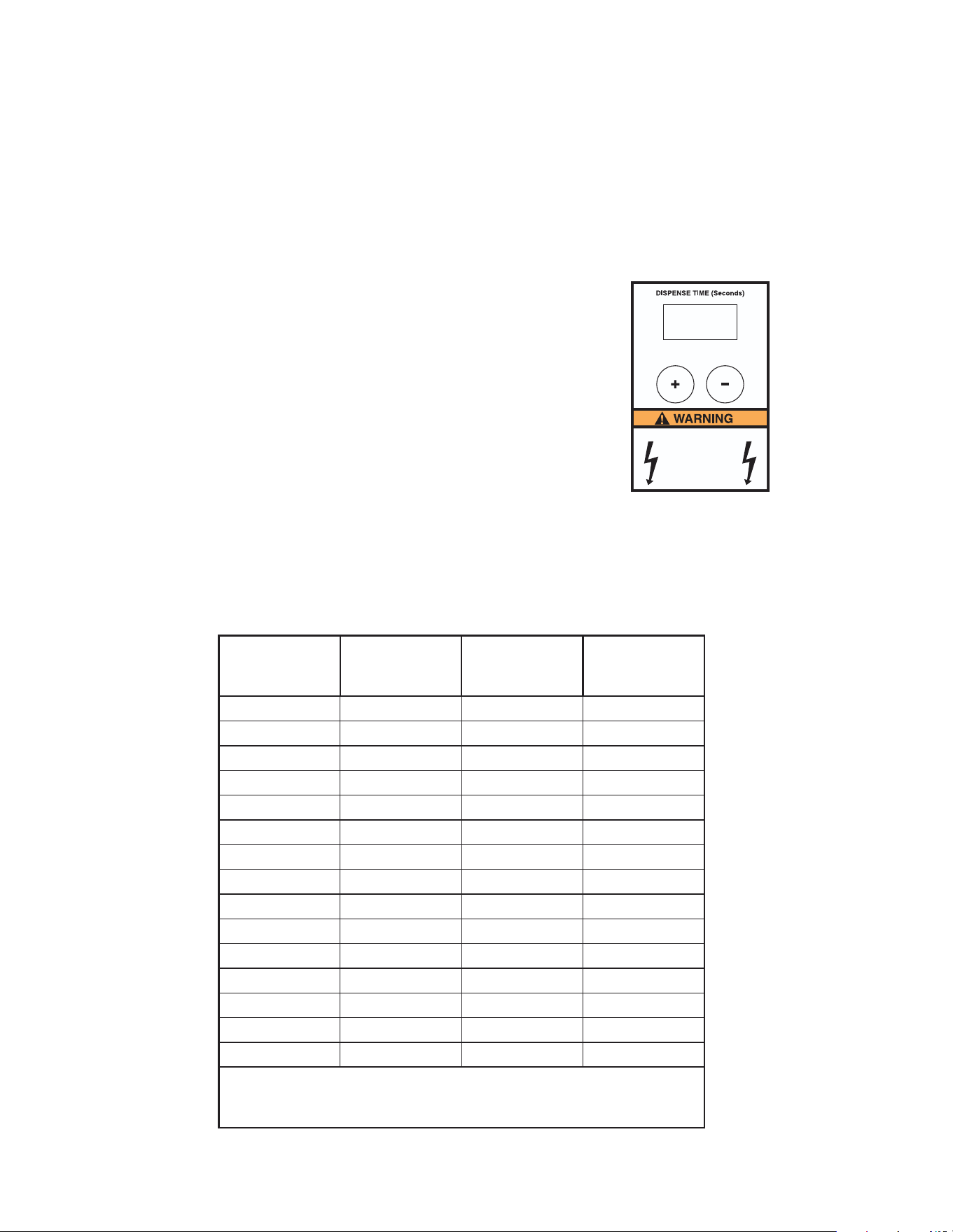
5. If grinder has an analog timer, proceed to step 6.
If grinder has a digital timer, momentarily press the center
(DISPLAY) button on the dispense timer panel.
The readout will indicate the present timer setting in
seconds and will remain displayed for five minutes.
6. Adjust the timer setting to obtain the desired amount of
coffee for the selected hopper.
7. Repeat steps 4 thru 6 for the other hopper.
8. Fill the hopper compartments with whole bean coffee.
(Capacity 6 pounds each).
The grinder is now ready for use.
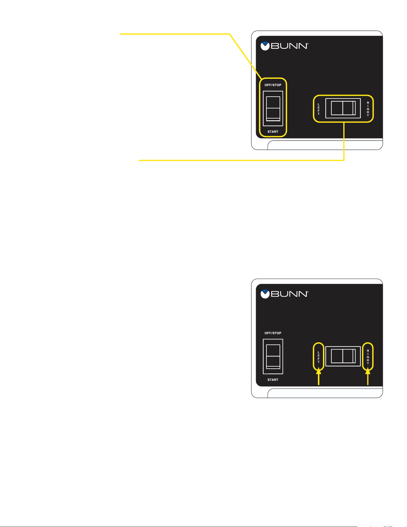
Off/On/Start Switch
OFF - (upper position) Switching to this position stops all
operation of the grinder.
ON - (middle position) The switch will return to this position
after a grind cycle has begun and will remain in this position
after grinding has ceased.
START - (lower, momentary position) Pressing the switch
initiates a timed grind cycle.
P633
111224
OPERATING CONTROLS
Hopper Selector Switch
Left - Switching to this position allows beans to be dispensed from the left hopper.
Right - Switching to this position allows beans to be dispensed from the right hopper.
Dispense Timer
The dispense timer controls the amount of beans that will leave the hopper in a grind cycle. The timer can
be adjusted to dispense a different amount from each hopper. The scale is from 0.4 to 150.0 seconds.
Refer to the Adjustments section for timer setting chart (page 8).
6
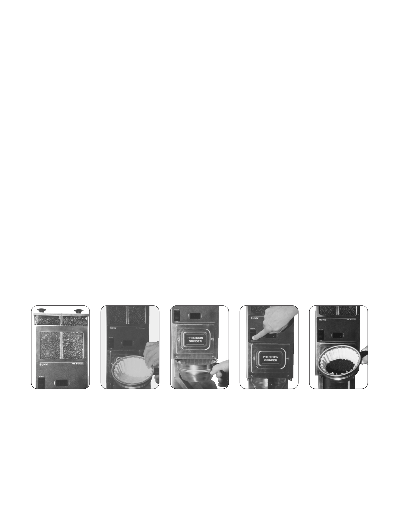
1. Visually inspect the selected hopper for an ample supply of whole bean coffee.
2. Place a paper filter into the brew funnel. The filter must not be folded-over or tilted to one side.
3. Insert the funnel into the funnel rails and push until it stops.
4. Momentarily press the start switch. The grinding action will stop automatically after the preset amount of
ground coffee is dispensed into the funnel.
5. Remove the funnel from the grinder and level the bed of grounds by gently shaking.
6. The loaded funnel is now ready for use in any commercial drip coffee brewer according to the
manufacturer’s instructions.
111224
CLEANING
6 Month Cleaning
WARNING - Unplug the grinder before the removal of any panel or grind chamber-housing parts.
1. Clean all exterior surfaces using a damp cloth rinsed in any mild, nonabrasive, liquid detergent. Care
should be taken not to scratch the grinder with any abrasive material.
2. Empty all beans from hopper(s). Plug in the grinder; place an empty funnel with filter into the funnel
rails. Press and release the “GRIND” button. Run a few cycles until all coffee in the grind chamber is
dispensed and disconnect the grinder from the power source.
3. Remove the upper front inspection panel.
4. Remove the two screws holding the front cover to the burr housing. Carefully remove the burr housing
front cover. Clean inside surface with a dry stiff non-metallic bristle brush and wipe with a dry clean cloth.
5. Carefully remove the rotor cup, shear plate burr rotor and motor shaft extension from the grinder. Clean
all parts with a dry stiff non-metallic bristle brush and wipe with a dry clean cloth.
6. Clean the grind chamber with a dry stiff non-metallic bristle brush and wipe with a dry clean cloth.
7. Reinstall the motor shaft extension, burr rotor, shear plate, rotor cup and front cover to the burr housing.
8. Reinstall the upper front inspection panel,
9. Refer to the “Adjustment” section of the Operating and Service manual for burr adjustments.
Replace the dechaffer assembly.
05995.1000 Dechaffer Plate (package of 6)
COFFEE GRINDING
P597
STEP 1
P598
STEP 2
P599
STEP 3
P600
STEP 4
P601
STEPS 5 & 6
Weekly
Clean all exterior surfaces using a damp cloth rinsed in any mild, nonabrasive, liquid detergent. Care should
be taken not to scratch the grinder with any abrasive material.
7
1
0
2
3
4
5
6
7
8
9
10
11
12
13
14
15
C
O
A
R
S
E
-
F
I
N
E
B
U
N
N
Early
Models
Late
Models
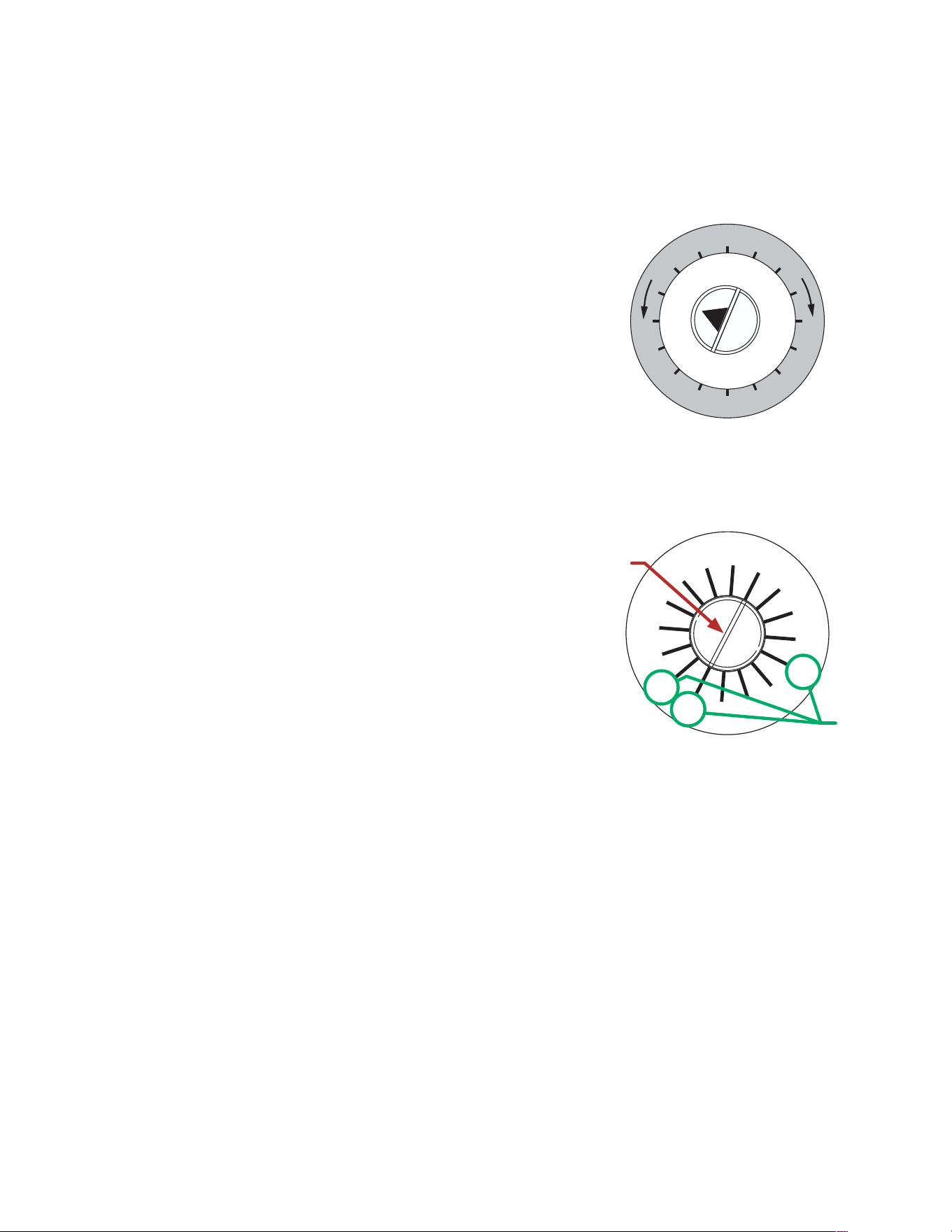
The grind can be set from very fine to very coarse. The amount may be adjusted for use in most commercial
coffee brewers. The following procedures should be used to make adjustments. A change in the burr
adjustment will also change the amount dispensed. Any adjustment of the burrs should be followed by an
adjustment of the timer.
continued >
111224
Burr Adjustment
1. Unplug the grinder and empty all beans from the hoppers.
2. Plug-in the grinder, momentarily press the off/on/start
switch to the “START” (lower) position (with either hopper
selected) and release, run a few grind cycles until all of the
coffee in the grind chamber is used-up.
3. Remove the upper front inspection panel.
4. Early Models only, loosen the burr adjustment screw from
its locked position.
5. Early Models only, hand loosen the adjustment locking nut
around the screw approximately one turn.
6. Press the off/on/start switch to the “START” (lower) position
and release, slowly turn the adjusting screw in a clockwise
direction until a metallic whine is heard due to the rubbing
of the grinding burrs. (It may be necessary to start more
than one grind cycle to obtain this sound.)
7. Early Models only, make a mark with a pen on the decal
to note the position of the arrow on the grind adjustment
screw.
Late Models, turn plastic grind indicator until screw slots
line up with “O” on the indicator.
8. The following settings approximately correspond to the
CBC recognized grinds. All are referenced from the arrow
position noted in #7.
FINE GRIND: Rotate the adjusting screw 7 hash marks in
a counterclockwise direction.
DRIP GRIND: Rotate the adjusting screw 8 hash marks in
a counterclockwise direction.
REGULAR (COARSE) GRIND: Rotate the adjusting screw
12 hash marks in a counterclockwise direction.
9. Early Models only, hold the adjusting screw in its set
position with a screwdriver while tightening the lock nut
to a snug position by hand.
Slightly loosen the adjusting screw and retighten it to
its prior position.
The lock nut should now be tight against the burr
housing front cover.
ADJUSTMENTS
Adjusting
Screw
Hash
Marks
8
APPROXIMATE TIMER SETTINGS IN SECONDS
continued from previous page
111224
Timer Adjustment
1. Unplug the grinder and remove the lower front inspection panel.
2. Determine the grind setting. (The factory setting is Drip, to determine other settings, refer to the
previous section.)
3. Use the table below to find approximate timer setting for the grind and amount of coffee desired.
4. Plug-in the grinder. Select either the right or left hopper with the selector switch.
Do not press the start switch.
5. If grinder has an analog timer, proceed to step 6.
If grinder has a digital timer, momentarily press the center
(DISPLAY) button on the dispense timer panel. The readout
will indicate the present timer setting in seconds and will
remain displayed for five minutes.
6. Adjust the timer setting to obtain the desired amount of
coffee for the selected hopper.
7. Verify the setting by weighing a few samples. Use the
following table as an approximate guide only.
8. Repeat steps 4 thru 7 for the other hopper.
HAZARDOUS
VOLTAGE
DISCONNECT FROM
POWER SOURCE
BEFORE REMOVING!
I 0.0
ADJUSTMENTS
Digital
Timer
WEIGHT
(OUNCES)
FINE
(7*)
DRIP
(8*)
REGULAR
(12*)
1.5 0.5 0.5 0.5
1.75 0.7 0.6 0.6
2.0 1.0 0.8 0.8
2.25 1.4 1.4 1.2
2.5 1.9 1.8 1.6
2.75 2.4 2.2 2.0
3.0 2.9 2.7 2.5
3.25 3.3 3.1 2.9
4.0 4.8 4.4 4.0
6.0 8.6 7.9 7.5
8.0 12.0 11.5 10.9
10.0 15.7 15.1 14.1
12.0 19.6 18.5 17.5
14.0 23.5 22.0 20.9
16.0 27.0 25.3 24.3
*Hash Mark Settings.
Refer to Burr Adjustment on previous page.
9
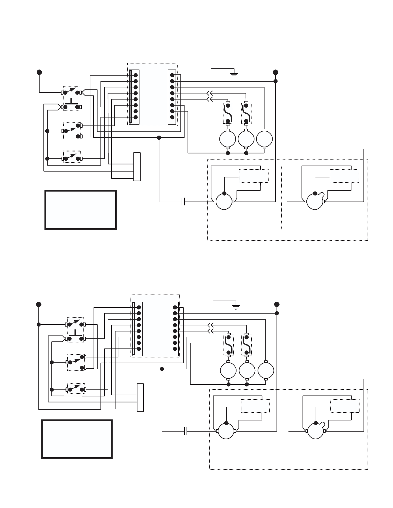
WIRING SCHEMATIC
BLU
VIO
YEL
GRY
TAN
ORA
WHI/BLK
RED/BLK
WHI/GRN
WHI/ORA
WHI/YEL
WHI/RED WHI/BLK
BLK
WHI/RED
WHI/BLU
M
K1
SOL
1
RT
SOL
2
LT
L2L1
WHI/BLU
WHI/BLK
YEL
10756.0000 L 08/30/24 ©1993 BUNN-O-MATIC CORPORATION
L1
N
K1 N.O.
SCHEMATICWIRINGDIAGRAMG9-2 HD
(DIGITAL TIMER)
OFF/ON/START
SW
HOPPER
SELECTOR SW
TAN
1
8
DIGITAL
TIMER
P1 P4
1
8
GRINDER INTERFACE
CONNECTOR
GRY
PNK
4
1
2
3
BLU
BLU
GREEN
OPTIONAL
MULTI-SET SW
BLU
PNK
BLK
GRN
RT
LT
BLK
SNUBBER
WHI/BLK
WHI/BLK
WHI/BLKWHI/BLU
M
L2L1
WHI/BLK
WHI/BLU
YEL
SNUBBER
FRANKLIN MOTOR MARATHON MOTOR
ALTERNATE MOTOR
120 VOLTS AC
2 WIRE
SINGLE PHASE
60 Hz
BLU
VIO
YEL
GRY
TAN
ORA
WHI/BLK
RED/BLK
WHI/GRN
WHI/ORA
WHI/YEL
BLK
WHI/RED
LT
10756.0001 K 08/30/24 © 1997 BUNN-O-MATIC CORPORATION
L1
N
SCHEMATICWIRINGDIAGRAMG9-2 HD
(ANALOG TIMER)
OFF/ON/START
SW
HOPPER
SELECTOR SW
TAN
1
8
ANALOG
TIMER
P1 P4
1
8
GRINDER INTERFACE
CONNECTOR
GRY
PNK
4
1
2
3
BLU
BLU
GREEN
OPTIONAL
MULTI-SET SW
BLU
PNK
BLK
GRN
RT
LT
K1
SOL
2
SOL
1
RT
WHI/BLK
WHI/BLK
WHI/RED WHI/BLKWHI/BLU
M
L2L1
WHI/BLU
WHI/BLK
YEL
K1 N.O.
SNUBBER
WHI/BLKWHI/BLU
M
L2L1
WHI/BLK
WHI/BLU
YEL
SNUBBER
FRANKLIN MOTOR MARATHON MOTOR
ALTERNATE MOTOR
120 VOLTS AC
2 WIRE
SINGLE PHASE
60 Hz
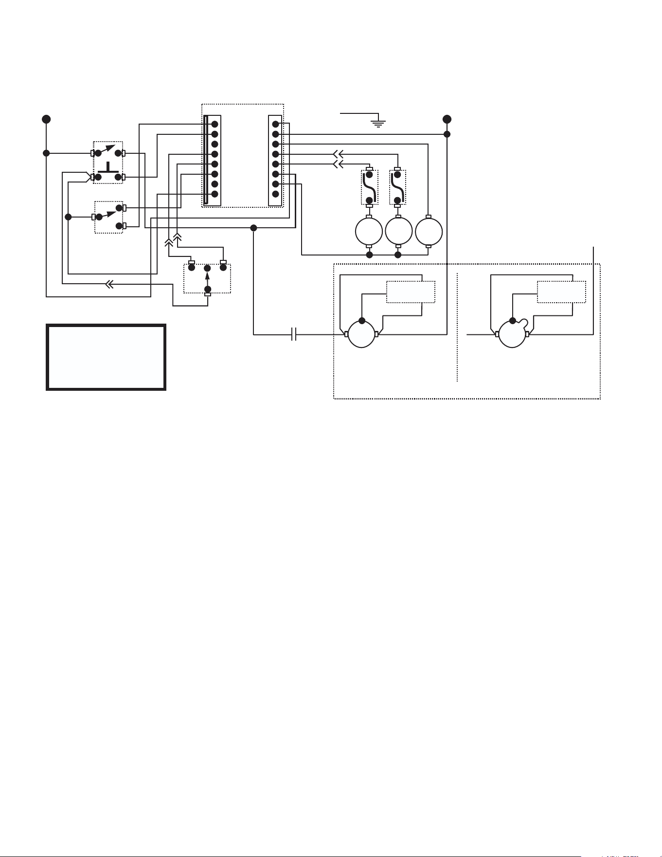
10
WIRING SCHEMATIC
BLU
VIO
YEL
GRY
TAN
ORA
WHI/BLK
RED/BLK
WHI/GRN
WHI/ORA
WHI/YEL
BLK
WHI/RED
K1
SOL
1
RT
SOL
2
LT
10756.0002 L 08/30/24 ©1998 BUNN-O-MATIC CORPORATION
L1 N
SCHEMATIC WIRING DIAGRAM G9-2 HD
(DIGITAL TIMER W/BATCH SELECTOR)
OFF/ON/START
SW
HOPPER
SELECTOR SW
TAN
1
8
DIGITAL
TIMER
P1 P4
1
8
GRY
PNK
BLU
GREEN
BLU
PNK
BLK
RT
LT
BLK
BATCH SELECTOR
SWITCH
L S
M
WHI/BLK
WHI/BLK
WHI/RED WHI/BLKWHI/BLU
M
L2L1
WHI/BLU
WHI/BLK
YEL
K1 N.O.
SNUBBER
WHI/BLKWHI/BLU
M
L2L1
WHI/BLK
WHI/BLU
YEL
SNUBBER
FRANKLIN MOTOR MARATHON MOTOR
ALTERNATE MOTOR
120 VOLTS AC
2 WIRE
SINGLE PHASE
60 Hz