98076230 - F 12/12/24
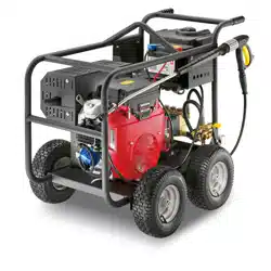
High Pressure Cleaner
Combustion engine - Cold Water
Register
your product
www.kaercher.com/welcome
English..... 3

MODELS:
1.575-152.0
HD 3.0/30 Pb
1.575-154.0
HD 3.7/35 Pb
1.575-155.0
HD 3.0/40 Pb
1.107-480.0
HD 3.5/30 Pb
3
KARCHER Surface Cleaner 9.802-898.0
CONTENTS
Model Number
Serial Number
Date of Purchase
The model and serial numbers will be found on a decal attached to
the pressure washer. You should record both serial number and date
of purchase and keep in a safe place for future reference.
Introduction & Important Safety Information ............................................... 4
Component Identication ............................................................................6
Assembly instructions .................................................................................7
Operating instructions.................................................................................8
Detergents & General Cleaning Techniques .............................................10
Shutting Down And Clean-Up .................................................................... 11
Storage ...................................................................................................... 11
Troubleshooting ......................................................................................... 12
Preventative Maintenance .........................................................................13
Oil Change Record ....................................................................................13
Exploded View - 1.575-152.0,154.0,155.0 ................................................14
Specications ............................................................................................17
Hose & Spray Gun Assembly ....................................................................19
VRT3 Unloader Exploded View And Parts List .......................................... 20
UU1 Unloader Exploded View ..................................................................21
VBT Unloader Exploded View .................................................................22
KM.3 Series Pump Exploded View ............................................................ 23
KBP3030R Series Pump Exploded View ..................................................25
Manual, Karcher • 9.807-623.0
4
INTRODUCTION & IMPORTANT SAFETY INFORMATION
Thank you for purchasing this Pressure Washer.
We reserve the right to make changes at any time
without incurring any obligation.
Owner/User Responsibility:
The owner and/or user must have an understanding
of the manufacturer’s operating instructions and
warnings before using this pressure washer.
Warning information should be emphasized and
understood. If the operator is not uent in English,
the manufacturer’s instructions and warnings shall
be read to and discussed with the operator in the
operator’s native language by the purchaser/owner,
making sure that the operator comprehends its
contents.
Owner and/or user must study and maintain for
future reference the manufacturers’ instructions.
The operator must know how to stop the machine
quickly and understand the operation of all controls.
Never permit anyone to operate the engine without
proper instructions.
SAVE THESE INSTRUCTIONS
This manual should be considered a permanent
part of the machine and should remain with it if
machine is resold.
When ordering parts, please specify model and
serial number. Use only identical replacement
parts.
This machine is to be used only by trained
operators.
IMPORTANT SAFETY
INFORMATION
WARNING
READ OPERATOR’S
MANUAL THOROUGHLY
PRIOR TO USE.
OPERATIONS
SAFETY
MAINTENANCE
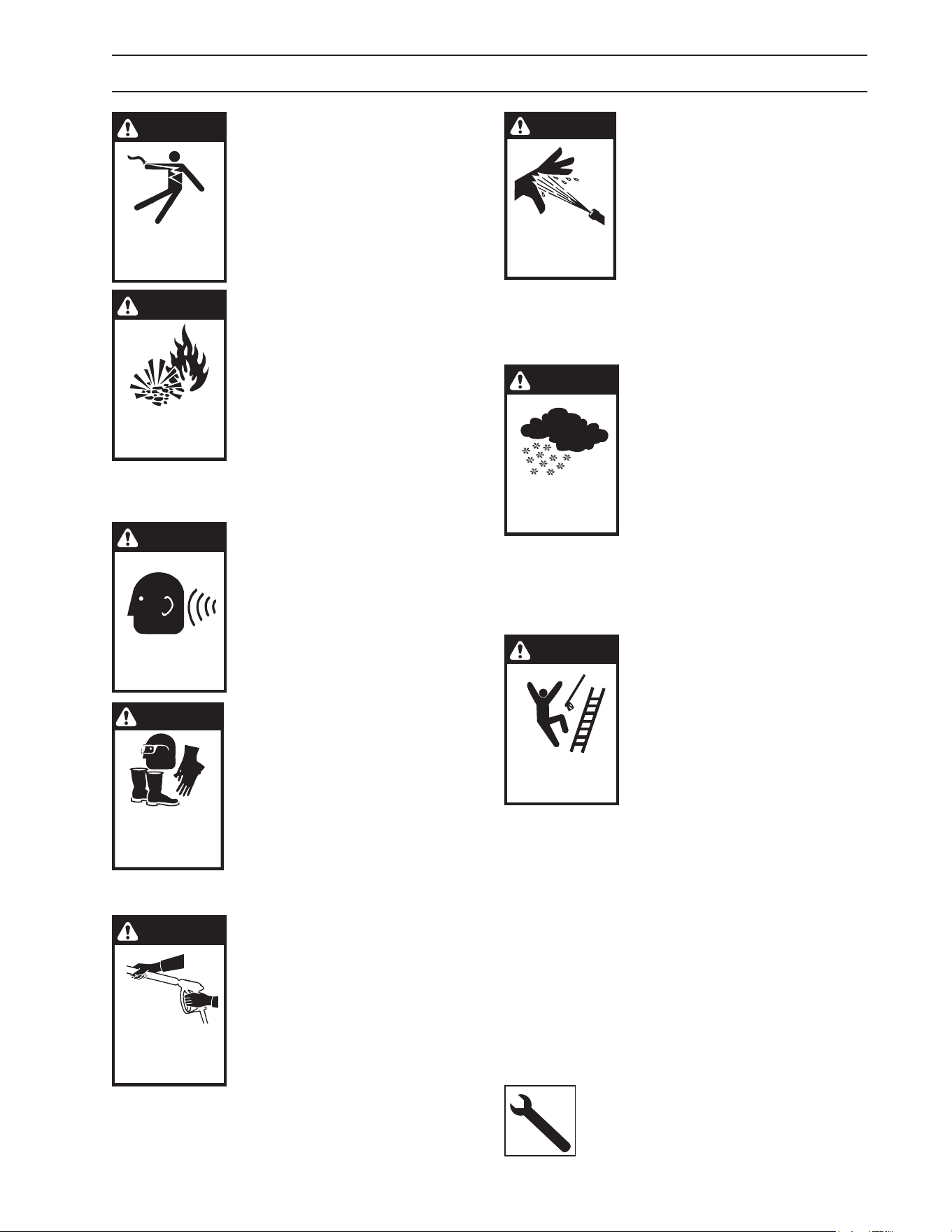
WARNING: To reduce the risk of
injury, read operating
instructions carefully before
using.
1. Read the owner's
manual thoroughly. Failure to
follow instructions could cause
malfunction of the machine and
result in death, serious bodily injury
and/or property damage.
2. Know how to stop the machine and bleed
pressure quickly. Be thoroughly familiar with the
controls.
3. Stay alert — watch what you are doing.
4. All installations must comply with local codes.
Contact your electrician, plumber, utility
company or the selling distributor for specic
details.
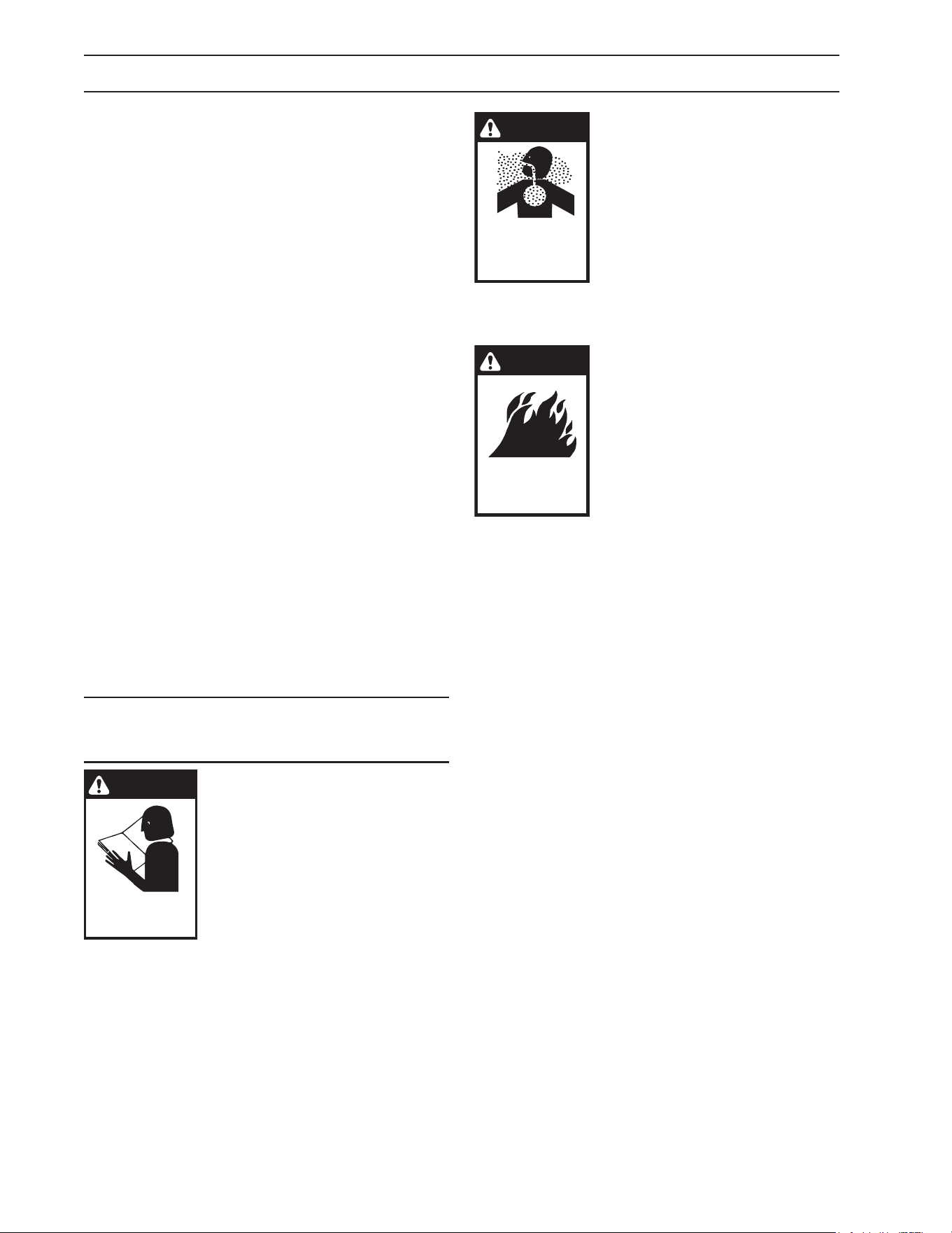
DANGER
RISK OF
ASPHYXIATION.
USE THIS PRODUCT
ONLY IN A WELL
VENTILATED AREA.
WARNING: Risk of asphyxiation.
Use this product only in a well
ventilated area.
5. 5. Avoid installing
machines in small areas or near
exhaust fans. Exhaust contains
poisonous carbon monoxide
gas; exposure may cause loss of
consciousness and may lead to
death. It also contains chemicals
known, in certain quantities, to cause cancer,
birth defects or other reproductive harm.
WARNING
RISK OF FIRE.
DO NOT ADD FUEL
WHEN OPERATING
MACHINE.
WARNING: Risk of re. Do not
add fuel when the product is
operating.
WARNING: Risk of explosion —
Do not spray ammable liquids.
6. Do not place machine near
ammable objects as the engine
is hot.
WARNING: This product contains chemicals
known to the state of California to cause cancer
and birth defects or other reproductive harm.
Operation of this equipment may create sparks
that can start res around dry vegetation. A
spark arrestor may be required. The operator
should contact: Local re agencies for laws
or regulations relating to re prevention
requirements.
7. Allow engine to cool for 1-2 minutes before
refueling. If any fuel is spilled, make sure the
area is dry before testing the spark plug or
starting the engine. (Fire and/or explosion may
occur if this is not done.)
Gasoline engines on mobile or portable equipment
shall be refueled:
a. outdoors;
b. with the engine on the equipment stopped;
c. with no source of ignition within 10 feet of
the dispensing point; and
d. with an allowance made for expansion of the
fuel should the equipment be exposed to a
higher ambient temperature.
In an overlling situation, additional precautions are
necessary to ensure that the situation is handled in a
safe manner.
WARNING: Risk of injury. Disconnect battery
ground terminal before servicing.
8. Transport/repair with fuel tank EMPTY or with
fuel shut-o valve OFF.
Manual, Karcher • 9.807-623.0
5
IMPORTANT SAFETY INFORMATION
DANGER
KEEP WATER
SPRAY AWAY FROM
ELECTRICAL WIRING.
WARNING: Keep wand, hose,
and water spray away from
electric wiring or fatal electric
shock may result.
9. Do not spray water on or
near electrical components.
WARNING
RISK OF EXPLOSION:
DO NOT SPRAY
FLAMMABLE
LIQUIDS.
WARNING: Flammable liquids
can create fumes which can
ignite, causing property damage
or severe injury.
WARNING: Risk of explosion —
Do not spray ammable liquids.
10. Keep operating area clear of all persons.
WARNING
EAR PROTECTION
MUST BE WORN
WARNING: This machine
exceeds 85 db appropriate ear
protection must be worn.
WARNING
USE PROTECTIVE
EYE WEAR
AND CLOTHING
WHEN OPERATING
THIS EQUIPMENT.
WARNING: High pressure spray
can cause paint chips or other
particles to become airborne and
y at high speeds. To avoid
personal injury, eye, hand and
foot safety devices must be
worn.
11. Eye, hand, and foot
protection must be worn when
using this equipment.
WARNING
TRIGGER GUN KICKS
BACK — HOLD WITH
BOTH HANDS
WARNING: Grip cleaning wand
securely with both hands before
starting. Failure to do this could
result in injury from a whipping
wand.
12. To reduce the risk of injury,
close supervision is necessary
when a machine is used near
children. Do not allow children to
operate the pressure washer. This machine
must be attended during operation.
WARNING
RISK OF INJECTION
OR SEVERE INJURY
TO PERSONS. KEEP
CLEAR OF NOZZLE.
WARNING: High pressure
developed by these machines
will cause personal injury or
equipment damage. Keep clear
of nozzle. Use caution when
operating. Do not direct
discharge stream at people, or
severe injury or death will result.
13. Never make adjustments on machine while
in operation.
14. Be certain all quick coupler ttings are secured
before using pressure washer.
WARNING
PROCTECT FROM
FREEZING
WARNING: Protect machine
from freezing.
15. To keep machine in
best operating conditions, it is
important you protect machine
from freezing. Failure to protect
machine from freezing could
cause malfunction of the machine
and result in death, serious bodily
injury, and/or property damage.
Follow storage instructions specied in this
manual.
16. The best insurance against an accident is
precaution and knowledge of the machine.
WARNING
RISK OF INJURY
FROM FALLS WHEN
USING LADDER.
WARNING: Be extremely careful
when using a ladder, scaolding
or any other relatively unstable
location. The cleaning area
should have adequate slopes
and drainage to reduce the
possibility of a fall due to
slippery surfaces.
17. Do not overreach or stand
on unstable support. Keep good footing and
balance at all times.
18. Do not operate this machine when fatigued
or under the inuence of alcohol, prescription
medications, or drugs.
19. Inlet water must be clean fresh water and no
hotter then 90°F.
20. Manufacturer will not be liable for any changes
made to our standard machines or any
components not purchased from us.
21. Do not allow acids, caustic or abrasive uids to
pass through the pump.
22. Never run pump dry or leave spray gun closed
longer than 1-2 minutes.
Follow the maintenance instructions
specied in the manual.
Manual, Karcher • 9.807-623.0
6
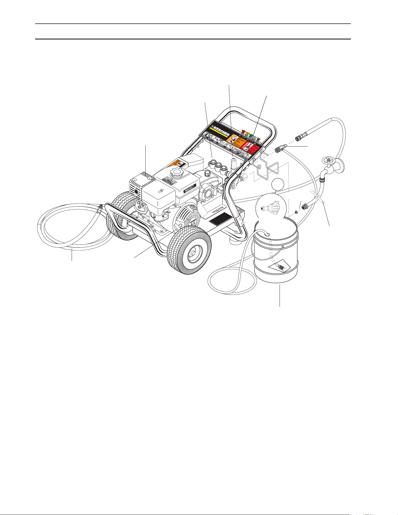
Pump — Develops high pressure.
Starter Grip— Used for starting the engine
manually.
Spray Gun — Controls the application of water and
detergent onto cleaning surface with trigger device.
Includes safety latch.
Detergent Injector — Allows you to siphon and mix
detergents.
Wand — Must be connected to the spray gun.
High Pressure Hose — Connect one end to water
pump discharge nipple (detergent injector nipple)
and the other end to spray gun.
Note: If trigger on spray gun is released for more
than 1-2 minutes, water may leak from pump
protector. Warm water will discharge from pump
protector onto oor. This system prevents
internal pump damage from high temperatures.
COMPONENT IDENTIFICATION
Starter Grip
High Pressure
Hose
Pump
Straight
Through
Wand
Garden Hose
(not included)
Inlet
Screen
Unloader
Detergent
Bucket (not
included)
Detergent
Injector
Pump Protector
Pressure
Nozzle
Manual, Karcher • 9.807-623.0
7
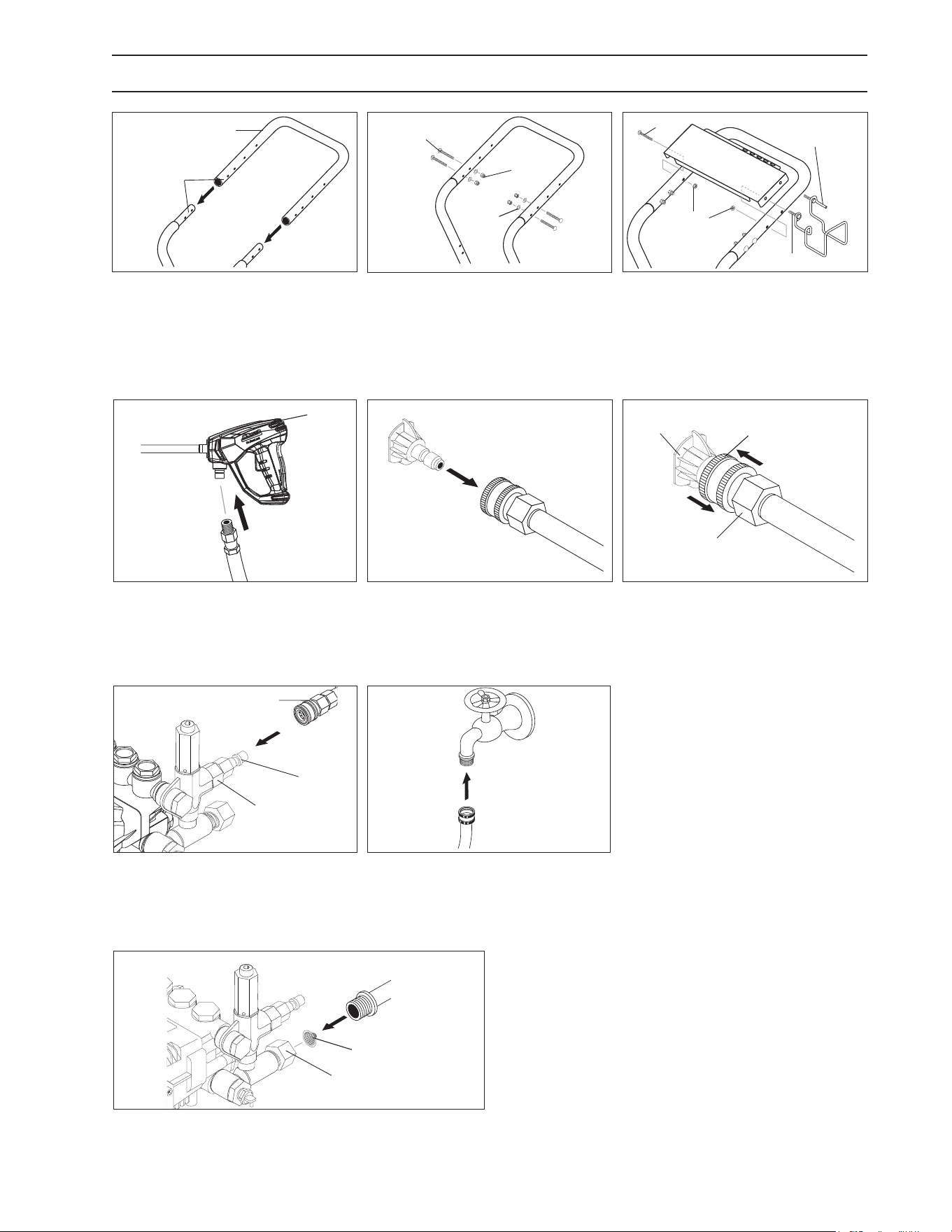
Alignment
Holes
Handle
Frame
Assy
STEP 1: Attach the handle to the
frame of the pressure washer.
Note: It may be necessary to move
the handle supports from side to
side in order to align the handle so
it will slide over the frame supports.
Pressure
Nozzle
Wand
Coupler
Wand
Collar
STEP 6: Release the coupler
collar and push the nozzle and the
collar until the collar clicks or locks.
Pull the nozzle to make sure it is
secure.
ASSEMBLY INSTRUCTIONS
Carriage
Bolt
Nut
Washer
STEP 2: Insert the carriage bolt
through the holes from the outside
of the unit and attach a nut from
the inside of the machine. Tighten
nuts.
Studs
Nut
Hose/Spray Gun
Storage Bracket
Bolts
STEP 3: Attach the spray gun/hose
storage handle, and bracket to
handle. Tighten nuts.
Pump
Discharge
Fitting
High Pressure Hose
Coupler
Collar
STEP 7: Connect high pressure
hose to pump discharge tting.
Push coupler collar forward until
secure.
Cold
Water
Source
Garden
Hose
STEP 8: Connect garden hose to a
clean cold water source and open
supply valve completely. NEVER
use hot water.
Pump
Water Inlet
Garden
Hose
Inlet Screen
STEP 9: Connect the garden hose to pump water
inlet. Inspect inlet screen.
CAUTION: Do not run the
pump without water or pump damage will result.
Safety
Latch
Spray
Gun
High Pressure
Hose
STEP 4: Attach the high pressure
hose to the spray gun using teon
tape on hose threads.
Wand
Coupler
Pressure
Nozzle
STEP 5: Pull the spring-loaded
collar of the wand coupler back
to insert your choice of pressure
nozzle.
Manual, Karcher • 9.807-623.0
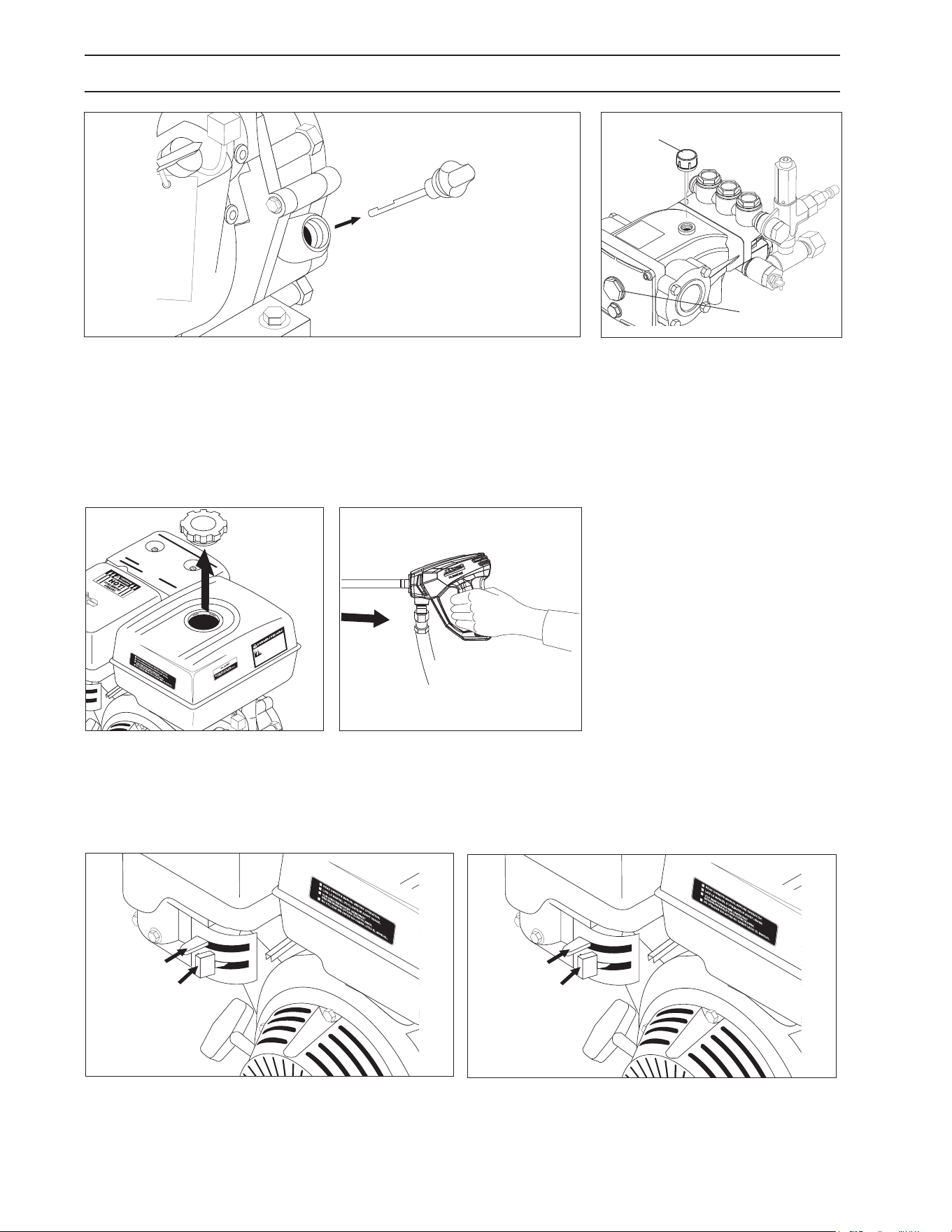
8
Engine Oil
Dipstick
STEP 1: Check engine oil level. Oil level should be level with the bottom
of the oil ller neck. Be sure the machine is level when checking the oil
level. (Refer to the engine's operating manual included with machine.)
We recommend that the oil be changed after the rst 5 hours of use,
then once every 50 hours. Note: Improper oil levels will cause low oil
sensor to shut o engine. IMPORTANT! Do not run engine with high
or low oil levels as this will cause engine damage.
OPERATING INSTRUCTIONS
Pump Oil
Dipstick
Oil Window
STEP 2: Remove shipping cap
and install oil dipstick. Check
pump oil level by using dipstick
or observe oil level in oil window
(if equipped). Use 30 wt. (non
detergent) oil.
Gas
Tank
STEP 3: Fill gas tank with
unleaded gasoline. Do not use
leaded gasoline.
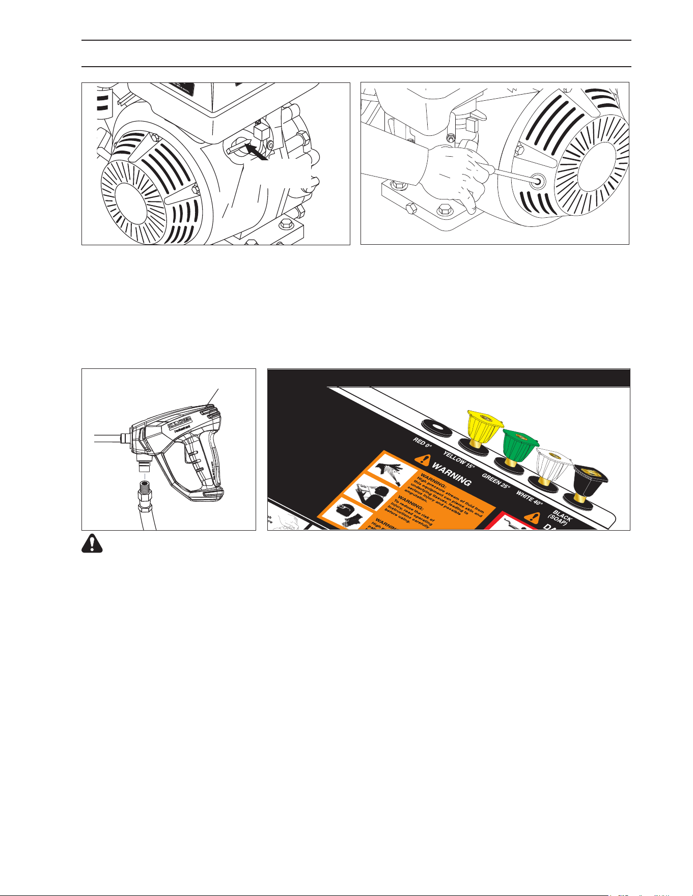
STEP 4: Trigger the spray gun to
eliminate trapped air then wait for
a steady ow of water to emerge
from the spray nozzle.
Fuel
Valve
Choke
STEP 5: Move the fuel shut-o valve to the "On"
position. When the engine is not in use, leave the
fuel valve in the "OFF" position.
Choke
Lever
Fuel
Valve
STEP 6: Move the choke lever to the "Choke"
position (on a warm engine, leave the choke lever
in the run position). Move the choke lever to the
"Closed" position. To restart a warm engine, leave the
choke lever in the "Open" position.
Manual, Karcher • 9.807-623.0
9
OPERATING INSTRUCTIONS
On-O
Switch
STEP 7: Turn the engine switch to "On" position.
On Briggs engines, move the throttle lever to "Fast"
position, shown on engine as a rabbit.
STEP 8: Pull the starter grip. If the engine fails to
start after 2 pulls, squeeze the trigger gun to release
pressure and repeat step. Return starter gently. After
the engine warms up enough to run smoothly, move
choke to run position and throttle to fast position.
CAUTION: Small engines may kick back. Do not
hold pull starter grip tightly in hand.
Safety
Latch
WARNING! Never replace
nozzles without engaging the
safety latch on the spray gun
trigger.
NOZZLES
The four color-coded quick connect nozzles provide a wide array of
spray widths from 15° to 40° and are easily accessible when placed in
the convenient rubber nozzle holder, which is provided on the front of the
machine.
NOTE: For a more gentle rinse, select the white 40° or green 25°
nozzle. To scour the surface, select the yellow 15° nozzle. To apply
detergent select the black nozzle.
Manual, Karcher • 9.807-623.0
10
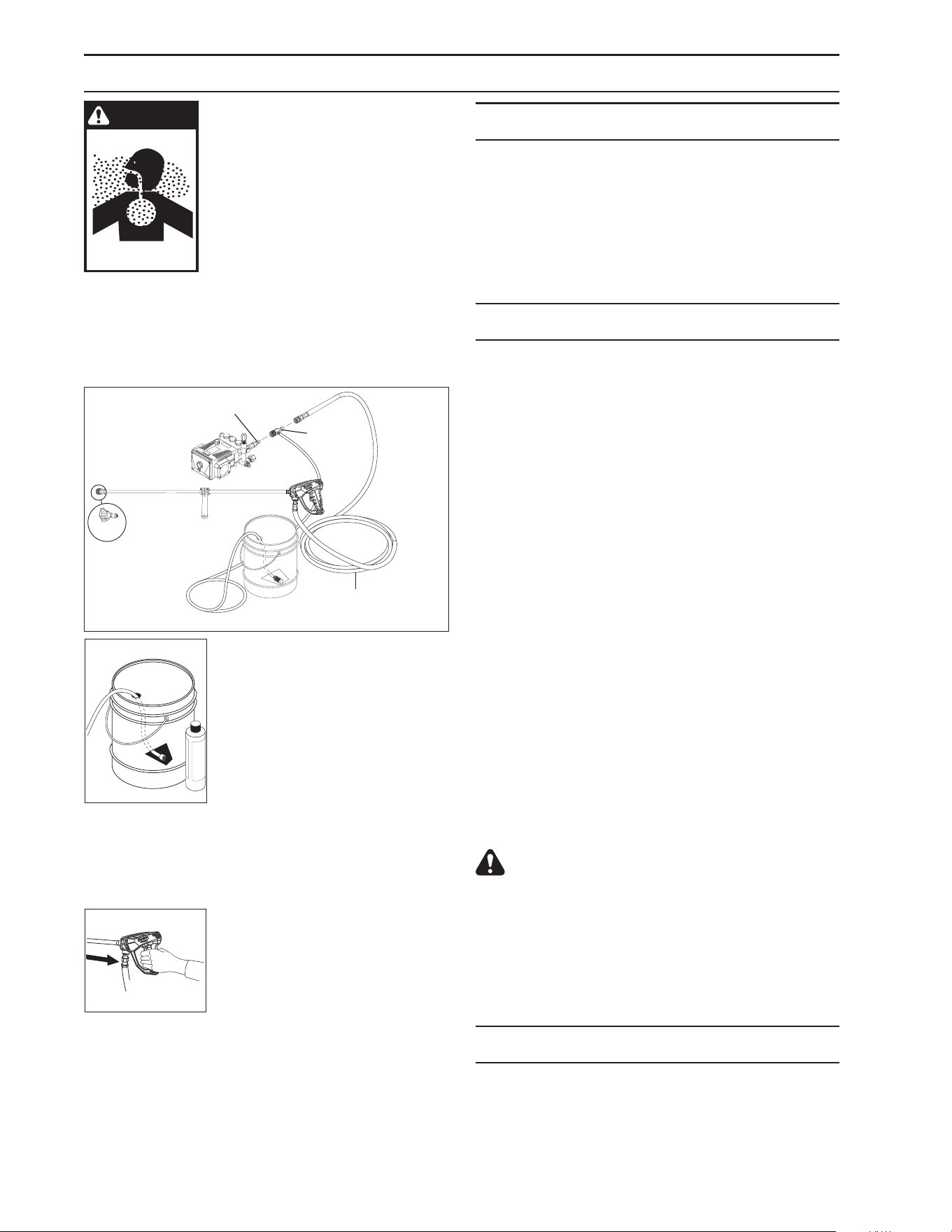
WARNING
WARNING: Some detergents
may be harmful if inhaled or
ingested, causing severe
nausea, fainting or poisoning.
The harmful elements may
cause property damage or
severe injury.
STEP 1: Connect detergent injector to discharge
nipple on machine. Connect high pressure hose
to injector with quick coupler. (Check to make sure
locking couplers are in proper position before
applying water pressure).
Detergent
Injector
Discharge
Nipple
High Pressure
Hose
STEP 2: Use detergent designed
specically for pressure washers.
Household detergents could
damage the pump. Prepare
detergent solution as required by
the manufacturer. Fill a container
with pressure washer detergent.
Place the lter end of detergent
suction tube into the detergent
container.
STEP 3: With safety latch on spray gun engaged,
secure black detergent nozzle into quick coupler.
NOTE: Detergent cannot be applied using yellow,
green or white nozzles.
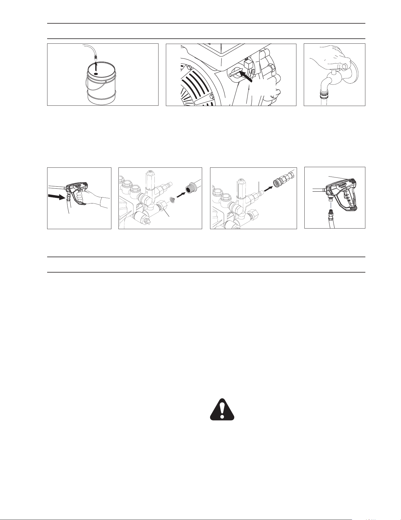
STEP 4: With the engine running,
pull trigger to operate machine.
Liquid detergent is drawn into the
machine and mixed with water.
Apply detergent to work area.
Do not allow detergent to dry on
surface.
IMPORTANT: You must ush the detergent
injection system after each use by placing the
suction tube into a bucket of clean water, then
run the pressure washer in low pressure for 1-2
minutes.
THERMAL PUMP PROTECTION
If you run the engine on your pressure washer for
1-2 minutes without pressing the trigger on the
spray gun, circulating water in the pump can reach
high temperatures. When the water reaches this
temperature, the pump protector engages and
cools the pump by discharging the warm water onto
the ground. This thermal device prevents internal
damage to the pump.
CLEANING TIPS
Pre-rinse cleaning surface with fresh water. Place
detergent suction tube directly into cleaning solution
and apply to surface at low pressure (for best results,
limit your work area to sections approximately 6 feet
square and always apply detergent from bottom
to top). Allow detergent to remain on surface 1-3
minutes. Do not allow detergent to dry on surface.
If surface appears to be drying, simply wet down
surface with fresh water. If needed, use brush to
remove stubborn dirt. Rinse at high pressure from
top to bottom in an even sweeping motion keeping
the spray nozzle approximately 1 foot from cleaning
surface. Use overlapping strokes as you clean and
rinse any surface. For best surface cleaning action
spray at a slight angle.
Recommendations:
• Before cleaning any surface, an inconspicuous
area should be cleaned to test spray pattern and
distance for maximum cleaning results.
• If painted surfaces are peeling or chipping,
use extreme caution as pressure washer may
remove the loose paint from the surface.
• Keep the spray nozzle a safe distance from the
surface you plan to clean. High pressure wash a
small area, then check the surface for damage.
If no damage is found, continue to pressure
washing.
CAUTION - Never use:
• Bleach, chlorine and other corrosive chemicals
• Liquids containing solvents (i.e., paint thinner,
gasoline, oils)
• Tri-sodium phosphate products
• Ammonia products
• Acid-based products
• These chemicals will harm the machine and will
damage the surface being cleaned.
RINSING
It will take a few seconds for the detergent to clear.
Apply safety latch to spray gun. Remove black soap
nozzle from the quick coupler. Select and install
the desired high pressure nozzle. NOTE: You can
also stop detergent from owing by simply removing
detergent siphon tube from bottle.
DETERGENTS & GENERAL CLEANING TECHNIQUES
Manual, Karcher • 9.807-623.0
11
SHUTTING DOWN AND CLEAN-UP
STEP 1: Remove detergent suction
tube from container and insert into
one gallon of fresh water. Slide nozzle
forward for low pressure or to connect
black detergent nozzle into wand
quick coupler. Pull trigger on spray
gun and siphon water for one minute.
CAUTION: Always store your pressure washer
in a location where the temperature will not fall
below 32°F (0°C). The pump in this machine
is susceptible to permanent damage if frozen.
FREEZE DAMAGE IS NOT COVERED BY
WARRANTY.
1. Stop the pressure washer, squeeze spray gun
trigger to release pressure.
2. Detach water supply hose and high pressure hose.
3. Turn on the machine for a few seconds,
until remaining water exits. Turn engine o
immediately.
4. Drain the gas and oil from the engine.
5. Do not allow high pressure hose to become
kinked.
6. Store the machine and accessories in a room
which does not reach freezing temperatures.
CAUTION: Failure to follow the above directions
will result in damage to your pressure washer.
When the pressure washer is not being operated or is
being stored for more than one month, follow these
instructions:
1. Replenish engine oil to upper level.
2. Drain gasoline from fuel tank, fuel line, fuel valve
and carburetor.
3. Pour about one teaspoon of engine oil through
the spark plug hole, pull the starter grip several
times and replace the plug. Then pull the starter
grip slowly until you feel increased pressure
which indicates the piston is on its compression
stroke and leave it in that position. This closes
both the intake and exhaust valves to prevent
rusting of cylinder.
4. Cover the pressure washer and store in a clean,
dry place that is well ventilated away from open
ame or sparks. NOTE: The use of a fuel
additive, such as STA-BIL
®
, or an equivalent, will
minimize the formulation of fuel deposits during
shortage. Such additives may be added to the
gasoline in the fuel tank of the engine, or to the
gasoline in a storage container.
After Extended Storage
CAUTION: Prior to restarting, thaw out
any possible ice from pressure washer
hoses, spray gun or wand.
Engine Maintenance
During the winter months, rare atmospheric conditions
may develop which will cause an icing condition in the
carburetor. If this develops, the engine may run rough,
lose power and may stall. This temporary condition
can be overcome by deecting some of the hot air
from the engine over the carburetor area. NOTE:
Refer to the engine manufacturer's manual for
service and maintenance of the engine.
STORAGE
On-O
Switch
STEP 2: Turn o the engine.
STEP 3: Turn
o water supply.
STEP 4: Press trigger
to release water
pressure.
Pump Water
Inlet
STEP 5: Disconnect the
garden hose from the water
inlet on the machine.
High Pressure
Outlet
STEP 6: Disconnect the high
pressure hose from high
pressure outlet.
Safety
Latch
STEP 7: Engage
the spray gun safety
lock.

Manual, Karcher • 9.807-623.0
12
PROBLEM POSSIBLE CAUSE SOLUTION
LOW OPERATING
PRESSURE
Faulty pressure gauge Install new gauge.
Insucient water supply
Use larger supply hose; clean lter at
water inlet.
Old, worn or incorrect spray nozzle
Match nozzle number to machine and/or
replace with new nozzle.
Belt slippage Tighten or replace; use correct belt.
Plumbing or hose leak
Check plumbing system for leaks. Re-tape
leaks with teon tape.
Faulty or mis-adjusted unloader valve
Adjust unloader for proper pressure. Install
repair kit when needed.
Worn packing in pump Install new packing kit.
Fouled or dirty inlet or discharge valves
in pump
Clean inlet and discharge valves.
Worn inlet or discharge valves Replace with valve kit.
Obstruction in spray nozzle Remove obstruction.
Leaking pressure control valve Rebuild or replace as needed.
Slow engine RPM Set engine speed at proper specications.
Pump sucking air
Check water supply and possibility of air
seepage.
Valves sticking Check and clean or replace if necessary.
Unloader valve seat faulty Check and replace if necessary.
FLUCTUATING
PRESSURE
Valves worn Check and replace if necessary.
Blockage in valve
Check and replace if necessary.
Pump sucking air
Check water supply and air seepage at
joints in suction line.
Worn piston packing Check and replace if necessary.
TROUBLESHOOTING
Unloader valves are preset and tested at the factory
before shipping. Occasional adjustment of the
unloader may be necessary to maintain correct
pressure.
Start with the valve set at its lowest spring tension.
Raise pressure by turning adjusting knob clockwise
until pressure is at the desired position. Do not
overtighten.
ADJUSTING UNLOADER VALVES
Open and close spray gun to be sure pressure is
correct. Raise or lower pressure by adjusting the
knob.
Do not by-pass more than 1-2 minutes when by-
passing to the suction side of the pump.
Manual, Karcher • 9.807-623.0
13
PREVENTATIVE MAINTENANCE
This pressure washer was produced with the best available materials and quality craftsmanship. However,
you as the owner have certain responsibilities for the correct care of the equipment. Attention to regular
preventative maintenance procedures will assist in preserving the performance of your equipment. Contact
your dealer for maintenance. Regular preventative maintenance will add many hours to the life of your
pressure washer. Perform maintenance more often under severe conditions.
Maintenance Operation Every 8 Hrs
or Daily
25 Hrs or
Weekly
50 Hrs or
Monthly
100 Hrs or
Yearly
Yearly
Check Oil
Pump X
Engine X
Change Oil
Pump X
Engine X
Air Cleaner Check Clean
Spark Plug X
Check Valve Clearance X
Fuel Tank Filter X
Water Filter/Clean Check X
NOTE: Read engine manual for any maintenance or service questions.
OIL CHANGE RECORD
Check pump oil and engine oil level before rst use of your new pressure washer.
Date Oil Changed
Month/Day/Year
No. of Operating Hours
Since Last Oil Change
Brand Name and
Type of Oil (see above)
Manual, Karcher • 9.807-623.0
14
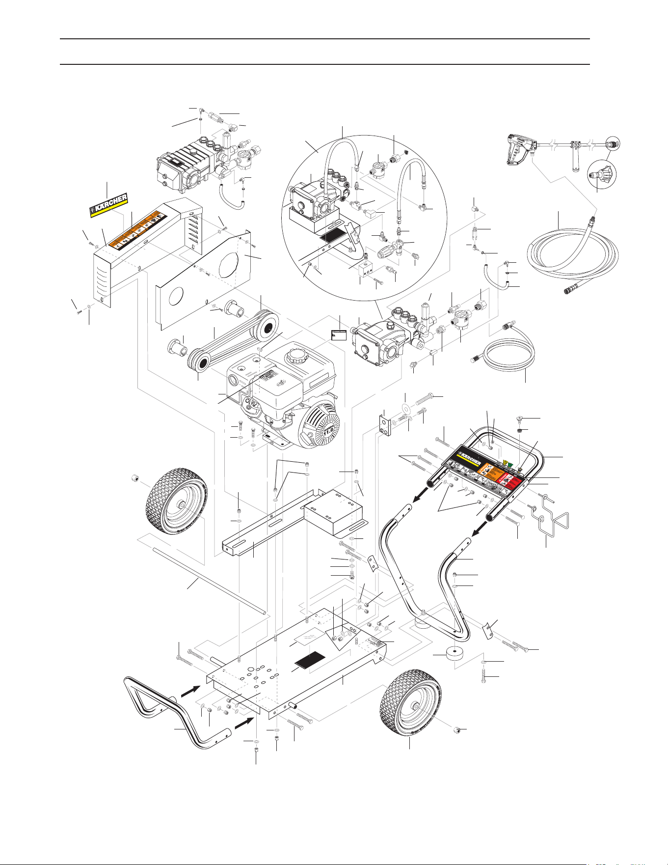
EXPLODED VIEW - 1.575-152.0,154.0,155.0,480.0
17
18
9
10
11
12
10
11
16
13
15
31
19
27
29
6
28
30
1
59
58
58
2
3
4
6
5
57
40
41
42
45
43
39
38
37
32
36
32
35
44
34
49
51
25
24
60
61
54
11
14
47
52
50
48
23
56
55
59
22
21
53
11
20
10
63
33
58
58
20
46
28
28
28
62
61
60
61
60
6
58
59
57
11
10
58
59
64
65
66
69
7
90
67
8
10
11
22
21
68
70
70
73
76
43
81
72
75
74
89
41
45
44
77
88
87
82
78
84
79
26
80
Pump
155.0
39
38
36
37
32
Pump
152.0
42

Manual, Karcher • 9.807-623.0
15
EXPLODED VIEW PARTS LIST - 1.575-152.0,154.0,155.0,480.0
ITEM PART NO. DESCRIPTION QTY
1 9.802-064.0 Grommet, Rubber, 5
Nozzle Holder
2 8.925-057.0 Handle, Grab, Grey, OS 1
3 9.800-723.0 Label, Cold Water Handle 1
4 9.803-126.0 Plate, Warning/Instruction, Black 1
5 9.803-098.0 Hanger, Hose/Wand 1
6 9.802-706.0 Bolt, Carriage, 1/4"-20 x 1-3/4", 6
Zinc
7 9.800-110.0 Label Karcher Logo 1
8 9.802-778.0 Nut, 5/16" Whiz Loc Flange 2
9 8.925-058.0 Handle, Lower Grab, Grey, OS 1
10 9.197-003.0 Nut, 3/8" ESNA, NC 10
11 9.802-807.0 Washer, 3/8" SAE, Flat 14
12 9.803-114.0 Retainer Bracket, Handle, Black 2
13 9.802-728.0 Bolt, 3/8" x 2" NC, HH 4
14 9.802-727.0 Bolt, 3/8" x 1-3/4", Tap 4
15 9.802-817.0 Washer, 3/8" x 1", Steel 2
16 9.802-066.0 Pad, Soft Rubber 2
17 9.802-782.0 Collar, 5/8" Bore Shaft, 3010 2
18 8.758-460.0 Wheel 12 In. Rim Steel 2
19 9.803-115.0 Frame Assy, Large, Black 1
20 9.802-712.0 Bolt, 5/16" x 1-3/4", NC, 4
Carriage, Zinc
21 9.802-776.0 Nut, 5/16", ESNA, NC 4
22 8.718-980.0 Washer, 5/16" Flat, SAE 4
23 8.911-226.0 Axle, 5/8" x 27" L 1
24 8.917-893.0 Assy Black, Slider Pump / Belt 1
Guard Mount
25 8.917-886.0 Plate, Belt Guard Front Cover 1
26 Hose and Spray Gun, See Assy Page
27 9.803-118.0 Bracket, Take Up, CW, Black 1
28 9.802-700.0 Screw, 1/4" x 3/4" HH NC 8
29 9.802-809.0 Washer, 1/2", Flat, SAE 1
30 9.802-740.0 Bolt, 1/2" x 3-1/2" HEX 1
31 9.802-730.0 Bolt, 3/8" x 2-1/4", HH 2
32 6.390-126.0 Clamp, Hose, .46-54 ST 2
33 9.802-813.0 Washer, 5/16" Lock
(152.0, 480.0) 4
9.802-816.0 Washer, 7/16" Lock, Split 4
(154.0,155.0)
34 9.802-225.0 Injector Assy., Detergent, 1
Non-Adj, 3-5 GPM, 0.083
35 9.802-254.0 Hose, 1/4", Push-On, 1 ft.
Fuel Line (All except 155.0)
36 8.706-958.0 Barb, 1/4" Barb x 1/4" ML Pipe, 1
90° (All Except 155.0)
ITEM PART NO. DESCRIPTION QTY
37 8.706-955 Hose Barb, 1/4" Barb x 1/8" 1
ML Pipe, 90°
(All Except 155.0 & 154.0)
8.706-940.0 Hose Barb, 1/4" Barb x 1/8" 1
ML Pipe (154.0)
38 9.802-190.0 Valve, E-Z Start, 1
3/8" MPT x 1/8" FPT
9.804-065.0 Valve, E-Z Start, 1
1/4" MPT x 1/8" FPT (152.0)
39 8.706-207.0 Elbow, 3/8", Street 1
8.706-200.0 Elbow, 1/4", Street (152.0) 1
40 9.804-025.0 Pump Protector, 1/4"PTP 1
(152.0)
8.707-256.0 Pump Protector, 1/2"PTP 1
140DEG, P/N 1005 (154.0)
41 Pump, See Specications Pages
42 Unloader, See Specications Pages
43 9.802-170.0 Coupler, 3/8"Plug, Female
Steel/Zinc (152.0) Only 1
44 9.802-146.0 Swivel, 1/2" MP x 3/4" GHF 1
w/Strainer
45 9.802-163.0 Strainer, 1/2" PA, Inline Plastic 1
46 9.800-008.0 Label, Danger Cool Engine 1
47 Engine, See Specications Pages
48 Engine Pulley, See Specications Pages
49 Engine Bushing, See Specications Pages
50 Belts, See Specications Pages
51 Pump Bushing, See Specications Pages
52 Pump Pulley, See Specications Pages
53 8.925-059.0 Handle, Bumper, Grey, OS 1
54 9.800-006.0 Label, Hot/Caliente w/Arrows, 1
Warning
55 8.932-968.0 Label, Intended For Outdoor Use 1
56 9.800-034.0 Label, Clear Lexan 1
57 8.712-338.0 Nozzle, SAQCMEG 1503.5, 1
Yellow (152.0)
8.712-339.0 Nozzle, SAQCMEG, 2503.5, 1
Green (152.0)
8.712-340.0 Nozzle, SAQCMEG 4003.5, 1
White (152.0)
8.712-360.0 Nozzle, SAQCMEG 1504.0, 1
Yellow (154.0, 480.0)
8.712-370.0 Nozzle, SAQCMEG, 2504.0, 1
Green (154.0, 480.0)
8.712-380.0 Nozzle, SAQCMEG 4004.0, 1
White (154.0, 480.0)
8.712-333.0 Nozzle, SAQCMEG 1503.0, 1
Yellow (155.0)
8.712-334.0 Nozzle, SAQCMEG, 2503.0, 1
Green (155.0)
8.712-335.0 Nozzle, SAQCMEG 4003.0, 1
White(155.0)

Manual, Karcher • 9.807-623.0
16
EXPLODED VIEW PARTS LIST - 1.575-152.0,154.0,155.0,480.0
ITEM PART NO. DESCRIPTION QTY
58 9.802-802.0 Washer, 1/4" Flat 10
59 9.802-773.0 Nut, 1/4" ESNA 8
60 8.718-980.0 Washer, 5/16" Flat 4
61 9.802-776.0 Nut, 5/16" ESNA 4
62 9.802-802.0 Washer, 1/4" Flat, SAE 6
63 9.802-741.0 Bolt, 8mm x 16mm Hex (152.0) 4
9.802-744.0 Bolt, 10mm x 20mm 4
(154.0,155.0)
64 8.706 -860.0 Tee, 1/2" Branch (155.0) 1
8.706-854.0 Tee, 1/4" Branch (152.0) 1
65 8.706-984.0 Adapter, 1/2" x 1/2" (152.0) 1
66 9.800-049.0 Label, Manufacturer's Cleaning 1
Solution
67 9.802-959.0 Key, .247 Sqr. x 2.125" 1
68 9.802-311.0 Nozzle, Compl., Detergent 1
69 9.800-036.0 Label, Warning, Pictoral, Small 1
70 8.718-980.0 Washer, 5/16" Flat (152.0) 4
9.802-807.0 Washer, 3/8" Flat (155.0) 4
71 8.750-300.0 Unloader, VRT3 Ez Start (155.0) 1
72 9.802-870.0 Block, Unloader, 1
3/8" x 3/8" 1.25 Steel (155.0)
73 9.802-728.0 Bolt, 3/8" x 2", NC HH (155.0) 2
74 9.802-807.0 Washer, 3/8" SAE, Flat (155.0) 2
75 9.197-003.0 Nut, 3/8" ESNA NC (155.0) 2
76 8.705-974.0 Nipple, 3/8" Hex Steel (155.0) 1
77 9.802-129.0 Elbow, 3/8" x 1/2" JIC (155.0) 1
78 8.706-860.0 Street Tee, 1/2" (155.0) 1
79 9.802-128.0 Nipple, 1/2" x 1/2" JIC (155.0) 1
80 9.802-259.0 Hose, Push-on 1/2" (155.0) 15"
81 8.707-254.0 Pump Protector, 3/8" PTP 1
(155.0)
82 9.802-036.0 Nipple, 1/2" JIC, 3/8" Pipe 1
(155.0)
83 9.802-810.0 Washer, 5/8" Flat 2
84 9.802-151.0 Swivel, 1/2" JIC, Female, 2
Push-On (155.0)
85 9.802-959.0 Key, .247" Sqr. x 2.125" 1
86 9.800-036.0 Label, Warning, Pictoral, Small 1
87 9.802-039.0 Elbow, 1/2" JIC, 3/8", 90° 1
(155.0)
88 8.918-422.0 Hose, 3/8" x 20", 2 Wire, 1
Pressure Loop (155.0)
89 8.706-829.0 Elbow, 1/2"" Street, Brass 1
90 8.917-889.0 Plate, Belt Guard
Back Cover 1
8.920-542.0 Black Plate Belt Guard
(152.0, 480.0) 1

Manual, Karcher • 9.807-623.0
17
Model GPM
Pressure
(PSI)
Nozzle
Size Pump
Pump
Part No.
Unloader
Part No. Engine
Engine
Part No.
Pump
Pulley
Pump Pulley
Part No.
1.575-152.0 3.0 3000 3.5 KBP3030R 8.929-255.0 8.923-921.0 GX270 (270cc) 8.759-119.0 2BK80 9.802-389.0
1.575-154.0 3.7 3500 4.0 KM4035R.3 8.751-189.0 9.175-018.0 GX390 (390cc) 8.759-120.0 2BK90H 8.715-593.0
1.575-155.0 3.0 4000 3.0 KM3540R.3 8.751-186.0 8.750-300.0 GX390 (390cc) 8.759-120.0 2BK80H 9.802-389.0
1.107-408.0 3.5 3000 4.0 KM3840R.3 8.933-149.0 8.750-299.0 GX270 (270cc) 8.759-119.0 2BK80H 9.802-389.0
SPECIFICATIONS

Manual, Karcher • 9.807-623.0
18
SPECIFICATIONS
Model
Pump
Bushing
Bushing Part
No.
Engine
Pulley
Pulley
Part No.
Engine
Bushing
Bushing
Part No.
Belt
Size
Belt
Part No.
1.575-152.0 24MM 9.802-402.0 2BK40H 9.802-384.0 HX1" 9.802-399.0 BX38 (2) 9.802-417.0
1.575-154.0 24MM 9.802-402.0 2BK32H 9.802-381.0 HX1" 9.802-399.0 BX39 (2) 9.802-418.0
1.575-155.0 24MM 9.802-402.0 2BK40H 9.802-384.0 HX1" 9.802-399.0 BX38 (2) 9.802-417.0
1.107-408.0 24MM 9.802-402.0 2BK36H 9.802-383.0 HX1" 9.802-399.0 BX27 (2) 8.715-698.0
Manual, Karcher • 9.807-623.0
19
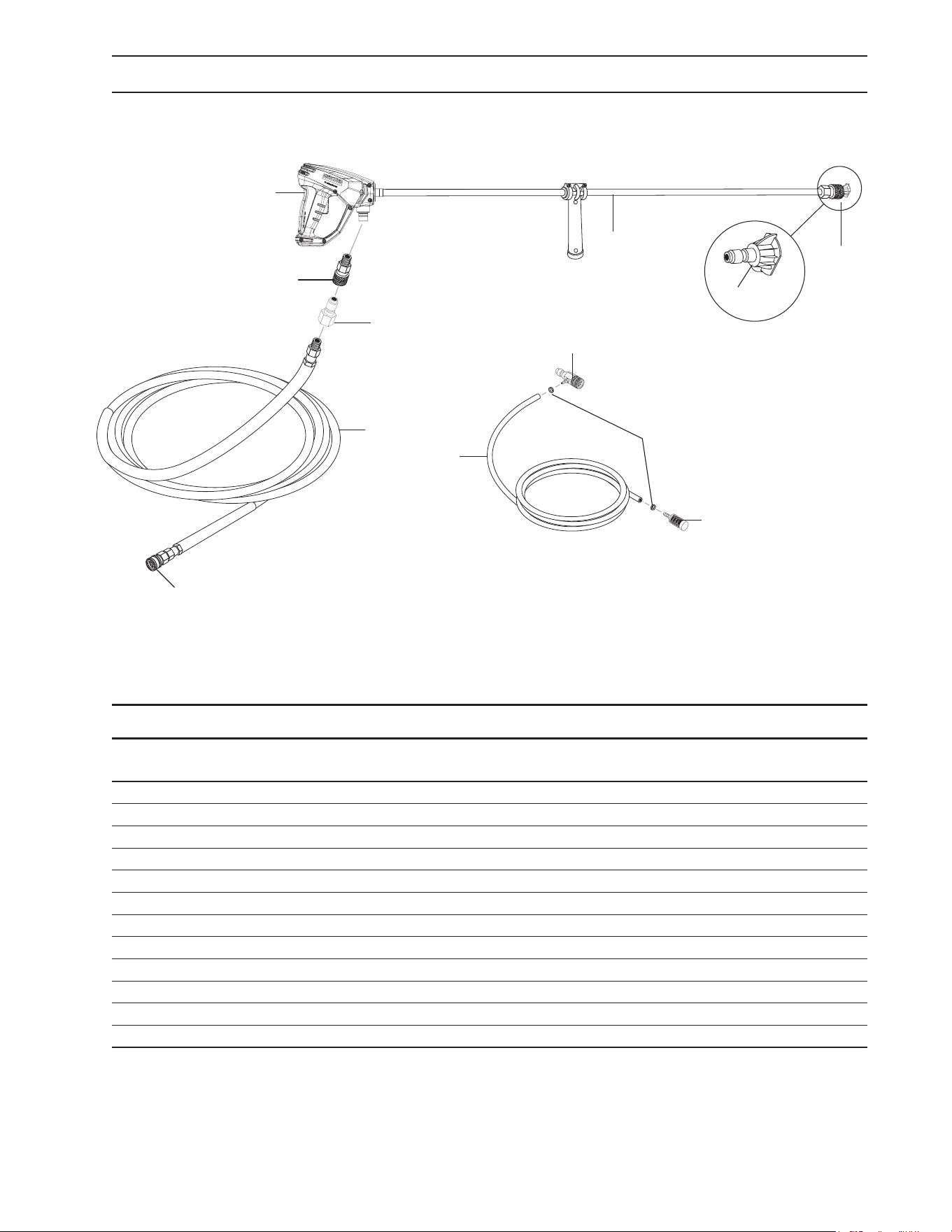
HOSE & SPRAY GUN ASSEMBLY PARTS LIST
HOSE & SPRAY GUN ASSEMBLY
ITEM PART NO. DESCRIPTION QTY
1 9.802-219.0 Wand Assy., Side Grip w/1/4" Coupler, 35-1/2" 1
2 4.775-054.0 EASYForce Advanced KNA 1
3 9.802-164.0 Coupler, 1/4” Female, Brass 1
4 Nozzle, See Breakdown for Part Numbers
5 8.925-130.0 Hose, 3/8" X 50' 1W 4000PSI SW/SO/CPL 1
6 9.802-166.0 Coupler, 3/8" Female, Brass 1
7 9.802-216.0 Injector, Chemical, Non-Adjust, 3-5 GPM, .083 1
8 6.390-126.0 Clamp, Hose 2
9 9.802-251.0 Tube, 1/4" x 1/2" Clear Vinyl 6 ft.
10 8.707-057.0 TStrainer, Plastic, 1/4" Hose Barb 1
11 9.802-170.0 Nipple 3/8 x 3/8 NPT Fem (155.0 Only) 1
12 9.802-169.0 Coupler 3/8" Male Brass (155.0 Only) 1
3
4
1
2
5
6
10
8
9
7
11
12
Manual, Karcher • 9.807-623.0
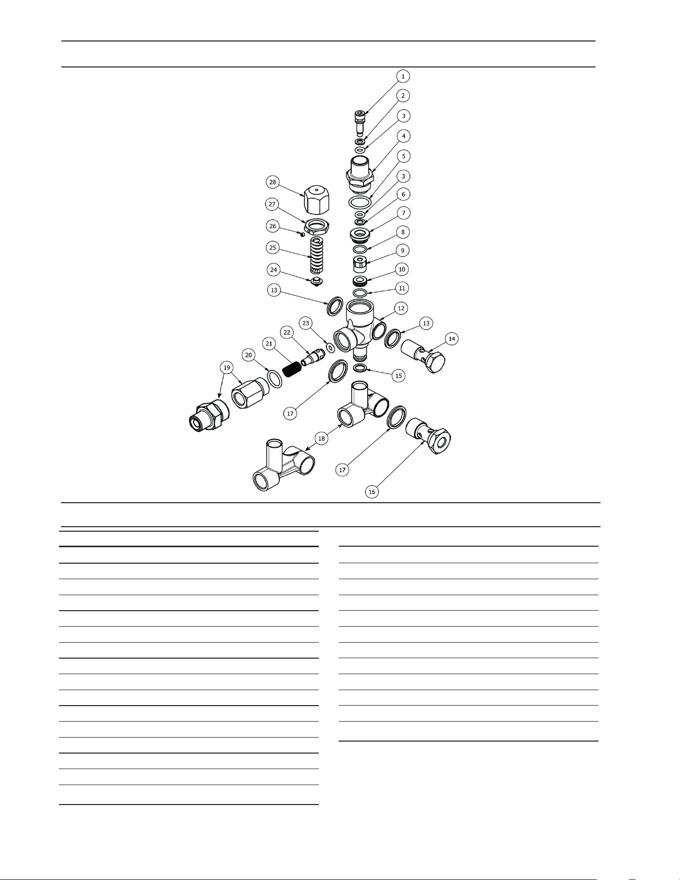
20
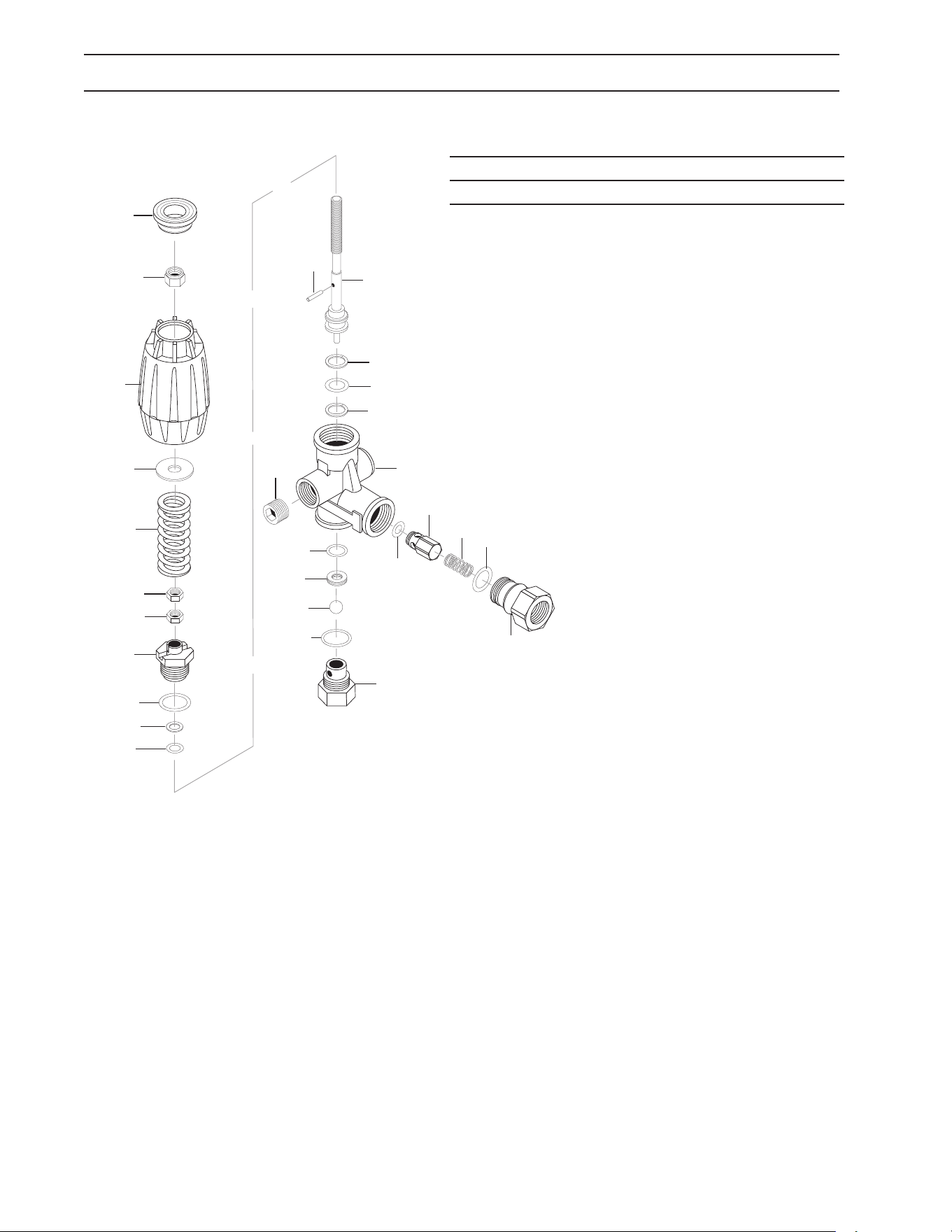
VRT3 UNLOADER EXPLODED VIEW AND PARTS LIST
8.750-300.0, 8 GPM, 4500 PSI EZ Start
Unloader Adjustment Procedures
1. Remove lock nut (Item 19).
2. Remove adjustment knob (Item 24).
3. Loosen the two (2) nuts (Item 20), move them upward on stem (Item 3) until you see 4 or more threads
below the nut.
4. Re-attach adjusting knob (Item 24).
5. Start machine. Open the trigger of the spray gun. Increase pressure by turning adjustment knob (Item 24)
clockwise until pressure is at the desired operating pressure.
6. Remove the adjustment knob (Item 24), tighten the lower nut (Item 20) tightly against the upper nut (Item
20). Re-attach adjustment knob (Item 24) and screw down until contact is made with the nuts (Items 20).
Screw down lock nut (Item19) onto the stem (Item 3) until the threads cut into the nylon insert of the lock
nut (Item 19).
*If adjustment knob (Item 24) DOES NOT make contact with upper nut (Items 20), remove adjusting knob
(Item 24), re-adjust (raise) nuts (Items 20) on stem (Item 3) and re-attach adjustment knob (Item 24), then
repeat step #6.
**If adjustment knob (Item 24) DOES make contact with upper nut; release the trigger of the spray gun and
watch the pressure gauge for the pressure increase (“spike”). This “spike” SHOULD NOT exceed 500 psi
above the operating pressure. If “spike” pressure exceeds the 500 psi limit, remove the adjusting knob (Item
24) and re-adjust (lower) the nuts (Items 20).
1
3
5
2
4
6
7
9
11
8
10
12
13
15
17
14
16
18
19
20
22
20
21
23
24
25
1
10
ITEM PART NO. DESCRIPTION QTY
14
8.750-713.0 OUTLET FITTING 1
24
8.750-712.0 KNOB, UNLOADER 1
8.750-710.0 REPAIR KIT, VRT3, 4500 PSI
(KIT ITEMS: 1, 4, 8-12, 16,
21-22)
Manual, Karcher • 9.807-623.0
21
UU1 UNLOADER EXPLODED VIEW
UU1 UNLOADER EXPLODED VIEW PARTS LIST
ITEM PART # DESCRIPTION KIT QTY
1 8.751-394.0 Piston Housing D 1
2 Piston C, D 1
3 Piston O-Ring Back Up A, D 1
4 8.749-796.0 Main Block 1
5 9.152-372.0 Piston Ring D 1
6 Ball Seat C, D 1
7 O-Ring 10.5 ID x 1.5 CS A,C,D 1
8 Plunger B 1
9 9.152-016.0 Plunger Housing 1
10 Bypass Spring C, D 1
11 9.149-001.0 Low Pressure Port 1
12 9.152-017.0 Sliding Connector, 30mm 1
8.762-005.0 Sliding Connector, 40mm, Long 1
13 9.149-002.0 Sliding Connector H 1/2" 1
9.149-005.0 Sliding Connector H 3/8" 1
14 9.196-011.0 Plug 5/8 -18 UNF D 1
15 O-Ring 12 ID x 2 CS A, D 2
16 O-Ring 6 ID X 2 CS A, D 1
ITEM PART # DESCRIPTION KIT QTY
17 9.149-006.0 Sliding Connector Guide 1
18 O-Ring Backup A, D 1
6 x 1.45 x 1.68
19 Ball Housing Assy C, D 1
20 O-Ring 6.75 x 1.78 BN80 A, D 1
21 Spring Seat C, D 2
22 Plunger Spring B 1
23 8.917-699.0 Banjo Bolt 1/2" Short 1
8.917-700.0 Banjo Bolt 1/2"-1/4" NPT Short 1
24 8.917-698.0 Banjo Bolt 3/8" Short 1
25 9.802-893.0 Seal Washer 3/8" 2
26 9.803-921.0 Seal Washer 1/2" 2
9.802-893.0 Seal Washer 3/8" 2
27 O-Ring 15 ID x 2CS A,B,D 3
28 8.706-865.0 Plug, 1/4" Countersunk 1
Kit A 9.104-038.0 O-Ring Repair Kit
Kit B 9.104-039.0 Outlet Kit
Kit C 9.104-040.0 Stem Basic Kit
Kit D 8.920-045.0 UU1 Complete Stem Kit
9.175-018.0
UU1 3500PSI, UNIVERSAL UNLOADER (SPARE)
21
2
3
20
16
18
5
15
19
6
7
25
4
8
22
27
9
15
12
17
11
27
23
13
26
26
24
25
27
1
10
14
21
28
23
Manual, Karcher • 9.807-623.0
22
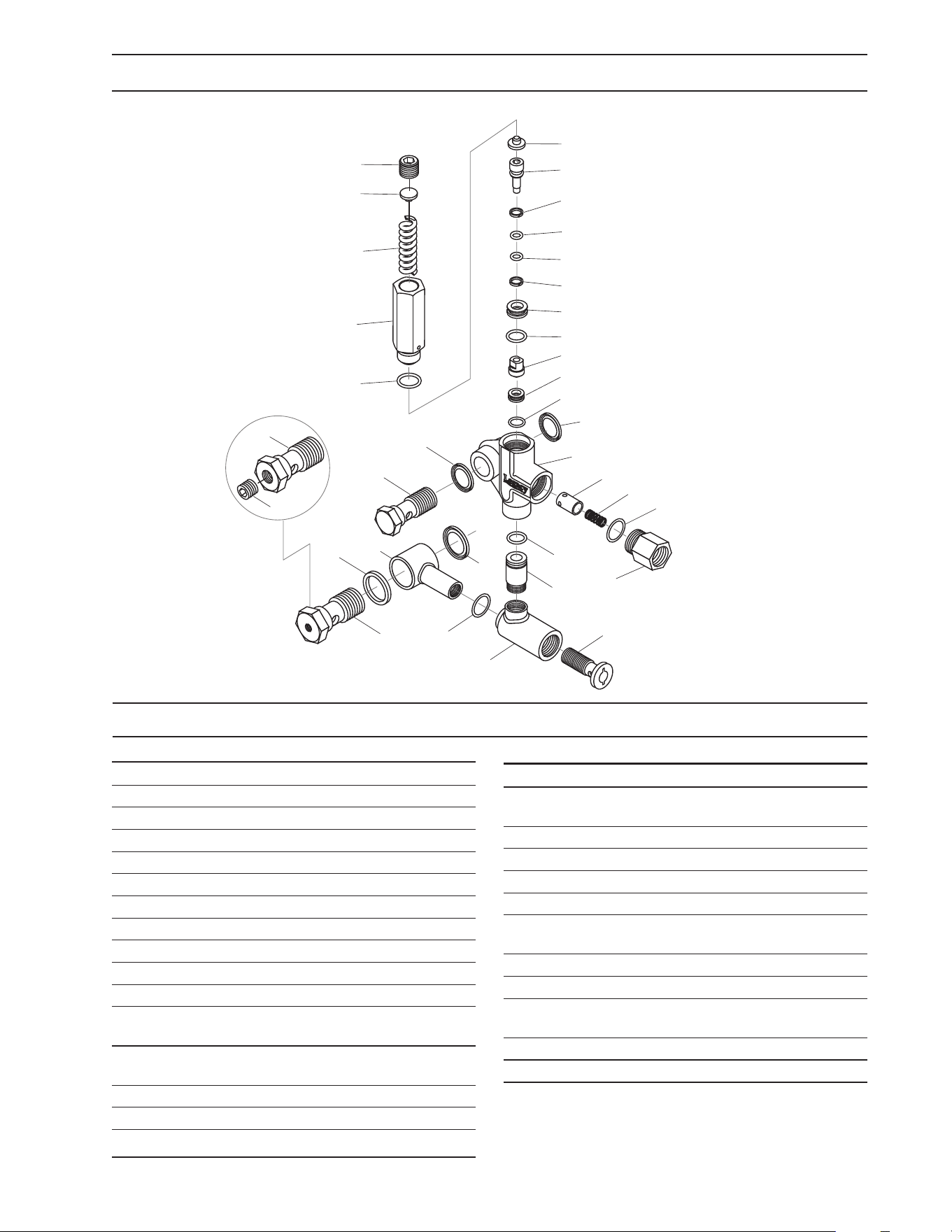
ITEM PART # DESCRIPTION KIT QTY
1* 8.754-929.0 Stem C 1
2* 9.803-912.0 Backup Ring A 1
3* 8.754-930.0 O-ring, Ø2.62 x 6.02 A 2
4 8.730-882.0 Stem Connector 1
5* 9.803-193.0 O-ring, Ø2.62 x 20.24 A 1
6* 9.803-908.0 Backup Ring A 1
7 9.803-907.0 Guide Bushing 1
8* 9.803-906.0 O-ring, Ø1.78 x 14 A 1
9* 8.754-959.0 Ball SubAssembly C 1
10* 8.754-933.0 Seat C 1
11* 8.754-934.0 O-ring, Ø1.78 x 12.42 A,C 1
12 8.754-935.0 Valve Body 1
13 9.802-893.0 Seal Washer 3/8 1
14 9.803-919.0 Banjo Bolt 3/8 1
15* 8.754-936.0 O-ring, Ø2.62 x 10.78 A 1
16 9.803-920.0 Banjo Bolt, 1/2, w/1/4" Port 1
VBT UNLOADER EXPLODED VIEW
VBT UNLOADER EXPLODED VIEW PARTS LIST
ITEM PART # DESCRIPTION KIT QTY
17 9.803-914.0 Seal Washer 1/2) 1
18 8.754-937.0 Bypass Manifold 1
19 9.802-892.0 Outlet Connector 3/8 MPT 1
20* 9.803-191.0 O-ring, Ø2.62 X 17.13 A,B 1
21* 8.933-017.0 Poppet Spring B 1
22* 8.754-939.0 Poppet B 1
23* 8.754-940.0 O-ring, Ø3 x 6 A,B 1
24* 8.754-961.0 Plate C 1
25* 8.933-018.0 Spring 1500-4000 PSI C 1
26 8.933-021.0 Set Screw 1
27 9.803-925.0 Nut 1
28 9.803-926.0 Knob, Brass, Unloader 1
* Included in Kit
Kit A 8.754-941.0 O-Ring Repair Kit
Kit B 8.754-942.0 Outlet Repair Kit
Kit C 8.754-957.0 Stem Repair Kit
8.754-696.0
UNLOADER, VBT BANJO 1/2M 3/8M, 3000PSI
Manual, Karcher • 9.807-623.0
23
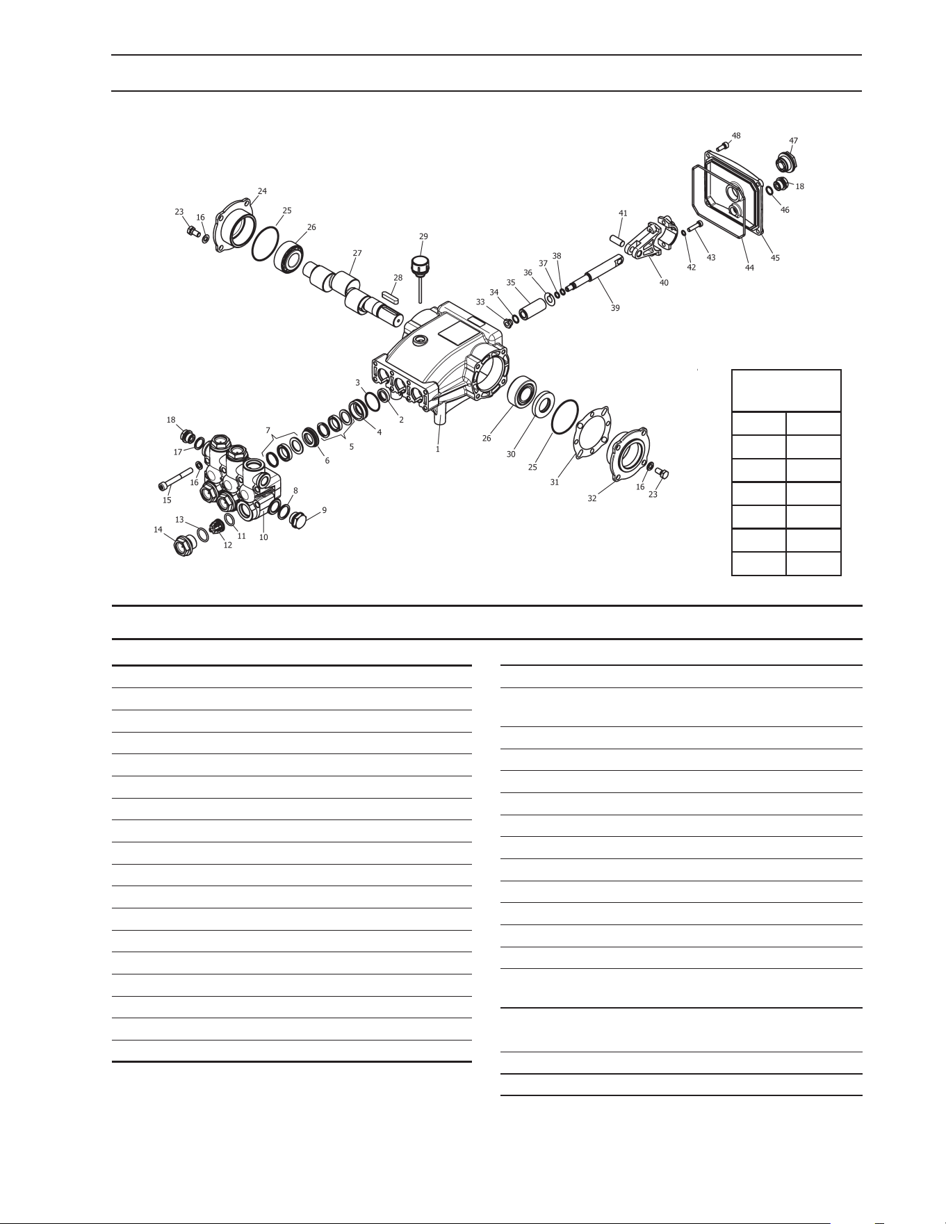
ITEM PART NO. DESCRIPTION QTY
1 8.751-216.0 Crankcase 1
2* See Kits Below Plunger Oil seal 3
3*
See Kits Below
O-Ring Ø1.78 x 31.47 3
4*
See Kits Below
Pressure Ring 3
5*
See Kits Below
U-Seal 3
6*
See Kits Below
Intermediate Ring 3
7*
See Kits Below
U-Seal 3
8 9.803-199.0 Washer, Copper 1
9
9.802-926.0 Plug, Brass 1/2
1
10 8.751-218.0 Manifold Head 1
11*
See Kits Below
O-Ring Ø2.62 x 17.13 6
12*
See Kits Below Valve Assembly
6
13*
See Kits Below
O-Ring Ø2.62 x 20.29 6
14 9.802-928.0 Valve Plug 6
15 9.802-938.0 Manifold Stud Bolt 8
16 9.802-884.0 Washer 16
17 9.803-198.0 Copper Washer 3/8 1
18 9.802-925.0 Brass Plug 3/8 2
ITEM PART NO. DESCRIPTION QTY
23 9.802-944.0 Hexagonal Screw 8
24 8.717-210.0 Closed Bearing
Housing 1
25 9.803-192.0 O-Ring Ø1.78 x 60.05 2
26 8.933-011.0 Tapered Roller Bearing 2
27 9.803-146.0 Crankshaft (3540) 1
9.803-147.0 Crankshaft
(4035)
1
28 9.803-167.0 Crankshaft Key 1
29 9.802-921.0 Oil Dip Stick 1
30 9.803-140.0 Crankshaft Seal 1
31 9.803-178.0 Shim 2
32 8.717-209.0 Bearing Housing 1
33*
See Kits Below
Plunger Nut, M8 3
34*
See Kits Below
Copper Spacer 3
35*
See Kits Below Plunger (4035) 3
Plunger (3540) 3
36*
See Kits Below
Copper Spacer 3
37*
See Kits Below
O-Ring Ring 3
38*
See Kits Below
Teon Ring 3
39
9.803-144.0 Plunger Rod
3
TORQUE
SPECS
Item # Ft.-lbs
14 75
15 30
23 8
33 9
43 13
48 7.6
8.751-189.0 KM4035R.3
8.751-186.0 KM3540R.3
8.933-149.0 KM3840R.3
KM.3 SERIES PUMP EXPLODED VIEW
KM.3 SERIES PUMP EXPLODED VIEW PARTS LIST

Manual, Karcher • 9.807-623.0
24
ITEM PART NO. DESCRIPTION QTY
40 9.803-158.0 Connecting Rod 3
41 8.751-228.0 Connecting Rod Pin 3
42 9.803-218.0 Spring Washer 6
43 9.803-238.0 Connecting Rod Screw 6
44 70-060009 O-Ring, Ø2.62 x 126.67 1
45 8.751-229.0 Crankcase Cover 1
46 9.803-197.0 O-Ring, Ø1.78 x 14 1
47 9.803-202.0 Sight Glass 3/4 1
48 9.802-939.0 Cover Screw 5
* Available in kit (See below)
REPAIR KIT NO. 8.725-360.0 8.725-358.0 8.725-361.0 8.725-359.0 8.725-237.0 8.933-023.0 9.802-603.0 9.802-609.0
KIT
DESCRIPTION
Plunger Seal
4035
18mm
Plunger Seal
3540
15mm
Complete Seal
Packing
4035
18mm
Complete Seal
Packing
3540
15mm
Plunger
4030
18mm
Plunger
3540
15mm
Complete
Valve
Plunger Oil
Seals
ITEM NUMBERS
INCLUDED
3, 5, 7 3, 5, 7 3, 4, 5, 6, 7 3, 4, 5, 6, 7
33, 34, 35, 36,
37, 38
33, 34, 35, 36,
37, 38
11, 12, 13 2
NO. OF CYLIN-
DERS KIT WILL
SERVICE
3 3 1 1 1 6 3
KM.3 SERIES PUMP EXPLODED VIEW PARTS LIST
Manual, Karcher • 9.807-623.0
25
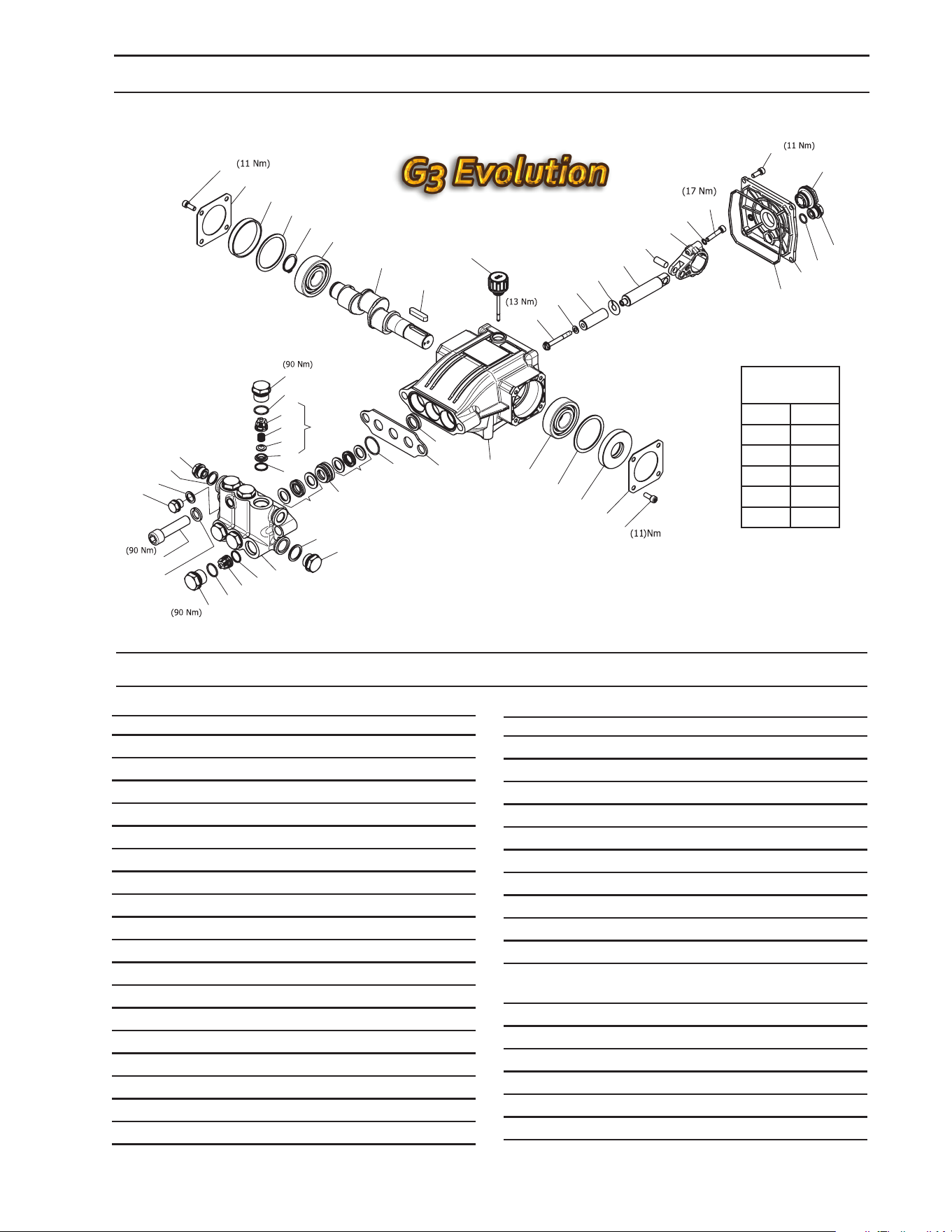
KBP3030R SERIES PUMP EXPLODED VIEW
KBP3030R SERIES PUMP EXPLODED VIEW PARTS LIST
8.929-255.0
ITEM PART NO. DESCRIPTION QTY
1 8.754-841.0 Crankcase 1
2* See Kits Below Plunger Oil Seal 1
3 8.758-216.0 Spacer 1
4* See Kits Below "O"-Ring Ø1.78 X 26.7 3
5* See Kits Below "U"-Seals 3
6* See Kits Below Pressure Ring 3
7* See Kits Below "U"-Seals 3
8 9.803-199.0 Washer, Copper G1/2 3
9 9.802-926.0 Plug, Brass G1/2 1
10* 8.759-028.0 Manifold 1
11* 8.717-233.0 O-ring Ø1.78 X 15.6 6
12* See Kits Below Valve Assembly 6
13 9.803-948.0 O-ring Ø1.78 X 18.77 6
14 9.803-949.0 Valve Plug 6
15* 8.754-850.0 Washer, Lock 1
16 8.929-349.0 Bolt Manifold M14x60 2
17 8.754-851.0 Plug Brass 1/4 1
18* 8.718-973.0 Washer cooper G1/4 2
19* 9.803-198.0 Washer, Copper G3/8 2
ITEM PART NO. DESCRIPTION QTY
20* 8.707-262.0 Plug, Brass G3/8 2
21* See Kits Below Valve Seat 6
22* See Kits Below Valve Plate 6
23 See Kits Below Valve Spring 6
24 See Kits Below Valve Cage 6
25 See Kits Below Screw, M6 X 16 12
26 8.717-137.0 Bearing Cover 2
27 9.803-954.0 Bearing Seal 1
28 8.754-843.0 Seal Spacer, Crankshaft 2
29 9.802-914.0 Snap Ring, 25 mm 1
30 9.803-955.0 Bearing, Ball 2
31 8.754-829.0 Shaft, 24 mm 3030 1
8.754-830.0 Shaft, 24 mm 4025 1
32 9.803-167.0 Key, Crankshaft 1
33 8.754-219.0 Oil Dipstick 1
34 8.933-010.0 Seal, Crankshaft 1
35* 8.754-855.0 Bolt, Plunger 3
36* 8.754-092.0 Spacer, Copper 3
37* 8.754-848.0 Plunger, 16 mm 3
25
26
27
28
29
30
31
32
33
35*
36*
37*
38*
39
40
41
42
43
44
45
25
26
34
28
30
1
3
4*
5*
6*
7*
8
9
10
11*
12*
13*
14*
21*
11*
14
20
19
18
17
16
15
13*
24*
23*
12*
22*
2*
46
20
47
25
TORQUE
SPECS
Item # Ft.-lbs
14 66
16 55
25 8
35 10
43 10
Manual, Karcher • 9.807-623.0
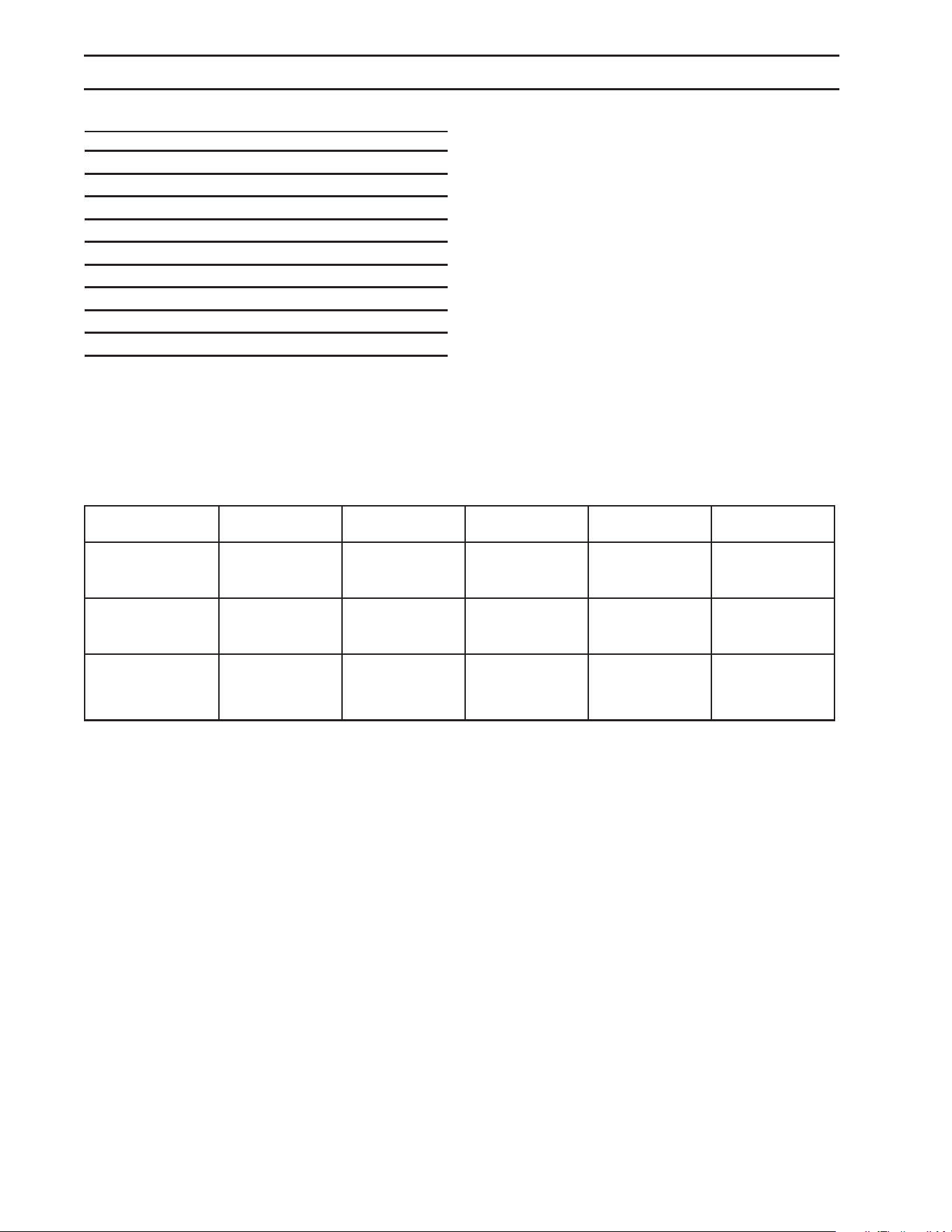
26
KBP3030R SERIES PUMP EXPLODED VIEW PARTS LIST
ITEM PART NO. DESCRIPTION QTY
38* 9.803-962.0 Spacer, Copper 3
39 8.754-827.0 Plunger Rod 3
40 9.803-965.0 Connecting Rod Pin 3
41 9.803-966.0 Connecting Rod 3
42 9.803-218.0 Washer, 6 mm 6
43 8.933-020.0 Screw, Connecting Rod 6
44 8.754-847.0 O-ring Ø2.62 X 111.62 1
45 8.754-842.0 Cover, Crankcase 1
46 9.803-906.0 O-ring Ø1.78 X 14 1
47 9.803-202.0 Sight Glass, G3/4 1
* Available in kit (See below)
REPAIR KIT
NUMBER
8.754-856.0 8.758-081.0 8.754-858.0 8.754-859.0 9.803-937.0
KIT
DESCRIPTION
Plunger Seal
16mm
Steel Packing
16mm
Pluger 16 mm Complete Valve
Plunger Oil
Seals
ITEM
NUMBERS
INCLUDED
4, 5, 7 4, 5, 6, 7 35, 36, 37, 38 11,12, 13 2
NUMBER OF
CYLINDERS
KIT WILL
SERVICE
3 1 1 6 3

Manual, Karcher • 9.807-623.0
27
advantages.
vielen Vorteilen.
avantages.
Registre su producto y aproveche de muchas ventajas.
Bewerten Sie Ihr Produkt und sagen Sie uns Ihre Meinung.
Rate your product and tell us your opinion.
Évaluer votre produit et dites-nous votre opinion.
Reseñe su producto y díganos su opinión.
www.kaercher.com/welcome
www.kaercher.com/dealersearch
Alfred Kärcher SE & Co. KG
Alfred-Kärcher-Str. 28-40
71364 Winnenden (Germany)
Tel.: +49 7195 14-0
Fax: +49 7195 14-2212
DANKE!
THANK YOU!
MERCI!
GRACIAS!
!