Powered by XPOWER
Low Grain Refrigerant
Dehumidier Owner's Manual
LGR Deshumidicador
Refrigerante de Grano Bajo
Manual de Usuario
LGR Déshumidicateur
Manuel d'Emploi
Model / Modelo / Modèle:
CD-90L, CD-130Li
(115V~, 60Hz)
Lea y guarde estas instrucciones
Lisez et gadez ces instructions
Read and save these instructions
Index: NA-1-A45
Edition: 2.1.Final
Powered by XPOWER
www.vikingairmovers.com | 1-(855)-855-8868

English - 2
Safety Instructions
WARNING - READ AND SAVE THESE INSTRUCTIONS BEFORE USING THIS
PRODUCT.
The user of electrical products may create hazards that include, but are not limited to
injury, fire, electrical shock. Failure to follow these instructions may damage and/or
impair its operation and void the warranty.
• Before operating, remove all packaging material and check for any damage that may
have occurred during shipping or any missing items.
• Check household power supply to ensure it matches the appliance’s specification.
• DO NOT operate the appliance with a damaged cord or plug. Discard or return to an
authorized service facility for examination and/or repair.
• Use only with GFCI protected receptacles. Contact a qualified electrician for verification
or installation of a GFCI receptacle if necessary.
• DO NOT run cord under carpeting. DO NOT cover cord with throw rugs, runners, or
similar coverings. DO NOT route cord under furniture or appliances. Arrange cord away
from traffic area and where it will not be tripped over.
• To reduce the risk of fire or electric shock, DO NOT use this appliance with any solid
state speed control device.
• DO NOT touch this appliance or the plug with wet hands or while standing in water.
• DO NOT operate the appliance near any pooled water.
• DO NOT use the product in areas where gasoline, paint or other flammable goods and
objects are used or stored.
• DO NOT insert or allow objects to enter any ventilation or exhaust opening as this may
damage the appliance and void the warranty.
• DO NOT cover the air inlet or outlet on the appliance.
• DO NOT direct the air flow at human faces or bodies.
• DO NOT allow children to play with this appliance.
• AUTOMATICALLY OPERATED DEVICE – To reduce the risk of injury, disconnect from
power supply before servicing.
• Remove the power cord from the electrical receptacle by grasping and pulling on the
power cord plug-end only, DO NOT pull the cord directly.
• DO NOT attempt to repair or adjust any electrical or mechanical functions of this
appliance, as this may cause danger and void the warranty.
• If the appliance is damaged or it malfunctions, DO NOT continue to use it. Unplug the
product from the electrical outlet. Refer to troubleshooting guide or contact Viking.
• Store in a dry area, away from exposure to sunlight, extreme temperature and humidity,
or other extreme environment, when not in use.
• DO NOT stack this appliance to more than three units.
• Always grip the trolley handle and keep the unit up when transporting from room to
room. DO NOT tilt the product on its side or upside down.
• If the dehumidifier was transported tilted on its side or upside down, you must position
it upright and wait at least 4 hours before using it again.
• An electronic instruction manual can be obtained through manufacturer’s website
www.vikingairmovers.com.
!
English - 3
• If the SUPPLY CORD is damaged, it MUST be replaced by the manufacturer, its service
agent or similarly qualified persons in order to avoid a hazard.
• This appliance is NOT intended for use by persons (including children) with reduced
physical, sensory or mental capabilities, or lack of experience and knowledge, unless
they have been given supervision or instruction concerning use of the appliance by a
person responsible for their safety. Children should be supervised to ensure that they
DO NOT play with the appliance.
• The appliance SHALL be installed in accordance with national wiring regulations.
• The dimensions of the space necessary for correct installation of the appliance
including the minimum permissible distances to adjacent structures.
WARNING:
• DO NOT use means to accelerate the defrosting process or to clean, other than those
recommended by the manufacturer.
• The appliance SHALL be stored in a room without continuously
operating ignition sources (for example: open flames, an operating
gas appliance or an operating electric heater.
• DO NOT pierce or burn.
• Be aware that refrigerants MAY NOT contain an odour.
Information for handling, installation, cleaning, servicing and disposal of refrigerant.
• Warning to keep any required ventilation openings clear of obstruction.
• Notice that servicing shall be performed only as recommended by the manufacturer.
• Warning that the non-FIXED APPLIANCE shall be stored in a room without continuously
operating open flames (for example an operating gas appliance) or other POTENTIAL
IGNITION SOURCES (for example an operating electric heater, hot surfaces).
(1) DD.3.3 Qualification of workers
(1.1) The manual shall contain specific information about the required qualification
of the working personnel for maintenance, service and repair operations. Every
working procedure that affects safety means shall only be carried out by competent
persons according to Annex HH.
(1.2) Examples for such working procedures are:
(1.2.1) Breaking into the refrigerating circuit
(1.2.2) Opening of sealed components;
(1.2.3) Opening of ventilated enclosures.
(2) DD.4 Information on servicing
(2.1) DD.4.1 General
(2.1.1) The manual shall contain specific information for service personnel
according to DD.4.2 to DD.4.10.
(2.2) DD.4.2 Checks to the area
(2.2.1) Prior to beginning work on systems containing FLAMMABLE
REFRIGERANTS, safety checks are necessary to ensure that the risk of

English - 4
(1.1.1) ignition is minimized. For repair to the REFRIGERATING SYSTEM.
(1.1) DD.4.3 Work procedure
(1.1.1) Work shall be undertaken under a controlled procedure so as to minimize
the risk of a flammable gas or vapor being present while the work is being
performed.
(1.2) DD.4.4 General work area
(1.2.1) All maintenance staff and others working in the local area shall be instructed
on the nature of work being carried out. Work in confined spaces shall be
avoided.
(1.3) DD.4.5 Checking for presence of refrigerant
(1.3.1) The area shall be checked with an appropriate refrigerant detector prior to
and during work, to ensure the technician is aware of potentially toxic or
flammable atmospheres. Ensure that the leak detection equipment being
used is suitable for use with all applicable refrigerants, i. e. non-sparking,
adequately sealed or intrinsically safe.
(1.4) DD.4.6 Presence of fire extinguisher
(1.4.1) If any hot work is to be conducted on the refrigerating equipment or any
associated parts, appropriate fire extinguishing equipment shall be available
to hand. Have a dry powder or CO2 fire extinguisher adjacent to the charging
area.
(1.5) DD.4.7 No ignition sources
(1.5.1) No person carrying out work in relation to a REFRIGERATING SYSTEM
which involves exposing any pipe work shall use any sources of ignition in
such a manner that it may lead to the risk of fire or explosion. All possible
ignition sources, including cigarette smoking, should be kept sufficiently far
away from the site of installation, repairing, removing and disposal, during
which refrigerant can possibly be released to the surrounding space. Prior to
work taking place, the area around the equipment is to be surveyed to make
sure that there are no flammable hazards or ignition risks. “No Smoking”
signs shall be displayed.
(1.6) DD.4.8 Ventilated area
(1.6.1) Ensure that the area is in the open or that it is adequately ventilated before
breaking into the system or conducting any hot work. A degree of ventilation
shall continue during the period that the work is carried out. The ventilation
should safely disperse any released refrigerant and preferably expel it
externally into the atmosphere.
(1.7) DD.4.9 Checks to the refrigerating equipment
(1.7.1) Where electrical components are being changed, they shall be fit for the
purpose and to the correct specification. At all times the manufacturer’s
maintenance and service guidelines shall be followed. If in doubt, consult
the manufacturer’s technical department for assistance.
(1.7.2) The following checks shall be applied to installations using FLAMMABLE
REFRIGERANTS:
– the actual REFRIGERANT CHARGE is in accordance with the room

English - 5
size within which the refrigerant containing parts are installed;
– the ventilation machinery and outlets are operating adequately and
are not obstructed;
– if an indirect refrigerating circuit is being used, the secondary circuit
shall be checked for the presence of refrigerant;
– marking to the equipment continues to be visible and legible.
Markings and signs that are illegible shall be corrected;
– refrigerating pipe or components are installed in a position where
they are unlikely to be exposed to any substance which may corrode
refrigerant containing components, unless the components are
constructed of materials which are inherently resistant to being corroded or are
suitably protected against being so corroded.
(1.8) DD.4.10 Checks to electrical devices
(1.8.1) Repair and maintenance to electrical components shall include initial safety
checks and component inspection procedures. If a fault exists that could
compromise safety, then no electrical supply shall be connected to the circuit
until it is satisfactorily dealt with. If the fault cannot be corrected immediately
but it is necessary to continue operation, an adequate temporary solution
shall be used. This shall be reported to the owner of the equipment so all
parties are advised.
(1.8.2) Initial safety checks shall include:
that capacitors are discharged: this shall be done in a safe manner to avoid
possibility of sparking;
that no live electrical components and wiring are exposed while charging,
recovering or purging the system;
that there is continuity of earth bonding.
(1) DD.5 Repairs to sealed components
(1.1) DD.5.1 During repairs to sealed components, all electrical supplies shall be
disconnected from the equipment being worked upon prior to any removal of
sealed covers, etc. If it is absolutely necessary to have an electrical supply to
equipment during servicing, then a permanently operating form of leak detection
shall be located at the most critical point to warn of a potentially hazardous
situation.
(1.2) DD.5.2 Particular attention shall be paid to the following to ensure that by working
on electrical components, the casing is not altered in such a way that the level
of protection is affected. This shall include damage to cables, excessive number
of connections, terminals not made to original specification, damage to seals,
incorrect fitting of glands, etc.
(1.2.1) Ensure that the apparatus is mounted securely.
(1.2.2) Ensure that seals or sealing materials have not degraded to the point that
they no longer serve the purpose of preventing the ingress of flammable
atmospheres. Replacement parts shall be in accordance with the
manufacturer’s specifications.

English - 6
(1) DD.6 Repair to intrinsically safe components
(1.1) Do not apply any permanent inductive or capacitance loads to the circuit without
ensuring that this will not exceed the permissible voltage and current permitted for
the equipment in use.
(1.2) Intrinsically safe components are the only types that can be worked on while live
in the presence of a flammable atmosphere. The test apparatus shall be at the
correct rating.
(1.3) Replace components only with parts specified by the manufacturer. Other parts
may result in the ignition of refrigerant in the atmosphere from a leak.
(1.4) NOTE The use of silicon sealant can inhibit the effectiveness of some types of leak
detection equipment. Intrinsically safe components do not have to be isolated prior
to working on them.
(2) DD.7 Cabling
(2.1) Check that cabling will not be subject to wear, corrosion, excessive pressure,
vibration, sharp edges or any other adverse environmental effects. The check shall
also take into account the effects of aging or continual vibration from sources such
as compressors or fans.
(3) DD.8 Detection of flammable refrigerants
(3.1) Under no circumstances shall potential sources of ignition be used in the searching
for or detection of refrigerant leaks. A halide torch (or any other detector using a
naked flame) shall not be used.
(3.2) The following leak detection methods are deemed acceptable for all refrigerant
systems.
(3.3) Electronic leak detectors may be used to detect refrigerant leaks but, in the case
of FLAMMABLE REFRIGERANTS, the sensitivity may not be adequate, or may
need re-calibration. (Detection equipment shall be calibrated in a refrigerant-free
area.) Ensure that the detector is not a potential source of ignition and is suitable
for the refrigerant used. Leak detection equipment shall be set at a percentage of
the LFL of the refrigerant and shall be calibrated to the refrigerant employed, and
the appropriate percentage of gas (25 % maximum) is confirmed.
(3.4) Leak detection fluids are also suitable for use with most refrigerants but the use of
detergents containing chlorine shall be avoided as the chlorine may react with the
refrigerant and corrode the copper pipe-work
(3.5) NOTE Examples of leak detection fluids are
(3.5.1) bubble method,
(3.5.2) fluorescent method agents
(3.6) If a leak is suspected, all naked flames shall be removed/extinguished.
(3.7) If a leakage of refrigerant is found which requires brazing, all of the refrigerant
shall be recovered from the system, or isolated (by means of shut off valves) in a
part of the system remote from the leak.

English - 7
(4) DD.9 Removal and evacuation
(4.1) When breaking into the refrigerant circuit to make repairs – or for any other
purpose – conventional procedures shall be used. However, for flammable
refrigerants it is important that best practice be followed, since flammability is a
consideration. The following procedure shall be adhered to:
a) safely remove refrigerant following local and national regulations;
b) purge the circuit with inert gas;
c) evacuate (optional for A2L);
d) purge with inert gas (optional for A2L);
e) open the circuit by cutting or brazing.
(4.2) The refrigerant charge shall be recovered into the correct recovery cylinders if
venting is not allowed by local and national codes. For appliances containing
flammable refrigerants, the system shall be purged with oxygen-free nitrogen to
render the appliance safe for flammable refrigerants. This process might need to
be repeated several times.
(4.3) Compressed air or oxygen shall not be used for purging refrigerant systems.
(4.4) For appliances containing flammable refrigerants, refrigerants purging shall
be achieved by breaking the vacuum in the system with oxygen-free nitrogen
and continuing to fill until the working pressure is achieved, then venting to
atmosphere, and finally pulling down to a vacuum (optional for A2L). This process
shall be repeated until no refrigerant is within the system (optional for A2L). When
the final oxygen-free nitrogen charge is used, the system shall be vented down to
atmospheric pressure to enable work to take place.
(4.5) Ensure that the outlet for the vacuum pump is not close to any potential ignition
sources and that ventilation is available.
(5) DD.10 Charging procedures
(5.1) In addition to conventional charging procedures, the following requirements shall
be followed.
(5.2) Ensure that contamination of different refrigerants does not occur when using
charging equipment.
(5.3) Hoses or lines shall be as short as possible to minimise the amount of refrigerant
contained in them.
(5.4) Cylinders shall be kept in an appropriate position according to the instructions.
(5.5) Ensure that the REFRIGERATING SYSTEM is earthed prior to charging the system
with refrigerant.
(5.6) Label the system when charging is complete (if not already).
(5.7) Extreme care shall be taken not to overfill the REFRIGERATING SYSTEM.
(5.8) Prior to recharging the system, it shall be pressure-tested with the appropriate
purging gas. The system hall be leak-tested on completion of charging but prior to
commissioning. A follow up leak test shall be carried out prior to leaving the site.
(6) DD.11 Decommissioning
(6.1) Before carrying out this procedure, it is essential that the technician is completely

English - 8
(1.1) familiar with the equipment and all its detail. It is recommended good practice that
all refrigerants are recovered safely.
(1.2) Prior to the task being carried out, an oil and refrigerant sample shall be taken in
case analysis is required prior to re-use of recovered refrigerant. It is essential that
electrical power is available before the task is commenced.
a) Become familiar with the equipment and its operation.
b) Isolate system electrically.
c) Before attempting the procedure, ensure that:
• mechanical handling equipment is available, if required, for handling
refrigerant cylinders;
• all personal protective equipment is available and being used correctly;
• the recovery process is supervised at all times by a competent person;
• recovery equipment and cylinders conform to the appropriate standards.
d) Pump down refrigerant system, if possible.
e) If a vacuum is not possible, make a manifold so that refrigerant can be
removed from various parts of the system.
f) Make sure that cylinder is situated on the scales before recovery takes place.
g) Start the recovery machine and operate in accordance with instructions.
h) Do not overfill cylinders (no more than 80 % volume liquid charge).
i) Do not exceed the maximum working pressure of the cylinder, even
temporarily.
j) When the cylinders have been filled correctly and the process completed,
make sure that the cylinders and the equipment are removed from site promptly
and all isolation valves on the equipment are closed off.
k) Recovered refrigerant shall not be charged into another REFRIGERATING
SYSTEM unless it has been cleaned and checked.
(1) DD.12 Labeling
(1.1) Equipment shall be labeled stating that it has been decommissioned and emptied
of refrigerant. The label shall be dated and signed. For appliances containing
FLAMMABLE REFRIGERANTS, ensure that there are labels on the equipment
stating the equipment contains FLAMMABLE REFRIGERANT.
(2) DD.13 Recovery
(2.1) When removing refrigerant from a system, either for servicing or decommissioning,
it is recommended good practice that all refrigerants are removed safely.
(2.2) When transferring refrigerant into cylinders, ensure that only appropriate
refrigerant recovery cylinders are employed. Ensure that the correct number of
cylinders for holding the total system charge is available. All cylinders to be used
are designated for the recovered refrigerant and labeled for that refrigerant (i. e.
special cylinders for the recovery of refrigerant). Cylinders shall be complete with
pressure-relief valve and associated shut-off valves in good working order. Empty
recovery cylinders are evacuated and, if possible, cooled before recovery occurs.

English - 9
(2.3) The recovery equipment shall be in good working order with a set of instructions
concerning the equipment that is at hand and shall be suitable for the recovery
of all appropriate refrigerants including, when applicable, FLAMMABLE
REFRIGERANTS. In addition, a set of calibrated weighing scales shall be available
and in good working order. Hoses shall be complete with leak-free disconnect
couplings and in good condition. Before using the recovery machine, check that
it is in satisfactory working order, has been properly maintained and that any
associated electrical components are sealed to prevent ignition in the event of a
refrigerant release. Consult manufacturer if in doubt.
(2.4) The recovered refrigerant shall be returned to the refrigerant supplier in the correct
recovery cylinder, and the relevant waste transfer note arranged. Do not mix
refrigerants in recovery units and especially not in cylinders.
(2.5) If compressors or compressor oils are to be removed, ensure that they have
been evacuated to an acceptable level to make certain that FLAMMABLE
REFRIGERANT does not remain within the lubricant. The evacuation process
shall be carried out prior to returning the compressor to the suppliers. Only electric
heating to the compressor body shall be employed to accelerate this process.
When oil is drained from a system, it shall be carried out safely.
(2.6) When installing this equipment, the minimum allowable distance from adjacent
structures should be guaranteed to be 10cm.
Information for qualication of workers
• All operators or refrigeration system maintenance personnel shall have a valid
certificate issued by an industry-recognized evaluation body to certify that they are
qualified for the safe disposal of refrigerant agents as recognized by the industry;
• Maintain and repair the equipment only in accordance with the method recommended
by the equipment manufacturer. If other professionals are required to assist in the
maintenance and repair of equipment, do so under the supervision of personnel
qualified to use combustible refrigerants.

English - 10
Class Name Classification of instructions
Personnel Qualification
Requirements
A Professional
Maintenance
Personnel
Personnel, such as
installers and maintenance
supervisors, who are required
to install, repair, and weld
the refrigeration system for
flammable refrigerant products
Hold A class A certificate
issued by the competent
authority, available
online.
B Regular
contacts
personnel
1. Personnel who do not need
to open the refrigeration system
of combustible refrigerant
products, such as relevant
personnel of transportation
enterprises and general
maintenance personnel of
product after-sales department,
etc
2. Installation and maintenance
personnel of conventional
refrigerant products
Hold a Class B certificate
issued by the competent
authority, available
online.
C
(The
enterprise
internal)
Develop,
design
and test
personnel
Combustible refrigerant system
design personnel, supervision
personnel
1. Master the skills and
knowledge of basic
safety welding and
safety protection level of
combustible refrigerant:
2. Familiar with product
development process
and capable of design:
3. Qualification
certification/recognition
shall be conducted by
the institution where you
work
(1) Personnel with class A certificate can carry out the operation of class B personnel;
(2) Class A and Class B personnel shall be trained and certified by the industry
management institution designated by the state;
(3) C type personnel should participate in the company’s internal organization of
professional training, obtain internal issued certification or accreditation qualifications.

English - 11
Tooling Names Use Requirement
Small Vacuum
Pump
Explosion-proof vacuum pump: ensure a certain accuracy, vacuum
degree should be less than 10Pa.
Filling
Equipment
Special explosion-proof charging equipment: with certain accuracy,
the charging amount deviation is less than 5g.
Leak Detector Regular calibration: annual leakage rate is not higher than 10g.
Concentration
Detector
A) The maintenance site shall be equipped with A fixed combustible
refrigerant concentration detector, which shall be connected to the
safety protection alarm system: its error must be guaranteed not to
be higher than 5%.
B) The installation site shall be equipped with portable combustible
refrigerant concentration detector, which can realize two-level
acoustic-optic alarm: its error must be guaranteed not to be higher
than 10%.
C) Regular calibration.
D) Function check and confirmation shall be carried out before use.
Pressure
Gauge
A) The pressure gauge shall be calibrated regularly
B)R290 and R161 refrigerant can use the pressure gauge of R22,
R32 refrigerant can use the pressure gauge of R410A.
Fire
Extinguisher
Carry a fire extinguisher during installation and maintenance.
There should be at least two kinds of dry powder, carbon dioxide
and foam extinguishers in the maintenance site, and they should
be placed in the prescribed position with eye-catching signs and
accessible places.
(1) The installation site should be in a well-ventilated condition.
(2) The sites for installing and maintaining an air conditioner using Refrigerant R32
should be free from open fire or welding smoking, drying oven or any other heat
source higher than 548
℃
which easily produces open fire.
(3) When installing an air conditioner, it is necessary to take appropriate anti-static
measures such as wear anti-static clothing and or gloves.
(4) It is necessary to choose the site convenient for installation or maintenance wherein
the air inlets and outlets of the indoor and outdoor units should be not surrounded by
obstacles or close to any heat source or combustible and/or explosive environment.
(5) lf the indoor unit suffers refrigerant leak during the installation, all the personnel
should go out till the refrigerant leaks completely for 15 minutes. lf the product is
damaged, it is a must to carry such damaged product back to the maintenance station
and it is prohibited to weld the refrigerant pipe or conduct other operations on the
user’s site.

English - 12
Handling of Refrigerants
The handling, installation, storage, servicing and disposal must comply with the
provisions of gas-related national laws and regulations, and also national wiring
regulation.
It is necessary to clear away the refrigerant in the system when maintaining or scrapping
an appliance.
Ventilated Area (Open Doors and Windows)
Ensure that the working area is open or well ventilated before turning on the system
or performing hot work. Ventilation should be maintained during operation. Ventilation
quickly displaces safely diluted leaked refrigerant into the atmosphere.
Flammable refrigerant R32 is used within appliance. Please follow the instructions
carefully to handle, install, clean, and service the appliance to avoid damage or hazard.
Do not dispose of appliance in regular trash. Contact qualified agency for proper
disposal.
Servicing shall be performed only as recommended by the manufacturer.
(1) lt is necessary to choose the place where the inlet and outlet air of the indoor unit is
even.
(2) lt is necessary to avoid the places where there are other electrical products, power
switch plugs and sockets, kitchen cabinet, bed, sofa and other valuables right under
the lines on two sides of the indoor unit, and also prevent mechanical damage from
occurring.
English - 13
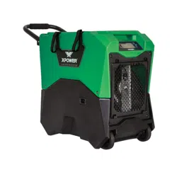
Commercial Dehumidier Introduction
• XPOWER Commercial Dehumidifiers are designed to maximize water extraction while
combining the highest efficiency in performance and portability.
• Latest technology and a high efficiency extraction process ensures peak performance
in even the most challenging environments, such as extreme temperatures and low
humidity environments.
• With a high and efficient water removal capacity, the Dehumidifier allows an extreme
dry zone in the working area and water migration to the air from all surfaces. It is ideal
for water damage restoration and industrial applications where maximum air drying
performance is needed.
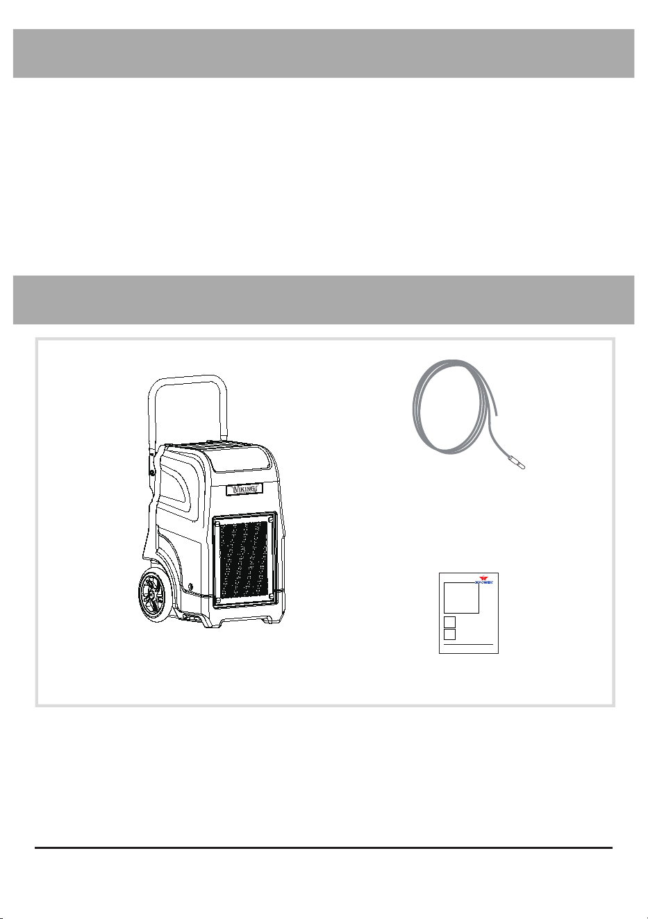
Items Included
Powered by XPOWER
Dehumidier Owner's Manual
Model:
XD-75L, XD-85L
(115V 60HZ)
Read and save these instructions before use
www.xpower.com | 1-(855)-855-8868 | [email protected]
Index: NA-1-A1
Edition: 1.1.Alpha
Dehumidifier x 1
Drain Hose x 1
Owner’s Manual x 1
English - 14
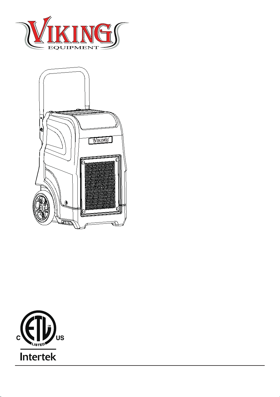
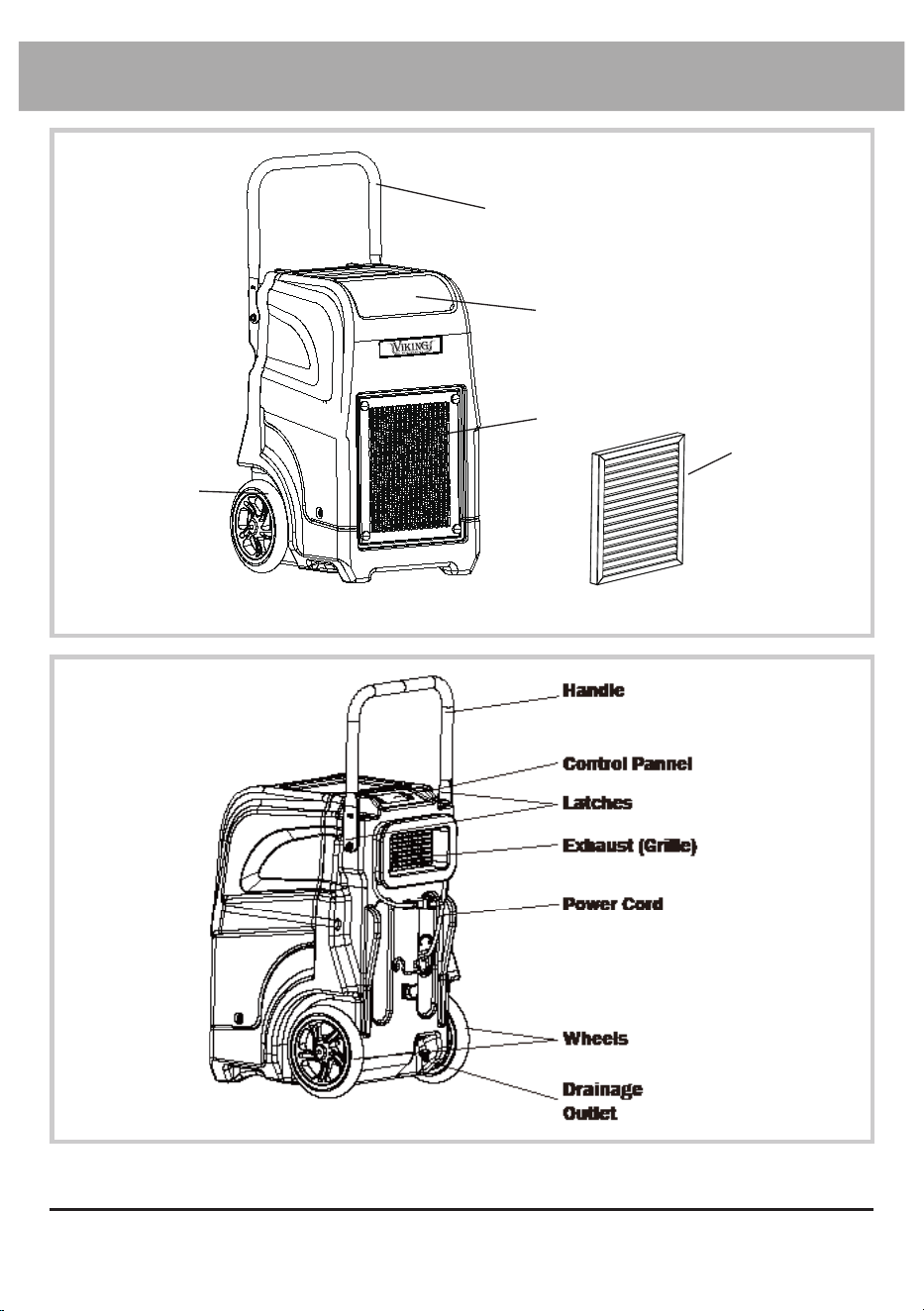
Parts Description
Handle
Compartment
Filter
Intake
(Grille)
Wheels
Powered by XPOWER
FRONT
REAR

English - 15
• Positioning: Before using the dehumidifier, place the unit UPRIGHT for at least 1
hour before use to allow the refrigerant to stabilize. If the unit was tilted on its side or
upside-down during transportation, set the unit UPRIGHT for at least 4 hours before
use. The dehumidifier must be positioned UPRIGHT on a level surface during use.
• Enclosed Area: For optimal efficiency, the dehumidifier must be operated in an
enclosed area. Keep all doors, windows and other outside entrances to the room
closed. Turn off the air conditioning.
• Air Circulation: It’s suggested to have a constant efficient air circulation inside the
area that you are going to work in, for example, setting up a circulation with XPOWER
Air Mover combinations.
• Power Cord and Drain Hose: The power cord has a length of 9.0 feet (2.75 meters)
and the drain hose has a length of 40.0 feet (12.0 meters). Select a location where
the power cord can reach the power source and the drain hose can reach the area
you want. Please do not lift the drainage hose higher than 16 feet (5.0 m) above the
machine.
• Inlet and Outlet Orientation: Also pay attention to the orientation of the air inlet and
air outlet. Make sure the airflow won’t influence any object near the dehumidifier.
• IMPORTANT: The effectiveness of the dehumidifier can be influenced by different
factors. You should keep any new moisture-laden air away from the working area and
allow sufficient enclosed air circulation in the room. You may also find that installing
multiple dehumidifiers may be required for larger enclosed areas.
Selecting a Location (Important)
Installation and Operation Guide
English - 16
Control Panel
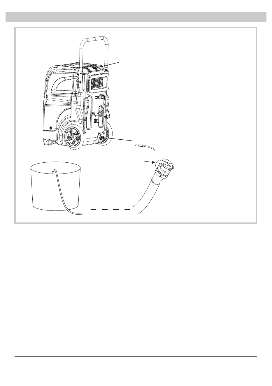
Drain Hose
Drain Hose Installation
• Attach the drain hose
inlet to the drain outlet
of the machine.
• The machine’s outlet
can be found as the
graph on the left.
• Please have a separate
container to collect the
water coming from the
other end of the drain
hose.
Press to
Install/Release
English - 17
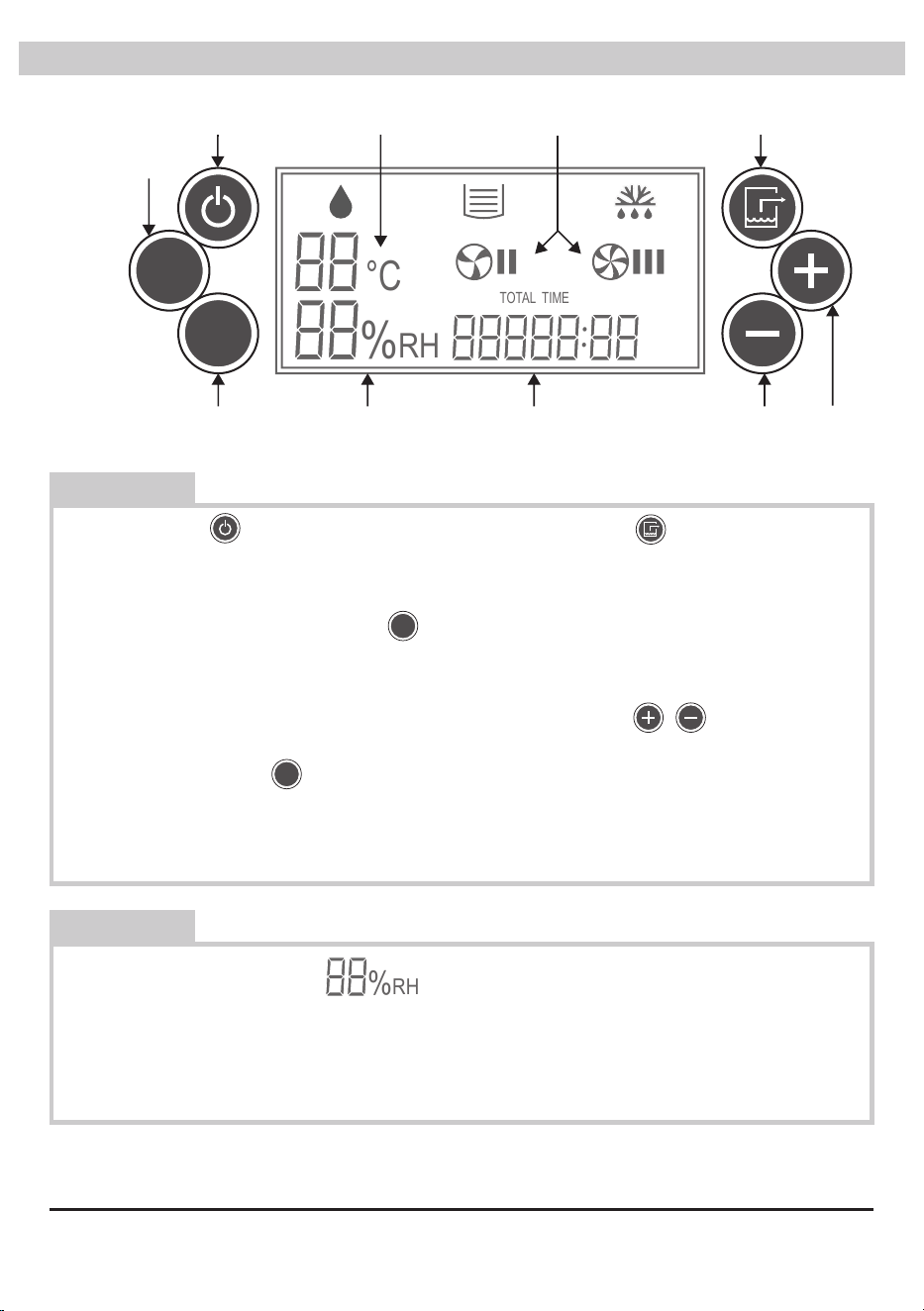
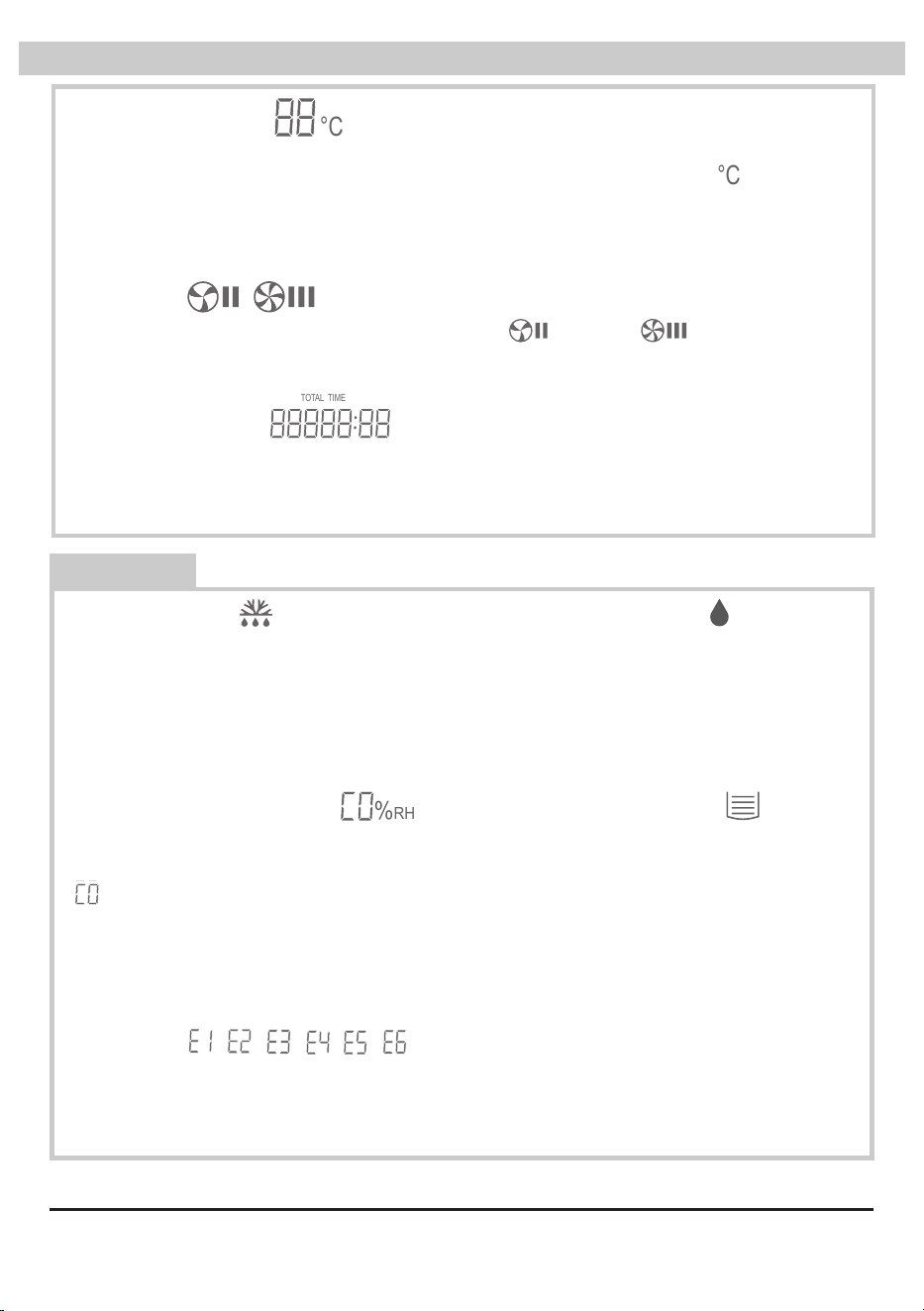
Relative Humidity Display
This will show the relative humidity level of the setting or environment. By default, it
displays the actual environmental humidity. When adjusting humidity, it will display
the setting humidity and blink. After 5 seconds from the last adjustment, it will
display the environmental humidity again. (See Page 7: Humidity Control)
CT
F/C
:
°C
%RH
TOTAL TIME
Control Panel
CT
F/C
:
°C
%
RH
TOTAL TIME
Temperature DisplayPower Control
Evaporator
Coil/
Environment
Temperature
Switch
Fahrenheit/Celsius
Scale Switch
Relative Humidity
Display
Total Running Time
Humidity Control
Fan Speed Manual Drainage
Power Control
Press to switch the dehumidifier ON or
OFF.
CT
F/C
:
°C
%
RH
TOTAL TIME
Fahrenheit/Celsius Scale Switch
Press to switch the display of the
temperature in Fahrenheit or Celsius
scale.
CT
F/C
:
°C
%
RH
TOTAL TIME
Manual Drainage
Press to drain manually. Manual drain will
last for 45 seconds. [See Page 9: Drainage
(Important)]
CT
F/C
:
°C
%
RH
TOTAL TIME
Humidity Control
Tap “+”/“-” to increase/decrease the
desired humidity level by 1% increments.
Touch and hold to increase/decrease the
setting humidity level by 5% per second.
The adjustable range is 30% to 90%.
CT
F/C
:
°C
%
RH
TOTAL TIME
CT
F/C
:
°C
%
RH
TOTAL TIME
Evaporator Coil/Environmental
Temperature Switch
Press to switch the display of the
temperature of the evaporator coil or
environment.
CT
F/C
:
°C
%
RH
TOTAL TIME
Buttons
Information
English - 18
Temperature Display
This will show the temperature of the evaporator or environment (See Page 7:
Evaporator Coil/Environmental Temperature Switch). When in Celsius scale, will
be illuminated. When in Fahrenheit scale, will turn off. If the temperature shown
is higher than 99°F, the scale will be set to Celsius automatically (See Page 7:
Fahrenheit/Celsius Scale Switch).
CT
F/C
:
°C
%RH
TOTAL TIME
CT
F/C
:
°C
%RH
TOTAL TIME
Control Panel (Continued)
Drainage Indicator Light
When this light blinks, it indicates the
machine is in drainage process. When
this light stays bright, it indicates the
water tank is full.
CT
F/C
:
°C
%
RH
TOTAL TIME
Constant Dehumidication
At the humidity level setting of 30%, if
humidity control button “-” is pressed,
:
°C
%RH
TOTAL TIME
will blink on the humidity display.
The machine will enter into constant
dehumidification mode and won’t stop
dehumidification as environmental
humidity changes.
:
°C
%RH
TOTAL TIME
Error Codes , , , , ,
These are error codes. Please refer
to Troubleshooting Guide for more
information.
Fan Speed
This will show if the machine is running on low ( ) or high ( ) fan speed. The
dehumidifier will control the fan speed according to the environmental temperature
and humidity.
CT
F/C
:
°C
%
RH
TOTAL TIME
CT
F/C
:
°C
%
RH
TOTAL TIME
CT
F/C
:
°C
%
RH
TOTAL TIME
CT
F/C
:
°C
%
RH
TOTAL TIME
Total Running Time
This will show the total running time from the first usage to the current moment.
Running time starts to count during the time when the machine turns on. The value
can’t be reset.
CT
F/C
:
°C
%RH
TOTAL TIME
Defrosting Light
This light indicates the evaporator coil
or environmental temperature is too
low. Frost may start to appear on the
evaporator coil. The machine is now
defrosting.
CT
F/C
:
°C
%
RH
TOTAL TIME
Dehumidication Light
When this light blinks, it indicates
the machine is now preparing for
dehumidification. When this light stays
bright, it indicates the machine is now
dehumidifying.
CT
F/C
:
°C
%
RH
TOTAL TIME
Indicators
:
°C
%
RH
TOTAL TIME
:
°C
%
RH
TOTAL TIME
:
°C
%
RH
TOTAL TIME
:
°C
%
RH
TOTAL TIME
:
°C
%
RH
TOTAL TIME
:
°C
%
RH
TOTAL TIME

English - 19
Start Your Job
Turn on the dehumidifier
Press the Power Control button to switch on the machine. You may see the
dehumidification light is flashing. Please wait for 3 minutes (180 seconds) until the
machine completes the startup.
Write down the starting time
Please remember to write down the starting time right after the machine
starts, if you want to calculate the usage time.
Set the desired humidity level
• Tap the humidity control button to adjust the setting humidity level. The default
humidity setting is 30%. The adjustable range is from 30% to 90% (See Page 7:
Humidity Control). The machine will try to match the set humidity level and maintain it.
• If you want the machine to work constantly, please adjust the humidity level down
to 30%, and then press “-” (See Page 8: Constant Dehumidification). Tap “+” to exit
constant dehumidification mode.
• If the dehumidifier loses power accidentally, when turned on again, the dehumidifier
will work on the last known configuration.
Dehumidification
• When the machine is dehumidifying, the dehumidification light goes on.
• You may see the dehumidification light is flashing. That means the dehumidification
temporally pauses or the environmental humidity has reached the setting level. Please
wait until the machine completes the startup or until the humidity level rises up again.
• The dehumidifier will control the fan speed according to the environmental temperature
and humidity.
Defrosting
• When the evaporator coil or the environmental temperature is too low, frost may
appear on the evaporator. This will lower the effectiveness of the dehumidification. The
machine will start defrosting until the temperature goes back to normal.
• When the machine is defrosting, the dehumidification pauses. The dehumidification
light goes off, and the defrosting light will go on.
• Do not turn off the machine during defrosting process.
Drainage (Important)
• Press the Manual Drainage button to manually drain the unit. It will last for 45 seconds
and won’t stop dehumidification or defrosting process.
• If the water tank is full or not positioned horizontally, the water tank full indicator light
will go on. Any dehumidification or defrosting process will pause and the machine will
automatically process drainage for 45 seconds. Afterwards, if the water tank is still
CT
F/C
:
°C
%RH
TOTAL TIME
English - 20
Start Your Job (Continued)
• When turned off, the machine will automatically process drainage for 60 seconds.
Please wait until this process completes.
• Please do not lift the drainage hose higher than 16 feet (5 m) above the machine.
Calculate the usage time
• Please remember to write down the ending time right before the machine
shuts down.
• Compare the starting time and the ending time to calculate the usage time.
Turn off the dehumidifier
Press the Power Control button to switch off the machine. When turned off, the machine
will automatically process drainage for 60 seconds. Please wait until this process
completes.
CT
F/C
:
°C
%
RH
TOTAL TIME
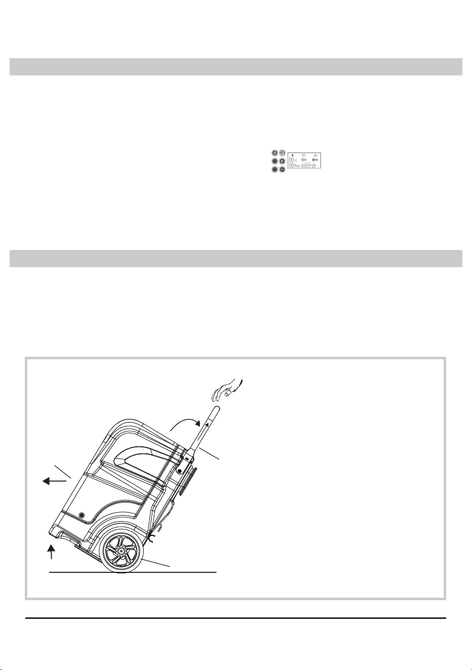
Transportation
Before transportation, you should always:
• Press the Manual Drainage Button to manually drain the unit. Otherwise the water may
spill and enter into core parts of the machine during transportation. This may also void
the warranty.
• Disconnect the machine from the power source.
• Remove all the extension setup and uninstall the power cord and drain hose.
Wheels
Handle
Intake
Transport with Handle
Lift the dehumidifier on the
wheels and push to transport with
the Telescoping Handle.
detected to be full, an error code will be displayed (See Page 8: Error Codes or Page
13: Troubleshooting Guide).
English - 21
User Maintenance Instructions
Frequent maintenance is recommended on this appliance. Failure to follow the
maintenance instructions may cause failure of the appliance and void the warranty.
Before maintenance or storage, you should always:
• Process a drainage manually.
• Disconnect the machine from the power source.
• Remove all the extension setup.
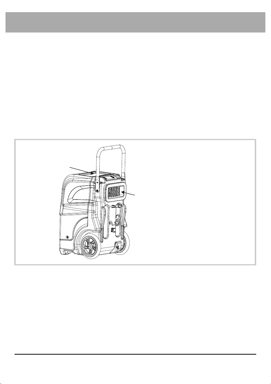
Exhaust
Compartment
Organize the Power Cord
and Drain Hose
• Remove the drain hose
from the outlet of the
machine.
• Store the power cord
and the drain hose in the
compartment.
Store the machine
• Store the appliance in a dry and cool indoor place, away from direct sunlight as well as
chemicals and out of reach of children.
• IMPORTANT: make sure the machine is positioned on a level surface.
• If you want to stack this appliance, stack them on their tops with the same orientation.
• Do not stack more than three units of this appliance.
Clean the surface
• Use a damp cloth to wipe the surface of the housing. Do not clean the unit with water
directly.
• Do not clean the fins of the evaporator and condenser by yourself.
English - 22
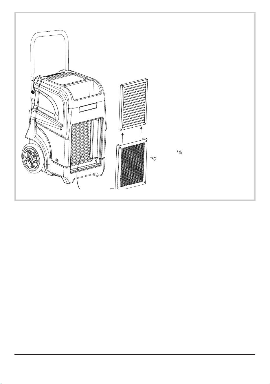
①
②
③
Store or Replace
the Filters
①
Unscrew the four
screws.
②
Take out filter
grille.
③
Slide off the filter
from the grille.
• Clean and wash
the filters with
water.
• Store the filter
in dry and cool
area in a sealed
container.
• Replace filters if
necessary.
English - 23
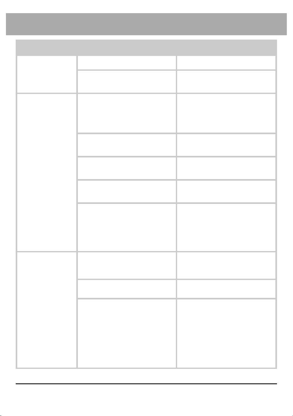
Troubleshooting Guide
PROBLEM POSSIBLE CAUSE SOLUTION
Dehumidifier
does not start
No electricity. Check for power supply.
The power cord is not properly
plugged in.
Remove and reconnect the
power cord.
Dehumidifier
runs but humidity
level does not
decrease
The dehumidification system is
within startup process.
Wait for 3 minutes
(180 seconds) until the
dehumidification light stops
blinking.
The humidity level setting is
too high.
Decrease the humidity level
setting.
The working area is not
enclosed.
Make sure the area is tightly
sealed.
There are other sources of
humidity in the room.
Remove these sources or wait
until they completely volatilize.
The humidity level has reached
the setting level.
Decrease the humidity level
setting, set to constant
dehumidification mode, wait
until the humidity level rises up
again.
Dehumidifier runs
but humidity level
does not decrease
The machine was tilted and
wasn’t positioned upright for
enough time before use.
Position the machine upright on
a level surface and wait for at
least 4 hours before next use.
The air filter or air inlet/outlet is
blocked.
Remove blockage.
The environmental temperature
is too low/high or the humidity
level is too low.
The dehumidifier is designed to
work in an environment with a
temperature of 33.0 °F to 105.0
°F (0.6 °C to 40.6 °C) and
relative humidity level of 20%
and higher. Make sure the room
temperature/humidity does not
exceed this range.

English - 24
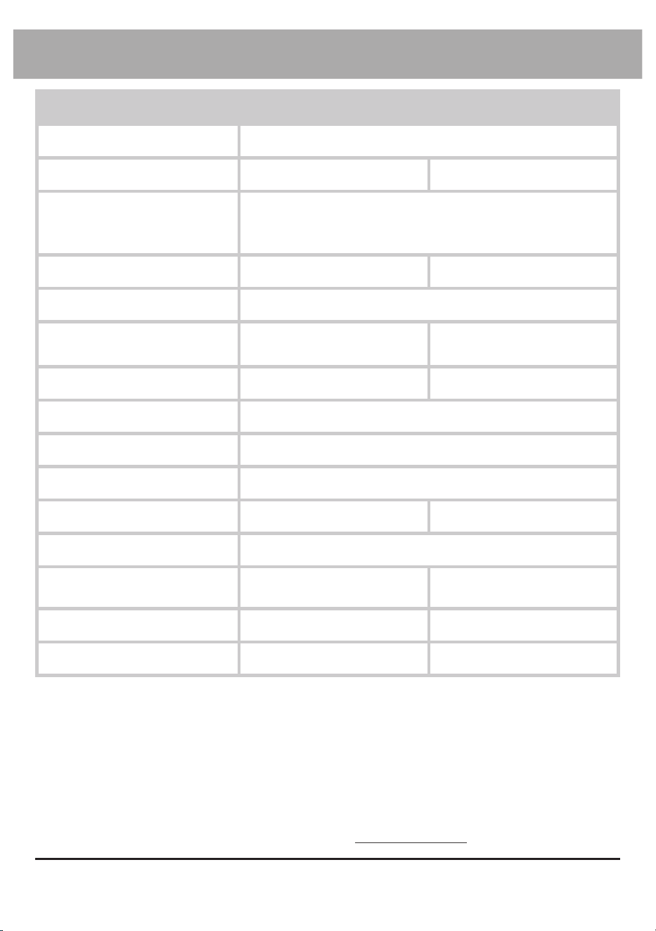
PROBLEM POSSIBLE CAUSE SOLUTION
Water on the floor The drain hose is loose. Tighten the connection of the
drain hose.
Sudden noise The machine starts drainage
process.
The water pump can create
sounds during operation. This is
a normal sound.
Error Code: E2 Failure of the temperature
sensor.
The dehumidification can
function but you won’t be able
to see the temperature/humidity
on the screen. Contact XPOWER
for more assistance.
Error Code: E3 Failure of the humidity sensor.
Error Code: E4 Failure of the water pump Contact XPOWER for more
assistance.
The machine is not in a level
position.
Position the machine on a level
surface.
The drain hose is blocked. Remove blockage.
Error Code: E5 Failure of the defrost sensor. The dehumidification can
function but will defrost for 5
minutes every half an hour.
Contact XPOWER for more
assistance.
If troubleshooting does not resolve your problem, please contact XPOWER or other
parties authorized by XPOWER for further instructions.
English - 25
Technical Specication
MODEL NUMBER CD-90L CD-130Li
Voltage / Frequency 115 V~, 60 Hz
Amperage 5.8 A 8.2 A
Operation Temperature/
Relative Humidity
Requirement
33.0 °F - 105.0 °F (0.6 °C to 40.6 °C) /
20% RH or higher
Rated Airflow 180 CFM N/A
Speed Control Automatic
Water Removal Efficiency
80 °F (26.7 °C) / 60% RH
85 Pints (40 L)/day 125 Pints (59 L)/day
Refrigerant R32 / 300 g R32 /480 g
Compartment Feature Yes
Time Meter Up to 9,999 hours 50 minutes
Filter Type Stainless Steel Filter
Cord Length 9.0 ft. / 2.75 m 10.0 ft. / 3.0 m
Drain Hose Length 40 ft. / 12.0 m
Unit Dimension (L) x (W) x (H)
16.0 x 17.9 x 34.4 in. /
40.9 x 45.5 x 87.5 cm
21.9 x 20.6 x 34.5 in. /
55.6 x 52.2 x 87.7 cm
Unit Weight 75.6 lbs. / 34.3 kg 89.7 lbs. / 40.7 kg
Safety Certification ETL/C-ETL N/A
If your product(s) is not listed above, please visit www.xpower.com for more information.

English - 26
1 YEAR LIMITED WARRANTY
Viking-branded products purchased in the U.S. from authorized distributors include
a 1-year limited warranty. Contact Viking to confirm warranty information about your
product(s).
This limited warranty covers defects in materials and workmanship in your Viking-
branded products, purchased in the U.S. ONLY. Local warranty policy (if any) in your
country will cover products purchased outside the U.S.
Viking Limited Warranty (USA)
Items mentioned but not limited to below are not covered by warranty:
(1) Power cord, filters or any other components considered as a “consumable parts” by
Viking.
(2) Normal wear and tear.
(3) Problems that result, directly or indirectly, at Viking’s sole discretion, from:
(3.1) External causes such as accident, abuse, misuse or problems with electrical power
supply.
(3.2) Disassembling, servicing or modification not authorized by Viking.
(3.3) Usage that is not accordant with product instructions stated in Owner’s Manual.
(3.4) Failure to follow the product instructions or lack of necessary maintenance stated
in Owner’s Manual.
Before contacting Viking, please try one or more of the following:
(1) Consult this Owner’s Manual and follow the instructions of troubleshooting guide.
(2) Access www.vikingairmovers.com for more advice and information that could be
helpful to address your problems.
If you need additional assistance from Viking, please:
(2) Call Viking U.S. Customer Service Department at 855-855-8868 or other numbers
provided on www.vikingairmovers.com.
(3) Visit Viking U.S. Head Office at 668 S. 6th Ave., City of Industry, CA 91746 or the most
current address provided on www.vikingairmovers.com.
Please also have your original proof of purchase and the serial number(s) of your
product(s) ready when you contact Viking.
IMPORTANT:
(1) Please finish the online warranty registration before usage. Visit www.vikingairmovers.
com/service-support/warranty-registration.
(2) This Limited Warranty applies with its own timeliness. Contact Viking or visit
www.vikingairmovers.com for more information.

English - 27

Read and save these instructions
Lea y guarde estas instrucciones
Lisez et épargnez ces instructions
Index: NA-1-A45
Edition: 2.1.Final
Powered by XPOWER
www.vikingairmovers.com | 1-(855)-855-8868 |
info@xpower.com
VIKING Equipment Co., Inc.
668 S. 6th Ave.,
City of Industry, CA 91746 USA