MILWAUKEE TOOL
l
www.milwaukeetool.com
13135 W. Lisbon Road, Brookeld, WI 53005
Drwg. 1
56
---------------
Handle Housing - Support (1)
57 23-66-0193 Toggle (1)
58
---------------
Trigger Spring (1)
59 44-60-0213 Rivet Pin (1)
60 40-50-0373 Two Action Lever Spring (1)
61 23-66-0182 Lock-Out Trigger (1)
70 10-22-1008 Warning Label (1)
71 12-20-0358 Service Nameplate (1)
82 16-01-0207 Rotor Assembly (1)
84 31-44-0368 Housing Service Kit (1)
85 28-14-0072 Gearcase Support Service Assembly (1)
86 28-14-0069 Gearcase Cover Service Assembly (1)
89 14-20-0312 Electronics Service Kit (1)
91 31-92-0126 Lock-O Trigger Service Kit (1)
10 11 12
13 14 15
16 17
85
18 19 20
21 22 24
25 26
86
23 48 49
50 51 56
70 71
84
26
25
24
19
18
17
14
13
12
9
7
7
11
10
8
(2x)
6
5
3
(3x)
2
4(3x)
1(3x)
21
20
16
15
26
(4x)
23
(2x)
27
28
50
51
(2x)
48
49
(16x)
59
60
58
57
56
55
61
71
70
22
29
10
11
82
57 58 59
60 61
91
1 2 3
5 7 55
89
to
S
h
aft
(
o
n
pg
.
2)
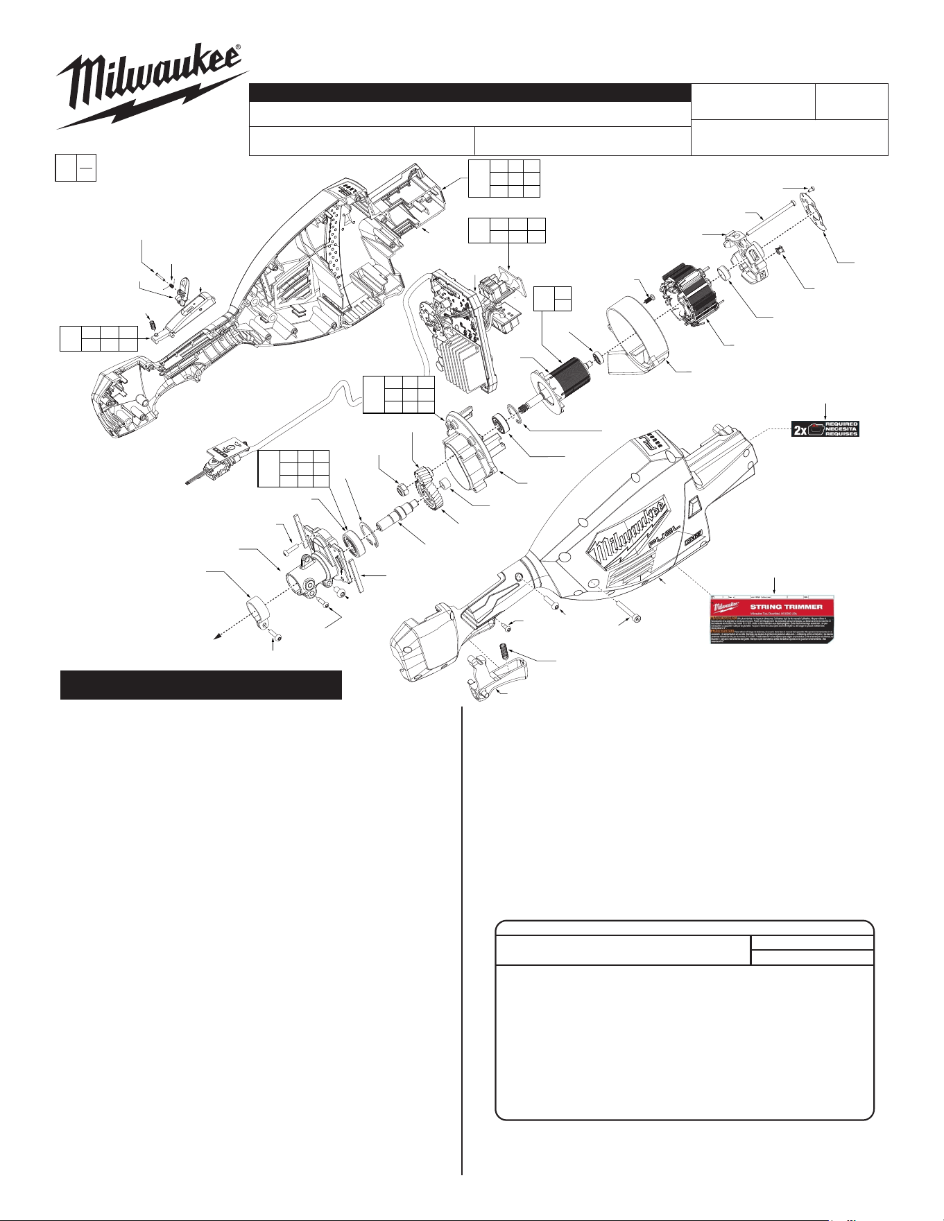
EXAMPLE:
Component Parts (Small #)
Are Included When Ordering
The Assembly (Large #).
0
00
FIG. PART NO. DESCRIPTION OF PART NO. REQ.
1 05-74-0144 M3 x 5mm T-10 Torx Screw (3)
2
---------------
Hall Board (1)
3
---------------
Isolator (3)
4 05-74-0516 M4 x 67mm Pan Hd. T-20 Torx Screw (3)
5
---------------
Motor End Cap (1)
6 22-32-0102 Rubber Cap (1)
7
---------------
Stator (1)
8 06-82-0161 M4 x 10mm T-20 Torx Screw (2)
9 42-46-0012 Motor Bae Cage (1)
10 02-04-0163 Ball Bearings (1)
11
---------------
Rotor (1)
12
---------------
Retaining Ring (1)
13 02-04-0164 Ball Bearing (1)
14 28-14-0019 Gearcase Support (1)
15 32-60-0022 Helical Pinion (1)
16 05-55-0025 Hex Nut (1)
17 02-04-0013 Needle Bearing (1)
18 32-05-0037 Helical Gear (1)
19 45-08-0047 Helix Gear Shaft (1)
20
---------------
Retaining Ring (1)
21
---------------
Ball Bearings (1)
22 42-82-0016 Gearcase Tube Coupler (1)
23 43-87-0042 Dumping Bar (2)
24 05-74-0339 M8 x 13mm PH Torx T-30 Screw (1)
25 05-78-0033 M5 x 20mm Screw (3)
26 05-74-0202 M4 x 16mm PH T-20 Torx Screw (5)
27 40-50-0374 Trigger Spring (1)
28 23-66-0173 Trigger Cap (1)
29 22-38-0111 Tube Clamp (1)
48
---------------
Handle Housing - Cover (1)
49 05-88-1200 M4 x 16mm PH T-20 Torx Screw (16)
50 05-71-0017 M4 x 10mm PH T-20 Torx Screw (1)
51 05-75-0019 M5 x 37mm CH Hex Recess Screw (2)
55
---------------
PCBA (1)
FIG. PART NO. DESCRIPTION OF PART NO. REQ.
SCREW TORQUE SPECIFICATIONS
SEAT TORQUE
FIG. PART NO. WHERE USED (kgf-cm) (lb-in)
1 05-74-0144 Gear Case 2 2
4 05-74-0516 Gear Case 22±2 19±2
8 06-82-0161 Motor Bae Cage 10±1 9±1
16 05-55-0025 Gear Case 100±8 87±7
24 05-74-0339 Gear Case 42±2 36±2
25 05-78-0033 Gear Case 60±2 52±2
26 05-74-0202 Tube Clamp/Gear Case 22±2 19±2
49 05-88-1200 Handle Housing - Cover 18±2 16±2
50 05-71-0017 Handle Housing - Cover 10±1 9±1
51 05-75-0019 Handle Housing - Cover 42±2 36±2
SERVICE PARTS EXPLODED VIEW
BULLETIN NO.
54-49-3015
SERVICE PARTS LIST
CATALOG NO. 3006-20
REVISED BULLETIN
SPECIFY CATALOG NO. AND SERIAL NO. WHEN ORDERING PARTS
M18 FUEL
™
Dual Battery String Trimmer
SERIAL NO.
DATE
Feb. 2024
WIRING INSTRUCTION
N46A
See Page 4
43a
43b
43c
43d
43e
43g
42
39
37a
(2x)
35
33
(2x)
36
34
30
32
38
47
44
(4x)
40
41
(4x)
45
(2x)
46
31
44 45
46 47
80
25 63
64 65
88
34 36
39
92
67
(2x)
62
66
37 66
67
81
25
(2x)
65
73
76
75
74
37b
(2x)
64
(2x)
63
30
32
90
31
73
87
43a 43b
43c 43d
43e 43g
43
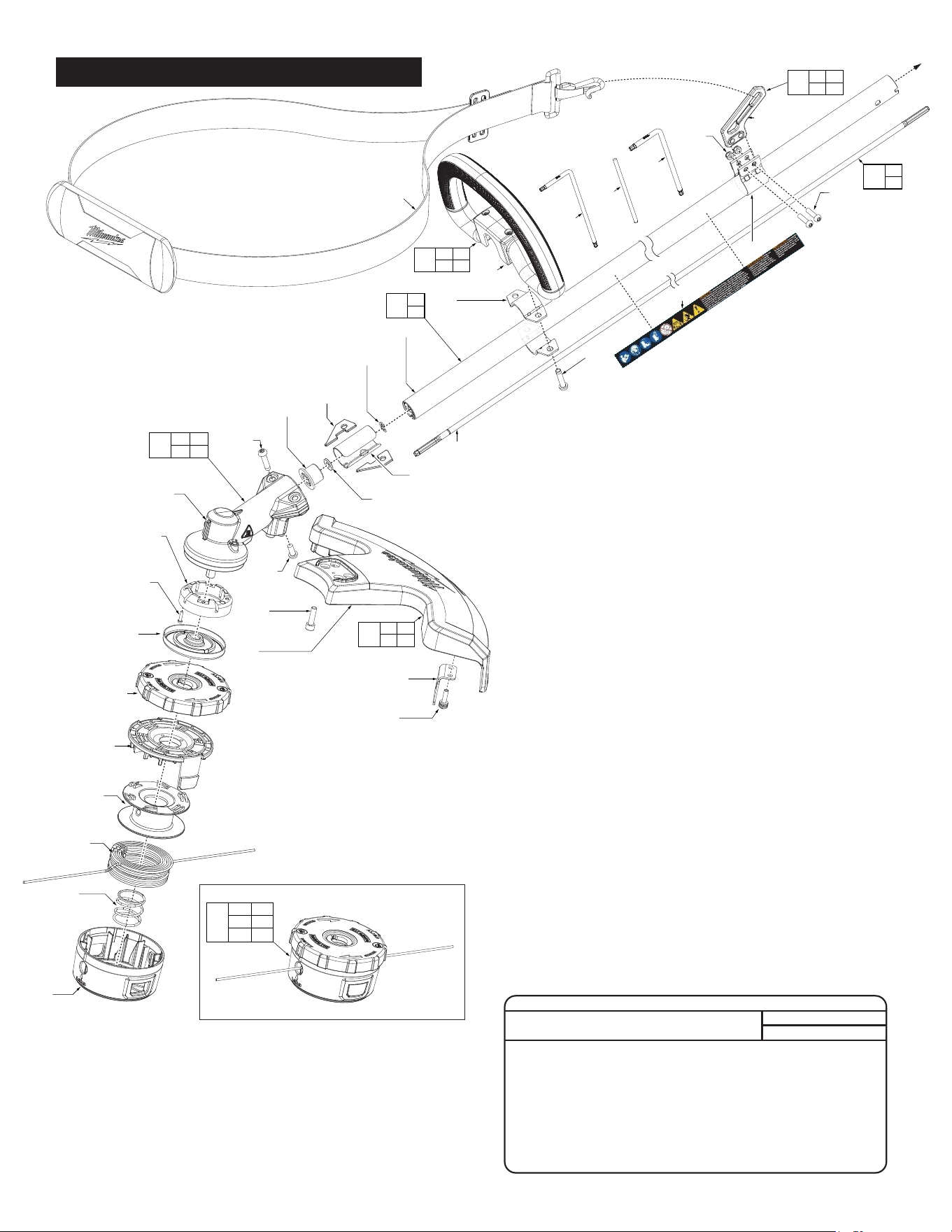
Easy Load Trimmer Head Assy.
FIG. PART NO. DESCRIPTION OF PART NO. REQ.
25 05-78-0033 M5 x 20mm Screw (3)
30
---------------
Spline Drive Shaft (1)
31
---------------
Aluminum Tube (1)
32 30-40-0022 E-Ring (1)
33 43-44-0121 Sealing Gasket (2)
34 31-86-0021 Spacer Sleeve (1)
35 45-88-0463 Washer (1)
36 43-72-0088 Washer Holder (1)
37 05-74-0242 M6 x 25mm PH Torx T-30 Screw (4)
38 05-81-0132 M6 x 14mm PH Torx T-30 Screw (1)
39
---------------
Bevel Gearcase Assembly (1)
40 42-87-0029 Counterweight (1)
41 05-74-0501 M3 x 12mm PH Torx T-10 Screw (4)
42 44-66-0129 Lock Plate Assembly (1)
43 49-16-2748 Easy Load Trimmer Head Assy. (1)
43a
---------------
Housing Plate (1)
43b
---------------
Trimmer Head Ring (1)
43c
---------------
Spool (1)
43d
---------------
.080" Red String (25ft.) (1)
43e 40-50-0296 Trimmer Head Spring (1)
43g 42-30-0051 Trimmer Head Housing Assembly (1)
44 05-88-0135 M6 x 1 CH Torx T-30 Screw (4)
45 05-74-0344 M5 x 20mm PH Torx Screw (2)
46 42-26-0032 Cutting Blade (1)
47 28-14-0049 17" Trimmer Guard (1)
62 43-74-0116 Shoulder Strap/Hook (1)
63 43-74-0118 Shark Fin Hook (1)
64 05-55-0157 M5 Nylon Insert Nut (2)
65 45-58-0056 Shoulder Strap Mounting (1)
66 31-44-0408 Bail Handle (1)
67 42-68-0292 Handle Clamp Plate (2)
73 10-22-0050 Warning Label (1)
74 43-96-0016 T-25 Torx Key (1)
75
---------------
Straight Tool (1)
76 49-96-0026 T-30 Torx Key (1)
80 43-54-0014 String Guard Service Kit (1)
81 31-44-0366 Carrier Handle Service Kit (1)
87 42-92-0176 Aluminum Tube Service Kit (1)
88 45-66-0042 Shoulder Strap Bracket Service Kit (1)
90 45-08-0095 Drive Shaft Service Kit (1)
92 32-05-0033 Bevel Gearcase Service Assembly (1)
SCREW TORQUE SPECIFICATIONS
SEAT TORQUE
FIG. PART NO. WHERE USED (kgf-cm) (lb-in)
25 05-78-0033 Shoulder Strap Mount 60±2 52±2
37a 05-74-0242 Bevel Gear Case Assy. 42±2 36±2
37b 05-74-0242 Carrier Handle 27±2 23±2
38 05-81-0132 Bevel Gear Case Assy. 42±2 36±2
41 05-74-0501 Bevel Gear Case Assy. 10±1 9±1
43 49-16-2748 Easy Load Trimmer Hd 150±5 130±4
44 05-88-0135 Trimmer Guard 30±2 26±2
45 05-74-0344 Cutting Blade 30±2 26±2
SERVICE PARTS EXPLODED VIEW (continued)
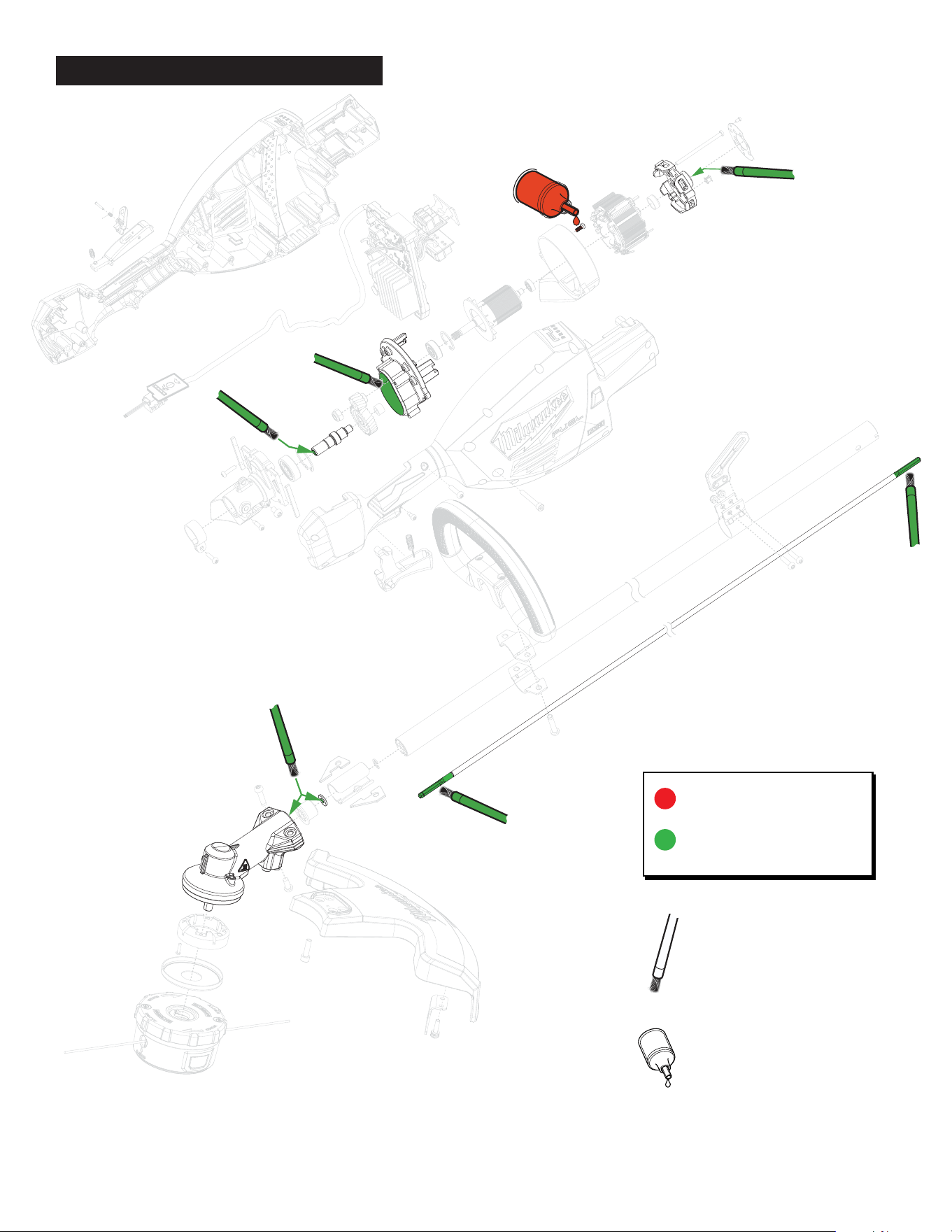
277 Red Loctite
®
,
No. 44-22-0050
Type “J” Grease (1-lb. can),
No. 49-08-4220
NOTE
Regarding parts to be lubricated:
Apply a light coating of grease to
all highlighted parts shown prior
to installation. Reference the key
above for grease types.
:
NOTE
Regarding parts to receive
thread locking sealant: Place one
to two drops of the recommended
Loctite® thread locking sealant
(or the equivelant) to the threads
of parts shown prior to
installation.
Apply grease to
female spline within
gearcase assembly.
LUBRICATION INSTRUCTIONS
1
1
1
2
2
2
3
2
3
2
1
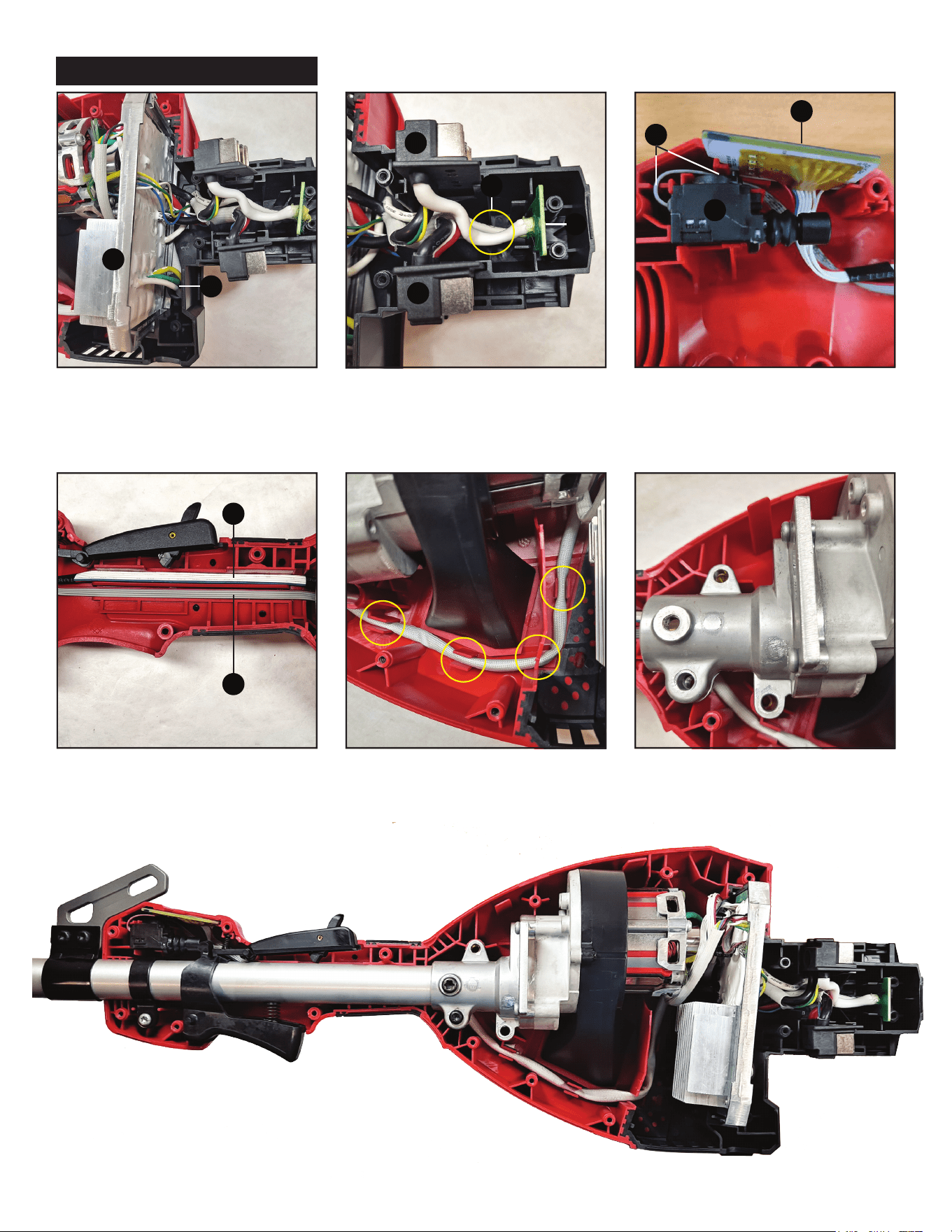
Be sure all components and wires are properly seated
before replacing the housing cover with screws.
Use extra caution
when installing
electronic
components
to avoid damage.
UI board wire (1) and switch wire (2) need to
be pressed into channels as shown.
Press braided white wire into slots as shown. Make sure gearcase fits properly into slots and
screw holes align.
PCBA Frame (1) should be inserted into slots
as shown, with motor wire (2) routed through
bottom of the PCBA.
Insert thick white wires (1), terminal blocks (2),
and fuse tracer (3) into slots as shown.
Insert switch (1), switch wire (2), and hall board
(3) into slots as shown.
WIRE ROUTING