
VIVOTEK
2 - User's Manual
Table of Contents
Read Before Use ..................................................................................................................................... 3
Overview.......................................................................................................................................................4
Revision History ......................................................................................................................................4
Package Contents ...................................................................................................................................5
Symbols and Statements in this Document .............................................................................................5
Physical Description
...............................................................................................
7
Hardware Installation ...........................................................................................................10
Network Deployment .............................................................................................................................23
Software Installation ..............................................................................................................................26
Ready to Use .........................................................................................................................................29
Accessing the Network Camera .................................................................................................................30
Using Web Browsers ............................................................................................................................. 30
Using RTSP Players .............................................................................................................................. 33
Using 3GPP-compatible Mobile Devices ...............................................................................................34
Using VIVOTEK Recording Software ....................................................................................................35
Main Page ..................................................................................................................................................36
Client Settings ............................................................................................................................................44
Conguration ..............................................................................................................................................49
System > General settings ....................................................................................................................50
System > Homepage layout .................................................................................................................51
System > Logs ......................................................................................................................................54
System > Parameters ........................................................................................................................... 55
System > Maintenance .......................................................................................................................... 56
Media > Image ....................................................................................................................................60
Media > Video .......................................................................................................................................71
Media > Audio........................................................................................................................................78
Network > General settings ...................................................................................................................80
Network > Streaming protocols ...........................................................................................................87
Network > DDNS .................................................................................................................................93
Network > SNMP (Simple Network Management Protocol) ..................................................................98
Network > FTP ......................................................................................................................................99
Security > User accounts ....................................................................................................................100
Security > HTTPS (Hypertext Transfer Protocol over SSL) ......................................................102
Security > Access List .......................................................................................................................109
PTZ > PTZ settings ............................................................................................................................ 114
Event > Event settings ........................................................................................................................123
Applications > Motion detection...........................................................................................................138
Applications > DI and DO ..................................................................................................................141
Applications > Tampering detection ....................................................................................................142
Applications > Audio detection ..........................................................................................................143

VIVOTEK
User's Manual - 3
Applications > VADP (VIVOTEK Application Development Platform) ............................................................... 145
Recording > Recording settings ........................................................................................................................ 148
Local storage > SD card management ............................................................................................................... 153
Local storage > Content management ............................................................................................................... 154
Appendix ................................................................................................................................................................. 157
URL Commands for the Network Camera .......................................................................................................... 157
Technical Specications ..................................................................................................................................... 343
Technology License Notice ................................................................................................................................. 346
Electromagnetic Compatibility (EMC) ................................................................................................................. 347
Read Before Use
The use of surveillance devices may be prohibited by law in your country. The Network Camera is not
only a high-performance web-ready camera but can also be part of a exible surveillance system. It is
the user’s responsibility to ensure that the operation of such devices is legal before installing this unit for
its intended use.
It is important to rst verify that all contents received are complete according to the Package Contents
listed below. Take note of the warnings in the Quick Installation Guide before the Network Camera is
installed; then carefully read and follow the instructions in the Installation chapter to avoid damage due to
faulty assembly and installation. This also ensures the product is used properly as intended.
The Network Camera is a network device and its use should be straightforward for those who have basic
networking knowledge. It is designed for various applications including video sharing, general security/
surveillance, etc. The Configuration chapter suggests ways to best utilize the Network Camera and
ensure proper operations. For creative and professional developers, the URL Commands of the Network
Camera section serves as a helpful reference to customizing existing homepages or integrating with the
current web server.

VIVOTEK
4 - User's Manual
Overview
The SD9363 and SD9364 is a speed dome camera specically designed to enhance low light
surveillance in large coverage areas. Equipped with 150 M IR illuminators and a 30x optical
zoom lens, the camera provides a superb low light image in the most challenging situations. The
camera also adopts VIVOTEK's latest IR technology, VAIR (Vari-Angle IR). VIVOTEK's VAIR
provides smooth vari-angle adjustment of the IR illuminators that adapts to broad coverage FOV
when zoomed out and a highly uniform IR intensity to reach out to a far distance when zoomed
in, while avoiding hot-spots traditionally associated with IR illumination.
The camera is the rst PTZ surveillance camera with IR Illumination to utilize H.265 compression
technology. When combined with VIVOTEK's Smart Stream II technology users can obtain
bandwidth savings of up to 80% compared to traditional H.264. By combining 1080p full HD
resolution with H.265, IR illuminators, VAIR, WDR, and 30x optical zoom, the camera is able to
capture ne details at top-notch quality, 24 hours a day, 7 days a week. The camera is protected
by an IP66- and NEMA 4X-rated housing against rain, dust, and corrosion. The camera has a
wide operating temperature range from -50°C to 55°C, ensuring continuous operation under the
most extreme weather conditions and hazardous environments. This makes the camera ideally
suited to monitor wide open spaces such as ports, highways, cities, and parking lots where high-
level precision is required.
VIVOTEK further strengthened the camera performance with an IP66- and NEMA 4X-rated
housing to protect the camera against rain, dust, and corrosion. The SD9364-EHL-v2 has a
wide operating temperature range from -40°C to 55°C, ensuring continuous operation under
the most extreme weather conditions and hazardous environments. This makes the SD9364-
EHL-v2 ideally suited to monitor wide open spaces such as ports, highways, cities, and parking
lots where high-level precision is required.
Revision History
■ Rev. 1.0: Initial release
VIVOTEK
User's Manual - 5
Package Contents
■ SD9363-EHL-v2, SD9364-EH-v2, or SD9364-EHL-v2
■ Wall Mount Bracket / Screws and anchors
■ Screws / Alignment Sticker / T20 and T25 L-wrench
■ Safety tether anchor and screws, an RJ45 connector
■ Quick Installation Guide
■ IO Combo Cable (may come with one 1m combo cable or Separately Purchased)
Symbols and Statements in this Document
i
INFORMATION: provides important messages or advices that might help prevent inconvenient
or problem situations.
NOTE: Notices provide guidance or advices that are related to the functional integrity of the
machine.
Tips: Tips are useful information that helps enhance or facilitae an installation, function, or
process.
WARNING: or IMPORTANT:: These statements indicate situations that can be dangerous or
hazardous to the machine or you.
Electrical Hazard: This statement appears when high voltage electrical hazards might occur
to an operator.
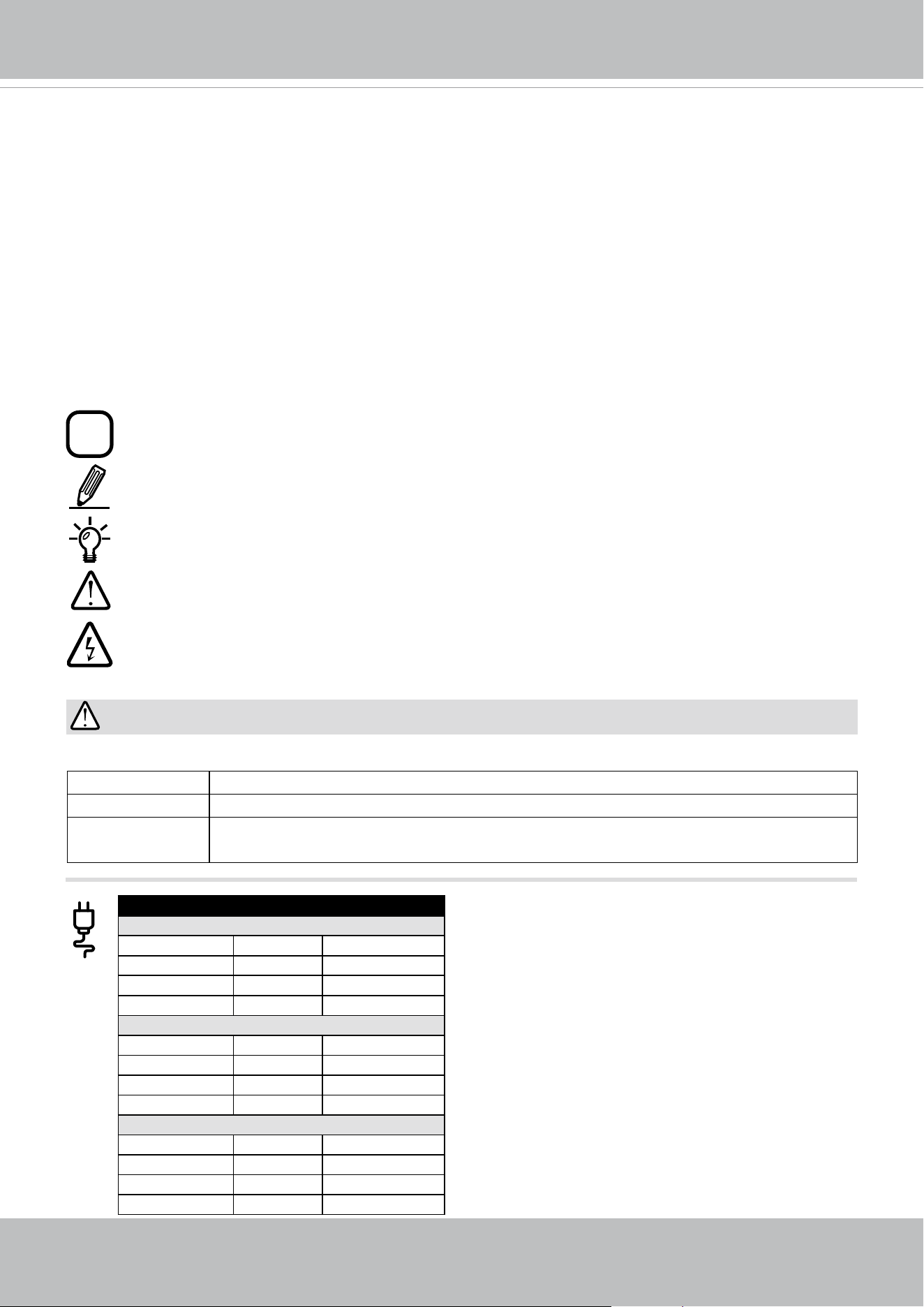
IMPORTANT:
Below are the requirements for powering the the speed dome:
Power source Power Consumption
DC 24V Max. 63W (heater and fan on); Max. 35W (heater and fan off)
High power PoE Max. 70W (heater and fan on); Max. 40W (heater and fan off), using
VIVOTEK's AP-GIC-010A-095 & AW-IHH-0100 & AW-IHH-0200
Heater ON/OFF IR ON/OFF Consumption
PoH / PoE (95W)
ON ON 70W
ON OFF 59W
OFF ON 51W
OFF OFF 40W
AC 24V
ON ON 96W
ON OFF 81.5W
OFF ON 70W
OFF OFF 55.5W
DC 24V
ON ON 63W
ON OFF 53W
OFF ON 45W
OFF OFF 35W
VIVOTEK
6 - User's Manual
IMPORTANT:
1. These devices(IR LEDs) emit highly concentrated infrared light, which view angle(range) is
smoothly varied depending on operation mode. To avoid risk of eye injury, please do not look
directly at the LEDs at a near distance.
2. Remember to use the camera live view to check if the IR illumination is active.
IMPORTANT:
If DC power is preferred, it should comply with: O/P: 12VDC, 2A min., L.P.S. per IEC 60950-1.
Si l'alimentation CC est préférable, elle devrait être conforme avec ce qui suit : Sortie : 12 VCC, 2
A min., alimentation limitée à conformité CEI 60950-1.
VIVOTEK
User's Manual - 7
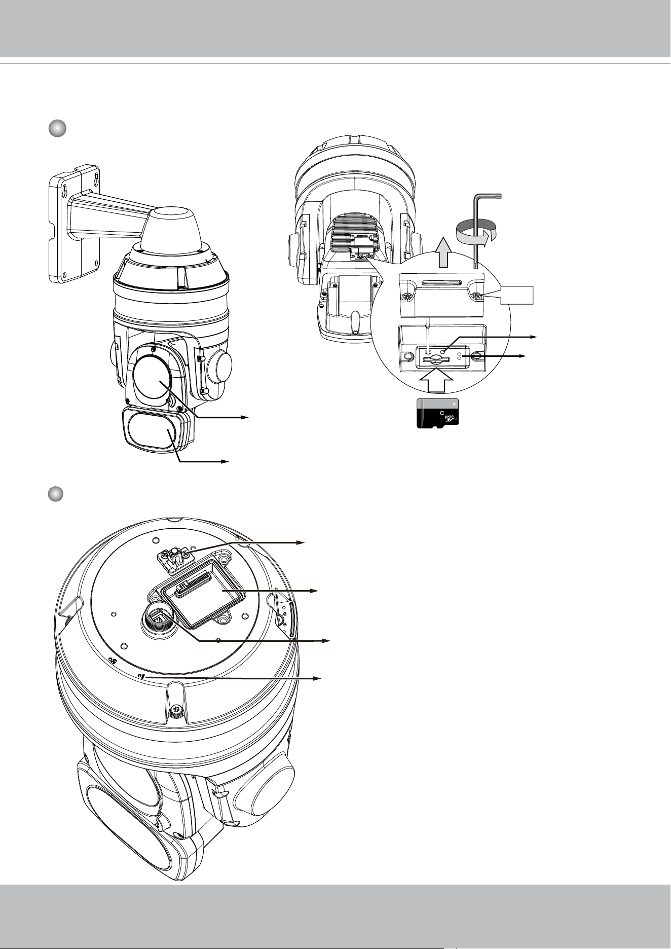
Physical Description
Outer View
Inner View
T10
64
GB
10
I
1
SD card slot
Lens
IR LEDs
LAN connector
Safety wire anchor
I/O combo connectors
Alignment marks
Reset button
LEDs
VIVOTEK
8 - User's Manual
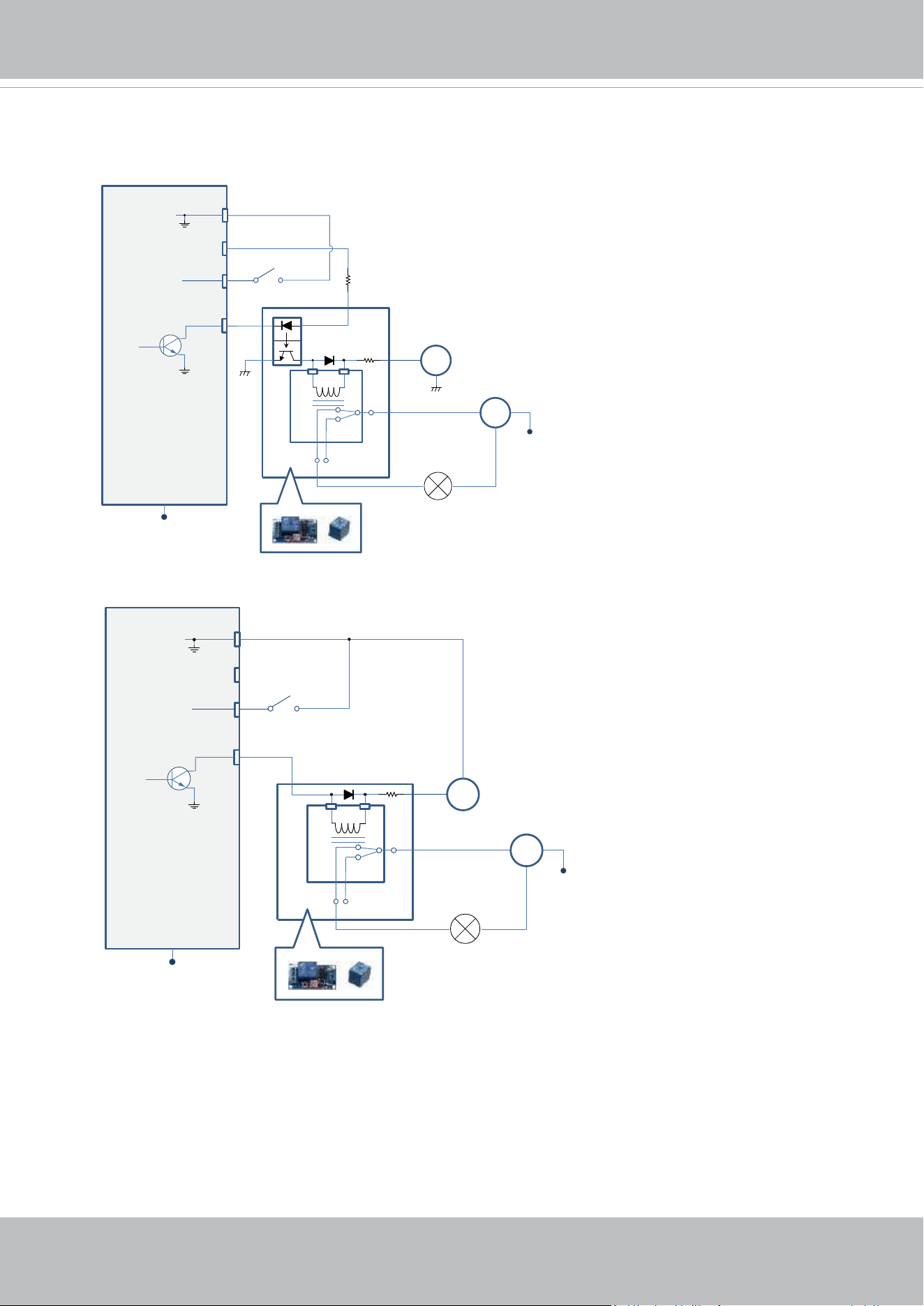
DI/DO Diagram
DI-
DO+
DI+
DO-
Switch
External Device
External DC power
Dry contact with external DC power source to supply a relay. Dry contact is the safest connecon
to protect devices.
NC
NO
Relay
Photo
Coupler
DC
DC 0V
DC 0V
External AC power
with Protected Earth
AC
PE
PE
DI-
DO+
DI+
DO-
Switch
External Device
External DC power
Wet contact with external DC power source to supply a relay.
NC
NO
Relay
DC
External AC power
with Protected Earth
AC
PE
PE
DC 0V
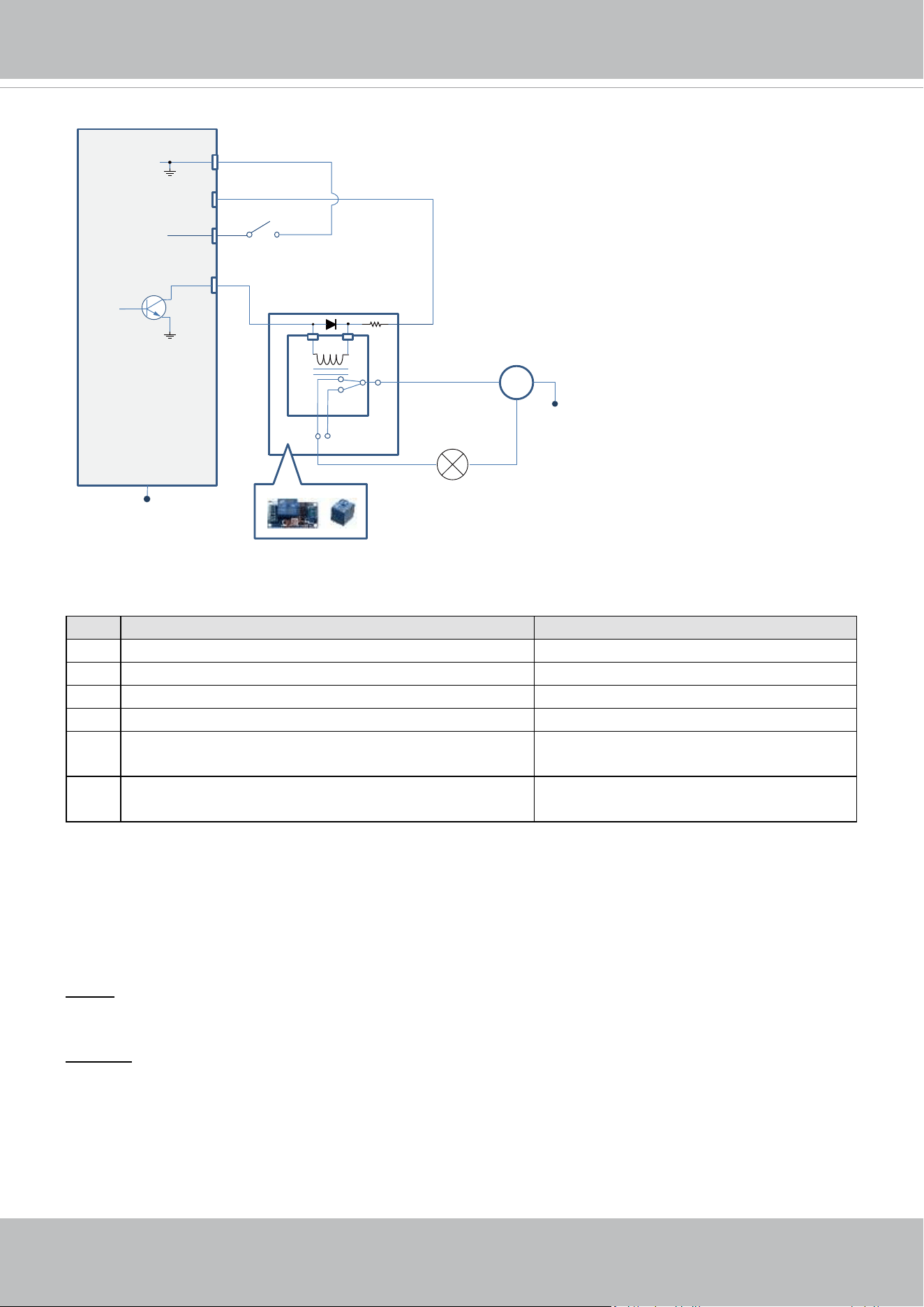
1. The DO+ pin provides 12V output voltage, and the max. load is 50mA.
2. The max. voltage for DO- pins is 30VDC (External power).
In order to control AC devices, the above diagram can be taken in consideration. The diagram
uses a relay to control the ON/OFF condition of the AC device.
3. An external relay can be triggered by using DO+ or by an external power source, depending
on the type of relay you use.
4. In case of using an individual relay (instead of using a relay module), for protection against
voltage or current spikes, a transient voltage suppression diode must be connected in parallel
with the inductive load.
VIVOTEK
User's Manual - 9
Status LED
Item LED status Description
1 Steady
red Power on and system booting
Red LED OFF Power off
2 Steady red & Green blinking every 1 sec. Network normal (heartbeat)
Steady red & Green LED OFF Network failed
3 Red blinking every 0.15 sec. & Green blinking
every 1 sec.
Upgrading rmware
4 Red blinking every 0.15 sec. & Green blinking
every 0.15 sec.
Restoring default
Hardware Reset
The reset button is used to reset the system or to restore the factory default settings. Sometimes
resetting the system can return the camera to normal operation. If the system problems remain
after reset, restore the factory settings and install again.
Reset: Press and release the reset button with a paper clip or thin object. Wait for the Network
Camera to reboot.
Restore: Press and hold the reset button for at least ten seconds to restore system defaults.
Note that all settings will be restored to factory defaults.
SD/SDHC/SDXC Card Capacity
This network camera is compliant with SD/SDHC/SDXC 32GB, 64GB, and other preceding
standard SD cards.
DI-
DO+
DI+
DO-
Switch
External Device
Dry contact and using camera’s DO+ to supply a relay.
NC
NO
Relay
AC
External AC power
with Protected Earth
PE
PE
VIVOTEK
10 - User's Manual
Hardware Installation
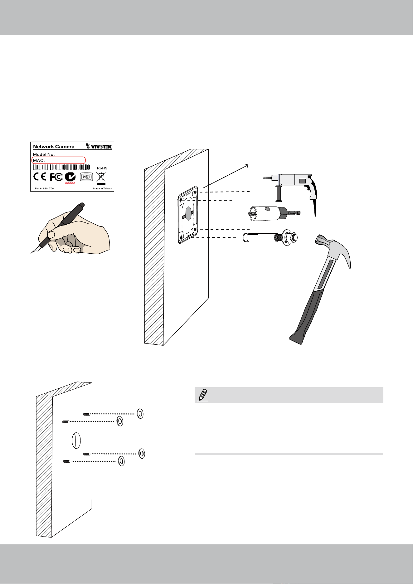
Ø 9.5mm or 3/8”
1. Jot down the camera's MAC address for later reference.
2. The camera weighs 6kg. Select a rigid mounting location to prevent vibration to the camera.
Attach the alignment sticker to the wall.
3. Drill 4 pilot holes (9.5mm in diameter and 4cm deep) into the wall, and then hammer in
threaded anchors. Note that you should hammer the anchors with hex nuts on them so that
the threaded poles will not be deformed! If preferred, drill another hole for routing cables.
4. Remove the hex nuts, washers, and leave one washer on each of the threaded poles.
0002D10766AD
SDXXXX
1. I/O wires are user-supplied.
2. Avoid touching the circuit boards to prevent
damage by electro static discharge.
3. Use CAT5e, CAT6 cables only.
NOTE:
VIVOTEK
User's Manual - 11
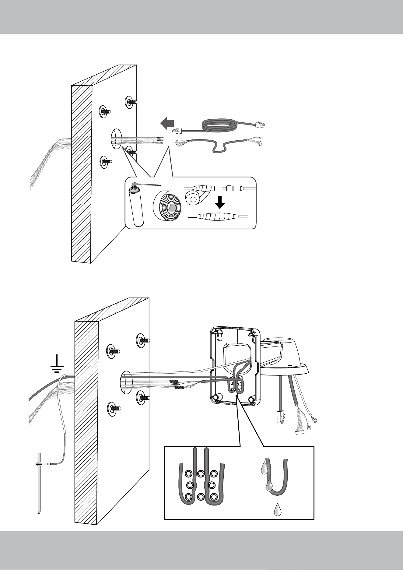
LAN I/O combo
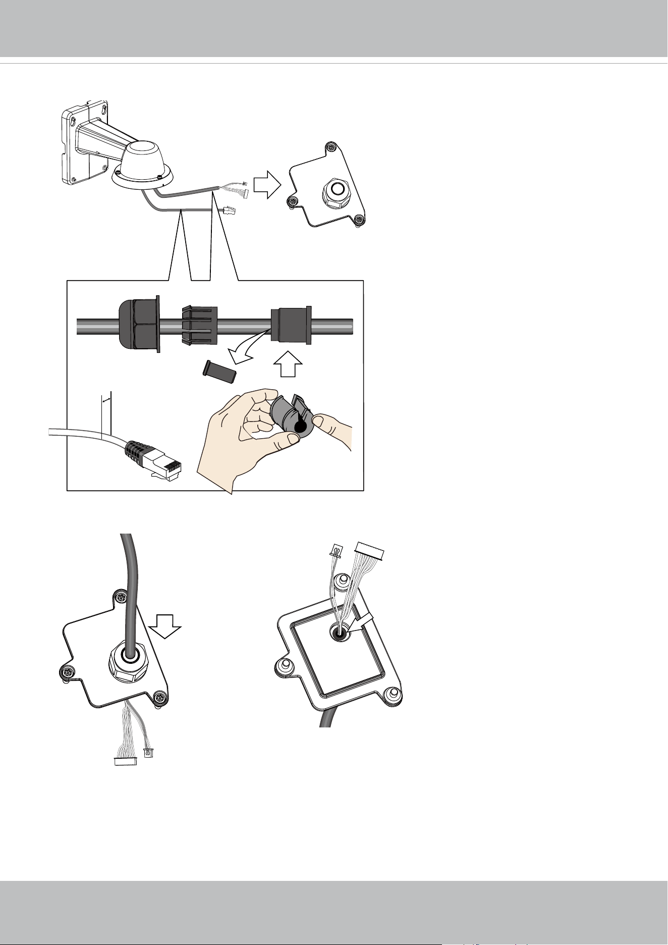
5. Connect power or I/O wires, and use foam tapes or seal foam to ensure the back-end
connection is waterproof.
6. Route your I/O combo and Ethernet cables along the routing guide poles to form drip loops.
Prepare a ground wire through the bracket.
VIVOTEK
12 - User's Manual
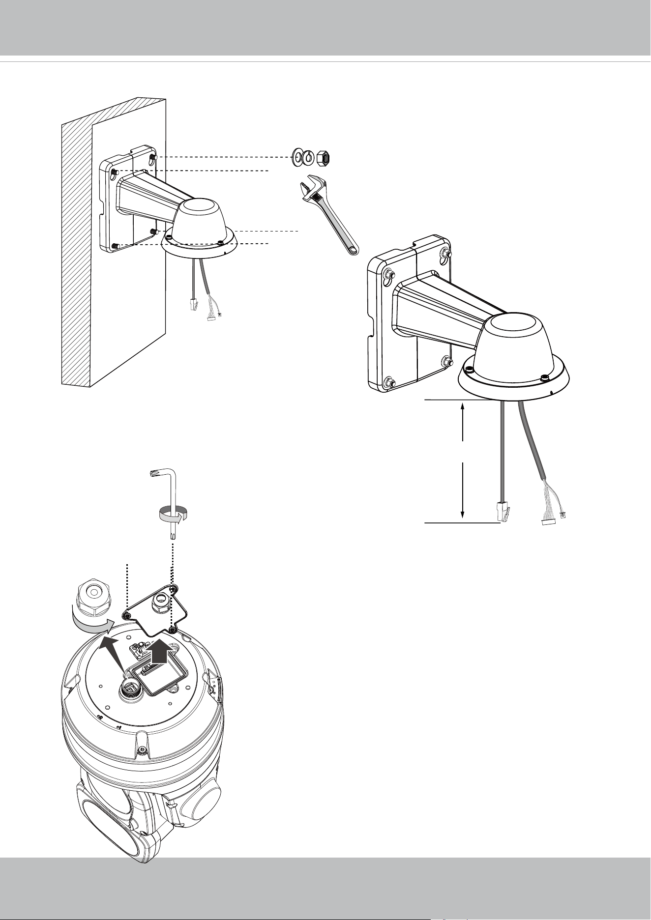
7. Secure the bracket to wall.
15cm
8. Remove the cable gland from the LAN port. If I/O wires or
24V power are preferred, use the T20 L-wrench to remove
the top cover on the I/O connector socket.
The cable length hanging on the outside of
the bracket should be 15cm.
T20
VIVOTEK
User's Manual - 13
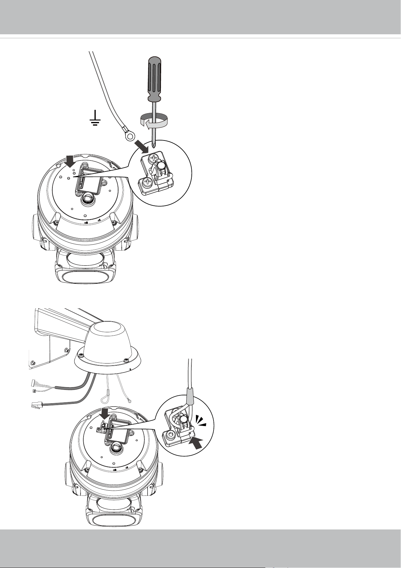
9. Install the safety wire anchor and secure a self-supplied ground wire to one of its screws.
10. Hook up the safety wire between the bracket and the camera.
VIVOTEK
14 - User's Manual
4.3 ~ 6.4mm
11. Install the components of the waterproof cable gland to the Ethernet and I/O combo cables.
12. Make sure the outer jacket of the combo cable is ush with the cabling hole.
VIVOTEK
User's Manual - 15
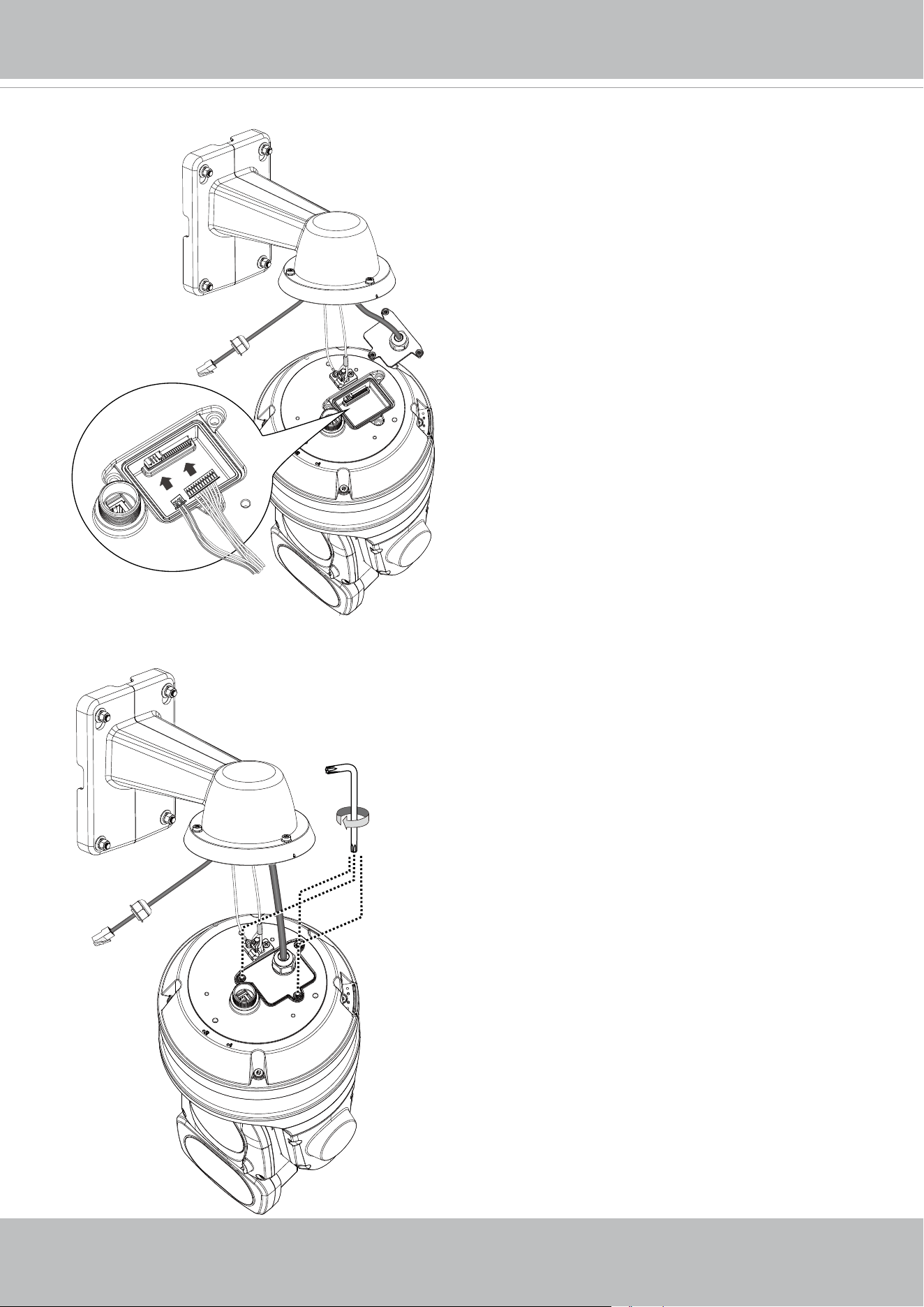
13. Connect the I/O wire headers to camera.
14.Secure the top cover of the I/O wire socket.
T20
VIVOTEK
16 - User's Manual
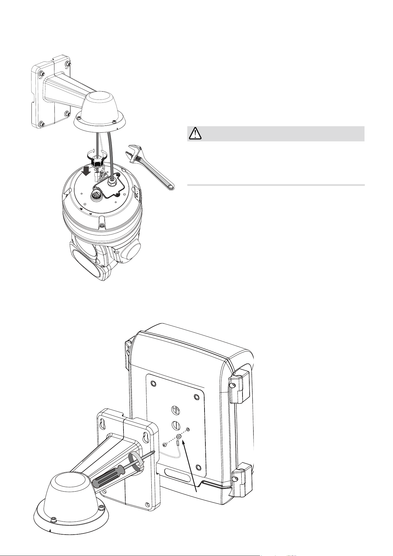
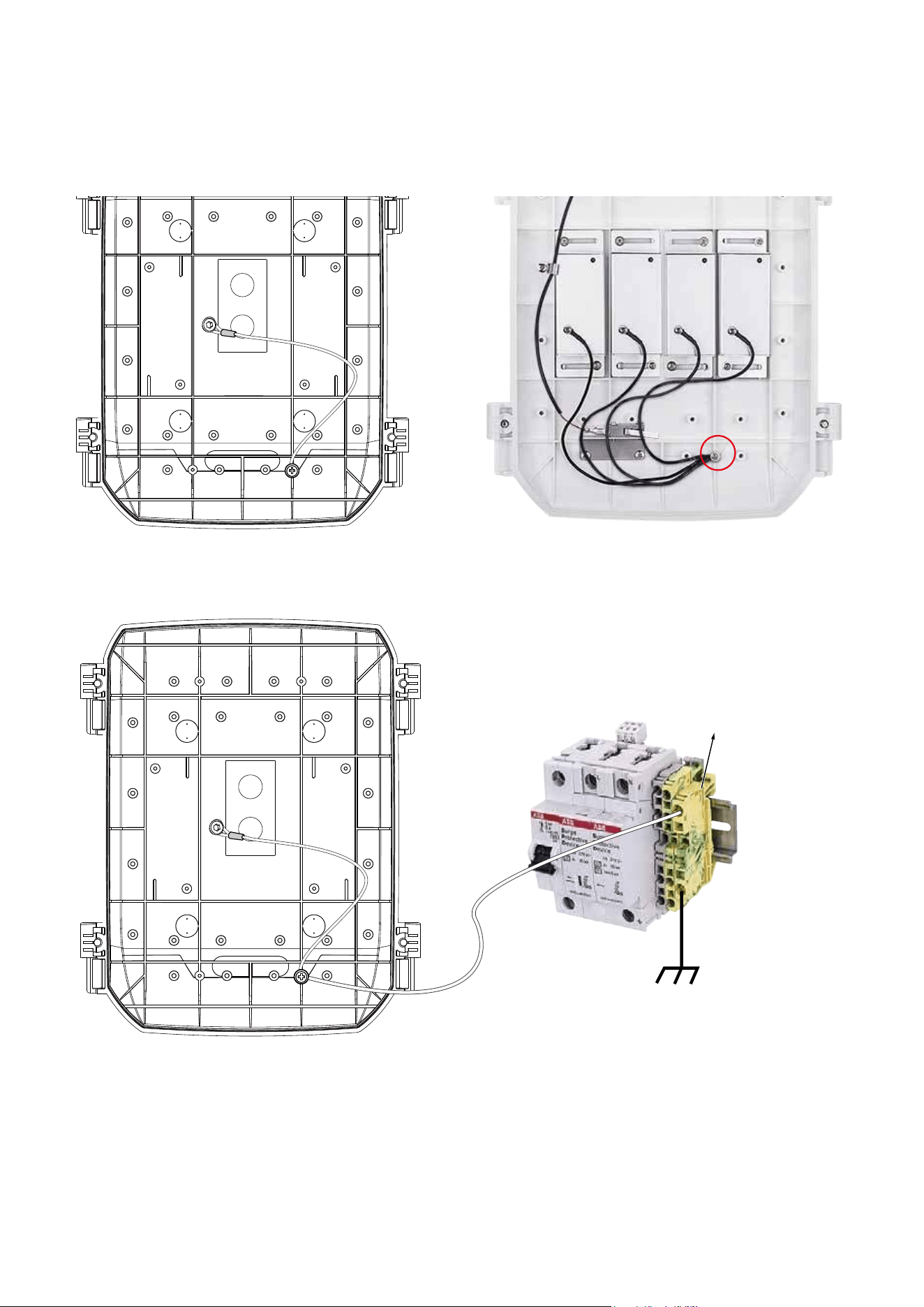
Camera ground wire
Connect the ground wire to the copper screw hole on the cabinet door.
OPTIONAL: If using VIVOTEK's outdoor cabinet.
15. Connect the Ethernet cable (along with its cable gland) to the camera.
IMPORTANT:
Make sure all waterproof cable glands have
been properly installed. Water leakage will cause
irrepairable damage to the camera.
VIVOTEK
User's Manual - 17
Connect all ground wires (including those from the surge protectors) to one position on the
cabinet door, to the terminal block, and then to the external ground. Several surge protectors
are shown in here.
External ground
AWG 8
Ground
VIVOTEK
18 - User's Manual
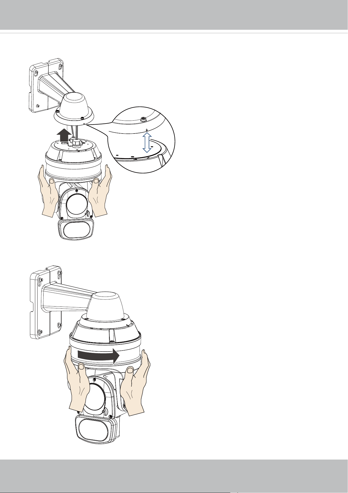
16. Install the camera to bracket by aligning the mark on bracket with the #1 marking on the cam-
era.
17. Turn the camera clockwise. The camera should be locked in place.
1
2
VIVOTEK
User's Manual - 19
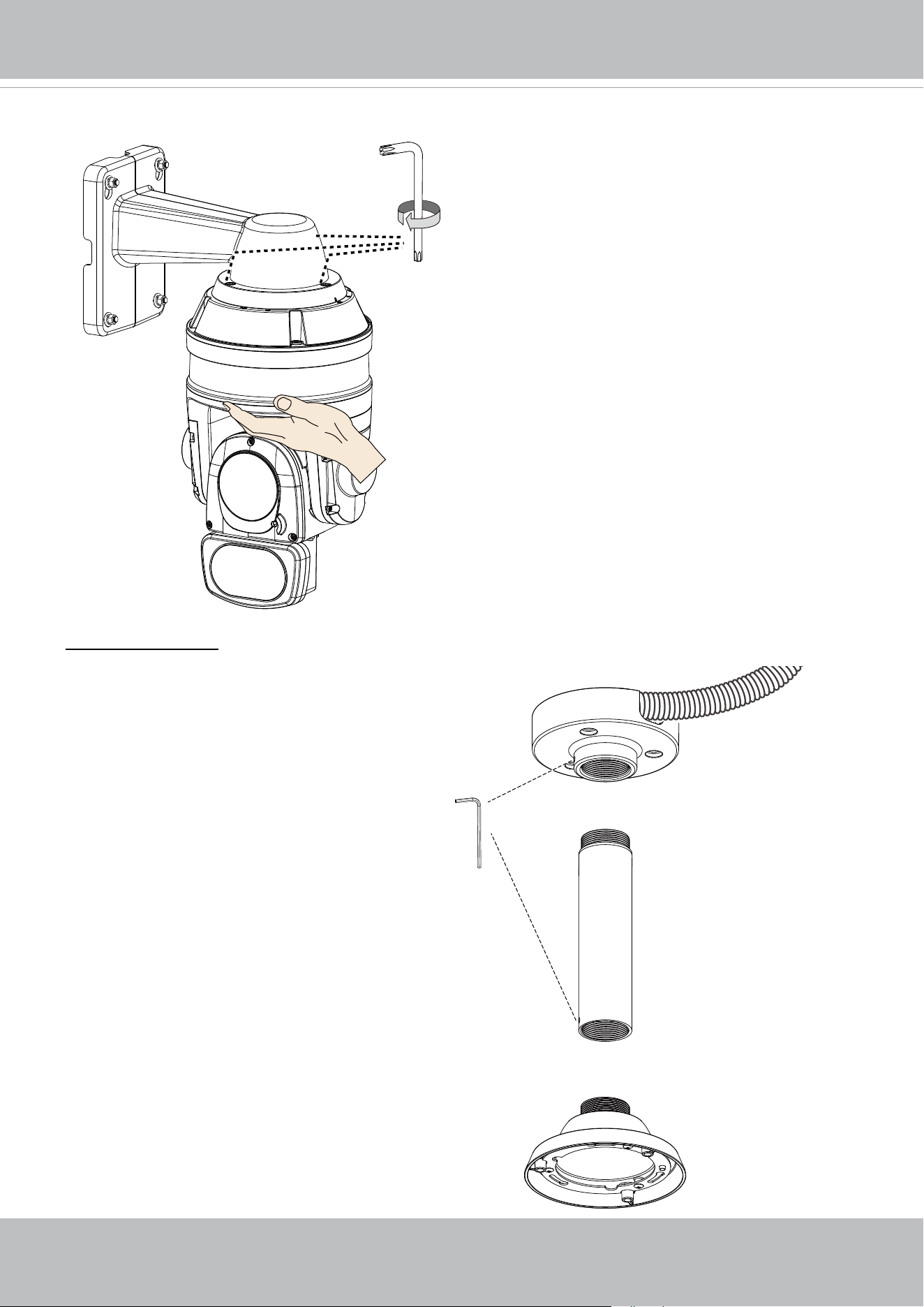
18. Secure the connection using the T25 L-wrench from the top.
AM-118
AM-116/117
3/4”
AM-529
The camera can also be mounted through a
pendant mount combination as shown below.
The rest of the installation prcedure is the same
as described above.
Pendant Mount
T25
VIVOTEK
20 - User's Manual
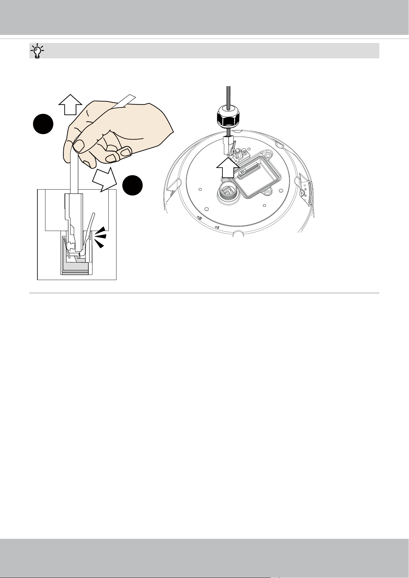
Tips:
To disconnect a LAN cable, loosen the cable gland and pull the cable against the socket wall
towards the side of the locking tab.
1
2
VIVOTEK
User's Manual - 21
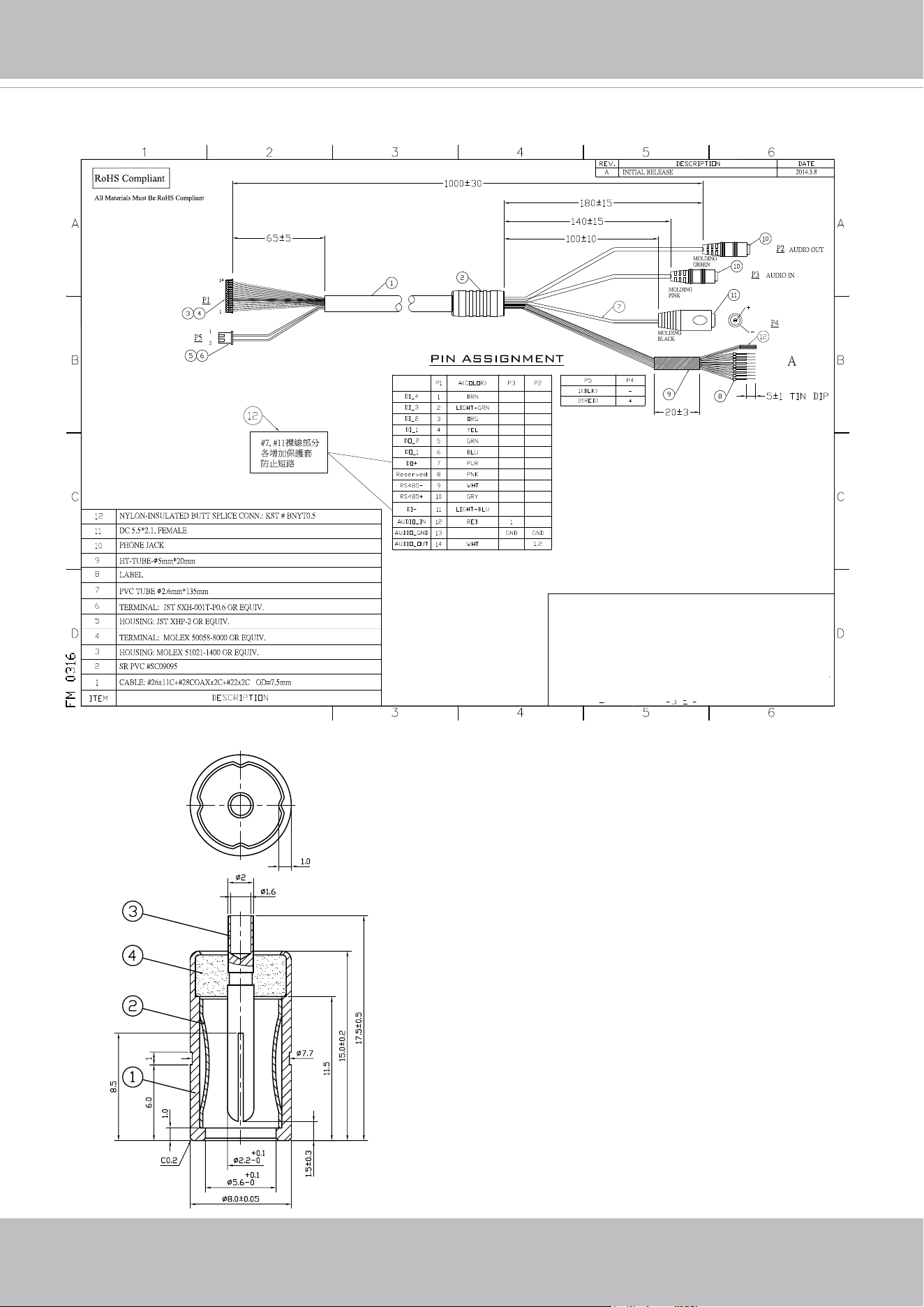
I/O Combo Cable Specications
Name
Tags
5.5x2.1 DC straight round barrel
all dimensions in mm
The 24V DC socket dimensions are shown on the
left. The DC socket should comply with a DC jack of
the following parameters:
Connector: Straight Round Barrel
Pin Size /DC Plug dimensions: 2.1 x 5.5 x 10 mm
(AxBxC)
A Inner diameter - 2.1mm
B Outer diameter - 5.5mm
C Length - 10 mm
VIVOTEK
22 - User's Manual
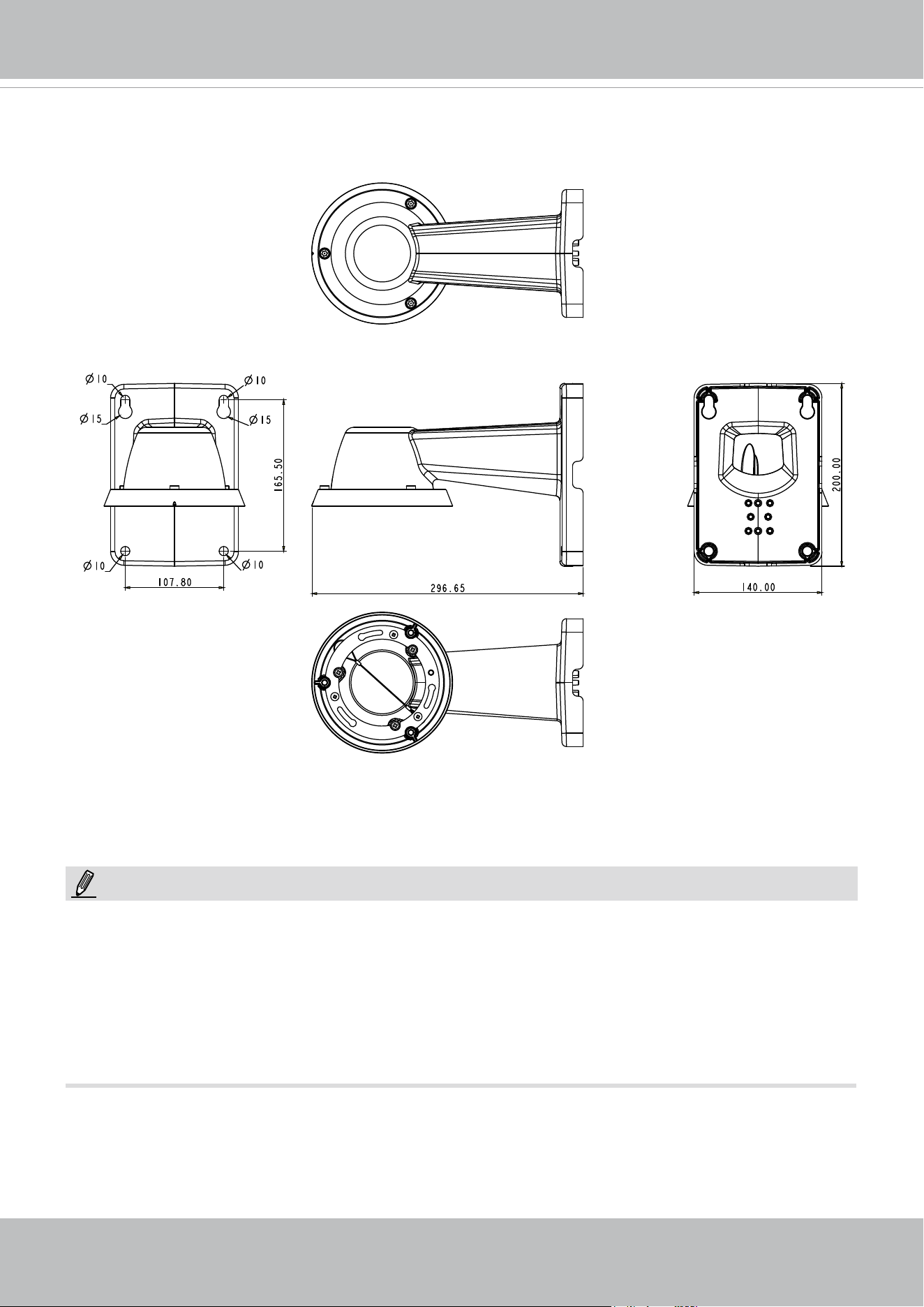
Mechanical Dimensions
Shown below are the dimensions of the wall mount bracket and its mounting holes:
You can nd the installation instructions on VIVOTEK’s website for other options such as para-
pet mount: http://www.vivotek.com/web/product/accessories.aspx
NOTE:
1. The camera is only to be connected to PoE networks without routing to outside plants.
2. For PoE connection, use only UL listed I.T.E. with PoE output.
1. La caméra ne doit être raccordée qu’à des réseaux PoE, sans routage vers des installations
extérieures.
2. Pour les raccordements PoE, utilisez uniquement un équipement de TI homologué UL, avec une sortie
PoE.
VIVOTEK
User's Manual - 23
Network Deployment
Setting up the Network Camera over the Internet
There are several ways to set up the Network Camera over the Internet. The rst way is to set
up the Network Camera behind a router
. The second way is to utilize a static IP. The third way is
to use PPPoE
.
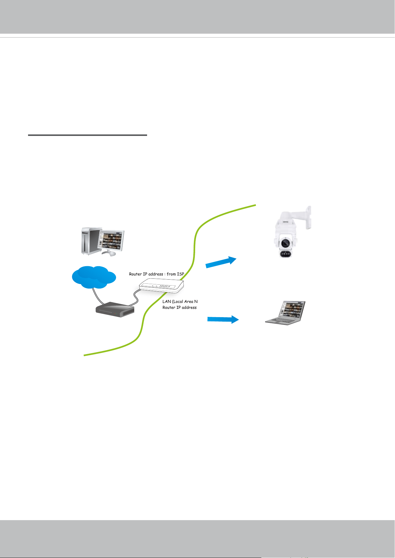
Internet connection via a router
Before setting up the Network Camera over the Internet, make sure you have a router and follow
the steps below.
1. Connect your Network Camera behind a router, the Internet environment is illustrated below.
Regarding how to obtain your IP address, please refer to Software Installation on page 26 for
details.
2. In this case, if the Local Area Network (LAN) IP address of your Network Camera is
192.168.0.3, please forward the following ports for the Network Camera on the router.
■ Secondary HTTP port: 8080
■ RTSP port: 554
■ RTP port for audio: 5558
■ RTCP port for audio: 5559
■ RTP port for video: 5556
■ RTCP port for video: 5557
If you have changed the port numbers on the Network page, please open the ports accordingly
on your router. For information on how to forward ports on the router, please refer to your
router’s user’s manual.
3. Find out the public IP address of your router provided by your ISP (Internet Service Provider).
Use the public IP and the secondary HTTP port to access the Network Camera from the
IP address : 192.168.0.3
Subnet mask : 255.255.255.0
Default router : 192.168.0.1
IP address : 192.168.0.2
Subnet mask : 255.255.255.0
Default router : 192.168.0.1
LAN (Local Area Network)
Router IP address : 192.168.0.1
WAN (Wide Area Network )
Router IP address : from ISP
Cable or DSL Modem
POWER
COLLISION
LINK
RECEIVE
PARTITION
1
2
3
4
5
Internet
VIVOTEK
24 - User's Manual
Internet. Please refer to Network Type on page 80 for details.
For example, your router and IP settings may look like this:
Device IP Address: internal
port
IP Address: External Port (Mapped port on the
router)
Public IP of router 122.146.57.120
LAN IP of router 192.168.2.1
Camera 1 192.168.2.10:80 122.146.57.120:8000
Camera 2 192.168.2.11:80 122.146.57.120:8001
... ... ...
Congure the router, virtual server or rewall, so that the router can forward any data coming
into a precongured port number to a network camera on the private network, and allow data
from the camera to be transmitted to the outside of the network over the same path.
From Forward to
122.146.57.120:8000 192.168.2.10:80
122.146.57.120:8001 192.168.2.11:80
... ...
When properly congured, you can access a camera behind the router using the HTTP request
as follows: http://122.146.57.120:8000
If you change the port numbers on the Network conguration page, please open the ports
accordingly on your router. For example, you can open a management session with your router
to congure access through the router to the camera within your local network. Please consult
your network administrator for router conguration if you have troubles with the conguration.
For more information with network conguration options (such as that of streaming ports),
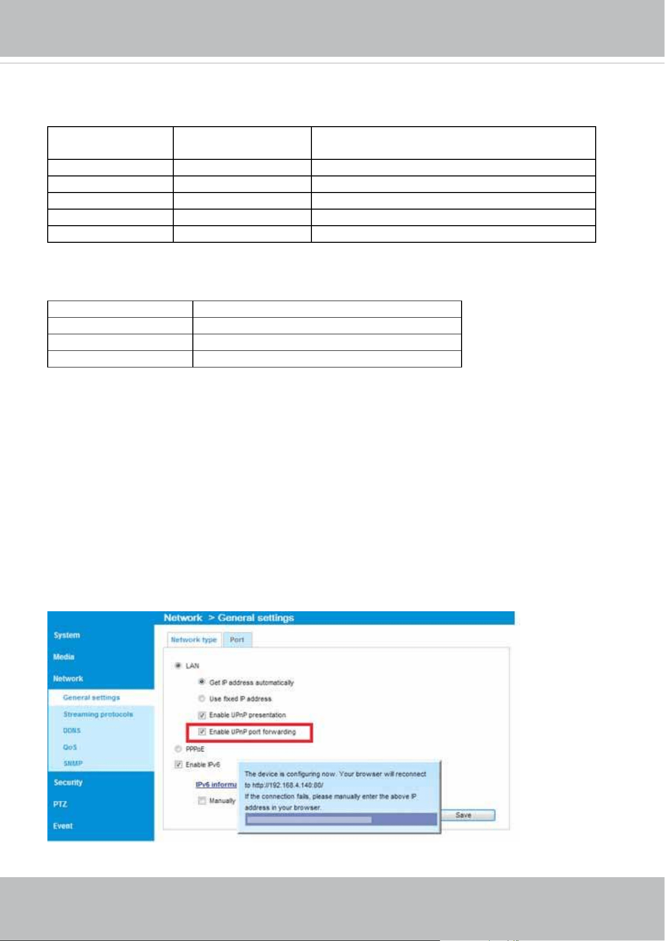
please refer to Conguration > Network Settings. VIVOTEK also provides the automatic port
forwarding feature as an NAT traversal function with the precondition that your router must
support the UPnP port forwarding feature.
VIVOTEK
User's Manual - 25
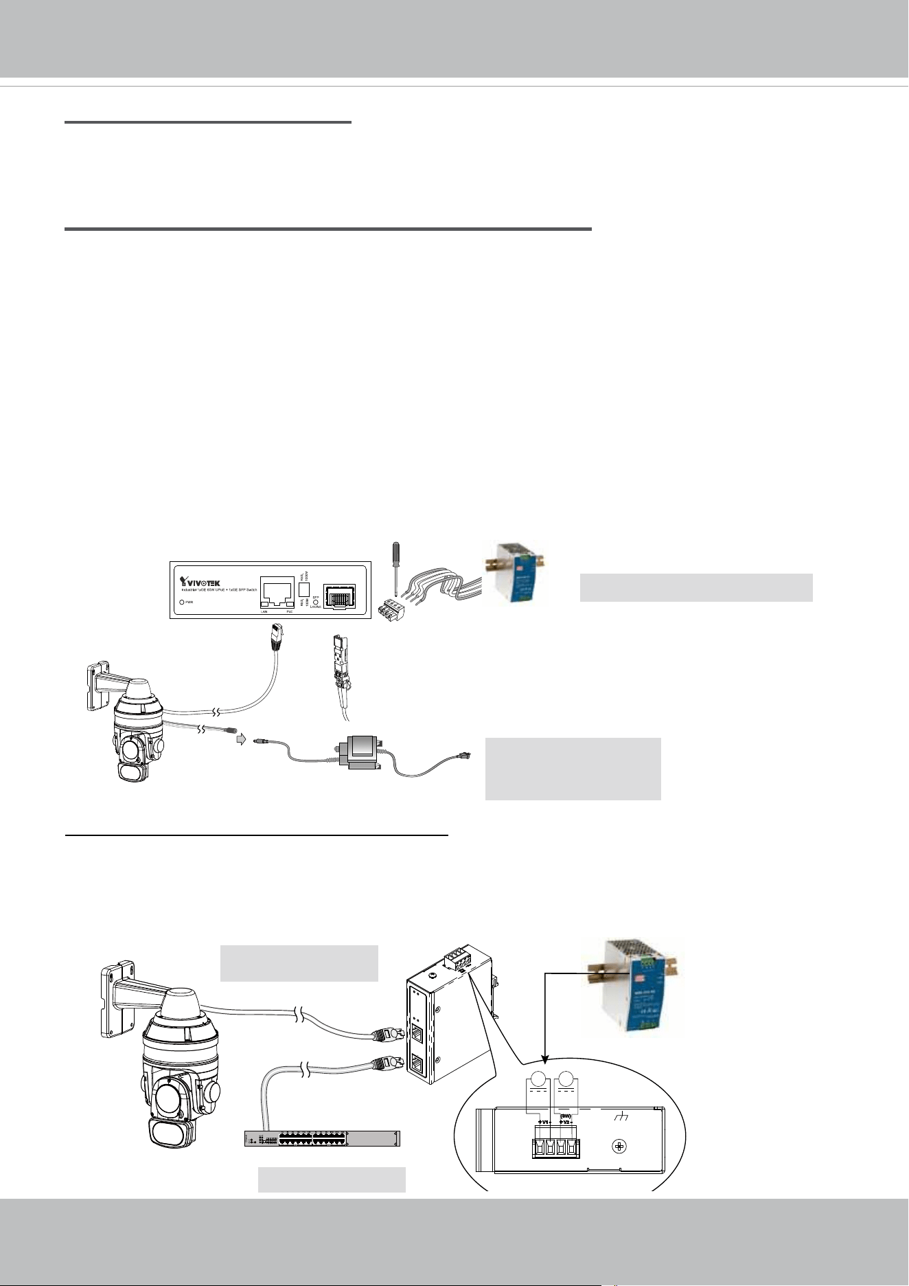
General Connection
LC
AC-to-DC power
100~240 VAC IN
1. Connect the Network Camera's Ethernet cable (CAT5e) to a PoE Plus switch. A 30W PoE
output port alone can not drive the onboard heater, and hence if using the PoE switch
alone, the application does not apply in low-temperature condition. When working under a
temperature lower than -10ºC, a DC 24V 2.3A power adapter is required.
48 ~ 56V DC
Chassis Ground
+
-
+
-
AC-to-DC power
100~240 VAC IN
When using a non-PoE switch
Use a High Power PoE power injector (separately purchased) capable of 60W output or higher
to connect between the Network Camera and a non-PoE switch. Sufcient power is required for
low temperature conditions when the onboard heater is activated.
Non-PoE Switch
High Power PoE
Power Injector
2. Connect the power wires to a DC 24V power adaptor (user-supplied). The DC 24V adapter
can drive the camera and the onboard heater.
You can connect both power sources for redundancy in power supply.
Power over Ethernet (High Power PoE)
DC 24V 2.3A
Adapter (Separately
purchasedied)
UPoE Switch (60W output)
and / or
Internet connection with static IP
Choose this connection type if you are required to use a static IP for the Network Camera.
Please refer to LAN on page 80 for details.
Internet connection via PPPoE (Point-to-Point over Ethernet)
Choose this connection type if you are connected to the Internet via a DSL Line. Please refer to
PPPoE on page 81 for details.
VIVOTEK
26 - User's Manual
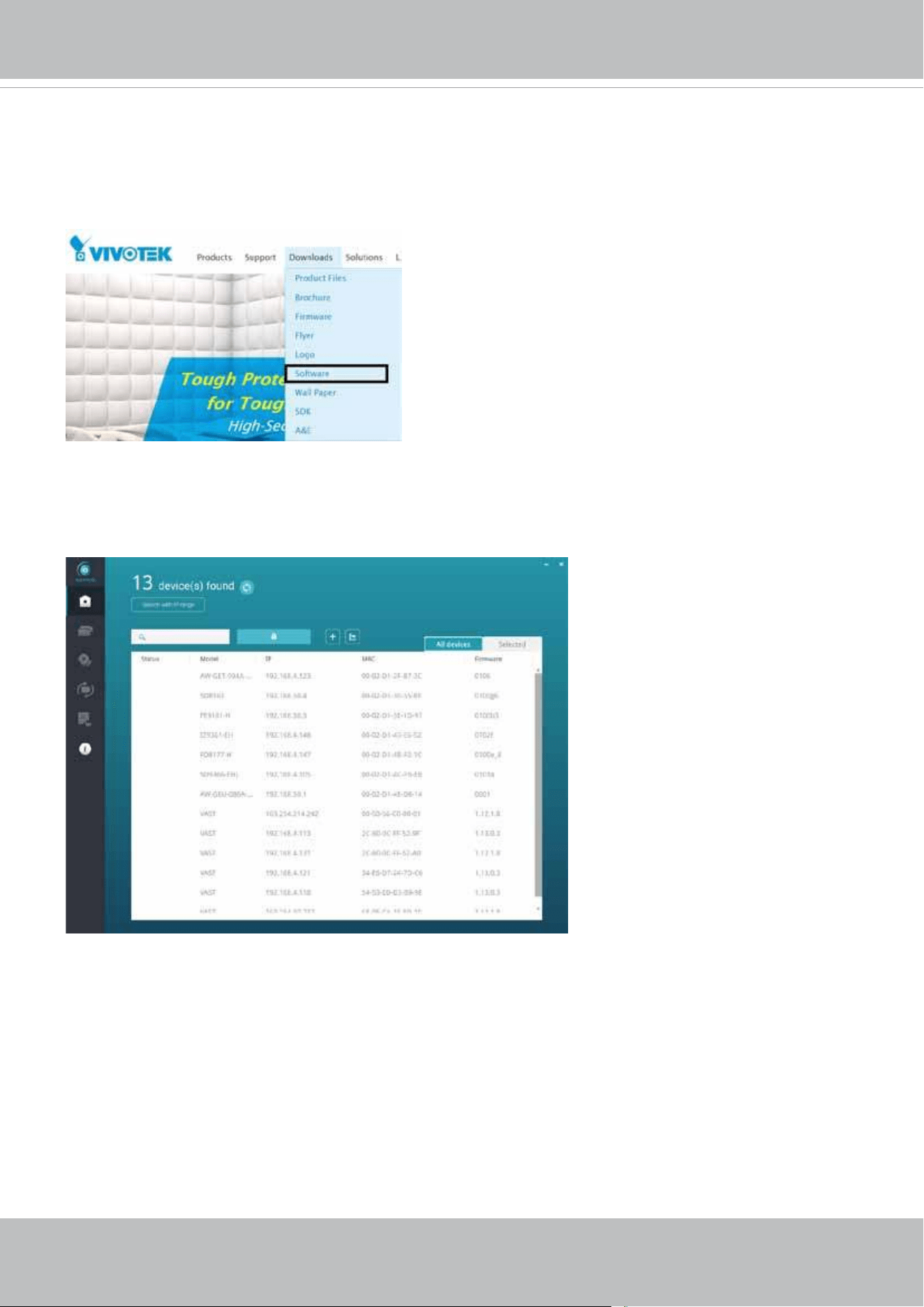
Software Installation
19. Install the Shepherd utility, which helps you locate and congure your Network Camera
in the local network. If your camera comes without the CD, go to VIVOTEK’s website,
and locate the utility in the Downloads > Software page.
19-1. Run the Shepherd utility.
19-2. The program will conduct an analysis of your network environment.
VIVOTEK
User's Manual - 27
0002D1730202
IB8360-W 192.168.4.151 00-02-D1-73-02-02
SD9363-EHL
Network Camera
Model No: SD9363-EHL
Made in Taiwan
This device complies with part 15 of the FCC rules. Operation is subject to the following two conditions:
(1)This device may not cause harmful interference, and
(2) this device must accept any interference received, including interference that may cause undesired operation.
Pat. 6,930,709
MAC:0002D1730202
R o H S
19-3. The program will search for all VIVOTEK network devices on the same LAN.
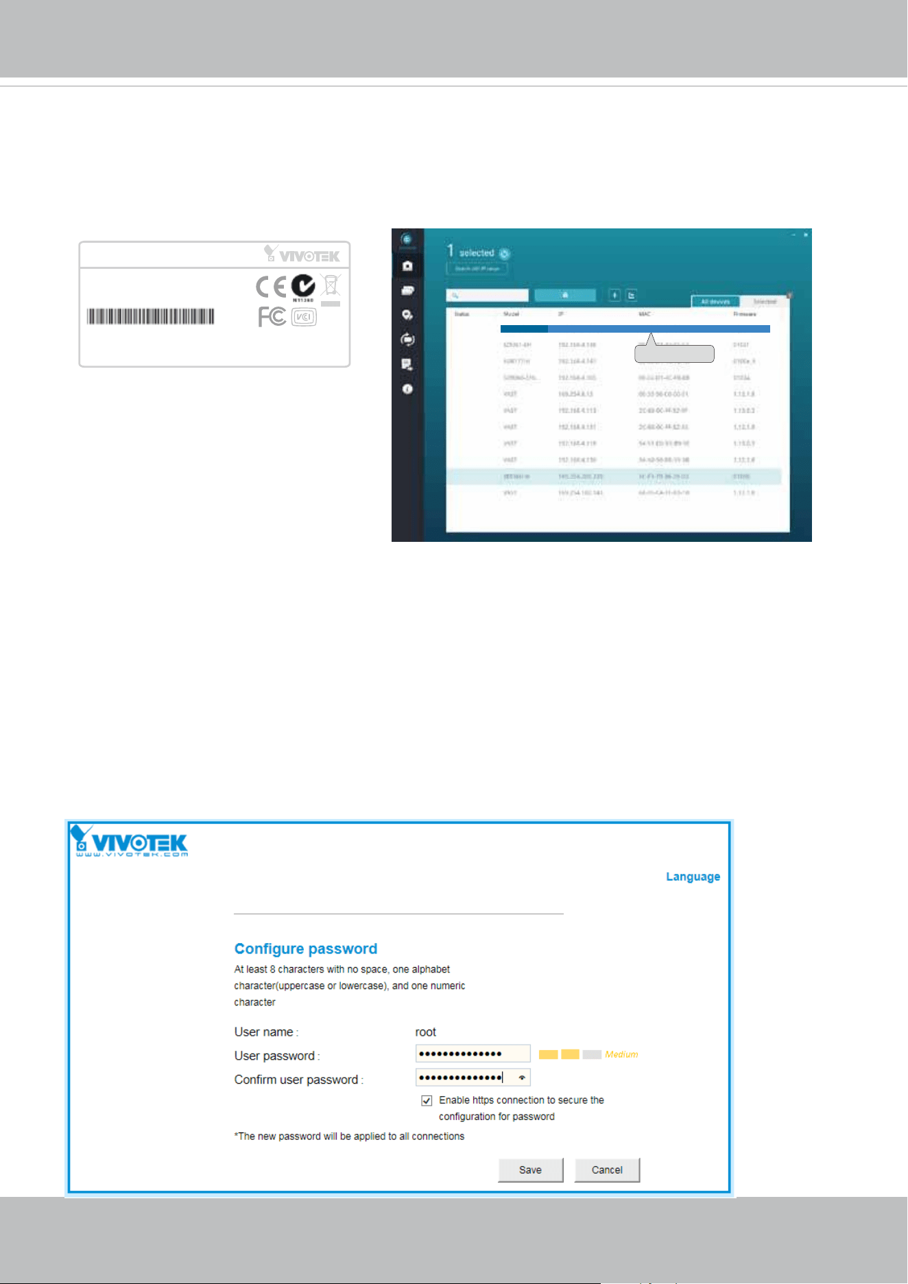
19-4. After a brief search, the installer window will prompt. Click on the MAC and model
name that matches the one printed on the product label. You can then double-click on
the address to open a management session with the Network Camera.
Forceful Password Conguration
20. The first time you log in to the camera, the firmware will prompt for a password
conguration for security concerns.
20-1. Enter the combination of alphabetic and numeric characters to fulll the password
strength. requirement. The default name for the camera administrator is “root”, and can
not be changed.
VIVOTEK
28 - User's Manual
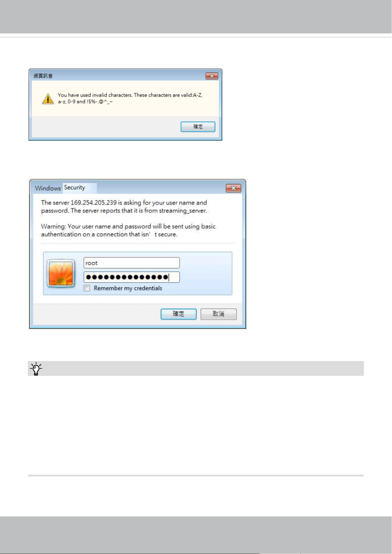
Some, but not all special ASCII characters are supported: !, $, %, -, ., @, ^, _, and ~.
You can use them in the password combination.
20-2. Another prompt will request for the password you just congured. Enter the password and
then you can start congure your camera and see the live view.
1. If you forget the root (administrator) password for the camera, you can restore the camera
defaults by pressing the reset button for longer than 5 seconds.
2. If DHCP is enabled in your network, and the camera cannot be accessed, run the Shepherd
utility to search the network. If the camera has been congured with a xed IP that does not
comply with your local network, you may see its default IP 169.254.x.x. If you still cannot nd
the camera, you can restore the camera to its factory defaults. The factory default is DHCP
client.
3. If you change your network parameters, e.g., added a camera via a connection to a LAN card,
re-start the Shepherd utility.
Tips:
VIVOTEK
User's Manual - 29
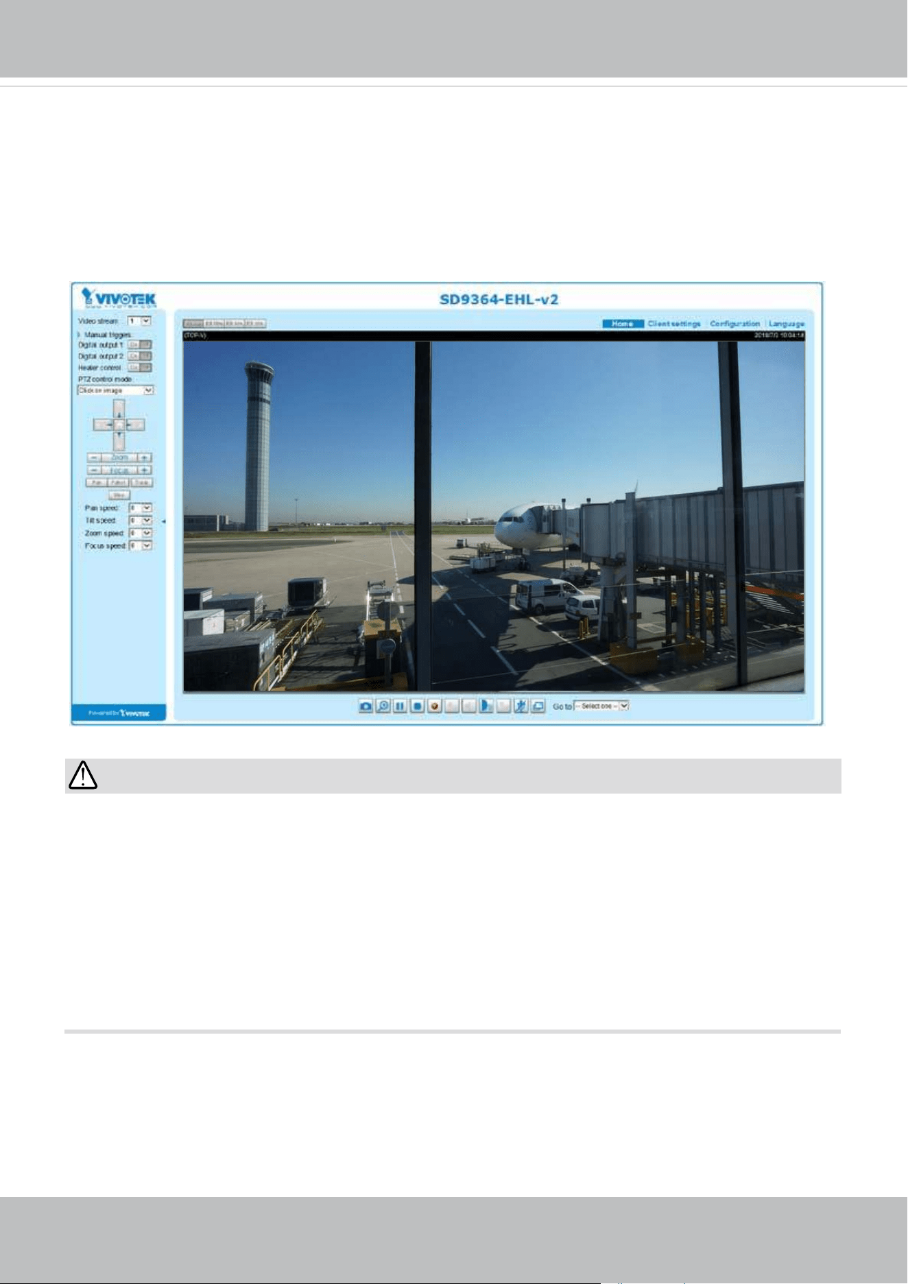
Ready to Use
1. A browser session to the Network Camera should prompt as shown below.
2. You should be able to see live video from your camera. You may also install the 32-channel
VAST recording software in a deployment consisting of multiple cameras. For its installation
details, please refer to its related documents.
•
Currently the Network Camera utilizes a 32-bit ActiveX plugin. You CAN NOT open a
management/view session with the camera using a 64-bit IE browser.
•
If you encounter this problem, try execute the Iexplore.exe program from C:\Windows\
SysWOW64. A 32-bit version of IE browser will be installed.
•
On Windows 7, the 32-bit explorer browser can be accessed from here: C:\Program Files
(x86)\Internet Explorer\iexplore.exe
•
If you experience compatibility issues between the plug-in control, you may try to uninstall
the Camera Stream Controller located in: C:/Program Files (x86)/Camera Stream Controller.
30x
IMPORTANT:
VIVOTEK
30 - User's Manual
Accessing the Network Camera
This chapter explains how to access the Network Camera through web browsers, RTSP players,
3GPP-compatible mobile devices, and VIVOTEK recording software.
Using Web Browsers
Use the Shepherd software utility to access to the Network Cameras on the LAN.
If your network environment is not a LAN, follow these steps to access the Netwotk Camera:
1. Launch your web browser (e.g., Microsoft
®
Internet Explorer or Mozilla Firefox).
2. Enter the IP address of the Network Camera in the address eld. (A temporary IP will be
generated for the camera. Find it in your Network Neighborhood). Press Enter.
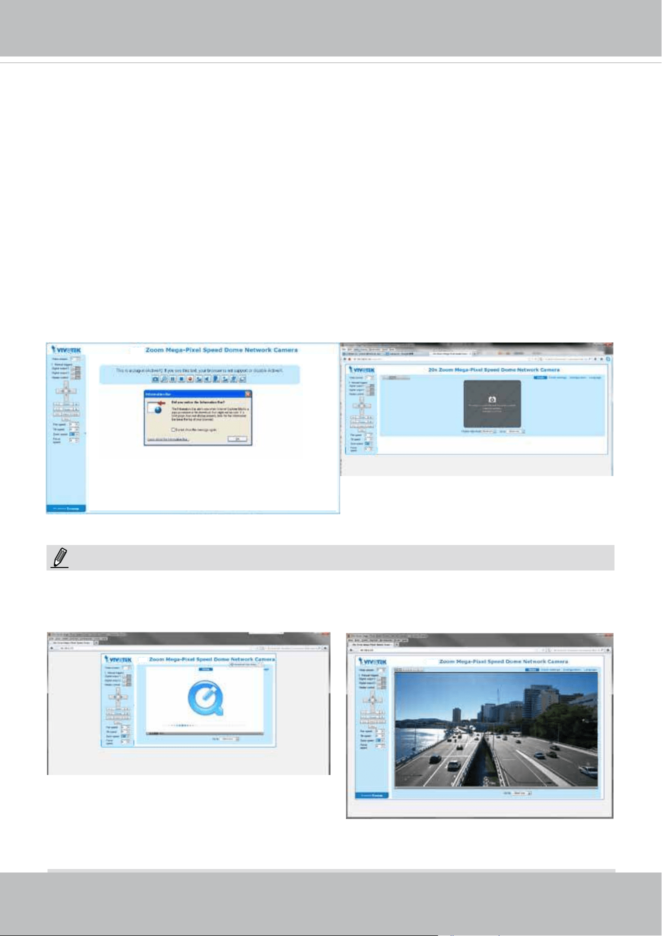
3. Live video will display in your web browser.
4. If it is the rst time installing the VIVOTEK network camera, an information bar will pop up as
shown below. Follow the instructions to install the required plug-in on your computer.
For Mozilla Firefox or Netscape users, your browser will use QuickTime to stream live video.
If you do not have QuickTime on your computer, please download QuickTime from Apple Inc's
website, and then launch your web browser.
30x
28x
30x
NOTE:
VIVOTEK
User's Manual - 31
► By default, the Network Camera is not password-protected. To prevent unauthorized access,
it is highly recommended to set a password for the Network Camera.
For more information about how to enable password protection, please refer to Security on
page 100.
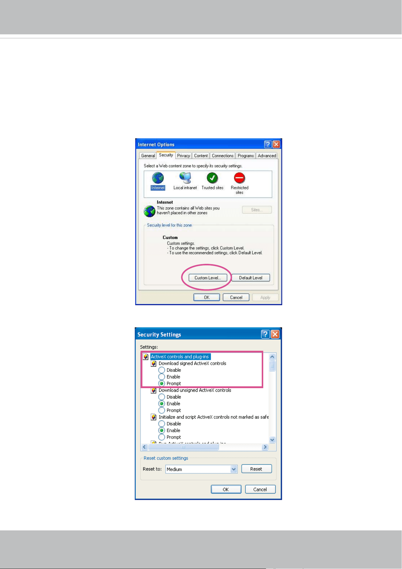
► If you see a dialog box indicating that your security settings prohibit running ActiveX
®
Controls, please enable the ActiveX
®
Controls for your browser.
1. Choose Tools > Internet Options > Security > Custom Level.
2. Look for Download signed ActiveX
®
controls; select Enable or Prompt. Click OK.
3. Refresh your web browser, then install the ActiveX
®
control. Follow the instructions to
complete installation.
VIVOTEK
32 - User's Manual
1. The onscreen Java control can malfunction under the following situations: A PC connects to
different cameras that are using the same IP address (or the same camera running different
rmware versions). Removing your browser cookies will solve this problem.
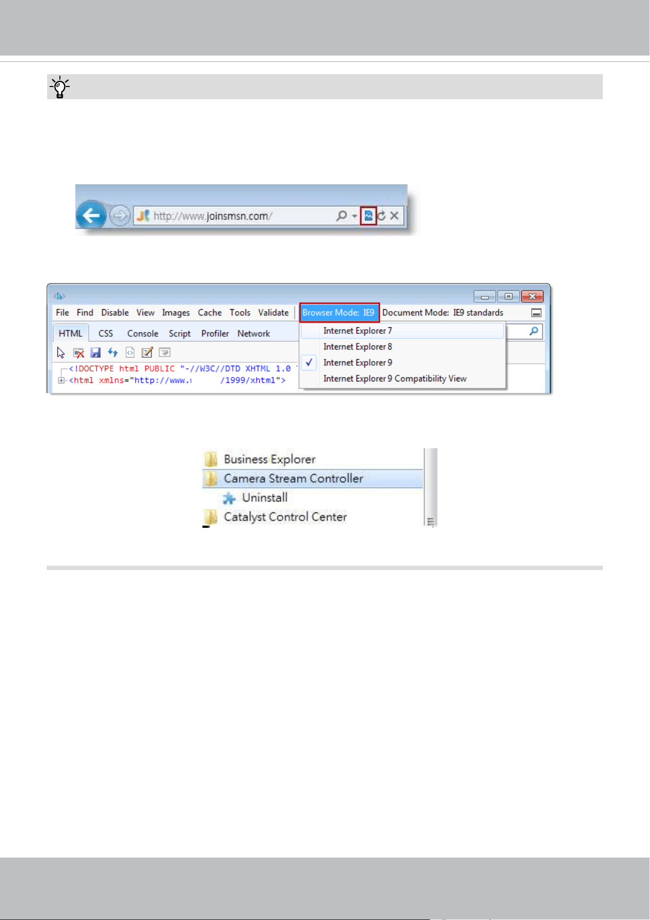
2. If you encounter problems with displaying the conguration menus or UI items, try disable
the Compatibility View on IE8 or IE9.
You may also press the F12 key to open the developer tools utility, and then change the
Browser Mode to the genuine IE8 or IE9 mode.
Tips:
• In the event of plug-in compatibility issues, you may try to uninstall the plug-in that was previ-
ously installed.
VIVOTEK
User's Manual - 33
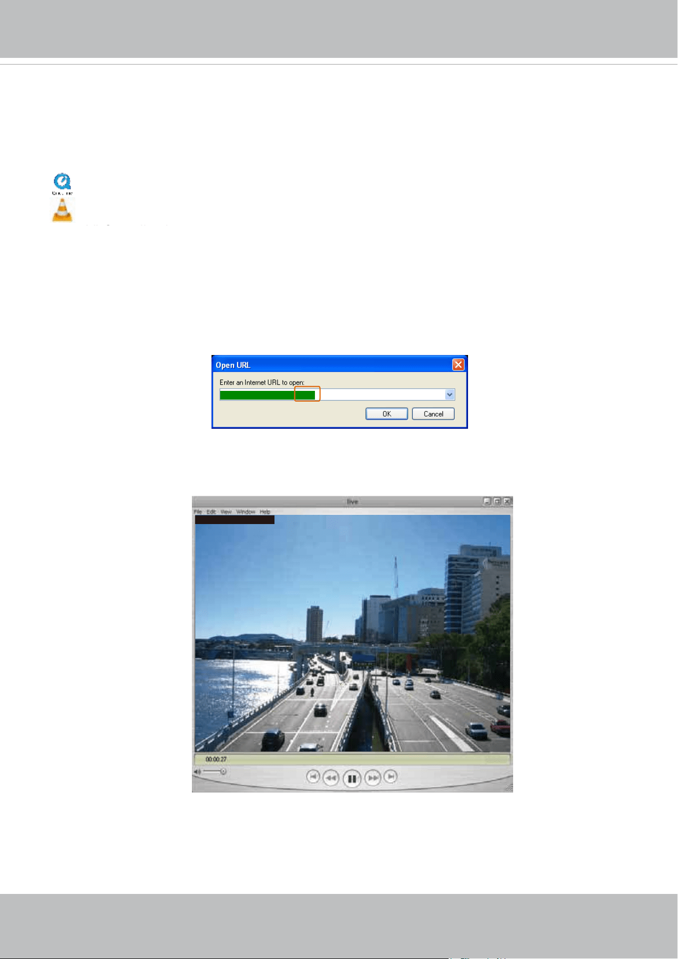
Using RTSP Players
To view the H.265/H.264 streaming media using RTSP players, you can use one of the following
players that support RTSP streaming.
Quick Time Player
VLC Media Player
VLC media player
mpegable Player
pvPlayer
As most ISPs and players only allow RTSP streaming through port number 554, please set the
RTSP port to 554. For more information, please refer to RTSP Streaming on page 88.
For example:
4. The live video will be displayed in your player.
For more information on how to configure the RTSP access name, please refer to RTSP
Streaming on page 88 for details.
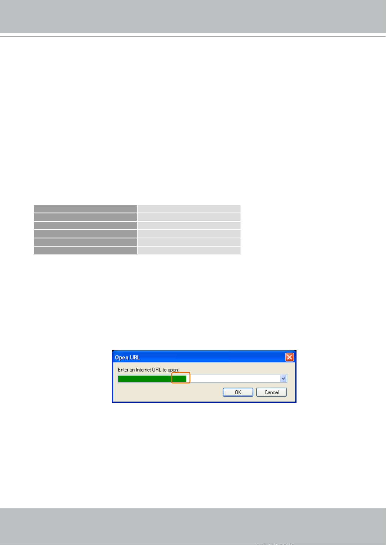
1. Launch the RTSP player.
2. Choose File > Open URL. An URL dialog box will pop up.
3. The address format is rtsp://<ip address>:<rtsp port>/<RTSP streaming access name for
stream1 or stream2>
rtsp://192.168.5.151:554/live.sdp
Video 16:38:01 2011/03/25
VIVOTEK
34 - User's Manual
Using 3GPP-compatible Mobile Devices
To view the streaming media through 3GPP-compatible mobile devices, make sure the Network
Camera can be accessed over the Internet. For more information on how to set up the Network
Camera over the Internet, please refer to Setup the Network Camera over the Internet on page
23.
To utilize this feature, please check the following settings on your Network Camera:
1. Because most players on 3GPP mobile phones do not support RTSP authentication, make
sure the authentication mode of RTSP streaming is set to disable.
For more information, please refer to RTSP Streaming on page 88.
2. As the the bandwidth on 3G networks is limited, you will not be able to use a large video size.
Please set the video and audio streaming parameters as listed below.
For more information, please refer to Stream settings on page 72.
Video Mode MPEG-4
Frame size 176 x 144
Maximum frame rate 5 fps
Intra frame period 1S
Video quality (Constant bit rate) 40kbps
Audio type (GSM-AMR) 12.2kbps
3. As most ISPs and players only allow RTSP streaming through port number 554, please set
the RTSP port to 554. For more information, please refer to RTSP Streaming on page 88.
4. Launch the player on the 3GPP-compatible mobile devices (ex. Real Player).
5. Type the following URL commands into the player.
The address format is rtsp://<public ip address of your camera>:<rtsp port>/<RTSP streaming
access name for stream 3>.
For example:
rtsp://192.168.5.151:554/live.sdp
VIVOTEK
User's Manual - 35
LIVE FD8177-HT
2688x1520
H264
29.97 fps 6.42 Mbit/s
2018/7/3 10:19:46
LIVE IP9191-HT
1280x800
H264
30 fps 0.5 Mbit/s
2018/7/3 10:19:46
LIVE SD9364-EHL-v2
1280x720
H264
29.97 fps 0.42 Mbit/s
2018/7/3 10:19:46
LIVE FE9180-H
1536x1536
H264
15 fps 0.57 Mbit/s
2018/7/3 10:19:46
LIVE IP9191-HT
1280x800
H264
30 fps 0.5 Mbit/s
2018/7/3 10:19:46
LIVE SD9364-EHL-v2
1280x720
H264
29.97 fps 0.42 Mbit/s
2018/7/3 10:19:46
LIVE FD8177-HT
2688x1520
H264
29.97 fps 6.42 Mbit/s
2018/7/3 10:19:46
LIVE IP9191-HT
1280x800
H264
30 fps 0.5 Mbit/s
2018/7/3 10:19:46
LIVE SD9364-EHL-v2
1280x720
H264
29.97 fps 0.42 Mbit/s
2018/7/3 10:19:46
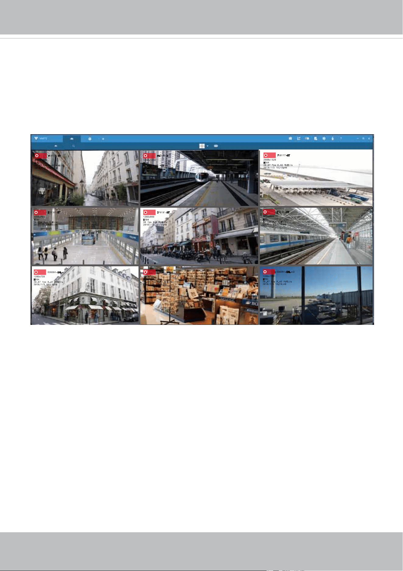
Using VIVOTEK Recording Software
You can visit VIVOTEK’s website for a VAST recording software, allowing simultaneous
monitoring and video recording for multiple Network Cameras. Please install the recording
software; then launch the program to add the Network Camera to the Channel list. For detailed
information about how to use the recording software, please refer to the user’s manual of the
software or download it from
http://www.vivotek.com.
VIVOTEK
36 - User's Manual
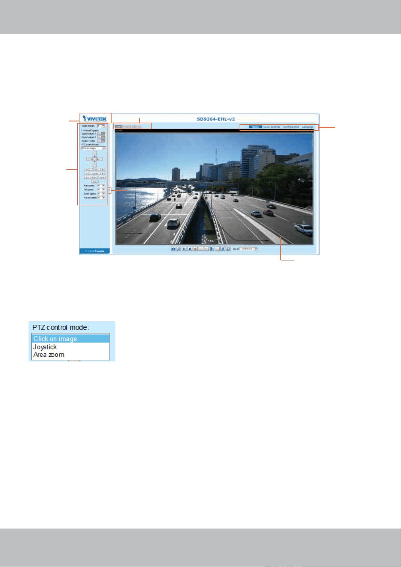
Main Page
This chapter explains the layout of the main page. It is composed of the following sections:
VIVOTEK INC. Logo, Host Name, Camera Control Area, Configuration Area, and Live Video
Window.
Live View Window
Host Name
VIVOTEK INC.
Logo
Camera Control
Area
Configuration
Area
Resize Buttons
Hide Button
Mouse and Screen Control
PTZ control mode
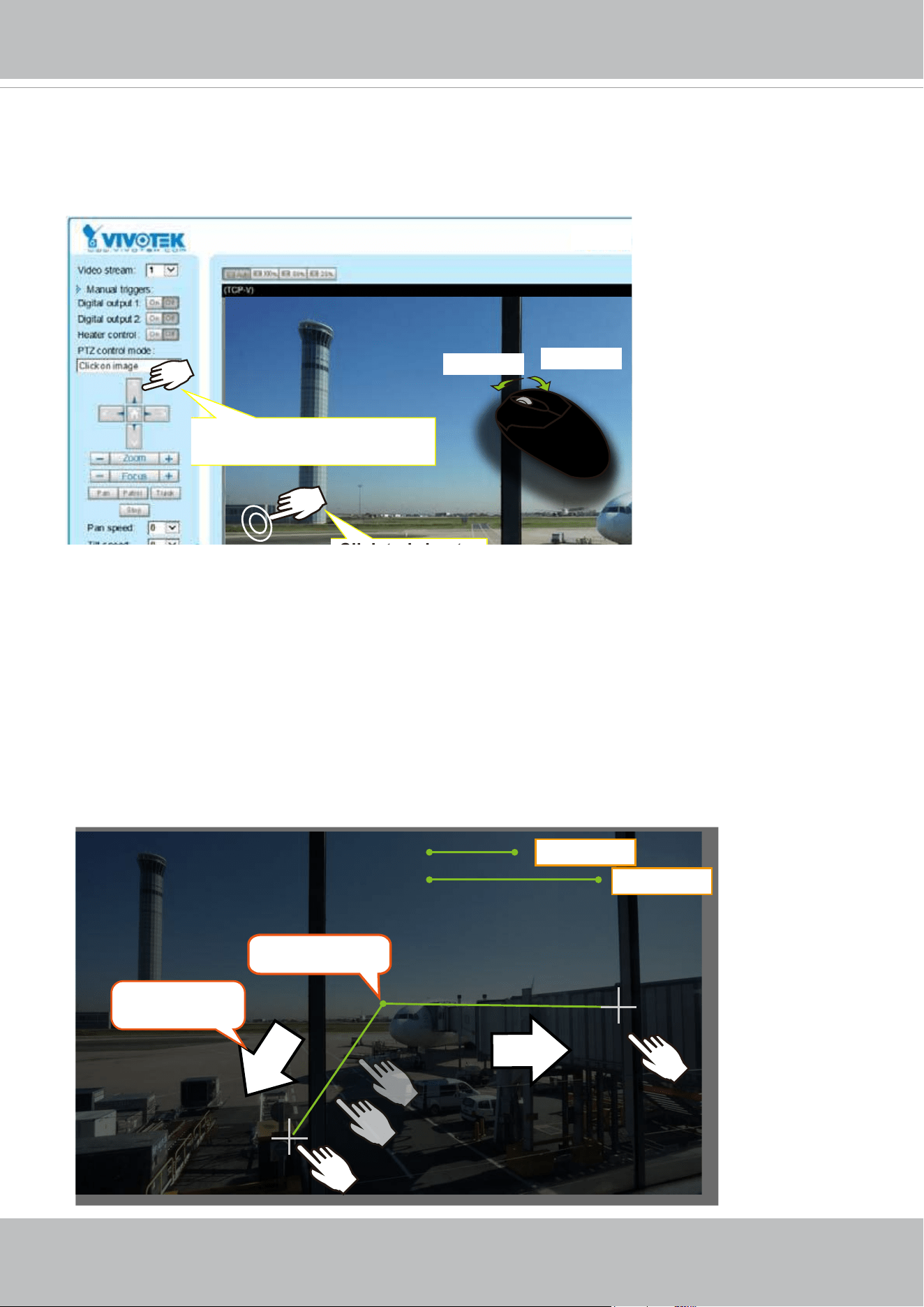
There are two different methodologies with the Click on image: Continuous and Click to move.
The Continuous move allows your screen control action to continue as long as you click and hold down
the left mouse button. For example, if you click on the left button on the PTZ control panel, the camera's
view should continuously rotate to the left until you release the button. The same applies to arrow keys,
Zoom, and Focus buttons on the PTZ panel. If you select Click to move, every single mouse click takes
effect for once without the ensuing move.
Use the drop-down menu to select a PTZ control mode.
VIVOTEK
User's Manual - 37
2. Joystick mode
The Joystick mode simulates joystick control using your mouse. Click and hold down the left mouse
button, and move your mouse target cursor to the direction you want. Drag towards the direction you
prefer, the lens will move to that direction. You can click and hold down the mouse button to continue
scanning.
The longer the track you drag away from the center, the faster the lens moves.
center point
Lens move
direction
Slower
Faster
1. Click on image
In addition to the use of a joystick, mouse control is also supported by the web session. You can click
on any spot on the screen to move camera's eld of view to that direction. To pan 360 degrees, you can
click and hold down the left mouse button when clicking a PTZ button. The same applies to arrow keys,
Zoom, and Focus buttons on the PTZ panel.
Note that if your screen control malfunctions, it is possible that the CPU of your current view station can
not cope with the HD video feeds or that an incompatibility issue occurred with the ActiveX control plug-
ins.
Zoom In
Zoom Out
Click and hold down the
button to continue turning
Click to bring to
VIVOTEK
38 - User's Manual
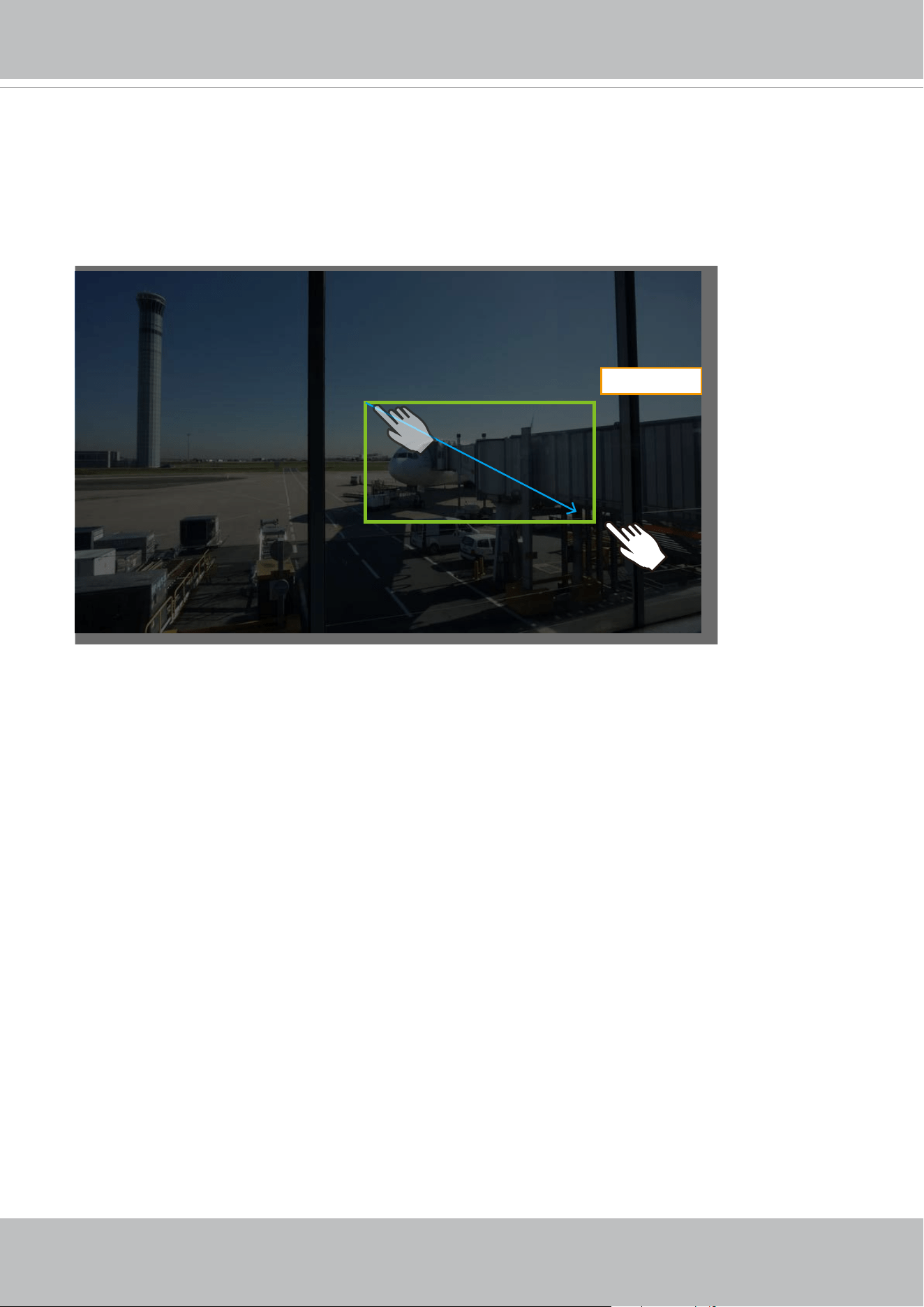
3. Area zoom
Click and drag across the screen to draw a rectangle. The camera will zoom in on that area. The smaller
the rectangle, the higher the zoom in ratio. The larger the rectangle, the smaller the zoom ratio.
To zoom out or return to the previous eld of view, click on the Zoom Out button, Home button, or any of
the preset PTZ positions.
Zoom in
VIVOTEK
User's Manual - 39
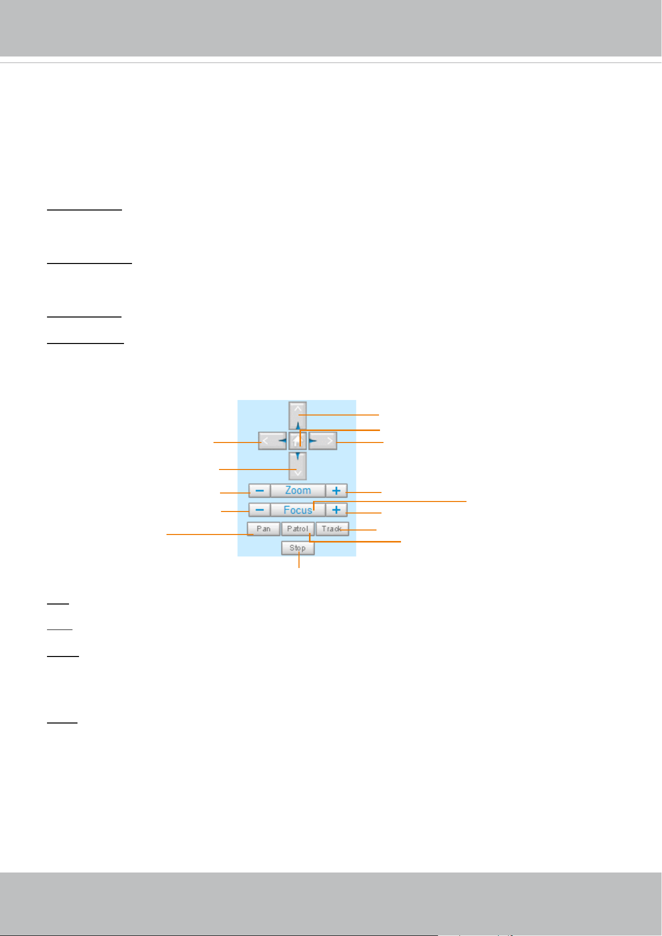
Left
Down
Zoom Out
Focus Near
Start to Auto Patrol
Start to Auto Pan
Stop Auto Panning/patrolling/tracking
Return to Home Position
Right
Up
Zoom In
Focus Far
Auto Focus
Auto Tracking
VIVOTEK INC. Logo
Click this logo to visit the VIVOTEK website.
Host Name
The host name can be customized to t your needs. For more information, please refer to System on page 50.
Camera Control Area
Video Stream: This Network Camera supports multiple streams (stream 1 ~ 4) simultaneously. You can
select either one for live viewing. For more information about multiple streams, please refer to page 71
for detailed information.
Manual triggers: Manual triggers can be turned on/off by users from the main page. The manual triggers
can be associated with the Event settings, and, as the result, can be used to perform recording actions,
sending notications, and so on. See Event settings on page 123.
Digital Output: Click to turn the digital output device on or off.
Heater control: This allows you to manually turn on or turn off the onboard heater.
PTZ Control Panel:
Pan: Click this button to start the auto pan (360° continuous rotation).
Stop: Click this button to stop the Auto Pan, Auto Patrol, and Auto Tracking functions.
Patrol: Once the Administrator has determined the list of preset positions (including the zoom-in action
on a particular position), click this button to command the camera to patrol among those positions on
the Patrol List. The Network Camera will patrol continuously. For more information, please refer to PTZ
control on page 114.
Track: Allows the camera to move along following the moving objects in the current eld of view. If you
observe an object of your interest, click this button to track the object. Note that this function does not
apply in an extremely crowded area, such as a market or sidewalk full of pedestrian activities. Constant
shift of tracked objects will decrease the usability of this feature.
Once started, you can use the Stop button to stop the current action. A click on the screen can also stop
the tracking action.
Another key concept is that the camera only detect movements within the current eld of view.
Please refer to PTZ > Auto tracking on page 121 and further for tracking conguration details.

VIVOTEK
40 - User's Manual
Pan /Tilt /Zoom /Focus speed: Adjust the speed of Pan/ Tilt/ Zoom/ Focus:
Note that mouse screen control is also supported. You can refer to page 114 for related information.
Conguration Area
Client Settings: Click this button to access the client setting page. For more information, please refer to
Client Settings on page 44.
Conguration: Click this button to access the conguration page of the Network Camera. It is suggested
that a password be applied to the Network Camera so that only the administrator can configure the
Network Camera. For more information, please refer to Conguration on page 49.
Language: Click this button to choose a language for the user interface. Language options are available
in: English, Deutsch, Español, Français, Italiano,
日本語
, Português,
簡体中文
, and
繁體中文
. You can
also change a language on the Conguration page; please refer to page 49.
Hide Button
You can click the hide button to hide the control panel or display the control panel.
Pan speed Tilt speed Zoom speed Focus speed
-5 -5 -5 -5 Slower
Faster
-4 -4 -4 -4
-3 -3 -3 -3
-2 -2 -2 -2
-1 -1 -1 -1
0 0 0 0
1 1 1 1
2 2 2 2
3 3 3 3
4 4 4 4
5 5 5 5
VIVOTEK
User's Manual - 41
Resize Buttons
:
Click the Auto button, the video cell will resize automatically to t the monitor.
Click 100% is to display the original homepage size.
Click 50% is to resize the homepage to 50% of its original size.
Click 25% is to resize the homepage to 25% of its original size.
Go to
If you have preset PTZ positions, these positions will be available in the Go to menu. Please refer to
page 114 for more information.
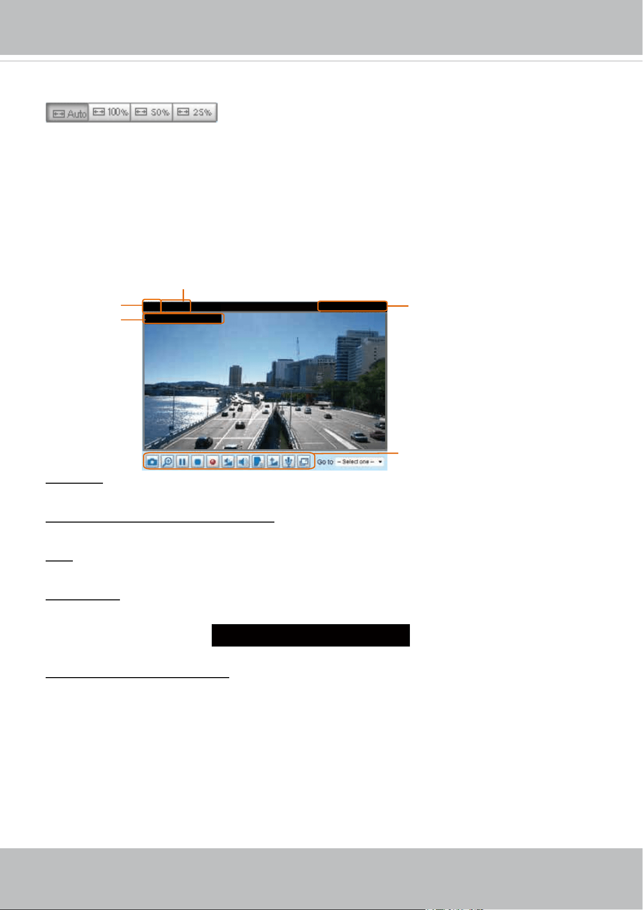
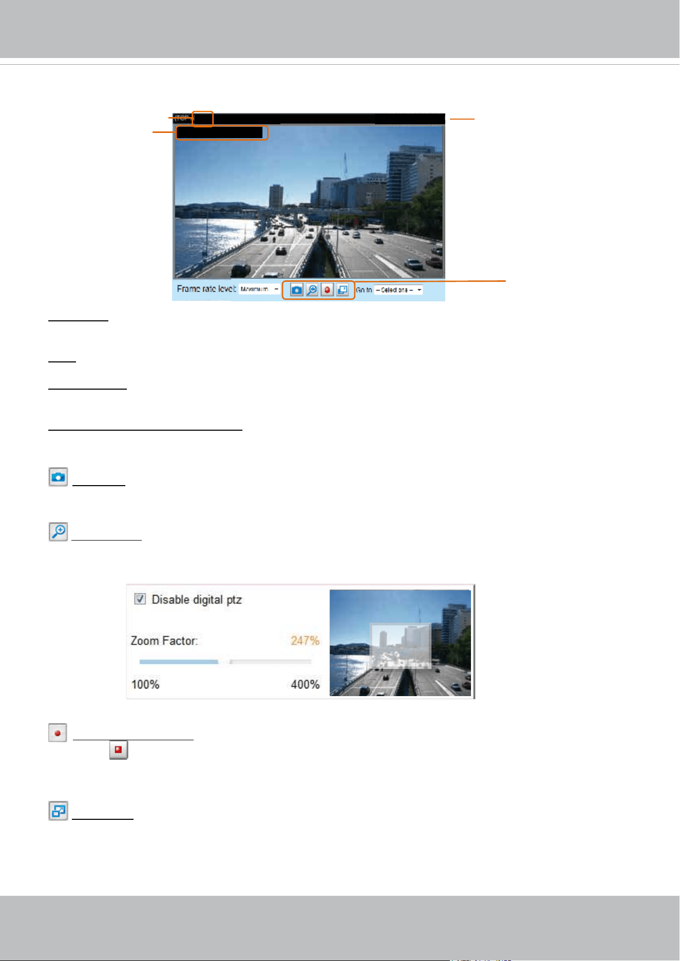
Live Video Window
■ The following window is displayed when the video mode is set to H.265 / H.264:
Video Title: The video title can be congured. For more information, please refer to Video settings on
page 60.
H.265/H.264 Protocol and Media Options: The transmission protocol and media options for H.265 /
H.264 video streaming. For further conguration, please refer to Client Settings on page 44.
Time: Display the current time. For further configuration, please refer to Media > Image > General
settings on page 60.
Title and Time: The video title and time can be stamped on the streaming video. For further conguration,
please refer to Media > Image > General settings on page 60. The zoom ratio is also displayed with the
title bar.
Video and Audio Control Buttons: Depending on the Network Camera model and Network Camera
conguration, some buttons may not be available.
2.0x Title 2016/03/05 10:39:08
Video 17:08:56 2016/03/10
Title and Time
2016/03/10 17:08:56
Time
Video and Audio Control Buttons
Video (TPC-AV)
H.265/H.264 Protocol and Media Options
Video Title
VIVOTEK
42 - User's Manual
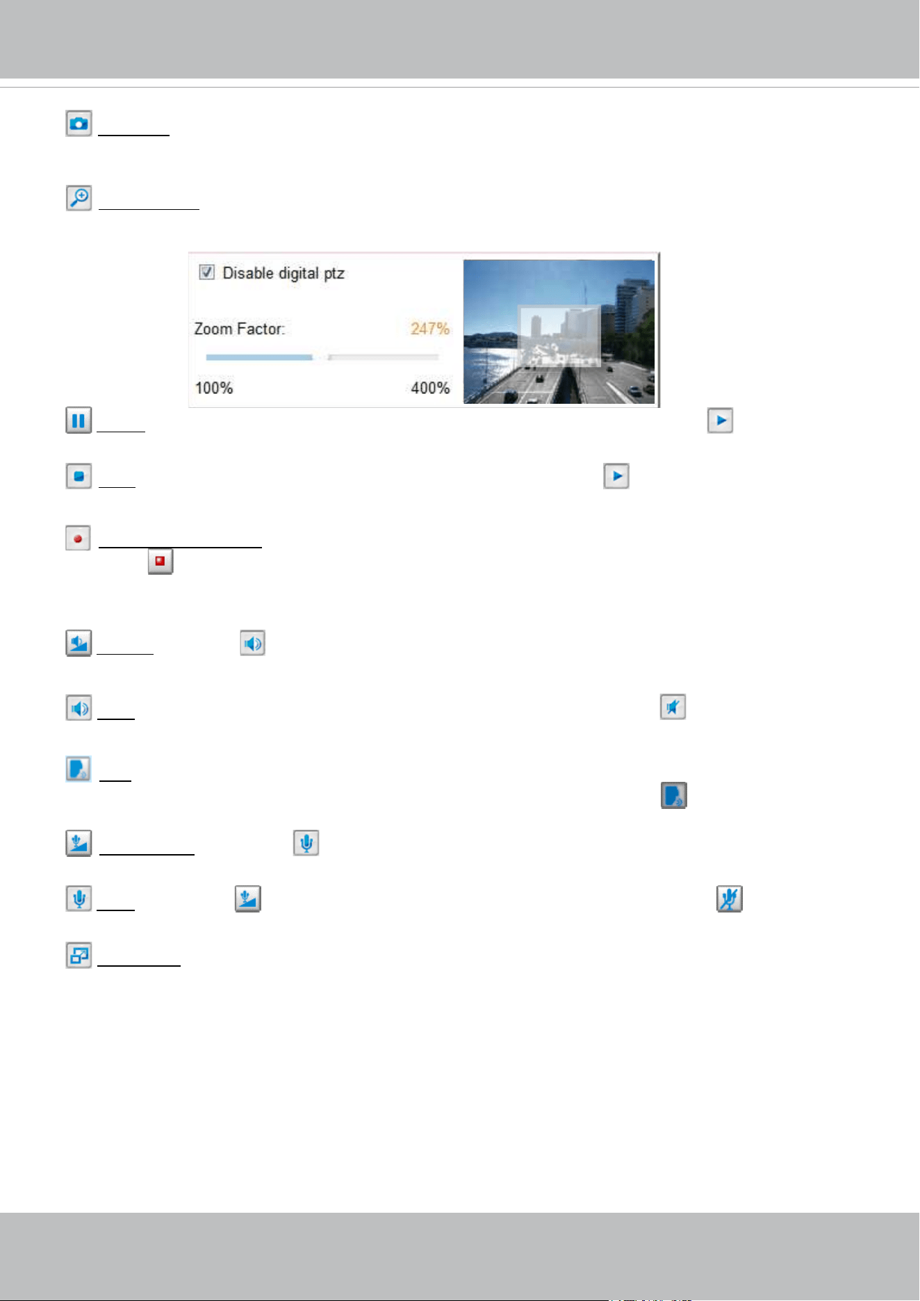
Snapshot: Click this button to capture and save still images. The captured images will be displayed
in a pop-up window. Right-click the image and choose Save Picture As to save it in JPEG (*.jpg) or BMP
(*.bmp) format.
Digital Zoom: Click and deselect the “Disable digital zoom” to enable the zoom operation. The
navigation screen indicates the part of the image being magnied. To control the zoom level, drag the
slider bar. To move to a different area you want to magnify, drag the navigation screen.
Pause: Pause the transmission of the streaming media. The button becomes the Resume button
after clicking the Pause button.
Stop: Stop the transmission of the streaming media. Click the Resume button to continue
transmission.
Start MP4 Recording: Click this button to record video clips in MP4 file format to your computer.
Press the
Stop MP4 Recording button to end recording. When you exit the web browser, video
recording stops accordingly. To specify the storage destination and le name, please refer to MP4 Saving
Options on page 45 for details.
Volume: When the Mute function is not activated, move the slider bar to adjust the volume on the
local computer.
Mute: Turn off the volume on the local computer. The button becomes the Audio On button after
clicking the Mute button.
Talk: Click this button to talk to people around the Network Camera. Audio will project from
the external speaker connected to the Network Camera. Click this button
again to end talking
transmission.
Mic Volume: When the Mute function is not activated, move the slider bar to adjust the
microphone volume on the local computer.
Mute: Turn off the Mic volume on the local computer. The button becomes the Mic On button
after clicking the Mute button.
Full Screen: Click this button to switch to full screen mode. Press the “Esc” key to switch back to normal
mode.
VIVOTEK
User's Manual - 43
■ The following window is displayed when the video mode is set to MJPEG:
Video Title: The video title can be congured. For more information, please refer to Media > Image on
page 60.
Time: Display the current time. For more information, please refer to Media > Image on page 60.
Title and Time: Video title and time can be stamped on the streaming video. For more information, please
refer to Media > Image on page 60
.
Video and Audio Control Buttons: Depending on the Network Camera model and Network Camera
conguration, some buttons may not be available.
Snapshot: Click this button to capture and save still images. The captured images will be displayed
in a pop-up window. Right-click the image and choose Save Picture As to save it in JPEG (*.jpg) or BMP
(*.bmp) format.
Digital Zoom: Click and uncheck “Disable digital zoom” to enable the zoom operation. The navigation
screen indicates the part of the image being magnied. To control the zoom level, drag the slider bar. To
move to a different area you want to magnify, drag the navigation screen.
Start MP4 Recording: Click this button to record video clips in MP4 file format to your computer.
Press the
Stop MP4 Recording button to end recording. When you exit the web browser, video
recording stops accordingly. To specify the storage destination and le name, please refer to MP4 Saving
Options on page 45 for details.
Full Screen: Click this button to switch to full screen mode. Press the “Esc” key to switch back to normal
mode.
Video 17:08:56 2016/03/10
Title and Time
2016/03/10 17:08:56
Time
Video (HTTP-V)
Video Title
Video Control Buttons
VIVOTEK
44 - User's Manual
Client Settings
This chapter explains how to select the stream transmission mode and saving options on the
local computer. When completed with the settings on this page, click Save on the page bottom
to enable the settings.
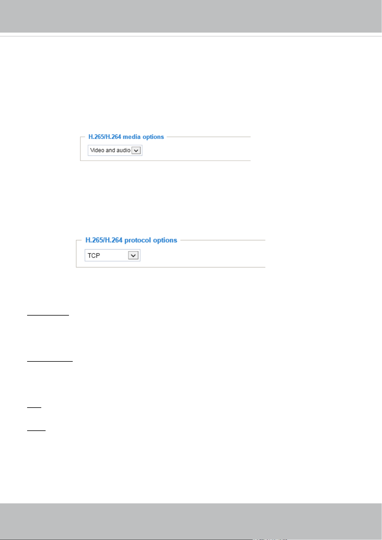
H.265/H.264 Media Options
Select to stream video or audio data or both. This is enabled only when the video mode is set to H.264 or
H.265.
H.265/H.264 Protocol Options
Depending on your network environment, there are four transmission modes of H.265 or H.264
streaming:
UDP unicast: This protocol allows for more real-time audio and video streams. However, network
packets may be lost due to network burst trafc and images may be broken. Activate UDP connection
when occasions require time-sensitive responses and the video quality is less important. Note that each
unicast client connecting to the server takes up additional bandwidth and the Network Camera allows up
to ten simultaneous accesses.
UDP multicast: This protocol allows multicast-enabled routers to forward network packets to all clients
requesting streaming media. This helps reduce the network transmission load of the Network Camera
while serving multiple clients at the same time. Note that to utilize this feature, the Network Camera must
be configured to enable multicast streaming at the same time. For more information, please refer to
RTSP Streaming on page 89.
TCP: This protocol guarantees the complete delivery of streaming data and thus provides better video
quality. The downside of this protocol is that its real-time effect is not as good as that of the UDP protocol.
HTTP: This protocol allows the same quality as TCP protocol without needing to open specic ports for
streaming under some network environments. Users inside a firewall can utilize this protocol to allow
streaming data through.
VIVOTEK
User's Manual - 45
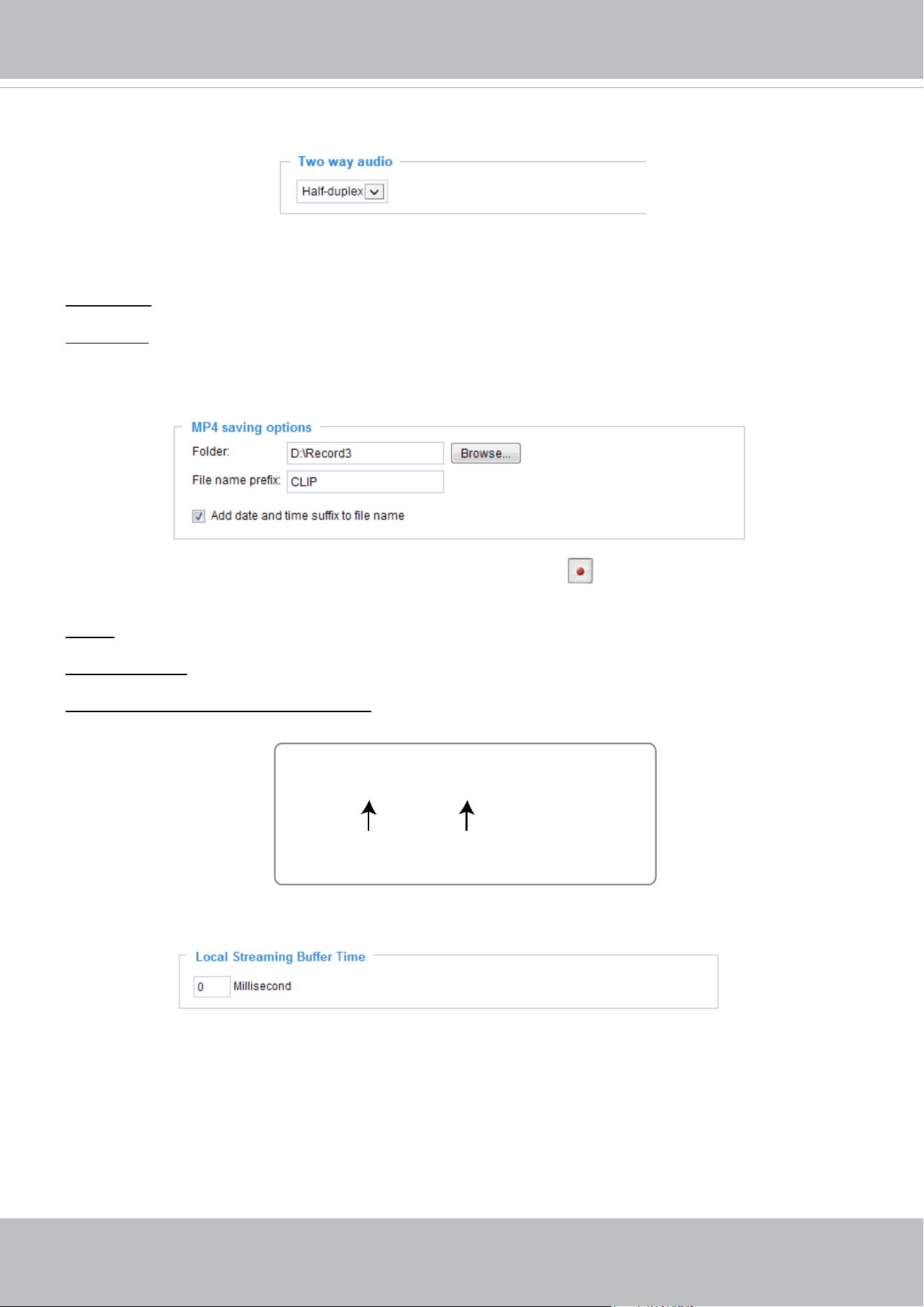
Two way audio
Half duplex: Audio is transmitted from one direction at a time, e.g., from a PC holding a web console with
the camera.
Full duplex: Audio is transmitted in both directions simultaneously.
MP4 Saving Options
Users can record live video as they are watching it by clicking the button - Start MP4 Recording - on
the main page. Here, you can specify the storage destination and le name.
Folder: Specify a storage destination for the recorded video les.
File name prex: Enter the text that will be appended to the front of the video le name.
Add date and time sufx to the le name: Select this option to append the date and time to the end of the
le name of the recorded videos.
Local Streaming Buffer Time
In a busy network, fluctuations in available bandwidth can occur. Video streaming may lag and may
not proceed very smoothly. If you enable this option, video streams from the camera will be temporarily
stored on the computer’s cache memory for a configurable period of time (seconds or milliseconds)
before being played on a web session. This will help you see the streaming more smoothly. If you enter
3,000 Millisecond, the streaming will delay for 3 seconds.
CLIP_20180328-180853
Date and time sufx
The format is: YYYYMMDD_HHMMSS
File name prex
VIVOTEK
46 - User's Manual
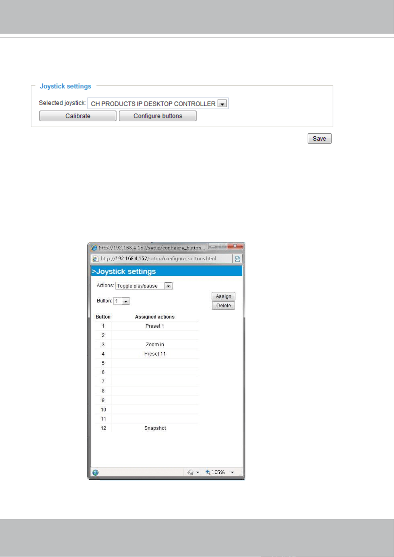
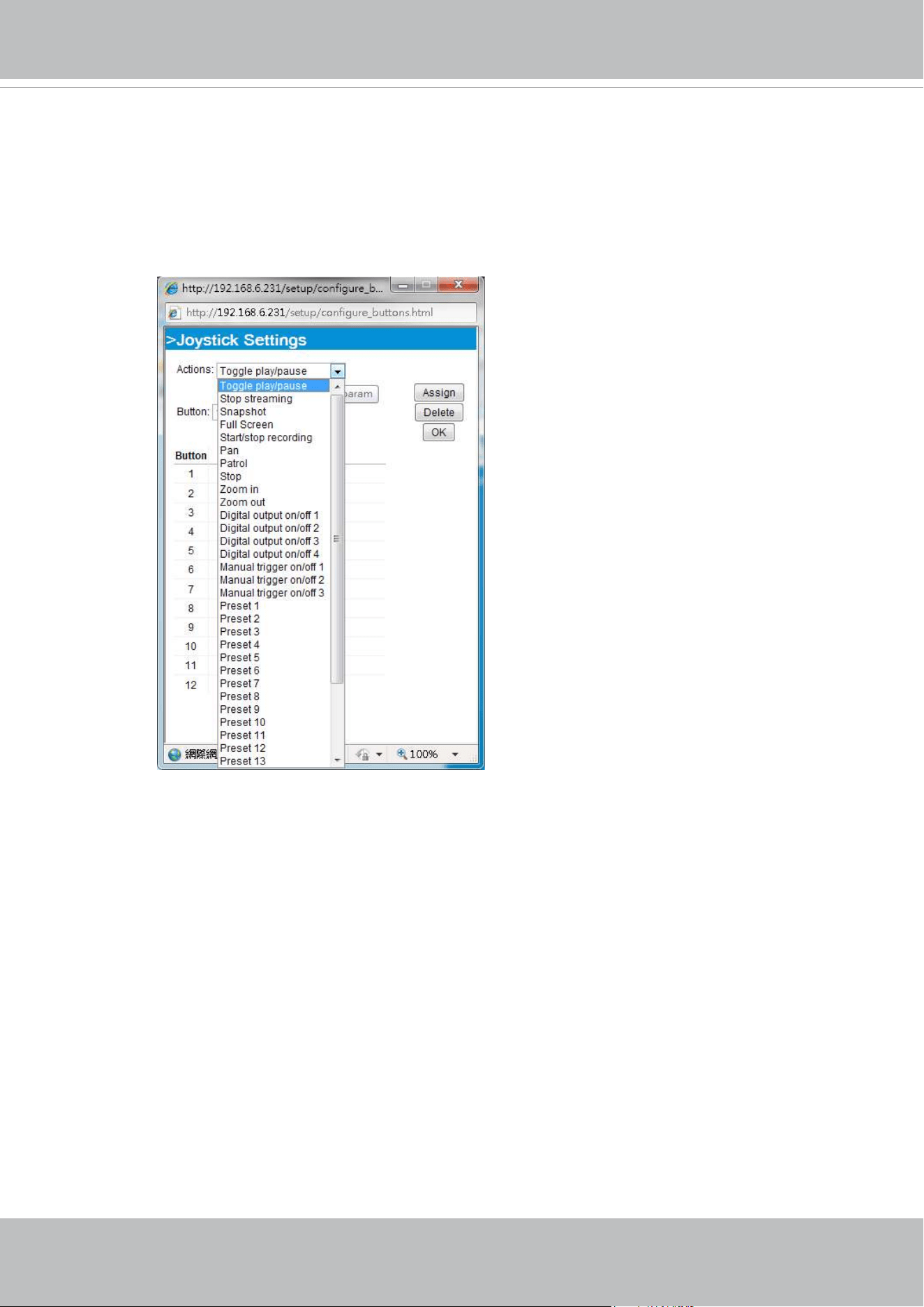
Joystick Settings
Enable Joystick
Connect to the USB plug of the joystick to a USB port on your management computer. Once a USB
joystick is connected, the related joystick conguration will be available on the Client settings window.
The joystick should work properly without installing any other driver or software.
Then you can begin to congure the joystick settings of connected devices. Please follow the instructions
below to enable joystick settings.
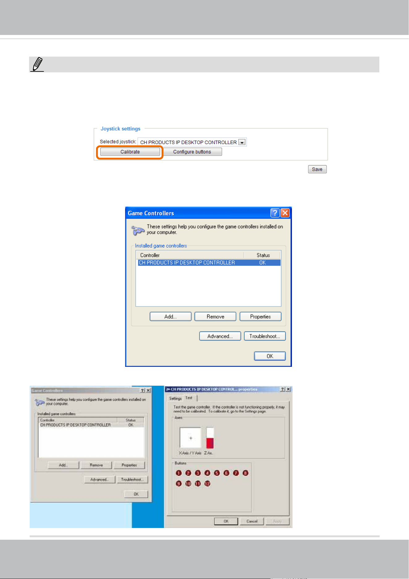
1. Click on the Congure buttons button. If your joystick is working properly, it will be displayed on the
drop-down list.
VIVOTEK
User's Manual - 47
Buttons Conguration
In the Joystick Settings window, you can use the combinations of pull-down menus, Actions and Button
number, to assign joystick buttons with different functions. The number of buttons may differ from the
joystick you attached.
Please follow the steps below to congure your joystick buttons:
1. Select the number of the button you want to congure from its pull-down list.
For example: Assign Preset 1 (move to preset 1 position) to Button 1.
2. Select an action from the Actions menu. Click Assign to associate the button with an action.
3. Your conguration will be automatically saved.
4.
To disable an assignment, select the number of a button, and then click the Delete button. The
associated action will then be cleared.
5. Repeat the above process to assign actions to other buttons.
When done, simply close the conguration
window.
VIVOTEK
48 - User's Manual
• If you want to assign Preset actions to your joystick, the PTZ preset locations should be congured in
advance.
• If your joystick is not working properly, it may need to be calibrated. Click the Calibrate button to open
the Game Controllers window located in Microsoft Windows control panel and follow the instructions for
trouble shooting.
NOTE:
• The joystick will appear in the Game Controllers list in the Windows Control panel. If you want to check
out for your devices, go to the following page: Start -> Control Panel -> Game Controllers.
• Follow the onscreen instructions to calibrate your joystick.
VIVOTEK
User's Manual - 49
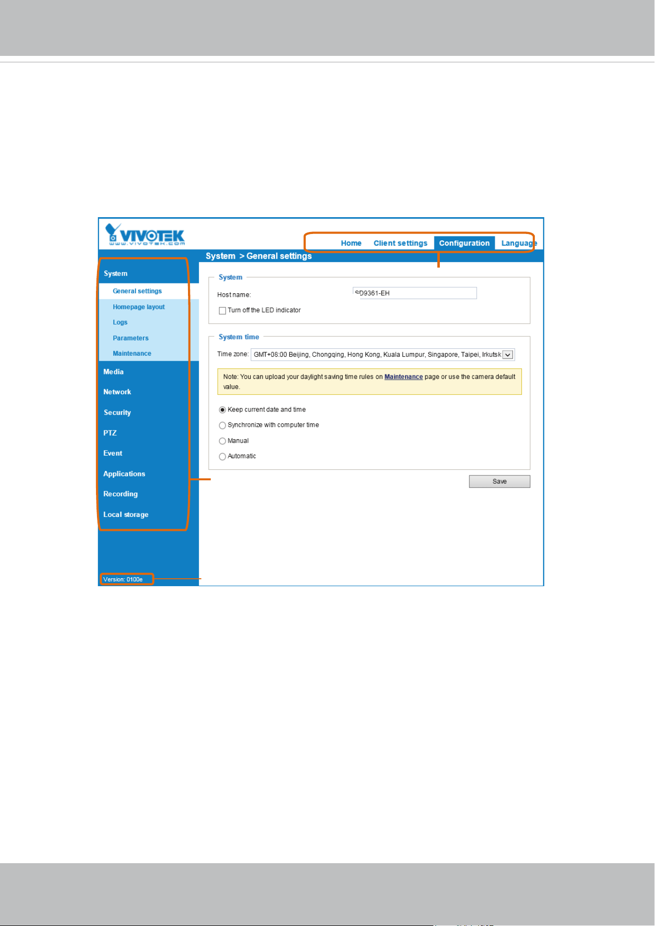
Conguration
Click Configuration on the main page to enter the camera setting pages. Note that only
Administrators can access the configuration page. Please refer to page 100 Security > User
Account for how to congure access rights for different users.
Configuration List
Firmware Version
Navigation Area
Each function on the conguration list will be explained in the following sections.
Navigation Area provides an instant switch among Home page (the monitoring page for live viewing),
Conguration page, and multi-language selection.
VIVOTEK
50 - User's Manual
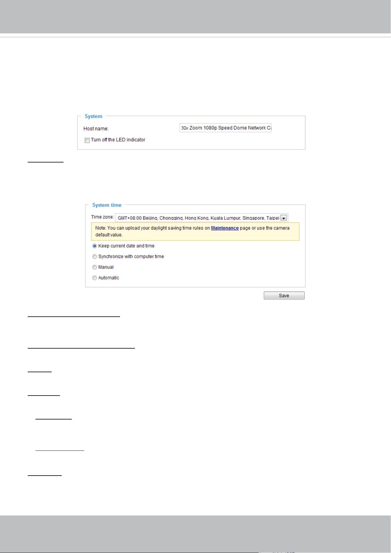
System > General settings
This section explains how to congure the basic settings for the Network Camera, such as the
host name and system time. It is composed of the following two columns: System and System
Time.
System
Host name: Enter a desired name for the Network Camera. The text will be displayed at the top of the
main page.
System time
Keep current date and time: Select this option to preserve the current date and time of the Network
Camera. The Network Camera’s internal real-time clock maintains the date and time even when the
power of the system is turned off.
Synchronize with computer time: Select this option to synchronize the date and time of the Network
Camera with the local computer. The read-only date and time of the PC is displayed as updated.
Manual: The administrator can enter the date and time manually. Note that the date and time format are
[yyyy/mm/dd] and [hh:mm:ss].
Automatic: The Network Time Protocol is a protocol which synchronizes computer clocks by periodically
querying an NTP Server.
NTP server: Assign the IP address or domain name of an established time server. Leaving the text box
blank connects the Network Camera to the default time servers. The precondition is that your camera
must have access to the Internet.
Update interval: Select to update the time using the NTP server on an hourly, daily, weekly, or monthly
basis.
Time zone : Select the appropriate time zone from the list. If you want to upload Daylight Savings Time
rules, please refer to System > Maintenance > Import/ Export les on page 57 for details.
When nished with the settings on this page, click Save at the bottom of the page to enable the settings.
VIVOTEK
User's Manual - 51
System > Homepage layout
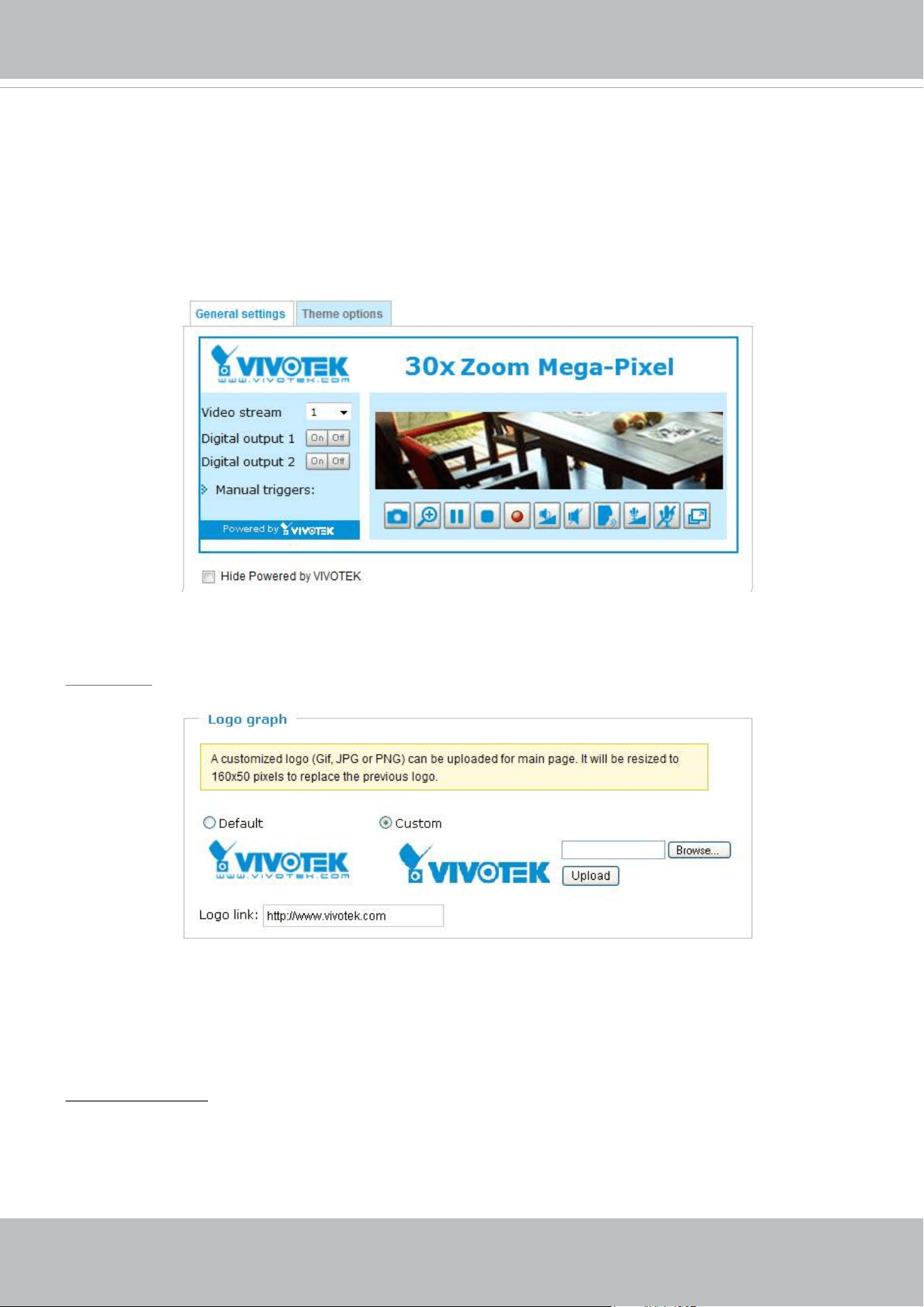
This section explains how to set up your own customized homepage layout.
General settings
This column shows the settings of your hompage layout. You can manually select the background and
font colors in Theme Options (the second tab on this page). The settings will be displayed automatically
in this Preview eld. The following shows the homepage using the default settings:
■ Hide Powered by VIVOTEK: If you check this item, such wording will be removed from the homepage.
Logo graph
Here you can change the logo at the top of your homepage.
Follow the steps below to upload a new logo:
1. Click Custom and the Browse eld will appear.
2. Select a logo from your les.
3. Click Upload to replace the existing logo with a new one.
4. Enter a website link if necessary.
5. Click Save to enable the settings.
Customized button
Deselect the checkbox if you do not need the Manual trigger buttons on the main page.
VIVOTEK
52 - User's Manual
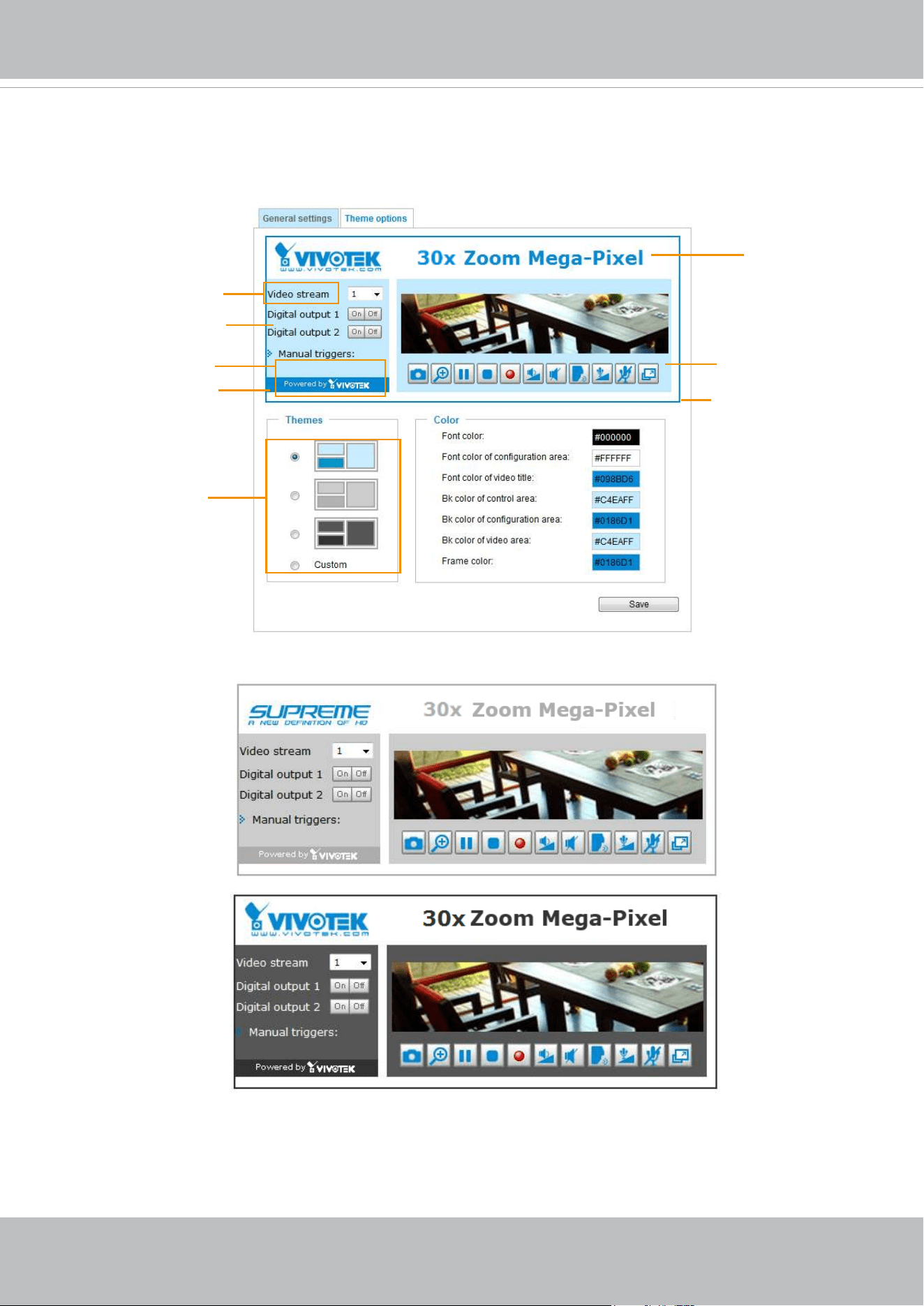
Theme Options
Here you can change the color of your homepage layout. There are three types of preset patterns for you
to choose from. The new layout will simultaneously appear in the Preview led. Click Save to enable the
settings.
Font Color of the
Video Title
Background Color of
the Video Area
Frame Color
Font Color
Background Color of the
Control Area
Font Color of the
Configuration Area
Background Color of the
Configuration Area
Preset patterns
VIVOTEK
User's Manual - 53
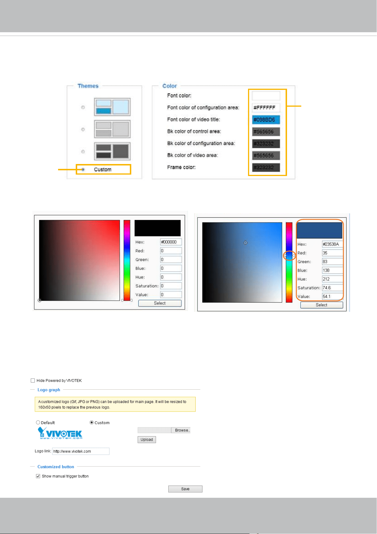
■ Follow the steps below to set up the customed homepage:
1. Click Custom on the left column.
2. A double-click on the color selection area (the right hand side column) will bring up a color palette
window.
3. The palette window will pop up as shown below.
4. Drag the slider bar and click on the left square to select a desired color.
5. The selected color will be displayed in the corresponding elds and in the Preview column.
6. Click Save to enable the settings.
Below are the options for system integrators or VARs. You can use the checkboxes to replace
VIVOTEK’s company logo, the embedded website address or the slogan “Powered by VIVOTEK.“ When
done, use the Save button to complete the conguration.
1
2
3
4
Color Selector
Custom
Pattern
VIVOTEK
54 - User's Manual
System > Logs
This section explains how to configure the Network Camera to send the system log to the
remote server as backup.
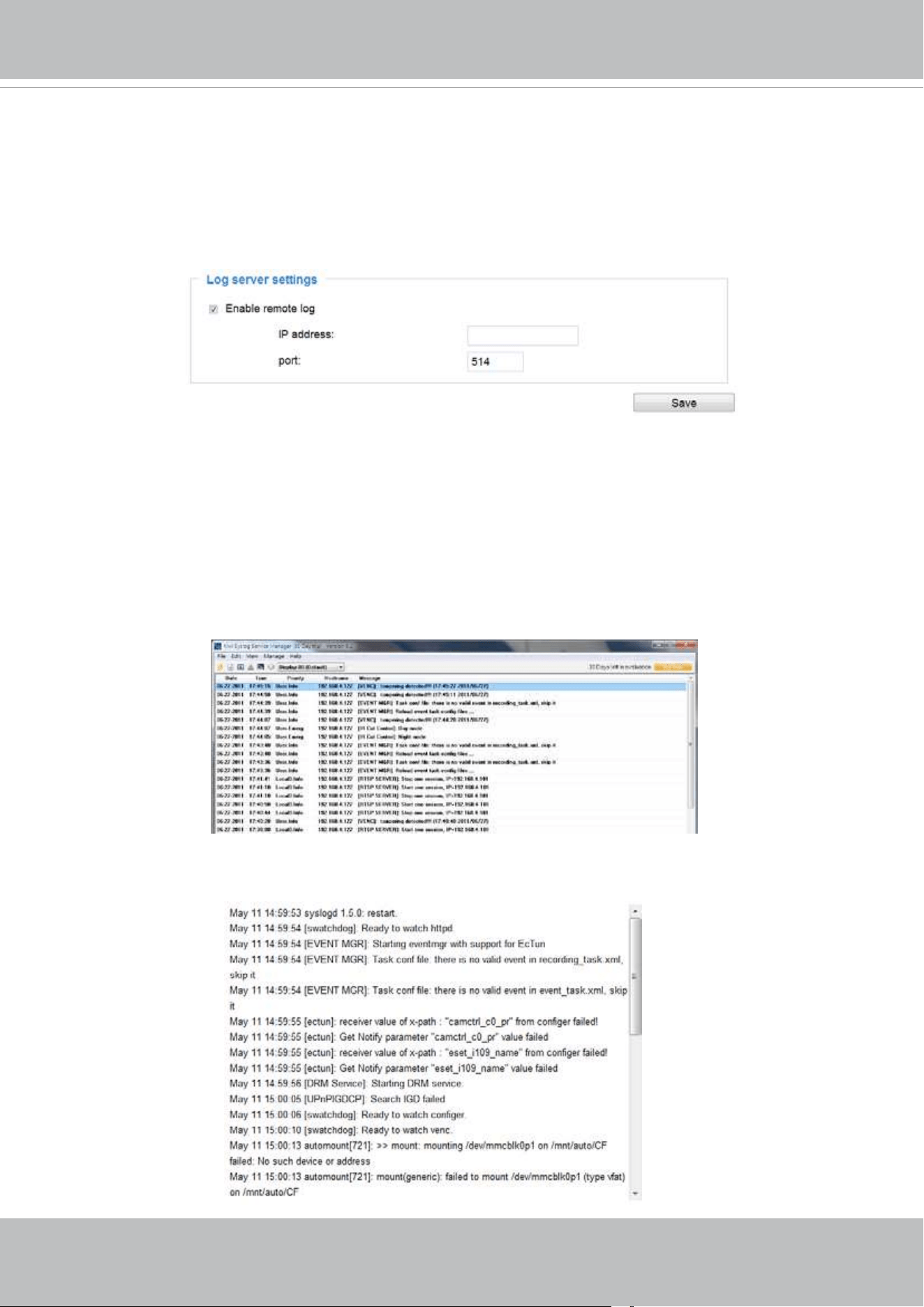
Log server settings
Follow the steps below to set up the remote log:
1. Select Enable remote log.
2. In the IP address text box, enter the IP address of the remote server.
2. In the port text box, enter the port number of the remote server.
3. When completed, click Save to enable the setting.
You can congure the Network Camera to send the system log le to a remote server as a log backup.
Before utilizing this feature, it is suggested that the user install a log-recording tool to receive system log
messages from the Network Camera. An example is Kiwi Syslog Daemon. Visit
http://www.kiwisyslog.
com/kiwi-syslog-daemon-overview/
.
System log
This column displays the system log in a chronological order. The system log is stored in the Network
Camera’s buffer area and will be overwritten when the number of events reaches a preset limit.
VIVOTEK
User's Manual - 55
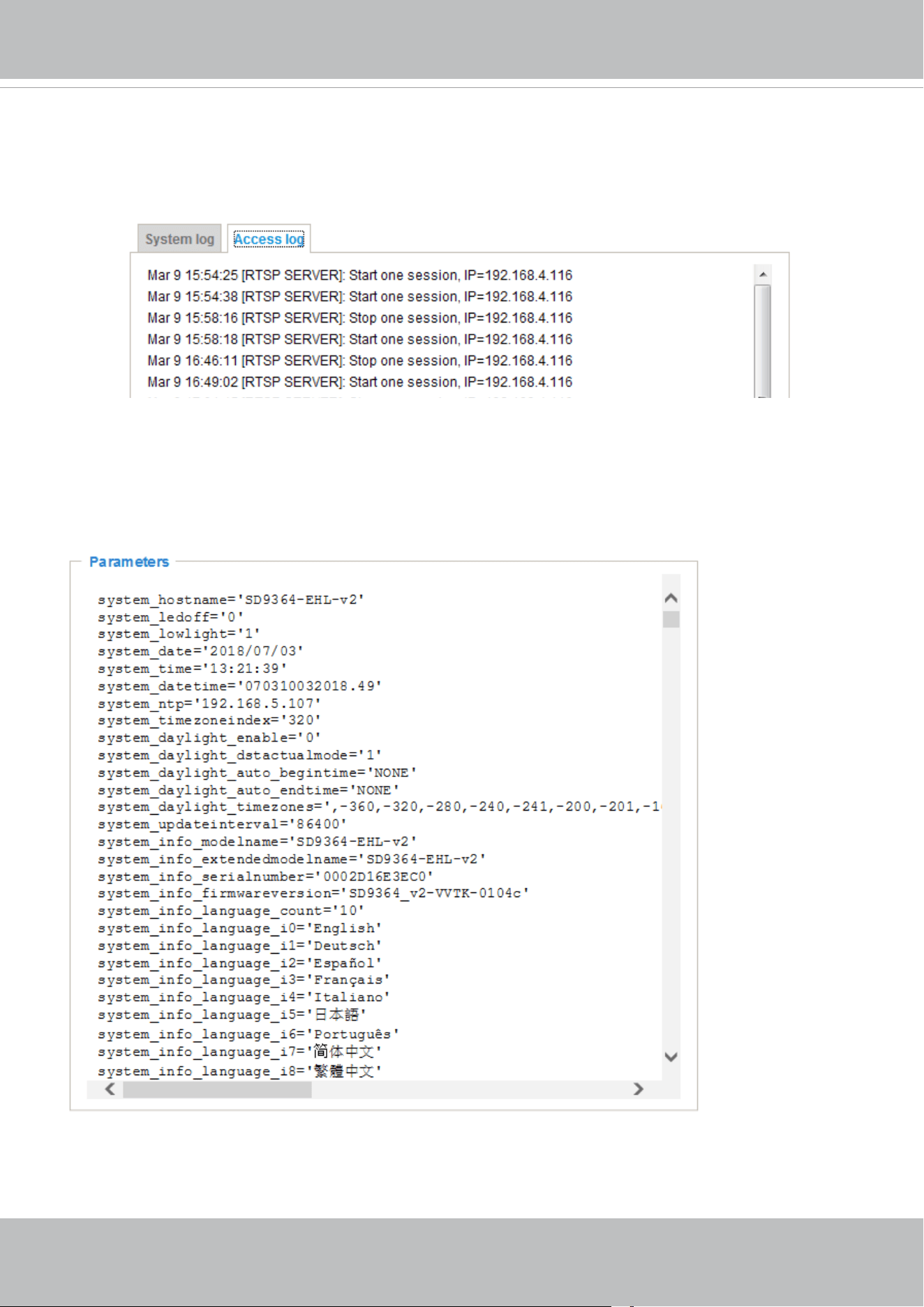
Access log
Access log displays the access time and IP address of all viewers (including operators and
administrators) in a chronological order. The access log is stored in the Network Camera’s buffer area
and will be overwritten when reaching a certain limit.
System > Parameters
The View Parameters page lists the entire system’s parameters in an alphabetical order. If you
need technical assistance, please provide the information listed on this page.
VIVOTEK
56 - User's Manual
System > Maintenance
This chapter explains how to restore the Network Camera to factory default, reboot, upgrade
rmware version, etc.
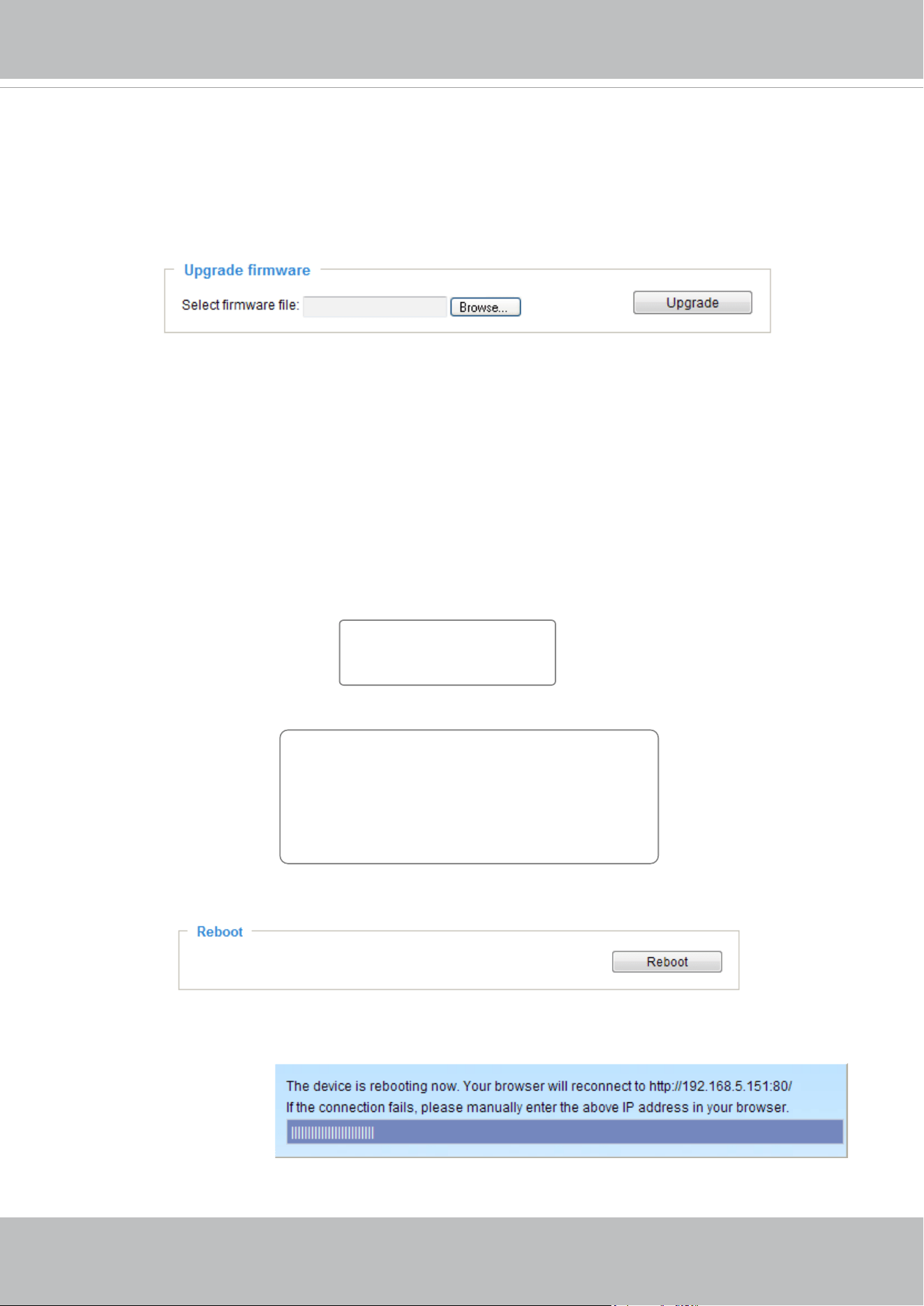
General settings > Upgrade rmware
This feature allows you to upgrade the firmware of your Network Camera. It takes a few minutes to
complete the process.
Note: Do not power off the Network Camera during the upgrade!
Follow the steps below to upgrade the rmware:
1. Download the latest rmware le from the VIVOTEK website. The le is in .pkg le format.
2. Click Browse… and specify the rmware le.
3. Click Upgrade. The Network Camera starts to upgrade and will reboot automatically when the upgrade
completes.
If the upgrade is successful, you will see “Reboot system now!! This connection will close”. After that,
refresh the management session with the Network Camera.
The following message is displayed when the upgrade has succeeded.
The following message is displayed when you have selected an incorrect rmware le.
General settings > Reboot
This feature allows you to reboot the Network Camera, which takes about one minute to complete. When
completed, the live video page will be displayed in your browser. The following message will be displayed
during the reboot process.
If the connection fails after rebooting, manually enter the IP address of the Network Camera in the
address eld to resume the connection.
Starting firmware upgrade...
Do not power down the server during the upgrade.
The server will restart automatically after the upgrade is
completed.
This will take about 1 - 5 minutes.
Wrong PKG file format
Unpack fail
Reboot system now!!
This connection will close.
VIVOTEK
User's Manual - 57
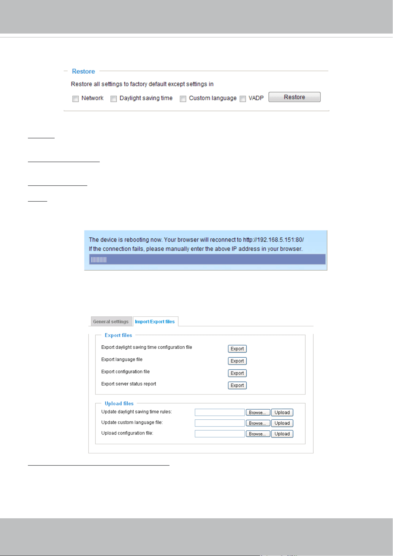
General settings > Restore
This feature allows you to restore the Network Camera’s factory defaults.
Network: Select this option to retain the Network Type settings (please refer to Network Type on page
80).
Daylight Saving Time: Select this option to retain the Daylight Saving Time settings (please refer to
Import/Export les below on this page).
Custom Language: Select this option to retain the Custom Language settings.
VADP: Retain the VADP modules (3rd-party software stored on the SD card) and related settings.
If none of the options is selected, all settings will be restored to factory default. The following message is
displayed during the restoring process.
Import/Export les
This feature allows you to Export / Update daylight saving time rules, custom language file, and
conguration le.
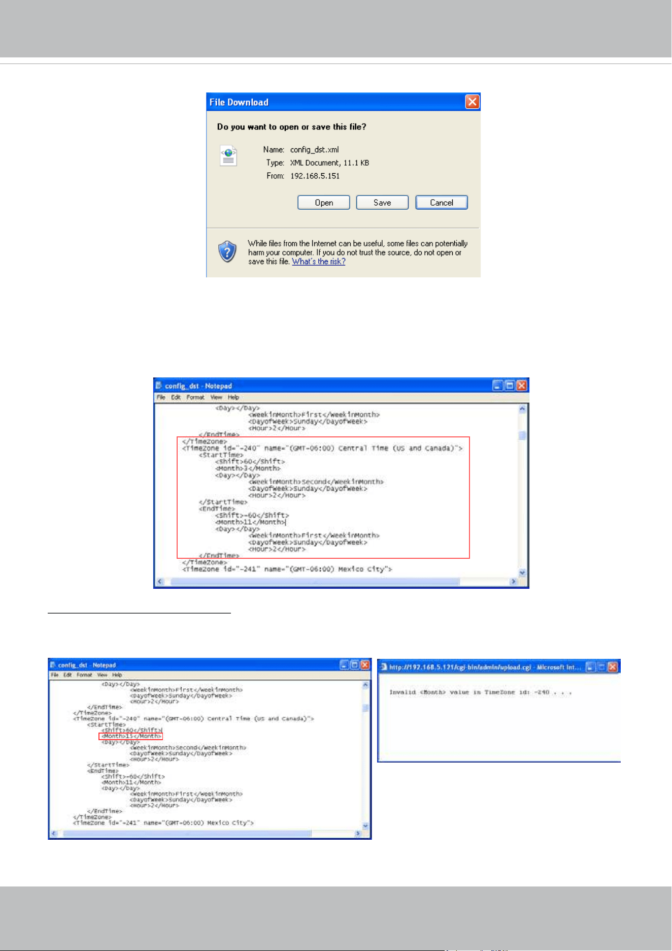
Export daylight saving time conguration le: Click to set the start and end time of DST.
Follow the steps below to export:
1. In the Export les column, click Export to export the daylight saving time conguration le from the
Network Camera.
2. A le download dialog will pop up as shown below. Click Open to review the XML le or click Save to
store the le for editing.
VIVOTEK
58 - User's Manual
3. Open and edit the le using Microsoft
®
Notepad and locate your time zone in the strings; set the start
and end time of DST. When completed, save the le.
In the example below, DST begins each year at 2:00 a.m. on the second Sunday in March and ends at
2:00 a.m. on the rst Sunday in November.
Update daylight saving time rules: Click Browse… and specify the XML le to update.
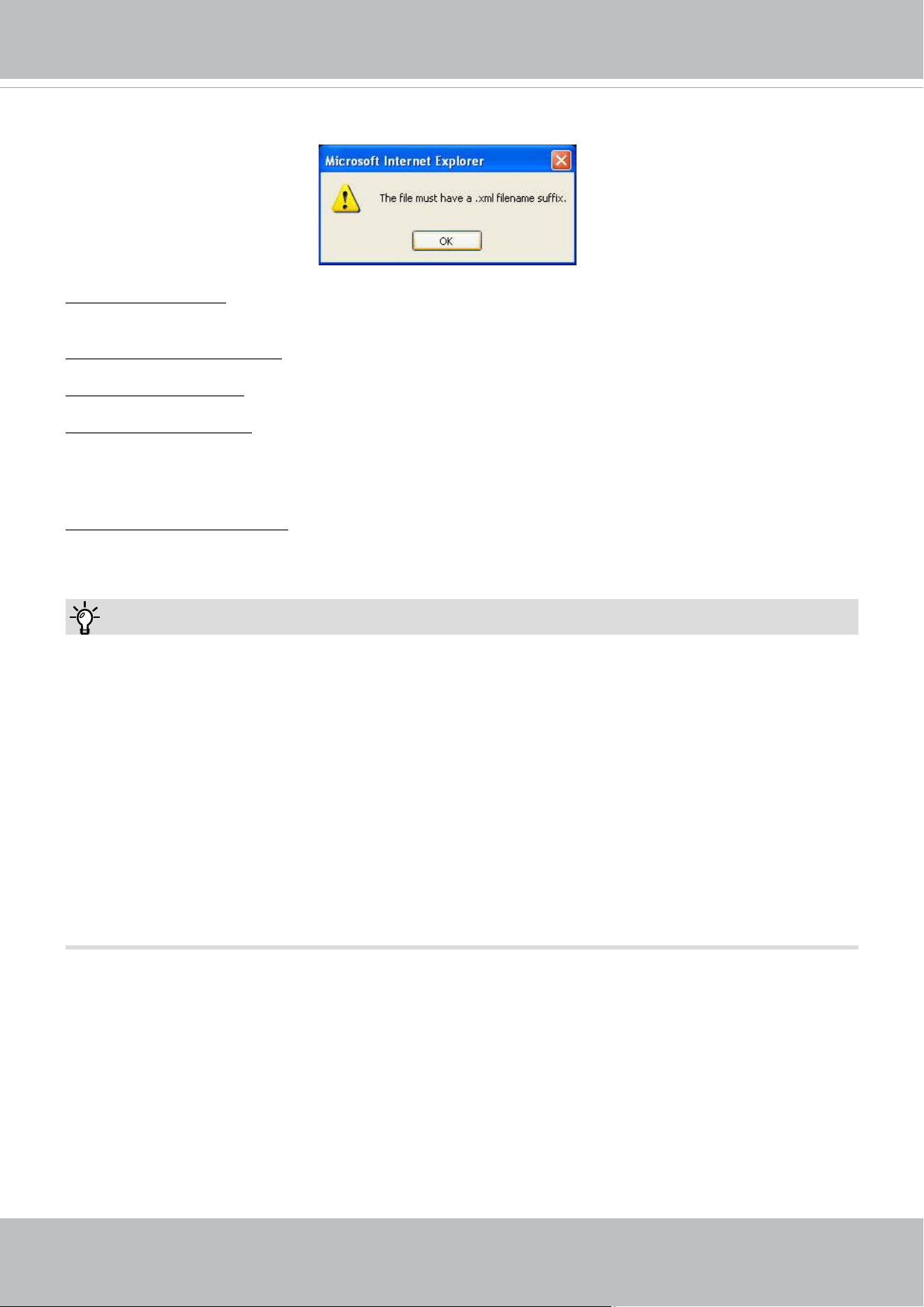
If the incorrect date and time are assigned, you will see the following warning message when uploading
the le to the Network Camera.
VIVOTEK
User's Manual - 59
The following message is displayed when attempting to upload an incorrect le format.
Export language file: Click to export language strings. VIVOTEK provides nine languages: English,
Deutsch, Español, Français, Italiano,
日本語,
Português,
簡体中文
, and
繁體中文
.
Update custom language le: Click Browse… and specify your own custom language le to upload.
Export conguration le: Click to export all parameters for the device and user-dened scripts.
Update conguration le: Click Browse… to update a conguration le. Please note that the model and
rmware version of the device should be identical to those specied for the conguration le. If you have
set up a xed IP or other special settings for your device, it is not suggested to update a conguration
le.
Export server status report: Click to export the current server status report, such as time, logs,
parameters, process status, memory status, le system status, network status, kernel message..., and so
on.
Tips:
• If a firmware upgrade is accidentally disrupted, say, by a power outage, you still have a last resort
method to restore normal operation. See the following for how to bring the camera back to work:
Applicable scenario:
(1) Power disconnected during rmware upgrade.
(2) Unknown reason causing abnormal LED status, and a Restore cannot recover normal working
condition.
You can use the following methods to activate the camera with its backup rmware:
(1) Press and hold down the reset button for at least one minute.
(2) Power on the camera until the Red LED blinks rapidly.
(3) After boot up, the firmware should return to the previous version before the camera hanged.
(The procedure should take 5 to 10 minutes, longer than the normal boot-up process). When this
process is completed, the LED status should return to normal.
VIVOTEK
60 - User's Manual
Media > Image
This section explains how to configure the image settings of the Network Camera. It is
composed of the following four columns: General settings, IR control, Image settings, Exposure,
and Privacy mask.
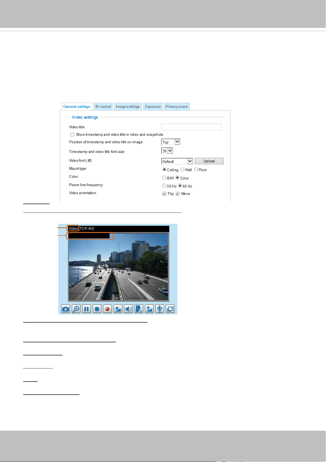
General settings
Video title
Show_timestamp and video title in videos_and_snapshots: Enter a name that will be displayed on the
title bar of the live video as the picture shown below.
Video Title
Title and Time
Video 17:08:56 2016/03/09
2016/03/09 17:08:56
Position of timestamp and video title on image: Select to display time stamp and video title on the top or
at the bottom of the video stream.
Timestamp and video title font size: Select the font size for the time stamp and title.
Video font (.ttf): You can select a True Type font le for the display of textual messages on video.
Mount type: Select Ceiling, Wall, or Floor to determine the default imaging orientation of the camera.
Color: Select to display color or black/white video streams.
Power line frequency: Set the power line frequency consistent with local utility settings to eliminate image
flickering associated with fluorescent lights. Note that after the power line frequency is changed, you
must disconnect and reconnect the power cord of the Network Camera in order for the new setting to
take effect.
VIVOTEK
User's Manual - 61
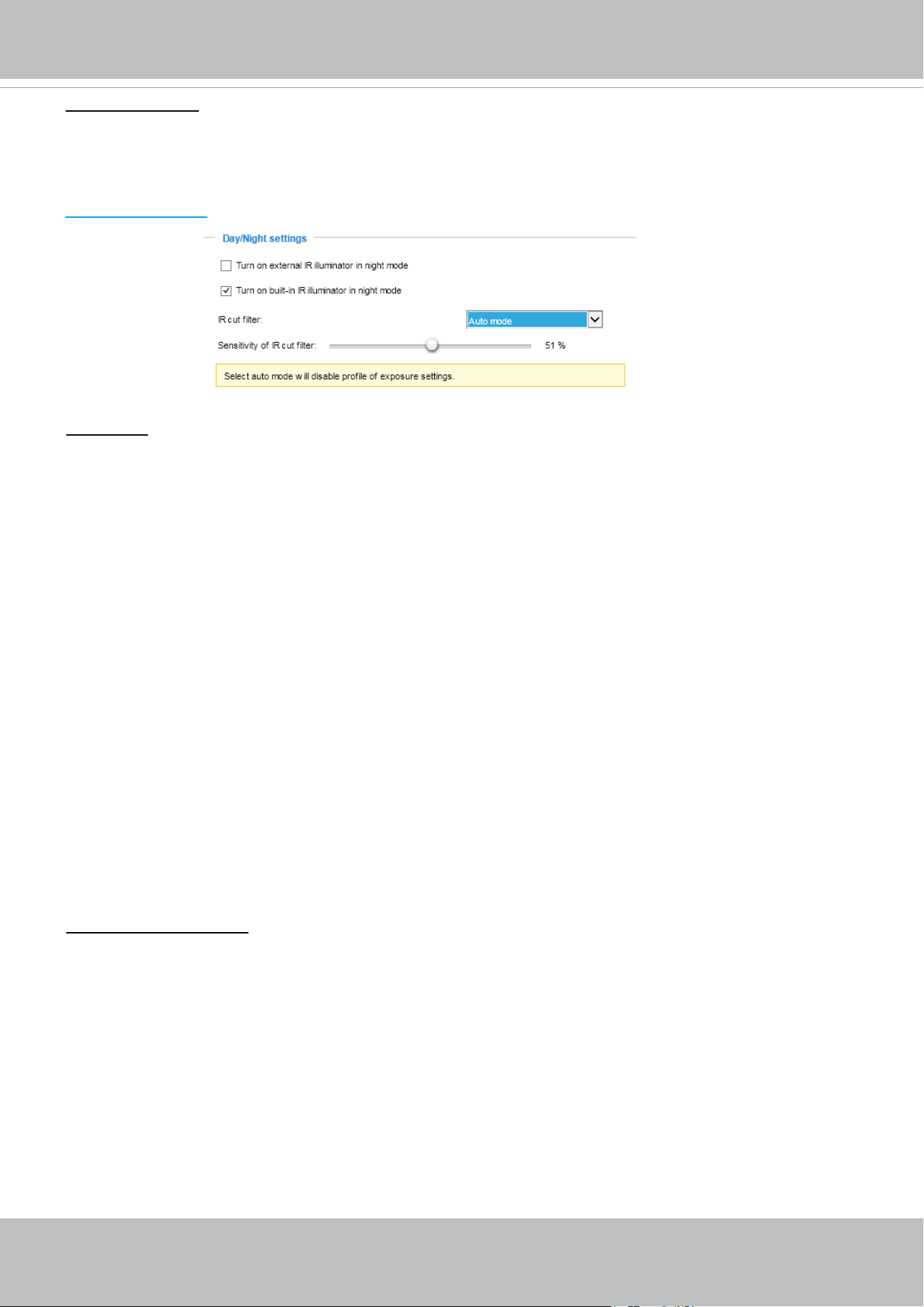
Day/Night Settings
IR cut lter
With a removable IR-cut filter, this Network Camera can automatically remove the filter to let IR light
enter the light sensor during low light conditions.
■ Auto mode
The Network Camera automatically removes the lter by judging the level of ambient light.
■ Day mode
In day mode, the Network Camera switches on the IR cut lter at all times to block infrared light from
reaching the sensor so that the colors will not be distorted.
■ Night mode
In night mode, the Network Camera switches off the IR cut lter at all times for the sensor to accept
infrared light, thus helping to improve low light sensitivity.
■ Synchronize with digital input
The Network Camera automatically removes the IR cut filter when a Digital Input is triggerred. For
example, the digital input can come from a housing that is equipped with IR illumination and control
circuits such as VIVOTEK’s AM-214.
■ Schedule mode
The Network Camera switches between day mode and night mode based on a specied schedule.
Enter the start and end time for day mode. Note that the time format is [hh:mm] and is expressed in
24-hour clock time. By default, the start and end time of day mode are set to 07:00 and 18:00.
Sensitivity of IR cut lter
Tune the responsiveness of the IR cut lter to lighting conditions by the percentage. Judging by the light
level, contrast, and color hue, the light sensing algorithms enables the switch between day and night
modes. The actual lighting conditions can vary when the lens modules zooms in/out to a target area.
When completed with the settings on this page, click Save to enable the settings.
Video orientation: Flip - vertically reflect the display of the live video; Mirror - horizontally reflect the
display of the live video. Change the settings if the Network Camera is installed in a different orientation
(which is rare for a speed dome) to correct the image orientation.

VIVOTEK
62 - User's Manual
IR control
Turn on built-in IR illuminator in night mode
Select this to turn on the built-in IR illuminator when the camera detects low light condition and enters the
night mode. Default is selected.
Turn on external IR illuminator in night mode
Select this to turn on the external IR illuminator when the camera detects low light condition and enters
the night mode. A Digital Output connection to external IR is needed.
VIVOTEK
User's Manual - 63
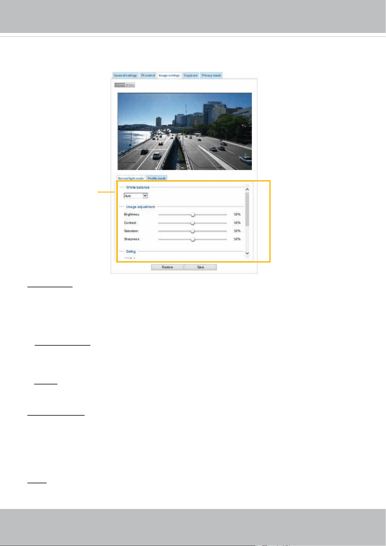
Image settings
On this page, you can tune the White balance and Image adjustment settings.
White balance: Adjust the value for the best color temperature.
■ Select one of the white balance modes:
1. Outdoor (system default): Using this mode enables the camera to capture images with natural white
balance observable in the morning.
2. Indoor: 3,200K base mode, suitable for indoor applications.
■ Fix current value: This option is available when the tuning the white balance. When selected, the
camera will use the current color temperature setting. Note that you should use the Save button below
to preserve current conguration. Otherwise, the white balance mode will return to Auto after you leave
the conguration page.
■ Manual: In the manual mode, you can manually tune the R gain and Blue gain values by dragging the
slide bars. Index numbers will be shown on the right hand side while changes in image is immediately
displayed.
Image Adjustment
■ Brightness: Adjust the image brightness level, which ranges from -5 to +5.
■ Contrast: Adjust the image contrast level, which ranges from -5 to +5.
■ Saturation: Adjust the image saturation level, which ranges from 0% to 100%.
■ Sharpness:
Adjust the image sharpness level, which ranges from
0% to 100%
.
Sensor Setting 1:
For normal situations
Defog: Defog helps improve the visibility quality of captured image in poor weather conditions such as
smog, fog, or smoke.
VIVOTEK
64 - User's Manual
Exposure
On this page, you can set the Exposure level, Max gain, Exposure mode, and IR cut filter related
settings. Detailed congurations will be automatically adjusted since the sensor library will automatically
adjust the value according to the ambient light.
Sensor Setting 1:
For normal situations
Note that the Preview button has been cancelled, all changes made to image settings is directly shown
on screen. You can click Restore to recall the original settings without incorporating the changes. When
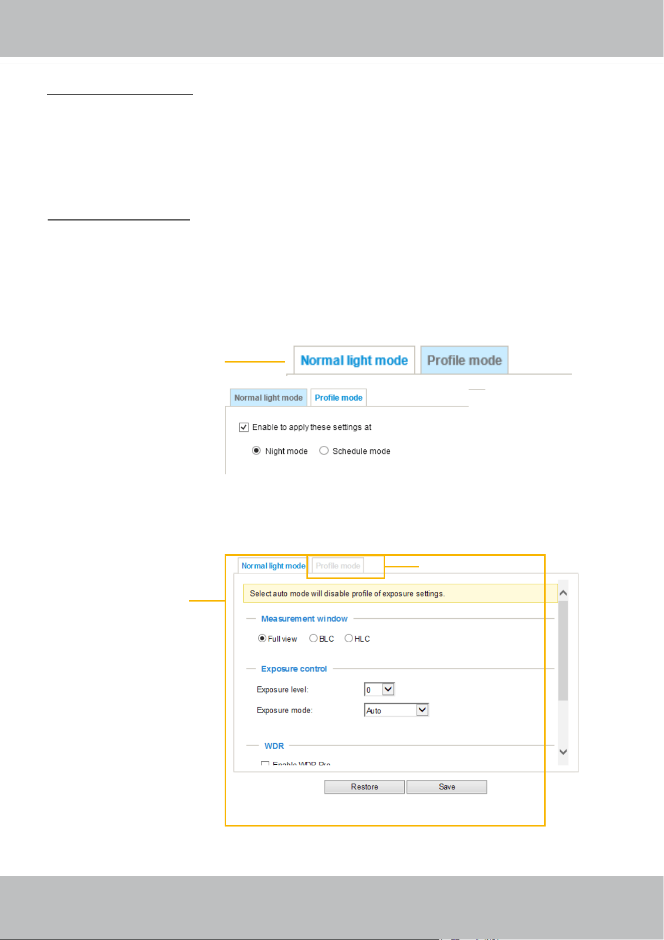
completed with the settings on this page, click Save to enable the setting. You can also click on Prole
mode to adjust all settings above in a pop-up window for special lighting conditions during a specic
period of time in a day.
Sensor Setting 2:
For special situations
Enable 3D Noise reduction
■ Check to enable noise reduction in order to reduce noises and ickers in image. This applies to the
onboard 3D Noise Reduction feature. Use the pull-down menu to adjust the reduction strength. Note
that applying this function to the video channel will consume system computing power.
3D Noise Reduction is mostly applied in low-light conditions. When enabled in a low-light condition
with fast moving objects, trails of after-images may occur. You may then select a lower strength level
or disable the function.
Electronic image stabilizer
Select the checkbox to enable the Electronic image stabilization (EIS) function.
Sensor Setting 2:
For customized situations such as
night mode.

VIVOTEK
User's Manual - 65
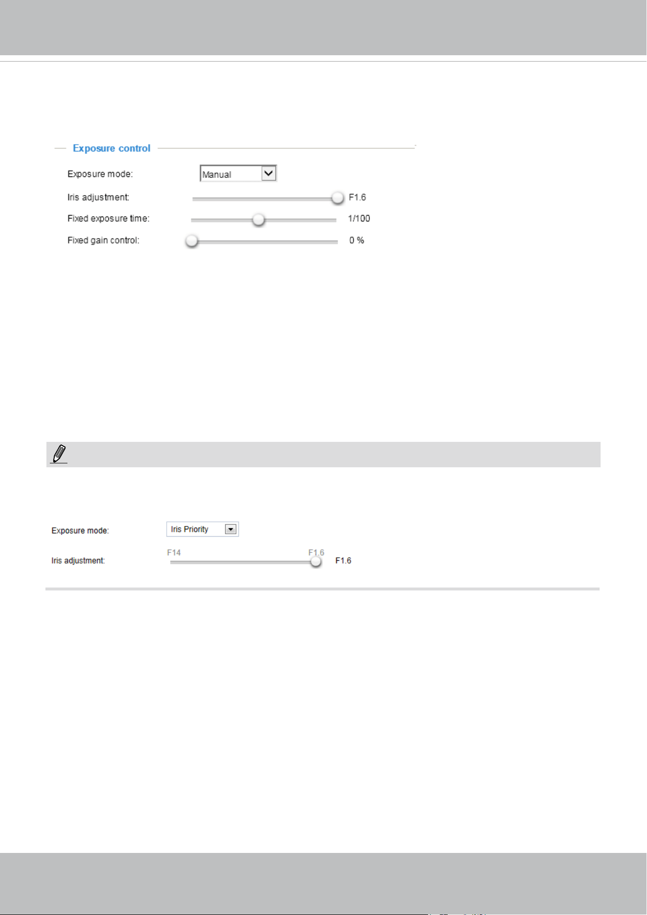
- Iris Priority: When selected, the Iris adjustment slide bar will appear, allowing you to select
an aperture size ranging from F14 to F1.6. Once a fixed value is selected, system firmware will
automatically tune the gain and exposure time to match an optimal exposure level.
The value is
measured in the F-number as the ratio of the focal length to the lens diameter. Iris size is inversely
proportional to the F-number; therefore, the smaller the F-number, the greater is the exposure ratio.
Smaller F-number (larger exposure ratio, largest size of lens aperture opening) is shown on the right of
the slide bar.
- Quality Priority: When selected, the embedded mapping table of aperture size and depth of eld will
apply when operating with the auto focus mechanism. This applies when both articial lights (city street
lights) and IR lights are present in scenes and the camera needs to select an appropriate aperture size
for an optimal focus. This is also coordinated with lens zoom ratio with different depths of view. For
example, when zooming in on a scene with a 20x or 30x zoom ratio, the FoV becomes very small, the
aperture size will adapt to enable the best possible focus to identify objects with the presence of both
articial lights and the camera's IR lights.
- Shutter Priority: When selected, the Exposure time slide bar will appear, allowing you to select an
exposure time ranging from 1/10,000, to 1/1 second. Once a xed value is selected, system rmware
will automatically tune the gain and iris settings to match an optimal exposure level.
Exposure control:
■
Exposure level: You can manually set the Exposure level, which ranges from -2.0 to +2.0 (dark
to bright). You can also select other values from the Exposure mode menus and select a preferred
scenario or manually congure the associated settings. You may prefer a shorter shutter time to better
capture moving objects, while a faster shutter reduces light and needs to be compensated by electrical
brightness gains.
■
Exposure mode:
Select Auto, Shutter Priority, Quality Priority, Iris Priority, or Manual mode according to your needs.
- Auto: System default, which automatically adjusts the iris, shutter speed, and gain for an optimmal
exposure level.
■ BLC (Back Light Compensation): This option will automatically add a “weighted region“ in the middle of
the window and give the necessary light compensation.
■
HLC: (Highlight Compensation). Firmware detects strong light sources and compensates on affected
spots to enhance the overall image quality. For example, the HLC helps reduce the glares produced by
spotlights or headlights.
Measurement Window: This function allows users to set measurement window(s) for low light
compensation. For example, where low-light objects are posed against an extremely bright background.
You may want to exclude the bright sunlight shining through a building's corridor.
■ Full view: Calculate the full range of view and offer appropriate
light compensation.
VIVOTEK
66 - User's Manual
■
WDR Pro (Wide Dynamic Range): Default is on. When set to Auto, you can select the strength of the
WDR function. The Low, Medium, High options correspond to the level of contrast between the overly-
lit area and the shaded areas. For example, the High option applies to a high contrast scenario. Note
that when the exposure time is set to longer than 1/60 second, the WDR function will be disabled.
■
Maximum gain control: Select a maximum value for the electronic gain from the slide bar. The gain
value also has its effect on the sensitivity of the IR cut lter. When applying the gain control, IR cut lter
setting will change accordingly.
• When Iris Priority is selected for the Exposure mode, the tunable aperture size is related to zoom
ratio. When using different zoom ratios, the range of aperture sizes can be different. When zoom ratio is
0x, the range of iris sizes is F1.6~F14. When zoom ratio is 20x, the iris size is F3.4.
NOTE:
Manual: Note that WDR and Defog functions will be disabled using the Manual mode setting.
- Manual: Select Manual to set a xed exposure time, iris, and gain. Then, tune the slide bar to set the
Exposure time, Iris adjustment, and Gain Control to the best image quality. A shorter exposure time
allows less amount of light to enter the sensor; while a higher gain control value generates certain
amount of noises.
Note the following when the Manual mode is selected:
1. The Exposure level bar will not be available.
2. The IR cut lter setting will switch to Day Mode. If it was previously congured into other modes,
the previous setting remains intact.
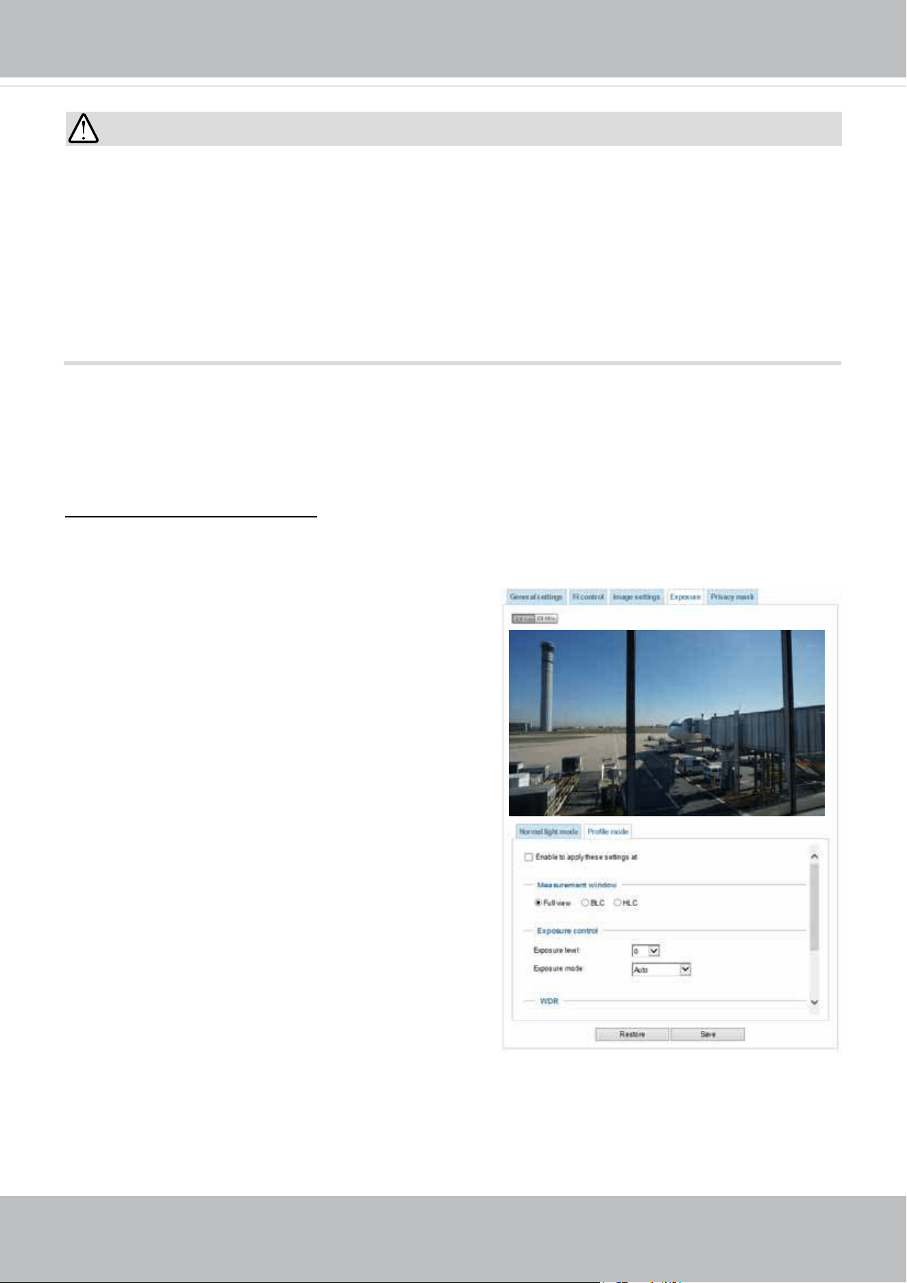
VIVOTEK
User's Manual - 67
IMPORTANT:
1. Because the exposure settings are also available in the Prole setting, incorrect congurations such
as a very high exposure level will let the camera consider it is operating in the Day mode even when
the ambient light is actually low. The camera will falsely remove the IR cut lter, and thus results in
distorted image colors.
Therefore, when the IR cut lter is in the Auto mode, the Prole setting is not available.
2. When set to the Night mode, the image display automatically changes to Black and White.
3. There is no Preview button in the Exposure window. Conguration changes are directly reected in the
live view window.
Please follow the steps below to set up a prole:
1. Select the Enable to apply these settings at
checkbox.
2. Select the applicable Night mode or Schedule mode.
Please manually enter a range of time if you choose
Schedule mode.
When a span of time is congured using the Schedule
mode, you can configure the Day/Night setting for
controlling the behavior of the IR cut lter during that
time.
3. Configure Exposure control settings in the folowing
columns. Please refer to previous dicussions for
detailed information.
4. Click Save to enable the setting and click Close to exit
the window.
Exposure Prole: (Only available when the IR cut lter is not set to the Auto mode)
If you want to congure another sensor and exposure setting for an individual day/night/schedule mode,
please click Prole mode to open the Prole of exposure settings page as shown below.
Enable to apply these settings at:
Select the mode this prole to apply to the Night mode or Schedule
mode. Please manually enter a range of time if you choose Schedule mode. Then check Save to take
effect.
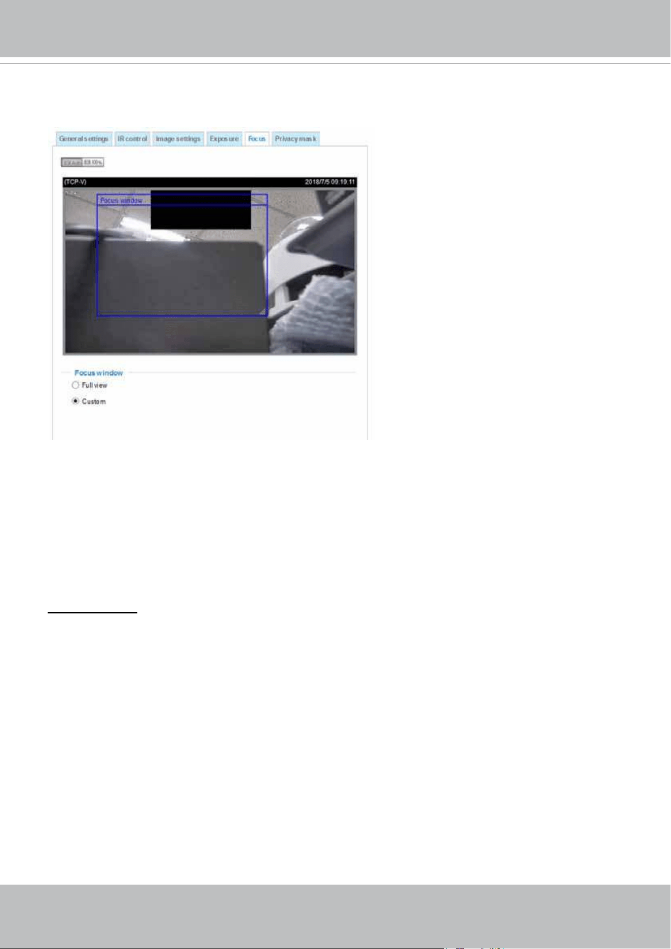
VIVOTEK
68 - User's Manual
Focus
Chances are while moving the lens around the surveillance area, focusing can be slow when
zooming in on a complex scene with no distinctive objects especially in the center of the eld
of view. If this occurs, you can select the Custom mode, and congure a Focus window in the
middle of the eld of view.
With a Focus window in the center or a place you prefer in the FOV, the camera can more
rapidly focus on an object of your interest while scanning through the entire surveillance area.
Focus window:
By default, the optimal focus is found on a full view window. You may designate a custom window within
your current eld of view to acquire the best focus out of it.
■
Full view: The focus tuning takes place by referring to the full view.
■
Custom: You can create a focus window and drag it to a place of interest in your view window. Note
that it is recommended to use this function only when you have a solid object in your view window that
is showing a consistent color or texture. This function will not take effect if you set the focus window on
a distant background.
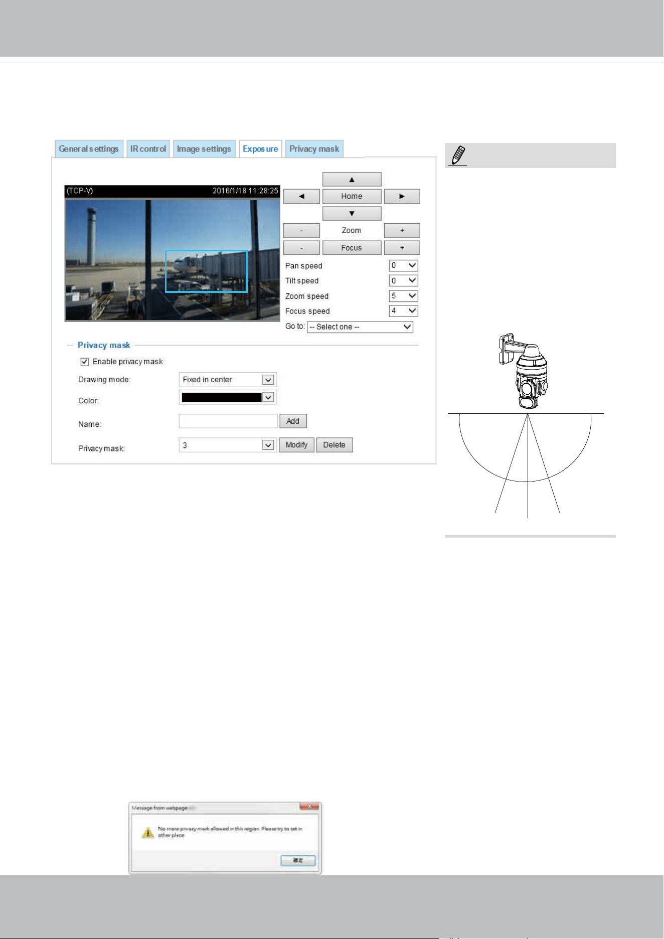
VIVOTEK
User's Manual - 69
Privacy mask
On this page, you can block out sensitive view areas to address privacy concerns.
■ To set the privacy mask windows, follow the steps below:
1. Click on the Enable privacy mask checkbox to enable this function.
2. Use mouse clicks on the screen to move to a place where you want to create a mask. You can also
use the PTZ panel to ne-tune the move to the target area.
3. Enter a name for the masking window. Click Add to create a new window.
4. Click on the Modify button and then use the mouse cursor to re-size the masking window, which is
recommended to be at least twice the size of the object (height and width) you want to cover. You can
select the Drawing mode as "Fixed in center" or "Drag to move."
• When using the Fixed in center mode, you can move to the area of your interest, and then
manually change the size and shape of the masking window.
• When using the Drag to move mode, you can move to an area of your interest using the PTZ
buttons above, and then click and drag to draw a masking window. The click to move maneuver
is not available when you select the Drag to move mode.
5. You can also change the color of the mask from the Color menu.
6. If preferred, move the eld of view to other places to create more privacy masks.
You may be prompted by the message when trying to create a privacy mask at angles between +70°
and -70°.
NOTE:
1. The navigation buttons here
also support the continuous
move. You can click and hold
down the button to move
across the screen until you
release the button.
2. You can not create privacy
masks at angles between
+70° and -70°.
90°
+70°
-70°
0°0°
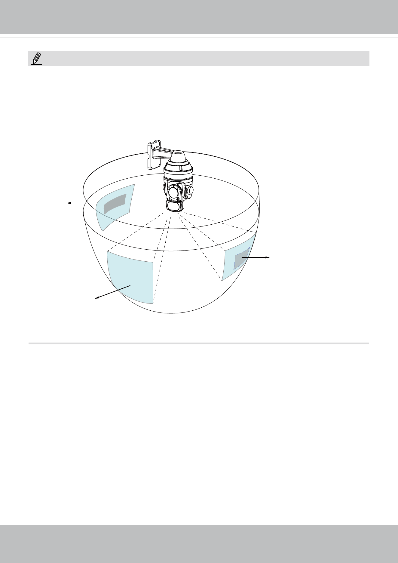
VIVOTEK
70 - User's Manual
NOTE:
• The camera supports "3D Privacy Mask." Privacy masks should stay at the same positions
regardless of how the camera lens may move.
• When the "Enable privacy mask" checkbox is deselected, no privacy masks will appear on screen.
• Up to 24 privacy mask windows can be congured over the camera's hemispheric coverage.
• If you want to delete a privacy mask window, select its name from the pull-down menu at the bottom,
and then click Delete to remove it.
Privacy mask
Current field of view
Privacy mask
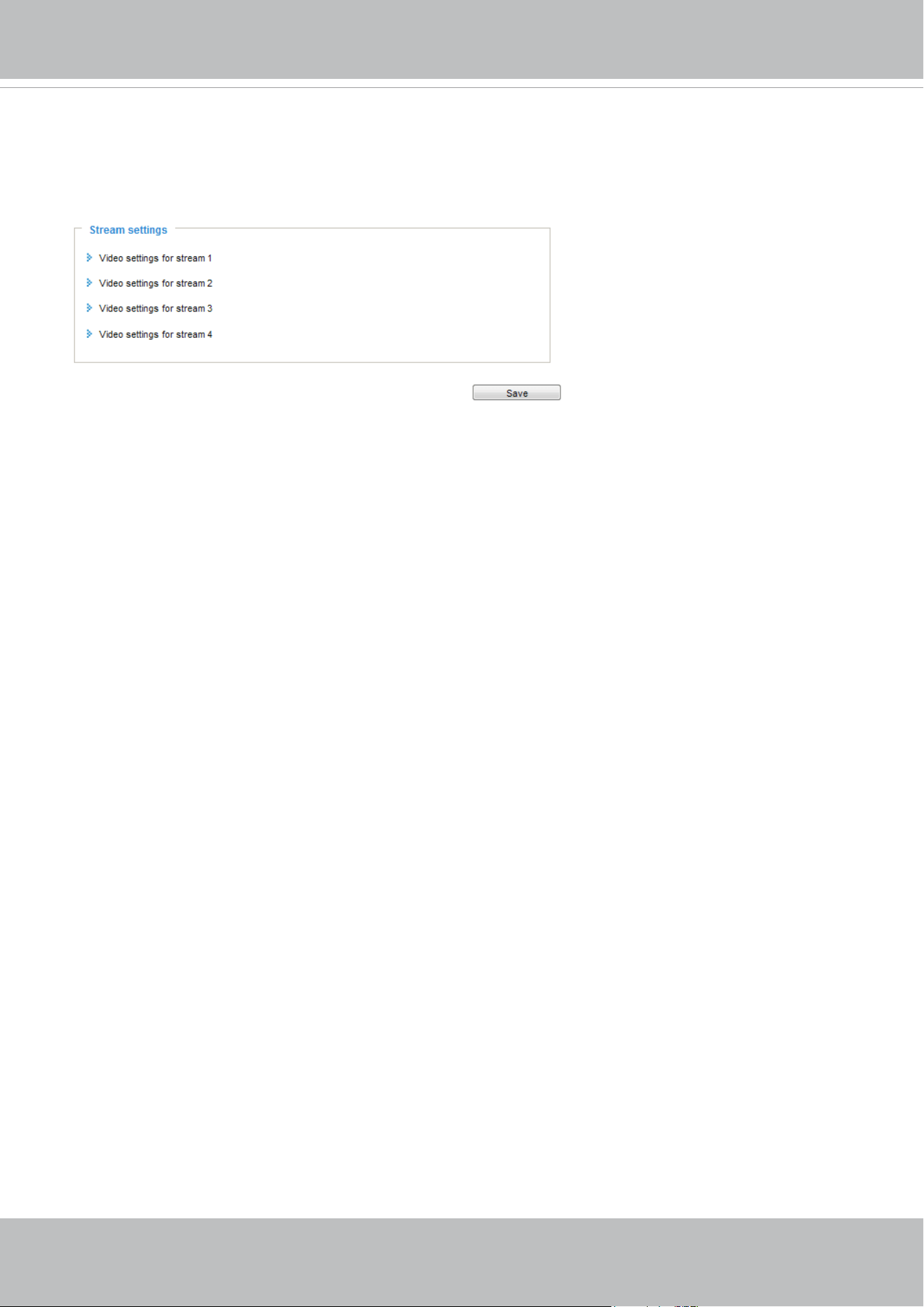
VIVOTEK
User's Manual - 71
Media > Video
Stream settings
This Network Camera supports multiple streams with frame sizes ranging from 384 x 216 to 1920 x 1080
pixels.
The denition of multiple streams:
■ Stream 1: Users can dene the Frame sizes, compression format, image quality, etc.
■ Stream 2: The default frame size for stream 2 is congured to 1280 x 720.
■ Stream 3: The default frame size for Stream 3 is set to the minimized 640 x 360 for viewing on mobile
devices.
■ Stream 4: The default frame size for stream 4 is congured to 1920 x 1080 in the H.265 or H.264
mode.
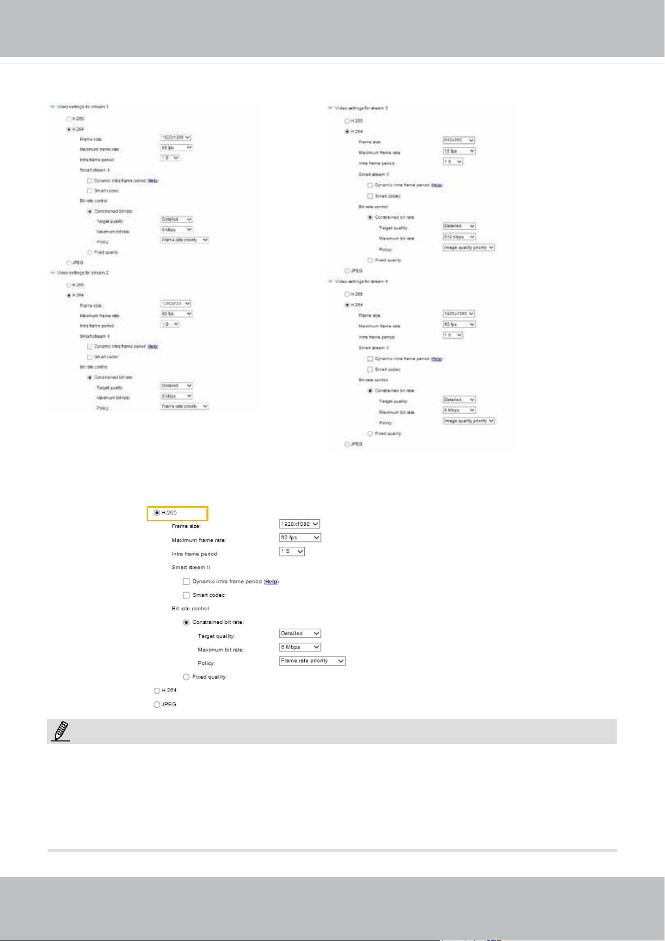
VIVOTEK
72 - User's Manual
Click the stream item to display the detailed information. .
This Network Camera offers real-time H.265, H.264, and MJPEG compression standards (Multiple
Codec) for real-time viewing. If the
H.265 / H.264 mode is selected, the video is streamed via RTSP
protocol. There are several parameters through which you can adjust the video performance:
►
Video quality and fixed quality refers to the compression rate, so a lower value will produce higher
quality.
►
Converting high-quality video may significantly increase the CPU loading, and you may encounter
streaming disconnection or video loss while capturing a complicated scene. In the event of occurance,
we suggest you customize a lower video resolution or reduce the frame rate to obtain smooth video.
NOTE:
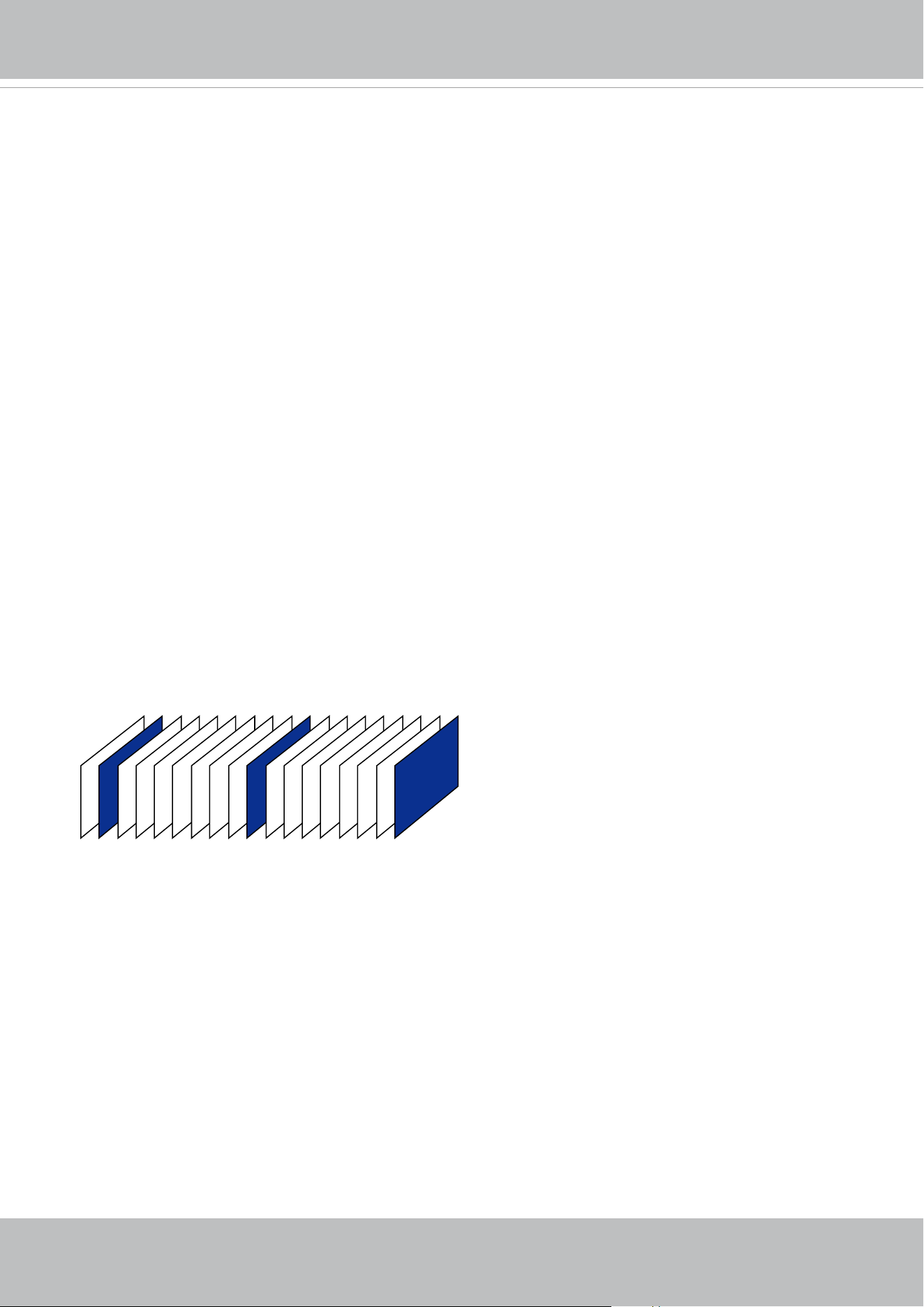
VIVOTEK
User's Manual - 73
■ Frame size
You can set up different video resolution for different viewing devices. For example, set a smaller
frame size and lower bit rate for remote viewing on mobile phones and a larger video size and a higher
bit rate for live viewing on web browsers. Note that a larger frame size takes up more bandwidth.
■ Maximum frame rate
This limits the maximum refresh frame rate per second. Set the frame rate higher for smoother video
quality and for recognizing moving objects in the eld of view.
If the power line frequency is set to 50Hz, the frame rates are selectable at 1fps, 2fps, 3fps, 5fps, 8fps,
10fps, 15fps, 20fps, 25fps, 30fps, 40fps, 45fps, and 50fps. If the power line frequency is set to 60Hz,
the frame rates are selectable at 1fps, 2fps, 3fps, 5fps, 8fps, 10fps, 15fps, 20fps, 25fps, 30fps, 40fps,
45fps, 50fps, 55fps, and 60fps. You can also select Customize and manually enter a value.
■ Intra frame period
Determine how often for rmware to plant an I frame. The shorter the duration, the more likely you
will get better video quality, but at the cost of higher network bandwidth consumption. Select the intra
frame period from the following durations: 1/4 second, 1/2 second, 1 second, 2 seconds, 3 seconds,
and 4 seconds.
►Dynamic Intra frame period
High quality motion codecs, such as H.265, utilize the redundancies between video frames to deliver
video streams at a balance of quality and bit rate.
The encoding parameters are summarized and illustrated below. The I-frames are completely self-
referential and they are largest in size. The P-frames are predicted frames. The encoder refers to the
previous I- or P-frames for redundant image information.
P I P P P P P P P I P P P P P P P I
By dynamically prolonging the intervals for I-frames insertion to up to 10 seconds, the bit rates required
for streaming a video can be tremendously reduced. When streaming a video of a static scene,
the Dynamic Intra frame feature can save up to 53% of bandwidth. The amount of bandwidth thus
saved is also determined by the activities in the eld of view. If activities occur in the scene, rmware
automatically shortens the I-frame insertion intervals in order to maintain image quality. In the low
light or night conditions, the sizes of P-frames tend to be enlarged due to the noises, and hence the
bandwidth saving effect is also reduced.
Streaming a typical 2MP scene normally requires 3~4Mb/s of bandwidth. With the Dynamic Intra frame
function, the bandwidth for streaming a medium-trafc scene can be reduced to 2~3Mb/s, and during
the no-trafc period of time, down to 500kb/s.
H.264/265 Frame Types
■
Smart stream II
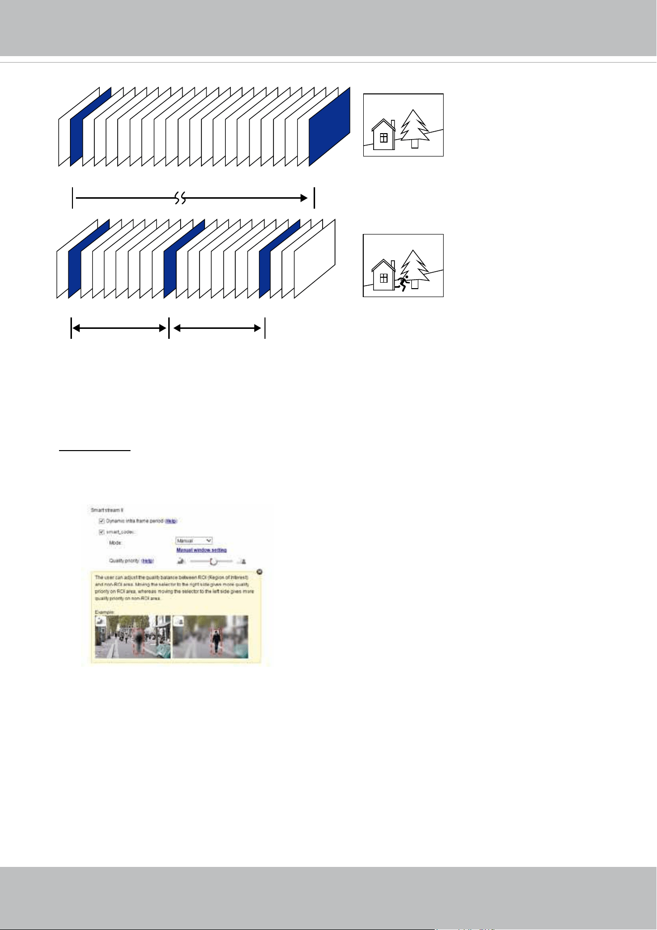
VIVOTEK
74 - User's Manual
P I P P P P P P P P P P P P P P P P P P P I
P I P P P P P P P I P P P P P P P I
Static scene
Activities
P P P
Dynamic Intra Frame w/
static scenes
Dynamic Intra Frame w/
activities in scenes
With the H.265 codec in an optimal scenario and when the Dynamic Intra frame and the Smart Stream
function are applied, an 80% of bandwidth saving can be achieved compared with using H.264 without
enabling these bandwidth-saving features.
►Smart codec: Smart codec effectively reduces the quality of the whole or the non-interested areas on a
screen and therefore reduces the bandwidth consumed.
You can manually specify the video quality for the foreground and the background areas.
Select an operation mode if Smart codec is preferred.
- Auto tracking: The Auto mode congures the whole screen into the non-interested area. The
video quality of part of the screen returns to normal when one or more objects move
in that area. The remainder of the screen where there are no moving objects (no pixel
changes) will still be transmitted in low-quality format.
- Manual: The Manual mode allows you to configure 3 ROI windows (Region of Interest, with
Foreground quality) on the screen. Areas not included in any ROI windows will be
considered as the non-interested areas. The details in the ROI areas will be transmitted in
a higher-quality video format.
As illustrated below, the upper screen may contain little details of your interest, while the
sidewalk on the lower screen is included in an ROI window.
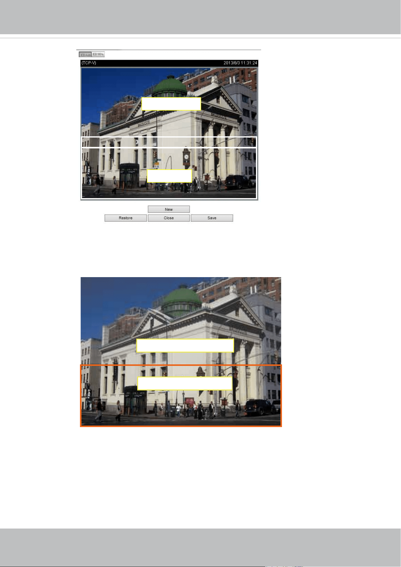
VIVOTEK
User's Manual - 75
X
ROI_0
X
ROI_0
ROI
non-interested
ROI: higher-quality
non-ROI: lower-quality
As the result, the lower screen is constantly displayed in high details, while the upper half
is transmitted using a lower-quality format. Although the upper half is transmitted using
a lower quality format, you still have an awareness of what is happening on the whole
screen.
- Hybrid: The major difference between the “Manual” mode and the “Hybrid” mode is that:
In the “Hybrid“ mode, any objects entering the non-interested area will restore the
video quality of the moving objects and the area around them. The video quality of the
associated non-interested area is immediately restored to normal to cover the moving
objects.
In the “Manual” mode, the non-interested area is always transmitted using a low-
quality format regardless of the activities inside.

VIVOTEK
76 - User's Manual
- Quality priority: Use the slide bar to tune the quality contrast between the ROI and non-
interested areas.
The farther the slide bar button is to the right, the higher the image quality of the ROI
areas. On the contrary, the farther the slide bar button to the left, the higher the image
quality of the non-interested area.
In this way, you may set up an ROI window as a privacy mask by covering a protected
area using an ROI window, while the remaining screen become the non-interested
area. You may then congure the non-interested area to have a high image quality, or
vice versa.
You should also select the Maximum bit rate from the pull-down menu as the threshold to
contain the bandwidth consumption for both the high- and low-quality video sections in a smart
stream.
■ B
it rate control
Constrained bit rate:
A complex scene generally produces a larger le size, meaning that higher bandwidth
will be needed for data transmission. The bandwidth utilization is configurable to
match a selected level, resulting in mutable video quality performance. The bit rates
are selectable at the following rates: 20Kbps, 30Kbps, 40Kbps, 50Kbps, 64Kbps,
128Kbps, 256Kbps, 512Kbps, 768Kbps, 1Mbps, 2Mbps, 3Mbps, 4Mbps, 6Mbps,
8Mbps, 10Mbps, 12Mbps, 14Mbps, ~ to 40Mbps. You can also select Customize
and manually enter a value up to 40Mbps.
• - Target quality: Select a desired quality ranging from Medium to Excellent
- Maximum bit rate: select a bit rate from the pull-down menu. The bit rate ranges
from 20kbps to a maximum of 40Mbps. The bit rate then becomes the Average or
Upper bound bit rate number. The Network Camera will strive to deliver video streams
around or within the bit rate limitation you impose.
- Policy: If Frame Rate Priority is selected, the Network Camera will try to maintain
the frame rate per second performance, while the image quality will be compromised.
If Image quality priority is selected, the Network Camera may drop some video
frames in order to maintain image quality.
Fixed quality:
On the other hand, if Fixed quality is selected, all frames are transmitted with the
same quality; bandwidth utilization is therefore unpredictable. The video quality
can be adjusted to the following settings: Medium, Standard, Good, Detailed, and
Excellent. You can also select Customize and manually enter a value.
Maximum bit rate: With the guaranteed image quality, you might still want to place
a bit rate limitation to control the size of video streams for bandwidth and storage
concerns. The congurable bit rate starts from 1Mbps to 40Mbps.
The Maximum bit rate setting in the Fixed quality configuration can ensure a
reasonable and limited use of network bandwidth. For example, in low light conditions
where a Fixed quality setting is applied, video packet sizes can tremendously
increase when noises are produced with electrical gains.
You may also manually enter a bit rate number by selecting the Customized option.
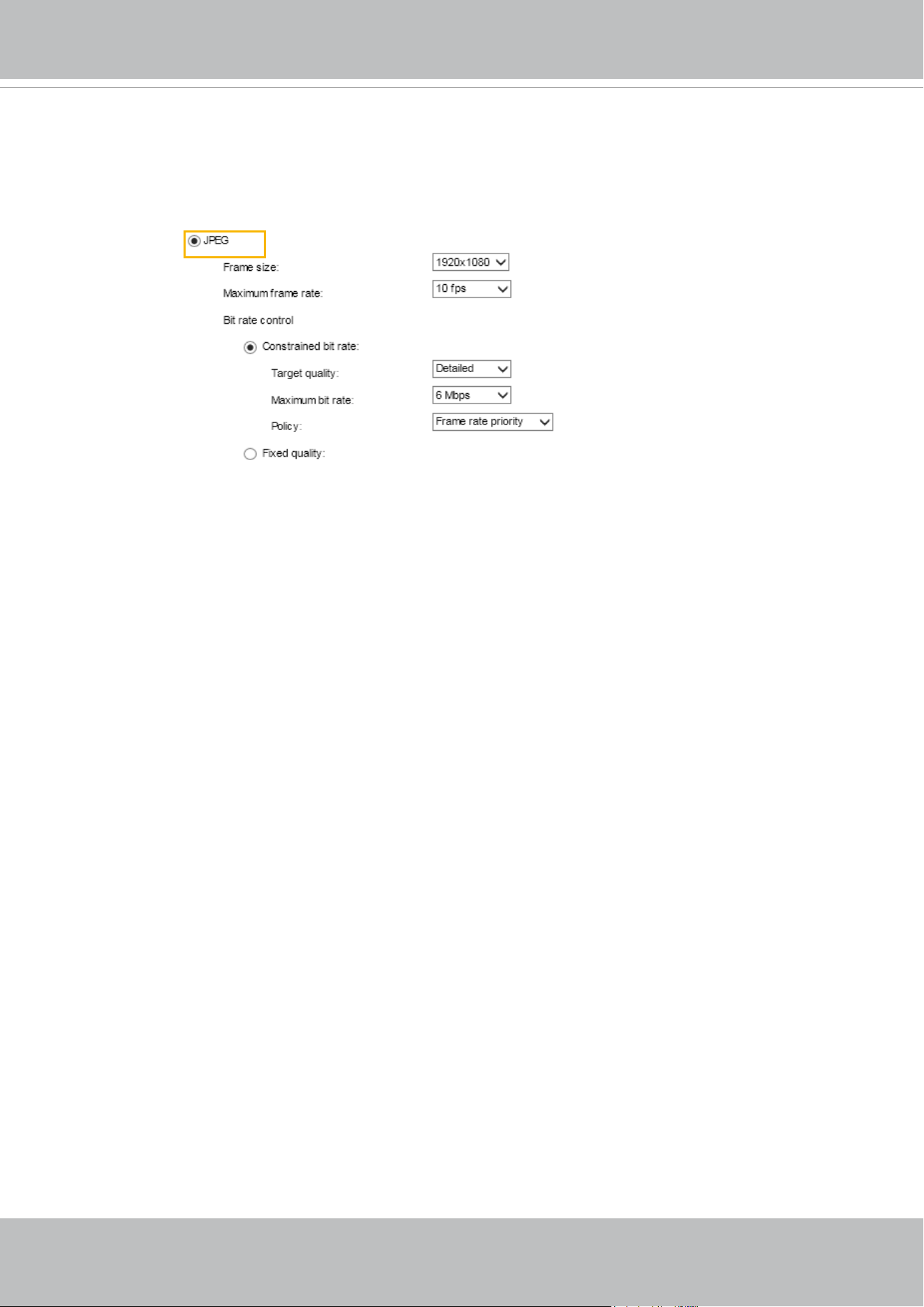
VIVOTEK
User's Manual - 77
If the JPEG mode is selected, the Network Camera sends consecutive JPEG images to the client,
producing a moving effect similar to a lmstrip. Every single JPEG image transmitted guarantees the
same image quality, which in turn comes at the expense of variable bandwidth usage. Because the
media contents are a combination of JPEG images, no audio data is transmitted to the client. There are
three parameters provided in MJPEG mode to control the video performance:
■ Frame size
You can set up different video resolution for different viewing devices. For example, set a smaller
frame size and lower bit rate for remote viewing on mobile phones and a larger video size and a higher
bit rate for live viewing on web browsers. Note that a larger frame size takes up more bandwidth.
■ Maximum frame rate
This limits the maximum refresh frame rate per second. Set the frame rate higher for smoother video
quality.
If the power line frequency is set to 50Hz, the frame rates are selectable from 1fps to 25fps. If the
power line frequency is set to 60Hz, the frame rates are selectable from 1fps to 30fps. You can also
select Customize and manually enter a value. The frame rate will decrease if you select a higher
resolution.
■ Video quality
Refer to the previous page setting an average or upper bound threshold for controlling the bandwidth
consumed for transmitting motion jpegs. The conguration method is identical to that for H.264.
For Constant Bit Rate and other settings, refer to the previous page for details.
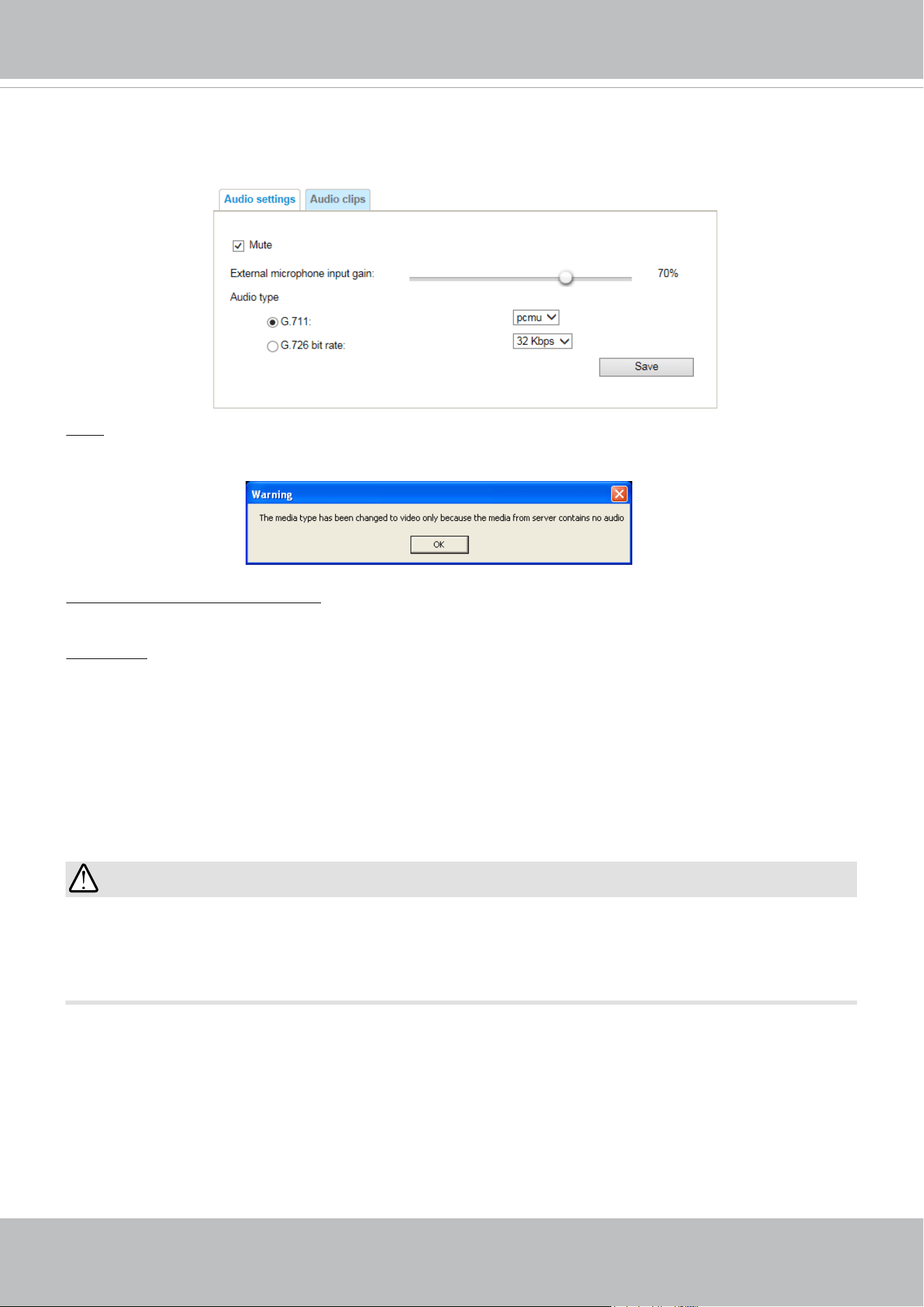
VIVOTEK
78 - User's Manual
Media > Audio
Audio Settings
Mute: Select this option to disable audio transmission from the Network Camera to all clients. Note that
if muted, no audio data will be transmitted even if audio transmission is enabled on the Client Settings
page. In that case, the following message is displayed:
External microphone input gain: Select the gain of the external audio input according to ambient
conditions. Adjust the gain from +21 db (most sensitive) or -33db (least sensitive).
Audio type: Select audio codec as G.711 or G.726, and the sampling bit rate .
■ G.711 also provides good sound quality and requires about 64Kbps. Select pcmu (μ-Law) or pcma
(A-Law) mode.
■ G.726 is a speech codec standard covering voice transmission at rates of 16, 24, 32, and 40kbit/s.
When completed with the settings on this page, click Save to enable the settings.
The network camera does not come with embedded microphone. An external microphone will be
necessary especially if you prefer the Audio Detection feature. By default, the Audio setting is muted,
and you need to manually deselect the Mute option.
IMPORTANT:
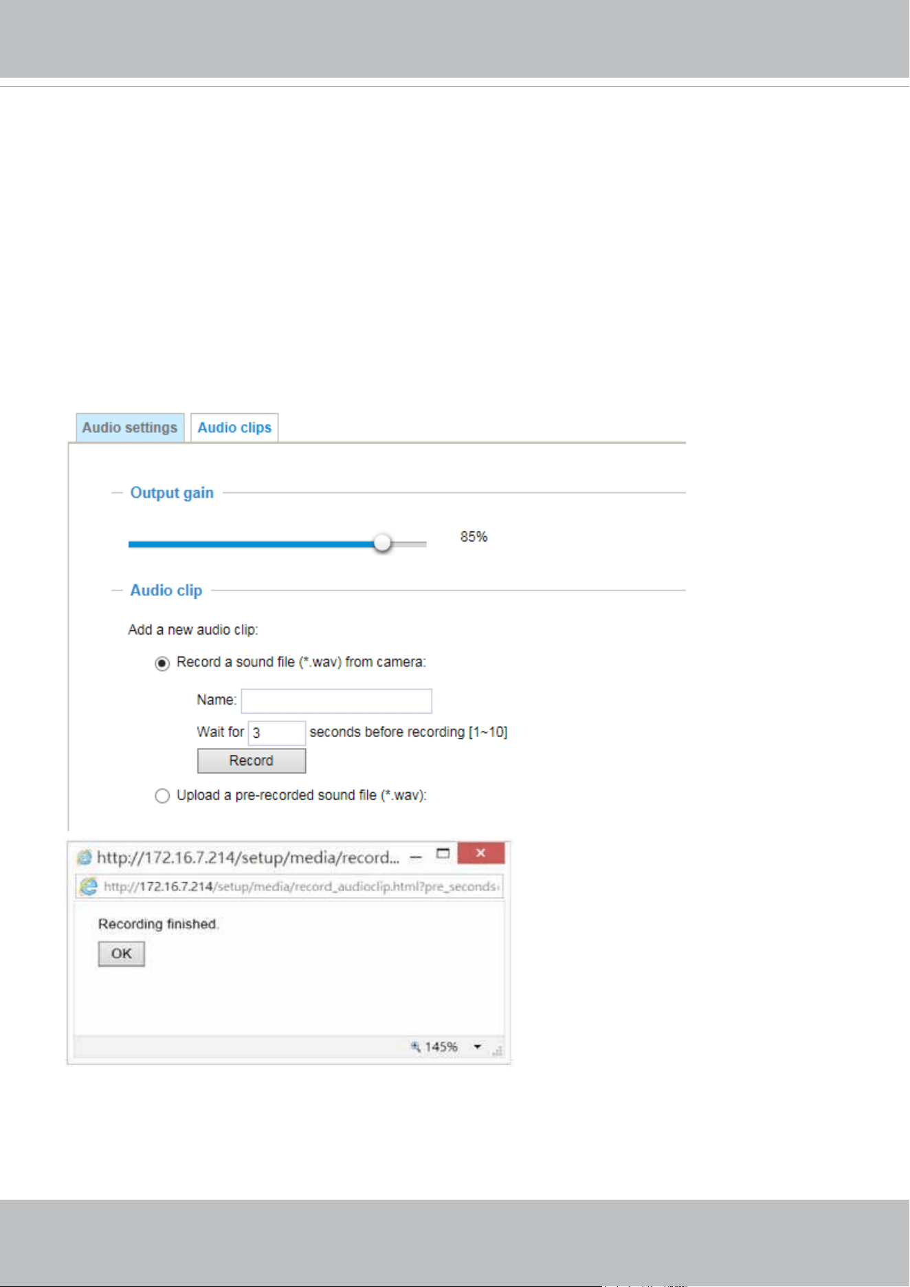
VIVOTEK
User's Manual - 79
Audio clips
■ Output gain: Use the slide bar to change the audio output gains value.
■ Audio clip: When the camera's audio input is connected to a microphone, you can record a short
period of audio recordings (1 to 10 seconds). You can also use the camera's embedded microphone to
record an audio clip, if available. Because the memory space is limited, a recording count down will be
available on screen.
You can also upload an audio file to the camera's flash memory. With amplified speakers, you can
playback the audio, e.g., to deter an intruder. A maximum of 2 audio clips in wav format are supported.
The maximum size of the audio le to be uploaded is 2,000Kbytes.
The voice alert is enabled in the Event settings > action > Play Audio Clip. The action c a n b e
associated with triggering conditions.
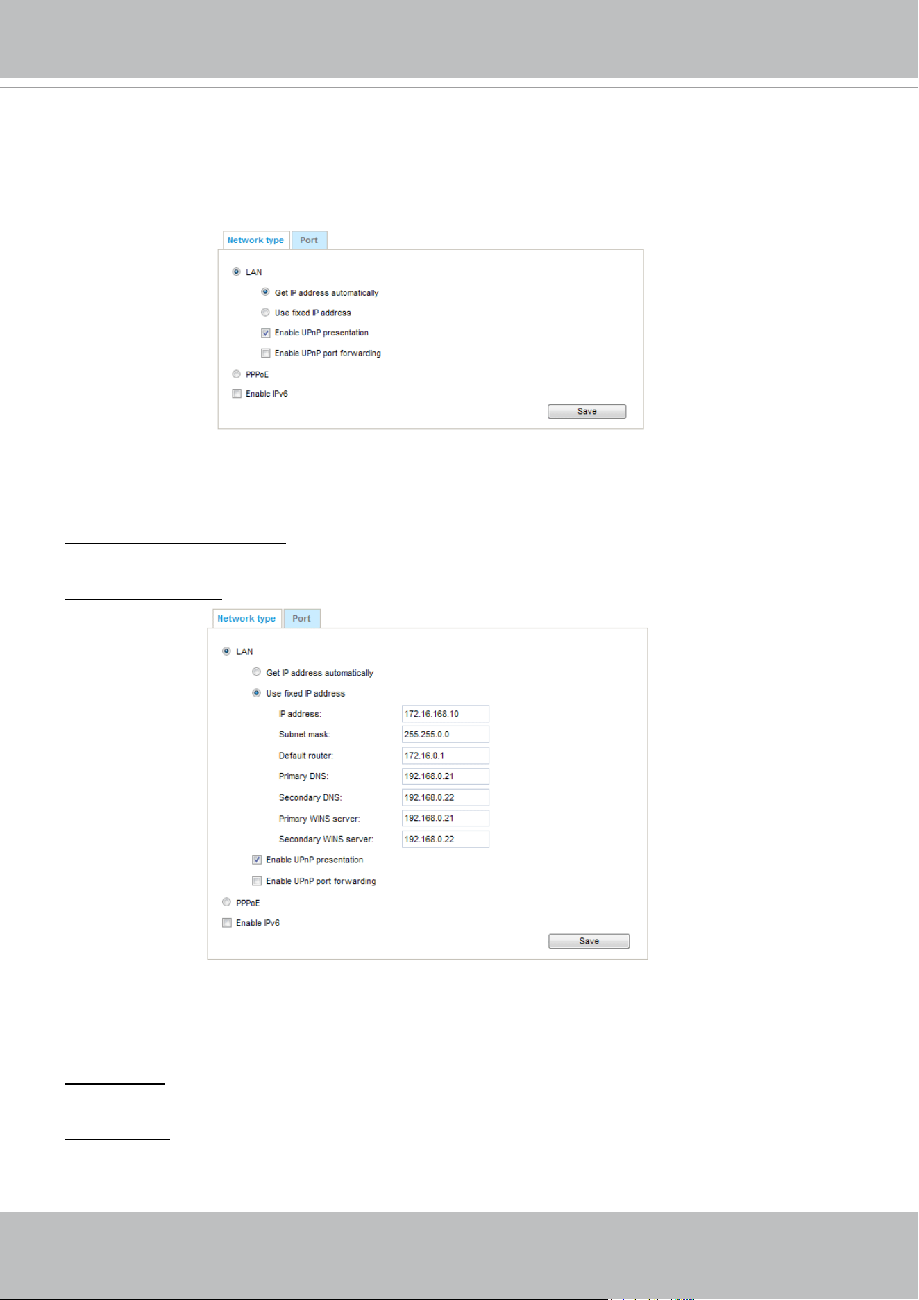
VIVOTEK
80 - User's Manual
Network > General settings
This section explains how to congure a wired network connection for the Network Camera.
Network Type
LAN
Select this option when the Network Camera is deployed on a local area network (LAN) and is intended
to be accessed by local computers. The default setting for the Network Type is LAN. Please rememer to
click on the Save button when you complete the Network setting.
Get IP address automatically: Select this option to obtain an available dynamic IP address assigned by
the DHCP server each time the camera is connected to the LAN.
Use xed IP address: Select this option to manually assign a static IP address to the Network Camera.
1. You can make use of VIVOTEK Installation Wizard 2 on the software CD to easily set up the Network
Camera on LAN. Please refer to Software Installation on page 26 for details.
2. Enter the Static IP, Subnet mask, Default router, and Primary DNS provided by your ISP or network
administrator.
Subnet mask: This is used to determine if the destination is in the same subnet. The default value is
“255.255.255.0”.
Default router: This is the gateway used to forward frames to destinations in a different subnet. Invalid
router setting will disable the transmission to destinations across different subnets.
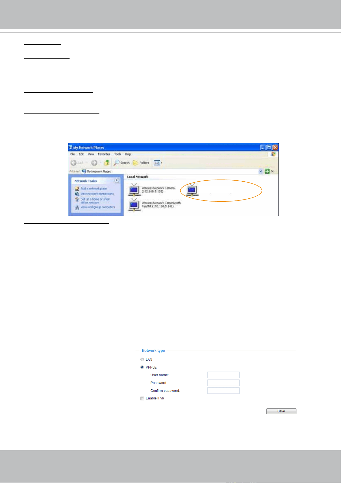
VIVOTEK
User's Manual - 81
Primary DNS: The primary domain name server that translates host names into IP addresses.
Secondary DNS: Secondary domain name server that backs up the Primary DNS.
Primary WINS server: The primary WINS server that maintains the database of computer names and IP
addresses.
Secondary WINS server: The secondary WINS server that maintains the database of computer names
and IP addresses.
Enable UPnP presentation: Select this option to enable UPnP
TM
presentation for your Network Camera
so that whenever a Network Camera is presented to the LAN, the shortcuts to connected Network
Cameras will be listed in My Network Places. You can click the shortcut to link to the web browser.
Currently, UPnP
TM
is supported by Windows XP or later. Note that to utilize this feature, please make
sure the UPnP
TM
component is installed on your computer.
Enable UPnP port forwarding: To access the Network Camera from the Internet, select this option to
allow the Network Camera to open ports automatically on the router so that video streams can be sent
out from a LAN. To utilize of this feature, make sure that your router supports UPnP
TM
and it is activated.
PPPoE (Point-to-point over Ethernet)
Select this option to congure your Network Camera to make it accessible from anywhere as long as
there is an Internet connection. Note that to utilize this feature, it requires an account provided by your
ISP.
Follow the steps below to acquire your Network Camera’s public IP address.
1. Set up the Network Camera on the LAN.
2. Go to Conguration > Event > Event settings > Add server (please refer to Add server on page 132) to
add a new email or FTP server.
3. Go to Conguration > Event > Event settings > Add media (please refer to Add media on page 123).
Select System log so that you will receive the system log in TXT le format which contains the
Network Camera’s public IP address in your email or on the FTP server.
4. Go to Conguration > Network > General settings > Network type. Select PPPoE and enter the user
name and password provided by your ISP. Click Save to enable the setting.
5. The Network Camera will reboot.
6. Disconnect the power to the Network Camera; remove it from the LAN environment.
Mega-pixel Network Camera (192.168.5.151)
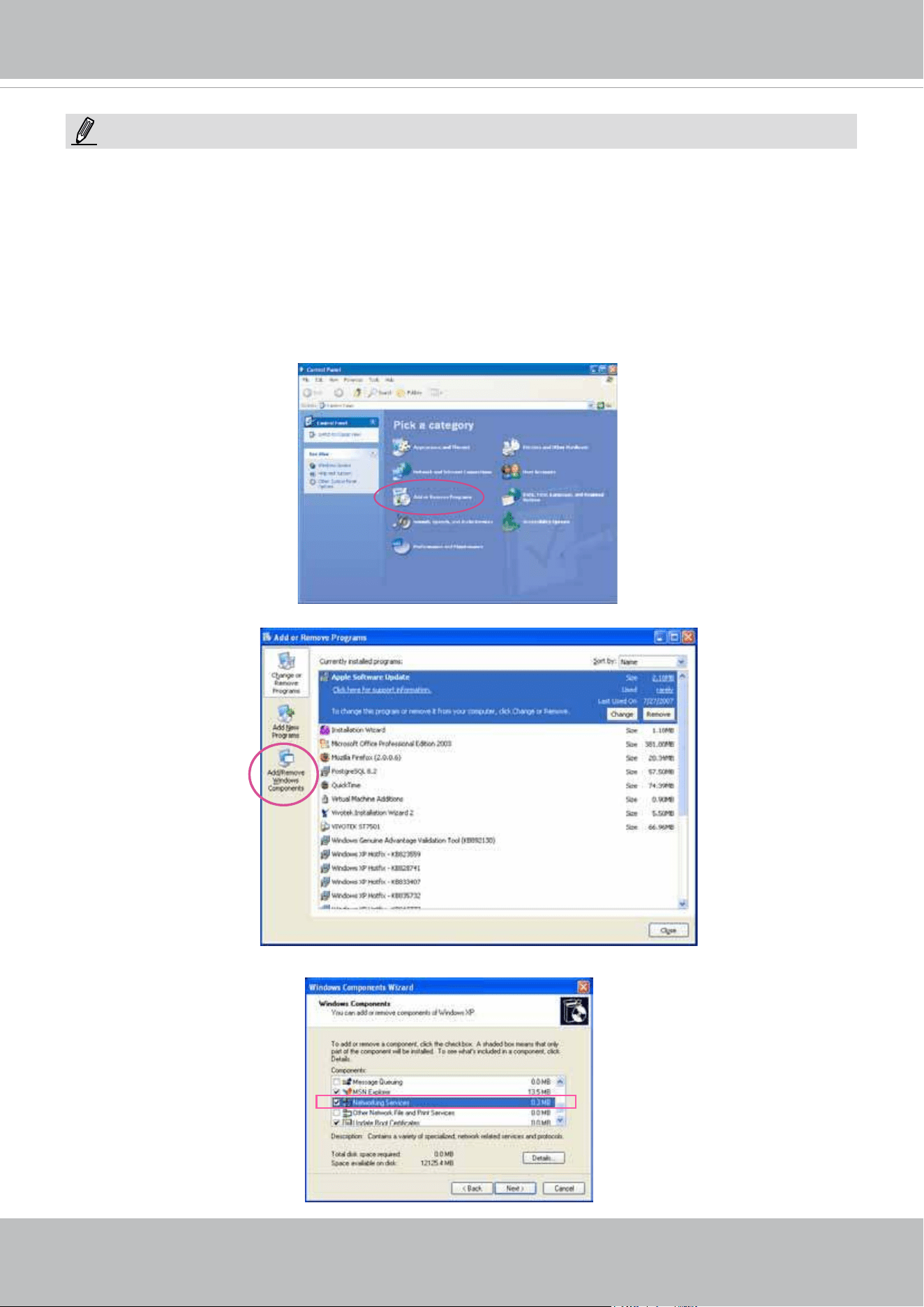
VIVOTEK
82 - User's Manual
► If the default ports are already used by other devices connected to the same router, the Network
Camera will select other ports for the Network Camera.
► If UPnP
TM
is not supported by your router, you will see the following message:
Error: Router does not support UPnP port forwarding.
► Steps to enable the UPnP
TM
user interface on your computer:
Note that you must log on to the computer as a system administrator to install the UPnP
TM
components.
1. Go to Start, click Control Panel, then click Add or Remove Programs.
2. In the Add or Remove Programs dialog box, click Add/Remove Windows Components.
3.
In the Windows Components Wizard dialog box, select Networking Services and click Details.
NOTE:
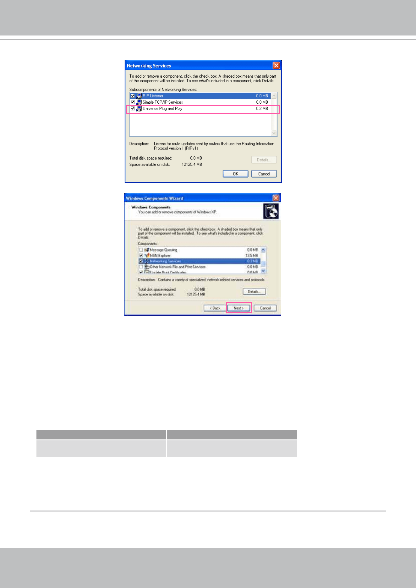
VIVOTEK
User's Manual - 83
4. In the Networking Services dialog box, select Universal Plug and Play and click OK.
5. Click Next in the following window.
6. Click Finish. UPnP
TM
is enabled.
► How does UPnP
TM
work?
UPnP
TM
networking technology provides automatic IP conguration and dynamic discovery of devices
added to a network. Services and capabilities offered by networked devices, such as printing and le
sharing, are available among each other without the need for cumbersome network conguration. In
the case of Network Cameras, you will see Network Camera shortcuts under My Network Places.
► Enabling UPnP port forwarding allows the Network Camera to open a secondary HTTP port on the
router-not HTTP port-meaning that you have to add the secondary HTTP port number to the Network
Camera’s public address in order to access the Network Camera from the Internet. For example,
when the HTTP port is set to 80 and the secondary HTTP port is set to 8080, refer to the list below for
the Network Camera’s IP address.
From the Internet In LAN
http://203.67.124.123:8080 http://192.168.4.160 or
http://192.168.4.160:8080
► If the PPPoE settings are incorrectly configured or the Internet access is not working, restore the
Network Camera to factory default; please refer to Restore on page 57 for details. After the Network
Camera is reset to factory default, it will be accessible on the LAN.
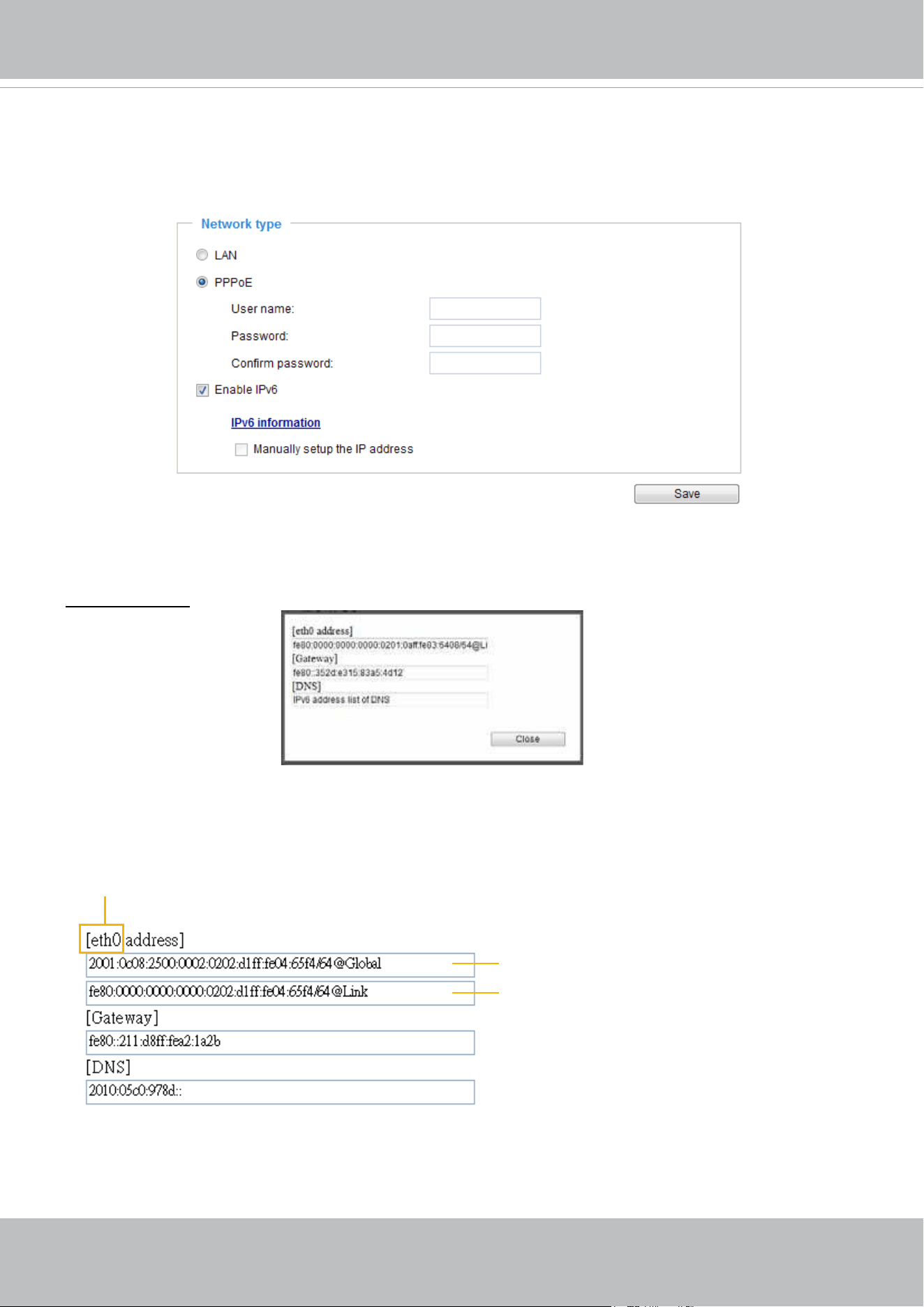
VIVOTEK
84 - User's Manual
Enable IPv6
Select this option and click Save to enable IPv6 settings.
Please note that this only works if your network environment and hardware equipment support IPv6. The
browser should be Microsoft
®
Internet Explorer 6.5, Mozilla Firefox 3.0 or above.
When IPv6 is enabled, by default, the network camera will listen to router advertisements and be
assigned with a link-local IPv6 address accordingly.
IPv6 Information: Click this button to obtain the IPv6 information as shown below.
If your IPv6 settings are successful, the IPv6 address list will be listed in the pop-up window. The IPv6
address will be displayed as follows:
Link-global IPv6 address/network mask
Link-local IPv6 address/network mask
Refers to Ethernet
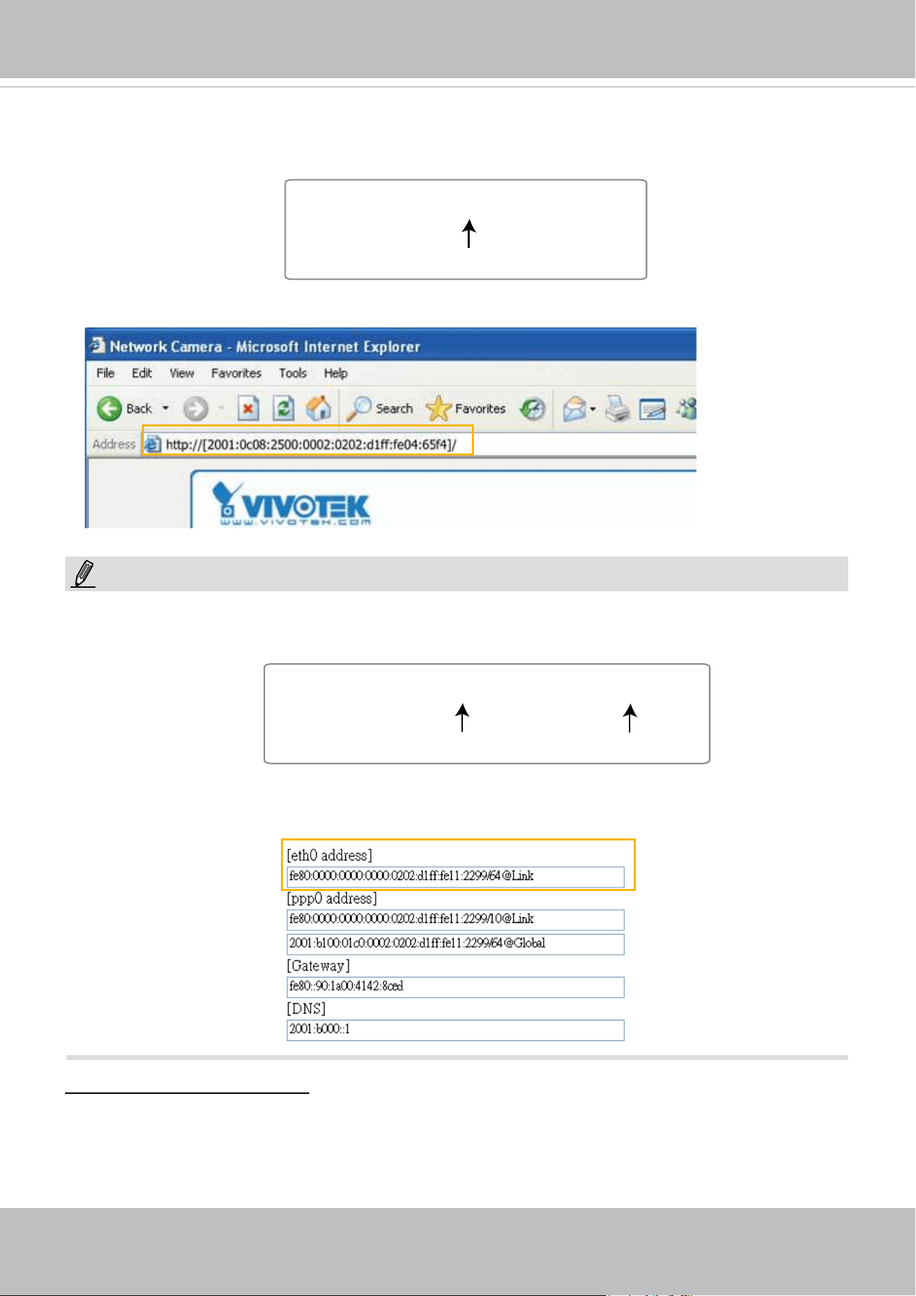
VIVOTEK
User's Manual - 85
Please follow the steps below to link to an IPv6 address:
1. Open your web browser.
2. Enter the link-global or link-local IPv6 address in the address bar of your web browser.
3. The format should be:
4. Press Enter on the keyboard or click Refresh button to refresh the webpage.
For example:
► If you have a Secondary HTTP port (the default value is 8080), you can also link to the webpage in
the following address format: (Please refer to HTTP streaming on page 87 for detailed information.)
► If you choose PPPoE as the Network Type, the [
PPP0 address] will be displayed in the IPv6
information column as shown below.
Manually setup the IP address: Select this option to manually set up IPv6 settings if your network
environment does not have a DHCPv6 server and router advertisements-enabled routers.
If you select this item, the following blanks will be displayed for you to enter the corresponding
information:
http://[2001:0c08:2500:0002:0202:d1ff:fe04:65f4]/
IPv6 address
http://[2001:0c08:2500:0002:0202:d1ff:fe04:65f4]/:8080
IPv6 address
Secondary HTTP port
NOTE:
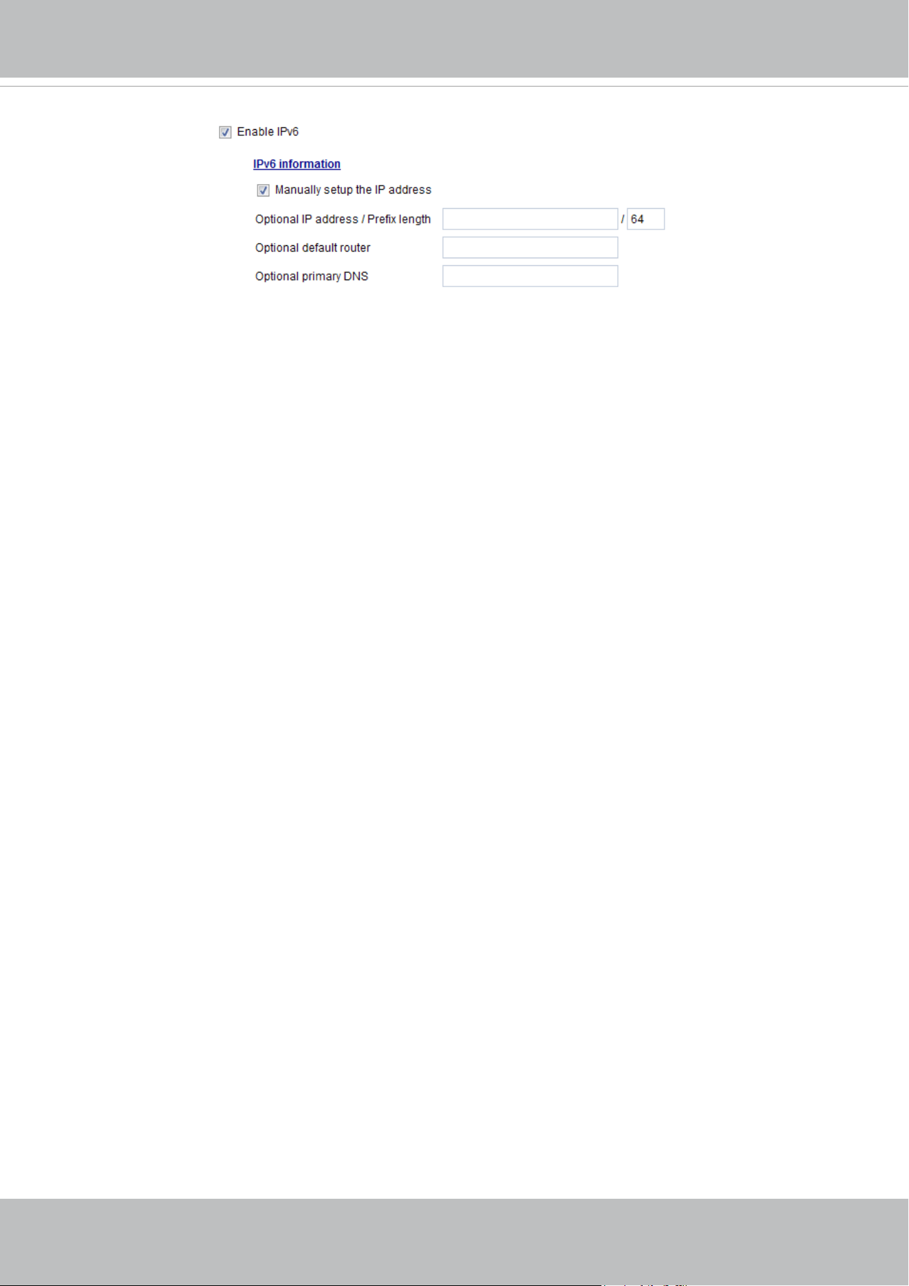
VIVOTEK
86 - User's Manual
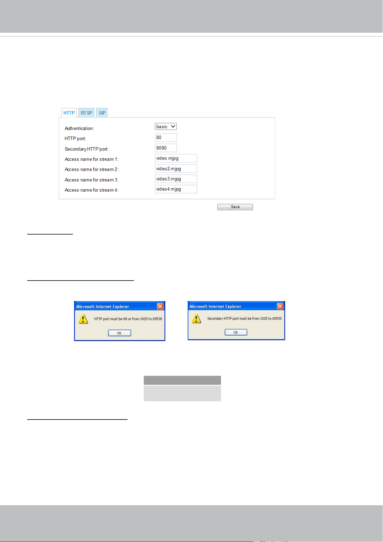
VIVOTEK
User's Manual - 87
Network > Streaming protocols
HTTP streaming
To utilize HTTP authentication, make sure that your have set a password for the Network Camera rst;
please refer to Security > User account on page 100 for details.
Authentication: Depending on your network security requirements, the Network Camera provides two
types of security settings for an HTTP transaction: basic and digest.
If
basic authentication is selected, the password is sent in plain text format and there can be potential
risks of being intercepted. If
digest authentication is selected, user credentials are encrypted using MD5
algorithm and thus provide better protection against unauthorized accesses.
HTTP port / Secondary HTTP port: By default, the HTTP port is set to 80 and the secondary HTTP port is
set to 8080. They can also be assigned to another port number between 1025 and 65535. If the ports are
incorrectly assigned, the following warning messages will be displayed:
To access the Network Camera on the LAN, both the HTTP port and secondary HTTP port can be used
to access the Network Camera. For example, when the HTTP port is set to 80 and the secondary HTTP
port is set to 8080, refer to the list below for the Network Camera’s IP address.
Access name for stream 1 ~ 5: This Network camera supports multiple streams simultaneously. The
access name is used to identify different video streams. Users can click Media > Video > Stream
settings to set up the video quality of linked streams. For more information about how to set up the video
quality, please refer to Stream settings on page 71.
When using Mozilla Firefox to access the Network Camera and the video mode is set to JPEG, users
will receive video comprised of continuous JPEG images. This technology, known as “server push”,
allows the Network Camera to feed live pictures to Mozilla Firefox.
On the LAN
http://192.168.4.160 or
http://192.168.4.160:8080
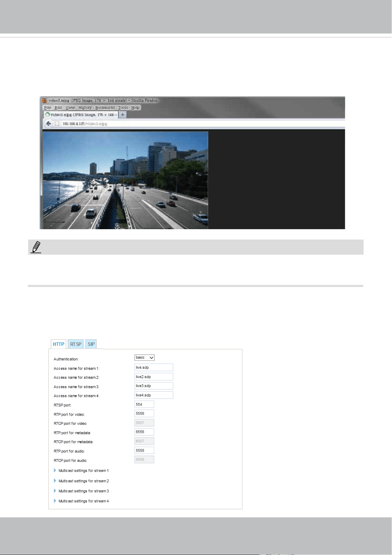
VIVOTEK
88 - User's Manual
URL command -- http://<ip address>:<http port>/<access name for stream 1, 2, 3, 4, or 5>
For example, when the Access name for stream 2 is set to video2.mjpg:
1. Launch the Mozilla Firefox browser.
2. Type the above URL command in the address bar. Press Enter.
3. The JPEG images will be displayed in your web browser.
► Microsoft
®
Internet Explorer does not support server push technology; therefore, using http://<ip
address>:<http port>/<access name for stream 1, 2, 3, 4, or 5>
will not work.
RTSP Streaming
To utilize RTSP streaming authentication, make sure that you have set a password for controlling the
access to video stream rst. Please refer to Security > User account on page 100 for details.
NOTE:
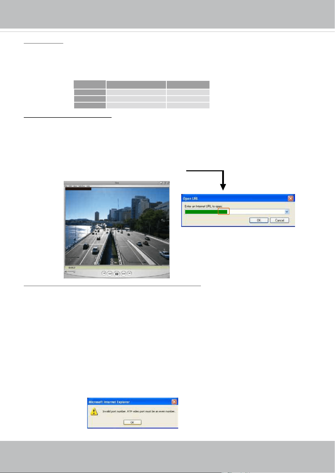
VIVOTEK
User's Manual - 89
Authentication: Depending on your network security requirements, the Network Camera provides three
types of security settings for streaming via RTSP protocol: disable, basic, and digest.
If basic authentication is selected, the password is sent in plain text format, but there can be potential
risks of it being intercepted. If
digest authentication is selected, user credentials are encrypted using
MD5 algorithm, thus providing better protection against unauthorized access.
The availability of the RTSP streaming for the three authentication modes is listed below:
Access name for stream 1 ~ 5: This Network camera supports multiple streams simultaneously. The
access name is used to differentiate the streaming source.
If you want to use an
RTSP player to access the Network Camera, you have to set the video mode to
H.265 / H.264 and use the following RTSP URL command to request transmission of the streaming data.
rtsp://<ip address>:<rtsp port>/<access name for stream 1 to 5>
For example, when the access name for stream 1 is set to live.sdp:
1. Launch an RTSP player.
2. Choose File > Open URL. A URL dialog box will pop up.
3. Type the above URL command in the text box.
4. The live video will be displayed in your player as shown below.
RTSP port /RTP port for video, audio/ RTCP port for video, audio
■ RTSP (Real-Time Streaming Protocol) controls the delivery of streaming media. By default, the port
number is set to 554.
■ The RTP (Real-time Transport Protocol) is used to deliver video and audio data to the clients. By
default, the RTP port for video is set to 5556 and the RTP port for audio is set to 5558.
■ The RTCP (Real-time Transport Control Protocol) allows the Network Camera to transmit the data by
monitoring the Internet trafc volume. By default, the RTCP port for video is set to 5557 and the RTCP
port for audio is set to 5559.
The ports can be changed to values between 1025 and 65535. The RTP port must be an even number
and the RTCP port is the RTP port number plus one, and thus is always an odd number. When the RTP
port changes, the RTCP port will change accordingly.
If the RTP ports are incorrectly assigned, the following warning message will be displayed:
rtsp://192.168.5.151:554/live.sdp
Quick Time player VLC
Disable O O
Basic O O
Digest O X
Video 16:38:01 2012/01/25
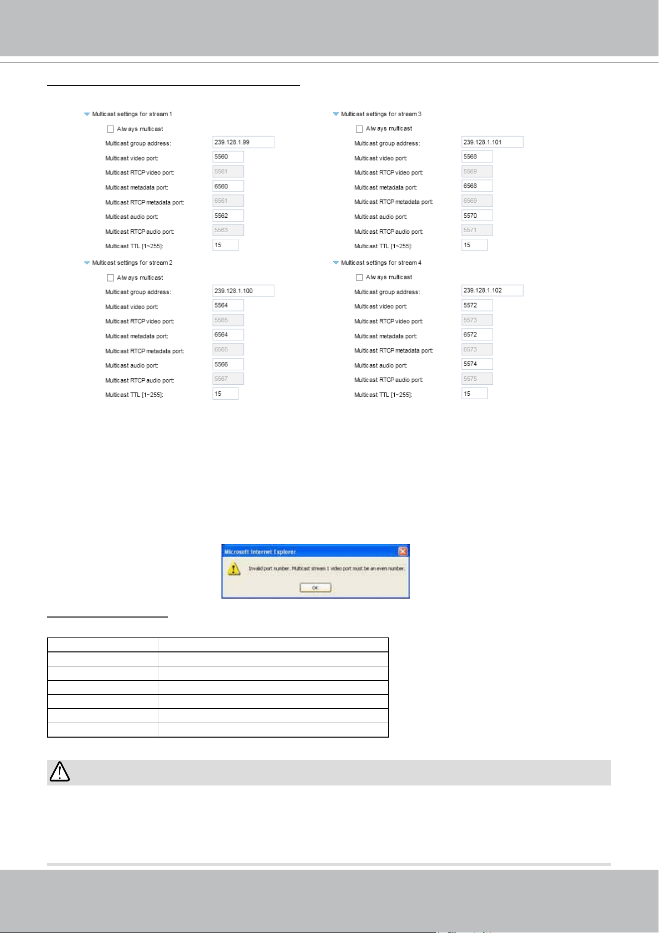
VIVOTEK
90 - User's Manual
Multicast settings for stream 1, 2, 3, and 4: Click the items to display the detailed configuration
information. Select the Always multicast option to enable multicast for video streams.
Unicast video transmission delivers a stream through point-to-point transmission; multicast, on the other
hand, sends a stream to the multicast group address and allows multiple clients to acquire the stream at
the same time by requesting a copy from the multicast group address. Therefore, enabling multicast can
effectively save Internet bandwith.
The ports can be changed to values between 1025 and 65535. The multicast RTP port must be an even
number and the multicast RTCP port number is the multicast RTP port number plus one, and thus is
always odd. When the multicast RTP port changes, the multicast RTCP port will change accordingly.
If the multicast RTP video ports are incorrectly assigned, the following warning message will be
displayed:
Multicast TTL [1~255]: The multicast TTL (Time To Live) is the value that tells the router the range a
packet can be forwarded.
Initial TTL Scope
0 Restricted to the same host
1 Restricted to the same subnetwork
32 Restricted to the same site
64 Restricted to the same region
128 Restricted to the same continent
255 Unrestricted in scope
IMPORTANT:
The Multicast metadata port is utilized by VIVOTEK VADP modules to transfer video analytics results,
PTZ stream, textual data, and event messages between the camera and the client side running and
observing the video analysis. If your client side computer is located outside the local network, you may
need to open the associated TCP port on routers and rewall.
VIVOTEK
User's Manual - 91
Two way audio port:
The Network Camera supports two way audio communication so that operators can transmit and receive
audio simultaneously. By using the Network Camera’s built-in or external microphone and an external
speaker, you can communicate with people around the Network Camera.
Note that as JPEG only transmits a series of JPEG images to the client, to enable the two-way audio
function, make sure the video mode is set to H.264 or H.265 on the Media > Video > Stream settings
page and the media option is set to “Media > Video > Stream settings” on the Client Settings page.
Please refer to Client Settings on page 44 and Stream settings on page 71.
SIP
SIP is short for Session Initiation Protocol. If necessary, you can change the default port number, 5060,
to one between 1025 and 65535.
Audio transmitted from operators
Audio transmitted to operators
America
Taiwan
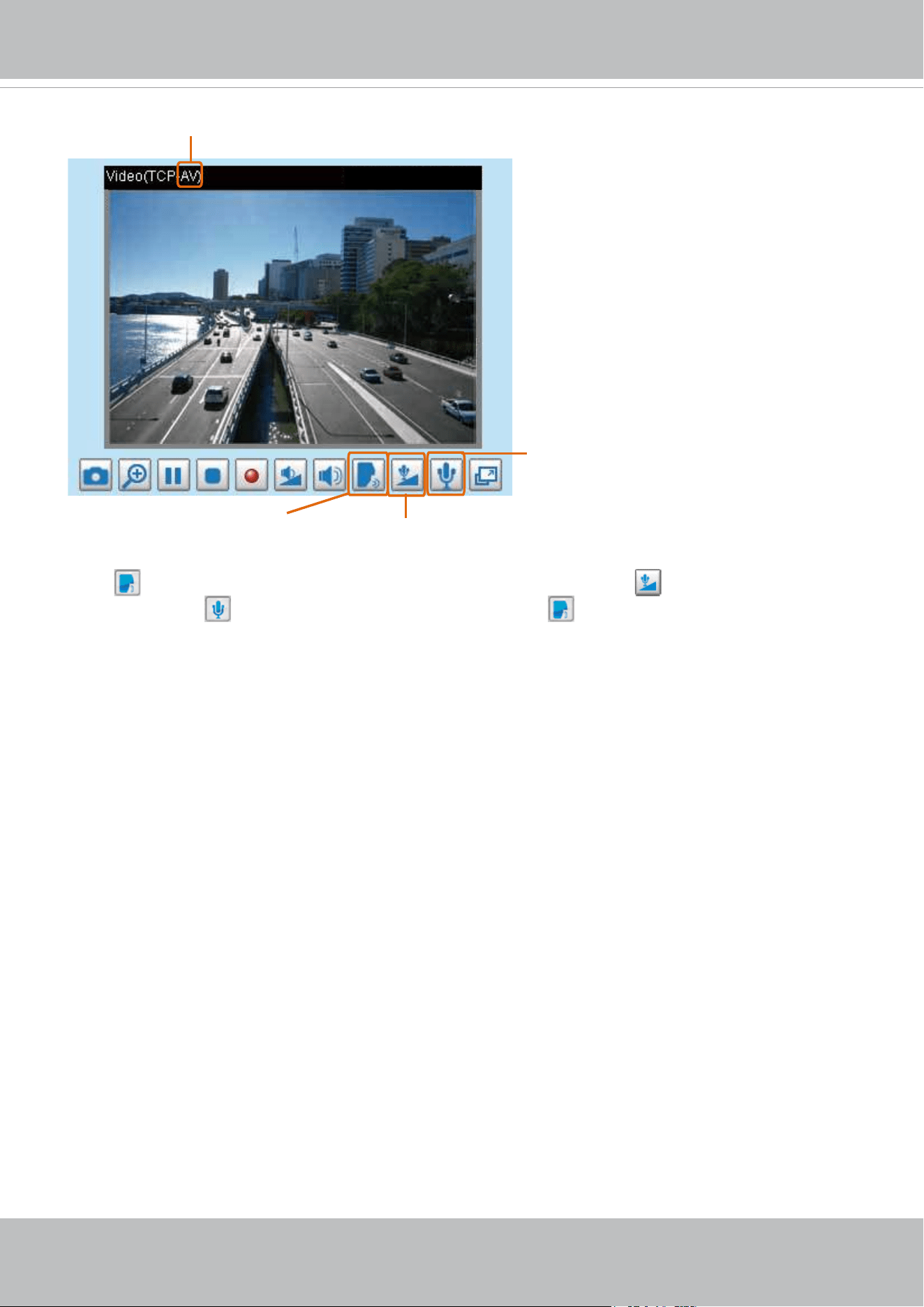
VIVOTEK
92 - User's Manual
Click to enable audio transmission to the Network Camera; click to adjust the volume of
microphone; click
to turn off the audio. To stop talking, click again.
2016/06/09 17:08:56
Audio is being transmitted to the Network Camera
Mute
Mic Volume
Talk Button
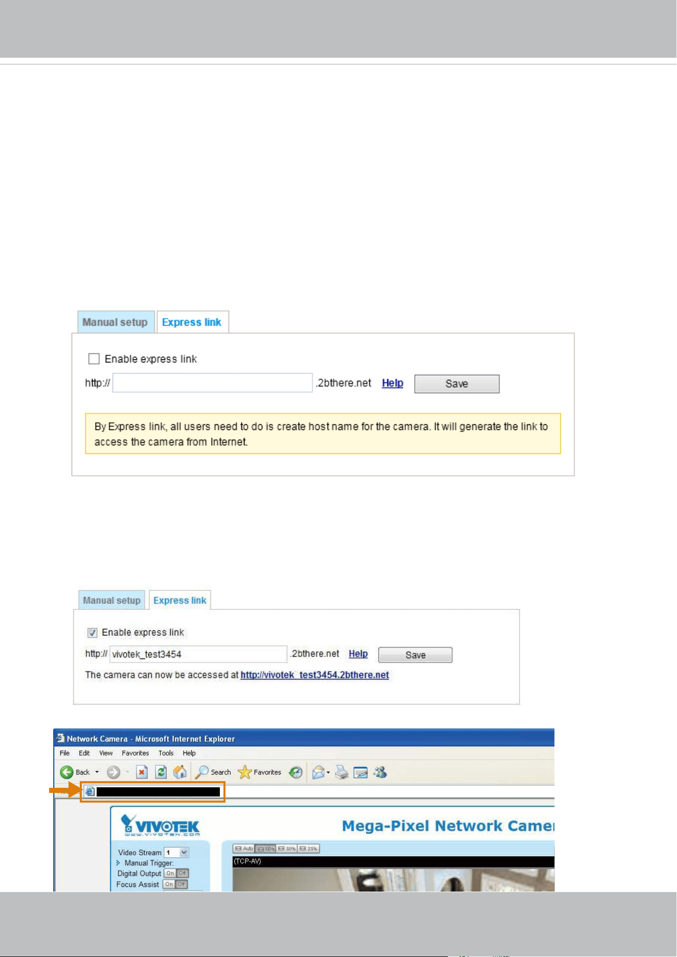
VIVOTEK
User's Manual - 93
Network > DDNS
This section explains how to configure the dynamic domain name service for the Network
Camera. DDNS is a service that allows your Network Camera, especially when assigned with a
dynamic IP address, to have a xed host and domain name.
Express link
Express Link is a free service provided by VIVOTEK server, which allows users to register a
domain name for a network device. One URL can only be mapped to one MAC address. This
service will examine if the host name is valid and automatically open a port on your router. If
using DDNS, the user has to manually congure UPnP port forwarding. Express Link is more
convenient and easier to set up.
Please follow the steps below to enable Express Link:
1. Make sure that your router supports UPnP port forwarding and it is activated.
2. Check Enable express link.
3. Enter a host name for the network device and click Save. If the host name has been used by another
device, a warning message will show up. If the host name is valid, it will display a message as shown
below.
https://vivotek_test3454.2bthere.net
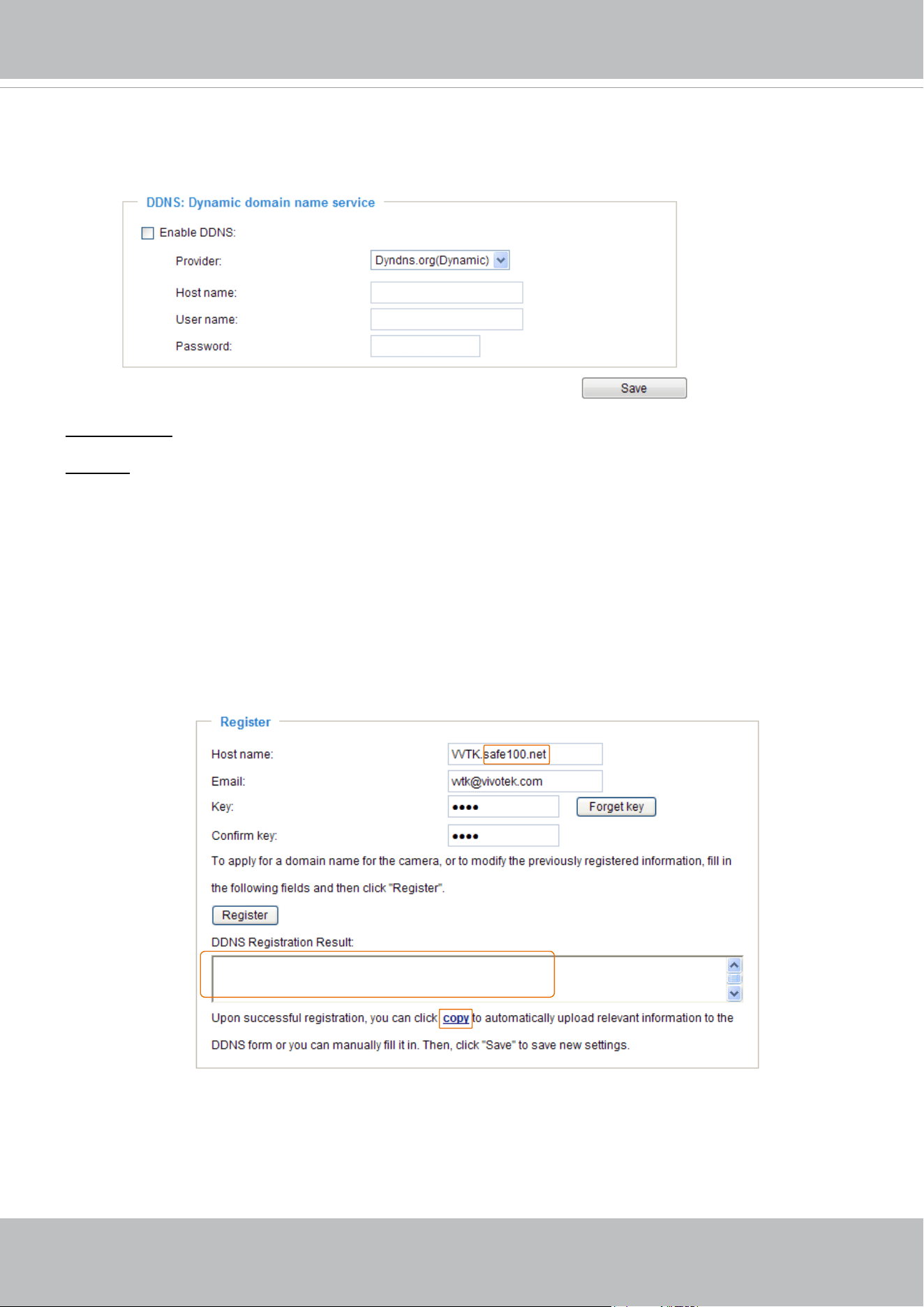
VIVOTEK
94 - User's Manual
Manual setup
DDNS: Dynamic domain name service
Enable DDNS: Select this option to enable the DDNS setting.
Provider: Select a DDNS provider from the provider drop-down list.
VIVOTEK offers
Safe100.net, a free dynamic domain name service, to VIVOTEK customers. It is
recommended that you register
Safe100.net to access VIVOTEK’s Network Cameras from the Internet.
Additionally, we offer other DDNS providers, such as Dyndns.org(Dynamic), Dyndns.org(Custom),
CustomSafe100, dyn-interfree.it.
Note that before utilizing this function, please apply for a dynamic domain account rst.
■
Safe100.net
1. In the DDNS column, select Safe100.net from the drop-down list. Click I accept after reviewing the
terms of the Service Agreement.
2. In the Register column, ll in the Host name (xxxx.safe100.net), Email, Key, and Conrm Key, and
click Register. After a host name has been successfully created, a success message will be displayed
in the DDNS Registration Result column.
3. Click Copy and all the registered information will automatically be uploaded to the corresponding elds
in the DDNS column at the top of the page as seen in the picture.
[Register] Successfully Your account information has
been mailed to registered e-mail address
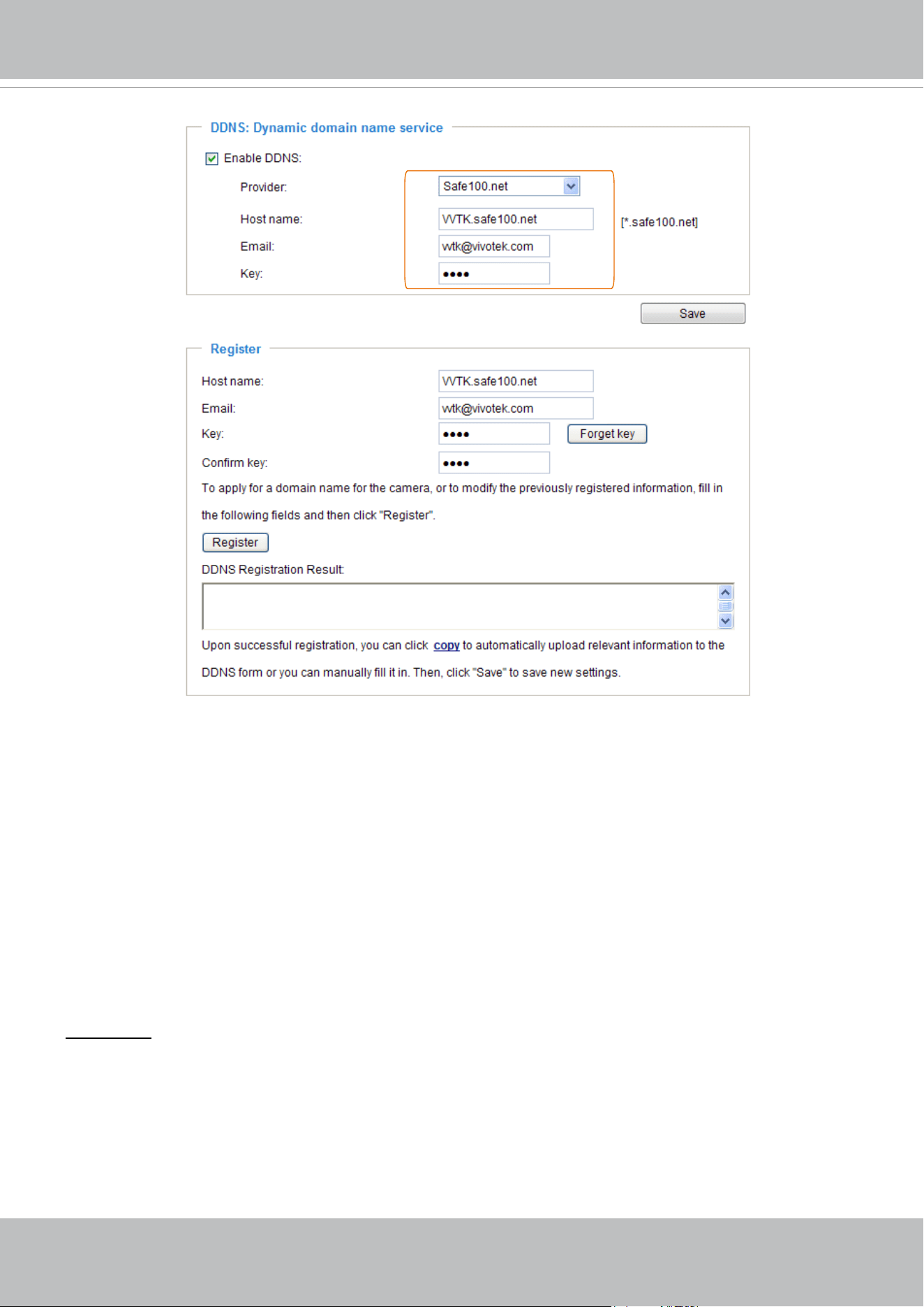
VIVOTEK
User's Manual - 95
[Register] Successfully Your account information has
been mailed to registered e-mail address
4. Select Enable DDNS and click Save to enable the setting.
■
CustomSafe100
VIVOTEK offers documents to establish a CustomSafe100 DDNS server for distributors and system
integrators. You can use CustomSafe100 to register a dynamic domain name if your distributor or system
integrators offer such services.
1. In the DDNS column, select CustomSafe100 from the drop-down list.
2. In the Register column, ll in the Host name, Server name, Email, Key, and Conrm Key; then click
Register. After a host name has been successfully created, you will see a success message in the
DDNS Registration Result column. Enter
ns1.safe100.net as the Server name.
3. Click Copy and all for the registered information will be uploaded to the corresponding elds in the
DDNS column.
4. Select Enable DDNS and click Save to enable the setting.
Forget key: Click this button if you have forgotten the key to Safe100.net or CustomSafe100. Your
account information will be sent to your email address.
Refer to the following links to apply for a dynamic domain account when selecting other DDNS
providers:
■
Dyndns.org(Dynamic) / Dyndns.org(Custom): visit http://www.dyndns.com/
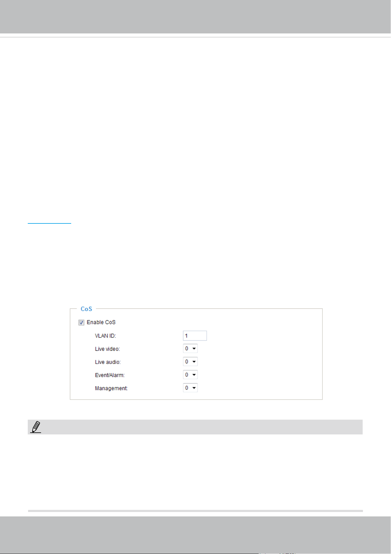
VIVOTEK
96 - User's Manual
Network > QoS (Quality of Service)
Quality of Service refers to a resource reservation control mechanism, which guarantees a certain quality
to different services on the network. Quality of service guarantees are important if the network capacity
is insufcient, especially for real-time streaming multimedia applications. Quality can be dened as, for
instance, a maintained level of bit rate, low latency, no packet dropping, etc.
The following are the main benets of a QoS-aware network:
■
The ability to prioritize trafc and guarantee a certain level of performance to the data ow.
■
The ability to control the amount of bandwidth each application may use, and thus provide higher
reliability and stability on the network.
Requirements for QoS
To utilize QoS in a network environment, the following requirements must be met:
■
All network switches and routers in the network must include support for QoS.
■
The network video devices used in the network must be QoS-enabled.
QoS models
CoS (the VLAN 802.1p model)
IEEE802.1p defines a QoS model at OSI Layer 2 (Data Link Layer), which is called CoS, Class of
Service. It adds a 3-bit value to the VLAN MAC header, which indicates the frame priority level from 0
(lowest) to 7 (highest). The priority is set up via a web console with the network switches, which then use
different queuing disciplines to forward the packets.
Below is the setting column for CoS. Enter the VLAN ID of your switch (0~4095) and choose the priority
for each application (0~7).
If you assign Video the highest level, the switch will handle video packets rst.
► A VLAN Switch (802.1p) is required. Web browsing may fail if the CoS setting is incorrect.
► Class of Service technologies do not guarantee a level of service in terms of bandwidth and delivery
time; they offer a "best-effort." Users can think of CoS as "coarsely-grained" trafc control and QoS as
"nely-grained" trafc control.
► Although CoS is simple to manage, it lacks scalability and does not offer end-to-end guarantees since
it is based on L2 protocol.
NOTE:
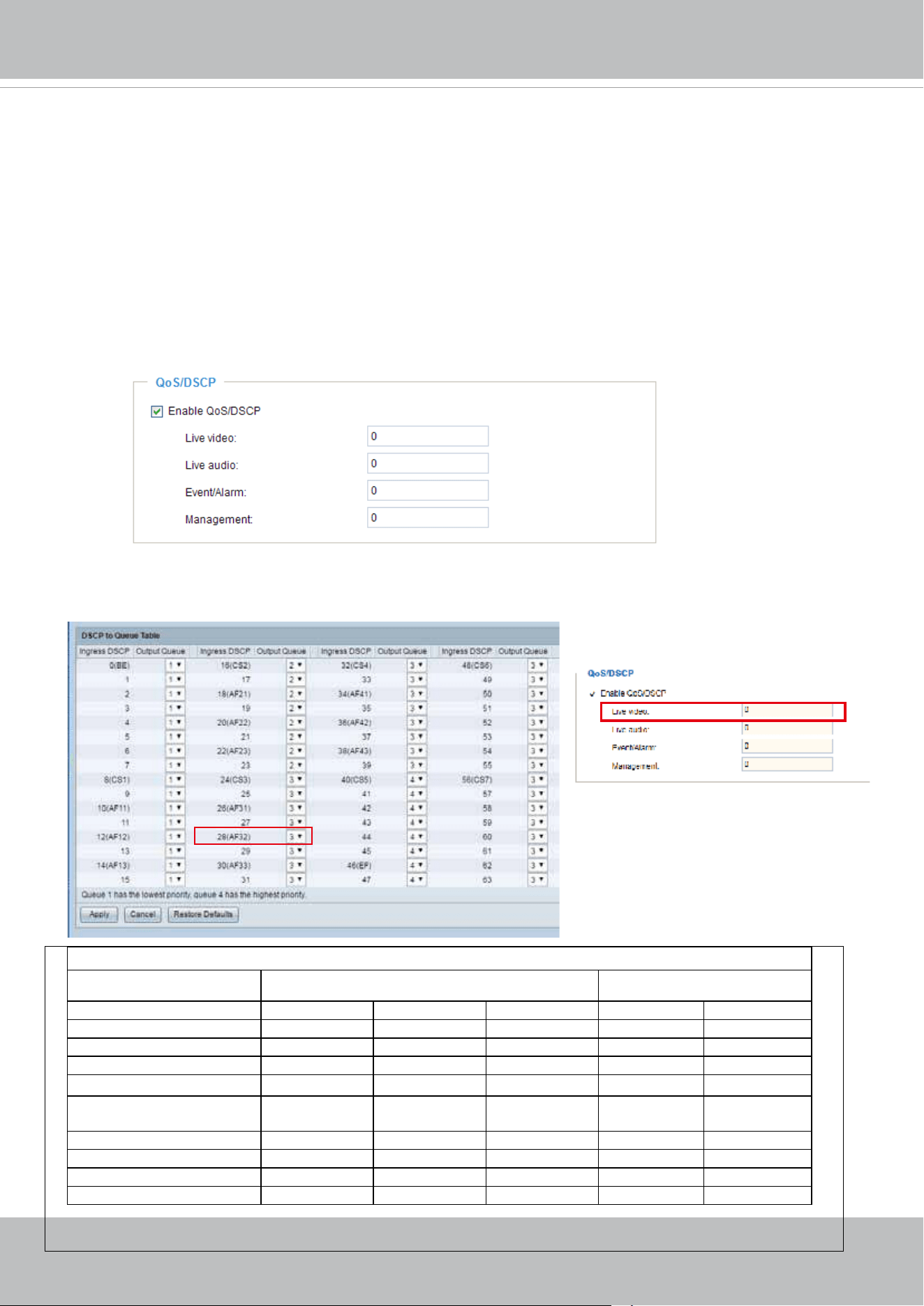
VIVOTEK
User's Manual - 97
QoS/DSCP (the DiffServ model)
DSCP-ECN defines QoS at Layer 3 (Network Layer). The Differentiated Services (DiffServ) model is
based on packet marking and router queuing disciplines. The marking is done by adding a eld to the
IP header, called the DSCP (Differentiated Services Codepoint). This is a 6-bit field that provides 64
different class IDs. It gives an indication of how a given packet is to be forwarded, known as the Per Hop
Behavior (PHB). The PHB describes a particular service level in terms of bandwidth, queueing theory,
and dropping (discarding the packet) decisions. Routers at each network node classify packets according
to their DSCP value and give them a particular forwarding treatment; for example, how much bandwidth
to reserve for it.
Below are the setting options of DSCP (DiffServ Codepoint). Specify the DSCP value for each application
(0~63).
Note that different vendors of network devices might have different methodologies and unique
implementations. Shown below is a sample corresponding information from a Cisco switch. You
should enter a DSCP tag value according to the information provided by the network devices.
32
QoS Baseline/Technical Marketing Classication and Marking Recommendations
Application Layer3 Classication Layer 2 CoS/MPLS EXP
IPP PHB DSCP
IP Routing 6 CS6 48 6
Voice 5 EF 46 5
Interactive Video 4 AF41 34 4 QoS B
Streaming-Video 4 CS4 32 4
Locally-dened Mission-
Critical Data
3 - 25 3
Call-signaling 3 AF31/CS3 26/24 3
Transactional Data 2 AF21 18 2
Network Management 2 CS2 16 2
Bulk Data 1 AF11 10 1
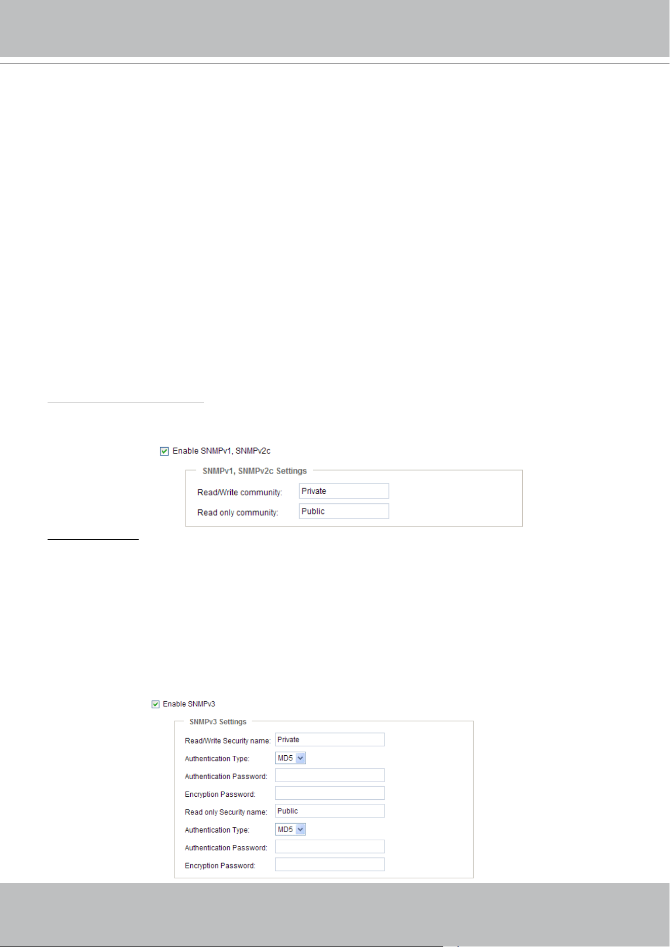
VIVOTEK
98 - User's Manual
Network > SNMP
(Simple Network Management Protocol)
This section explains how to use the SNMP on the network camera. The Simple Network
Management Protocol is an application layer protocol that facilitates the exchange of
management information between network devices. It helps network administrators to remotely
manage network devices and nd, solve network problems with ease.
■ The SNMP consists of the following three key components:
1. Manager: Network-management station (NMS), a server which executes applications that monitor and
control managed devices.
2. Agent: A network-management software module on a managed device which transfers the status of
managed devices to the NMS.
3. Managed device: A network node on a managed network. For example: routers, switches, bridges,
hubs, computer hosts, printers, IP telephones, network cameras, web server, and database.
Before conguring SNMP settings on the this page, please enable your NMS rst.
SNMP Conguration
Enable SNMPv1, SNMPv2c
Select this option and enter the names of Read/Write community and Read Only community according to
your NMS settings.
Enable SNMPv3
This option contains cryptographic security, a higher security level, which allows you to set the
Authentication password and the Encryption password.
■ Security name: According to your NMS settings, choose Read/Write or Read Only and enter the
community name.
■ Authentication type: Select MD5 or SHA as the authentication method.
■ Authentication password: Enter the password for authentication (at least 8 characters).
■ Encryption password: Enter a password for encryption (at least 8 characters).
VIVOTEK
User's Manual - 99
You can FTP the camera’s IP address to download videos recorded in the SD card, or use the “http://ip/
cgi-bin/admin/lsctrl.cgi?cmd=search
” command to examine the recorded les on your SD card.
Tips:
Network > FTP
The newer firmware disabled the FTP port for security concerns. You can manually enable the FTP
server service to enable the FTP function. You can disable the FTP server function when it is not in use.
FTP port: The FTP server allows the user to save recorded video clips. You can utilize VIVOTEK's
Shepherd utility to upgrade the rmware via FTP server. By default, the FTP port is set to 21. It can also
be assigned to another port number between 1025 and 65535.
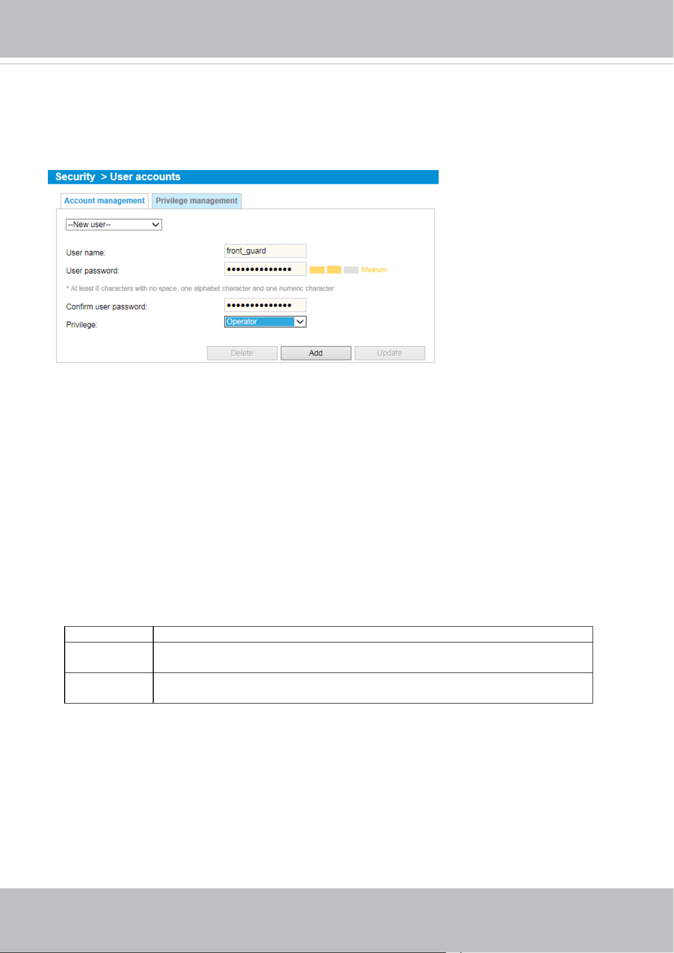
VIVOTEK
100 - User's Manual
Security > User accounts
This section explains how to enable password protection and create multiple accounts.
Account management
The administrator account name is “root”, which is permanent and can not be deleted. If you want to add
more accounts in the Account management window, please apply the password for the “root” account
rst.
The administrator can create up to 20 user accounts.
To create a new user,
1. Click to unfold the pull-down menu. Select New user.
2. Enter the new user’s name and password. Type the password identically in both text boxes.
Some, but not all special ASCII characters are supported: !, $, %, -, ., @, ^, _, and ~.
You can use them in the password combination.
The strength of your password combination is shown on the right, use the combination of alphabetic,
numeric, upper case, and lower case characters until the password strength is good enough.
3. Select the privilege level for the new user account. Click Add to enable the setting.
The privilege levels are listed below:
Administrator Full control
Operator Control DO, white-light illuminator, snapshot, and PTZ;
unable to enter the camera Conguration page.
Viewer Control DO, white-light illuminator, view, listen, PTZ, and talk through the
camera interface.
Access rights are sorted by user privilege (Administrator, Operator, and Viewer). Only administrators
can access the Conguration page. Although operators cannot access the Conguration page, they can
use the URL Commands to get and set the value of parameters. For more information, please refer to
URL Commands of the Network Camera on page 157. Viewers can only access the main page for live
viewing.
Here you also can change a user’s access rights or delete user accounts.
1. Select an existing account to modify.
2. Make necessary changes and click Update or Delete to enable the setting.
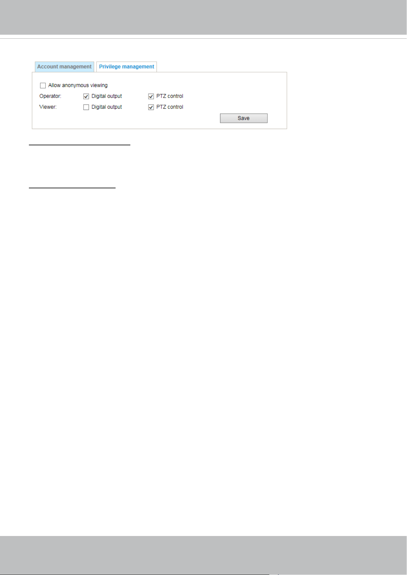
VIVOTEK
User's Manual - 101
Privilege management
Digital Output & PTZ control: You can modify the management privilege as operators or viewers.
Select or de-select the checkboxes, and then click Save to enable the settings. If you give Viewers the
privilege, Operators will also have the ability to control the Network Camera through the main page.
(Please refer to Conguration on page 36).
Allow anonymous viewing: If you select this item, any client can access the live stream without entering
a User ID and Password.

VIVOTEK
102 - User's Manual
Security > HTTPS
(Hypertext Transfer Protocol over SSL)
This section explains how to enable authentication and encrypted communication over SSL
(Secure Socket Layer). It helps protect streaming data transmission over the Internet on higher
security level.
Create and Install Certicate Method
Before using HTTPS for communication with the Network Camera, a Certicate must be created rst.
There are three ways to create and install a certicate:
Create self-signed certificate
1. Select this option from a pull-down menu.
2. In the rst column, select Enable HTTPS secure connection, then select a connection option: “HTTP
& HTTPS” or “HTTPS only”.
3. Click Create certicate to generate a certicate.
4. The Certicate Information will automatically be displayed as shown below. You can click Certicate
properties to view detailed information about the certicate.
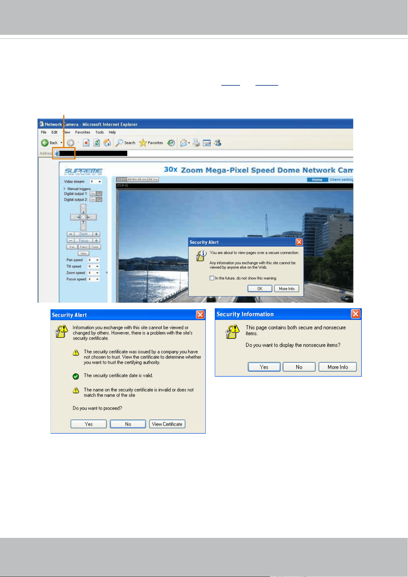
VIVOTEK
User's Manual - 103
5. Click Save to preserve your conguration, and your current session with the camera will change to the
encrypted connection.
6. If your web session does not automatically change to an encrypted HTTPS session, click Home to re-
turn to the main page. Change the URL address from “
http://” to “https://“ in the address bar and press
Enter on your keyboard. Some Security Alert dialogs will pop up. Click OK or Yes to enable HTTPS.
https://192.168.5.151/index.html
https://
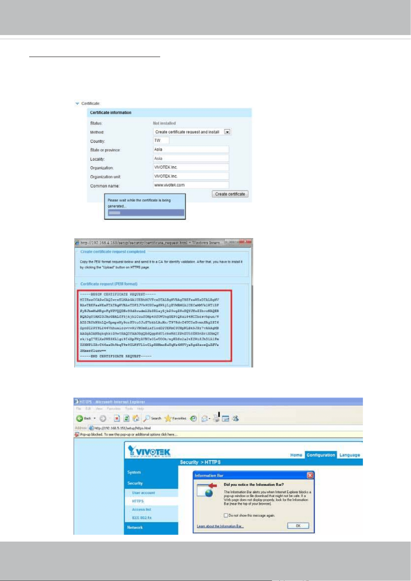
VIVOTEK
104 - User's Manual
Create certificate request and install
1. Select the option from the Method pull-down menu.
2. Click Create certicate to proceed.
3. The following information will show up in a pop-up window after clicking Create. Then click Save to
generate the certicate request.
4. The Certicate request window will prompt.
If you see the following Information bar, click OK and click on the Information bar at the top of the page
to allow pop-ups.
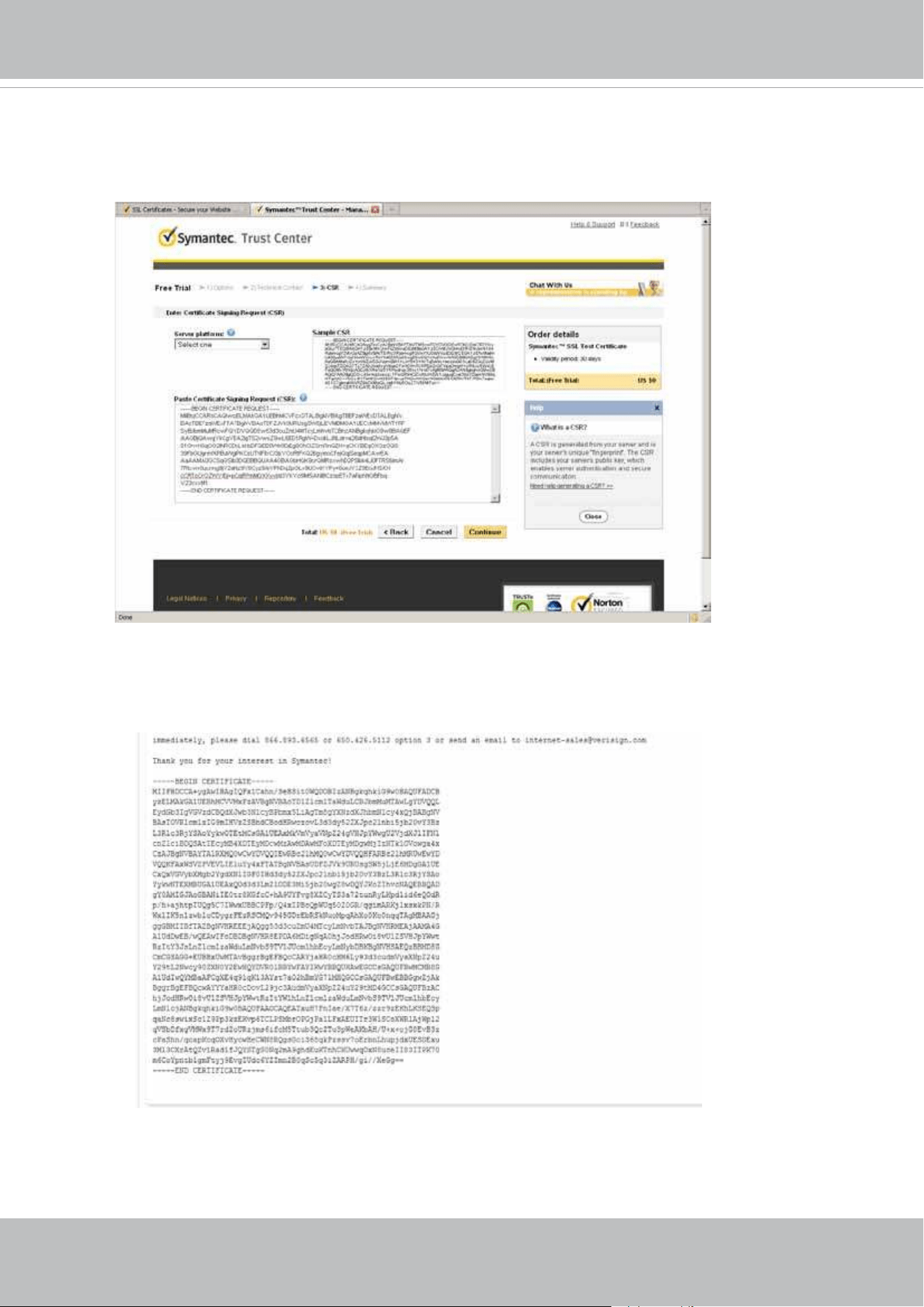
VIVOTEK
User's Manual - 105
5. Look for a trusted certificate authority, such as Symantec’s VeriSign Authentication Services, that
issues digital certificates. Sign in and purchase the SSL certification service. Copy the certificate
request from your request prompt and paste it in the CA’s signing request window. Proceed with the
rest of the process as CA’s instructions on their webpage.
6. Once completed, your SSL certicate should be delivered to you via an email or other means. Copy
the contents of the certicate in the email and paste it in a text/HTML/hex editor/converter, such as
IDM Computer Solutions’ UltraEdit.
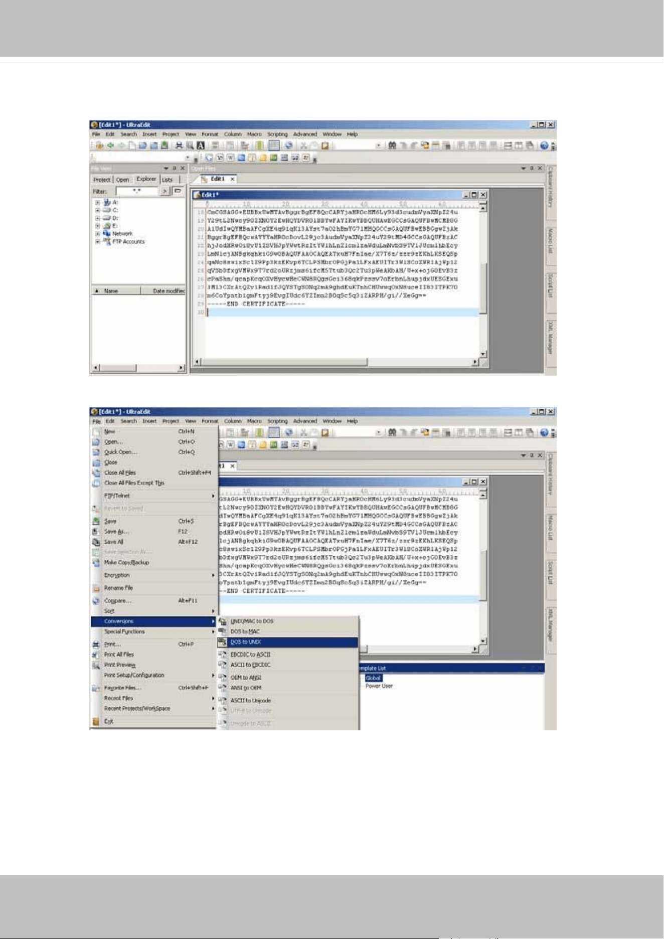
VIVOTEK
106 - User's Manual
7. Open a new edit, paste the certicate contents, and press ENTER at the end of the contents to add an
empty line.
8. Convert le format from DOS to UNIX. Open File menu > Conversions > DOS to Unix.
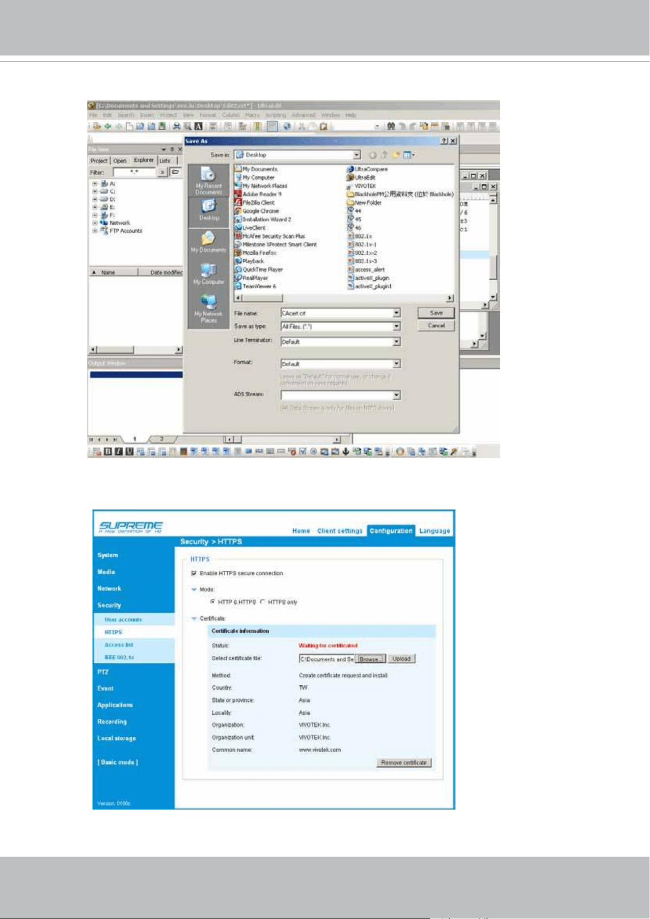
VIVOTEK
User's Manual - 107
9. Save the edit using the “.crt” extension, using a le name like “CAcert.crt.”
10. Return to the original rmware session, use the Browse button to locate the crt certicate le, and
click Upload to enable the certication.
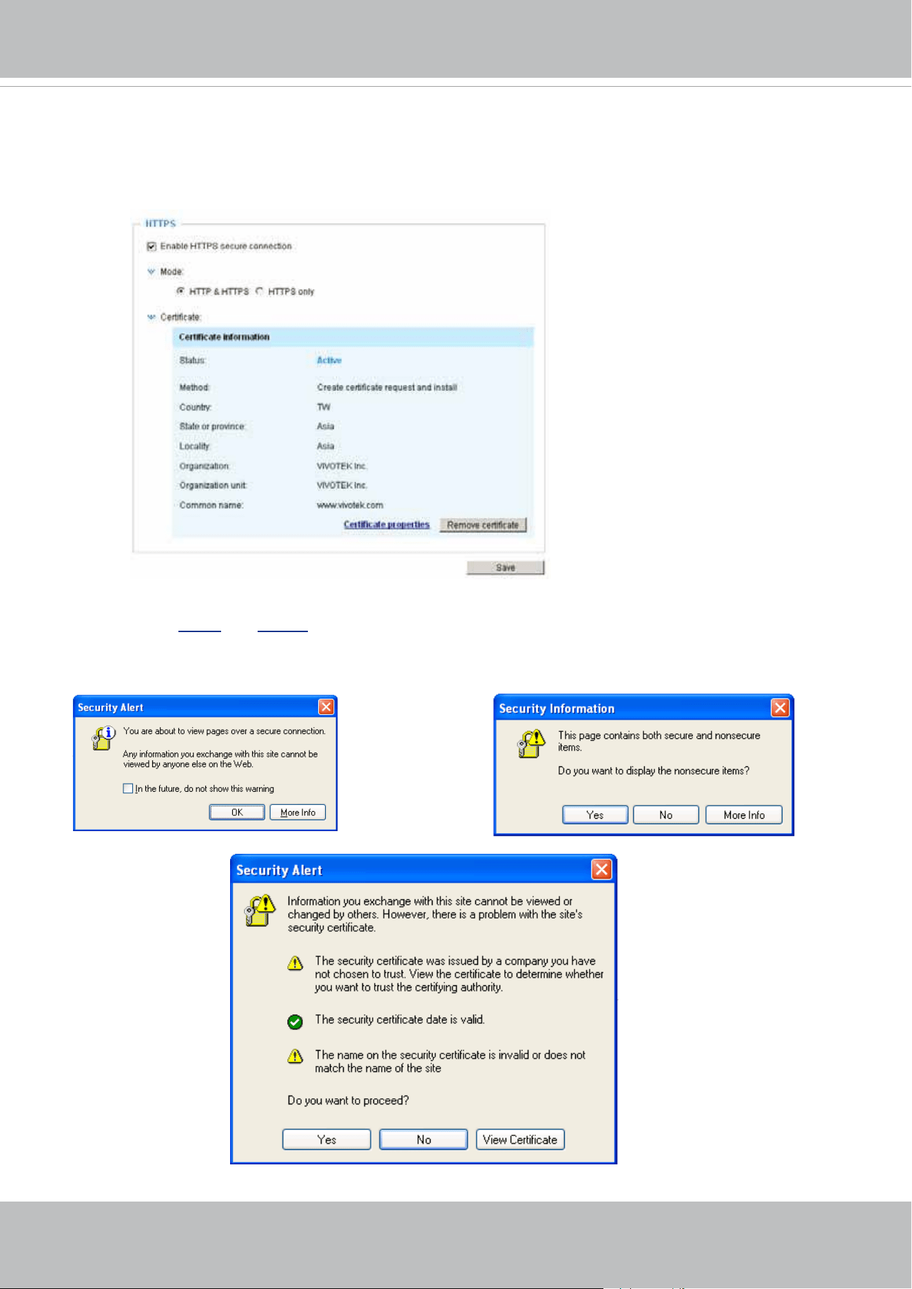
VIVOTEK
108 - User's Manual
11. When the certifice file is successfully loaded, its status will be stated as Active.
Note that a
certicate must have been created and installed before you can click on the “Save" button for
the conguration to take effect.
12.To begin an encrypted HTTPS session, click Home to return to the main page. Change the URL ad-
dress from “
http://” to “https://“ in the address bar and press Enter on your keyboard. Some Security
Alert dialogs will pop up. Click OK or Yes to enable HTTPS.
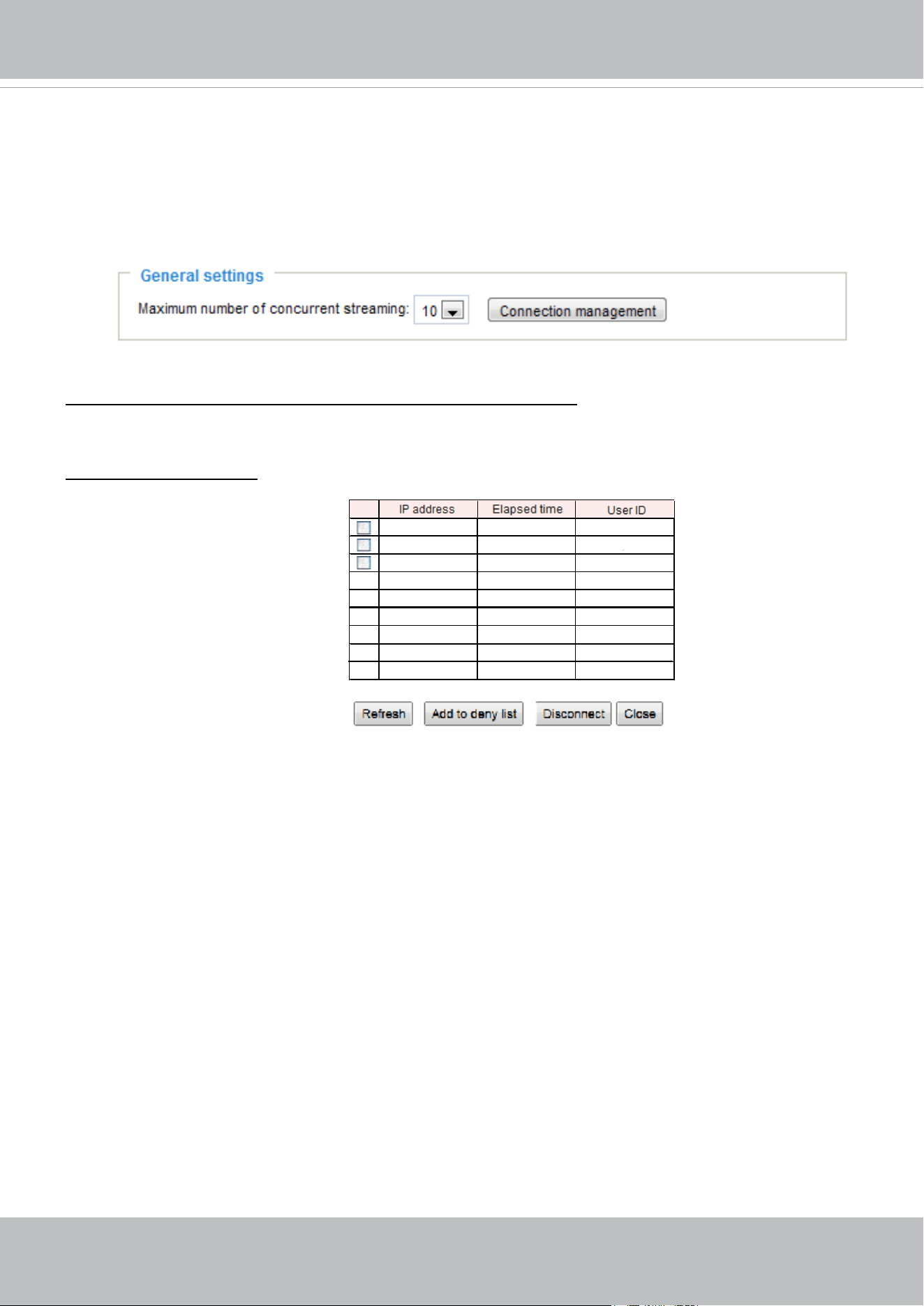
VIVOTEK
User's Manual - 109
Security > Access List
This section explains how to control access permission by verifying the client PC’s IP address.
General Settings
Maximum number of concurrent streaming connection(s) limited to: Simultaneous live viewing for 1~10
clients (including all streams). The default value is 10. If you modify the value and click Save, all current
connections will be disconnected and automatically attempt to re-link (IE Explorer or Quick Time Player).
Connection management: Click this button to display the connection status window showing a list of the
current connections. For example:
■ IP address: Current connections to the Network Camera.
■ Elapsed time: How long the client has been at the live view webpage (note that only clients currently at
the live view window will be listed here).
■ User ID: If the administrator has set a password for the webpage, the clients have to enter a user name
and password to access the live video. The user name will be displayed in the User ID column. If the
administrator allows clients to make a connection without a user name and password, the User ID
column will be empty.
There are some situations which allow clients access to the live video without a user name and
password:
1. The administrator does not set up a root password. For more information about how to set up a root
password and manage user accounts, please refer to Security > User account on page 100.
2. The administrator has set up a root password, but set RTSP Authentication to “disable“. For more
information about RTSP Authentication, please refer to RTSP Streaming on page 88.
3. The administrator has set up a root password, but allows anonymous viewing. For more information
about Allow Anonymous Viewing, please refer to page 100.
■ Refresh: Click this button to refresh all current connections.
■ Add to deny list: You can select entries from the Connection Status list and add them to the Deny List to
deny their access. Please note that those checked connections will only be disconnected temporarily
and they will automatically retry a connection (IE Explorer or Quick Time Player). If you want to enable
the denied list, please check Enable access list ltering and click Save in the rst column.
192.168.3.25
61.22.15.3
192.168.1.147
IP address
45:00:34
00:10:09
12:20:34
Elapsed time
greg
anonymous
root
User ID
Add to Deny List DisconnectRefresh
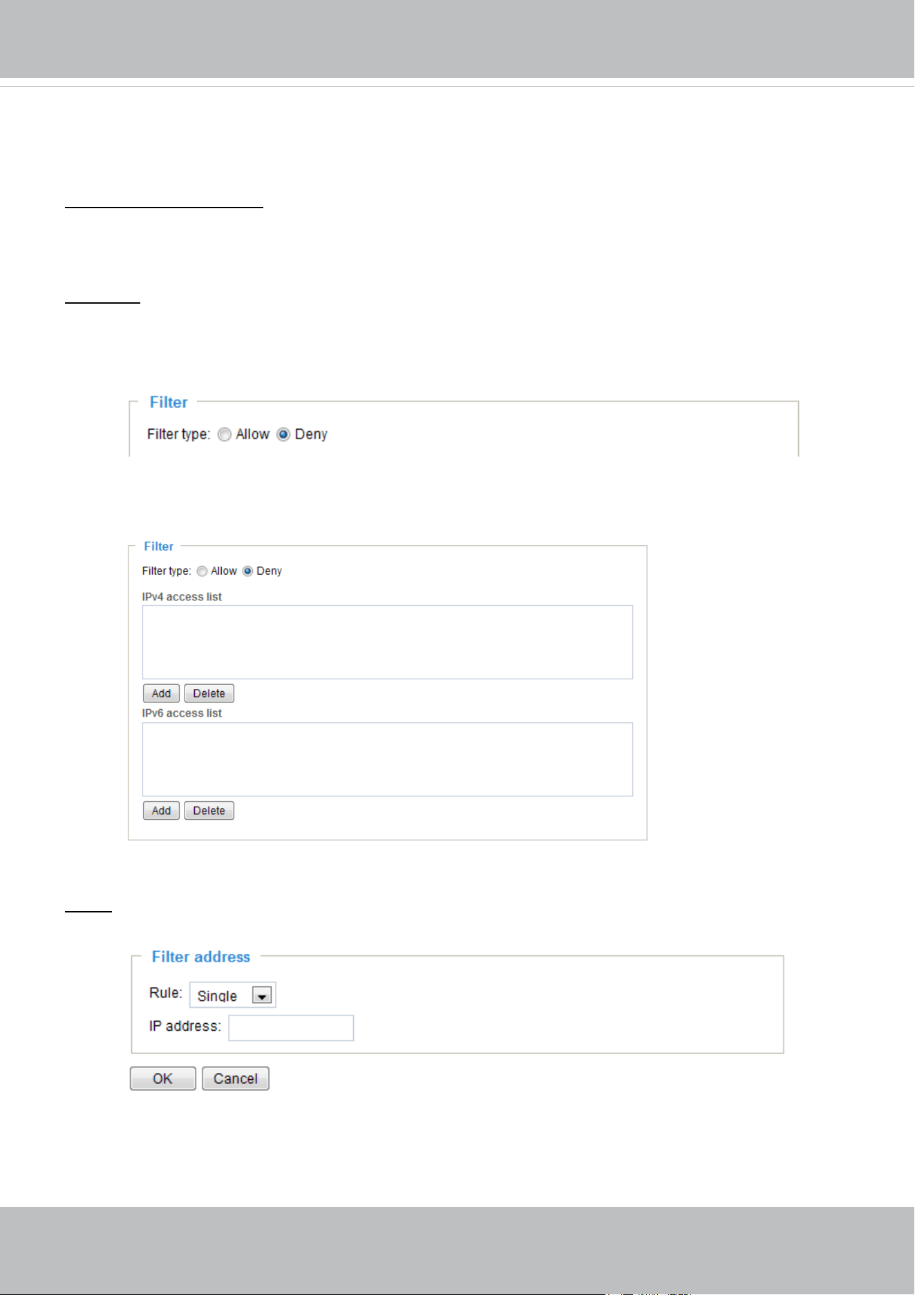
VIVOTEK
110 - User's Manual
■ Disconnect: If you want to break off the current connections, please select them and click this button.
Please note that those checked connections will only be disconnected temporarily and they will
automatically retry a connection (IE Explore or Quick Time Player).
Enable access list ltering: Check this item and click Save if you want to enable the access list ltering
function.
Filter
Filter type: Select Allow or Deny as the lter type. If you choose Allow Type, only those clients whose
IP addresses are on the Access List below can access the Network Camera, and exclude the access
from those that are not on the list. If you choose Deny Type, those clients whose IP addresses are on
the Access List below will not be allowed to access the Network Camera, while those that are not on the
list can.
Then you can Add a rule to the following Access List. Please note that the IPv6 access list column
will not be displayed unless you enable IPv6 on the Network page. For more information about IPv6
Settings, please refer to Network > Enable IPv6 on page 84 for detailed information.
There are three types of rules:
Single: This rule allows the user to add an IP address to the Allowed/Denied list.
For example:
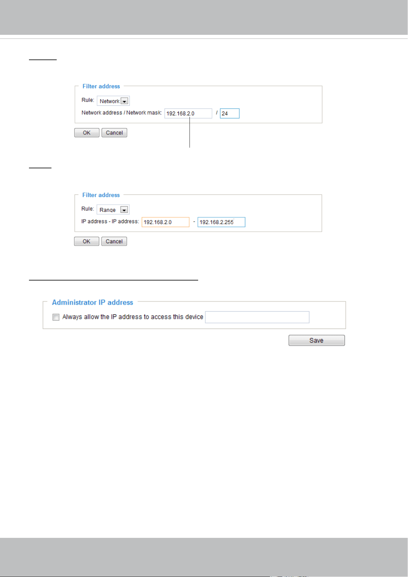
VIVOTEK
User's Manual - 111
Network: This rule allows the user to assign a network address and corresponding subnet mask to the
Allow/Deny List in the CIDR format, e.g. 192.168.xx.xx/24.
For example:
Range: This rule allows the user to assign a range of IP addresses to the Allow/Deny List.
Note: This rule is only applicable to IPv4 addresses.
For example:
Administrator IP address
Always allow the IP address to access this device: You can check this item and add the Administrator’s
IP address in this eld to make sure the Administrator can always connect to the device.
IP address 192.168.2.x will be blocked.
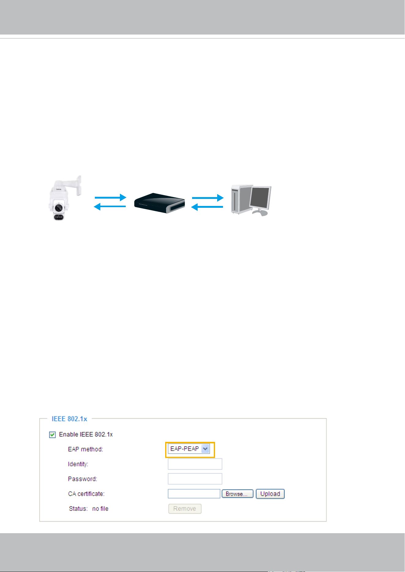
VIVOTEK
112 - User's Manual
Security > IEEE 802.1x
Enable this function if your network environment uses IEEE 802.1x, which is a port-based network
access control. The network devices, intermediary switch/access point/hub, and RADIUS server must
support and have their 802.1x settings enabled.
The 802.1x standard is designed to enhance the security of local area networks, which provides
authentication to network devices (clients) attached to a network port (wired or wireless). If all certicates
between client and server are veried, a point-to-point connection will be enabled; if authentication fails,
access on that port will be prohibited. 802.1x utilizes an existing protocol, the Extensible Authentication
Protocol (EAP), to facilitate communication.
■
The components of a protected network with 802.1x authentication:
1.
Supplicant: A client end user (camera), which requests authentication.
2.
Authenticator (an access point or a switch): A “go between” which restricts unauthorized end users
from communicating with the authentication server.
3.
Authentication server (usually a RADIUS server): Checks the client certicate and decides whether to
accept the end user’s access request.
■
VIVOTEK Network Cameras support two types of EAP methods to perform authentication: EAP-PEAP
and EAP-TLS.
Please follow the steps below to enable 802.1x settings:
1. Before connecting the Network Camera to the protected network with 802.1x, please apply a digital
certificate from a Certificate Authority (i.e., network administrator of your company) which can be
validated by a RADIUS server.
2. Connect the Network Camera to a PC or notebook outside of the protected LAN. Open the
conguration page of the Network Camera as shown below. Select EAP-PEAP or EAP-TLS as the
EAP method. In the following blanks, enter your ID and password issued by the CA, then upload
related certicate(s).
Supplicant
(Network Camera)
Authenticator
(Network Switch)
Authentication Server
(RADIUS Server)
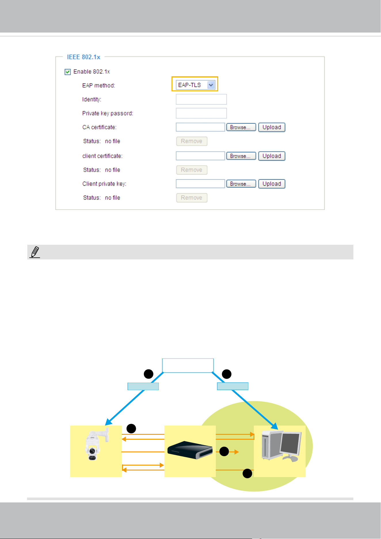
VIVOTEK
User's Manual - 113
3. When all settings are complete, move the Network Camera to the protected LAN by connecting it to an
802.1x enabled switch. The devices will then start the authentication automatically.
► Below is the authentication process for 802.1x:
1. The Certicate Authority (CA) provides the required signed certicates to the Network Camera (the
supplicant) and the RADIUS Server (the authentication server).
2. A Network Camera requests access to the protected LAN using 802.1X via a switch (the authenticator).
The client offers its identity and client certicate, which is then forwarded by the switch to the RADIUS
Server, which uses an algorithm to authenticate the Network Camera and returns an acceptance or
rejection back to the switch.
3. The switch also forwards the RADIUS Server’s certicate to the Network Camera.
4. Assuming all certificates are validated, the switch then changes the Network Camera’s state to
authorized and is allowed access to the protected network via a pre-congured port.
VIVOTEK
Network Camera
RADIUS Server
Certificate Authority
(CA)
Protected LAN
Certificate
1
1
2
3
4
Network Switch
Certificate
NOTE:
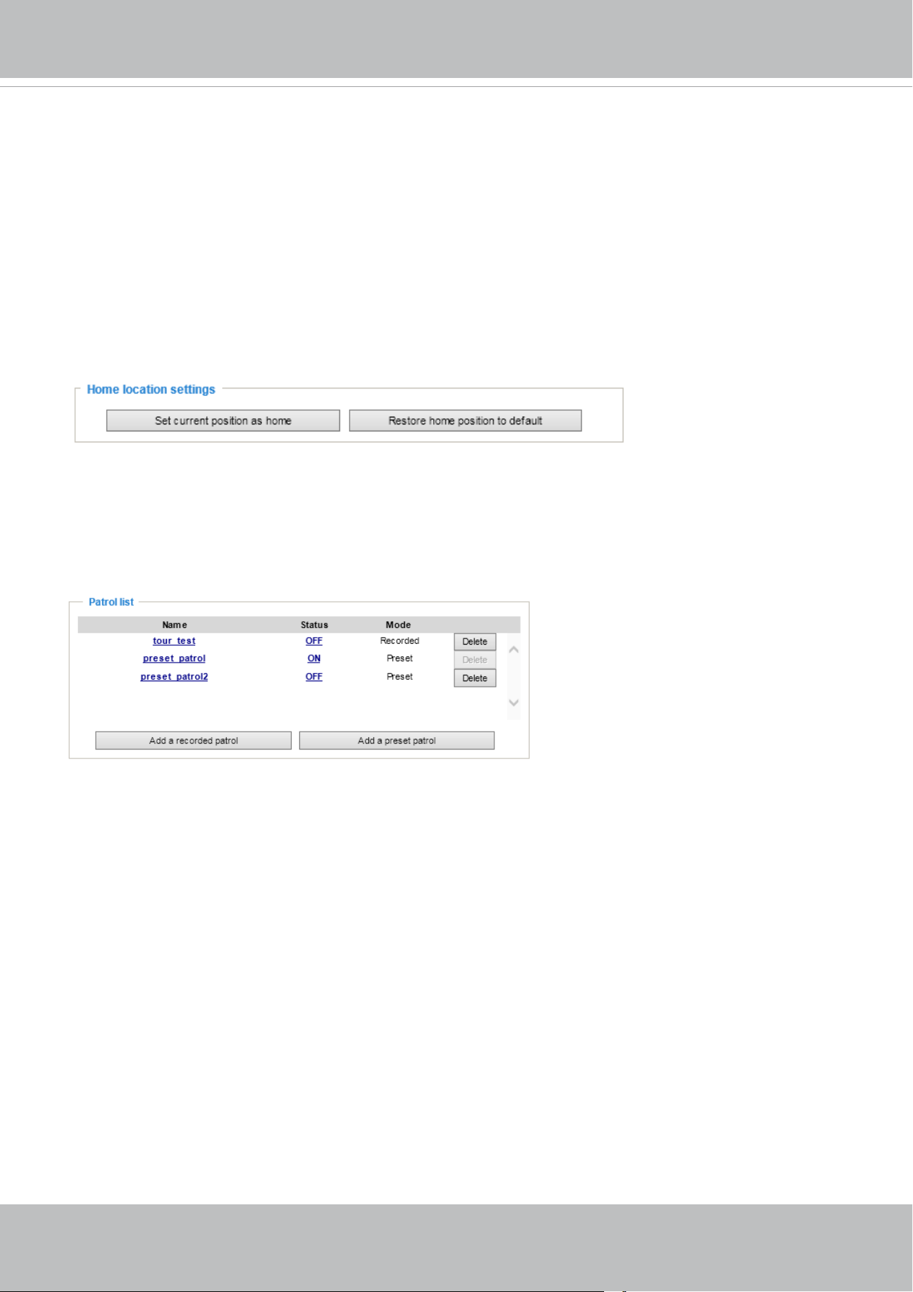
VIVOTEK
114 - User's Manual
PTZ > PTZ settings
This section explains how to control the Network Camera’s Pan/Tilt/Zoom operation. The
camera comes with built-in PTZ mechanisms.
Home location settings
Move your current field of view to a preferred location using the PTZ panel or mouse clicks
on the screen, and use the below buttons to configure the current view as the default home
position. You can also restore the home posiotion to the factory default, which is approximately
45 degree looking down with the lens lined up with the VIVOTEK logo.
Patrol list
This column displays the congured patrols. Note that only one patrol can apply at a time. Use
the ON/OFF buttons to enable/disable an existing patrol.
Use the buttons below to create a recorded patrol or a preset patrol.
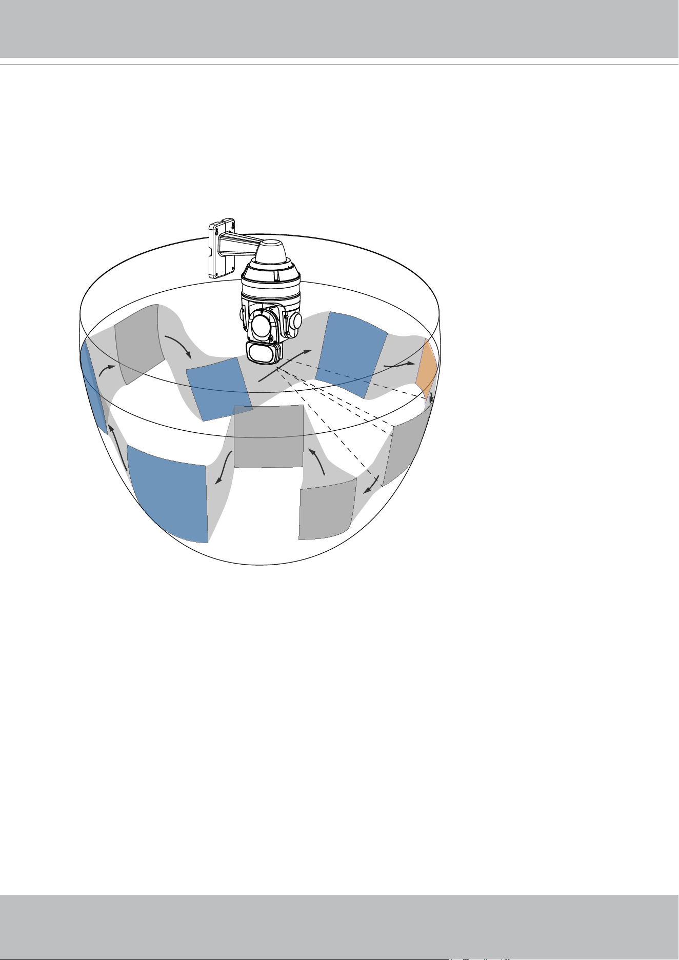
VIVOTEK
User's Manual - 115
Recorded Patrol
The recorded patrol allows you to record the process moving along interested points (positions)
in your surveillance area while the camera memorizes every Pan/Tilt/Zoom/Focus commands
you gave in the process. You can then save the process as a recorded patrol. Due to the
limitation on system memory, you can configure 4 recorded patrols, each with a length of 2
minutes.
P5
P2
P4
Stop points
P1
P6
P7
P8
P9
P3
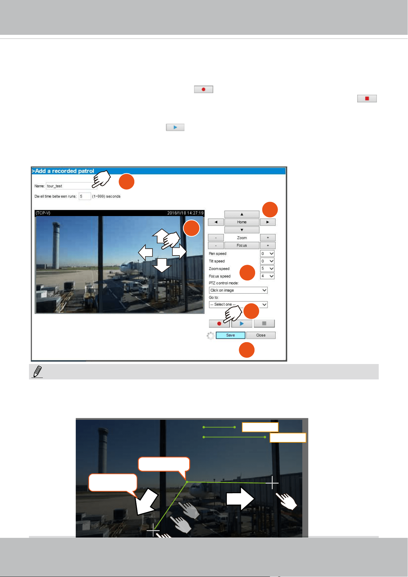
VIVOTEK
116 - User's Manual
To create a recorded patrol,
1. Enter a name for the patrol.
2. Use mouse clicks or the PTZ panel to select a eld of view as your start point.
3. Select the Pan/Tilt/Zoom/Focus speed, and the PTZ control mode.
4. You can then click on the Record button
and start to scan through your surveillance
area by moving along and staying at the points of your interest. Click the record button
again to stop the recording when you visisted all of your points of interest. Zoom and focus
during the process are also supported.
5. You can use the playback button
to review your recorded patrol before you click the
Save button. When you are satised with the recording, click Save and Close to leave the
conguration page. Note that if you start a new recording without saving the previous one,
the previous recording will be abandoned.
1
2
3
4
2
5
NOTE:
The Joystick mode simulates joystick control using your mouse. Click and hold down the left mouse
button, and move your mouse target cursor to the direction you want. Drag towards the direction you
prefer, the lens will move to that direction. You can click and hold down the mouse button to continue
scanning.
center point
Lens move
direction
Slower
Faster
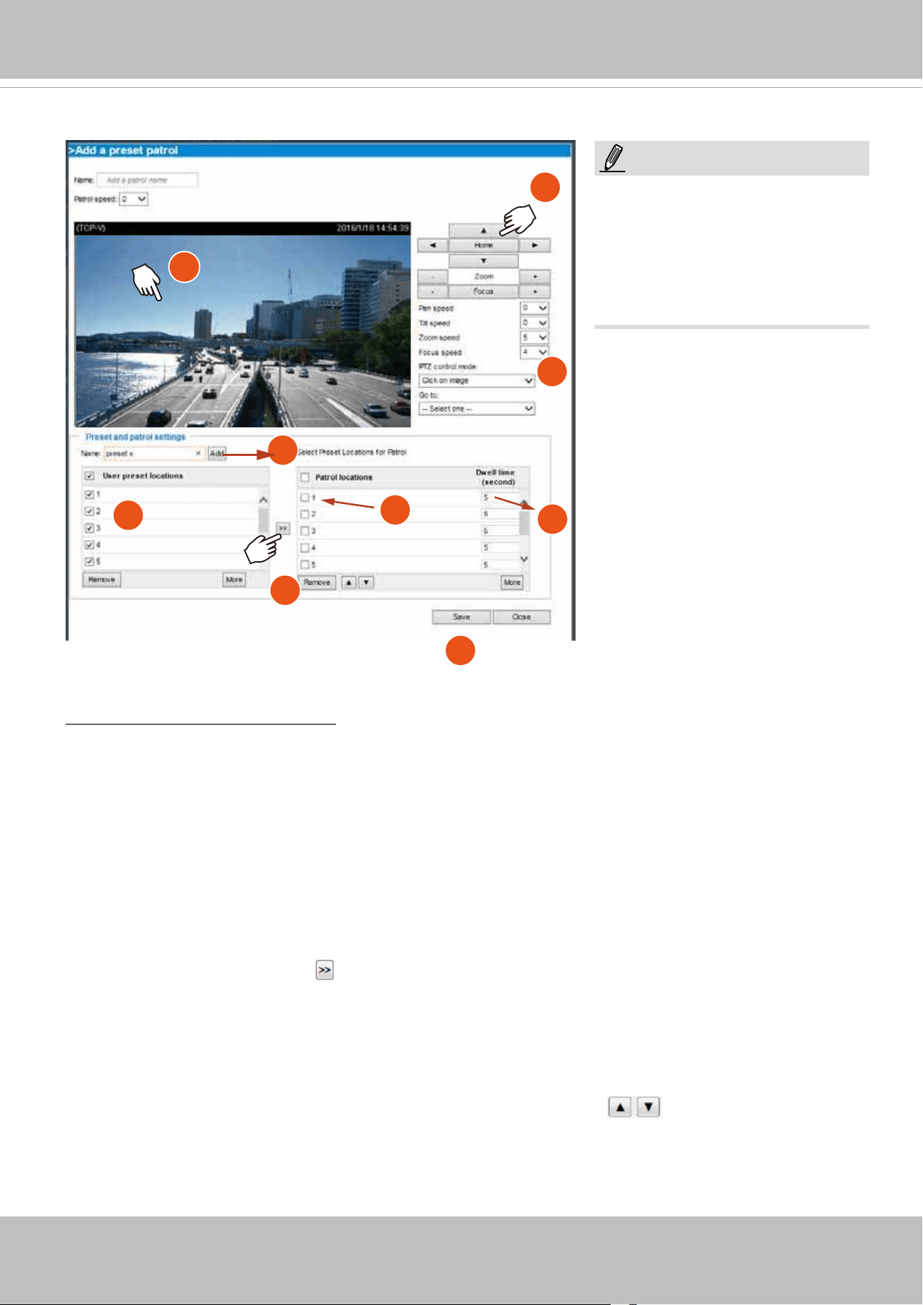
VIVOTEK
User's Manual - 117
1
1
2
3
4
5
6
7
8
NOTE:
The navigation buttons here also
support the continuous move. You
can click and hold down the button
to move across the screen until you
release the button.
Preset positions and patrol settings
In the PTZ settings page, you can congure preset positions for the camera to travel through. A total of
256 preset positions can be congured. 40 of them can be congured into one patrol.
Please follow the steps below to congure preset positions and arrange them in a pan/tilt/zoom tour:
1. Adjust the shooting area to the desired position using the keypad on the upper right side of the
window. The default Home position refers to the center position defaulted in the factory. You might as
well select another area of interest as the “Home“ position. You should also select the speeds for the
actions that occur during the patrol; i.e., pan, tilt, zoom, focus, and the auto pan/patrol.
2. Enter a name for a new preset position, which can contain up to forty characters. Click Add to enable
the settings. The preset positions will be listed on the User preset locations. (To add positions you
wish, please repeat steps 1~2.)
3. Select the preset positions and click on the Save button at the bottom of the screen.
4. Click on the move button (>>)
to move positions to the Patrol locations window.
5. You may select some or all of the imported positions as the stop points during the tour.
6. Enter a preferred dwell time before the camera lens moves to the next position.
7. Select a speed level for the auto patrol tour.
8. Click on the Save button to preserve your conguration.
To remove a preset position from the list, select it and click Remove.
You can re-arrange the patrol order of the positions on the list using the
buttons.
Preset Patrol
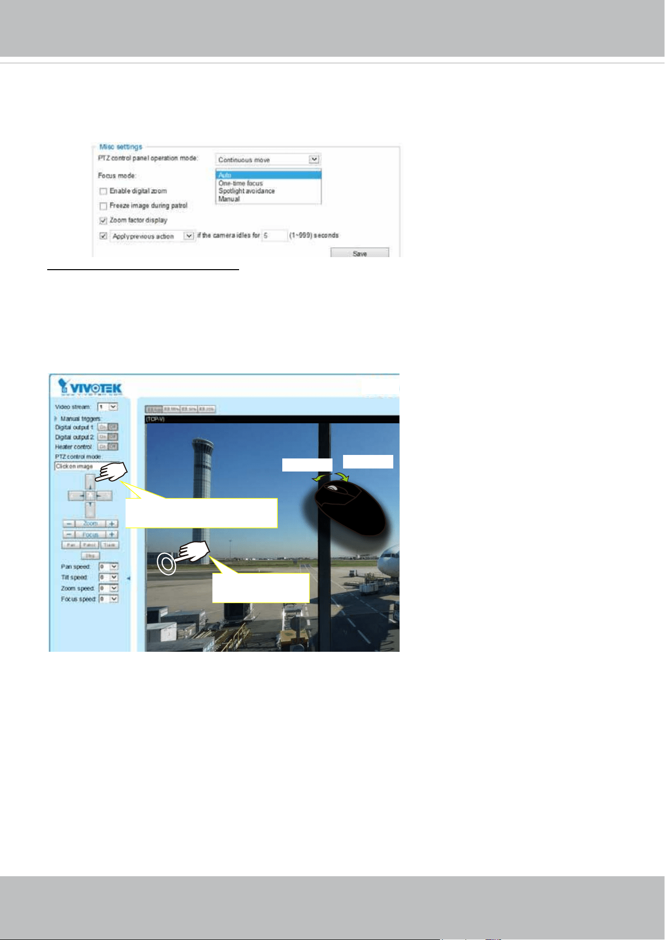
VIVOTEK
118 - User's Manual
PTZ control panel operation mode: This determines how your mouse and PTZ control panel works on a
live view window.
The Continuous move allows your screen control action to continue as long as you click and hold down
the left mouse button. For example, if you click on the left button on the PTZ control panel, the camera's
view should continuously rotate to the left until you release the button. The same applies to arrow keys,
Zoom, and Focus buttons on the PTZ panel. If you select Click to move, every single mouse click takes
effect for once without the ensuing move.
Note that if your screen control malfunctions, it is possible that the CPU of your current view station can
not cope with the HD video feeds or that an incompatibility issue occurred with the ActiveX control plug-
ins.
If you select the Enable digital zoom checkbox, you will be able to zoom in on an image by up to 960X
magnication with the combination of the 30x mechanical zoom and another 12X digital zoom.
Apply previous action if the camera idles for __(1~999) seconds: You can assign an action to be
taken when the camera sits idle for a congurable period time. For example, you can let camera resume
a patrol tour. The resumed patrol will continue from the last preset position. You may also let the camera
return to the home position. The idle state does not include the situations when the camera is performing
pan or patrol action.
Return to home position: When no activities occur after a congurable period of time, let the camera’s
lens return to the default home position.
Zoom In
Zoom Out
Click and hold down the
button to continue turning
Click to bring to
center of view
Misc. settings:
Use the checkboxes and the pull-down menus for the camera to automatically resume the previous
action or return to the home position after the camera has stayed idle for a period of time.

VIVOTEK
User's Manual - 119
If you select the Enable digital zoom checkbox, you will be able to zoom in on an image by up to 360X
magnication with the combination of the 30x mechanical zoom and another 12X digital zoom.
Focus mode: This determines how focus takes place when camera lens is ordered to aim at different
areas or preset points, or zoom in or out on a scene.
Auto: Firmware automatically adapts to different environments regarding the distances of objects in
scene, and generates the best focus results.
One-time focus: Because image blurs can occur during a repeated focusing process, once moved to
a scene (a preset point), the camera exerts only one automatic focus in this mode. This applies when
users prefer an expected depth of eld and prefer the view not to be affected by the continuous focusing
acts resulting from moving objects in the scene. The One-time focus applies when using presets and a
general imaging result is expected without focusing near and far.
Spotlight avoidance: The Spotlight avoidance mode automatically avoids the interferences of strong light
sources such as spotlights in a stadium or road lamp in a dark scene.
Manual: 1. When applied and moved to a position, a manual focus action is required.
2. The second scenario applies to the use of an intelligent video analytics software which may utiliize
an independant focusing algorithm. If such a 3rd-party software is implemented, none of the above
focus modes apply.
Zoom factor display
If you check this item, the zoom indicator will be displayed on the home page when you zoom in/out the
live viewing window
The Freeze image during patrol skips the display of the process when moving from one position to
another. Only the views of the preset points are displayed.
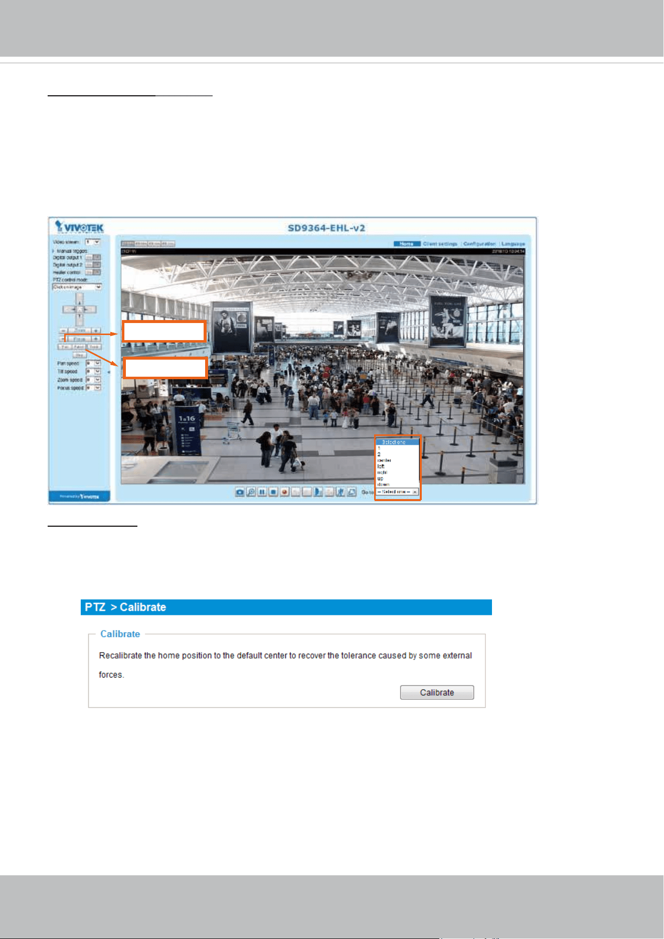
VIVOTEK
120 - User's Manual
Positions on the Home page
The Preset positions will also be displayed on the home page. Select one from the Go to drop-down
list, and the Network Camera will move to the selected position.
Pan button: Click this button to start the 360° horizontal auto pan.
Patrol button: Click this button, then the Network Camera will patrol continuously among the selected
positions.
PTZ > Calibrate
This function re-calibrates the home position to the default center to recover any displacement caused by
external forces. Please note that there is no conrm message after using the function, and the calibration
immediately takes place. If, after a long use, a user nds it is difcult to move camera’s eld of view to a
specic point, use this function to restore the camera’s orginal coordinates in pan and tilt motions.
Pan button
Patrol button
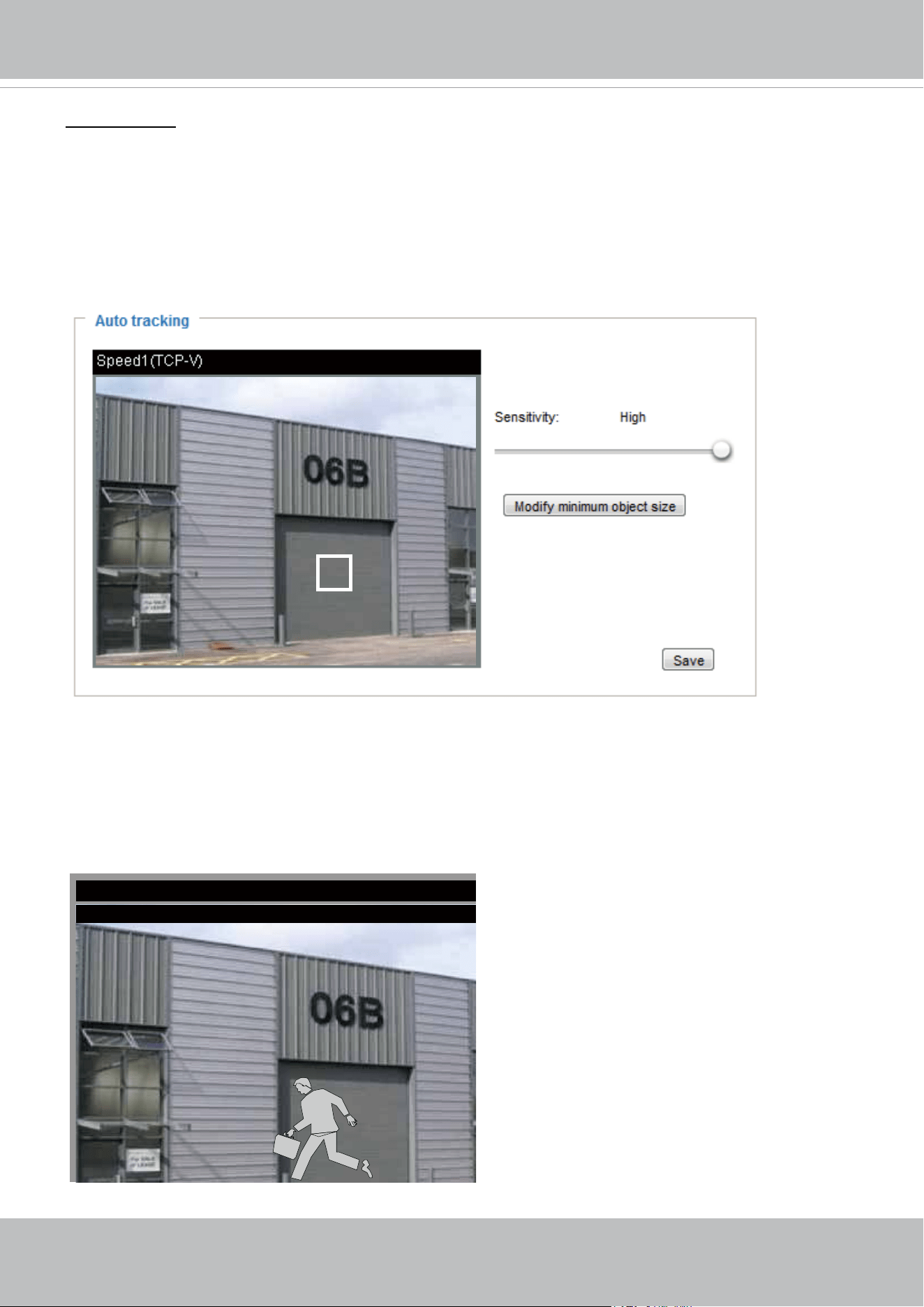
VIVOTEK
User's Manual - 121
Auto tracking
In this window, you can modify the minimum object size as the triggering factor while performing the
Auto Tracking function. You can move the camera view to an area of your interest, estimate, and dene
the possible size of objects. For example, you can designate the object size such as that of a human
trespasser. The silhouette of the tresspasser must be larger than the whole of the object size square box.
The minimum object size is 30x30 pixels within a 320x420 view window.
Use the slide bar to tune the sensitivity of the tracking function.
2014/3/2 15:28:44
This function stops when the user clicks on any buttons on the PTZ panel, or a mouse click takes place
on a view window.
Users can choose to perform other functions, such as pan or patrol, simply by clicking their buttons on
the PTZ panel while the camera is performing the auto tracking function.
SDXXXXX-VVTK(TCP-V)
Tracking.. 1.0X SDXXXXXE-VVTK 2016/03/17
When Auto Tracking is taking place, a “Tracking” message is displayed on the message bar.
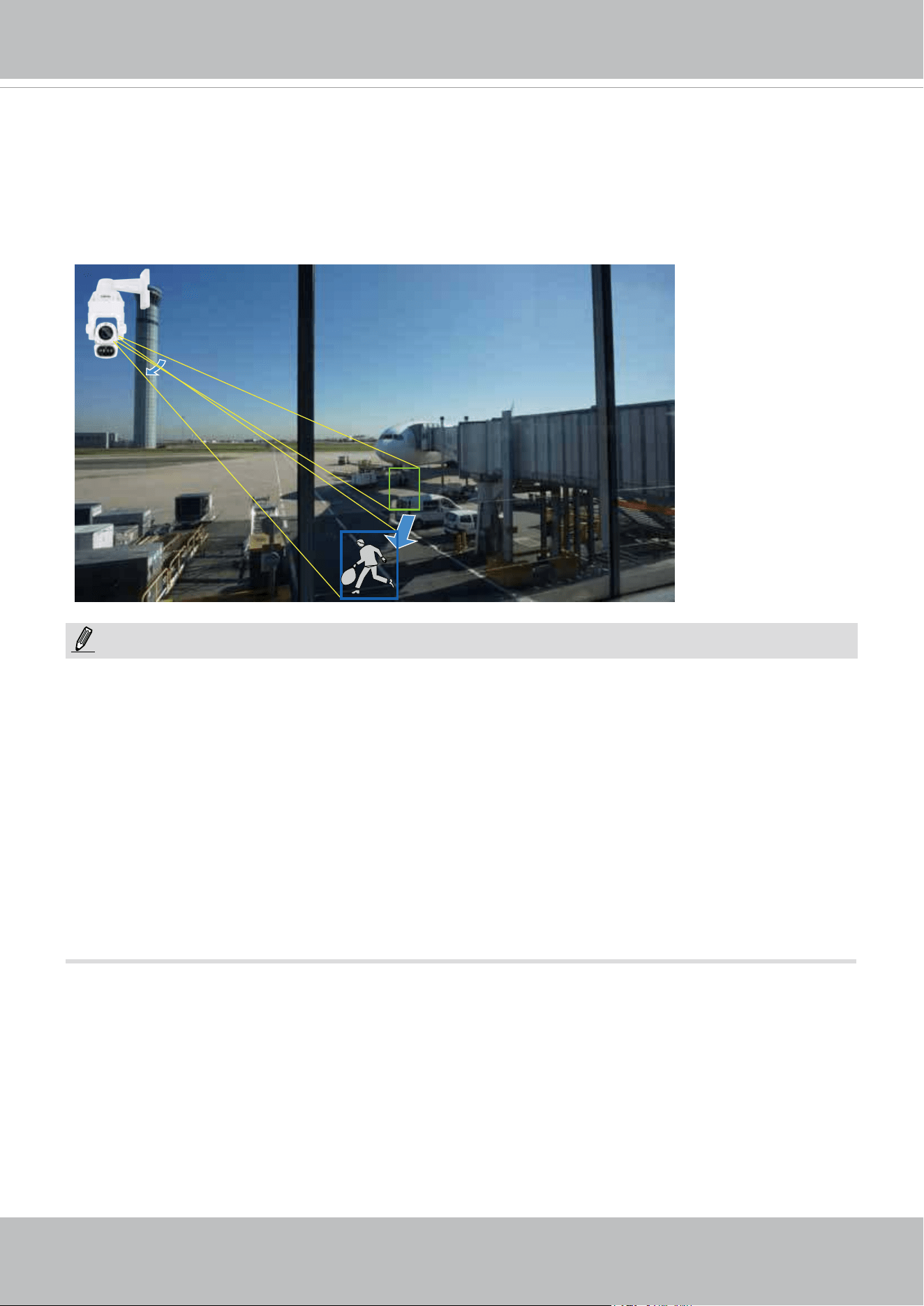
VIVOTEK
122 - User's Manual
NOTE:
The conditions for using this function are listed below:
1. The speed dome can track one object at a time.
2. If multiple objects are present in the FOV, the camera tracks the object that is farthest from
the camera.
3. If a tracked object stays motionless for 10 seconds, camera will abandon it and start tracking
another object that is farthest away from the center.
4. The zoom-in ratio while tracking is determined by the zoom ratio of the camera lens when the
tracking is triggered.
5. Manual control always has a higher priority than Auto tracking, such as using a joystick to pan
or tilt or using a click on VAST view cell.
6. Objects can easily move away from an FOV when the zoom-in ratio is high. Therefore, it is
recommended not to zoom in too much on where the Auto tracking is expected to take place.
Auto tracking is congured by designating the minimum object size. Moving objects that enter
the current region of view will trigger the tracking action.
Auto tracking, if applied, is designed to track an intruder in a place where human trafc is not
heavy, such as a warehouse or a load area. Heavy trafc can result in a constant shift of tracked
objects, and reduce the effectiveness of the feature.
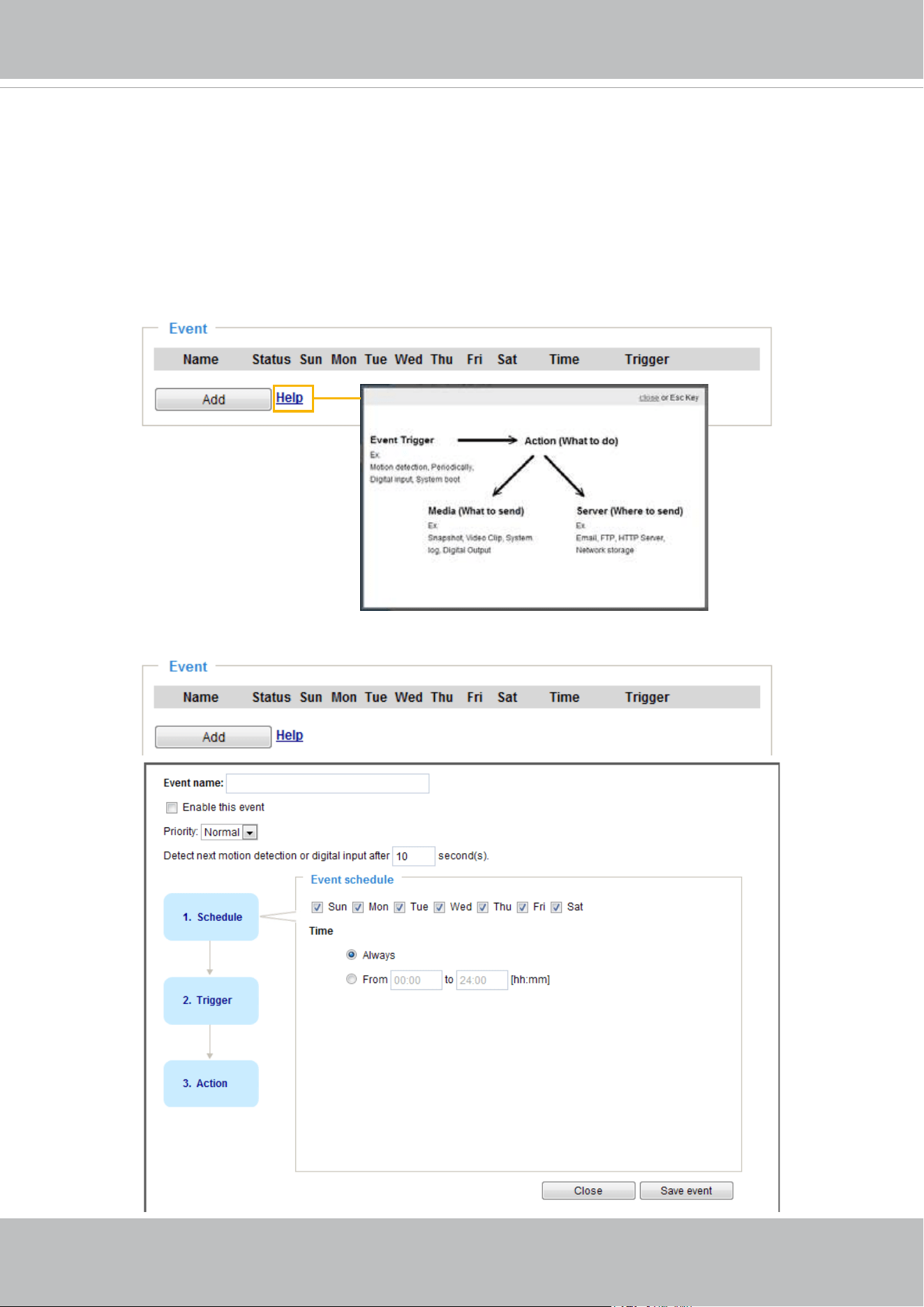
VIVOTEK
User's Manual - 123
Event > Event settings
This section explains how to congure the Network Camera to responds to particular situations
(event). A typical application is that when a motion is detected, the Network Camera sends
buffered images to an FTP server or e-mail address as notifications. Click on Help, there is
an illustration shown in the pop-up window explaining that an event can be triggered by many
sources, such as motion detection or external digital input devices. When an event is triggered,
you can specify what type of action will be performed.
Event
An event is an action initiated by a user-dened trigger source. In the Event column, click Add to open
the event settings window.
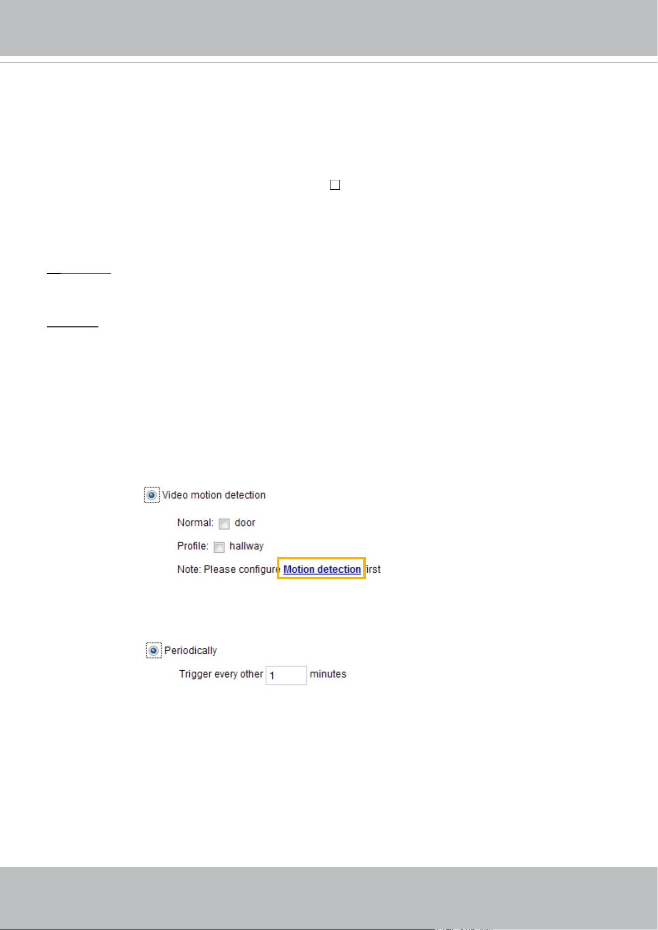
VIVOTEK
124 - User's Manual
■ Event name: Enter a name for the event setting.
■ Enable this event: Select this option to enable the current event setting.
■ Priority: Select the relative importance of this event (High, Normal, or Low). Events with a higher
priority setting will be executed rst.
■ Detect next motion detection or digital input after
seconds: Enter the duration in seconds to pause
motion detection after a motion is detected.
Follow the steps 1~3 to arrange the three elements -- Schedule, Trigger, and Action to configure an
action to take when an event is triggered. You can congure 3 event-triggered conditions.
1. Schedule
Specify the time span for the event-triggering condition. Please select the days of the week and the time
in a day (in 24-hr time format) for the recording schedule.
2. Trigger
This is the cause or stimulus which denes when to trigger the Network Camera. The trigger source can
be congured to use the Network Camera’s built-in motion detection mechanism or external digital input
devices.
There are several choices of trigger sources as shown on next page.
Select the item to display the
detailed conguration options.
■ Video motion detection
This option makes use of the built-in motion detection mechanism as a trigger source. To enable this
function, you need to congure a Motion Detection Window rst. For more information, please refer to
Motion Detection on page 138 for details.
■ Periodically
This option allows the Network Camera to trigger periodically for every other dened minute. Up to 999
minutes are allowed.
■ Digital input
This option allows the Network Camera to use an external digital input device or sensor as a trigger
source. Depending on your application, there are many choices of digital input devices on the market
which helps to detect changes in temperature, vibration, sound, and light, etc.
■ System boot
This option triggers the Network Camera when the power to the Network Camera is disconnected and
reconnected.
■ Recording notify
This option allows the Network Camera to trigger when the recording disk is full or when recording
starts to rewrite older data.
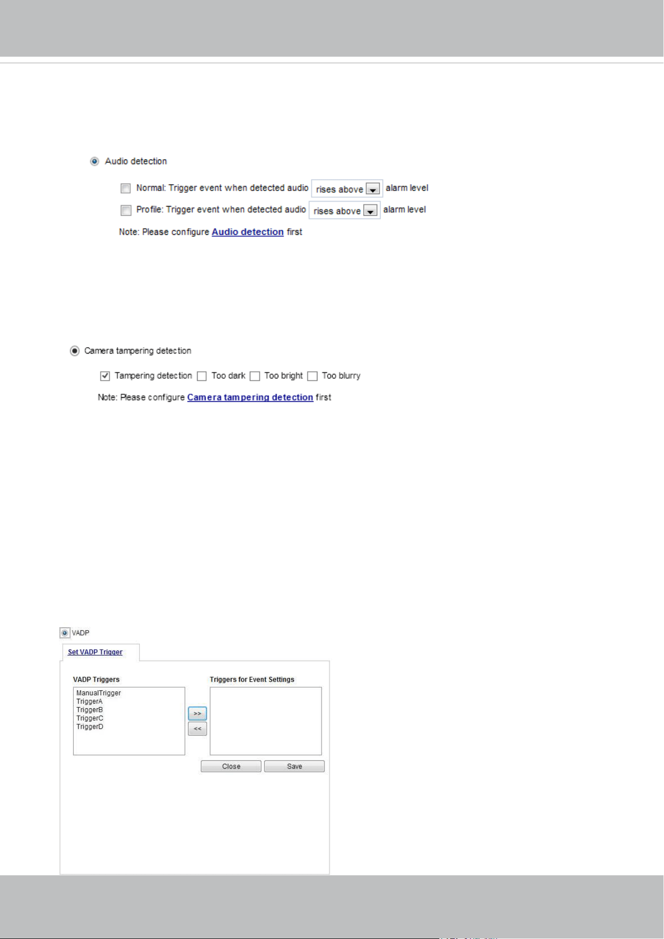
VIVOTEK
User's Manual - 125
■ Audio detection
A preset threshold can be congured with an external microphone as the trigger to system event. The
triggering condition can be an input exceeding or falling below a threshold. Audio detection can take
place as a complement to motion detection or as a method to detect activities not covered by the
camera's view. Please refer to page 141 Applications > Audio detection for more details.
Once you have a preset audio alarm level, you can dene the triggering condition either as an audio
input rises above or falls below the alarm level.
■ VADP
It is presumed that you already uploaded and enabled the VADP modules before you can associatee
VADP triggers with an Event setting.
Click on the Set VADP Trigger button to open the VADP setup menu. The triggering conditions
available with 3rd-party software modules known as VADP will be listed. Use the arrow buttons to
select these triggers. Users may implant these modules for different purposes such as triggering
motion detection, or applications related to video analysis, etc. Please refer to page 145 for the
conguration options with VADP modules.
■ Camera tampering detection
This option allows the Network Camera to trigger when the camera detects that it is being tampered
with. To enable this function, you need to congure the Tampering Detection option rst. Please refer
to page 142 for detailed information.
■ Manual triggers
An event can be manually triggered by the manual trigger buttons on the main page.
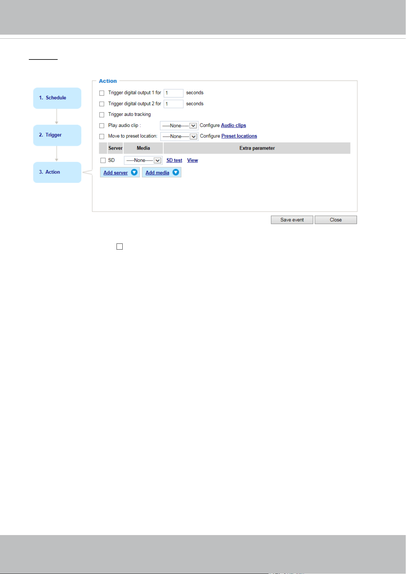
VIVOTEK
126 - User's Manual
3. Action
Dene the actions to be performed by the Network Camera when a trigger is activated.
■ Trigger digital output for
seconds
Select this option to turn on the external digital output device when a trigger is activated. Specify the
length of the trigger interval in the text box.
■ Backup media if the network is disconnected
Select this option to backup media le on SD card if the network is disconnected. Please note that this
function will only be displayed after you set up a networked storage (NAS). For more information about
how to set up network storage, please refer to page 150.
■ Trigger auto tracking
Auto tracking starts by the occurrence of another trigger.
■ Play audio clip:
A pre-loaded audio clip can be configured to be played when one triggering condition is met. For
example, when an intruder is detected, the event plays a warning message to deter an intruder.
■ Move to preset location
Select a preset location you’ve configured. Note that please configure Preset locations first. For
detailed information, please refer to page 118. Another checkbox will appear, Capture media after
moving to the location. You can select to record associated snapshot, video clip or system event
once the event is triggered and the camera moves to the preset location. See Add Media in the
following discussion.
To set an event with recorded video or snapshots, it is necessary to configure the server and media
settings so that the Network Camera will know what action to take (such as which server to send the
media les to) when a trigger is activated.
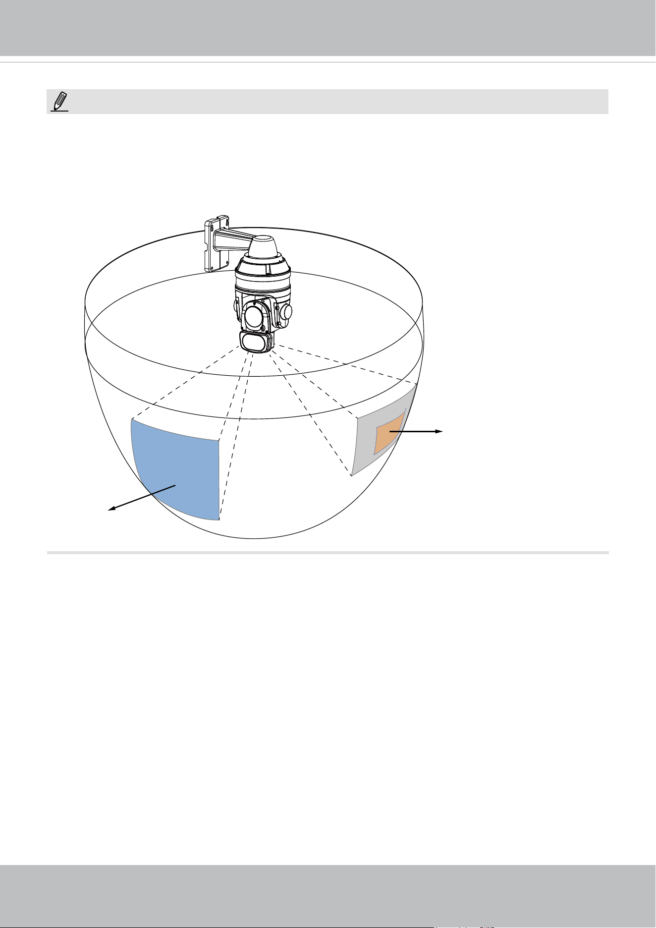
VIVOTEK
User's Manual - 127
NOTE:
Motion detection
window
Current field of view
If you congured a motion detection window as a trigger, the motion detection may become invalid when
the camera’s eld of view moved away from the detection window.
You can let camera return to the motion detection position to detect the coming event by re-conguring
your Home position in PTZ > PTZ settings (see page 114) or turn the camera to a preset position.
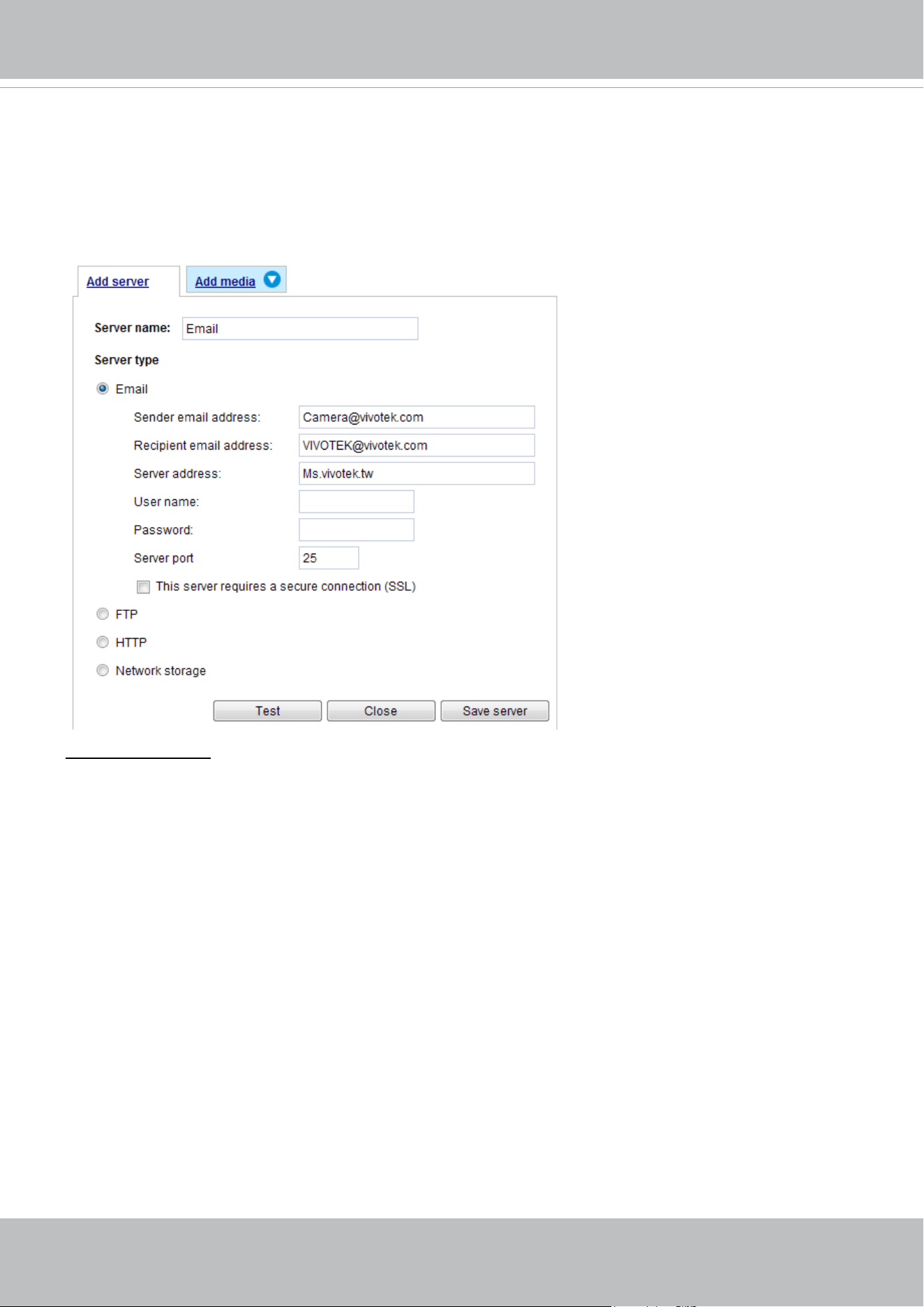
VIVOTEK
128 - User's Manual
Add server
Click Add server to unfold the server setting window. You can specify where the notication messages
are sent when a trigger is activated. A total of 5 server settings can be congured.
There are four choices of server types available: Email, FTP, HTTP, and Network storage.
Select the item
to display the detailed conguration options. You can congure either one or all of them.
Server type - Email
Select to send the media les via email when a trigger is activated.
■ Server name: Enter a name for the server setting.
■ Sender email address: Enter the email address of the sender.
■ Recipient email address: Enter the email address of the recipient.
■ Server address: Enter the domain name or IP address of the email server.
■ User name: Enter the user name of the email account if necessary.
■ Password: Enter the password of the email account if necessary.
■ Server port: The default mail server port is set to 25. You can also manually set another port.
If your SMTP server requires a secure connection (SSL), check This server requires a secure
connection (SSL).
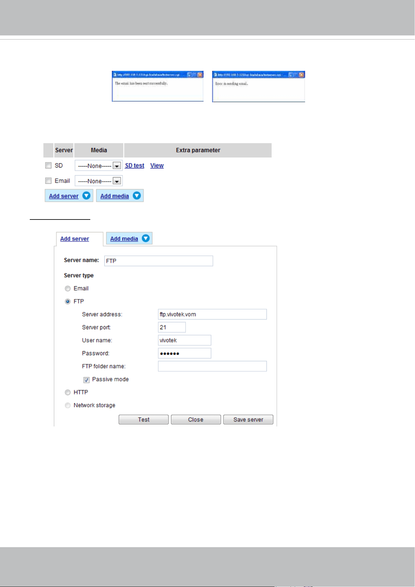
VIVOTEK
User's Manual - 129
To verify if the email settings are correctly congured, click Test. The result will be shown in a pop-up
window. If successful, you will also receive an email indicating the result.
Click Save server to enable the settings, then click Close to exit the Add server page.
After you set up the first event server, a new item for event server will automatically show up on the
Server list. If you wish to add more server options, click Add server.
Server type - FTP
Select to send the media les to an FTP server when a trigger is activated.
■ Server name: Enter a name for the server setting.
■ Server address: Enter the domain name or IP address of the FTP server.
■ Server port: By default, the FTP server port is set to 21. It can also be assigned to another port number
between 1025 and 65535.
■ User name: Enter the login name of the FTP account.
■ Password: Enter the password of the FTP account.
■ FTP folder name
Enter the folder where the media le will be placed. If the folder name does not exist, the Network
Camera will create one on the FTP server.
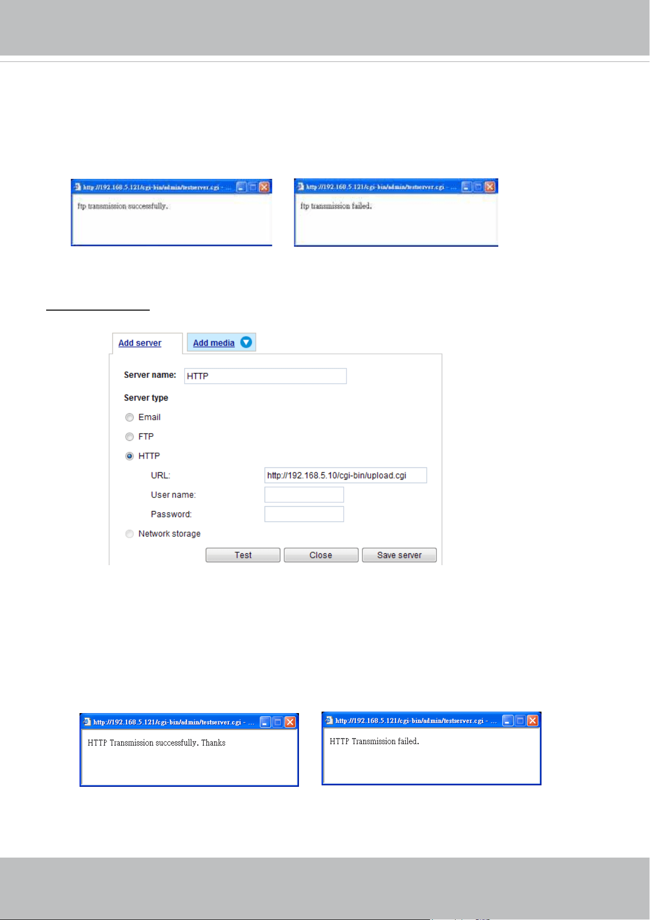
VIVOTEK
130 - User's Manual
■ Passive mode
Most firewalls do not accept new connections initiated from external requests. If the FTP server
supports passive mode, select this option to enable passive mode FTP and allow data transmission to
pass through the rewall.
To verify if the FTP settings are correctly congured, click Test. The result will be shown in a pop-up
window as shown below. If successful, you will also receive a test.txt le on the FTP server.
Click Save server to enable the settings, then click Close to exit the Add server page.
Server type - HTTP
Select to send the media les to an HTTP server when a trigger is activated.
■ Server name: Enter a name for the server setting.
■ URL: Enter the URL of the HTTP server.
■ User name: Enter the user name if necessary.
■ Password: Enter the password if necessary.
To verify if the HTTP settings are correctly congured, click Test. The result will be shown in a pop-up
window as below. If successful, you will receive a test.txt le on the HTTP server.
Click Save server to enable the settings and click Close to exit the Add server page.
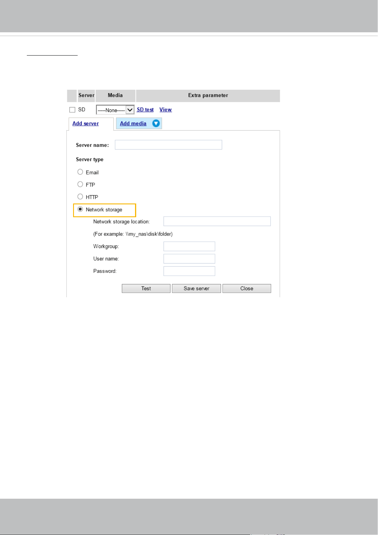
VIVOTEK
User's Manual - 131
Network storage:
Select to send the media les to a network storage location when a trigger is activated. Please refer to
NAS server on page 150 for details.
Click Save server to enable the settings, then click Close to exit the Add server page.
■ SD Test: Click to test your SD card. The system will display a message indicating success or failure. If
you want to use your SD card for local storage, please format it before use. Please refer to page 153
for detailed information.
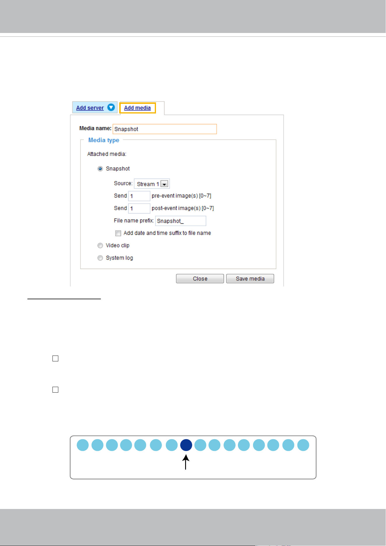
VIVOTEK
132 - User's Manual
Add media
Click
Add media
to open the media setting window. You can specify the type of media that will be sent
and preserved when a trigger is activated. A total of 5 media settings can be congured. There are three
choices of media types available: Snapshot, Video Clip, and System log.
Select the item to display the
detailed conguration options. You can congure either one or all of them.
Media type - Snapshot
Select to send snapshots when a trigger is activated.
■ Media name: Enter a name for the media setting.
■ Source: Select to take snapshots from stream 1 ~ 4. (The following options are available when the
check circle is selected.
■ Send
pre-event images
The Network Camera has a buffer area; it temporarily holds data up to a certain limit. Enter a number
to decide how many images to capture before a trigger is activated. Up to 7 images can be generated.
■ Send
post-event images
Enter a number to decide how many images to capture after a trigger is activated. Up to 7 images can
be generated.
For example, if both the Send pre-event images and Send post-event images are set to 7, a total of 15
images are generated after a trigger is activated.
■ File name prex
Enter the text that will be appended to the front of the le name.
1 pic. 2 pic. 3 pic. 4 pic. 5 pic. 6 pic. 7 pic. 8 pic. 9 pic.
10 pic. 11 pic. 10 pic. 12 pic. 13 pic. 14 pic. 15 pic.
Trigger Activation
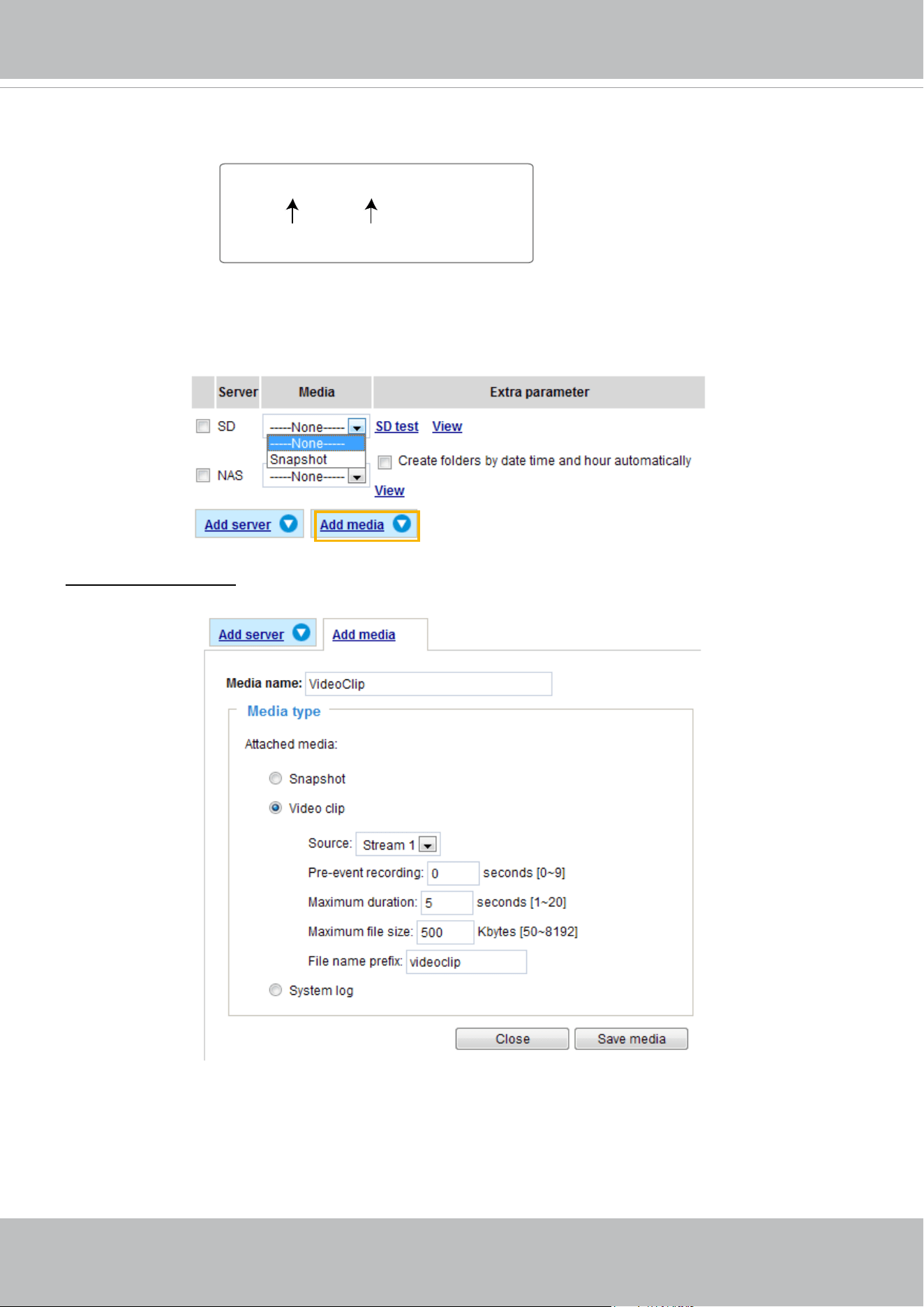
VIVOTEK
User's Manual - 133
■ Add date and time sufx to the le name
Select this option to add a date/time sufx to the le name.
For example:
Click Save media to enable the settings, then click Close to exit the Add media page.
After you set up the rst media server, a drop-down menu of existing medias will be available on the
Media list. If you wish to add more media options, click Add media again.
Media type -
Video clip
Select to send video clips when a trigger is activated.
■ Media name: Enter a name for the media setting.
■ Source: Select the source of video clip.
■ Pre-event recording
The Network Camera has a buffer area; it temporarily holds data up to a certain limit. Enter a number
to decide the duration of recording before a trigger is activated. Up to 9 seconds can be set.
Snapshot_20180320_100341
Date and time sufx
The format is: YYYYMMDD_HHMMSS
File name prex
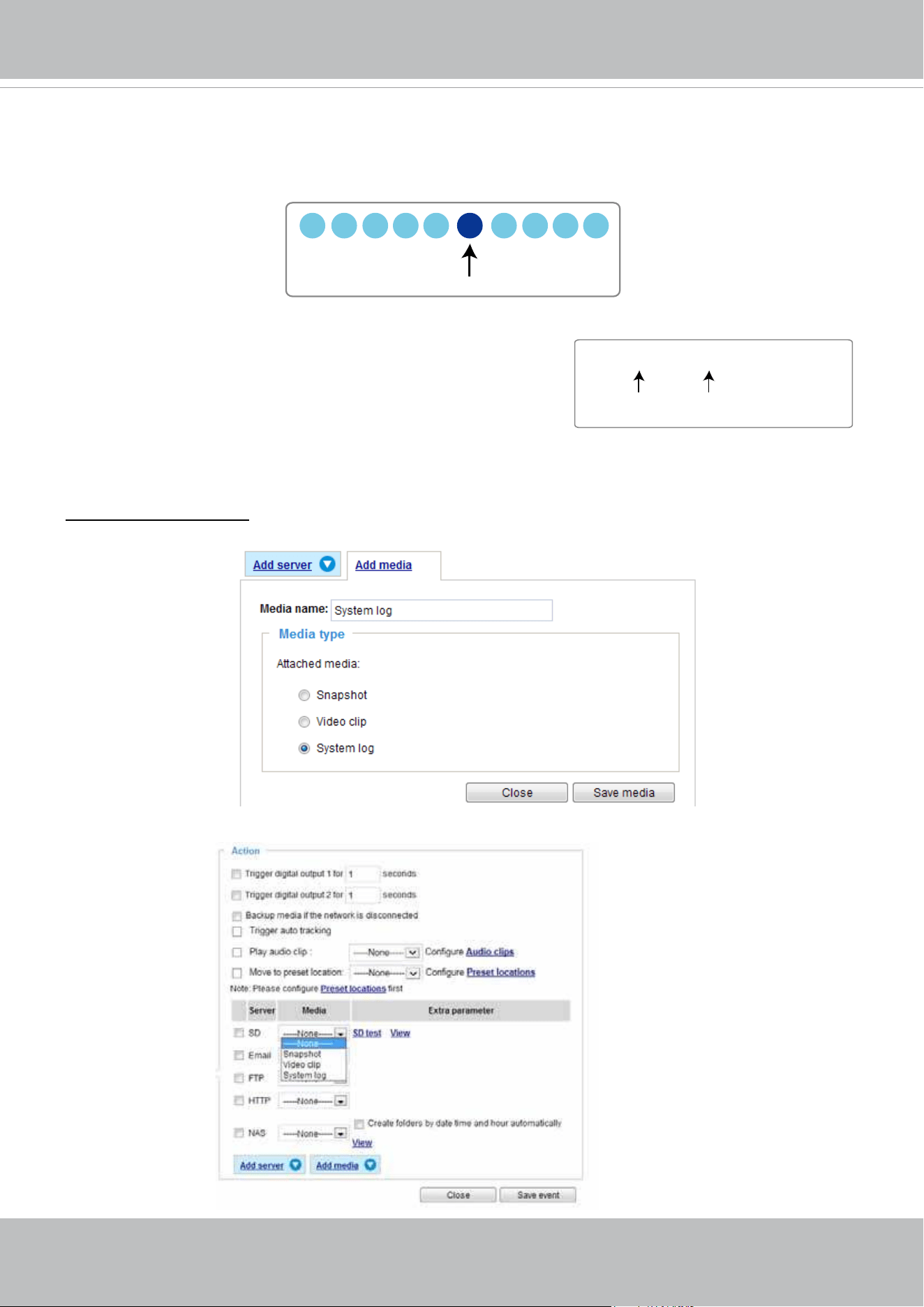
VIVOTEK
134 - User's Manual
■ Maximum duration
Specify the maximum recording duration in seconds. Up to 20 seconds can be set.
For example, if pre-event recording is set to 5 seconds and the maximum duration is set to 10
seconds, the Network Camera continues to record for another 4 seconds after a trigger is activated.
■ Maximum le size
Specify the maximum le size allowed.
■ File name prex
Enter the text that will be appended to the front of the le name.
For example:
Click Save media to enable the settings, then click Close to exit the Add media page.
Media type - System log
Select to send a system log when a trigger is activated.
Click Save media to enable the settings, then click Close to exit the Add media page.
1 sec. 2 sec. 3 sec. 4 sec. 5 sec. 6 sec. 7 sec. 8 sec. 9 sec. 10 sec.
Trigger Activation
Video_20180320_100341
Date and time sufx
The format is: YYYYMMDD_HHMMSS
File name prex
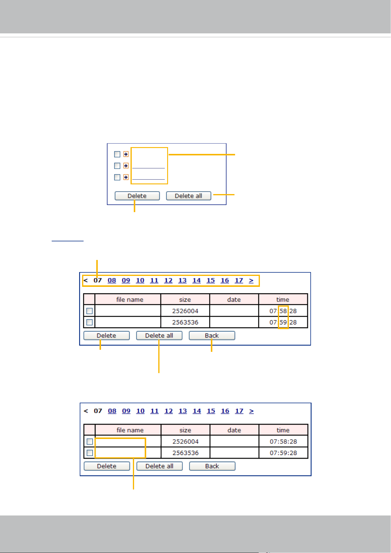
VIVOTEK
User's Manual - 135
■ View: Click this button to open a file list window. This function only apllies when an SD card and
networked storage are available.
If you click View button of SD card, a Local storage page will pop up for you to manage recorded les
on SD card. For more information about Local storage, please refer to page 153. If you click View
button of Network storage, a le directory window will pop up for you to view recorded data on Network
storage.
■ Create folders by date, time, and hour automatically: If you check this item, the system will
automatically create sub-folders named by the date.
The following is an example of a le destination with recorded video clips:
Click
20180320 to open the directory:
Video Clip_59.mp4
Video Clip_58.mp4
2018/03/20
2018/03/20
Click to delete
selected items
Click to delete all
recorded data
Click to go back to the previous
level of the directory
The format is: HH (24r)
Click to open the le list for that hour
Video Clip_59.mp4
Video Clip_58.mp4
2018/03/20
2018/03/20
The format is: File name prex + Minute (mm)
You can set up the le name prex on Add media page.
20180320
20180321
20180322
Click to delete selected items
Click to delete all recorded data
The format is: YYYYMMDD
Click to open the directory
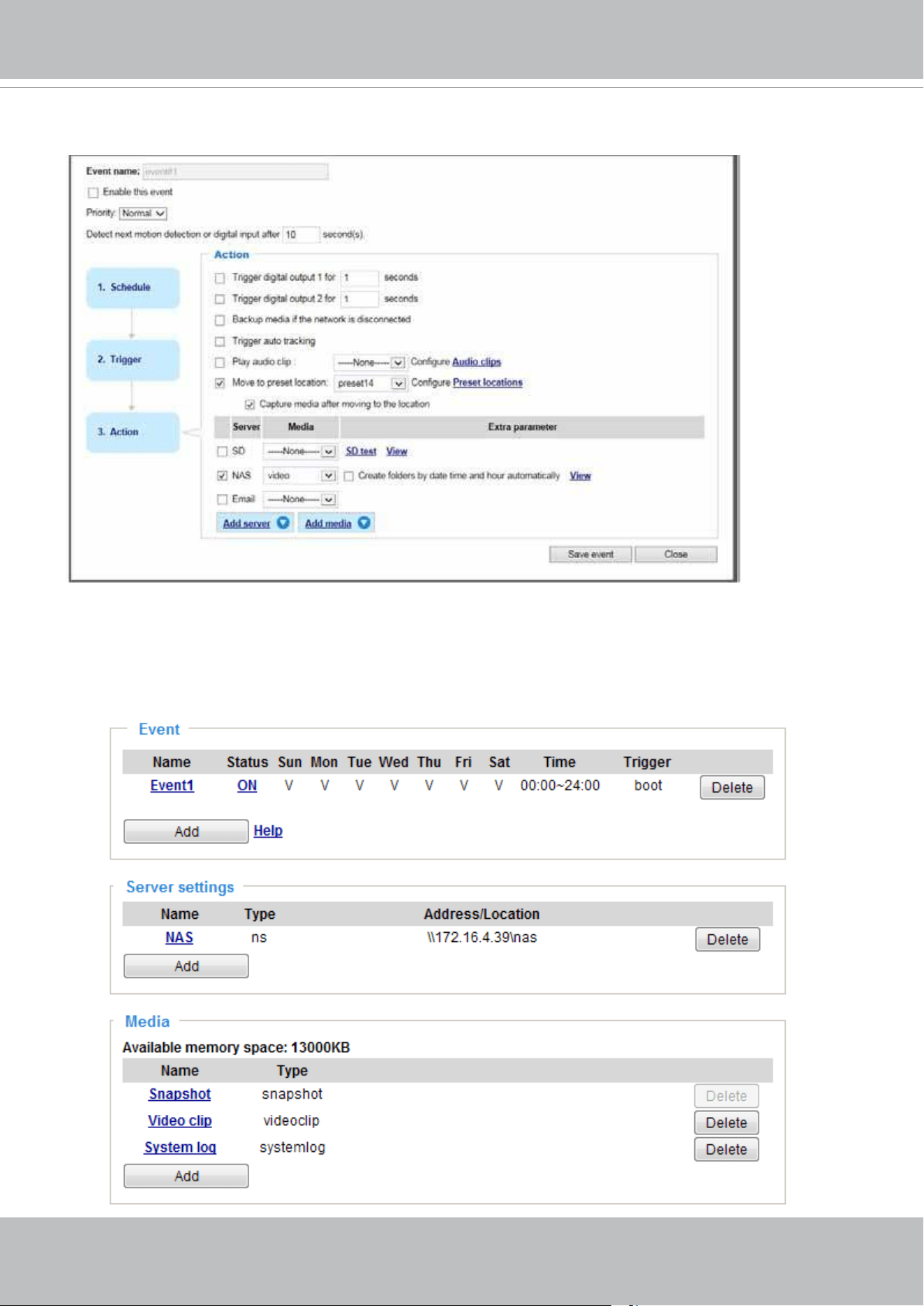
VIVOTEK
136 - User's Manual
Here is an example of the Event setting:
When completed the settings with steps 1~3 to arrange Schedule, Trigger, and Action of an event, click
Save event to enable the settings and click Close to exit the page.
The following is an example of the Event setting page:
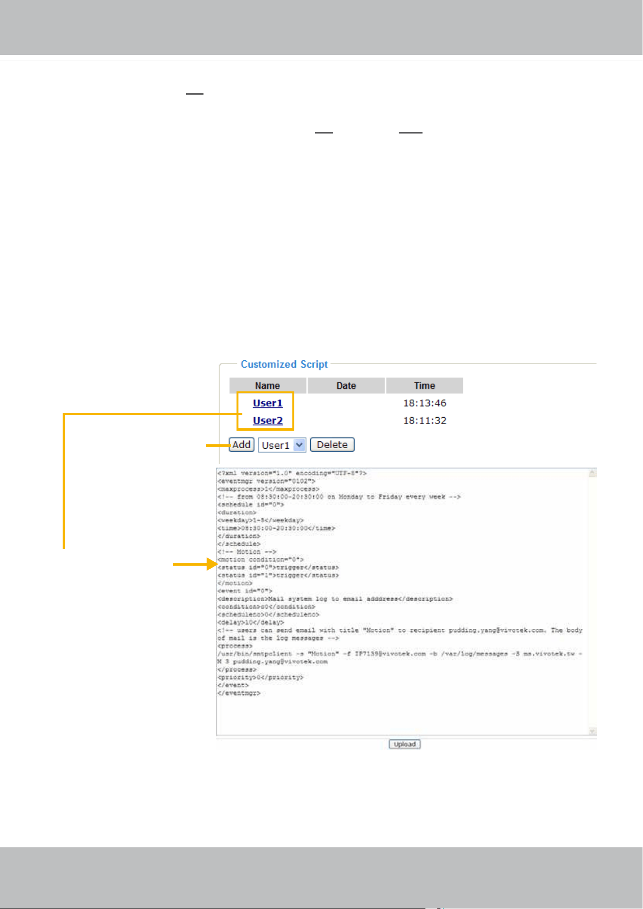
VIVOTEK
User's Manual - 137
When the Event Status is ON, once an event is triggered by motion detection, the Network Camera will
automatically send snapshots via e-mails.
If you want to stop the event trigger, you can click
ON to turn it to OFF status or click Delete to remove
the event setting.
To remove a server setting from the list, select a server name and click Delete. Note that you can only
delete a server setting when the server setting is currently not applied to an event setting.
To remove a media setting from the list, select a media name and click Delete. Note that you can only
delete a media setting when the media setting is currently not applied to an event setting.
Customized Script
This function allows you to upload a sample script (.xml le) to the camera, which will save your time on
conguring the settings. Please note that there is a limited number of customized scripts you can upload;
if the current amount of customized scripts has reached the limit, an alert message will prompt. If you
need more information, please contact VIVOTEK technical support.
2018/03/20
2018/03/20
Click to upload a le
Click to modify the
script online
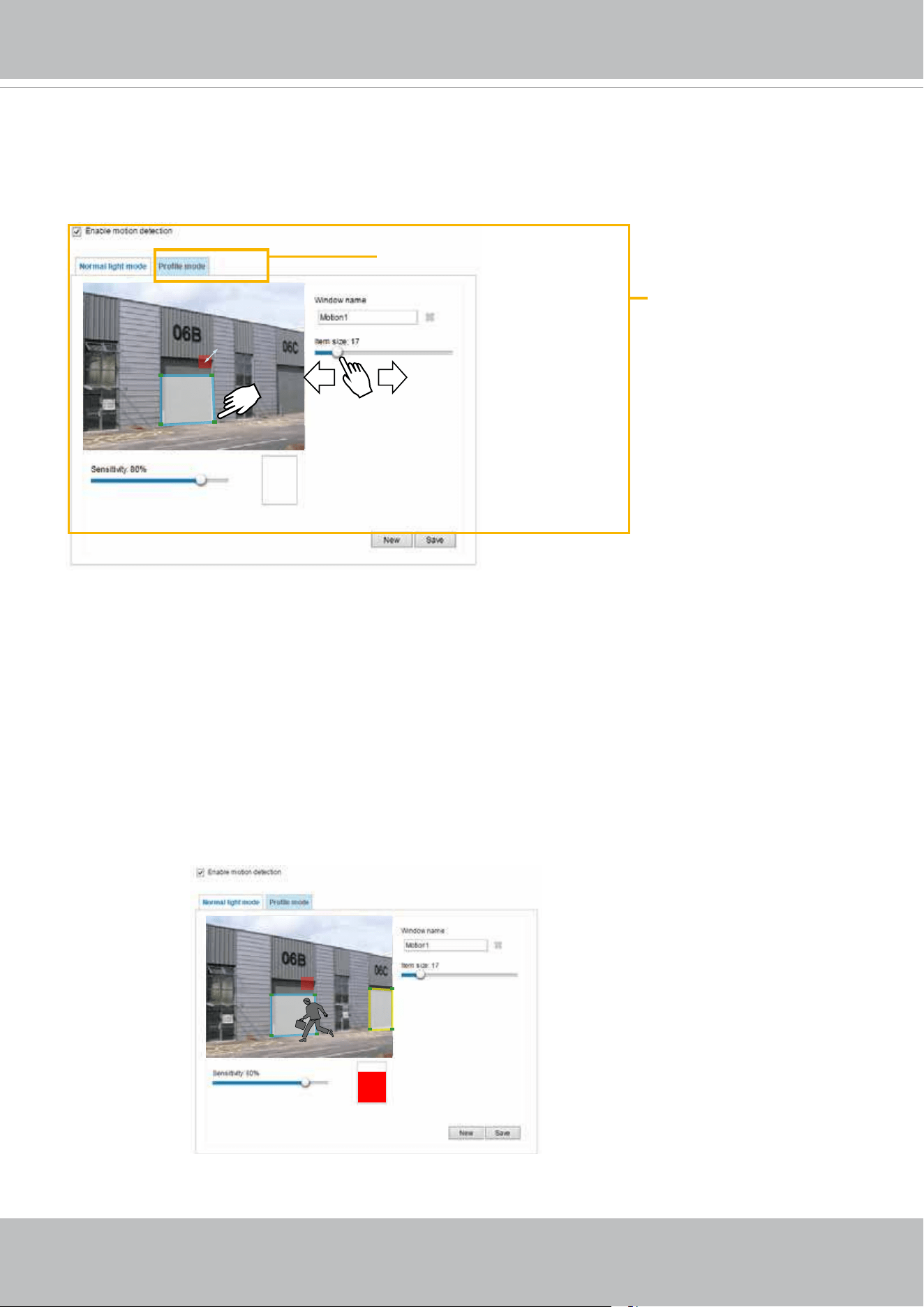
VIVOTEK
138 - User's Manual
Applications > Motion detection
This section explains how to congure the Network Camera to enable motion detection. A total
of 5 motion detection windows can be congured.
Follow the steps below to enable motion detection:
1. Click New to add a new motion detection window.
2. In the Window Name text box, enter a name for the motion detection window.
■ Use 4 mouse clicks to designate a detection window. You can change the window shape by dragging
the corner marks to a preferred location.
■ Drag the item size tab to change the minimum size of item to trigger an alarm. An item size box will
appear in the center of screen for your reference (in semi-transparent red). An intruding object must
be larger than the Item size to trigger an alarm. Change the item size according to the live view.
■ To delete a window, click the X mark on the right of the window name.
3. Dene the sensitivity to moving objects by moving the Sensitivity slide bar. Note that a high sensitivity
is prone to produce false alarms such as the fast changes of light (such as day/night mode switch,
turning lights on/off). A movement must persist longer than 0.3 second for the motion to be detected.
4. Click Save to enable the settings.
5. Select Enable motion detection to enable this function.
For example:
The Percentage Indicator will rise or fall depending on the variation between sequential images. When
motions are detected by the Network Camera and are considered to exceed the preset threshold, the red
bar rises. Meanwhile, the motion detection window will be outlined in red.
Motion Detection Setting 2:
For special situations
Motion Detection Setting 1:
For normal situations
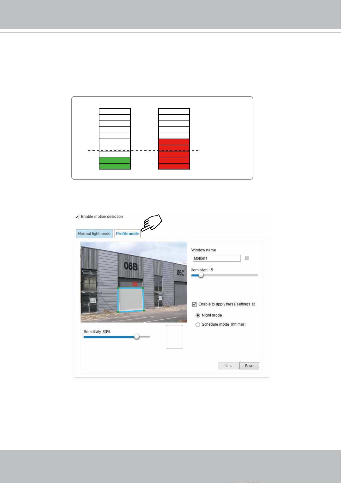
VIVOTEK
User's Manual - 139
A green bar indicates that even though motions have been detected, the event has not been triggered
because the image variations still fall under the preset threshold.
If you want to congure other motion detection settings for day/night/schedule mode (e.g., for a different
lighting condition), please click Profile to open the Motion Detection Profile Settings page as shown
below. Another three motion detection windows can be congured on this page.
Larger than the
min. item size
Photos or videos can be captured instantly and congured to be sent to a remote server (via an Email or
FTP server). For more information on how to congure an event setting, please refer to Event settings on
page 123.
Please follow the steps beolw to set up a prole:
1. Create a new motion detection window.
2. Click the Prole mode tab.
3. Select the applicable Schedule mode. Please manually enter a time range.
4. Click Save to enable the settings and click Close to exit the page.
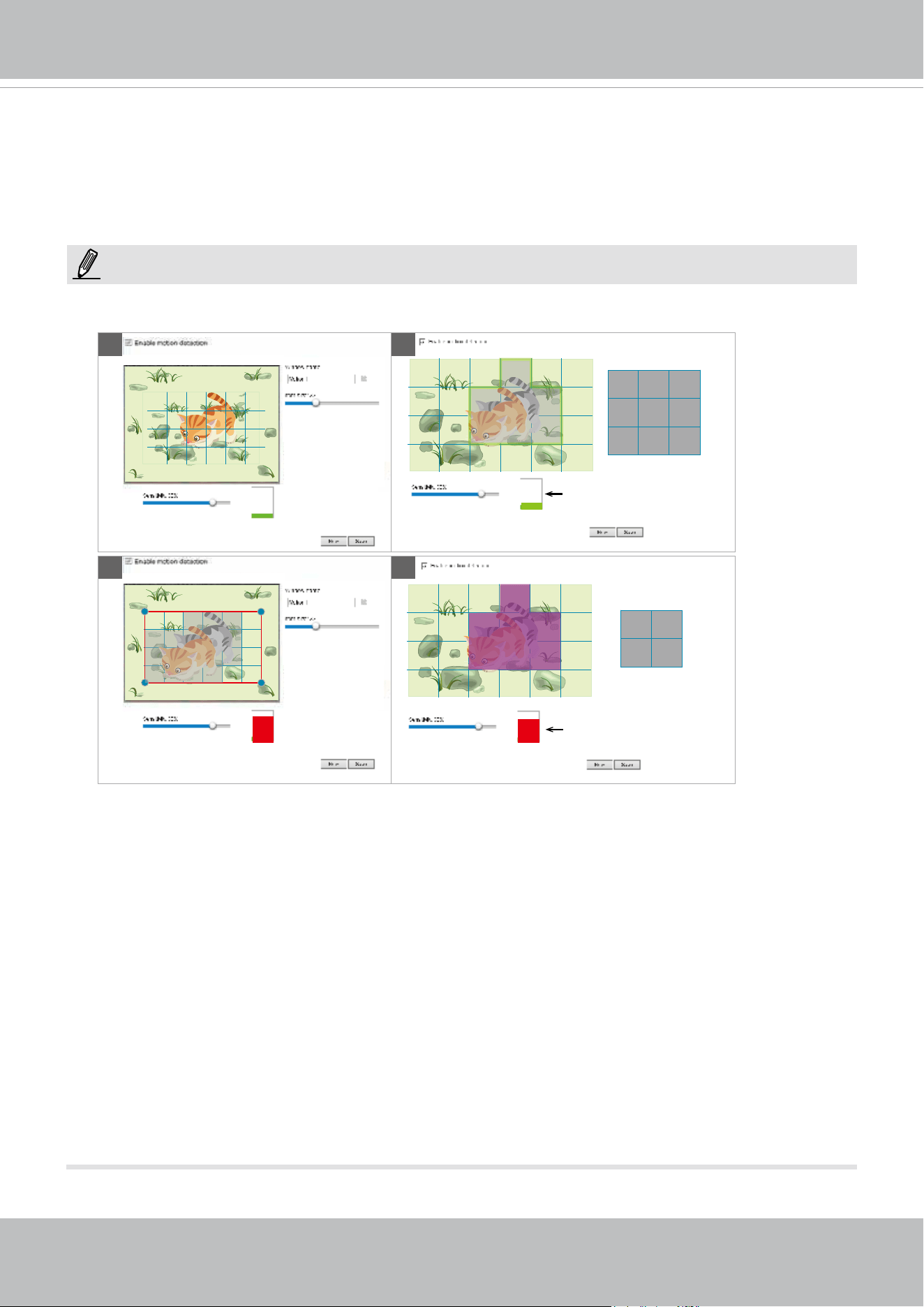
VIVOTEK
140 - User's Manual
This motion detection window will also be displayed on the Event Settings page. You can go to Event
> Event settings > Trigger to select it as a trigger source. Please refer to page 124 for detailed
information.
► How does motion detection work?
There are two motion detection parameters: Sensitivity and Min. Item Size. As illustrated above, frame
A and frame B are two sequential images. Pixel differences between the two frames are detected and
highlighted in gray in which the sensitivity setting will take effect. Sensitivity is a value that expresses
the sensitivity to moving objects. A higher sensitivity setting allows camera to detect slight movements
while a lower sensitivity setting will neglect them.
The minimum item size is a threshold value that determines how many “alerted pixels” can trigger an
event. When the size of an intruding object is larger than the minimum size, and its movement persist
for 0.3 second, the motion is judged to exceed the dened threshold; and the motion window will be
outlined in red. With a large minimum item size, the size of moving object in frame C is considered as
smaller than the minimum item size, no motion alarm is triggered. With a smaller minimum item size,
the same moving object in frame D triggers the alarm.
For applications that require a high level of security management, it is suggested to use higher
sensitivity settings. However, a higher sensitivity level can also produce false alarms due to fast light
changes when switching between the day and night modes, AE switch, turning the light on or off, etc.
A
B D
C
Min. item size
Alerted pixels < Min. item size
Alerted pixels > Min. item size
Min. item size
NOTE:
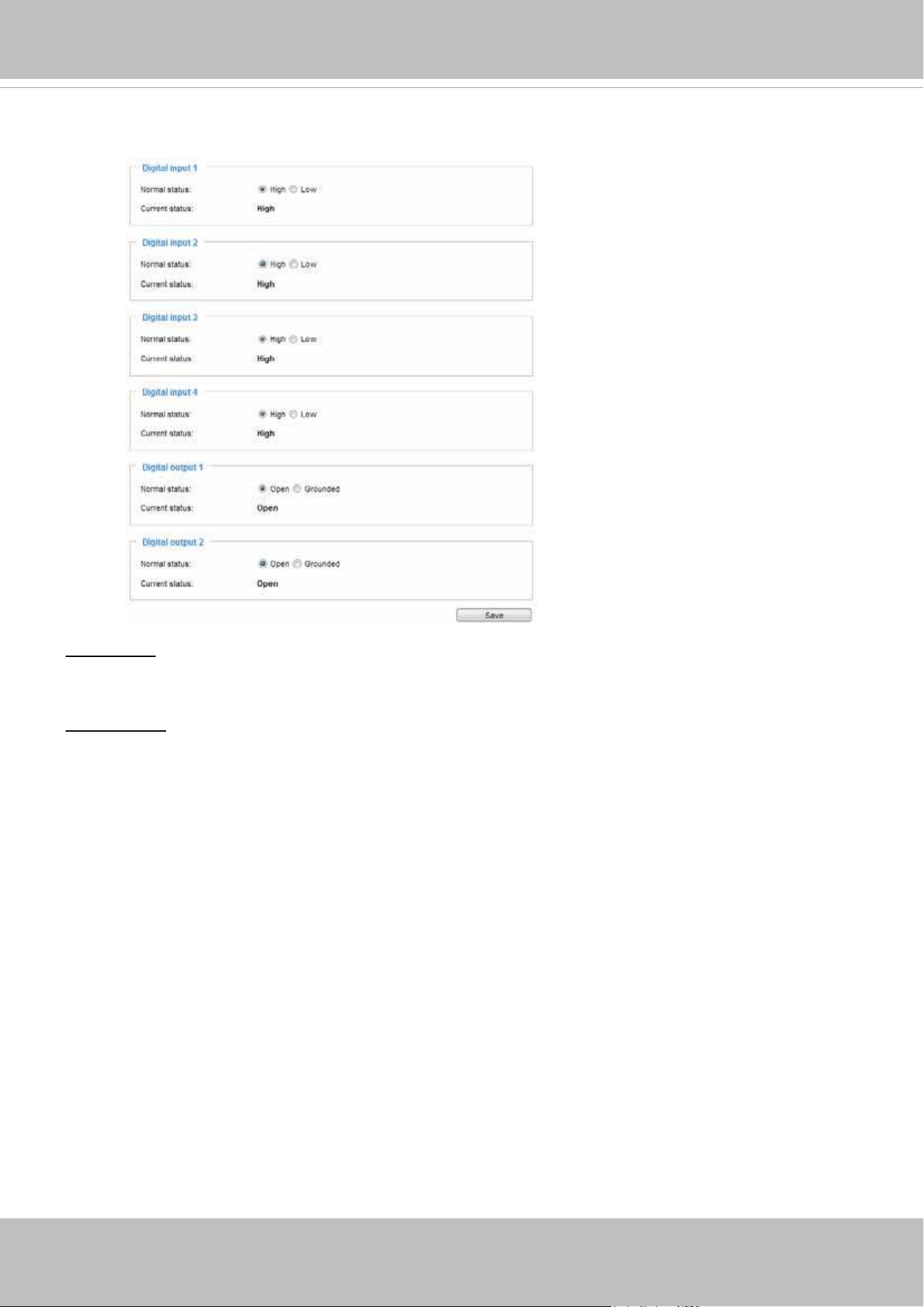
VIVOTEK
User's Manual - 141
Applications > DI and DO
Digital input: Select High or Low to dene normal status for the digital input. Connect a digital input from
a sensor device to the camera, the Network Camera will report the current signal status. You may then
congure the Normal status (non-trigger status) as High or Low.
Digital output: Select High or Low to dene normal status for the digital output. Connect an output line to
an external device, the Network Camera will report the current signal status. You may then congure the
Normal status (non-trigger status) as High or Low.
Set up the event source as DI on Event > Event settings > Trigger. Please refer to page 124 for
detailed information.
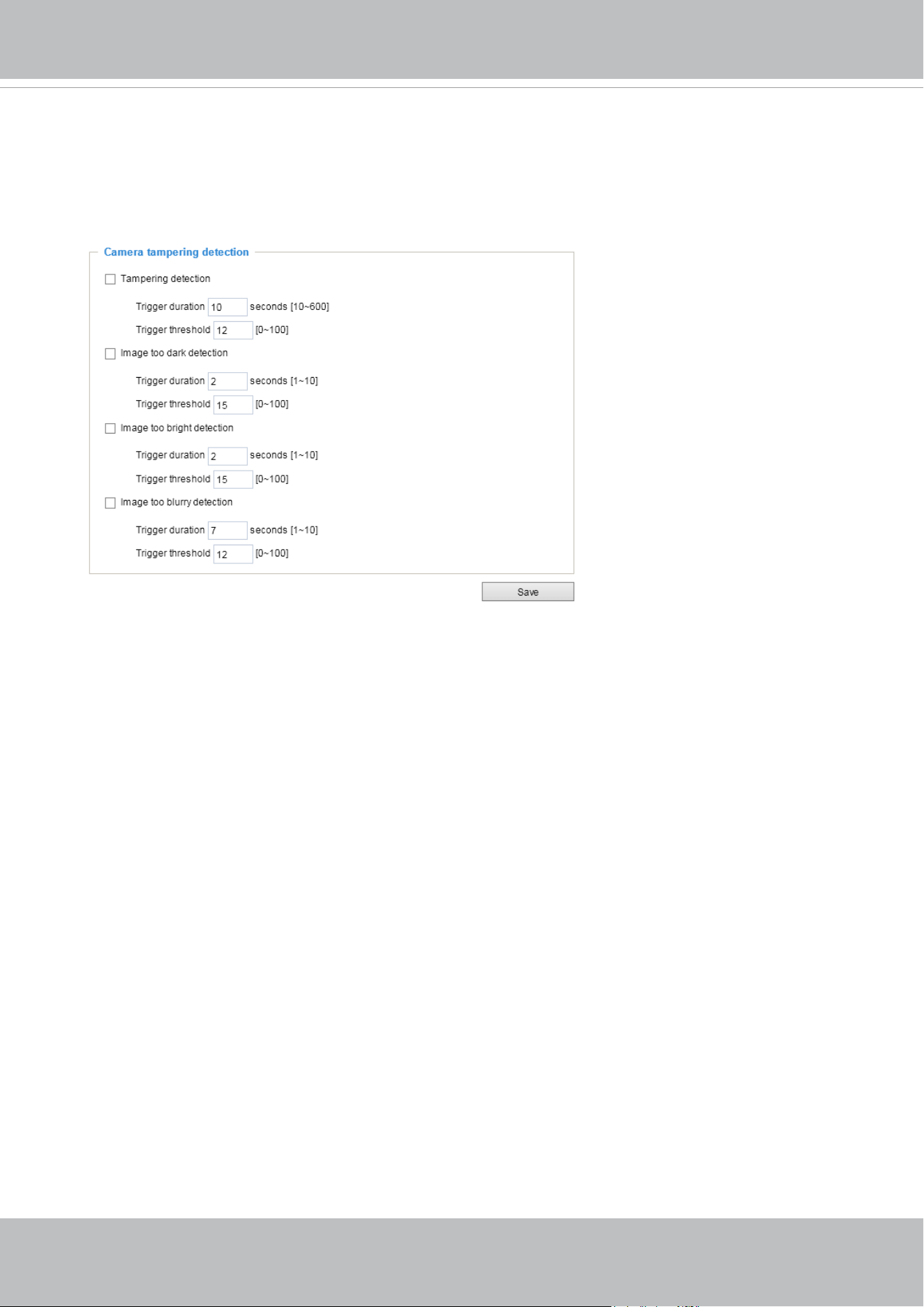
VIVOTEK
142 - User's Manual
Applications > Tampering detection
This section explains how to set up camera tamper detection. With tamper detection, the
camera is capable of detecting incidents such as redirection, blocking or defocusing, or even
spray paint.
Please follow the steps below to set up the camera tamper detection function:
1. Click to select the checkbox before tampering conditions: Tampering detection, Image too
dark, Image too bright, and Image too blurry. Enter the tamper trigger duration. (10 sec. ~
10 min.) The tamper alarm will be triggered only when the tampering factor (the difference
between current frame and pre-saved background) exceeds the trigger threshold. Conditions
such as image too dark, too bright, or too blurry (defocused) can also be configured as
tampering conditions. The Trigger threshold determines how sensitive your is tamper
detection setting.
Too bright: shining a flash light. The average lighting level of the scene is taken into
consideration.
Too dark: covering the objective or spraying paint.
Too blurry: blurry scene can be the result of strong interference on the device, such as EMI
interference.
2. You can configure Tampering Detection as a trigger element to the proactive event
configurations in Event -> Event settings -> Trigger. For example, when the camera is
tampered with, camera can be congured to send the pre- and post-event video clips to a
networked storage device. Please refer to page 150 for detailed information.
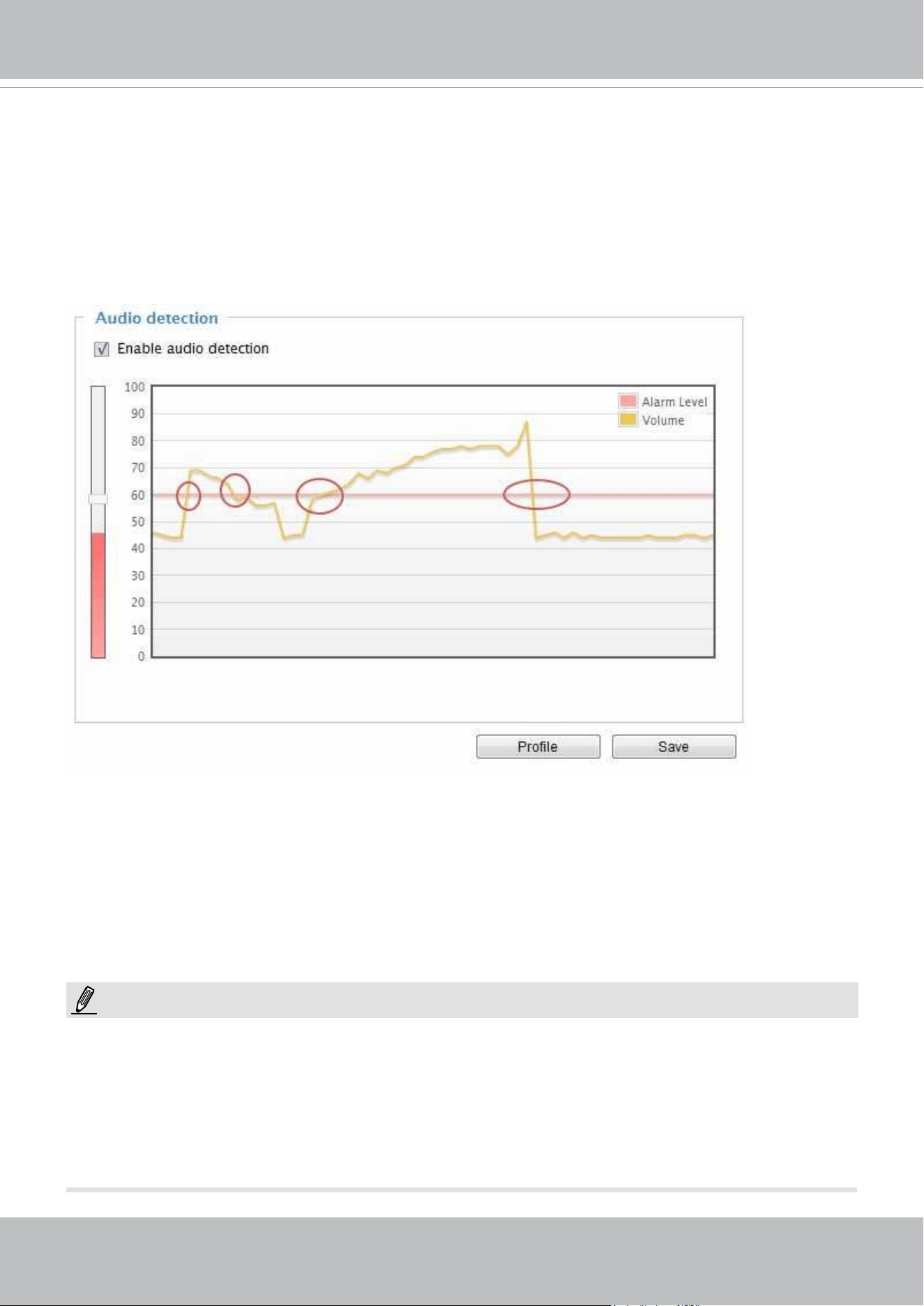
VIVOTEK
User's Manual - 143
Applications > Audio detection
Audio detection, along with video motion detection, is applicable in the following scenarios:
1. Detection of activities not covered by camera view, e.g., a loud input by gun shots or breaking a door/
window.
2. A usually noisy environment, such as a factory, suddenly becomes quiet due to a breakdown of
machines.
3. A PTZ camera can be directed to turn to a preset point by the occurrence of audio events.
4. Dark environments where video motion detection may not function well.
The red circles indicate where the audio alarms can be triggered when breaching or falling below the
preset threshold.
How to congure Audio detection:
1. Once the Audio detection window is opened, the current sound input will be interactively indicated
by a uctuating yellow wave diagram.
2. Use a mouse click to drag the Alarm level tab to a preferred location on the slide bar.
3. Select the “Enable audio detection“ checkbox and click Save to enable the feature.
1. Note that the volume numbers (0~100) on the side of wave diagram does not represent decibel (dB).
Sound intensity level has already been mapped to preset values. You can, however, use the real-
world inputs at your installation site that are shown on the wave diagram to congure an alarm level.
2. To configure this feature, you must not mute the audio in Configuration > Media > Audio.
The default of the camera can be muted due to the lack of an internal microphone. An external
microphone is provided by users.
NOTE:
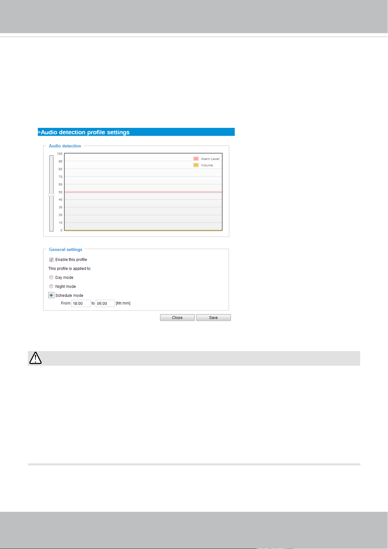
VIVOTEK
144 - User's Manual
IMPORTANT:
• If the Alarm level and the received volume are set within a range of 20% on the wave
diagram, frequent alarms will be triggered. It is recommended to set the Alarm level farther
apart from the detected sound level.
• To configure and enable this feature, you must not configure video stream #1 into motion
JPEG. If an external microphone input is connected and recording of audio stream is
preferred, audio stream is transmitted between camera and viewer/recording station along
with stream #1.
• Refer to page 78 for Audio settings, and page 72 for video streaming settings.
You can use the Prole window to congure a different Audio detection setting. For example, a place can
be noisy in the day time and become very quiet in the night.
1. Click on the Enable this prole checkbox. Once the Audio detection window is opened, the current
sound input will be interactively indicated by a uctuating yellow wave diagram.
2. Use a mouse click to drag the Alarm level tab to a preferred location on the slide bar.
3. Select the Day, Night, or Schedule mode check circles. You may also manually congure a period
of time during which this prole will take effect.
4. Click Save and then click Close to complete your conguration.
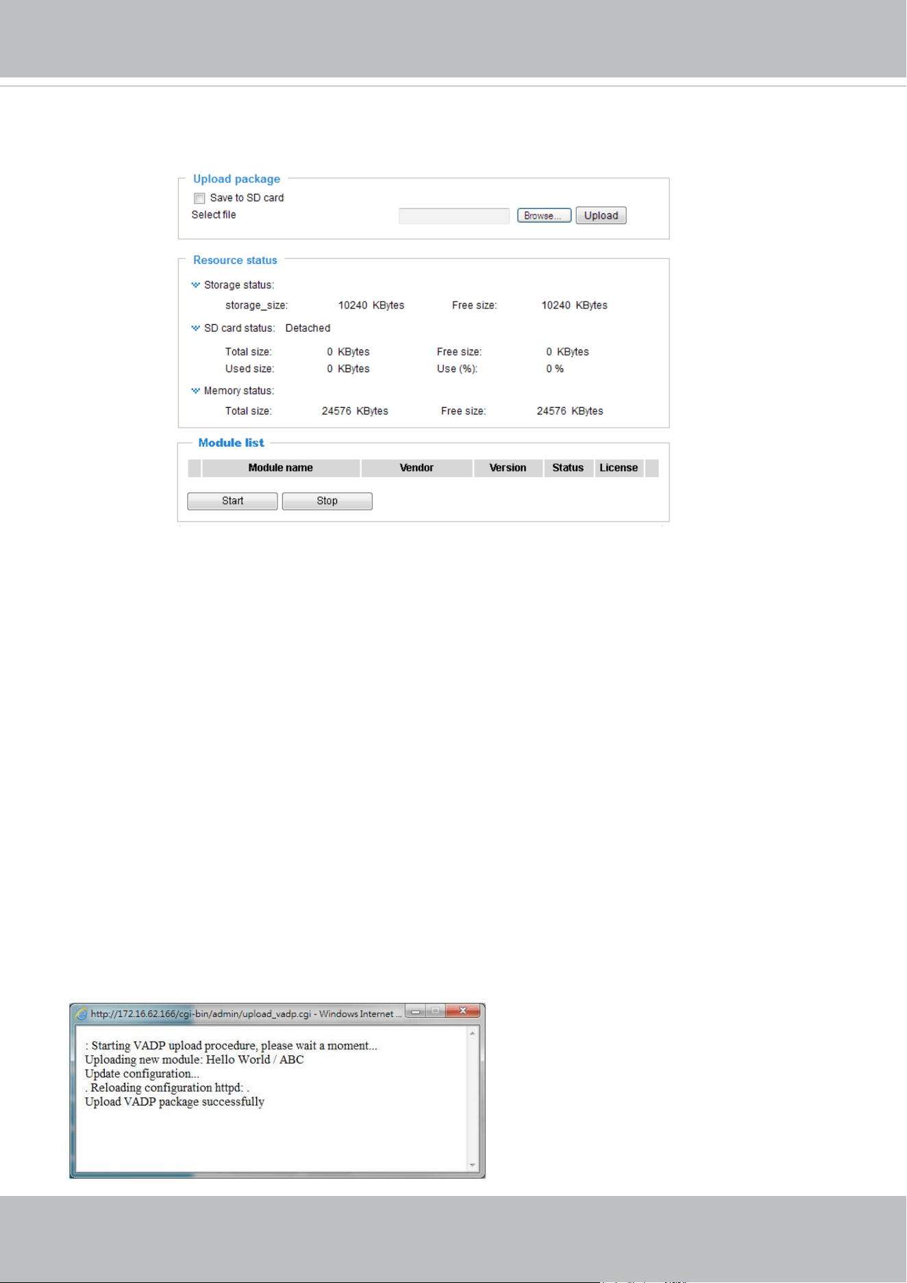
VIVOTEK
User's Manual - 145
Applications > VADP (VIVOTEK Application Development Platform)
Users can store and execute VIVOTEK's or 3rd-party software modules onto the camera's
flash memory or SD card. These software modules can apply in video analysis for intelligent
video applications such as license plate recognition, object counting, or as an agent for edge
recording, etc.
• Once the software package is successfully uploaded, the module conguration (vadp.xml)
information is displayed. When uploading a module, the camera will examine whether the
module fits the predefined VADP requirements. Please contact technical support or the
vendor of your 3rd-party module for the parameters contained within.
• Users can also run VIVOTEK's VADP packages as a means to access updated functionality
instead of replacing the entire rmware.
• Note that for some cameras the ash is too small to hold VADP packages. These cameras
will have its "Save to SD card" checkbox selected and grayed-out for all time.
• The le system of SD card (FAT32) does not support soft (symbolic) link. It will return failure
if your module tries to create soft links on SD card.
To utilize a software module, acquire the software package and click Browse and Upload
buttons. The screen message for a successful upload is shown below:
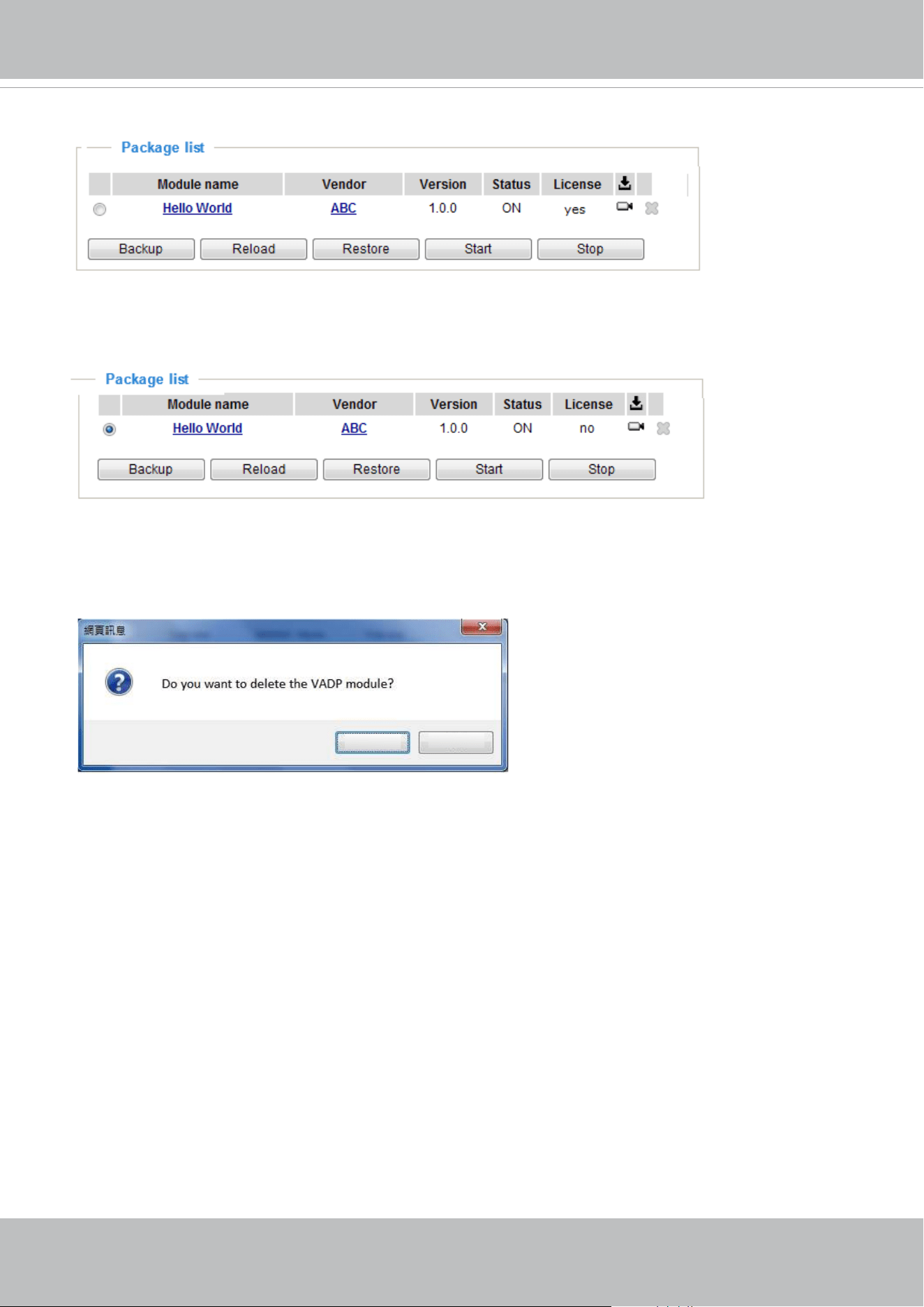
VIVOTEK
146 - User's Manual
To start a module, select the checkcircle in front, and click the Start button.
If you should need to remove a module, select the checkcircle in front and then click the Stop
button. By then the module status will become OFF, and the X button will appear at the end of
the row. Click on the X button to remove an existing module.
When prompted by a conrm message, Click Yes to proceed.
Ye s
No
Note that the actual memory consumed while operating the module will be indicated on the
Memory status eld. This helps determine whether a running module has consumed too much
of system resources.
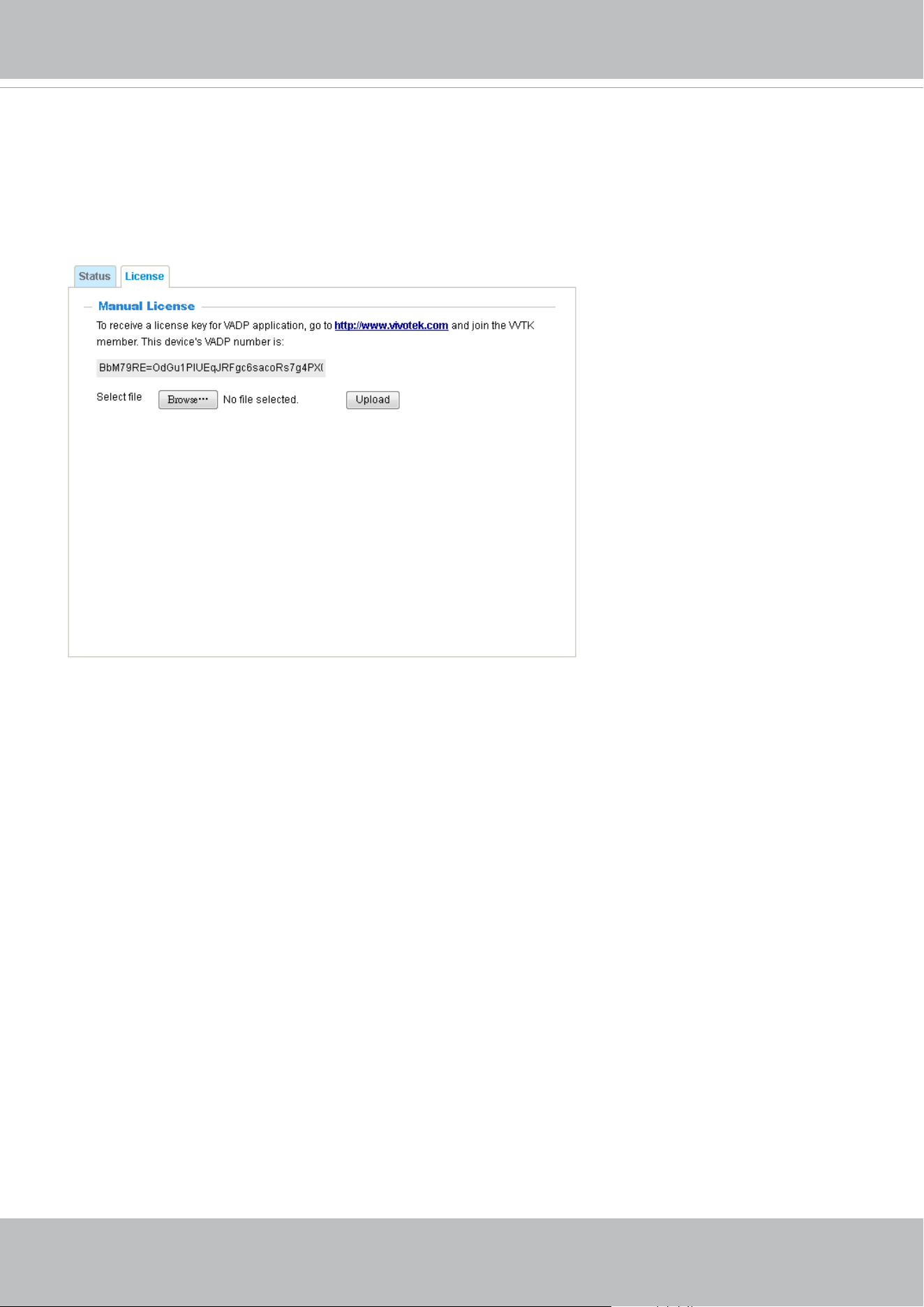
VIVOTEK
User's Manual - 147
On the License page, register and activate the license for using VIVOTEK's VADP modules. You
should acquire the license key elsewhere, and manually upload to the network camera.
Follow the onscreen instruction on VIVOTEK's website for the registration procedure.
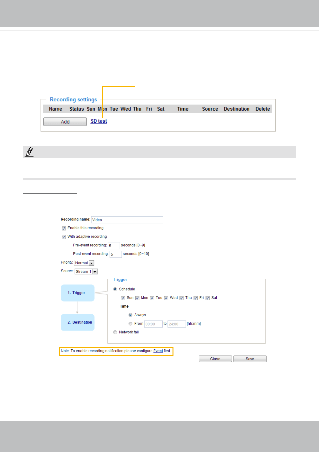
VIVOTEK
148 - User's Manual
Recording > Recording settings
This section explains how to congure the recording settings for the Network Camera.
Recording Settings
► Please remember to format your SD card when using it for the rst time. Please refer to page 153 for
detailed information.
Recording Settings
Click Add to open the recording setting window. On this page, you can dene the adaptive recording,
recording source, recording schedule, and recording capacity. A total of 2 recording settings can be
congured.
■ Recording name: Enter a name for the recording setting.
■ Enable this recording: Select this option to enable video recording.
■ With adaptive recording:
Select this option will activate the frame rate control according to alarm trigger. The frame control
means that when there is alarm trigger, the frame rate will raise up to the value you’ve set on Stream
setting page. Please refer to page 73 for more information.
Insert your SD card and click here to test
NOTE:
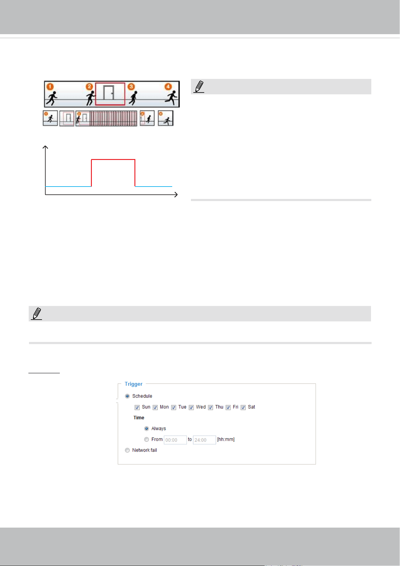
VIVOTEK
User's Manual - 149
If you enable adaptive recording and enable time-shift cache stream on Camera A, only when an event
is triggered on Camera A will the server record video streams in the full frame rate; otherwise, it will only
request the I frame data during normal monitoring, thus effectively save lots of bandwidth and storage.
The alarm trigger includes: motion detection and DI detection. Please refer to Event settings on page 123.
■ Pre-event recording and post-event recording
The Network Camera has a buffer area; it temporarily holds data for up to a certain limit. Enter a
number to decide the duration of recording that will take place before and after a trigger is activated.
■ Priority: Select the relative importance of this recording (High, Normal, or Low). Recording with a higher
priority setting will be executed rst.
■ Source: Select a stream as the recording source.
► To enable recording notication, please congure Event settings rst. Please refer to page 123.
Please follow steps 1~2 below to set up the recording:
1. Trigger
Select a trigger source.
■ Schedule: The server will start to record les on the local storage or to a networked storage device
(NAS).
■ Network fail: Since the time when the network fails, the server will start to record files on the local
storage (SD card).
Time
Bandwidth
Bandwidth
Activity Adaptive Streaming
for Dynamic Frame Rate Control
I frame ---> Full frame rate ---> I frame
Continuous recording
► To enable adaptive recording, please make sure
you’ve set up the trigger source such as Motion
Detection, DI Device, or Manual Trigger.
► When there is no alarm trigger:
- JPEG mode: record 1 frame per second.
- H.265 or H.264 mode: record I frame only.
► When the I frame period is >1s on Video settings
page, it should be forced to make the I frame period
to 1s when adaptive recording is activated.
NOTE:
NOTE:
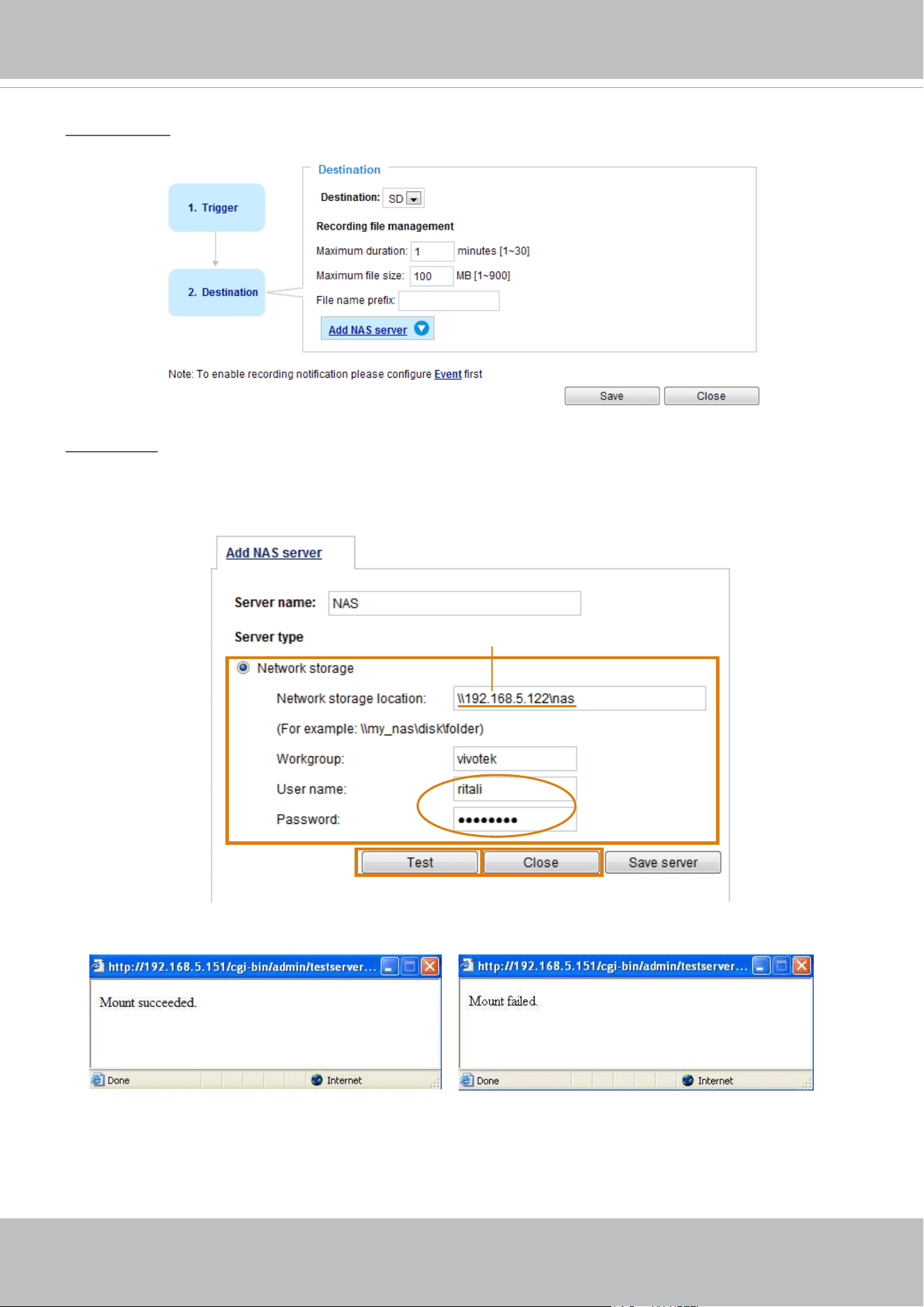
VIVOTEK
150 - User's Manual
2. Destination
You can select the SD card or network attached storage (NAS) for recording video les.
NAS server
Click Add NAS server
to open the server setting window and follow the steps below to set up:
1. Fill in the information for your server.
For example:
2. Click Test to check the setting. The result will be shown in the pop-up window.
1
2 4
Network storage path
(\\server name or IP address\folder name)
User name and
password for your
server
3
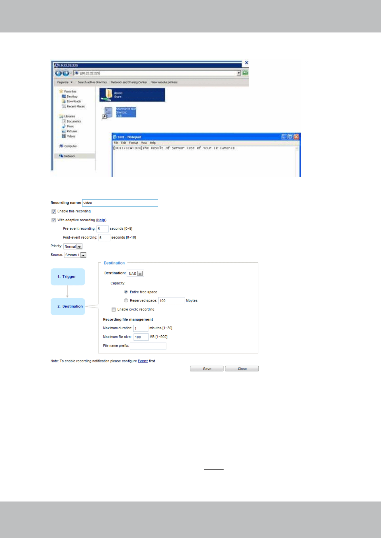
VIVOTEK
User's Manual - 151
If successful, you will receive a test.txt le on the network storage server.
3. Enter a server name.
4. Click Save to complete the settings and click Close to exit the page.
■ Capacity: You can select either the entire storage space available or specify a reserved space. The
recording size limit must be larger than the reserved space for cyclic recording. The reserved space
is used during cyclic recording to prevent malfunctions that might occur during the transaction stage
when the video feeds are about to ll up the storage space, and new data is still coming. This value
must be larger than 15 MBytes.
■ Enable cyclic recording: If you check this item, when the maximum capacity is reached, the oldest les
will be overwritten by the latest ones.
■ File name prex: Enter the text that will be appended to the front of the le name.
If you want to enable recording notication, please click
Event
to set up. Please refer to Event > Event
settings on page 123 for more details.
When completed, select Enable this recording. Click Save to enable the setting and click Close to exit
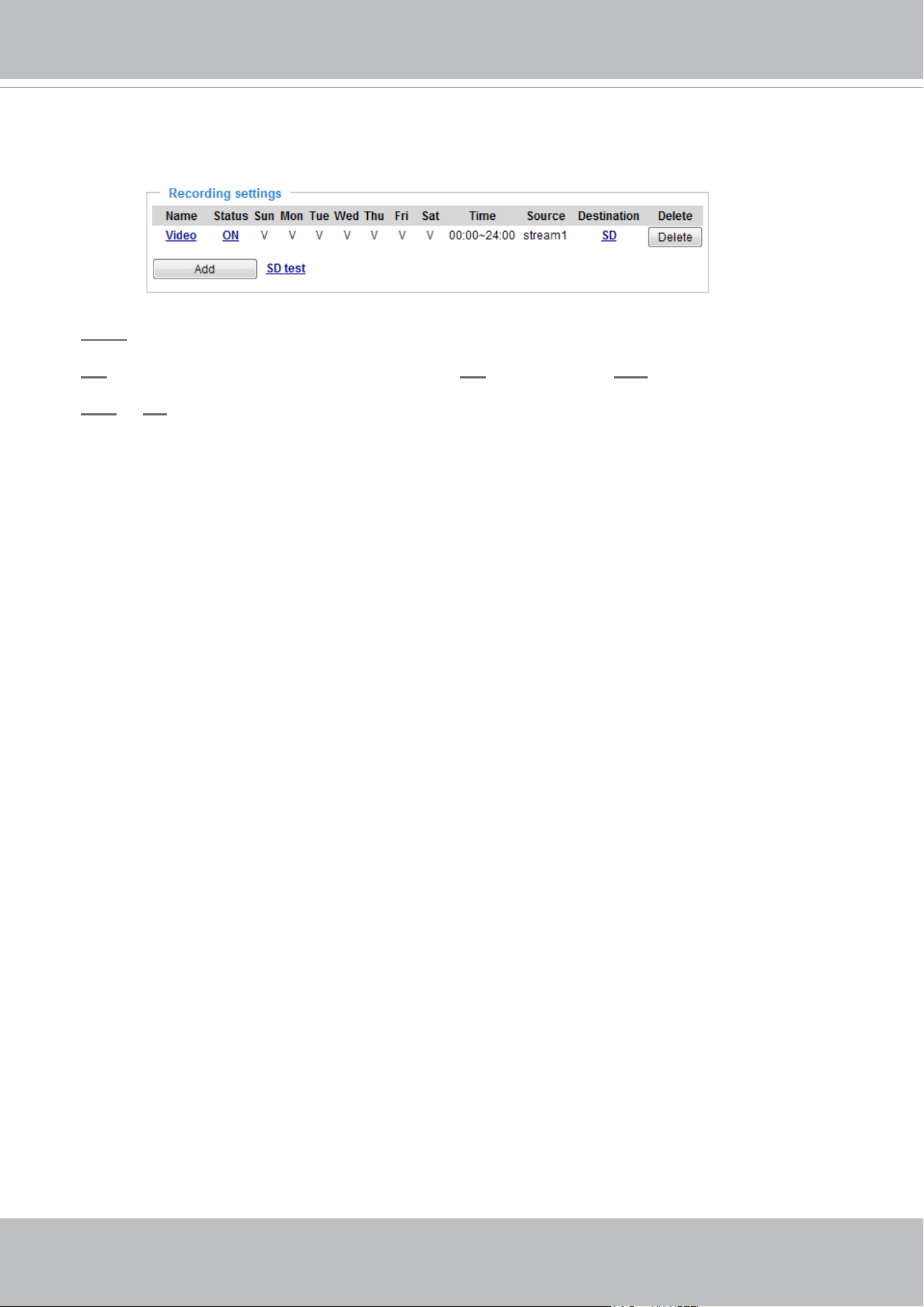
VIVOTEK
152 - User's Manual
this page. When the system begins recording, it will send the recorded les to a networked storage or SD
card. The new recording name will appear on the recording page as shown below.
To remove a recording setting from the list, select it and click Delete.
■
Video (Name): Click to open the Recording settings page to modify its details.
■ ON (Status): Click to manually adjust the Status. (ON: start recording; OFF: stop recording)
■
NAS or SD (Destination): Click to open the le list of recordings as shown below. For more information
about folder naming rules, please refer to page 135 or page 119 for details.
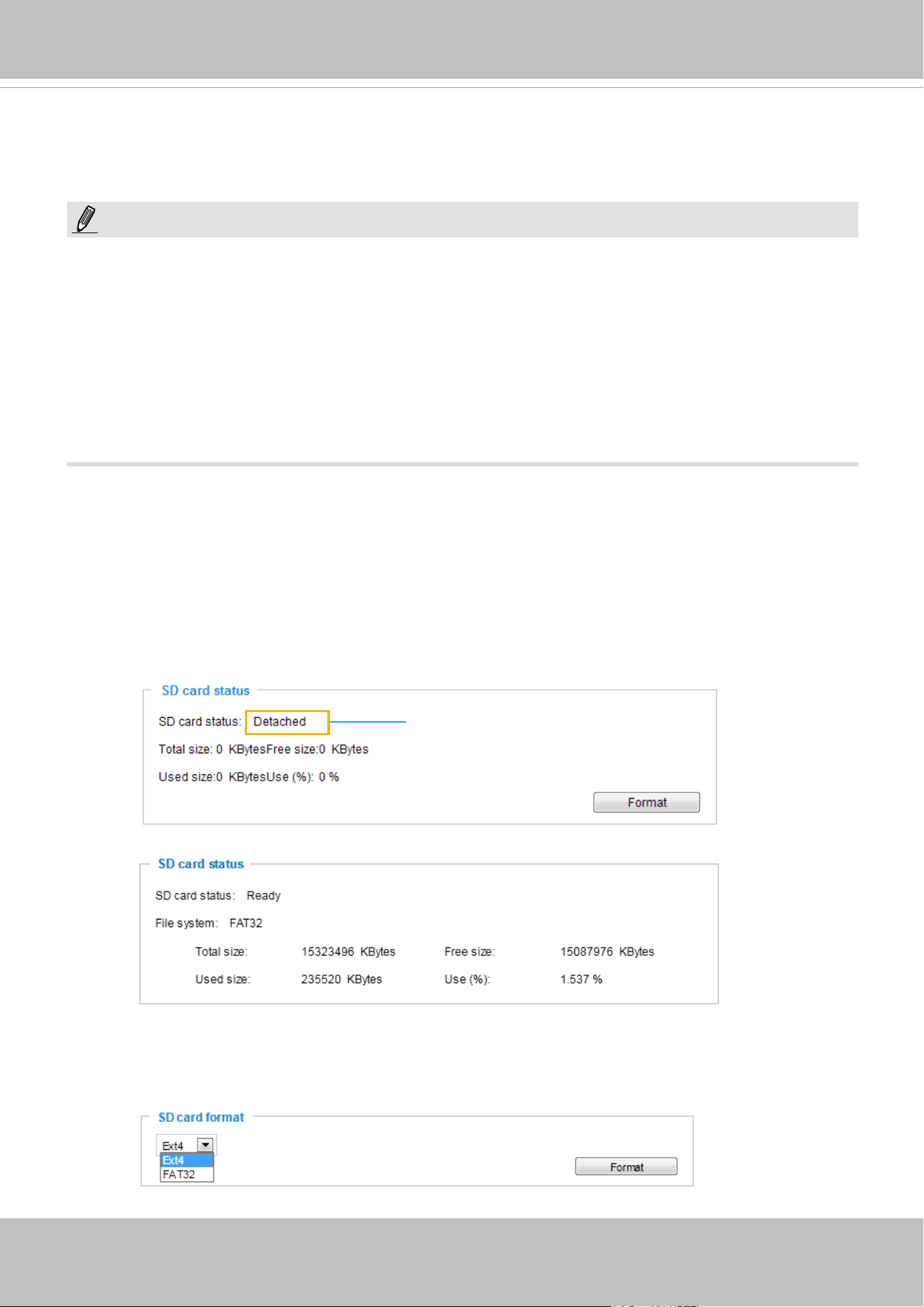
VIVOTEK
User's Manual - 153
Local storage > SD card management
SD card format
The Linux kernel EXT4 file system format applies to SD card larger than 32GB. However, if EXT4 is
applied, the computers running Windows will not be able to access the contents on the SD card unless
using some 3rd-party software.
This section explains how to manage the local storage on the Network Camera. Here you can
view SD card status, and implement SD card control.
SD card staus
This column shows the status and reserved space of your SD card. Please remember to format the SD
card when using for the rst time.
no SD card
NOTE:
• It is recommended to turn OFF the recording activity before you remove an SD card from the
camera.
• The lifespan of an SD card is limited. Regular replacement of the SD card can be necessary.
• Camera lesystem takes up several megabytes of memory space. The storage space cannot
be used for recording.
• Using an SD card that already contains data recorded by another device should not be used
in this camera.
• Please do not modify or change the folder names in the SD card. That may result in camera
malfunctions.
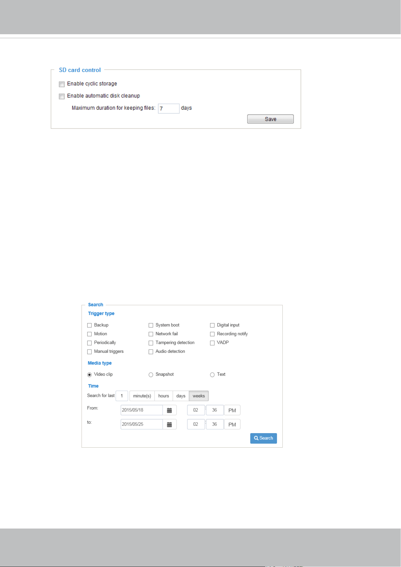
VIVOTEK
154 - User's Manual
SD card control
■ Enable cyclic storage: Check this item if you want to enable cyclic recording. When the maximum
capacity is reached, the oldest le will be overwritten by the latest one.
■ Enable automatic disk cleanup: Check this item and enter the number of days you wish to retain a le.
For example, if you enter “7 days”, the recorded les will be stored on the SD card for 7 days.
Click Save to enable your settings.
Local storage > Content management
This section explains how to manage the content of recorded videos on the Network Camera. Here you
can search and view the records and view the searched results.
Searching and Viewing the Records
This column allows the user to set up search criteria for recorded data. If you do not select any criteria
and click Search button, all recorded data will be listed in the Search Results column.
■ File attributes: Select one or more items as your search criteria.
■ Trigger time: Manually enter the time range you want to search for contents created at a specic point
in time.
Click Search and the recorded data corresponding to the search criteria will be listed in Search Results
window.
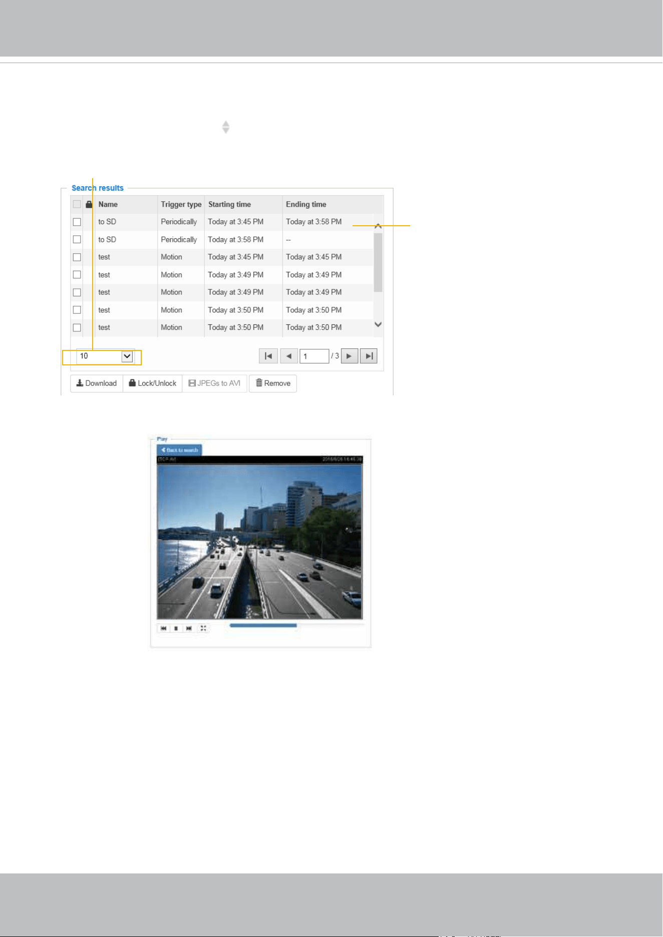
VIVOTEK
User's Manual - 155
Search Results
The following is an example of search results. There are four columns: Trigger time, Media type,
Trigger type, and Locked. Click
to sort the search results in either direction.
Numbers of entries displayed
on one page
Click to open a live view
■ Play: Click on a search result which will highlight the selected item. A Play window will appear on top
for immediate review of the selected le.
For example:
■ Download: Click on a search result to highlight the selected item in purple as shown above. Then click
the Download button and a le download window will pop up for you to save the le.
■ JPEGs to AVI: This functions only applies to “JPEG“ format les such as snapshots. You can select
several snapshots from the list, then click this button. Those snapshots will be converted into an AVI
le.
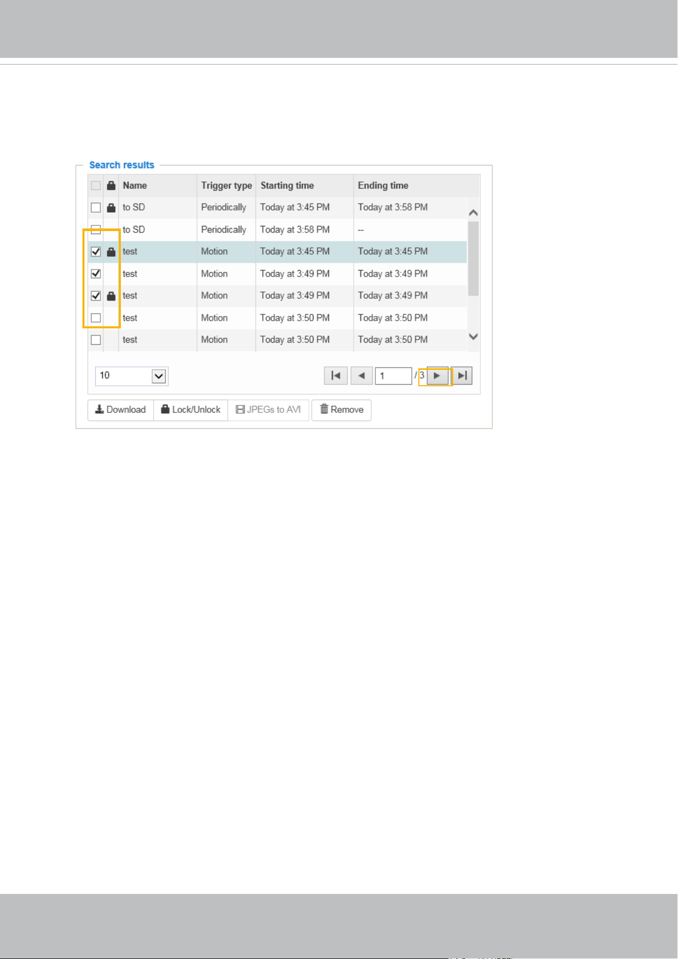
VIVOTEK
156 - User's Manual
■ Lock/Unlock: Select the checkbox in front of a desired search result, then click this button. The selected
items will become Locked, which will not be deleted during cyclic recording. You can click again to
unlock the selections.
For example:
■ Remove: Select the desired search results, then click this button to delete the les.
Click to switch
pages

VIVOTEK
User's Manual - 157
Appendix
URL Commands for the Network Camera
1. Overview
For some customers who already have their own web site or web control application, the Network
Camera/Video Server can be easily integrated through URL syntax. This section specifies the external
HTTP-based application programming interface. The HTTP-based camera interface provides the
functionality to request a single image, control camera functions (PTZ, output relay etc.), and get and set
internal parameter values. The image and CGI-requests are handled by the built-in Web server.
2. Style Convention
In URL syntax and in descriptions of CGI parameters, text within angle brackets denotes content that
is to be replaced with either a value or a string. When replacing the text string, the angle brackets
should also be replaced. An example of this is the description of the name for the server, denoted with
<servername> in the URL syntax description below, that is replaced with the string myserver in the URL
syntax example further down in the page.
URL syntax is denoted with the word "Syntax:" written in bold face followed by a box with the referenced
syntax as shown below. For example, name of the server is written as <servername> and is intended to
be replaced with the name of the actual server. This can either be a name, e.g., "mywebcam" or "thecam.
adomain.net" or the associated IP number for the server, e.g., 192.168.0.220.
Syntax:
http://<servername>/cgi-bin/viewer/video.jpg
Description of returned data is written with "Return:" in bold face followed by the returned data in a box. All data is
returned in HTTP format, i.e., each line is separated with a Carriage Return and Line Feed (CRLF) printed as \r\n.
Return:
HTTP/1.0 <HTTP code> <HTTP text>\r\n
URL syntax examples are written with "Example:" in bold face followed by a short description and a light grey box
with the example.
Example: request a single snapshot image
http://mywebserver/cgi-bin/viewer/video.jpg
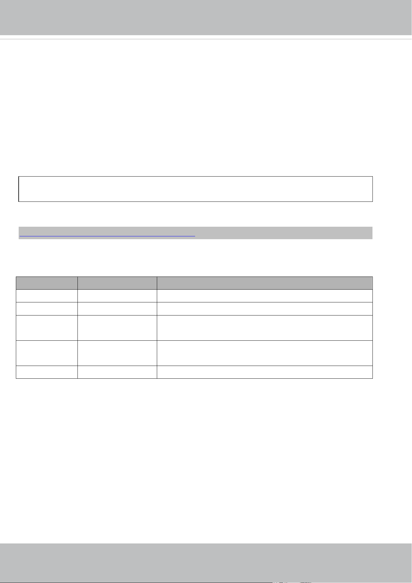
VIVOTEK
158 - User's Manual
3. General CGI URL Syntax and Parameters
CGI parameters are written in lower-case and as one word without any underscores or other separators. When the
CGI request includes internal camera parameters, these parameters must be written exactly as they are named in
the camera or video server. The CGIs are organized in functionally-related directories under the cgi-bin directory.
The file extension .cgi is required.
Syntax:
http://<servername>/cgi-bin/<subdir>[/<subdir>...]/<cgi>.<ext>
[?<parameter>=<value>[&<parameter>=<value>...]]
Example: Set digital output #1 to active
http://mywebserver/cgi-bin/dido/setdo.cgi?do1=1
4. Security Level
SECURITY LEVEL SUB-DIRECTORY DESCRIPTION
0 anonymous Unprotected.
1 [view] viewer Can view, listen, and talk to camera.
4 [operator] operator Operator access rights can modify most of the camera’s parameters
except some privileges and network options.
6 [admin] admin Administrator access rights can fully control the camera’s
operations.
7 N/A Internal APIs. Unable to be changed by any external interfaces.
A viewer account can access all APIs with security level 0 and 1. An operator account can access all APIs with
security level 0, 1, or 4. An admin account can access all APIs except internal APIs.
Access management is based on the URL directory structure and is described in following paragraphs.

VIVOTEK
User's Manual - 159
5. Get Server Parameter Values
Note: The access right depends on the URL directory.
Method: GET/POST
Syntax:
http://<servername>/cgi-bin/anonymous/getparam.cgi?[<parameter>]
[&<parameter>…]
http://<servername>/cgi-bin/viewer/getparam.cgi?[<parameter>]
[&<parameter>…]
http://<servername>/cgi-bin/operator/getparam.cgi?[<parameter>]
[&<parameter>…]
http://<servername>/cgi-bin/admin/getparam.cgi?[<parameter>]
[&<parameter>…]
Where the <parameter> should be <group>[_<name>] or <group>[.<name>]. If you do not specify any
parameters, all the parameters on the server will be returned. If you specify only <group>, the parameters
oftherelated group will be returned.
When querying parameter values, the current parameter values are returned.
A successful control request returns parameter pairs as follows:
Return:
HTTP/1.0 200 OK\r\n
Content-Type: text/html\r\n
Context-Length: <length>\r\n
\r\n
<parameter pair>
where<parameter pair> is
<parameter>=<value>\r\n
[<parameter pair>]
<length> is the actual length of content.
Example: Request IP address and its response
Request:

VIVOTEK
160 - User's Manual
http://192.168.0.123/cgi-bin/admin/getparam.cgi?network_ipaddress
Response:
HTTP/1.0 200 OK\r\n
Content-Type: text/html\r\n
Context-Length: 33\r\n
\r\n
network.ipaddress=192.168.0.123\r\n
6. Set Server Parameter Values
Note: The access right depends on the URL directory.
Method: GET/POST
Syntax:
http://<servername>/cgi-bin/anonymous/setparam.cgi? <parameter>=<value>
[&<parameter>=<value>…][&return=<return page>]
http://<servername>/cgi-bin/viewer/setparam.cgi? <parameter>=<value>
[&<parameter>=<value>…][&return=<return page>]
http://<servername>/cgi-bin/operator/setparam.cgi? <parameter>=<value>
[&<parameter>=<value>…][&return=<return page>]
http://<servername>/cgi-bin/admin/setparam.cgi? <parameter>=<value>
[&<parameter>=<value>…][&return=<return page>]
PARAMETER DESCRIPTION
<parameter>
A full path like: "videoin_c0_s0_h264_resolution", "videoin_c0_s0_h264_maxframe", etc.
<value>
The assigned <value> to the <parameter>.
<return page>
Redirect to the page <return page>after the <parameter> is assigned. The <return page>can
be a full URL path or relative path according to the current path. If you omit this parameter, it will
redirect to an empty page.
(Note: The return page can be a general HTML file (.htm, .html). It cannot be a CGI command or
have any extra parameters. This parameter must be placed at the end of the parameter list.
Return:
HTTP/1.0 200 OK\r\n

VIVOTEK
User's Manual - 161
Content-Type: text/html\r\n
Context-Length: <length>\r\n
\r\n
<parameter pair>
where<parameter pair> is
<parameter>=<value>\r\n
[<parameter pair>]
Only the parameters that you set and are readable will be returned.
Example: Set the IP address of server to 192.168.0.123:
Request:
http://myserver/cgi-bin/admin/setparam.cgi?network_ipaddress=192.168.0.123
Response:
HTTP/1.0 200 OK\r\n
Content-Type: text/html\r\n
Context-Length: 33\r\n
\r\n
network.ipaddress=192.168.0.123\r\n
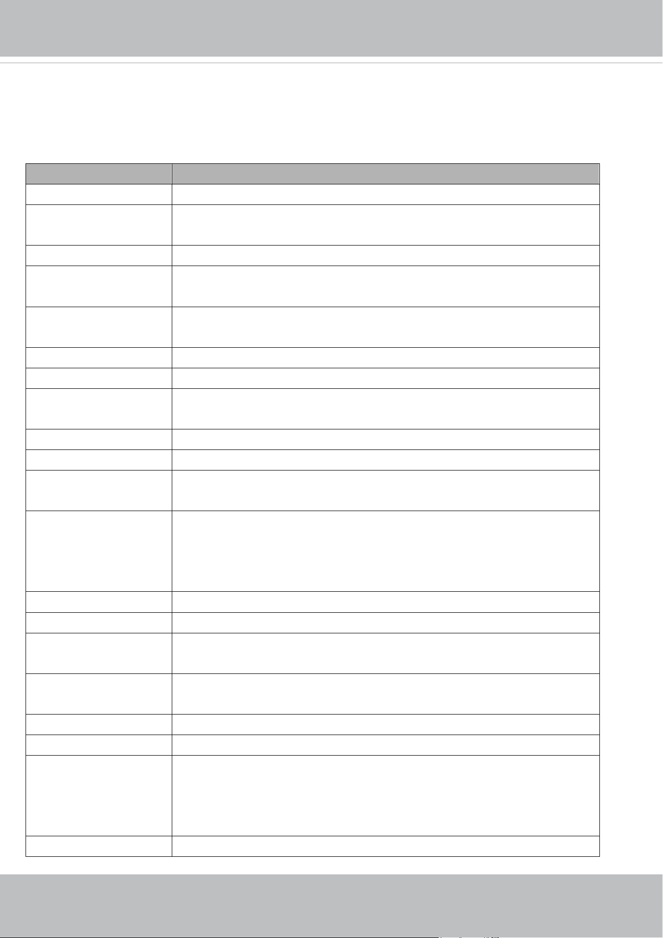
VIVOTEK
162 - User's Manual
7. Available parameters on the server
Valid values:
VALID VALUES DESCRIPTION
string[<n>] Text strings shorter than ‘n’ characters. The characters “,’,<,>,& are invalid.
string[n~m] Text strings longer than `n’ characters and shorter than `m’ characters. The
characters “,’,<,>,& are invalid.
password[<n>] The same as string but displays‘*’ instead.
<integer> Any single integer number in 32-bits.
The range is -2147483648~2147483647.
<positive integer> Any single positive integer number in 32-bits.
The range is 1~ 4294967295.
<m> ~ <n> Any number between ‘m’ and ‘n’.
domain name[<n>] A string limited to a domain name shorter than ‘n’ characters (eg. www.ibm.com).
email address [<n>] A string limited to an email address shorter than ‘n’ characters (eg.
joe@www.ibm.com).
<ip address> A string limited to an IP address (eg. 192.168.1.1).
<mac address> A string limited to contain a MAC address without hyphens or colons.
<boolean> A boolean value of 1 or 0 represents [Yes or No], [True or False], [Enable or
Disable].
<value1>,
<value2>,
<value3>,
…
Enumeration. Only given values are valid.
blank A blank string.
everything inside <> A description
integer primary key SQLite data type. A 32-bit signed integer. The value is assigned a unique integer by
the server.
<text> SQLite data type. The value is a text string, stored using the database encoding
(UTF-8, UTF-16BE or UTF-16-LE).
<coordinate> x, y coordinate (eg. 0,0)
<window size> window width and height (eg. 800x600)
<W,H> The format for coordinate in 2D.
W is the pixel number of width.
H is the pixel number of height.
EX: (176,144)
<WxH> The format for resolution.

VIVOTEK
User's Manual - 163
W is the pixel number of width.
H is the pixel number of height.
Ex: 1920x1080, 2048x1536
available The API is listed in product WebAPIs.
non-available The API is not in product WebAPIs.
valid The API is listed in product WebAPIs, and is functional.
non-valid The API is listed in product WebAPIs, but is malfunction in this status.
<decimal>
Any decimal number expressed in 32-bits ranging from 1.18e-38~3.40e+38.
NOTE: The camera should not be restarted when parameters are changed.

VIVOTEK
164 - User's Manual
7.1system
Group: system
NAME VALUE SECURITY
(get/set)
DESCRIPTION
hostname string[64] 1/6 Host name of server
(Network Camera,
Wireless Network Camera,
Video Server,
Wireless Video Server).
ledoff <boolean> 6/6 Turn on (0) or turn off (1) all led indicators.
date <YYYY/MM/DD>,
keep,
auto
6/6 Current date of system. Set to ‘keep’ to keep
date unchanged. Set to ‘auto’ to use NTP to
synchronize date.
time <hh:mm:ss>,
keep,
auto
6/6 Current time of the system. Set to ‘keep’ to
keep time unchanged. Set to ‘auto’ to use NTP
to synchronize time.
datetime <MMDDhhmmYYYY
.ss>
6/6 Another current time format of the system.
ntp <domain name>,
<ip address>,
<blank>
6/6 NTP server.
*Do not use “skip to invoke default server” for
default value.
timezoneindex -489 ~ 529 6/6 Indicate timezone and area.
-480: GMT-12:00 Eniwetok, Kwajalein
-440: GMT-11:00 Midway Island, Samoa
-400: GMT-10:00 Hawaii
-360: GMT-09:00 Alaska
-320: GMT-08:00 Las Vegas, San_Francisco,
Vancouver
-280: GMT-07:00 Mountain Time, Denver
-281: GMT-07:00 Arizona
-240: GMT-06:00 Central America, Central
Time, Mexico City, Saskatchewan
-200: GMT-05:00 Eastern Time, New York,
Toronto
-201: GMT-05:00 Bogota, Lima, Quito, Indiana
-180: GMT-04:30 Caracas
-160: GMT-04:00 Atlantic Time, Canada, La
Paz, Santiago

VIVOTEK
User's Manual - 165
-140: GMT-03:30 Newfoundland
-120: GMT-03:00 Brasilia, Buenos Aires,
Georgetown, Greenland
-80: GMT-02:00 Mid-Atlantic
-40: GMT-01:00 Azores, Cape_Verde_IS.
0: GMT Casablanca, Greenwich Mean Time:
Dublin,
Edinburgh, Lisbon, London
40: GMT 01:00 Amsterdam, Berlin, Rome,
Stockholm, Vienna, Madrid, Paris
41: GMT 01:00 Warsaw, Budapest, Bern
80: GMT 02:00 Athens, Helsinki, Istanbul, Riga
81: GMT 02:00 Cairo
82: GMT 02:00 Lebanon, Minsk
83: GMT 02:00 Israel
120: GMT 03:00 Baghdad, Kuwait, Riyadh,
Moscow, St. Petersburg, Nairobi
121: GMT 03:00 Iraq
140: GMT 03:30 Tehran
160: GMT 04:00 Abu Dhabi, Muscat, Baku,
Tbilisi, Yerevan
180: GMT 04:30 Kabul
200: GMT 05:00 Ekaterinburg, Islamabad,
Karachi, Tashkent
220: GMT 05:30 Calcutta, Chennai, Mumbai,
New Delhi
230: GMT 05:45 Kathmandu
240: GMT 06:00 Almaty, Novosibirsk, Astana,
Dhaka, Sri Jayawardenepura
260: GMT 06:30 Rangoon
280: GMT 07:00 Bangkok, Hanoi, Jakarta,
Krasnoyarsk
320: GMT 08:00 Beijing, Chongging, Hong
Kong, Kuala Lumpur, Singapore, Taipei
360: GMT 09:00 Osaka, Sapporo, Tokyo,
Seoul, Yakutsk
380: GMT 09:30 Adelaide, Darwin
400: GMT 10:00 Brisbane, Canberra,
Melbourne, Sydney, Guam, Vladivostok
440: GMT 11:00 Magadan, Solomon Is., New

VIVOTEK
166 - User's Manual
Caledonia
480: GMT 12:00 Aucklan, Wellington, Fiji,
Kamchatka, Marshall Is.
520: GMT 13:00 Nuku'Alofa
daylight_enable <boolean> 6/6 Enable automaticdaylight saving time in time
zone.
daylight_dstactualmode <positive integer> 6/7 Check if current time is under daylight saving
time.
(Used internally)
daylight_auto_begintime string[19] 6/7 Display the current daylight saving start time.
daylight_auto_endtime string[19] 6/7 Display the current daylight saving end time.
daylight_timezones string 6/6 List time zone index which support daylight
saving time.
updateinterval 0,
3600,
86400,
604800,
2592000
6/6 0 to Disable automatic time adjustment,
otherwise, it indicates the seconds between
NTP automatic update intervals.
restore 0,
<positive integer>
7/6 Restore the system parameters to default
values after <value> seconds.
reset 0,
<positive integer>
7/6 Restart the server after <value> seconds if
<value> is non-negative.
restoreexceptnet 0,
<positive integer>
7/6 Restore the system parameters to default
values except (ipaddress, subnet, router,
dns1, dns2, pppoe).
This command can cooperate with other
“restoreexceptXYZ” commands. When
cooperating with others, the system
parameters will be restored to the default
value except for a union of the combined
results.
restoreexceptdst 0,
<positive integer>
7/6 Restore the system parameters to default
values except all daylight saving time settings.
This command can cooperate with other
“restoreexceptXYZ” commands. When
cooperating with others, the system
parameters will be restored to default values
except for a union of combined results.
restoreexceptlang 0,
<positive integer>
7/6 Restore the system parameters to default
values except the custom language file the

VIVOTEK
User's Manual - 167
user has uploaded.
This command can cooperate with other
“restoreexceptXYZ” commands. When
cooperating with others, the system
parameters will be restored to the default
value except for a union of the combined
results.
restoreexceptvadp 0,
<positive integer>
7/6 Restore the system parameters to default
values except the vadp parameters and VADP
modules that stored in the system.
This command can cooperate with other
“restoreexceptXYZ” commands. When
cooperating with others, the system
parameters will be restored to the default
value except for a union of the combined
results.
restoreexceptfocusvalue 0,
<positive integer>
7/6 Restore the system parameters to default
values except zoom and focus value.
This command can cooperate with other
“restoreexceptXYZ” commands. When
cooperating with others, the system
parameters will be restored to the default
value except for a union of the combined
results.
* Only available when
"capability_image_c<0~(n-1)>_remotefocus"
!= 0.
7.1.1 system.info
Subgroup of system: info (The fields in this group are unchangeable.)
NAME VALUE SECURITY
(get/set)
DESCRIPTION
modelname string[40] 0/7 Internal model name of the server
extendedmodelname string[40] 0/7 ODM specific model name of server (eg.
DCS-5610). If it is not an ODM model, this field
will be equal to “modelname”
serialnumber <mac address> 1/7 12 characters MAC address (without hyphens).
firmwareversion string[40] 0/7 Firmware version, including model, company,
and version number in the
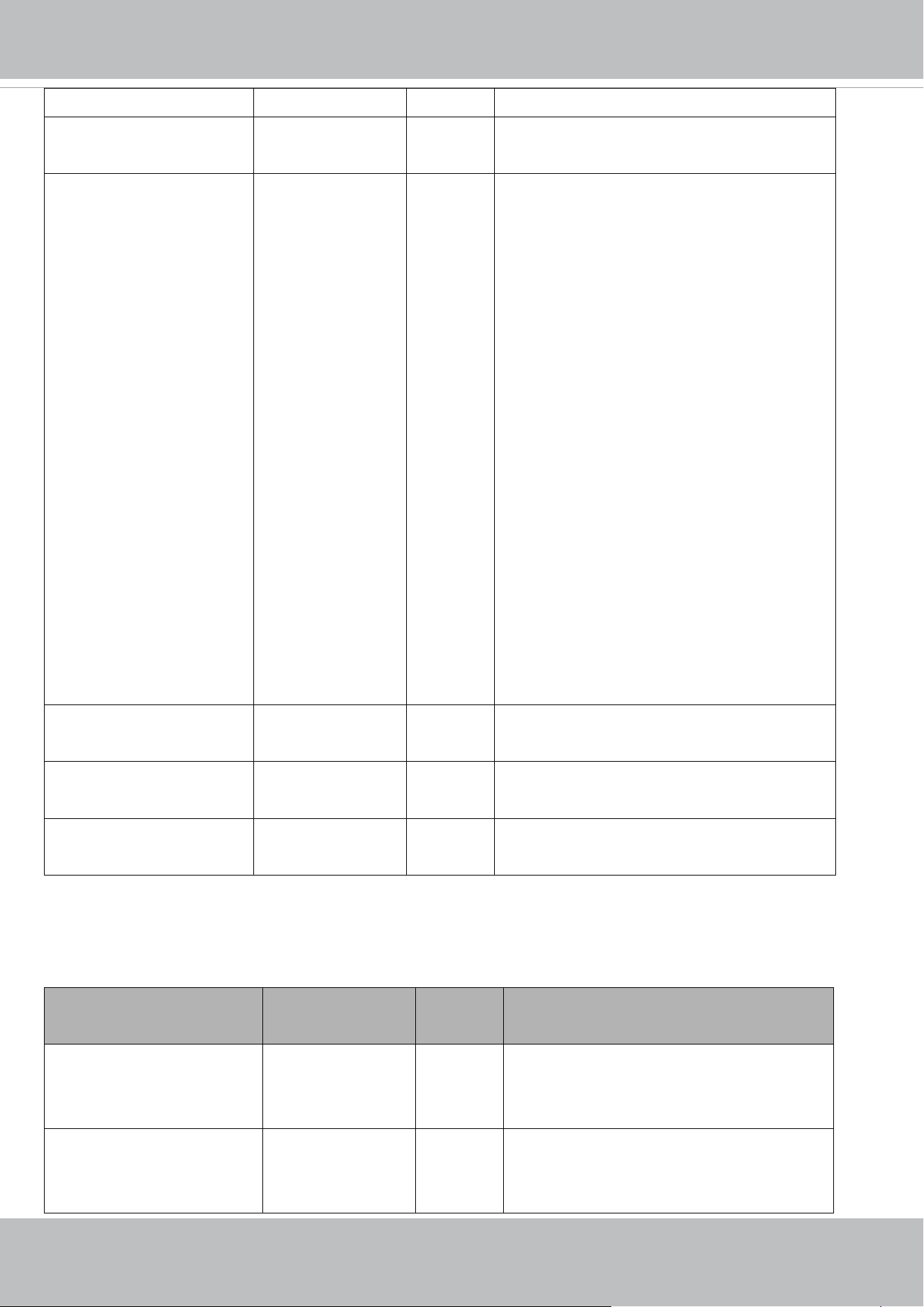
VIVOTEK
168 - User's Manual
format:<MODEL-BRAND-VERSION>
language_count <positive integer> 0/7 Number of webpage languages available on
the server.
language_i<0~(count-1)> string[16]
language_i0 :
English
language_i1 :
Deutsch
language_i2 :
Español
language_i3 :
Français
language_i4 :
Italiano
language_i5 : 日本
語
language_i6 :
Português
language_i7 : 简体
中文
language_i8 : 繁體
中文
0/7 Available language lists.
customlanguage_maxcoun
t
0,<positive
integer>
0/6 Maximum number of custom languages
supported on the server.
customlanguage_count 0,<positive
integer>
0/6 Number of custom languages which have been
uploaded to the server.
customlanguage_i<0~(ma
xcount-1)>
string 0/6 Custom language name.
7.2status
Group: status
NAME VALUE SECURITY
(get/set)
DESCRIPTION
di_i<0~(capability_ndi-1)>
<product dependent>
<boolean> 1/7 0 => Inactive, normal
1 => Active, triggered
(capability.ndi > 0)
do_i<0~(capability_ndo-1)>
<product dependent>
<boolean> 1/7 0 => Inactive, normal
1 => Active, triggered
(capability.ndo > 0)
VIVOTEK
User's Manual - 169
onlinenum_rtsp 0,<positive
integer>
6/7 Current number of RTSP connections.
onlinenum_httppush 0,<positive
integer>
6/7 Current number of HTTP push server
connections.
onlinenum_sip 0,<positive
integer>
6/7 Current number of SIP connections.
eth_i0 <string> 1/7 Get network information from mii-tool.
vi_i<0~(capability_nvi-1)>
<product dependent>
<boolean> 1/7 Virtual input
0 => Inactive
1 => Active
(capability.nvi > 0)
7.2.1 status per channel
Group: status_c<0~(n-1)> for n channel products
n denotes the value of "capability_nvideoin"
NAME VALUE SECURITY
(get/set)
DESCRIPTION
signal_detect <boolean> 1/7 Indicates whether the video source is
connected or not.
* Only available when capability_videoin_type
is 0 or 1.
signal_type ntsc,pal 1/7 The actual modulation type.
* Only available when capability_videoin_type
is 0 or 1.
7.3digital input behavior define
Group: di_i<0~(n-1)> for n is the value of "capability_ndi"
(capability.ndi > 0)
NAME VALUE SECURITY
(get/set)
DESCRIPTION
normalstate high,
low
1/1 Indicates open circuit or closed circuit
(inactive status)
7.4digital output behavior define
Group: do_i<0~(n-1)> for n is the value of "capability_ndo"
(capability.ndo > 0)
NAME VALUE SECURITY
(get/set)
DESCRIPTION
normalstate open, 1/1 Indicate open circuit or closed circuit (inactive
VIVOTEK
170 - User's Manual
grounded status)
7.5security
Group: security
NAME VALUE SECURITY
(get/set)
DESCRIPTION
privilege_do view, operator,
admin
1/6 Indicate which privileges and above can
control digital output
(capability.ndo > 0)
privilege_camctrl view, operator,
admin
1/6 Indicate which privileges and above can
control PTZ
(capability.ptzenabled > 0 or capability.eptz >
0)
user_i0_name string[64] 6/7 User name of root
user_i<1~20>_name string[64] 6/7 User name
user_i0_pass password[64] 7/6 Root password
user_i<1~20>_pass password[64] 7/6 User password
user_i0_privilege view,
operator,
admin
6/7 Root privilege
user_i<1~20>_ privilege view,
operator,
admin
6/6 User privilege

VIVOTEK
User's Manual - 171
7.6network
Group: network
NAME VALUE SECURITY
(get/set)
DESCRIPTION
preprocess <positive integer> 6/6 An 32-bit integer, each bit can be set
separately as follows:
Bit 0 => HTTP service;
Bit 1=> HTTPS service;
Bit 2=> FTP service;
Bit 3 => Two way audio and RTSP Streaming
service;
To stop service before changing its port
settings. It’s recommended to set this
parameter when change a service port to the
port occupied by another service currently.
Otherwise, the service may fail.
Stopped service will auto-start after changing
port settings.
Ex:
Change HTTP port from 80 to 5556, and
change RTP port for video from 5556 to 20480.
Then, set preprocess=9 to stop both service
first.
”/cgi-bin/admin/setparam.cgi?
network_preprocess=9&network_http_port=
5556& network_rtp_videoport=20480”
type lan,
pppoe
6/6 Network connection type.
resetip <boolean> 6/6 1 => Get ipaddress, subnet, router, dns1,
dns2 from DHCP server at next reboot.
0 => Use preset ipaddress, subnet, rounter,
dns1, and dns2.
ipaddress <ip address> 6/6 IP address of server.
subnet <ip address> 6/6 Subnet mask.
router <ip address> 6/6 Default gateway.
dns1 <ip address> 6/6 Primary DNS server.
VIVOTEK
172 - User's Manual
dns2 <ip address> 6/6 Secondary DNS server.
wins1 <ip address> 6/6 Primary WINS server.
wins2 <ip address> 6/6 Secondary WINS server.
7.6.1 802.1x
Subgroup of network: ieee8021x
(capability.protocol.ieee8021x > 0)
NAME VALUE SECURITY
(get/set)
DESCRIPTION
enable <boolean> 6/6 Enable/disable IEEE 802.1x
eapmethod eap-peap, eap-tls 6/6 Selected EAP method
identity_peap string[64] 6/6 PEAP identity
identity_tls string[64] 6/6 TLS identity
password string[200] 7/6 Password for TLS
privatekeypassword string[200] 7/6 Password for PEAP
ca_exist <boolean> 6/6 CA installed flag
ca_time 0,<positive
integer>
6/7 CA installed time. Represented in EPOCH
ca_size 0,<positive
integer>
6/7 CA file size (in bytes)
certificate_exist <boolean> 6/6 Certificate installed flag (for TLS)
certificate_time 0,<positive
integer>
6/7 Certificate installed time. Represented in
EPOCH
certificate_size 0,<positive
integer>
6/7 Certificate file size (in bytes)
privatekey_exist <boolean> 6/6 Private key installed flag (for TLS)
privatekey_time 0,<positive
integer>
6/7 Private key installed time. Represented in
EPOCH
privatekey_size 0,<positive
integer>
6/7 Private key file size (in bytes)
7.6.2 QOS
Subgroup of network: qos_cos
(capability.protocol.qos.cos > 0)
NAME VALUE SECURITY
(get/set)
DESCRIPTION
enable <boolean> 6/6 Enable/disable CoS (IEEE 802.1p)
vlanid 1~4095 6/6 VLAN ID
video 0~7 6/6 Video channel for CoS
VIVOTEK
User's Manual - 173
audio
<product dependent>
0~7 6/6 Audio channel for CoS
(capability.naudioin > 0)
eventalarm 0~7 6/6 Event/alarm channel for CoS
management 0~7 6/6 Management channel for CoS
eventtunnel 0~7 6/6 Event/Control channel for CoS
Subgroup of network: qos_dscp (capability.protocol.qos.dscp > 0)
NAME VALUE SECURITY
(get/set)
DESCRIPTION
enable <boolean> 6/6 Enable/disable DSCP
video 0~63 6/6 Video channel for DSCP
audio 0~63 6/6 Audio channel for DSCP
(capability.naudioin > 0)
eventalarm 0~63 6/6 Event/alarm channel for DSCP
management 0~63 6/6 Management channel for DSCP
eventtunnel 0~63 6/6 Event/Control channel for DSCP
7.6.3 IPV6
Subgroup of network: ipv6
(capability.protocol.ipv6 > 0)
NAME VALUE SECURITY
(get/set)
DESCRIPTION
enable <boolean> 6/6 Enable IPv6.
addonipaddress <ip address> 6/6 IPv6 IP address.
addonprefixlen 0~128 6/6 IPv6 prefix length.
addonrouter <ip address> 6/6 IPv6 router address.
addondns <ip address> 6/6 IPv6 DNS address.
allowoptional <boolean> 6/6 Allow manually setup of IP address setting.
7.6.4 FTP
Subgroup of network: ftp
NAME VALUE SECURITY
(get/set)
DESCRIPTION
port 21, 1025~65535 6/6 Local ftp server port.
enable <boolean> 6/6 Enable ftp.
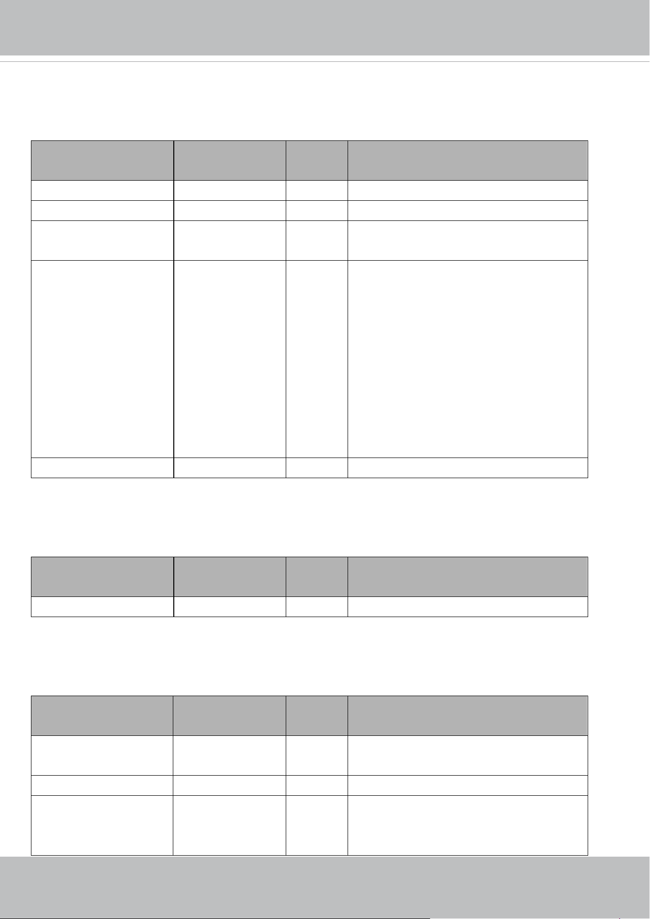
VIVOTEK
174 - User's Manual
7.6.5 HTTP
Subgroup of network: http
NAME VALUE SECURITY
(get/set)
DESCRIPTION
port 80, 1025 ~ 65535 1/6 HTTP port.
alternateport 1025~65535 6/6 Alternate HTTP port.
authmode basic,
digest
1/6 HTTP authentication mode.
s<0~(capability_nmediast
ream-1)>_accessname
<product dependent>
string[32] 1/6 Http server push access name for stream N,
N= 1~ capability.nmediastream.
(capability.protocol.spush_mjpeg =1 and
capability.nmediastream > 0)
The value are shown as
video.mjpg = s0_accessname, (stream1)
video2.mjpg = s1_accessname, (stream2)
video3.mjpg = s2_accessname, (stream3)
video4.mjpg = s3_accessname, (stream4)
etc.
anonymousviewing <boolean> 1/6 Enable anonymous streaming viewing.
7.6.6 HTTPS port
Subgroup of network: https
(capability.protocol.https > 0)
NAME VALUE SECURITY
(get/set)
DESCRIPTION
port 443, 1025 ~ 65535 1/6 HTTPS port.
7.6.7 RTSP
Subgroup of network: rtsp
(capability.protocol.rtsp > 0)
NAME VALUE SECURITY
(get/set)
DESCRIPTION
port 554, 1025 ~ 65535 1/6 RTSP port.
(capability.protocol.rtsp=1)
anonymousviewing <boolean> 1/6 Enable anoymous streaming viewing.
authmode disable,
basic,
digest
1/6 RTSP authentication mode.
(capability.protocol.rtsp=1)

VIVOTEK
User's Manual - 175
s<0~(capability_nmediast
ream-1)>_accessname
<product dependent>
string[32] 1/6 RTSP access name for stream N, N= 1~
capability.nmediastream.
(capability.protocol.spush_mjpeg =1 and
capability.nmediastream > 0)
The value are shown as
live.sdp = s0_accessname, (stream1)
live2.sdp = s1_accessname, (stream2)
live3.sdp = s2_accessname, (stream3)
live4.sdp = s3_accessname, (stream4)
etc.
7.6.7.1 RTSP multicast
Subgroup of network_rtsp_s<0~(n-1)>: multicast n is stream count
NAME VALUE SECURITY
(get/set)
DESCRIPTION
alwaysmulticast <boolean> 4/4 Enable always multicast.
ipaddress <ip address> 4/4 Multicast video IP address.
* We replace
"network_rtsp_s<0~(n-1)>_multicast_ipaddress"
with "
network_rtsp_s<0~(n-1)>_multicast_videoipaddre
ss ".
* Reserved for compatibility, and suggest don't use
this since [httpversion] > 0304a
videoipaddress <ip address> 4/4 Multicast video IP address.
* We support this parameter when the version
number (httpversion) is equal or greater than 0304a.
audioipaddress
<product dependent>
<ip address> 4/4 Multicast audio IP address.
* We support this parameter when the version
number (httpversion) is equal or greater than 0304a.
* Only available when capability_naudioin > 0
metadataipaddress <ip address> 4/4 Multicast metadata IP address.
* We support this parameter when the version
number (httpversion) is equal or greater than 0304a.
videoport 1025 ~ 65535 4/4 Multicast video port.
audioport
<product dependent>
1025 ~ 65535 4/4 Multicast audio port.
* Only available when capability_naudioin > 0
metadataport 1026~65534 4/4 Multicast metadata port.
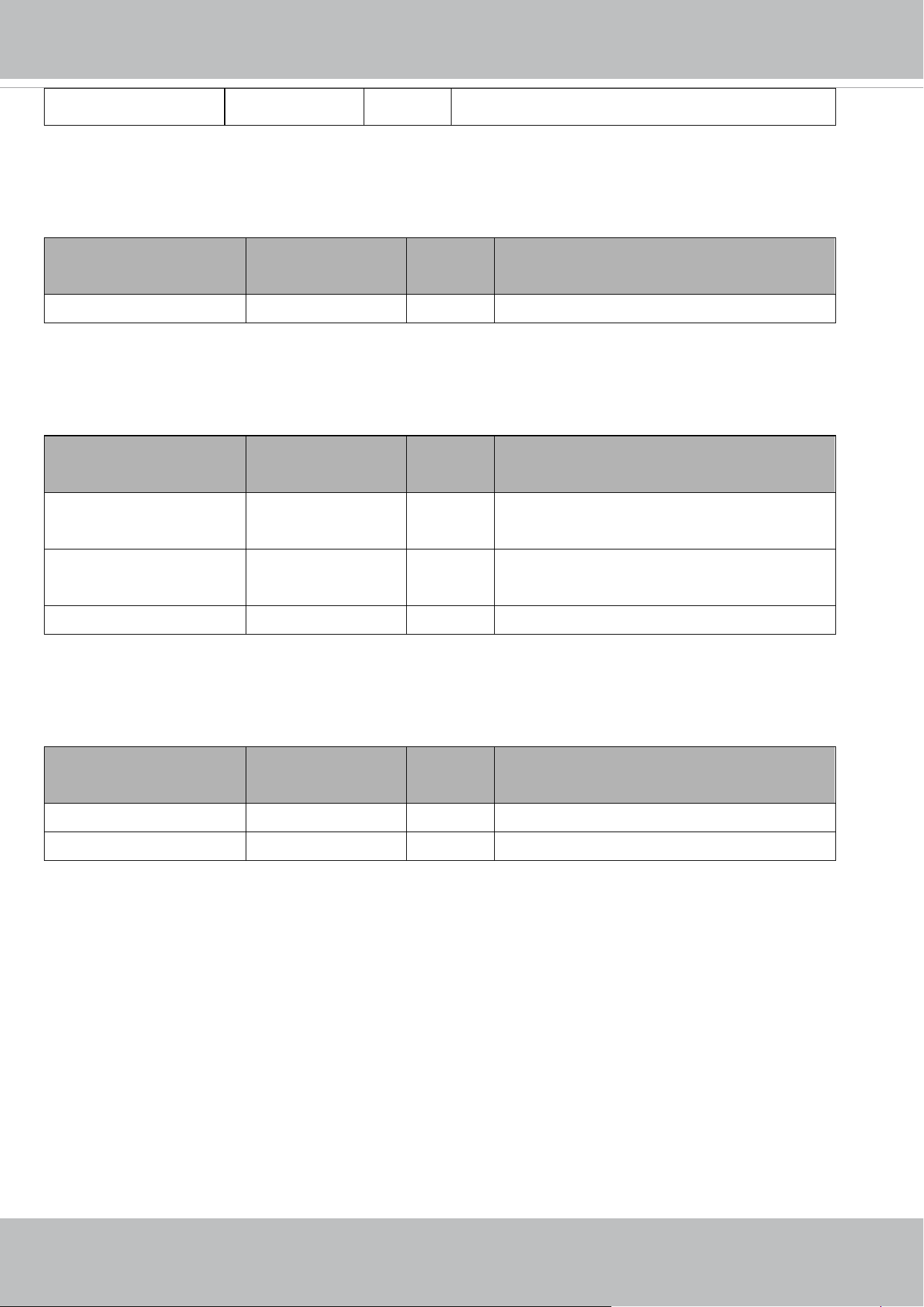
VIVOTEK
176 - User's Manual
ttl 1 ~ 255 4/4 Multicasttime to live value.
7.6.8 SIP port
Subgroup of network: sip
(capability.protocol.sip> 0)
NAME VALUE SECURITY
(get/set)
DESCRIPTION
port 1025 ~ 65535 1/6 SIP port.
7.6.9 RTP port
Subgroup of network: rtp
NAME VALUE SECURITY
(get/set)
DESCRIPTION
videoport 1025 ~ 65535 6/6 Video channel port for RTP.
audioport 1025 ~ 65535 6/6 Audio channel port for RTP.
metadataport 1025 ~ 65535 6/6 Metadata channel port for RTP.
7.6.10 PPPoE
Subgroup of network: pppoe
(capability.protocol.pppoe > 0)
NAME VALUE SECURITY
(get/set)
DESCRIPTION
user string[128] 6/6 PPPoE account user name.
pass password[64] 7/6 PPPoE account password.

VIVOTEK
User's Manual - 177
7.7IP Filter
Group: ipfilter
NAME VALUE SECURITY
(get/set)
DESCRIPTION
enable <boolean> 6/6 Enable access list filtering.
admin_enable <boolean> 6/6 Enable administrator IP address.
admin_ip string[43] 6/6 Administrator IP address.
maxconnection 1~10 6/6 Maximum number of concurrent streaming
connection(s).
type 0, 1 6/6 Ipfilter policy :
0 => allow
1 => deny
ipv4list_i<0~9> Single address: <ip
address>
Network address:
<ip address /
network mask>
Range
address:<start ip
address - end ip
address>
6/6 IPv4 address list.
ipv6list_i<0~9> string[43] 6/6 IPv6 address list.

VIVOTEK
178 - User's Manual
7.8Video input
Group: videoin
NAME VALUE SECURITY
(get/set)
DESCRIPTION
cmosfreq 50, 60 4/4 CMOS frequency.
* Only available when capability_videoin_type
is 2.
whitebalance
<product dependent>
auto,
manual,
rbgain,
widerange,
outdoor,
indoor,
sodiumauto,
etc
(Available values are
listed in
"capability_image_c
<0~(n-1)>_wbmod
e")
4/4 Modes of white balance.
"auto": Auto white balance
"rbgain": Use rgain and bgain to set white
balance manually.
"manual": 2 cases:
a. if "rbgain" is not supported, this means
keep current white balance status.
b. if "rbgain" is supported, "rgain" and
"bgain" are updated to the current values
which is got from white balance module. Then,
act as rbgain mode
"widerange": Auto Tracing White balance
(2000K to 10000K).
"outdoor": auto white balance mode
specifically for outdoor.
"indoor": auto white balance mode
specifically for indoor.
"sodiumauto": sodium vapor lamps.
* Only available when
"capability_image_c<0~(n-1)>_wbmode" !="
-"
exposurelevel 0~12 4/4 Exposure level
"0,12": This range takes the concept from DC's
exposure tuning options. The definition is:
0: EV -2.0
1: EV -1.7
2: EV -1.3
3: EV -1.0
4: EV -0.7
5: EV -0.3

VIVOTEK
User's Manual - 179
6: EV 0
7: EV +0.3
8: EV +0.7
9: EV +1.0
10: EV +1.3
11: EV +1.7
12: EV +2.0
* Only available when
"capability_image_c<0~(n-1)>_exposure_m
ode" !=0
irismode fixed, indoor,
outdoor
<product
independent>
4/4 Control DC-Iris mode.
"outdoor": Auto-setting DC-Iris to get best
quality, but easy to meet rolling or flicker effect
in indoor environment.
"indoor": Avoid rolling and flicker effect first.
"fixed": Open the iris to maximum.
* Only available when
"capability_image_c<0~(n-1)>_iristype"=dci
ris
enableblc
<Not support anymore>
<boolean> 4/4 Enable backlight compensation.
* Not support this parameter anymore when
the version number (httpversion) is equal or
greater than 0301a.
* It's recommanded to use
"exposurewin_c<0~(n-1)>_mode" to switch
on/off BLC.
color 0, 1 4/4 0 =>monochrome
1 => color
* Only available when "
capability_videoin_c<0~(n-1)>_color_suppor
t" is 1.
flip <boolean> 4/4 Flip the image.
mirror <boolean> 4/4 Mirror the image.
rotate 0,90,180,270 1/4 The rotation angle of image.
Support only in Rotation mode.
* Only available when "
capability_videoin_c<0~(n-1)>_rotation"=1
ptzstatus
<Not support anymore>
0,<positive
integer>
1/7 A 32-bit integer, each bit can be set separately
as follows:

VIVOTEK
180 - User's Manual
Bit 0 => Support camera control function;
0(not support), 1(support)
Bit 1 =>Built-in or external camera; 0
(external), 1(built-in)
Bit 2 => Support pan operation; 0(not
support), 1(support)
Bit 3 => Support tilt operation; 0(not
support), 1(support)
Bit 4 => Support zoom operation; 0(not
support), 1(support)
Bit 5 => Support focus operation; 0(not
support), 1(support)(SD/PZ/IZ series only)
text string[64] 1/4 Enclose caption.
imprinttimestamp <boolean> 4/4 Overlay time stamp on video.
minexposure
<product dependent>
<1~32000>,
<5~32000>,
<1~8000>,
<5~8000>,
etc.
* Available value is
listed in
"capability_image_c
<0~(n-1)>_exposu
re_minrange"
4/4 Minimum exposure time
1~32000 => 1s ~ 1/32000s
5~32000 => 1/5s ~ 1/32000s
1~8000 => 1s ~ 1/8000s
5~8000 => 1/5s ~ 1/8000s
etc.
* Only available when
"capability_image_c<0~(n-1)>_exposure_mi
nrange" != "-"
* Only valid when "piris_mode"=manual or
"irismode"=fixed
* Only available when
"capability_image_c<0~(n-1)>_exposure_ra
ngetype" is "twovalues".
maxexposure
<product dependent>
<1~32000>,
<5~32000>,
<1~8000>,
<5~8000>,
etc.
* Available value is
listed in
"capability_image_c
<0~(n-1)>_exposu
4/4 Maximum exposure time
1~32000 => 1s ~ 1/32000s
5~32000 => 1/5s ~ 1/32000s
1~8000 => 1s ~ 1/8000s
5~8000 => 1/5s ~ 1/8000s
etc.
* This parameter may also restrict image
frame rate from sensor due to sensor
generates a frame per exposure time. Ex: If
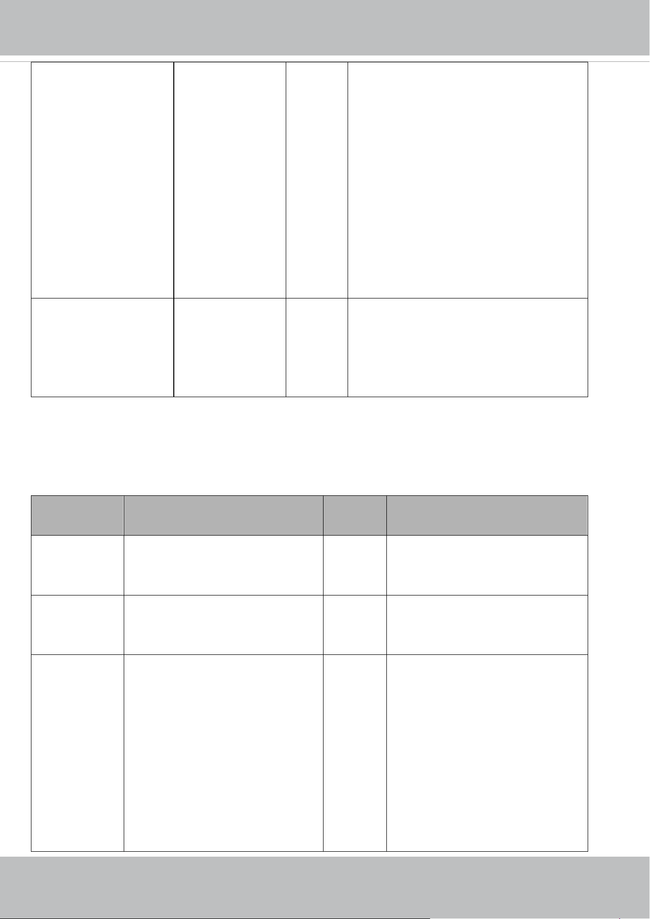
VIVOTEK
User's Manual - 181
re_maxrange" this is set to 1/5s ~ 1/8000s and camera takes
1/5s on the night, then sensor only outputs 5
frame/s.
* Only available when
"capability_image_c<0~(n-1)>_exposure_m
axrange" != "-"
* Only valid when "piris_mode"=manual or
"irismode"=fixed
* Only available when
"capability_image_c<0~(n-1)>_exposure_ra
ngetype" is "twovalues".
enablepreview <boolean> 1/4 Usage for UI of exposure settings. Preview
settings of video profile.
* Only available when
"capability_image_c<0~(n-1)>_exposure_m
ode" !=0
7.8.1 Video input setting per channel
Group: videoin_c<0~(n-1)> for n channel products, and m is stream number
n denotes the value of "capability_nvideoin", m denotes the value of "capability_nmediastream"
NAME VALUE SECURITY
(get/set)
DESCRIPTION
cmosfreq 50, 60 4/4 CMOS frequency.
* Only available when "
capability_videoin_type " is 2
mode 0 ~
"capability_videoin_c<0~(n-1)>_nm
ode"-1
4/4 Indicate the video mode on use.
whitebalance
<product
dependent>
auto,
manual,
rbgain,
widerange,
outdoor,
indoor,
sodiumauto,
etc
(Available values are listed in
4/4 Modes of white balance.
"auto": Auto white balance
"rbgain": Use rgain and bgain to set
white balance manually.
"manual": 2 cases:
a. if "rbgain" is not supported, this
means keep current white balance
status.
b. if "rbgain" is supported, "rgain"
and "bgain" are updated to the current

VIVOTEK
182 - User's Manual
"capability_image_c<0~(n-1)>_wbm
ode")
values which is got from white balance
module. Then, act as rbgain mode
"widerange": Auto Tracing White
balance (2000K to 10000K).
"outdoor": auto white balance mode
specifically for outdoor.
"indoor": auto white balance mode
specifically for indoor.
"sodiumauto": sodium vapor lamps.
* Only available when
"capability_image_c<0~(n-1)>_wbm
ode" !="-"
rgain 0~100 4/4 Manual set rgain value of gain control
setting.
0: Weak <-> 100: Strong
* Only available when "rbgain" is listed
in
"capability_image_c<0~(n-1)>_wbm
ode".
* Only valid when
"videoin_c<0~(n-1)>_whitebalance"
!= auto
* Normalized range.
bgain 0~100 4/4 Manual set bgain value of gain control
setting.
0: Weak <-> 100: Strong
* Only available when "rbgain" is listed
in
"capability_image_c<0~(n-1)>_wbm
ode".
* Only valid when
"videoin_c<0~(n-1)>_whitebalance"
!= auto
* Normalized range.
exposurelevel 0~12 4/4 Exposure level
"0,12": This range takes the concept
from DC's exposure tuning options.

VIVOTEK
User's Manual - 183
The definition is:
0: EV -2.0
1: EV -1.7
2: EV -1.3
3: EV -1.0
4: EV -0.7
5: EV -0.3
6: EV 0
7: EV +0.3
8: EV +0.7
9: EV +1.0
10: EV +1.3
11: EV +1.7
12: EV +2.0
* Only available when
"capability_image_c<0~(n-1)>_expo
sure_mode" !=0
exposuremode
<product
dependent>
auto,
shutterpriority,
irispriority,
qualitypriority,
manual,
etc
(Available options are list in
"capability_image_c<0~(n-1)>_expo
sure_modetype")
4/4 Select exposure mode.
"auto": Automatically adjust the Iris,
Gain and Shutter Speed to fit the
exposure level.
"shutterpriority": Manually adjust
with variable Shutter Speed, and keep
adjusting Iris, Gain automatically.
"irispriority": Manually adjust with
variable Iris, and keep adjusting Gain
and Shutter speed automatically.
"qualitypriority": Automatically
adjust the Iris, Gain and Shutter Speed
by VIVOTEK quality algorithm.
"manual": Manually adjust with
variable Shutter, Iris and Gain.
* We support this parameter when the
version number (httpversion) is equal
or greater than 0302a.
* Only available when
"capability_image_c<0~(n-1)>_expo
sure_mode" !=0

VIVOTEK
184 - User's Manual
irismode fixed, indoor, outdoor
<product dependent>
4/4 Control DC-Iris mode.
"outdoor": Auto-setting DC-Iris to
get best quality, but easy to meet
rolling or flicker effect in indoor
environment.
"indoor": Avoid rolling and flicker
effect first.
"fixed": Open the iris to maximum.
* Only available when
"capability_image_c<0~(n-1)>_iristy
pe"=dciris
piris_mode
<product
dependent>
manual, indoor, outdoor,- 1/4 Control P-Iris mode.
"outdoor": Auto-setting P-Iris to get
best quality, but easy to meet rolling or
flicker effect in indoor environment.
"indoor": Avoid rolling and flicker
effect first.
"manual": Manual set P-Iris by
"piris_position".
"-": not support. (only available when
"capability_image_c<0~(n-1)>_sens
ortype" is "smartsensor")
* Only available when
"capability_image_c<0~(n-1)>_iristy
pe"=piris
piris_position
<product
dependent>
1~100 1/4 Manual set P-Iris.
1: Open <-> 100: Close
* Only valid when
"piris_mode"=manual or
"capability_image_c<0~(n-1)>_sens
ortype" is "smartsensor"
* Only available when
"capability_image_c<0~(n-1)>_iristy
pe"=piris
enableblc
<Not support
anymore>
<boolean> 4/4 Enable backlight compensation
* Not support this parameter anymore
when the version number
(httpversion) is equal or greater than
0301a.

VIVOTEK
User's Manual - 185
* It's recommanded to use
"exposurewin_c<0~(n-1)>_mode" to
switch on/off BLC.
maxgain 0~100 4/4 Maximum gain value.
0: Low <-> 100: High
* Only available when
"capability_image_c<0~(n-1)>_agc_
maxgain" != "-"
* Only valid when
"piris_mode"=manual or
"irismode"=fixed
* Normalized range.
* Only available when
"capability_image_c<0~(n-1)>_expo
sure_rangetype" is "twovalues".
mingain 0~100 4/4 Minimum gain value.
0: Low <-> 100: High
* Only available when
"capability_image_c<0~(n-1)>_agc_
mingain" != "-"
* Only valid when
"piris_mode"=manual or
"irismode"=fixed
* Normalized range.
* Only available when
"capability_image_c<0~(n-1)>_expo
sure_rangetype" is "twovalues".
gainvalue 0~100 4/4 Gain value.
0: Low <-> 100: High
* Only available when
"capability_image_c<0~(n-1)>_agc_
maxgain" != "-" and
"capability_image_c<0~(n-1)>_expo
sure_rangetype" is "onevalue".
* Normalized range.
* We support this parameter when the

VIVOTEK
186 - User's Manual
version number (httpversion) is equal
or greater than 0302a.
color 0, 1 4/4 0 =>monochrome
1 => color
* Only available when "
capability_videoin_c<0~(n-1)>_color
_support" is 1.
flip <boolean> 4/4 Flip the image.
mirror <boolean> 4/4 Mirror the image.
rotate 0,90,180,270 1/4 The rotation angle of image.
Support only in Rotation mode
(capability_videoin_c<0~(n-1)>_rota
tion=1)
ptzstatus
<Not support
anymore>
0,<positive integer> 1/7 A 32-bit integer, each bit can be set
separately as follows:
Bit 0 => Support camera control
function; 0(not support), 1(support)
Bit 1 =>Built-in or external camera;
0 (external), 1(built-in)
Bit 2 => Support pan operation;
0(not support), 1(support)
Bit 3 => Support tilt operation; 0(not
support), 1(support)
Bit 4 => Support zoom operation;
0(not support), 1(support)
Bit 5 => Support focus operation;
0(not support), 1(support)(SD/PZ/IZ
series only)
text string[64] 1/4 Enclose caption.
imprinttimesta
mp
<boolean> 4/4 Overlay time stamp on video.
textonvideo_po
sition
top, bottom 4/4 Text on video string position
textonvideo_siz
e
20~40 4/4 Text on video font size
textonvideo_fon
tpath
/usr/share/font/Default.ttf,
/mnt/flash2/upload.ttf
4/4 Choose camera default font file
(/usr/share/font/Default.ttf) or user
uploaded font
file(/mnt/flash2/upload.ttf).
textonvideo_upl Depends on the font file name 1/7 Show the uploaded font file name.

VIVOTEK
User's Manual - 187
oadfilename uploaded by user
minexposure
<product
dependent>
<1~32000>,
<5~32000>,
<1~8000>,
<5~8000>,
etc.
* Available value is listed in
"capability_image_c<0~(n-1)>_expo
sure_minrange"
4/4 Minimum exposure time
1~32000 => 1s ~ 1/32000s
5~32000 => 1/5s ~ 1/32000s
1~8000 => 1s ~ 1/8000s
5~8000 => 1/5s ~ 1/8000s
etc.
* Only available when
"capability_image_c<0~(n-1)>_expo
sure_minrange" != "-"
* Only valid when
"piris_mode"=manual or
"irismode"=fixed
* Only available when
"capability_image_c<0~(n-1)>_expo
sure_rangetype" is "twovalues".
maxexposure
<product
dependent>
<1~32000>,
<5~32000>,
<1~8000>,
<5~8000>,
etc.
* Available value is listed in
"capability_image_c<0~(n-1)>_expo
sure_maxrange"
4/4 Maximum exposure time
1~32000 => 1s ~ 1/32000s
5~32000 => 1/5s ~ 1/32000s
1~8000 => 1s ~ 1/8000s
5~8000 => 1/5s ~ 1/8000s
etc.
* This parameter may also restrict
image frame rate from sensor due to
sensor generates a frame per
exposure time. Ex: If this is set to 1/5s
~ 1/8000s and camera takes 1/5s on
the night, then sensor only outputs 5
frame/s.
* Only available when
"capability_image_c<0~(n-1)>_expo
sure_maxrange" != "-"
* Only valid when
"piris_mode"=manual or
"irismode"=fixed
* Only available when
"capability_image_c<0~(n-1)>_expo

VIVOTEK
188 - User's Manual
sure_rangetype" is "twovalues".
shuttervalue
<product
dependent>
<1~32000>,
<5~32000>,
<1~8000>,
<5~8000>,
etc.
* Available value is listed in
"capability_image_c<0~(n-1)>_expo
sure_maxrange"
4/4 Exposure time
1~32000 => 1s ~ 1/32000s
5~32000 => 1/5s ~ 1/32000s
1~8000 => 1s ~ 1/8000s
5~8000 => 1/5s ~ 1/8000s
etc.
* This parameter may also restrict
image frame rate from sensor due to
sensor generates a frame per
exposure time. Ex: If this is set to 1/5s
~ 1/8000s and camera takes 1/5s on
the night, then sensor only outputs 5
frame/s.
* Only available when
"capability_image_c<0~(n-1)>_expo
sure_maxrange" != "-" and
"capability_image_c<0~(n-1)>_expo
sure_rangetype" is "onevalue".
* We support this parameter when the
version number (httpversion) is equal
or greater than 0302a.
enablepreview <boolean> 1/4 Usage for UI of exposure settings.
Preview settings of video profile.
* Only available when
"capability_image_c<0~(n-1)>_expo
sure_mode" !=0
crop_position <coordinate>
(x,y)
1/7 Crop left-top corner coordinate.
crop_size <window size>
(WxH)
1/7 Crop width and height.
(width must be 16x or 32x and height
must be 8x)
zoomratiodispla
y
<boolean> 1/4 Indicates multiple of zoom in is
“on-screen display” or not.
* We support this parameter when the

VIVOTEK
User's Manual - 189
version number (httpversion) is equal
or greater than 0302a.
bracketing_level 1~100 4/4 The total available lists
(capability_image_c<0~(
n-1)>_exposure_bracketi
ng_range) will be
normalized to 1~100
scale.
* For example, the total
available list is 7.
(2x,3x,4x,5x,6x,7x,8x)
1 ~ 14 that
correspond with 2x.
15 ~ 30 that
correspond with 3x.
*Only available when
"capability_image_c<0~(n-1)>_expo
sure_bracketing_mode"=1.
* We support this parameter when the
version number (httpversion) is equal
or greater than 0310a.
s<0~(m-1)>_e
nableeptz
<boolean> 4/4 Indicate whether stream supprts eptz
or not
s<0~(m-1)>_c
odectype
Listed at "capability_videoin_codec"
Possible values are: mjpeg,
h264,h265
<product dependent>
1/4 Codec type for this stream
s<0~(m-1)>_re
solution
Available options are list in
"capability_videoin_c<0~(n-1)>_reso
lution".
Besides, available options is referred
to
"capability_videoin_c<0~(n-1)>_ma
xresolution" and
"capability_videoin_c<0~(n-1)>_min
resolution"
1/4 Video resolution in pixels.
s<0~(m-1)>_s <boolean> 4/4 Enable "Smart fps" function.

VIVOTEK
190 - User's Manual
martfps_enable * Only available when
"capability_videoin_c<0~(n-1)>_sma
rtfps_support" is 1.
* We support this parameter when the
version number (httpversion) is equal
or greater than 0309a.
s<0~(m-1)>_h
264_dintraperio
d_enable
<boolean> 4/4 Enable "Dynamic intra frame period".
* Only available when
"capability_videoin_c<0~(n-1)>_dint
raperiod_support" is 1.
* We support this parameter when the
version number (httpversion) is equal
or greater than 0301c.
s<0~(m-1)>_h
264_intraperiod
250, 500, 1000, 2000, 3000, 4000 4/4 The time interval between two
I-frames (Intra coded picture).
The unit is millisecond (ms).
s<0~(m-1)>_h
264_ratecontrol
mode
cbr, vbr 4/4 cbr: Constant bit rate mode.
vbr: Fixed quality mode, all frames are
encoded in the same quality.
s<0~(m-1)>_h
264_quant
1~5,
99, 100
4/4 Set the pre-defined quality level:
1: Medium
2: Standard
3: Good
4: Detailed
5: Excellent
100: Use the quality level in
"qpercent"
99: Use the quality level in "qvalue"
* Only valid when "ratecontrolmode"=
vbr.
s<0~(m-1)>_h
264_qvalue
0~51 4/4 Manual video quality level input. The Q
value which is used by encoded library
directly.
* Only valid when "ratecontrolmode"=
vbr and s<0~(m-1)>_h264_quant =
99.
s<0~(m-1)>_h 1~100 4/4 Select customized quality in a

VIVOTEK
User's Manual - 191
264_qpercent normalized full range.
1: Worst quality
100: Best quality
* Only valid when "ratecontrolmode"=
vbr and "quant"= 100.
s<0~(m-1)>_h
264_maxvbrbitr
ate
20000~"capability_videoin_c<0~(n-1
)>_h264_maxbitrate
"
4/4
Themaximumallowedbitrateinfixed
qualitymode.
Whenthebitrateexceedsthisvalue,
frameswillbedroppedtorestrictthe
bitrate.
* Only valid when "ratecontrolmode"=
vbr
s<0~(m-1)>_h
264_cbr_quant
1~5, 100 4/4 Set the pre-defined quality level:
1: Medium
2: Standard
3: Good
4: Detailed
5: Excellent
100: Use the quality level in
"cbr_qpercent"
* Only available when
"ratecontrolmode"= cbr.
* Only available when
"capability_smartstream_version" >=
"2.0"
s<0~(m-1)>_h
264_cbr_qperce
nt
1~100 4/4 Select customized quality in a
normalized full range.
1: Worst quality
100: Best quality
* Only valid when "ratecontrolmode"=
cbr and "quant"= 100.
* Only available when
"capability_smartstream_version">=
"2.0"
s<0~(m-1)>_h
264_bitrate
20000~"capability_videoin_c<0~(n-1
)>_h264_maxbitrate"
4/4 The target bit rate in constant bit rate
mode.

VIVOTEK
192 - User's Manual
*Only valid when "ratecontrolmode"=
cbr
s<0~(m-1)>_h
264_prioritypoli
cy
framerate,imagequality 4/4 Set prioritypolicy
*Only valid when "ratecontrolmode"=
cbr
s<0~(m-1)>_h
264_maxframe
1~"capability_videoin_c<0~(n-1)>_h
264_maxframerate"
1/4 The maximum frame rates of a H264
stream at different
resolutions("capability_videoin_c<0~
(n-1)>_resolution") are recorded in
"capability_videoin_c<0~(n-1)>_h26
4_maxframerate"
s<0~(m-1)>_h
264_profile
0~2 1/4 Indicate H264 profiles
0: baseline
1: main profile
2: high profile
s<0~(m-1)>_h
264_smartq_en
able
<boolean> 4/4 Enable "Smart Q" function.
* Only available when
"capability_videoin_c<0~(n-1)>_sma
rtq_support" is 1.
* We support this parameter when the
version number (httpversion) is equal
or greater than 0309a.
s<0~(m-1)>_h
265_dintraperio
d_enable
<boolean> 4/4 Enable "Dynamic intra frame period".
* Only available when
"capability_videoin_c<0~(n-1)>_dint
raperiod_support" is 1 and h265 is
listed in "capability_videoin_codec".
* We support this parameter when the
version number (httpversion) is equal
or greater than 0301c.
s<0~(m-1)>_h
265_intraperiod
250, 500, 1000, 2000, 3000, 4000 4/4 The time interval between two
I-frames (Intra coded picture).
The unit is millisecond (ms).
* Only available when h265 is listed in
"capability_videoin_codec".
s<0~(m-1)>_h cbr, vbr 4/4 cbr: Constant bit rate mode.

VIVOTEK
User's Manual - 193
265_ratecontrol
mode
vbr: Fixed quality mode, all frames are
encoded in the same quality.
* Only available when h265 is listed in
"capability_videoin_codec".
s<0~(m-1)>_h
265_quant
1~5,
99, 100
4/4 Set the pre-defined quality level:
1: Medium
2: Standard
3: Good
4: Detailed
5: Excellent
100: Use the quality level in
"qpercent"
99: Use the quality level in "qvalue"
* Only available when h265 is listed in
"capability_videoin_codec" and
"ratecontrolmode"= vbr.
s<0~(m-1)>_h
265_qvalue
0~51 4/4 Manual video quality level input. The Q
value which is used by encoded library
directly.
* Only available when h265 is listed in
"capability_videoin_codec".
* Only valid when "ratecontrolmode"=
vbr and s<0~(m-1)>_h265_quant =
99.
s<0~(m-1)>_h
265_qpercent
1~100 4/4 Select customized quality in a
normalized full range.
1: Worst quality
100: Best quality
* Only available when h265 is listed in
"capability_videoin_codec".
* Only valid when "ratecontrolmode"=
vbr and "quant"= 100.
s<0~(m-1)>_h
265_maxvbrbitr
ate
20000~"capability_videoin_c<0~(n-1
)>_h265_maxbitrate
"
4/4 The maximum allowed bit rate in fixed
quality mode.
When the bit rate exceeds this value,

VIVOTEK
194 - User's Manual
frames will be dropped to restrict the
bit rate.
* Only available when h265 is listed in
"capability_videoin_codec".
* Only valid when "ratecontrolmode"=
vbr
s<0~(m-1)>_h
265_cbr_quant
1~5, 100 4/4 Set the pre-defined quality level:
1: Medium
2: Standard
3: Good
4: Detailed
5: Excellent
100: Use the quality level in
"cbr_qpercent"
* Only available when h265 is listed in
"capability_videoin_codec" and
"ratecontrolmode"= cbr.
* Only available when
"capability_smartstream_version" >=
"2.0"
s<0~(m-1)>_h
265_cbr_qperce
nt
1~100 4/4 Select customized quality in a
normalized full range.
1: Worst quality
100: Best quality
* Only available when h265 is listed in
"capability_videoin_codec".
* Only valid when "ratecontrolmode"=
cbr and "quant"= 100.
* Only available when
"capability_smartstream_version" >=
"2.0"
s<0~(m-1)>_h
265_bitrate
20000~"capability_videoin_c<0~(n-1
)>_h265_maxbitrate"
4/4 The target bit rate in constant bit rate
mode.
* Only available when h265 is listed in
"capability_videoin_codec".
*Only valid when "ratecontrolmode"=

VIVOTEK
User's Manual - 195
cbr
s<0~(m-1)>_h
265_prioritypoli
cy
framerate,imagequality 4/4 Set prioritypolicy
* Only available when h265 is listed in
"capability_videoin_codec".
* Only valid when "ratecontrolmode"=
cbr
s<0~(m-1)>_h
265_maxframe
1~"capability_videoin_c<0~(n-1)>_h
265_maxframerate"
1/4 The maximum frame rates of a H265
stream at different
resolutions("capability_videoin_c<0~
(n-1)>_resolution") are recorded in
"capability_videoin_c<0~(n-1)>_h26
5_maxframerate"
* Only available when h265 is listed in
"capability_videoin_codec".
s<0~(m-1)>_h
265_profile
Available values are listed in "
capability_videoin_c<0~(n-1)>_h265
_profile"
1/4 Indicate H265 profiles
* Only available when h265 is listed in
"capability_videoin_codec".
s<0~(m-1)>_h
265_smartq_en
able
<boolean> 4/4 Enable "Smart Q" function.
* Only available when h265 is listed in
"capability_videoin_codec".
* Only available when
"capability_videoin_c<0~(n-1)>_sma
rtq_support" is 1.
* We support this parameter when the
version number (httpversion) is equal
or greater than 0309a.
s<0~(m-1)>_m
jpeg_ratecontro
lmode
cbr, vbr 4/4 cbr: Constant bit rate mode.
vbr: Fixed quality mode, all frames are
encoded in the same quality.
s<0~(m-1)>_m
jpeg_quant
1~5,
99, 100
4/4 * Only valid when "ratecontrolmode"=
vbr.
Set the pre-defined quality level:
1: Medium
2: Standard
3: Good
4: Detailed

VIVOTEK
196 - User's Manual
5: Excellent
100: Use the quality level in
"qpercent"
99: Use the quality level in "qvalue"
s<0~(m-1)>_m
jpeg_qvalue
10~200
(Only valid when
"capability_api_httpversion" format is
XXXXX_1 or XXXXX_3
ex: 0301a_1 or 0301a_3)
or 1~99
(Only valid when
"capability_api_httpversion" format is
XXXXX_2,
ex: 0301a_2)
<product dependent>
4/4 Manual video quality level input. The Q
value which is used by encoded library
directly.
* Only valid when "ratecontrolmode"=
vbr and s<0~(m-1)>_mjpeg_quant =
99
s<0~(m-1)>_m
jpeg_qpercent
1~100 4/4 Select customized quality in a
normalized full range.
1: Worst quality
100: Best quality
* Only valid when "ratecontrolmode"=
vbr and s<0~(m-1)>_mjpeg_quant =
100.
s<0~(m-1)>_m
jpeg_maxvbrbit
rate
20000~"capability_videoin_c<0~(n-1
)>_mjpeg_maxbitrate"
4/4 The maximum allowed bit rate in fixed
quality mode.
When the bit rate exceeds this value,
frames will be dropped to restrict the
bit rate.
* Only valid when "ratecontrolmode"=
vbr
s<0~(m-1)>_m
jpeg_cbr_quant
1~5, 100 4/4 Set the pre-defined quality level:
1: Medium
2: Standard
3: Good
4: Detailed
5: Excellent
100: Use the quality level in
"cbr_qpercent"

VIVOTEK
User's Manual - 197
* Only valid when
"ratecontrolmode"= cbr.
* Only available when
"capability_smartstream_version" >=
"2.0"
s<0~(m-1)>_m
jpeg_cbr_qperc
ent
1~100 4/4 Select customized quality in a
normalized full range.
1: Worst quality
100: Best quality
* Only valid when "ratecontrolmode"=
cbr and "quant"= 100.
* Only available when
"capability_smartstream_version" >=
"2.0"
s<0~(m-1)>_m
jpeg_bitrate
20000~"capability_videoin_c<0~(n-1
)>_mjpeg_maxbitrate"
4/4 The target bit rate in constant bit rate
mode.
* Only valid when "ratecontrolmode"=
cbr
s<0~(m-1)>_m
jpeg_prioritypoli
cy
framerate,imagequality 4/4 Set prioritypolicy
* Only valid when "ratecontrolmode"=
cbr
s<0~(m-1)>_m
jpeg_maxframe
1~"capability_videoin_c<0~(n-1)>_
mjpeg_maxframerate"
1/4 The maximum frame rates of a mjpeg
stream at different
resolutions("capability_videoin_c<0~
(n-1)>_resolution") are recorded in
"capability_videoin_c<0~(n-1)>_mjp
eg_maxframerate"
s<0~(m-1)>_ra
tiocorrect
<boolean> 1/4 Change resolution to fit 4:3 ratio.
For PAL:
D1/4CIF(720/704x576) -> (768x576)
CIF(352x288)->(384x288)
For NTSC:
D1/4CIF(720/704x480) -> (640x480)
CIF(352x240)->(320x240)
* Only available when
capability_videoin_type is 0 or 1.
wdrpro_mode <boolean> 4/4 Enable WDR pro

VIVOTEK
198 - User's Manual
<product
dependent> * Only available when
"capability_image_c<0~(n-1)>_wdrp
ro_mode" > 0
wdrpro_strengt
h
<product
dependent>
1~100 4/4 The strength of WDR Pro.
The bigger value means the stronger
strength of WDR Pro.
* Only available when
"capability_image_c<0~(n-1)>_wdrp
ro_strength" is 1
wdrc_mode
<product
dependent>
<boolean> 4/4 Enable WDR enhanced.
* Only available when
"capability_image_c<0~(n-1)>_wdrc
_mode" is 1
wdrc_strength
<product
dependent>
1~100 4/4 The strength of WDR enhanced.
The bigger value means the stronger
strength of WDR enhanced.
* Only available when
"capability_image_c<0~(n-1)>_wdrc
_mode" is 1
aespeed_mode
<product
dependent>
<boolean> 4/4 Turning AE converge speed on or off.
0: off
1: on
* Only available when
"capability_image_c<0~(n-1)>_aesp
eed" is 1
aespeed_speedl
evel
<product
dependent>
1~100 4/4 The speed level of AE converge speed.
1~20: level 1
21~40: level 2
41~60: level 3
61~80: level 4
81~100: level 5
Level 1~4(low ~ high)
The higher speed level meas shorter
AE converged time during AE
executing.
* Only available when
"capability_image_c<0~(n-1)>_aesp
eed" is 1

VIVOTEK
User's Manual - 199
aespeed_sensiti
vity
<product
dependent>
1~100 4/4 The sensitivity of AE converge speed.
1~20: level 1
21~40: level 2
41~60: level 3
61~80: level 4
81~100: level 5
Level 1~4(low ~ high)
The higher sensitivity level meas that
it is easy to be trigger while scene
changed.
* Only available when
"capability_image_c<0~(n-1)>_aesp
eed" is 1 and
"capability_image_c<0~(n-1)>_aesp
eedsupportsensitivity" is 1.
flickerless
<product
dependent>
<boolean> 4/4 Turn on(1) or turn off(0) the flickerless
mode
* Only available when
"capability_image_c<0~(n-1)>_flicke
rless" is 1.
mounttype ceiling, wall, floor 1/6 Hardware installation.
* Only available when
"capability_videoin_c<0~(n-1)>_mou
nttype" != "-".
enablewatermar
k
<product
dependent>
0, 1 1/6 0: Not to add watermarks on images
1: Add watermarks on images
* Only available when
"capability_fisheye" > 0
s<0~(m-2)>_fi
sheyedewarpmo
de
<product
dependent>
‘1O, 1P, 2P, 1R, 4R’ for ceiling/floor
mount
‘1O, 1P, 1R, 4R’ for wall mount
<product dependent>
1/4 Local dewarp mode.
“1O” is original mode (disable).
Supported dewarp mode is different by
mount type.
(videoin_c<0~(n-1)>_mounttype)
Supported mode list could be
extracted from
(capability_videoin_c<0~(n-1)>_local
dewarp_typeceilingmount) and
(capability_videoin_c<0~(n-1)>_local
dewarp_typewallmount)

VIVOTEK
200 - User's Manual
* Only available when
"capability_fisheyelocaldewarp_c<0~(
capability_nvideoin)-1>" > 0
Group: videoin_c<0~(n-1)>_s<0~(m-1)>_h264_smartstream2 (capability_smartstream_support=1 and
capability_smartstream_version>=2.0)
Group: videoin_c<0~(n-1)>_s<0~(m-1)>_h265_smartstream2 (capability_smartstream_support=1,
capability_smartstream_version>=2.0 and h265 is listed in "capability_videoin_codec")
n denotes the value of "capability_nvideoin",m denotes the value of " capability_nmediastream"
NAME VALUE SECURITY
(get/set)
DESCRIPTION
enable <boolean> 4/4 Enable or Disable smart codec function
mode autotracking,manual,hybrid 4/4 Set Smart stream mode
"autotracking": only available when
"capability_smartstream_mode_autot
racking" is 1.
"manual": only available when
"capability_smartstream_mode_manu
al" is 1.
"hybrid": only available when
"capability_smartstream_mode_hybri
d" is 1.
qualitypriority -5,-4,-3,-2,-1,1,2,3,4,5 4/4 The differential value of Q between the
regions of interest (ROI) and the areas
of non-interest (non-ROI) of the
display image.
If the value is a positive number, the
video quality of ROI is better than the
non-ROI areas. The level is from 1 to
5. Level 5 is the maximum level of the
quality difference between the ROI and
non-ROI areas.
If the value is a negative number, the
video quality of non-ROI areas is
better than the ROI. The level is from
-1 to -5. Level -5 is the maximum level
of the quality difference between the
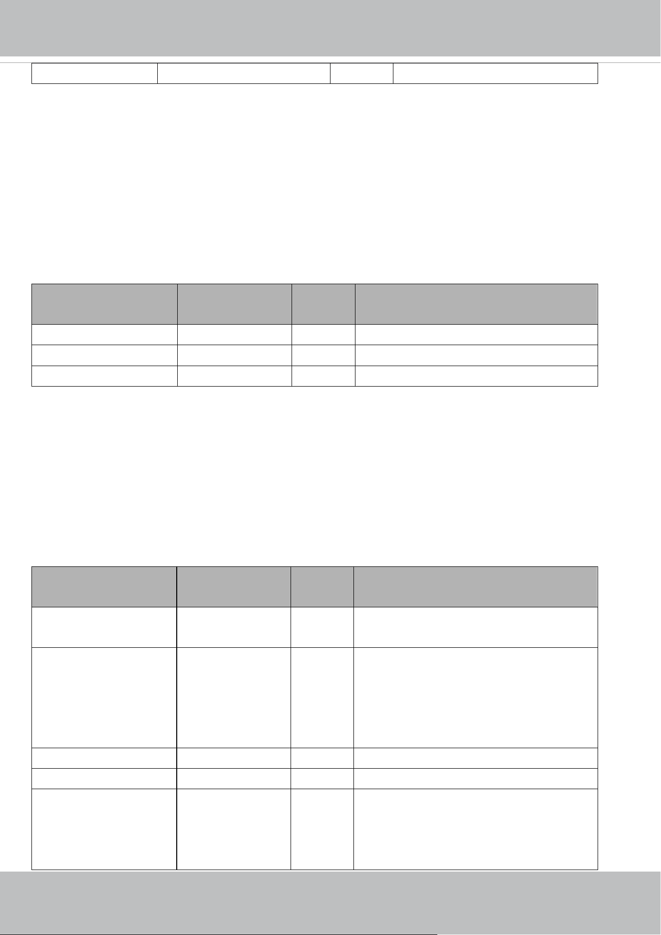
VIVOTEK
User's Manual - 201
ROI and non-ROI areas.
Group: videoin_c<0~(n-1)>_s<0~(m-1)>_h264_smartstream2_win_i<0~(k-1)>
(capability_smartstream_support=1, capability_smartstream_version>=2.0 and
capability_smartstream_mode_manual = 1)
Group: videoin_c<0~(n-1)>_s<0~(m-1)>_h265_smartstream2_win_i<0~(k-1)>
(capability_smartstream_support=1, capability_smartstream_version>=2.0 and h265 is listed in
"capability_videoin_codec" and capability_smartstream_mode_manual = 1)
n denotes the value of "capability_nvideoin",m denotes the value of " capability_nmediastream",k denotes the
value of "capability_smartstream_nwindow_manual".
NAME VALUE SECURITY
(get/set)
DESCRIPTION
enable <boolean> 4/4 Enable or disable the window.
home 0~320,0~240 4/4 Left-top corner coordinate of the window.
size 0~320x0~240 4/4 Width and height of the window
7.8.1.1 Alternative video input profiles per channel
In addition to the primary setting of video input, there can be alternative profile video input setting for each
channel which might be for different scene of light (daytime or nighttime).
Group: videoin_c<0~(n-1)>_profile_i<0~(m-1)> for n channel profucts and m profile
n denotes the value of "capability_nvideoin" and m denotes the value of "capability_nvideoinprofile"
(capability.nvideoinprofile> 0)
NAME VALUE SECURITY
(get/set)
DESCRIPTION
enable <boolean> 4/4 Enable/disable this profile setting
policy night,
schedule
4/4 The mode which the profile is applied to.
* Not support "policy=day" anymore when the
version number (httpversion) is equal or
greater than 0301a.
begintime hh:mm 4/4 Begin time of schedule mode.
endtime hh:mm 4/4 End time of schedule mode.
minexposure
<product dependent>
<1~32000>,
<5~32000>,
<1~8000>,
<5~8000>,
4/4 Minimum exposure time
1~32000 => 1s ~ 1/32000s
5~32000 => 1/5s ~ 1/32000s
1~8000 => 1s ~ 1/8000s

VIVOTEK
202 - User's Manual
etc.
* Available value is
listed in
"capability_image_c
<0~(n-1)>_exposu
re_minrange"
5~8000 => 1/5s ~ 1/8000s
etc.
* Only available when
"capability_image_c<0~(n-1)>_exposure_mi
nrange" != "-"
* Only valid when "piris_mode"=manual or
"irismode"=fixed
* Only available when
"capability_image_c<0~(n-1)>_exposure_ra
ngetype" is "twovalues".
maxexposure
<product dependent>
<1~32000>,
<5~32000>,
<1~8000>,
<5~8000>,
etc.
* Available value is
listed in
"capability_image_c
<0~(n-1)>_exposu
re_maxrange"
4/4 Maximum exposure time
1~32000 => 1s ~ 1/32000s
5~32000 => 1/5s ~ 1/32000s
1~8000 => 1s ~ 1/8000s
5~8000 => 1/5s ~ 1/8000s
etc.
* This parameter may also restrict image
frame rate from sensor due to sensor
generates a frame per exposure time. Ex: If
this is set to 1/5s ~ 1/8000s and camera takes
1/5s on the night, then sensor only outputs 5
frame/s.
* Only available when
"capability_image_c<0~(n-1)>_exposure_m
axrange" != "-"
* Only valid when "piris_mode"=manual or
"irismode"=fixed
* Only available when
"capability_image_c<0~(n-1)>_exposure_ra
ngetype" is "twovalues".
shuttervalue
<product dependent>
<1~32000>,
<5~32000>,
<1~8000>,
<5~8000>,
etc.
* Available value is
4/4 Exposure time
1~32000 => 1s ~ 1/32000s
5~32000 => 1/5s ~ 1/32000s
1~8000 => 1s ~ 1/8000s
5~8000 => 1/5s ~ 1/8000s
etc.

VIVOTEK
User's Manual - 203
listed in
"capability_image_c
<0~(n-1)>_exposu
re_maxrange"
* This parameter may also restrict image
frame rate from sensor due to sensor
generates a frame per exposure time. Ex: If
this is set to 1/5s ~ 1/8000s and camera takes
1/5s on the night, then sensor only outputs 5
frame/s.
* Only available when
"capability_image_c<0~(n-1)>_exposure_m
axrange" != "-" and
"capability_image_c<0~(n-1)>_exposure_ra
ngetype" is "onevalue".
* We support this parameter when the version
number (httpversion) is equal or greater than
0302a.
enableblc
<Not support anymore>
<boolean> 4/4 Enable backlight compensation.
* Not support this parameter anymore when
the version number (httpversion) is equal or
greater than 0301a.
* It's recommanded to use
"exposurewin_c<n>_mode" to switch on/off
BLC.
exposurelevel 0~12 4/4 Exposure level
"0,12": This range takes the concept from DC's
exposure tuning options. The definition is:
0: EV -2.0
1: EV -1.7
2: EV -1.3
3: EV -1.0
4: EV -0.7
5: EV -0.3
6: EV 0
7: EV +0.3
8: EV +0.7
9: EV +1.0
10: EV +1.3
11: EV +1.7
12: EV +2.0
*Only available when

VIVOTEK
204 - User's Manual
"capability_image_c0_exposure_mode" != 0
exposuremode
<product dependent>
auto,
shutterpriority,
irispriority,
qualitypriority,
manual,
etc
(Available options
are list in
"capability_image_c
<0~(n-1)>_exposu
re_modetype")
4/4 Select exposure mode.
"auto": Automatically adjust the Iris, Gain
and Shutter Speed to fit the exposure level.
"shutterpriority": Manually adjust with
variable Shutter Speed, and keep adjusting
Iris, Gain automatically.
"irispriority": Manually adjust with variable
Iris, and keep adjusting Gain and Shutter
speed automatically.
"qualitypriority": Automatically adjust the
Iris, Gain and Shutter Speed by VIVOTEK
quality algorithm.
"manual": Manually adjust with variable
Shutter, Iris and Gain.
* We support this parameter when the version
number (httpversion) is equal or greater than
0302a.
*Only available when
"capability_image_c0_exposure_mode" != 0
whitebalance
<product dependent>
auto,
manual,
rbgain,
widerange,
outdoor,
indoor,
sodiumauto,
etc
(Available values are
listed in
"capability_image_c
<0~(n-1)>_wbmod
e")
4/4 Modes of white balance.
"auto": Auto white balance
"rbgain": Use rgain and bgain to set white
balance manually.
"manual": 2 cases:
a. if "rbgain" is not supported, this means
keep current white balance status.
b. if "rbgain" is supported, "rgain" and
"bgain" are updated to the current values
which is got from white balance module. Then,
act as rbgain mode
"widerange": Auto Tracing White balance
(2000K to 10000K).
"outdoor": auto white balance mode
specifically for outdoor.
"indoor": auto white balance mode
specifically for indoor.
"sodiumauto": sodium vapor lamps.

VIVOTEK
User's Manual - 205
* Only available when
"capability_image_c<0~(n-1)>_wbmode" !="
-"
rgain 0~100 4/4 Manual set rgain value of gain control setting.
0: Weak <-> 100: Strong
* Only available when "rbgain" is listed in
"capability_image_c<0~(n-1)>_wbmode".
* Only valid when
"videoin_c<0~(n-1)>_whitebalance" != auto
* Normalized range.
bgain 0~100 4/4 Manual set bgain value of gain control setting.
0: Weak <-> 100: Strong
* Only available when "rbgain" is listed in
"capability_image_c<0~(n-1)>_wbmode".
* Only valid when
"videoin_c<0~(n-1)>_whitebalance" != auto
* Normalized range.
maxgain 0~100 4/4 Maximum gain value.
0: Low <-> 100: High
* Only available when
"capability_image_c<0~(n-1)>_agc_maxgain
" != "-"
* Only valid when "piris_mode"=manual or
"irismode"=fixed
* Normalized range.
* Only available when
"capability_image_c<0~(n-1)>_exposure_ra
ngetype" is "twovalues".
mingain 0~100 4/4 Minimum gain value.
0: Low <-> 100: High
* Only available when
"capability_image_c<0~(n-1)>_agc_mingain
" != "-"
* Only valid when "piris_mode"=manual or
"irismode"=fixed

VIVOTEK
206 - User's Manual
* Normalized range.
* Only available when
"capability_image_c<0~(n-1)>_exposure_ra
ngetype" is "twovalues".
gainvalue 0~100 4/4 Gain value.
0: Low <-> 100: High
* Only available when
"capability_image_c<0~(n-1)>_agc_maxgain
" != "-" and
"capability_image_c<0~(n-1)>_exposure_ra
ngetype" is "onevalue".
* Normalized range.
* We support this parameter when the version
number (httpversion) is equal or greater than
0302a.
piris_mode
<product dependent>
manual, indoor,
outdoor,-
1/4 Control P-Iris mode.
"outdoor": Auto-setting P-Iris to get best
quality, but easy to meet rolling or flicker effect
in indoor environment.
"indoor": Avoid rolling and flicker effect first.
"manual": Manual set P-Iris by
"piris_position".
"-": not support (only available when
"capability_image_c<0~(n-1)>_sensortype"
is "smartsensor")
* Only available when
"capability_image_c<0~(n-1)>_iristype"=piri
s
piris_position
<product dependent>
1~100 1/4 Manual set P-Iris.
1: Open <-> 100: Close
* Only valid when "piris_mode"=manual or
"capability_image_c<0~(n-1)>_sensortype"
is "smartsensor"
* Only available when
"capability_image_c<0~(n-1)>_iristype"=piri
s
irismode fixed, indoor, 4/4 Control DC-Iris mode.

VIVOTEK
User's Manual - 207
outdoor
<product
dependent>
"outdoor": Auto-setting DC-Iris to get best
quality, but easy to meet rolling or flicker effect
in indoor environment.
"indoor": Avoid rolling and flicker effect first.
"fixed": Open the iris to maximum.
* Only available when
"capability_image_c<0~(n-1)>_iristype"=dci
ris
wdrpro_mode
<product dependent>
<boolean> 4/4 Enable WDR pro
* Only available when
"capability_image_c<0~(n-1)>_wdrpro_mod
e" > 0
wdrpro_strength
<product dependent>
1~100 4/4 The strength of WDR Pro.
The bigger value means the stronger strength
of WDR Pro.
* Only available when
"capability_image_c<0~(n-1)>_wdrpro_stren
gth" is 1
wdrc_mode
<product dependent>
<boolean> 4/4 Enable WDR enhanced.
* Only available when
"capability_image_c<0~(n-1)>_wdrc_mode"
is 1
wdrc_strength
<product dependent>
1~100 4/4 The strength of WDR enhanced.
The bigger value means the stronger strength
of WDR enhanced.
* Only available when
"capability_image_c<0~(n-1)>_wdrc_mode"
is 1
aespeed_mode
<product dependent>
<boolean> 4/4 Turning AE converge speed on or off.
0: off
1: on
* Only available when
"capability_image_c<0~(n-1)>_aespeed" is 1
aespeed_speedlevel
<product dependent>
1~100 4/4 The speed level of AE converge speed.
1~20: level 1
21~40: level 2
41~60: level 3
61~80: level 4

VIVOTEK
208 - User's Manual
81~100: level 5
Level 1~4(low ~ high)
The higher speed level meas shorter AE
converged time during AE executing.
* Only available when
"capability_image_c<0~(n-1)>_aespeed" is 1
aespeed_sensitivity
<product dependent>
1~100 4/4 The sensitivity of AE converge speed.
1~20: level 1
21~40: level 2
41~60: level 3
61~80: level 4
81~100: level 5
Level 1~4(low ~ high)
The higher sensitivity level meas that it is easy
to be trigger while scene changed.
* Only available when
"capability_image_c<0~(n-1)>_aespeed" is 1
and
"capability_image_c<0~(n-1)>_aespeedsupp
ortsensitivity" is 1.
flickerless
<product dependent>
<boolean> 4/4 Turn on(1) or turn off(0) the flickerless mode
* Only available when
"capability_image_c<0~(n-1)>_flickerless" is
1
7.9Time Shift settings
Group: timeshift for n channel profucts and m stream
n denotes the value of "capability_nvideoin", m denotes the value of "capability_nmediastream"
(capability.timeshift > 0)
NAME VALUE SECURITY
(get/set)
DESCRIPTION
enable <boolean> 4/4 Enable time shift streaming.
c<0~(n-1)>_s<0~(m-1)
>_allow
<boolean> 4/4 Enable time shift streaming for specific
stream.

VIVOTEK
User's Manual - 209
7.10 IR cut control
Group: ircutcontrol
(capability.nvideoinprofile> 0 and capability_daynight_c<0~(n-1)>_support > 0)
n denotes the value of "capability_nvideoin"
NAME VALUE SECURITY
(get/set)
DESCRIPTION
mode auto,
day,
night,
di,
schedule…etc
* Available values
are listed in
"capability_daynight
_c<0~(n-1)>_mod
e"
<product
dependent>
6/6 Set IR cut control mode
sir
<product dependent>
<boolean> 6/6 Enable/disable Smart IR
* Only available when
"capability_daynight_c<0~"capability_nvideoi
n"-1>_smartir" is 1
daymodebegintime 00:00~23:59 6/6 Day mode begin time
daymodeendtime 00:00~23:59 6/6 Day mod end time
disableirled <boolean> 6/6 Enable/disable built-in IR led
(capability_daynight_c<0~"capability_nvideoi
n"-1>_builtinir > 0)
enableextled <boolean> 1/6 Enable/disable external IR led
(capability_daynight_c<0~"capability_nvideoi
n"-1>_externalir > 0)
enablewled <boolean> 6/6 Enable/disable built-in White led
(capability_daynight_c<0~"capability_nvideoi
n"-1>_builtinwled > 0)
extledmode do, irring
* Available values
are listed in
"capability_daynight
_c<0~(n-1)>_extle
d_interface"
6/6 Turn on an external IR led which is mounted do
(digital output) device or is a IR ring device.
* Only available when
"capability_daynight_c<0~"capability_nvideoi
n"-1>_externalir" is 1.
* Only valid when "ircutcontrol_enableextled"
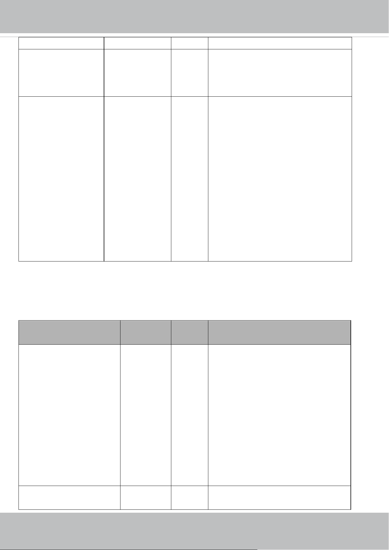
VIVOTEK
210 - User's Manual
is 1.
bwmode <boolean> 6/6 Switch to B/W in night mode if enabled.
* Only available when
"capability_daynight_c<0~(n-1)>_
blackwhitemode" is 1.
sensitivity low,normal,high,1~
100
6/6 Sensitivity of day/night control.
There are two value format:
"low,normal,high": if
capability_daynight_c<0~(n-1)>_ircutsensiti
vity_type=options
"1~100": if
capability_daynight_c<0~(n-1)>_ircutsensiti
vity_type=normalize
* Only available when
"capability_daynight_c<0~(n-1)>
_ircutsensitivity_type" is not "-".
7.11 Image setting per channel
Group: image_c<0~(n-1)> for n channel profucts and m profile
n denotes the value of "capability_nvideoin" and m denotes the value of "capability_nvideoinprofile"
NAME VALUE SECURITY
(get/set)
DESCRIPTION
brightness
<Not recommended to use this>
-5~5,100 4/4 -5: Darker <-> 5: Bright
100: Use " image_c<n>_brightnesspercent"
* Only available when bit 0 of
"capability_image_c<0~(n-1)>_basicsetting"
is 1
* We replace "brightness" with
"brightnesspercent".
* This parameter will not be used after the
version number (httpversion) is equal or
greater than 0400a.
contrast
<Not recommended to use this>
-5~5,100 4/4 -5: Less contrast <-> 5: More contrast
100: Use "

VIVOTEK
User's Manual - 211
image_c<0~(n-1)>_contrastpercent"
* Only available when bit 1 of
"capability_image_c<0~(n-1)>_basicsetting"
is 1.
* We replace "contrast" with "contrastpercent
".
* This parameter will not be used after the
version number (httpversion) is equal or
greater than 0400a.
saturation
<Not recommended to use this>
-5~5,100 4/4 -5: Less saturation <-> 5: More saturation
100: Use " image_c<n>_saturationpercent"
* Only available when bit 2 of
"capability_image_c<0~(n-1)>_basicsetting"
is 1.
* We replace "saturation" with
"saturationpercent".
* This parameter will not be used after the
version number (httpversion) is equal or
greater than 0400a.
sharpness
<Not recommended to use this>
-3~3,100 4/4 -3: Softer <-> 3: Sharper
100: Use "
image_c<0~(n-1)>_sharpnesspercent"
* Only available when bit 3 of
"capability_image_c<0~(n-1)>_basicsetting"
is 1.
* We replace "sharpness" with
"sharpnesspercent".
* This parameter will not be used after the
version number (httpversion) is equal or
greater than 0400a.
brightnesspercent 0~100 4/4 Set brightness in the normalized range.
0: Darker <-> 100: Bright
* Only available when bit 0 of

VIVOTEK
212 - User's Manual
"capability_image_c<0~(n-1)>_basicsetting"
is 1.
contrastpercent 0~100 4/4 Set contrast in the normalized range.
0: Less contrast <-> 100: More contrast
* Only available when bit 1 of
"capability_image_c<0~(n-1)>_basicsetting"
is 1
saturationpercent 0~100 4/4 Set saturation in the normalized range.
0: Less saturation <-> 100: More saturation
* Only available when bit 2 of
"capability_image_c<0~(n-1)>_basicsetting"
is 1.
sharpnesspercent 0~100 4/4 Set sharpness in the normalized range.
0: Softer <-> 100: Sharper
* Only available when bit 3 of
"capability_image_c<0~(n-1)>_basicsetting"
is 1
gammacurve
<product dependent>
0~100 4/4 0: Fine-turned gamma curve by Vivotek.
1: Gamma value = 0.01
2: Gamma value = 0.02
3: Gamma value = 0.03
...
100: Gamma value = 1
* Note: Although we set gamma value to 100
level, but not all gamma values are valid.
Internal module will take the closest valid one.
For example, 1~45 may all be mapped to
gamma value = 0.45, etc.
* Only available when
"capability_image_c<0~(n-1)>_gammacurv
e" is 1
lowlightmode
<product dependent>
<boolean> 4/4 Enable/disable low light mode.
* Only available when
"capability_image_c<0~(n-1)>_lowlightmod
e" is 1
dnr_mode <boolean> 4/4 3D noise reduction.

VIVOTEK
User's Manual - 213
<product dependent> 0:disable
1:enable
* Only available when
"capability_image_c<0~(n-1)>_dnr" is 1
dnr_strength
<product dependent>
1~100 4/4 Strength of 3DNR
* Only available when
"capability_image_c<0~(n-1)>_dnr" is 1
defog_mode
<product dependent>
<boolean> 4/4 Enable/disable defog mode.
0:disable
1:enable
* Only available when
"capability_image_c<0~(n-1)>_defog_mode
" is 1
defog_strength
<product dependent>
1~100 4/4 Strength of defog
* Only available when
"capability_image_c<0~(n-1)>_defog_mode
" is 1
eis_mode
<product dependent>
<boolean> 4/4 Electronic image stabilizer
0:disable
1:enable
* Only available when 'eis' is listed in
"capability_image_c<0~(n-1)>_is_mode".
eis_strength
<product dependent>
1~100 4/4 Strength of electronic image stabilizer
* Only available when 'eis' is listed in
"capability_image_c<0~(n-1)>_is_mode".
dis_mode
<product dependent>
<boolean> 4/4 Digital image stabilizer
0:disable
1:enable
* Only available when 'dis' is listed in
"capability_image_c<0~(n-1)>_is_mode".
dis_strength
<product dependent>
1~100 4/4 Strength of digital image stabilizer
* Only available when 'dis' is listed in
"capability_image_c<0~(n-1)>_is_mode".
scene_mode
<product dependent>
Available value
is listed in
"capability_im
age_c<0~(n-1
)>_scenemod
e_supporttype
"
4/4 Value of scene mode
* Only available when
"capability_image_c<0~(n-1)>_scenemode_
support" is 1

VIVOTEK
214 - User's Manual
<product
dependent>
restoreatwb <positive
integer>
4/4 Restore of adjusting white balance of image
according to mode settings
freeze
<product dependent>
<boolean> 4/4 Enable/disable Image freeze while patrolling.
0: disable
1: enable
* Only available when
"capability_image_c<0~(n-1)>_freeze" is 1
deinterlace_enable <boolean> 4/4 Enable/disable deinterlace function.
0: disable
1: enable
* Only available when
"capability_image_c<0~(n-1)>_deinterlace_
support" is 1.
deinterlace_mode spatial,blend 4/4 Users can choose between two different
deinterlacing techniques:
Spatical mode provides the best image quality,
while Blend mode provides better image
quality (than not using the deinterlace
function at all).
* Only available when
"capability_image_c<0~(n-1)>_deinterlace_
support" is 1.
xoffset 0~100 4/4 Adjusting the image to proper position
horizontally.
* Only available when the bit 4 of
capability_image_c<0~(n-1)>_basicsetting is
1.
yoffset 0~100 4/4 Adjusting the image to proper position
vertically.
* Only available when the bit 5 of
capability_image_c<0~(n-1)>_basicsetting is
1.
lens_alignment 0~100 4/4 Stitch the sensors together into focused
position.
* Only available when
"capability_image_c<0~(n-1)>_lens_alignm
ent" is 1.

VIVOTEK
User's Manual - 215
lens_ldc_mode <boolean> 4/4 Enable/disable lens distortion correction.
* Only available when
"capability_image_c<0~(n-1)>_lens_ldc_sup
port" is 1.
palette_mode Available value
is listed in
"capability_im
age_c<0~(n-1
)>_palette_m
ode"
4/4 Set color palette option.
* Only available when
"capability_image_c<0~(n-1)>_palette_supp
ort" is 1.
* Not support "policy=day" anymore when the
version number (httpversion) is equal or
greater than 0310a.
profile_i<0~(m-1)>_enable <boolean> 4/4 Enable/disable this profile setting
profile_i<0~(m-1)>_policy night,
schedule
4/4 The mode which the profile is applied to.
* Not support "policy=day" anymore when the
version number (httpversion) is equal or
greater than 0301a.
profile_i<0~(m-1)>_begintime hh:mm 4/4 Begin time of schedule mode.
profile_i<0~(m-1)>_endtime hh:mm 4/4 End time of schedule mode.
profile_i<0~(m-1)>_brightness
<Not recommended to use this>
-5~5,100 4/4 -5: Darker <-> 5: Bright
100: Use "
image_c<0~(n-1)>_brightnesspercent"
* Only available when bit 0 of
"capability_image_c<0~(n-1)>_basicsetting"
is 1
* We replace "profile_i0_brightness" with
"profile_i0_brightnesspercent".
* This parameter will not be used after the
version number (httpversion) is equal or
greater than 0400a.
profile_i<0~(m-1)>_contrast
<Not recommended to use this>
-5~5,100 4/4 -5: Less contrast <-> 5: More contrast
100: Use "
image_c<0~(n-1)>_contrastpercent"
* Only available when bit 1 of
"capability_image_c<0~(n-1)>_basicsetting"
is 1.

VIVOTEK
216 - User's Manual
* We replace "profile_i0_contrast" with
"profile_i0_contrastpercent ".
* This parameter will not be used after the
version number (httpversion) is equal or
greater than 0400a.
profile_i<0~(m-1)>_saturation
<Not recommended to use this>
-5~5,100 4/4 -5: Less saturation <-> 5: More saturation
100: Use "
image_c<0~(n-1)>_saturationpercent"
* Only available when bit 2 of
"capability_image_c<0~(n-1)>_basicsetting"
is 1.
* We replace "profile_i0_saturation" with
"profile_i0_saturationpercent".
* This parameter will not be used after the
version number (httpversion) is equal or
greater than 0400a.
profile_i<0~(m-1)>_sharpness
<Not recommended to use this>
-3~3,100 4/4 -5: Less saturation <-> 5: More saturation
100: Use "
image_c<0~(n-1)>_saturationpercent"
* Only available when bit 2 of
"capability_image_c<0~(n-1)>_basicsetting"
is 1.
* We replace "profile_i0_saturation" with
"profile_i0_saturationpercent".
* This parameter will not be used after the
version number (httpversion) is equal or
greater than 0400a.
profile_i<0~(m-1)>_brightness
percent
0~100 4/4 Set brightness in the normalized range.
0: Darker <-> 100: Bright
* Only available when bit 0 of
"capability_image_c<0~(n-1)>_basicsetting"
is 1.
profile_i<0~(m-1)>_contrastpe
rcent
0~100 4/4 Set contrast in the normalized range.
0: Less contrast <-> 100: More contrast

VIVOTEK
User's Manual - 217
* Only available when bit 1 of
"capability_image_c<0~(n-1)>_basicsetting"
is 1
profile_i<0~(m-1)>_saturation
percent
0~100 4/4 Set saturation in the normalized range.
0: Less saturation <-> 100: More saturation
* Only available when bit 2 of
"capability_image_c<0~(n-1)>_basicsetting"
is 1.
profile_i<0~(m-1)>_sharpness
percent
0~100 4/4 Set sharpness in the normalized range.
0: Softer <-> 100: Sharper
* Only available when bit 3 of
"capability_image_c<0~(n-1)>_basicsetting"
is 1
profile_i<0~(m-1)>_gammacur
ve
0~100 4/4 0: Fine-turned gamma curve by Vivotek.
1: Gamma value = 0.01
2: Gamma value = 0.02
3: Gamma value = 0.03
...
100: Gamma value = 1
* Note: Although we set gamma value to 100
level, but not all gamma values are valid.
Internal module will take the closest valid one.
For example, 1~45 may all be mapped to
gamma value = 0.45, etc.
* Only available when
"capability_image_c<0~(n-1)>_gammacurve
" is 1
profile_i<0~(m-1)>_lowlightm
ode
<product dependent>
<boolean> 4/4 Enable/disable low light mode.
* Only available when
"capability_image_c<0~(n-1)>_lowlightmod
e" is 1
profile_i<0~(m-1)>_dnr_mode
<product dependent>
<boolean> 4/4 3D noise reduction.
0:disable
1:enable
* Only available when
"capability_image_c<0~(n-1)>_dnr" is 1

VIVOTEK
218 - User's Manual
profile_i<0~(m-1)>_dnr_stren
gth
<product dependent>
1~100 4/4 Strength of 3DNR
* Only available when
"capability_image_c<0~(n-1)>_dnr" is 1
profile_i<0~(m-1)>_defog_mo
de
<product dependent>
<boolean> 4/4 Enable/disable defog mode.
0:disable
1:enable
* Only available when
"capability_image_c<0~(n-1)>_defog_mode
" is 1
profile_i<0~(m-1)>_defog_str
ength
<product dependent>
1~100 4/4 Strength of defog
* Only available when
"capability_image_c<0~(n-1)>_defog_mode
" is 1
profile_i<0~(m-1)>_eis_mode
<product dependent>
<boolean> 4/4 Electronic image stabilizer
0:disable
1:enable
* Only available when 'eis' is listed in
"capability_image_c<0~(n-1)>_is_mode".
profile_i<0~(m-1)>_eis_streng
th
<product dependent>
1~100 4/4 Strength of electronic image stabilizer
* Only available when 'eis' is listed in
"capability_image_c<0~(n-1)>_is_mode".
profile_i<0~(m-1)>_dis_mode
<product dependent>
<boolean> 4/4 Digital image stabilizer
0:disable
1:enable
* Only available when 'dis' is listed in
"capability_image_c<0~(n-1)>_is_mode".
profile_i<0~(m-1)>_dis_streng
th
<product dependent>
1~100 4/4 Strength of digital image stabilizer
* Only available when 'dis' is listed in
"capability_image_c<0~(n-1)>_is_mode".

VIVOTEK
User's Manual - 219
7.12 Exposure window setting per channel
Group: exposurewin_c<0~(n-1)> for n channel profucts
n denotes the value of "capability_nvideoin"
(Only available when "capability_image_c<0~(n-1)>_exposure_mode"=1)
NAME VALUE SECURITY
(get/set)
DESCRIPTION
mode auto, custom,blc,hlc
* Available values are listed in
"capability_image_c<0~(n-1)>_
exposure_winmode"
4/4 "auto": Use full image view as the only
exposure window.
"custom": Use custom windows.
"blc": Use BLC(Back Light Compensation),
and the only exposure window is located at the
center of view.
"hlc": Use HLC (High Light Compensation),
and to perform the masking of bright light
area.
Group: exposurewin_c<0~(n-1)>_win_i<0~(k-1)>
n denotes the value of "capability_nvideoin",
k denotes the value of "capability_image_c<0~(n-1)>_exposure_winnum".
(Only available when "capability_image_c<0~(n-1)>_exposure_mode"=1 and when custom is listed in
"capability_image_c<0~(n-1)>_exposure_winmode" and valid when "exposurewin_c<0~(n-1)>_mode"=custom
or "exposurewin_c<0~(n-1)>_mode"=hlc)
NAME VALUE SECURITY
(get/set)
DESCRIPTION
enable <boolean> 4/4 Enable or disable the window.
policy 0~1 4/4 0: Indicate exclusive.
1: Indicate inclusive.
* Only available when exclusive is listed in
"capability_image_c<0~(n-1)>_exposure_wi
ntype".
home <0~320,0~240> 4/4 Left-top corner coordinate of the window.
* Only available when qvga is listed in
"capability_image_c<0~(n-1)>_exposure_wi
ndomain".
size <0~320x0~240> 4/4 Width and height of the window.
* Only available when qvga is listed in

VIVOTEK
220 - User's Manual
"capability_image_c<0~(n-1)>_exposure_wi
ndomain".
homepx <0~W,0~H>
W: 0~ The current image width -1
H: 0~ The current image height -1
4/4 Left-top corner coordinate of the window.
* Only available when px is listed in
"capability_image_c<0~(n-1)>_exposure_wi
ndomain".
sizepx <0~Wx0~ H>
W: 0~ The current image width -1
H: 0~ The current image height -1
4/4 Width and height of the window.
* Only available when px is listed in
"capability_image_c<0~(n-1)>_exposure_wi
ndomain".
homestd <0~9999,0~9999> 4/4 Left-top corner coordinate of the window.
* Only available when std is listed in
"capability_image_c<0~(n-1)>_exposure_wi
ndomain".
sizestd <0~9999x0~9999> 4/4 Width and height of the window.
* Only available when std is listed in
"capability_image_c<0~(n-1)>_exposure_wi
ndomain".
Group: exposurewin_c<0~(n-1)>_profile_i<0~(m-1)> for n channel profuct and m profile,
n denotes the value of "capability_nvideoin", m denotes the value of "capability_nvideoinprofile",
(Only available when "capability_image_c<0~(n-1)>_exposure_mode"=1)
NAME VALUE SECURITY
(get/set)
DESCRIPTION
mode auto, custom,blc,hlc
* Available values are listed in
"capability_image_c<0~(n-1)>_
exposure_winmode"
4/4 The mode indicates how to decide the
exposure.
"auto": Use full view as the only one exposure
window.
"custom": Use inclusive and exclusive
window.
"blc": Use BLC(Back Light Compensation),
and the only exposure window is located at the
center of view.
"hlc": Use HLC (High Light Compensation),
and to perform the masking of bright light
area.

VIVOTEK
User's Manual - 221
Group: exposurewin_c<0~(n-1)>_profile_i<0~(m-1)>_win_i<0~(k-1)> for m profile and n channel
product,
n denotes the value of "capability_nvideoin", m denotes the value of "capability_nvideoinprofile",
k denotes the value of "capability_image_c<0~(n-1)>_exposure_winnum".
(Only available when "capability_image_c<0~(n-1)>_exposure_mode"=1 and when custom is listed in
"capability_image_c<0~(n-1)>_exposure_winmode" and valid when "exposurewin_c<0~(n-1)>_mode"=custom
or "exposurewin_c<0~(n-1)>_mode"=hlc)
NAME VALUE SECURITY
(get/set)
DESCRIPTION
enable <boolean> 4/4 Enable or disable the window.
policy 0~1 4/4 0: Indicate exclusive.
1: Indicate inclusive.
* Only available when exclusive is listed in
"capability_image_c<0~(n-1)>_exposure_
wintype".
home <0~320,0~240> 4/4 Left-top corner coordinate of the window.
* Only available when qvga is listed in
"capability_image_c<0~(n-1)>_exposure_
windomain".
size <0~320x0~240> 4/4 Width and height of the window.
* Only available when qvga is listed in
"capability_image_c<0~(n-1)>_exposure_
windomain".
homepx <0~W,0~H>
W: 0~ The current image width -1
H: 0~ The current image height -1
4/4 Left-top corner coordinate of the window.
* Only available when px is listed in
"capability_image_c<0~(n-1)>_exposure_
windomain".
sizepx <0~Wx0~ H>
W: 0~ The current image width -1
H: 0~ The current image height -1
4/4 Width and height of the window.
* Only available when px is listed in
"capability_image_c<0~(n-1)>_exposure_
windomain".
homestd <0~9999,0~9999> 4/4 Left-top corner coordinate of the window.
* Only available when std is listed in
"capability_image_c<0~(n-1)>_exposure_

VIVOTEK
222 - User's Manual
windomain".
sizestd <0~9999x0~9999> 4/4 Width and height of the window.
* Only available when std is listed in
"capability_image_c<0~(n-1)>_exposure_
windomain".
7.13 Audio input per channel
Group: audioin_c<0~(n-1)> for n channel products
(capability.naudioin>0)
n denotes the value of "capability_nvideoin"
NAME VALUE SECURITY
(get/set)
DESCRIPTION
source
<Not recommended to use
this>
micin, linein
<product
dependent>
4/4 micin => use built-in microphone input.
linein => use external microphone input.
* Reserved for compatibility, and suggest don't
use this since the version number
(httpversion) is equal or greater than 0301a.
* We replace "source" with "input". More
details, please refer the parameter description
of "input".
input intmic, extmic
<product
dependent>
4/4 intmic: Internal (built-in) microphone.
(Only available when capability_audio_intmic
= 1)
extmic: External microphone input.
(Only available when capability_audio_extmic
=1)
* Note: If physical microphone switch is
showed on product, this value is updated
during booting to fit switch status.
volume_internal 0~100 4/4 Volume when take internal microphone as
input source.
0: Minimum
100: Maximum
* Only available when the channel supports
internal microphone (The related bit of
"capability_audio_intmic" is equal to 1).

VIVOTEK
User's Manual - 223
volume_external 0~100 4/4 Volume when take external microphone as
input source.
0: Minimum
100: Maximum
* Only available when the channel supports
external microphone (The related bit of
"capability_audio_extmic" is equal to 1).
mute 0, 1 1/4 0: Mute off
1: Mute on
gain
<Not recommended to use
this>
0~100 4/4 Gain of input.
(audioin_c<0~(n-1)>_source = linein)
* Reserved for compatibility, and suggest don't
use this since the version number
(httpversion) is equal or greater than 0301a.
* We replace "gain" with "volume_internal"
and "volume_external". More details, please
refer the parameter description of
"volume_internal" and "volume_external".
boostmic
<Not recommended to use
this>
0~100 4/4 Enable microphone boost.
Gain of input.
(audioin_c<0~(n-1)>_source = micin)
* Reserved for compatibility, and suggest don't
use this since the version number
(httpversion) is equal or greater than 0301a.
* We replace "boostmic" with
"volume_internal" and "volume_external".
More details, please refer the parameter
description of "volume_internal" and
"volume_external".
s0_codectype aac4, gamr, g711,
g726
(Available codec are
listed in
"capability_audioin_
codec")
4/4 Set audio codec type for input.
aac4: Advanced Audio Coding (AAC)
gamr: Adaptive Multi-Rate (AMR)
g711: G.711
g726: G.726
s0_aac4_bitrate 16000,
32000,
4/4 Set AAC4 bitrate in bps.

VIVOTEK
224 - User's Manual
48000,
64000,
96000,
128000
* Only available if AAC is supported.
s0_gamr_bitrate 4750,
5150,
5900,
6700,
7400,
7950,
10200,
12200
4/4 AMR encoded bitrate in bps.
* Only available if AMR is supported.
s0_g711_mode pcmu,
pcma
4/4 Set G.711 companding algorithm.
pcmu: µ-law algorithm
pcma: A-law algorithm
* Only available if G.711 is supported.
s0_g726_bitrate 16000,
24000,
32000,
40000
4/4 Set G.726 encoded bitrate in bps.
* Only available if G.726 is supported
.
s0_g726_bitstreampackin
gmode
little, big 4/4 Set G.726 bit streaming packing mode.
little: Little-endian bitstream format.
big: Big-endian bitstream format.
* Only available if G.726 is supported.
s0_g726_vlcmode 0, 1 4/4 Enable vlcmode for G.726.
0: Standard mode.
1: Solve compatibility problem with VLC
player.
* Only available if G.726 is supported.
aec_enable <boolean> 4/4 Enable acoustic echo cancellation.
* Only available when
"capability_audio_aecmode" is "manual".
* We support this parameter when the version
number (httpversion) is equal or greater than
0306b.
alarm_enable <boolean> 4/4 Enable audio detection
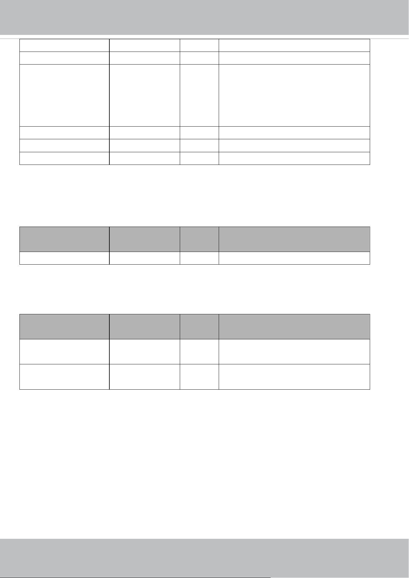
VIVOTEK
User's Manual - 225
alarm_level 1~100 4/4 Audio detection alarm level
profile_i0_enable <boolean> 4/4 Enable/disable this profile setting
profile_i0_policy night,
schedule
4/4 The mode which the profile is applied to.
* Not support "policy=day" anymore when the
version number (httpversion) is equal or
greater than 0301a.
profile_i0_begintime hh:mm 4/4 Begin time of schedule mode.
profile_i0_endtime hh:mm 4/4 End time of schedule mode.
profile_i0_alarm_level 1~100 4/4 Audio detection alarm level
7.14 Audio out per channel
Group: audioout_c<0~(n-1)> for n channel products
(capability_audio_audioclip=1)
n denotes the value of "capability_nvideoin"
NAME VALUE SECURITY
(get/set)
DESCRIPTION
volume 0~100 4/4 Adjusting audio volume
7.15 Play an audio clip
Group: audioclip_i<0~1>
(capability_audio_audioclip=1)
NAME VALUE SECURITY
(get/set)
DESCRIPTION
name string[40] 1/4 Specify the audio clip name that can be played
when an event occurs.
size 0,<positive
integer>
1/4 The size of audio clip.
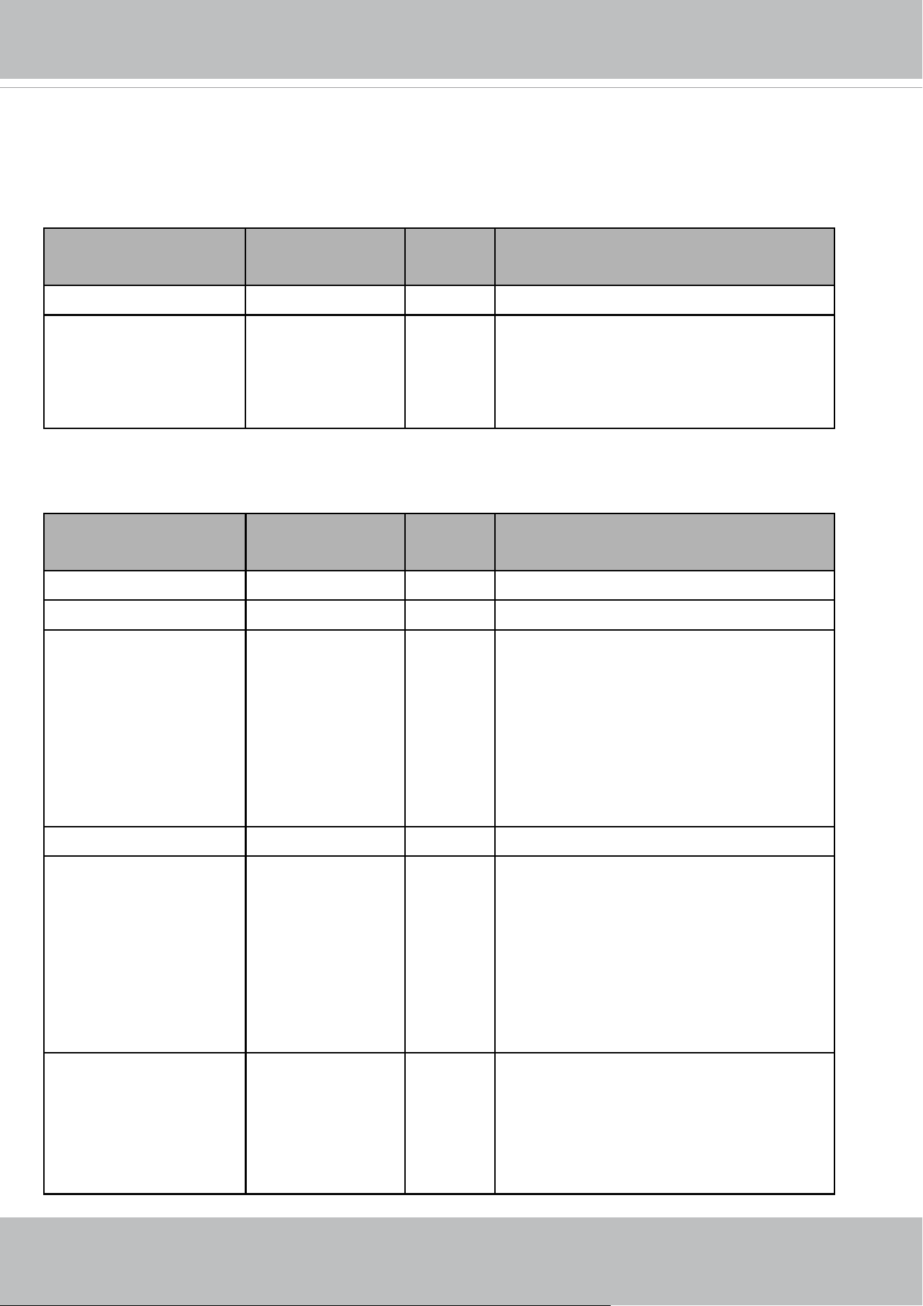
VIVOTEK
226 - User's Manual
7.16 Motion detection settings
Group: motion_c<0~(n-1)> for n channel products
n denotes the value of "capability_nvideoin"
NAME VALUE SECURITY
(get/set)
DESCRIPTION
enable <boolean> 4/4 Enable motion detection.
win_sensitivity 0 ~ 100 4/4 Sensitivity of all motion detection windows.
* The value "0" is reserved for compatibility
and will not be used after the version number
(httpversion) is equal or greater than 0400a.
Group: motion_c<0~(n-1)>_win_i<0~(k-1)>
n denotes the value of "capability_nvideoin", k denotes the value of "capability_nmotion".
NAME VALUE SECURITY
(get/set)
DESCRIPTION
enable <boolean> 4/4 Enable motion detection window.
name string[14] 4/4 Name of motion window.
polygonstd 0 ~ 9999,0 ~ 9999,
0 ~ 9999,0 ~ 9999,
0 ~ 9999,0 ~ 9999,
0 ~ 9999,0 ~ 9999
4/4 Coordinate of polygon window position.
(4 points: x0,y0,x1,y1,x2,y2,x3,y3)
* Only available when
"capability_motion_wintype" = polygon.
* Only available when std is listed in
"capability_motion_windomain"
objsize 1 ~ 100 4/4 Percent of motion detection window.
sensitivity
<Not recommended to use
this>
0 ~ 100 4/4 Sensitivity of motion detection window.
* We replace "sensitivity" with
"win_sensitivity".
* This parameter will not be used after the
version number (httpversion) is equal or
greater than 0400a.
polygonpx
<Not recommended to use
this>
0 ~ W,0 ~ H, 0 ~
W,0 ~ H, 0 ~ W,0 ~
H, 0 ~ W,0 ~ H
W: 0~ The current
image width -1
4/4 Coordinate of polygon window position.
(4 points: x0,y0,x1,y1,x2,y2,x3,y3)
* Only available when
"capability_motion_wintype" = polygon.

VIVOTEK
User's Manual - 227
H: 0~ The current
image height -1
* Only available when px is listed in
"capability_motion_windomain".
* It's recommended to use polygonsd
* This parameter will not be used after the
version number (httpversion) is equal or
greater than 0400a.
polygon
<Not recommended to use
this>
0 ~ 320,0 ~ 240, 0
~ 320,0 ~ 240, 0 ~
320,0 ~ 240, 0 ~
320,0 ~ 240
4/4 Coordinate of polygon window position.
(4 points: x0,y0,x1,y1,x2,y2,x3,y3)
* Only available when
"capability_motion_wintype" = polygon.
* Only available when qvga is listed in
"capability_motion_windomain".
* It's recommended to use polygonsd
* This parameter will not be used after the
version number (httpversion) is equal or
greater than 0400a.
left
<Not recommended to use
this>
0 ~ 320 4/4 Left coordinate of window position.
* Only available when
"capability_motion_wintype" = rectangle.
* Only available when qvga is listed in
"capability_motion_windomain".
* It's recommended to use polygonsd
* This parameter will not be used after the
version number (httpversion) is equal or
greater than 0400a.
top
<Not recommended to use
this>
0 ~ 240 4/4 Top coordinate of window position.
* Only available when
"capability_motion_wintype" = rectangle.
* Only available when qvga is listed in
"capability_motion_windomain".
* It's recommended to use polygonsd
* This parameter will not be used after the
version number (httpversion) is equal or
VIVOTEK
228 - User's Manual
greater than 0400a.
width
<Not recommended to use
this>
0 ~ 320 4/4 Width of motion detection window.
* Only available when
"capability_motion_wintype" = rectangle.
* Only available when qvga is listed in
"capability_motion_windomain".
* It's recommended to use polygonsd
* This parameter will not be used after the
version number (httpversion) is equal or
greater than 0400a.
height
<Not recommended to use
this>
0 ~ 240 4/4 Height of motion detection window.
* Only available when
"capability_motion_wintype" = rectangle.
* Only available when qvga is listed in
"capability_motion_windomain".
* It's recommended to use polygonsd
* This parameter will not be used after the
version number (httpversion) is equal or
greater than 0400a.
Group: motion_c<0~(n-1)>_profile_i<0~(m-1)> for m profile and n channel product,
n denotes the value of "capability_nvideoin", m denotes the vaule of " capability_nmotionprofile ",
(capability_nmotionprofile > 0)
NAME VALUE SECURITY
(get/set)
DESCRIPTION
enable <boolean> 4/4 Enable profile 1 ~ (m-1).
policy night,
schedule
4/4 The mode which the profile is applied to.
* Not support "policy=day" anymore when the
version number (httpversion) is equal or
greater than 0301a.
begintime hh:mm 4/4 Begin time of schedule mode.
endtime hh:mm 4/4 End time of schedule mode.
win_sensitivity 0 ~ 100 4/4 Sensitivity of all motion detection windows.
* The value "0" is reserved for compatibility
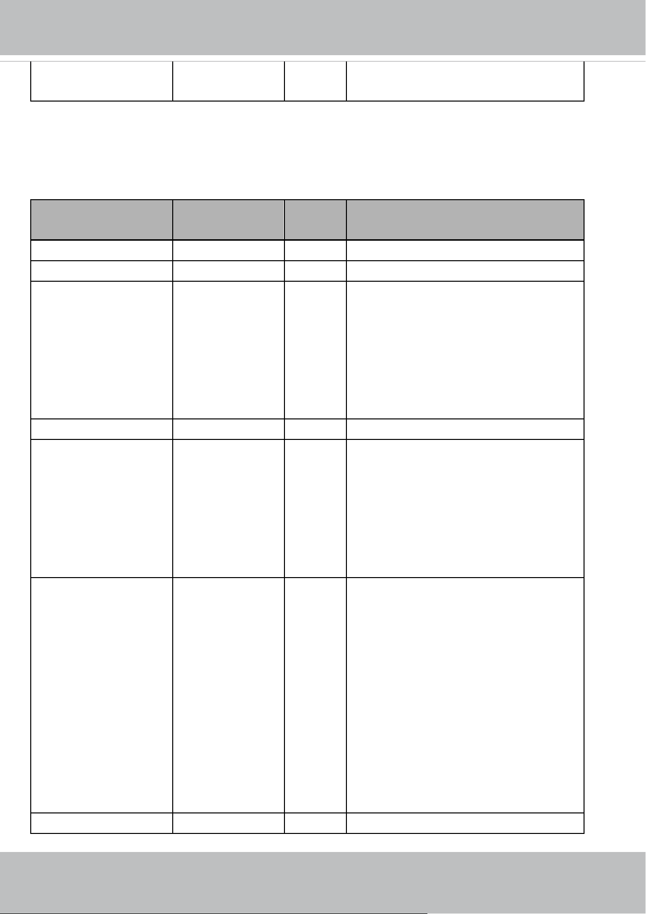
VIVOTEK
User's Manual - 229
and will not be used after the version number
(httpversion) is equal or greater than 0400a.
Group: motion_c<0~(n-1)>_profile_i<0~(m-1)>_win_i<0~(k-1)> for m profile and n channel product,
n denotes the value of "capability_nvideoin", m denotes the vaule of "capability_nmotionprofile",
k denotes the value of "capability_nmotion".
NAME VALUE SECURITY
(get/set)
DESCRIPTION
enable <boolean> 4/4 Enable motion detection window.
name string[14] 4/4 Name of motion window.
polygonstd 0 ~ 9999,0 ~ 9999,
0 ~ 9999,0 ~ 9999,
0 ~ 9999,0 ~ 9999,
0 ~ 9999,0 ~ 9999
4/4 Coordinate of polygon window position.
(4 points: x0,y0,x1,y1,x2,y2,x3,y3)
* Only available when
"capability_motion_wintype" = polygon.
* Only available when std is listed in
"capability_motion_windomain
objsize 1 ~ 100 4/4 Percent of motion detection window.
sensitivity
<Not recommended to use
this>
0 ~ 100 4/4 Sensitivity of motion detection window.
* We replace "sensitivity" with
"win_sensitivity".
* This parameter will not be used after the
version number (httpversion) is equal or
greater than 0400a.
polygonpx
<Not recommended to use
this>
0 ~ W,0 ~ H, 0 ~
W,0 ~ H, 0 ~ W,0 ~
H, 0 ~ W,0 ~ H
W: 0~ The current
image width -1
H: 0~ The current
image height -1
4/4 Coordinate of polygon window position.
(4 points: x0,y0,x1,y1,x2,y2,x3,y3)
* Only available when
"capability_motion_wintype" = polygon.
* Only available when px is listed in
"capability_motion_windomain".
* It's recommended to use polygonsd
* This parameter will not be used after the
version number (httpversion) is equal or
greater than 0400a.
polygon 0 ~ 320,0 ~ 240, 0 4/4 Coordinate of polygon window position.

VIVOTEK
230 - User's Manual
<Not recommended to use
this>
~ 320,0 ~ 240, 0 ~
320,0 ~ 240, 0 ~
320,0 ~ 240
(4 points: x0,y0,x1,y1,x2,y2,x3,y3)
* Only available when
"capability_motion_wintype" = polygon.
* Only available when qvga is listed in
"capability_motion_windomain".
* It's recommended to use polygonsd
* This parameter will not be used after the
version number (httpversion) is equal or
greater than 0400a.
left
<Not recommended to use
this>
0 ~ 320 4/4 Left coordinate of window position.
* Only available when
"capability_motion_wintype" = rectangle.
* Only available when qvga is listed in
"capability_motion_windomain".
* It's recommended to use polygonsd
* This parameter will not be used after the
version number (httpversion) is equal or
greater than 0400a.
top
<Not recommended to use
this>
0 ~ 240 4/4 Top coordinate of window position.
* Only available when
"capability_motion_wintype" = rectangle.
* Only available when qvga is listed in
"capability_motion_windomain".
* It's recommended to use polygonsd
* This parameter will not be used after the
version number (httpversion) is equal or
greater than 0400a.
width
<Not recommended to use
this>
0 ~ 320 4/4 Width of motion detection window.
* Only available when
"capability_motion_wintype" = rectangle.
* Only available when qvga is listed in
"capability_motion_windomain".
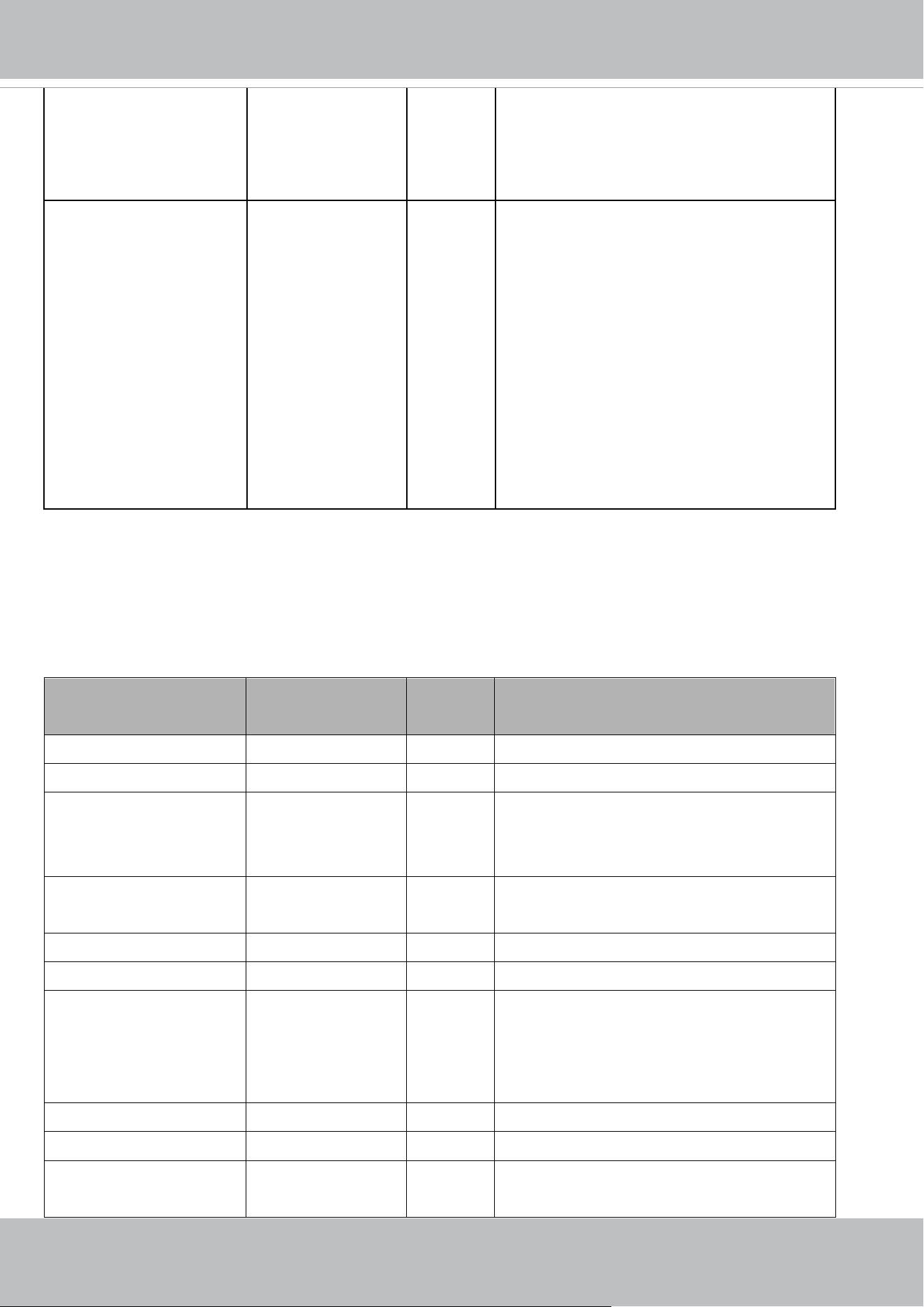
VIVOTEK
User's Manual - 231
* It's recommended to use polygonsd
* This parameter will not be used after the
version number (httpversion) is equal or
greater than 0400a.
height
<Not recommended to use
this>
0 ~ 240 4/4 Height of motion detection window.
* Only available when
"capability_motion_wintype" = rectangle.
* Only available when qvga is listed in
"capability_motion_windomain".
* It's recommended to use polygonsd
* This parameter will not be used after the
version number (httpversion) is equal or
greater than 0400a.
7.17 Tampering detection settings
Group: tampering_c<0~(n-1)> for n channel products
(capability.tampering > 0)
n denotes the value of "capability_nvideoin"
NAME VALUE SECURITY
(get/set)
DESCRIPTION
enable <boolean> 4/4 Enable or disable tamper detection.
threshold 0~100 4/4 Threshold of tamper detection.
duration 10~600 4/4 If tampering value exceeds the "threshold" for
more than "duration" second(s), then tamper
detection is triggered.
ignorewidth 0,<positive integer> 1/7 Indicate the width to offset to start to analysis
the image.
dark_enable <boolean> 4/4 Enable or disable image too dark detection
dark_threshold 0~100 4/4 Threshold of image too dark detection
dark_duration 1~10 4/4 If image too dark value exceeds the
"threshold" for more than "duration"
second(s), then image too dark detection is
triggered.
bright_enable <boolean> 4/4 Enable or disable image too bright detection
bright_threshold 0~100 4/4 Threshold of image too bright detection
bright_duration 1~10 4/4 If image too bright value exceeds the
"threshold" for more than "duration"

VIVOTEK
232 - User's Manual
second(s), then image too bright detection is
triggered.
blurry_enable <boolean> 4/4 Enable or disable image too blurry detection
blurry_threshold 0~100 4/4 Threshold of image too blurry detection
blurry_duration 1~10 4/4 If image too blurry value exceeds the
"threshold" for more than "duration"
second(s), then image too blurry detection is
triggered.
7.18 DDNS
Group: ddns
(capability.protocol.ddns > 0)
NAME VALUE SECURITY
(get/set)
DESCRIPTION
enable <boolean> 6/6 Enable or disable the dynamic DNS.
provider CustomSafe100,
DyndnsDynamic,
DyndnsCustom,
Safe100
6/6 Safe100 => safe100.net
DyndnsDynamic => dyndns.org (dynamic)
DyndnsCustom => dyndns.org
CustomSafe100 =>
Custom server using safe100 method
<provider>_hostname string[128] 6/6 Your DDNS hostname.
<provider>_usernameem
ail
string[64] 6/6 Your user name or email to login to the DDNS
service provider
<provider>_passwordkey string[64] 7/6 Your password or key to login to the DDNS
service provider.
<provider>_servername string[128] 6/6 The server name for safe100.
(This field only exists if the provider is
customsafe100)
7.19 Express link
Group: expresslink
PARAMETER VALUE SECURITY
(get/set)
DESCRIPTION
enable <boolean> 6/6 Enable or disable express link.
state onlycheck,
onlyoffline,
checkonline,
badnetwork
6/6 Camera will check the status of network
environment and express link URL
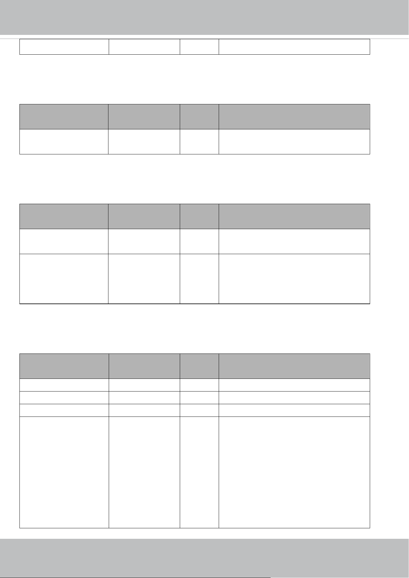
VIVOTEK
User's Manual - 233
url string[64] 6/6 The url user define to link to camera
7.20 UPnP presentation
Group: upnppresentation
NAME VALUE SECURITY
(get/set)
DESCRIPTION
enable <boolean> 6/6 Enable or disable the UPnP presentation
service.
7.21 UPnP port forwarding
Group: upnpportforwarding
NAME VALUE SECURITY
(get/set)
DESCRIPTION
enable <boolean> 6/6 Enable or disable the UPnP port forwarding
service.
upnpnatstatus 0~3 6/7 The status of UPnP port forwarding, used
internally.
0 = OK, 1 = FAIL, 2 = no IGD router, 3 = no
need for port forwarding
7.22 System log
Group: syslog
NAME VALUE SECURITY
(get/set)
DESCRIPTION
enableremotelog <boolean> 6/6 Enable remote log.
serverip <IP address> 6/6 Log server IP address.
serverport 514, 1025~65535 6/6 Server port used for log.
level 0~7 6/6 Levels used to distinguish the importance of
the information:
0: LOG_EMERG
1: LOG_ALERT
2: LOG_CRIT
3: LOG_ERR
4: LOG_WARNING
5: LOG_NOTICE
6: LOG_INFO

VIVOTEK
234 - User's Manual
7: LOG_DEBUG
setparamlevel 0~2 6/6 Show log of parameter setting.
0: disable
1: Show log of parameter setting set from
external.
2. Show log of parameter setting set from
external and internal.
7.23 SNMP
Group: snmp
(capability.protocol.snmp > 0)
NAME VALUE SECURITY
(get/set)
DESCRIPTION
v2 <boolean> 6/6 SNMP v2 enabled. 0 for disable, 1 for enable
v3 <boolean> 6/6 SNMP v3 enabled. 0 for disable, 1 for enable
secnamerw string[31] 6/6 Read/write security name
secnamero string[31] 6/6 Read only security name
authpwrw string[8~128] 7/6 Read/write authentication password
authpwro string[8~128] 7/6 Read only authentication password
authtyperw MD5,SHA 6/6 Read/write authentication type
authtypero MD5,SHA 6/6 Read only authentication type
encryptpwrw string[8~128] 7/6 Read/write passwrd
encryptpwro string[8~128] 7/6 Read only password
encrypttyperw DES 6/6 Read/write encryption type
encrypttypero DES 6/6 Read only encryption type
rwcommunity string[31] 6/6 Read/write community
rocommunity string[31] 6/6 Read only community
syslocation string[128] 6/6 System location
syscontact string[128] 6/6 System contact

VIVOTEK
User's Manual - 235
7.24 Layout configuration
Group: layout
NAME VALUE SECURITY
(get/set)
DESCRIPTION
logo_default <boolean> 1/6 0 => Custom logo
1 => Default logo
logo_link string[128]
http://www.vivotek.
com
1/6 Hyperlink of the logo
logo_powerbyvvtk_hidden <boolean> 1/6 0 => display the power by vivotek logo
1 => hide the power by vivotek logo
custombutton_manualtrig
ger_show
<boolean> 1/6 Show or hide manual trigger (VI) button in
homepage
0 -> Hidden
1 -> Visible
theme_option 1~4 1/6 1~3: One of the default themes.
4: Custom definition.
theme_color_font string[7] 1/6 Font color
theme_color_configfont string[7] 1/6 Font color of configuration area.
theme_color_titlefont string[7] 1/6 Font color of video title.
theme_color_controlback
ground
string[7] 1/6 Background color of control area.
theme_color_configbackg
round
string[7] 1/6 Background color of configuration area.
theme_color_videobackgr
ound
string[7] 1/6 Background color of video area.
theme_color_case string[7] 1/6 Frame color

VIVOTEK
236 - User's Manual
7.25 Privacy mask
Group: privacymask_c<0~(n-1)> for n channel products and m privacy mask window.
n denotes the value of "capability_nvideoin" and m denotes the value of
"capability_videoin_c<0~(n-1)>_nprivacymask"
NAME VALUE SECURITY
(get/set)
DESCRIPTION
enable <boolean> 4/4 Enable privacy mask.
win_i<0~(m-1)>_enable <boolean> 4/4 Enable privacy mask window.
win_i<0~(m-1)>_name string[14] 4/4 Name of the privacy mask window.
win_i<0~(m-1)>_left 0 ~ 320 4/4 Left coordinate of window position.
* Only available when
"capability_image_c<0~(n-1)>_privacymask
_wintype" = rectangle.
win_i<0~(m-1)>_top 0 ~ 240 4/4 Top coordinate of window position.
* Only available when
"capability_image_c<0~(n-1)>_privacymask
_wintype" = rectangle.
win_i<0~(m-1)>_width 0 ~ 320 4/4 Width of privacy mask window.
* Only available when
"capability_image_c<0~(n-1)>_privacymask
_wintype" = rectangle.
win_i<0~(m-1)>_height 0 ~ 240 4/4 Height of privacy mask window.
* Only available when
"capability_image_c<0~(n-1)>_privacymask
_wintype" = rectangle.
win_i<0~(m-1)>_polygo
n
0 ~ 320,0 ~ 240,
0 ~ 320,0 ~ 240,
0 ~ 320,0 ~ 240,
0 ~ 320,0 ~ 240
4/4 Coordinate of polygon window position.
(4 points: x0,y0,x1,y1,x2,y2,x3,y3)
* Only available when
"capability_image_c<n>_privacymask_winty
pe" = polygon.
* Only available when qvga is listed in
"capability_image_c<0~(n-1)>_privacymask
_windomain".
win_i<0~(m-1)>_polygo
npx
0 ~ W,0 ~ H,
0 ~ W,0 ~ H,
0 ~ W,0 ~ H,
4/4 Coordinate of polygon window position.
(4 points: x0,y0,x1,y1,x2,y2,x3,y3)
* Only available when
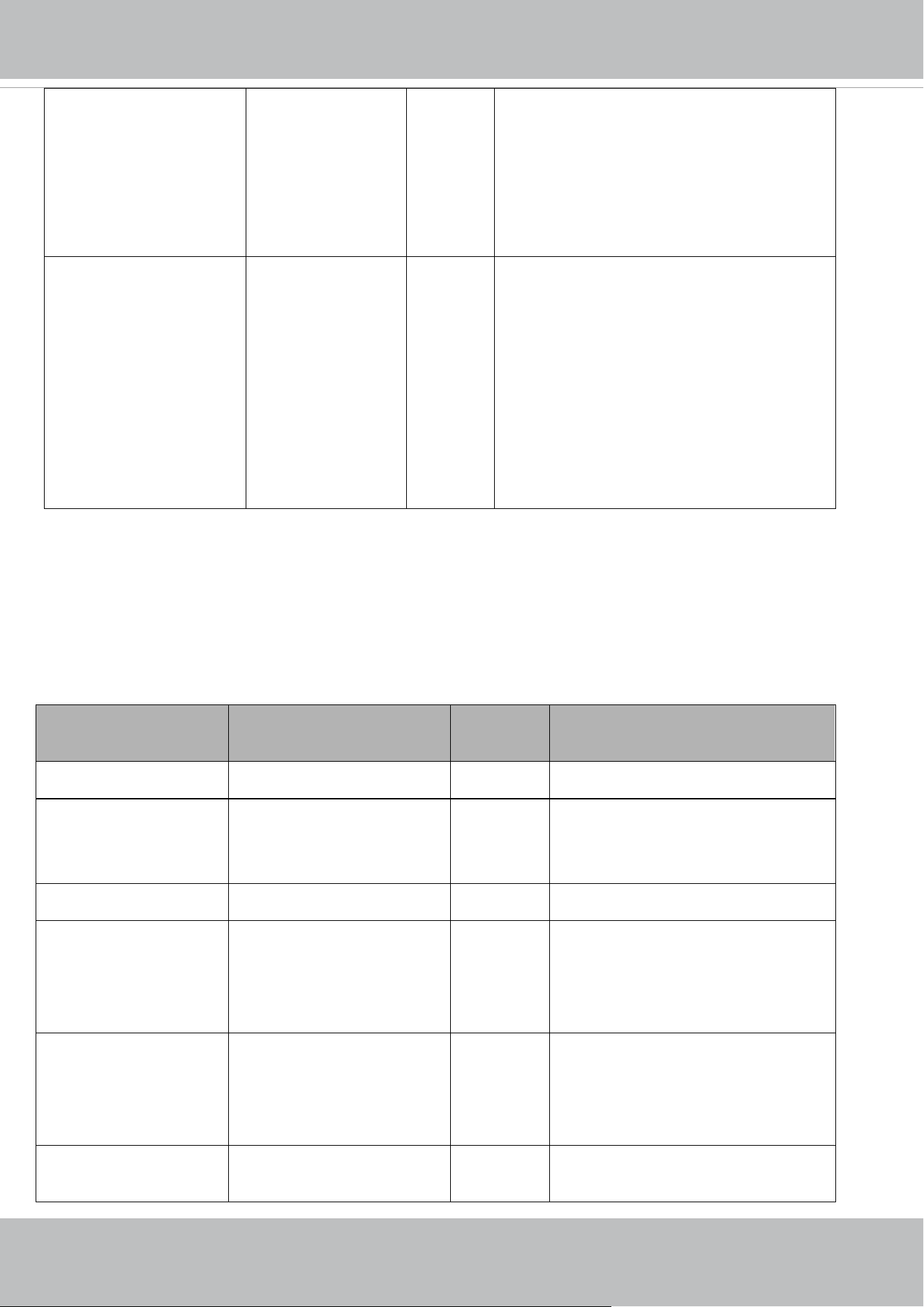
VIVOTEK
User's Manual - 237
0 ~ W,0 ~ H
W: 0~ The current
image width -1
H: 0~ The current
image height -1
"capability_image_c<0~(n-1)>_privacymask
_wintype" = polygon.
* Only available when px is listed in
"capability_image_c<0~(n-1)>_privacymask
_windomain".
win_i<0~(m-1)>_polygo
nstd
0 ~ 9999,0 ~ 9999,
0 ~ 9999,0 ~ 9999,
0 ~ 9999,0 ~ 9999,
0 ~ 9999,0 ~ 9999
4/4 Coordinate of polygon window position.
(4 points: x0,y0,x1,y1,x2,y2,x3,y3)
* Only available when
"capability_image_c<0~(n-1)>_privacymask
_wintype" = polygon.
* Only available when std is listed in
"capability_image_c<0~(n-1)>_privacymask
_windomain".
7.26 3D Privacy mask
Group: privacymask3d_c<0~(n-1)> for n channel products and m privacy mask window.
(capability_image_c<0~(n-1)>_privacymask_wintype = 3Drectangle)
n denotes the value of "capability_nvideoin" and m denotes the value of
"capability_videoin_c<0~(n-1)>_nprivacymask"
NAME VALUE SECURITY
(get/set)
DESCRIPTION
enable <boolean> 4/4 Enable the 3D privacy mask
color 0~"
capability_image_c<0~(n-1)
>_privacymask_ncolor"-1
4/4 Privacy mask color
win_i<0~(m-1)>_name string[40] 4/4 Name of the privacy mask window.
win_i<0~(m-1)>_pan "capability_ptz_c<0~(n-1)>
_minpan" ~
"capability_ptz_c<0~(n-1)>
_maxpan"
4/4 Pan position of window position.
* Only available when bit0 of
"capability_camctrl_c<0~(n-1)>_buil
dinpt" is "1"
win_i<0~(m-1)>_tilt "capability_ptz_c<0~(n-1)>
_mintilt" ~
"capability_ptz_c<0~(n-1)>
_maxtilt"
4/4 Tilt position of window position.
* Only available when bit1 of
"capability_camctrl_c<0~(n-1)>_buil
dinpt" is "1"
win_i<0~(m-1)>_zoom "capability_ptz_c<0~(n-1)>
_minzoom" ~
4/4 Zoom position of window position.
VIVOTEK
238 - User's Manual
"capability_ptz_c<0~(n-1)>
_maxzoom"
win_i<0~(m-1)>_fliped <boolean> 4/4 Flip side of window position.
0: Non-flip side
1: Flip side
7.27 Capability
Group: capability
NAME VALUE SECURITY
(get/set)
DESCRIPTION
api_httpversion <string>
This number start
with 0301a.
0/7 The version of VIVOTEK WebAPI with 4
integers plus 1 alphabet, There are composed
by "major version", "minor version",
"revision","_platform". ex: 0301a_1
Major version
Increase the major version when change,
remove the old features/interfaces or the
firmware has substantially change in
architecture and not able to roll back to
previous version. This may cause
incompatibility with supporting software.
Minor version
Increase the minor version when add new
features/interfaces without change the old
features and interfaces.
Revision
Increase the revision when fix bugs without
change any features of the output.
_platform
This is a constant, it is used to distinguish
between different platforms
API version format:
MMmmr_k
Where "MM" is the major version, "mm" is the
minor version and "r" is the revision.
'M' and 'm' and 'k' are decimal digit from 0 to 9,
while 'r' is an alphabetic.

VIVOTEK
User's Manual - 239
EX: 0302b_1 => Major version = 03, minor
version = 02, revision = b, platform = 1
The 4 integer numbers are WebAPI version, we
use short name: [httpversion] for it in this
document.
The 5th character is model-based version for
API bug-fix and it's default to "a".
Ex: If some APIs in a model does not follow the
API definition of 0301a_1, we will fix them and
change this API value to 0301b_1.
bootuptime <positive integer> 0/7 Server bootup time.
nir
<Not support anymore>
0,
<positive integer>
0/7 Number of IR interfaces.
(Recommand to use
capability_daynight_c<0~"capability_nvideoi
n"-1>_builtinir for built-in IR and
capability_daynight_c<0~"capability_nvideoi
n"-1>_externalir for external IR)
* Not support this parameter anymore when
the version number (httpversion) is equal or
greater than 0301a.
npir 0,
<positive integer>
0/7 Number of PIRs.
ndi 0,
<positive integer>
0/7 Number of digital inputs.
nvi 0,
<positive integer>
0/7 Number of virtual inputs (manual trigger)
ndo 0,
<positive integer>
0/7 Number of digital outputs.
naudioin 0,
<positive integer>
0/7 The number of audio input channel. 0 means
no audio input support.
naudioout 0,
<positive integer>
0/7 The number of audio output channel
nvideoin <positive integer> 0/7 Number of video inputs.
nvideoout 0, <Positive
Integer>
0/7 Number of video out interface.
nvideoinprofile <positive integer> 0/7 Number of video input profiles.
nmediastream <positive integer> 0/7 Number of media stream per channels.
VIVOTEK
240 - User's Manual
naudiosetting
<Not support anymore>
<positive integer> 0/7 Number of audio settings per channel.
* Not support this parameter anymore when
the version number (httpversion) is equal or
greater than 0301a.
* We replace "naudiosetting" with "naudioin".
More details, please refer the parameter
description of "volume_internal" and
"volume_external".
nuart 0,
<positive integer>
0/7 Number of UART interfaces.
nmotion <positive integer> 0/7 The number of motion window.
nmotionprofile 0, <positive
integer>
0/7 Number of motion profiles.
nrecording 0, <positive
integer>
0/7 Number of recording.
* We support this parameter when the version
number (httpversion) is equal or greater than
0309a.
ptzenabled 0, <positive
integer>
0/7 An 32-bit integer, each bit can be set
separately as follows:
Bit 0 => Support camera control function;
0(not support), 1(support)
Bit 1 => (only available when bit0 is 1)
Built-in or external video source;
0(external), 1(built-in)
Bit 2 => (only available when bit0 is 1)
Support pan operation;
0(not support), 1(support)
Bit 3 => (only available when bit0 is 1)
Support tilt operation;
0(not support), 1(support)
Bit 4 => (only available when bit0 is 1)
Support zoom operation;
0(not support), 1(support)
(only available when RS-485 interface is
supported or SD/PZ/PT/PD/video server
series)
Bit 5 => (only available when bit0 is 1)
Support focus operation;
0(not support), 1(support)
VIVOTEK
User's Manual - 241
(only available when RS-485 interface is
supported or SD/PZ/PT/PD/video server
series)
Bit 6 => (only available when bit0 is 1)
Reserved bit; always 0.
Bit 7 => (only available when bit0 is 1)
External or built-in PT;
0(built-in), 1(external)
windowless <boolean> 0/7 Indicate whether to support windowless
plug-in.
evctrlchannel <boolean> 0/7 Indicate whether to support HTTP tunnel for
event/control transfer.
joystick <boolean> 0/7 Indicate whether to support joystick control.
remotefocus
<Not recommended to use
this>
0,<positive integer> 0/7 An 4-bit integer, which indicates the supportive
application of remotefocus.
If the value of this parameter is larger than 0,
it means that the camera supports
remotefocus function.
bit 0 => Indicate whether to support both
zoom and focus function.
bit 1 => Only support zoom function.
bit 2 => Only support focus function.
bit 3 => Currently, this is a reserved bit, and
the default value is 0.
* It's strongly non-recommended to use this.
* This is reserved for compatibility and will not
be used after the version number (httpversion)
is equal or greater than 0400a.
* We replace "capability_remotefocus" with "
capability_image_c0_remotefocus".
npreset 0, <positive
integer>
0/7 Number of preset locations
presettourdirection <boolean> 0/7 Indicate whether to support preset tour
direction function. It means users can choose
which direction the preset tour goes.
* We support this parameter when the version
number (httpversion) is equal or greater than

VIVOTEK
242 - User's Manual
0307a.
eptz 0, <positive
integer>
0/7 For "nvideoin" = 1, the definition is as
following:
A 32-bits integer, each bit can be set
separately as follows:
Bit 0 => 1st stream supports ePTZ or not.
Bit 1 => 2nd stream supports ePTZ or not, and
so on.
For nvideoin >= 2, the definition is different:
First all 32 bits are divided into groups for
channel.
Ex:
nvideoin = 2, bit 0~15 are the 1st group for 1st
channel, bit 16~31 are the 2nd group for 2nd
channel.
nvideoin = 3, bit 0~9 are the 1st group for 1st
channel, bit 10~19 are the 2nd group for 2nd
channel, bit 20~31 are the 3rd group for 3rd
channel.
Then, the 1st bit of the group indicates 1st
stream of a channel support ePTZ or not. The
2nd bit of the group indicates 2nd stream of a
channel support ePTZ or not, and so on.
* For most products, the last stream of a
channel will not support ePTZ. It is reserved
for full view of the channel. For some
dual-stream products, both streams support
ePTZ.
nanystream 0, <positive
integer>
0/7 number of any media stream per channel
iva <boolean> 0/7 Indicate whether to support Intelligent Video
analysis
whitelight
<Not recommended to use
this>
<boolean> 0/7 Indicate whether to support white light led.
* We replace this parameter with
"capability_daynight_c<0~(n-1)>_builtinwled
" when the version number (httpversion) is
equal or greater than 0309d.

VIVOTEK
User's Manual - 243
iris <boolean> 0/7 Indicate whether to support iris control.
supportsd <boolean> 0/7 Indicate whether to support local storage.
fisheye <boolean> 0/7 The parameter is used to determine whether
the product is fisheye or not.
tampering <boolean> 0/7 Indicate whether to support tampering
detection.
tamperingmode tamper,toodark,toob
right,tooblurry
0/7 Available tampering mode list.
* Only available when "capability_tampering"
is 1.
adaptiverecording <boolean> 0/7 Indicate whether to support adaptive
recording.
adaptivestreaming <boolean> 0/7 Indicate whether to support adaptive
streaming.
supporttriggertypes seq,boot,motion,net
workfail,recnotify,ta
mpering,vi,vadp,di,
volalarm,temperatu
re,pir, visignal,
backup,smartsd,
shockalarm,virestor
e
<product
dependent>
0/7 list all the trigger types which are supported in
the camera:
"seq" = Periodic condition
"boot" = System boot
"motion" = Video motion detection
"networkfail" = network connection failure
"recnotify" = Recording notification.
"tampering" = Tamper detection.
"vi" = Virtual input (Manual trigger)
"vadp" = VADP trigger.
"di"= Digital input.
"volalarm" = Audio detection.
"temperature" = Temperature detection.
"pir" = PIR detection.
"visignal" = Video input signal loss.
"backup" = Backing up recorded files.
"smartsd" = Lifetime detection of SD card.
"shockalarm" = Shock detection.
"virestore" = Video input signal restore.
* Only available when [httpversion] >= 0301a
storage_dbenabled <boolean> 0/7 Media files are indexed in database.
protocol_https < boolean > 0/7 Indicate whether to support HTTP over SSL.
protocol_rtsp < boolean > 0/7 Indicate whether to support RTSP.
protocol_sip <boolean> 0/7 Indicate whether to support SIP.
protocol_maxconnection <positive integer> 0/7 The maximum number of allowed
VIVOTEK
244 - User's Manual
simultaneous connections.
protocol_maxgenconnecti
on
<positive integer> 0/7 The maximum general streaming connections .
protocol_rtp_multicast_sc
alable
<boolean> 0/7 Indicate whether to support scalable multicast.
protocol_rtp_multicast_ba
ckchannel
<boolean> 0/7 Indicate whether to support backchannel
multicast.
protocol_rtp_tcp <boolean> 0/7 Indicate whether to support RTP over TCP.
protocol_rtp_http <boolean> 0/7 Indicate whether to support RTP over HTTP.
protocol_spush_mjpeg <boolean> 0/7 Indicate whether to support server push
MJPEG.
protocol_snmp <boolean> 0/7 Indicate whether to support SNMP.
protocol_ipv6 <boolean> 0/7 Indicate whether to support IPv6.
protocol_pppoe <boolean> 0/7 Indicate whether to support PPPoE.
protocol_ieee8021x <boolean> 0/7 Indicate whether to support IEEE802.1x.
protocol_qos_cos <boolean> 0/7 Indicate whether to support CoS.
protocol_qos_dscp <boolean> 0/7 Indicate whether to support QoS/DSCP.
protocol_ddns <boolean> 0/7 Indicate whether to support DDNS.
videoin_type 0, 1, 2 0/7 0 => Interlaced CCD
1 => Progressive CCD
2 => CMOS
videoin_nresolution <positive integer> 0/7 This equals
"capability_videoin_c0_nresolution".
* This is kept for compatibility.
videoin_resolution A list of <WxH>
<product
dependent>
0/7 This equals
"capability_videoin_c0_resolution".
* This is kept for compatibility.
videoin_maxframerate A list of <Integer> 0/7 This equals
"capability_videoin_c0_maxframerate".
* This is kept for compatibility.
videoin_mjpeg_maxframe
rate
A list of <Integer>
and "-"
0/7 This equals
"capability_videoin_c0_mjpeg_maxframerate
".

VIVOTEK
User's Manual - 245
* This is kept for compatibility.
videoin_h264_maxframer
ate
A list of <Integer>
and "-"
0/7 This equals
"capability_videoin_c0_h264_maxframerate".
* This is kept for compatibility.
videoin_codec mjpeg, h264, h265
<product
dependent>
0/7 Available codec of a device, split by comma.
The sequence is not limited.
EX:
FD8183 supports H.264 and MJPEG, then this
is "mjpeg,h264".
IP9171 supports H.264, MJPEG and H.265,
then this is "mjpeg,h264,h265"
videoin_streamcodec A list of <Positive
Integer>
0/7 This equals
"capability_videoin_c0_streamcodec".
* This is kept for compatibility.
videoin_flexiblebitrate <boolean> 0/7 Indicate whether to support
flexible bit rate control.
videoout_codec A list of the available
codec types
separated by
commas
<product
dependent>
0/7 Available codec list.
"-": not supported
timeshift <boolean> 0/7 Indicate whether to support time shift caching
stream.
audio_aec <boolean> 0/7 Indicate whether to support acoustic echo
cancellation.
audio_aecmode auto,
manual
0/7 Indicate the acoustic echo cancellation control
mode.
"auto": control by camera automatically.
"manual": Manually turn on/off the control
mode.
*Only available when
"capability_audio_aec" is "1".
* We support this parameter when the version
number (httpversion) is equal or greater than

VIVOTEK
246 - User's Manual
0306b.
audio_aecaffect -,
maxframerate:fixed
:15
<product
dependent>
0/7
When acousticechocancellationfunction is
enabled, some features may become
malfunction or be forced to a given value. The
affected functions are list here.
The format is "Affect API
name":"Policy":"Description"
"Policy" can be categorized into following
groups:
- (disabled) : UI turns grey and users can't
select it.
- (unchanged) : UI keeps the status as before
and user can't change it.
- (hidden) : UI is hidden.
- (fixed) : UI is fixed to one selection or value.
- (ranged) : UI is fixed to multiple selections or
values.
- (enabled) : UI is checked.
- (notsupport) : the affected function is not
available.
"Affect API name" can be described in
hierarchy, such as
"exposurewin.mode.blc:disabled:" which
means blc exposure window is disabled. API
name can be one word as well, such as
"exposurelevel:fixed:6" which means
exposurelevel is fixed to level 6.
"Description" can be a nonnegative integer or
string or NULL.
For example:
"maxframerate:fixed:15" which means the
max frame rate is 15fps when acousticecho
cancellation
function is enabled.
"-" means no feature is affected.
* Only available when "capability_audio_aec"
is "1".

VIVOTEK
User's Manual - 247
* We support this parameter when the version
number (httpversion) is equal or greater than
0306b.
audio_mic
<Not support anymore>
<boolean> 0/7 Indicate whether to support built-in
microphone input.
* Not support this parameter anymore when
the version number (httpversion) is equal or
greater than 0301a.
* We replace "audio_mic" with "audio_intmic".
audio_intmic <0~Positive
Integer>
0/7 Internal (Built-in) Microphone.
0: Not support
1: Support
Bit 0 for CH0, bit 1 for CH1, and so on.
audio_extmic <0~Positive
Integer>
0/7 External Microphone.
0: Not support
1: Support
Bit 0 for CH0, bit 1 for CH1, and so on.
audio_alarm <0~Positive
Integer>
0/7 0: Not support audio alarm.
1: Support audio alarm.
Bit 0 for CH0, bit 1 for CH1, and so on.
audio_linein
<Not support anymore>
<boolean> 0/7 Indicate whether to support external line
input.
* Not support this parameter anymore when
the version number (httpversion) is equal or
greater than 0301a.
* It will be replaced by audio_intmic and
audio_extmic.
audio_lineout <boolean> 0/7 Indicate whether to support line output.
audio_michardwareswitch <boolean> 0/7 Indicate whether the hardware supports
built-in/external mic switch
audio_headphoneout
<Not support anymore>
<boolean> 0/7 Indicate whether to support headphone
output.
* Not support this parameter anymore when
the version number (httpversion) is equal or
greater than 0301a.
audio_audioclip <boolean> 0/7 Indicate whether to support audio clip
function.

VIVOTEK
248 - User's Manual
* We support this parameter when the version
number (httpversion) is equal or greater than
0309a.
audioin_codec aac4, gamr, g711,
g726, -
<product
dependent>
0/7 Available audio codec. We take comma to split
codec without any space.
"aac4": Advanced Audio Coding (AAC)
"gamr": Adaptive Multi-Rate (AMR)
"g711": G.711
"g726": G.726
"-": Not supported.
audioout_codec g711, -
<product
dependent>
0/7 Available codec list for SIP.
"-": Not supported.
motion_wintype rectangle, polygon,- 0/7 The supported motion window type.
"polygon": The window is a 2D polygon
shape.
"rectangle": The window is a 2D rectangle
shape.
"-": Not supported.
motion_windomain qvga, px, std, - 0/7 The domain to set an motion window.
"qvga": a 320x240 range to represent the
whole image.
"px": Locate a window in the image with
pixels.
"std": A normalized 0~9999 range.
"-": Not supported.
smartstream_support <boolean> 0/7 Indicate whether smart stream is supported.
smartstream_version <integer> 0/7 Number of smart stream version.
* Only available when
"capability_smartstream_support" is 1
smartstream_nstream <positive integer> 0/7 Number of stream that support smart stream.
* Only available when
"capability_smartstream_support" is 1
smartstream_windomain qvga, px, std, - 0/7 The domain to set an focus window.
"qvga": a 320x240 range to represent the
whole image.
"px": Locate a window in the image with

VIVOTEK
User's Manual - 249
pixels.
"std": A normalized 0~9999 range.
"-": Not supported.
* Only available when
"capability_smartstream_support" is 1
smartstream_mode_autot
racking
<boolean> 0/7 Indicate whether autotracking smart stream is
supported.
* Only available when
"capability_smartstream_support" is 1
smartstream_mode_man
ual
<boolean> 0/7 Indicate whether manual smart stream is
supported.
* Only available when
"capability_smartstream_support" is 1
smartstream_mode_hybri
d
<boolean> 0/7 Indicate whether hybrid(autotracking+
manual) smart stream is supported.
* Only available when
"capability_smartstream_support" is 1
smartstream_nwindow_a
utotracking
<positive integer> 0/7 Maximum number of tracking window of
autotracking.
* Only available when
"capability_smartstream_support" is 1
smartstream_nwindow_m
anual
<positive integer> 0/7 Maximum number of tracking window of
manual.
* Only available when
"capability_smartstream_support" is 1
smartstream_nwindow_h
ybrid_autotracking
<positive integer> 0/7 Maximum number of tracking window of
autotracking in hybrid mode.
* Only available when
"capability_smartstream_support" is 1
smartstream_nwindow_h
ybrid_manual
<positive integer> 0/7 Maximum number of tracking window of
manual in hybrid mode.
* Only available when
"capability_smartstream_support" is 1
vadp_supportfeature <positive integer> 0/7 An 32-bit integer, each bit can be set
separately as follows:
Bit 0 => VADP interface
Bit 1 => Capture video raw data
Bit 2 => Support encode jpeg
Bit 3 => Capture audio raw data
Bit 4 => Support event trigger

VIVOTEK
250 - User's Manual
Bit 5 => Support license registration
Bit 6 => Support shared memory API
Bit 7 => Support digital signature of package
Bit 8 => Support snapshot
vadp_npackage <positive integer> 0/7 Indicate the maximum number of VADP
package that can be uploaded to the device.
camctrl_httptunnel
<Not support anymore>
<boolean> 0/7 Indicate whether to support httptunnel.
* Not support this parameter anymore when
the version number (httpversion) is equal or
greater than 0301b.
* It will be replaced by
capability_camctrl_ptztunnel.
camctrl_ptztunnel <boolean> 0/7 Indicate whether to support ptztunnel.
* We support this parameter when the version
number (httpversion) is equal or greater than
0301b.
This equals
"capability_camctrl_c0_ptztunnel".
* This is kept for compatibility.
camctrl_privilege <boolean> 0/7 Indicate whether to support “Manage
Privilege” of PTZ control in the security page.
1: support both /cgi-bin/camctrl/camctrl.cgi
and /cgi-bin/viewer/camctrl.cgi
0: support only /cgi-bin/viewer/camctrl.cgi
This is equivalent
to"capability_camctrl_c0_privilege".
* This is kept for compatibility.
uart_httptunnel <boolean> 0/7 Indicate whether to support HTTP tunnel for
UART transfer.
transmission_mode Tx,
Rx,
Both
0/7 Indicate transmission mode of the machine:
TX = server, Rx = receiver box, Both = DVR.
network_wire <boolean> 0/7 Indicate whether to support Ethernet.
network_wireless <boolean> 0/7 Indicate whether to support wireless.
network_dualmode <boolean> 0/7 Indicate whether network dual mode is
supported.

VIVOTEK
User's Manual - 251
* Only available when
"capability_network_wireless" is "1".
* We support this parameter when the version
number (httpversion) is equal or greater than
0305a.
wireless_s802dot11b <boolean> 0/7 Indicate whether to support wireless
802.11b+.
wireless_s802dot11g <boolean> 0/7 Indicate whether to support wireless 802.11g.
wireless_s802dot11n <boolean> 0/7 Indicate whether to support wireless 802.11n.
wireless_beginchannel 1 ~ 14 0/7 Indicate the begin channel of wireless network
wireless_endchannel 1 ~ 14 0/7 Indicate the end channel of wireless network
wireless_encrypt_wep <boolean> 0/7 Indicate whether to support wireless WEP.
wireless_encrypt_wpa <boolean> 0/7 Indicate whether to support wireless WPA.
wireless_encrypt_wpa2 <boolean> 0/7 Indicate whether to support wireless WPA2.
wireless_apmode_enable <boolean> 0/7 Indicate whether wireless AP mode is
supported.
* Only available when
"capability_network_wireless" is "1".
* We support this parameter when the version
number (httpversion) is equal or greater than
0305a.
wireless_apmode_ssidpref
ix
<string> 0/7 Indicate the prefix of broadcasted SSID when
camera is in wireless AP mode.
* Only available when
"capability_wireless_apmode_enable" is "1".
* We support this parameter when the version
number (httpversion) is equal or greater than
0305a.
derivative_brand <boolean> 0/7 Indicate whether to support the upgrade
function for the derivative brand. For example,
if the value is true, the VVTK product can be
upgraded to VVXX. (TCVV<->TCXX is
excepted)
test_ac <boolean> 0/7 Indicate whether to support test ac key.
version_onvifdaemon <string> 0/7 Indicate ONVIF daemon version
VIVOTEK
252 - User's Manual
version_onviftesttool <string> 0/7 Indicate ONVIF test tool version
media_totalspace <positive integer> 0/7 Available memory space (KB) for media.
media_snapshot_maxpre
event
<positive integer> 0/7 Maximum snapshot number before event
occurred.
media_snapshot_maxpost
event
<positive integer> 0/7 Maximum snapshot number after event
occurred.
media_snapshot_maxsize <positive integer> 0/7 Maximum size (KB) of a snapshot.
media_videoclip_maxsize <positive integer> 0/7 Maximum size (KB) of a videoclip.
media_videoclip_maxleng
th
<positive integer> 0/7 Maximum length (second) of a videoclip.
media_videoclip_maxpree
vent
<positive integer> 0/7 Maximum duration (second) after event
occurred in a videoclip.
image_iristype
<Not recommended to use
this>
<string> 0/7 Indicate iris type.
"piris": P-Iris
"dciris": DC-Iris
"-": No Iris control support
* When "capability_iris"=0, this value must be
"-".
* Note: For some box-type cameras, this value
may be varied depending on mounted lens.
* We replace "capability_image_iristype" with
"capability_image_c0_iristype".
* Reserved for compatibility, and suggest don't
use this since [httpversion] > 0301a
image_focusassist
<Not recommended to use
this>
<boolean> 0/7 Indicate whether to support focus assist.
* We replace "capability_image_ focusassist "
with "capability_image_c0_ focusassist".
* Reserved for compatibility, and suggest don't
use this since [httpversion] > 0301a
localstorage_manageable <boolean> 0/7 Indicate whether manageable local storage is
supported.
* Only available when "capability_supportsd"
is 1 or "capability_storage_dbenabled" is 1.
localstorage_seamless <boolean> 0/7 Indicate whether seamless recording is
supported.
* Only available when "capability_supportsd"
is 1 or "capability_storage_dbenabled" is 1.

VIVOTEK
User's Manual - 253
localstorage_modnum 0,
<positive integer>
0/7 The maximum MOD connection numbers.
* Only available when "capability_supportsd"
is 1 or "capability_storage_dbenabled" is 1.
localstorage_modversion <string> 0/7 Indicate MOD daemon version.
* Only available when "capability_supportsd"
is 1 or "capability_storage_dbenabled" is 1.
localstorage_stormgrversi
on
<string> 0/7 Indicate storage manager daemon version.
* Only available when "capability_supportsd"
is 1 or "capability_storage_dbenabled" is 1.
localstorage_supportedge 0,
<positive integer>
0/7 An 32-bit integer, which indicates the
supportive application of edge storage.
If the value of this parameter is larger than 0,
it means that the camera supports edge
recording function.
bit 0 : It supports to record directly to an
on-board SD-Card.
bit 1~: Currently, they are reserved bit, and
the default value is 0.
* Only available when "capability_supportsd"
is 1 or "capability_storage_dbenabled" is 1.
localstorage_slconnum 0,<positive integer> 0/7 The maximum seamless connection number.
* Only available when "capability_supportsd"
is 1 or "capability_storage_dbenabled" is 1.
localstorage_smartsd <boolean> 0/7 The "Lifetime and Log SD Card" feature allows
users to obtain the card's remaining lifetime
information.
0: Non-support this feature
1: Support this feature
* Only Sony SD card can support this function
now.
* Only available when "capability_supportsd"
is 1 or "capability_storage_dbenabled" is 1.
remotecamctrl_master 0, <positive
integer>
0/7 Indicate whether to support remote auxiliary
camera (master side), this value means
supporting max number of auxiliary camera.
remotecamctrl_slave <boolean> 0/7 Indicate whether to support remote camera
control (slave side).
fisheyelocaldewarp_c<0~
(capability_nvideoin)-1>
0, <positive
integer>
0/7 Indicate the supported streams of local
dewarp. One bit represents one supported

VIVOTEK
254 - User's Manual
<product dependent> stream. The LSB indicates stream 0.
Ex: “3” means stream 0 and stream 1 support
local dewarp.
* Only available when "capability_fisheye" > 0
shockalarm_support <boolean> 0/7 Indicate whether to support the shock
detection.
* We support this parameter when the version
number (httpversion) is equal or greater than
0306e.
layout_redirection <string> 0/7 Indicate which function will be redirected to
the vadp package path.
"-": Not supported.
* We support this parameter when the version
number (httpversion) is equal or greater than
0309a.
Group: capability_camctrl_c<0~(n-1)> n denotes the value of "capability_nvideoin"
(capability_ptzenabled > 0)
* We support this group when the version number (httpversion) is equal or greater than 0303b.
PARAMETER VALUE SECURITY
(get/set)
DESCRIPTION
ptztunnel <boolean> 0/7 Indicate whether to support ptztunnel in this
video input.
privilege <boolean> 0/7 Indicate whether to support “Manage Privilege”
of PTZ control in the security page in this video
input.
1: support both /cgi-bin/camctrl/camctrl.cgi and
/cgi-bin/viewer/camctrl.cgi
0: support only /cgi-bin/viewer/camctrl.cgi
rs485 <boolean> 0/7 An 32-bit integer, each bit can be set separately
as follows:
Bit 0 => support rs485-in
Bit 1 => support rs485-out
buildinpt <boolean> 0/7 An 32-bit integer, each bit can be set separately
as follows:
Bit 0 => support build-in pan
Bit 1 => support build-in tilt

VIVOTEK
User's Manual - 255
zoommodule <boolean> 0/7 Indicate whether to support zoom lens. In our
product, only SD series and IZ series use the
zoom lens.
* Both varifocal and zoom lenses are built with
movable elements that permit changing the
effective focal length. And the key difference
between a varifocal and a zoom lens can be
explained by thinking about a lens that has been
focused on an object at any focal length. A
varifocal will need to be refocused whenever the
focal length is adjusted; the zoom will stay in
focus when the focal length is adjusted.
focusmode auto,onetimeauto,spo
tlight,manual
<product dependent>
0/7 Focus mode selection:
"auto": Camera will automatically adjust the
focus position full time to adapt a clear picture.
"onetimeauto": Camera will automatically
adjust the focus position one time, which follows
any PTZ control.
"spotlight": Camera will automatically adjust
the focus position full time, and to consider a
spotlight avoidance situation.
"manual": Turn off the automatically focus
function. For user to control the focus position
manually as their purpose.
* Only available when
"capability_camctrl_c<0~(n-1)_zoommodule"
is 1.
* We support this parameter when the version
number (httpversion) is equal or greater than
0304a.
Group: capability_ptz_c<0~(n-1)> n denotes the value of "capability_nvideoin"
(capability_ptzenabled > 0 and capability_camctrl_c<0~(n-1)>_zoommodule !=0)
* We support this group when the version number (httpversion) is equal or greater than 0303b.
PARAMETER VALUE SECURITY
(get/set)
DESCRIPTION
panspeedlv 0, <positive integer> 0/7 The maximum speed level of pan motion.
*Only available when bit0 of
"capability_camctrl_c<0~(n-1)>_buildinpt" is
"1"

VIVOTEK
256 - User's Manual
minpan 0, <positive integer> 0/7 The lower limit for pan position.
*Only available when bit0 of
"capability_camctrl_c<0~(n-1)>_buildinpt" is
"1"
maxpan 0, <positive integer> 0/7 The upper limit for pan position.
*Only available when bit0 of
"capability_camctrl_c<0~(n-1)>_buildinpt" is
"1"
minpanangle <integer> 0/7 The lower limit for pan angle.
*Only available when bit0 of
"capability_camctrl_c<0~(n-1)>_buildinpt" is
"1"
maxpanangle <integer> 0/7 The upper limit for pan angle.
*Only available when bit0 of
"capability_camctrl_c<0~(n-1)>_buildinpt" is
"1"
tiltspeedlv 0, <positive integer> 0/7 The maximum speed level of tilt motion.
*Only available when bit1 of
"capability_camctrl_c<0~(n-1)>_buildinpt" is
"1"
mintilt 0, <positive integer> 0/7 The lower limit for tilt position.
*Only available when bit1 of
"capability_camctrl_c<0~(n-1)>_buildinpt" is
"1"
maxtilt 0, <positive integer> 0/7 The upper limit for tilt position.
*Only available when bit1 of
"capability_camctrl_c<0~(n-1)>_buildinpt" is
"1"
mintiltangle <integer> 0/7 The lower limit for tilt angle.
*Only available when bit1 of
"capability_camctrl_c<0~(n-1)>_buildinpt" is
"1"
maxtiltangle <integer> 0/7 The upper limit for tilt angle.
*Only available when bit1 of
"capability_camctrl_c<0~(n-1)>_buildinpt" is
"1"
zoomspeedlv 0, <positive integer> 0/7 The maximum speed level of zoom motion.
*Only available when the value of
"capability_camctrl_c<0~(n-1)>_zoommodule"
is "1"

VIVOTEK
User's Manual - 257
minzoom 0, <positive integer> 0/7 The lower limit for zoom position.
*Only available when the value of
"capability_camctrl_c<0~(n-1)>_zoommodule"
is "1"
maxzoom 0, <positive integer> 0/7 The upper limit for zoom position.
*Only available when the value of
"capability_camctrl_c<0~(n-1)>_zoommodule"
is "1"
maxdzoom 0, <positive integer> 0/7 The upper limit for digital zoom position.
*Only available when the value of
"capability_camctrl_c<0~(n-1)>_zoommodule"
is "1"
focusspeedlv 0, <positive integer> 0/7 The maximum speed level of focus motion.
*Only available when the value of
"capability_camctrl_c<0~(n-1)>_zoommodule"
is "1"
minfocus 0, <positive integer> 0/7 The lower limit for focus position.
*Only available when the value of
"capability_camctrl_c<0~(n-1)>_zoommodule"
is "1"
maxfocus 0, <positive integer> 0/7 The upper limit for focus position.
*Only available when the value of
"capability_camctrl_c<0~(n-1)>_zoommodule"
is "1"
Group: capability_daynight_c<0~(n-1)> n denotes the value of "capability_nvideoin"
PARAMETER VALUE SECURITY
(get/set)
DESCRIPTION
support <boolean> 0/7 Indicate whether the camera supports day/night
mode switch
builtinir <boolean> 0/7 Indicate whether to support built-in IR led.
builtinwled <boolean> 0/7 Indicate whether to support built-in white led.
* We support this parameter when the version
number (httpversion) is equal or greater than
0309d.
externalir <boolean> 0/7 Indicate whether to support external IR led.

VIVOTEK
258 - User's Manual
optimizedir <boolean> 0/7 Indicate whether to support optimized IR control
technology.
* We support this parameter when the version
number (httpversion) is equal or greater than
0307b.
smartir <boolean> 0/7 Indicate whether to support smart IR.
ircutfilter <boolean> 0/7 Indicate whether to support IR cut.
lightsensor <boolean> 0/7 Indicate whether to support light sensor.
blackwhitemode <boolean> 0/7 Indicate whether to support automatically
switch to Black & White display during the night
mode.
* We support this parameter when the version
number (httpversion) is equal or greater than
0302a.
ircutsensitivity_type <string> 0/7 Indicate the cgi interface of
"ircutcontrol_sensitivity".
"options": the value of
"ircutcontrol_sensitivity" parameter is "low,
normal,high".
"normalize": the value of
"ircutcontrol_sensitivity" parameter is "1~100"
"-":not support
* Only available when
"capability_daynight_c<0~(n-1)>_support" is
1.
* We support this parameter when the version
number (httpversion) is equal or greater than
0302a.
ircutsensitivity_supportlevel 0,
<positive integer>
0/7 The value indicate the support strength level of
ircutsensitivity.
* Only available when
"capability_daynight_c<0~(n-1)>_support" is 1
and
"capability_daynight_c<0~(n-1)>_ircutsensitivi
ty_type" is not "-".
* We support this parameter when the version
number (httpversion) is equal or greater than
0302a.

VIVOTEK
User's Manual - 259
extled_interface do,irring
<product dependent>
0/7 The device interface of external IR led:
"do": digital output
"irring":IR ring
* Only available when
"capability_daynight_c<0~(n-1)>_externalir" is
1
* We support this parameter when the version
number (httpversion) is equal or greater than
0304a.
mode auto,daynight,di,di2,d
i3,di4,schedule,-
<product dependent>
0/7 Indicate the day / night switch mode.
"auto": The Camera automatically judges the
current operation mode by the level of ambient
light detected.
"daynight": support day mode and night mode.
In day mode, the camera streams color video.In
night mode, the camera streams black and white
video in low light environments.
"di": the camera automatically switches the
current mode when a ditigal input 1 is triggered.
"di2": the camera automatically switches the
current mode when a ditigal input 2 is triggered.
"di3": the camera automatically switches the
current mode when a ditigal input 3 is triggered.
"di4": the camera automatically switches the
current mode when a ditigal input 4 is triggered.
"schedule": The Camera switches between day
mode and night mode based on a specified
schedule.
"-": not support
* We support this parameter when the version
number (httpversion) is equal or greater than
0309d.
Group: capability_videoin_c<0~(n-1)> n denotes the value of "capability_nvideoin"
PARAMETER VALUE SECURITY
(get/set)
DESCRIPTION

VIVOTEK
260 - User's Manual
lens_type fisheye, fixed,
varifocal, changeable,
motor, ics,-
<product dependent>
0/7
Thelenstypeofthischannel.
"fisheye":Fisheyelens
"fixed":Build‐infixed‐focuslens.
"varifocal":Build‐invarifocallens.
"changeable":changeablelens.Likebox‐type
camera,userscaninstallanyC‐Mountor
CS‐Mountlensastheywish.
"motor":Lenswithmotortosupportzoom,
focus,etc.
"ics":Ani‐CSlensisanintelligentCS‐mountlens
thatcontainsinformationabout,amongother
things,itsowngeometricaldistortionandthe
exactpositionofitszoom,focus,andiris
opening.
"‐":N/A
* Only available when [httpversion] >= 0301a
color_support <boolean> 0/7 1 : camera can select to display color or
black/white video streams.
0: camera do not support this feature.
*Wesupportthisparameterwhentheversion
number(httpversion)isequalorgreaterthan
0310a.
eptz_zoomratio <string> 0/7
Indicate the support zoom ratio of
eptz.
"
‐":notsupportePTZ
*Wesupportthisparameterwhentheversion
number(httpversion)isequalorgreaterthan
0310a.
rotation <boolean> 0/7 Indicate current mode whether support video
rotation

VIVOTEK
User's Manual - 261
rotationaffect -
<product dependent>
0/7 When rotation is enabled, some features may
become malfunction or be forced to a given
value. The affected functions are list here.
The format is "Affect API
name":"Policy":"Description"
"Policy" can be categorized into following
groups:
- (disabled) : UI turns grey and users can't select
it.
- (unchanged) : UI keeps the status as before
and user can't change it.
- (hidden) : UI is hidden.
- (fixed) : UI is fixed to one selection or value.
- (ranged) : UI is fixed to multiple selections or
values.
- (enabled) : UI is checked.
- (notsupport) : the affected function is not
available.
"Affect API name" can be described in hierarchy,
such as "exposurewin.mode.blc:disabled:"
which means blc exposure window is disabled.
API name can be one word as well, such as
"exposurelevel:fixed:6" which means
exposurelevel is fixed to level 6.
"Description" can be a nonnegative integer or
string or NULL.
"-" means no feature is affected.
* When "rotation"=0, this value must be "-"
* We support this parameter when the version
number (httpversion) is equal or greater than
0304b.

VIVOTEK
262 - User's Manual
rotationangle <string> 0/7 The different angles which camera supports for
rotation.
*Only avaliable when
"capability_videoin_c<0~(n-1)>_rotation" is 1.
* We support this parameter when the version
number (httpversion) is equal or greater than
0309b.
orientation flip,mirror,rotation
<product dependent>
0/7 Indicates the camera supports flip, mirror or
rotation.
* We support this parameter when the version
number (httpversion) is equal or greater than
0309b.
streamcodec <positive integer> 0/7 Represent supported codec types of each
stream.
This contains a list of positive integers, split by
comma. Each one stands for a stream, and the
definition is as following:
Bit 0: Support MPEG4.
Bit 1: Support MJPEG
Bit 2: Support H.264
Bit 3: Support H.265
mode 0,<positive integer> 0/7 Indicate current video mode.
nmode <positive integer> 0/7 Indicate how many video modes supported by
this channel.
maxsize <WxH> 0/7 The maximum resolution of all modes in this
channel, the unit is pixel.
nprivacymask 0, <positive integer> 0/7 Number of privacy mask per channel
nresolution <positive integer> 0/7 The maximum resolution options (listed in
"resolution") in current video mode.
resolution A list of <WxH>
<product dependent>
0/7 Resolution options in current video mode. These
options are the possible options for
"videoin_c<n>_s<m>_resolution".
The last one is the maximum resolution in
current mode.
maxresolution A list of <Integer> 0/7 Represent supported maximum resolution of
each stream in current video mode.
* The element number is defined as
"capability_nmediastream".

VIVOTEK
User's Manual - 263
minresolution A list of <Integer> 0/7 Represent supported minimum resolution of
each stream in current video mode.
* The element number is defined as
"capability_nmediastream".
* We support this parameter when the version
number (httpversion) is equal or greater than
0304b.
maxframerate A list of <Integer> 0/7 Indicate frame rate that the video source
outputs in current video mode.
Onetoonemappingtotheresolutionin
"resolution".
*Theelementnumberisdefinedas
"nresolution"inthisgroup.
*Thisparametermaybechangedwhen
"videoin_c<n>_cmosfreq"=50or
"videoin_c<n>_modulation"=pal.
Ex:30fpsischangedto25fps,60fpsischanged
to50fps,andsoon.
mjpeg_maxframerate A list of <Positive
Integer> and "-"
0/7 Maximum fps that the device can encoded with
MJPEG on resolutions in current video mode.
"-" means not support.
* One to one mapping to the resolution in
"resolution".
* The element number is defined as
"nresolution" in this group.
* This parameter may be changed when
"videoin_c<n>_cmosfreq"=50 or
"videoin_c<n>_modulation"=pal.
Ex: 30 fps is changed to 25 fps, 60 fps is
changed to 50 fps, and so on.
* Only available when 'mjpeg' is listed in
"capability_videoin_codec".

VIVOTEK
264 - User's Manual
mjpeg_maxbitrate <positive integer>, - 0/7 Maximum bitrates of MJPEG.
The unit is bps.
"-" means MJPEG does not support bit rate
control.
* Only available when 'mjpeg' is listed in
"capability_videoin_codec".
h264_maxframerate A list of <Positive
Integer> and "-"
0/7 Maximum fps that the device can encoded with
H.264 on resolutions in current video mode.
"-" means not support.
* One to one mapping to the resolution in
"resolution".
* The element number is defined as
"nresolution" in this group.
* This parameter may be changed when
"videoin_c<n>_cmosfreq"=50 or
"videoin_c<n>_modulation"=pal.
Ex: 30 fps is changed to 25 fps, 60 fps is
changed to 50 fps, and so on.
* Only available when 'h264' is listed in
"capability_videoin_codec".
h264_maxbitrate <positive integer> 0/7 Maximum bitrates of H.264.
The unit is bps.
* Only available when 'h264' is listed in
"capability_videoin_codec".
h264_profile baseline,main,high 0/7 Indicate H264 profiles
* Only available when 'h264' is listed in
"capability_videoin_codec".
* We support this parameter when the version
number (httpversion) is equal or greater than
0309a.

VIVOTEK
User's Manual - 265
h265_maxframerate A list of <Positive
Integer> and "-"
0/7 Maximum fps that the device can encoded with
H.265 on resolutions in current video mode.
"-" means not support.
* One to one mapping to the resolution in
"resolution".
* The element number is defined as
"nresolution" in this group.
* This parameter may be changed when
"videoin_c<n>_cmosfreq"=50 or
"videoin_c<n>_modulation"=pal.
Ex: 30 fps is changed to 25 fps, 60 fps is
changed to 50 fps, and so on.
* Only available when 'h265' is listed in
"capability_videoin_codec".
h265_maxbitrate <positive integer> 0/7 Maximum bitrates of H.265.
The unit is bps.
* Only available when 'h265' is listed in
"capability_videoin_codec".
h265_profile main,main10
<product dependent>
0/7 Indicate H265 profiles
* Only available when 'h265' is listed in
"capability_videoin_codec".
* We support this parameter when the version
number (httpversion) is equal or greater than
0309a.
fisheye_mounttype
<Not recommended to use
this>
ceiling, wall, floor
<product dependent>
0/7 Indicate the supported type.
wall mount: 180° panoramic view
ceiling mount: 360° surround view without blind
spots
floor mount: 360° surround view without blind
spots
* Only available when "capability_fisheye" > 0
* It's recommended to use
"capability_videoin_c<0~(n-1)>_mounttype".

VIVOTEK
266 - User's Manual
mounttype ceiling, wall, floor,-
<product dependent>
0/7 Indicate the supported mount type.
"-": not support
* We support this parameter when the version
number (httpversion) is equal or greater than
0309c.
dintraperiod_support <boolean> 0/7 0: Non-support "Dynamic intra frame period"
1: Support "Dynamic intra frame period"
"Dynamic intra frame period" can be used to
reduce bitrate by reducing the number of
I-frame.
* We support this parameter when the version
number (httpversion) is equal or greater than
0301c.
cameraunit_name CU8131,
CU8171,
CU8161-H,
CU8162-H,
CU8163-H,
CU8361-H,
...,
-
<product dependent>
0/7 A "camera unit" name of a split-type camera
system, which the camera unit and the video
core are separated.
-: If the camera is not a split-type camera
system, the value of this parameter is "-".
* We support this parameter when the version
number (httpversion) is equal or greater than
0302b.
cmosfreq_support <boolean> 0/7 0: The power line frequency(50/60Hz) is
detected by camera automatically.
1: The power line frequency(50/60Hz) can be
set by user.
* We support this parameter when the version
number (httpversion) is equal or greater than
0308a.
smartfps_support <boolean> 0/7 Indicate whether to support Smart fps function.
* We support this parameter when the version
number (httpversion) is equal or greater than
0309a.
VIVOTEK
User's Manual - 267
smartq_support <boolean> 0/7 Indicate whether to support Smart Q function.
* We support this parameter when the version
number (httpversion) is equal or greater than
0309a.
Group: capability_videoin_c<0~(n-1)>_localdewarp
(capability_fisheyelocaldewarp_c<0~(capability_nvideoin)-1> > 0)
n denotes the value of "capability_nvideoin"
PARAMETER VALUE SECURITY
(get/set)
DESCRIPTION
typeceilingmount 1O, 1P, 2P, 1R, 4R 0/7 Available dewarp types of ceiling and floor
mount.
typewallmount 1O, 1P, 1R, 4R 0/7 Available dewarp types of wall mount.
resolutionC1P A list of <WxH> 0/7 Available resolutions of 1P mode of ceiling and
floor mount.
resolutionC2P A list of <WxH> 0/7 Available resolutions of 2P mode of ceiling and
floor mount.
resolutionC1R A list of <WxH> 0/7 Available resolutions of 1R mode of ceiling and
floor mount.
resolutionC4R A list of <WxH> 0/7 Available resolutions of 4R mode of ceiling and
floor mount.
resolutionW1P A list of <WxH> 0/7 Available resolutions of 1P mode of wall mount.
resolutionW1R A list of <WxH> 0/7 Available resolutions of 1R mode of wall mount.
resolutionW4R A list of <WxH> 0/7 Available resolutions of 4R mode of wall mount.
Group: capability_videoin_c<0~(n-1)>_mode<0~(m-1)> n denotes the value of "capability_nvideoin", m
denotes the value of "capability_videoin_c<0~(n-1)>_nmode"
PARAMETER VALUE SECURITY
(get/set)
DESCRIPTION
rotation <boolean> 0/7 Indicate this mode whether support video
rotation

VIVOTEK
268 - User's Manual
eptz 0, <positive integer> 0/7 Indicate this mode whether support eptz.
For "nvideoin" = 1, the definition is as
following:
A 32-bits integer, each bit can be set separately
as follows:
Bit 0 => 1st stream supports ePTZ or not.
Bit 1 => 2nd stream supports ePTZ or not, and
so on.
For nvideoin >= 2, the definition is different:
First all 32 bits are divided into groups for
channel.
Ex:
nvideoin = 2, bit 0~15 are the 1st group for 1st
channel, bit 16~31 are the 2nd group for 2nd
channel.
nvideoin = 3, bit 0~9 are the 1st group for 1st
channel, bit 10~19 are the 2nd group for 2nd
channel, bit 20~31 are the 3rd group for 3rd
channel.
Then, the 1st bit of the group indicates 1st
stream of a channel support ePTZ or not. The
2nd bit of the group indicates 2nd stream of a
channel support ePTZ or not, and so on.
* We support this parameter when the version
number (httpversion) is equal or greater than
0304b.
wdrpro 0, 1, 2 0/7 Indicate this mode whether support WDR pro.
0: Non-support WDR Pro
1: Support WDR Pro
2: Support WDR Pro and WDR Pro II
* We support this parameter when the version
number (httpversion) is equal or greater than
0304b.

VIVOTEK
User's Manual - 269
effectivepixel <WxH> 0/7 The visible area of full scene in this video
mode.
The unit is pixel in source.
* If
"effectivepixel"<"capability_videoin_c<0~(n-
1)>_maxsize", then the visible area is located
at the center of full scene.
outputsize <WxH> 0/7 The output size of source, equal to the
captured size by device, in this video mode.
The unit is pixel.
This value is used as a basic coordinate system
for many features, like ePTZ, privacy mask,
motion, etc.
* Source (most for image sensor) may perform
scale or binning, etc on image data, and output
data with smaller size. This parameter is
designed to represent this.
binning 0, 1, 3 0/7 Indicate binning is used or not in this video
mode.
0: No binning
1: 2x2 binning
3: 3x3 binning
* Binning is a technology to increase light
sensitivity by combining multiple pixels to one.
T
he drawback is reduced resolution. We design
this parameter to disclose this information.
nresolution <positive integer> 0/7 How many resolution options in this video
mode.
resolution A list of <WxH> 0/7 Resolution options in this video mode.
The last one is the maximum resolution in this
video mode.
* The element number is defined as
"nresolution" in this group.

VIVOTEK
270 - User's Manual
maxresolution A list of <Integer> 0/7 Represent supported maximum resolution of
each stream in current video mode.
* The element number is defined as
"capability_nmediastream".
minresolution A list of <Integer> 0/7 Represent supported minimum resolution of
each stream in current video mode.
* The element number is defined as
"capability_nmediastream".
* We support this parameter when the version
number (httpversion) is equal or greater than
0304b.
maxframerate A list of <Positive
Integer>
0/7 Indicates frame rate that the video source
outputs in this video mode.
* One to one mapping to the resolution in
"resolution".
* The element number is defined as
"nresolution" in this group.
* This parameter records the frame rate when
"videoin_c<0~(n-1)>_cmosfreq"=60 or
"videoin_c<0~(n-1)>_modulation"=ntsc
maxfps_mjpeg A list of <Positive
Integer> and "-"
0/7 Maximum fps which the device can encoded
with MJPEG on resolutions in this video mode.
"-" means not support.
* One to one mapping to the resolution in
"resolution".
* The element number is defined as
"nresolution" in this group.
* This parameter records the frame rate when
"videoin_c<0~(n-1)>_cmosfreq"=60 or
"videoin_c<0~(n-1)>_modulation"=ntsc
* Only available when 'mjpeg' is listed in
"capability_videoin_codec".

VIVOTEK
User's Manual - 271
maxfps_h264 A list of <Positive
Integer> and "-"
0/7 Maximum fps which the device can encoded
with H.264 on resolutions in this video mode.
"-" means not support.
* One to one mapping to the resolution in
"resolution".
* The element number is defined as
"nresolution" in this group.
* This parameter records the frame rate when
"videoin_c<0~(n-1)>_cmosfreq"=60 or
"videoin_c<0~(n-1)>_modulation"=ntsc
* Only available when 'h264' is listed in
"capability_videoin_codec".
maxfps_h265 A list of <Positive
Integer> and "-"
0/7 Maximum fps which the device can encoded
with H.265 on resolutions in this video mode.
"-" means not support.
* One to one mapping to the resolution in
"resolution".
* The element number is defined as
"nresolution" in this group.
* This parameter records the frame rate when
"videoin_c<0~(n-1)>_cmosfreq"=60 or
"videoin_c<0~(n-1)>_modulation"=ntsc
* Only available when 'h265' is listed in
"capability_videoin_codec".
description <string[128]> 0/7 Description about this mode.
Group: capability_image_c<0~(n-1)> n denotes the value of "capability_nvideoin"
NAME VALUE SECURITY
(get/set)
DESCRIPTION
basicsetting 0, <positive integer> 0/7 A 32-bits integer, each bit can be set
separately as follows:
Bit 0 => Supports Brightness or not.
Bit 1 => Supports Contrast or not.
Bit 2 => Supports Saturation or not.
Bit 3 => Supports Sharpness or not.
Bit 4 => Supports adjusting the image
to proper position horizontally or not.
Bit 5 => Supports adjusting the image

VIVOTEK
272 - User's Manual
to proper position vertically or not.
wdrpro_mode 0, 1, 2 0/7 0: Non-support WDR Pro
1: Support WDR Pro
2: Support WDR Pro and WDR Pro II
wdrpro_strength 0, 1 0/7 0: Non-support tuning strength of
WDR Pro
1: Support tuning strength of WDR Pro
* If
"capability_image_c<0~(n-1)>_wdrp
ro"=1, this may be either 0 or 1.
wdrpro_supportlevel 0, <positive integer> 0/7 This contains a list of positive integers,
split by comma.
If "wdrpro_mode" =1, then the value
indicate the support strength level of
WDR Pro.
If "wdrpro_mode" =2, then the first
number indicate the support strength
level of WDR Pro, and the scecond
number indicate the support strength
level of WDR Pro II.
wdrpro_affect -,
exposurewin.mode:fixed:au
to,
exposurewin.mode.blc:disab
led:,
aespeed:disabled:,
exposurelevel:hidden:,
exposurelevel:fixed:<x>,
exposurelevel:fixed:<x>/<x
>,
exposurelevel:ranged:<x>-
<x>,
exposuremode:fixed:auto
<x>: nonnegative integer
<product dependent>
0/7 When WDR Pro is enabled, some
features may become malfunction or
be forced to a given value. The
affected functions are list here.
The format is "Affect API
name":"Policy":"Description"
"Policy" can be categorized into
following groups:
- (disabled) : UI turns grey and users
can't select it.
- (unchanged) : UI keeps the status as
before and user can't change it.
- (hidden) : UI is hidden.
- (fixed) : UI is fixed to one selection or
value.
- (ranged) : UI is fixed to multiple
selections or values.

VIVOTEK
User's Manual - 273
- (enabled) : UI is checked.
- (notsupport) : the affected function
is not available.
"Affect API name" can be described in
hierarchy, such as
"exposurewin.mode.blc:disabled:"
which means blc exposure window is
disabled. API name can be one word as
well, such as "exposurelevel:fixed:6"
which means exposurelevel is fixed to
level 6.
"Description" can be a nonnegative
integer or string or NULL.
For example:
"exposurelevel:fixed:6/8/12" which
means exposurelevel is fixed to level
6, level 8 and level 12.
"-" means no feature is affected.
* When "wdrpro"=0, this value must
be "-"
wdrpro_description <string> 0/7 Description about WDR Pro mode.
* Only available when
"capability_image_c<0~(n-1)>_wdrp
ro_mode" > 0
wdrc_mode 0, 1 0/7 0: Non-support WDR Enhanced
1: Support WDR Enhanced
wdrc_supportlevel 0, <positive integer> 0/7 Indicate the support strength level of
WDR Enhanced.
wdrc_affect -,
exposurewin.mode:fixed:au
to,
exposurewin.mode.blc:disab
led:,
aespeed:disabled:,
exposurelevel:hidden:,
exposurelevel:fixed:<x>,
exposurelevel:fixed:<x>/<x
>,
0/7 When WDR Enhanced is enabled, some
features may become malfunction or
be forced to a given value. The
affected functions are list here.
The format is "Affect API
name":"Policy":"Description"
"Policy" can be categorized into
following groups:

VIVOTEK
274 - User's Manual
exposurelevel:ranged:<x>-
<x>,
exposuremode:fixed:auto
<x>: nonnegative integer
<product dependent>
- (disabled) : UI turns grey and users
can't select it.
- (unchanged) : UI keeps the status as
before and user can't change it.
- (hidden) : UI is hidden.
- (fixed) : UI is fixed to one selection or
value.
- (ranged) : UI is fixed to multiple
selections or values.
- (enabled) : UI is checked.
- (notsupport) : the affected function
is not available.
"Affect API name" can be described in
hierarchy, such as
"exposurewin.mode.blc:disabled:"
which means blc exposure window is
disabled. API name can be one word as
well, such as "exposurelevel:fixed:6"
which means exposurelevel is fixed to
level 6.
"Description" can be a nonnegative
integer or string or NULL.
For example:
"exposurelevel:fixed:6/8/12" which
means exposurelevel is fixed to level
6, level 8 and level 12.
"-" means no feature is affected.
* When "wdrc"=0, this value must be
"-"
dnr 0,1 0/7 0: Non-support 3D digital noise
reduction
1: Support 3D digital noise reduction
dnrstrength <positive integer> 0/7 Indicate the support strength level of
3D digital noise reduction.
* Only available when
"capability_image_c<0~(n-1)>_dnr"

VIVOTEK
User's Manual - 275
> 0.
* We support this parameter when the
version number (httpversion) is equal
or greater than 0306d.
dnrtype 2d,3d 0/7 Description about DNR type.
* Only available when
"capability_image_c<0~(n-1)>_dnr"
> 0.
* We support this parameter when the
version number (httpversion) is equal
or greater than 0308a.
eis 0,1 0/7 0: Non-support electronic image
stabilizer
1: Support electronic image stabilizer
is_mode eis,
dis,
-
0/7 Indicate the image stabilizer mode.
"eis": electronic image stabilizer
"dis": digital image stabilizer
"-": not support
* We support this parameter when the
version number (httpversion) is equal
or greater than 0302a.
is_strength <boolean> 0/7 0: Non-support tuning strength of
image stabilizer mode.
1: Support tuning strength of image
stabilizer mode.
* Only available when
"capability_image_c<0~(n-1)>_is_m
ode" is not "-".
* We support this parameter when the
version number (httpversion) is equal
or greater than 0302a.
is_supportlevel 0, <positive integer> 0/7 Indicate the support strength level of
image stabilizer mode.
* Only available when

VIVOTEK
276 - User's Manual
"capability_image_c<0~(n-1)>_is_m
ode" is not "-".
* We support this parameter when the
version number (httpversion) is equal
or greater than 0302a.
is_affect -,
minexposure:hidden:,
mingain:hidden:,
wdrpro:unchanged:,
3dnr:unchanged:,
or others
<x>: nonnegative integer
<product dependent>
0/7 When Is mode is not "-", some
features may become malfunction or
be forced to a given value. The
affected functions are list here.
The format is "Affect API
name":"Policy":"Description"
"Policy" can be categorized into
following groups:
- (disabled) : UI turns grey and users
can't select it.
- (unchanged) : UI keeps the status as
before and
user can't change it.
- (hidden) : UI is hidden.
- (fixed) : UI is fixed to one selection or
value.
- (ranged) : UI is fixed to multiple
selections or values.
- (enabled) : UI is checked.
- (notsupport) : the affected function
is not available.
"Affect API name" can be described in
hierarchy, such as
"exposurewin.mode.blc:disabled:"
which means blc exposure window is
disabled. API name can be one word as
well, such as "exposurelevel:fixed:6"
which means exposurelevel is fixed to
level 6.
"Description" can be a nonnegative

VIVOTEK
User's Manual - 277
integer or string or NULL.
"-" means no feature is affected.
* Only available when
"capability_image_c<0~(n-1)>_is_m
ode" is not "-".
* We support this parameter when the
version number (httpversion) is equal
or greater than 0302a.
scenemode_support 0,1 0/7 0: Non-support scene mode
1: Support scene mode
scenemode_supporttype
<product dependent>
visibility,
noiseless,
lpcparkinglot,
lpcstreet,
lpchighway
<product dependent>
0/7 list all the scene mode which are
supported in the camera.
* Only available when
"capability_image_c<0~(n-1)>_
scenemode_support" is 1
wbmode auto,
manual,
rbgain,
widerange,
outdoor,indoor,
sodiumauto,
-
<product dependent>
0/7 Available white balance mode.
"-" means white balance is not
supported.
iristype piris,
dciris,
-
0/7 Indicate iris type.
"piris": P-Iris
"dciris": DC-Iris
"-": No Iris control support
* Note: For some cameras, this value
may be varied depending on mounted
lens.
sensortype rawsensor,
smartsensor,
thermalsensor,
-
0/7 Indicate sensor type.
"rawsensor": Raw sensor
"smartsensor": Smart sensor
"thermalsensor": Thermal sensor
"-": N/A
* We support this parameter when the
version number (httpversion) is equal

VIVOTEK
278 - User's Manual
or greater than 0302a.
exposure_mode 0,1 0/7 0: Non-support exposure control.
1: Support exposure control.
exposure_modetype auto,
shutterpriority,
irispriority,
manual
<product dependent>
0/7 Available mode of exposure setting.
* Only available when
"capability_image_c<0~(n-1)>_
exposure_mode" is 1.
* We support this parameter when the
version number (httpversion) is equal
or greater than 0302a.
exposure_rangetype onevalue,
twovalues
0/7 Support interface of exposure range.
"onevalue": The parameter is a
constant value.
"twovalues": Need two parameters
to indicate the exposure range.
* Only available when
"capability_image_c<0~(n-1)>_
exposure_mode" is 1.
* We support this parameter when the
version number (httpversion) is equal
or greater than 0302a.
exposure_shuttervaluetyp
e
fixed,
maximum,
-
0/7 * One to one mapping to the mode
type in "exposure_modetype".
"fixed": The shutter value is the
assigned value
(videoin_c<0~(n-1)>_shuttervalue).
"maximum": The shutter value can
be up to the assigned value
(videoin_c<0~(n-1)>_shuttervalue).
"-": not support.
* Only available when
"capability_image_c<0~(n-1)>_
exposure_mode" is 1 and
"capability_image_c<0~(n-1)>_expo
sure_rangetype" is "onevalue".
* We support this parameter when the
version number (httpversion) is equal

VIVOTEK
User's Manual - 279
or greater than 0302a.
exposure_gainvaluetype fixed,
maximum,
-
0/7 * One to one mapping to the mode
type in "exposure_modetype".
"fixed": The shutter value is the
assigned value
(videoin_c<0~(n-1)>_gainvalue).
"maximum": The shutter value can
be up to the assigned value
(videoin_c<0~(n-1)>_gainvalue)
"-": not support.
* Only available when
"capability_image_c<0~(n-1)>_
exposure_mode" is 1 and
"capability_image_c<0~(n-1)>_expo
sure_rangetype" is "onevalue".
* We support this parameter when the
version number (httpversion) is equal
or greater than 0302a.
exposure_automode_affe
ct
-,
exposurewin.mode.blc:hidd
en:,
defog:disabled:,
wdrpro:disabled:,
exposurelevel:hidden:,
or others
<x>: nonnegative integer
<product dependent>
0/7 When exposure auto mode is enabled,
some features may become
malfunction or be forced to a given
value. The affected functions are list
here.
The format is "Affect API
name":"Policy":"Description"
"Policy" can be categorized into
following groups:
- (disabled) : UI turns grey and users
can't select it.
- (unchanged) : UI keeps the status as
before and
user can't change it.
- (hidden) : UI is hidden.
- (fixed) : UI is fixed to one selection or
value.
- (ranged) : UI is fixed to multiple
selections or values.

VIVOTEK
280 - User's Manual
- (enabled) : UI is checked.
- (notsupport) : the affected function
is not available.
"Affect API name" can be described in
hierarchy, such as
"exposurewin.mode.blc:disabled:"
which means blc exposure window is
disabled. API name can be one word as
well, such as "exposurelevel:fixed:6"
which means exposurelevel is fixed to
level 6.
"Description" can be a nonnegative
integer or string or NULL.
"-" means no feature is affected.
* Only available when auto is listed in
"capability_image_c<0~(n-1)>_
exposure_modetype" and
"capability_image_c<0~(n-1)>_
exposure_mode" is 1.
* We support this parameter when the
version number (httpversion) is equal
or greater than 0302a.
exposure_shutterpriority
mode_affect
-,
exposurewin.mode.blc:hidd
en:,
defog:disabled:,
wdrpro:disabled:,
exposurelevel:hidden:,
or others
<x>: nonnegative integer
<product dependent>
0/7 When exposure shutter priority mode
is enabled, some features may become
malfunction or be forced to a given
value. The affected functions are list
here.
The format is "Affect API
name":"Policy":"Description"
"Policy" can be categorized into
following groups:
- (disabled) : UI turns grey and users
can't select it.
- (unchanged) : UI keeps the status as
before and

VIVOTEK
User's Manual - 281
user can't change it.
- (hidden) : UI is hidden.
- (fixed) : UI is fixed to one selection or
value.
- (ranged) : UI is fixed to multiple
selections or values.
- (enabled) : UI is checked.
- (notsupport) : the affected function
is not available.
"Affect API name" can be described in
hierarchy, such as
"exposurewin.mode.blc:disabled:"
which means blc exposure window is
disabled. API name can be one word as
well, such as "exposurelevel:fixed:6"
which means exposurelevel is fixed to
level 6.
"Description" can be a nonnegative
integer or string or NULL.
"-" means no feature is affected.
* Only available when shutterpriority is
listed in
"capability_image_c<0~(n-1)>_
exposure_modetype" and
"capability_image_c<0~(n-1)>_
exposure_mode" is 1.
* We support this parameter when the
version number (httpversion) is equal
or greater than 0302a.
exposure_irisprioritymod
e_affect
-,
exposurewin.mode.blc:hidd
en:,
defog:disabled:,
wdrpro:disabled:,
exposurelevel:hidden:,
or others
0/7 When exposure iris priority mode is
enabled, some features may become
malfunction or be forced to a given
value. The affected functions are list
here.
The format is "Affect API
name":"Policy":"Description"

VIVOTEK
282 - User's Manual
<x>: nonnegative integer
<product dependent> "Policy" can be categorized into
following groups:
- (disabled) : UI turns grey and users
can't select it.
- (unchanged) : UI keeps the status as
before and
user can't change it.
- (hidden) : UI is hidden.
- (fixed) : UI is fixed to one selection or
value.
- (ranged) : UI is fixed to multiple
selections or values.
- (enabled) : UI is checked.
- (notsupport) : the affected function
is not available.
"Affect API name" can be described in
hierarchy, such as
"exposurewin.mode.blc:disabled:"
which means blc exposure window is
disabled. API name can be one word as
well, such as "exposurelevel:fixed:6"
which means exposurelevel is fixed to
level 6.
"Description" can be a nonnegative
integer or string or NULL.
"-" means no feature is affected.
* Only available when irispriority is
listed in
"capability_image_c<0~(n-1)>_
exposure_modetype" and
"capability_image_c<0~(n-1)>_
exposure_mode" is 1.
* We support this parameter when the
version number (httpversion) is equal
or greater than 0302a.
exposure_qualitypriority -, 0/7 When exposure quality priority mode

VIVOTEK
User's Manual - 283
mode_affect exposurewin.mode.blc:hidd
en:,
defog:disabled:,
wdrpro:disabled:,
exposurelevel:hidden:,
or others
<x>: nonnegative integer
<product dependent>
is enabled, some features may become
malfunction or be forced to a given
value. The affected functions are list
here.
The format is "Affect API
name":"Policy":"Description"
"Policy" can be categorized into
following groups:
- (disabled) : UI turns grey and users
can't select it.
- (unchanged) : UI keeps the status as
before and
user can't change it.
- (hidden) : UI is hidden.
- (fixed) : UI is fixed to one selection or
value.
- (ranged) : UI is fixed to multiple
selections or values.
- (enabled) : UI is checked.
- (notsupport) : the affected function
is not available.
"Affect API name" can be described in
hierarchy, such as
"exposurewin.mode.blc:disabled:"
which means blc exposure window is
disabled. API name can be one word as
well, such as "exposurelevel:fixed:6"
which means exposurelevel is fixed to
level 6.
"Description" can be a nonnegative
integer or string or NULL.
"-" means no feature is affected.
* Only available when qualitypriority is
listed in
"capability_image_c<0~(n-1)>_

VIVOTEK
284 - User's Manual
exposure_modetype" and
"capability_image_c<0~(n-1)>_
exposure_mode" is 1.
* We support this parameter when the
version number (httpversion) is equal
or greater than 0305a.
exposure_manualmode_a
ffect
-,
exposurewin.mode.blc:hidd
en:,
defog:disabled:,
wdrpro:disabled:,
exposurelevel:hidden:,
or others
<x>: nonnegative integer
<product dependent>
0/7 When exposure manual mode is
enabled, some features may become
malfunction or be forced to a given
value. The affected functions are list
here.
The format is "Affect API
name":"Policy":"Description"
"Policy" can be categorized into
following groups:
- (disabled) : UI turns grey and users
can't select it.
- (unchanged) : UI keeps the status as
before and
user can't change it.
- (hidden) : UI is hidden.
- (fixed) : UI is fixed to one selection or
value.
- (ranged) : UI is fixed to multiple
selections or values.
- (enabled) : UI is checked.
- (notsupport) : the affected function
is not available.
"Affect API name" can be described in
hierarchy, such as
"exposurewin.mode.blc:disabled:"
which means blc exposure window is
disabled. API name can be one word as
well, such as "exposurelevel:fixed:6"
which means exposurelevel is fixed to
level 6.

VIVOTEK
User's Manual - 285
"Description" can be a nonnegative
integer or string or NULL.
"-" means no feature is affected.
* Only available when manual is listed
in "capability_image_c<0~(n-1)>_
exposure_modetype" and
"capability_image_c<0~(n-1)>_
exposure_mode" is 1.
* We support this parameter when the
version number (httpversion) is equal
or greater than 0302a.
exposure_levelrange -,
"0,12"
0/7 Available range for
"videoin_c<0~(n-1)>_exposurelevel"
* When "exposure_mode"=0, this
value must be set to "-".
* Only available when
"capability_image_c<0~(n-1)>_
exposure_mode" is 1.
exposure_winmode auto,
custom,
blc,
hlc
-
<product dependent>
0/7 Available options for
"exposurewin_c<0~(n-1)>_mode"
* "-" means group: exposurewin is not
supported.
* When exposure_mode="0", this
value must be set to "-".
* Only available when
"capability_image_c<0~(n-1)>_
exposure_mode" is 1.
exposure_hlcmode_suppo
rtwindow
<boolean> 0/7 Indicate whether to support exposure
window in hlc mode.
* Only available when
"capability_image_c<0~(n-1)>_
exposure_mode" is 1 and hlc is listed
in "capability_image_c<0~(n-1)>_
exposure_winmode".
exposure_hlcmode_affect -,
or others
0/7 When hlc mode is enabled, some
features may become malfunction or

VIVOTEK
286 - User's Manual
<x>: nonnegative integer
<product dependent>
be forced to a given value. The
affected functions are list here.
The format is "Affect API
name":"Policy":"Description"
"Policy" can be categorized into
following groups:
- (disabled) : UI turns grey and users
can't select it.
- (unchanged) : UI keeps the status as
before and
user can't change it.
- (hidden) : UI is hidden.
- (fixed) : UI is fixed to one selection or
value.
- (ranged) : UI is fixed to multiple
selections or values.
- (enabled) : UI is checked.
- (notsupport) : the affected function
is not available.
"Affect API name" can be described in
hierarchy, such as
"exposurewin.mode.blc:disabled:"
which means blc exposure window is
disabled. API name can be one word as
well, such as "exposurelevel:fixed:6"
which means exposurelevel is fixed to
level 6.
"Description" can be a nonnegative
integer or string or NULL.
"-" means no feature is affected.
* Only available when
"capability_image_c<0~(n-1)>_
exposure_mode" is 1 and hlc is listed
in "capability_image_c<0~(n-1)>_
exposure_winmode".

VIVOTEK
User's Manual - 287
* We support this parameter when the
version number (httpversion) is equal
or greater than 0304a.
exposure_wintype inclusive,
exclusive,
-
0/7 The supported exposure window type.
"inclusive": The image inside a
window is the target area of exposure
control.
"exclusive": The image inside a
window is omitted by exposure
control.
"-": Not supported.
* Only available when
"capability_image_c<0~(n-1)>_
exposure_mode" is 1.
exposure_windomain qvga, px, std, - 0/7 The domain to set an exposure
window.
"qvga": a 320x240 range to
represent the whole image.
"px": Locate a window in the image
with pixels.
"std": A normalized 0~9999 range.
"-": Not supported.
* Only available when
"capability_image_c<0~(n-1)>_
exposure_mode" is 1.
exposure_winnum 0, <Positive Integer> 0/7 Indicate the number of custom
exposure windows.
* If no "custom" is listed in
"exposure_winmode", this should be
0.
* Only available when
"capability_image_c<0~(n-1)>_
exposure_mode" is 1.
exposure_ntsc_totalrange
Alistof<PositiveInteger>
0/7 Available total range for NTSC analog
output.
* Only available when
"capability_image_c<0~(n-1)>_
exposure_mode" is 1.

VIVOTEK
288 - User's Manual
*Wesupportthisparameterwhen
theversionnumber(httpversion)is
equalorgreaterthan0301a.
exposure_pal_totalrange
Alistof<PositiveInteger>
0/7 Available total range for PAL analog
output.
* Only available when
"capability_image_c<0~(n-1)>_
exposure_mode" is 1.
*Wesupportthisparameterwhen
theversionnumber(httpversion)is
equalorgreaterthan0301a.
exposure_maxrange "1,32000",
"1,8000",
-,
or others
<product dependent>
0/7 Available range for
"videoin_c<n>_maxexposure"
"1,32000" => 1s ~ 1/32000s
"1,8000" => 1s ~ 1/8000s
etc.
"-" means maximum exposure time is
not available.
* When "exposure_mode"=0, this
value must be set to "-".
* Only available when
"capability_image_c<0~(n-1)>_
exposure_mode" is 1.
exposure_minrange "1,32000",
"1,8000",
-,
or others
<product dependent>
0/7 Available range for
"videoin_c<n>_minexposure"
"1,32000" => 1s ~ 1/32000s
"1,8000" => 1s ~ 1/8000s
etc.
"-" means minimum exposure time is
not available.
* When "exposure_mode"=0, this
value must be set to "-".
* Only available when
"capability_image_c<0~(n-1)>_
exposure_mode" is 1.
exposure_bracketing_mo
de
<boolean> 0/7
0:Non‐supportAuto
ExposureBracketing

VIVOTEK
User's Manual - 289
(AEB)
1:SupportAutoExposure
Bracketing(AEB)
AutoExposureBracketing(AEB)isa
termthatisusedtosignifyaprocess
wherethecameraautomaticallytakes
twoormoreexposuresbutwith
differentexposurevalues.
*Wesupportthisparameterwhen
theversionnumber(httpversion)is
equalorgreaterthan0310a.
exposure_bracketing_ran
ge
A list of ratio
For example: 2x,3x,4x
0/7
Theinputparameterdecideshow
muchratioofexposurecompensation
willbeexpandedonthenextstream,
whichisbasedontheoriginal
exposuretime(firststream).
*Onlyavailablewhen
"capability_image_c<0~(n‐1)>_
exposure_bracketing_mode"is1.
*Wesupportthisparameterwhen
theversionnumber(httpversion)is
equalorgreaterthan0310a.
privacymask_wintype rectangle,
polygon,
3Drectangle
0/7 The supported mask window type.
"polygon": The window is a 2D
polygon shape.
"rectangle": The window is a 2D
rectangle shape.
"3Drectangle": The window is a 3D
rectangle shape.
privacymask_windomain qvga, px, std, - 0/7 The domain to set an window.
"qvga": a 320x240 range to
represent the whole image.
"px": Locate a window in the image
with pixels.
"std": A normalized 0~9999 range.
"-": Not supported.
privacymask_ncolor
<PositiveInteger>
0/7 Available total color numbers of

VIVOTEK
290 - User's Manual
privacy mask.
agc_maxgain "0,100",
"-"
0/7 Available range for
"videoin_c<n>_maxgain"
“0,100” => 0~100 percent
"-" means "videoin_c<n>_maxgain" is
not available.
agc_mingain "0,100",
"-"
0/7 Available range for
"videoin_c<n>_mingain"
“0,100” => 0~100 percent
"-" means "videoin_c<n>_mingain" is
not available.
flickerless 0,1 0/7 0: Non-support flickerless
1: Support flickerless
flickerlessaffect -,
minexposure:hidden:,
mingain:hidden:,
or others
<x>: nonnegative integer
<product dependent>
0/7 When flickerless is enabled, some
features may become malfunction or
be forced to a given value. The
affected functions are list here.
The format is "Affect API
name":"Policy":"Description"
"Policy" can be categorized into
following groups:
- (disabled) : UI turns grey and users
can't select it.
- (unchanged) : UI keeps the status as
before and
user can't change it.
- (hidden) : UI is hidden.
- (fixed) : UI is fixed to one selection or
value.
- (ranged) : UI is fixed to multiple
selections or values.
- (enabled) : UI is checked.
- (notsupport) : the affected function
is not available.
"Affect API name" can be described in
hierarchy, such as
"exposurewin.mode.blc:disabled:"

VIVOTEK
User's Manual - 291
which means blc exposure window is
disabled. API name can be one word as
well, such as "exposurelevel:fixed:6"
which means exposurelevel is fixed to
level 6.
"Description" can be a nonnegative
integer or string or NULL.
"-" means no feature is affected.
* When "flickerless" = 0, this value
must be "-"
defog_mode 0,1 0/7 0: Non-support defog
1: Support defog
defog_strength 0, 1 0/7 0: Non-support tuning strength of
defog
1: Support tuning strength of defog
* If
"capability_image_c<0~(n-1)>_defog
_mode"=1, this may be either 0 or 1.
defog_supportlevel 0, <positive integer> 0/7 The value indicate the support
strength level of defog.
defog_affect -,
wdrpro:unchanged:,
or others
<x>: nonnegative integer
<product dependent>
0/7 When defog is enabled, some features
may become malfunction or be forced
to a given value. The affected
functions are list here.
The format is "Affect API
name":"Policy":"Description"
"Policy" can be categorized into
following groups:
- (disabled) : UI turns grey and users
can't select it.
- (unchanged) : UI keeps the status as
before and
user can't change it.
- (hidden) : UI is hidden.
- (fixed) : UI is fixed to one selection or

VIVOTEK
292 - User's Manual
value.
- (ranged) : UI is fixed to multiple
selections or values.
- (enabled) : UI is checked.
- (notsupport) : the affected function
is not available.
"Affect API name" can be described in
hierarchy, such as
"exposurewin.mode.blc:disabled:"
which means blc exposure window is
disabled. API name can be one word as
well, such as "exposurelevel:fixed:6"
which means exposurelevel is fixed to
level 6.
"Description" can be a nonnegative
integer or string or NULL.
"-" means no feature is affected.
* When "defog" = 0, this value must be
"-"
aespeed 0,1 0/7 0: Non-support AE speed
1: Support AE speed
aespeedsupportlevel <positive integer> 0/7 The value indicate the support
strength level of aespeed.
* Only available when
"capability_image_c<0~(n-1)>_aesp
eed" is 1.
aespeedsupportsensitivity 0,1 0/7 0: Non-support tuning the sensitivity
of AE converge speed.
1: Support tuning the sensitivity of AE
converge speed.
* Only available when
"capability_image_c<0~(n-1)>_aesp
eed" is 1.
gammacurve 0,1 0/7 0: Non-support tuning Gamma curve
1: Support tuning Gamma curve
lowlightmode -,0,1 0/7
-: Internalparameter,mustnotopen
touser.

VIVOTEK
User's Manual - 293
0: Non-support low light mode
1: Support low light mode
focusassist 0,1 0/7 0: Non-support focus assist
1: Support focus assist
remotefocus 0,<positive integer> 0/7 An 4-bit integer, which indicates the
supportive application of remotefocus
in this channel.
If the value of this parameter is larger
than 0, it means that the camera
supports remotefocus function in this
channel.
bit 0 => Indicate whether to support
both zoom and focus function.
bit 1 => Only support zoom
function.
bit 2 => Only support focus
function.
bit 3 => Currently, this is a reserved
bit, and the default value is 0.
focuswindomain qvga, px, std, - 0/7 The domain to set a focus window.
"qvga": a 320x240 range to
represent the whole image.
"px": Locate a window in the image
with pixels.
"std": A normalized 0~9999 range.
"-": Not supported.
focuswindow_nwindow 0,<positive integer> 0/7 Number of focus window
focuswindow_range <leftrange,rightrange,topra
nge,lowrange>
<product dependent>
0/7 Available range for focuswindow.
* We support this parameter when the
version number (httpversion) is equal
or greater than 0305d.
*-: Not supported.
lensconfiguration_support 0,1 0/7 Indicate whether to support different
image library configuration files for
specific exchangeable lens.
freeze <boolean> 0/7 0: Non-support image freeze feature
1: Support image freeze feature
* We support this parameter when the
version number (httpversion) is equal

VIVOTEK
294 - User's Manual
or greater than 0302a.
autotrack_support <boolean> 0/7 0: Non-support auto tracking feature
1: Support auto tracking feature
* We support this parameter when the
version number (httpversion) is equal
or greater than 0302a.
smartsensor_iristotalrang
e
A list of iris value 0/7 Available total step for iris value.
* We support this parameter when the
version number (httpversion) is equal
or greater than 0302a.
* Only available when
"capability_image_c<0~(n-1)>_sens
ortype" is "smartsensor"
deinterlace_support <boolean> 0/7 Indicate whether to support
deinterlace function.
* We support this parameter when the
version number (httpversion) is equal
or greater than 0308a.
deinterlace_mode spatial, blend 0/7 Spatical mode provides the best image
quality, while Blend mode provides
better image quality (than not using
the deinterlace function at all).
* Only available when
capability_image_c<0~(n-1)>_deinte
rlace_support is 1
lens_alignment <boolean> 0/7 Indicate whether to support lens
alignment function.
* We support this parameter when the
version number (httpversion) is equal
or greater than 0309b.
lens_alignmentlevel <positive integer> 0/7 The value indicate the support level of
alignment.
* Only available when
"capability_image_c<0~(n-1)>_lens_
alignment" is 1.
lens_ldc_support <boolean> 0/7 Indicate whether to support lens
distortion correction function.
* We support this parameter when the
version number (httpversion) is equal
or greater than 0309d.
VIVOTEK
User's Manual - 295
palette_support <boolean> 0/7 Indicate support color palettes or not.
Thermal cameras provide a choice of
color palettes on the camera, that help
quickly distinguish thermal variations
and patterns in an image. The color
tones correspond to the apparent
surface temperatures of the target.
* We support this parameter when the
version number (httpversion) is equal
or greater than 0310a.
palette_mode A list of palette options 0/7 Palette options used in thermal
surveillance.
*Only available when
"capability_image_c<0~(n-1)>_palet
te_support"=1.
* We support this parameter when the
version number (httpversion) is equal
or greater than 0310a.
Group: capability_peripheral_c<0~(n-1)> n denotes the value of "capability_nvideoin"
PARAMETER VALUE SECURITY
(get/set)
DESCRIPTION
devicecontrol <boolean> 0/7 Indicate whether to support the peripheral
device control.
* We support this parameter when the version
number (httpversion) is equal or greater than
0305c.
7.28 Customized event script
Group: event_customtaskfile_i<0~2>
PARAMETER VALUE SECURITY
(get/set)
DESCRIPTION
name string[40] 6/6 Custom script identification of this entry.
date string[4~20] 6/6 Date of custom script.
time string[4~20] 6/6 Time of custom script.
VIVOTEK
296 - User's Manual
7.29 Event setting
Group: event_i<0~2>
PARAMETER VALUE SECURITY
(get/set)
DESCRIPTION
name string[40] 6/6 Identification of this entry.
enable 0, 1 6/6 Enable or disable this event.
priority 0, 1, 2 6/6 Indicate the priority of this event:
“0”= low priority
“1”= normal priority
“2”= high priority
delay 1~999 6/6 Delay in seconds before detecting the next
event.
trigger boot,
di,
p i r,
motion,
seq,
recnotify,
tampering,
vi,
volalarm,
visignal,
vadp,
smartsd
<product dependent>
6/6 Indicate the trigger condition:
"boot" = System boot.
"di"= Digital input.
"pir"= PIR detection.
"motion" = Video motion detection.
"seq" = Periodic condition.
"visignal" = Video input signal loss.
"recnotify" = Recording notification.
"tampering" = Tamper detection.
"vi"= Virtual input (Manual trigger).
"volalarm"= Audio detection.
"smartsd"= Lifetime detection of SD card.
"shockalarm" = Shock detection.
"virestore" = Video input signal restore.
triggerstatus string[40] 6/6 The status for event trigger
di 0,<positive integer> 6/6 Indicate the source id of di trigger.
This field is required when trigger condition is
“di”.
One bit represents one digital input. The LSB
indicates DI 0.
* Only available when "capability_ndi" > 0

VIVOTEK
User's Manual - 297
mdwin 0,<positive integer> 6/6 Indicate the source window id of motion
detection.
This field is required when trigger condition is
“md”.
One bit represents one window.
The LSB indicates the 1
st
window.
For example, to detect the 1
st
and 3
rd
windows,
set mdwin as 5.
mdwin0 0,<positive integer> 6/6 Similar to mdwin. The parameter takes effect
when profile 1 of motion detection is enabled.
vi 0,<positive integer> 6/6 Indicate the source id of vi trigger.
This field is required when trigger condition is
“vi”.
One bit represents one digital input. The LSB
indicates VI 0.
vadp
<product dependent>
0,<positive integer> 6/6 Indicate the source id of vadp event notification.
Each bit corresponds to one vadp source, and
the LSB indicates source id 0.
For example, to detect event from any one of
source id 0, 1 and 3, set vadp to 11.
* Only available when vadp is listed in
"capability_supporttriggertypes"
valevel 0,1 6/6 Select audio detection event.
0: not select
1: select
valevel0 0,1 6/6 Select audio detection profile event.
0: not select
1: select
inter 1~999 6/6 Interval of snapshots in minutes.
This field is used when trigger condition is “seq”.

VIVOTEK
298 - User's Manual
weekday 0~127 6/6 Indicate which weekday is scheduled.
One bit represents one weekday.
bit0 (LSB) = Saturday
bit1 = Friday
bit2 = Thursday
bit3 = Wednesday
bit4 = Tuesday
bit5 = Monday
bit6 = Sunday
For example, to detect events on Friday and
Sunday, set weekday as 66.
begintime hh:mm 6/6 Begin time of the weekly schedule.
endtime hh:mm 6/6 End time of the weekly schedule.
(00:00 ~ 24:00 sets schedule as always on)
lowlightcondition
<product dependent>
0, 1 6/6 Switch on white light LED in low light condition
0 => Do action at all times
1 => Do action in low-light conditions
action_do_i<0~(ndo-1)>_e
nable
<boolean> 6/6 Enable or disable trigger digital output.
* Only available when "capability_ndo" > 0
action_do_i<0~(ndo-1)>_
duration
1~999 6/6 Duration of the digital output trigger in seconds.
* Only available when "capability_ndo" > 0
action_cf_enable <Boolean> 6/6 Enable or disable sending media to SD card.
* Only available when "capability_supportsd" >
0
action_cf_folder string[128] 6/6 Path to store media.
* Only available when "capability_supportsd" >
0
action_cf_media NULL, 0~4,101 6/6 Index of the attached media.
101 means “Recording Notify”
* Only available when "capability_supportsd" >
0
action_cf_datefolder <boolean> 6/6 Enable this to create folders by date, time, and
hour automatically.
* Only available when "capability_supportsd" >
0
action_cf_backup <Boolean> 6/6 Enable or disable the function that send media to
SD card for backup if network is disconnected.
* Only available when "capability_supportsd" >
0

VIVOTEK
User's Manual - 299
action_server_i<0~4>_ena
ble
<boolean> 6/6 Enable or disable this server action.
action_server_i<0~4>_me
dia
NULL, 0~4,101 6/6 Index of the attached media.
101 means "Recording Notify"
action_server_i<0~4>_dat
efolder
<boolean> 6/6 Enable this to create folders by date, time, and
hour automatically.
action_goto_enable
<product dependent>
<boolean> 6/6 Enable/disable ptz goto preset position on event
triggered.
* Only available when "capability_ptzenabled" >
0.
action_goto_name
<product dependent>
string[40] 6/6 Specify the preset name that ptz goto on event
triggered.
* Only available when "capability_ptzenabled" >
0.
action_goto_sync
<product dependent>
<boolean> 6/6 Capture media after moving to the location.
* Only avaliable when the bit4 of
capability_ptzenabled is 1 and the bit7 of
capability_ptzenabled is 0, or
capability_camctrl_c0_zoommodule > 0
action_autotrack_enable
<product dependent>
<boolean> 6/6 Enable/disable auto tracking on event triggerd.
* Only avaliable when the bit4 of
capability_ptzenabled is 1 and the bit7 of
capability_ptzenabled is 0
action_audioclip_enable <boolean> 6/6 Enable/disable the function the play an audio
clip when an event is triggered.
* Only avaliable when
"capability_audio_audioclip" is 1.
action_audioclip_media 0,<positive integer> 6/6 Indicate the source id of audioclip event
notification.
* Only avaliable when
"capability_audio_audioclip" is 1.

VIVOTEK
300 - User's Manual
7.30 Server setting for event action
Group: server_i<0~4>
PARAMETER VALUE SECURITY
(get/set)
DESCRIPTION
name string[40] 6/6 Identification of this entry
type email,
ftp,
http,
ns
6/6 Indicate the server type:
“email” = email server
“ftp” = FTP server
“http” = HTTP server
“ns” = network storage
http_url string[128] 6/6 URL of the HTTP server to upload.
http_username string[64] 6/6 Username to log in to the server.
http_passwd string[64] 7/6 Password of the user.
ftp_address string[128] 6/6 FTP server address.
ftp_username string[64] 6/6 Username to log in to the server.
ftp_passwd string[64] 7/6 Password of the user.
ftp_port 0~65535 6/6 Port to connect to the server.
ftp_location string[128] 6/6 Location to upload or store the media.
ftp_passive <boolean> 6/6 Enable or disable passive mode.
0 = disable passive mode
1 = enable passive mode
email_address string[128] 6/6 Email server address.
email_sslmode <boolean> 6/6 Enable support SSL.
email_port 0~65535 6/6 Port to connect to the server.
email_username string[64] 6/6 Username to log in to the server.
email_passwd string[64] 7/6 Password of the user.
email_senderemail string[128] 6/6 Email address of the sender.
email_recipientemail string[640] 6/6 Email address of the recipient.
ns_location string[128] 6/6 Location to upload or store the media.
ns_username string[64] 6/6 Username to log in to the server.
ns_passwd string[64] 7/6 Password of the user.
ns_workgroup string[64] 6/6 Workgroup for network storage.

VIVOTEK
User's Manual - 301
7.31 Media setting for event action
Group: media_i<0~4>
PARAMETER VALUE SECURITY
(get/set)
DESCRIPTION
name string[40] 6/6 Identification of this entry
type snapshot,
systemlog,
videoclip,
recordmsg
6/6 Media type to send to the server or
store on the server.
snapshot_source 0~"capability_nmediastream"-1 6/6 Indicate the source of media stream.
0 means the first stream.
1 means the second stream and etc.
2 means the third stream and etc.
3 means the fourth stream and etc.
snapshot_prefix string[16] 6/6 Indicate the prefix of the filename.
media_i0=> Snapshot1_
media_i1=> Snapshot2_
media_i2=> Snapshot3_
media_i3=> Snapshot4_
media_i4=> Snapshot5_
snapshot_datesuffix 0, 1 6/6 Add date and time suffix to filename:
1 = Add date and time suffix.
0 = Do not add.
snapshot_preevent 0~"
capability_media_snapshot_maxpr
eevent"
6/6 Indicates the number of pre-event
images.
snapshot_postevent 0~"
capability_media_snapshot_maxpo
stevent"
6/6 Indicates the number of post-event
images.
videoclip_source 0~"capability_nmediastream"-1 6/6 Indicate the source of media stream.
0 means the first stream.
1 means the second stream and etc.
2 means the third stream and etc.
3 means the fourth stream and etc.
videoclip_prefix string[16] 6/6 Indicate the prefix of the filename.
videoclip_preevent 0 ~ "
capability_media_videoclip_maxpre
event"
6/6 Indicates the time for pre-event
recording in seconds.

VIVOTEK
302 - User's Manual
videoclip_maxduration 1 ~ "
capability_media_videoclip_maxlen
gth"
6/6 Maximum duration of one video clip in
seconds.
videoclip_maxsize 50 ~ "
capability_media_videoclip_maxsiz
e"
6/6 Maximum size of one video clip file in
Kbytes.
7.32 Recording
Group: recording_i<0~1>
PARAMETER VALUE SECURITY
(get/set)
DESCRIPTION
name string[40] 6/6 Identification of this entry.
trigger schedule,
networkfail
6/6 The event trigger type
schedule: The event is triggered by schedule
networkfail: The event is triggered by the
failure of network connection.
enable <boolean> 6/6 Enable or disable this recording.
priority 0, 1, 2 6/6 Indicate the priority of this recording:
“0” indicates low priority.
“1” indicates normal priority.
“2” indicates high priority.
source 0~"capability_nmediastream"-1 6/6 Indicate the source of media stream.
0 means the first stream.
1 means the second stream and so on.
maxretentiontime <string> 6/6
T
o specify the expired time for automatic clean
up, and it only takes effect for video clip
generated by recording_i <0~1>.
Format is
“‘P[Y]Y[MM]M[DDD]DT[hh]H[mm]M[ss]S’
, similar with ISO8601 with symbols P
Ex. P7D, it means 7 days. P1DT10H, it means
1 days and 10 hours.
The parameter takes effect when
autocleanup_
maxretentiontime_recording_enabled is
enabled.

VIVOTEK
User's Manual - 303
limitsize <boolean> 6/6 0: Entire free space mechanism
1: Limit recording size mechanism
cyclic <boolean> 6/6 0: Disable cyclic recording
1: Enable cyclic recording
notify <boolean> 6/6 0: Disable recording notification
1: Enable recording notification
notifyserver 0~31 6/6 Indicate which notification server is
scheduled.
One bit represents one application server
(server_i0~i4).
bit0 (LSB) = server_i0.
bit1 = server_i1.
bit2 = server_i2.
bit3 = server_i3.
bit4 = server_i4.
For example, enable server_i0, server_i2, and
server_i4 as notification servers; the
notifyserver value is 21.
weekday 0~127 6/6 Indicate which weekday is scheduled.
One bit represents one weekday.
bit0 (LSB) = Saturday
bit1 = Friday
bit2 = Thursday
bit3 = Wednesday
bit4 = Tuesday
bit5 = Monday
bit6 = Sunday
For example, to detect events on Friday and
Sunday, set weekday as 66.
begintime hh:mm 6/6 Start time of the weekly schedule.
endtime hh:mm 6/6 End time of the weekly schedule.
(00:00~24:00 indicates schedule always on)
prefix string[16] 6/6 Indicate the prefix of the filename.
cyclesize 100~ 6/6 The maximum size for cycle recording in
Kbytes when choosing to limit recording size.
reserveamount 0~15000000 6/6 The reserved amount in Mbytes when
choosing cyclic recording mechanism.

VIVOTEK
304 - User's Manual
dest cf,
0~4
6/6 The destination to store the recorded data.
“cf” means local storage (CF or SD card).
“0” means the index of the network storage.
cffolder string[128] 6/6 Folder name.
maxsize 100~2000 6/6 Unit: Mega bytes.
When this condition is reached, recording file
is truncated.
maxduration 60~3600 6/6 Unit: Second
When this condition is reached, recording file
is truncated.
adaptive_enable <boolean> 6/6 Indicate whether the adaptive recording is
enabled
adaptive_preevent 0~9 6/6 Indicate when is the adaptive recording
started before the event trigger point
(seconds)
adaptive_postevent 0~10 6/6 Indicate when is the adaptive recording
stopped after the event trigger point
(seconds)
7.33 HTTPS
Group: https
(capability.protocol.https > 0)
NAME VALUE SECURITY
(get/set)
DESCRIPTION
enable <boolean> 6/6 To enable or disable secure HTTP.
policy <Boolean> 6/6 If the value is 1, it will force HTTP connection
redirect to HTTPS connection
method auto,
manual,
install
6/6 auto =>Create self-signed certificate
automatically.
manual =>Create self-signed certificate
manually.
install =>Create certificate request and install.
status -3 ~ 1 6/6 Specify the https status.
-3= Certificate not installed
-2 = Invalid public key
-1 = Waiting for certificate
0= Not installed
1 = Active
countryname string[2] 6/6 Country name in the certificate information.
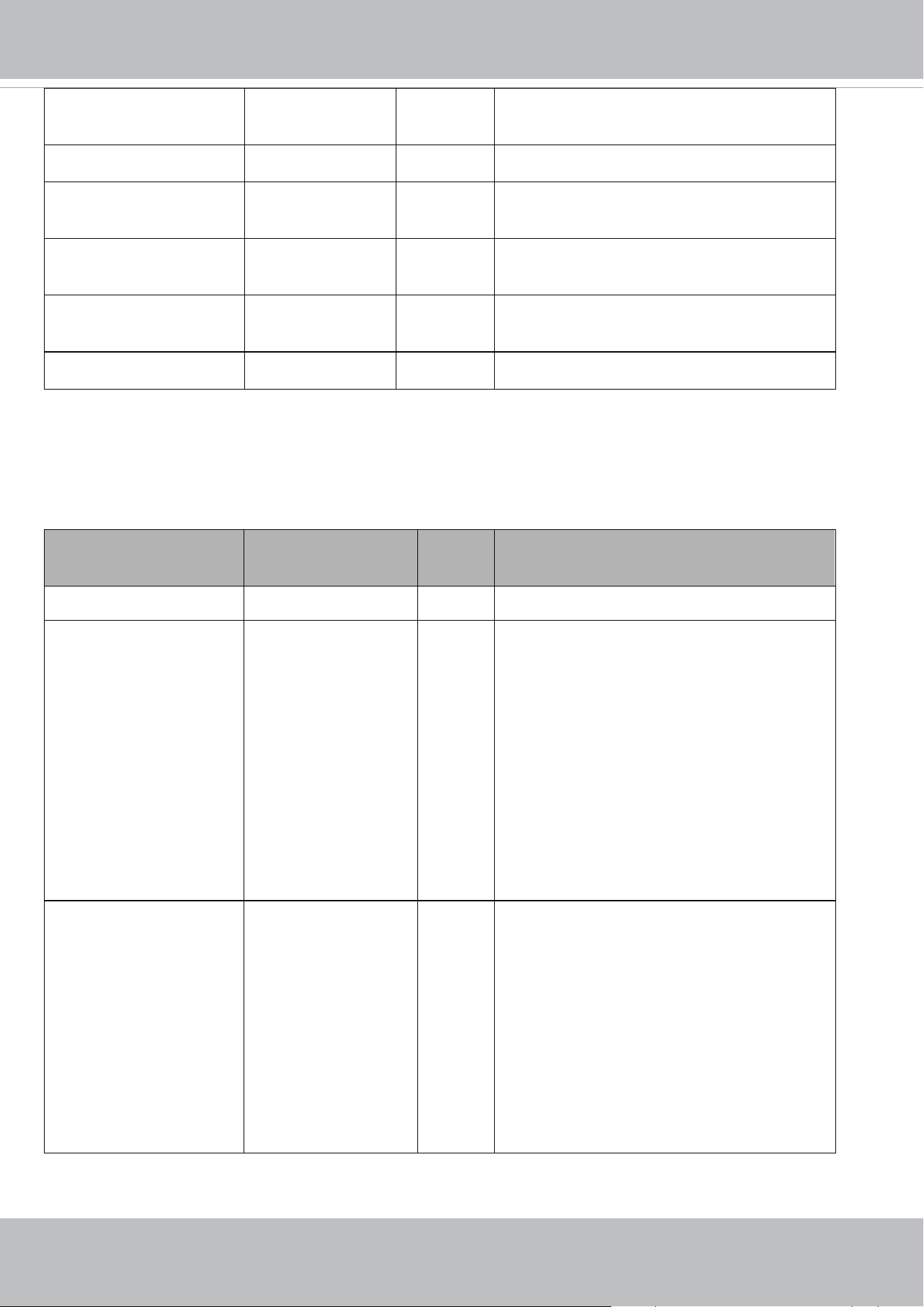
VIVOTEK
User's Manual - 305
stateorprovincename string[128] 6/6 State or province name in the certificate
information.
localityname string[128] 6/6 The locality name in thecertificate information.
organizationname string[64]
VIVOTEK Inc.
6/6 Organization name in the certificate
information.
unit string[64]
VIVOTEK Inc.
6/6 Organizational unit name in thecertificate
information.
commonname string[64]
www.vivotek.com
6/6 Common name in the certificate information.
validdays 0 ~ 3650 6/6 Valid period for the certification.
7.34 Storage management setting
Group: disk_i<0~(n-1)> n is the total number of storage devices.
(capability.storage.dbenabled > 0)
Currently it’s only for local storage (SD, CF card), so n is equal to 1.
PARAMETER VALUE SECURITY
(get/set)
DESCRIPTION
cyclic_enabled <boolean> 6/6 Enable cyclic storage method.
autocleanup_enabled
<Not recommended to use
this>
<boolean> 6/6 Enable automatic clean up method.
Expired and not locked media files will be
deleted.
* For forward compatibility reservations, but
only group disk_i0_autocleanup is effective.
* Not recommended to use this. Please refers
"autocleanup" group.
* This parameter will not be used after the
version number (httpversion) is equal or greater
than 0400a.
autocleanup_maxage
<Not recommended to use
this>
<positive integer> 6/6 To specify the expired days for automatic clean
up.
* For forward compatibility reservations, but
only group disk_i0_autocleanup is effective.
* Not recommended to use this. Please refers
"autocleanup" group.
* This parameter will not be used after the
version number (httpversion) is equal or greater
than 0400a.
Group: autocleanup (capability.localstorage.supportedge > 0)

VIVOTEK
306 - User's Manual
PARAMETER VALUE SECURITY
(get/set)
DESCRIPTION
enabled <boolean> 6/6 Enable automatic clean up method.
Expired and not locked media files will be
deleted.
maxretentiontime_recordin
g_enabled
<boolean> 6/6 Enable automatic clean up method for video clip
generated by recording task.
The parameter takes effect when
autocleanup_enabled is enabled.
maxretentiontime_recordin
g_i<0~1>_maxage
<string> 6/6 To specify the expired time for automatic clean
up, and it only takes effect for video clip
generated by recording_i <0~1>.
Format is
“‘P[Y]Y[MM]M[DDD]DT[hh]H[mm]M[ss]S’
, similar with ISO8601 with symbols P
Ex. P7D, it means 7 days. P1DT10H, it means 1
days and 10 hours.
The parameter takes effect when autocleanup_
maxretentiontime_recording_enabled is
enabled.
maxretentiontime_others_e
nabled
<boolean> 6/6 Enable automatic clean up method for all media
files except media files generated by recording
task.
The parameter takes effect when
autocleanup_enabled is enabled.

VIVOTEK
User's Manual - 307
maxretentiontime_others_
maxage
<string> 6/6 To specify the expired time for automatic clean
up, and it takes effect for all media files except
media files generated by recording task.
Format is
“‘P[Y]Y[MM]M[DDD]DT[hh]H[mm]M[ss]S’
, similar with ISO8601 with symbols P
Ex. P7D, it means 7 days. P1DT10H, it means 1
days and 10 hours.
The parameter takes effect when
autocleanup_maxretentiontime_others_enabled
is enabled.
7.35 Region of interest
Group: roi_c<0~(n-1)> for n channel product and m is the index of video stream which support ePTZ.
(capability.eptz > 0 or capability_fisheye = 1)
PARAMETER VALUE SECURITY
(get/set)
DESCRIPTION
s<0~(m-1)>_home <W,H>
<product dependent>
1/6 ROI left-top corner coordinate.* If the minimal
window size is 64x64, then the
"win_i0_home"=(0~resolution_W-64,
0~resolution_H-64), which the resolution is the
value in current stream.
* If the stream doesn’t support ePTZ, the
permissions of this parameter must be set as
1/7.
s<0~(m-1)>_size <WxH>
<product dependent>
1/6 ROI width and height. The width value must be
multiples of 16 and the height value must be
multiples of 8
* The minimal window size is 64x64.
* If the stream doesn’t support ePTZ, the
permissions of this parameter must be set as
1/7.

VIVOTEK
308 - User's Manual
7.36 ePTZ setting
Group: eptz_c<0~(n-1)> for n channel product.
(capability.eptz > 0 or capability_fisheye = 1)
PARAMETER VALUE SECURITY
(get/set)
DESCRIPTION
osdzoom
<Not recommended to use
this>
<boolean> 1/4 Indicates multiple of zoom in is “on-screen
display” or not.
* Reserved for compatibility, and suggest don't
use this since [httpversion] > 0302a
* We replace "eptz_c<0~(n-1)>_osdzoom" with
" videoin_c<0~(n-1)>_zoomratiodisplay".
smooth <boolean> 1/4 Enable the ePTZ "move smoothly" feature
tiltspeed -5 ~ 5 1/4 Tilt speed
* Only available when "capability_fisheye" is 1
1/7 Tilt speed
(It should be set by eCamCtrl.cgi rather than by
setparam.cgi.)
panspeed -5 ~ 5 1/4 Pan speed
* Only available when "capability_fisheye" is 1
1/7 Pan speed
(It should be set by eCamCtrl.cgi rather than by
setparam.cgi.)
zoomspeed -5 ~ 5 1/4 Zoom speed
* Only available when "capability_fisheye" is 1
1/7 Zoom speed
(It should be set by eCamCtrl.cgi rather than by
setparam.cgi.)
autospeed 1 ~ 5 1/4 Auto pan/patrol speed
* Only available when "capability_fisheye" is 1
1/7 Auto pan/patrol speed
(It should be set by eCamCtrl.cgi rather than by
setparam.cgi.)
rotatespeed 1 ~ 5 1/4 Rotate speed (only for Fisheye series)
* Only available when "capability_fisheye" is 1
and
"capability_fisheyelocaldewarp_c<0~(n-1)>" is
0

VIVOTEK
User's Manual - 309
Group: eptz_c<0~(n-1)>_s<0~(m-1)> for n channel product and m is the index of video stream which
support ePTZ if capability_eptz > 0; m is the index of stream number if capability_fisheye = 1. (capability.eptz >
0 or capability_fisheye = 1)
PARAMETER VALUE SECURITY
(get/set)
DESCRIPTION
patrolseq string[120] 1/4 The patrol sequence of ePTZ. All the patrol
position indexes will be separated by ","
patroldwelling string[160] 1/4 The dwelling time (unit: second) of each patrol
point, separated by “,”.
preset_i<0~19>_name string[40] 1/4 Name of ePTZ preset.
* Only available when "capability_fisheye" is 1
1/7 Name of ePTZ preset.
(It should be set by ePreset.cgi rather than by
setparam.cgi.)
preset_i<0~19>_pos <W,H>
<product dependent>
1/4 Left-top corner coordinate of the preset.
* Only available when "capability_fisheye" is 1
1/7 Left-top corner coordinate of the preset.
(It should be set by ePreset.cgi rather than by
setparam.cgi.)
preset_i<0~19>_size <WxH>
<product dependent>
1/4 Width and height of the preset.
* Only available when "capability_fisheye" is 1
1/7 Width and height of the preset.
(It should be set by ePreset.cgi rather than by
setparam.cgi.)
7.37 Focus Window setting
Group: focuswindow_c<0~(n-1)> for n channel products
n denotes the value of "capability_nvideoin".
(capability_image_c<0~(n-1)>_focuswindow_nwindow > 0)
PARAMETER VALUE SECURITY
(get/set)
DESCRIPTION
win_i0_enable <boolean> 4/4 Enable or disable the window.
win_i0_home <W,H>
<product dependent>
4/4 Left-top corner coordinate of the window.
* If the minimal window size is 192x144, then
the "win_i0_home"=(0~resolution_W-192,
0~resolution_H-144), which the resolution is
the value in current stream.

VIVOTEK
310 - User's Manual
win_i0_size <WxH>
<product dependent>
4/4 Width and height of the window.
* The minimal window size is 192x144
7.38 Seamless recording setting
Group: seamlessrecording
(capability.localstorage.seamless> 0)
PARAMETER VALUE SECURITY
(get/set)
DESCRIPTION
diskmode seamless,
manageable
1/6 “seamless” indicates enable seamless recording.
“manageable” indicates disable seamless
recording.
maxconnection 3 1/7 Maximum number of connected seamless
streaming.
enable <boolean> 1/7 Indicate whether seamless recording is
recording to local storage or not at present.
(Read only)
guid<0~2>_id string[127] 1/7 The connected seamless streaming ID.
(Read only)
guid<0~2>_number 0~3 1/7 Number of connected seamless streaming with
guid<0~2>_id.
(Read only)
7.39 VIVOTEK Application Development Platformsetting
Group: vadp
NAME VALUE SECURITY
(get/set)
DESCRIPTION
version <string> 6/7 Indicate the VADP version.
resource_total_memory 0,<positive integer> 6/7 Indicate total available memory size for VADP
modules.
resource_total_storage 0,<positive integer> 6/7 Indicate total size of the internal storage
space for storing VADP modules.
resource_free_memory 0,<positive integer> 6/7 Indicate free memory size for VADP modules.
resource_free_storage 0,<positive integer> 6/7 Indicate current free storage size for
uploading VADP modules.
module_number 0,<positive integer> 6/7 Record the total module number that already
stored in the system.
module_order string[40] 6/6 The execution order of the enabled modules.
module_save2sd <boolean> 6/6 Indicate if the module should be saved to SD

VIVOTEK
User's Manual - 311
card when user want to upload it.
If the value is false, save module to the
internal storage space and it will occupy
storage size.
number string[128] 6/7 This number is used to register license key for
VADP application.
Group: vadp_module_i<0~(n-1)> for n VADP package number (capability_vadp_npackage > 0)
n denotes the value of "capability_vadp_npackage".
NAME VALUE SECURITY
(get/set)
DESCRIPTION
enable <boolean> 6/6 Indicate if the module is enabled or not.
If yes, also add the index of this module to the
module_order.
name string[40] 6/6 Module name
extendedname string[40] 6/6 Extended module name. If this value is not
blank, it will be shown on the VADP UI first
instead of vadp_module_i<n>_name.
url string[120] 6/6 Define the URL string after the IP address if the
module provides it own web page.
vendor string[40] 6/6 The provider of the module.
vendorurl string[120] 6/6 URL of the vendor.
version string[40] 6/6 Version of the module.
license string[40] 6/6 Indicate the license status of the module.
licmsg string[128] 6/6 Indicate the message that will be show on
license status when mouse over.
path string[40] 6/6 Record the storage path of the module.
initscr string[40] 6/6 The script that will handle operation
commands from the system.
status string[40] 6/6 Indicate the running status of the module.
statmsg string[128] 6/6 Indicate the message that will be show on the
running status when mouse over.
vvtklicensemec string[40] 6/7 Indicate the module use VIVOTEK license
mechanism
Group: vadp_schedule_i<0~(n-1)> for n VADP package number
n denotes the value of "capability_vadp_npackage".
(Only available when "capability_vadp_npackage" > 0 and the version number of "vadp_version" >= "1.3.2.0")
NAME VALUE SECURITY DESCRIPTION
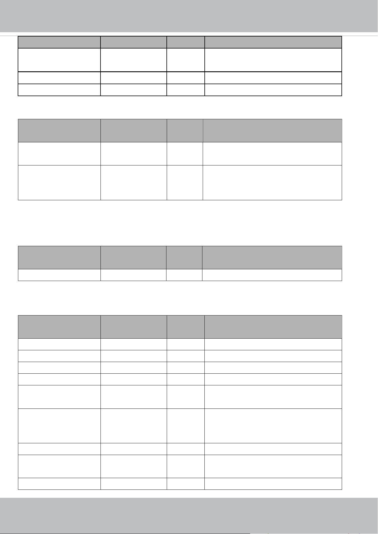
VIVOTEK
312 - User's Manual
(get/set)
enable <boolean> 6/6 Enable or disable the schedule mode to
control the execution of the VADP package
begintime hh:mm 6/6 Begin time of the schedule
endtime hh:mm 6/6 End time of the schedule
Group: vadp_event
NAME VALUE SECURITY
(get/set)
DESCRIPTION
ntrigger 0,<positive integer> 6/7 Indicate the number of topics to be transferred
to event manager for trigger.
triggerlist_i<0~(n-1)>_to
pic
string[256] 6/6 Indicate the event notification with this topic
will be transferred to event manager as trigger.
n is equal to ntrigger above.
7.40 camera PTZ control
Group: camctrl
(capability.camctrl.ptztunnel > 0)
NAME VALUE SECURITY
(get/set)
DESCRIPTION
enableptztunnel <boolean> 1/4 Enable PTZ tunnel for camera control.
Group: camctrl_c<0~(n-1)> for n channel products (capability.ptzenabled > 0)
n denotes the value of "capability_nvideoin" and k denotes the value of "capability_npreset"
NAME VALUE SECURITY
(get/set)
DESCRIPTION
panspeed -5 ~ 5 1/4 Pan speed
tiltspeed -5 ~ 5 1/4 Tilt speed
zoomspeed -5 ~ 5 1/4 Zoom speed
focusspeed -5 ~ 5 1/4 Auto focus speed
patrolseq string[120] 1/4 (For external device)
The indexes of patrol points, separated by “,”
patroldwelling string[160] 1/4 (For external device)
The dwelling time of each patrol point,
separated by “,”
preset_i<0~(k-1)>_name string[40] 1/4 Name of the preset location.
preset_i<0~(k-1)>_
dwelling
0 ~ 999 1/4 The dwelling time of each preset location
uart 0 ~ " 1/4 Select corresponding uart

VIVOTEK
User's Manual - 313
capability_nuart"-1 (capability.nuart>0).
cameraid 0~255 1/4 Camera ID controlling external PTZ camera.
isptz 0 ~ 2 1/4 0: disable PTZ commands.
1: enable PTZ commands with PTZ driver.
2: enable PTZ commands with UART tunnel.
* Only available when bit7 of
capability_ptzenabled is 1
disablemdonptz <boolean> 1/4 Disable motion detection on PTZ operation.
7.41 camera PTZ control (IZ series)
Group: camctrl_c<0~(n-1)> for n channel products
(capability_camctrl_c0_zoommodule = 1 and
capability_camctrl_c0_buildinpt = 0)
n denotes the value of "capability_nvideoin" and k denotes the value of "capability_npreset"
NAME VALUE SECURITY
(get/set)
DESCRIPTION
ccdtype string[16] 6/7 (Internal used, read only)
motortype string[16] 6/7 (Internal used, read only)
cameraid 0 ~ 255 1/4 Camera ID controlling external PTZ
camera.
Note:
Please set your speed dome to the
appropriate baud rate, and Camera ID,
e.g. 2400bps, camera ID 1,2,3,,,,etc.
All Camera IDs on the same controlling
system (NVR or rs485 keyboard) have
to be distinct.
Therefore, once you send a controlling
signal, each camera will only accept the
inputs with the corresponding ID.
panspeed -5 ~ 5 1/4 Pan speed
tiltspeed -5 ~ 5 1/4 Tilt speed
zoomspeed -5 ~ 5 1/4 Zoom speed
autospeed -5 ~ 5 1/4 Auto pan speed
focusspeed -5 ~ 5 1/4 Auto focus speed
focusmode auto,onetimeauto,spotligh
t,manual
* Available values are
listed in
"capability_camctrl_c<0~
1/4 Indicate the focus control mode.

VIVOTEK
314 - User's Manual
(n-1)>_focusmode"
uart 0 ~ "capability_nuart"-1 1/4 Select corresponding uart
(capability.nuart>0).
isptz 0 ~ 2 1/4 0: disable PTZ commands.
1: enable PTZ commands with PTZ
driver.
2: enable PTZ commands with UART
tunnel.
* Only available when bit7 of
capability_ptzenabled is 1
preset_i<0~(k-1)>_name string[40] 1/4 Name of the preset location.
preset_i<0~(k-1)>_zoom capability_ptz_c<0~(n-1)
>_minzoom ~
capability_ptz_c<0~(n-1)
>_maxzoom
1/4 Zoom position at each preset location.
preset_i<0~(k-1)>_focus capability_ptz_c<0~(n-1)
>_minfocus ~
capability_ptz_c<0~(n-1)
>_maxfocus
1/4 Focus position at each preset location.
preset_i<0~(k-1)>_
dwelling
0 ~ 999 1/4 The dwelling time of each preset
location
preset_i<0~(k-1)>_focus
setting
sync,
fixcurrent
1/4 The focus mode of each preset, which is
essential and should be grouped with
“preset_i<0~(k-1)>_name.”
* We support this parameter when the
version number (httpversion) is equal or
greater than 0305b.
patrolseq string[120] 1/4 (For external device)
The indexes of patrol points, separated
by “,”
patroldwelling string[160] 1/4 (For external device)
The dwelling time of each patrol point,
separated by “,”
disablemdonptz <boolean> 1/4 Disable motion detection on PTZ
operation.
defaulthome <boolean> 1/4 This field tells system to use default
home position or not.
axisz capability_ptz_c<0~(n-1)
>_minzoom ~
capability_ptz_c<0~(n-1)
1/4 Custom home zoom position.
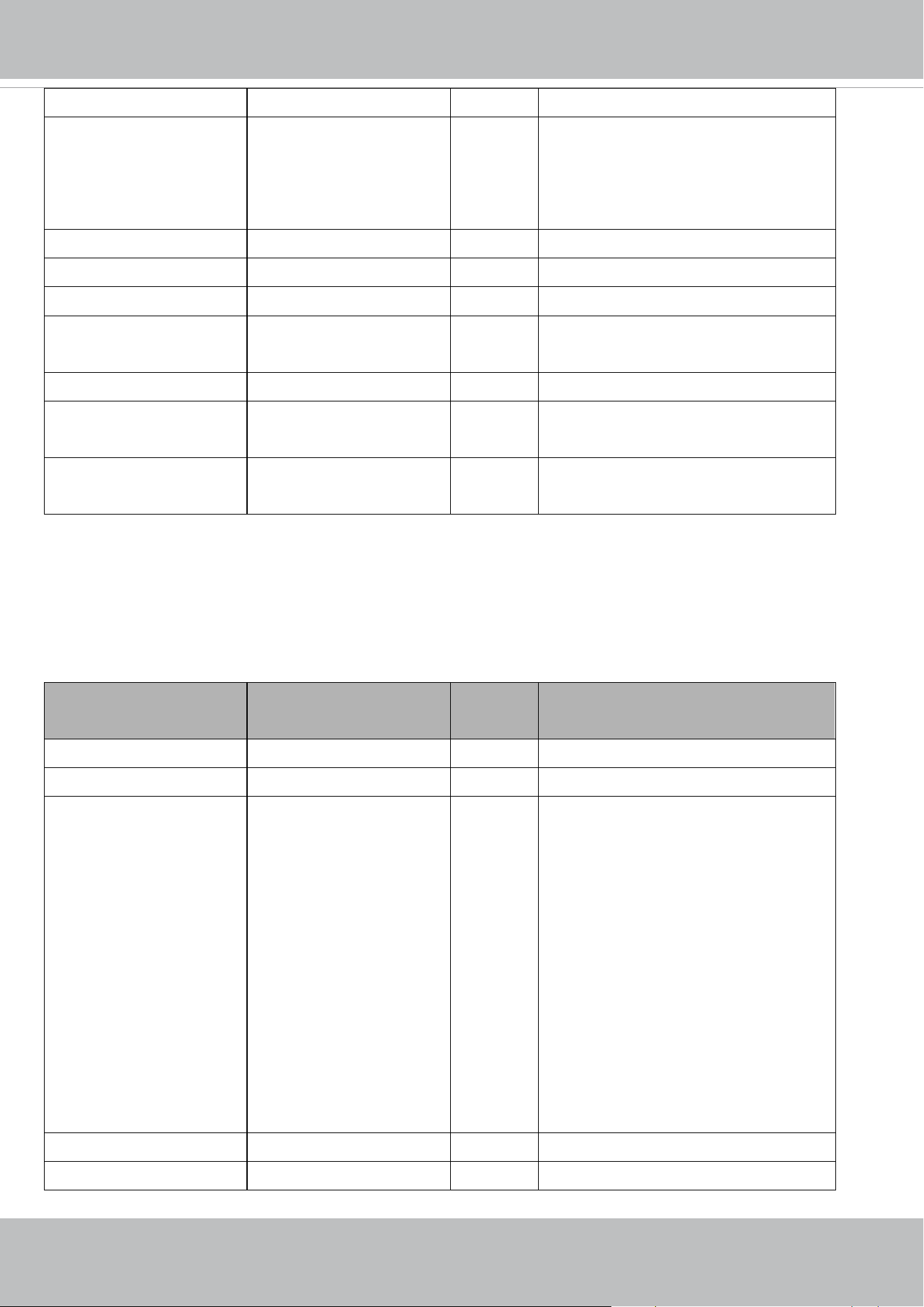
VIVOTEK
User's Manual - 315
>_maxzoom
axisf capability_ptz_c<0~(n-1)
>_minfocus ~
capability_ptz_c<0~(n-1)
>_maxfocus
1/4 Custom home focus position.
digitalzoom <boolean> 1/4 Enable/disable digital zoom
zoomenhance <boolean> 1/4 Enable /disable zoom enhancement
returnhome <boolean> 1/4 Enable/disable return home while idle.
returnhomeinterval 1~999 1/4 While idle over this time interval, idle
action will be taken.
idleaction_enable <boolean> 1/4 Enable/disable idle action while idle
idleaction_type home 1/4 This field tells what kind of action should
be taken while idle.
idleaction_interval 1~999 1/4 While idle over this time interval, idle
action will be taken.
7.42 camera PTZ control (SD series)
Group: camctrl_c<0~(n-1)> for n channel products
(the bit7 of capability_ptzenabled is 0 and the bit4 of
capability_ptzenabled is 1)
n denotes the value of "capability_nvideoin" and k denotes the value of "capability_npreset"
NAME VALUE SECURITY
(get/set)
DESCRIPTION
ccdtype string[16] 6/7 (Internal used, read only)
motortype string[16] 6/7 (Internal used, read only)
cameraid 1 ~ 255 1/4 Camera ID controlling external PTZ
camera.
Note:
Please set your speed dome to the
appropriate baud rate, and Camera ID,
e.g. 2400bps, camera ID 1,2,3,,,,etc.
All Camera IDs on the same controlling
system (NVR or rs485 keyboard) have
to be distinct.
Therefore, once you send a controlling
signal, each camera will only accept the
inputs with the corresponding ID.
panspeed -5 ~ 5 1/4 Pan speed
tiltspeed -5 ~ 5 1/4 Tilt speed

VIVOTEK
316 - User's Manual
zoomspeed -5 ~ 5 1/4 Zoom speed
autospeed -5 ~ 5 1/4 Auto pan speed
focusspeed -5 ~ 5 1/4 Auto focus speed
focusmode auto,onetimeauto,spotligh
t,manual
* Available values are
listed in
"capability_camctrl_c<0~
(n-1)>_focusmode"
1/4 Indicate the focus control mode.
preset_i<0~(k-1)>_name string[40] 1/4 Name of the preset location.
preset_i<0~(k-1)>_pan capability_ptz_c<0~(n-1)
>_minpan ~
capability_ptz_c<0~(n-1)
>_maxpan
1/4 Pan position at each preset location.
preset_i<0~(k-1)>_tilt capability_ptz_c<0~(n-1)
>_mintilt ~
capability_ptz_c<0~(n-1)
>_maxtilt
1/4 Tilt position at each preset location.
preset_i<0~(k-1)>_zoom capability_ptz_c<0~(n-1)
>_minzoom ~
capability_ptz_c<0~(n-1)
>_maxzoom
1/4 Zoom position at each preset location.
preset_i<0~(k-1)>_focus capability_ptz_c<0~(n-1)
>_minfocus ~
capability_ptz_c<0~(n-1)
>_maxfocus
1/4 Focus position at each preset location.
preset_i<0~(k-1)>_focus
setting
sync,
fixcurrent
1/4 The focus mode of each preset, which is
essential and should be grouped with
“preset_i<0~(k-1)>_name.”
* We support this parameter when the
version number (httpversion) is equal or
greater than 0305b.
preset_i<0~(k-1)>_fliped <boolean> 1/4 Flip side at each preset location.
patrol_i<0~39>_name string[40] 1/4 (For internal device)
The name of patrol location
patrol_i<0~39>_ dwelling 0 ~ 999 1/4 (For internal device)
The dwelling time of each patrol location
disablemdonptz <boolean> 1/4 Disable motion detection on PTZ
operation.
defaulthome <boolean> 1/4 This field tells system to use default

VIVOTEK
User's Manual - 317
home position or not.
axisx capability_ptz_c<0~(n-1)
>_minpan ~
capability_ptz_c<0~(n-1)
>_maxpan
1/4 Custom home pan position.
axisy capability_ptz_c<0~(n-1)
>_mintilt ~
capability_ptz_c<0~(n-1)
>_maxtilt
1/4 Custom home tilt position.
axisz capability_ptz_c<0~(n-1)
>_minzoom ~
capability_ptz_c<0~(n-1)
>_maxzoom
1/4 Custom home zoom position.
axisf capability_ptz_c<0~(n-1)
>_minfocus ~
capability_ptz_c<0~(n-1)
>_maxfocus
1/4 Custom home focus position.
axisflip <boolean> 1/4 Custom home flip side.
returnhome <boolean> 1/4 Enable/disable return home while idle.
returnhomeinterval 1~999 1/4 While idle over this time interval, idle
action will be taken.
digitalzoom <boolean> 1/4 Enable/disable digital zoom
idleaction_enable <boolean> 1/4 Enable/disable idle action while idle
idleaction_type pan,patrol,tour,home,objtr
ack,prev
1/4 This field tells what kind of action should
be taken while idle.
idleaction_interval 1~999 1/4 While idle over this time interval, idle
action will be taken.
zoomenhance <boolean> 1/4 Enable /disable zoom enhancement
tour_index -1, 0~19 1/4 Index of the enabled tour group, from 0
to 19.
Set -1 to disable all the tour groups.
tour_i<0~19>_name string[40] 1/4 Name of the tour.
tour_i<0~19>_type <boolean> 1/4 0 = Recorded tour
1 = Preset tour
tour_i<0~19>_speed -5 ~ 5 1/4 Preset tour: pan and tilt speed when
moving between presets.
Recorded tour: unnecessary.
tour_i<0~19>_direction forward,backward,random 1/4 User can choose which direction the
preset tour goes.

VIVOTEK
318 - User's Manual
"forward": preset tour goes in forward
order.
"backward": preset tour goes in
backward order.
"random": the presets of the tour will
be recalled randomly.
* Only available when
"capability_presettourdirection" is 1.
* We support this parameter when the
version number (httpversion) is equal or
greater than 0307a.
tour_i<0~19>_checklist string[512] 1/4 The indexes of preset positions,
separated by “,”
tour_i<0~19>_dwelltime string[512] 1/4 Preset tour: time to wait before moving
to the next preset position, separated by
“,”
Recorded tour: number of seconds to
wait
before continuing a loop tour.

VIVOTEK
User's Manual - 319
7.43 UART control
Group: uart
(capability.nuart > 0 and capability.fisheye = 0)
NAME VALUE SECURITY
(get/set)
DESCRIPTION
ptzdrivers_i<0~19,
127>_name
string[40] 1/4 Name of the PTZ driver.
ptzdrivers_i<0~19,
127>_location
string[128] 1/4 Full path of the PTZ driver.
enablehttptunnel <boolean> 1/4 Enable HTTP tunnel channel to control UART.
Group: uart_i<0~(n-1)> n is uart port count (capability.nuart > 0 and capability.fisheye = 0)
NAME VALUE SECURITY
(get/set)
DESCRIPTION
baudrate 300,600,1200,2400
,4800,9600,19200,
38400,57600,11520
0
4/4 Set baud rate of COM port.
databit 5,6,7,8 4/4 Data bits in a character frame.
paritybit none,
odd,
even
4/4 For error checking.
stopbit 1,2 4/4 "1": One stop bit is transmitted to indicate the
end of a byte.
"2": Two stop bits are transmitted to indicate
the end of a byte.
If you want to transfer the stopbit for 150% of
the normal time used to transfer one bit, the
uart_i<0~(n-1)>_stopbit should be set as 2
and the uart_i<0~(n-1)>_databit set as 5 as
well.
uartmode rs485,
rs232
4/4 RS485 or RS232.
customdrvcmd_i<0~9> string[128] 1/4 PTZ command for custom camera.
speedlink_i<0~4>_name string[40] 1/4 Additional PTZ command name.
speedlink_i<0~4>_cmd string[40] 1/4 Additional PTZ command list.
ptzdriver 0~19, 1/4 The PTZ driver is used by this COM port.

VIVOTEK
320 - User's Manual
127 (custom),
128 (no driver)
7.44 UART control (SD series)
Group: uart_i<0~(n-1)> n is uart port count
(capability.nuart > 0 and the bit7 of capability_ptzenabled is 0, the
bit4 of capability_ptzenabled is 1)
NAME VALUE SECURITY
(get/set)
DESCRIPTION
cameraid 1~255 4/4 Camera ID controlling external PTZ camera.
Note:
Please set your speed dome to the appropriate
baud rate, and Camera ID, e.g. 2400bps,
camera ID 1,2,3,,,,etc.
All Camera IDs on the same controlling system
(NVR or rs485 keyboard) have to be distinct.
Therefore, once you send a controlling signal,
each camera will only accept the inputs with
the corresponding ID.
baudrate 2400,4800,9600,19
200,38400,57600,1
15200
4/4 Set baud rate of COM port.
databit 5,6,7,8 4/4 Data bits in a character frame.
paritybit none,
odd,
even
4/4 For error checking.
stopbit 1,2 4/4 "1": One stop bit is transmitted to indicate the
end of a byte.
"2": Two stop bits are transmitted to indicate
the end of a byte.
If you want to transfer the stopbit for 150% of
the normal time used to transfer one bit, the
uart_i<0~(n-1)>_stopbit should be set as 2
and the uart_i<0~(n-1)>_databit set as 5 as
well.
uartmode rs485 4/7 RS485 mode.
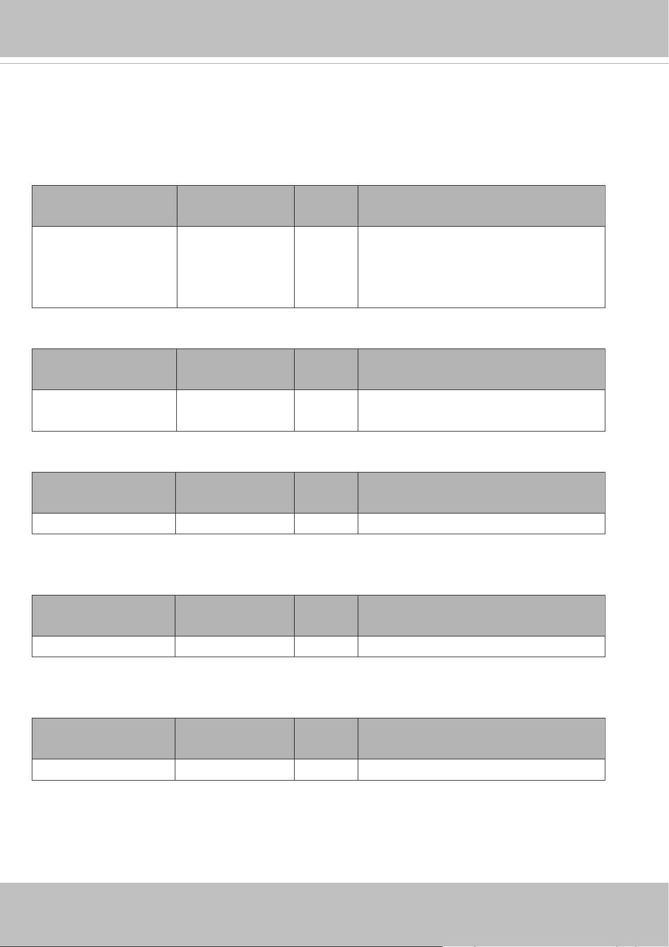
VIVOTEK
User's Manual - 321
7.45 Lens configuration
Group: lens for n channel products
n denotes the value of "capability_nvideoin"
(capability.image.c<0~(n-1)>.lensconfiguration.support = 1)
NAME VALUE SECURITY
(get/set)
DESCRIPTION
selected <string> 6/7 Current selected lens profile.
e.g. lens_selected=lens_default_i0, it means
choosen lens configuration is i0 lens of default
group.
Group: lens_default
NAME VALUE SECURITY
(get/set)
DESCRIPTION
totalnumbers 0,<positive integer> 6/7 Totoal support number of the default lens
profiles
Group: lens_user
NAME VALUE SECURITY
(get/set)
DESCRIPTION
totalnumbers 0,<positive integer> 6/7 Totoal support number of the user lens profiles
Group: lens_default_i<0~(n-1)>
n denotes the value of "lens_default_totalnumbers"
NAME VALUE SECURITY
(get/set)
DESCRIPTION
name <string> 6/7 Default lens name
Group: lens_user_i<0~(n-1)>
n denotes the value of "lens_user_totalnumbers"
NAME VALUE SECURITY
(get/set)
DESCRIPTION
name <string> 6/7 User-defined lens name

VIVOTEK
322 - User's Manual
7.46 Fisheye info
Group: fisheyeinfo
(capability.fisheye > 0)
NAME VALUE SECURITY
(get/set)
DESCRIPTION
revisedcenteraxis <coordinate> 6/7 The actual center axis coordinate
radius 0, <positive
integer>
6/7 The actual center radius
7.47 Fisheye local dewarp setting
Group: fisheyedewarp_c<0~(n-1)>
(capability_fisheyelocaldewarp_c<0~(n-1)> > 0)
n denotes the value of "capability_nvideoin", m denotes the value of "capability_nmediastream"
NAME VALUE SECURITY
(get/set)
DESCRIPTION
panspeed -5 ~ 5
<integer>
1/4 Pan speed of regional view
tiltspeed -5 ~ 5
<integer>
1/4 Tilt speed of regional view
zoomspeed -5 ~ 5
<integer>
1/4 Zoom speed of regional
s<0~(m-2)>_panorama_
panstart
0~359
<integer>
1/4 Initial pan position of panorama view.
(only available for 1P and 2P mode at ceiling or
floor mount)
s<0~(m-2)>_region_pan -90~359
<integer>
1/4 Pan home angle of regional view
Pan range of ceiling/floor mount is [0~359].
Pan range of wall mount is [-90~90].
s<0~(m-2)>_region_tilt -90~90
<integer>
1/4 Tilt home angle of regional view
Tilt range of ceiling/floor mount is [0~90].
Tilt range of wall mount is [-90~90].
s<0~(m-2)>_region_zoo
m
100~300
<integer>
1/4 Zoom home ratio of regional view

VIVOTEK
User's Manual - 323
7.48 PIR behavior define
Group: pir
(capability.npir > 0)
NAME VALUE SECURITY
(get/set)
DESCRIPTION
enable <boolean> 1/1 Enable/disable PIR
7.49 Auto tracking setting
Group: autotrack_c<0~(n-1)>
(capability_image_c<0~(n-1)>_autotrack_support > 0)
n denotes the value of "capability_nvideoin"
PARAMETER VALUE SECURITY
(get/set)
DESCRIPTION
objsize_type -1~2 1/4 Type of object size.
-1 : customized width and height
0 : object size = 30 x 30
1 : object size = 10 x 20
2 : object size = 10 x 10
objsize_customized_width 10~320 1/4 The minimum width of tracking target.
objsize_customized_height 10~240 1/4 The minimum height of tracking target.
sensitivity 0~2 1/4 Tracking sensitivity.
0: Low
1: Medium
2: High
7.50 Wireless
Group: wireless
(capability_network_wireless > 0)
PARAMETER VALUE SECURITY
(get/set)
DESCRIPTION
ssid string[32] 6/6 SSID for wireless lan settings.
wlmode Infra,
Adhoc
6/6 Wireless mode.
Infra: Infrastructure

VIVOTEK
324 - User's Manual
channel 1~11 or
1~13 or
10~11 or
10~13 or
1~14
6/6 A list of WLAN channels.
Countries apply their own regulations to the
allowable channels.
1~11: USA and Canada
1~13: Europe
10~11: Spain
10~13: France
1~14: Japan
* Only valid when "wireless_wlmode" is "Adhoc"
encrypt none,
wep,
wpa,
wpa2
6/6 Encryption method:
none: NONE,
wep: WEP,
wpa: WPA,
wpa2: WPA2PSK
authmode OPEN, SHARED 6/6 Authentication mode.
* Only valid when "wireless_encrypt" is "wep"
keylength 64, 128 6/6 Key length in bits.
* Only valid when "wireless_encrypt" is "wep"
keyformat HEX, ASCII 6/6 Key1 ~ key4 presentation format.
* Only valid when "wireless_encrypt" is "wep"
keyselect 1 ~ 4 6/6 Default key number.
* Only valid when "wireless_encrypt" is "wep"
key1 password [26] 6/6 WEP key1 for encryption.
* Only valid when "wireless_encrypt" is "wep"
key2 password [26] 6/6 WEP key2 for encryption.
* Only valid when "wireless_encrypt" is "wep"
key3 password [26] 6/6 WEP key3 for encryption.
* Only valid when "wireless_encrypt" is "wep"
key4 password [26] 6/6 WEP key4 for encryption.
* Only valid when "wireless_encrypt" is "wep"
algorithm AES, TKIP 6/6 Algorithm
* Only valid when "wireless_encrypt" is "wpa" or
"wpa2"
presharedkey password [64] 6/6 WPA/WPA2PSK mode pre-shared key.
* Only valid when "wireless_encrypt" is "wpa" or
"wpa2"

VIVOTEK
User's Manual - 325
7.51 Shock detection
Group: shock_c<0~(n-1)> for n channel products
n denotes the value of "capability_nvideoin"
(capability_shockalarm_support > 0)
PARAMETER VALUE SECURITY
(get/set)
DESCRIPTION
alarm_enable <boolean> 4/4 Enable shock detection's alarm.
alarm_level 1~100 4/4 The value indicate the support strength level of
shock detection's alarm.
VIVOTEK
326 - User's Manual
8. Useful Functions
8.1 Drive the Digital Output
(capability.ndo > 0)
Note: This request requires Viewer privileges.
Method: GET/POST
Syntax:
http://<servername>/cgi-bin/dido/setdo.cgi?do1=<state>[&do2=<state>]
[&do3=<state>][&do4=<state>]
Where state is 0 or 1; “0” means inactive or normal state, while “1” means active or triggered state.
PARAMETER VALUE DESCRIPTION
do<num> 0, 1 0 – Inactive, normal state
1 – Active, triggered state
Example: Drive the digital output 1 to triggered state and redirect to an empty page.
http://myserver/cgi-bin/dido/setdo.cgi?do1=1
8.2 Query Status of the Digital Input(capability.ndi > 0)
Note: This request requires Viewer privileges
Method: GET/POST
Syntax:
http://<servername>/cgi-bin/dido/getdi.cgi?[di0][&di1][&di2][&di3]
If no parameter is specified, all of the digital input statuses will be returned.
Return:
HTTP/1.0 200 OK\r\n
Content-Type: text/plain\r\n
Content-Length: <length>\r\n
\r\n
[di0=<state>]\r\n
[di1=<state>]\r\n
[di2=<state>]\r\n
[di3=<state>]\r\n
where <state> can be 0 or 1.

VIVOTEK
User's Manual - 327
Example: Query the status of digital input 1 .
Request:
http://myserver/cgi-bin/dido/getdi.cgi?di1
Response:
HTTP/1.0 200 OK\r\n
Content-Type: text/plain\r\n
Content-Length: 7\r\n
\r\n
di1=1\r\n
8.3 Query Status of the Digital Output
(capability.ndo > 0)
Note: This request requires Viewer privileges
Method: GET/POST
Syntax:
http://<servername>/cgi-bin/dido/getdo.cgi?[do0][&do1][&do2][&do3]
If no parameter is specified, all the digital output statuses will be returned.
Return:
HTTP/1.0 200 OK\r\n
Content-Type: text/plain\r\n
Content-Length: <length>\r\n
\r\n
[do0=<state>]\r\n
[do1=<state>]\r\n
[do2=<state>]\r\n
[do3=<state>]\r\n
where <state> can be 0 or 1.
Example: Query the status of digital output 1.
Request:
http://myserver/cgi-bin/dido/getdo.cgi?do1
Response:
HTTP/1.0 200 OK\r\n
Content-Type: text/plain\r\n
Content-Length: 7\r\n
VIVOTEK
328 - User's Manual
\r\n
do1=1\r\n
8.4 Capture Single Snapshot
Note: This request requires Normal User privileges.
Method: GET/POST
Syntax:
http://<servername>/cgi-bin/viewer/video.jpg?[channel=<value>][&resolution=<value>]
[&quality=<value>][&streamid=<value>]
If the user requests a size larger than all stream settings on the server, this request will fail.
PARAMETER VALUE DESCRIPTION
channel 0~(capability_nvideoin -1) The channel number of the video source.
resolution Available options are list in
"capability_videoin_c<0~(n-1)>_resolution".
Besides, available options is referred to
"capability_videoin_c<0~(n-1)>_maxresolution"
and
"capability_videoin_c<0~(n-1)>_minresolution"
The resolution of the image.
quality 1~5 The quality of the image.
streamid 0~( capability_nmediastream -1) The stream number.
The server will return the most up-to-date snapshot of the selected channel and stream in JPEG format. The size
and quality of the image will be set according to the video settings on the server.
Return:
HTTP/1.0 200 OK\r\n
Content-Type: image/jpeg\r\n
[Content-Length: <image size>\r\n]
<binary JPEG image data>

VIVOTEK
User's Manual - 329
8.5 Account Management
Note: This request requires Administrator privileges.
Method: POST
Syntax:
http://<servername>/cgi-bin/admin/editaccount.cgi
?
method=<value>&username=<name>[&userpass=<value>][&privilege=<value>]
[&privilege=<value>][&return=<return page>]
PARAMETER VALUE DESCRIPTION
method add Add an account to the server. When using this method, the“username”
field is necessary. It will use the default value of other fields if not
specified.
delete Remove an account from the server. When using this method, the
“username” field is necessary, and others are ignored.
edit Modify the account password and privilege. When using this method,
the“username” field is necessary, and other fields are optional. If not
specified, it will keep the original settings.
username <name> The name of the user to add, delete, or edit.
userpass <value> The password of the new user to add or that of the old user to modify.
The default value is an empty string.
privilege view The privilege of the user to add or to modify.
“view”: Viewer privilege.
“operator”: Operator privilege.
“admin”: Administrator privilege.
operator
admin
return <return page> Redirect to the page <return page> after the parameter is assigned.
The <return page> should be the relative path according to the root of
camera. If you omit this parameter, it will redirect to an empty page.
* If the <return page> is invalid path, it will ignore this parameter.
VIVOTEK
330 - User's Manual
8.6 System Logs
Note: This request require Administrator privileges.
Method: GET/POST
Syntax:
http://<servername>/cgi-bin/admin/syslog.cgi
Server will return the most up-to-date system log.
Return:
HTTP/1.0 200 OK\r\n
Content-Type: text/plain\r\n
Content-Length: <syslog length>\r\n
\r\n
<system log information>\r\n
8.7 Upgrade Firmware
Note: This request requires Administrator privileges.
Method: POST
Syntax:
http://<servername>/cgi-bin/admin/upgrade.cgi
Post data:
fimage=<file name>[&return=<return page>]\r\n
\r\n
<multipart encoded form data>
Server will accept the file named <file name> to upgradethe firmware and return with <return page> if indicated.

VIVOTEK
User's Manual - 331
8.8 ePTZ Camera Control (capability.eptz > 0 and
capability_fisheye = 0)
Note: This request requires camctrl privileges.
Method: GET/POST
Syntax:
http://<servername>/cgi-bin/camctrl/eCamCtrl.cgi?channel=<value>&stream=<value>
[&move=<value>] – Move home, up, down, left, right
[&auto=<value>] – Auto pan, patrol
[&zoom=<value>] –Zoom in, out
[&zooming=<value>&zs=<value>] –Zoom without stopping, used for joystick
[&x=<value>&y=<value>&w=<value>&h=<value>&resolution=<value>] - Zoom in, out on a specific area
[&vx=<value>&vy=<value>&vs=<value>] – Shift without stopping, used for joystick
[&x=<value>&y=<value>&videosize=<value>&resolution=<value>&stretch=<value>] –Click on image
(Move the center of image to the coordination (x,y) based on resolution or videosize.)
[ [&speedpan=<value>][&speedtilt=<value>][&speedzoom=<value>][&speedapp=<value>] ] – Set speeds
[&return=<return page>]
Example:
http://myserver/cgi-bin/camctrl/eCamCtrl.cgi?channel=0&stream=0&move=right
http://myserver/cgi-bin/camctrl/eCamCtrl.cgi?channel=0&stream=1&vx=2&vy=2&vz=2
http://myserver/cgi-bin/camctrl/eCamCtrl.cgi?channel=0&stream=1&x=100&y=100&
videosize=640x480&resolution=640x480&stretch=0
In zoom operation, there are two ways to control it, scale zoom and area zoom.
1. [Scale zoom]: contains two control method, relative movement and continuous movement
a. relative movement -
If you trigger a relative movement, it will only zoom certain ratio and stop by itself.
http://IPAddr/cgi-bin/camctrl/eCamCtrl.cgi?stream=0&zoom=tele
http://IPAddr/cgi-bin/camctrl/eCamCtrl.cgi?stream=0&zoom=wide
The zoom ratio to move by relative movement is according to the setting of speedzoom [-5~5].
http://IPAddr/cgi-bin/camctrl/eCamCtrl.cgi?stream=0&speedzoom=5
b. continuous movement -
If you trigger a continuous movement, you have to handle the stop time by yourself.
A continuous movement is convenient to integrate a joystick control.
http://IPAddr/cgi-bin/camctrl/eCamCtrl.cgi?stream=0&zooming=tele&zs=1
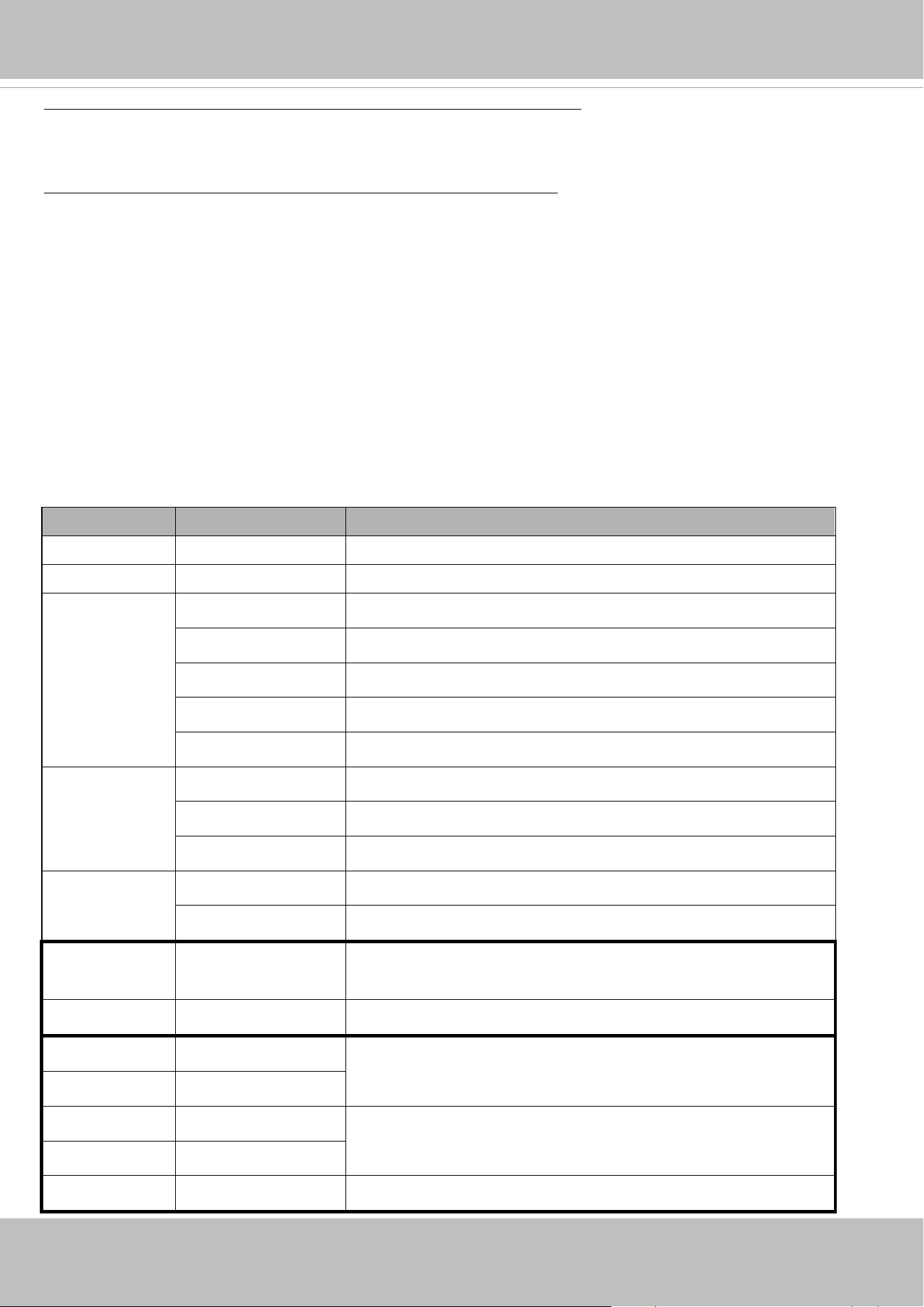
VIVOTEK
332 - User's Manual
http://IPAddr/cgi-bin/camctrl/eCamCtrl.cgi?stream=0&zooming=wide&zs=5
zooming is used to indicate the moving direction, and zs is used to indicate the speed.
To stop a continuous movement, you have to use the command as below:
http://IPAddr/cgi-bin/camctrl/eCamCtrl.cgi?stream=0&zoom=stop&zs=0
2. [Area zoom]: it means to zoom in on a specific area, here is an example for a directly moving
[x, y] is the desired coordinate, and it will be the center after movement
[w, h] is the scaled area size
[resolution] is the base range of this coordinate system
The example shows [w, h] = [864, 488], which means to zoom in to ratio x2.2 based on [1920x1080].
Pay attention to that [x, y, w, h] are essential parameters in an area zoom case, and the stream index is counted
from 0 as the first stream.
http://IPAddr/cgi-bin/camctrl/eCamCtrl.cgi?channel=0&stream=0&x=912&y=297&w=864&h=488&resolution=
1920x1080
PARAMETER VALUE DESCRIPTION
channel <0~(n-1)> Channel of video source.
stream <0~(m-1)> Stream.
move home Move to home ROI.
up Move up.
down Move down.
left Move left.
right Move right.
auto pan Auto pan.
patrol Auto patrol.
stop Stop auto pan/patrol.
zoom wide Zoom larger view with current speed.
tele Zoom further with current speed.
zooming wide or tele Zoom without stopping for larger view or further view with zs speed,
used for joystick control.
zs 0 ~ 6 Set the speed of zooming, “0” means stop.
x <integer> The desired coordinate, and it will be the center after movement
y <integer>
w <integer> The scaled area size
h <integer>
resolution <window size> The resolution of streaming.

VIVOTEK
User's Manual - 333
vx <integer> The direction of movement, used for joystick control.
vy <integer>
vs 0 ~ 7 Set the speed of movement, “0” means stop.
x <integer> x-coordinate clicked by user.
It will be the x-coordinate of center after movement.
y <integer> y-coordinate clicked by user.
It will be the y-coordinate of center after movement.
videosize <window size> The size of plug-in (ActiveX)window in web page
resolution <window size> The resolution of streaming.
stretch <boolean> 0 indicates that it usesresolution(streaming size) as the range of the
coordinate system.
1 indicates that it usesvideosize(plug-in size) as the range of the
coordinate system.
speedpan -5 ~ 5 Set the pan speed.
speedtilt -5 ~ 5 Set the tilt speed.
speedzoom -5 ~ 5 Set the zoom speed.
speedapp 1 ~ 5 Set the auto pan/patrol speed.
return <return page> Redirect to the page <return page> after the parameter is assigned.
The <return page> should be the relative path according to the root of
camera. If you omit this parameter, it will redirect to an empty page.
* If the <return page> is invalid path, it will ignore this parameter.
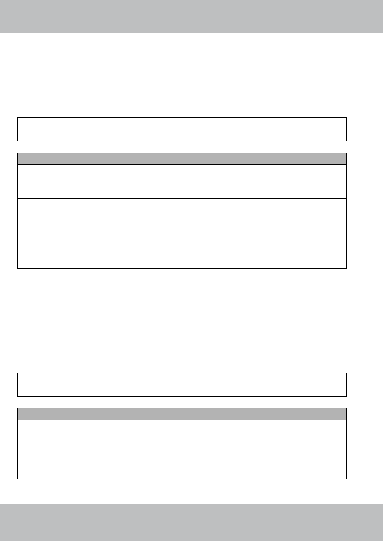
VIVOTEK
334 - User's Manual
8.9 ePTZ Recall (capability.eptz > 0 and capability_fisheye = 0)
Note: This request requires camctrl privileges.
Method: GET/POST
Syntax:
http://<servername>/cgi-bin/camctrl/eRecall.cgi?channel=<value>&stream=<value>&
recall=<value>[&return=<return page>]
PARAMETER VALUE DESCRIPTION
channel <0~(n-1)> Channel of the video source.
stream <0~(m-1)> Stream.
recall Text string less than 40
characters
One of the present positions to recall.
return <return page> Redirect to the page <return page> after the parameter is assigned.
The <return page> should be the relative path according to the root of
camera. If you omit this parameter, it will redirect to an empty page.
* If the <return page> is invalid path, it will ignore this parameter.
8.10 ePTZ Preset Locations(capability.eptz > 0 and
capability_fisheye = 0)
Note: This request requires Operator privileges.
Method: GET/POST
Syntax:
http://<servername>/cgi-bin/operator/ePreset.cgi?channel=<value>&stream=<value>
[&addpos=<value>][&delpos=<value>][&return=<return page>]
PARAMETER VALUE DESCRIPTION
channel <0~(n-1)> Channel of the video source.
stream <0~(m-1)> Stream.
addpos <Text string less than
40 characters>
Add one preset location to the preset list.
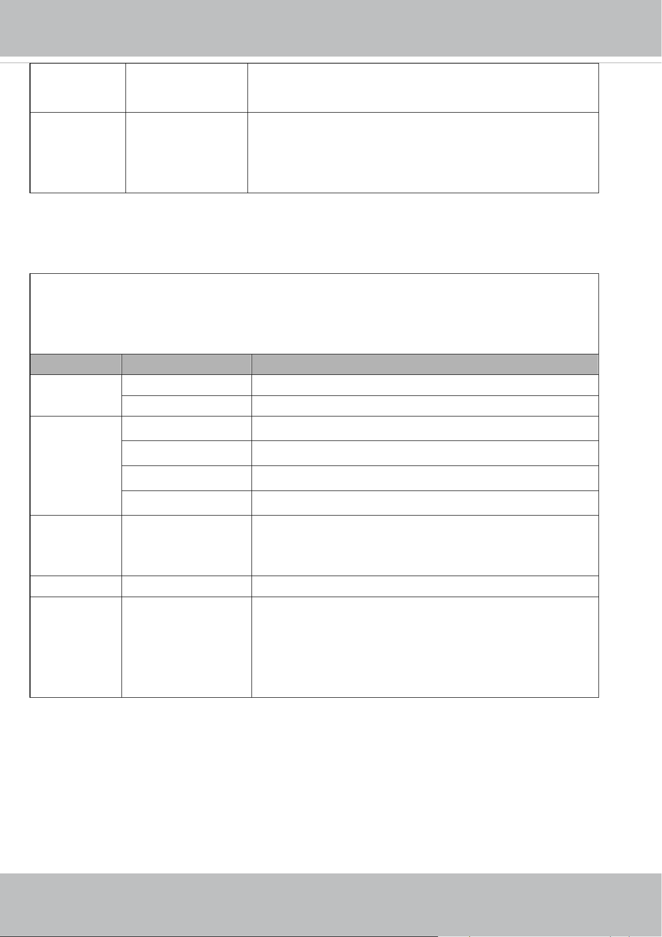
VIVOTEK
User's Manual - 335
delpos <Text string less than
40 characters>
Delete preset location from the preset list.
return <return page> Redirect to the page <return page> after the parameter is assigned.
The <return page> should be the relative path according to the root of
camera. If you omit this parameter, it will redirect to an empty page.
* If the <return page> is invalid path, it will ignore this parameter.
8.11 IP Filtering for ONVIF
Syntax:<product dependent>
http://<servername>/cgi-bin/admin/ipfilter.cgi?type[=<value>]
http://<servername>/cgi-bin/admin/ipfilter.cgi?method=add<v4/v6>&ip=<ipaddress>[&index=<value>][&ret
urn=<return page>]
http://<servername>/cgi-bin/admin/ipfilter.cgi?method=del<v4/v6>&index=<value>[&return=<return page>]
PARAMETER VALUE DESCRIPTION
type NULL Get IP filter type
allow, deny Set IP filter type
method addv4 Add IPv4 address into access list.
addv6 Add IPv6 address into access list.
delv4 Delete IPv4 address from access list.
delv6 Delete IPv6 address from access list.
ip <IP address> Single address: <IP address>
Network address: <IP address / network mask>
Range address:<start IP address - end IP address>
index <value> The start position to add or to delete.
return <return page> Redirect to the page <return page> after the parameter is assigned.
The <return page> should be the relative path according to the root
of camera. If you omit this parameter, it will redirect to an empty
page.
* If the <return page> is invalid path, it will ignore this parameter.

VIVOTEK
336 - User's Manual
8.12 UART HTTP Tunnel Channel (capability.nuart > 0)
Note: This request requires Operator privileges.
Method: GET and POST
Syntax:
http://<servername>/cgi-bin/operator/uartchannel.cgi?[channel=<value>]
-------------------------------------------------------------------------
GET /cgi-bin/operator/uartchannel.cgi?[channel=<value>]
x-sessioncookie: string[22]
accept: application/x-vvtk-tunnelled
pragma: no-cache
cache-control: no-cache
-------------------------------------------------------------------------
POST /cgi-bin/operator/uartchannel.cgi
x-sessioncookie: string[22]
content-type: application/x-vvtk-tunnelled
pragma : no-cache
cache-control : no-cache
content-length: 32767
expires: Sun, 9 Jam 1972 00:00:00 GMT
User must use GET and POST to establish two channels for downstream and upstream. The x-sessioncookie in GET
and POST should be the same to be recognized as a pair for one session. The contents of upstream should be
base64 encoded to be able to pass through a proxy server.
This channel will help to transfer the raw data of UART over the network.
Please see UART tunnel spec for detail information
PARAMETER VALUE DESCRIPTION
channel 0 ~ (n-1) The channel number of UART.

VIVOTEK
User's Manual - 337
8.13 Event/Control HTTP Tunnel Channel (capability.
evctrlchannel > 0)
Note: This request requires Administrator privileges.
Method: GET and POST
Syntax:
http://<servername>/cgi-bin/admin/ctrlevent.cgi
-------------------------------------------------------------------------
GET /cgi-bin/admin/ctrlevent.cgi
x-sessioncookie: string[22]
accept: application/x-vvtk-tunnelled
pragma: no-cache
cache-control: no-cache
-------------------------------------------------------------------------
POST /cgi-bin/admin/ ctrlevent.cgi
x-sessioncookie: string[22]
content-type: application/x-vvtk-tunnelled
pragma : no-cache
cache-control : no-cache
content-length: 32767
expires: Sun, 9 Jam 1972 00:00:00 GMT
User must use GET and POST to establish two channels for downstream and upstream. The x-sessioncookie in GET
and POST should be the same to be recognized as a pair for one session. The contents of upstream should be
base64 encoded to be able to pass through the proxy server.
This channel will help perform real-time event subscription and notification as well as camera control more
efficiently. The event and control formats are described in another document.
See Event/control tunnel spec for detail information

VIVOTEK
338 - User's Manual
8.14 Get SDP of Streams
Note: This request requires Viewer access privileges.
Method: GET/POST
Syntax:
http://<servername>/<network_rtsp_s<0~m-1>_accessname>
“m” is the stream number.
“network_accessname_<0~(m-1)>” is the accessname for stream “1” to stream “m”. Please refer to the
“subgroup of network: rtsp” for setting the accessname of SDP.
You can get the SDP by HTTP GET.
When using scalable multicast, Get SDP file which contains the multicast information via HTTP.
8.15 Open the Network Stream
Note: This request requires Viewer access privileges.
Syntax:
For HTTP push server (MJPEG):
http://<servername>/<network_http_s<0~m-1>_accessname>
For RTSP (MP4), the user needs to input theURL below into an RTSP compatible player.
rtsp://<servername>/<network_rtsp_s<0~m-1>_accessname>
“m” is the stream number.
For details on streaming protocol, please refer to the “control signaling” and “data format” documents.

VIVOTEK
User's Manual - 339
8.16 Senddata (capability.nuart > 0)
Note: This request requires Viewer privileges.
Method: GET/POST
Syntax:
http://<servername>/cgi-bin/viewer/senddata.cgi?
[com=<value>][&data=<value>][&flush=<value>] [&wait=<value>] [&read=<value>]
PARAMETER VALUE DESCRIPTION
com 1 ~ <max. com port
number>
The target COM/RS485 port number.
data <hex decimal
data>[,<hex decimal
data>]
The <hex decimal data> is a series of digits from 0 ~ 9, A ~ F. Each
comma separates the commands by 200 milliseconds.
flush yes,no yes: Receive data buffer of the COM port will be cleared before read.
no: Do not clear the receive data buffer.
wait 1 ~ 65535 Wait time in milliseconds before read data.
read 1 ~ 128 The data length in bytes to read. The read data will be in the return
page.
Return:
HTTP/1.0 200 OK\r\n
Content-Type: text/plain\r\n
Content-Length: <system information length>\r\n
\r\n
<hex decimal data>\r\n
Where hexadecimal data is digits from 0 ~ 9, A ~ F.

VIVOTEK
340 - User's Manual
8.17 Storage managements (capability.storage.dbenabled > 0)
Note: This request requires administrator privileges.
Method: GET and POST
Syntax:
http://<servername>/cgi-bin/admin/lsctrl.cgi?cmd=<cmd_type>[&<parameter>=<value>…]
The commands usage and their input arguments are as follows.
PARAMETER VALUE DESCRIPTION
cmd_type <string> Required.
Command to be executed, including search, insert, delete, update,
and queryStatus.
Command: search
PARAMETER VALUE DESCRIPTION
label <integer primary key> Optional.
The integer primary key column will automatically be assigned a
unique integer.
triggerType <text> Optional.
Indicate the event trigger type.
Please embrace your input value with single quotes.
Ex. mediaType=’motion’
Support trigger types are product dependent.
mediaType <text> Optional.
Indicate the file media type.
Please embrace your input value with single quotes.
Ex. mediaType=’videoclip’
Support trigger types are product dependent.
destPath <text> Optional.
Indicate the file location in camera.
Please embrace your input value with single quotes.
Ex. destPath =’/mnt/auto/CF/NCMF/abc.mp4’
resolution <text> Optional.
Indicate the media file resolution.
Please embrace your input value with single quotes.
Ex. resolution=’800x600’
isLocked <boolean> Optional.

VIVOTEK
User's Manual - 341
Indicate if the file is locked or not.
0: file is not locked.
1: file is locked.
A locked file would not be removed from UI or cyclic storage.
triggerTime <text> Optional.
Indicate the event trigger time. (not the file created time)
Format is “YYYY-MM-DD HH:MM:SS”
Please embrace your input value with single quotes.
Ex. triggerTime=’2008-01-01 00:00:00’
If you want to search for a time period, please apply “TO”
operation.
Ex. triggerTime=’2008-01-01 00:00:00’+TO+’2008-01-01
23:59:59’ is to search for records from the start of Jan 1
st
2008to
the end of Jan 1
st
2008.
limit <positive integer> Optional.
Limit the maximum number of returned search records.
offset <positive integer> Optional.
Specifies how many rows to skip at the beginning of the matched
records.
Note that the offset keyword is used after limit keyword.
To increase the flexibility of search command, you may use “OR” connectors for logical “OR” search operations.
Moreover, to search for a specific time period, you can use “TO” connector.
Ex. To search records triggered by motion or di or sequential and also triggered between 2008-01-01 00:00:00 and
2008-01-01 23:59:59.
http://<servername>/cgi-bin/admin/lsctrl.cgi?cmd=search&triggerType=’motion’+OR+’di’+OR+’seq’&triggerTi
me=’2008-01-01 00:00:00’+TO+’2008-01-01 23:59:59’
Command: delete
PARAMETER VALUE DESCRIPTION
label <integer primary key> Required.
Identify the designated record.
Ex. label=1
Ex. Delete records whose key numbers are 1, 4, and 8.
http://<servername>/cgi-bin/admin/lsctrl.cgi?cmd=delete&label=1&label=4&label=8
Command: update
PARAMETER VALUE DESCRIPTION
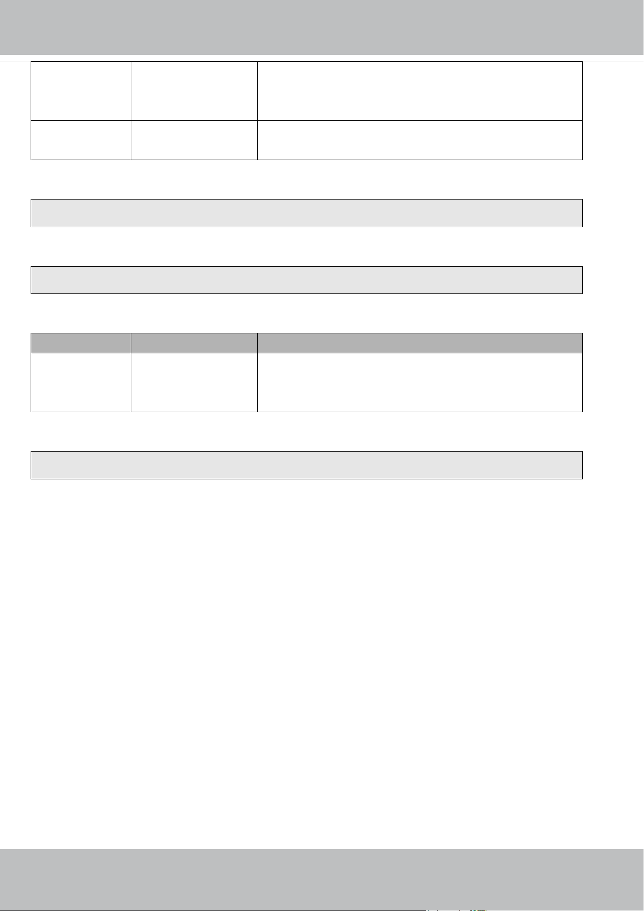
VIVOTEK
342 - User's Manual
label <integer primary key> Required.
Identify the designated record.
Ex. label=1
isLocked <boolean> Required.
Indicate if the file is locked or not.
Ex. Update records whose key numbers are 1 and 5 to be locked status.
http://<servername>/cgi-bin/admin/lsctrl.cgi?cmd=update&isLocked=1&label=1&label=5
Ex. Update records whose key numbers are 2 and 3 to be unlocked status.
http://<servername>/cgi-bin/admin/lsctrl.cgi?cmd=update&isLocked=0&label=2&label=3
Command: queryStatus
PARAMETER VALUE DESCRIPTION
retType xml or javascript Optional.
Ex. retype=javascript
The default return message is in XML format.
Ex. Query local storage status and call for javascript format return message.
http://<servername>/cgi-bin/admin/lsctrl.cgi?cmd=queryStatus&retType=javascript

VIVOTEK
User's Manual - 343
8.18 Virtual input (capability.nvi > 0)
Note: Change virtual input (manual trigger) status.
Method: GET
Syntax:
http://<servername>/cgi-bin/admin/setvi.cgi?vi0=<value>[&vi1=<value>][&vi2=<value>]
[&return=<return page>]
PARAMETER VALUE DESCRIPTION
vi<num> state[(duration)nstate]
Where "state" is 0, 1. “0”
means inactive or normal
state while “1” means
active or triggered state.
Where "nstate" is next
state after duration.
Ex: vi0=1
Setting virtual input 0 to trigger state
Ex: vi0=0(200)1
Setting virtual input 0 to normal state, waiting 200
milliseconds, setting it to trigger state.
Note that when the virtual input is waiting for next state, it
cannot accept new requests.
return <return page> Redirect to the page <return page> after the parameter is
assigned. The <return page> should be the relative path
according to the root of camera. If you omit this parameter, it
will redirect to an empty page.
* If the <return page> is invalid path, it will ignore this
parameter.
Return Code Description
200 The request is successfully executed.
400 The request cannot be assigned, ex. incorrect parameters.
Examples:
setvi.cgi?vi0=0(10000)1(15000)0(20000)1
No multiple duration.
setvi.cgi?vi3=0
VI index is out of range.
setvi.cgi?vi=1
No VI index is specified.
503 The resource is unavailable, ex. Virtual input is waiting for next state.
Examples:
setvi.cgi?
vi0=0(15000)1
setvi.cgi?vi0=1
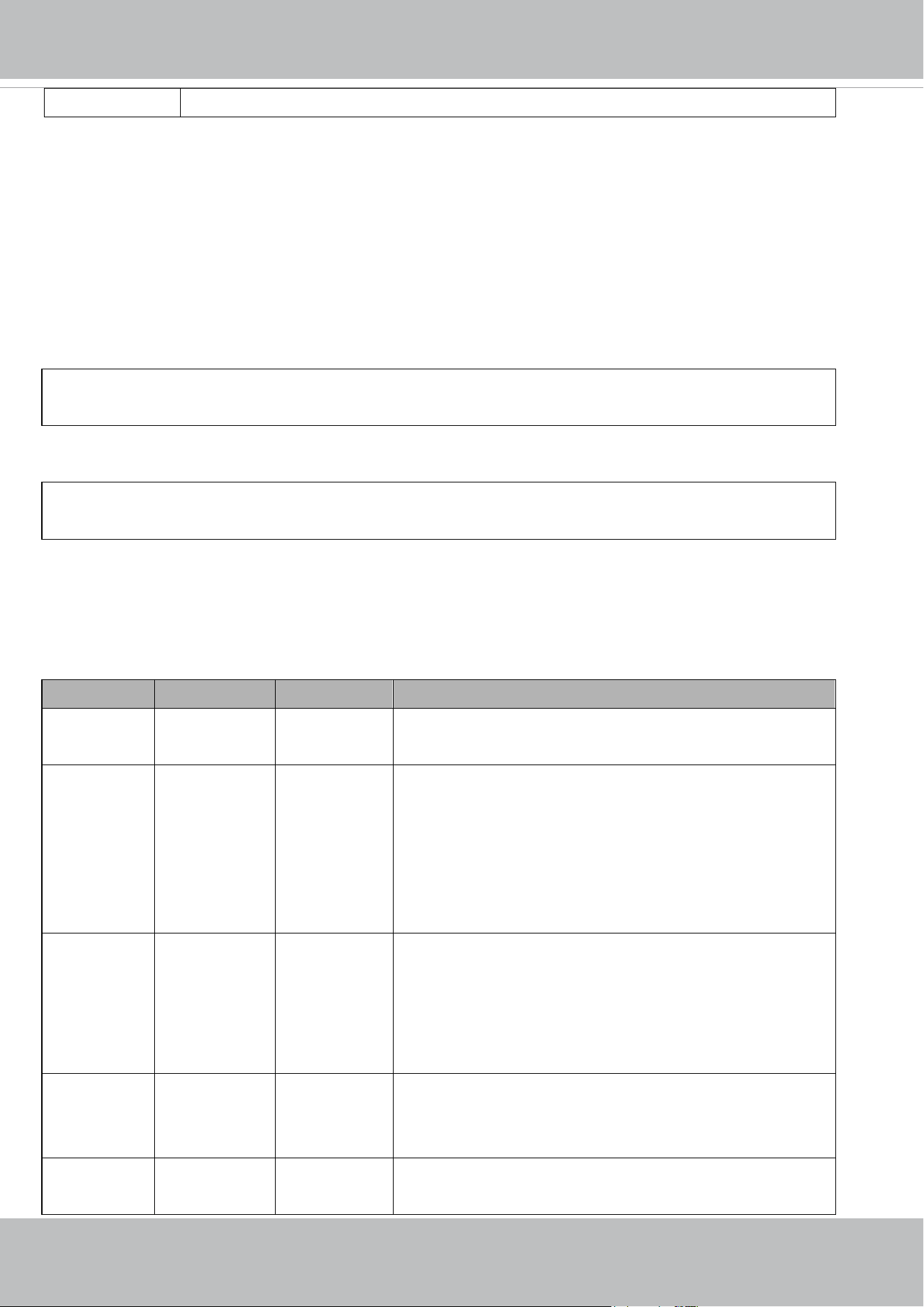
VIVOTEK
344 - User's Manual
Request 2 will not be accepted during the execution time(15 seconds).
8.19 Open Timeshift Stream (capability.timeshift > 0,
timeshift_enable=1, timeshift_c<n>_s<m>_allow=1)
Note: This request requires Viewer access privileges.
Syntax:
For HTTP push server (MJPEG):
http://<servername>/<network_http_s<m>_accessname>?maxsft=<value>[&tsmode=<value>&reftime=<v
alue>&forcechk&minsft=<value>]
For RTSP (MP4 and H264), the user needs to input theURL below into an RTSP compatible player.
rtsp://<servername>/<network_rtsp_s<m>_accessname>?maxsft=<value>[&tsmode=<value>&reftime=<va
lue>&forcechk&minsft=<value>]
“n” is the channel index.
“m” is the timeshift stream index.
For details on timeshift stream, please refer to the “TimeshiftCaching” documents.
PARAMETER VALUE DEFAULT DESCRIPTION
maxsft <positive
integer>
0 Request cached stream at most how many seconds ago.
tsmode normal,
adaptive
normal Streaming mode:
normal => Full FPS all the time.
adaptive => Default send only I-frame for MP4 and H.264, and
send 1 FPS for MJPEG. If DI or motion window are triggered, the
streaming is changed to send full FPS for 10 seconds.
(*Note: this parameter also works on non-timeshift streams.)
reftime mm:ss The time
camera receives
the request.
Reference time for maxsft and minsft.
(This provides more precise time control to eliminate the
inaccuracy due to network latency.)
Ex: Request the streaming from 12:20
rtsp://10.0.0.1/live.sdp?maxsft=10&reftime=12:30
forcechk N/A N/A Check if the requested stream enables timeshift, feature and
if minsft is achievable.
If false, return “415 Unsupported Media Type”.
minsft <positive
integer>
0 How many seconds of cached stream client can accept at least.
(Used by forcechk)

VIVOTEK
User's Manual - 345
Return Code Description
400 Bad Request Request is rejected because some parameter values are illegal.
415 Unsupported Media Type Returned, if forcechk appears,when minsft is not achievable or the timeshift
feature of the target stream is not enabled.
VIVOTEK
346 - User's Manual
8.20 RemoteFocus
(capability_image_c<0~(n-1)>_remotefocus=1)
Note: This request requires Administrator privileges.
Method: GET/POST
Syntax:
http://<servername>/cgi-bin/admin/remotefocus.cgi?function=<value>[&direction=<value>]
[&position=<value>][&steps=<value>][&iris]
PARAMETER VALUE DESCRIPTION

VIVOTEK
User's Manual - 347
function zoom,
focus,
auto,
scan,
stop,
positioning,
getstatus
Function type
zoom - Move focus motor
focus – Move focus motor
auto – Perform auto focus
scan – Perform focus scan
stop – Stop current operation
positioning – Position the motors
getstatus–Information of motors, return value as below:
remote_focus_zoom_motor_max: Maximum steps of zoom motor
remote_focus_focus_motor_max: Maximum steps of focus motor
remote_focus_zoom_motor_start: Start point of zoom motor
remote_focus_zoom_motor_end: End point of zoom motor
remote_focus_focus_motor_start: Start point of effective focal
length
remote_focus_focus_motor_end: End point of effective focal
length
remote_focus_zoom_motor: Current position of zoom motor
remote_focus_focus_motor: Current position of focus motor
remote_focus_zoom_enable: Current function of zoom motor
remote_focus_focus_enable: Current function of focus motor
remote_focus_iris_open: The current status of iris. 0: irisenable, 1:
irisopen
Current function of zoom/focus motor, return value as below:
0: no service
1: zooming
2. focusing
3: auto focus
4: focus scan
5: positioning (both zoom motor and focus motor)
12: reset focus
direction direct,
forward,
backward
Motor’s moving direction.
It works only if function= zoom | focus.
position 0~<motor_max> Motor’s position.
It works only if function=zoom | focus and direction=direct.
<motor_max> is refer to remote_focus_focus_motor_max or
remote_focus_zoom_motor_max which replied from
"function=getstatus"

VIVOTEK
348 - User's Manual
steps 1 ~ <motor_max> Motor’s moving steps.
It works only if function=zoom | focus and direction=forward |
backward.
<motor_max> is refer to remote_focus_focus_motor_max or
remote_focus_zoom_motor_max which replied from
"function=getstatus"
* This parameter is for additional fine-tune, the value is from 1 to 30.
iris N/A Open iris or not.
It works only if function=auto | scan.

VIVOTEK
User's Manual - 349
8.21 BackFocus (capability_image_c<0~(n-1)>_remotefocus=4)
Note: This request requires Administrator privileges.
Method: GET/POST
Syntax:
http://<servername>/cgi-bin/admin/remotefocus.cgi?function=<value>[&direction=<value>]
[&position=<value>][&steps=<value>][&iris]
PARAMETER VALUE DESCRIPTION

VIVOTEK
350 - User's Manual
function focus,
auto,
scan,
stop,
positioning,
irisopen,
irisenable,
resetfocus,
getstatus
Function type
focus – Move focus motor
auto – Perform auto focus
scan – Perform focus scan
stop – Stop current operation
positioning – Position the motors
resetfocus – reset focus position to default
irisopen – Fully open iris. It will maintain this status until sending
irisenable cgi.
irisenable – leave fully open iris and return back to previous status
getstatus–Information of motors, return value as below:
remote_focus_focus_motor_max: Maximum steps of focus motor
remote_focus_focus_motor_start: Start point of effective focal
length
remote_focus_focus_motor_end: End point of effective focal
length
remote_focus_focus_motor: Current position of focus motor
remote_focus_focus_enable: Current function of focus motor
remote_focus_iris_open: The current status of iris. 0: irisenable, 1:
irisopen
Current function of zoom/focus motor, return value as below:
0: no service
1: zooming
2. focusing
3: auto focus
4: focus scan
5: positioning (both zoom motor and focus motor)
12: reset focus
direction direct,
forward,
backward
Motor’s moving direction.
It works only if function= focus.
position 0~<motor_max> Motor’s position.
It works only if function=focus and direction=direct.
<motor_max> is refer to remote_focus_focus_motor_max which
replied from "function=getstatus"

VIVOTEK
User's Manual - 351
steps 1 ~ <motor_max> Motor’s moving steps.
It works only if function=focus and direction=forward | backward.
<motor_max> is refer to remote_focus_focus_motor_max which
replied from "function=getstatus"
* This parameter is for additional fine-tune, the value is from 1 to 30.
iris N/A Open iris or not.
It works only if function=auto | scan.
8.22 Export Files
Note: This request requires Administrator privileges.
Method: GET
Syntax:
For daylight saving time configuration file:
http://<servername>/cgi-bin/admin/exportDst.cgi
For language file:
http://<servername>/cgi-bin/admin/export_language.cgi?currentlanguage=<value>
PARAMETER VALUE DESCRIPTION
currentlanguage 0~20 Available language lists.
Please refer to:
system_info_language_i0 ~ system_info_language_i19
.
For setting backup file:
http://<servername>/cgi-bin/admin/export_backup.cgi?backup
VIVOTEK
352 - User's Manual
8.23 Upload Files
Note: This request requires Administrator privileges.
Method: POST
Syntax:
For daylight saving time configuration file:
http://<servername>/cgi-bin/admin/upload_dst.cgi
Post data:
filename =<file name>\r\n
\r\n
<multipart encoded form data>
For language file:
http://<servername>/cgi-bin/admin/upload_lan.cgi
Post data:
filename =<file name>\r\n
\r\n
<multipart encoded form data>
For setting backup file:
http://<servername>/cgi-bin/admin/upload_backup.cgi
Post data:
filename =<file name>\r\n
\r\n
<multipart encoded form data>
Server will accept the file named <file name> to upload this one to camera.
VIVOTEK
User's Manual - 353
8.24 Update Lens Configuration
(capability_image_c<0~(n-1)>_lensconfiguration_support > 0)
Note: This request requires Administrator privileges.
Method: GET
Syntax:
For list a name of lens currently used:
http://<servername>/cgi-bin/admin/update_lens.cgi?get_currentlens
For list all names of lens installed in camera:
http://<servername>/cgi-bin/admin/update_lens.cgi?list_lens
For choose selected lens configuration:
http://<servername>/cgi-bin/admin/update_lens.cgi?choose_lens=<value>
You need to reboot manually after you choose another lens configuration.
For choose selected lens configuration and reboot camera:
http://<servername>/cgi-bin/admin/update_lens.cgi?choose_reboot_lens=<value>
The camera will reboot after using this cgi.
For delete selected lens configuration:
http://<servername>/cgi-bin/admin/update_lens.cgi?delete_lens=<value>
PARAMETER VALUE DESCRIPTION
value <string> Available lens name.
Please refer to:
lens_default_i<0~(n-1)>_name
lens_user_i<0~(n-1)>_name
n is a positive integer.
Method: POST
Syntax:
For upload user-defined lens configuration:
http://<servername>/cgi-bin/admin/update_lens.cgi?upload_lens
Post data:
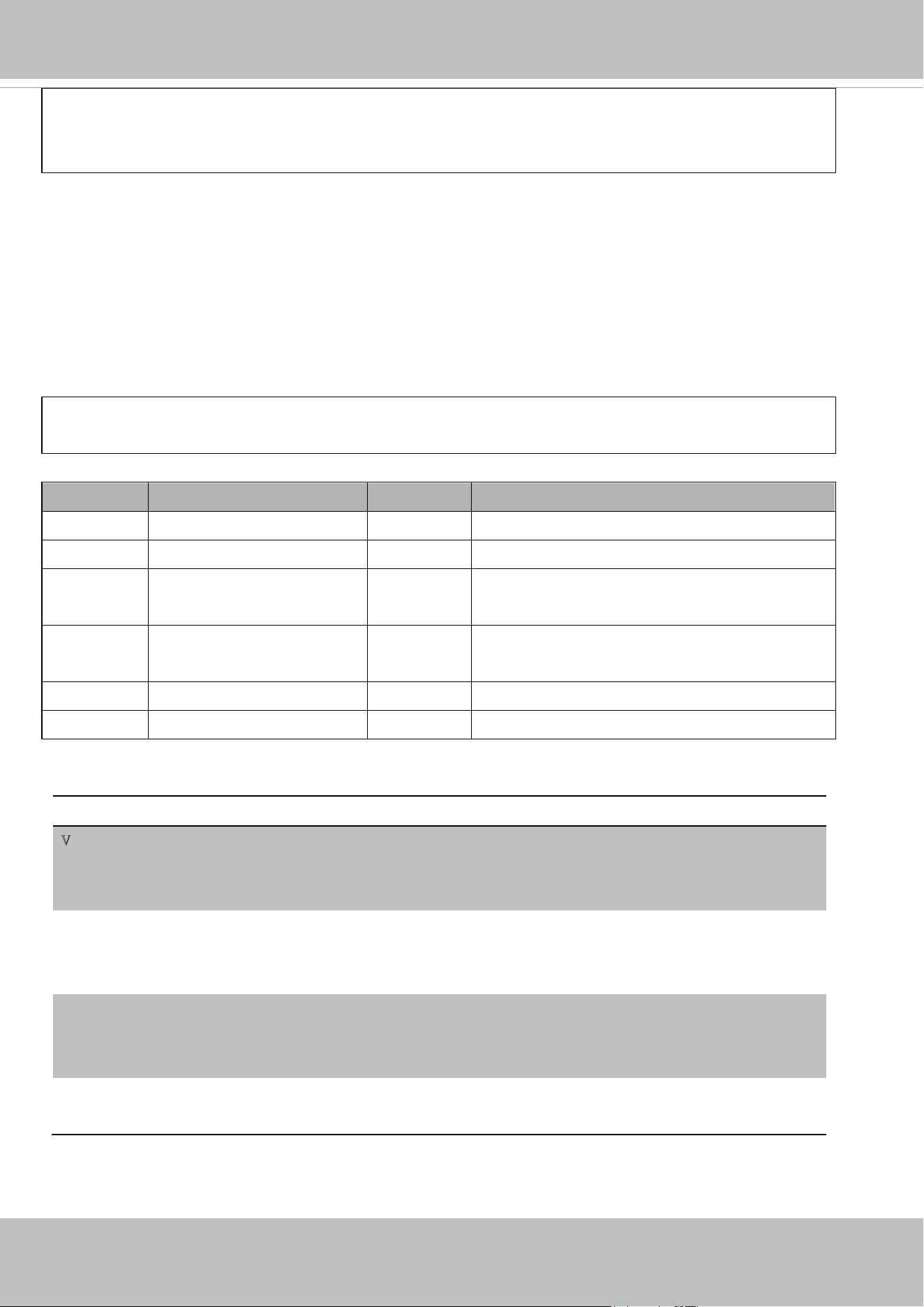
VIVOTEK
354 - User's Manual
upload_lens_profile_input = <file name>\r\n
\r\n
<multipart encoded form data>
Server will accept the file named <file name> to upload the lens profile to camera.
8.25 Media on demand
(capability.localstorage.modnum > 0)
Media on demand allows users to select and receive/watch/listen to metadata/video/audio contents on demand.
Note: This request requires Viewer access privileges.
Syntax:
rtsp://<servername>/mod.sdp?[&stime=<value>][&etime=<value>][&length =<value>][&loctime
=<value>][&file=<value>][&tsmode=<value>]
PARAMETER VALUE DEFAULT DESCRIPTION
stime <YYYYMMDD_HHMMSS.MMM> N/A Start time.
etime <YYYYMMDD_HHMMSS.MMM> N/A End time.
length <positive integer> N/A The length of media of interest.
The unit is second.
loctime <boolean> 0 Specify if start/end time is local time format.
1 for local time, 0 for UTC+0
file <string> N/A The media file to be played.
tsmode <positive integer> N/A Timeshift mode, the unit is second.
Ex.
stime etime length file Description
V
V X X
Play recordings between stime and etime
rtsp://10.10.1.2/mod.sdp?stime=20110312_040400.000&etime=
2011_0312_040510.000
V X V X
Play recordings for length seconds which start from stime
rtsp://10.10.1.2/mod.sdp?stime=20110312_040400.000&length
=120
X V V X
Play recordings for length seconds which ends at etime
rtsp://10.10.1.2/mod.sdp?etime=20110312_040400.000&length
=120
X X X V
Play file file
rtsp://10.10.1.2/mod.sdp?filename=/mnt/link0/

VIVOTEK
User's Manual - 355
8.26 Fisheye local dewarp camera control (capability.fisheye > 0
and capability.fisheyelocaldewarp.c0 > 0, only support in 1R
mode)
Note: This request requires camctrl privileges.
Method: GET/POST
Syntax:
http://<servername>/cgi-bin/camctrl/fdCamCtrl.cgi?channel=<value>&stream=<value>
[&move=<value>] – Move home, up, down, left, right
[&zoom=<value>] – Zoom wide, tele
[[&speedpan=<value>][&speedtilt=<value>][&speedzoom=<value>]] – Set speeds
[&zooming=<value>&zs=<value>] – Zoom without stopping, used for joystick
[&vx=<value>&vy=<value>&vs=<value>] – Shift without stopping, used for joystick
[&x=<value>&y=<value>&videosize=<value>&resolution=<value>&stretch=<value>] – Click on image (Move
the center of image to the coordination (x,y) based on resolution or videosize of 1O mode.)
[&return=<return page>]
Example:
http://myserver/cgi-bin/camctrl/fdCamCtrl.cgi?channel=0&stream=0&move=right
http://myserver/cgi-bin/camctrl/fdCamCtrl.cgi?channel=0&stream=0&zoom=tele
http://myserver/cgi-bin/camctrl/fdCamCtrl.cgi?channel=0&stream=0&move=top&speedtilt=-1
http://myserver/cgi-bin/camctrl/fdCamCtrl.cgi?channel=0&stream=0&zooming=tele&zs=2
http://myserver/cgi-bin/camctrl/fdCamCtrl.cgi?channel=0&stream=0&vx=5&vy=3&vs=2
http://myserver/cgi-bin/camctrl/fdCamCtrl.cgi?channel=0&stream=0&x=700&y=700&videosize=1920x1920&r
esolution=1920x1920&stretch=1
PARAMETER VALUE DESCRIPTION
channel <0~(n-1)> Channel of video source.
stream <0~(m-1)> Stream.
move home Move to home position.
up Move up.
down Move down.
left Move left.
right Move right.

VIVOTEK
356 - User's Manual
zoom wide Zoom larger view with current speed.
tele Zoom further with current speed.
speedpan -5 ~ 5 Set the pan speed of current command.
speedtilt -5 ~ 5 Set the tilt speed of current command.
speedzoom -5 ~ 5 Set the zoom speed of current command.
zooming wide or tele Zoom without stopping for larger view or further view with zs speed,
used for joystick control.
zs 0 ~ 6 Set the speed of zooming, “0” means stop.
vx -6 ~ 6 The direction of movement, used for joystick control.
vy -6 ~ 6
vs 0 ~ 7 Set the speed of movement, “0” means stop.
x <integer> x-coordinate clicked by user.
It will be the x-coordinate of center after movement.
y <integer> y-coordinate clicked by user.
It will be the y-coordinate of center after movement.
videosize <window size> The size of plug-in (ActiveX) window in web page of 1O content.
resolution <window size> The resolution of streaming of 1O content.
stretch <boolean> 0 indicates that it uses resolution (streaming size) as the range of
the coordinate system.
1 indicates that it uses videosize (plug-in size) as the range of the
coordinate system.
return <return page> Redirect to the page <return page> after the parameter is assigned.
The <return page> should be the relative path according to the root of
camera. If you omit this parameter, it will redirect to an empty page.
* If the <return page> is invalid path, it will ignore this parameter.
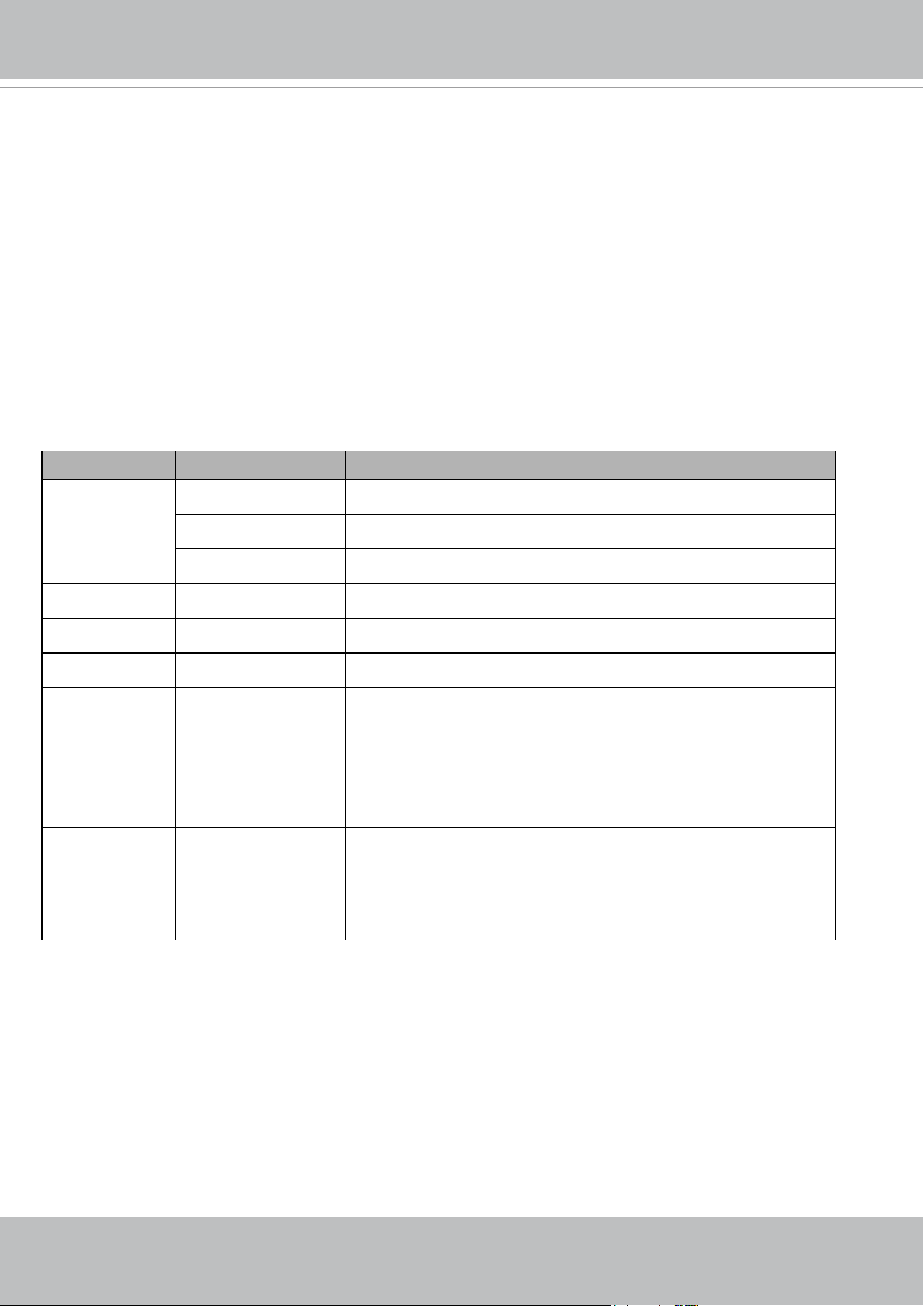
VIVOTEK
User's Manual - 357
8.27 3D Privacy Mask
(capability_image_c<0~(n-1)>_privacymask_wintype =
3Drectangle) n denotes the value of "capability_nvideoin"
Note: This request requires admin user privilege
Method: GET/POST
Syntax:
http://<servername>/cgi-bin/admin/setpm3d.cgi?method=<value>&maskname=<value>&[maskheight=<valu
e>&maskwidth=<value>&videosize=<value>&return=<return page>]
PARAMETER VALUE DESCRIPTION
method add Add a 3D privacy mask at current location
delete Delete a 3D privacy mask
edit Edit a 3D privacy mask
maskname string[40] 3D privacy mask name
maskheight integer 3D privacy mask height
maskwidth integer 3D privacy mask width
videosize <window size> Optimal.
The size of plug-in (ActiveX) window in web page is the size of the
privacy window size. This field is not necessary, it will use the default
value if not specified. 320x180 for 16:9 resolution and 320x240 for
4:3 resolution.
return <return page> Redirect to the page <return page> after the parameter is assigned.
The <return page> should be the relative path according to the root of
camera. If you omit this parameter, it will redirect to an empty page.
* If the <return page> is invalid path, it will ignore this parameter.

VIVOTEK
358 - User's Manual
8.28 Camera Control
(capability_camctrl_c<0~(n-1)>_zoommodule = 1)
Note: This request requires Viewer privileges.
Method: GET/POST
Syntax: (for control API)
http://<servername>/cgi-bin/camctrl/camctrl.cgi?[channel=<value>][&camid=<value>]
[&move=<value>] – Move home, up, down, left, right
[&focus=<value>] – Focus operation
[&zoom=<value>] – Zoom in, out
[&zooming=<value>&zs=<value>] – Zoom without stopping, used for joystick
[&vx=<value>&vy=<value>&vs=<value>] – Shift without stopping, used for joystick
[&x=<value>&y=<value>&videosize=<value>&resolution=<value>&stretch=<value>] – Click on image
(Move the center of image to the coordination (x,y) based on resolution or videosize.)
[ [&speedpan=<value>][&speedtilt=<value>][&speedzoom=<value>][&speedapp=<value>][&speedlink=<val
ue>] ] – Set speeds
[&return=<return page>]
Example:
http://myserver/cgi-bin/camctrl/camctrl.cgi?channel=0&camid=1&move=right
http://myserver/cgi-bin/camctrl/camctrl.cgi?channel=0&camid=1&zoom=tele
http://myserver/cgi-bin/camctrl/camctrl.cgi?channel=0&camid=1&x=300&y=200&resolution=704x480&videosi
ze=704x480&strech=1
Example: (set the ptz preset with focus mode)
* We support this function when the version number of the PTZ control module is equal or greater than 5.0.0.20.
http://myserver/cgi-bin/camctrl/camctrl.cgi?name=xxx&focussetting=sync&cam=getsetpreset
PARAMETER VALUE DESCRIPTION
channel <0~(n-1)> Channel of video source.
camid 0,<positive integer> Camera ID.
move home Move to camera to home position.
up Move camera up.
down Move camera down.
left Move camera left.
right Move camera right.

VIVOTEK
User's Manual - 359
speedpan -5 ~ 5 Set the pan speed.
speedtilt -5 ~ 5 Set the tilt speed.
speedzoom -5 ~ 5 Set the zoom speed.
speedfocus -5 ~ 5 Set the focus speed.
speedapp -5 ~ 5 Set the auto pan/patrol speed.
auto pan Auto pan.
patrol Auto patrol.
stop Stop camera.
zoom wide Zoom larger view with current speed.
tele Zoom further with current speed.
stop Stop zoom.
zooming wide or tele Zoom without stopping for larger view or further view with zs speed,
used for joystick control.
zs 0 ~ 8 <SD8362> Set the speed of zooming, “0” means stop.
vx <integer , excluding 0> The slope of movement = vy/vx, used for joystick control.
vy <integer>
vs 0 ~ 127 Set the speed of movement, “0” means stop.
x <integer> x-coordinate clicked by user.
It will be the x-coordinate of center after movement.
y <integer> y-coordinate clicked by user.
It will be the y-coordinate of center after movement.
videosize <window size> The size of plug-in (ActiveX) window in web page
resolution <window size> The resolution of streaming.
stretch <boolean> 0 indicates that it uses resolution (streaming size) as the range of
the coordinate system.
1 indicates that it uses videosize (plug-in size) as the range of the
coordinate system.
focus auto Auto focus.
far Focus on further distance.
near Focus on closer distance.
focusseting sync Applies the selected focus mode in camctrl_c<0~(n-1)>_focusmode
to this preset.
fixcurrent Applies the current focus position to this preset.

VIVOTEK
360 - User's Manual
* We support this function when the version number of the PTZ control module is equal or
greater than 5.0.0.20.
cam getsetpreset Adds a named preset at current position, and return the preset index.
* We support this function when the version number of the PTZ control
module is equal or greater than 5.0.0.20.
return <return page> Redirect to the page <return page> after the parameter is assigned.
The <return page> should be the relative path according to the root of
camera. If you omit this parameter, it will redirect to an empty page.
* If the <return page> is invalid path, it will ignore this parameter.
Syntax: (for querying API)
http://<servername>/cgi-bin/camctrl/camctrl.cgi?[<parameter>] [&<parameter>...]
Example:
http://myserver/cgi-bin/camctrl/camctrl.cgi?getpan
Response:
HTTP/1.0 200 OK\r\n
Cache-control: no-cache\r\n
Pragma: no-cache\r\n
\r\n
pan=4117\r\n
PARAMETER VALUE DESCRIPTION
getversion <string> Get the version of the PTZ control module.
getaction idle,
autopan,
tracking,
tour,
patrol,
Getthecurrentstatusofthecamera.
* We support this parameter when the version number (getversion) is
equal or greater than 5.0.0.12
getpan 0, <positive integer> Get the current pan position.
*Only available when bit0 of
"capability_camctrl_c<0~(n-1)>_buildinpt" is "1"
getpanangle <integer> Get the current pan angle.
*Only available when bit0 of
"capability_camctrl_c<0~(n-1)>_buildinpt" is "1"
gettilt 0, <positive integer> Get the current tilt position.
*Only available when bit1 of
"capability_camctrl_c<0~(n-1)>_buildinpt" is "1"

VIVOTEK
User's Manual - 361
gettiltangle <integer> Get the current tilt angle.
*Only available when bit1 of
"capability_camctrl_c<0~(n-1)>_buildinpt" is "1"
getzoom 0, <positive integer> Get the current zoom position.
getratio <decimal> Get the current zoom ratio.
getfocus 0, <positive integer> Get the current focus position.
getminspeedlv 0, <positive integer> Get the minimum speed level of the PTZ control. Normally, the speed
level is ‘0,’ which denotes halting a continuous movement.
getmaxptspeedlv 0, <positive integer> Get the maximum speed level of pan/tilt moving.
*Only available when "capability_camctrl_c<0~(n-1)>_buildinpt" > 0
getmaxzspeedlv 0, <positive integer> Get the maximum speed level of zoom moving.
getmaxfspeedlv 0, <positive integer> Get the maximum speed level of focus moving.
getminpan 0, <positive integer> Get the lower limit for pan position.
*Only available when bit0 of
"capability_camctrl_c<0~(n-1)>_buildinpt" is "1"
getmaxpan 0, <positive integer> Get the upper limit for pan position.
*Only available when bit0 of
"capability_camctrl_c<0~(n-1)>_buildinpt" is "1"
getminpanangle <integer> Get the lower limit for pan angle.
*Only available when bit0 of
"capability_camctrl_c<0~(n-1)>_buildinpt" is "1"
getmaxpanangle <integer> Get the upper limit for pan angle.
*Only available when bit0 of
"capability_camctrl_c<0~(n-1)>_buildinpt" is "1"
getmintilt 0, <positive integer> Get the lower limit for tilt position.
*Only available when bit1 of
"capability_camctrl_c<0~(n-1)>_buildinpt" is "1"
getmaxtilt 0, <positive integer> Get the upper limit for tilt position.
*Only available when bit1 of
"capability_camctrl_c<0~(n-1)>_buildinpt" is "1"
getmintiltangle <integer> Get the lower limit for tilt angle.
*Only available when bit1 of
"capability_camctrl_c<0~(n-1)>_buildinpt" is "1"
getmaxtiltangle <integer> Get the upper limit for tilt angle.
*Only available when bit1 of
"capability_camctrl_c<0~(n-1)>_buildinpt" is "1"
getminzoom 0, <positive integer> Get the lower limit for zoom position.
getmaxzoom 0, <positive integer> Get the upper limit for zoom position.
getmaxdzoom 0, <positive integer> Get the upper limit for digital zoom position.

VIVOTEK
362 - User's Manual
getmaxratio <decimal> Get the maximum ratio of optical zoom.
* We support this parameter when the version number (getversion) is
equal or greater than 5.0.0.14
getmaxdratio <decimal> Get the maximum ratio of digital zoom.
* We support this parameter when the version number (getversion) is
equal or greater than 5.0.0.14
getminfocus 0, <positive integer> Get the lower limit for focus position.
getmaxfocus 0, <positive integer> Get the upper limit for focus position.
8.29 Recall (capability_camctrl_c<0~(n-1)>_zoommodule = 1)
Note: This request requires Viewer privileges.
Method: GET
Syntax:
http://<servername>/cgi-bin/viewer/recall.cgi?
recall=<value>[&channel=<value>][&return=<return page>]
PARAMETER VALUE DESCRIPTION
recall string[30] One of the present positions to recall.
channel 0~"
capability_nvideoin"-1
Channel of the video source.
return <return page> Redirect to the page <return page> after the parameter is assigned.
The <return page> should be the relative path according to the root of
camera. If you omit this parameter, it will redirect to an empty page.
* If the <return page> is invalid path, it will ignore this parameter.

VIVOTEK
User's Manual - 363
8.30 Preset Locations
(capability_camctrl_c<0~(n-1)>_zoommodule = 1)
Note: This request requires Operator privileges.
Method: GET/POST
Syntax:
http://<servername>/cgi-bin/operator/preset.cgi?[channel=<value>]
[&addpos=<value>][&delpos=<value>][&return=<return page>]
PARAMETER VALUE DESCRIPTION
addpos string[30] Add one preset location to the preset list.
channel 0~"capability_nvideoin"-1 Channel of the video source.
delpos string[30] Delete preset location from preset list.
return <return page> Redirect to the page <return page> after the parameter is assigned.
The <return page> should be the relative path according to the root
of camera. If you omit this parameter, it will redirect to an empty
page.
* If the <return page> is invalid path, it will ignore this parameter.

VIVOTEK
364 - User's Manual
8.31 SmartSD (capability_localstorage_smartsd > 0)
Note: This request requires Administrator privileges.
Method: GET/POST
Syntax:
http://<servername>/cgi-bin/admin/smartsd.cgi?function=<value>
PARAMETER VALUE DESCRIPTION

VIVOTEK
User's Manual - 365
function getstatus Function type
getstauts : Information of smartSD internal status return value as
below:
smartsd_lifetime_num:
Accumulated amount of data that has been written
smartsd_lifetime_den:
Card-guaranteed amount of data that can be written
smartsd_lifetime_rate:
The ratio of smartsd_lifetime_num to smartsd_lifetime_den.
It means the accumulated percentage amount of flash block has been
written. The range is from 0 to 100 (unit: %). The SD card is
recommended to be replaced if the percentage reaches above 90%.
smartsd_spare_block_rate:
Usage rate of spare blocks.
It means the usage percentage of total spare block. The range is from
0 to 100 (unit: %). The SD card is recommended to be replaced if the
percentage reaches above 90%.
smartsd_data_size_per_unit:
Size (in sectors) of data to be written when Life Information1 is
updated.
smartsd_num_of_sudden_power_failure:
Indicates how many times power disconnection occurred during
write/erase operations
smartsd_operation_mode:
Enables/disables power-off detection and write error notification
smartsd_attached:
Indicate the smartSD is attached or not.

VIVOTEK
366 - User's Manual
8.32 Connect to AP (capability_network_wireless > 0)
Note: This request requires Administrator privileges.
Method: GET/POST
Syntax:
http://<servername>/cgi-bin/admin/connect_ap.cgi
PARAMETER VALUE DESCRIPTION
N/A N/A Apply the wireless settings and connect to AP.
8.33 Get wireless information (capability_network_wireless > 0)
Note: This request requires Administrator privileges.
Method: GET/POST
Syntax:
http://<servername>/cgi-bin/admin/getwirelessinfo.cgi
PARAMETER VALUE DESCRIPTION
N/A N/A Get wireless information. Camera will return following information.
1. Wireless channel
2. Link quality
3. Signal level
4. Noise level
5. SNR
6. TX Rate
7. RX Rate
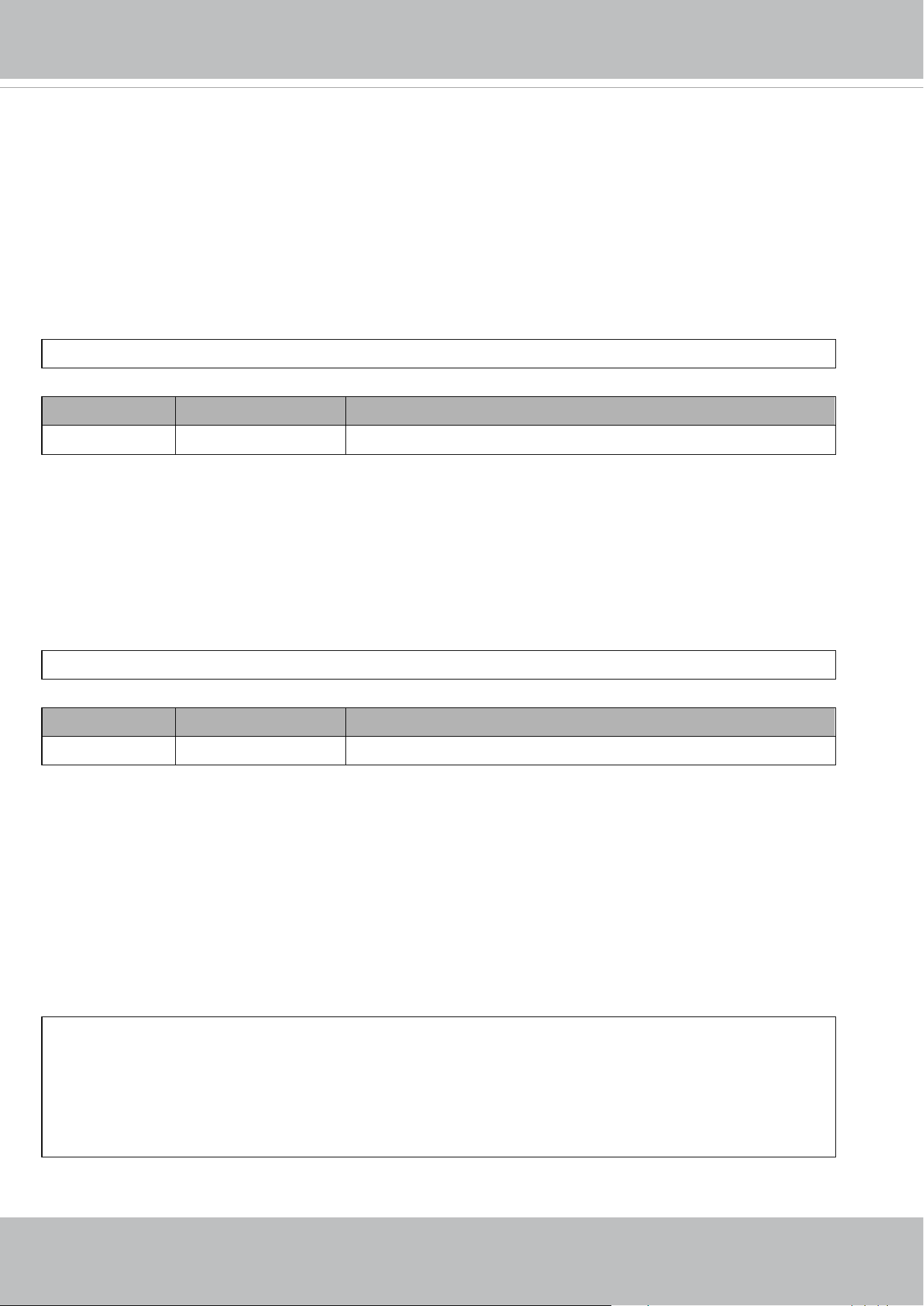
VIVOTEK
User's Manual - 367
8.34 Get wireless signal strength (capability_network_wireless >
0)
Note: This request requires Administrator privileges.
Method: GET/POST
Syntax:
http://<servername>/cgi-bin/admin/getwlsignalstrength.cgi
PARAMETER VALUE DESCRIPTION
N/A N/A Get wireless signal strength.
8.35 WPS transaction (capability_network_wireless > 0)
Note: This request requires Administrator privileges.
Method: GET/POST
Syntax:
http://<servername>/cgi-bin/admin/start_wps.cgi
PARAMETER VALUE DESCRIPTION
N/A N/A Start WPS transaction.
8.36 Peripheral control (capability_peripheral_c<0~(n-1)>_
devicecontrol > 0)
Note: This request requires Administrator privileges.
Method: GET/POST
Syntax: (for control API)
http://<servername>/cgi-bin/admin/peripheral.cgi?channel=<value>&operation=set
[&washer_mode=<value>] – Set washer mode
[&washer_status=<value>] – Set washer status
[&washer_dwelltime=<value>] – Set washer clean time
[&heater_status=<value>] – Set heater status
Example:

VIVOTEK
368 - User's Manual
http://myserver/cgi-bin/admin/peripheral.cgi?channel=0&operation=set&washer_mode=wiper&
washer_status=on
Response:
HTTP/1.0 200 OK\r\n
Cache-control: no-cache\r\n
Pragma: no-cache\r\n
\r\n
"washer_mode : OK\r\n"
"washer_status : FAIL\r\n"
PARAMETER VALUE DESCRIPTION
channel 0~"capability_nvideoin"-1 Channel of the video source.
washer_mode wiper Apply the wiper to the mode of washer control
system.
*Only available when
capability_peripheral_c<0~(n-1)>_washer_supp
ort=1
washer Apply the washer to the mode of washer control
system.
*Only available when
capability_peripheral_c<0~(n-1)>_washer_supp
ort=1
washer_status on Enable the functionality of washer control system.
*Only available when
capability_peripheral_c<0~(n-1)>_washer_supp
ort=1
off Disable the functionality of washer control system.
*Only available when
capability_peripheral_c<0~(n-1)>_washer_supp
ort=1
washer_dwelltime 15~999 Apply washer washer control system operation
time (including the time when spraying and wiper
actions take place).
*Only available when
capability_peripheral_c<0~(n-1)>_washer_supp
ort=1
heater_status auto automatic control the heater component to keep
the device in a workable environment.
*Only available when

VIVOTEK
User's Manual - 369
capability_peripheral_c<0~(n-1)>_heater_suppo
rt=1
trigger heater component is work in force heater once.
*Only available when
capability_peripheral_c<0~(n-1)>_heater_suppo
rt=1
Syntax: (for querying API)
http://<servername>/cgi-bin/admin/peripheral.cgi?channel=<value>&operation=get
[&supportdevice] –Get support peripheral device
[&washer_supportmode] – Get washer support modes
[&washer_mode] – Get washer mode
[&washer_status] – Get washer status
[&washer_dwelltime] – Get washer clean time
[&heater_supportstatus] – Get heater support control status
[&heater_status] – Get heater status
Example:
http://myserver/cgi-bin/admin/peripheral.cgi?channel=0&operation=get&supportdevice&washer_status
Response:
HTTP/1.0 200 OK\r\n
Cache-control: no-cache\r\n
Pragma: no-cache\r\n
\r\n
supportdevice=washer,heater\r\n
washer_status=off\r\n
PARAMETER VALUE DESCRIPTION
channel 0~"capability_nvideoin"-1 Channel of the video source.
supportdevice N/A Get support peripheral device.
washer_supportmode N/A Get the support mode of washer control system,
its value is the same with "capability_peripheral_
c<0~(n-1)>_washer_mode".
*Only available when
capability_peripheral_c<0~(n-1)>_washer_supp
ort=1
washer_mode N/A Get the current mode of washer control system.
It return the value of "washer_mode"
* Available values are listed in

VIVOTEK
370 - User's Manual
"capability_peripheral_c<0~(n-1)>_washer_mod
e"
washer_status N/A Get the current status of washer control module.
The status is 'off' as default, which means the
washer is stopped; and the status 'on' means the
washer is running.
*Only available when
capability_peripheral_c<0~(n-1)>_washer_supp
ort=1
washer_dwelltime N/A Get the current washer clean period of washer
control system.
*Only available when
capability_peripheral_c<0~(n-1)>_washer_supp
ort=1
heater_supportstatus N/A Get the support status of heater control system.
*Only available when
capability_peripheral_c<0~(n-1)>_heater_suppo
rt=1
heater_status N/A Get the current heater status.
Normally it will be 'auto', it means the heater
device is control by internal algorithm to keep in a
suitable environment; Otherwise is 'trigger', it
means the heater device is force enable to heat to
an internal condition.‘trigger’ status will be
transfer to ‘auto’ after reach the internal condition.
*Only available when
capability_peripheral_c<0~(n-1)>_heater_suppo
rt=1
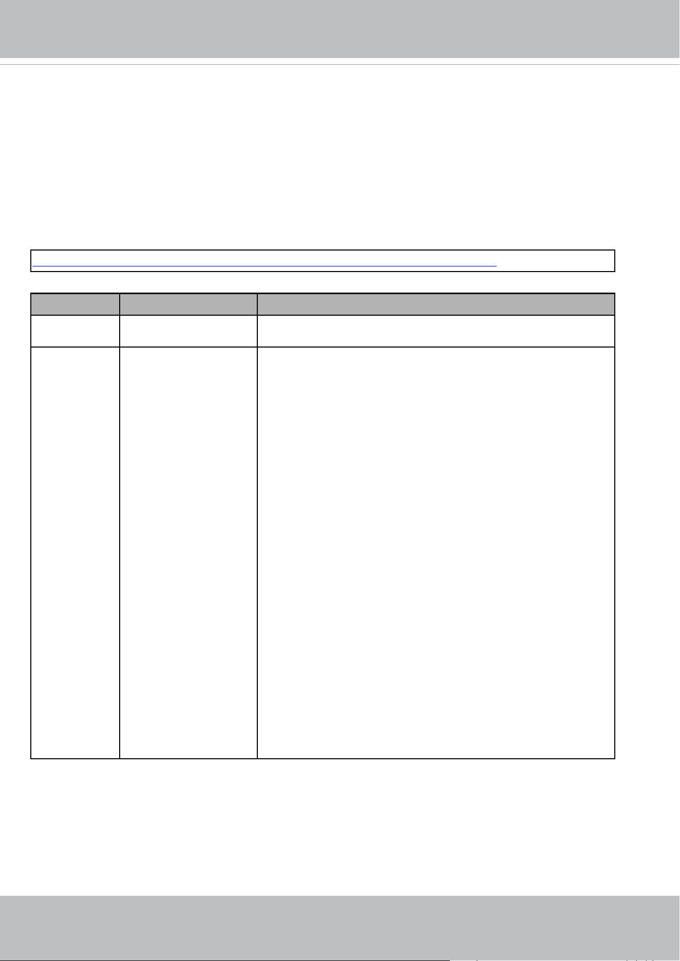
VIVOTEK
User's Manual - 371
8.37 Optimized IR control
(capability_daynight_c<0~(n-1)>_optimizedir > 0)
Note: This request requires Administrator privileges.
Method: GET/POST
Syntax:
http://<servername>/cgi-bin/admin/optimizedir.cgi?function=<value>[&channel=<value
>]
PARAMETER VALUE DESCRIPTION
channel 0~"capability_nvideoin"-1 Channel of the video source.
function getstatus,
onetimeauto
"onetimeauto": Camera will automatically adjust the IR zone one
time only.
"getstatus": Information of optimized IR control status and return
value as below:
optimizedir_c<0~(n-1)>_irmode:
Indicate the IR current mode, available value is “auto” and “manual”
mode.
optimizedir_c<0~(n-1)>_irnum:
The number of IR that camera supports.
optimizedir_c<0~(n-1)>_irstrength:
Only available when irmode is set as manual. It’s a set of integers,
which indicate the strength of each IR LED (e.g. 23,45,100,100).
optimizedir_c<0~(n-1)>_irstatus:
Current IR status, normal / adjusting:
"normal": the IR LED strength has been fixed.
"adjusting": the IR LED strength is adjusting.
Example:

VIVOTEK
372 - User's Manual
http://myserver/cgi-bin/admin/optimizedir.cgi?function=getstatus
Response:
HTTP/1.0 200 OK\r\n
Cache-control: no-cache\r\n
Pragma: no-cache\r\n
\r\n
"optimizedir_c0_irmode='auto'"
"optimizedir_c0_irnum='5'"
"optimizedir_c0_irstrength='1,97,100,100,100'"
"optimizedir_c0_irstatus='normal'"
Syntax: (for control API)
http://<servername>/cgi-bin/admin/optimizedir.cgi
?channel=<value>&operation=<value>&irmode=manual
[&strength=<value>] – Set IR strength
PARAMETER VALUE DESCRIPTION
channel 0~"capability_nvideoin"-1 Channel of the video source.
operation set,
settoall
"set": set the strength of each IR LED separately
"settoall": use fixed strength for all IR LED
irmode auto,
manual
Irmode needs to be set as manual for adjusting IR LED
strength.
strength 1~100 If the operation is set as "set", the number of strength
values need to be the same as it of irnum. However, it
needs only one value for strength when the operation is
set as "settoall".
Example:
http://myserver/cgi-bin/admin/optimizedir.cgi?channel=0&operation=set&irmode=manual&
strength=50,70,50,50,50
Response:
HTTP/1.0 200 OK\r\n
Cache-control: no-cache\r\n
Pragma: no-cache\r\n
\r\n
"optimizedir_c0_irstrength='50,70,50,50,50'"
"optimizedir_c0_irmode='manual'"

VIVOTEK
User's Manual - 373
Example:
http://myserver/cgi-bin/admin/optimizedir.cgi?channel=0&operation=settoall&irmode=manual&strength=100
Response:
HTTP/1.0 200 OK\r\n
Cache-control: no-cache\r\n
Pragma: no-cache\r\n
\r\n
"optimizedir_c0_irstrength='100,100,100,100,100'"
"optimizedir_c0_irmode='manual'"
Example:
http://myserver/cgi-bin/admin/optimizedir.cgi?channel=0&operation=set&irmode=auto&strength=50,70,50,50,
50
Response:
HTTP/1.0 200 OK\r\n
Cache-control: no-cache\r\n
Pragma: no-cache\r\n
\r\n
ERROR: Parameter "irmode" must be set as "manual"!
Example:
http://myserver/cgi-bin/admin/optimizedir.cgi?channel=0&operation=set&strength=50,70,50,50,50
Response:
HTTP/1.0 200 OK\r\n
Cache-control: no-cache\r\n
Pragma: no-cache\r\n
\r\n
ERROR: Must have the "irmode=manual" argument!
Syntax: (for querying API)
http://<servername>/cgi-bin/admin/optimizedir.cgi?channel=<value>&operation=get
[&support_irmode] – list all adjustment mode that IR supports
[&irmode] – Get current IR mode
[&irnum] – Get the number of IR zone

VIVOTEK
374 - User's Manual
PARAMETER VALUE DESCRIPTION
channel 0~"capability_nvideoin"-1 Channel of the video source.
support_irmode N/A List all adjustment mode that IR supports
irmode N/A Get the current IR control mode.
irnum N/A Get the number of IR that camera supports.
Example:
http://myserver/cgi-bin/admin/optimizedir.cgi?channel=0&operation=get&irmode
Response:
HTTP/1.0 200 OK\r\n
Cache-control: no-cache\r\n
Pragma: no-cache\r\n
\r\n
"optimizedir_c0_irmode='auto'"
<End of document>

VIVOTEK
User's Manual - 375
Technical Specications
Technical Specications
Model SD9364-EH-v2
System Information
CPU Multimedia SoC (System-on-Chip)
Flash 128MB
RAM 512MB
Camera Features
Image Sensor 1/2.8" Progressive CMOS
Max. Resolution 1920x1080 (2MP)
Lens Type 30x Optical Zoom, Auto Focus
Focal Length f = 4.3 ~ 129 mm (30x zoom)
Aperture F1.6 ~ F4.7
Iris Type DC-iris
Field of View
2.3° ~ 64° (Horizontal)
1.3° ~ 36° (Vertical)
2.6° ~ 73° (Diagonal)
Shutter Time 1 sec. to 10,000 sec.
WDR Technology WDR Pro
Day/Night Yes
Removable IR-cut Filter Yes
Minimum Illumination
0.195 Lux @ F1.6 (Color)
0.01 Lux @ F1.6 (B/W)
0 Lux with IR illumination on
Pan Speed 0.1° ~ 300° / sec.
Pan Range 360° endless
Tilt Speed 0.1° ~ 300° / sec.
Tilt Range 220° (-110° ~ +110°)
Preset Locations
256 preset locations
128 presets per tour
Pan/Tilt/Zoom
Functionalities
48x digital zoom (4x on IE plug-in, 12x built-
in), Auto pan mode, Auto patrol mode
IR Illuminators
Built-in IR Illuminators up to 250 meters with
Smart IR II, IR LED*2
On-board Storage
Slot type: MicroSD/SDHC/SDXC card slot
Seamless Recording
Video
Compression H265, H264, MJPEG
Maximum Frame Rate
H.265 & H.264: 60 fps @ 1920x1080
MJPEG: 30 fps @ 1920x1080
Maximum Streams 4 simultaneous streams
S/N Ratio 66 dB
Dynamic Range 130 dB
Video Streaming
Adjustable resolution, quality and constant
bit rate control, Smart Stream II
Image Settings
Time stamp, text overlay, ip and mirror,
congurable brightness/contrast/
saturation/sharpness, white balance,
exposure control, gain, backlight
compensation, privacy masks (Up to 24),
scheduled prole settings, defog, 3DNR, EIS,
HLC
Audio
Audio Capability Two-way Audio (full duplex)
Compression G.711, G.726
Interface
External microphone input
External line output
Network
Users Live viewing for up to 10 clients
Protocols
802.1X, ARP, CIFS/SMB, CoS, DDNS, DHCP,
DNS, FTP, HTTP, HTTPS, ICMP, IGMP, IPv4, IPv6,
NTCIP, NTP, PPPoE, QoS, RTSP/RTP/RTCP,
SMTP, SNMP, SSL, TCP/IP, TLS, UDP, UPnP
Interface
10 Base-T/100 Base-TX Ethernet (RJ-45)
*It is highly recommended to use standard
CAT5e & CAT6 cables which are compliant
with the 3P/ETL standard.
ONVIF
Supported, specication available at
www.onvif.org
Intelligent Video
Video Motion Detection Five-window video motion detection
Auto-Tracking Auto-tracking on moving object
VADP Package
Genetec package, Amazon Kinesis Video
Streams
Alarm and Event
Alarm Triggers
Motion detection, manual trigger, digital
input, periodical trigger, system boot,
recording notication, audio detection, SD
card life expectancy
Alarm Events
Event notication via digital output, email,
HTTP, FTP, NAS server, SD card
File upload via email, HTTP, FTP, NAS server,
SD card
General
Connectors
RJ-45 cable connector for Network
10/100Mbps PoE connection*1
Audio input*1
Audio output*1
AC/DC 24V power input*1
Digital input*4
Digital output*2
RS-485 for PTZ control (PelcoD protocol,
Baud rate 2400)*1
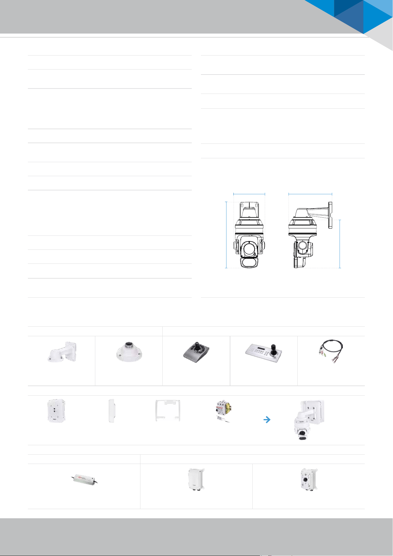
VIVOTEK
User's Manual - 376
Technical Specications
System Information
Video
Time stamp, text overlay, ip and mirror,
congurable brightness/contrast/
scheduled prole settings, defog, 3DNR, EIS,
Audio
Network
Supported, specication available at
Intelligent Video
recording notication, audio detection, SD
Event notication via digital output, email,
Technical Specications
LED Indicator System power and status indicator
Power Input
PoH/PoE (95W)
AC/DC 24V
Power Consumption
PoH/PoE (95W):
Max. 70 W (Heater on, IR on)
Max. 51 W (Heater off, IR on)
AC/DC 24V:
Max. 63 W (Heater on, IR on)
Max. 45 W (Heater off, IR on)
Dimensions 237 x 364 mm
Weight
7.1 kg (with bracket)
5.7 kg (without bracket)
Casing IP66, IK10, NEMA 4X
Safety Certications CE, FCC Class A, VCCI, C-Tick, UL
Operating Temperature
Starting Temperature:
-40°C ~ 55°C (-40°F ~ 131°F)
Working Temperature:
-40°C ~ 55°C (-40°F ~ 131°F),
DC 24V power input
-50°C ~ 55°C (-58°F ~ 131°F),
AC 24V/PoH (95W) power input
Humidity 98%
Warranty 36 months
System Requirements
Operating System
Microsoft Windows 8/7
Mac 10.12 (Chrome only)
Web Browser
Chrome 58.0 or above
Internet Explorer 10/11
Other Players
VLC: 1.1.11 or above
QuickTime: 7 or above
Included Accessories
Others
Wall mount bracket, I/O cable, screws,
waterproof connectors, terminal blocks,
quick installation guide, warranty card,
alignment sticker, ground wire, T25 star
driver, desiccant bags
Dimensions
499 mm
237 mm 326 mm
364 mm
Compatible Accessories
PoE Kit/Power Adapter
24VDC 24VAC
HLG-120 H-24 AA-351 AA-352
Industrial 24VDC/120W Power Supply, IP67 Outdoor Power Box, 24VAC/144W, IP67, IK10 Outdoor Power Box, 24VAC/144W, IP67, IK10
Cabinet
AT-CAS-001 AT-CAB-002 AT-SUN-002 AT-SWH-000
Cabinet for Speed
Dome
Cabinet for HLG Power
Supply
Sunshield Power Safety Kit
Mounting Kits Others
AM-220 AM-529 AJ-001 AJ-002 AO-007
Wall Mount Bracket
(standard package)
Mounting Adapter USB Joystick USB Joystick I/O Combo Cable
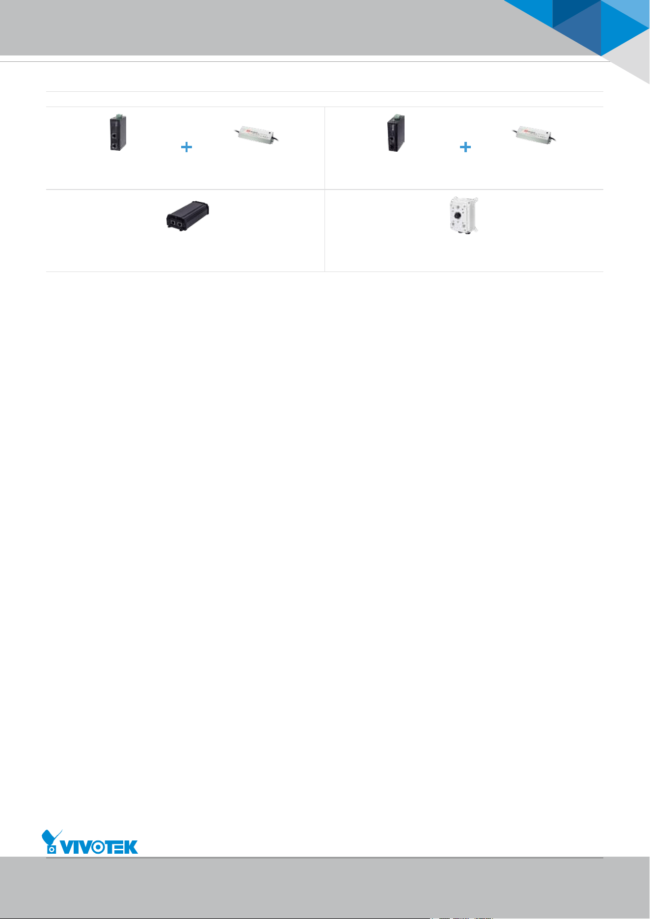
VIVOTEK
User's Manual - 377
Technical Specications
Safety Certications
Included Accessories
Dimensions
Compatible Accessories
PoE Kit/Power Adapter
Cabinet
Mounting Kits
Compatible Accessories
95W PoH/PoE
AW-IHH- 0100 HLG-120H-54 AW-IHH-0200 HLG-120H-54
Industrial 1xGE 95W PoH/PoE
Injector
Industrial 54VDC/120W Power
Supply, IP67
Industrial 1xGE 95W PoH/PoE + 1x
SFP GE Switch
Industrial 54VDC/120W Power
Supply, IP67
AP-GIC-011A-095 AP-GIC-015B-095
1xGE 95W PoH/PoE Injector with Surge Protection 12KV Outdoor 1xGE 95W PoH/PoE Injector with Surge Protection 12KV, IP67,
IK10
All specications are subject to change without notice. Copyright © VIVOTEK INC. All rights reserved. Ver. 2
6F, No.192, Lien-Cheng Rd., Chung-Ho, New Taipei City, 235, Taiwan, R.O.C. | T: +886-2-82455282 | F: +886-2-82455532 | E: sales@vivotek.com | W: www.vivotek.com

VIVOTEK
378 - User's Manual
Technology License Notice
Notices from HEVC Advance:
THIS PRODUCT IS SOLD WITH A LIMITED LICENSE AND IS AUTHORIZED TO BE USED ONLY
IN CONNECTION WITH HEVC CONTENT THAT MEETS EACH OF THE THREE FOLLOWING
QUALIFICATIONS: (1) HEVC CONTENT ONLY FOR PERSONAL USE; (2) HEVC CONTENT THAT
IS NOT OFFERED FOR SALE; AND (3) HEVC CONTENT THAT IS CREATED BY THE OWNER OF
THE PRODUCT. THIS PRODUCT MAY NOT BE USED IN CONNECTION WITH HEVC ENCODED
CONTENT CREATED BY A THIRD PARTY, WHICH THE USER HAS ORDERED OR PURCHASED
FROM A THIRD PARTY, UNLESS THE USER IS SEPARATELY GRANTED RIGHTS TO USE THE
PRODUCT WITH SUCH CONTENT BY A LICENSED SELLER OF THE CONTENT. YOUR USE OF
THIS PRODUCT IN CONNECTION WITH HEVC ENCODED CONTENT IS DEEMED ACCEPTANCE OF
THE LIMITED AUTHORITY TO USE AS NOTED ABOVE.
H.264
THIS PRODUCT IS LICENSED UNDER THE AVC PATENT PORTFOLIO LICENSE FOR THE
PERSONAL AND NON-COMMERCIAL USE OF A CONSUMER TO (i) ENCODE VIDEO IN
COMPLIANCE WITH THE AVC STANDARD ("AVC VIDEO") AND/OR (ii) DECODE AVC VIDEO
THAT WAS ENCODED BY A CONSUMER ENGAGED IN A PERSONAL AND NON-COMMERCIAL
ACTIVITY AND/OR WAS OBTAINED FROM A VIDEO PROVIDER LICENSED TO PROVIDE AVC
VIDEO. NO LICENSE IS GRANTED OR SHALL BE IMPLIED FOR ANY OTHER USE. ADDITIONAL
INFORMATION MAY BE OBTAINED FROM MPEG LA, L.L.C. SEE HTTP://WWW.MPEGLA.COM
AMR-NB Standard
THIS PRODUCT IS LICENSED UNDER THE AMR-NB STANDARD PATENT LICENSE AGREEMENT. WITH
RESPECT TO THE USE OF THIS PRODUCT, THE FOLLOWING LICENSORS’ PATENTS MAY APPLY:
TELEFONAKIEBOLAGET ERICSSON AB: US PAT. 6192335; 6275798; 6029125; 6424938; 6058359. NOKIA
CORPORATION: US PAT. 5946651; 6199035. VOICEAGE CORPORATION: AT PAT. 0516621; BE PAT. 0516621;
CA PAT. 2010830; CH PAT. 0516621; DE PAT. 0516621; DK PAT. 0516621; ES PAT. 0516621; FR PAT. 0516621;
GB PAT. 0516621; GR PAT. 0516621; IT PAT. 0516621; LI PAT. 0516621; LU PAT. 0516621; NL PAT. 0516621;
SE PAT 0516621; US PAT 5444816; AT PAT. 819303/AT E 198805T1; AU PAT. 697256; BE PAT. 819303; BR PAT.
9604838-7; CA PAT. 2216315; CH PAT. 819303; CN PAT. ZL96193827.7; DE PAT. 819303/DE69611607T2; DK
PAT. 819303; ES PAT. 819303; EP PAT. 819303; FR PAT. 819303; GB PAT. 819303; IT PAT. 819303; JP PAT. APP.
8-529817; NL PAT. 819303; SE PAT. 819303; US PAT. 5664053. THE LIST MAY BE UPDATED FROM TIME TO
TIME BY LICENSORS AND A CURRENT VERSION OF WHICH IS AVAILABLE ON LICENSOR’S WEBSITE AT
HTTP://WWW.VOICEAGE.COM.

VIVOTEK
User's Manual - 379
Electromagnetic Compatibility (EMC)
FCC Statement
This device compiles with FCC Rules Part 15. Operation is subject to the following two conditions.
■ This device may not cause harmful interference, and
■ This device must accept any interference received, including interference that may cause undesired
operation.
This equipment has been tested and found to comply with the limits for a Class A digital device, pursuant
to Part 15 of the FCC Rules. These limits are designed to provide reasonable protection against
harmful interference when the equipment is operated in a commercial environment. This equipment
generates, uses, and can radiate radio frequency energy and, if not installed and used in accordance
with the installation manual, may cause harmful interference to radio communications. Operation of this
equipment in a residential area is likely to cause harmful interference, in which case the user will be
required to correct the interference at his own expense.
CE Mark Warning
This is a Class A product. In a domestic environment, this product may cause radio interference, in which
case the user may be required to take adequate measures.
VCCI Warning
この装置は、情報処理装置等電波障害自主規制協議会(VCCI)の基準にづくクラスB情報技術装置です。この
装置は、家庭環境で使用することを目的としていますが、この装置がラジオやテレビジョン受信機に近接して使
用されると、受信障害を引き起こすことがあります。
取扱説明書に従って正しい取り扱いをして下さい
Liability
VIVOTEK Inc. cannot be held responsible for any technical or typographical errors and reserves the right
to make changes to the product and manuals without prior notice. VIVOTEK Inc. makes no warranty
of any kind with regard to the material contained within this document, including, but not limited to, the
implied warranties of merchantability and fitness for any particular purpose.