
Safe Operation Practices • Introduction • Set-Up • Controls & Operation • Product Care • Specications
WARNING
READ AND FOLLOW ALL SAFETY RULES AND INSTRUCTIONS IN THIS MANUAL
BEFORE ATTEMPTING TO OPERATE THIS VEHICLE.
FAILURE TO COMPLY WITH THESE INSTRUCTIONS MAY RESULT IN PERSONAL INJURY.
OperatOr’s Manual
Form No. 769-26020
(January 29, 2021)
NOTE: This Operator’s Manual covers several models. Features may vary by model. Not all features in this manual are applicable to all
models and the model depicted may differ from yours.
Utility Vehicle
MX 550/750
Safe Operation Practices ........................................ 2
Introduction ............................................................. 5
Set-Up ....................................................................... 6
Controls & Operation .............................................. 7
Product Care ...........................................................12
Specications .......................................................... 21
Warranty ................................................................ 23
Table of Contents
Safe Operation Practices 1
2
Operation
General Operation
1. Read, understand, and follow all
instructions on the vehicle and in
the manual before attempting to
operate or service vehicle. Keep this
manual in a safe place for future and
regular reference and for ordering
replacement parts.
2. This is an off-highway utility vehicle
and it should not be operated on public
highways. Know and comply with all
laws and regulations governing the use
of off-highway vehicles in your area.
3. This vehicle handles and maneuvers
differently than a normal passenger
car. Sharp high speed turns and abrupt
maneuvers can cause vehicle to roll over
or go out of control. Slow down when
turning and avoid abrupt maneuvers.
4. Handling and maneuvering
characteristics of vehicle change
depending upon cargo load. Heavy
loads affect steering, braking, stability,
and overall handling of vehicle.
5. Be familiar with all instructions and
controls and their proper operation
before starting vehicle.
6. Never allow adults to operate this
vehicle without proper instruction.
7. Never allow children under 16 years
old to operate this vehicle. Children
16 years old and over should read
and understand the operation
instructions and safety rules in this
manual and should be trained and
supervised by a parent unless driver has
obtained a state-issued motor vehicle
driver’s licence.
8. Watch for traffic when operating near
or crossing roadways. This vehicle is not
intended for use on any public roadway.
9. Do not operate this vehicle while under
the influence of alcohol or drugs.
10. Never carry more than one passenger.
This vehicle is designed to carry the
driver and one passenger only. No riders
are allowed in cargo box or anywhere
else on vehicle, except in the driver and
passenger seats.
11. Keep all body parts (i.e. head, arms,
hands, legs, feet) inside vehicle when
vehicle is in motion.
12. Always remain seated and keep both
hands on the steering wheel when
driving the vehicle.
13. Sit on the center of the seat and keep
both feet within the foot platform
perimeter. Clean foot platform if dirty
and remove any debris from around foot
controls, e.g. brake pedal.
14. Do not misuse the vehicle. Reckless
operation can lead to accidents, severe
bodily injury or death.
15. Inspect area around vehicle before
moving, especially in reverse. Back up
slowly. Always look down and behind
before and while backing to avoid a
back-over accident. Keep bystanders out
of area.
16. Avoid driving through water, since loss
of control may occur. Drive belt may
slip if exposed to water thus reducing
vehicle pulling power and stopping
vehicle entirely. Water depth should not
exceed 15” (38 cm).
17. Always use vehicle lights while
operating in low light situations.
18. Do not mount or leave vehicle while it is
in motion or in actual operation.
19. Avoid sudden starts, stops, or turns and
always use a level turn-around area.
20. Never leave vehicle unattended with the
engine running. Move the shift lever to
“PARK” position, turn ignition key to the
“OFF” position and remove the key.
21. Check overhead clearances carefully
before driving under low hanging tree
branches, wires, power lines, bridges,
before entering or leaving buildings,
or in any other situation where the
operator and/or occupant protection
structure (OPS) may be struck, which
could result in serious injury.
22. Always use the occupant protection
structure (OPS) and seat belt for safe
operation. Overturning the utility
vehicle without an OPS, or with an OPS
and the seat belt unfastened, can result
in death or injury.
23. Always use the seat belt and never
remove the occupant protection
structure (OPS) or operate the vehicle
without the OPS.
24. The doors are designed to assist in
keeping the operator and passenger
inside the vehicle during operation.
Do NOT operate vehicle without doors
in place.
25. Improper use of the vehicle or failure
to properly maintain it could result
in decreased vehicle performance or
personal injury.
26. Engine must be stopped when cleaning,
servicing, adjusting, repairing, or
installing attachments on utility vehicle.
27. After striking foreign objects, stop the
vehicle and shut off the engine. Inspect
for damage and repair the damage
before restarting and operating.
28. Do not start or operate vehicle in an
inside area, unless it is adequately
ventilated. Engine exhaust contains
carbon monoxide fumes, which are very
poisonous and can be deadly.
29. Assure safety interlock switch is adjusted
correctly so engine cannot be started
unless gearshift is in the “PARK” position
with the brake pedal depressed.
30. Do not touch engine or exhaust
components while engine is running or
soon after it is stopped. They will be hot
and can cause a burn.
31. Always inspect your vehicle each time
you use it to make sure it is in safe
operating condition. Always follow the
inspection and maintenance procedures
and schedules described in this manual.
32. Do not use the differential lock when
driving down hill. Do not use the
differential lock at speeds over 25
mph. Allow for greater turning radius
and more difficult steering when the
differential lock is engaged.
33. If situations occur which are not covered
in this manual, use care and good
judgement. Contact your local service
center or call toll free 1-877-282-8684 for
the name of your nearest service center.
Occupant Size and Capacity
1. Make sure operators are at least 16 years
old and have a valid driver’s license.
2. Each occupant should be able to sit with
their back against the seat, feet flat on
the floor, and hands on the steering
wheel or handholds.
FAILURE TO FOLLOW THE WARNINGS CONTAINED IN THIS MANUAL CAN RESULT IN SERIOUS INJURY OR DEATH.
Particularly important information is distinguished in this manual by the following notations:
This symbol points out important safety instructions which, if not followed, could endanger the personal safety and/or property of yourself and others.
Read and follow all instructions in this manual before attempting to operate this vehicle. Failure to comply with these instructions may result in personal
injury. When you see this symbol. HEED ITS WARNING!
DANGER: Indicates death or serious injury will result if proper precautions are not taken.
WARNING: Indicates death, serious injury, or property damage can result if proper precautions are not taken.
CAUTION: Indicates some injury or property damage may result if proper precautions are not taken.
Note: Provides key information to make procedures easier or clearer.
WARNING
California Proposition 65
Engine Exhaust, some of its constituents, and certain vehicle components contain or emit chemicals known to the State of California to cause cancer and birth defects or other reproductive harm.
Battery posts, terminals, and related accessories contain lead and lead compounds, chemicals known to the State of California to cause cancer and reproductive harm. Wash hands after handling.
DANGER
This vehicle was built to be operated according to the safe operation practices in this manual. As with any type of off-highway utility vehicle, carelessness or error on the part of the operator
can result in serious injury. Failure to observe the following safety instructions could result in serious injury or death.

3Section 1 — Safe operation practiceS
3. The operator should be tall enough to
wear the seat belt properly and reach
all controls.
4. Passengers should also be tall enough
for the seat belt to fit properly and be
able to brace themselves, as necessary,
by placing both feet firmly on the
floor while gripping the handholds.
Keep all body parts completely inside
the vehicle.
Dress Properly
1. Proper clothing can reduce the severity
of injury in the event of an accident.
2. Always wear appropriate eye protection
and protective clothing. It is also
recommended that you wear a properly
fitting D.O.T. approved helmet.
Slope Operation
Slopes are a major factor related to loss of
control and rollover accidents, which can result
in severe injury or death. If a slope is steeper
than a 15° incline, do not operate this vehicle
on that area. Exercise extreme caution while
operating on slopes.
Do:
1. Travel straight up and down slopes, not
across. Exercise extreme caution when
changing direction on slopes.
2. Travel slowly while on a slope. Always
keep the forward speed limited when
going down slopes to take advantage of
the engine braking action.
3. Keep all movement on the slopes slow
and gradual. Avoid starting or stopping
on a slope.
4. Avoid slopes with slippery, loose, or bumpy
surfaces as they are especially hazardous.
5. Use extra care while carrying cargo. It
may affect the stability of the vehicle.
Spread the load evenly and tie down.
Do Not:
1. Do not travel near drop-offs, ditches,
or embankments. The vehicle could
suddenly turn over if a wheel is over
the edge of a cliff, ditch, or if an edge
caves in.
2. Do not stop or start suddenly when
going uphill or downhill. Be especially
cautious when changing direction on
slopes.
3. Do not turn sideways to the hill. The
vehicle may roll over. If you must turn, go
slow and do so carefully and gradually.
4. Do not carry cargo or tow loads on
steep slopes.
Towing
1. Always use an approved hitch and hitch
point provided on the utility vehicle.
2. Do not tow more than 1200 lbs (544 kg)
rolling weight (i.e. trailer plus cargo).
3. Never load more than 110 lbs (50 kg)
tongue weight on tow bracket provided.
4. Go slow and use extra care when towing
a trailer. Allow for increased braking
distance. Load trailer properly.
5. Do not tow heavy loads on slopes
greater than 5° incline. When going
downhill or turning, the extra weight
tends to push the tow vehicle and may
cause you to lose control (i.e. braking
and steering ability are reduced, towed
equipment may jack-knife and cause
utility vehicle to overturn).
Cargo Box Loading/Operation
1. Do not exceed vehicle’s Total Load
Capacity rating of 1000 lbs (453.5 kg)
This includes operator, passenger,
accessories, and cargo.
2. Do not exceed 500 lbs. (226.7 kg) load in
cargo box.
3. Spread load evenly and secure to
prevent movement.
4. Do not load above height of cargo box
front panel. Load could shift forward and
injure driver or passenger.
5. Avoid loads which exceed the physical
dimensions of cargo box.
6. Go slow. Heavy loads will affect steering,
braking, stability, and overall handling of
the vehicle. Limit loads to those that can
be safely controlled.
7. Avoid sudden starts, stops, and turns
which could cause load to shift.
Cargo Box Lift
1. Stop vehicle on level ground, move
the shift lever into the “PARK” position
before raising cargo box.
2. On manual lift units, unload cargo box
before raising cargo box.
3. Do not operate vehicle with cargo box in
raised position.
4. Do not operate vehicle with cargo box
latch unlatched. Always re-latch upon
manually lowering cargo box.
When using optional electric lift:
a. Stay in driver’s seat.
b. Keep body parts away from
cargo box and keep all
bystanders away.
c. Do not allow rear wheels to hang
over the edge of a drop-off when
raising cargo box. The load in the
cargo box may shift causing the
vehicle to tip over backwards.
Safety Frame (OPS)
1. Your vehicle is equipped with an
occupant protection structure (OPS)
which must be maintained in a fully
functional condition. Use care when
driving through doorways or spaces
with a low overhead.
a. Never modify the OPS in any way.
b. Never attempt to straighten
or reweld any part of the main
frame or retaining brackets that
have been damaged. Doing so
may weaken the structure and
endanger your safety.
c. Never secure any parts other
than manufacturer approved
accessories on the main frame
or attach the safety frame with
anything other than the special
fasteners specified.
d. Never attach ropes, chains,
or cables to the OPS for
pulling purposes.
e. Although the OPS, when used
with a properly secured seat
belt, provides a crush-protective
environment in the event of a
tip-over or rollover, never take
unnecessary risks.
Children
1. Tragic accidents can occur if the
operator is not alert to the presence of
children. Children are often attracted to
the vehicle. They do not understand the
dangers. Never assume that children will
remain where you last saw them. Avoid
run over accidents.
a. Keep children out of the
immediate area of the vehicle
and in watchful care of a
responsible adult other than
the operator.
b. Be alert and turn the vehicle off if
a child enters the area.
c. Before and while backing,
look behind and down for
small children.
d. Never carry small children, they
may fall off and be seriously
injured or interfere with safe
vehicle operation.
e. Use extreme care while
approaching blind corners,
doorways, shrubs, trees, or other
objects that may block your
vision of a child who may run into
the path of the vehicle.
f. Remove key when vehicle
is unattended to prevent
unauthorized operation.
2. Never allow children under 16 years
old to operate this vehicle. Children
16 years old and over should read and
understand the operation instructions
and safety rules in this manual, should
be trained and supervised by a parent
and have obtained a state-issued motor
vehicle driver’s license.
3. Do not let children ride in the cargo
box, in the driver’s or passenger’s lap
or anywhere other than the passenger
seat. Never give small children a ride; not
even in the passenger seat. They may
fall off.
Service
Safe Handling of Fuel:
1. To avoid personal injury or property
damage use extreme care in handling
fuel. Fuel is extremely flammable
and the vapors are explosive. Serious
personal injury can occur when fuel is
spilled on yourself or your clothes which
can ignite. Wash your skin and change
clothes immediately.
a. Use only an approved
fuel container.
b. Never carry or fill containers
inside the vehicle’s bed or on
a truck or trailer. Always place
containers on the ground away
from your vehicle before filling.
c. When practical, remove gas-
powered vehicle from the truck
or trailer and refuel it on the
ground. If this is not possible,
then refuel on a trailer with a
portable container, rather than
from a fuel dispenser nozzle.
d. Keep the nozzle in contact
with the rim of the fuel tank or
container opening at all times
until fueling is complete. Do not
use a nozzle lock-open device.
e. Extinguish all cigarettes, cigars,
pipes, and other sources
of ignition.
4 Section 1 — Safe operation practiceS
f. Never fuel indoors.
g. Never remove gas cap or
add fuel while the engine is
hot or running. Allow engine
to cool at least five minutes
before refueling.
h. Never over fill fuel tank. Fill
tank to no more than one
inch below bottom of filler
neck to allow space for fuel
expansion. Leave additional
room for fuel expansion if the
utility vehicle will be in a high-
altitude situation.
i. Replace fuel cap and
tighten securely.
j. If fuel is spilled, wipe it off
immediately. Move vehicle to
another area. Wait 5 minutes
before starting the engine.
k. To reduce fire hazards, keep
engine compartment and
exhaust system free of grass,
leaves, or other debris build-up.
Clean up oil or fuel spillage and
remove any fuel soaked debris.
l. Never store the vehicle or fuel
container inside where there
is an open flame, spark or pilot
light as on a water heater, space
heater, furnace, clothes dryer, or
other gas appliances.
General Service
1. Never run an engine indoors or in a
poorly ventilated area. Engine exhaust
contains carbon monoxide, an odorless,
and deadly gas.
2. Before cleaning, repairing, or inspecting,
make certain all moving parts have
stopped. Remove the key to prevent
unintended starting.
3. Check brake operation frequently
as it is subjected to wear during
normal operation. Adjust and service
as required.
4. The cooling system is under pressure,
never remove the radiator cap when
the system is hot. Slowly turn the cap to
the first stop to release pressure before
removing the cap.
5. Keep all nuts, bolts, and screws tight to
be sure the vehicle is in safe working
condition.
6. Never tamper with the safety interlock
system or other safety devices. Check
their proper operation regularly.
7. Never attempt to make adjustments or
repairs to the vehicle while the engine
is running.
8. Wait for vehicle to cool before servicing
exhaust or coolant system.
9. Stop vehicle on level ground. Place shift
lever in park before servicing.
10. Maintain or replace safety and
instruction labels, as necessary.
11. Follow the vehicle maintenance and
service schedules to ensure that
all mechanical and safety systems
are working properly and not worn
excessively. Failure to do so can result in
accidents, injuries, or death.
12. Observe proper disposal laws and
regulations for gas, oil, etc. to protect
the environment.
13. Prior to disposal, determine the proper
method to dispose of waste from your
local Environmental Protection Agency.
Recycling centers are established to
properly dispose of materials in an
environmentally safe fashion.
14. Use proper containers when draining
fluids. Do not use food or beverage
containers that may mislead someone
into drinking from them. Properly
dispose of the containers immediately
following the draining of fluids.
15. Do NOT pour oil or other fluids into the
ground, down a drain or into a stream,
pond, lake, or other body of water.
Observe Environmental Protection
Agency regulations when disposing
of oil, fuel, coolant, brake fluid, filters,
batteries, tires, and other harmful waste.
16. We do not recommend the use of a
pressure washer to clean your vehicle.
They may cause damage to electrical
components; wheel spindles; pulleys;
bearings; or the engine. The use of high-
pressure water will result in shortened
life and reduce serviceability.
Do not modify engine
To avoid serious injury or death, do not modify
engine in any way. Tampering with engine
can lead it to operate at unsafe speeds. Never
tamper with factory setting of the engine and
its components.
Notice Regarding Emissions
Where applicable, this vehicle is certified to
federal EPA and California Air Resources Board
(CARB) emissions standards for Off-Highway
Recreational Vehicles (OHRV). The Engine
Owner’s Manual is supplied by the engine
manufacturer, and provides additional
information relating to the emission system,
warranty, and maintenance of the engine in
accordance with EPA and/or CARB regulations.
Consult your engine manual for the fuel
requirements for your engine.
Gasoline powered products may be equipped
with the following emission control systems:
Engine Modification (EM), Oxidizing Catalyst
(OC), Oxygen Sensor (O2S), Multi-port Fuel
Injection (MFI), Electronic Control Module
(ECM), Secondary Air Injection (SAI) and Three
Way Catalyst (TWC). When required, models
are equipped with low permeation fuel lines
and fuel tanks for evaporative emission
control. Please contact Customer Support
for information regarding the evaporative
emission control configuration for your model.
Spark Arrestor
WARNING
This vehicle is equipped with an internal combustion
engine and should not be used on or near any
unimproved forest-covered, brush-covered, or grass-
covered land unless the engine’s exhaust system is
equipped with a spark arrestor meeting applicable
local or state laws (if any).
The spark arrestor should be maintained in
effective working order by the operator. In the
State of California the above is required by law
(Section 4442 of the California Public Resources
Code). Other states may have similar laws.
Federal laws apply on federal lands.
A replacement spark arrestor for the muffler
is available through your nearest engine
authorized service dealer or contact the service
department, P.O. Box 361131, Cleveland, Ohio
44136-0019.
Safety Labels
Safety labels that may appear on the product
are reproduced on this page. Read, understand,
and follow all instructions on the machine
before attempting to assemble and/or operate.
Battery
Remove rubber cap Connect exhaust tube
Exhaust opening
Instruction:
Preparing the battery for
lling with electrolyte (acid)
Take o the rubber sealing cap
and remove lling plugs.
Replace rubber cap with
exhaust tube provided.
Filling electrolyte (acid):
Fill battery with electrolyte (diluted sulphuric acid) with a specic
Gravity of: cool or temperate climate 1.270-1.280
Tropical climate 1.250-1.260
The electrolyte temperature when lling must not be lower than 15°c or
higher than 30°c.
Fill battery to upper level as indicated on the battery case.
Leave battery to stand for at least 30 minutes after lling.
Electrolyte level may fall during this period, rell to upper level
before charging.
WARNING
The battery contains or emits chemicals known in certain quantities to
cause cancer, birth defects or other reproductive harm.
5
Introduction
2
Important Notice
This UTV is designed and manufactured for OFF-ROAD use only. It is illegal and unsafe to operate this UTV on any public street, road or highway.
This UTV complies with all applicable OFF-ROAD noise level and spark arrestor laws and regulations in effect at the time of manufacture.
Please check your local riding laws and regulations before operating this UTV.
When the temperature is below -4° F (-20° C), park the UTV in a place where the temperature is higher than -4° F (-20° C). Start the UTV after the UTV has warmed up. Please see the manual on the warming up process.
Follow the proper parking procedures when the temperature is higher than 100° F (38° C): turn off the engine; make sure the radiator fan is on for 3 minutes before turning off the power switch.
Starting the UTV for the first time will take longer because the fuel will need to reach the fuel injectors. To start the UTV the first time, hold the ignition key on at 5-second intervals. Allow the starter to rest 15 seconds
between each start attempt.
Universal Symbols
As a guide to the operation of your vehicle, various universal symbols have been utilized on the instruments and controls. The symbols are shown below with an indication of their meaning.
Warning/Danger/Caution Symbol
Diesel Fuel
Engine Coolant -- Temperature
P
Parking Brake
Battery Charging Condition
Engine Oil -- Pressure
Turn Signal/Hazard
Differential Lock
Position Light Bulb
Lift Cylinder -- Retract
Lift Cylinder -- Extend
Lift Cylinder -- Float
Hazard Warning Lights
Master Lighting Switch
Audible Warning Device
Fault Indicator Light of EPS System
2WD/4WD
Record Product Information
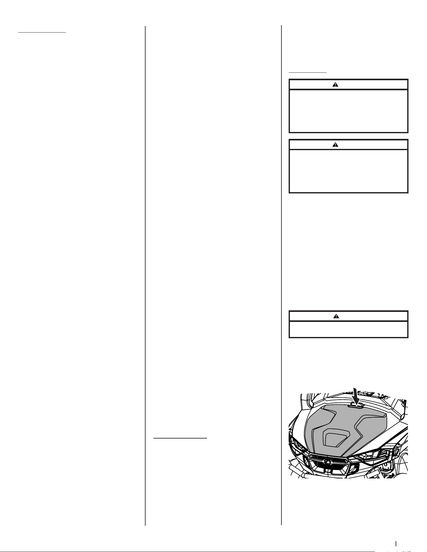
Before setting up and operating your new utility vehicle please locate the model
plate and record the information in the provided area to the right. You can locate the
model plate by looking on the frame above the left rear tire. See the image below.
This information will be necessary, should you seek technical support via our web
site, Customer Support Department, or with a local authorized service dealer.
Model NuMber
Serial NuMber
6
Set-Up
3
Note: This Operator’s Manual covers several models. Utility vehicle features may vary by model. Not all features in this manual are applicable to all utility vehicle
models and the utility vehicle depicted may differ from yours.
Note: All references in this manual to the left or right side and front or back of the utility vehicle are from the operating position only. Exceptions, if any, will be specified.
Note: Some components may come already assembled. If they are already assembled, skip ahead to the next step.
Thank you for purchasing this product. It was carefully engineered to provide
excellent performance when properly operated and maintained.
Please read this entire manual prior to operating. It instructs you how to
safely and easily set up, operate and maintain your vehicle. Please be sure
that you, and any other persons who will operate the vehicle, carefully follow
the recommended safety practices at all times. Failure to do so could result in
personal injury or property damage.
All information in this manual is relative to the most recent product information
available at the time. Review this manual frequently to familiarize yourself
with the vehicle, its features and operation. Please be aware that this
Operator’s Manual may cover a range of product specifications for various
models. Characteristics and features discussed and/or illustrated in this
manual may not be applicable to all models. We reserve the right to change
product specifications, designs and vehicle without notice and without
incurring obligation.
If applicable, the power testing information used to establish the power rating of
the engine equipped on this vehicle can be found at www.opei.org or the engine
manufacturer’s web site.
If you have any problems or questions concerning the vehicle, phone your
local authorized service dealer or contact us directly. We want to ensure your
complete satisfaction at all times.
Throughout this manual, all references to right and left side of the vehicle are
observed from the operating position.
Thank You
CAUTION
To avoid personal injury: Be sure to check and service the vehicle on a level surface with the engine shut off, the parking brake “ON” and any attachments lowered to the ground.
Pre-Start Check Items
To better prevent or avoid unnecessary repairs, it is important to know the condition of the vehicle well. Check it before operating.
Contents of Crate
• Utility Vehicle (1) • Operator’s Manual (1) • Tool Kit
• Product Registration Card (1)
P Visually inspect the vehicle
P Check engine oil level
P Check air filter
P Check brake fluid level
P Check coolant level
P Clean radiator screen (when used in dusty or muddy conditions)
P Check brake and pedal
P Check parking brake
P Check indicators, gauges and meters
P Check lights
P Check seat belts and roll-over protective structures
P Check front and rear joint boots
P Check tire inflation pressure
P Check fuel
P Check danger, warning and caution labels
7
Controls & Operation
4
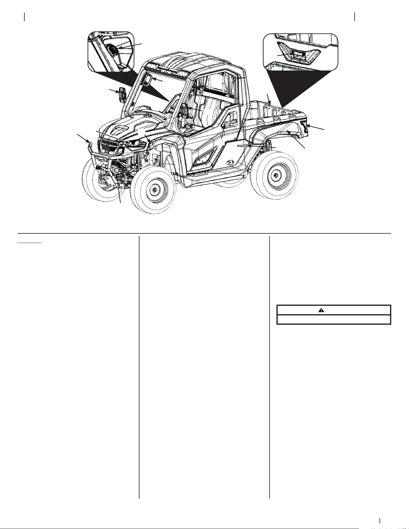
(A)
(B)
(E)
(F)
(H, I & D)
(C)
(D)
(G)
(J)
(K)
(L)
(M)
(M)
(N)
Figure 4-1
Features
Refer to Figure 4-1 for the location of the features
described below.
Fuel Cap (A)
The fuel cap is located on the right side of the
vehicle to the rear of the passenger door.
Bumper (B)
The bumper is located on the front of the
utility vehicle.
Headlights (C)
The headlights are located on the front of the
utility vehicle and are illuminated when the
headlight switch is in the “ON “ position.
Turn Signals (D)
The turn signals are on the front and rear of the
vehicle and are activated by the turn signal switch.
Door Handles (E)
The door handles are used to open the doors and
are located on the doors.
Cargo Bed (F)
The cargo bed is used to haul materials and is
located on the back of the utility vehicle. See the
Specifications chart for information on cargo bed
capacity and dimensions.
Cargo Bed Release Levers (G)
The cargo bed release levers are located on both
the RH and LH side of the cargo bed and are used
to dump/tilt the cargo bed.
Brake Lights (H)
The brake lights are located on the rear of the
cargo bed and are illuminated by depressing the
brake pedal or when the hazard button is in the
“ON” position.
Tail Lights (I)
The tail lights are illuminated when the headlight
switch is turned to the “ON” position.
Tailgate (J)
The tailgate is located on the rear of the cargo bed
and can be opened by using the tailgate lever.
Tailgate Lever (K)
The tailgate lever is located on the tailgate and is
used to open the tailgate.
Hand Grip (L)
The hand grip is located on the passenger side of
the utility vehicle on the OPS.
Mirrors (M) (Optional, If equipped)
The mirrors are located on the passenger and
driver’s side of the vehicle and are used to see
behind the utility vehicle.
Winch (N)
The winch is located on the front of the utility
vehicle inside the bumper. The winch is controlled
by the winch control.
Occupant Protection Structure (OPS) & Seat Belts
(Not shown)
This utility vehicle is equipped with an Occupant
Protection Structure (OPS) and seat belts. When
used together they are effective in reducing
crushing injuries to the operator and passenger
in the event of an accidental rollover or tip-over.
The safety provided by the OPS is minimized if the
seat belt is not properly adjusted AND buckled.
Adjust the seat belts for proper fit and connect
the buckle. This seat belt is an auto-locking,
retractable type.
To wear the 3-point seat belt properly:
1. Pull the seat belt latch down and across your
chest toward the buckle. The belt should fit
snugly across your hips and diagonally across
your chest. Make sure the belt is not twisted.
2. Push the latch plate into the buckle until it
clicks. Pull up on the strap to tighten.
3. Press the red release latch on the buckle to
release the seat belt.
WARNING
Always wear the seat belt when operating the utility vehicle.
Use the following guidelines when using a utility
vehicle equipped with OPS:
1. Be aware of overhead clearances in the area
of operation. Check for clearance of door (or
gate) openings and other overhead objects
such as utility lines and tree branches.
Overhead objects could catch the OPS and
upset the utility vehicle.
2. Do not modify the OPS by drilling holes for,
or welding accessories to, the structure.
3. Do not use the OPS to pull objects with the
utility vehicle. Use ONLY the utility vehicle
hitch for pulling.
4. Do not operate the utility vehicle without
the OPS and do not remove the OPS.
5. In the event of an accident, have the OPS
carefully inspected and, if necessary,
replaced by your authorized dealer. Do not
attempt to repair the OPS.
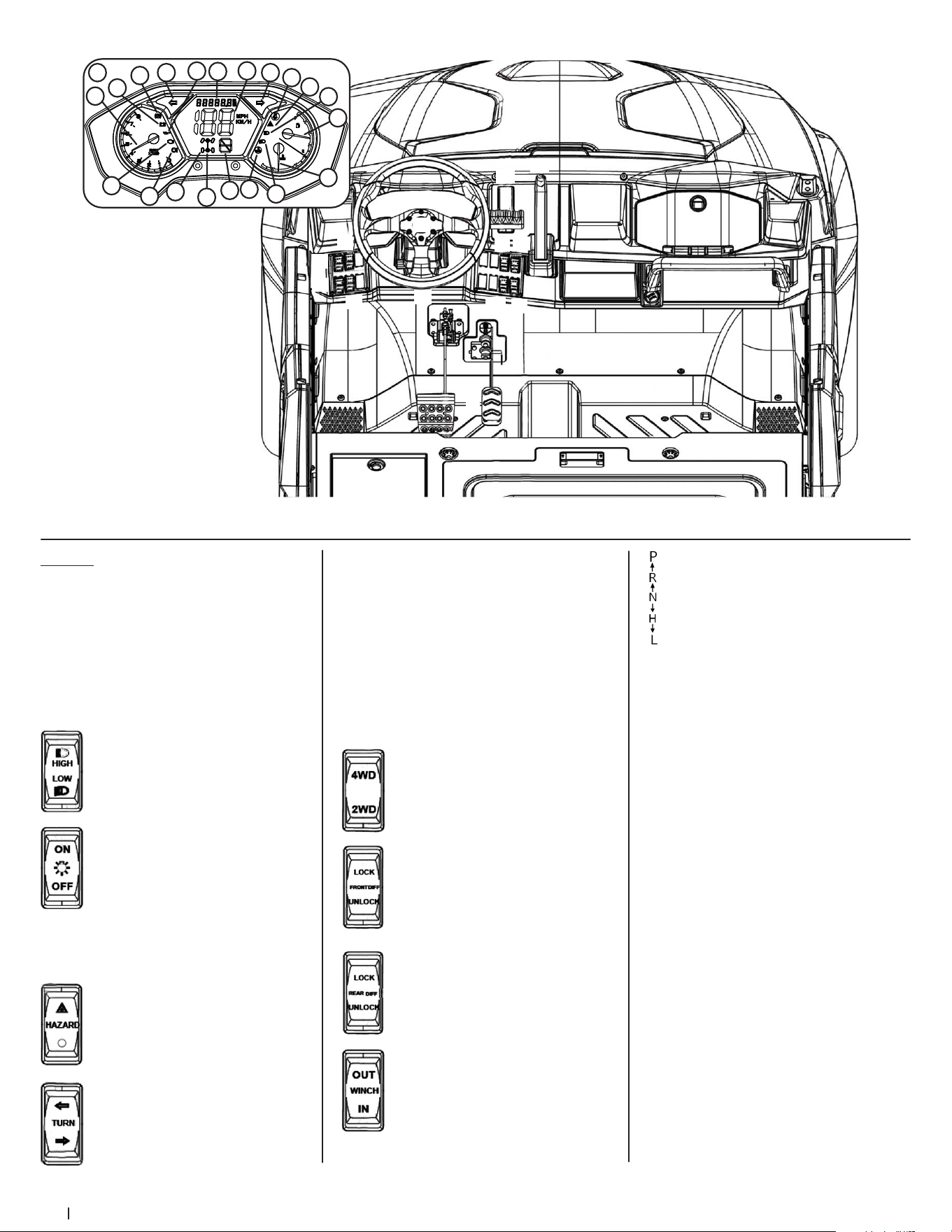
8 Section 4 — controlS & operation
(A)
(B)
(E)
(F)
(H)
(C)
(D)
(Q)
(I)
(J)
(K)
(N)
(L)
(M)
(O)
(P)
(G)
1
16
15
14
13
9
8
7
6
5
4
3
2
10
11
12
Q
20
19
18
17
Figure 4-2
Controls
Refer to Figure 4-2 for location and information of
the controls described below.
Steering Wheel (A)
The steering wheel is used to control the direction
of the utility vehicle.
Ignition (Not shown)
The Ignition is located on the right side of the
steering column.
High Beam Switch (B)
The high beam switch is used to turn
the high beams on the headlights “ON”
and “OFF.”
Headlight/Tail Light Switch (C)
The headlight/tail light switch turns the
headlights, instrument cluster lights and
tail lights “ON” and “OFF.”
Horn (D)
The horn activates the horn under the hood
when depressed.
Hazard Switch (E)
The hazard switch turns the hazards “ON”
and “OFF.”
Turn Signal Switch (F)
The turn signal switch controls the
turn signals and activates the LH or RH
turn signals.
Shift Lever (N)
The shift lever changes the gears of the utility
vehicle between PARK (“P”), REVERSE (“R”),
NEUTRAL (“N”), HIGH (“H”) and LOW (“L” ).
Parking Brake Lever (O)
The parking brake lever activates the utility
vehicle’s parking brake.
Glove Box (P)
The glove box is a small storage area in the dash on
the passenger side of the utility vehicle.
Instrument Cluster (Q)
The instrument cluster contains:
1 - Tachometer 11 - Differential Lock Indicator
2 - Parking Brake Indicator 12 - 2WD/4WD Indicator
3 - Battery Indicator 13 - Gear Indicator
4 - Oil Pressure Indicator 14 - Seat Belt Indicator
5 - Engine Indicator 15 - Hazards
6 - EPS System Fault * 16 - High Beam Indicator
7 - Left Turn Signal 17 - Fuel Gauge
8 - Right Turn Signal 18 - Coolant Temperature
9 - Hour Meter 19 - Low Beam Indicator
10 - Speedometer 20 - Coolant Over-
temp Indicator
* -- If equipped
12V Power Outlet (G)
The 12V power outlet is used for the convenience
of plugging in accessories that require a power
source with a maximum load of 5A at 12V.
Brake Pedal (H)
The brake pedal is used to slow down/stop the
utility vehicle.
Gas Pedal (I)
The gas pedal is used to control the speed of the
utility vehicle.
2WD/4WD Switch (J)
The 2WD/4WD switch is used to switch
between 2WD and 4WD.
Front Axle Differential Switch (K)
The front axle differential switch can
“LOCK” or “UNLOCK” the front
axle differential.
Rear Axle Differential Switch (L)
The rear axle differential switch
can “LOCK” or “UNLOCK” the rear
axle differential.
Winch Control (M)
The winch control releases cable on the
winch (“OUT”) or pulls the cable in (“IN”).
9Section 4 — controlS & operation
Operation
First 50 Hours
How a new vehicle is handled and maintained
determines the life of the vehicle.
A new vehicle just off the factory production line
has been, of course, tested, but various parts are
not fully aligned, so the operator should pay more
attention to operating the vehicle for the first
50 hours at a slower speed and avoid excessive
work or operation until the various parts become
“broken-in.” The manner to which you handle the
vehicle during the “breaking-in” period greatly
affects the life of your vehicle. Therefore, to obtain
the maximum performance and the longest life of
the vehicle, it is very important to properly break-
in your vehicle. For better handling a new vehicle,
the following precautions should be observed.
• Do not operate the vehicle at full speed for
the first 50 hours.
• Do not start quickly nor apply the
brakes suddenly.
• In winter, operate the vehicle after fully
warming up the engine.
• Do not run the engine at speeds faster
than prescribed.
• On rough roads, slow down to
suitable speeds.
• Do not operate the vehicle at fast speed.
The above precautions are not limited to new
vehicles. However, they should be especially
observed for new vehicles.
Note: The lubricating oil is especially important
for a new vehicle. Various parts need time to wear
and polish themselves to the correct operating
clearances. Small pieces of metal grit may develop
during the operation of the vehicle; and this
may wear out or damage the parts. Therefore,
change the lubricating oil a little earlier than
would ordinarily be required. For further details
of change interval hours, see the Product Care
section of this manual.
Starting the Utility Vehicle
WARNING
Seat belts reduce injury. Always wear your seat belts. The
lap-style seat belts may not provide adequate protection
for small children. Pay special attention when carrying a
child passenger. Always use the seat belts when operating
and riding in the vehicle.
General Safety
• RECEIVE INSTRUCTION — Entirely read
this operator’s manual. Learn to operate
this vehicle SAFELY. Do not risk INJURY or
DEATH. Allow only those who have become
competent in its usage to operate this
utility vehicle.
• Before starting the engine or beginning
operation, be familiar with the controls.
• Read the danger, warning and caution labels
located on the vehicle.
• To avoid the danger of exhaust fumes, do
not operate the utility vehicle in closed
buildings without proper ventilation.
• Start engine only from operator’s seat.
Never start the engine while standing
outside the utility vehicle.
• Make sure the shift lever is in the NEUTRAL
(N) or PARK (P) position before starting
the engine.
Starting the Engine
Note: Do not use starting fluid or ether.
Note: To protect the battery and the starter, make
sure that the starter is not continuously turned for
more than 5 seconds.
1. Engage the parking brake.
Note: The parking brake indicator is
illuminated when the parking brake is
applied and turns off when it is released.
See Figure 4-2.
2. Place the shift lever in the NEUTRAL (N) or
PARK (P) position.
Note: The engine will not start without the
gear shift in the NEUTRAL (N) or PARK (P)
position and the brake depressed.
3. Insert the key into the ignition and turn it to
the START position. Release the key when
the engine starts. See Figure 4-3.
K
E
Y
O
F
F
A
C
C
O
N
S
T
A
R
T
(D)
(C)
(B)
(A)
Figure 4-3
Note: The ignition is a 4-position switch,
the positions and brief descriptions of each
are below:
a. OFF — Engine is off and the key can
be removed.
b. ACC — Accessories such as radio are
on, but engine is off.
c. ON — Engine and all accessories
are on.
d. START — Starter motor on, the
key will return to the ON position
when released.
Note: When the ambient temperature is
below -15° C (5° F), the engine is very cold. If
the engine fails to start after 5 seconds, turn
off the key for 30 seconds and start again.
Stopping the Engine
1. After slowing the engine to idle, turn the key
to the OFF position.
2. Remove the key.
Warming Up
CAUTION
Be sure to set the parking brake during warm-up. Be sure to
set the shift lever to the PARK position during warm-up.
For 5 minutes after engine start-up, allow the
engine and transmission to warm up without
applying any load. This is to allow oil to reach
every engine part. If load applied to the engine
or transmission without warming up, damage
may occur.
Driving the Utility Vehicle
1. Adjust the seat belt to fit comfortably
around your lap, then buckle the seat belt.
WARNING
Do not operate the vehicle without the OPS in place and the
seat belt fastened securely around your waist and chest.
2. Start the engine as instructed in the Starting
the Engine section and make sure the front
wheels are turned to the desired direction
of travel.
CAUTION
Immediately stop the engine if the engine suddenly slows
down or accelerates, unusual noises are suddenly heard, or
exhaust fumes suddenly become very strong.
3. Push down on brake pedal, pull slightly back
on the parking brake lever while depressing
the lock button and then slowly push
forward to release the parking brake.
4. Push down on brake pedal and move the
shift lever into the desired setting. To avoid
damaging the transmission, depress the
brake pedal fully and make sure the vehicle
is completely stopped before shifting into
HIGH (H), LOW (L) or REVERSE (R).
WARNING
Do not stop or start suddenly when going uphill or downhill.
Be cautious when changing direction on slopes. Apply brakes
when going down slopes to maintain control of vehicle.
5. Release brake pedal and slowly apply
pressure to the gas pedal.
6. Release gas and apply brake pedal evenly
and firmly to slow down or stop.
2WD/4WD
CAUTION
When traveling at road speed, use only 2WD. When driving on
icy, wet, or loose surfaces, make sure the vehicle is correctly
loaded to avoid skidding and loss of steering control. Reduce
the speed and engage front wheel drive. Accident may
occur if the vehicle is suddenly braked, such as heavy towed
loads shifting forward causing loss of control. The braking
characteristics are different between two and four wheel
drive. Be aware of the differences and operate carefully.
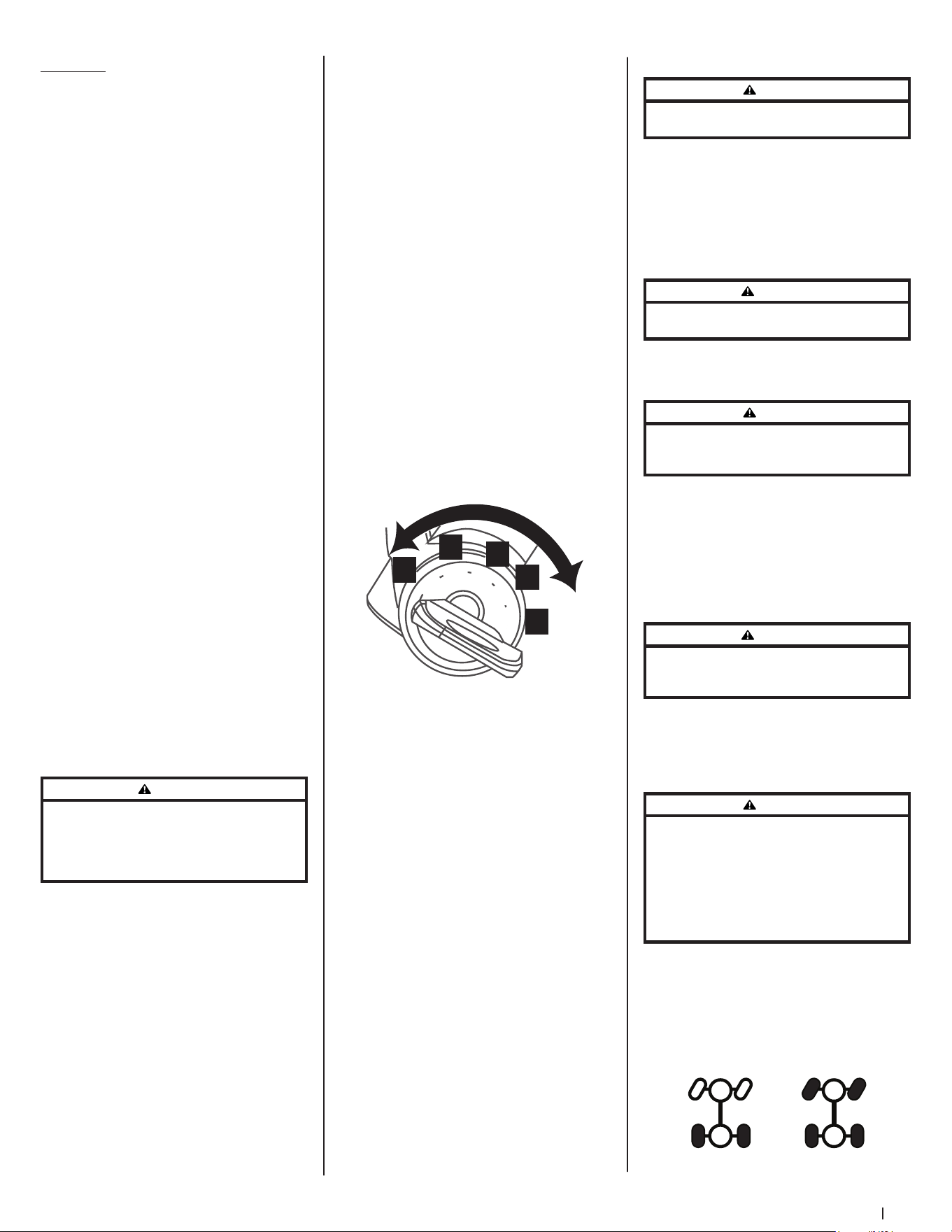
To activate the 4WD stop the utility vehicle and
press down on the upper half of the 2WD/4WD
switch. To return to 2WD, stop the utility vehicle
and press down on the lower half of the 2WD/4WD
switch. When in 2WD just the two rear tires will be
filled on the instrument cluster indicator, when in
4WD all four tires will be filled. See Figure 4-4.
2WD 4WD
Figure 4-4
10 Section 4 — controlS & operation
Differential Lock
WARNING
To avoid transmission damage, injury, or turf damage, drive
slow when operating utility vehicle with differential lock
engaged as steering response is noticeably reduced. Also,
do not drive the utility vehicle with the differential lock
engaged on concrete, asphalt, or any high traction surfaces.
The front and rear axle differentials can be
activated when the utility vehicle is stopped
and the shift lever is in the NEUTRAL position. To
activate either axle differential press the upper
portion of the front/rear axle differential switch.
To deactivate the axle differential press the lower
portion of the front/rear axle differential switch.
Both, one or neither of the differentials can
be active. When activated the differential lock
indicator display will show an “X” on the indicator
as shown in Figure 4-5.
X
X
X
X
OFF OFF
OFF
OFF
ON
ON
ON
ON
Figure 4-5
Important! Engage the differential as the last
option when stuck in mud or similar situation or
when the left and right side wheels are turning at
slightly different speeds.
Loading the Cargo Bed
WARNING
The utility vehicle may become unstable if the cargo bed
is loaded incorrectly. Avoid loose and unsecured loads or
uneven loading of material.
1. Verify cargo bed is securely latched
before loading.
2. Securely anchor all loads in cargo bed and
do not load beyond maximum capacity.
Note: The maximum box capacity is 500 lb
(227 kg).
3. When loading objects into cargo bed,
be sure load is securely anchored and
evenly distributed.
4. Do not load above height of cargo bed.
Load could shift forward striking driver or
passenger or cause driver to lose control
of vehicle.
5. Avoid loads which exceed physical
dimensions of cargo bed.
6. Avoid concentrated loads at rear or sides of
cargo bed. Be sure load is distributed evenly.
7. Reduce load and ground speed when
operating over rough or hilly terrain. Do
NOT overload vehicle. Limit loads to those
that can be safely controlled.
Raising & Lowering the Tailgate
To open up the tailgate (a), pull up on the tailgate
lever (b) and slowly lower the tailgate (a). To close
the tailgate (a) lift the tailgate (a) and push it
forward until it locks into place. See Figure 4-6.
(a)
(b)
Figure 4-6
Raising & Lowering the Cargo Bed (Dumping Load)
WARNING
To prevent the possibility of bodily injury from unintentional
lowering of the cargo bed, be sure vehicle is on a level and
stable surface and parking brake is set before raising cargo bed.
WARNING
A loaded cargo bed can be very heavy. Do not attempt to
dump a heavily loaded cargo bed.
1. Park the vehicle safely on level ground and
set parking brake.
2. Empty heavy loads by hand.
3. For light loads, unlatch cargo bed by pulling
up on one of the cargo bed release levers.
While holding the cargo bed release lever
lift the cargo bed. See Figure 4-7.
Figure 4-7
4. Once unloaded, lower the cargo bed and
securely latch it before operating the utility
vehicle. Do not drive the utility vehicle with
cargo bed in the raised position.
Towing Loads
WARNING
To help prevent personal injury due to loss of control or
tipping, always tow a load slow enough to maintain control.
1. Do not tow a load that exceeds 1200 lb (544
kg) rolling weight (i.e. trailer plus cargo) and
never exceed 110 lb (50 kg) tongue weight.
2. Go slow when towing a heavy load. Allow
for increased braking distance. Tow load at a
speed slow enough to maintain control.
3. Do not tow on slopes greater than 5°.
4. Be cautious when towing downhill, even
on a gradual slope or when turning. The
extra weight tends to push the tow vehicle
and may cause you to lose control (braking
and steering ability are reduced; towed
equipment may jack-knife).
Important! Extreme angles such as high
railroad crossings can place high bending
loads on hitch connection.
5. Do not modify the hitch in any way.
Loading a Utility Vehicle into a Truck or onto a Trailer
WARNING
Always park the truck or trailer in a flat area, set the parking
brake, turn the ignition off, and chock the wheels to prevent
any unexpected movement while loading the utility vehicle.
WARNING
Fully secure the loading ramps to the truck or trailer with
tie-down straps or cables to prevent the ramps from sliding
off while loading. Keep bystanders and/or helpers away
from ramps while loading.
Due to the overall size and dimensions, loading a
utility vehicle into a truck or onto a trailer is a task
that requires precision and the proper equipment
to be achieved safely. By following the steps
outlined below you’ll be able to select the proper
equipment to do the job and safely load and
unload your utility vehicle.
Determine if your truck or trailer is sufficient
for the task
Loading a utility vehicle into a truck or trailer that
can’t support its weight is extremely dangerous. It
is important that before any actual loading is done,
make sure your truck or trailer and loading ramps
are sufficient for loading and hauling the utility
vehicle. Here are some of the variables you need to
take into account:
• Length and Width: Measure the size of
your truck or trailer by taking width and
length measurements at the floor level.
Compare these measurements to the width
and length of your utility vehicle to make
sure it will fit comfortably.
• Weight Capacity: Making sure your truck or
trailer can handle the payload of your utility
vehicle is another critical task before any
loading is done. If using a truck, the payload
capacity must be a minimum of 3/4 ton. If
hauling on a trailer, remember that the towing
capacity of the vehicle will be reduced by the
added weight of the utility vehicle.
• Tailgate Considerations: If the payload
capacity is sufficient for hauling in a truck,
the last thing left to consider is your truck’s
bed length. Make certain that your truck
bed is long enough to allow the truck’s
tailgate to close completely when the utility
vehicle is loaded into the truck bed.
11Section 4 — controlS & operation
Choosing the proper loading ramp(s)
Choosing a reliable ramp and understanding how
to properly use it is far and above the best option
for safely loading a utility vehicle into your truck or
onto your trailer. Take a look at the considerations
you should have in mind when choosing the
proper ramp(s):
• Capacity: Utility vehicles are not evenly
balanced, meaning it’s necessary to check
the axle weights before you make any
choices regarding ramps. A typical ramp’s
capacity is based upon two axles with
equally distributed loads. We recommend
3000-lb minimum capacity ramp(s) as the
appropriate option for your two-person
utility vehicle.
• Offset Track Widths: Your utility vehicle
has an offset track width front and rear, it’s
important to factor this in to your ramp
placement and ramp width needs. Ramps
need to be wide enough to accommodate
the difference in the distances between the
front two wheels and the rear two wheels.
• Ground Clearance and Wheelbase:
Utility vehicles which have low ground
clearance (under 4”) and a relatively long
wheelbase (98” or more), make them prone
to bottoming out at the crest when using
straight ramps. As a solution to this issue we
suggest using arched ramps.
• Load Height: As with any ramp application,
the distance from the ground to the truck
bed or trailer impacts the overall length
of the ramp you will need, the greater the
load height, the longer the ramp should
be. Some ramp manufacturers and retailers
provide load height calculators to help you
determine the correct ramp length you will
need to safely load your vehicle.
Note: If you are still unsure of what types
of ramps you will need to get the job done
and are having trouble understanding these
instructions, check with your local ramp or
utility vehicle retailer for assistance.
Loading the Utility Vehicle
If your truck or trailer’s load capacity is sufficient
to transport the utility vehicle and you obtain the
proper loading ramps and equipment to safely
secure the utility vehicle to the truck or trailer, the
only thing left to do is load it. Here’s how to best
accomplish this task:
1. Proceed with extreme caution. It is very
difficult to overcome a mistake while in the
loading process.
2. Park the truck or trailer in a flat area, set
the parking brake, turn the ignition off and
chock the wheels.
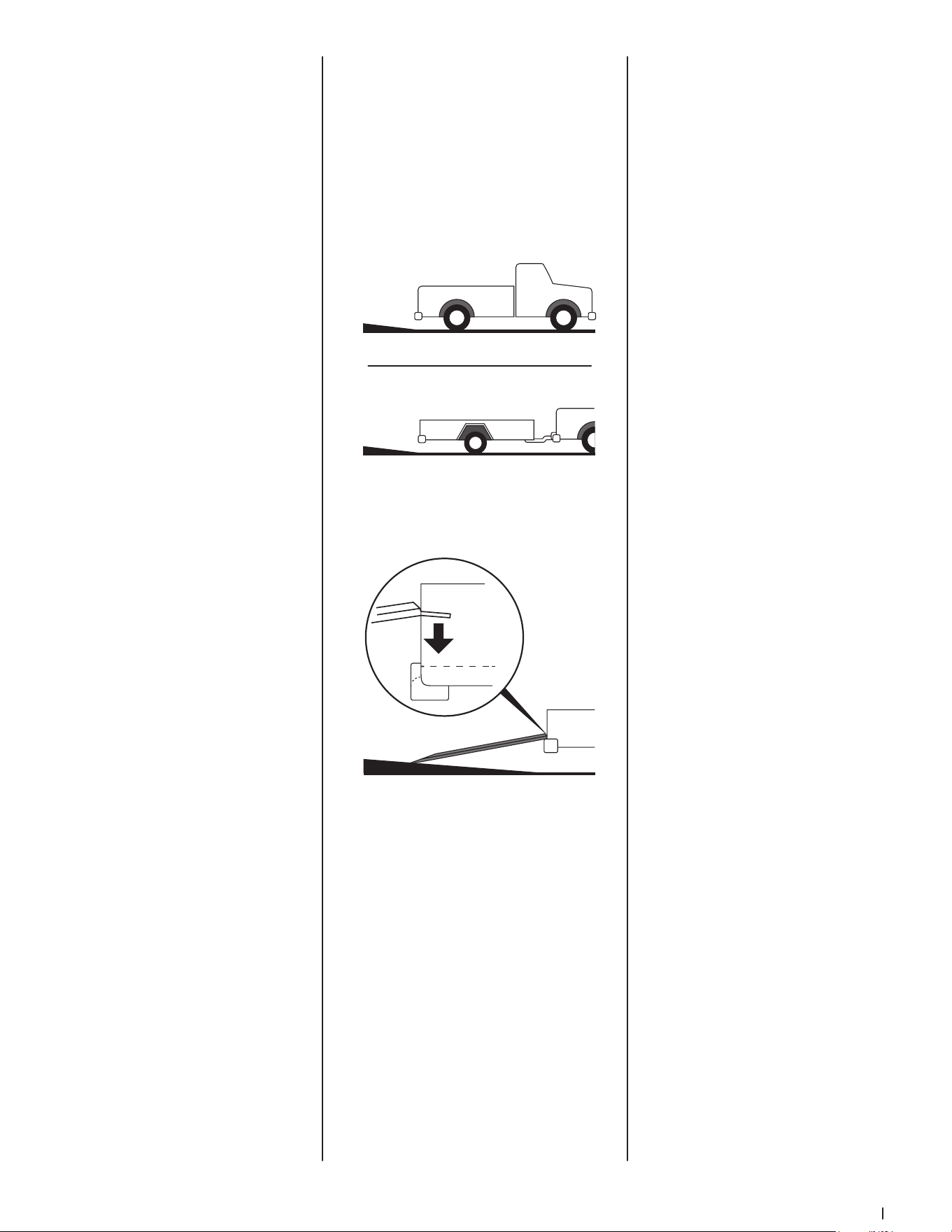
3. Face the truck bed or trailer towards a slight
incline, which will reduce the steepness of
the loading angle by bringing the bottom
of the ramps up on the slight incline. See
Figure 4-8.
Figure 4-8
4. Place the ramp fingers or plate edges on the
edge of the trailer or truck bed. See Figure 4-9.
Figure 4-9
5. Use tie-down straps or cables to secure the
ramps to the trailer or truck, via the bumper
(steel bumpers only) or trailer hitch safety
chain loops. Refer to instructions provided
with the ramp.
6. If your utility vehicle is supplied with a
roof and/or windshield, remove or fully
secure them prior to loading. Roofs and
windshields are not designed to withstand
the wind speeds that the open road can
generate, so it’s best to remove them
entirely to prevent any damage or accidents.
7. Follow all safety rules provided in this
manual along with the manuals supplied by
the trailer and ramp manufacturer. Carefully
load the utility vehicle onto the truck
or trailer.
8. Once the utility vehicle is on the truck or
trailer, set the utility vehicle’s parking brake
and secure the utility vehicle to the truck
or trailer. Tie-down strap placement will
depend on your truck or trailer. Be sure
to use only tie-down straps sufficient for
the load capacity. If loaded onto a truck,
close the tailgate once the utility vehicle is
secured to the truck bed.
9. Stop periodically to ensure that your tie-
down straps have not loosened and that the
utility vehicle remains securely in place.
Important! Know the total height of your
vehicle with the utility vehicle loaded
before transporting. Be sure to check
for low clearance bridges, doorways, etc.
prior to traveling under them. The added
height above the height of your truck could
cause clearance issues and damage to
both vehicles.

Product Care
5
12
Maintenance Chart
Intervals
Items
First 20
hours
First 50
hours
Every 50
hours
Every 100
hours
Every 150
hours
Every 200
hours
Every 300
hours
Every 500
hours
Every 3900
hours
Every year
Every
2 years
Every
4 years
Grease utility vehicle
PP
Clean muffler/spark arrestor
PP PP
Clean spark arrestor
PP
Check lug nuts
PP PP
Check battery condition
PP
Adjust front wheel toe-in
PP
Change oil
PP PP
Check fuel line
PP PP
Replace fuel line
PP
Clean air filter element *
PP PP PP
Check brake pedal
PP PP
Adjust parking brake
PP PP PP
Check brake light switch
PP PP
Check radiator hose & clamp
PP
Replace radiator hose & clamp
PP
Check PCV Accumulator
PP PP
Check intake air line
PP
Replace intake air line
PP
Check brake hose & pipe
PP PP
Replace brake hose & pipe
PP
Check tires
PP PP
Change axle case oil
PP
Adjust engine valve clearance
PP
Check fuel injection
PP
Check injection
PP
Check CV shaft boots
PP
Check exhaust system
PP
Check wheel bearings
PP PP
Check engine timing
PP
Change brake fluid
PP
Replace remote hydraulic hose
PP
Replace rear brake cylinder seal
PP
Replace front brake cylinder seal
PP
Flush cooling system
PP
Change engine coolant
PP
* — Perform more often in dusty conditions.
13Section 5 — Product care
Troubleshooting
1. Engine will not start:
• Battery has low voltage
• Loose or corroded battery connections
• Fuse is blown
• Spark plug wire is loose
or disconnected
• Faulty spark plug or coil
• No fuel or improper fuel
• Plugged fuel filter
• Defective starter solenoid
• Open-circuit in wiring
2. Engine is difficult to start:
• Engine is cold
• Plugged fuel filter
• Engine oil viscosity too heavy
• Spark plug is fouled
• Faulty spark plug or wire
• Loose or corroded
electrical connections
• Stale or improper fuel
3. Engine misfires under load:
• Faulty spark plug
• Stale or dirty fuel
• Plugged fuel filter
• Faulty coil or wire
4. Engine does not restart when warm:
• Poor quality fuel
• Very hot weather conditions
• Fuel tank vent plugged
• Dirt in fuel filter
5. Entire electrical system does not work:
• Blown fuse
• Loose or corroded connections
• Dead or faulty battery
6. Dead battery:
• Shorted starter solenoid
• Key switch not turned to
STOP position
• Faulty battery
7. Battery will not take a charge:
• Dead battery
• Loose or corroded connections
8. Difficult to shift:
• Idle speed too fast
• Gears not lined up. Tap throttle
and let it return to idle. If still hard
to shift, contact your nearest
authorized service dealer
9. Indicator lights do not come on when key
switch is in START position:
• Faulty bulb
• Faulty wiring
• Faulty sensor
10. Engine runs unevenly:
• Loose electrical connections
• Choke (if equipped) or throttle
cable sticking
• Fuel line or fuel filter plugged
• Stale or dirty fuel
• Check the joint boots on the drive shaft for
damage. If the joint boots are damaged, see
an authorized service dealer.
• Check tire pressure. See Tire Pressure in
this section.
Maintenance
WARNING
To avoid personal injury, be sure to check and service the
vehicle on a flat surface with the engine off and the parking
brake ON. If servicing under the cargo bed, be sure that the
cargo bed is supported so that it can not inadvertently close.
Do not touch muffler or exhaust pipes while they are hot;
Otherwise, severe burns could result.
WARNING
If vehicle diagnosis requires the vehicle to be run with the
wheels off the ground, the free wheeling state will cause
the engine management system to create a lean condition.
This lean condition will cause the exhaust system to become
hotter than normal operating conditions. Exercise extreme
caution when working around the exhaust components and
allow extra time for the exhaust components to cool.
Tire Pressure
The recommended operating tire pressure is
14 psi (70 kPa) for all tires. Over-inflating above
recommended tire pressure can reduce the life of
the tire. Check tire pressures before each use.
Note: If the cargo bed is at maximum capacity
(1000 lbs), the rear tire pressure can be increased
to 18 psi (124 kPa).
Lug Nuts
Check torque of lug nuts after first 50 hours of use
and every 100 hours thereafter. Tighten lug nuts in
a diagonal pattern. Torque lug nuts to 65-75 lb-ft
using a torque wrench.
Removing the Hood & Interior Hood Panel
CAUTION
To avoid personal injury from contact with moving parts never
open operator’s seat or hood cover while the engine is running.
To open the hood, pull up on the center of the
upper edge of the cover (a) and lift the hood off.
To close, insert the front bottom hooks into the
hood. Push down on the perimeter of the cover.
See Figure 5-1.
(a)
Figure 5-1
• Improper fuel
• Air cleaner element plugged
• Spark plug is fouled
11. Engine overheats:
• Air cleaner element missing
or plugged
• Air intake plugged
• Engine oil low
• Engine operated too long at slow
engine speed
• Cooling fan not turning
12. Engine loses power:
• Engine overheating
• Too much oil in engine
• Faulty spark plug
• Fuel supply being restricted
• Fuel filter plugged
• Fuel line pinched or kinked
• Fuel pump output not adjusted
to specification
• Improper fuel
• Air cleaner element plugged
13. Starter does not work:
• Loose or corroded connections
• Low battery output
• Dead or faulty battery
• Faulty starter
14. Starter cranks slowly:
• Low battery output
• Dead or faulty battery
• Engine oil too heavy
• Loose or corroded connections
15. Battery light comes on when engine
is running:
• Low engine speed
• Faulty voltage regulator
• Faulty battery
• Faulty rotor or stator
• Damaged wiring harness
16. Vehicle will not move:
• Shift Lever still in NEUTRAL
• Parking Brake still set
• Broken or cut drive belt
• Safely check to see if the vehicle
will go in reverse and then try to
go forward. If vehicle still will not
move forward, contact your nearest
authorized dealer
Pre-Start Checklist
• Check parking brake. Make sure the parking
brake indicator light comes on when the
parking brake is ON.
• Inspect the instrument panel for broken
gauges and warning lamps.
• Check the headlights and turn signals.
Replace if broken.
• Check seat belt and OPS. Do not operate
utility vehicle until repaired if either
is broken.
14 Section 5 — Product care
To remove the interior hood panel (a), grasp
the upper left corner of the panel and pull. See
Figure 5-2.
(a)
Figure 5-2
Removing the Seat
To remove the seat, lift up on the front edge of the
seat and after the two pins (a) clear the bushings
pull towards the front of the vehicle. See Figure
5-3. When re-installing the seat, make sure the
pins (a) in the seat are inserted into the holes (b) in
the frame.
(a)
(a)
(b)
(b)
Figure 5-3
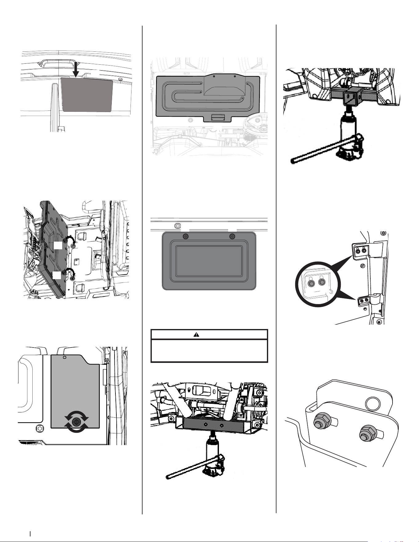
Removing the Battery Access Panel
Unlock the battery access panel under the seat
by rotating the lock knob, then lifting the battery
access panel. See Figure 5-4.
(a)
Figure 5-4
Removing the Engine Access Panel
Lift up on the handle (a) near the front of the
engine access panel under the seat, then remove
the engine access panel. See Figure 5-5.
(a)
Figure 5-5
Removing the Air Filter Access Panel
Remove the two screws (a) securing the air filter
access panel (b) to the front of the seat box. See
Figure 5-6.
(a)
(b)
(a)
Figure 5-6
Jacking Up the Utility Vehicle
WARNING
To avoid personal injury, death, or vehicle damage do not
work under the vehicle unless it is secured by safe stands or
suitable blocking.
1. Jack up the front end of the utility vehicle on
the front frame tube (a) only. See Figure 5-7.
(a)
Figure 5-7
2. Jack the rear of the utility vehicle only after
placing a wooden block under the right
(a) and left frame tube (b) for securing the
engine and then supporting it. Do not apply
jack pressure on the steel plate directly
under the engine. See Figure 5-8.
(a)
(b)
Figure 5-8
Adjusting the Doors
If the gaps around the doors are uneven, the
door can be adjusted. To adjust the doors, loosen
the two bolts (a) on each hinge, adjust the door
until an equal gap is achieved all the way around.
Retighten all four bolts (a). See Figure 5-9.
(a)
(a)
Figure 5-9
If the door is not latching properly, the latches (a)
can be adjusted. Loosen the two bolts (b) securing
the latch (a), position the latch (a) so that the door
closes and latches properly, then re-tighten the
two bolts (b). See Figure 5-10.
(a)
(b)
(b)
Figure 5-10

15Section 5 — Product care
Checking & Refilling Fuel
CAUTION
Do not smoke while refueling. Be sure to stop the engine
before refueling.
1. Turn the key switch to ON, check the
amount of fuel by the fuel gauge.
2. Fill fuel tank when fuel gauge shows 1/4 or
less fuel in the tank.
3. The fuel tank holds approximately 7.4
gallons (28 L) of fuel.
Checking & Adding Oil
Important! If oil level is low, do not run the engine.
1. Park the vehicle on a flat surface with
engine off, remove the seat and engine
access panel to access the engine.
2. To check the oil level, remove the dipstick (a),
wipe it clean, replace it without re-threading
the dipstick, and pull it out again, check to
see if the level is too low and add new oil to
the full level on the dipstick (a). See Figure
5-11 for the location of dipstick.
(a)
Figure 5-11
3. After the new filter has been replaced,
the engine oil normally decreases a little.
Make sure that the engine oil does not leak
through the seal and check the oil level on
the dipstick. Add oil if necessary.
4. See Figure 5-12 for oil recommendations.
SAE 0W-30
SAE 10W-30
SAE 10W-40
SAE 20W-50
SAE 15W-40
SAE 20W-40
Figure 5-12
CAUTION
Only use engine oil with API Service Classification of SJ or
Higher and JASO-MA Grade.
5. The engine oil capacity is 2.22 quarts (2.1 L).
Checking & Adding Engine Coolant
CAUTION
Do not remove radiator cap while coolant is hot. When
cool, slowly rotate to the first stop and allow sufficient
time for excess pressure to escape before removing the
cap completely.
1. Park the vehicle on a flat surface, remove
the hood panel, set the parking brake and
shut off the engine.
2. Check to see that the coolant level is
between the FULL (a) and LOW (b) marks of
recovery tank (c). See Figure 5-13.
(a)
(b)
(c)
Figure 5-13
3. When the coolant level drops due to
evaporation, add water only up to the FULL
(a) level. In case of leakage add anti-freeze
and water in the specified mixing ratio up to
the FULL (a) level. (See Flushing the Coolant
System and Changing Coolant section).
• Use clean fresh water and anti-freeze
to fill the recovery tank.
• If water should leak, consult your
local authorized service dealer.
Note: If the radiator cap has to be removed,
follow the cautions above and securely
retighten the cap.
Cleaning the Radiator Screen
CAUTION
Be sure to stop the engine before removing the screen.
Note: Radiator screen must be cleaned of debris to
prevent engine from overheating.
1. Park the utility vehicle on a flat surface.
2. Remove the radiator cover.
3. Detach the screen and clean the radiator and
radiator screen and radiator fins of all debris.
See Figure 5-14.
Figure 5-14
Checking & Adding Brake Fluid
CAUTION
Never operate the vehicle if the brake fluid is below the
minimum mark. Use only DOT3 from a sealed container.
Other types of brake fluid may ruin synthetic resin or rubber
installed in brake system components and may cause brake
failure. Avoid contamination of the brake fluid, thoroughly
clean around the filler cap before removing. Do not open
the brake fluid reservoir cap unless absolutely necessary.
Use extreme care when filling the reservoir. If brake fluid
spills on coolant hose, wash off with water immediately, as
brake fluid quickly ruins synthetic resin or rubber hoses.
1. Check to see that the brake fluid level of the
brake fluid reservoir (a) is up to the MIN (b)
level. See Figure 5-15.
(a)
(c)
(b)
Figure 5-15
2. If it is below the MIN (b) level add brake
fluid, but do not exceed the MAX (c) level.
Checking the Brake Pedal
WARNING
Stop the engine and chock the wheels before checking
brake pedal.
Inspect the brake pedals for free play (a), pedal
stroke (b) and smooth operation. Refer to
Figure 5-16.
(a)
(b)
Figure 5-16
1. Release the parking brake.
2. Step on the pedal and measure the free
play (a). There should be between .3” and
.5” (7-14 mm) of free play (a). If the free
play (a) measurement is outside of these
specifications, see an authorized service
dealer to have the brake adjusted.
16 Section 5 — Product care
3. Step on the pedal and measure the stroke
(b). There should be less than 4.7” (120 mm)
of stroke (b). If the measurement is outside
of these specifications, see an authorized
service dealer to have the brake adjusted.
Checking & Adjusting the Parking Brake
Pull the parking brake to apply the brakes with
the key switch in the ON position and the parking
brake indicator should come on. To release the
parking brake, depress the parking pedal. Make
sure the parking brake warning lamp on the
display goes off when parking brake is OFF.
If the parking brake is in need of adjustment,
proceed as follows:
1. Locate the parking brake adjustment nut
near the engine. See Figure 5-17.
(a)
(b)
Figure 5-17
2. Loosen the lock nut (a) and then tighten the
bolt (b) to adjust the parking brake. Turn
the bolt until it touches, then back it off a
1/4-turn. See Figure 5-17.
If there is play in the parking brake handle there is
a secondary adjustment that can be performed.
1. Look inside the driver’s side wheel well and
locate the adjustment point. Slide back the
rubber cover (a) on the adjustment nuts (b).
See Figure 5-18.
(a)
(b)
Figure 5-18
2. Adjust the parking brake handle nuts (b)
until the free play in the handle is gone. See
Figure 5-18.
Checking & Adjusting the Shift Lever
If the shifter and the display image on the
instrument cluster do not match or the utility
vehicle is not shifting, a shift cable adjustment can
be performed.
1. Remove the hood and the interior hood panel.
2. Locate the shift lever adjustment nuts (a).
See Figure 5-19.
(a)
Figure 5-19
3. Adjust the nuts (a) up or down until the shift
lever is working properly. See Figure 5-19.
Checking the Engine Start System
WARNING
Do not allow anyone near the vehicle while testing. If the
vehicle does not pass the test, do not operate the vehicle.
1. Sit on the operator’s seat.
2. Place the shift lever in the NEUTRAL position.
3. Set the parking brake and stop the engine.
4. Move the shift lever to: LOW, HIGH, PARK
or REVERSE position. Do not step on the
brake pedal.
5. Turn the key to START position.
6. The engine should not crank.
7. If it cranks see an authorized service dealer.
8. Repeat Steps 4 and 5 but when turning the
key to start position step on the brake pedal.
The engine should crank.
9. If it does not crank see an authorized
service dealer.
Adjusting the Shocks
There are three adjustment points on the shocks.
The rebound (a), pre-load spring (b) and damping
rate (c) can be adjusted. Refer to Figure 5-20 for the
following instructions.
C
F
a
s
t
S
l
o
w
F
S
(a)
(b)
(c)
Figure 5-20
Rebound Adjuster (a)
The rebound adjuster is located near the bottom
of the shock and controls the “bounce back” speed
of the utility vehicle. To adjust the rebound or
“bounce-back” speed, follow the steps below:
Note: Each position has a stop or “click” to indicate
the setting.
1. Insert a standard screw driver into the
adjustment.
2. Rotate the screw into one of the 18 positions
between “S” (position 0) and “F” (18). Rotate
the screw clockwise (towards the “S” or “0”
position) to slow the rebound and counter-
clockwise (towards the “F” or “18” position)
to speed up the rebound.
Pre-Load Spring Adjuster (b)
The pre-load adjuster is located in the body of
the shock and controls the height of the vehicle.
It can be adjusted to accommodate for different
load situations.
Note: This adjustment requires a spanner wrench
to complete. A spanner wrench is included in the
tool kit shipped with this utility vehicle.
1. Using a spanner wrench, loosen the upper
lock nut.
2. Adjust the pre-load adjuster nut to the
desired setting. Turn the pre-load adjuster
clockwise to increase the compression
force (raise the utility vehicle) and turn the
pre-load adjuster nut counter-clockwise to
decrease the compression force (lower the
utility vehicle).
Damping Rate Adjuster (c)
The compression adjuster is located on the upper
part of the shock and controls the ride of the utility
vehicle and the impact resistance of the shocks.
Note: Each position has a stop or “click” to indicate
which of the 18 positions it is in.
1. To increase the stiffness of the suspension
and increase the absorption of impacts,
rotate the compression adjuster screw
clockwise towards the “SLOW” (or
“0”) position.
2. To decrease the stiffness (soften the ride)
rotate the compression adjuster screw
counter-clockwise towards the “FAST” (or
“18”) position.
To return the utility vehicle to its stock setting, use
the chart below:
Rebound
Adjuster
Pre-Load
Adjuster
Compression
Adjuster
Front Position 7 295 mm Position 5
Rear Position 4 300 mm Position 3
* -- These settings are based on a “full load”
condition. 250 lb (113 kg) driver, 250 lb (113 kg)
passenger and 500 lb (227 kg) cargo load.
Service
WARNING
To avoid personal injury, be sure to check and service the
vehicle on a flat surface with the engine off and the parking
brake ON. If servicing under the cargo bed, be sure that the
cargo bed is supported so that it can not inadvertently close.
Do not touch muffler or exhaust pipes while they are hot;
Otherwise, severe burns could result.
Changing the Oil
WARNING
Be sure to stop the engine before replacing oil. Allow engine
to cool down sufficiently, oil can be hot and can burn.
1. Park the vehicle on a flat surface and raise
the cargo bed.
2. To drain the used oil, remove the drain plug
at the bottom of the engine and completely
drain the oil into an oil pan.
3. After draining, reinstall the drain plug.
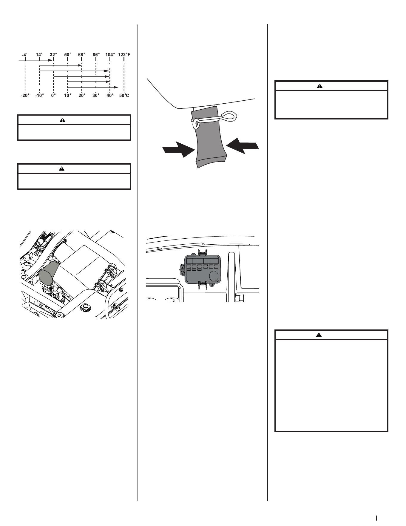
17Section 5 — Product care
4. Fill with the new oil up to the upper notch
on the dipstick.
5. See Figure 5-21 for oil recommendations.
SAE 0W-30
SAE 10W-30
SAE 10W-40
SAE 20W-50
SAE 15W-40
SAE 20W-40
Figure 5-21
CAUTION
Only use engine oil with API Service Classification of SJ or
Higher and JASO-MA Grade
6. The engine oil capacity is 2.22 quarts (2.1 L).
Replacing Oil Filter
WARNING
Be sure to stop the engine before replacing oil filter. Allow
engine to cool down sufficiently, oil can be hot and can burn.
1. Park the vehicle on a flat surface, remove
the seat and open the engine access cover.
2. Make sure the engine is warm.
3. Remove the oil filter (a). See Figure 5-22.
(a)
Figure 5-22
4. Put a film of clean engine oil on the rubber
seal of the new filter.
5. Tighten the filter until it contacts the
mounting surface.
6. Tighten filter by hand an additional 1/2-
turn only.
Draining the PCV Accumulator
The PCV accumulator should be drained at each
oil change to remove oil condensation. There are
two PCV accumulators, one near the front of the air
intake box and one near the rear. To drain the PCV
accumulator, pinch the valve at the bottom of the
tube and allow the condensation to run out. See
Figure 5-23.
Figure 5-23
Replacing Mini Fuses
The mini fuses are intended to protect the
electrical system. If any of them have blown out,
be sure to pinpoint the cause. (See Specifications
section, Figure 6-1 for fuse box layout.)
1. Disconnect the negative battery cable.
2. Open the mini fuse box cover. See Figure 5-24.
++ ++ ++ ++ ++ ++
++ ++ ++ ++ ++ ++
++ ++ ++ ++ ++ ++
++ ++ ++ ++ ++ ++
++ ++ ++ ++ ++ ++
++ ++
++ ++
++ ++
++ ++
303025
10
15
10
5
15
5
10 51 5
10 15 10
Figure 5-24
3. Pull out the mini fuse.
4. Insert a new mini fuse into the box.
5. Close the mini fuse box cover.
6. Re-connect the negative battery cable.
Changing the Front & Rear Axle Case Oil
See your authorized service dealer to have the axle
case oil changed.
Changing the Brake Fluid
See your authorized service dealer to have the
brake fluid changed.
Replacing Radiator Hose
See your authorized service dealer to have the
radiator hose changed.
Replacing Fuel Hose
See your authorized service dealer to have the fuel
hose changed.
Replacing Brake Master Cylinder
See your authorized service dealer to have the
brake master cylinder changed.
Replacing Front Brake Seal
See your authorized service dealer to have the
front brake seal changed.
Replacing Rear Brake Cylinder Seal
See your authorized service dealer to have the rear
brake seal changed.
Replacing Intake Air Line
See your authorized service dealer to have the air
intake line changed.
Replacing Brake Hose
See your authorized service dealer to have the
brake hoses changed.
Flushing the Coolant System & Changing Coolant
CAUTION
Do not remove radiator cap while coolant is hot. When
cool slowly rotate to the first stop and allow sufficient
time for excess pressure to escape before removing the
cap completely.
1. Stop the engine and let it cool down.
2. To drain the coolant, open the radiator drain
plug and remove radiator cap. The radiator
cap must be removed to completely drain
the coolant.
3. After all coolant is drained, close the drain plug.
Note: Do not start engine without coolant.
4. Fill with clean water and cooling
system cleaner.
5. Follow directions of the cleaner container.
6. After flushing, fill with clean water and anti-
freeze until the coolant level is just below
the radiator cap.
Note: When the antifreeze is mixed with
water, the antifreeze mixing ratio must be
50-50. See the Antifreeze section.
7. Install the radiator cap securely. If the cap is
loose or improperly fitted, water may leak
out and the engine could overheat.
8. Fill with fresh water/antifreeze up to the
“FULL” mark on the recovery tank. See
Figure 5-13.
9. Start and operate the engine for a
few minutes.
10. Stop the engine and let cool.
11. Check coolant level of recovery tank and
coolant if necessary.
12. Burp (remove air from) the coolant system
as instructed in the Burping (Removing Air
From) the Coolant System section.
Anti-Freeze
WARNING
When using antifreeze, put on some protection such as
rubber gloves. (Antifreeze contains poison.) If you should
drink antifreeze, throw up at once and seek medical
attention. If antifreeze comes in contact with the skin or
clothing, wash it off immediately. Do not mix different
types of antifreeze. The mixture can produce a chemical
reaction between substances. Antifreeze is extremely
flammable and explosive under certain conditions. Keep
fire away from antifreeze. Keep children away from
antifreeze. When draining fluids from the engine, place
some container underneath the engine body. Do not
pour waste onto the grounds, down a drain or into any
water source. Also, observe the relevant environmental
protection regulations when disposing of antifreeze.
If it freezes, coolant can damage the cylinders and
radiator. If the ambient temperature falls below
0° C (32° F) or before a long-term storage, let out
coolant completely, or mix fresh water with long-
life coolant and fill the radiator and recovery tank
with the mixture.
1. Long-life coolant comes in several types.
Use an ethylene glycol (EG) type for
this engine.
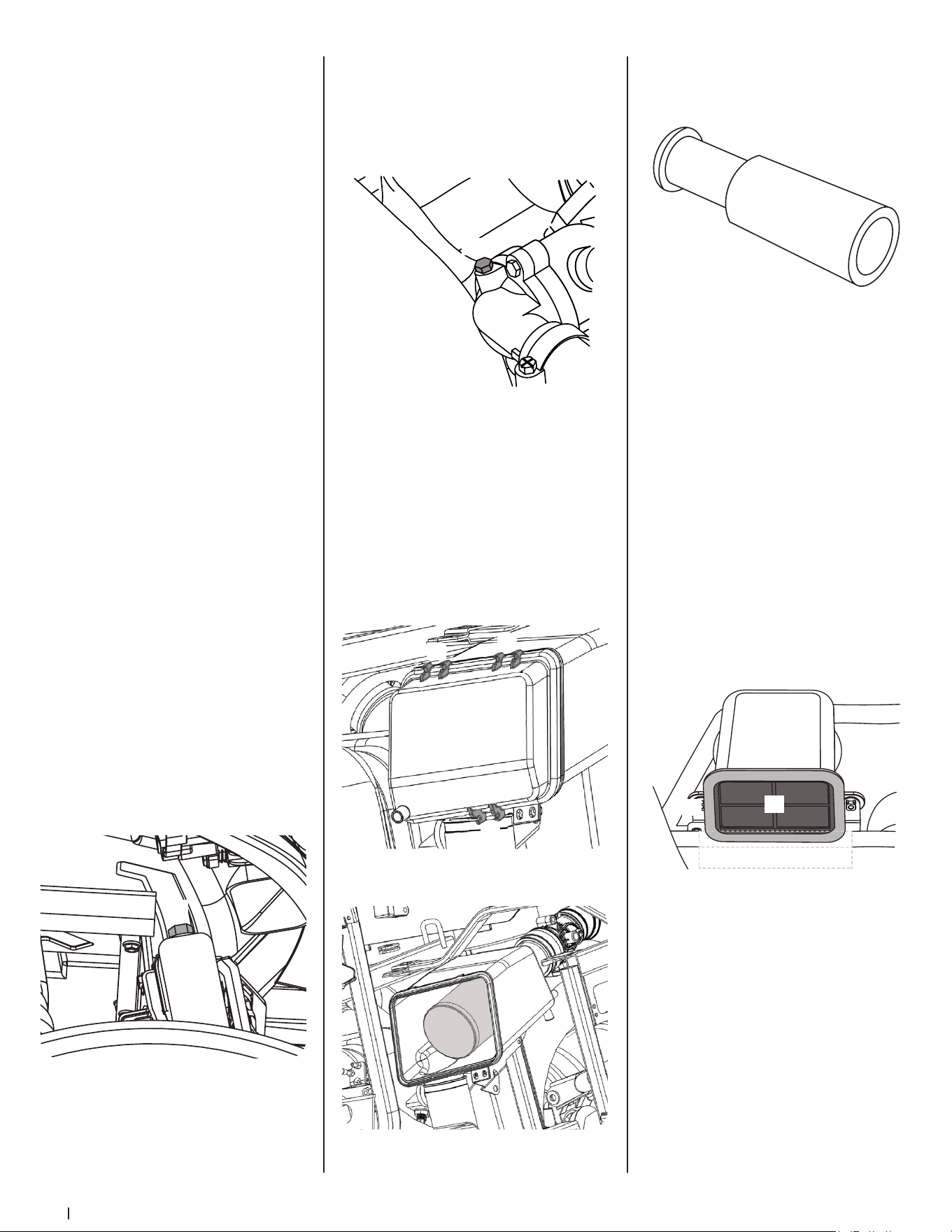
18 Section 5 — Product care
2. Before employing long-life coolant-mixed
cooling water, fill the radiator with fresh
water and empty it again.
3. Repeat this procedure two or three times to
clean up the inside.
4. Mix the long-life coolant.
5. The procedure for the mixing of water
and antifreeze differs according to the
make of the antifreeze and the ambient
temperature. Refer to SEA J1034 standard,
more specifically also to SAE J814c.
6. Add the long-life coolant.
7. If there is a mixture leak, add long-life
coolant from the same manufacturer and
type in the same mixture percentage.
Note: Never mix long-life coolant from
different manufacturers. (Different brands
may have different additive components,
and the engine may fail to perform
as specified.)
8. When the long-life coolant is mixed, do not
employ any radiator cleaning agent. The
long-life coolant contains anticorrosive
agent. If mixed with the cleaning agent,
sludge may build up, adversely affecting the
engine parts.
9. The utility vehicle’s genuine long-life
coolant has a service life of 2 years. Be sure
to change the coolant every 2 years.
10. Burp (remove air from) the coolant system
as instructed in the Burping (Removing Air
From) the Coolant System section.
Burping (Removing Air From) the Coolant System
To “burp” the coolant system, proceed as follows:
Note: When re-filling the coolant system, this
procedure should be performed every time to
avoid an overheating risk.
1. Chock the rear wheel, engage the parking
brake place the shift lever in NEUTRAL or
PARK and jack up the front of the utility
vehicle approximately 6”.
2. Remove the bleeder screw (a) on the
radiator, fill the radiator and when fluid
begins to come out of the bleeder screw
hole, replace the bleeder screw (a). The
bleeder screw (a) can be accessed via the
front right wheel well. See Figure 5-25.
(a)
Figure 5-25
3. Start the utility vehicle and let it idle.
4. Remove the second bleeder screw (a) where
the radiator hose (b) connects to the engine
and let the engine run until a steady stream
of fluid comes out of the bleeder screw
(a) hole indicating there are no more air
pockets in the coolant system. Replace the
bleeder screw (a). See Figure 5-26.
(a)
(b)
Figure 5-26
5. Top off the radiator and replace the radiator
cap. Then lower the front of the utility
vehicle off the jack.
Cleaning Primary Air Filter Element
Open the air cleaner cover once a week under
ordinary conditions — or daily when used in a dusty
place — to get rid of large particles of dust and dirt.
Note: Do not run the engine with filter element
removed.
1. Remove the air filter access panel.
2. Remove the air filter cover (a) from the three
air filter cover holders (b). See Figure 5-27.
(a)
(b)
(b)
(b)
Figure 5-27
3. Remove the air filter element. See Figure 5-28.
Figure 5-28
4. Remove the inner filter (a) from the paper
element (b). See Figure 5-29.
(a)
(b)
Figure 5-29
5. Clean the paper element with a soft brush
or low pressure air. Be careful not to damage
the paper pleats during cleaning.
6. Inspect the inner filter for deposits or damage.
7. If either filter are excessively dirty or
damaged, replace filters as a set.
8. Re-install the primary air filter element.
9. Install the air filter case cover and be sure
the crankcase breather hose is connected.
Note: Be sure to refit the air filter cover with
the arrow (on the rear of air filter cover)
upright. If the air filter cover is improperly
fitted the evacuator valve will not function
and dust will adhere to the air filter element.
Cleaning the Air Intake
Air Intake Screen
1. Remove the hood and locate the air intake.
2. Remove the rubber seal (b) around the front
of the air intake (a) and remove the air intake
screen (c). See Figure 5-30.
(a)
(b)
(c)
Figure 5-30
3. Rinse the air intake screen (c) with water and
replace the air intake screen (c) and rubber
seal (b). See Figure 5-30.
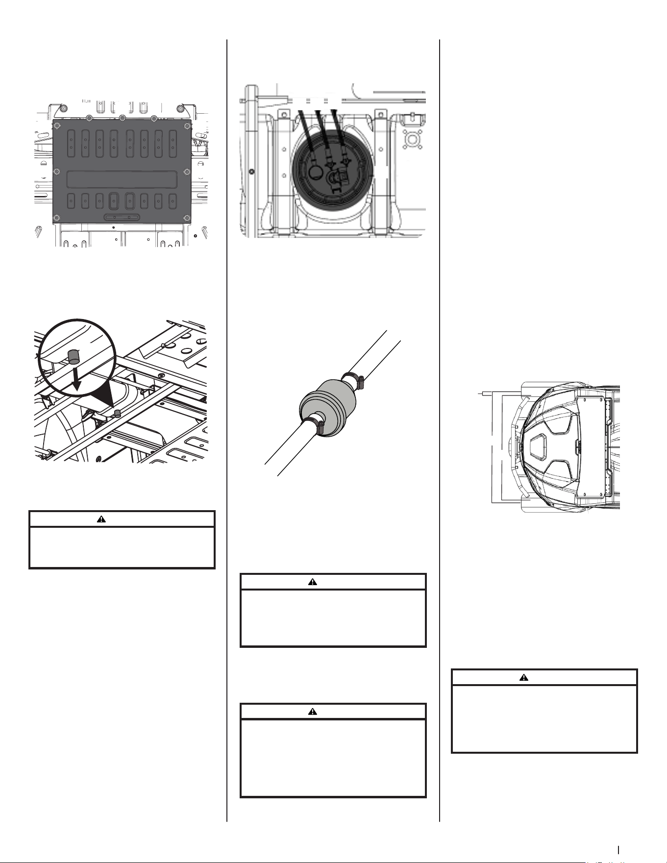
19Section 5 — Product care
Drain the Air Intake
1. Remove the nine Allen-head bolts (a) and
washers (a) securing the middle skid plate
to the bottom of the utility vehicle. See
Figure 5-31.
(a)
(a)
(a)
(a)(a)
(a)
(a)
(a)
(a)
Figure 5-31
2. Remove the drain and allow the water to
run out (a). Then replace the drain and the
middle skid plate. See Figure 5-32.
(a)
Figure 5-32
Check Fuel Line & Fuel Filter
WARNING
Be sure to stop the engine and remove the key. Check the
fuel lines periodically. The fuel lines are subject to wear
and old fuel may leak onto a running engine which may
cause a fire.
The fuel line connections should be checked
annually or every 100 service hours whichever
comes first. The fuel line is made of rubber and
wears regardless of service period.
Important! When the fuel line is disconnected
for maintenance or repair, close both ends of the
fuel line with a piece of clean cloth or paper to
prevent dust and dirt from entering. Particular
care must be taken not to allow dust and dirt into
the fuel pump entrance. Even a small amount
of dust or dirt can cause premature wear and
the malfunction of the fuel pump and injector
components.
1. Park the vehicle on a flat surface and
remove the engine access panel. There is
a primary fuel filter on the gas tank and an
in-line fuel filter between the gas tank and
the engine.
2. If the fuel line and clamps are damaged or
deteriorated, replace them.
3. There are two main lines (a) coming into
the primary fuel filter (b) and one main line
(c) exiting the primary fuel filter (b). See
Figure 5-33.
(a)
(b)
(a)(c)
Figure 5-33
4. Check the fuel filter, if it is clogged by debris
or contaminated with water, replace it.
5. To remove the in-line fuel filter clamps (b),
slide the clamps (b) away from the in-line
fuel filter (a). Twist and pull the fuel lines off
of the in-line fuel filter (a). See Figure 5-34.
(a)
(b)
(b)
Figure 5-34
6. Check the in-line filter (a) for debris and/or
water contamination. Replace as necessary.
Battery
Note: If you store a battery that is not completely
charged, the battery may need to be replaced.
WARNING
Never remove the battery while the engine is running.
Keep electrolyte away from eyes, hands, and clothes. If you
are spattered with it, wash it away completely with water
immediately and get medical attention. Wear eye protection
and rubber gloves when working around the battery.
Note: The factory installed battery is the non-
refillable type. If the battery is weak, charge or
replace it.
Charging the Battery
WARNING
When the battery is being active, hydrogen and oxygen gases
in the battery are extremely explosive. Keep open sparks and
flames away from the battery at all times, especially when
charging the battery. When disconnecting the cable from the
battery start with the negative terminal; when connecting the
cable to the battery start with the positive terminal. Always
check battery charge by using a voltmeter.
1. To slow charge the battery connect the
battery positive terminal to the charger
positive terminal and the negative
to the negative. Then recharge the
battery normally.
2. A boost charge is only for emergencies, it
will partially charge the battery as quickly
as possible.
3. When exchanging an old battery for a new
one, use a battery of equal specification.
The battery type is a 12 volt battery with a
minimum of 300 CCA.
Storing the Battery
When storing the vehicle for a long period, remove
the battery and store in a dry place out of direct
sunlight. The battery will self-discharge while it
is stored. Recharge it once every three months
in hot seasons and once every six months in
cold seasons.
Adjusting Toe-In
1. Park utility vehicle on a flat surface.
2. Turn the steering wheel so that the front
wheels are in the straight position.
3. Lock the parking brake and stop the engine.
4. Measure the distance between the center of
the front tires at hub height on the front (a)
and rear (b) of the tires. See Figure 5-35.
(a)
(c)
(b)
Figure 5-35
5. The front distance should be shorter than
rear distance by 0-.47” (0-12 mm) (c). If not,
adjust tie rod length.
6. Loosen the lock nut and turn the inner tie
rod to adjust the rod length until the proper
toe-in measurement is obtained. Retighten
the lock nut.
Note: Keep the length of the left and right
tie-rods equal.
Cleaning the Spark Arrestor & Muffler
WARNING
Before touching any part of the exhaust system, be sure that
it has had sufficient time to cool. Always wear safety goggles
and face mask. The particulate matter contained in the muffler
contains chemicals that are harmful to people, animals, and
marine life. If you are unable to do this work, have it done by
your dealer.
20 Section 5 — Product care
Spark Arrestor
The spark arrestor (a) should be removed, inspected
and cleaned every 100 hours of use. The spark
arrestor (a) is located inside of muffler (b) body and
fastened with bolts. See Figure 5-36.
(a)
(b)
Figure 5-36
1. Remove the back cover, loosen the bolts
and remove the spark arrestor (a).
2. Shake loosened particles out of the screen
assembly and lightly clean the screen with
wire brush. Soak in solvent and clean with
wire brush, if necessary.
3. If there is any damage, the assembly must
be replaced.
4. Return the spark arrestor (a) to the muffler (b)
and reinstall the bolts.
Muffler
1. Visually check the muffler for cracks or
holes in the body, weldment or pipes at
regular intervals.
2. USDA Forestry Division approval requires
clearance between spark arrestor sleeve and
muffler body to be no larger than 0.023”
(0.584 mm).
3. Replace the entire muffler if it is damaged.
4. Do not operate the vehicle with a
damaged muffler.
Storage
WARNING
Do NOT clean the vehicle when the engine is running. To
avoid the danger of exhaust fume poisoning, do not operate
the engine in a closed building without proper ventilation.
When storing, remove the key from the key switch to avoid
unauthorized persons from operating the vehicle and
getting injured.
If you intend to store your vehicle for an extended
period of time, follow the procedures outlined below.
These procedures will ensure that the vehicle is
ready to operate with minimum preparation when
it is removed from storage.
1. Check the bolts and nuts for looseness and
tighten if necessary.
2. Apply grease to vehicle areas where bare
metal will rust and also to pivot areas.
3. Unload from the cargo bed.
4. Inflate tires to 20 psi each.
5. Change the engine oil and run the engine
to circulate oil throughout the engine
block and internal moving parts for about
5 minutes.
6. With all implements lowered to the
ground, coat any exposed rods with grease
(if equipped).
7. Remove the battery from the vehicle.
Store the battery following the battery
storage procedures.
8. Keep the vehicle in a dry place where the
vehicle is sheltered from the elements.
Cover the vehicle.
9. Keep the vehicle indoors in a dry area that
is protected from sunlight and excessive
heat. If the vehicle must be stored outdoors.
Cover it with a waterproof tarpaulin.
10. Put boards under the tires to keep
dampness away from tires.
11. Keep the tires out of direct sunlight and
extreme heat.
Important! When washing the vehicle, be
sure to stop the engine. Allow sufficient
time for the engine to cool before washing.
Do not wash with a high-pressure pressure
washer. Cover the vehicle after the muffler
and the engine have cooled down.
Removing the Vehicle from Storage
1. Check the tire air pressure and adjust
to recommended pressures indicated
on vehicle.
2. Install battery. Before installing the battery,
make sure it is fully charged.
3. Check all fluid levels (engine oil, axle
case oil, engine coolant and any
attached implements).
4. Start the engine. Check to see if the engine
cooling fan works. Observe all gauges.
5. If all gauges are functioning properly and
reading normal and the cooling fan is
working, move the vehicle outside.
6. Once outside, park the vehicle and let the
engine idle for at least 5 minutes. Shut the
engine off. Work around vehicle and make a
visual inspection looking for evidence of oil
or water leaks.
7. With the engine fully warmed up, release
the parking brake and test the brakes for
proper adjustment as you move forward.
Adjust the parking brake as necessary.
Notes

21
Specifications 6
MAKE SPECIFICATIONS
Engine
Type 1 cylinder, 4-cycle, gasoline, SOHC, liquid cooled
Displacement cc
546CC for 550UTV
735CC for 750UTV
Horsepower Kw (HP)
20.2 (27.1) for 550UTV
28.8 (38.6) for 750UTV
Rated Revolution rpm
5500 rpm for 550UTV
6000 for 750UTV
Low Idling Revolution rpm 1500 ±150
Fuel Capacity L (U.S. gal.) 28 (7.4)
Oil Capacity L (U.S. quart) 2.1 (2.22)
Transmission CVT
Wheels, Drive System 4, Rear 2WD or 4WD
Differential Lock Electronic Control, Switch
Gear Selection H-L range FORWARD, NEUTRAL, REVERSE, PARK
Brakes
Front/Rear Wet disc brake
Parking Brake Axis brake, hand braking
Steering Manual (Electronic Power Steering Optional)
Dimensions
Length mm (in.) 2960 (116.5)
Width mm (in.) 1540 (60.63)
Height mm (in.) 1950 (76.77)
Front Tread Centers mm (in.) 1310 (51.57)
Rear Tread Centers mm (in.) 1290 (50.79)
Wheel Base mm (in.) 1950 (76.77)
Ground Clearance
Front axle
mm (in.)
295 (11.6)
Rear Axle 330 (13.0)
Turning Diameter m (ft.) 8.6 (28.22)
Suspension
Front Independent, Dual A-arm type
Rear Independent, Dual A-arm type
Max rolling weight (Towing capacity) kg (lbs.) 544 (1200)
Payload capacity (Cargo Bed) kg (lbs.) 227 (500)
Vehicle Curb Weight kg (lbs.) 748 (1646)
Cargo Bed
Width mm (in.) 1170 (4 6.0 6)
Length mm (in.) 900 (35.43)
Depth mm (in.) 280 (11)
Volume m3 (cu. ft.) 0.29 (10.24)
Bed height (Unloaded) mm (in.) 810 (31.89)
Cargo bed capacity (1 row/2 row) kg (lbs.) 227 (500)
Sound level, operator ear db (A) 86.5
Tire
Front 26 x 9.00-14NHS
Rear 26 X 11.00-14NHS
Body Color Black, yellow, camo
NOTE:
• The company reserves the right to change the specifications without notice.
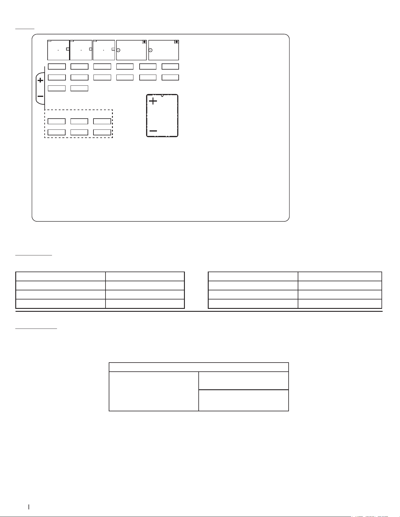
22 Section 6 — SpecificationS
Traveling Speeds
550UTV
Range gear shift lever km/h (mph)
Low 54.9 (34.1)
High 64.9 (40.3)
Reverse 20.9 (13.0)
750UTV
Range gear shift lever km/h (mph)
Low 57 (35.4)
High 80 (49.7)
Reverse 40 (24.8)
Vehicle Limitations
The Vehicle has been thoroughly tested for proper performance with implements sold or approved by manufacturer. Use with implements which are not sold or
approved and which exceed the maximum specifications listed below, or which are otherwise unfit for use on this vehicle, may result in vehicle malfunction or
failures with a possibility of vehicle damage, property damage and injury to the operator or others. Any malfunctions or failures of the vehicle resulting from use with
improper implements are not covered by the warranty.
Max cargo loading weight
Cargo Bed Capacity = 227 kg (500 lb)
Vehicle Total Load Capacity = 453.5 kg
(1000 lb)
* (Operator + one passenger + opt +
acc) weight + trailer weight
Max. rolling weight trailer
544 kg (1200 lbs)
Max. tongue weight
50 kg (110 lbs)
1. Above mentioned specifications are based on level ground condition.
Fuse Box
Spare fuse
F1 20A Fan motor fuse
F2 5A Fan control system/Pump
relay fuse
F1 20A Fan motor fuse
F2 5A Fan control system/Pump
relay fuse
F3 5A Winch controller fuse
F5 10A DC fuse
F10 10A Rear axle differential fuse
F11 10A Headlight fuse
F12 5A Meter, ECU energize fuse
F14 30A Eps motor fuse
F4 5A The four-wheel drive
differential control relay fuse
F6 10A Pump/Meter, ECU
switch fuse
F7 10A Horn/Neutral start relay
fuse
F9 5A Speed limiter/EPS controller
fuse
F13 30A Standby connection post
fuse
K1:MODEL: HFV11 12-H-R ( DG )
Fuel pump relay
K3:MODEL: HFV11 12-H-R ( DG )
Ignition switch relay
K2:MODEL: HFV11 12-H-R ( DG )
Neutral start relay
K4:MODEL: HFV9 012-1ZR
All-wheel-drive relay
K5:MODEL: HFV9 012-1ZR
Differential relay
F8 5A Signal light system/Neutral
start relay fuse
K5
K4K3K2K1
Spare fuse
20A
30A
10A
10A
5A
5A
F1 F2 F3 F4 F5 F6
F7 F8 F9 F10 F11 F12
F13 F14
OUT
Flasher
Figure 6-1

CUB CADET LLC -- LIMITED WARRANTY
100016 Rev I (January 8, 2021)
The limited warranty set forth herein is given by Cub Cadet LLC with respect to a new Cub Cadet® product (hereinafter “Product”) purchased and used in the
United States and/or Canada to the Initial Purchaser (as defined herein). This limited warranty does not cover Emission Control Systems and is not a Federal
Emission Control Warranty Statement, as defined by U.S. federal law. Please refer to the Federal Emission Control Warranty Statement in the operator’s manual
for warranties covering Emission Control Systems.
Scope of the Limited Warranty
Cub Cadet LLC warrants that the Product (except with regard to the components and circumstances defined below as “Exclusions”) will be free from defects in
materials and workmanship during the Warranty Period, as defined below. For purposes of this limited warranty, the “Initial Purchaser” is the first person/company
to purchase this new Product from an authorized Cub Cadet dealer, distributor, and/or retailer of such products, including a party for whom said Product was
purchased as a gift. This limited warranty is non-transferrable. During the Warranty Period, Cub Cadet LLC will, at its option, either repair or replace any original
part that is covered by this limited warranty and is determined to be defective in workmanship or material. “Commercial Use” shall be defined as any commercial,
professional, agricultural, institutional, or income-producing use of the Product. See notes below as to Commercial Use Warranty.
Cub Cadet® Warranty Information
Handheld Product* Warranty Period
Chainsaws, Cultivators, Blowers, Brushcutters, Trimmers 3 Year
Wheeled Chore and Snow Product*
Chipper-Shredders, Chipper-Shredder Vacuums, Blowers, Log Splitters, Snow Blowers 3 Year
Tillers, String Trimmers, Lawn Edgers, Pressure Washers CC3224, CC3425 & CC4033 3 Year†
Pressure Washers 2 Year†
Battery Powered Product
60 Volt Max Product Series, CC30E, XT1 LT42E, ZT1 42E 3 Year†
60 Volt Max Product Series, CC30E, XT1 LT42E, ZT1 42E Batteries 4 Year†
Gas Powered Product
Ultima ZTX Series 4 Year/500 hour (whichever comes first)
Z-Force SX 4 Year/500 hour (whichever comes first)
Walk-Behinds, Wide-Area Walk-Behinds, CC30 Riders, XT1 & XT2 Enduro Series, RZT S/SX, Ultima ZT Series,
Z-Force S
3 Year†
23” Walk-Behinds, XT3 Enduro Series 4 Year†
Rotary Spreader 1 Year
Gas Blowers, PRO HW, PRO X-636 2 Year
PRO Z 500/700/900, PRO X-648/654/660, TANK LZ/SZ 3 Year
PRO Z 100 S 2 Year/NHL (No Hour Limit) or 4 Year/500 hour
(whichever comes first)
Utility Vehicle*
Challenger Series, Volunteer Series 1 Year
Additional Warranty Notes
Lead-Acid Batteries: Are covered by a one (1) year prorated limited warranty against defects in material and workmanship, with 100% replacement during
the first three (3) months, from the date of original purchase by the Initial Purchaser. After three (3) months, the battery replacement credit is based on the
months remaining in the twelve (12) month period, dating back to the date of original purchase by the Initial Purchaser. Any replacement battery will be
warranted only for the remainder of the original warranty period.
Frames: The frame, chassis, and front axle on all XT1, XT2 and XT3 products are covered for “Residential Use” by a five (5) year limited warranty. The frame on
all Ultima ZT and ZTX series products are covered for “Residential Use” by a seven year Limited Lifetime Warranty.
Mowing Decks: 1) Cub Cadet LLC warrants the mowing decks under the warranty of the product it came with unless otherwise stated. 2) When so equipped,
the optional fabricated cutting deck shell (excluding wear parts, etc. thereon) shall be warranted against defects in material and workmanship for the lifetime
of the product, namely for as long as it is owned by its Initial Purchaser or the party for whom it was originally purchased as a gift, or seven (7) years from the
date of its initial sale to an Initial Purchaser, whichever comes first. 3) The deck shell, deck spindles, and deck steel pulleys (collectively the “Deck Assembly”)
on PRO Z 500 / 700 / 900 and PRO X-600 product only, shall also be warranted to be free from defects in material and workmanship for up to an additional
two (2) years (a total of five (5) years from date of purchase) or 1,750 cumulative hours of operation, whichever comes first. For purposes of clarity, no hour
limitation applies during the initial three (3) year period described above.
Snow Blowers: Three-Stage and Two-Stage (excluding 2X 24 models) - Auger gear boxes have a five (5) year limited warranty.
L and S Series: RZT L/LX, Z-Force L/LX/SZ, PRO Z 100 L, Z-Force Commercial (LZ/SZ), and Tank (L/S): Please refer to warranty included with Operator’s
Manual.
Attachments/Accessories: Please refer to warranty with Operator’s Manual.
*Limited Commercial Use Warranty: Handheld products – 90 days; Chipper-Shredder Vacuums, Blowers, Log Splitters, Snow Blowers – 1 year;
Utility Vehicle – 6 month.
† No Commercial Use Warranty: Tillers, String Trimmers, Lawn Edgers, Pressure Washers, Battery Powered Product, Walk Behind Mowers, 60 Volt Max
Product Series, CC30 Riders, Enduro Series, RZT S/SX, Ultima ZT Series, and Z-Force.
The limited warranty is non-transferrable

How to Get Service Under This Limited Warranty
In order to qualify for the limited warranty, as set forth herein, the repairs
made under this warranty must be performed by an authorized Cub Cadet
service provider. To locate a Cub Cadet service provider, contact your
authorized Cub Cadet dealer, distributor, or retailer, or contact Cub Cadet
LLC at P.O. Box 368023, Cleveland, Ohio 44136-0019, or call 1-877-282-8684,
or log on to our Website at www.cubcadet.com. For Canada, contact MTD
Products Limited, 97 Kent Ave, Kitchener, ON N2G 3R2, or call 1-800-668-1238,
or log on to our Website at www.cubcadet.ca. This limited product warranty is
provided by Cub Cadet LLC and is the only product warranty provided by Cub
Cadet LLC for the Product. A COPY OF YOUR SALES RECEIPT IS REQUIRED FOR
WARRANTY SERVICE.
What This Limited Warranty Does Not Cover
This limited warranty does not cover the following (the “Exclusions”):
1. Product purchased outside of the United States or Canada.
2. Emission Control Systems. These items are subject to a separate warranty
under the applicable Federal Emission Control Warranty Statement.
Please refer to the applicable Federal Emission Control Warranty
Statement for terms and conditions relating to Emission Control Systems.
3. Damage due to lack of maintenance and/or improper maintenance, as
described in the operator’s manual.
4. Normal wear and tear resulting from use of the Product.
5. Normal Wear Parts (as defined herein) are warranted to be free from
defects in material and workmanship for a period of thirty (30) days from
the date of original purchase by the Initial Purchaser for residential use,
and for 30 days or 100 hours (whichever occurs first) for Product used
commercially. Depending on Product, Normal Wear Parts include, but
are not limited to items such as: belts, blades, blade adapters, grass bags,
rider deck wheels, seats, shave plates, skid shoes, tines, filters, nozzles,
hoses, O-rings, spray guns, wands, tires, spark plugs, fuses, bump knobs,
outer spools, cutting line, inner belts, starter pulley, starter rope, drive
belts, saw chains, guide bars, and other consumable items.
6. Log splitter pumps, valves, and cylinders are covered for a period of one
(1) year.
7. Use of the product that is not consistent with the intended use thereof,
as described in the operating instructions, including, but not limited
to, abuse, misuse and/or neglect of the Product, or any use inconsistent
with and/or non-compliant with instructions contained in the Operator’s
Manual. This includes operation in sandy and/or corrosive environments.
8. Any Product that has been altered or modified in a manner not
consistent with the original design of the Product or in a manner not
approved by Cub Cadet LLC.
9. Paint repairs or replacements for defective paint (including materials and
application) are covered for a period of three (3) months.
10. Wheel rims (when so equipped) are covered for a period of three (3)
months for manufacturing defects.
This warranty does not cover, and Cub Cadet LLC disclaims any
responsibility for, matters including, but not limited to, the following:
1. Loss of time or loss of use of the Product.
2. Transportation costs and other expenses incurred in connection with the
transport of the Product to and from the authorized Cub Cadet service
provider.
3. Any loss or damage to other equipment or personal items.
4. Damages caused by improper maintenance or the use of other than the
specified fuel, oil, or lubricants, as approved in the operator’s manual.
5. Damage resulting from the installation or use of any accessory or part
not approved by Cub Cadet LLC for use with the Product.
Limitations
1. THERE ARE NO IMPLIED WARRANTIES, INCLUDING, BUT NOT LIMITED
TO, ANY IMPLIED WARRANTY OF MERCHANTABILITY OR FITNESS FOR
A PARTICULAR PURPOSE. NO WARRANTY SHALL APPLY AFTER THE
APPLICABLE WARRANTY PERIOD, AS SET FORTH ABOVE, AS TO THE
PARTS AS IDENTIFIED. NO OTHER EXPRESS WARRANTY OR GUARANTY,
WHETHER WRITTEN OR ORAL, EXCEPT AS MENTIONED ABOVE, GIVEN
BY ANY PERSON OR ENTITY, INCLUDING A DEALER OR RETAILER, WITH
RESPECT TO ANY, PRODUCT SHALL BIND CUB CADET LLC. DURING
THE WARRANTY PERIOD, THE EXCLUSIVE REMEDY IS REPAIR OR
REPLACEMENT OF THE DEFECTIVE PART, AS SET FORTH ABOVE. (SOME
STATES DO NOT ALLOW LIMITATIONS ON HOW LONG AN IMPLIED
WARRANTY LASTS, SO THE ABOVE LIMITATION MAY NOT APPLY TO YOU.)
2. THE PROVISIONS, AS SET FORTH HEREIN, PROVIDE THE SOLE AND
EXCLUSIVE REMEDY ARISING FROM THE SALE. CUB CADET LLC SHALL
NOT BE LIABLE FOR INCIDENTAL OR CONSEQUENTIAL LOSS OR DAMAGES
INCLUDING, WITHOUT LIMITATION, FOR TRANSPORTATION OR FOR
RELATED EXPENSES, OR FOR RENTAL EXPENSES TO TEMPORARILY
REPLACE A WARRANTED PRODUCT. (SOME STATES DO NOT ALLOW
THE EXCLUSION OR LIMITATION OF INCIDENTAL OR CONSEQUENTIAL
DAMAGES, SO THE ABOVE EXCLUSION OR LIMITATION MAY NOT APPLY
TO YOU.)
3. IN NO EVENT SHALL RECOVERY OF ANY KIND BE GREATER THAN THE
AMOUNT OF THE PURCHASE PRICE OF THE PRODUCT SOLD. ALTERATION
OF THE SAFETY FEATURES OF THE PRODUCT SHALL VOID THIS LIMITED
WARRANTY. YOU ASSUME THE RISK AND LIABILITY FOR LOSS, DAMAGE,
OR INJURY TO YOU AND YOUR PROPERTY, AND/OR TO OTHERS AND
THEIR PROPERTY, ARISING OUT OF THE USE OR MISUSE OR INABILITY TO
USE THE PRODUCT.
4. This limited warranty extends to the Initial Purchaser only and, except
as otherwise stated herein, the applicable Warranty Period will begin
on the original date of purchase of the Product. In the event that the
original date of purchase of the Product is indeterminable, then the
Warranty Period shall be established as beginning on the Product’s date
of manufacture, as determined by Cub Cadet LLC, and ending six (6)
months after the applicable Product Warranty Period, as defined above.
In no event shall a Product’s warranty extend beyond the applicable
Warranty Period.
How State Law Relates to This Warranty
This limited warranty gives you specific legal rights, and you may also have
other rights, which vary from state to state.
100016 Rev I (January 8, 2021)
