
INSTRUCTION MANUAL
CC-INARTS
CC-SURF2S
CC-PARA4S
CC-PARA4W
CC-PARA3S
CC-PARA3W
CC-PARA2S
CC-PARA2W
CEILING CASSETTE RANGEHOODS
(06.2018 / V11)
Installation / Operation / Maintenance

Page 2
WELCOME
Thank you for purchasing this Schweigen IN
appliance.
To achieve the optimal performance from your
appliance, and to avoid the risk of accident or
damage, it is essential to read this manual before
installation and rst time use.
This guide contains important information on the
use and maintenance of the appliance, as well as
important safety notes.
Your appliance has been thoroughly checked for
safety and functionality before being packaged
and leaving the manufacturer.
Please keep this instruction manual in a safe
place so you can refer to it at any time.
IMPORTANT!
The appliance should only be
operated when you have read and
understood this manual thoroughly.
The appliance can be only used for the
purpose for which it was designed.
Any other use is improper and can be
dangerous.
Installation and maintenance of
electrical appliances must only
be carried out by qualied and
authorised professionals familiar
with Australian Appliance Industry
regulations.
Upon collection or delivery of your
appliance, any damage or defects
must be reported within 48 hours
to your retailer or Schweigen
Customer Service, in order
to recognise any claim.
The manufacturer reserves the right
to introduce product improvements,
which do not aect the operation of
the appliance.

Page 3
INDEX
Important safety information ................................................................................................................ 4
Description ................................................................................................................................................ 7
Installation ................................................................................................................................................9
Operation ................................................................................................................................................19
Cleaning and maintenance ...................................................................................................................21
Troubleshooting .....................................................................................................................................25
Technical Specications .......................................................................................................................28
Disclaimer ................................................................................................................................................31

Page 4
IMPORTANT SAFETY INFORMATION
Please read the instructions carefully.
Only then will you be able to operate your
appliance safely and correctly. Retain the
instruction manual for future use or for
subsequent owners.
Check the appliance for damage after
unpacking it. Do not connect or install
the appliance if it has been damaged in
transport.
Any damage must be reported within
48 hours.
There must be adequate ventilation in the
room when the rangehood is used at the
same time as appliances burning gas or
other fuels.
The air must not be discharged into a ue
that is used for exhausting fumes from
appliances burning gas or other fuels.
Air exhaust systems must be installed in
accordance with local and federal laws.
There is a re risk if regular cleaning is
not carried out in conjunction with the
instructions.
Do not ambé (ignite food while cooking)
under the rangehood. This will damage the
rangehood and will void warranty.
Do not ignite burners that give o
intense uncontrolled ames beneath the
rangehood.
Flames beneath the pan must be
contained at all times and cannot exceed
the width of the pan in use.
Do not leave any packaging material (bags,
corner brackets etc.) within reach of
children.
This appliance is not intended for use by
person/s (including children) with reduced
physical, sensory or mental capabilities,
or lack of experience and/or knowledge.
Unless, the person is given supervision or
instruction concerning the safe usage of
the appliance by person/s responsible for
their safety. Children must be supervised
to ensure that they do not play with the
appliance, it is not a toy.
Accessible parts may become hot when
used with cooking appliances.
Before performing any cleaning or
maintenance, disconnect the rangehood
from the mains power, using the
respective mains or sector switch, or by
unplugging it.
Do not use the rangehood without the
grease lters.
Keep the grease lters clean and respect
the recommended cleaning frequencies.
It is forbidden to use the rangehood as an
aspirator.

IMPORTANT SAFETY INFORMATION
Page 5
BEFORE INSTALLATION
We recommend this appliance be installed
or repaired by a qualied Schweigen Home
Appliances technician.
Please see our website www.
schweigen.com.au for a list of our
recommended installers.
It is dangerous to modify any part of this
appliance. Modication of any kind will
immediately void the warranty.
The manufacturer declines all
responsibility in case of failure to adopt
proper safety measures.
Ensure that the location in which this
appliance is installed, has good and
permanent ventilation.
Please consult local laws and regulations
and install in accordance.
Please use an earthed electrical connector
that coincides with relevant local laws and
regulations.
Check that the power voltage in your area
corresponds to the appliance voltage
indicated on the rating label.
This appliance must be connected to an
electrical supply that has a grounded
connection.
Check that the indicated instructions and
local regulations are met and carried out
by a qualied technician, using materials
that are complaint with the applicable
legislation.
Schweigen will not be responsible for any
installations executed by non-qualied
technicians that fail to heed the applicable
legislation on electrical safety.
The electrical technical data can be found
inside the rangehood, after removing the
grease lters.
The exible power cables supplied are
already connected internally and emerges
from the rangehood near the air outlet
tube.
Before installing the electrical
connections, you should:
• Verify that the indicated electrical data
coincides with the voltage values and
frequency of the electrical circuit in the
house where the rangehood is to be
installed.
• Check that the premises has electrical
protection against short circuits and
electrocution.
• Before commencing maintenance
the current must be turned o using
the double-pole switch (mains power
switch). The power can only be turned
on for normal use, once the operation
has been completed.
• Ensure the supply cord is not exposed
to heat, chemicals or sharp objects. If
the supply cord is damaged, it must be
replaced by the manufacturer, service
agent or a similarly qualied person in
order to avoid a hazard.

IMPORTANT SAFETY INFORMATION
Page 6
PRODUCT USE
The Rangehood has one mode of
operation:
Air extraction: The air is drawn in by
the rangehood, ltered through the
grease lters, and expelled into the
atmosphere. Please check the cleaning
and maintenance section for advice on
the lter’s cleaning schedule.
This product is designed for household
use and must not be used for commercial
applications.
After use, always ensure that all controls
are in the “OFF” position.
Never ambé any food beneath the
rangehood.
Always switch o the power source and
unplug the connection before conducting
maintenance or cleaning.
Respect the cleaning frequencies
and intervals for changing the lters,
otherwise, the accumulated grease could
cause a re or damage to the appliance.
Changes made to the steel surface will
render the warranty invalid.
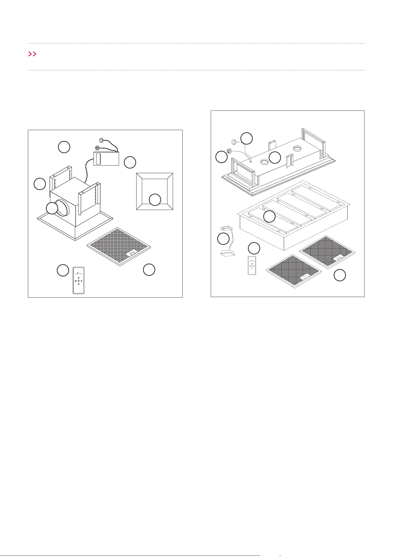
Page 7
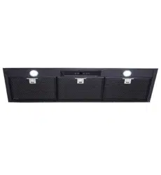
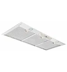
1. Connect the female plug to the Isodrive motor
system
2. Male Plug (Main Power 240V)
3. 200mm Outlet/s
4. Remote
5. Filter
6. Cover Panel with LED lights built-in
7. Control Module, supplied with main unit only
NOTE: Filter and light quantity may vary from
model to model.
*IMPORTANT: The electronics MUST be accessible
for servicing once installed, failure to do so, will
result in any charges involved with accessing the
part (removal of cabinetry etc.) being forwarded to
the customer.
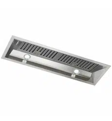
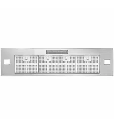
1. Connect the female plug to the Isodrive motor
system
2. Male Plug (Main Power 240V)
3. 200mm Outlet/s
4. P.A. Filter Cover Panel
5. Lamp
6. Remote
7. Filter
NOTE: Filter and light quantity may vary from
model to model.
*IMPORTANT: The electronics MUST be accessible
for servicing once installed, failure to do so, will
result in any charges involved with accessing the
part (removal of cabinetry etc.) being forwarded to
the customer.
DESCRIPTION
1 2 3 4
1 2 3 4
1
1
2
2
3
3
4
4
5
5
6
6
7
7
CC-PARA4S, CC-PARA4W, CC-PARA3S,
CC-PARA3W, CC-PARA2S and
CC-PARA2W
CC-INARTS and CC-SURF2S
Page 8
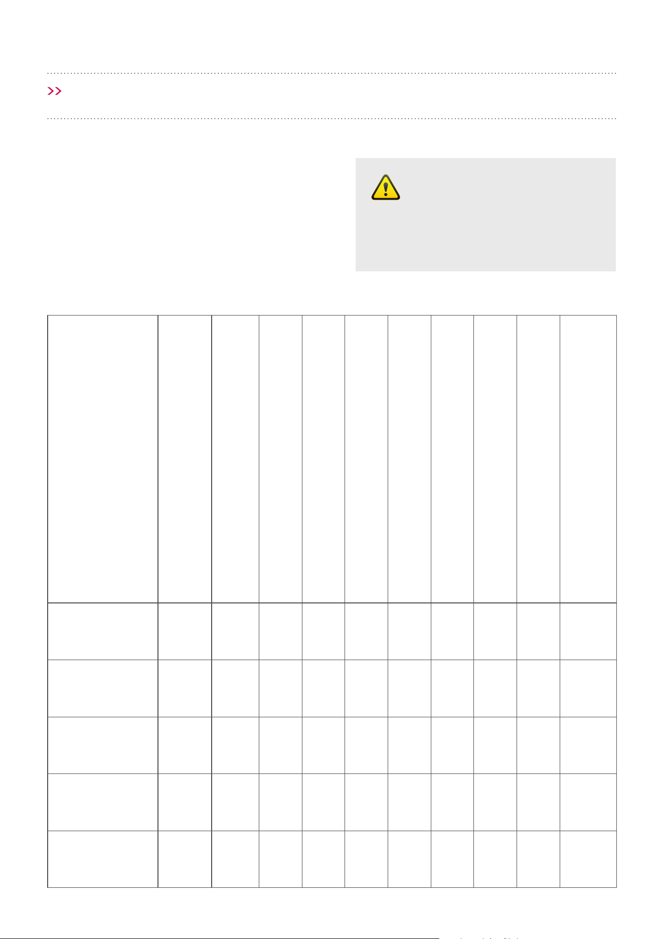
MOUNTING LAWS AND REGULATIONS
Minimum and maximum heights (cooktop-to-canopy) are legally required. This rangehood is intended for
indoor kitchen use.
Type of Cooktop Min. Height Optimal Recommended Max. Height*
Electric 1200mm 1500mm 1 x Isodrive
©
1600: 1800mm;
2 x Isodrive
©
1600: 1800mm to 2300mm;
1 x Isodrive
©
3200: 1800mm to 2100mm;
Gas 1200mm 1500mm 1 x Isodrive
©
1600: 1800mm;
2 x Isodrive
©
1600: 1800mm to 2300mm;
1 x Isodrive
©
3200: 1800mm to 2100mm;
* Installation height exceeding the recommended maximum height above the cooktop will reduce the
eectiveness of the air extraction rate.
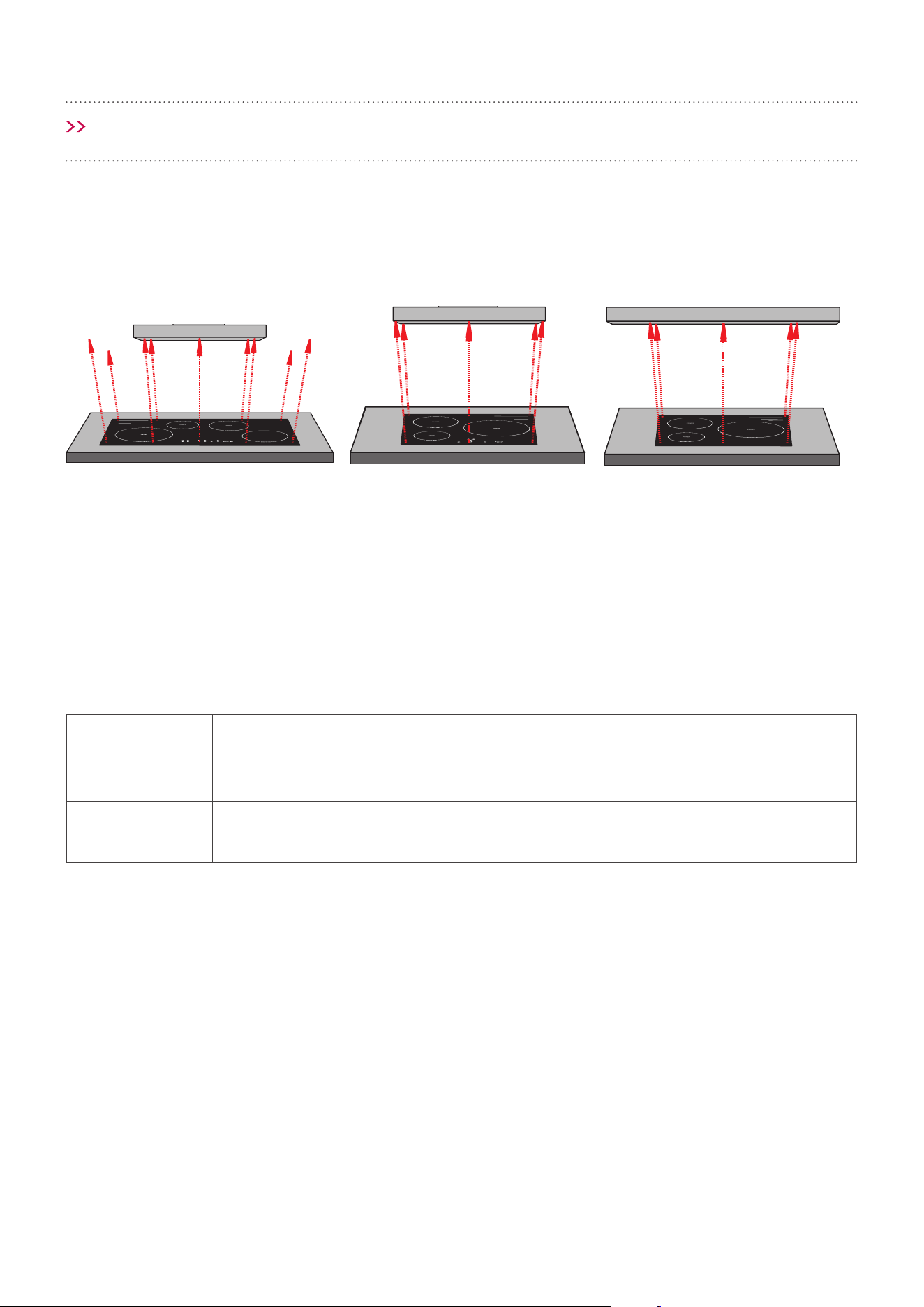
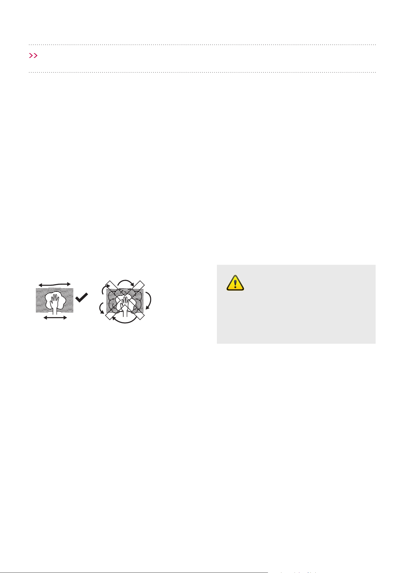
INSTALLATION
Rangehood smaller than
cooking zone
INADEQUATE
Rangehood same size as
cooking zone
ADEQUATE
Rangehood larger than
cooking zone
OPTIMAL
In addition to the size of the rangehood, the height of the rangehood above the cooktop is important.
MATCH THE RANGEHOOD SIZE TO YOUR COOKTOP
It is important to make sure the rangehood is the correct size, the larger the surface area of your rangehood the
better extraction results, see diagram below.
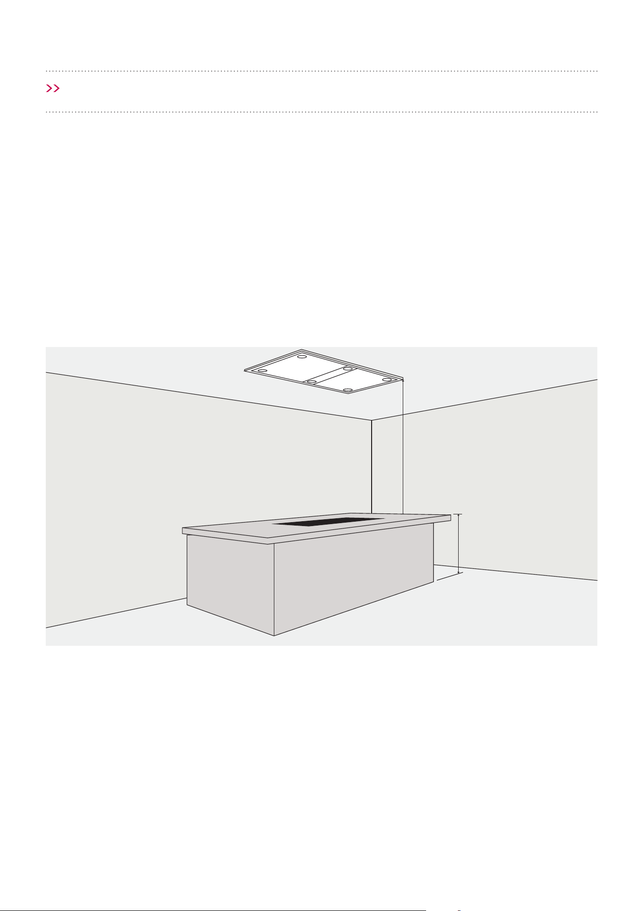
Page 9
• The location of the installation must have
permanent openings for ventilation.
• Regulations concerning the expelling
of air must be fullled.
• Please check all State and Federal Laws in
relation to the minimum and maximum heights,
concerning the expelling of air and install your
rangehood in accordance.
• It is STRONGLY RECOMMENDED that the
rangehood be installed centrally over the cooktop,
this will greatly improve its performance.
MIN 1200mm
Optimal 1500mm
MAX 1800mm
900mm
INSTALLATION
Page 10
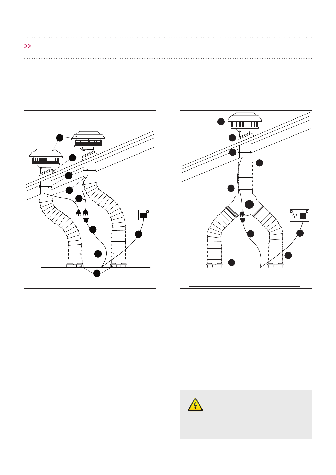
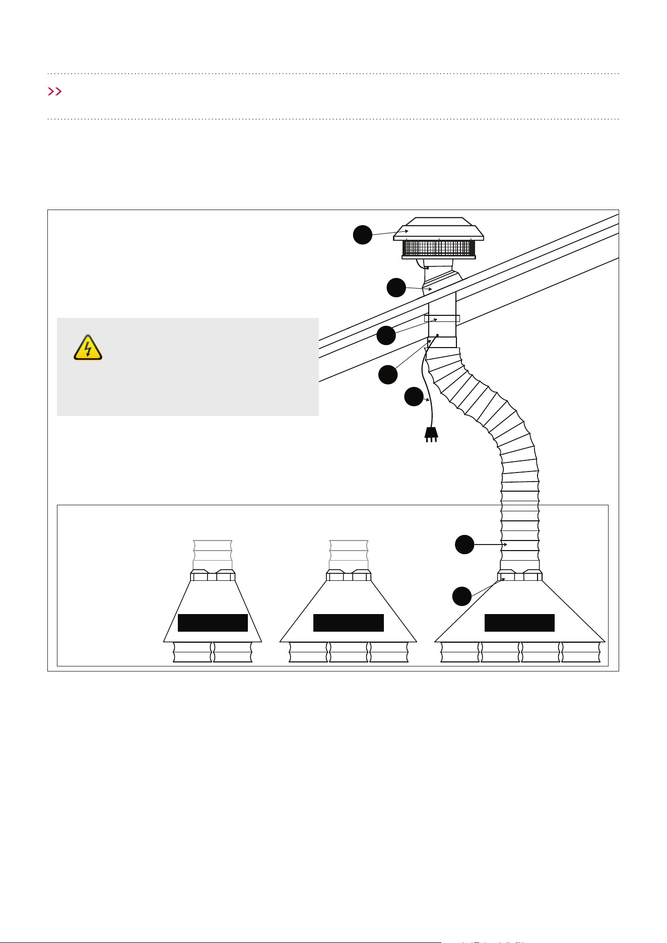
INSTALLATION
Danger
All electrical wiring from the
motor to the rangehood should
be kept inside the roof space.
SYSTEM OVERVIEW GUIDE FOR CC-SURF2S AND CC-INARTS
1. Isodrive Motor/s
2. Roof Seal Kit (Dektite)*
3. Support Straps*
4. Attach Flexi Duct to Bell-Mouth Adaptor using
cable tie or ring clamp. Please DO NOT rip the
ducting.
5. Isodrive Motor Power Lead (Male Plug)
6. Rangehood to Isodrive Motor Lead
(Female Plug)
7. Mains Power Lead (Male Plug, 10 Amp)
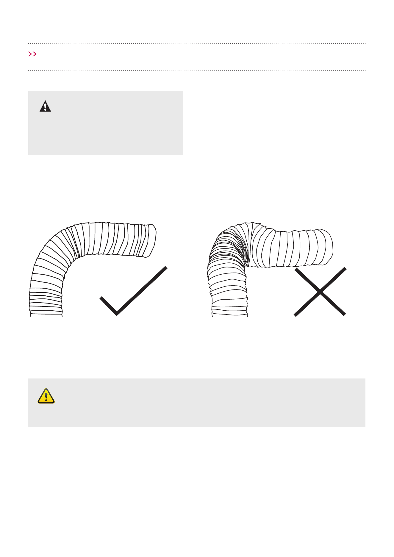
8. Flexi Ducting must be pulled taut.
DO NOT crush or kink the ducting.
Pictures are for illustrative purposes only, not to scale.
Refer A
2
3
4
5
6
7
8
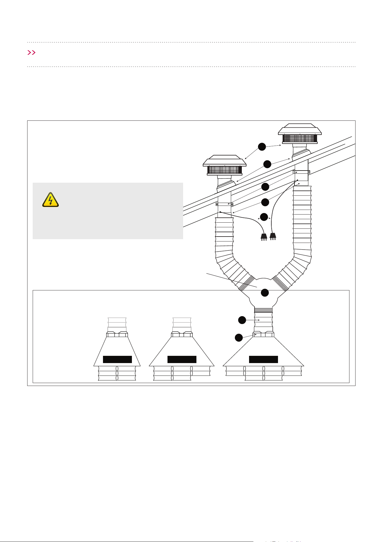
9
1
Single motor installation
1
2
3
4
5
6
10
7
8
9
9. Connect exi ducting to the outlet on
rangehood using cable tie or ring clamp.
Please DO NOT rip the ducting.
10. Y -joint
*NOTE: The Isodrive motor system does not
include the roof seal kit, cable tie, ring clamp
or the support straps.
NOTE: Please see Isodrive installation guide for
motor installation information.
Twin motor installation
Page 11
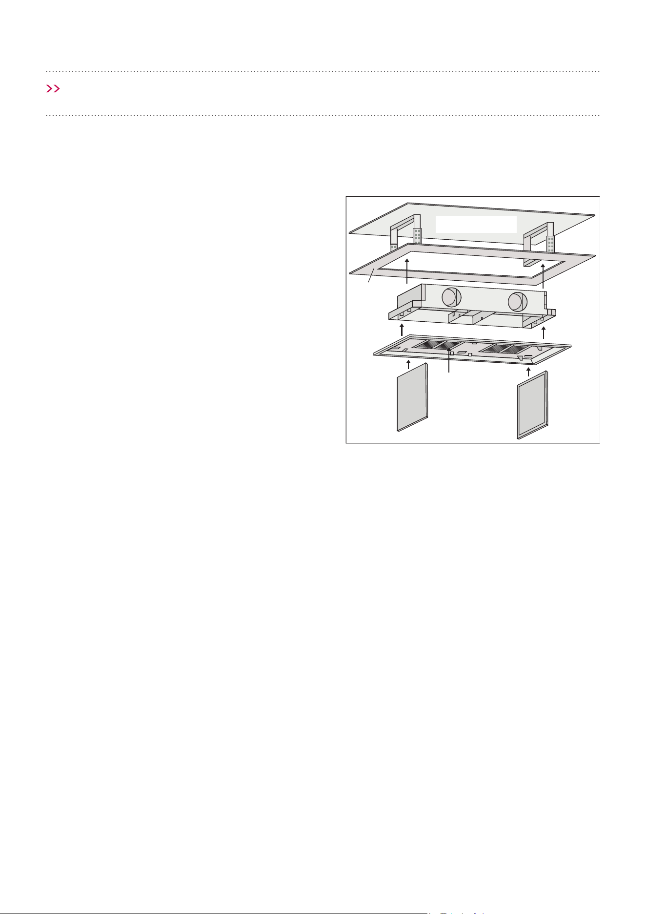
INSTALLATION
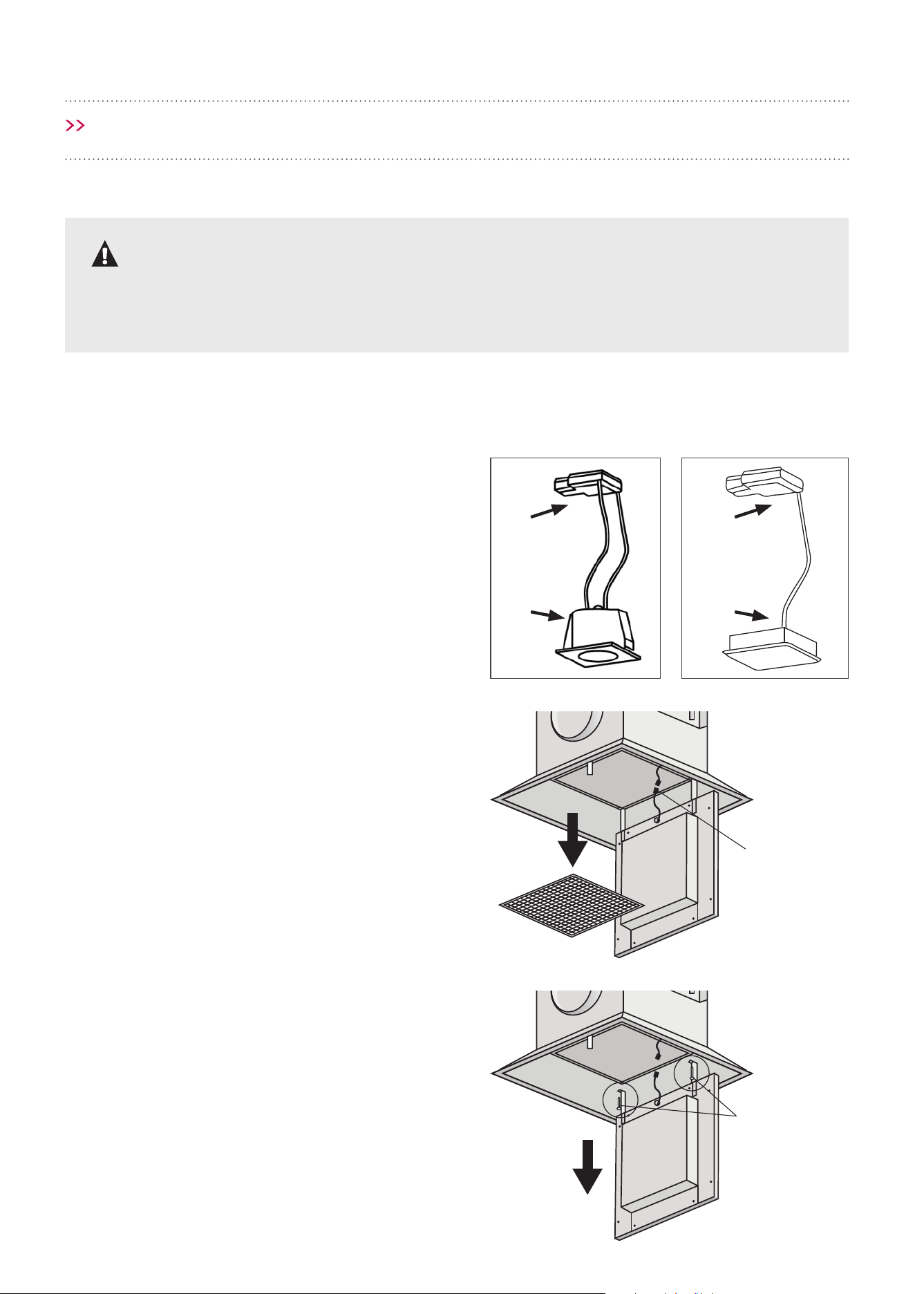
INSTALLATION GUIDE FOR CC-INARTS
AND CC-SURF2S
NOTE: We recommend using washable paint for
the ceiling where the rangehood is installed.
1. Before installing the rangehood, carefully
open the doors (D), then remove the lters (E).
Release power connection from the lighting
incorporated in the holder, then remove (C) the
fascia.
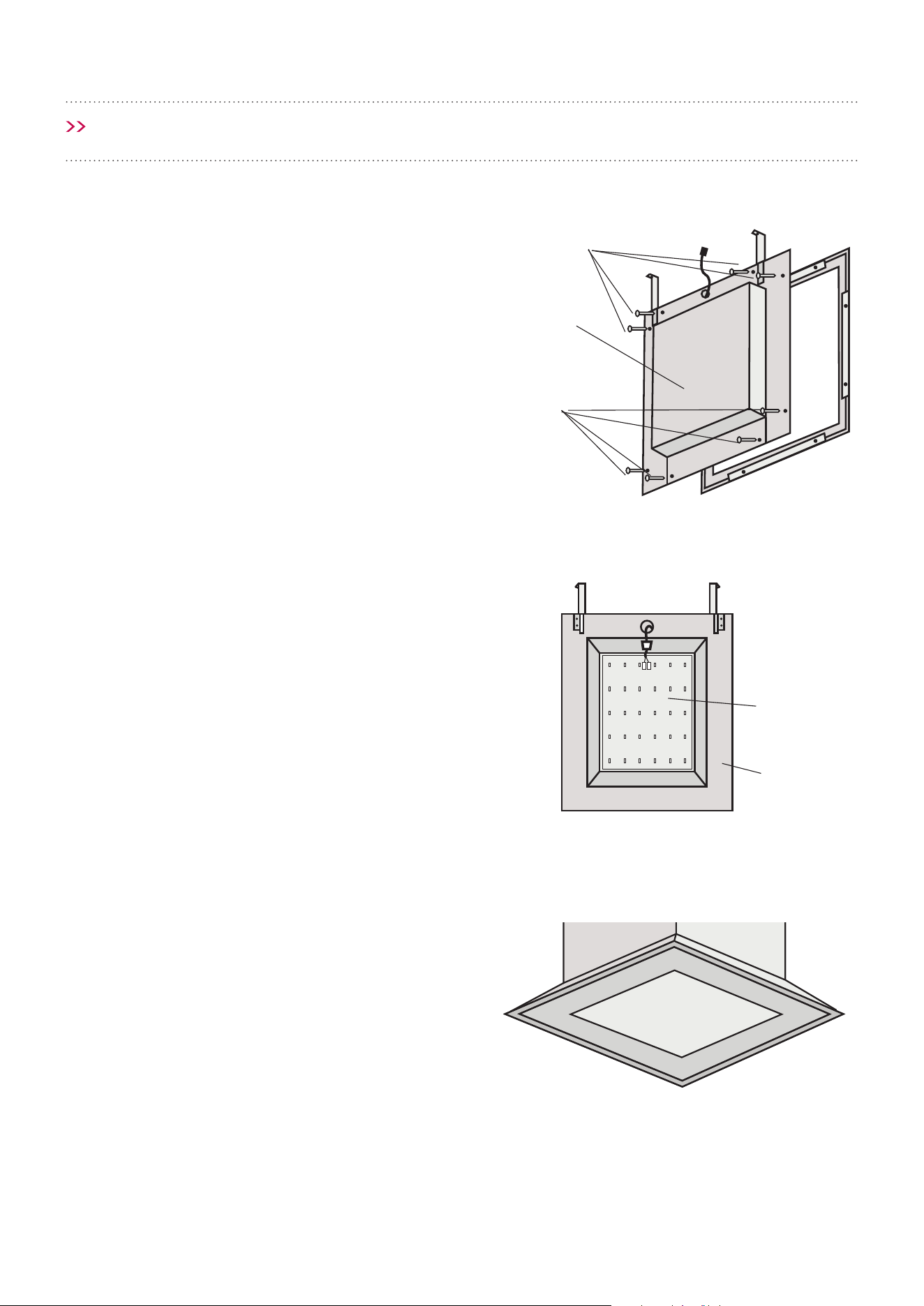
2. On the ceiling, mark the outline of the
rangehood cut out, refer to gure 1 and 2 (next
page) for dimensions.
NOTE: It is always best to use the rangehood as
a cutting guide, not the cabinet cut out diagram
as this is only a guide.
3. Fit adjustable brackets (A1) to a solid structure
and adjust the (A1) brackets to the correct
height.
4. Fit the body of the rangehood (B) to the
adjustable brackets (A1).
5. Fix fascia (C) to the body hood (B) using the
screws supplied reconnect power connection
from the lighting incorporated in the holder.
6. Fix doors or glass doors (D) to the holder hinges
(C) using the screws supplied.
7. Close doors or glass doors (D) to x the holder
magnets.
A1 A1
B
C
D
E
Overview
Solid Structure
Ceiling or
Bulkhead
Page 12
125
105.1
MAX – 450
75
655
800
750
450
950
570
415
1300
1250 cutout
31.6
Min – 260
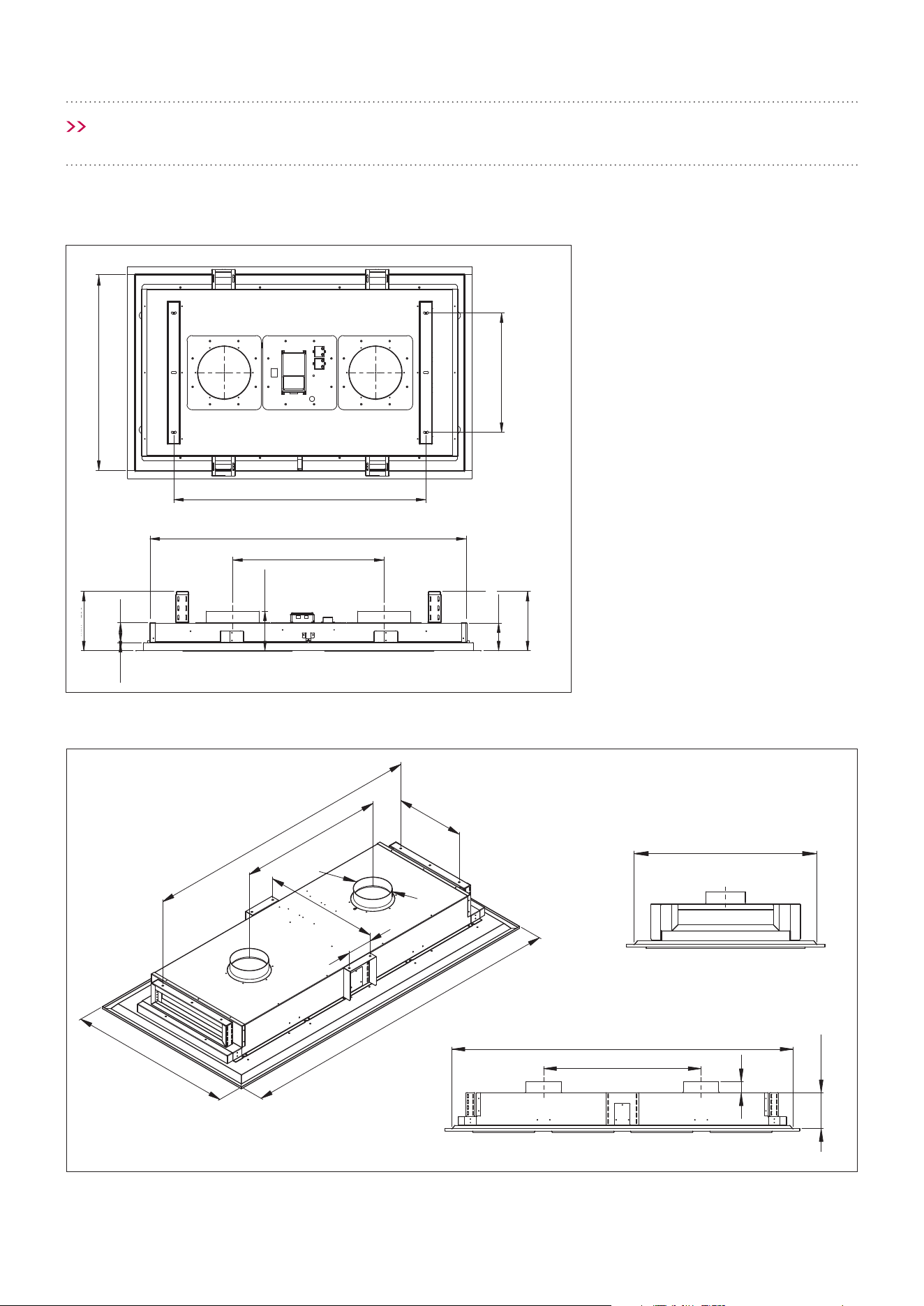
INSTALLATION
Figure 1 Cut out dimensions for CC-SURF2S
Figure 2 Cut out dimensions for CC-INARTS
Measurements in mm.
Measurements in mm.
NOTE: It is always best to use the actual rangehood ordered as a cutting guide, not the cabinet cut out diagram
as this is only a guide.
1710
2000
885
420
ø200
700
1000
Cutout: 950
Cutout: 1950
885
64
Min 210 - Max 335
150
125
105.1
MAX – 450
75
655
800
750
450
950
570
415
1300
1250 cutout
31.6
Min – 260
750
Cutout 1250
950
570
±125
7531.6
Min - 260
Max - 450
105.1
450
Page 13
INSTALLATION
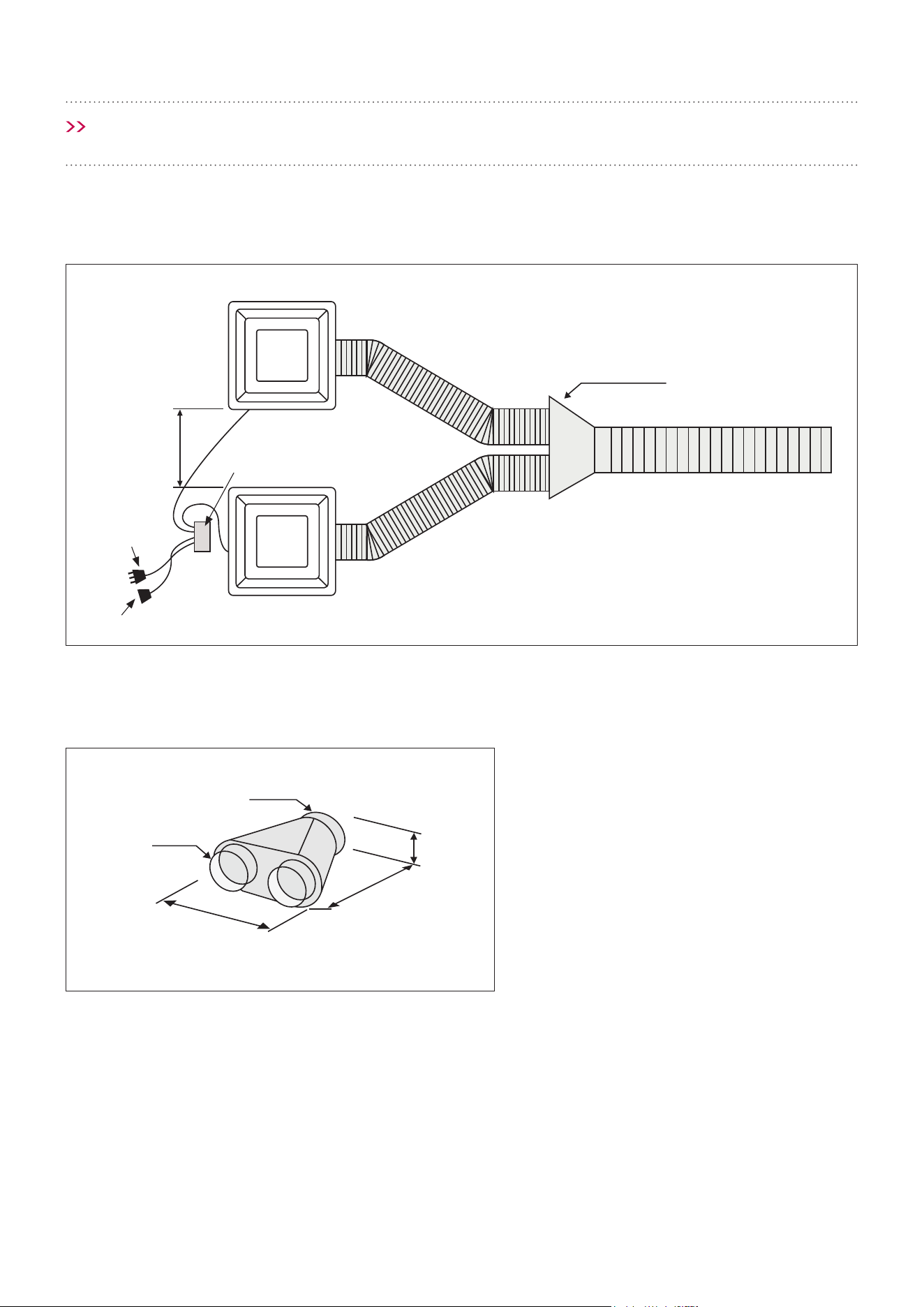
MOTOR SYSTEM OVERVIEW GUIDE FOR CC-PARA4S, CC-PARA4W, CC-PARA3S,
CC-PARA3W, CC-PARA2S, CC-PARA2W
1. Isodrive Motor/s
2. Roof Seal Kit (Dektite)*
3. Support Straps*
4. Attach Flexi Duct to Bell-Mouth Adaptor using
cable tie or ring clamp. Please DO NOT rip the
ducting.
5. Isodrive Motor Power Lead (Male Plug)
6. Flexi Ducting must be pulled taut.
DO NOT crush or kink the ducting.
Pictures are for illustrative purposes only, not to scale.
2
3
4
5
6
7
1
2-Way Adaptor 3-Way Adaptor 4-Way Adaptor
7. Connect exi ducting to the outlet on
rangehood using cable tie or ring clamp.
Please DO NOT rip the ducting.
*NOTE: The Isodrive motor system does not
include the roof seal kit, cable tie, ring clamp
or the support straps.
NOTE: Please see Isodrive installation guide for
motor installation information.
Single motor installation
Danger
All electrical wiring from the
motor to the rangehood should
be kept inside the roof space.
Connecting to 2, 3 or 4-Way Adaptor
Page 14
INSTALLATION
MOTOR SYSTEM OVERVIEW GUIDE FOR CC-PARA4S, CC-PARA4W, CC-PARA3S, CC-
PARA3W, CC-PARA2S, CC-PARA2W
1. Isodrive Motor/s
2. Roof Seal Kit (Dektite)*
3. Support Straps*
4. Attach Flexi Duct to Bell-Mouth Adaptor using
cable tie or ring clamp. Please DO NOT rip the
ducting.
5. Isodrive Motor Power Lead (Male Plug)
6. Y -joint
7. Flexi Ducting must be pulled taut.
DO NOT crush or kink the ducting.
Pictures are for illustrative purposes only, not to scale.
2
3
4
5
7
6
8
1
2-Way Adaptor 3-Way Adaptor 4-Way Adaptor
8. Connect exi ducting to the outlet on
rangehood using cable tie or ring clamp.
Please DO NOT rip the ducting.
*NOTE: The Isodrive motor system does not
include the roof seal kit, cable tie, ring clamp
or the support straps.
NOTE: Please see Isodrive installation guide for
motor installation information.
Twin motor installation
Danger
All electrical wiring from the
motor to the rangehood should
be kept inside the roof space.
Connecting to 2, 3 or 4-Way Adaptor
Y joint 200 x 200 x 200
Page 15
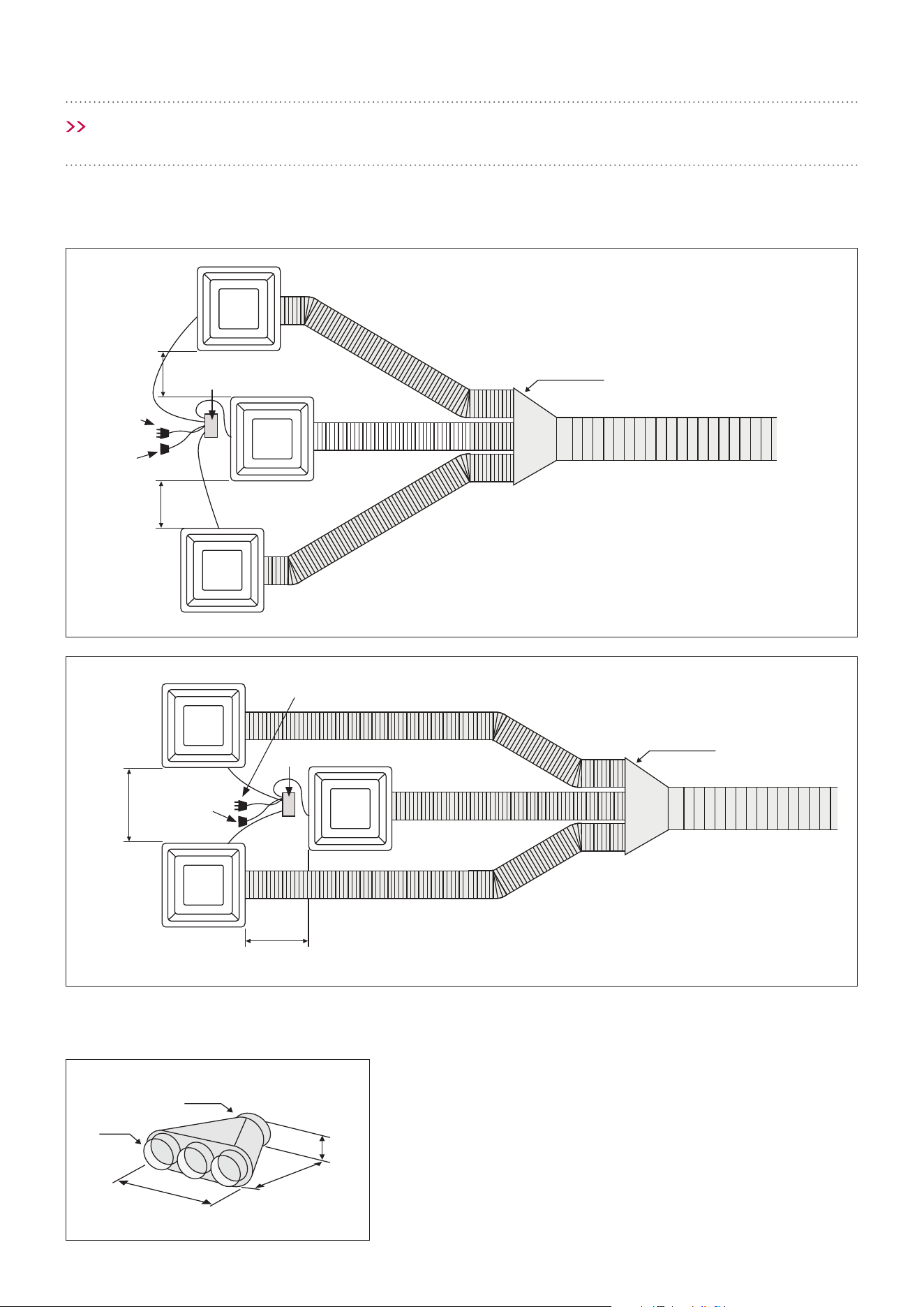
INSTALLATION
EXAMPLE INSTALLATION FOR TRIPLE MODULES
Sub
Main
Sub
3-Way Adaptor
Min 300
Max 1000
Control Module
Control Module
Mains Plug
Mains Plug
Motor Power Lead
Motor
Power Lead
Min 300
Max 1000
Main
Sub
Sub
3-Way Adaptor
Min 300
Max 1000
Min 300
Max 1000
200
120
500
420
205
3-WAY ADAPTOR
Measurements in mm.
Measurements in mm.
Measurements in mm.
NOTE: Please take note to the minimum and
maximum spacing between each module. This is
important as it will aect the performance should
they be installed outside these parameters.
NOTE: Please take note to the minimum
and maximum spacing between each
module. This is important as it will aect
the performance should they be installed
outside these parameters.
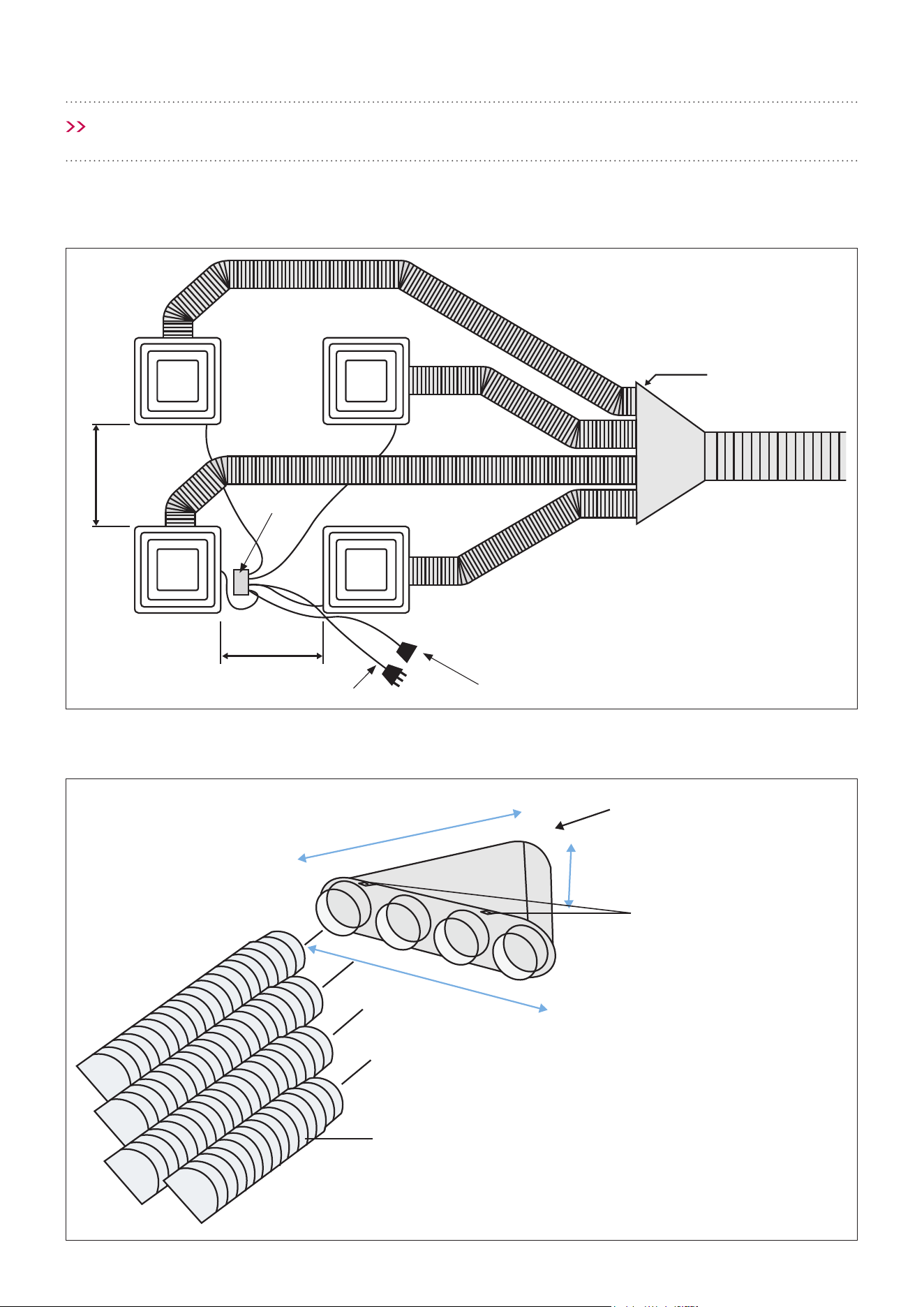
Page 16
INSTALLATION
4-Way Adaptor
Connect to 200mm
flexi ducting
Mounting points
Ducting
550
700
205
Example Installation for Multiple Modules
Sub Sub
Sub
Main
4-Way Adaptor
Control Module
Mains Plug
Motor Power Lead
Min 300 - Max 1000
Min 300 - Max 1000
Measurements in mm.
Measurements in mm.
NOTE: Please take note to the minimum and
maximum spacing between each module. This is
important as it will aect the performance should
they be installed outside these parameters.
Page 17
INSTALLATION
Sub
2-Way Adaptor
Main
Min 300
Max 1000
EXAMPLE INSTALLATION FOR TWIN MODULES
2-WAY ADAPTOR
Measurements in mm.
Measurements in mm.
155
315
325
120/150
150/200
NOTE: Please take note to the minimum and
maximum spacing between each module. This is
important as it will aect the performance should
they be installed outside these parameters.
Control Module
Mains Plug
Motor Power Lead
Page 18
INSTALLATION
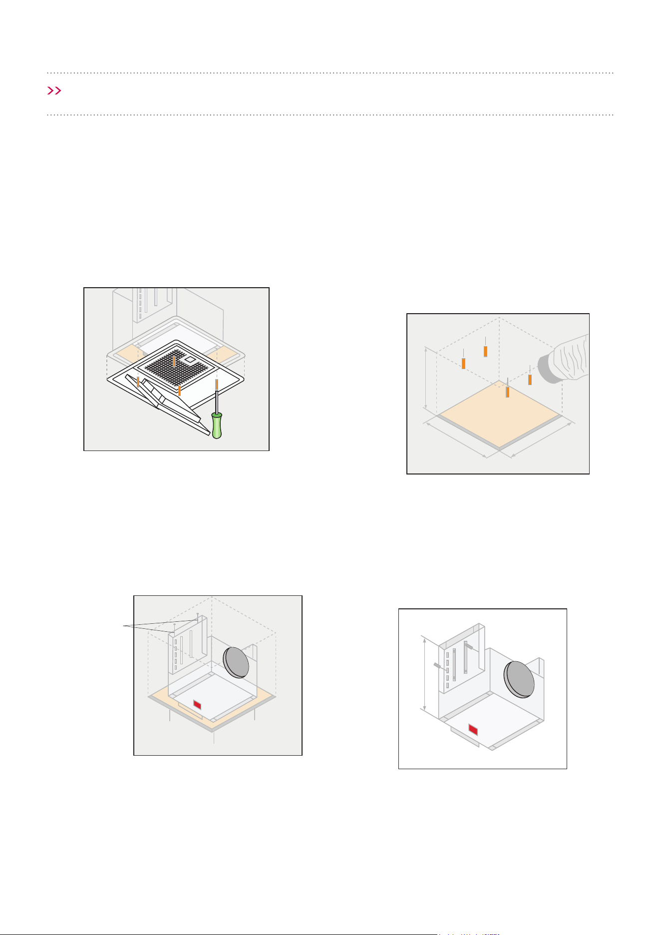
INSTALLATION GUIDE FOR CC-PARA4S, CC-PARA4W, CC-PARA3S, CC-PARA3W,
CC-PARA2S, CC-PARA2W MODULES
NOTE: We recommend using washable paint for the ceiling where the rangehood is installed.
Figure A
Figure B
Figure C
340mm
340mm
90mm
Step 1
Remove the ange and lid before installation.
Step 3
Mark and place the 4 xing points (Figure B).
Step 4
Regulate the mounting brackets (Figure C) to the
desired measurements.
Step 2
On the ceiling, draw the outline of the hole required
to house the extractor hood, see gure A for cutout
dimensions.
Fixing points
Page 19
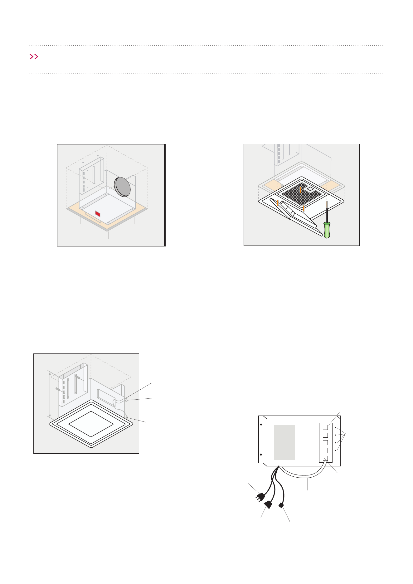
INSTALLATION
Step 5
Place the modular into the opening of ceiling,
connect the ducting. When ducting is xed to the
modular, secure it with the xing (Figure D).
Step 6
To connect the electrical cable of the lid to the
connections box and x the lid with the screws, it
must remain joined to the body (Figure E).
Step 7
Close the lid until it remains xed with the magnets
(Figure F).
Step 8 Control Module
Connect each power plug to the control module.
Then connect mains power cable and motor cables.
Each module connects to one of the four
connectors on (A), it does not matter which order
they are connected.
Connect each earth lead from each light module to
the earth connectors.
Figure D Figure E
Figure F
Mains Power Lead
Motor Power
Lead
White Power Lead,
connects to position 1.
Position 1
Earth
connectors
A
Power plug
Earth
connector
To main isolation
switch
The main unit will have
a isloation switch lead,
plug it into control
module
Page 20
INSTALLATION
Figure F Cut out dimensions for CC-PARA4S, CC-PARA4W, CC-PARA3S, CC-PARA3W, CC-PARA2S and
CC-PARA2W
265
130
ø120
ø120
360 360
Cutout 340 x 340
310
220
135
Measurements in mm.
Page 21
INSTALLATION
ISODRIVE MOTOR SETUP
NOTE
Please refer to the Isodrive motor installation guide for more details on
exi ducting installation and Isodrive motor installation.
FLEXIBLE DUCTING INSTALLATION
Please do not crush or kink exi ducting, as it will reduce air ow and may cause noise to occur through the
system. Ducting needs to be kept taut at all times.
For technical support, please contact 1300 829 066.
IMPORTANT
Please ensure all plastic
protection on the rangehood and
lters are removed before use.
Page 22
OPERATION
REMOTE CONTROL USAGE
Starting the rangehood for the rst time using the
remote control:
Put the safety switch ON (this switch is inside the
main rangehood). Wait about 5 seconds for the
circuit to test the memory.
1 2 3 4
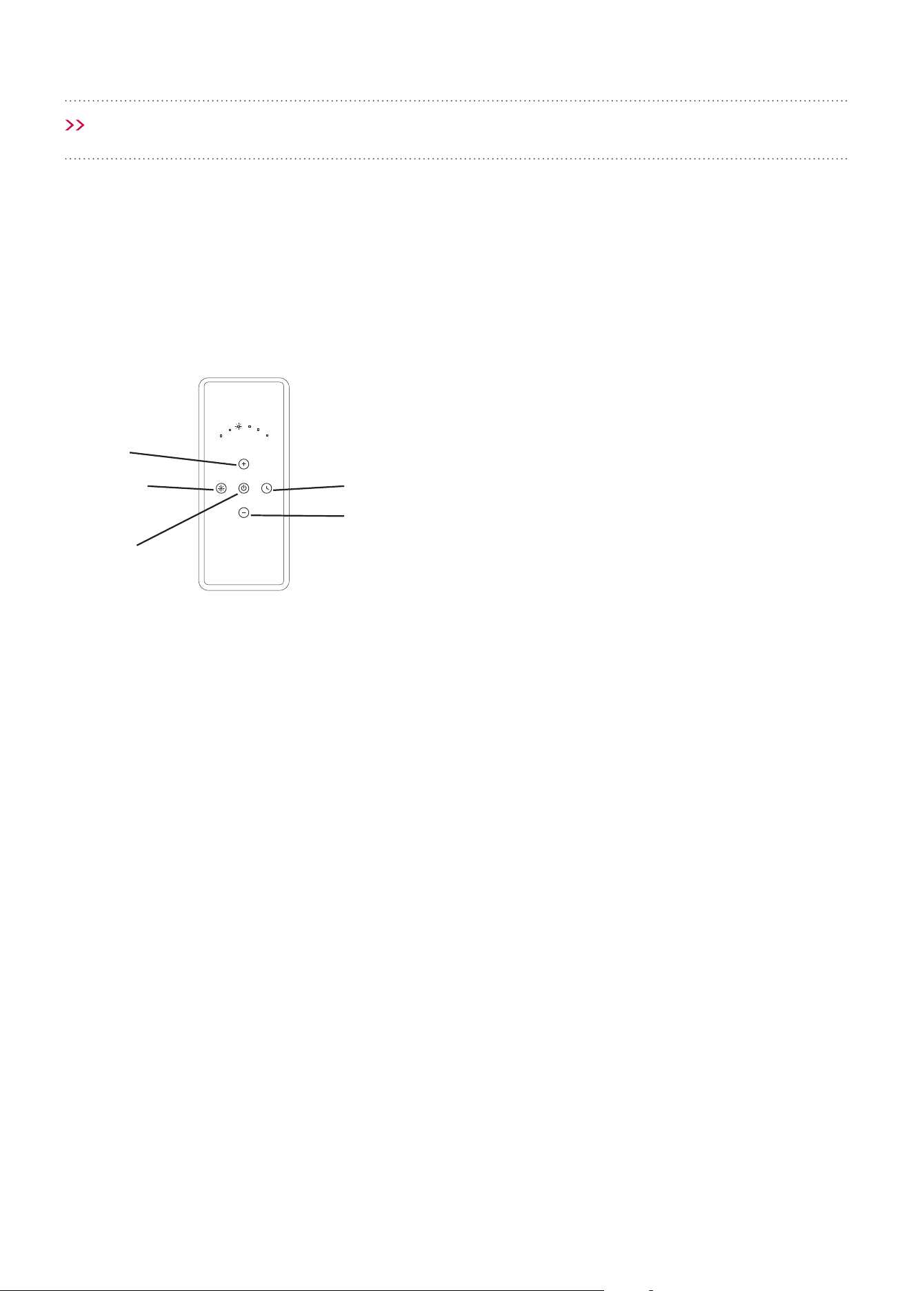
The rangehood has a 4-speed remote control
device. The buttons have the following functions
(valid for all rangehood models with remotes):
A. ON / OFF button: This button turns the
rangehood on and o. The rangehood will always
be turned on at minimum speed.
B. High-speed button: This button increases
the aspiration speed.
C. Low-speed button: This button decreases
the aspiration speed.
NOTE: When increasing and decreasing the speed
of aspiration always wait for 2 seconds after you
have changed the speed to do so again.
D. + button: Activates the deferred stop function
(after 10 minutes the rangehood will automatically
stop).
E. - button: Turns the rangehood lighting on or
o.
If the remote control fails or the batteries
run out, disconnect the rangehood using the
safety switch inside the rangehood (which can be
accessed from one of the lters) and replace the
batteries.
NOTE: To obtain the best performance, turn on
the rangehood a few minutes prior to cooking and
leave it on for at least 10-15 minutes after you have
nished cooking
A
B
C
DE
Page 23
OPERATION
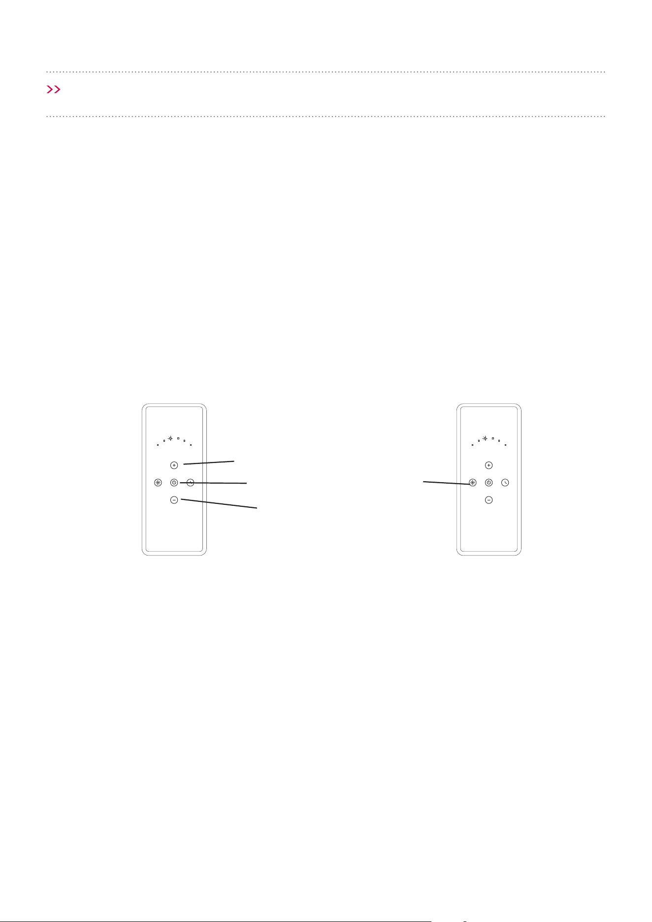
GENERATING A NEW TRANSMISSION
CODE
In the unlikely event that the remote control
interferes with other appliances. You can assign
a new transmission code to prevent this happen.
There are 8 dierent transmission codes for you to
choose from.
1. Press and simultaneously hold buttons A, B
and C until all lights on the remote control
icker at the same time.
2. After all lights light up, press the B and C
buttons and the lights will ash 3 times to
indicate that the process has been completed.
SYNCHRONISATION OF THE REMOTE
CONTROL WITH THE RANGEHOOD
If the remote control fails or the batteries
run out, disconnect the rangehood using the
safety switch inside the rangehood (which can be
accessed from one of the lters) and replace the
batteries, then synchronise the remote.
1. Switch OFF the circuit breaker.
2. Switch ON the circuit breaker.
3. Within the rst 20 seconds of switching the
circuit breaker back ON, please direct the
remote control to the rangehood and hold the
light or “E” button, until the rangehood lights
switch on.
1 2 3 4 1 2 3 4
A
B
C
E
Page 24
FILTERS
• For this appliance to function eectively, regular
maintenance is a must.
• The function of the lter is to absorb the grease
particles emitted during cooking.
• Blocked lters and heavy oil deposits restrict
airow and may cause the motor to overheat and
become a re hazard.
• Filters should be cleaned every 3-6 weeks or
after 40 hours of use depending on use.
• Disconnect the electrical connection before any
maintenance or cleaning processes are carried
out.
• In ceiling-mounted rangehoods, the doors or
glass must be opened before accessing the
lters.
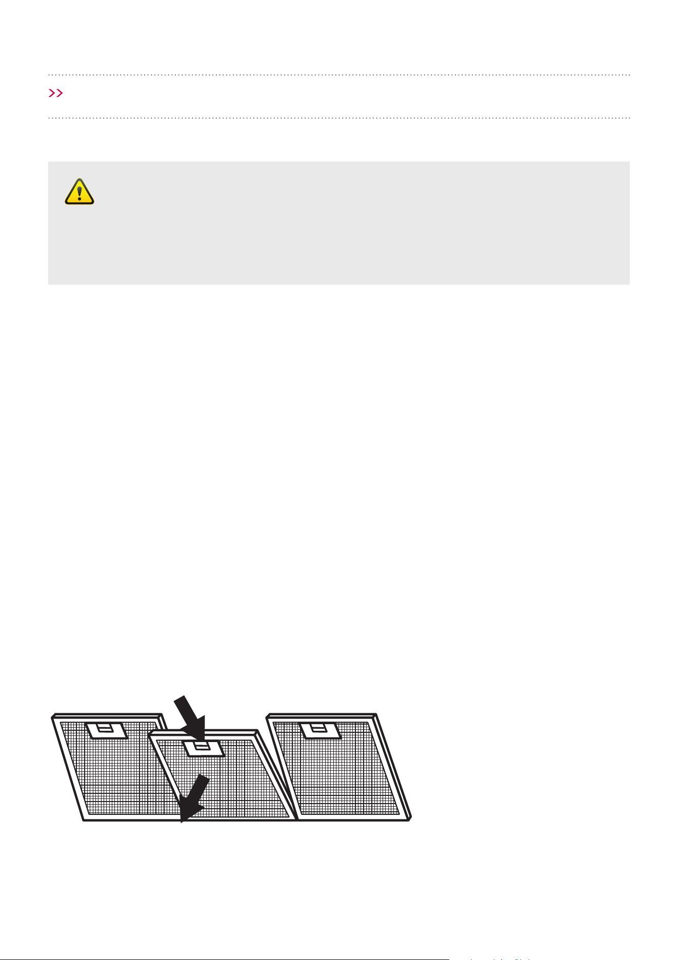
• To remove the lter, press ‘Catch A’ towards the
rear of the rangehood (removing the spring
loaded pins from the front), ease down slightly
and remove. To replace, perform the same
operation but in reverse.
• If you have an induction cooktop, please aim
to clean the lters at least every 10 days,
depending on frequency of use.
• The lters can be washed by hand or in the
dishwasher
Washing by hand - Immerse the lter in hot
water and a suitable detergent, when clean,
rinse with plenty of hot water.
Dishwasher - Put the lter in the dishwasher
and select a short program at low temperature.
NOTE: The colour of the metal mesh lters may
change after several washes. This is normal and
it is not necessary to replace the lters.
WARNING
Always switch o and disconnect power to the rangehood before cleaning. The
manufacturer is exonerated from all responsibility in the event of re due to poor
maintenance of the lters and rangehood.
Cleaning and user maintenance shall not be made by children without supervision.
Latch A
CLEANING AND MAINTENANCE
Catch A
Page 25
CLEANING AND MAINTENANCE
SURFACES
The surface of the rangehood can be cleaned with
warm soapy water and a soft sponge / cloth.
• Never use abrasive detergents, scouring pads,
steel wool or solvents on ANY part of this
appliance.
• Rinse with clean water and ensure that the
appliance is completely dry after cleaning.
• Always make sure the appliance is completely
dry after cleaning and never leave wet, this may
cause irreparable damage.
• For better results, you can use high quality
cleaning and protection products (eg. Steel
Kleen) to clean your rangehood.
It is important to follow the direction of the surface
grain with the cloth (refer to gure below). This is
to reduce any possible marking to the appliance.
Do not pour any liquid directly on to the rangehood,
apply to a soft cloth rst.
The cloth must have no buttons, zips or fasteners
that can scratch the surface.
It is strictly forbidden to use chemical solvents,
aggressive, grainy or abrasive products,
naphtha, alcohol or similar products that could
damage the surface of the rangehood.
The manufacturer will not be held responsible for
functional or aesthetic damage caused
by cleaning with products which are not suitable or
using inadequate cleaning methods.
Cleaning the Interior
Clean the interior of the rangehood with a damp
cloth and a neutral detergent or denatured alcohol.
WARNING
Do not use denatured
alcohol on the exterior of the
rangehood. Do not clean the
electric parts or the motor with
liquids or solvents.
Page 26
CLEANING AND MAINTENANCE
TYPE 3 (LED Plate):
Replacing the LED Plate 11W
(Mod. Modular)
NOTE: Make sure the device is disconnected from
the electrical power supply.
Step 1
Open the door of the Paradigma hood. Remove the
lter and disconnect the light connector.
Your rangehood may have multiple light types, please refer to the pictures below for light replacement.
TYPE 1 (LED Spot) & 2 (GLED Square):
REPLACING THE LED BULB
The life span of an LED bulb is at least 10 times that
of a halogen bulb. If the globe needs to be replaced,
proceed as follows:
1. Unplug the respective connector (A).
2. Press the tabs (B) inside the rangehood.
3. Remove the LED.
4. Put in the new LED and reinstall, as above, but
in reverse order.
A A
B B
Type 1 — LED Spot Type 2 — GLED Square
Light
connector
Screws
Step 2
Remove the door by removing the screws.
WARNING
Always switch o and disconnect the power cord before replacing any light bulbs.
Failure to do so may cause serious injury. Please be aware that the light bulb will retain
heat for a short period of time after being switched o.
Page 27
CLEANING AND MAINTENANCE
Step 3
Remove the screws from the back of the door (the
LED lights are part of the back plate).
Step 4
Replace the back plate (which include the LED
lights).
Step 5
In order to ret the door back on to the rangehood,
repeat process in reverse.
Door screws
LED light
Door screws
Back plate
Back plate

Page 28
TROUBLESHOOTING
COOKING WITH INDUCTION
COOKTOPS
Cooking with an induction or similar cooktop,
may produce condensation on the rangehood.
Unlike basic electric or gas cooking, induction
cooktops heat food and liquid instantly, which in
turn, produces vapours rapidly. Because of this
faster process, the rangehood lters do not have
enough time to warm, which increases the chance
of condensation forming.
There are many variables that may contribute
to condensation forming, some of which include
but are not limited to:
• Variance in climate – geographical location.
• Position of your home & kitchen – morning/
afternoon sun.
• Distance from cooktop to the rangehood.
• Speed of food & liquid heating.
• Angle of ducting – an ‘S’ bend is preferred.
• Filter size – larger rangehood preferred,
as it will have a larger lter area.
• Quality of pots or cookware you are using –
high quality is recommended.
How to reduce the possibility
of condensation forming:
• Ensure the rangehood is installed by a qualied
professional, carefully following the installation
guide.
• Turn on the rangehood 5-10 minutes prior to
cooking, and leave on for 5-10 minutes after
cooking; this helps clear remaining vapours
from the ue.
• Start the cooking process at a low-to-medium
setting and allow time for the rangehood to
become warm.
• Clean lters regularly.
• Ensure constant airow in the cooking zone; this
helps optimise the rate of extraction.
• Follow all induction cooktop manufacturer’s
advice.
For further tips or information regarding cooking
with induction, please contact the induction
cooktop manufacturer.
Page 29
TROUBLESHOOTING
Before you contact the technical service
department, make sure that the product
is plugged in and power is supplied.
• Do not take any action that will damage
the product.
Check electric connection. Voltage of the electric
network should be between 220 - 240V, rangehood
should be connected to grounded plug and turned on.
Please ensure that there is power to the rangehood
and the rangehood is switched on and the motor is
conneted to the rangehood
Check light switch. Light switch should be at on position.
Check lters. The lters should be washed regularly,
see lter cleaning.
Light s should be rmly in position.
Check outlet. Outlet should be open.
Check light s. Make sure they are not broken or faulty.
Please make sure there is no obstruction in ducting or
with the back draft ns.
Check the outlet, make sure it is not blocked and you
have the correct diameter ducting.
Check Isodrive installation manual, make sure the exi
ducting is installed correctly, eg. Length of ducting
used, keep the ducting taut.
Rangehood does
not work
X X
Light does not work X X X X
Rangehood air
exaction is weak
X X X X
Rangehood does
not direct air out
(through chimney)
X X
Loud noise from
the rangehood
X X
IMPORTANT
Never attempt to repair this
appliance by yourself. Always
refer to a qualied Service
Technician.

Page 30
TROUBLESHOOTING
Calling the Technical Assistance Service
Hotline
In the event that the failure is not due to the
faults mentioned in Trouble Shooting, contact
the Customer Service.
In Australia,
Customer Service 1300 829 066
In New Zealand,
Customer Service 0800 200 510
Lodging an online Service Request
In the event that failure is not due the reason/s
in the trouble shooting section, you can lodge an
online Service Request.
To lodge a Service Request, visit our website
www.schweigen.com.au/pages/support/service-
warranty and click on the link to download the
service request form.
A service request will require the following
information:
• The purchase date
• The rangehood model and motor type
• The rangehood serial number or batch
number (this number is on a sticker inside
the rangehood)
• A copy of the purchase receipt (without a receipt
your service request cannot be processed)
FAULTY INSTALLATION
It is not the responsibility of Schweigen Home
Appliances to rectify any incorrect installations.
A service call out fee will be charged for any
Schweigen technician that attends a call, whereby
it is established that the fault is due to an incorrect
installation or non-manufacturing fault. Should the
appliance be installed in such a way that the service
agent is unable to gain access to the appliance,
the person/s who own the premises where the
appliance resides — will be responsible to provide
access to the appliance at their expense.
Page 31
TECHNICAL SPECIFICATIONS
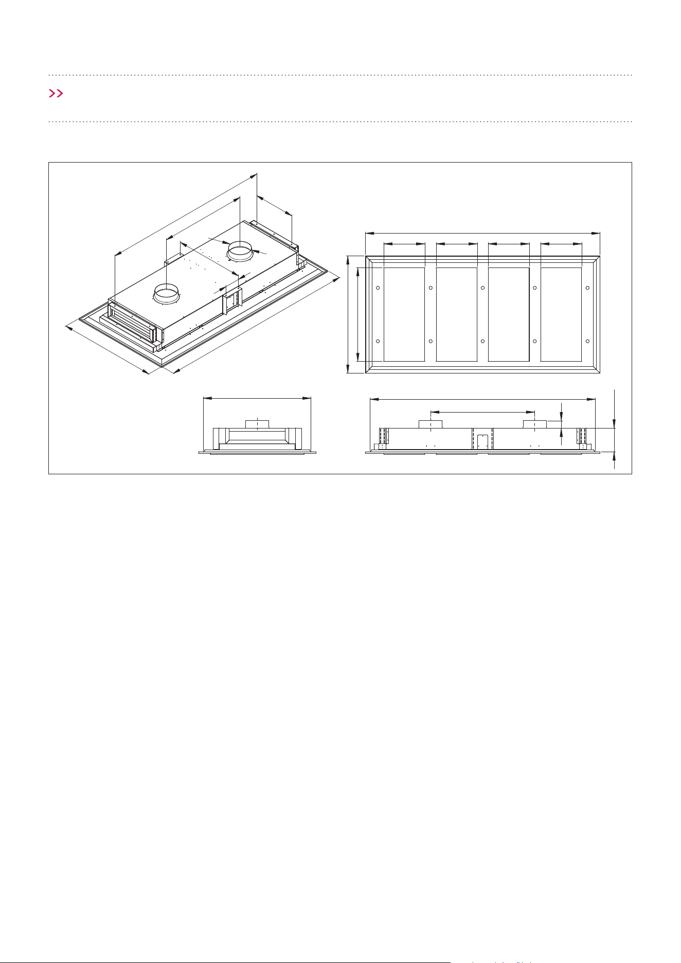
Model: CC-INARTS
Feeding Voltage: 220-240V 50Hz
Max Lamp Power: 10 x GLED Square 55 x 55mm
2.1W 12V 4000k
1710
2000
885
420
ø200
700
1000
Cutout: 950
2000
Cutout: 1950
885
64
Min 210 - Max 335
1000
800
350 350 350 350
150
Page 32
TECHNICAL SPECIFICATIONS
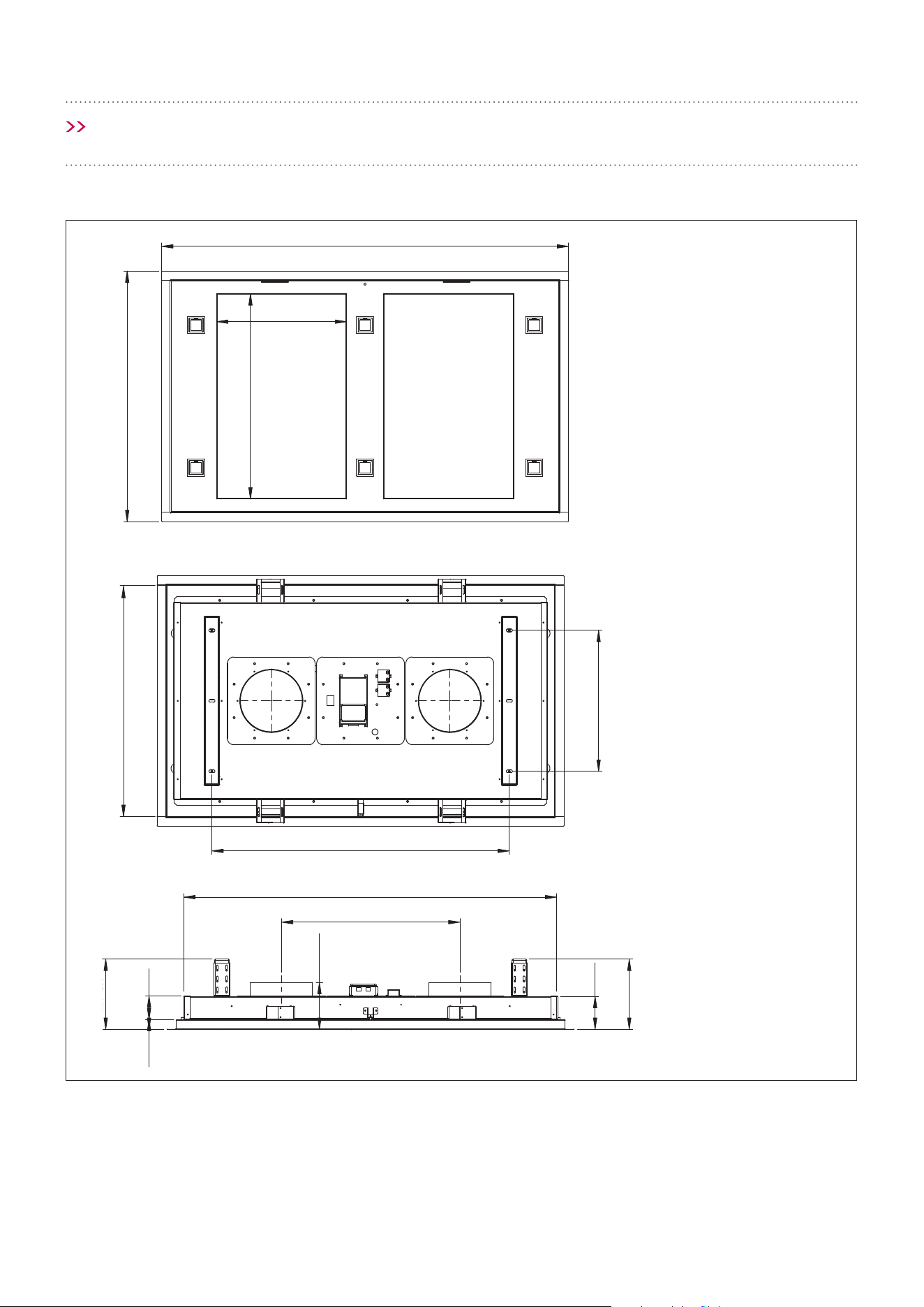
Model: CC-SURF2S
Feeding Voltage: 220-240V 50Hz
Max Lamp Power: 6 x GLED Square 55 x 55mm
2.1W 12V 4000k
125
105.1
MAX – 450
75
655
800
750
450
950
570
415
1300
1250 cutout
31.6
Min – 260
125
105.1
MAX – 450
75
655
800
750
450
950
570
415
1300
1250 cutout
31.6
Min – 260
125
105.1
MAX – 450
75
655
800
750
450
950
570
415
1300
1250 cutout
31.6
Min – 260
1300
800
750
Cutout 1250
655
415
950
570
±125
7531.6
Min - 260
Max - 450
105.1
450
Page 33
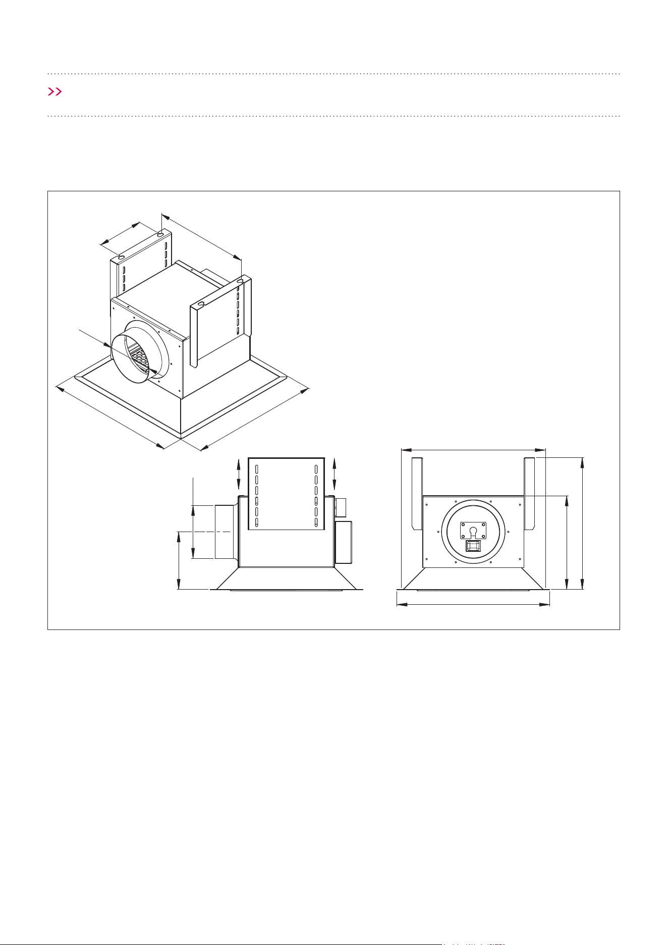
TECHNICAL SPECIFICATIONS
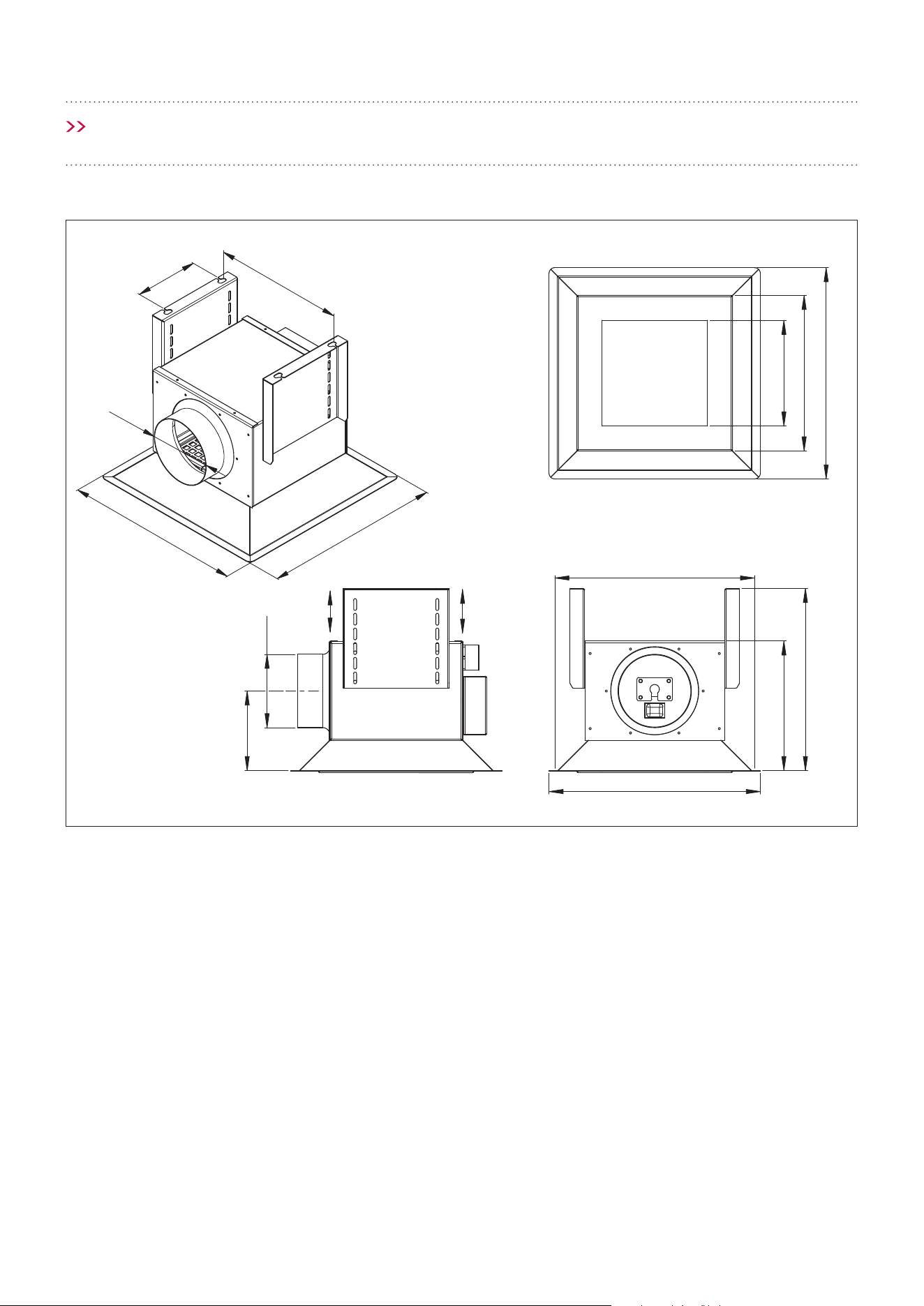
Model: CC-PARA4S
CC-PARA4W
CC-PARA3S
CC-PARA3W
CC-PARA2S
CC-PARA2W
Feeding Voltage: 220-240V 50Hz
Max Lamp Power: 1 x 11W 12V 4000k
(LED Plate) 170 x 170mm
265
130
ø120
ø120
360 360
Cutout 340 x 340
310
360
265
180220
135

Page 34
DISCLAIMER
Under our policy of continuous product
development, product specications may change
without notice. Prospective purchasers should
therefore check with the retailer to ensure this
publication correctly describes the products being
oered for sale. All information supplied is to be
used for general reference purposes only and
is on the understanding that Schweigen Home
Appliances will not be liable for any loss, liability or
damage of whatever kind arising as a result of any
reliance upon such information. All pictures used in
the guide are for illustrative purposes only.
Although our information and marketing states
the term ‘Silent’ for certain models, the following
applies to various models that are sold with
certain Isodrive Systems and bae lters. When a
model with the larger motored Isodrive System is
operated at the higher speed/s air movement may
be heard. For example, while operating on speed
4 & 5 (For 5 speed models) the rangehood may be
audible due to the large amount of air movement
moving through the lters.
*Please make sure that the rangehood and motor
have been installed as per the corresponding
instruction guides in order for optimal performance
(the Isodrive Motor Manual can be found with the
Isodrive Motor, or online at schweigen.com.au).
Schweigen Home Appliances has presented this
information in good faith to all their retailers and
distributors to convey before any/all purchase/s.
Information is supplied upon the condition that the
person/s receiving the information will make their
own determination as to its suitability for their
purpose/s prior to use. In no event will Schweigen
Home Appliances be responsible for damages of
any nature whatsoever resulting from the use of,
or reliance upon, information from their website or
the products to which the information refers.
The symbol on the product or its
packaging indicates that it cannot be
treated as normal household waste.
Take this product to your nearest
electrical and electronic equipment
waste point for recycling. By correctly
disposing of this product, you will
be helping to prevent potentially
negative consequences for the
environment and public health,
which could arise if this product is
not handled in the appropriate way.
For more details about the recycling
of this product please contact the
authorities of your city or town,
your local household waste service
or the store where you purchased
the product.

Page 35
NOTES

www.schweigen.com.au
© Schweigen Home Appliances Pty Ltd. 2018.
Australia
8/3-4 Anzed Court, Mulgrave, Victoria 3170.
Phone: 1300 881 693.
Email: sales@schweigen.com.au.
New Zealand
5 Tolich Place, Henderson, Auckland 0610.
Phone: 0800 200 510.