
1200KG CAPACITY ELECTRIC VEHICLE (EV)
BATTERY HYDRAULIC HIGH LIFTING TABLE
Thank you for purchasing a Sealey product. Manufactured to a high standard, this product will, if used according to these
instructions, and properly maintained, give you years of trouble free performance.
IMPORTANT: PLEASE READ THESE INSTRUCTIONS CAREFULLY. NOTE THE SAFE OPERATIONAL REQUIREMENTS, WARNINGS & CAUTIONS. USE
THE PRODUCT CORRECTLY AND WITH CARE FOR THE PURPOSE FOR WHICH IT IS INTENDED. FAILURE TO DO SO MAY CAUSE DAMAGE AND/OR
PERSONAL INJURY AND WILL INVALIDATE THE WARRANTY. KEEP THESE INSTRUCTIONS SAFE FOR FUTURE USE.
Refer to
instructions
Wear safety
footwear
1. SAFETY
1.1. ELECTRICAL SAFETY
WARNING! It is the user’s responsibility to check the following:
9 Check all electrical equipment and appliances to ensure that they are safe before
using.
9 Inspect power supply leads, plugs and all electrical connections for wear and
damage.
9 Ensure that the insulation on all cables and on the appliance is safe before
connecting it to the power supply.
8 DO NOT use worn or damaged cables, plugs or connectors.
9 Ensure that any faulty item is repaired or replaced immediately by a Sealey qualied technician.
9 If the cable or plug is damaged during use, switch o the electricity supply and remove from use.
9 Sealey recommend that an RCD (Residual Current Device) is used with all electrical products.
IMPORTANT: Ensure that the voltage rating on the appliance suits the power supply to be used and that the plug is tted with the
correct fuse.
8 DO NOT pull or carry the appliance by the power cable.
8 DO NOT pull the plug from the socket by the cable.
WARNING! Any modications to the machine must not be performed without prior written approval from the manufacturer.
Unauthorized modications may compromise safety, void warranties, and violate compliance with applicable standards.
1.2. GENERAL SAFETY
WARNING! Ensure all Health and Safety, local authority, and general workshop practice regulations and recommendations are strictly
adhered to when lifting or moving heavy loads. The lifting or movement of heavy loads may be dangerous if not undertaken correctly.
Trained users only.
9 Familiarise yourself with the application and limitations, as well as the specific potential hazards peculiar to the lift.
9 Maintain the lift in good condition (use an authorised service agent).
9 Replace or repair damaged parts. Use genuine parts only. Unauthorised parts may be dangerous and will invalidate the warranty.
9 Use a qualified person to lubricate/maintain the lift.
DO NOT
use brake fluid to top up hydraulic unit. Use Sealey hydraulic oil only.
9 To ensure optimal and safe performance, always keep the lift clean and well-maintained. Use the lift only on flat, level, solid ground,
preferably concrete, as using it on Tarmacadam when fully laden may cause the wheels to sink.
WARNING! Position the lift in a suitable working area, keeping the space clean, tidy, and free from unrelated materials. Before
transporting a load, always lower it fully and conduct a risk assessment of the intended route. Make sure the floor is swept clean and free
from obstacles to allow safe movement.
9 Keep the work area clean, uncluttered and ensure there is necessary adequate lighting.
9 Keep children and non essential persons away from the loading/unloading and transporting area.
9 Keep hands and body clear of the edge and underside of the platform when operating the lift.
9 Maintain correct balance and footing. Ensure the floor is not slippery and wear non-slip shoes.
8 DO NOT enter under the platform unless it is mechanically locked.
WARNING! Ensure load is placed level and centrally on lift platform and if necessary strap load in place before attempting to lift, lower, or
transport. When raised, check that the platform/load will not foul on the handle and/or your hand when lowering the load.
WARNING! Use the lift with diligence. DO NOT allow lift to knock into anything. Even when unladen, the lift is heavy and if misused, could
cause serious damage and/or personal injury. Continually monitor transportation, lifting and lowering operations.
9 Take care to ensure you can view the way ahead when moving the lift. Take special care when approaching blind corners.
9 Before lifting check that there are no overhead obstructions.
8 DO NOT use in strong winds.
9 Only use in an area with adequate lighting.
9 Engage the wheel locks before attempting to raise or lower the platform.
▲ DANGER! If a heavy load tips or leans, STOP WHAT YOUR ARE DOING. Move quickly to a safe distance. DO NOT try to hold or steady
a heavy load. Failure to follow this instruction may cause serious personal injury or death.
9 Ensure the lift is fully lowered before attempting to transport a load.
9 Before lowering the platform, ensure there are no obstructions underneath the platform and that all persons are standing clear of the lift.
Watch the lift during operation.
DO NOT enter
under if not
mechanically
locked
DO NOT put
hands or feet
under platform
DO NOT ride
on platform
Wear
protective
gloves
No reaching in
Keep hands
clear
Pinch point
Original Language Version
© Jack Sealey Limited
EVBT1200 Issue 2 22/05/25
MODEL NO: EVBT1200
Indoor use only DO NOT use
on uneven or
inclined oors

9 The lowering speed operates at a fixed rate regardless of the load weight and can be stopped at any time by releasing the Down arrow on
the controller.
WARNING! DO NOT exceed the rated capacity of the lift.
9 Ensure loads are evenly placed on the lift platform.
8 DO NOT use the lift if a part is missing or damaged.
8 DO NOT ride on the lift or allow any person to be transported on the lift.
8 DO NOT use the lift for any purpose other than lifting, lowering and transporting loads.
8 DO NOT allow lift to free wheel in transit. Always propel and control the lift by using the handle.
8 DO NOT use the lift on sloping surfaces.
8 DO NOT operate the lift when you are tired or under the influence of alcohol, drugs or intoxicating medication.
8 DO NOT allow children to operate the lift.
8 DO NOT adjust or tamper with the hydraulic safety valve.
8 DO NOT place any part of your body within or under the lift platform whilst raising and when lowering.
9 When not in use, fully lower the platform and store in a safe, dry, childproof area.
9 Firefighting: Refer to MSDS.
1.3. FREQUENCY AND METHODS OF SAFETY SYSTEM CHECKS
All safety checks must be performed by trained personnel. Any faults or abnormalities must be reported and corrected before operating
the equipment.
1. Daily Checks (Before Each Use):
- Visual inspection of emergency stop button, safety interlocks, and guard systems.
- Function test of emergency stop.
- Check for loose connections, damaged cables, or visible wear.
2. Weekly Checks:
- Inspect all safety devices for signs of tampering or malfunction.
3. Monthly Checks:
- Perform a full operational check of the safety system under simulated conditions.
- Test the fail-safe features to ensure the system behaves as expected in the event of a fault.
4. Annual Inspection (by Qualified Personnel):
- Comprehensive inspection and testing of all electrical and mechanical safety.
1.4. CONDITION OF THE MACHINE
To ensure safe and efficient operation, the machine must be maintained in good working condition at all times. Regular inspection should
confirm the following:
1.4.1. STRUCTURAL INTEGRITY:
9 No signs of cracks, corrosion, or deformation on the frame, lifting arms, or platform.
1.4.2. HYDRAULIC SYSTEM:
9 No leaks from hoses, cylinders, or fittings. Fluid levels should be within specified limits.
1.4.3. WHEELS AND CASTORS:
9 Free from damage, excessive wear, or obstruction. Castors should rotate and lock as intended.
1.4.4. ELECTRICAL COMPONENTS:
9 Wiring, connectors, and control panels must be intact, with no exposed or frayed wires.
1.5. SAFETY DEVICES:
9 All safety interlocks, emergency stop buttons, guards, and limit switches must be fully functional.
1.6. SURFACE CONDITION:
9 Platform and surfaces should be clean, free from oil, debris, or damage that could impact stability or operation.
1.7. INFORMATION FOR EMERGENCY SITUATIONS
WARNING! In the event of an accident or breakdown, immediately stop the machine, activate the emergency stop, and follow the site’s
emergency procedures while notifying a qualified technician.
1.8. SOURCES OF DANGER
- Pinch Points: Risk of injury from moving parts such as scissor arms and tilt mechanisms.
- Crushing Hazards: Under raised platform or during lifting/lowering operations.
- Electrical Hazards: Improper handling of the power supply or damaged cables.
- Instability: Overloading or unevenly placed loads may cause tipping or shifting.
- Hot Surfaces: Certain components may become hot during extended use.
- Unauthorized Modifications: May compromise safety and machine functionality.
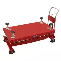
2. INTRODUCTION
Heavy-duty construction, solid steel framework. High lift version, 1780mm maximum platform height. Powerful electric motor, for
smooth controlled ascent and descent. Hand control with a safety stop feature. Multiple adjustments can be made to the table and
saddles, for the removal and installation of most EV vehicle batteries. Fitted with four composite wheels. Two xed and two locking
castors for easy rolling over rough workshop oors. Designed to assist with EV battery maintenance on electric vehicles. Can also
be used for assisting with many other day-to-day workshop tasks such as removing/installing engines, transmissions, fuel tanks,
subframes and can be used as a mobile service bench. This item is heavy. Extra assistance must be provided at the delivery point to
help its safe delivery.
Original Language Version
© Jack Sealey Limited
EVBT1200 Issue 2 22/05/25
3. SPECIFICATION
Model No: EVBT1200
Capacity: 1200kg
Declaration of Conformity: 2006/42/EC
EN ISO 12100:2010
EN ISO 3691-5:2015/A1:2020
Rated Voltage: 220V
Fuse Rating: 13A
Number of Phase: Single Phase
Maximum Platform Height: 1780mm
Frequency: 50Hz
Full-Load Current: 8A
Cable Length: 5m
Minimum Platform Height: 650mm
Nett Weight: 460kg
Platform Length: 1340mm
Platform Width: 650mm
Plug Type: 3-Pin BS
Wheel Bore Size: Ø12mm
Wheel Size: Ø150mm
Original Language Version
© Jack Sealey Limited
EVBT1200 Issue 2 22/05/25
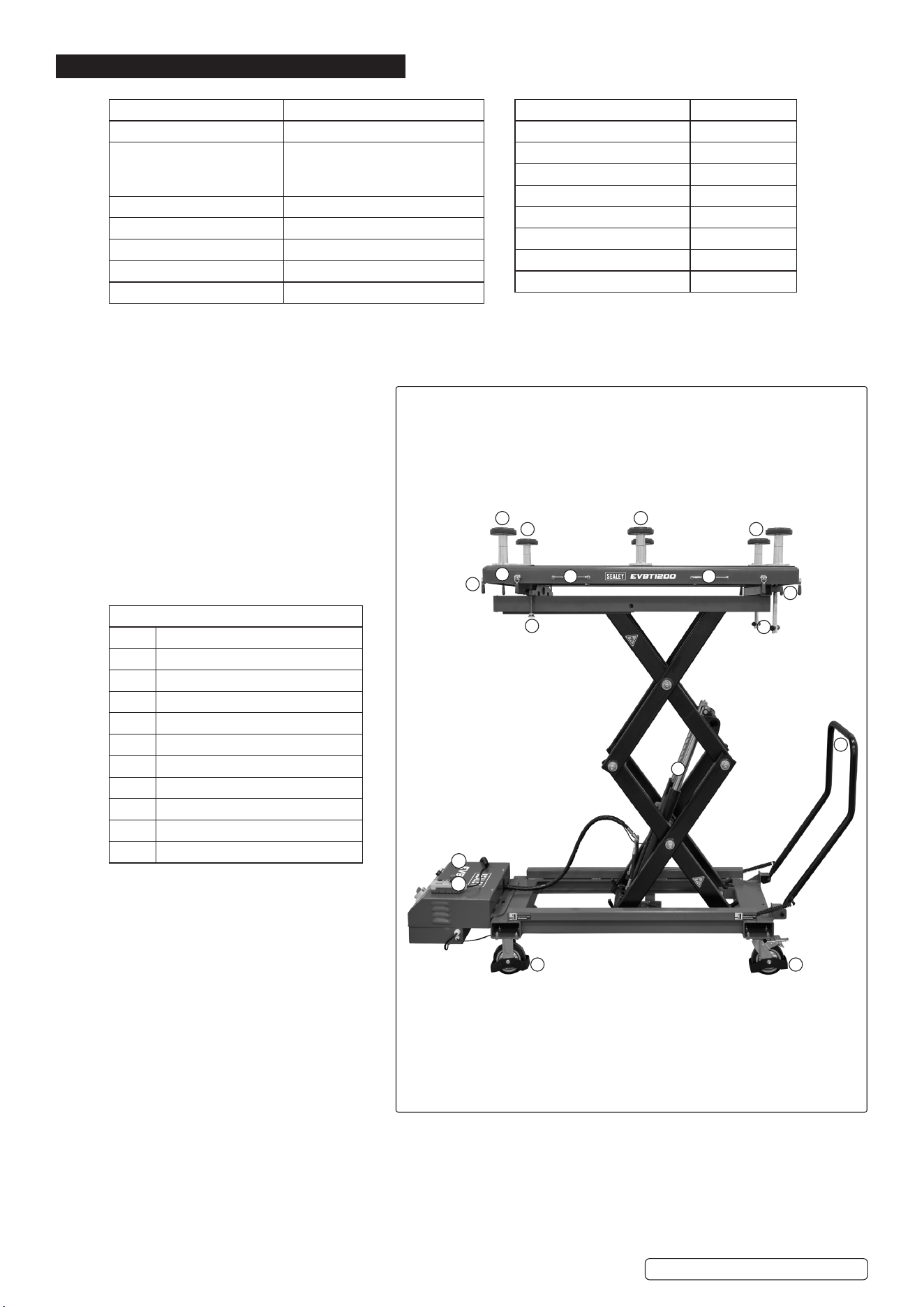
EVBT1200
EVBT1200
1 Supporting Pads.
2 Tabletop Locks.
3 Tabletop
4 Handles.
5 Stability Screw.
6 Drive Screw.
7 Hydraulic Cylinders.
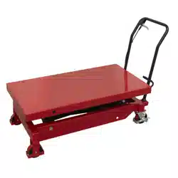
8 Main Handle.
9 Castor Wheels.
10 Control Panel.
11 Main Isolator Panel.
1
3
2
5
4 4
6
2
7
8
99
11
10
1
1
1
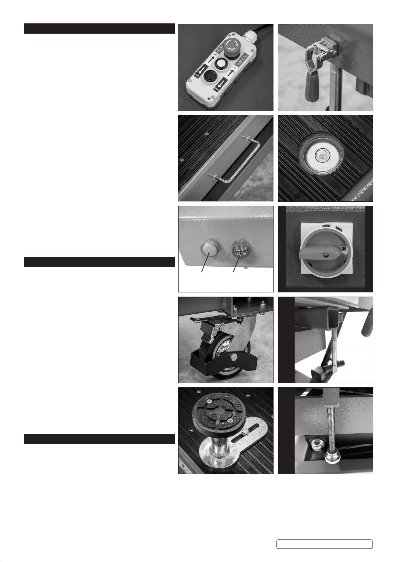
4. FEATURES
A. The control panel is used to lift and lower the
table top and includes an Emergency Stop function.
B. Tabletop Locks (x8):
Twist to adjust, then fold the elbow down to lock
securely.
C. Handle:
Used to safely manoeuvre and position the table.
D. The levelling bubble ensures the tabletop is level
before operation.
E. Display indicator lights (green and red/beeps and
ashes) show the machine’s operational status.
F. Main Isolator On/O Switch:
Used to disconnect or restore power to the machine
for maintenance or emergency purposes.
G. Lockable Castor Wheel (x2):
Allows the machine to be moved easily and locked
securely in place during operation.
H. Drive screw:
Used to tilt the table. Fully screw the drive screw in
and out to ensure the table’s tilt function operates
correctly.
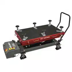
I. Supporting Pads:
Located on top of the table, these pads help stabilize
and protect the load during lifting and positioning.
Their positions are adjustable to accommodate
dierent load sizes and shapes.
J. Stability Screw Adjustment:
Screw the stability screw into the threaded hole
approximately ve turns. When this function is not
in use, ensure the screw is not extended out of the
square tube.
5. ASSEMBLY
5.1. TRANSPORT (DELIVERY): Very heavy item.
Ensure fork lift or appropriate lifting equipment is
available at delivery point.
5.2. UNPACKING: Remove all packaging materials and
take out the blocks used to secure the wheels during
transport.
NOTE: The trolley comes fully assembled except for
the main handle.
5.3. MAIN HANDLE: Attach the main handle to the frame
using the supplied hardware, ensuring it is securely
fastened before use.
5.4. FUNCTION CHECK
Hydraulic System and Shear Rod Mechanism
Test (No Load):
Before initial use, cycle the hydraulic system and
shear rod mechanism several times without any load
to ensure proper operation.
1. Press the Up button to raise the platform to its
highest position.
2. Press the Down button to lower the platform to its
lowest position.
Repeat this process a few times to conrm smooth
and complete movement.
6. OPERATION
Consult manufacturer’s data before attempting any
operation.
WARNING! Ensure you read, understand and follow
the safety instructions. Ensure all Health and Safety,
local authority, and general workshop practice
regulations and recommendations are strictly adhered to when lifting or moving heavy loads.
The lifting or movement of heavy loads may be dangerous if not undertaken correctly.
WARNING! Before each use, inspect the unit: for damage, leaks or any indication that components are NOT working as they should,
that the warning markings are in place and are legible.
Risk assess any operation before applying a load. Consider working area and the path the load will make.
Test the operation of the lift before applying a load.
WARNING! NOTE: WITH OR WITHOUT A LOAD, ALWAYS TRANSPORT THE LIFT WITH PLATFORM IN ITS LOWEST POSITION.
Original Language Version
© Jack Sealey Limited
EVBT1200 Issue 2 22/05/25
A B
C D
E F
G H
I J
Green Red
6.1. POSITION OF CENTRE OF GRAVITY:
The load’s centre of gravity should be positioned centrally on the platform to ensure balance and safe lifting. Uneven distribution may
aect stability and lead to unsafe operation.
6.2. FINE ADJUSTMENT TILTING FEATURE
The forcing screws shown in Figure H on previous page allow the user to nely tilt the platform to assist with removing or installing
vehicle components. This feature helps compensate for uneven shop oors, dicult fastener locations, and similar challenges. The
forcing screws can be operated by hand, wrench, or socket, depending on the applied load.
CAUTION: To prevent equipment damage, DO NOT tilt the platform unless the levelling screws are in their lowest position, as the
platform may be driven into the screws.
6.3. STABILIZATION FEATURE
If the lift is being used as a stationary work surface for servicing components, two leveller screws shown in Figure J on previous page
are provided to help stabilize the platform.
Once the desired tilt or platform position is set, thread both leveller screws inward until they make contact with the underside of the
platform. Tighten them nger-tight only to create two additional points of contact, enhancing platform stability during use.
6.4. RAISING THE PLATFORM
NOTE: Ensure that all obstructions are removed and there is sucient space for manoeuvring
the platform safely.
6.4.1. When preparing to lift the platform, ensure that the castor wheels are locked in place.
6.4.2. Position the lifting table under the vehicle and connect electrical power to the power socket.
Then, turn the main isolator switch (F) to the ON position. The green indicator light will
illuminate, conrming power is supplied to the unit.
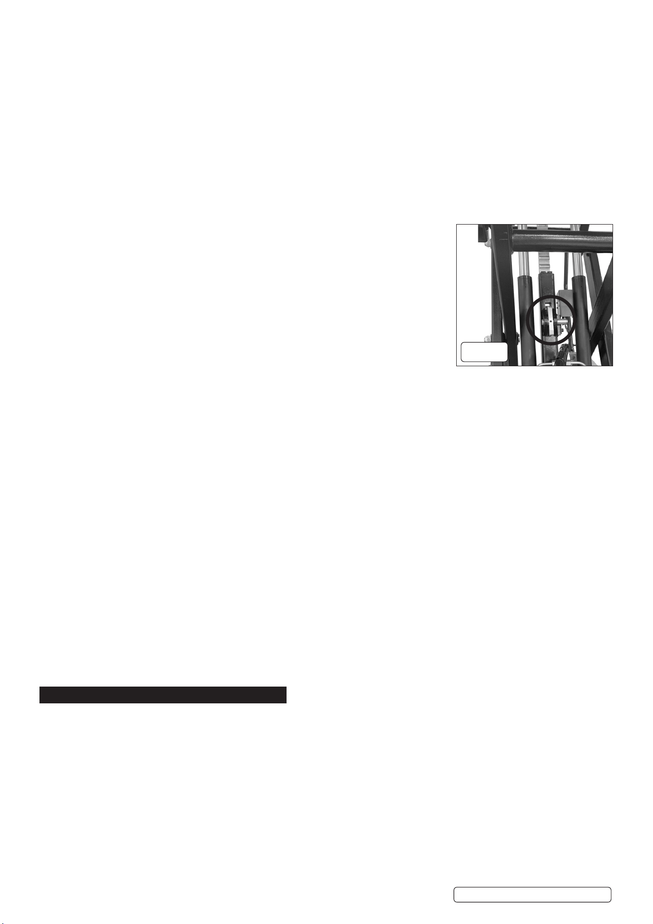
6.4.3. Press the UP button (A) to raise the lifting table until it is close to the load. Release the button
to stop the operation at any time. NOTE: The locking mechanism will engage automatically at
set height increments and will release when lowering the platform. See Fig. 1
6.4.4. LOWERING THE PLATFORM
6.4.5. Press the Down arrow on the control panel to lower the platform. The red indicator light will
ash, and an audible beep will sound during descent. Release the button to stop the operation
at any time.
6.5. EMERGENCY STOP (E-Stop)
6.5.1. The E-Stop on the control panel immediately shuts down all machine operations when
pressed, ensuring user safety in the event of an emergency or malfunction. It must be reset before the machine can be used again.
IMPORTANT: Use the E-Stop only in emergency situations.
6.6. RESTART PROCEDURE AFTER AN UNEXPECTED STOP
1. Identify the Cause:
Inspect the machine for any visible issues (e.g. obstruction, overload, electrical fault, or triggered safety device).
2. Check the Emergency Stop (E-Stop):
If the E-Stop was pressed, turn or pull it to reset, depending on the type of switch.
3. Inspect Indicator Lights:
Observe the control panel for warning lights or error signals that may indicate the issue.
4. Ensure Safe Conditions:
- Remove any obstructions.
- Conrm that the load is secure.
- Verify that there is no risk to personnel.
5. Power Reset:
If necessary, switch the main isolator to OFF, wait 10 seconds, and turn it back to ON.
6. Reconrm Controls:
Ensure all control switches (e.g. Up/Down buttons) are in their neutral position.
7. Resume Operation:
Once the issue is resolved and the system is reset, resume operation as normal by pressing the appropriate control button.
IMPORTANT: If the issue persists, DO NOT attempt further restarts. Contact Sealey Service Centre.
6.7. SAFE HANDLING OF LOADS
- Ensure the load is within the rated capacity of the equipment.
- Position the centre of gravity centrally on the platform for balanced lifting.
- Secure the load properly to prevent shifting or movement during operation.
- Avoid sudden movements or impacts while handling the load.
- Always use appropriate personal protective equipment (PPE) when loading or unloading.
7. MAINTENANCE
IMPORTANT: Only fully qualied personnel should attempt maintenance or repair of the lift and it’s hydraulic system.
WARNING! The markings and safety labels MUST remain in place and legible.
7.1. SERVICING OPERATIONS FOR WHICH NO SPECIFIC SKILLS ARE REQUIRED
The following basic maintenance tasks may be performed by operators without specialized training, provided they follow all safety
instructions:
- Visual inspections for damage, leaks, or wear on cables, wheels, and platform components.
- Cleaning the platform and control panel using a dry or slightly damp cloth.
- Checking and tightening visible fasteners (e.g., bolts, screws) as needed.
- Lubricating accessible moving parts as indicated in the maintenance schedule. Apply grease to the nipples on the ram.
- Inspecting indicator lights and control functions for proper operation.
- Verifying wheel locks and levelling screws for smooth operation.
7.2. PREVENTATIVE MAINTENANCE MEASURES TO BE OBSERVED
Preventative maintenance involves regularly inspecting, cleaning, and checking the machine to ensure all components and safety
systems are functioning correctly.
Original Language Version
© Jack Sealey Limited
EVBT1200 Issue 2 22/05/25
g.1
7.3. CHANGING WHEELS
To change a wheel, disconnect the power, safely lift the machine if necessary, remove the old wheel by loosening the bolts, t and
securely tighten the new wheel, then lower the machine and inspect for proper operation.
7.4. MAINTENANCE AND REPAIR OF THE HOSES
Maintenance and repair of the hoses should only be carried out by the Sealey Service Centre or authorised qualied personnel to
ensure safety and compliance with manufacturer standards.
7.5. PERFORMING MAINTENANCE ON THE MACHINE AND IT’S FITTINGS
Maintenance should be carried out only by the Sealey Service Centre.
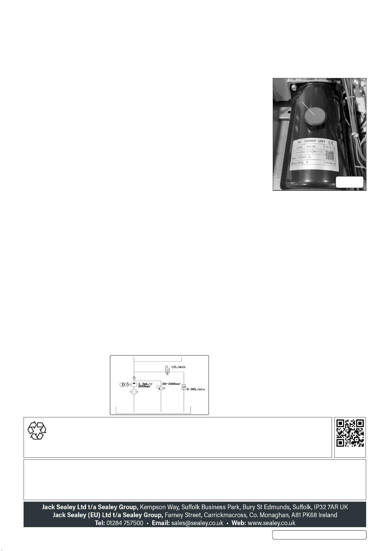
7.6. ELECTRICAL-HYDRAULIC PUMP (g.2)
8 DO NOT exceed the hydraulic pressure rating indicated on the pump data plate, and DO NOT
tamper with the internal high-pressure relief valve. Exceeding the rated pressure may result in
serious personal injury.
Before relling the hydraulic uid, ensure all cylinders are fully retracted to prevent overlling
the reservoir. Overlling can cause excessive internal pressure, leading to uid discharge and
potential injury when the system is operated.
7.7. ACCESSING THE PRODUCT FOR MAINTENANCE WHILE WORKING AT HEIGHT
When accessing the product for maintenance while working at height, always use appropriate
fall protection equipment and ensure that a stable, secure platform or access system is in
place. Maintenance personnel must be trained and competent in working at height procedures.
The area around the equipment should be cordoned o to prevent unauthorized access, and
tools or components must be secured to prevent falling. Never attempt maintenance at height
during adverse weather conditions or without proper risk assessment and supervision.
7.8. SPACE REQUIRED FOR THE REMOVAL OR SERVICING
For the safe removal or servicing of a 1200 kg electric vehicle battery using a hydraulic high-
lifting table, a minimum clear oor area of approximately 4.0 meters by 3.2 meters (12.8 m²) is
recommended, with at least 3.0 meters of overhead clearance. This space allows for the lifting table footprint, operator access, and tool
maneuverability. Side and front/back clearances of at least 1.0 meter each are necessary to ensure safe handling, proper alignment,
and room for technicians to work eciently around the battery and lifting equipment.
7.9. SPARE PARTS
Always use genuine manufacturer-approved spare parts when performing maintenance or repairs. The use of non-approved
components may compromise the safety, performance, and warranty of the equipment. Refer to the spare parts diagrams for correct
identication and ordering.
7.10. TRANSPORT, HANDLING AND STORAGE
The machine must be transported, handled, and stored on a level surface using appropriate lifting equipment, ensuring it is secured to
prevent movement or damage.
7.11. FOR PROLONGED SHUTDOWN AND STORAGE
For prolonged shutdown and storage, thoroughly clean and inspect the truck, secure uids, store it in a dry, covered area with wheels
chocked and brakes engaged, and perform periodic checks during storage.
7.12. ENVIRONMENTAL LIMITATIONS
The machine must be operated and stored in dry, well-ventilated areas, away from extreme temperatures, moisture, corrosive
substances, and explosive atmospheres.
7.13. PROPER DISASSEMBLY AND HANDLING:
Disassemble the machine carefully following the manufacturer’s instructions, handle all components with care to avoid damage, and
store or dispose of parts according to safety and environmental guidelines.
7.14. END OF LIFE
At the end of its service life, this equipment must be disposed of in accordance with local regulations and environmental guidelines.
Components should be separated and recycled where possible. Hazardous materials, such as hydraulic uids or lubricants, must
be handled and disposed of responsibly. Contact your local waste management authority or recycling center for guidance on proper
disposal procedures.
7.15. ELECTRICAL DIAGRAM
ENVIRONMENT PROTECTION
Recycle unwanted materials instead of disposing of them as waste. All tools, accessories and packaging should be sorted,
taken to a recycling centre and disposed of in a manner which is compatible with the environment. When the product
becomes completely unserviceable and requires disposal, drain any fluids (if applicable) into approved containers and
dispose of the product and fluids according to local regulations.
REGISTER YOUR
PURCHASE HERE
Note: It is our policy to continually improve products and as such we reserve the right to alter data, specifications and component parts without prior
notice. Please note that other versions of this product are available. If you require documentation for alternative versions, please email or call
our technical team on technical@sealey.co.uk or 01284 757505.
Important: No Liability is accepted for incorrect use of this product.
Warranty: Guarantee is 12 months from purchase date, proof of which is required for any claim.
Original Language Version
© Jack Sealey Limited
EVBT1200 Issue 2 22/05/25
g.2
Fill plug