
Installation Manual
H-Oven 550
H-Oven 350


WELCOME
This installation manual is designed for kitchen manufacturers who will deal
with these products. To ensure safety and get the best results, please read
this manual carefully, including safety instructions, and keep it for future re-
ference. Before proceeding with installation, take note of the serial number,
as you may need it in case of repairs. Check for any damage during transport
and consult a technician if in doubt before using. Always keep all packing
material away from children.
NOTE: Features, pictures in the manual and product accessories may vary
depending on the model purchased.
i
1
HOOVER
Index
1 Safety warnings for installation p. 2-3
2 Where to install the product p.3
3 Oven dimensions p.4-5
4 Dimensions of combinable products p.6-11
4.1 Compact oven h45 drop down opening
4.2 Compact oven h38 side wing opening
4.3 Warming drawer
5 Installation tools p.12
6 Furniture and ventilation p.12-19
6.1 Precautions
6.2 Undertop installation
6.3 Combination with cooktop
6.4 Corner installation
6.5 Installation oven in column
6.6 Installation compact oven in column
6.7 Installation compact oven + warming drawer in column
6.8 Drawer adjustments
6.9 Installation oven + compact oven h45 in column
6.10 Installation oven + compact oven h38 in column
7 Connection to the mains p.20-23
7.1 Safety warnings
7.2 Instructions
7.3 Other tips
8 Instructions for Oven installation p.24-29
8.1 Important warnings
8.2 Fixing to the cabinet
8.3 Installation step by step
9 Delivery to the user p.30
10 First startup p.30
11 Disassembling the product p.30

2
HOOVER
Safety warnings for installation
Observe these directions before beginning the assembly of the product.
• Your safety is very important to us. Please read this information carefully
before using the oven;
• Installation must be carried on by a qualied technician who must know and
respect the laws in force in the country of installation and the manufactu-
rer’s instruction;
• If manufacturer service is required to eliminate faults resulting from impro-
per installation, such service is not covered by the x;
• Remove the packing material before operating the appliance;
• After unboxing the appliance, always check it is not damaged, in case of is-
sue contact the customer service before installing and do not connect to the
power supply;
• A damaged product can be the cause of a short circuit, electric shock, re
start and other hazards;
• Check the packaging for accessories or accompanying materials (envelopes
with screws, documents, brochures, etc.) and, if so, remove and store them;
• The oven can be located high in a column or under a worktop;
• Before xing, you must ensure good ventilation in the oven space to allow pro-
per circulation of the fresh air required for cooling and protecting the internal
parts. Make the openings specied on the illustrations according to the type
of tting. Always x the oven to the furniture with screws provided with the
appliance;
• No additional operation/setting is required in order to operate the appliance
at the rated frequencies;
• The appliance must not be installed behind a decorative door in order to avoid
overheating;
• If the assistance of the manufacturer is required to rectify faults arisin-
gfrom incorrect installation, this assistance is not covered by theguarantee.
The installation instructions for professionally qualied personnel must be
followed;
• Incorrect installation may cause harm or injury to people, animals or belon-
gings. The manufacturer cannot be held responsible for such harm or injury;
• Safe use is only guaranteed if installation has been carried out properly
according to these instructions. In case of damage due to improper instal-
lation, the responsibility lies with the person who installed the product;
• During installation the oven should be disconnected from the mains to avoid
overheating;
1

3
HOOVER
Where to install the product
• During installation do not use the oven door’s handle to lift and move the oven;
• It is recommended to wear protective gloves during installation to avoid cut
injuries;
• The installation furniture and the adjacent ones must withstand temperatu-
res of 95°C;
• Warranty does not cover damage caused by improper installation;
• In case of incorrect installation, tampering with the device and improper
connection, the validity of the product warranty will expire;
• Make sure that when the product’s power supWply cable is completed, it is
not accessible;
• After assembly, the power cord must not come into contact with moving
parts of kitchen components (such as a drawer) and must not be exposed to
mechanical stresses;
• This product requires constant ventilation during use. Do not cover the air vents;
• When delivering the product to the end user, the technician must ensure that
it has been installed correctly.
• Install and use this product in a closed, covered, dry and well-ventilated
environment;
• Do not install the product in open environments exposed to atmospheric agents;
• This appliance is designed to be used at altitude lower than 2000m;
• Mount the product near an electrical outlet;
• Use the product only when placed in a recessed compartment, otherwise you
risk injury and burns.
2
Cable 1100 mm
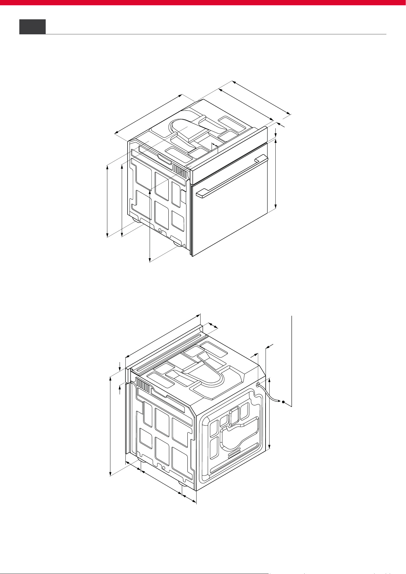
484,5
595
100
83
595
355
99
114
60
9
478,5
575
20
548
550
568
570
565
60
4
HOOVER
Frontal axonometric view
3
Back axonometric view
Oven Dimensions
Dimensions in mm
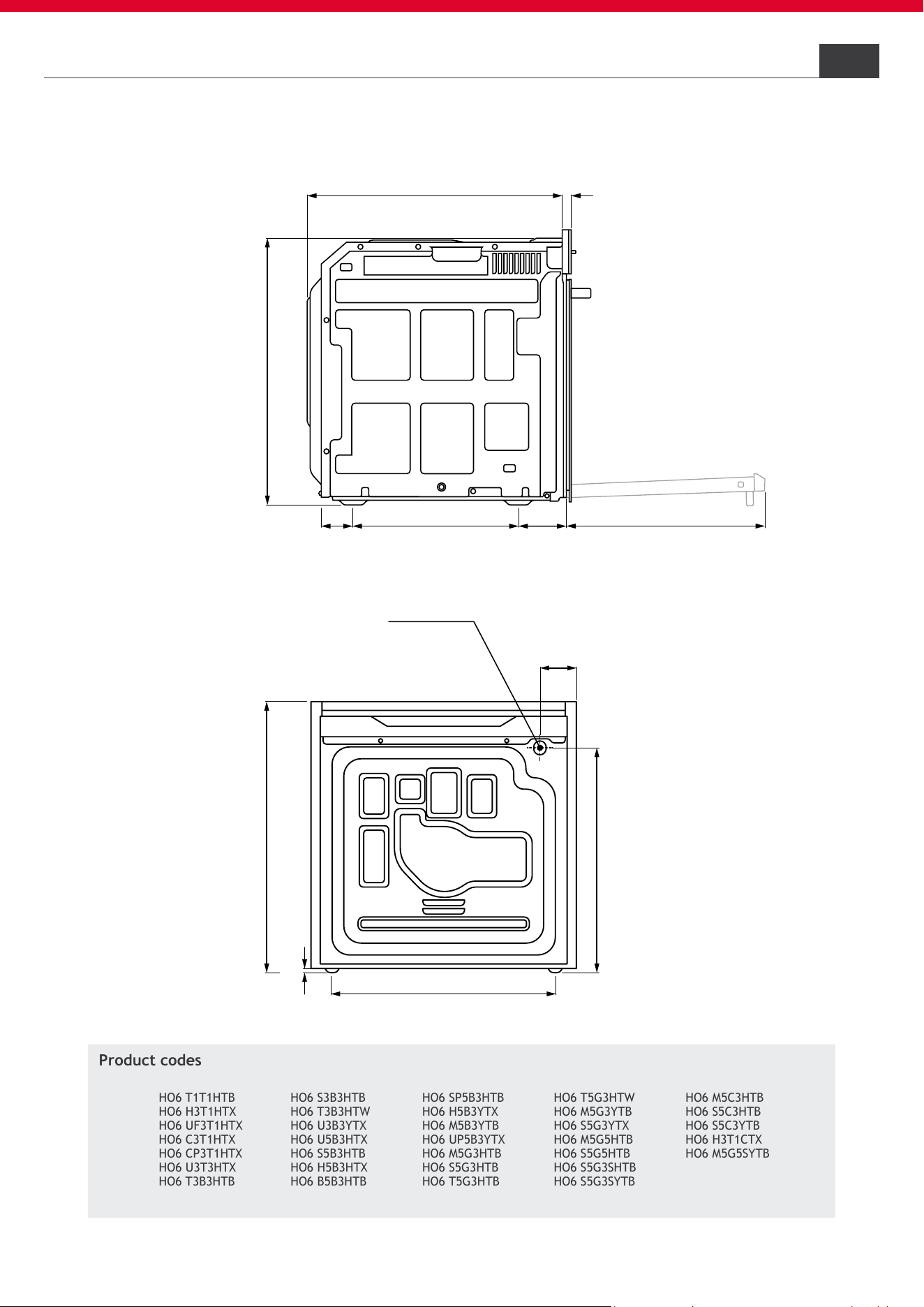
595
484,5
7,5
83
495
Cable 1100 mm
548
575
20
482
35599 114
5
HOOVER
Side view
Back view
Oven Dimensions
3
Dimensions in mm
Product codes
HO6 T1T1HTB
HO6 H3T1HTX
HO6 UF3T1HTX
HO6 C3T1HTX
HO6 CP3T1HTX
HO6 U3T3HTX
HO6 T3B3HTB
HO6 S3B3HTB
HO6 T3B3HTW
HO6 U3B3YTX
HO6 U5B3HTX
HO6 S5B3HTB
HO6 H5B3HTX
HO6 B5B3HTB
HO6 SP5B3HTB
HO6 H5B3YTX
HO6 M5B3YTB
HO6 UP5B3YTX
HO6 M5G3HTB
HO6 S5G3HTB
HO6 T5G3HTB
HO6 T5G3HTW
HO6 M5G3YTB
HO6 S5G3YTX
HO6 M5G5HTB
HO6 S5G5HTB
HO6 S5G3SHTB
HO6 S5G3SYTB
HO6 M5C3HTB
HO6 S5C3HTB
HO6 S5C3YTB
HO6 H3T1CTX
HO6 M5G5SYTB

4
3
5
3
3
4
5
4
5
5
5
5
5
6
5
2
0
1
7
6
5
9
5
4
5
5
1
00
3
61
Cable 1200 mm
6
HOOVER
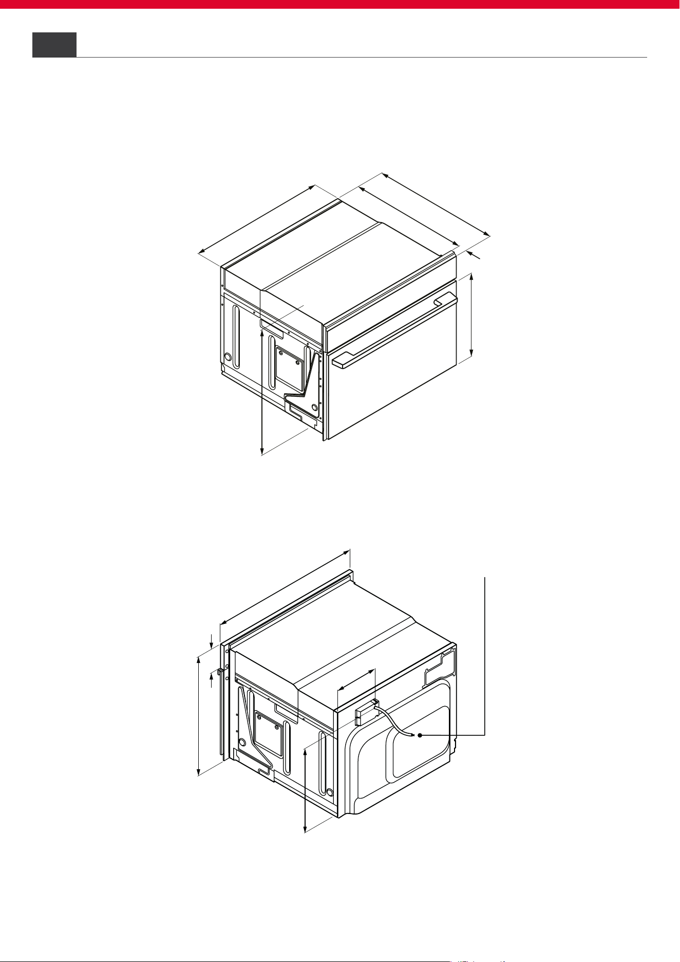
Compact oven h45 drop down opening4.1
4 Dimensions of combinable products
Frontal axonometric view
Back axonometric view
Dimensions in mm
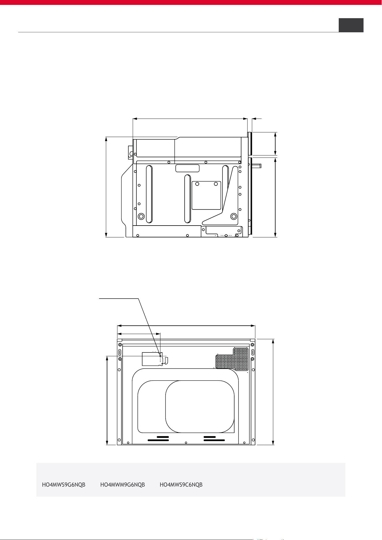
455
361
595
176
545
435
334
100
20
Cable 1200 mm
7
HOOVER
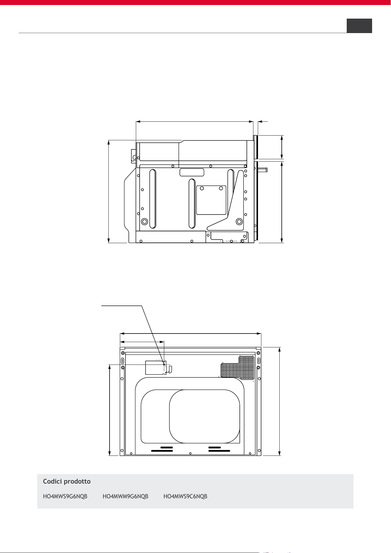
4.1 Compact oven h45 drop down opening
Side view
Back view
Dimensions in mm
Dimensions of combinable products
4
HO4MWS9G6NQB HO4MWM9G6NQB
HO4MWS9C6NQB
Product codes
Cable 1300 mm
8
HOOVER
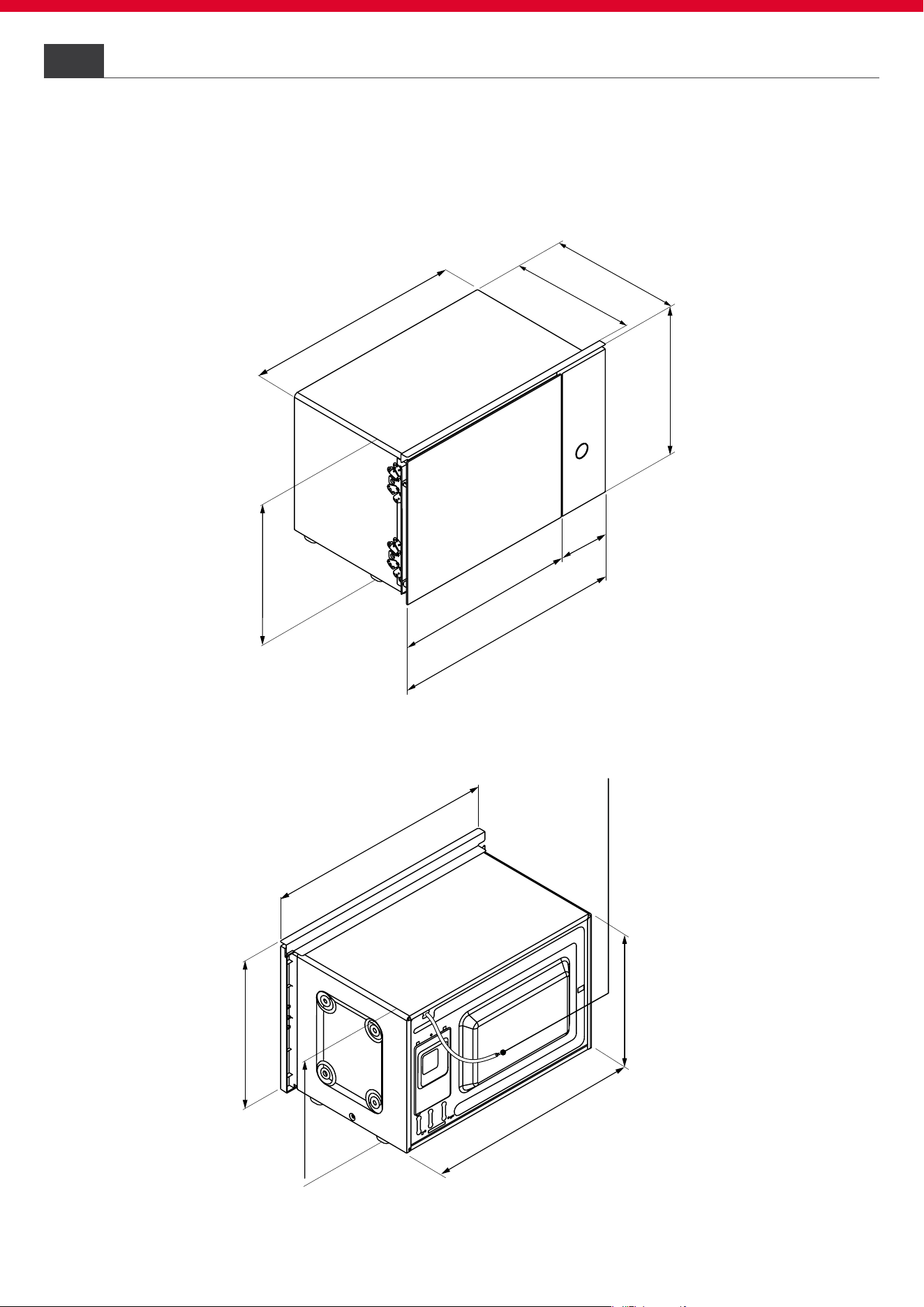
Compact oven h38 side wing opening4.2
4 Dimensions of combinable products
387
463
132
595
558
360
23
367
390
360
595
387
360
558
Frontal axonometric view
Back axonometric view
Dimensions in mm
Cable 1300 mm
9
HOOVER
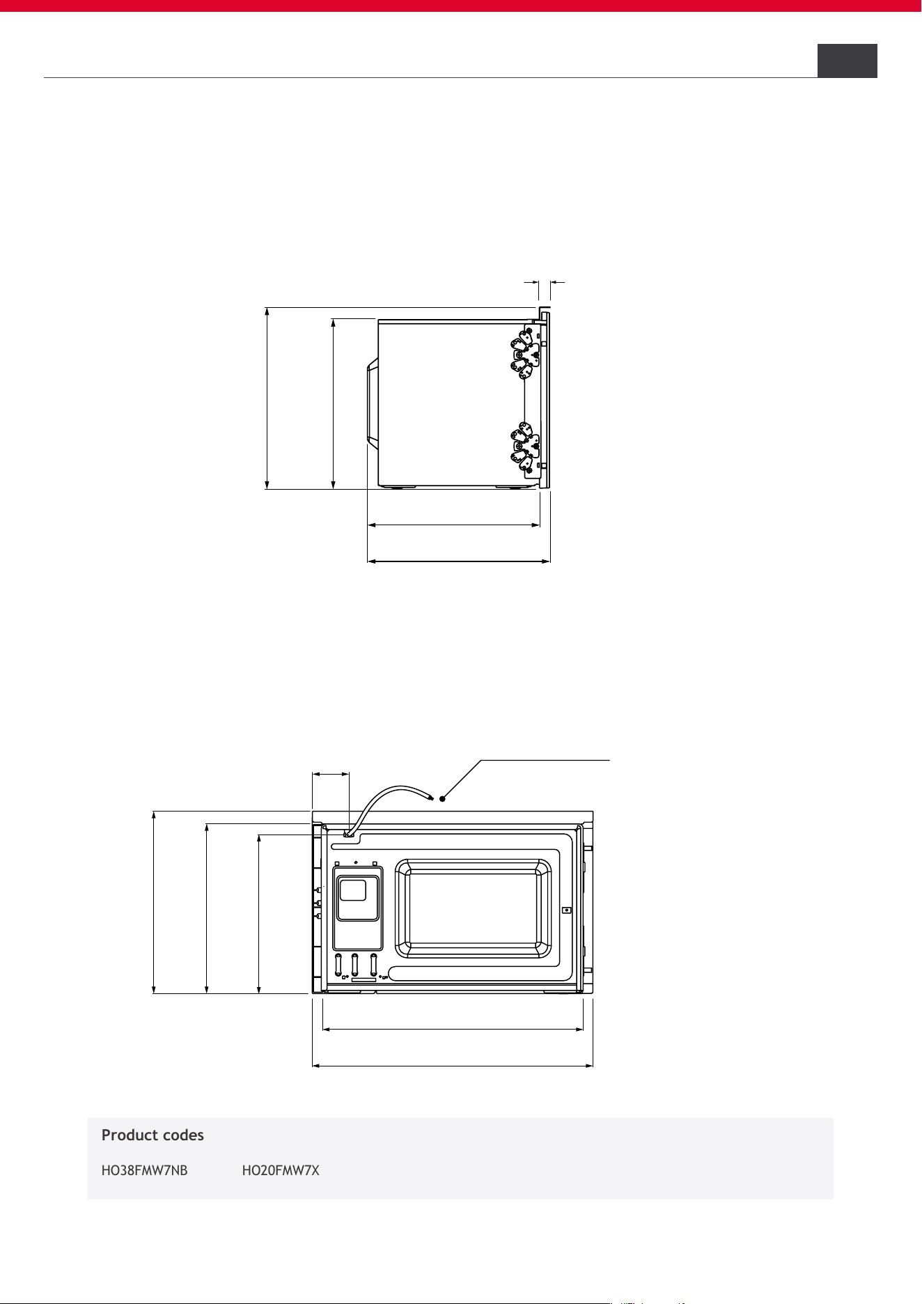
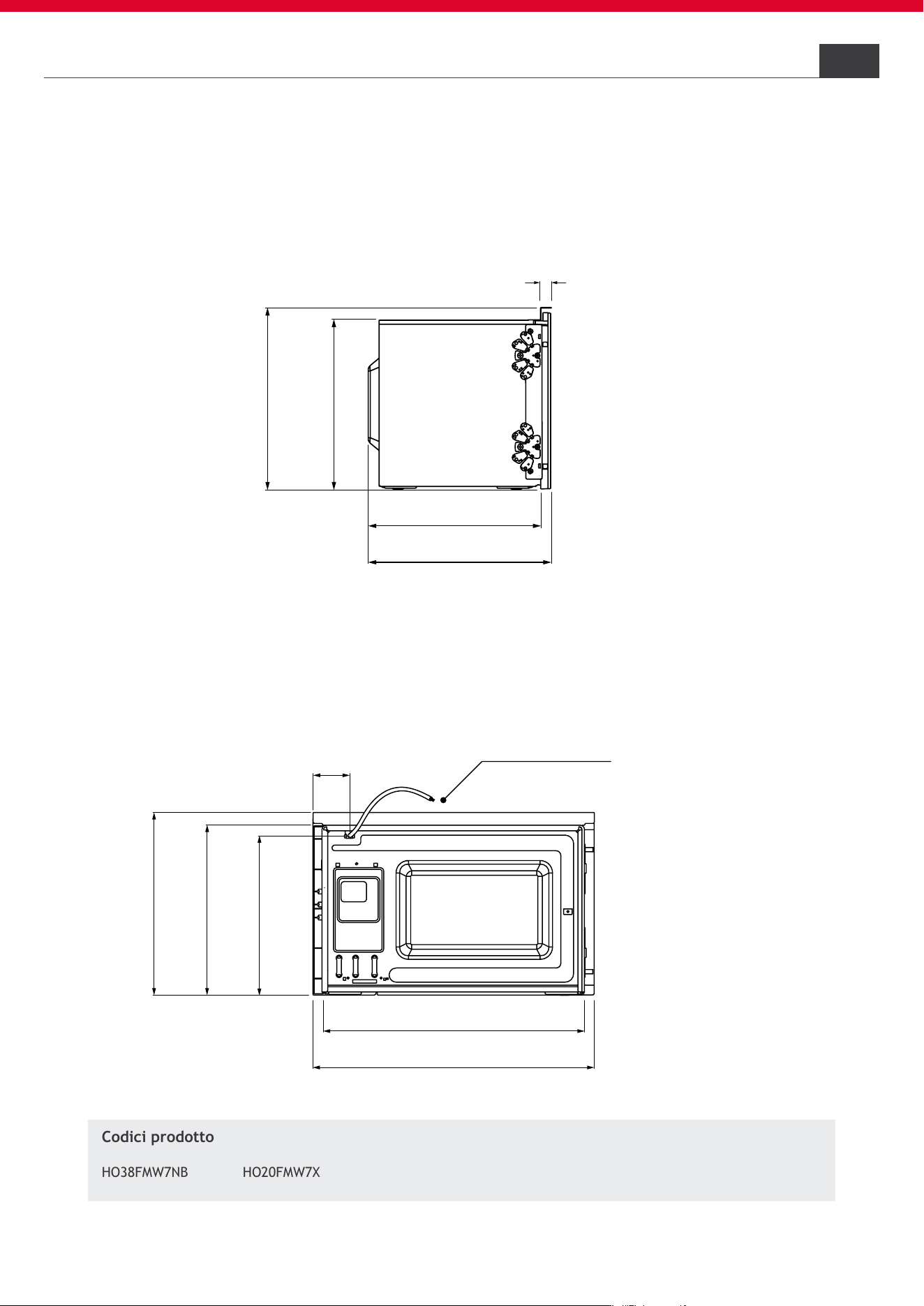
4.2 Compact oven h38 side wing opening
Dimensions of combinable products
4
387
360
390
367
23
595
558
78
387
360
329
Side view
Back view
Dimensions in mm
Product codes
HO38FMW7NB HO20FMW7X

19
530
549
541
142
139
595
40
134
Cable 930 mm
10
HOOVER
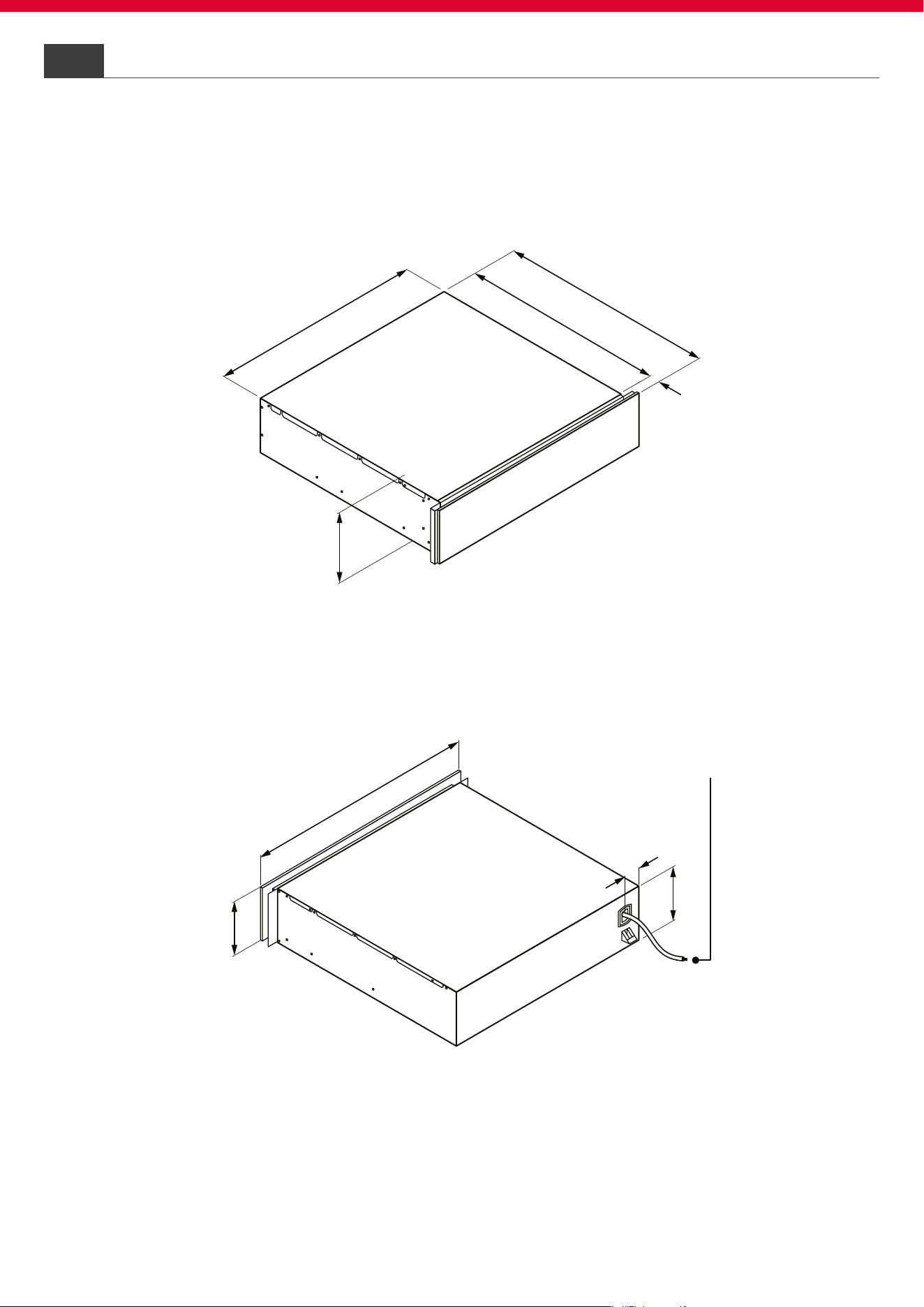
Warming drawer
4.3
4
Dimensions of combinable products
Frontal axonometric view
Back axonometric view
Dimensions in mm

530 19
142
595
139
176
Cable 930 mm
11
HOOVER
Warming drawer
4.3
139
Product codes
4
Dimensions of combinable products
Side view
Back view
Dimensions in mm
HOWD14C5SE HOWD14C5ME
m
i
n
.
45
A
5
60
+8
min
.
560
600
A
No connections
in this area
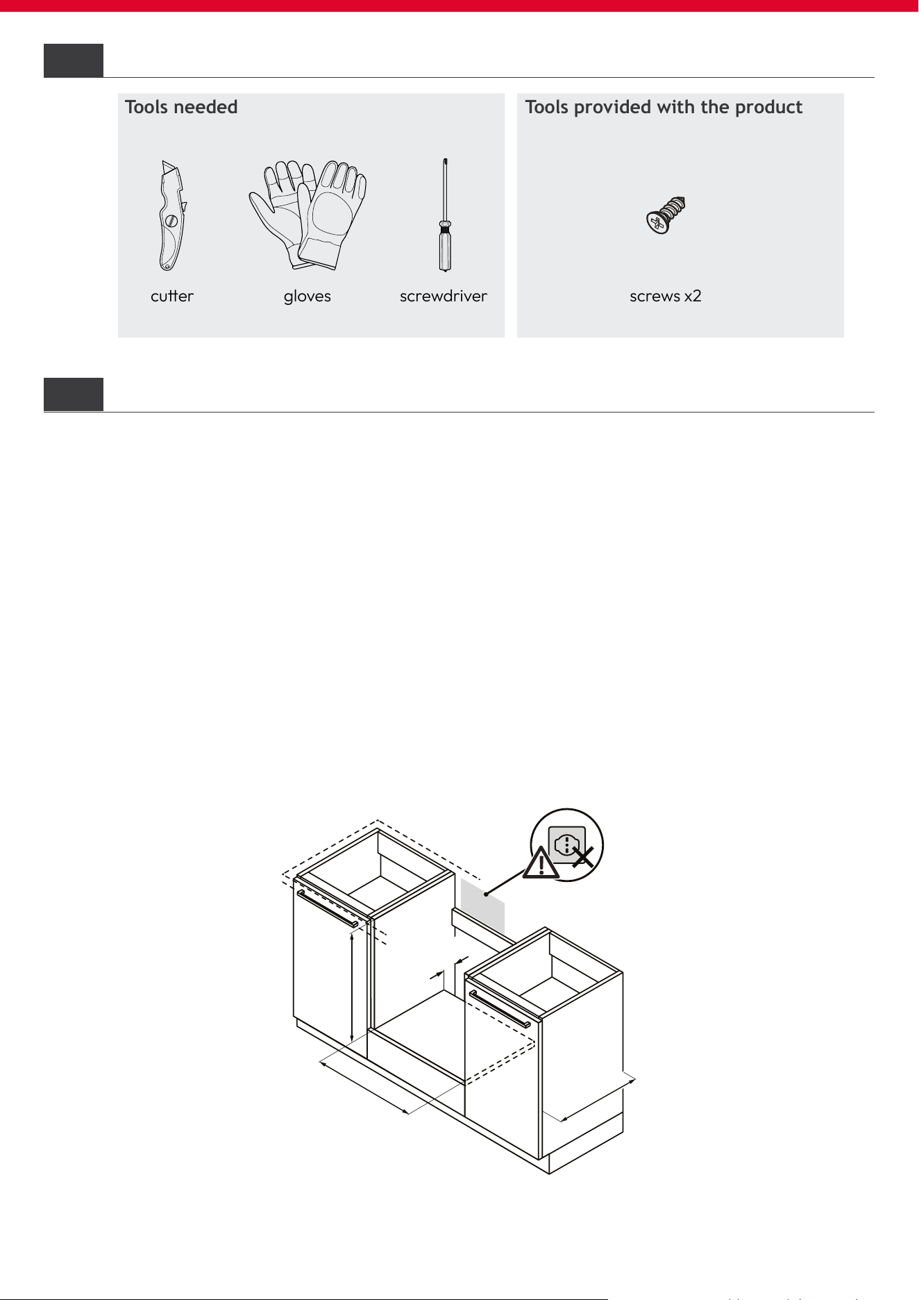
screws x2cuer gloves screwdriver
6.2
6.1
12
HOOVER
Installation tools
Tools provided with the productTools needed
Precautions
• Provide the recessed compartment without a back wall;
• Products protrude 20 mm from the cabinet edge;
• For ventilation of the product, follow the instructions in this manual;
• If the product is installed under a cooktop, also refer to the cooktop instal-
lation instructions;
• The connection socket must not be within area A;
• It is recommended that the cabinet be xed to the wall to prevent tipping over;
Furniture and ventilation
5
6
Undertop installation

X
X
X
X
min. 45 min. 45 min. 45
600
-2
600
-2
600
13
HOOVER
Corner installation
6.4
For corner installation, observe the dimensions and ush-installation in-
structions;
• In order to allow the opening of the door, take into account the minimum
dimensions of the corner mounting;
• The X measurement depends on the thickness of the cabinet front and
handle.
Furniture and ventilation
To ensure proper ventilation, also refer to the cooktop installation instructions;
Combination with cooktop
Base with oven in direct
contact with the top
Base with xing band
over the oven
Base with drawer
above the oven
6.3
6
560
+
8
min.
45
A
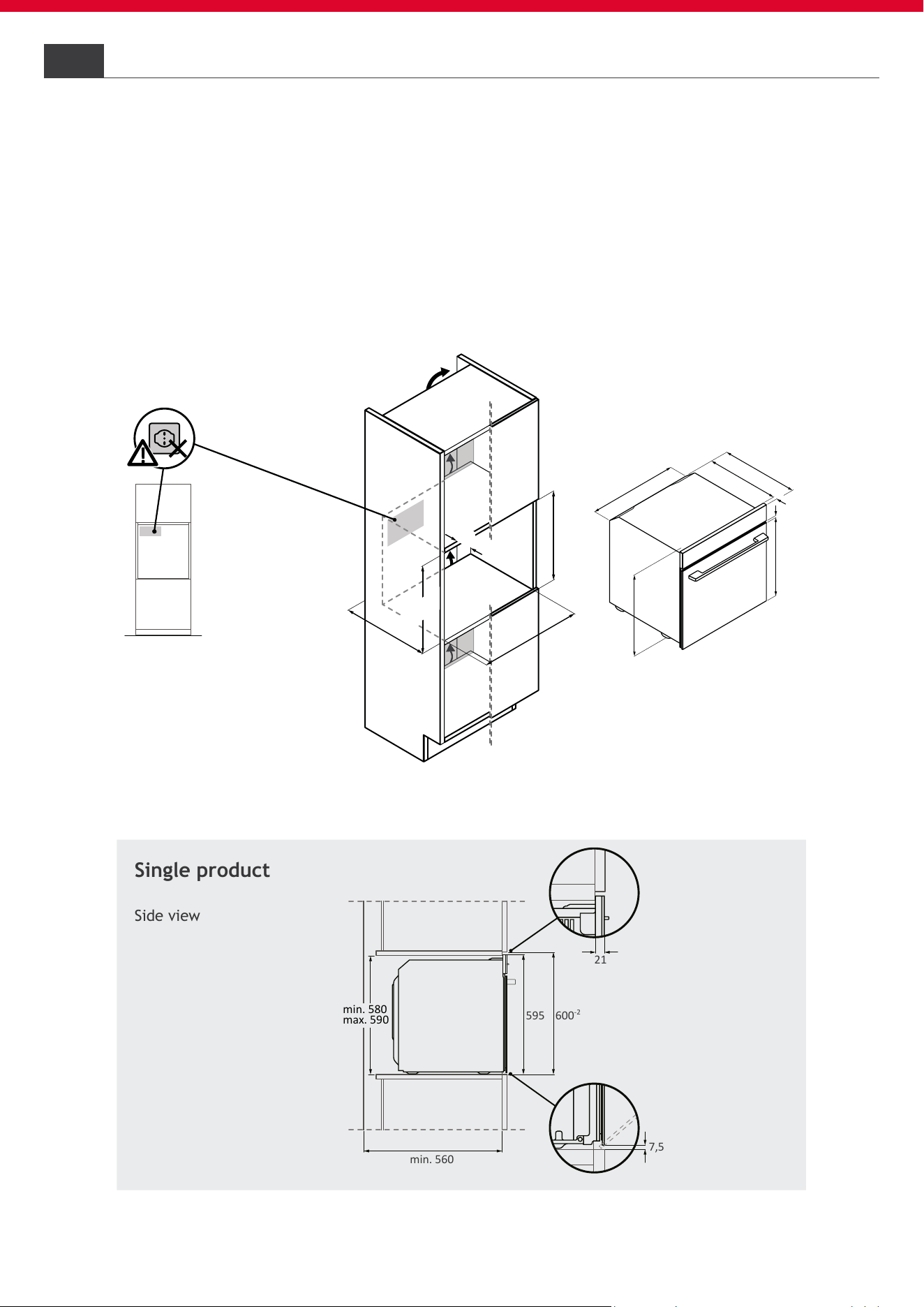
min. 580
max. 590
600
-2
min. 560
9
478,5
575
20
548
550
568
Single product
Side view
A
front view
A
No connecons
in this area
21
600
-2
595
min. 580
max. 590
min. 560
7,5
14
HOOVER
6
6.5
For column installation, observe the dimensions and ush-installation instructions;
• A rear slit is needed for ventilation of products;
• Pay attention that the air exchange is in accordance with the drawings below;
• Install products at a height where accessories can be easily picked up.
Installation oven in column
Furniture and ventilation
Single product
Side view
560
+
8
min.
45
A
445
460
-2
min. 560
43
5
3
34
545
555
565
20
A
front view
A
No connecons
in this area
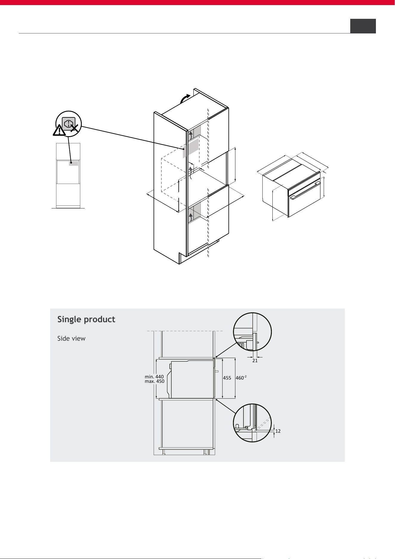
12
21
460
-2
455
min. 440
max. 450
15
HOOVER
6.6
Furniture and ventilation 6
Installation compact oven in column
A
A
560
+8
min.
45
min. 580
max. 590
600
-2
min. 560
435
334
5
4
5
5
5
5
56
5
20
19
530
5
49
541
142
A
A
front view
A
No connections
in this area
600
-2
142
455
min. 580
max. 590
16
HOOVER
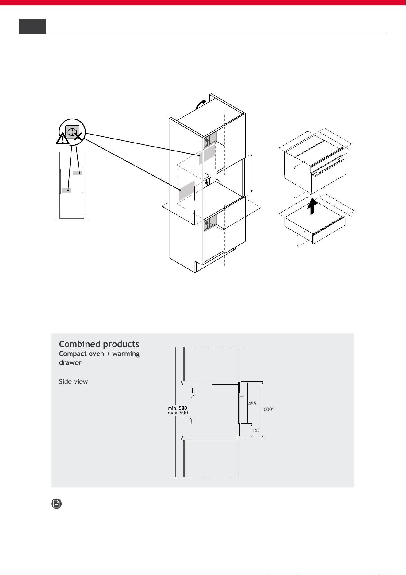
Installation compact oven + warming drawer in column
6.7
Combined products
Compact oven + warming
drawer
Side view
Note: The drawer front protrudes in height. Use caution during installation.
6 Furniture and ventilation

17
HOOVER
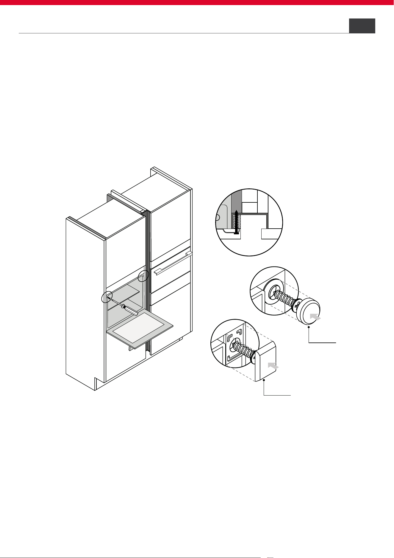
Drawer adjustments
Furniture and ventilation 6
6.8
Pannello frontale
A
B
A
Installation in combination with another appliance: make sure the warming
drawer is aligned with the matching appliance.
• To adjust the depth of the warming drawer, loosen screws “A” and adjust
brackets “B” until the front panel is properly aligned with the matching
appliance;
• Retighten screws “A” until fully secured.
• The angle of the front panel can be adjusted after loosening screws “A”.
When the panel is parallel to the cabinet and the front of the matching
appliance, tighten screws “A” again until fully secured.
18
HOOVER
A
A
min. 1056
min.440
max.450
min. 560
min.5 80
max.590
560
+8
min.
45
435
334
545
555
565
20
9
4
7
8
,5
5
7
5
20
548
5
50
568
A
No connections
in this area
front view
A
A
455
595
min. 440
max. 450
min. 580
max. 590
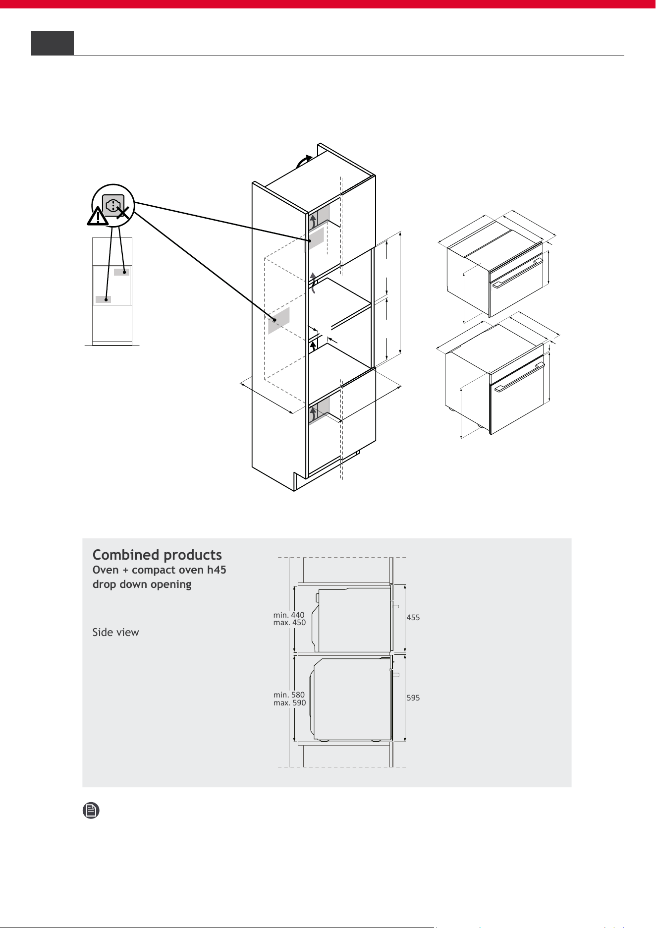
Installation oven + compact oven h45 in column
6.9
6 Furniture and ventilation
Note: to reduce the gap between machines, we suggest using shims to
raise the kiln a few millimeters.
Combined products
Oven + compact oven h45
drop down opening
Side view
Compac oven drop down opening
19
HOOVER
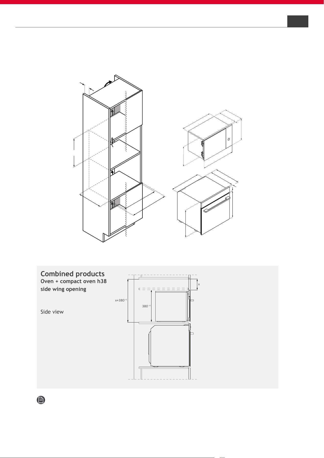
Note: to reduce the gap between machines, we suggest using shims to
raise the kiln a few millimeters.
Installation oven + compact oven h38 in column
6.10
Combined products
Oven + compact oven h38
side wing opening
Side view
Furniture and ventilation 6
Compac oven side wing opening
380
+3
x
x+380
+3
9
478,5
575
20
548
550
568
387
595
558
360
23
367
390
560
+8
600
min. 45
380
+2
min. 550

20
HOOVER
Connection to the mains
Safety warnings
7.1
7
To carry out the electrical connection of the device safely, observe the
following warnings:
• Any improperly performed repair, installation and maintenance can se-
riously endanger the user;
• The producer declares that it assumes no liability for direct or indirect
damage caused by incorrect installation, maintenance or repair. It is also
not liable for damage caused by missing or interrupted grounding pipeline
(electric shock);
• Have the oven connected to the power grid only by a qualied technician
who knows and complies with local regulations and additional regulations
of the local power company;
• The product falls under protection class I and can operate only if it is
equipped with a grounding conductor;
• The product must be voltage-free during installation;
• Connect the product using only the supplied cable;
• The product must be connected to a properly made electrical system;
• In case of incorrect installation, tampering with the device and improper
connection, the validity of the product warranty will expire;
• If the power cord is damaged, it should be replaced by the manufacturer,
a service technician or similarly qualied person to avoid risk. For any
repairs, contact customer service only and ask that original spare parts
be used;
• For any repairs, contact Customer Service exclusively and request the use
of original spare parts;
• Disconnect the product from the power supply before performing any
work or maintenance on it;
• To avoid electric shock, make sure the appliance is turned off before repla-
cing the bulb.
NOTE: Because the oven may need servicing, it is advisable to keep
another wall outlet available to plug the oven into if it is moved away from
the space where it is installed.
21
HOOVER
Instructions7.2
Power absorbed
See product data plate.
Differential circuit breaker (life-saving)
The use of a residual current circuit breaker (earth leakage circuit breaker)
with trip current complying with current standards is recommended.
Separation devices
In the event that it is necessary to use it, the oven must be connected to the
power supply via an omnipolar disconnection device that ensures a separa-
tion between contacts complying with overvoltage category III. Such a devi-
ce must withstand the maximum loads connected and comply with current
standards.
WARNING: To avoid any danger caused by accidentally resetting the ther-
mal cut-off device, the appliance must not be powered by an external swi-
tching device, such as a timer, or be connected to a circuit that is regularly
switched on and off. The product is not designed to be operated by an exter-
nal timer or a separate remote control system.
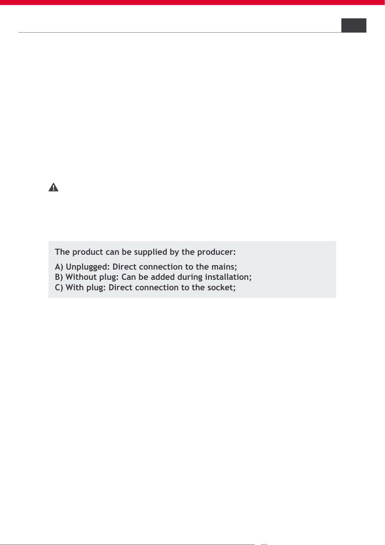
The product can be supplied by the producer:
A) Unplugged: Direct connection to the mains;
B) Without plug: Can be added during installation;
C) With plug: Direct connection to the socket;
A) Unplugged: Direct connection to the mains
The product is connected directly to the power supply by including an omni-
polar switch in the circuit;
The yellow-green ground wire must not be interrupted by the switch;
The omnipolar switch used for connection must be easily accessible when the
product is installed;
The connection to the power supply must be made taking into account the
polarity of the oven and the power source.
Connect the cables of the network connection respecting the color alloca-
tion:
• Green-yellow = ground;
• Blue = neutral;
• Brown = phase.
Connection to the mains 7

22
HOOVER
B) Without plug: Can be added during installation
NOTE: The appliance can only be connected to a grounded outlet instal-
led according to current standards. If you do not wish to add the plug, follow
step A.
If you want to add the plug:
• A plug suitable for the loads indicated on the product and complying with
current standards must be applied;
• Insert the plug into the grounded outlet. If the product is recessed, the
plug of the power cord must be freely accessible after installation. If free
access to the plug is not possible, an omnipolar separation device must be
installed in the xed electrical system in accordance with the installation
standards;
• The yellow-green ground wire must not be interrupted by the switch;
• The omnipolar switch used for connection must be easily accessible when
the product is installed.
C) With plug: Direct connection to the socket
The product can only be connected to a grounded outlet.
• Insert the plug into the grounded outlet. If the product is recessed, the
plug of the power cord must be freely accessible. If free access to the
plug is not possible, an omnipolar separation device must be installed in
the xed electrical system in accordance with the installation standards;
• The yellow-green ground wire must not be interrupted by the switch;
• The omnipolar switch used for connection must be easily accessible when
the equipment is installed;
• The socket must be suitable for the load indicated on the nameplate and
must have the ground contact connected and working;
• ln case of incompatibility between the socket and the plug of the applian-
ce, ask a qualied electrician to replace the socket with one of a suitable
type. The plug and socket must comply with the standards in force in the
country of installation;
• Should the product be supplied with a polarized plug, it should be con-
nected only to a polarized outlet.
Replacing the power cord
• Do not replace the cable yourself. Contact the authorized service center.
7 Connection to the mains

23
HOOVER
7.3
Other advice
The use of any household appliance requires adherence to certain basic rules:
• Do not pull the power cord to disconnect the appliance from the power
supply;
• Do not touch the appliance with wet or damp hands or feet;
• In general, the use of adapters, power strips or extension cords is discouraged;
• In case of malfunction and/or drop in performance, turn off the appliance
and do not tamper with it.
Connection to the mains 7

OR
24
HOOVER
• For safety reasons, the product should be used only when recessed;
• In order to properly work, the product needs a sufcient amount of fresh air
owing in;
• Make sure that the intermediate shelf on which the product rests does not
touch the wall;
• The surfaces in the recessed compartment are resistant to the tempera-
tures required by EN 60335;
• If installing the product below a cooktop, follow the instructions provided
by the cooktop manufacturer;
Instructions for oven installation
Important warnings
8
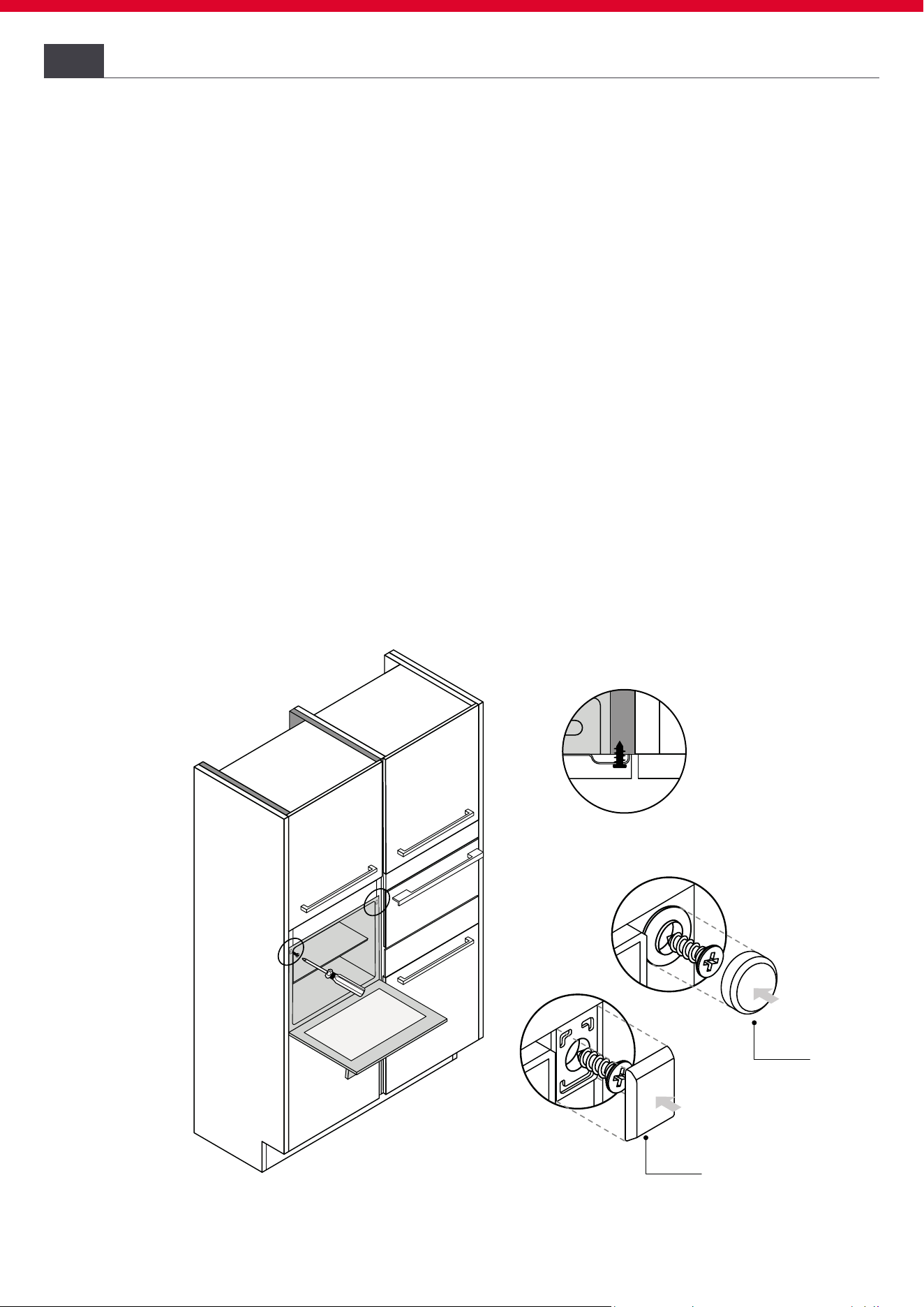
• Insert the product all the way in and center it;
• Secure the product with the screws;
• Cover the screws with the caps.
Fixing to the cabinet
8.1
8.2
Column with handle
caps
caps
tappini
tappini
OR
25
HOOVER
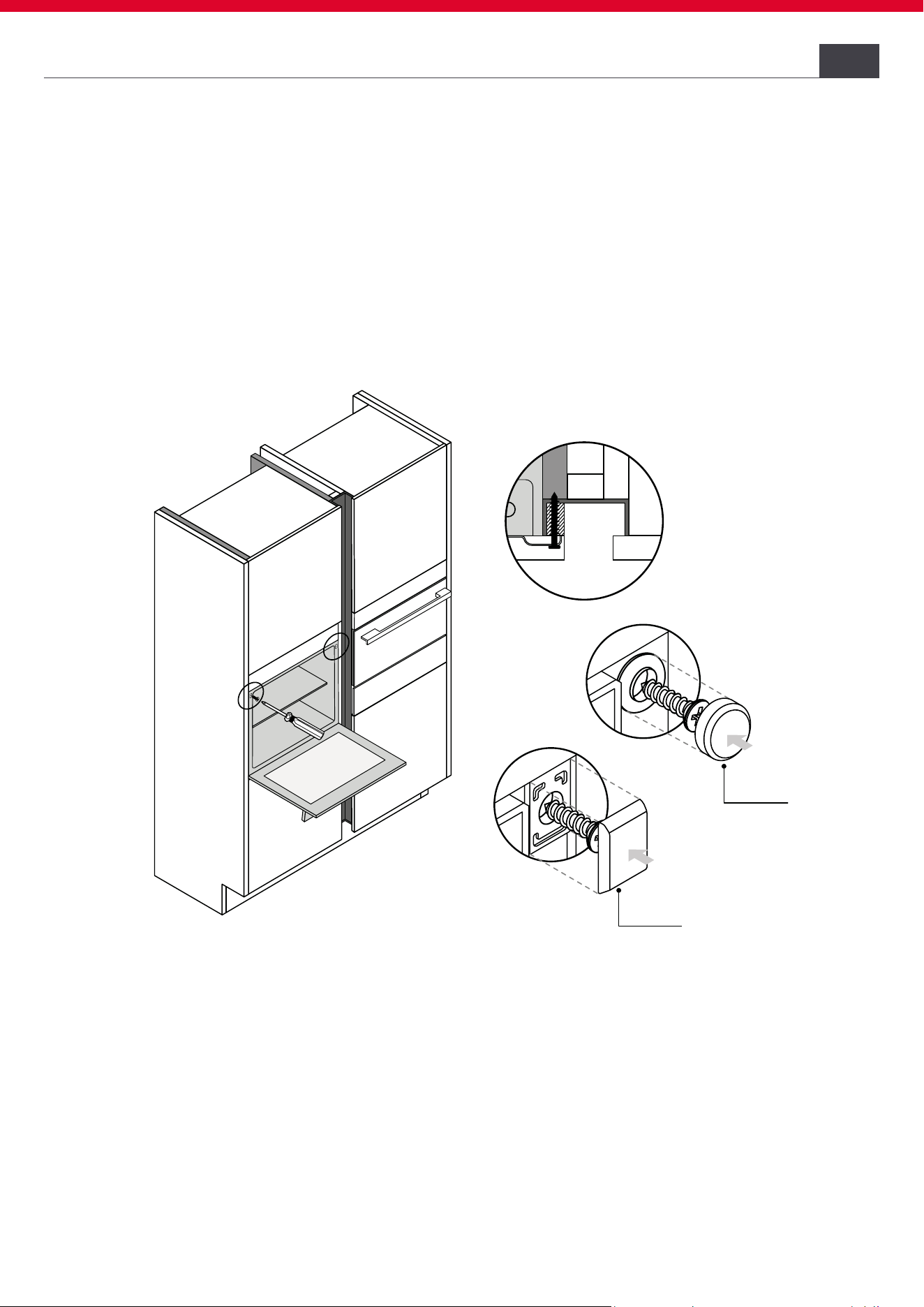
Instructions for oven installation
In case of kitchens with integrated verical handle (vertical groove):
• Apply a suitable piece of ller to cover any sharp edges and ensure secure
mounting;
• Pre-drill aluminum proles to make a screw tting;
• Secure the product with suitable screw (not provided);
8
Column with aluminum prole

27
HOOVER
2
Remove the packaging using a box cutter, making sure not to damage the product;
3
Remove all accessories in the oven and close the door again;
Instructions for Oven installation
8

28
HOOVER
4
Position the product close to the cabinet for recessing. After consulting the
installation manual, proceed with the electrical connections;
5
Lift the product by the side handles using gloves. Do not lift by door handle;
Instructions for oven installation8

29
HOOVER
6
Insert the product into the recessed compartment;
7
Open the door to secure the product to the cabinet. Screw the product to the
top ends; cover the screws with the caps provided.
Instructions for Oven installation
8
30
HOOVER
Disassembling the product11
• Disconnect the product from the power supply;
• Unscrew the xing screws;
• Lift the product slightly and pull it out completely;
• This product will not damage the cabinet, which can also be used with a
new appliance.
First startup10
When the product is preheated for the rst time, slight odors and smoke may
form when the door is opened. When the product is turned on for the rst
time, the following settings can be made, if available:
• Set time;
• Select the language;
• Set brightness and volume;
• Set amperage;
• For more information, see the product’s user manual.
Delivery to the user9
At the end of installation:
• Inform the user about essential functions;
• Inform the user about all aspects relevant to safe use and handling;
• Deliver accessories and instructions for use and assembly to the user to
be kept with care.
After installation is complete, remove the protective lm, tape, and all other
packing materials and remove the supplied accessories from inside the oven.
WARNING: The product requires adequate ventilation for normal opera-
tion. Do not obstruct the ventilation openings for any reason.
NOTE: The actual appearance of the oven depends on the model chosen.

31
HOOVER

BENVENUTI
Questo manuale di installazione è pensato per i produttori delle cucine che
accoglieranno questi prodotti. Per garantire la sicurezza e ottenere i miglio-
ri risultati, leggere attentamente questo manuale, comprese le istruzioni
di sicurezza, e conservarlo per riferimenti futuri. Prima di procedere con
l’installazione, prendere nota del numero di serie, in quanto potrebbe es-
sere necessario in caso di riparazioni. Vericare eventuali danni durante il
trasporto e consultare un tecnico in caso di dubbi prima dell’utilizzo. Tenere
sempre tutto il materiale da imballaggio a distanza di sicurezza dai bambini.
NOTA: Le caratteristiche, le immagini contenute nel manuale e gli acces-
sori del prodotto possono variare a seconda del modello acquistato.
i
1
HOOVER
Indice
1 Avvisi di sicurezza per l’installazione p.2-3
2 Dove posizionare il prodotto p.3
3 Dimensioni forno p.4-5
4 Dimensioni prodotti combinabili p.6-11
4.1 Compatto h45 apertura drop down
4.2 Compatto h38 apertura side wing
4.3 Cassetto
5 Strumenti per l’installazione p.12
6 Mobili e ventilazione p.12 - 19
6.1 Precauzioni
6.2 Installazione sottotop
6.3 Combinazione con piano cottura
6.4 Installazione ad angolo
6.5 Installazione forno in colonna
6.6 Installazione compatto in colonna
6.7 Installazione compatto + cassetto in colonna
6.8 Regolazioni del cassetto
6.9 Installazione forno + compatto h45 in colonna
6.10 Installazione forno + compatto h38 in colonna
7 Connessione alla rete elettrica p.20 - 23
7.1 Avvisi di sicurezza
7.2 Istruzioni
7.3 Altri consigli
8 Indicazioni relative all’installazione del orno p.24 - 29
8.1 Avvertenze importanti
8.2 Fissaggio al mobile
8.3 Installazione step by step
9 Consegna all’utente p.30
10 Prima messa in funzione p.30
11 Smontaggio del prodotto p.30

2
HOOVER
Avvisi di sicurezza per l’installazione
Osservare le presenti indicazioni prima di iniziare l’installazione del prodotto.
• La vostra sicurezza è molto importante per noi. Leggere attentamente que-
ste informazioni prima di utilizzare il forno;
• L’installazione deve essere effettuata da un tecnico qualicato che deve co-
noscere e rispettare le leggi vigenti nel paese di installazione e le istruzioni
del fabbricante;
• Se è richiesta l’assistenza del produttore per eliminare guasti derivanti da
un’errata installazione, tale assistenza non è coperta dalla garanzia;
• Rimuovere il materiale di imballaggio prima di mettere in funzione l’elettro-
domestico;
• Dopo aver disimballato il prodotto vericare che non sia danneggiato e, in
caso di problemi, contattare il centro assistenza, prima di procedere con
l’installazione e non collegarlo alla rete elettrica;
• Un prodotto danneggiato può essere la causa di un corto circuito, una scossa
elettrica, un principio d’incendio e altri pericoli;
• Vericare se nell’imballo ci sono accessori o materiali di corredo (buste con
viti, documenti, opuscoli etc.) e, nel caso, rimuoverli e conservarli;
• Il prodotto può essere posizionato in alto, in colonna, o sotto un piano di
lavoro;
• Prima di ssare l’elettrodomestico, accertarsi che la ventilazione sia suf-
ciente per consentire la corretta circolazione dell’aria fresca necessaria per
il raffreddamento e la salvaguardia dei componenti interni. In base al tipo
di sistemazione, praticare le aperture specicate sulle illustrazioni. Fissare
sempre il forno al mobile con le viti in dotazione con l’elettrodomestico;
• Il funzionamento dell’elettrodomestico alle frequenze nominali non richiede
interventi o installazioni supplementari;
• Il prodotto non deve essere installato dietro una porta decorativa per evitare
il surriscaldamento;
• Se occorre l’assistenza del fabbricante per eliminare eventuali guasti dovuti
all’installazione errata, tale assistenza non è coperta dalla garanzia. Atte-
nersi alle istruzioni per l’installazione fornite per il personale qualicato;
• Un’errata installazione può causare danni o lesioni a persone, animali o cose.
Il produttore non può essere ritenuto responsabile per tali danni o lesioni;
• L’utilizzo sicuro viene garantito solo se l’installazione è stata effettuata in
modo corretto secondo le presenti istruzioni. In caso di danni dovuti a un
montaggio scorretto la responsabilità ricade su chi ha installato il prodotto;
• Durante l’installazione, l’elettrodomestico non deve essere collegato alla
rete elettrica;
1

3
HOOVER
Dove installare il prodotto
• Durante le fasi di installazione, non utilizzare la maniglia dello sportello per
sollevare e trasportare il prodotto;
• Si consiglia di indossare guanti protettivi durante l’installazione per evitare
lesioni da taglio;
• I mobili da incasso e quelli adiacenti devono resistere a temperature pari a 95°C;
• La garanzia non copre danni causati da un’installazione errata;
• In caso di installazione errata, manomissione dell’apparecchio e collegamen-
to non conforme, decade la validità della garanzia del prodotto;
• Accertarsi che a incasso ultimato il cavo di alimentazione elettrica del pro-
dotto non sia accessibile;
• Dopo il montaggio, il cavo di alimentazione non deve entrare in contatto con
parti mobili dei componenti della cucina (ad esempio un cassetto) e non deve
essere esposto a sollecitazioni meccaniche;
• Questo prodotto richiede una costante ventilazione durante l’uso. Non copri-
re le prese d’aria;
• Nel consegnare il prodotto all’utente nale, il tecnico deve assicurarsi che
sia stato installato correttamente.
• Installare e utilizzare questo prodotto in un ambiente chiuso, coperto, asciut-
to e ben ventilato;
• Non installare il prodotto in ambienti aperti ed esposti agli agenti atmosferici;
• Questo prodotto è stato progettato per essere utilizzato no ad una altitudi-
ne massima di 2000 metri;
• Montare il prodotto in prossimità di una presa elettrica;
• Utilizzare il prodotto solo se inserito in un vano incasso, altrimenti si rischia-
no lesioni e scottature.
2

484,5
595
100
83
595
Cavo 1100 mm
355
99
114
60
4
HOOVER
Vista assonometrica
frontale
3
Vista assonometrica
posteriore
Dimensioni forno
Dimensioni in mm
9
478,5
575
20
548
550
568
570
565
60

595
484,5
7,5
83
Cavo 1100 mm
548
575
20
482
35599 114
495
5
HOOVER
Vista laterale
Vista posteriore
Dimensioni forno
3
HO6 T1T1HTB
HO6 H3T1HTX
HO6 UF3T1HTX
HO6 C3T1HTX
HO6 CP3T1HTX
HO6 U3T3HTX
HO6 T3B3HTB
HO6 S3B3HTB
HO6 T3B3HTW
HO6 U3B3YTX
HO6 U5B3HTX
HO6 S5B3HTB
HO6 H5B3HTX
HO6 B5B3HTB
HO6 SP5B3HTB
HO6 H5B3YTX
HO6 M5B3YTB
HO6 UP5B3YTX
HO6 M5G3HTB
HO6 S5G3HTB
HO6 T5G3HTB
HO6 T5G3HTW
HO6 M5G3YTB
HO6 S5G3YTX
HO6 M5G5HTB
HO6 S5G5HTB
HO6 S5G3SHTB
HO6 S5G3SYTB
HO6 M5C3HTB
HO6 S5C3HTB
HO6 S5C3YTB
HO6 H3T1CTX
HO6 M5G5SYTB
Dimensioni in mm
Codici prodotto
4
3
5
3
3
4
5
4
5
5
5
5
5
6
5
2
0
Cavo 1200 mm
1
7
6
5
9
5
4
5
5
1
00
3
61
6
HOOVER
Compatto h45 apertura drop down4.1
Vista assonometrica
frontale
Vista assonometrica
posteriore
4
Dimensioni prodotti combinabili
Dimensioni in mm
455
361
595
176
Cavo 1200 mm
545
435
334
100
20
7
HOOVER
4.1
Vista laterale
Vista posteriore
Dimensioni in mm
HO4MWS9G6NQB HO4MWM9G6NQB
HO4MWS9C6NQB
Compatto h45 apertura drop down
Codici prodotto
Dimensioni prodotti combinabili
4

8
HOOVER
Compatto h38 apertura side wing 4.2
4
Dimensioni prodotti combinabili
Cavo 1300 mm
387
463
132
595
558
360
23
367
390
360
595
387
360
558
Vista assonometrica
frontale
Vista assonometrica
posteriore
Dimensioni in mm
9
HOOVER
4.2 Compatto h38 apertura side wing
Dimensioni prodotti combinabili
4
387
360
390
367
23
Cavo 1300 mm
595
558
78
387
360
329
Vista laterale
Vista posteriore
Dimensioni in mm
Codici prodotto
HO38FMW7NB HO20FMW7X
19
530
549
541
142
139
Cavo 930mm
595
40
134
10
HOOVER
Cassetto4.3
Vista assonometrica
frontale
Vista assonometrica
posteriore
4
Dimensioni prodotti combinabili
Dimensioni in mm
530 19
142
595
139
Cavo 930 mm
176
11
HOOVER
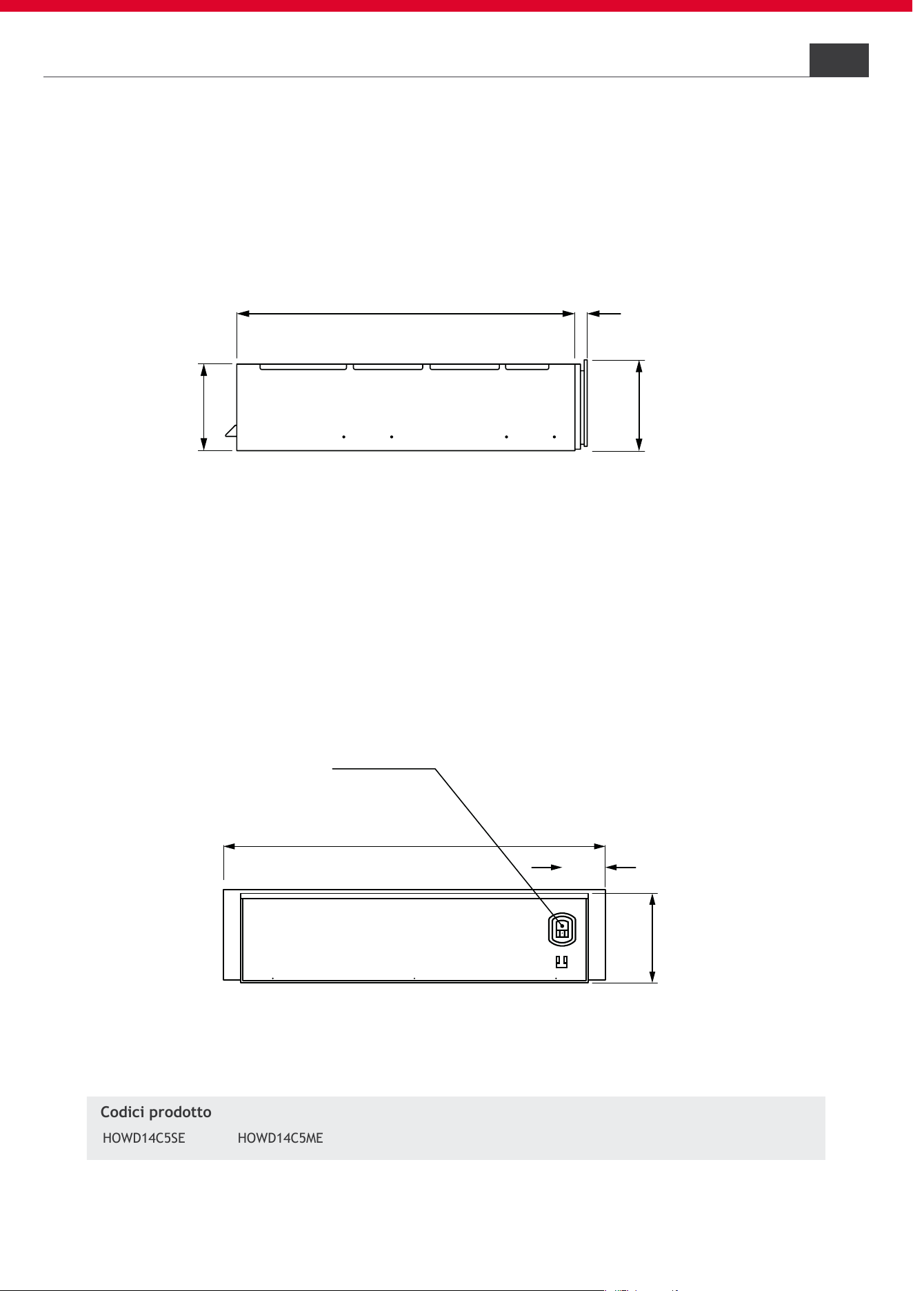
Cassetto
4.3
Vista laterale
Vista posteriore
139
HOWD14C5SE
Dimensioni in mm
HOWD14C5ME
Codici prodotto
Dimensioni prodotti combinabili
4
m
i
n
.
45
A
5
60
+8
min
.
560
600
A
Nessun allacciamento
in questa area
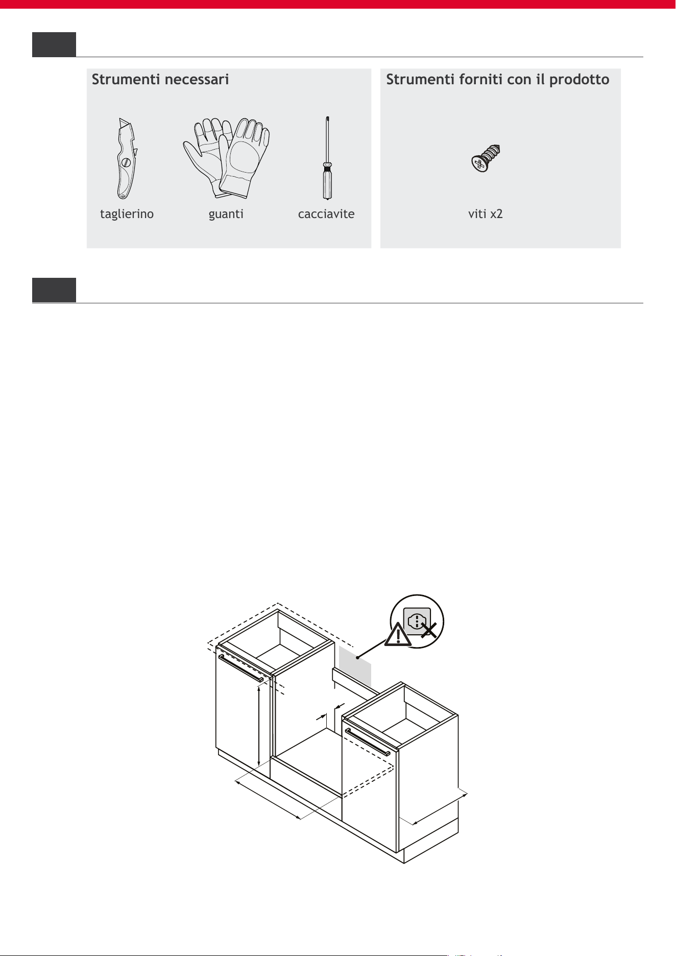
viti x2taglierino guanti cacciavite
6.2
6.1
12
HOOVER
Strumenti per l’installazione
Strumenti forniti con il prodottoStrumenti necessari
Precauzioni
• Prevedere il vano incasso senza parete posteriore;
• I prodotti sporgono di 20 mm rispetto alla battuta del mobile;
• Per la ventilazione del prodotto seguire le istruzioni riportate in questo
manuale;
• Se il prodotto viene installato sotto un piano cottura, consultare anche le
istruzioni di installazione del piano cottura;
• La presa di collegamento non deve trovarsi all’interno dell’area A;
• Si consiglia di ssare il mobile alla parete per evitare il ribaltamento.
Mobili e ventilazione
5
6
Installazione Sottotop
min. 45
600
-2
min. 45
600
min. 45
600
-2
X
X
X
X
13
HOOVER
Installazione ad angolo
6.4
Per l’installazione angolare, osservare le dimensioni e le indicazioni di incasso;
• Per consentire l’apertura dello sportello, tenere conto delle dimensioni
minime del montaggio angolare;
• La misura X dipende dallo spessore del frontale del mobile e della maniglia.
Mobili e ventilazione
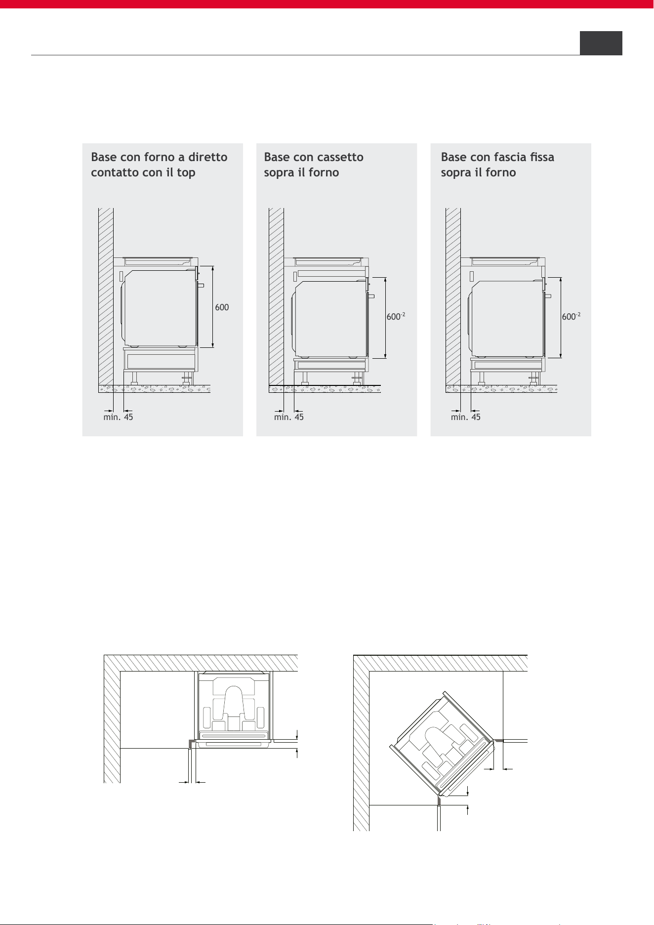
Per garantire la corretta ventilazione, consultare anche le istruzioni di installa-
zione del piano cottura.
Combinazione con piano cottura
Base con forno a diretto
contatto con il top
Base con fascia ssa
sopra il forno
Base con cassetto
sopra il forno
6.3
6
560
+
8
min.
45
A
min. 580
max. 590
600
-2
min. 560
9
478,5
575
20
548
550
568
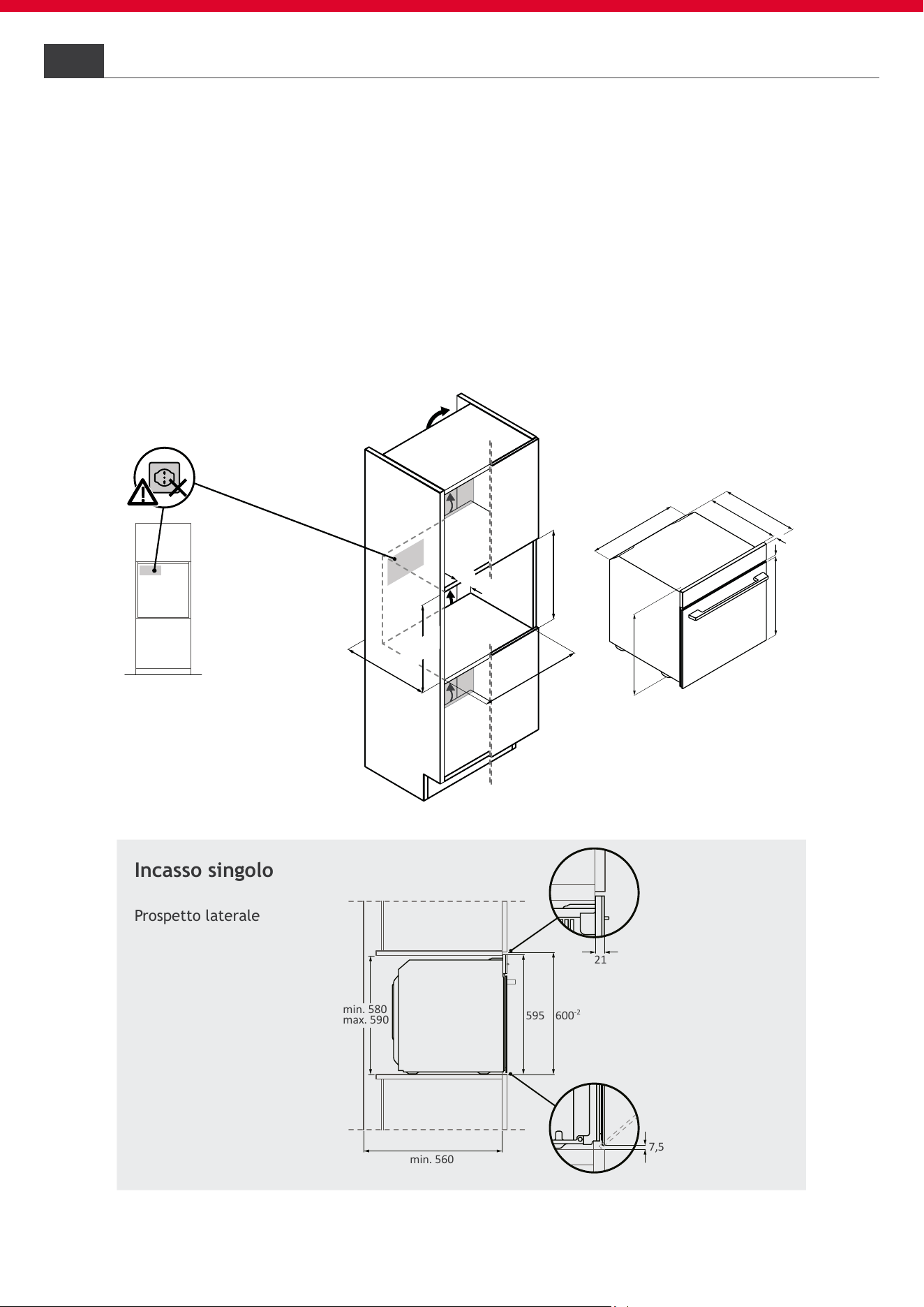
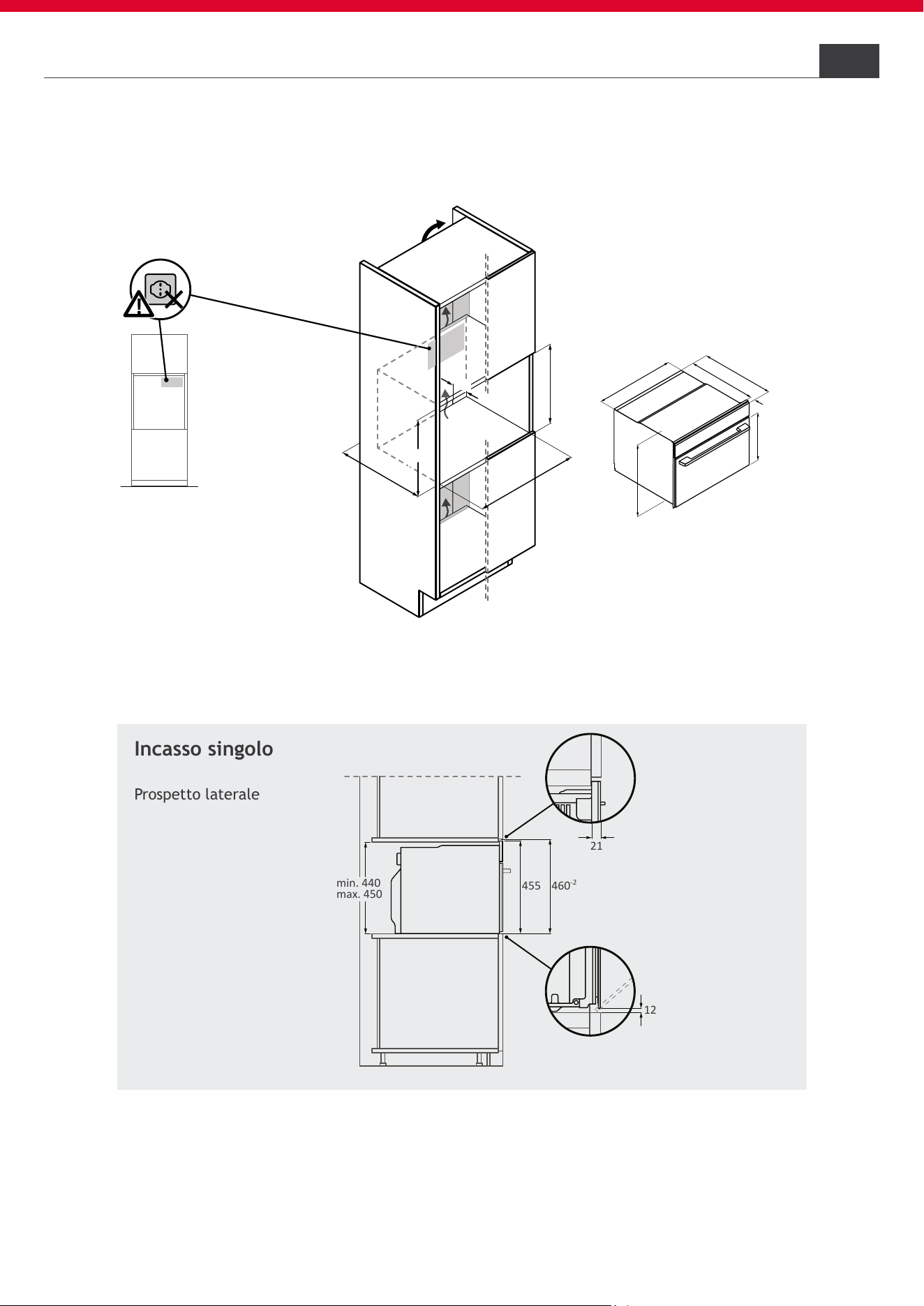
Incasso singolo
Prospetto laterale
A
vista frontale
A
Nessun allacciamento
in questa area
21
600
-2
595
min. 580
max. 590
min. 560
7,5
14
HOOVER
6
6.5
Per l’installazione in colonna, osservare le dimensioni e le indicazioni di incasso;
• Per la ventilazione dei prodotti occorre una fessura posteriore;
• Prestare attenzione a che lo scambio di aria sia conforme ai disegni di seguito;
• Installare i prodotti a un’altezza tale da poter prelevare gli accessori sen-
za problemi.
Installazione forno in colonna
Mobili e ventilazione
Incasso singolo
Prospetto laterale
560
+
8
min.
45
A
445
460
-2
min. 560
43
5
3
34
545
555
565
20
A
vista frontale
A
Nessun allacciamento
in questa area
12
21
460
-2
455
min. 440
max. 450
15
HOOVER
6.6
Mobili e ventilazione 6
Installazione compatto in colonna
6 Mobili e ventilazione
16
HOOVER
A
A
560
+8
min.
45
min. 580
max. 590
600
-2
m
in. 560
435
334
5
4
5
5
5
5
56
5
20
19
530
549
541
142
A
A
vista frontale
A
Nessun allacciamento
in questa area
600
-2
142
455
min. 580
max. 590
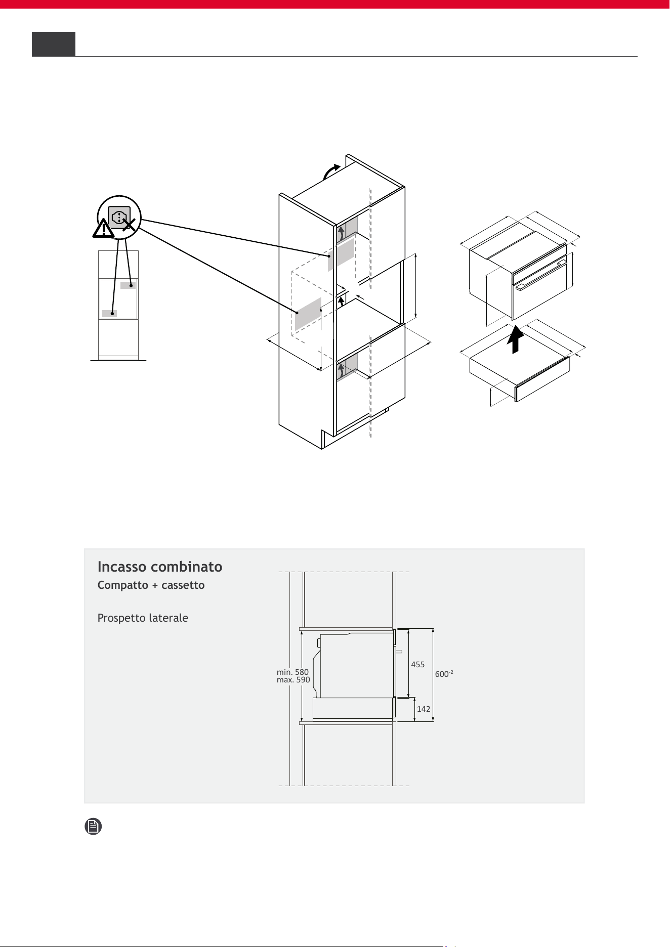
Installazione compatto + cassetto in colonna
6.7
Incasso combinato
Compatto + cassetto
Prospetto laterale
Nota: il frontale del cassetto sporge in altezza. Prestare attenzione
durante l’installazione.
6Mobili e ventilazione
17
HOOVER
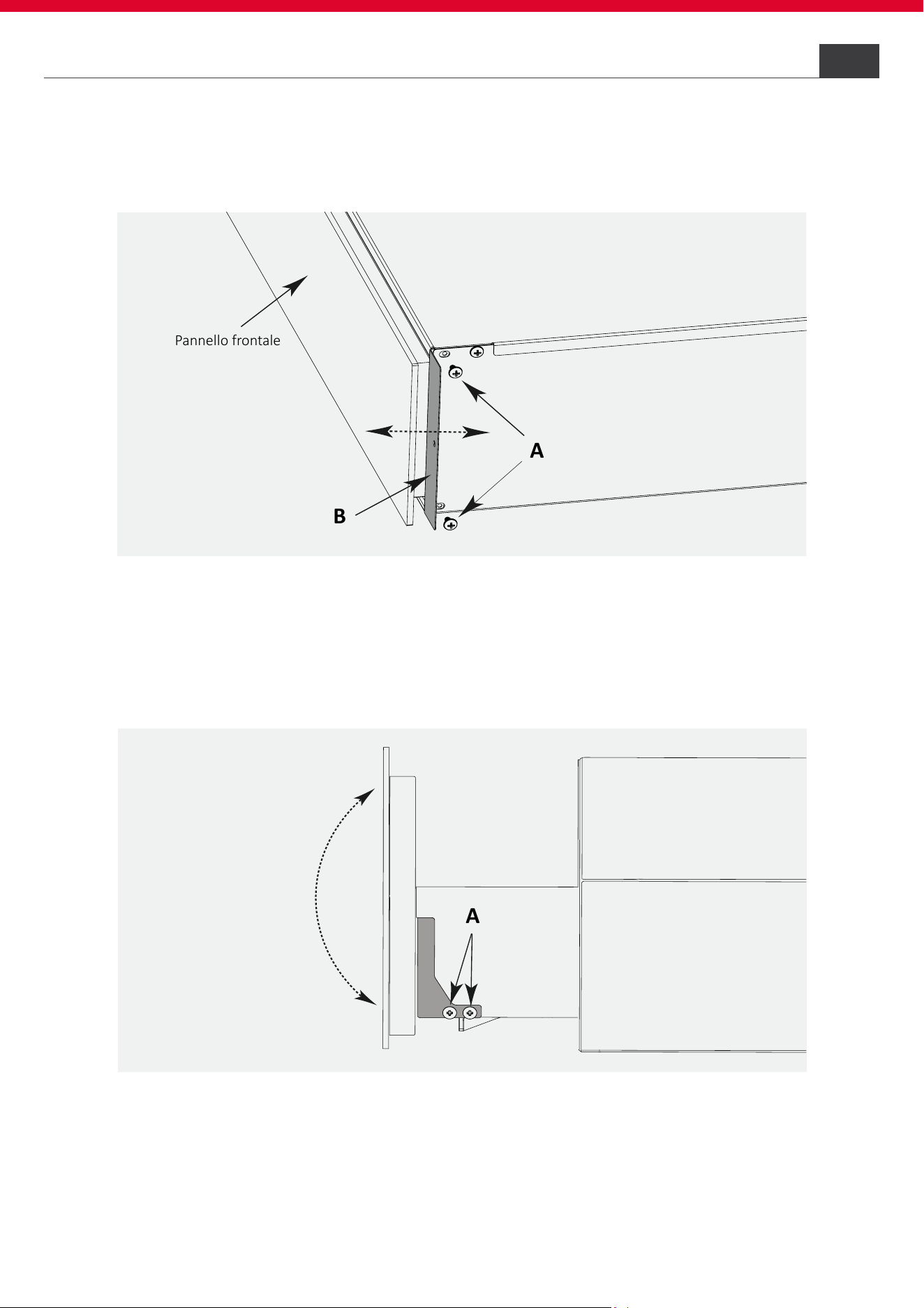
Regolazioni del cassetto
6.8
Installazione in abbinamento ad un altro elettrodomestico: vericare che il
cassetto sia allineato all’elettrodomestico in abbinamento.
Pannello frontale
A
B
A
• per regolare la profondità del cassetto scaldavivande, allentare le viti
“A” e regolare le squadrette “B” no al corretto allineamento del pannel-
lo frontale con l’elettrodomestico in abbinamento;
• Riavvitare le viti “A” no al completo ssaggio.
• L’inclinazione del pannello frontale può essere regolata dopo aver al-
lentato le viti “A”. Quando il pannello è parallelo al mobile e alla parte
frontale dell’elettrodomestico in abbinamento, riavvitare le viti “A” no
al completo ssaggio.
A
A
min. 1056
min.440
max.450
min. 560
min.5 80
max.590
560
+8
min.
45
435
334
545
555
565
20
9
4
7
8
,5
5
75
20
548
5
50
568
A
Nessun allacciamento
in questa area
vista frontale
A
A
455
595
min. 440
max. 450
min. 580
max. 590
18
HOOVER
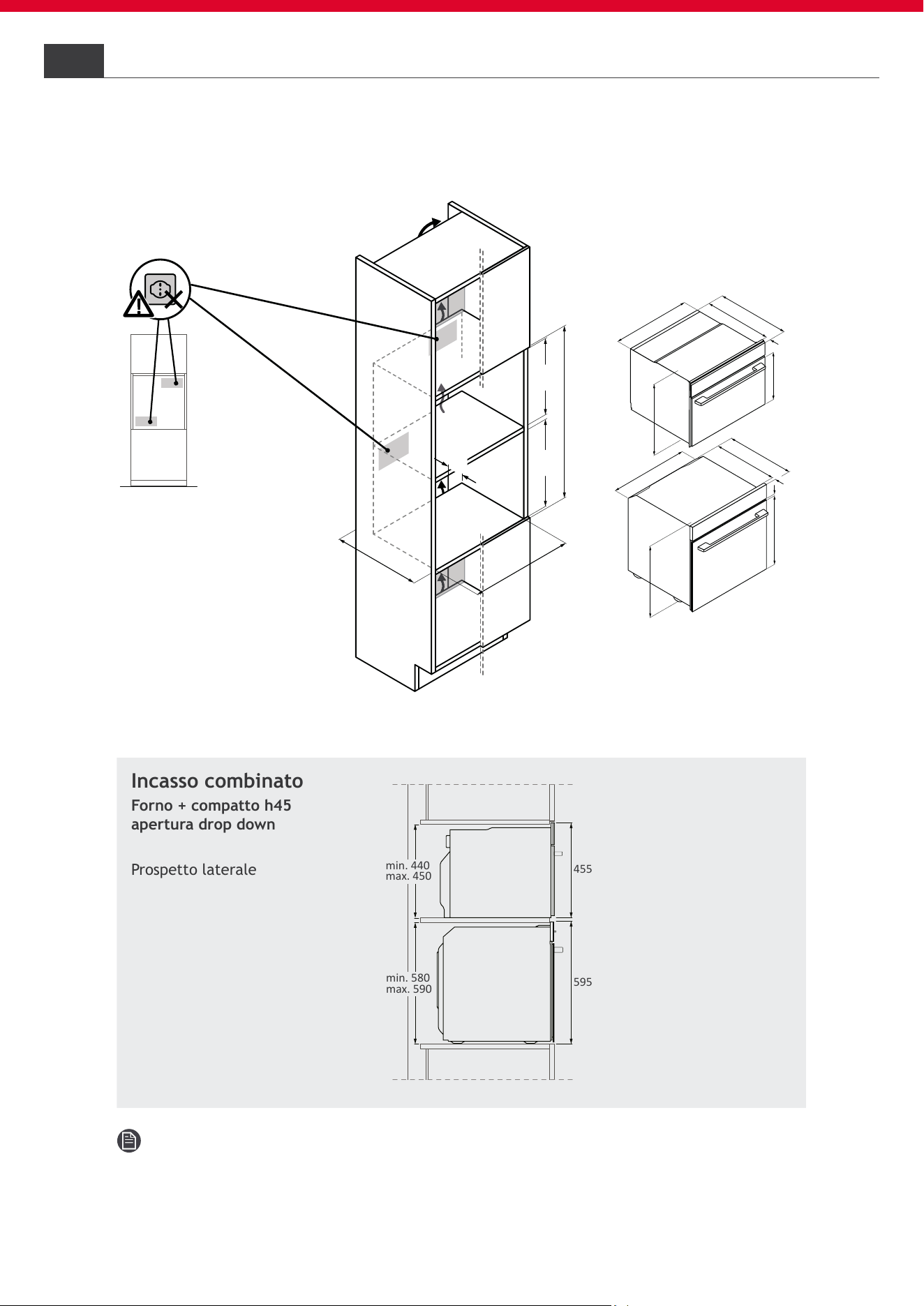
6 Mobili e ventilazione
Nota: per ridurre il gap tra le macchine, suggeriamo di utilizzare degli
spessori per sollevare il forno di alcuni millimetri.
Installazione forno + compatto h45 in colonna
6.9
Incasso combinato
Forno + compatto h45
apertura drop down
Prospetto laterale
19
HOOVER
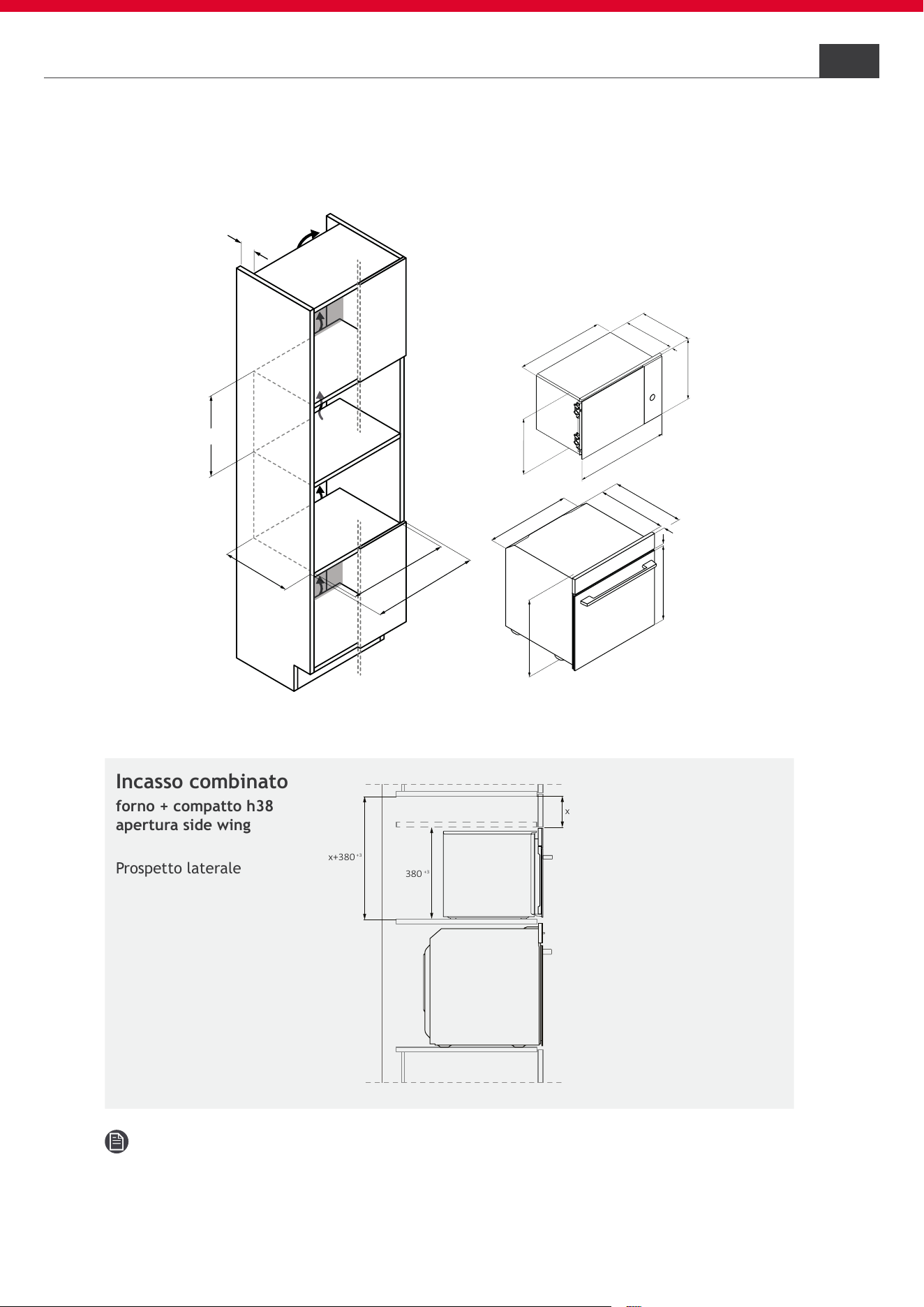
Nota: per ridurre il gap tra le macchine, suggeriamo di utilizzare degli
spessori per sollevare il forno di alcuni millimetri.
6Mobili e ventilazione
6.10
Installazione forno + compatto h38 in colonna
Incasso combinato
forno + compatto h38
apertura side wing
Prospetto laterale
380
+3
x
x+380
+3
9
478,5
575
20
548
550
568
387
595
558
360
23
367
390
560
+8
600
min. 45
380
+2
min. 550

20
HOOVER
Connessione alla rete elettrica
Avvisi di sicurezza
7.1
7
Per eseguire il collegamento elerico dell’apparecchio in sicurezza, osservare le
seguen avvertenze:
• Qualsiasi riparazione, installazione e manutenzione non eseguita corret-
tamente può mettere seriamente in pericolo l’utente;
• L’azienda produttrice dichiara di non assumersi alcuna responsabilità per
danni diretti o indiretti causati da errati interventi di installazione, ma-
nutenzione o riparazione. Non risponde inoltre dei danni causati dalla
mancanza o dall’interruzione della conduttura di messa a terra (es. scos-
sa elettrica);
• Far allacciare il forno alla rete elettrica solo da un tecnico qualicato che
conosca e rispetti le normative locali e le normative aggiuntive dell’a-
zienda elettrica locale;
• Il prodotto rientra nella classe di protezione I e può funzionare solo se
dotato di un conduttore di terra;
• Il prodotto deve essere privo di tensione durante l’installazione;
• Allacciare il prodotto esclusivamente mediante il cavo fornito in dotazione;
• Il prodotto dev’essere allacciato ad un impianto elettrico realizzato a
regola d’arte;
• In caso di danni causati da un allacciamento non corretto, decade la va-
lidità della garanzia;
• Se il cavo di alimentazione è danneggiato, deve essere sostituito dal pro-
duttore, da un tecnico dell’assistenza o da una persona con analoga quali-
ca per evitare rischi. Per eventuali riparazioni, rivolgersi esclusivamente
all’assistenza clienti e chiedere che vengano utilizzati ricambi originali;
• Per eventuali riparazioni rivolgersi esclusivamente al Servizio Assistenza
Clienti e richiedere l’utilizzo di ricambi originali;
• Scollegare il prodotto dalla rete elettrica prima di effettuare qualsiasi
intervento o manutenzione sullo stesso;
• Per evitare scosse elettriche, accertarsi che l’elettrodomestico sia spento
prima di sostituire la lampadina.
NOTA: poiché il forno potrebbe necessitare di interventi di manutenzio-
ne, si consiglia di tenere a disposizione un’altra presa a muro a cui poter
collegare il forno a questa qualora venga allontanato dallo spazio in cui è
installato.
21
HOOVER
Istruzioni7.2
Potenza assorbita
Vedi targa dati prodotto.
Interruttore differenziale (salvavita)
Si consiglia l’utilizzo di un interruttore automatico differenziale (salvavita)
con corrente di scatto conforme alle norme vigenti.
Dispositivi di separazione
Nel caso in cui sia necessario utilizzarlo, il forno deve essere collegato alla
rete di alimentazione tramite un dispositivo di disconnessione onnipolare
che assicuri una separazione tra i contatti conforme alla categoria di sovra-
tensione III.
Tale dispositivo deve resistere ai carichi massimi connessi ed essere confor-
me alle norme vigenti.
ATTENZIONE: per evitare qualsiasi pericolo causato dal ripristino acci-
dentale del dispositivo di interruzione termica, l’apparecchio non deve es-
sere alimentato da un dispositivo di commutazione esterno, come un timer,
o essere collegato a un circuito che viene regolarmente acceso e spento. Il
prodotto non è progettato per essere azionato mediante un timer esterno o
un sistema di controllo remoto separato.
Il prodotto può essere fornito dal costruttore:
A) Senza spina: Connessione diretta alla rete;
B) Senza spina: Può essere aggiunta durante l’installazione;
C) Con spina: Connessione diretta alla presa;
A) Senza spina: Connessione diretta alla rete
Il prodotto viene collegato direttamente alla rete di alimentazione, inclu-
dendo nel circuito un interruttore onnipolare;
Il cavo di terra giallo-verde non deve essere interrotto dall’interruttore;
L’interruttore onnipolare utilizzato per il collegamento deve essere facil-
mente accessibile quando il prodotto è installato;
Il collegamento alla rete elettrica deve essere effettuato tenendo conto del-
la polarità del forno e della sorgente di alimentazione.
Collegare i cavi del collegamento di rete rispettando l’attribuzione dei colori:
• Verde-giallo = terra;
• Blu = neutro;
• Marrone = fase.
Connessione alla rete elettrica 7

22
HOOVER
B) Senza spina: Può essere aggiunta durante l’installazione
NOTA: L’elettrodomestico può essere collegato solamente a una presa
con messa a terra installata secondo le norme vigenti.
Se non si desidera aggiungere la spina, seguire il punto A.
Se si desidera aggiungere la spina:
• Bisogna applicare una spina adeguata ai carichi indicati sul prodotto e
conforme alle norme vigenti;
• Inserire la spina nella presa con messa a terra. Se il prodotto è incassato,
la spina del cavo di alimentazione deve essere liberamente accessibile
dopo l’installazione. Qualora non fosse possibile accedere liberamente
alla spina, nell’impianto elettrico sso deve essere montato un dispositi-
vo di separazione onnipolare conformemente alle norme di installazione;
• Il cavo di terra giallo-verde non deve essere interrotto dall’interruttore;
• L’interruttore onnipolare utilizzato per il collegamento deve essere facil-
mente accessibile quando il prodotto è installato.
C) Con spina: Connessione diretta alla presa
Il prodotto può essere collegato solamente a una presa con messa a terra.
• Inserire la spina nella presa con messa a terra. Se il prodotto è incassato,
la spina del cavo di alimentazione deve essere liberamente accessibile.
Qualora non fosse possibile accedere liberamente alla spina, nell’impian-
to elettrico sso deve essere montato un dispositivo di separazione onni-
polare conformemente alle norme di installazione;
• Il cavo di terra giallo-verde non deve essere interrotto dall’interruttore;
• L’interruttore onnipolare utilizzato per il collegamento deve essere facil-
mente accessibile quando l’apparecchio è installato;
• La presa deve essere idonea al carico indicato sulla targhetta e deve ave-
re il contatto di terra collegato e funzionante;
• ln caso di incompatibilità tra la presa e la spina dell’apparecchio, chie-
dere ad un elettricista qualicato di sostituire la presa con altra di tipo
idoneo. La spina e la presa devono essere conformi alle norme vigenti nel
paese di installazione;
• Se il prodotto dovesse essere fornito con spina polarizzata, bisogna colle-
garlo esclusivamente a una presa polarizzata.
Sostituzione del cavo di alimentazione
• Non sostituire il cavo autonomamente. Rivolgersi al centro assistenza
autorizzato.
7 Connessione alla rete elettrica

23
HOOVER
7.3
Altri consigli
L’uso di qualunque elettrodomestico impone il rispetto di alcune regole fon-
damentali:
• Non tirare il cavo di alimentazione per scollegare l’elettrodomestico
dall’alimentazione;
• Non toccare l’elettrodomestico con le mani o i piedi umidi o bagnati;
• In generale, l’uso di adattatori, prese multiple o prolunghe è sconsigliato;
• In caso di malfunzionamento e/o calo di prestazioni, spegnere l’elettro-
domestico e non manometterlo.
Connessione alla rete elettrica 7
oppure
24
HOOVER
• Per questioni di sicurezza, il prodotto deve essere usato solo se incassato;
• Per funzionare correttamente il prodotto ha bisogno che afuisca una
quantità sufciente di aria fresca;
• Accertarsi che il ripiano intermedio su cui si appoggia il prodotto non tocchi
la parete;
• Le superci nel vano incasso siano resistenti alle temperature previste
dalla normativa EN 60335;
• Se si installa il prodotto al di sotto di un piano cottura, seguire le istruzio-
ni fornite dal produttore del piano cottura;
Indicazioni relative all’installazione del forno
Avvertenze importanti
8
• Inserire il prodotto no in fondo e centrarlo;
• Fissare il prodotto con le viti;
• Coprire le viti con i tappini.
Fissaggio al mobile
8.1
8.2
Colonna con maniglia
tappini
tappini
tappini
tappini
oppure
25
HOOVER
Indicazioni relative all’installazione del forno
In caso di cucine con maniglia integrata vericale (gola verticale):
• Applicare un pezzo di riempimento adatto per coprire eventuali bordi
taglienti e garantire un montaggio sicuro;
• Preforare i proli di alluminio per realizzare un raccordo a vite;
• Fissare il prodotto con vite adeguata (non fornita);
8
Colonna con gola

26
HOOVER
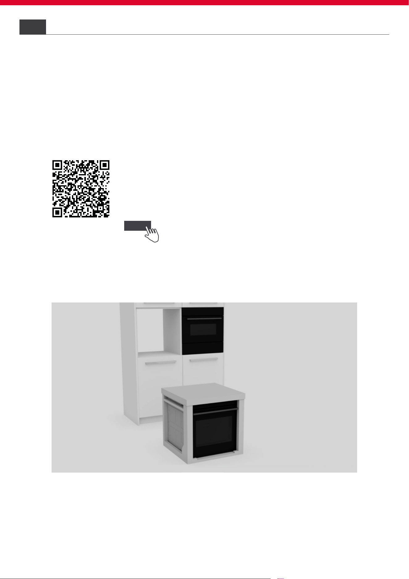
Installazione step by step
1
Posizionare il prodotto in corrispondenza del mobile per l’incasso;
oppure cliccando
al seguente
Indicazioni relative all’installazione del forno
8
8.3
Di seguito le immagini mostrano le fasi di installazione del prodotto in una
colonna.
È possibile visionare
il video d’installazione del prodotto
scansionando il Qr Code
link

27
HOOVER
2
Rimuovere l’imballaggio mediante un taglierino prestando attenzione a non
danneggiare il prodotto;
3
Rimuovere tutti gli accessori presenti nel forno e richiudere lo sportello;
Indicazioni relative all’installazione del forno
8

28
HOOVER
4
Avvicinare il prodotto in corrispondenza del mobile per l’incasso. Dopo aver
consultato il manuale di installazione, procedere con i collegamenti elettrici;
5
Sollevare il prodotto dalle maniglie laterali utilizzando dei guanti. Non sollevare
mediante maniglia dello sportello;
Indicazioni relative all’installazione del forno8

29
HOOVER
6
Inserire il prodotto nel vano di incasso;
7
Aprire lo sportello per ssare il prodotto al mobile. Avvitare il prodotto alle
estremità superiori; coprire le viti con i tappini forniti.
Indicazioni relative all’installazione del forno
8
30
HOOVER
Smontaggio del prodotto11
• Scollegare il prodotto dalla rete elettrica;
• Svitare le viti di ssaggio;
• Sollevare leggermente il prodotto ed estrarlo completamente;
• Questo prodotto non rovina il mobile, il quale potrà essere utilizzato an-
che con un nuovo elettrodomestico.
Prima messa in funzione10
Al primo preriscaldamento del prodotto possono svilupparsi leggeri odori e
fumo all’apertura dello sportello. Quando il prodotto viene acceso per la
prima volta, si possono effettuare, se disponibili, le seguenti impostazioni:
• Impostare l’ora;
• Selezionare la lingua;
• Settare luminosità e volume;
• Settare l’amperaggio;
• Per ulteriori informazioni, consulta il manuale utente del prodotto.
Consegna all’utente9
A conclusione dell’installazione:
• Informare l’utente circa le funzioni essenziali;
• Informare l’utente su tutti gli aspetti rilevanti per la sicurezza dell’uso e
della manipolazione;
• Consegnare all’utente gli accessori e le istruzioni per l’uso e il montaggio
da conservare con cura.
Al termine dell’installazione, rimuovere la pellicola protettiva, il nastro e
tutti gli altri materiali da imballaggio ed estrarre gli accessori in dotazione
dall’interno del forno.
AVVERTENZA: Il prodotto richiede una adeguata ventilazione per un funzio-
namento normale. Non ostruire per alcun motivo le aperture di ventilazione.
NOTA: L’aspetto effettivo del forno dipende dal modello scelto.

31
HOOVER

32
HOOVER