1
ATTACH YOUR RECEIPT HERE
ITEM #
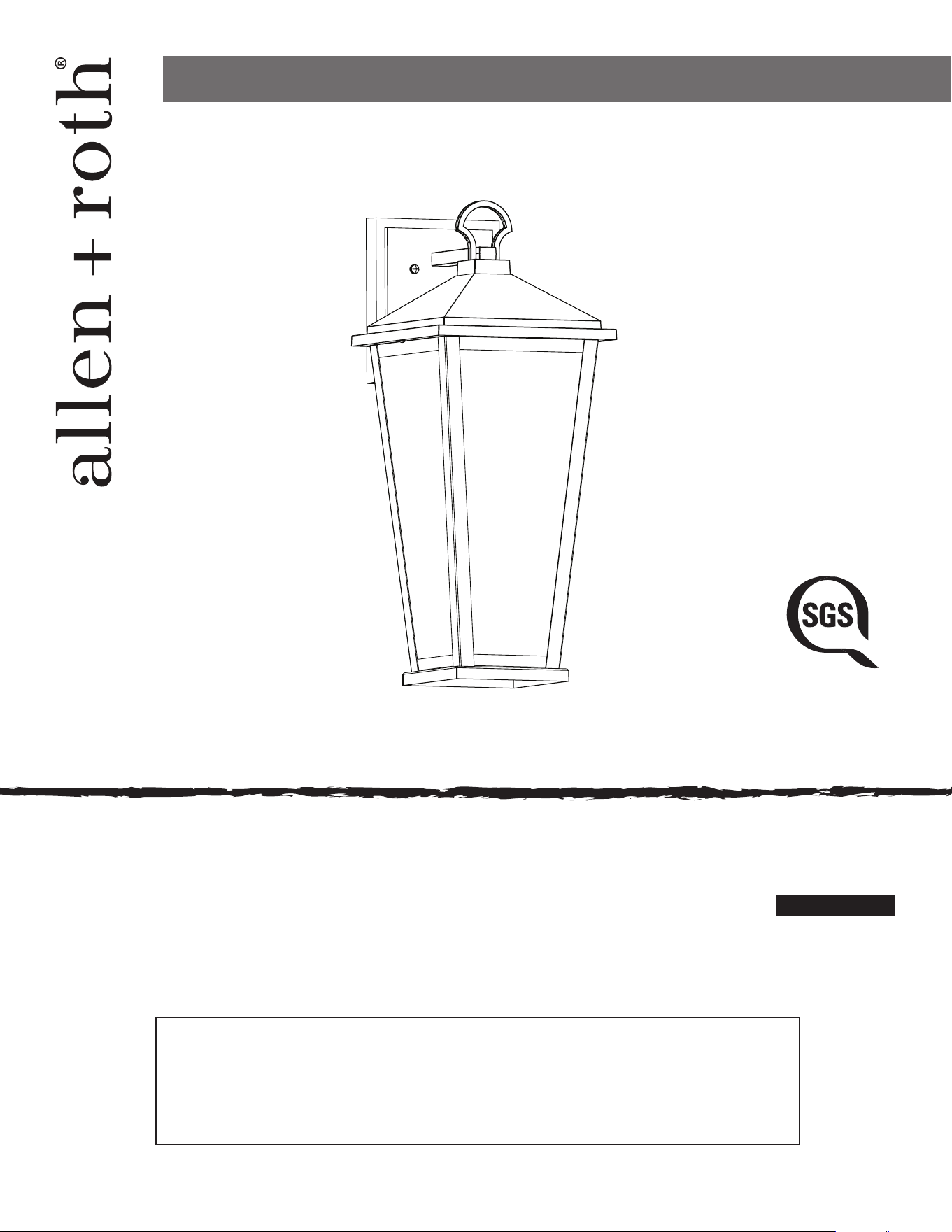
5632036
MODEL #
43077
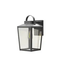
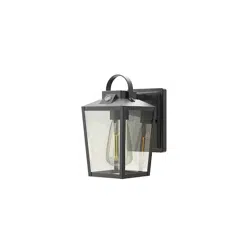
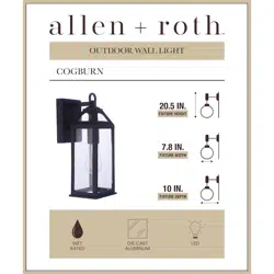
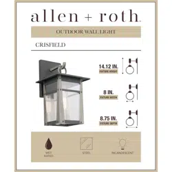
WALL LANTERN
Español p. 10
SG241216
ALLEN + ROTH and logo design are trademarks or
registered trademarks of LF, LLC. All rights reserved.
welcoming • sophisticated • inspiring
US
RATED FOR
WET
LOCATIONS
Thank you for purchasing this ALLEN + ROTH product.
Questions, problems, missing parts?
Before returning to your retailer, contact us at:
866-439-9800, 8 a.m. - 8 p.m., EST, Monday - Sunday or [email protected].
Purchase Date _________________________

2
TABLE OF CONTENTS
Package Contents. . . . . . . . . . . . . . . . . . . . . . . . . . . . . . . . . . . . . . . . . . . . . . . . . . . . . . . . . . . . . . . . . 3
Hardware Contents. . . . . . . . . . . . . . . . . . . . . . . . . . . . . . . . . . . . . . . . . . . . . . . . . . . . . . . . . . . . . . . . 3
Preparation ......................................................................3
Safety Information. . . . . . . . . . . . . . . . . . . . . . . . . . . . . . . . . . . . . . . . . . . . . . . . . . . . . . . . . . . . . . . . . 4
Assembly Instructions. . . . . . . . . . . . . . . . . . . . . . . . . . . . . . . . . . . . . . . . . . . . . . . . . . . . . . . . . . . . . . . . . . 5
Troubleshooting. . . . . . . . . . . . . . . . . . . . . . . . . . . . . . . . . . . . . . . . . . . . . . . . . . . . . . . . . . . . . . . . . . 9
3-Year Limited Warranty. . . . . . . . . . . . . . . . . . . . . . . . . . . . . . . . . . . . . . . . . . . . . . . . . . . . . . . . . . 9
3
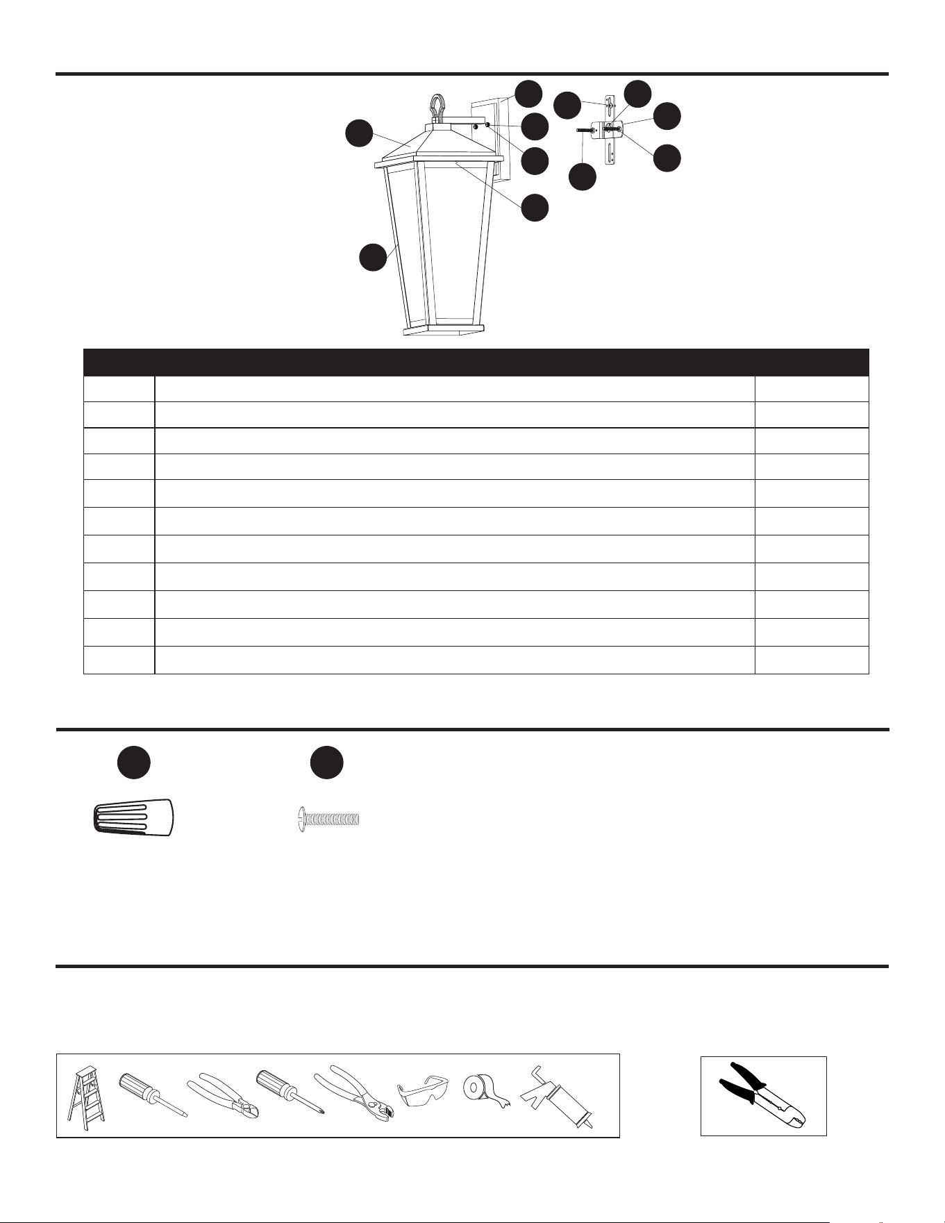
PACKAGE CONTENTS
PART DESCRIPTION QUANTITY
A Fixture 1
B Glass Frame (preassembled to Fixture [A]) 1
C Frame Screw (preassembled to Glass Frame [B]) 2
D Mounting Bracket (preassembled to Wall Plate [I]) 1
E Mounting Screw (preassembled to the Mounting Bracket [D]) 2
F Hex Nuts (preassembled to the Mounting Screw [E]) 2
G Ground Screw (preassembled to the Mounting Bracket [D]) 1
H Screw Cap (preassembled to the Mounting Screw [E]) 2
I Wall Plate (preassembled to Fixture [A]) 1
J Adjustment Screw (preassembled to the Mounting Bracket [D]) 1
K Washer (preassembled to the Mounting Screw [E]) 2
HARDWARE CONTENTS
Wire Connector
Qty. 3
Bracket Screw
Qty. 2
AA
RR
PREPARATION
Estimated Assembly Time: 60 minutes
Tools Required for Assembly (not included):
Helpful Tools (not included)
C
E
G
I J
F
A
B
D
K
H

4
SAFETY INFORMATION
Please read and understand this entire manual before attempting to assemble, operate or install the
product. Failure to do so could lead to electrical shock, re or other injuries that could be hazardous
or even fatal.
• Before you begin installing the xture, disconnect the power by removing fuses or turning o the
circuit breakers.
• The net weight of the xture is 2.99 lbs.
• RATED FOR WET LOCATIONS. This xture is intended for indoor, damp, or outdoor use.
DANGER:
• DO NOT connect this xture to an electrical system that does not provide a means for equipment
grounding. Never use a xture in a two-wire system that is not grounded. Installing a xture into
an electrical system not having a proper grounding means could cause metal parts of the xture
to carry electrical currents if any of the xture wires, wire connections or splices were to become
broken, cut or loose during the mounting or normal operation of the xture. Under this condition,
anyone coming in contact with the xture would be subject to electrical shock, which could cause
serious injury or death.
• DO NOT connect the bare or green insulation xture ground wire to the black (hot) current-carrying
wire or the white neutral house wire. Connection of the bare or green xture ground wire to the
black or white house wires may cause metal parts of the xture to carry electrical currents. Under
this condition anyone coming in contact with the xture will receive electrical shock, which could
cause serious injury or death.
• DO NOT damage or cut the wire insulation (covering) during installation of the xture. DO NOT
permit wires to contact any surface having a sharp edge. To do so may damage or cut the wire
insulation, which could cause serious injury or death from electrical shock.
WARNING:
• All electrical connections must be in agreement with local codes and ordinances, the National
Electric Code (NEC) and ANSI/NFPA 70-1999. Contact your municipal building department to learn
about your local codes, permits and/or inspections. Risk of re - most dwellings built before 1985
have supply wire rated for 140°F. Consult a qualied electrician before installation.
• To avoid personal injury, the use of gloves may be necessary while handling xture parts with sharp
edges.
• DO NOT suspend any xture by the house wires. A xture must always be mounted directly to a
an outlet box. Wire connectors will not support the weight of a xture. Suspending a xture by the
house wires and wire connectors will result in the xture falling, with the possibility of personal
injury and the danger of electrical shock or re.
• To reduce the risk of re, electrical shock, or personal injury, each wire connector used with this
light kit should accept only one 18-gauge wire from the light xture and one 18-gauge wire from the
outlet box. If there are three or more wires to connect or any of the wires is larger than 18 gauges,
consult an electrician for the proper size wire connectors to use.
5
ASSEMBLY INSTRUCTIONS
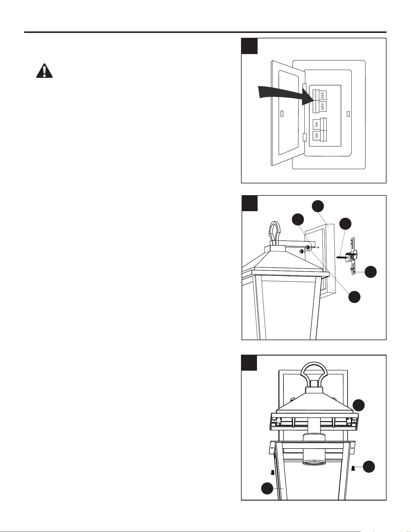
1. Turn o the circuit breakers and the wall switch to the
supply line leads.
DANGER: Failure to disconnect the power
supply prior to installation may result in serious injury
or death.
2. Remove the screw caps (H) and washers (K) from the
mounting screws (E) preassembled to the mounting
bracket (D). Remove the mounting bracket (D) from
the wall plate (I).
3. Remove the two frame screws (C) preassembled to
glass frame (B). Then remove xture (A).
1
3
C
A
I
D
E
K
H
B
2
6
ASSEMBLY INSTRUCTIONS
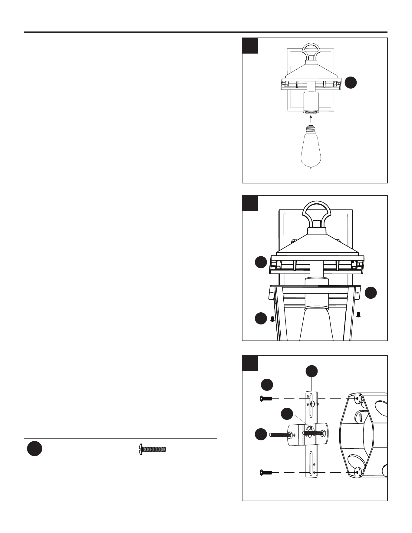
4. Install the E26-base bulb (sold separately) into the
socket of xture (A).
Note: Fixture is compatible with any E26-base LED,
CFL, or incandescent bulb (60 watt max.).
5. Lift xture (A) back onto glass frame (B). Then, use
previously removed frame screws (C) to attach xture
(A) to glass frame (B).
6. Use the bracket screws (RR) to attach the mounting
bracket (D) securely to the outlet box (sold separately).
Note: In order for xture (A) to be level, the mounting
screws (E) must be aligned exactly perpendicular to
the horizon since they will determine the orientation of
the xture. Once level, tighten adjustment screw (J) to
secure.
Hardware Used
RR
Bracket Screw x 2
4
5
6
Bulb (sold
separately)
B
D
RR
J
E
C
A
A
Outlet Box
7
ASSEMBLY INSTRUCTIONS
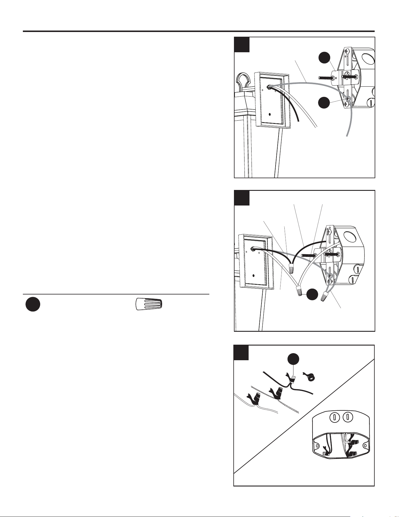
7. Loosen the ground screw on the mounting bracket
(D) and wrap the bare wire from the xture around
the ground screw (G). Tighten the ground screw (G)
to hold the bare wire in place. Note: Ensure there is
enough of the bare wire extending from the ground
screw (G) to connect to the ground wire from the
outlet box using a wire connector (AA).
8. Use wire connectors (AA) to secure the household
supply wires to the xture wires according to the
image and the following instructions:
• Connect the black (hot) supply wire to the black wire
from the xture.
• Connect the white (neutral) supply wire to the white
wire from the xture.
• Connect the bare/green (ground) supply wire to the
bare wire from the xture.
Hardware Used
AA
Wire Connector x 3
9. Wrap electrical tape (not included) around each
individual wire connector (AA) down to the wire. Turn
the spliced/taped wires upward and gently push the
wires and wire connectors (AA) into the outlet box.
WARNING: Ensure no bare wire strands are visible
after making connections. Place Green and White
wire connections on opposite sides of outlet box from
the Black.
7
8
9
AA
G
D
AA
Bare
Bare
Bare/Green (ground)
Black
Black (hot)
White
White (neutral)
8
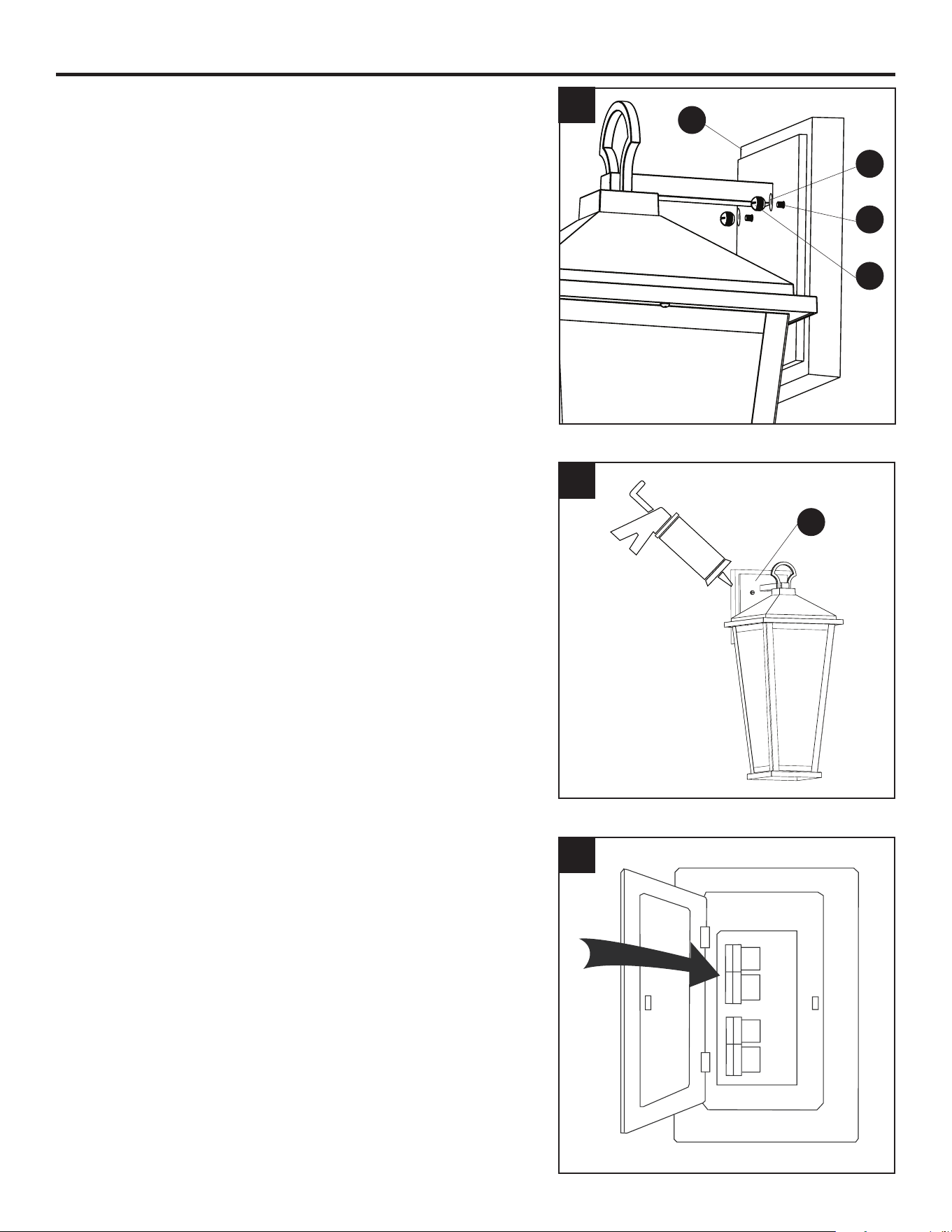
ASSEMBLY INSTRUCTIONS
10. Hang wall plate (I) on mounting screws (E). Then use
the screw caps (H) and washers (K) to secure wall
plate (I) to the mounting bracket (D).
Note: If the wall plate (I) is not ush against the wall,
remove wall plate (I) and loosen the hex nuts (F) to
allow the mounting screw (E) length to be adjusted.
Once adjusted retighten the hex nuts (F) and reinstall
the wall plate (I).
11. To prevent water, rain, or moisture from entering wall
plate (I), use waterproof caulk (sold separately) to
seal the perimeter.
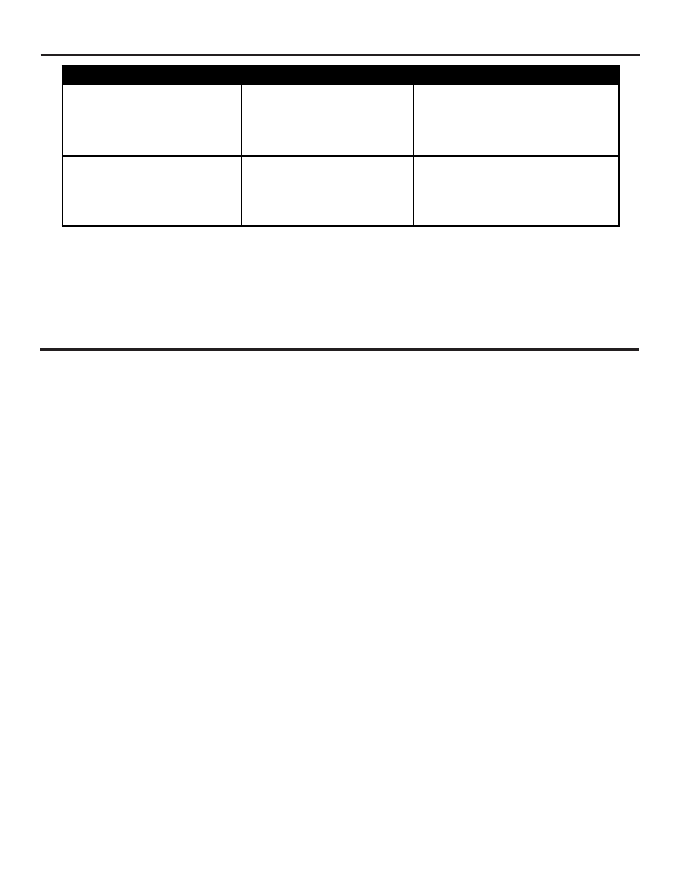
12. Restore the power at the main fuse or circuit breaker
and wall switch.
Assembly is complete.
10
I
H
K
E
12
11
I
9
TROUBLESHOOTING
THREE-YEAR LIMITED WARRANTY
The manufacturer warrants all of its lighting xtures against defects in materials and workmanship for
three (3) years from the date of purchase. If within this period the product is found to be defective,
take a copy of the bill of sale as a proof of purchase and the product in its original carton to the place
of purchase. The manufacturer will, at its option, repair, replace or refund the purchase price to the
consumer. All costs of installation and removal of the xture is the responsibility of the consumer. This
warranty does not cover xtures becoming defective due to misuse, accidental damage or improper
handling and/or installation and specically excludes liability for direct, incidental or consequential
damages. As some states do not allow exclusions of limitations on an implied warranty, the above
exclusion and limitation may not apply. This warranty gives you specic rights and you may also have
other rights which may vary from state to state.
PROBLEM POSSIBLE CAUSE CORRECTIVE ACTION
Bulb will not light. 1. Fixture may be wired
incorrectly.
2. Worn or broken bulb.
1. Check wiring.
2. Replace bulb.
Wall Plate (I) does not sit
ush with wall.
Edge of outlet box may not
be ush with wall.
Loosen and adjust the hex nuts
on the two preassembled screws.
Printed in China
9983 PB · 102324