
REFRIGERATED DRYER
2
Customer Support: 1-866-409-4581
TABLE OF CONTENTS
Table of Contents
I. Introduction __________________________________ 03
II. Precautions for Safe Operations _________________ 05
III. Technical Information _________________________ 05
IV. Principle of Operations ________________________ 06
V. Installation and Specifications __________________ 07
VI. Startup & Operations _________________________ 09
VII. Daily Maintenance ___________________________ 10
VIII. Troubleshooting ____________________________ 11
XII. Display Panel Operations _____________________ 14
XIII. Control Board Programming __________________ 14
XV. Warranty ___________________________________ 18
REFRIGERATED DRYER
Customer Support: 1-866-409-4581
3
INTRODUCTION
Thank you for purchasing a California Air Tools,
Inc. Compressed Air Refrigerated Dryer.
Please contact us if you have any questions:
Phone: 1-866-409-4581
Email: customerservice@californiaairtools.com
Record the model and serial numbers indicated on
your refrigerated dryer nameplate:
Model No.
Serial No.
Date of Purchase:
Store/Dealer:
REFRIGERATED DRYER
4
Customer Support: 1-866-409-4581
How to find a local service center:
Even quality built equipment might need service or repair parts.
Contact the California Air Tools Customer Service Department:
Phone: 1-866-409-4581
Online: WWW.CALIFORNIAAIRTOOLS.COM
Please provide the information below:
Model number and Serial number and specifications shown on
the name plate.
A brief description of the trouble with the refrigerated dryer.
Do not return your refrigerated dryer for service or parts to the
store/dealer where purchased.
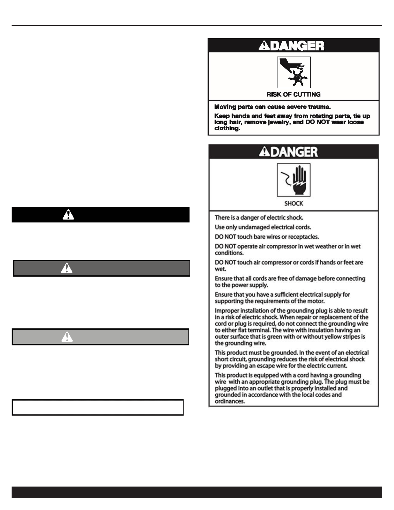
IMPORTANT SAFETY
INSTRUCTIONS
Safety Messages & Signal Words:
Indicates an immediate hazardous situation which, if not
avoided, will result in death or serious injury to the
operator or to bystanders.
DANGER
WARNING
Indicates a potentially hazardous situation which, if not
avoided, could result in death or serious injury to the
operator or to bystanders.
CAUTION
Indicates a potentially hazardous situation which, if not
avoided, may result in moderate or minor injury to the
operator or to bystanders.
Indicates a situation which, if not avoided, may result in
damage to product components or other property.
NOTICE

REFRIGERATED DRYER
Customer Support: 1-866-409-4581
5
I. Refrigerated Dryer Overview
The refrigerated dryer is dehydration equipment for compressed air that uses the principle of refrigeration to cool
the compressed air according to the correspondence between the saturated vapor pressure and temperature of
water, so that the water vapor in compressed air will be supersaturated and condensed at low temperature, and
then the compressed air will be separated from the water.
Under normal conditions, the refrigerated dryer can reduce the dew point (under pressure) of air to 2 - 10℃,
which typically satisfies requirements of most compressed air quality classes except for a few applications with
special requirements for air quality.
The main content of this manual is to instruct the customer how to use this equipment correctly and to perform
routine maintenance. The purpose of this manual is to extend the service life of the equipment, to reduce
equipment failures and to ensure the quality of compressed air. This manual provides information about this
equipment for reference. Before using this equipment, please read this manual and follow the instructions for
operation and maintenance to avoid equipment failure.
II. Precautions for Safe Operation
1. The pressure of compressed air shall not exceed 1.6 MPa or 232 PSI (pounds per square inch).
2. The operating power supply must meet the requirements.
3. The equipment must be grounded for protection.
4. Before maintenance, the power supply must be removed (unplugged and/or disconnected from source).
5. Before maintenance or assembly/disassembly, make sure that there is no pressure in the system.
Note: Please follow the above precautions to prevent personnel harm
or damage to equipment!
III. Technical Information
1. Rated working conditions of the refrigerated dryer:
※ Ambient temperature: ≤ 40℃ (less than 104F Fahrenheit)
※ Atmospheric pressure: 0.101325 MPa
※ Relative humidity: 75%
※ Pressure dew point: 2 - 10℃
※ Air pressure drop: ≤ 0.035 MPa
2. For conditions of use and additional technical specifications refer to equipment nameplate.
REFRIGERATED DRYER
6
Customer Support: 1-866-409-4581
IV. Principles of Operation
1. Compressed air flow:
The humid compressed air is first cooled by the pre-cooling reheater, and then enters the evaporator to
exchange heat with the refrigerant, the temperature is further reduced, in which the water vapor condenses into
water droplets, the air is separated from the water droplets by the air-water separator, and the water droplets are
drained from the machine by the automatic drainer, and the air separated by water is then exchanged heat with
the humid air at the inlet by the pre-cooling reheater, and the temperature rises and is drained from the outlet.
2. Refrigeration system flow:
The refrigerant compressed by the internal compressor generates high-temperature and high-pressure
superheated steam, and then condenses and liquefies after cooling through the wind condenser. After throttling
by the throttling device, the pressure and temperature are reduced, the refrigerant absorbs heat and vaporizes in
the evaporator, and then turns into a low-pressure and low-temperature gaseous state, then enters the internal
compressor to complete the refrigeration cycle.
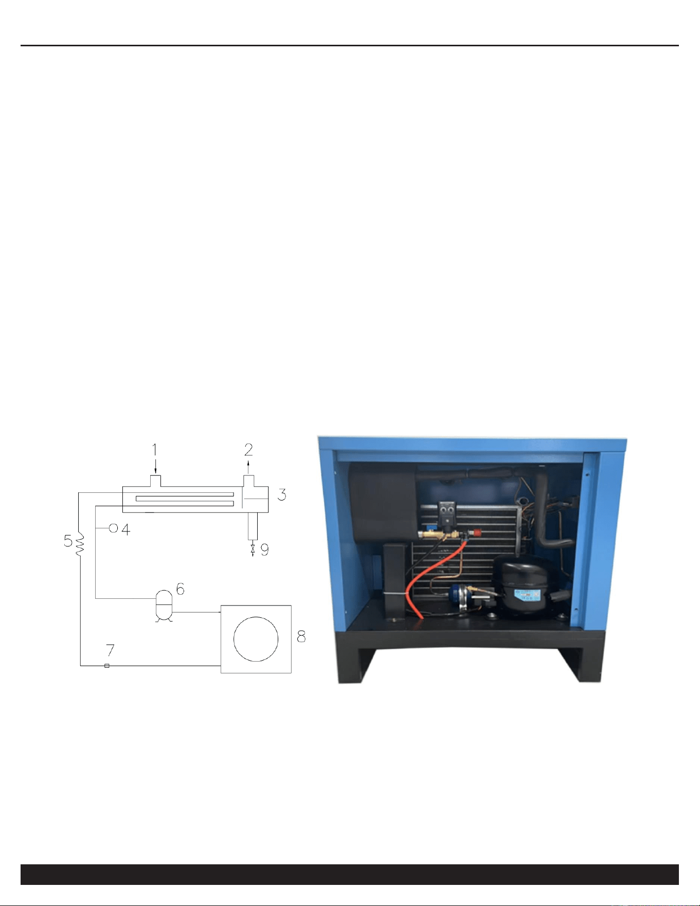
3. Refrigerated dryer system flow chart:
1: Air inlet
2: Air outlet
3: Evaporator
4: Pressure gauge
5: Flow controllers
6: Compressor
7: Pressure Switch
8: Cooling fan
9: Drainage
REFRIGERATED DRYER
Customer Support: 1-866-409-4581
7
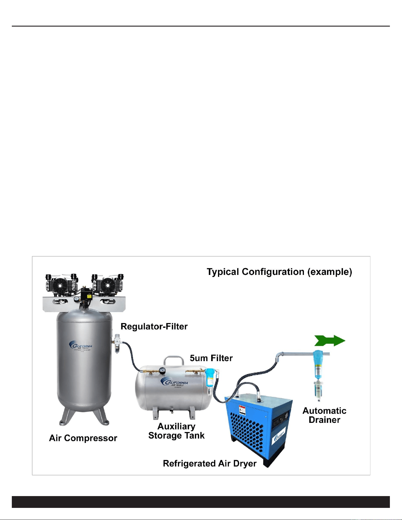
V. Installation and Specifications
1. Installation requirements:
※ If the temperature of compressed air is higher than the temperature indicated on the nameplate, it shall be
cooled with the rear cooler before entering the refrigerated dryer.
※ For piston compressor, it may be necessary to install an additional buffer air storage tank (auxiliary air
vessel) between air compressor and refrigerated dryer, to help eliminate any airflow pulse vibrations.
※ In order to avoid the contamination of the heat exchange parts of the refrigerated dryer by solid impurities
and oil in the upstream compressed air, it is recommended to install a main line filter (filtration accuracy: 3 um)
before the refrigerated dryer.
※ A shut-off valve must be installed for the inlet and outlet of the refrigerated dryer, and a bypass valve shall
be set when the working air flow cannot be cut off, which is convenient for maintenance and repair.
※ The ambient temperature of the installation location shall not exceed 100F (Fahrenheit) or 38C (Celsius).
※ It shall not be installed outdoors or in a high humidity and/or dusty place.
※ The installation location should be 2 feet away from the wall and 3 feet away from other machines for
good ventilation, cleaning and maintenance of the condenser.
※ The installation location must be on a flat level, horizontal, surface to avoid affecting the drainage.
REFRIGERATED DRYER
8
Customer Support: 1-866-409-4581
2. Piping requirements:
※ Ensure piping does not cause any vibration to the refrigerated dryer.
※ The diameter of the pipe shall not be less than the diameter of the inlet and outlet pipe, and avoid too long
or too many elbows to prevent excessive pressure drop. Avoid bending or routing piping underground to help
prevent water accumulation in the pipe.
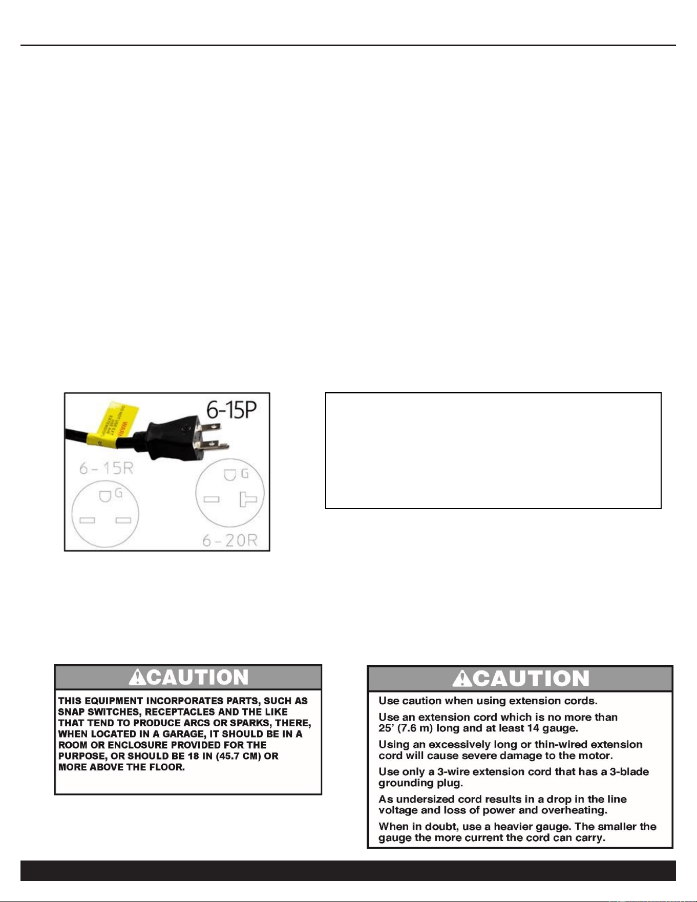
3. Electrical Requirements:
※ A special switch must be installed on the power supply side of the dryer to protect it; refer to the relevant
technical data for the switch specifications.
※ Do not use the same protection switch with other equipment.
※ The power supply voltage shall not exceed the rated voltage value (specified on the nameplate) ± 5%.
※ The specification of the power cord depends on the size of the current and the length of the line.
※ Ensure equipment is properly electrically grounded.
4. Use in Areas with Clean Air
For proper operation and to maximize the longevity of the refrigerated dryer, it is very important that the air drawn into
the dryer is clean. This could damage the dryer and impair proper operation.
Before using the refrigerated dryer, refer to the serial label for
voltage and amperage requirements. Make sure you have a
sufficient electrical supply for supporting the equipment
requirements.
Use a dedicated 15 Amp Circuit. 220 volts, 50/60 hz.
Low voltage and/or an overload circuit can cause the
overload protection system and/or circuit breaker to trip.

REFRIGERATED DRYER
Customer Support: 1-866-409-4581
9
VI. Startup & Operations
1. Check before powering on:
※ Check whether the power supply voltage is normal (±5% of the voltage on the nameplate).
※ Check whether all indications on the computer board are in the normal range and whether the fault
indicator is on (if it lights up, troubleshoot first).
※ Check whether the display on the computer board is normal (the displayed value is close to the ambient
temperature in the power off state).
2. Power on:
※ Press the ON button/switch to start, the compressor indicator light will flash, and the compressor will start
to work in three minutes, then this refrigerated dryer will enter the normal working state.
※ Check the following instrument displays and indicators:
(a) The operation light will be on, and the digital tube will display the current dew point temperature.
(b) The compressor light will be on, and the compressor will work normally.
(c) The drain indicator will light up intermittently (according to the set value of drain time), and the drain
will work when it is on.
(d) The fan indicator will be on or light up intermittently (according to the current condensing
temperature), and the fan will work when it is on.
※ After the dryer runs for three (3) minutes, open the outlet air valve, and then open the inlet air valve.
※ Check and record whether the air temperature and pressure at the inlet and outlet are normal.
3. Power off:
※ Normal power off: Press the OFF button/switch to stop the dryer compressor.
Note: Pay special attention to the following during normal operations:
※ Avoid no-load running for a long time.
※ Operations for powering on/off:
(a) Power on: Power on the air compressor or open the air valve only after the dryer has been running for 3 -
5 minutes.
(b) Power off: First power off the air compressor or close the air valve, and then power off the dryer.
Note: The above operations for powering on and off the dryer are to ensure that untreated compressed air
does not enter the end of the pipeline.
※ It is better to use ball valves, as valves at the air inlet and outlet or bypass valves, to ensure that the
middle bypass valves are not misused or not closed tightly to cause undesirable gas to enter the end of the
pipeline.

REFRIGERATED DRYER
10
Customer Support: 1-866-409-4581
※ The air pressure shall not exceed 1.0 MPa (145 PSI); the air temperature at the inlet shall not exceed
45℃ (113 degrees Fahrenheit); and the ambient temperature shall not exceed 38℃ (104 degrees Fahrenheit)
※ This dryer is fully protected with protection units/circuitry, and has the following features (for general
operation, only use the start and stop button).
(a) Delay and balance the pressure on the high and low pressure side of the refrigeration system to
facilitate the start of the compressor.
(b) Refrigerant over high pressure switch (HPS) for protection.
(c) Over-current protector (KR) to prevent the compressor from overloading.
(d) There are throttle valves, hot-gas bypass valves, condensing temperature control, etc. in the refrigerant
system, which can automatically compensate the inlet air characteristics in the normal operating range.
※ The control of this dryer adopts the automatic control of the computer board, and the temperature of each
place can be viewed at any time during the operation.
Note: Check and record the temperature regularly.
1. Avoid no-load running for a long time.
2. After powering off, wait for three minutes and power it on again to avoid continuous switching, which
may cause the compressor to trip.
VII. Daily Maintenance
1. The ideal ambient temperature of the refrigerated dryer should not be lower than 10℃ (50 degrees
Fahrenheit) in order to prevent the compressor being burnt due to lack of oil (insufficient flow) caused by the
condensation of the refrigerating oil and the delayed filling.
2. Pay attention to whether the inlet temperature of the dryer exceeds the rated value: check daily whether
the indications of the computer board are normal.
3. Check the automatic drainer daily to avoid blocking and drainage problems. If it is blocked, close the ball
valve at the front of the solenoid valve and remove the solenoid valve for cleaning.
4.Check the surface of the blades of the air condenser for dirt accumulation every month; sweep and clean it
regularly.
5. Listen to whether the compressor is running smoothly without noise.
6. The air bypass valve must be kept in fully closed position during normal use.
7. Check all electrical contacts for looseness every month.
REFRIGERATED DRYER
Customer Support: 1-866-409-4581
11
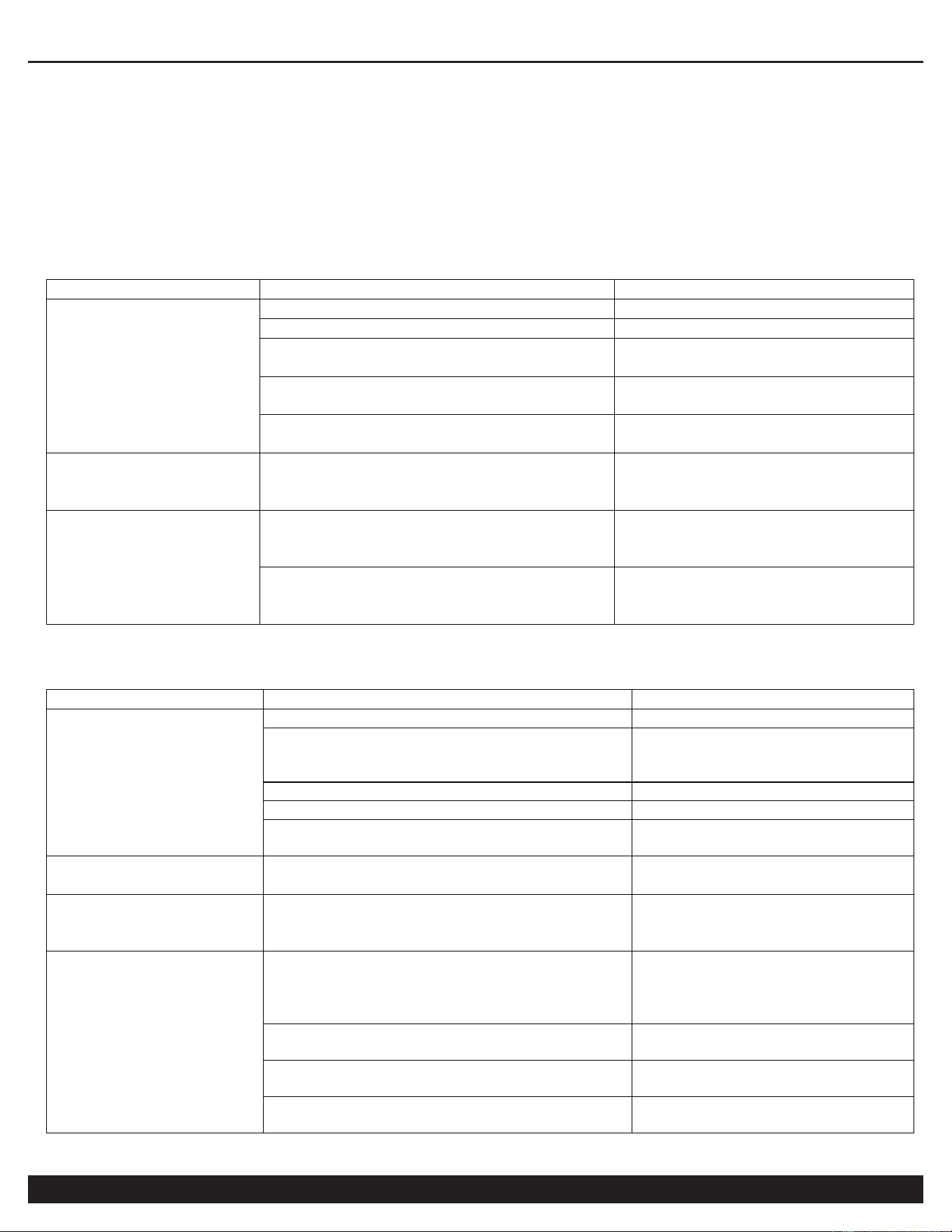
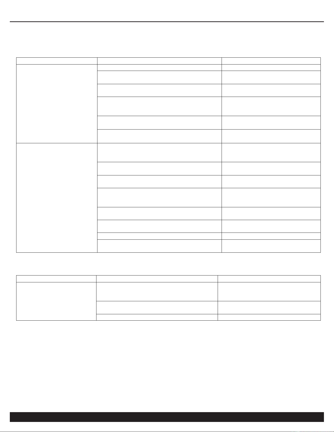
VIII. Troubleshooting
Refrigerated dryer failures and causes, including external factors, may include:
1. The pressure drop is too high.
Failure
Cause
Troubleshooting
Piping system
error
The pipeline valve is not fully opened.
Open the valve fully.
The diameter of the pipe is too small.
Increase the pipe diameter.
The pipe is too long, with too many
elbows and connections.
Redesign the pipeline system.
The filter in the pipeline is blocked.
Clean the filter or replace the
filter element.
Too many air leaks in the pipe
connection.
Check the elbows and
connections.
The air flow
exceeds the rated
value.
The flow exceeds the rated flow rate of
the refrigerated dryer, so that the
pressure drop increases naturally.
1. Replace the refrigerated
dryer with a larger capacity.
2. Reduce the air flow.
The condensate in
the evaporator
freezes.
The pressure switch is malfunctioning.
Replace it with a new one,
check the whole pipeline and
correct the switch.
The expansion valve or hot-gas
bypass valve is malfunctioning.
Replace it with a new one,
check whether the pipeline is
blocked and correct the switch.
2. The dewatering effect of the refrigerated dryer is faulty.
Failure
Cause
Troubleshooting
Piping system error
The bypass valve is not fully opened.
Close the bypass valve tightly.
The air cannot pass through the dryer.
Close the bypass valve tightly
and open the inlet and outlet
valves of the dryer.
The dryer is not placed horizontally.
Place it horizontally.
The automatic drain tilts.
Place it horizontally.
The drain line is higher than the automatic
drain.
Redesign the drain line.
The air flow is too
much.
The heat load is too high.
Redesign the air source.
The drainage
system is
abnormal.
The drainer is malfunctioning.
Clean or replace it with a new
one.
The indication of
the dew point
temperature is
abnormal
The dew point temperature is too low or
too high.
Adjust the pressure switch,
water flow adjustment valve,
expansion valve and hot-gas
bypass valve.
The ambient or inlet temperature is too
low.
Not a critical error; you may
continue to use this dryer.
The inlet temperature is too high.
Add a rear cooler or improve
the inlet air temperature.
The refrigerant leaks and the cooling effect
is poor.
Repair the leaks and fill the
refrigerant.
REFRIGERATED DRYER
12
Customer Support: 1-866-409-4581
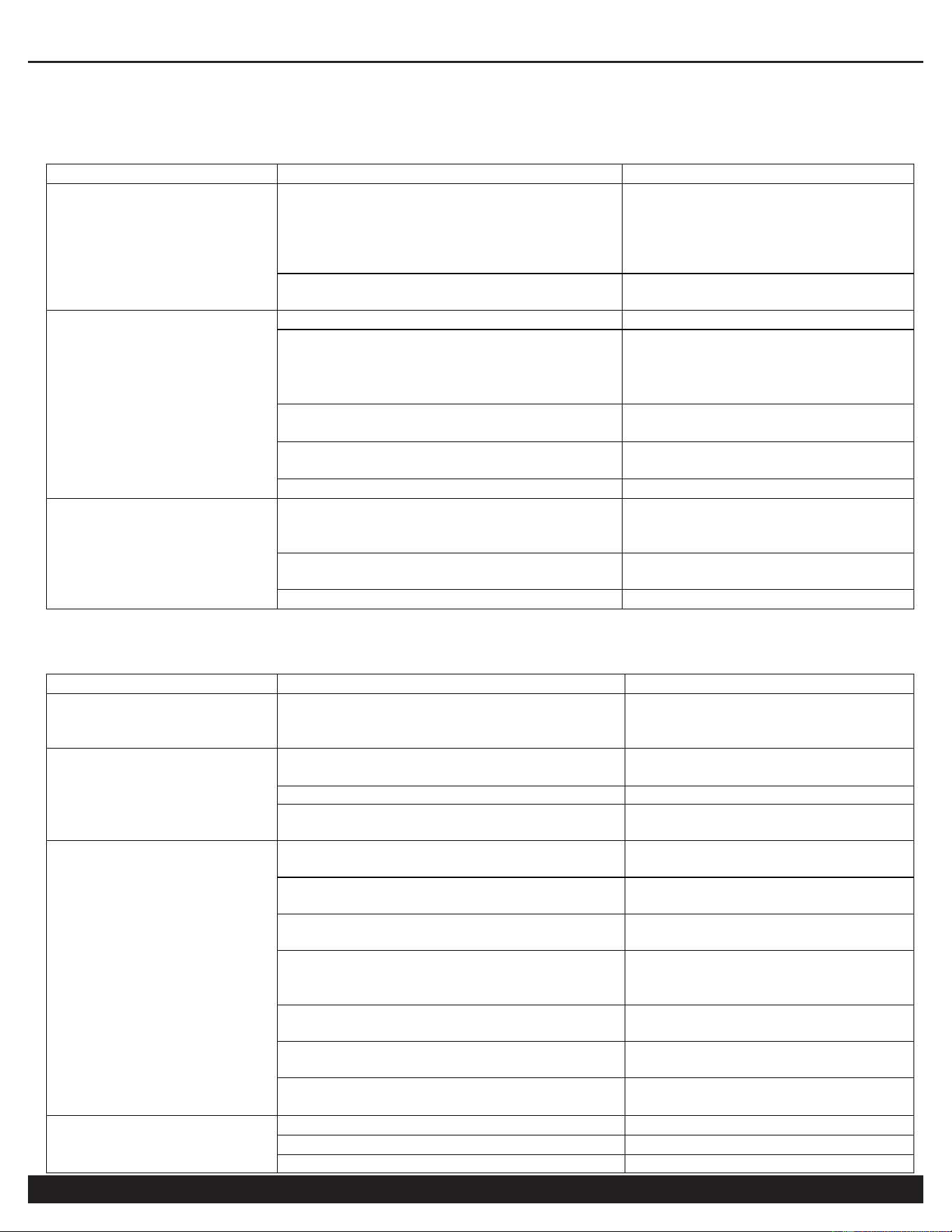
3. Refrigerated Dryer Fails to Start or Function.
Failure
Cause
Troubleshooting
The power supply
cannot be supplied
normally.
The fuse is blown or it trips due to no
fuse.
Confirm whether the power
supply is under-phase
disconnected or grounded, and
check whether the fuse switch
is damaged.
The wire is broken.
Find out where the wire is
broken and repair it.
The power supply is
well supplied, but it
still cannot be
started.
The control switch is malfunctioning.
Replace it with a new one.
The voltage is abnormal.
Please refer to the rated
voltage indication on the
nameplate, with the tolerance
range of ± 5%.
The AC contactor or thermal relay is
malfunctioning.
Replace it with a new one.
The high-/low-pressure switch is
malfunctioning.
Replace it with a new one.
The compressor is malfunctioning.
Replace it with a new one.
All the switches are
normal, but it still
cannot be started.
It is not reset after the high-/low-
pressure tripping, and the
electromagnetic switch is not reset.
Find out the reason of tripping,
then reset it.
The wire is loose.
Find out where the wire is not
locked and tighten it.
The compressor is malfunctioning.
Replace it with a new one.
4. Post Start Failure Issues.
Failure
Cause
Troubleshooting
The power supply is
abnormal.
The wire is short-circuited shortly after
starting, and then produces a burning
smell
Set the lines and switches
again to find out the cause of
abnormalities.
The high-voltage trip
has been reset, but it
still cannot be
started.
The high-voltage trip switch is
malfunctioning.
Replace the switch with a new
one.
Overload tripping
Connect a relay.
The dirt on air condenser blades is too
much.
Sweep and clean it.
Overload trip
Continuous starting
Each start must be separated
by more than 3 minutes.
Under-phase of power supply
The contact of fuse or power
switch is not good.
The compressor is overloaded.
The dryer is overloaded,
please reduce air flow.
The inlet temperature of the dryer is too
high.
Add a rear cooler or improve
the cooling conditions of the air
compressor.
The setting value of the thermal relay is
too low.
Adjust the set value.
Power supply electrical connectivity,
including wiring, may be poor or faulty.
Clean or replace it with a new
one.
The contactor is malfunctioning, or the
electrical connectivity is insufficient.
Clean or replace it with a new
one.
Overload trip
The pressure switch is malfunctioning.
Replace it with a new one.
The fan motor is malfunctioning.
Replace it with a new one.
The fan blade is stuck or loose.
Repair to make it run normally.
REFRIGERATED DRYER
Customer Support: 1-866-409-4581
13
5. Dryer is operating, but output values are incorrect.
Failure
Cause
Troubleshooting
The indication of the
dew point
temperature is too
low.
The temperature sensor is damaged.
Replace it with a new one.
The throttle or hot-gas bypass valve is
malfunctioning.
Replace it with a new one.
The refrigeration system leaks.
Repair the leaks and fill the
refrigerant.
The refrigerant filling line is blocked.
Change the desiccant and re-
evacuate it, then fill the
refrigerant.
The setting of condensing temperature
is improper.
Set the condensing
temperature to 42℃.
The ambient temperature is too low.
The ambient temperature
shall not be lower than 10℃.
The indication of the
dew point
temperature is too
high.
The inlet temperature is too high (over
45 ℃ or 113 Fahrenheit)
Add a rear cooler or improve
the cooling conditions of the
air compressor.
The expansion valve or hot-gas bypass
valve is malfunctioning.
Replace it with a new one.
The dirt on air condenser blades is too
much.
Sweep and clean it.
The ambient temperature is too high or
the ventilation is not good.
Improve the cooling
conditions and ventilate the
room.
The air flow is too much and the
pressure is below 0.4 Mpa.
Control the air outlet.
The setting of condensing temperature
is improper.
Adjust the set value.
The sensor is malfunctioning.
Replace it with a new one.
The fan blade is stuck or loose.
Repair to make it run
normally.
6. The automatic drainage system is not functioning correctly.
Failure
Cause
Troubleshooting
The drainage is not
performing correctly.
The used pressure is below 1.5 kg/cm
2
.
The pressure for automatic
drain shall be in the range of 2-
10 kg/cm
2
.
The drain valve is damaged or not fully
opened.
Replace it with a new one or
open the valve.
The drainer is blocked.
Clean it.
IX. Working conditions:
9.1. Working voltage: 220VAC ± 10% 50/60Hz.
9.2. Output relay contact capacity: 10 A / 220 VAC.
9.3. Working internal ambient temperature: -5 - 60℃; working relative humidity: 10 - 90% non-condensation.
9.4. Storage temperature: -25 - 75 ℃.
REFRIGERATED DRYER
14
Customer Support: 1-866-409-4581
X. Specifications and Size:
10.1. Size of the whole machine: L 85. 0 * H 35.0 * D 63. 8 (mm).
10.2. Installation size: L 71 * W 29 (mm).
10.3. Length of the sensor bus: 1 m (including the length of the probe).
XI. Functions and Technical Parameters:
11.1. Temperature control range: -20 - 120℃.
11.2. Temperature measurement range: -20 - 145℃.
11.3. Display accuracy: 1℃ (-20℃ - -10℃/100℃ - 145℃)/0.1℃(-10℃ - 100℃).
11.4. For -20℃ - 120℃, ±1℃±0.5; for others, ±2℃.
11.5. Sensor type: NTC (10 kΩ/25℃, Heat-sensitive electrical resistance: 3435K).
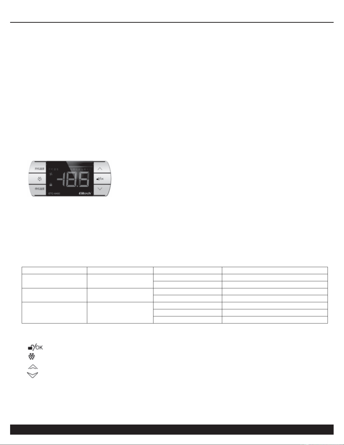
XII. Display Panel Operations
(1) Operation of the display panel
The display panel can display three numbers, two status indicators (button lock, fan), and two parameter names
(power-on temperature, power-off temperature).
In the normal running, all the parameter names will not light up; when entering the menu setting, the
corresponding parameter names will light up. When there is output in the normal running, the "ON" character will
light up; in the process of powering off, the "OFF" character will light up.
(2) Working indicator description
Name
Symbol
Status
Description
Lock symbol
Off
Non-locked
On
Locked
Output symbol
Power on
Off
Fan output stopped
On
Fan output working
Fan symbol
Off
Fan stopped
Flashing
Fan delayed
On
Fan working
(3) Button description
There are six buttons on the controller:
: Unlock/OK;
: Reset; "Power-on temperature"; "Power-off temperature";
: temperature +;
: temperature -.
XIII. Control Board Programming
13.1. Unlock and lock the controller
REFRIGERATED DRYER
Customer Support: 1-866-409-4581
15
Press and hold "Unlock/OK" for 5 seconds in the locked state of the controller, "0" will be displayed now; then
enter the password "-15" and press "Unlock/OK", the " " symbol will go out, which indicates that the controller is
successful unlocked and now you can enter the parameter setting. If the password is wrong, it will return to the
normal interface. The controller will lock automatically after 10 seconds without pressing any button.
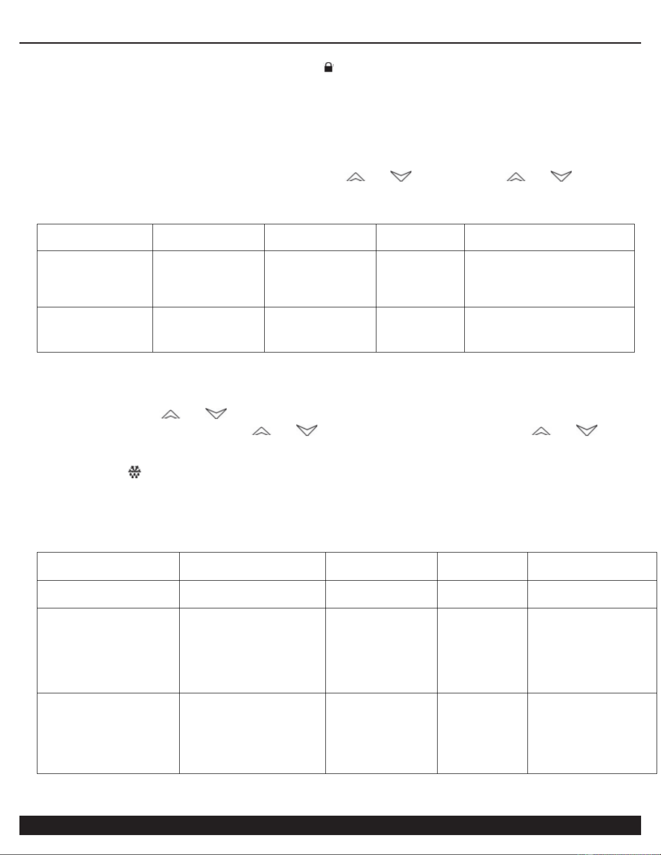
13.2. User menu setting
In the normal running and unlocked state, press "Power-on temperature" (or "Power-off temperature"), the
corresponding parameter name will light up and the display window will display the "Power-on temperature" (or
"Power-off temperature"), which indicates that you have entered the "Power-on temperature" (or "Power-off
temperature") menu. The parameters can be adjusted by " " or " ", press and hold " " or " " to
adjust the parameter quickly. In the setting state, the parameters will be saved and the setting state will be exited
after 5 seconds without pressing any button.
Parameter
name
Description
Setting
range
Factory
setting
Remark
"Power-on
temperature"
ON
Power-on
temperature
Power-off
temperature
- +145℃
35.0℃
The temperature of the fan
control sensor is higher
than the power-on
temperature when the fan
starts.
"Power-off
temperature"
OFF
Power-off
temperature
-20℃ -
Power-on
temperature
34.5℃
The temperature of the fan
control sensor is lower than
the power-off temperature
when the fan stops.
13.3. System menu setting
In the normal running and the unlocked state, press and hold "Unlock/OK" for more than 3 seconds until the
parameter code "F0" is displayed in the temperature display, which indicates that you have entered the system
menu setting. Press " " or " " to switch the parameter code item; press "Unlock/OK" to display the
corresponding parameter value, press " " or " " to adjust the parameter, press and hold " " or " " to
adjust the parameter quickly; in the system menu setting state, the adjusted parameter will be saved, the system
menu setting state will be exited and it will return to the normal interface after 5 seconds without pressing any
button. Press " " in the normal running to view the fan control temperature, and after 6 seconds, it will return to
the normal interface.
XIV. Parameter Table
Parameter
Description
Setting
range
Factory
setting
Remark
F0
Fan start delay
0-120
minutes
0
minutes
F1
Upper limit of the
fan control
temperature alarm
Lower limit
of the fan
control
temperature
alarm - 145
℃
120℃
H1
F2
Lower limit of the
fan control
temperature alarm
-20℃ -
Upper limit
of the fan
control
temperature
alarm
-10℃
LA1
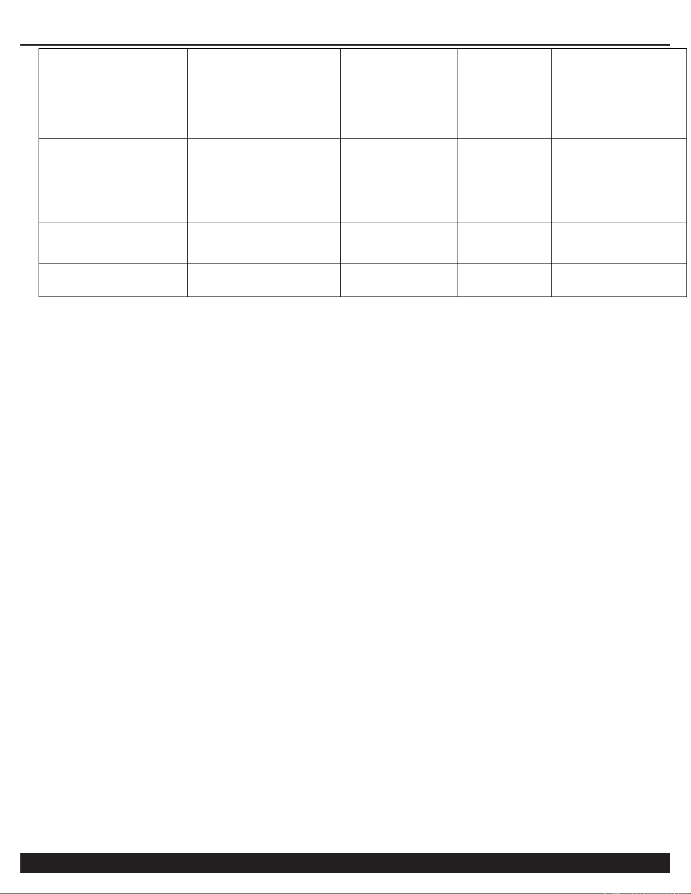
REFRIGERATED DRYER
16
Customer Support: 1-866-409-4581
F3
Upper limit of the
storage
temperature alarm
Lower limit
of the
storage
temperature
alarm - 145
℃
30℃
H2
F4
Lower limit of the
storage
temperature alarm
-20℃ -
Upper limit
of the
storage
temperature
alarm
-10℃
LA2
F5
Storage
temperature
sensor correction
-10.0 -
10.0℃
-1.0℃
F6
Fan control sensor
correction
-10.0 -
10.0℃
0.0℃
(1) Power-on temperature
When the fan control temperature is higher than the set value, the output will be turned on.
(2) Power-off temperature
When the fan control temperature is lower than the set value, the output will be turned off.
(3) P0 - Fan start delay
It needs to go through the set delay time before it starts normally.
(4) F1 - Upper limit of the fan control temperature alarm
When the temperature of the fan control sensor (PB1) is higher than the upper limit of the fan control temperature
alarm, the thermostat will display alarm H1 and the buzzer will beep.
(5) P2 - Lower limit of the fan control temperature alarm
When the temperature of the fan control sensor (PB1) is lower than the lower limit of the fan control temperature
alarm, the thermostat will display alarm LA1 and the buzzer will beep.
(6) P3 - Upper limit of the storage temperature alarm
When the temperature of the storage temperature sensor (PB2) is higher than the upper limit of the storage
temperature alarm, the thermostat will display alarm H2 and the buzzer will beep.
(7) F4 - Lower limit of the storage temperature alarm
When the temperature of the storage temperature sensor (PB2) is lower than the lower limit of the storage
temperature alarm, the thermostat will display alarm LA1 and the buzzer will beep.
8) F5 - Storage temperature sensor correction
When there is an error in the measured storage temperature, the temperature can be corrected by adding or
subtracting this parameter.
(9) F6 - Fan control sensor correction
When there is an error in the fan control temperature, the temperature can be corrected by adding or subtracting
this parameter.
(10) Error code
When the sensor is malfunctioning, there will be a corresponding alarm code, please quickly detect whether the
sensor is shorted, or measured beyond the range. E1 will be displayed for PB1 and E2 for PB2.
9. Eliminate buzzer alarm
Press any button to eliminate the sound of the buzzer alarm, but the alarm indicator will not go out until after the
REFRIGERATED DRYER
Customer Support: 1-866-409-4581
17
alarm is lifted.
10. One-key restore the factory settings
When the thermostat is just powered on, within 5 seconds, press and hold " " for more than 5 seconds, the
thermostat parameters will be restored, and then "end" will be displayed.
11. Self-check for controller output
Press and hold " " for more than 2 seconds within 2 seconds of power on, the controller will display from 111
to 888. Within 10 seconds after displaying 888, press the "Power-on temperature", " " and "Power-off
temperature" respectively, the corresponding symbol will light up. Press " " and "Unlock/OK" respectively, the
relay and buzzer will output.
Note: This self-check function of controller output is only for quick test of the product, and it is strictly forbidden to
use this function on the final product.
12. Fan control
Fan start conditions (while meeting all the following conditions):
- The fan delay times out.
- The storage temperature of the fan control is higher than the power-on temperature.
Compressor power-off conditions (while meeting any of the following conditions):
- The storage temperature of the fan control is lower than the power-off temperature.
- The temperature sensor of the fan control is malfunctioning.
13. Alarm output
The controller has a buzzer alarm output. In the running state, the buzzer will beep when the following situations
occur.
- When PB1 probe is malfunctioning, the temperature display window will display the error code E1; when
PB2 probe is malfunctioning, the temperature display window will display the error code E2.
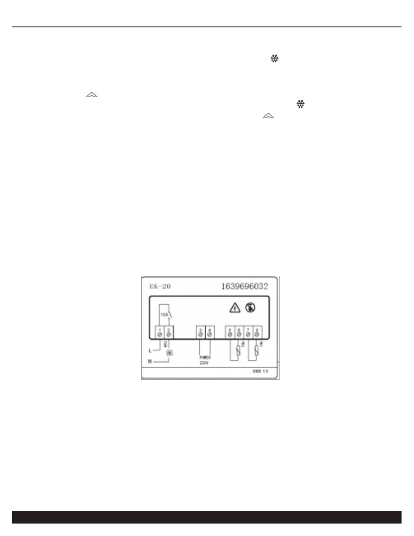
14. Wiring schematic
15.1. Precautions for chip production
★ Prevent the burning port from blocking by tin!
15.2. Safety precautions
★ Power supply board: The back is brushed with Three-Proof paint to enhance the electrical isolation
performance. And manually re-lay the tin to full on the relay circuit.
★ Display board: When assembling, the small touch circuit board must be installed close to the front panel
to prevent an air gap. If the button does not work in the debugging stage, there may be a problem when
assembling the small touch circuit board, please readjust it.

REFRIGERATED DRYER
18
Customer Support: 1-866-409-4581
XIV. California Air Tools Inc. Limited Warranty
This warranty is limited to Refrigerated Dryers distributed by: California Air Tools, Inc.
8560 Siempre Viva Road
San Diego, CA 92154
Limited Warranty
California Air Tools Inc. will repair or replace, free of charge to the original retail customer who purchased a California Air
Tools, Inc. Refrigerated Dryer from California Air Tools or from an authorized dealer, distributor or distributor’s dealer in
North America.
This warranty does not transfer to subsequent owners.
California Air Tools Inc. will repair or replace, at its option, any parts of the refrigerated dryer that are proven by an
authorized service center to be defective in material or workmanship under normal use during the applicable warranty
time period as stated below. This limited warranty covers the cost of the replacement parts and labor for all defects when
installed by an authorized service center. Transportation charges are the responsibility of the customer. Any part
replaced under warranty becomes the property of California Air Tools Inc.
All parts replaced under warranty will be considered as part of original product, and any warranty on those parts will
expire coincident with the original product warranty.
Limited Warranty Periods
Non-commercial / Non-rental (personal use by a retail customer):
1 year parts and labor Commercial / Rental (usage for income, business use):
1 year parts and labor
The limited warranty period begins on the date of retail purchase by the original purchaser.
Disclaimers, Limitations of Remedies & Exclusions
This warranty gives you specific legal rights, and you may also have other rights which may vary from state to state.
Disclaimer of Other Warranties
To the fullest extent permitted by applicable law, this limited warranty is exclusive and expressly in lieu of any and all
other warranties, including, without limitation, any implied warranties of merchantability or fitness for a particular purpose
or any other implied warranties that may arise from the course of dealing or usage of the trade. California Air Tools Inc.
hereby declaims and excludes all other warranties. To the extent that California Air Tools Inc. products are consumer
products under applicable federal and state law with respect to any customer, the duration of any implied warranties
(including but not limited to implied warranties of merchantability or fitness for a particular purpose) are limited to the
shortest duration permitted by applicable law or the Limited Warranty period provided herein, whichever is longer.
Limitations of Remedies
California Air Tools Inc. shall not be liable to customer, or anyone claiming under customer, for any other obligations or
liabilities, including but not limited to, obligations or liabilities airing out of breach of contract or warranty, negligence or
other tort or any theory of strict liability, with respect to the air compressor or California Air Tools Inc. acts or omissions
or otherwise. To the fullest extent permitted by applicable law, California Air Tools Inc. shall not in any event be liable for
incidental, compensatory, punitive, consequential, indirect, special or other damages, including but not limited to loss of
use, loss of income, loss of time, loss of sales, injury to personal property, or liability customer incurs with respect to any
other person, or any other type or form of consequential damage or economic loss.

REFRIGERATED DRYER
Customer Support: 1-866-409-4581
19
Exclusions
In addition to the foregoing disclaimers, limitations and terms, this limited warranty shall not apply to and does not
cover accessories, nor does it cover products that are in any way subject to any of the following:
1. Improper setup, installation or storage.
2. Lack of proper maintenance and service.
3. Accident, damage, abuse or misuse.
4. Abnormal operating conditions or applications.
5. Repair or modification by customer or any third party without written consent of California Air Tools Inc.
6. Use under operating conditions or in applications not recommended by California Air Tools Inc.
7. Normal wear.
8. The use of accessories or attachments not recommended by California Air Tools Inc.
9. Acts of God.
The application of these exclusions will be determined at the sole discretion of California Air Tools Inc.
Maintenance & Troubleshooting Guide
California Air Tools provides Maintenance & Troubleshooting Guide on our website
WWW.CALIFORNIAAIRTOOLS.COM.
Valuable information regarding set-up, operation and maintenance.
Please visit our website and view support videos for beneficial information.
Service or Parts
Warranty is also available by keeping and showing your original receipt from the date of purchase to an Authorized
California Air Tools Service Center.
For all customer service inquiries call 1-866-409-4581 or visit
WWW.CALIFORNIAAIRTOOLS.COM
Go to the “Contact Us” Tab