
VIVOTEK
2 - User's Manual
Table of Contents
Overview
....................................................................................................................................................................
3
Revision History ..................................................................................................................................................... 3
Read Before Use .................................................................................................................................................... 4
Package Contents .............................................................................................................................................. 4
Symbols and Statements in this Document ............................................................................................................ 8
Physical Description ............................................................................................................................................... 8
Mounting Options ................................................................................................................................................. 12
Ceiling Mount ....................................................................................................................................................... 14
Software Installation ............................................................................................................................................. 23
Network Deployment ............................................................................................................................................ 33
Ready to Use ........................................................................................................................................................ 37
Accessing the Network Camera
...........................................................................................................................
38
Using Web Browsers ............................................................................................................................................ 38
Using RTSP Players ............................................................................................................................................. 41
Using 3GPP-compatible Mobile Devices .............................................................................................................. 42
Using VIVOTEK Recording Software ................................................................................................................... 43
Main Page
................................................................................................................................................................
44
Client Settings
.........................................................................................................................................................
50
Conguration
...........................................................................................................................................................
55
System > General settings ................................................................................................................................... 56
System > Homepage layout ................................................................................................................................ 59
System > Logs ..................................................................................................................................................... 62
System > Parameters .......................................................................................................................................... 65
System > Maintenance ......................................................................................................................................... 66
Media > Image ................................................................................................................................................... 70
Media > Video ...................................................................................................................................................... 83
Media > Video ...................................................................................................................................................... 85
Media > Audio....................................................................................................................................................... 94
Media proles ....................................................................................................................................................... 96
Network > General settings .................................................................................................................................. 97
Network > Streaming protocols ........................................................................................................................ 104
Network > SNMP (Simple Network Management Protocol) ............................................................................... 11 5
Network > FTP ................................................................................................................................................... 116
Bonjour ............................................................................................................................................................... 11 7
Security > User accounts ................................................................................................................................... 118
Security > HTTPS (Hypertext Transfer Protocol over SSL) ..................................................................... 120
Security > Access List ....................................................................................................................................... 127
PTZ > PTZ settings ............................................................................................................................................ 133
Event > Event settings........................................................................................................................................ 137
Applications > Motion detection.......................................................................................................................... 154
Applications > DI and DO ................................................................................................................................. 157
Applications > Tampering detection ................................................................................................................... 158
Applications > Audio detection ......................................................................................................................... 159
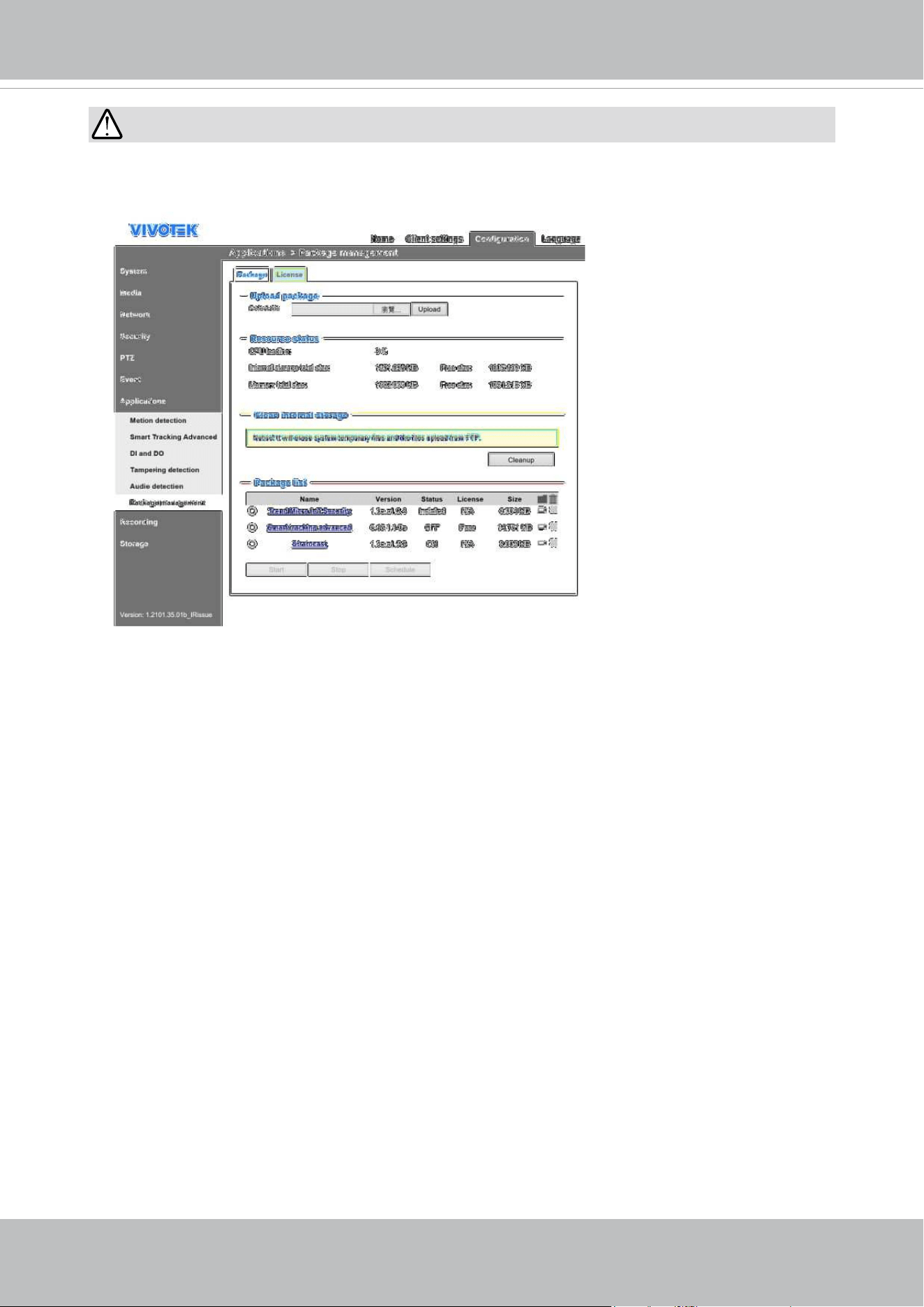
Applications > Package management - a.k.a., VADP (VIVOTEK Application Development Platform) ............. 161

VIVOTEK
User's Manual - 3
Recording > Recording settings ..............................................................................................................164
Storage .................................................................................................................................................... 169
Storage > SD card management ..............................................................................................................169
Storage > NAS management ...................................................................................................................170
Storage > Content management ..............................................................................................................172
Technology License Notice .......................................................................................................................176
Electromagnetic Compatibility (EMC) .......................................................................................................177
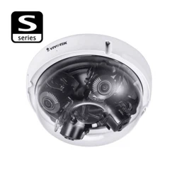
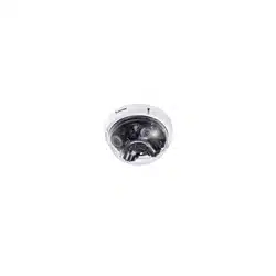
Overview
The new MA9322-EHTVL is the most versatile product offering to date from VIVOTEK.
The MA9322-EHTVL expands on the already versatile MA9321-EHTVL by adding IR
illumination up to 30 meters, providing high resolution images through four independent
sensors, and remote focus lenses. By having each sensor independent of each other, the
MA9322-EHTVL can view four different regions simultaneouslyand therefore reduce the
total number of cameras needed for surveillance, helping to lower total installation time and
costs.
Featuring four independent 5MP CMOS Sensors with IR illuminators, the MA9322-EHTVL
network camera can provide the most flexibility in surveillance monitoring. Each sensor
utilizes a 3.7 to 7.7 mm remote focus lens and 3-axis design along a circular track to
enable full 360° coverage. This enables the MA9322-EHTVL to capture every angle for
comprehensive video coverage from a single IP address, making this camera ideally suited
for surveillance in areas such as hallway intersections, building corners, parking garages/
lots, and shopping malls. Now with added IR illuminators, areas of low light visibility are no
longer an issue either.
The MA9322-EHTVL is equipped with a removable IR-cut lter and WDR Pro technology,
enabling the camera to maintain optimal image quality and unparalleled visibility in high
contrast lighting environments. Furthermore, the MA9322-EHTVL employs VIVOTEK’s
Smart Stream III technology and H.265 compression codec, reducing bandwidth more than
90%* while still maintaining excellent image quality compared to traditional H.264 without
smart streaming.
In addition to its versatile coverage, the MA9322-EHTVL is armed with a robust IP66 and
IK10-rated housing to enable the multidirectional camera to withstand rain and dust as well
as to protect against vandalism or tampering.
Revision History
■ Rev. 1.0: Initial release.
VIVOTEK
4 - User's Manual
Read Before Use
The use of surveillance devices may be prohibited by law in your country. The Network Camera
is not only a high-performance web-ready camera but can also be part of a exible surveillance
system. It is the user’s responsibility to ensure that the operation of such devices is legal before
installing this unit for its intended use.
It is important to first verify that all contents received are complete according to the Package
Contents listed below. Take note of the warnings in the Quick Installation Guide before the Network
Camera is installed; then carefully read and follow the instructions in the Installation chapter to
avoid damage due to faulty assembly and installation. This also ensures the product is used
properly as intended.
The Network Camera is a network device and its use should be straightforward for those who
have basic networking knowledge. It is designed for various applications including video sharing,
general security/surveillance, etc. The Configuration chapter suggests ways to best utilize the
Network Camera and ensure proper operations. For creative and professional developers, the URL
Commands of the Network Camera section serves as a helpful reference to customizing existing
homepages or integrating with the current web server.
■ MA9322-EHTVL
■ Screws / desiccant bag
■ IR light cover
■ Alignment sticker
■ Quick Installation Guide
■ T10 torx wrench
■ Waterproof cable gland
Package Contents
1.
Wiring methods used for the connection of the equipment to earth shall be in
accordance with the National Electrical Code, ANSI/NFPA 70, and the Canadian
Electrical Code, Part I, CSA C22.1.
2.
Use the camera only with a DC power supply that is UL listed, and limited power
source (LPS) certied. The power supply should bear the UL listed and LPS marks.
The power supply should also meet any safety and compliance requirements for the
country of use.
IMPORTANT:
VIVOTEK
User's Manual - 5
セキュリティ基準(新規則第34条の10)
「本製品は 電気通信事業者(移動通信会社、固定通信会社、インターネットプロバイダ
等)の通信回線(公衆無線 LAN を含む )
に直接接続することができません。本製品をインターネットに接続する場合は、必ずルー
タ等を経由し接続してください。」
NOTE:
Camera Hardware Preventative Maintenance:
1. Visual inspection of all major components including accessories, cabling and
connections where accessible for signs of deterioration or damage.
2. Check and clean cameras, lenses and housings inside and out as needed.
• Please do not scratch, damage, or leave ngerprints on the dome/front cover and/or
lens because this may decrease image quality.
• For general cleaning of dirty areas, it is suggested to use compressed air to remove
dust and/or other debris in order not to damage the on-board components.
• In order to clean oil stains, it is recommended to use a spray-type decomposing cleaner
(absolutely avoid reciprocating wipes on the surface). After the oil has decomposed,
spray it with water, dry with air, and/or absorb water with a cotton cloth or a soft cloth
(dab, please avoid wiping).
• Do not use harsh detergents, gasoline, benzene or acetone, etc. to clean as they may
deform or cause damage to the product. Also, excessive cleaning could damage the
surface.
3. Check images for correct field of view (pan, tilt and zoom focus) and adjust as
necessary.
4. Check and replace the Micro SD memory card as needed.
• Stop edge recording before removing the Micro SD memory card.
• Make sure that the Micro SD memory card is right side up and do not insert it with
force, otherwise it may be damaged.
• When it is raining or the humidity is high, insertion or ejection of the Micro SD memory
card is not recommended.
5. Disassembly of the dome/front cover carries the risk of internal dew condensation, so
please remember to replace the desiccant bags on the inside of the cameras before
reassembly.
6. Check that the camera view has not been blocked by obstacles and that you can see
the property perimeter clearly.
7. Make sure the interiors of cameras and accessories, like mounting kits and/or
enclosures, are clean and dry.
8. Make sure cameras are securely attached to the wall/ceiling/mounting kits.
IMPORTANT:
1. Please contact VIVOTEK's certied dealers for power adapters.
2. Installation and maintenance service should only be performed by qualied technicians.
3. If powered by a power adapter, the adapter should be properly grounded.
4. The power cord must be connected to a socket or outlet with a ground connection.
VIVOTEK
6 - User's Manual
IMPORTANT:
1. The product must be installed and protected in a location that is not easily accessible,
and is away from impacts or heavy vibration. For example, at the location where the
surveillance cameras are looking down or installed at high positions such as on a wall,
or at least 3 meters above the ground.
2. The camera should be installed at least 10 centimeters away from the eave of a
building.
3. If powered by a power adapter, the adapter should be properly grounded.
4. Maintenance and repair work must always be carried out by qualified technical
personnel.
5. Disconnect power from the unit when performing a maintenance task.
6. Please contact VIVOTEK's certied dealers for power adapters.
IMPORTANT:
1. The camera is only to be connected to PoE networks without routing to outside plants.
2. For PoE connection, use only UL listed I.T.E. with PoE output.
1. La caméra ne doit être raccordée qu’à des réseaux PoE, sans routage vers des
installations extérieures.
2. Pour les raccordements PoE, utilisez uniquement un équipement de TI homologué UL,
avec une sortie PoE.
Use the camera only with a DC power supply that is UL listed, and limited power source
(LPS) certied. The power supply should bear the UL listed and LPS marks. The power
supply should also meet any safety and compliance requirements for the country of use.
n’utilisez la caméra qu’avec un bloc d’alimentation CC homologué UL, ainsi qu’avec
une alimentation limitée (LPS) certiée. Le bloc d’alimentation doit porter les indications
d'homologation UL et LPS. Il doit également répondre aux exigences en matière de
sécurité et de conformité relatives au pays d’utilisation.
IMPORTANT:
The product shall be grounded properly with a screw type of 3.5mm min. for protective
earthing terminal, and connected using a green-yellow protective earthing conductor
with 20 AWG min.
VIVOTEK
User's Manual - 7
IMPORTANT:
For some customers who already have their own web site or web control application, the
Network Camera/Video Server can be easily integrated through URL syntax. This section
species the external HTTP-based application programming interface. The HTTP-based
camera interface provides the functionality to request a single image, control camera
functions (PTZ, output relay etc.), and get and set internal parameter values. The image
and CGI-requests are handled by the built-in Web server.
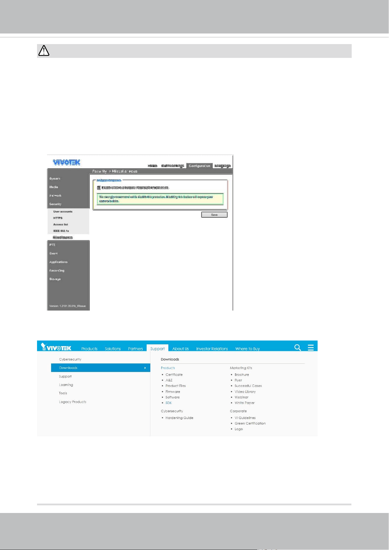
• To send URL commands in the address bar of your web browser, please remember to
disable the Cross-Site Request Forgery (CSRF) protection in Conguration > Security
> Miscellaneous.
• For up-to-date documentation of URL commands, please go to VIVOTEK’s website,
register an account with a business mail address and submit for authorization for SDK
in Support > Downloads > SDK.
• For any further technical support, please contact our technical support department.
VIVOTEK
8 - User's Manual
Symbols and Statements in this Document
i
INFORMATION: provides important messages or advices that might help prevent
inconvenient or problem situations.
NOTE: Notices provide guidance or advices that are related to the functional integrity of
the machine.
Tips: Tips are useful information that helps enhance or facilitae an installation, function,
or process.
WARNING: or IMPORTANT:: These statements indicate situations that can be
dangerous or hazardous to the machine or you.
Electrical Hazard: This statement appears when high voltage electrical hazards might
occur to an operator.
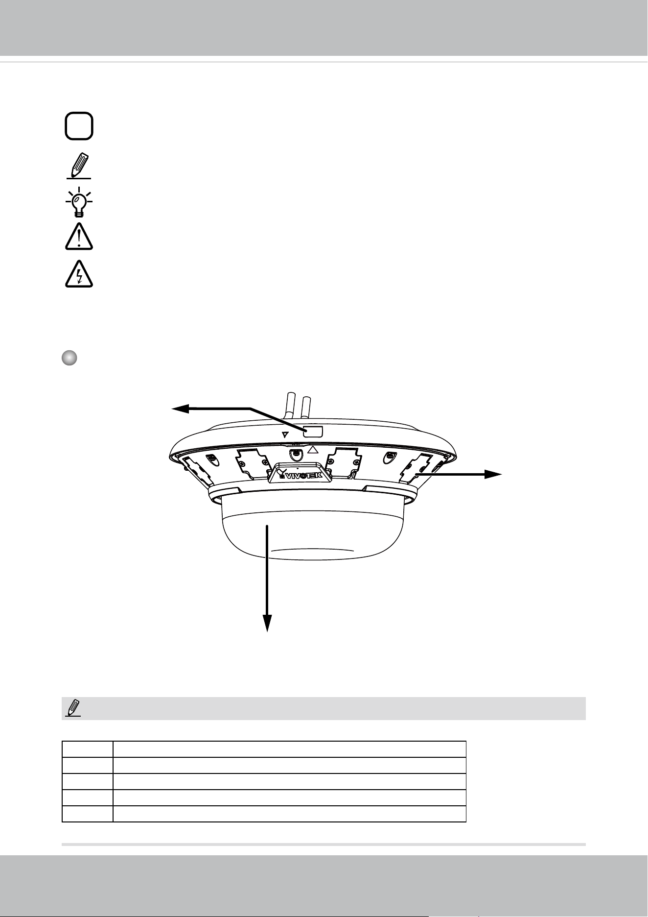
Physical Description
Outer View
Some of the sux syntax used in model naming are listed below:
E w/ heater for extreme weather
Fx Focal length w/ number
T w/ Remote focus lens
R w/ PoE repeater
H w/ High Dynamic Range functionality
NOTE:
Release button
Dome cover
IR LEDS
VIVOTEK
User's Manual - 9
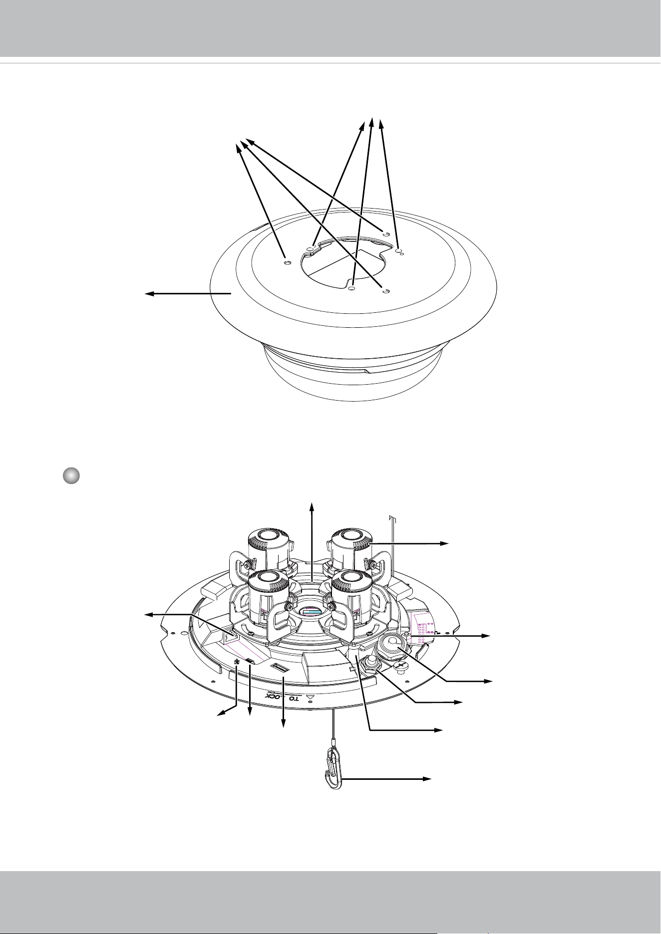
Inner View
RJ45
Ethernet port
Lens (sensor) module,
3-axis adjustable
Slide track
Microphone
contacts
J14 header
Reset button
Status LEDs
Through holes for ceiling-mount or AM-21C
Top mounting
plate
Threaded holes for AM-529
Safety tether wire
J8 header
Cable gland for Ethernet
Cable gland for I/O combo
cable
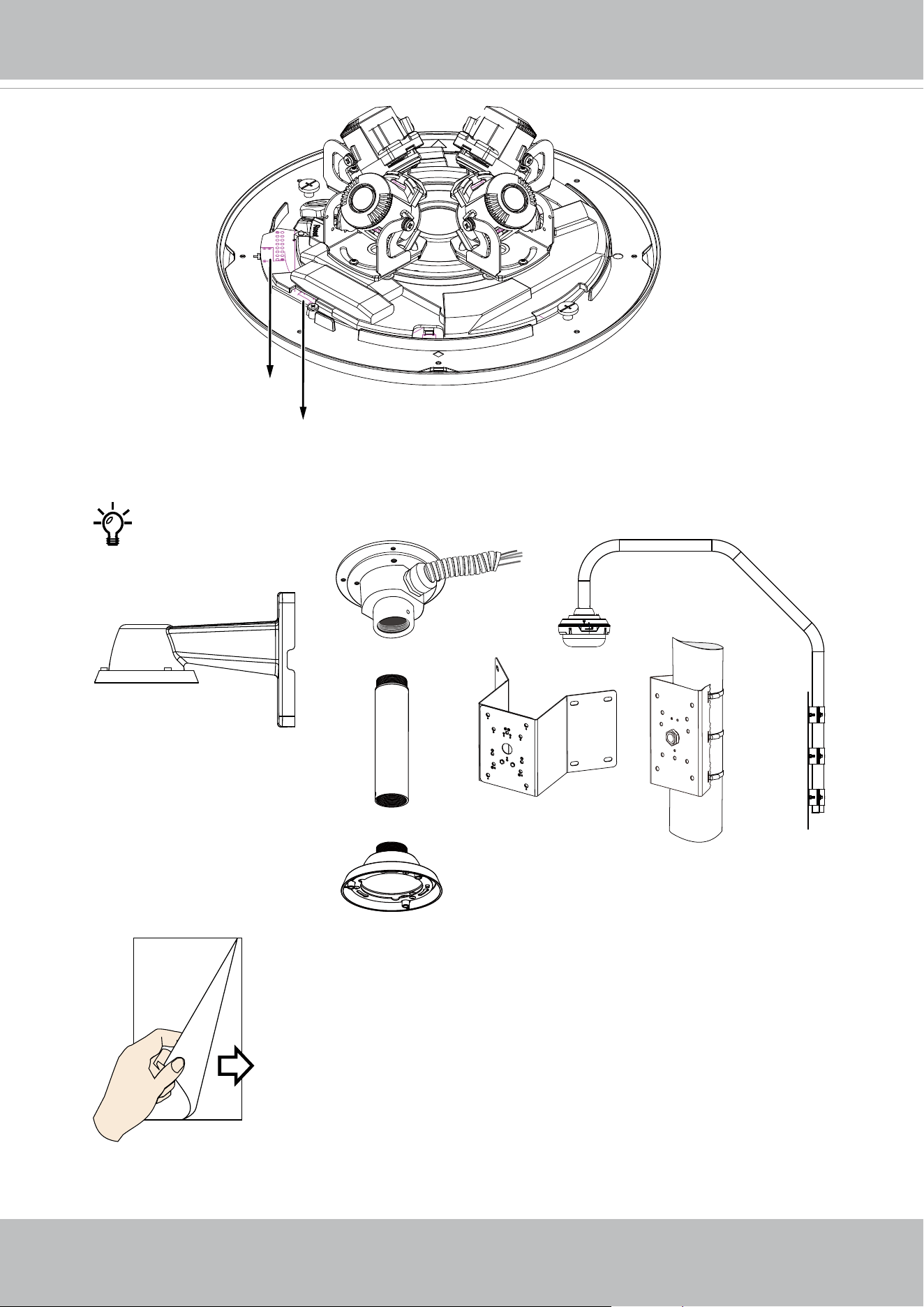
Top View
VIVOTEK
10 - User's Manual
MicroSD card slot
For the installation using optional accessories, refer to
the Optional Accessories Installation Guide
IR LED
contacts
VIVOTEK
User's Manual - 11
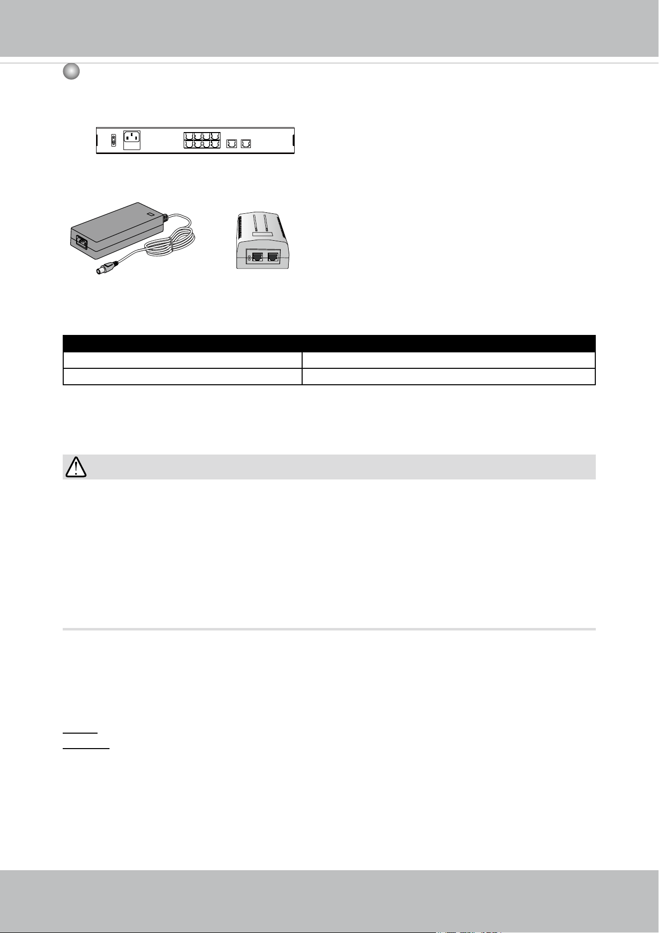
1
2
3
4
6
5
8
7
10
LAN/PoE
100~240V
AC
ON
OFF
9
GE LAN GE LAN
802.3at
24V 3.5A
PoE
injector
Power Consumption
Due to its onboard heater for operation in the low temperature environments, care
should be taken when selecting the power source for the camera. Listed below are the
requirements for powering the camera:
Use conditions Power consumption & Input
-40ºC ~ 50ºC (IR ON), 60ºC (IR OFF) PoE+: 25W (PoE Plus mid-span or switch)
-40ºC ~ 50ºC (IR ON), 60ºC (IR OFF) AC 24V input: 28W
In warmer areas that do not need a heater, a PoE+ switch can drive the camera. In areas
where temperature can drop below -20ºC, an AC 24V power adaptor is required.
• Many copper coated aluminum (CCA) and other non-standard conductors cabling
products are masqueraded as CAT5E or CAT6 cables. Please avoid using these CCA
products especially when cascading PoE cameras. It is a must to use Ethernet cables
compliant with the 3P/ETL standard.
• The camera is able to operate in low temperature environments. However, when
starting these cameras in a very low temperature condition, e.g., -40ºC, the embedded
heater may take half an hour to warm up the camera. When the temperature within the
canister reaches -10ºC, the camera automatically starts.
IMPORTANT:
Hardware Reset
The reset button is used to reset the system or restore the factory default settings.
Sometimes resetting the system can return the camera to normal operation. If the system
problems remain after reset, restore the factory settings and install again.
Reset: Press the recessed reset button. Wait for the Network Camera to reboot.
Restore: Press and hold the reset button until the status LED rapidly blinks. Note that all
settings will be restored to factory default. Upon successful restore, the status LED will
blink green and red during normal operation.
MicroSD/SDHC/SDXC Card Capacity
This network camera is compliant with SD/SDHC/SDXC 16GB / 8GB / 32GB / 64GB / ,
and up to 512 / 1024GB and other preceding standard SD cards.
VIVOTEK
12 - User's Manual
Mounting Options
1
1 3
2
4
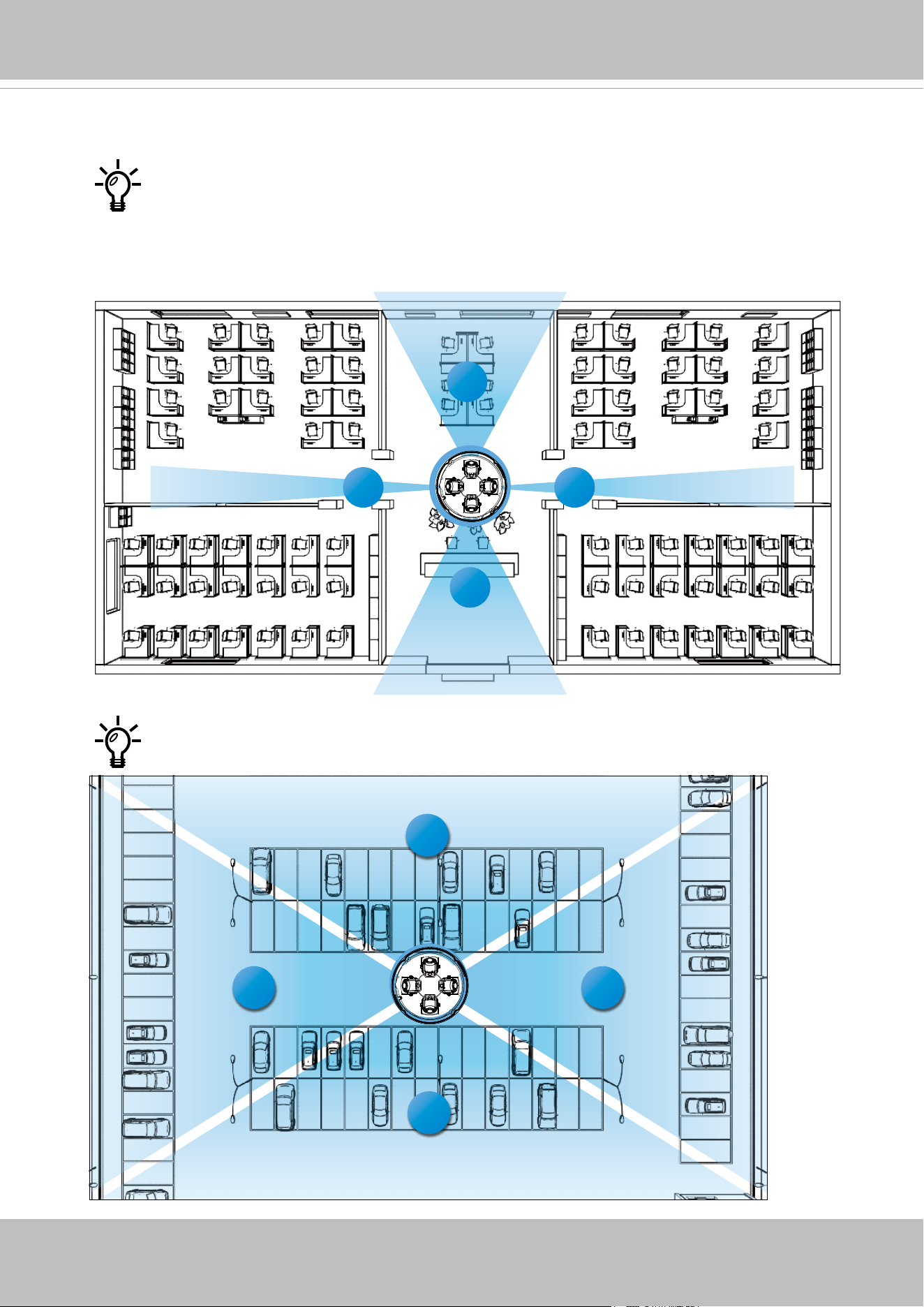
With its remote focus lenses, the lens modules can be aiming at dierent areas
at dierent distances.
Below are some sample scenarios with lenses' shooting directions adapted to
them. The Zoom function is found in Conguration > Media > Image > Focus
window.
1
2
3
4
2
VIVOTEK
User's Manual - 13
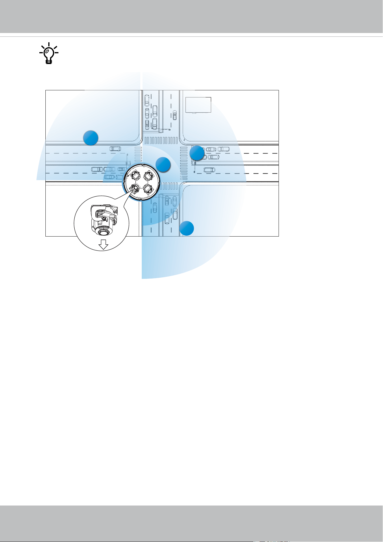
3
3
2
1
4
#1
When installed at a corner, one of its lens can be turned facing downward to
cover the area directly underneath the camera.
VIVOTEK
14 - User's Manual
Ceiling Mount
For other mounting options, please refer to the Installation Guide for Optional Accessories.
The camera can be directly installed to a wall or ceiling. Refer to the following discussion
for more on pendant mount, pole mount, and corner mount options.
See the installation details below for how to install the camera to a ceiling.
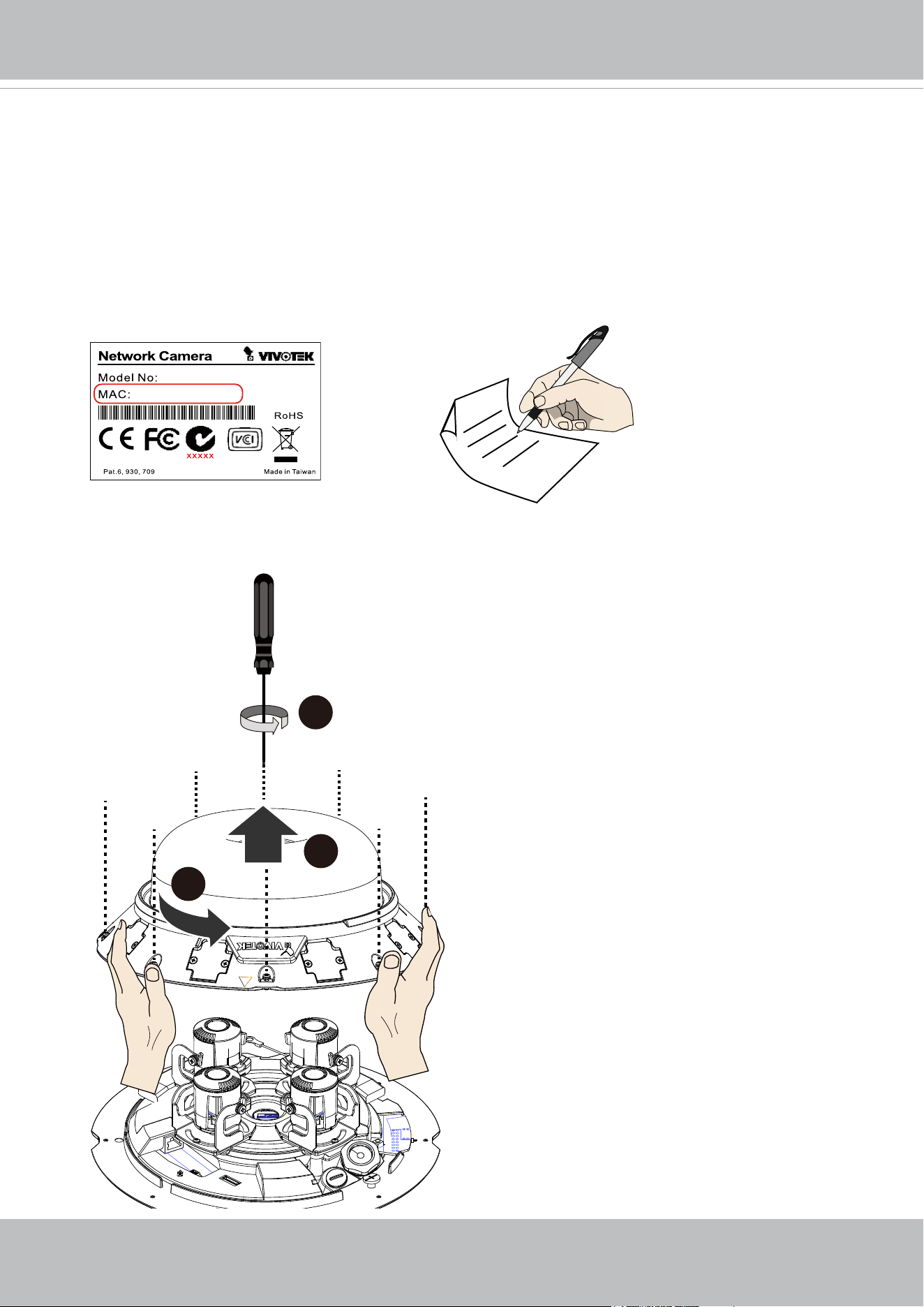
2. Open the dome cover by loosening 8 T10 anti-tamper screws. Turn slightly counter-
clockwise to remove the dome cover.
1. Jot down the camera's MAC address for later reference.
T10
x8
2
3
1
0002D10766AD
XXXXXX
VIVOTEK
User's Manual - 15
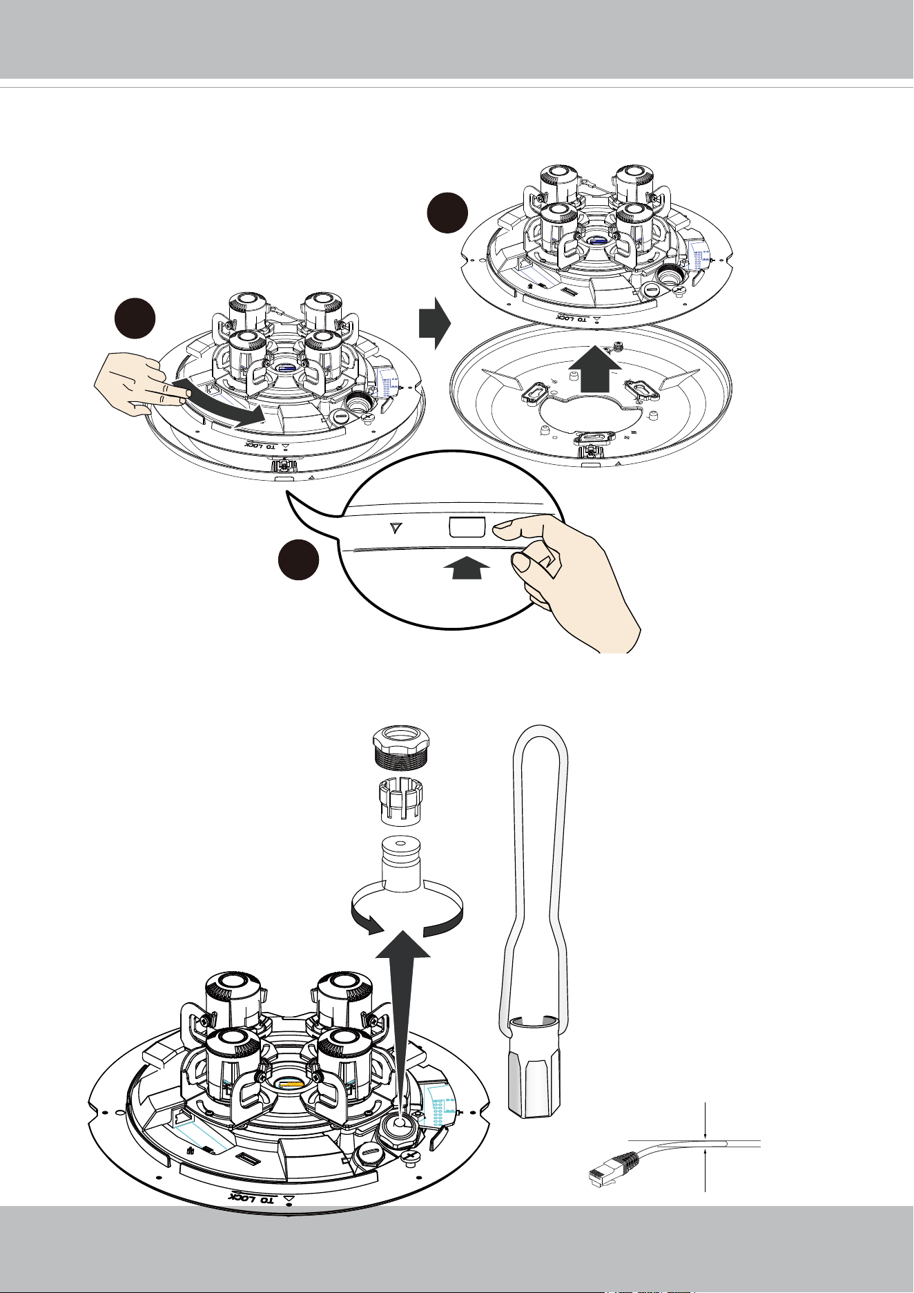
3. Remove the camera from the top mounting plate by pressing the release button. Turn
the camera counter-clockwise, and then lift it o the mounting plate.
2
3
1
4. Remove the waterproof connectors. If you do not need to route I/O wires, leave the
plastic cap in place. If you need to connect I/O wires, keep the stainless nut.
Main body
Base plate
26mm hex
socket
5~6.3mm
VIVOTEK
16 - User's Manual
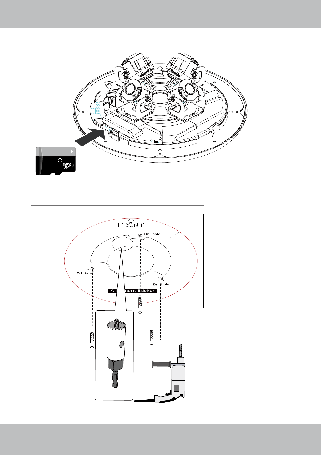
6. Attach the alignment sticker to a position you prefer. Drill screw holes and a routing hole.
64GB
10
I
1
5. Install a MicroSD card if onboard storage is preferred.
P/N : 621065800G
160mm
Cable hole
Cable hole
VIVOTEK
User's Manual - 17
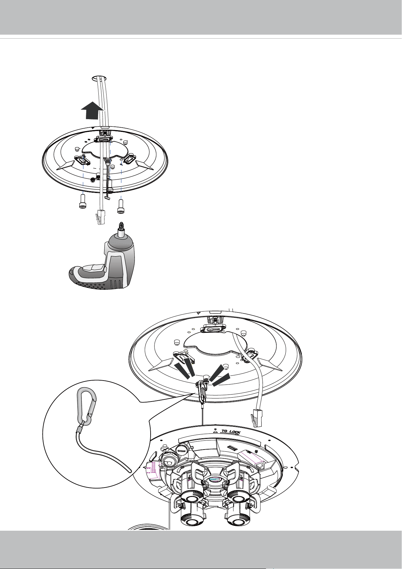
7. Route cables through the routing hole, and secure the top mounting plate to ceiling by
driving the included screws.
8. Connect the safety tether wire to the latch anchor on the mounting plate.
VIVOTEK
18 - User's Manual
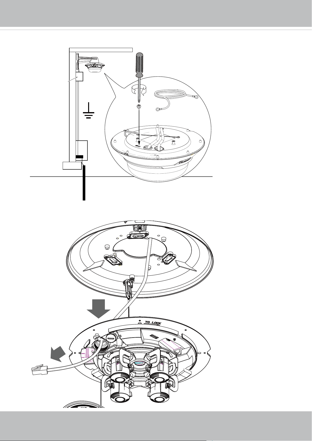
9. Connect a ground wire to the grounding screw on top of the mounting plate.
10. Pass an Ethernet cable through the cable gland through hole.
M4
20AWG
Equipment box
Equipment enclosure
Equipment grounding
VIVOTEK
User's Manual - 19
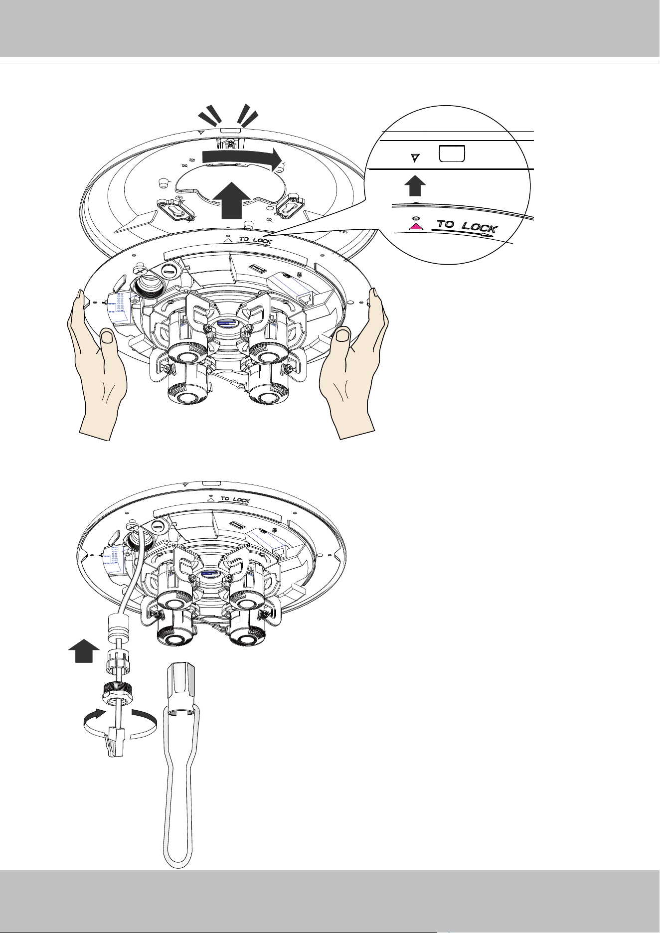
11. Secure the camera to the mounting plate by aligning and turning clock-wise. The
camera will snap into place.
26mm hex socket
12. Install and tighten the components of the waterproof connector.
VIVOTEK
20 - User's Manual
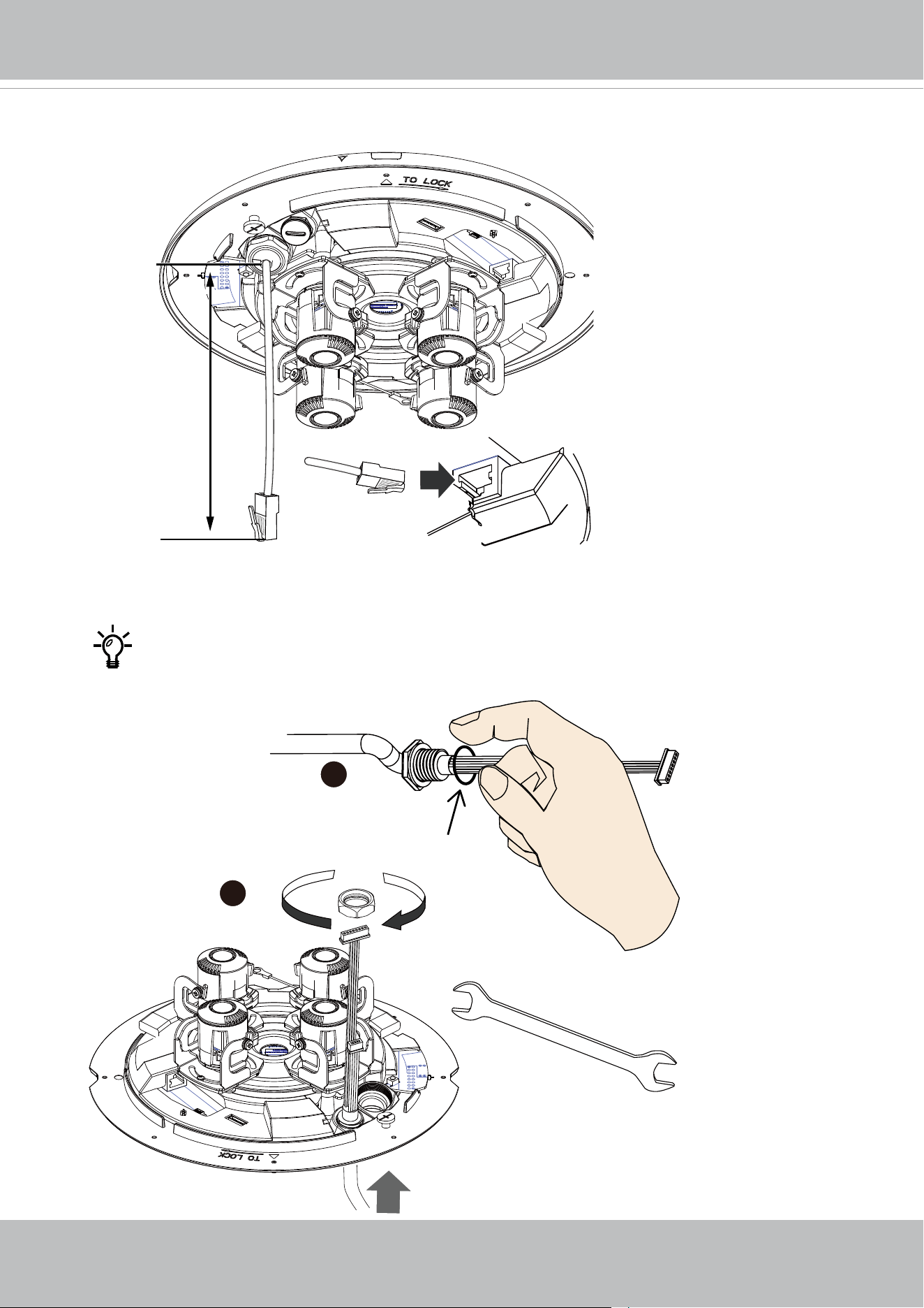
13. Leave 19 centimeters of cable length inside the camera, and connect the Ethernet
cable to the RJ45 connector.
Pass the I/O combo cable (if applied) through the routing hole, and attach a
rubber seal ring. Install the combo cable with the white headers inside the
camera, and tighten the stainless hex nut from the inside of the camera.
19cm
1
2
16mm
AO-006 I/O Combo cable
VIVOTEK
User's Manual - 21
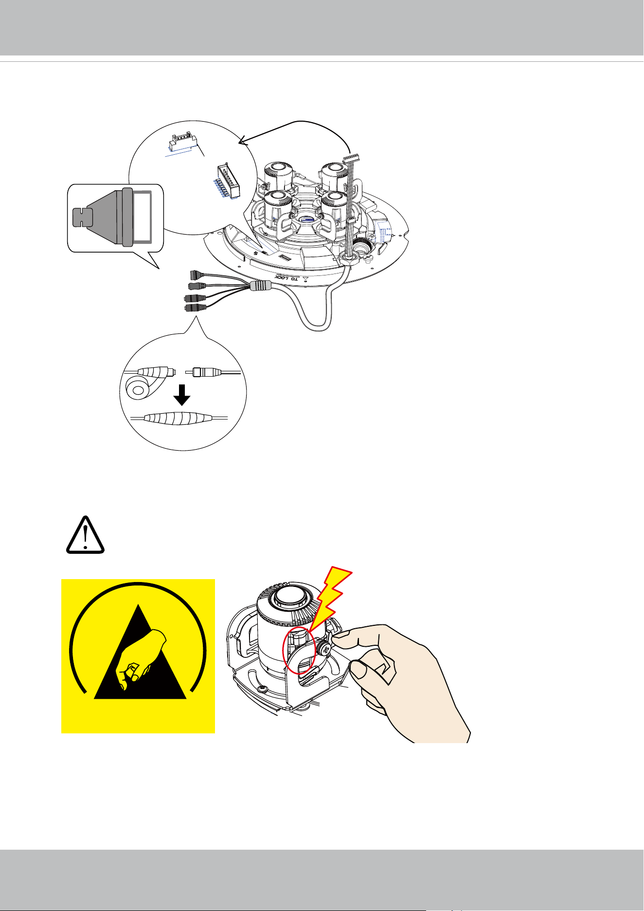
Connect the white headers to J9 and J14 heades on camera PCB board. Carefully route
the cables along the the camera base.
On the outside of the cameras, the I/O wires connection should be protected against
moisture by using putties.
GPIO
AC 24V
Ext. MIC IN
Audio Out
J9
J14
+5V
DO-
DI
GND
ESD
Mind the electrostatic damage by avoiding contact with exposed circuitry.
VIVOTEK
22 - User's Manual
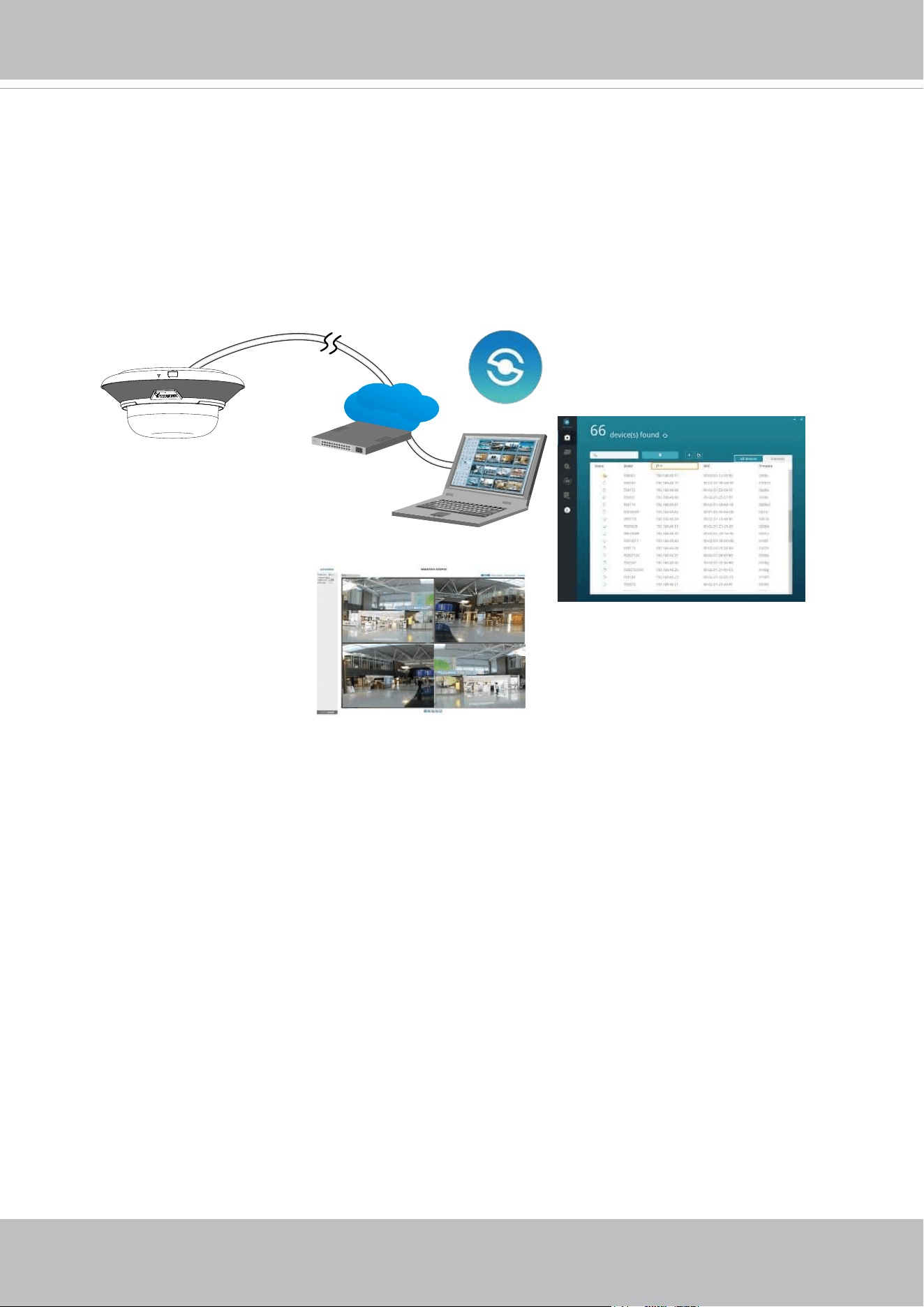
14. When the Ethernet and I/O wires connection is done and the camera is powered up, try
nd the camera using VIVOTEK's Shepherd utility.
Double-click on the camera's entry on Shepherd to open a web console to the camera.
A browser session will open.
The program will search for VIVOTEK Video Receivers, Video Servers or Network
Cameras on the same LAN.
IW2
Browser
LAN
Shepherd
VIVOTEK
User's Manual - 23
Software Installation
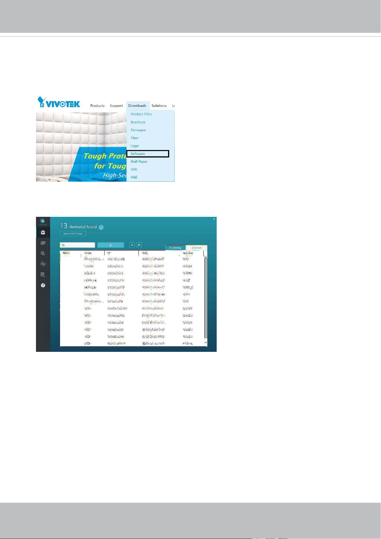
15. Install the Shepherd utility, which helps you locate and congure your Network Camera
in the local network. If your camera comes without the CD, go to VIVOTEK’s website,
and locate the utility in the Downloads > Software page.
15-1. Run the Shepherd utility.
15-2. The program will conduct an analysis of your network environment.
VIVOTEK
24 - User's Manual
0002D1730202
IB8360-W 192.168.4.151 00-02-D1-73-02-02
MA9321-EHTV
Network Camera
Model No: MA9321-EHTV
Made in Taiwan
This device complies with part 15 of the FCC rules. Operation is subject to the following two conditions:
(1)This device may not cause harmful interference, and
(2) this device must accept any interference received, including interference that may cause undesired operation.
Pat. 6,930,709
MAC:0002D1730202
R o H S
15-3. The program will search for all VIVOTEK network devices on the same LAN.
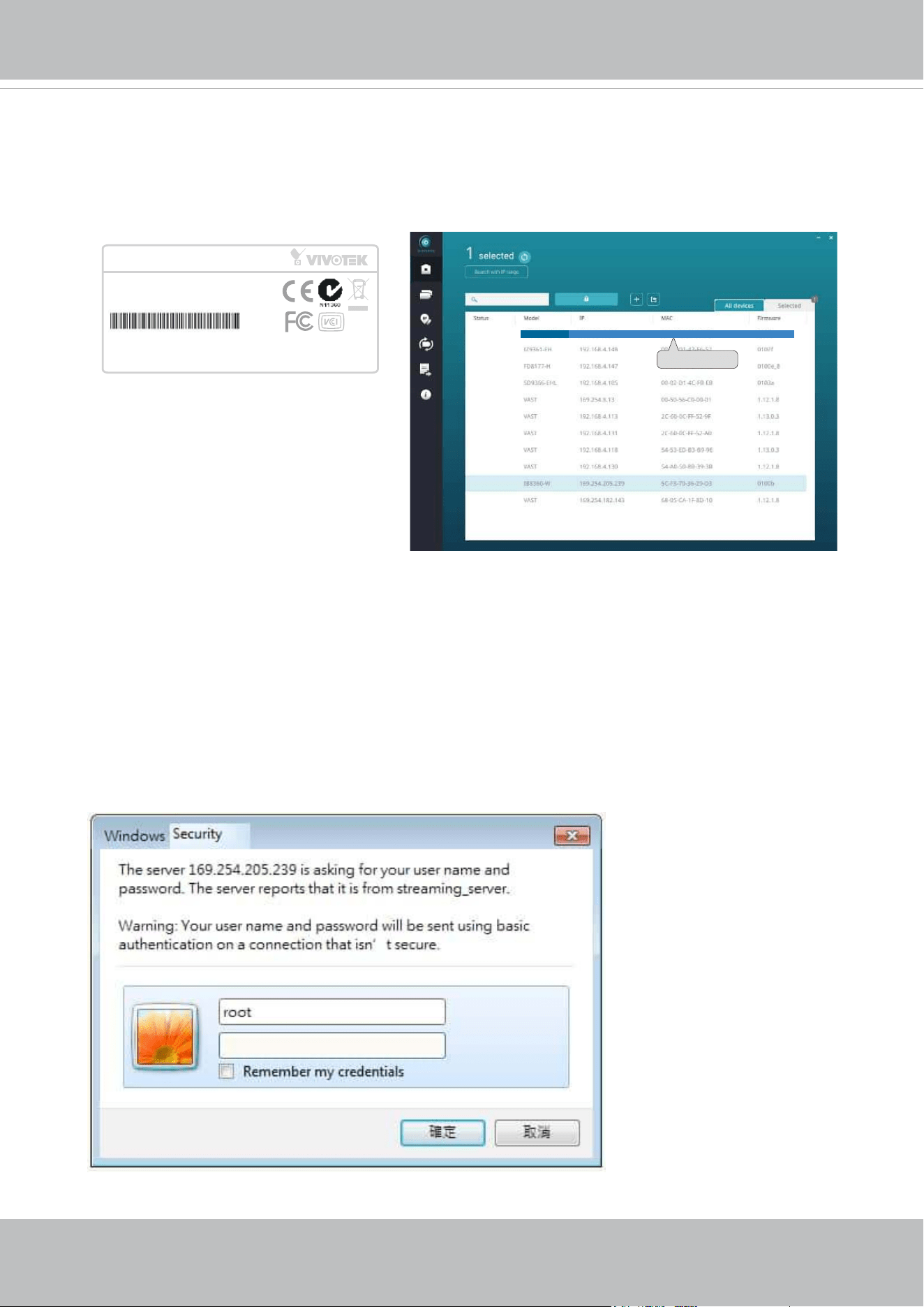
15-4. After a brief search, the installer window will prompt. Click on the MAC and model
name that matches the one printed on the product label. You can then double-click on
the address to open a management session with the Network Camera.
Forceful Password Conguration
16. The first time you log in to the camera, the firmware will prompt for a password
conguration for security concerns.
16-1. Since your camera is used for the rst time, there is no password. Enter “root” as the
user name, and nothing for the password.
VIVOTEK
User's Manual - 25
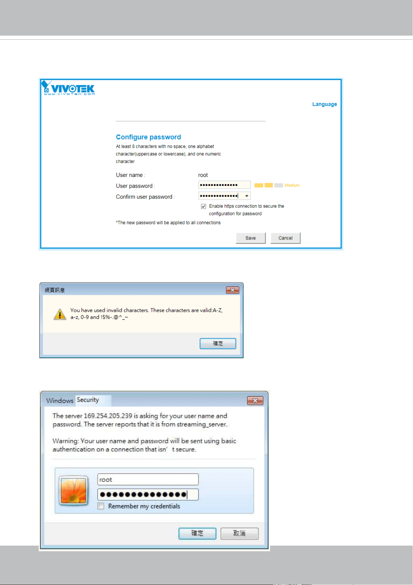
Some, but not all special ASCII characters are supported: !, $, %, -, ., @, ^, _, and ~.
You can use them in the password combination.
16-3. Another prompt will request for the password you just congured. Enter the password
and then you can start congure your camera and see the live view.
16-2. Enter the combination of alphabetic and numeric characters to fulll the password
strength requirement. The default name for the camera administrator is “root”, and can
not be changed.
VIVOTEK
26 - User's Manual
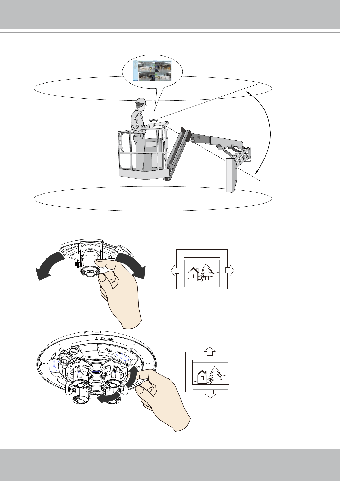
If you are not sure whether the eld of view can properly cover the area of your interest,
you can check the live view at the installation site, at a position of your estimation.
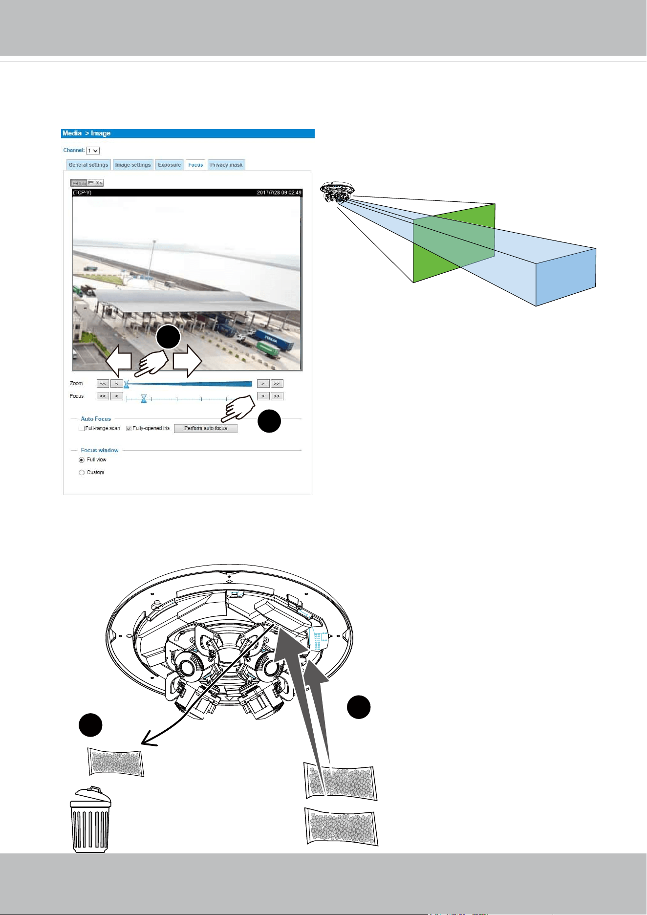
17. With a live view displayed on your laptop, you can adjust the lens shooting direction to
obtain an optimal ed of view. Check the live view to ensure the image is in focus.
VIVOTEK
User's Manual - 27
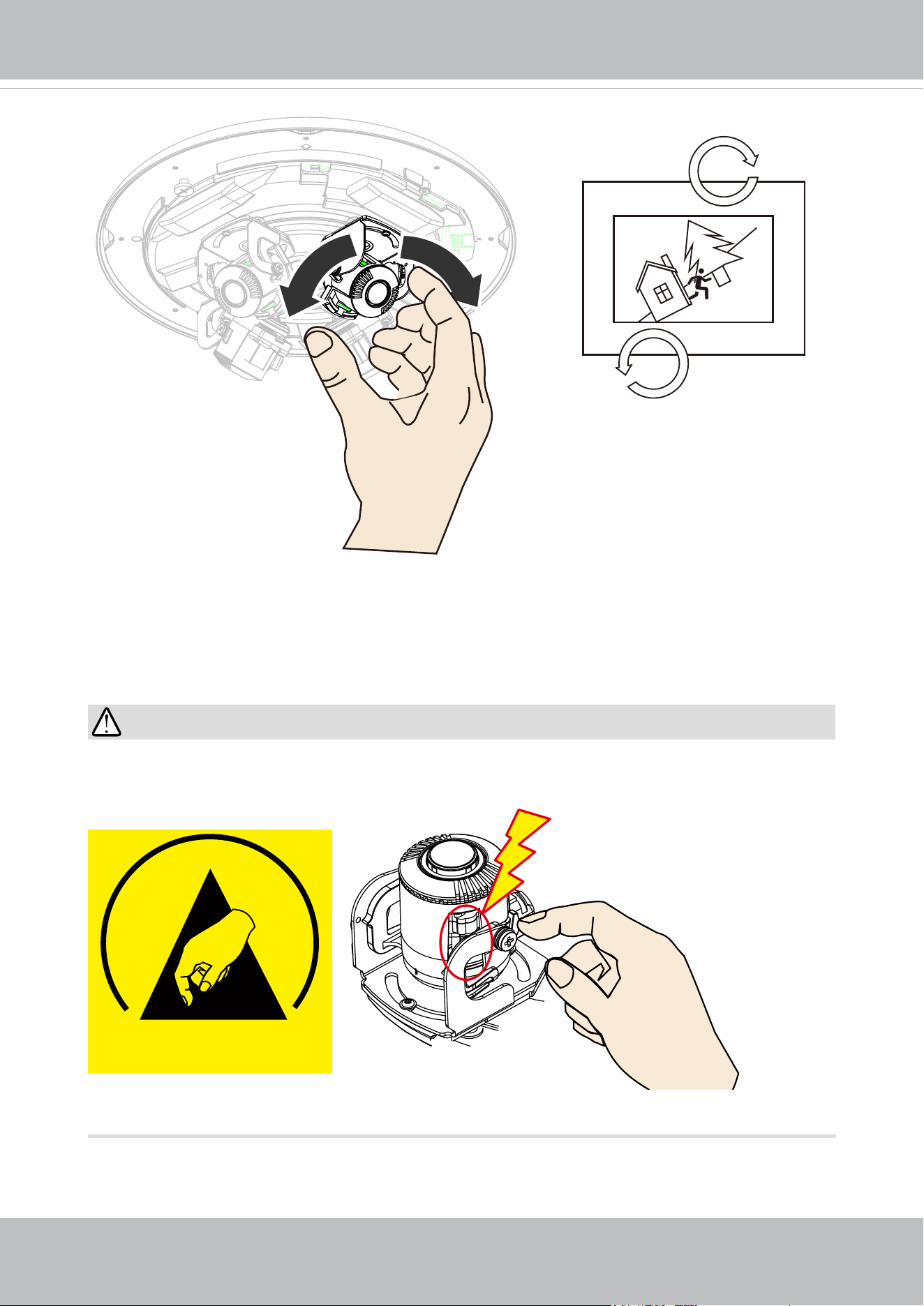
You can move a lens module from side to side, turn the lens shooting direction up or
down, or rotate the module to cover the area of your interest.
Note that you do not need any tools when changing the lens shooting direction.
When adjusting the shooting angle, please avoid touching the exposed circuit board or
ribbon cable. Static discharge can cause damages.
IMPORTANT:
ESD
VIVOTEK
28 - User's Manual
18. Perform necessary adjustments such as the image alignments on the panoramic view
from the 4 sensors. Go to Conguration > Media > Image > Focus. Zoom in on the
individual lens if necessary. The automated focus function can help you acquire the
best image.
1
2
2x Zoom
6x Zoom
19. Replace the 2 desiccant bags on the sides of the camera. This ensures the
components are free from the moisture. Replace the desiccant every time you open the
dome cover.
The zoom in/ zoom out function is performed
in the Focus window.
1
2
VIVOTEK
User's Manual - 29
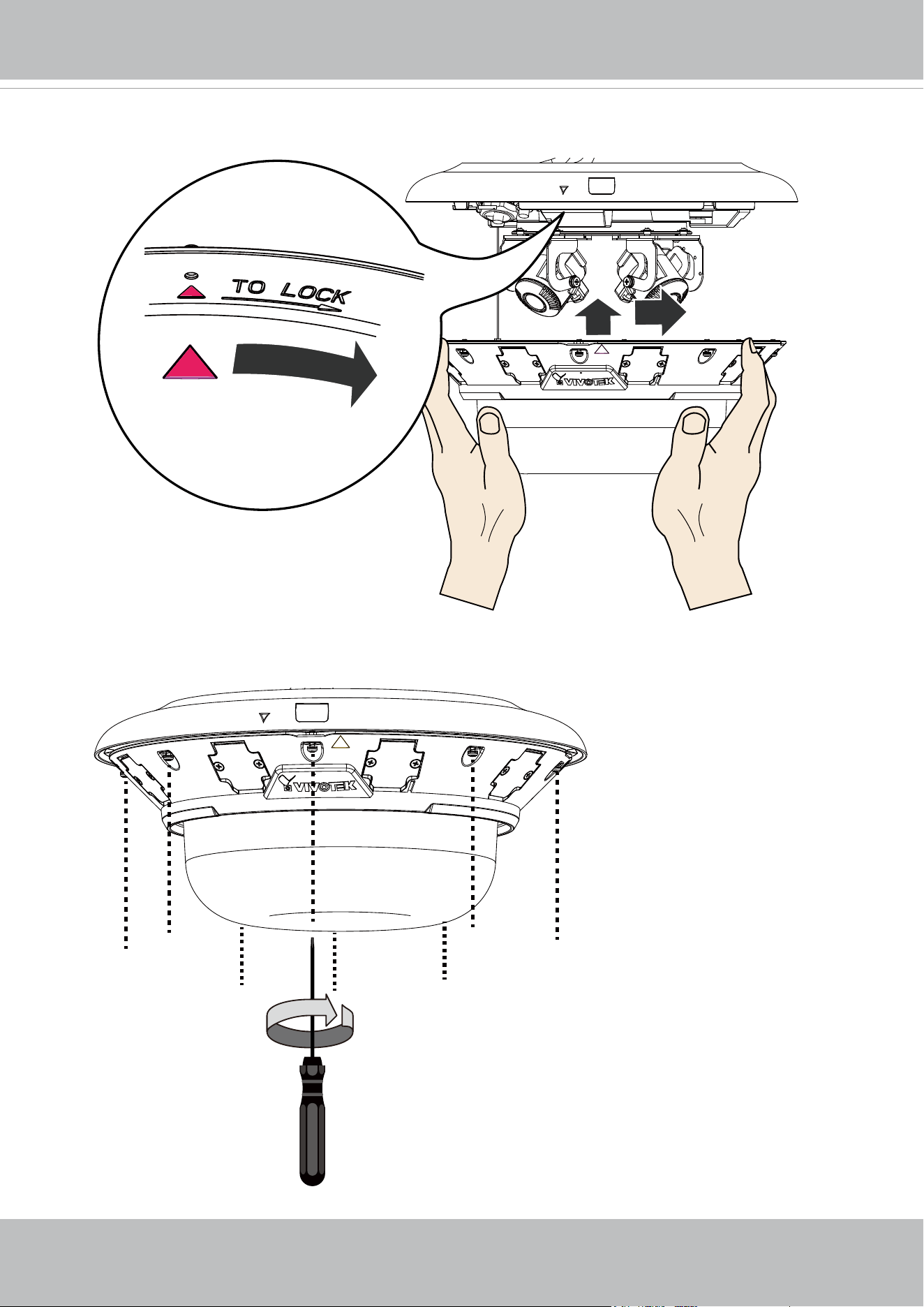
20. Aim the center of the dome cover (the center of the VIVOTEK logo) and align with the
alignment mark on the camera body. Aim and then turn clockwise.
T10
x8
21. Secure the dome cover by fastening the T10 anti-tamper screws. You may need to
carefully route the safety tether wire aside.
VIVOTEK
30 - User's Manual
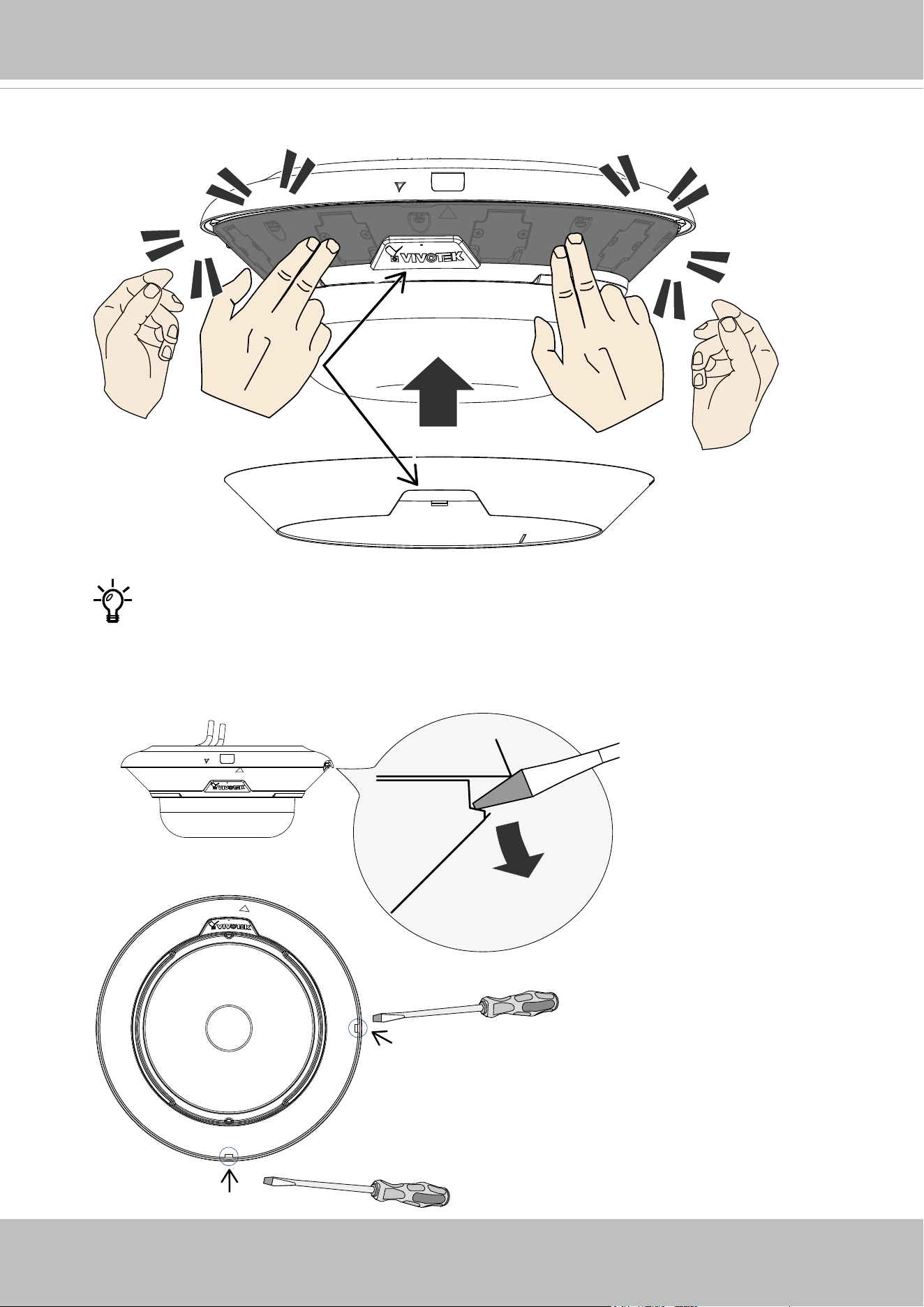
22. Install the black cover for the IR lights by pressing up rmly to the groove. Press on all
sides until the cover is snapped into place. Match the indent with VIVOTEK logo.
If you need to open the dome cover, you need to remove the IR cover rst. Use
a medium size at-blade screwdriver as a lever. Find the small access holes on
the side and the rear of the IR cover. Use the screwdriver to slowly yet rmly lever
down on the edge of the cover. You need to perform this action on both of the
access points
VIVOTEK
User's Manual - 31
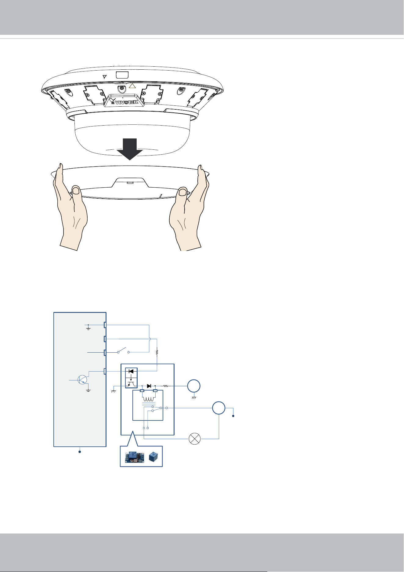
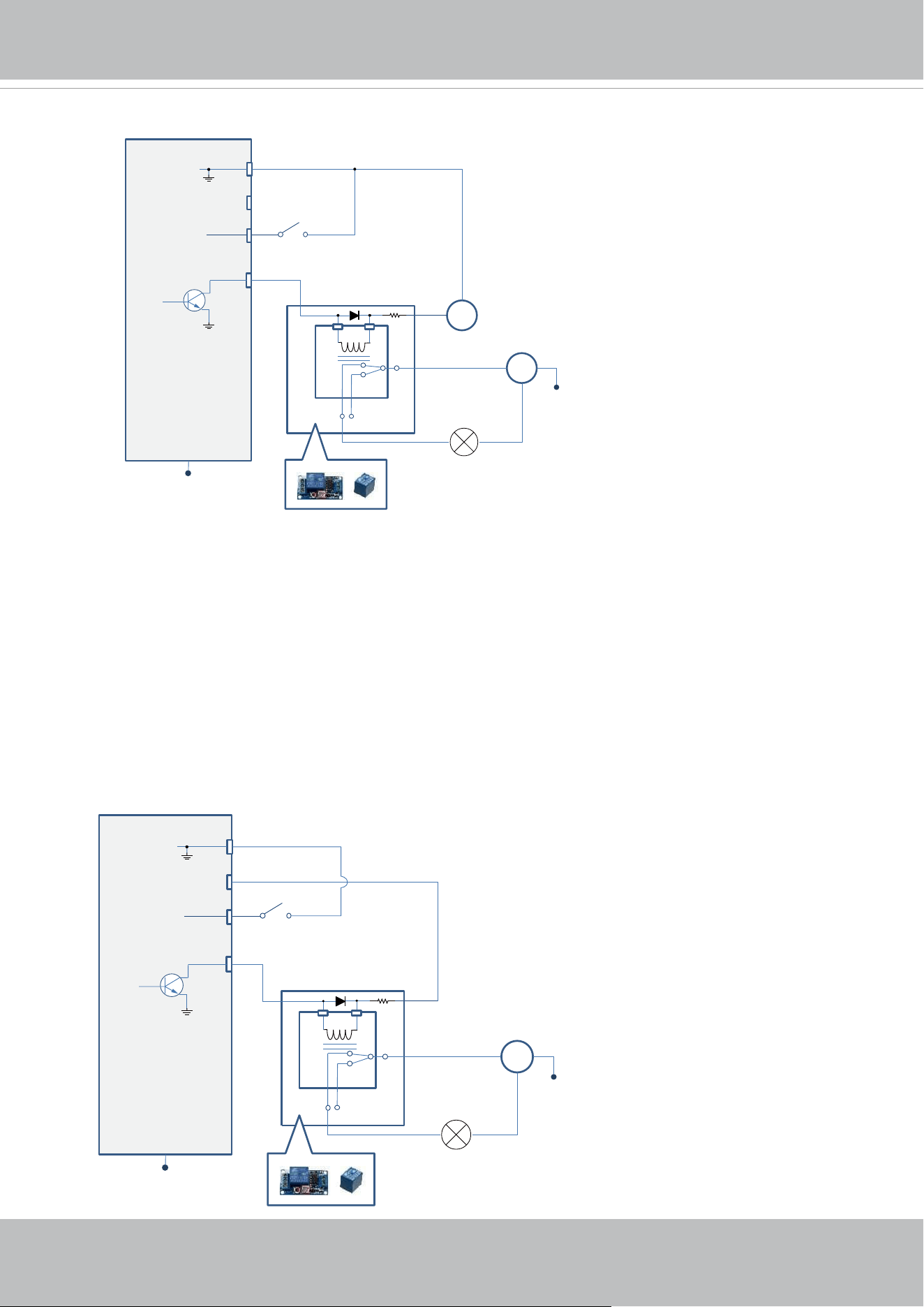
DI/DO Diagram
DI-
DO+
DI+
DO-
Switch
External Device
External DC power
Dry contact with external DC power source to supply a relay. Dry contact is the safest connecon
to protect devices.
NC
NO
Relay
Photo
Coupler
DC
DC 0V
DC 0V
External AC power
with Protected Eart
h
AC
PE
PE
The IR cover should then be removed.
VIVOTEK
32 - User's Manual
DI-
DO+
DI+
DO-
Switch
External Device
External DC power
Wet contact with external DC power source to supply a relay.
NC
NO
Relay
DC
External AC power
with Protected Earth
AC
PE
PE
DC 0V
1. The DO+ pin provides a 5V output voltage, and the max. load is 50mA.
2. The max. voltage for DO- pins is 30VDC (External power).
In order to control AC devices, the above diagram can be taken in consideration. The
diagram uses a relay to control the ON/OFF condition of the AC device.
3. An external relay can be triggered by using DO+ or by an external power source,
depending on the type of relay you use.
4. In case of using an individual relay (instead of using a relay module), for protection
against voltage or current spikes, a transient voltage suppression diode must be
connected in parallel with the inductive load.
DI-
DO+
DI+
DO-
Switch
External Device
Dry contact and using camera’s DO+ to supply a relay.
NC
NO
Relay
AC
External AC power
with Protected Eart
h
PE
PE
VIVOTEK
User's Manual - 33
Network Deployment
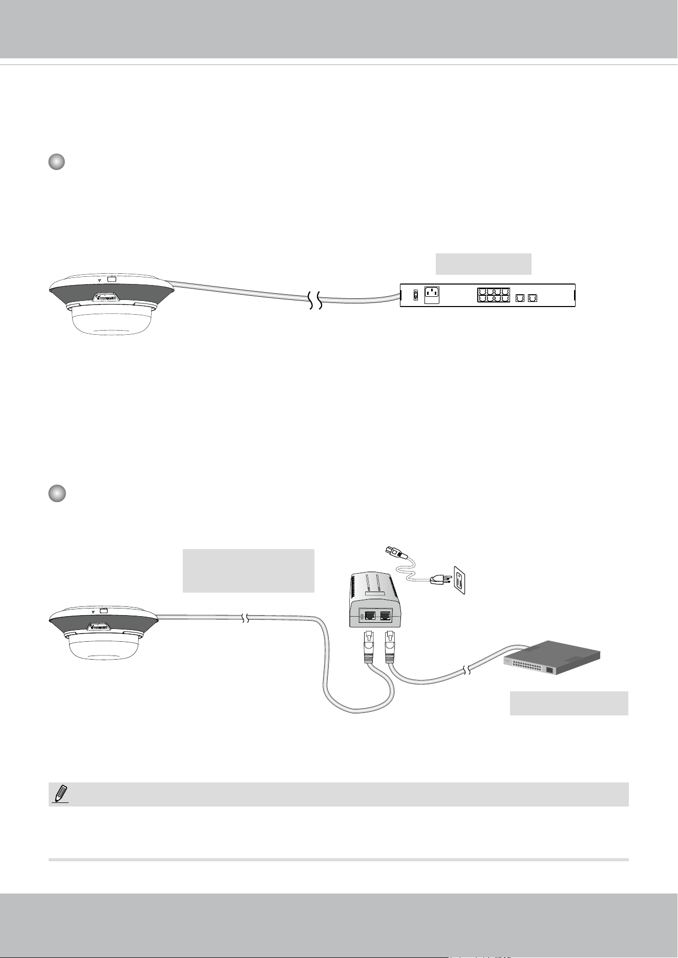
General Connection (PoE)
When using a PoE-enabled switch
The Network Camera is PoE-compliant, allowing transmission of power and data via a sin-
gle Ethernet cable. Follow the below illustration to connect the Network Camera to a PoE-
enabled switch via Ethernet cable.
1
2
3
4
6
5
8
7
10
LAN/PoE
100~240V
AC
ON
OFF
9
GE LAN GE LAN
PoE Switch
When using a non-PoE switch
Use a 802.3at PoE power injector (optional) to connect between the Network Camera and a
non-PoE switch.
Non-PoE Switch
PoE Power Injector
(optional)
NOTE:
1. The camera is only to be connected to PoE networks without routing to outside plants.
2. For PoE connection, use only UL listed I.T.E. with PoE output.
802.3at
Depending on the requirements of your installation site, select an appropriate power source,
such as an 802.3at PoE (30W) for operating temperature higher than -10ºC. For extremely low
temperature, you will need a power source higher than 21W, such as 24V AC.
If using an 802.3at PoE as the power source, the lowest operating temperature is -20ºC.
VIVOTEK
34 - User's Manual
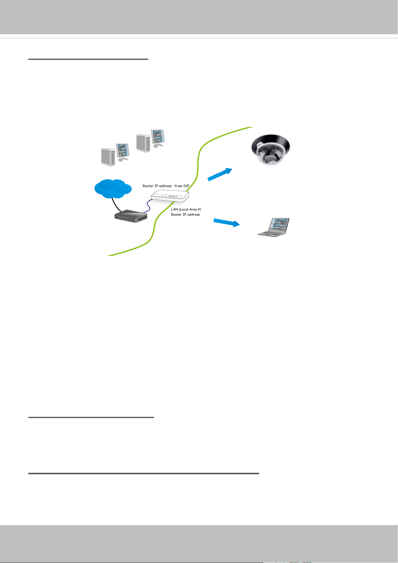
Internet connection via a router
Before setting up the Network Camera over the Internet, make sure you have a router and follow
the steps below.
1. Connect your Network Camera behind a router, the Internet environment is illustrated below.
Regarding how to obtain your IP address, please refer to Software Installation on page 23 for
details.
IP address : 192.168.0.3
Subnet mask : 255.255.255.0
Default router : 192.168.0.1
IP address : 192.168.0.2
Subnet mask : 255.255.255.0
Default router : 192.168.0.1
LAN (Local Area Network)
Router IP address : 192.168.0.1
WAN (Wide Area Network )
Router IP address : from ISP
Cable or DSL Modem
POWER
COLLISION
LINK
RECEIVE
PARTITION
1
2
3
4
5
Internet
2. In this case, if the Local Area Network (LAN) IP address of your Network Camera is
192.168.0.3, please forward the following ports for the Network Camera on the router.
■ HTTP port: default is 80
■ RTSP port: default is 554
■ RTP port for video: default is 5556
■ RTCP port for video: default is 5557
If you have changed the port numbers on the Network page, please open the ports
accordingly on your router. For information on how to forward ports on the router, please refer
to your router’s user’s manual.
3. Find out the public IP address of your router provided by your ISP (Internet Service Provider).
Use the public IP and the secondary HTTP port to access the Network Camera from the
Internet. Please refer to Network Type on page 98 for details.
Internet connection with static IP
Choose this connection type if you are required to use a static IP for the Network Camera.
Please refer to LAN setting on page 97 for details.
Internet connection via PPPoE (Point-to-Point over Ethernet)
Choose this connection type if you are connected to the Internet via a DSL Line. Please refer to
PPPoE on page 98 for details.
VIVOTEK
User's Manual - 35
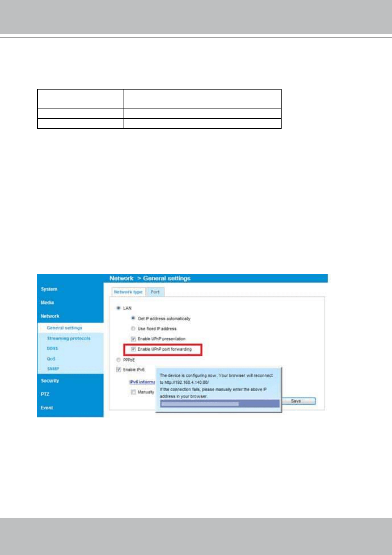
Congure the router, virtual server or rewall, so that the router can forward any data com-
ing into a precongured port number to a network camera on the private network, and
allow data from the camera to be transmitted to the outside of the network over the same
path.
From Forward to
122.146.57.120:8000 192.168.2.10:80
122.146.57.120:8001 192.168.2.11:80
... ...
When properly congured, you can access a camera behind the router using the HTTP
request such as follows: http://122.146.57.120:8000
If you change the port numbers on the Network conguration page, please open the ports
accordingly on your router. For example, you can open a management session with your
router to congure access through the router to the camera within your local network.
Please consult your network administrator for router conguration if you have troubles with
the conguration.
For more information with network conguration options (such as that of streaming ports),
please refer to Conguration > Network Settings. VIVOTEK also provides the automatic
port forwarding feature as an NAT traversal function with the precondition that your router
must support the UPnP port forwarding feature.
VIVOTEK
36 - User's Manual
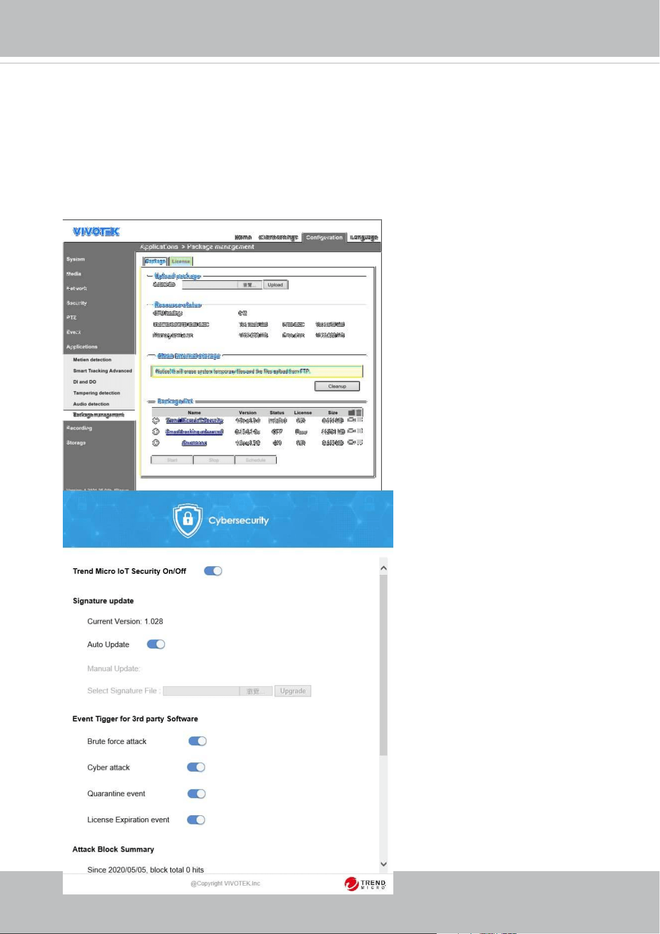
Cybersecurity
Once you open the web console, enter Configuration > Applications > Package
management, and click on Trend Micro IoT Security. Turn on the protection to fend o cyber
attacks.
In here, you can let the camera automatically update the virus codes or manually update the
virus codes.

VIVOTEK
User's Manual - 37
Ready to Use
1. A browser session with the Network Camera should prompt as shown below.
2. You should be able to see live video from your camera. You may also install the 32-channel
recording software from the software CD in a deployment consisting of multiple cameras. For
its installation details, please refer to its related documents.
3. Click to expand the Video stream menu to select to display individual sensor.
VIVOTEK
38 - User's Manual
Accessing the Network Camera
This chapter explains how to access the Network Camera through web browsers, RTSP players,
3GPP-compatible mobile devices, and VIVOTEK recording software.
Using Web Browsers
Use the Shepherd utility to access the Network Cameras on LAN.
If your network environment is not a LAN, follow these steps to access the Netwotk Camera:
1. Launch your web browser (e.g., Microsoft
®
Internet Explorer or Mozilla Firefox).
2. Enter the IP address of the Network Camera in the address eld. Press Enter.
3. Live video will be displayed in your web browser.
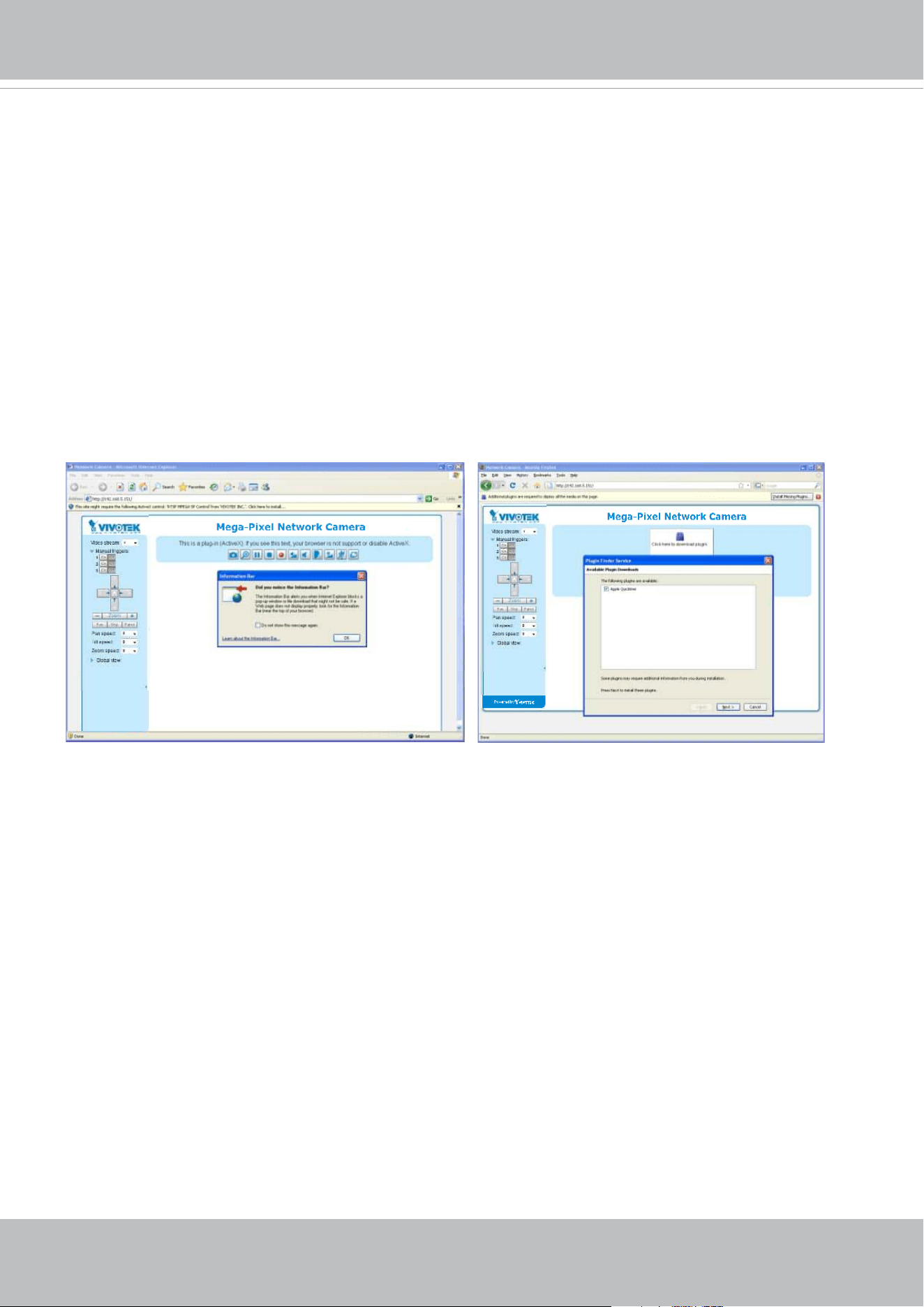
4. If it is the rst time installing the VIVOTEK network camera, an information bar will prompt as
shown below. Follow the instructions to install the required plug-in on your computer.
VIVOTEK
User's Manual - 39
► By default, the Network Camera is not password-protected. To prevent unauthorized access,
it is highly recommended to set a password for the Network Camera.
For more information about how to enable password protection, please refer to Security on
page 118.
► If you see a dialog box indicating that your security settings prohibit running ActiveX
®
Controls, please enable the ActiveX
®
Controls for your browser.
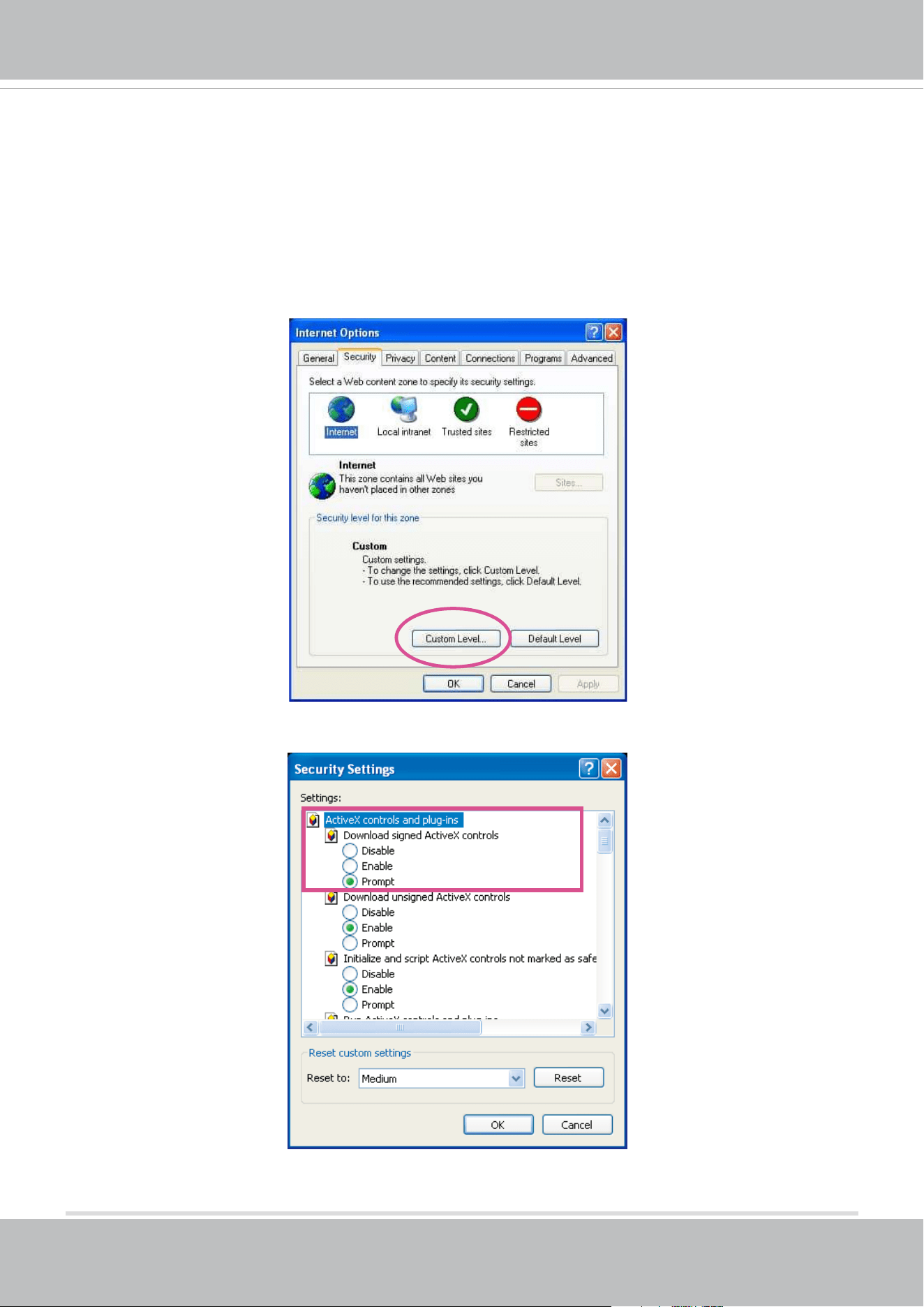
1. Choose Tools > Internet Options > Security > Custom Level.
2. Look for Download signed ActiveX
®
controls; select Enable or Prompt. Click OK.
3. Refresh your web browser, then install the ActiveX
®
control. Follow the instructions to
complete installation.
VIVOTEK
40 - User's Manual
•
Currently the Network Camera utilizes a 32-bit ActiveX plugin. You CAN NOT open a
management/view session with the camera using a 64-bit IE browser.
•
If you encounter this problem, try execute the Iexplore.exe program from C:\Windows\
SysWOW64. A 32-bit version of IE browser will be installed.
•
On Windows 7, the 32-bit explorer browser can be accessed from here:
C:\Program Files (x86)\Internet Explorer\iexplore.exe
•
If you open a web session from the Shepherd utility, a 32-bit IE browser will be
opened.
IMPORTANT:
1. The onscreen Java control can malfunction under the following situations: A PC con-
nects to dierent cameras that are using the same IP address (or the same camera
running dierent rmware versions). Removing your browser cookies will solve this
problem.
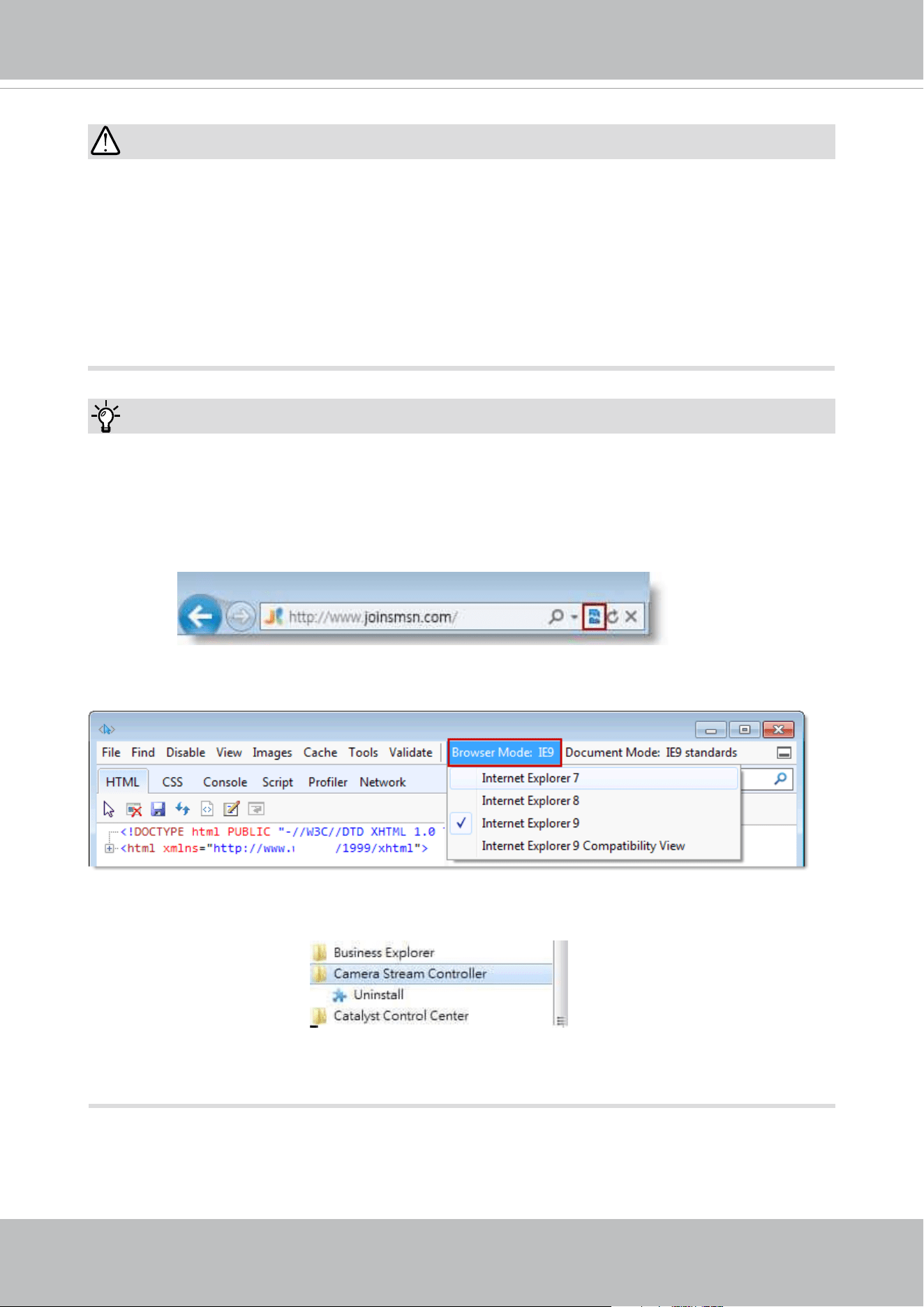
2. If you encounter problems with displaying the conguration menus or UI items, try dis-
able the Compatibility View on IE8 or IE9.
You may also press the F12 key to open the developer tools utility, and then change the
Browser Mode to the genuine IE8 or IE9 mode.
Tips:
• In the event of plug-in compatibility issues, you may try to uninstall the plug-in that was
previously installed.
VIVOTEK
User's Manual - 41
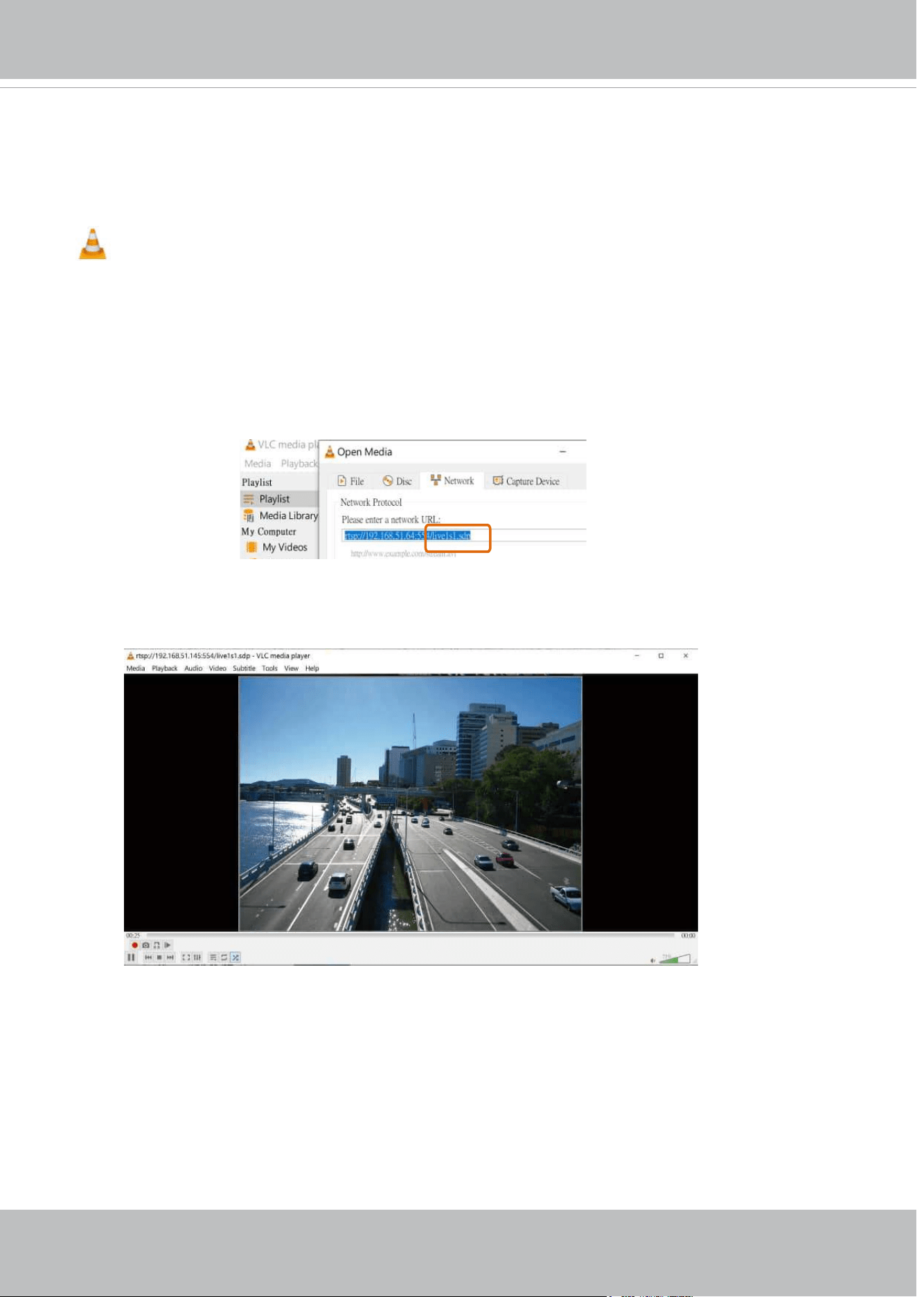
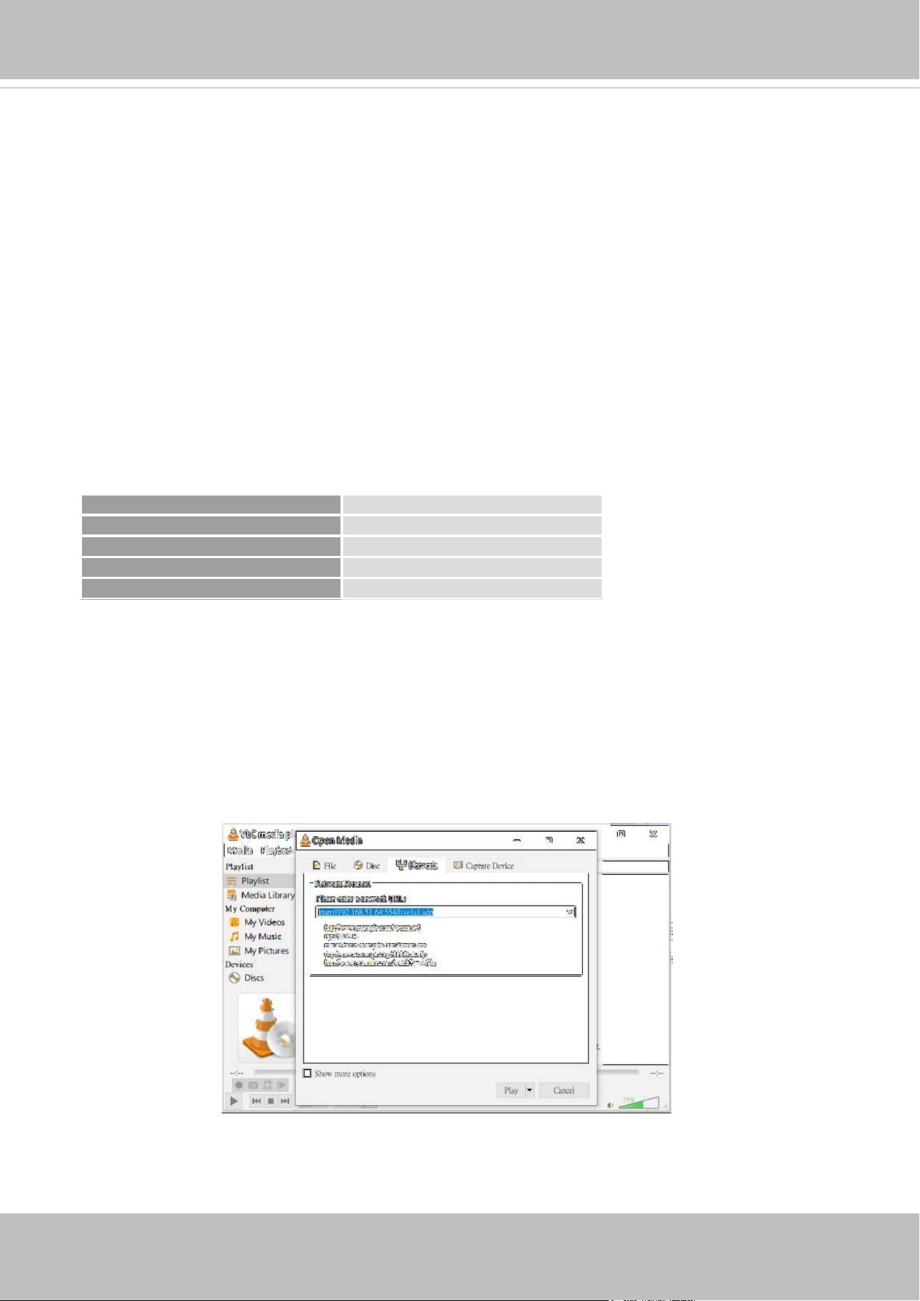
Using RTSP Players
To view the streaming media using RTSP players, you can use one of the following players that
support RTSP streaming.
VLC media player
VLC media player
mpegable Player
pvPlayer
As most ISPs and players only allow RTSP streaming through port number 554, please set the
RTSP port to 554. For more information, please refer to RTSP Streaming on page 106.
For example:
4. The live video will be displayed in your player.
For more information on how to configure the RTSP access name, please refer to RTSP
Streaming on page 106 for details.
1. Launch the RTSP player.
2. Choose File > Open URL. A URL dialog box will pop up.
3. The address format is rtsp://<ip address>:<rtsp port>/<RTSP streaming access name for
stream1 or stream2>
rtsp://192.168.5.151:554/live1s1.sdp
VIVOTEK
42 - User's Manual
Using 3GPP-compatible Mobile Devices
To view the streaming media through 3GPP-compatible mobile devices, make sure the Network
Camera can be accessed over the Internet. For more information on how to set up the Network
Camera over the Internet, please refer to Setup the Network Camera over the Internet on page
34.
To utilize this feature, please check the following settings on your Network Camera:
1. Because most players on 3GPP mobile phones do not support RTSP authentication, make
sure the authentication mode of RTSP streaming is set to disable.
For more information, please refer to RTSP Streaming on page 106.
2. As the the bandwidth on 3G networks is limited, you will not be able to use a large video size.
Please set the video streaming parameters as listed below.
For more information,
please refer to Stream settings on page 84.
Video Mode H.264
Frame size 176 x 144
Maximum frame rate 5 fps
Intra frame period 1S
Video quality (Constant bit rate) 40kbps
3. As most ISPs and players only allow RTSP streaming through port number 554, please set
the RTSP port to 554. For more information, please refer to RTSP Streaming on page 106.
4. Launch the player on the 3GPP-compatible mobile devices (e.g., VLC player).
5. Type the following URL commands into the player.
The address format is rtsp://<public ip address of your camera>:<rtsp port>/<RTSP streaming
access name for stream # with small frame size and frame rate>.
For example:
You can configure Stream #2 into the suggested stream settings as listed above for live
viewing on a mobile device.
VIVOTEK
User's Manual - 43
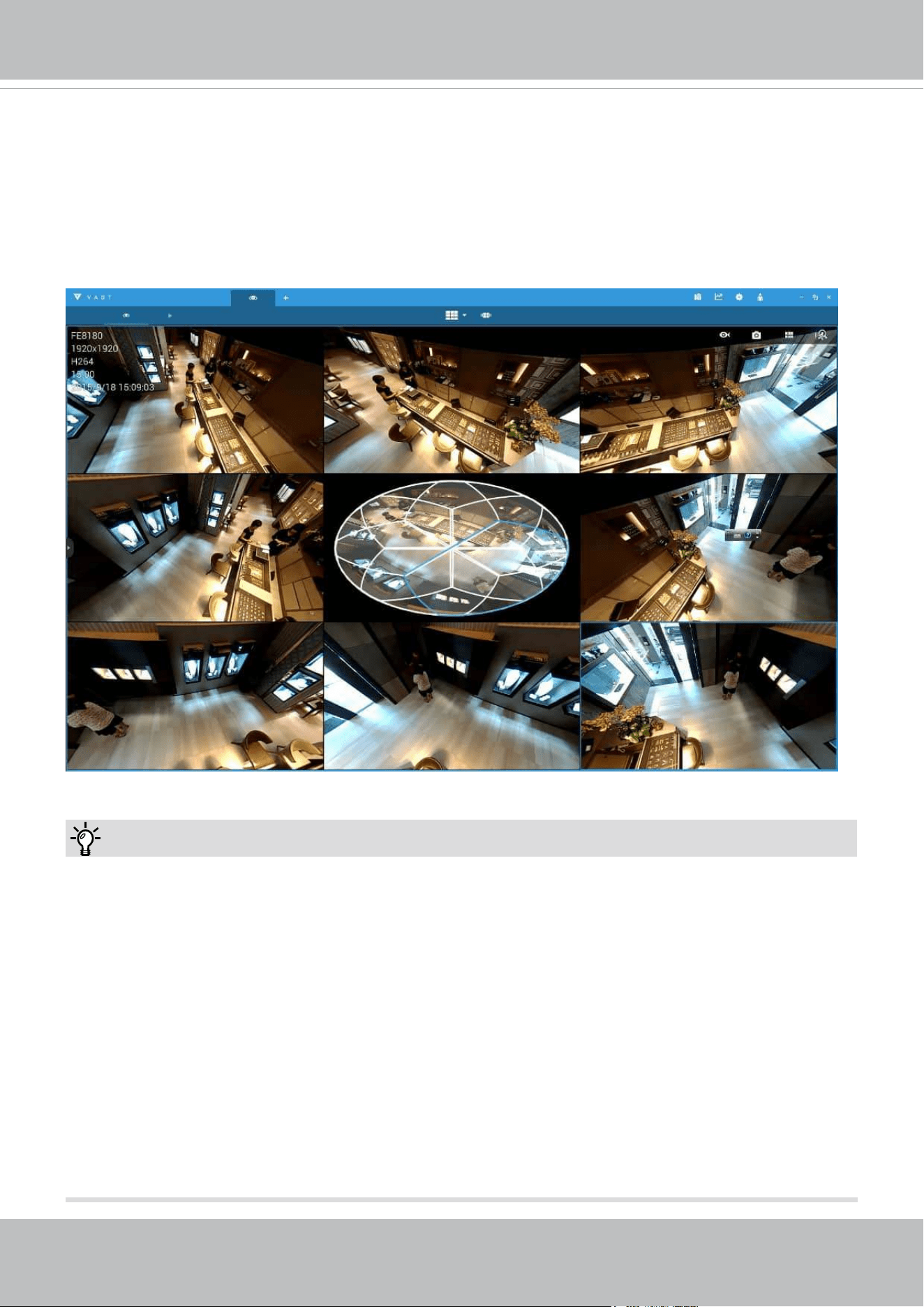
Using VIVOTEK Recording Software
The product software CD also contains a VAST recording software, allowing simultaneous
monitoring and video recording for multiple Network Cameras. Please install the recording
software; then launch the program to add the Network Camera to the Channel list. For detailed
information about how to use the recording software, please refer to the user’s manual of the
software or download it from
http://www.vivotek.com.
Tips:
1. If you encounter problems with displaying live view or the onscreen plug-in control, you may try
to remove the plug-ins that might have been installed on your computer. Remove the following
folder: C:\Program Files (x86)\Camera Stream Controller\.
2. If you forget the root (administrator) password for the camera, you can restore the camera
defaults by pressing the reset button for longer than 5 seconds.
3. If DHCP is enabled in your network, and the camera cannot be accessed, run the Shepherd
utility to search the network. If the camera has been congured with xed IP that does not
comply with your local network, you may see its default IP 169.254.x.x. If you still cannot nd
the camera, you can restore the camera to its factory defaults.
4. If you change your network parameters, e.g., added a connection to a LAN card, re-start the
Shepherd utility.
VIVOTEK
44 - User's Manual
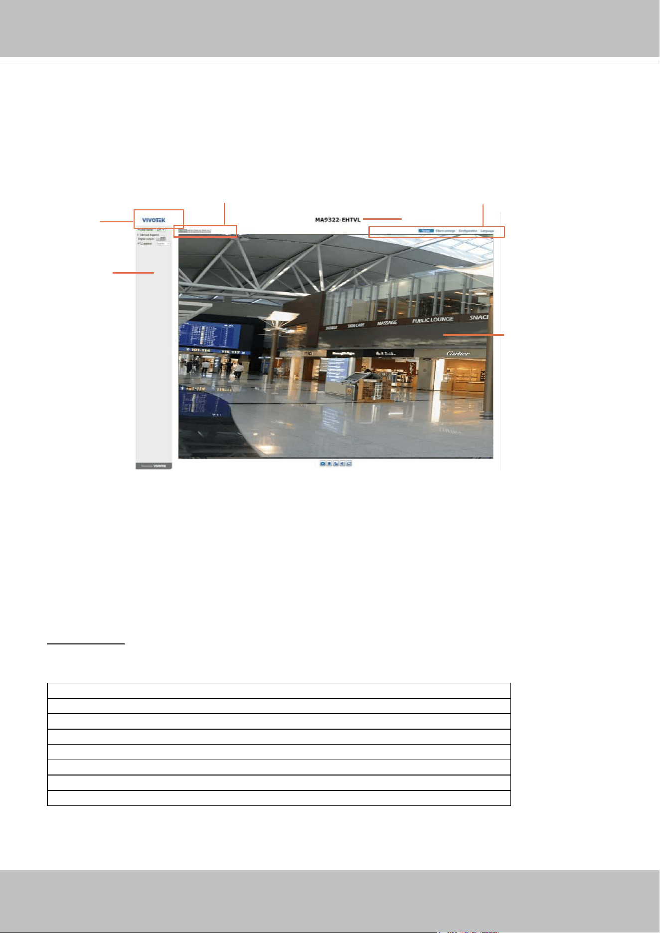
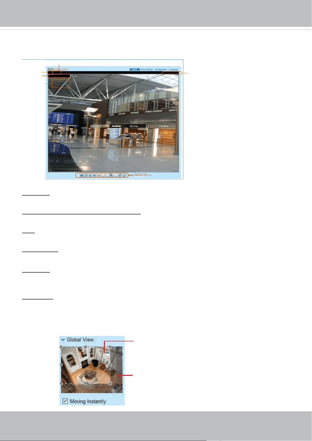
Main Page
This chapter explains the layout of the main page. It is composed of the following sections:
VIVOTEK INC. Logo, Host Name, Camera Control Area, Configuration Area, Menu, and Live
Video Window.
VIVOTEK INC.
Logo
Camera Control
Area
Configuration Area
Host Name
Resize Buttons
Live View Window
VIVOTEK INC. Logo
Click this logo to visit the VIVOTEK website.
Host Name
The host name can be customized to t your needs. The name can be changed especially there are many
cameras in your surveillance deployment. For more information, please refer to System on page 56.
Camera Control Area
Stream prole: This Network Camera supports multiple streams simultaneously. You can select any of
them for live viewing. Each prole corresponds to one video stream for one sensor (CH, channel). There
are 4 sensors, and each sensor (CH) supports 3 dierent video streams.
CH1 Max view - Stream 1 (congurable, default 2688 x 1920)
CH1 Recording - Stream 2 (congurable, default 1280 x 960)
CH2 Max view- Stream 1 (congurable, default 2688 x 1920)
CH2 Recording - Stream 2 (congurable, default 1280 x 960)
CH3 Max view- Stream 1 (congurable, default 2688 x 1920)
CH3 Recording - Stream 2 (congurable, default 1280 x 960)
CH4 Max view - Stream 1 (congurable, default 2688 x 1920)
CH4 Recording - Stream 2 (congurable, default 1280 x 960)
VIVOTEK
User's Manual - 45
Conguration Area
Client Settings: Click this button to access the client setting page. For more information, please refer to
Client Settings on page 50.
Conguration: Click this button to access the conguration page of the Network Camera. It is suggested
that a password be applied to the Network Camera so that only the administrator can configure the
Network Camera. For more information, please refer to Conguration on page 55.
Language: Click this button to choose a language for the user interface. Language options are available
in: English, Deutsch, Español, Français, Italiano,
日本語
, Português,
簡体中文
,
繁體中文,
and
Ρусский
.
Please note that you can also change a language on the Conguration page; please refer to page 55.
Hide Button
You can click the hide button to hide or display the control panel.
Resize Buttons
:
Click the Auto button, the video cell will resize automatically to t the monitor.
Click 100% is to display the original homepage size.
Click 50% is to resize the homepage to 50% of its original size.
Click 25% is to resize the homepage to 25% of its original size.
Manual Trigger: Click to enable/disable an event trigger manually. Please congure an event setting on
the Application page before you enable this function. A total of 3 event conguration can be congured.
For more information about event setting, please refer to page 136. If you want to hide this item on
the homepage, please go to Configuration> System > Homepage Layout > General settings >
Customized button to deselect the “show manual trigger button” checkbox.
Digital Output: Click to turn the digital output device on or o.
For more information about multiple streams, please refer to page 71 for detailed information.
VIVOTEK
46 - User's Manual
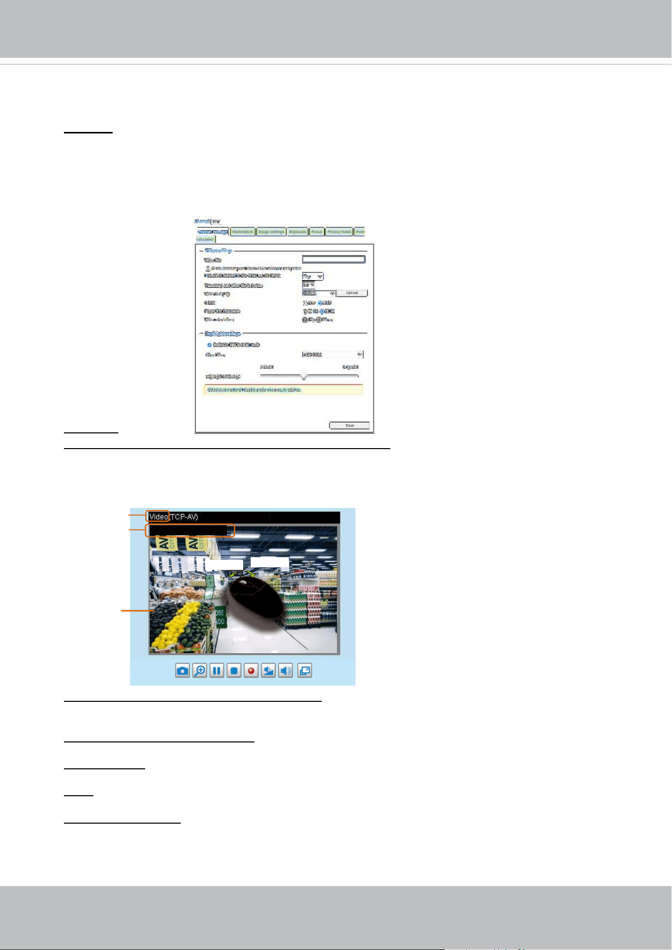
Video Control Buttons
Video 17:08:56 2019/10/11
Title and Time
Video (TPC-AV)
H.264 Protocol and Media Options
Video Title
x4.0
Zoom Indicator
2019/10/11 17:08:56
Time
Video Title: The video title can be congured. For more information, please refer to Video Settings on
page 70.
H.264 or H. 265 Protocol and Media Options: The transmission protocol and media options for H.264
video streaming. For further conguration, please refer to Client Settings on page 50.
Time: Display the current time. For further conguration, please refer to Media > Image > Genral settings
on page 70.
Title and Time: The video title and time can be stamped on the streaming video. For further conguration,
please refer to Media > Image > General settings on page 75.
Global View: Click on this item to display the Global View window. The Global View window contains a
full view image (the largest frame size of the captured video) and a oating frame (the viewing region of
the current video stream). The oating frame allows users to control the e-PTZ function (Electronic Pan/
Tilt/Zoom). For more information about e-PTZ operation, please refer to E-PTZ Operation on page 133.
For more information about how to set up the viewing region of the current video stream, please refer to
page 133.
The viewing region of
the curruent video
stream
The largest frame size
PTZ Panel: This Network Camera supports “digital“ (e-PTZ) pan/tilt/zoom control, which allows roaming
a smaller view frame within a large view frame. Please refer to PTZ settiings on page 133 for detailed
information.
Live Video Window
■ The following window is displayed when the video mode is set to H.265 or H.264:
PTZ panel and Global view are available
when displaying the Recording prole.
VIVOTEK
User's Manual - 47
Video Control Buttons: Depending on the Network Camera model and Network Camera conguration,
some buttons may not be available.
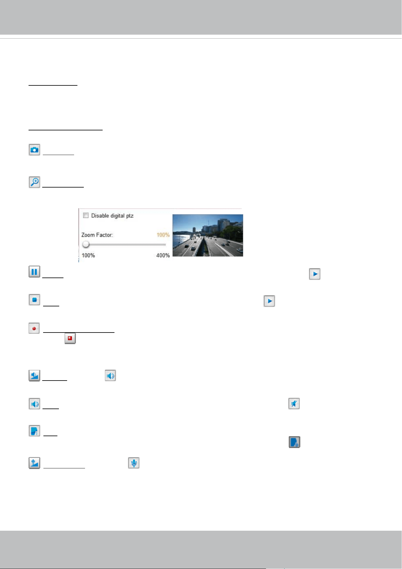
Snapshot: Click this button to capture and save still images. The captured images will be displayed
in a pop-up window. Right-click the image and choose Save Picture As to save it in JPEG (*.jpg) or BMP
(*.bmp) format.
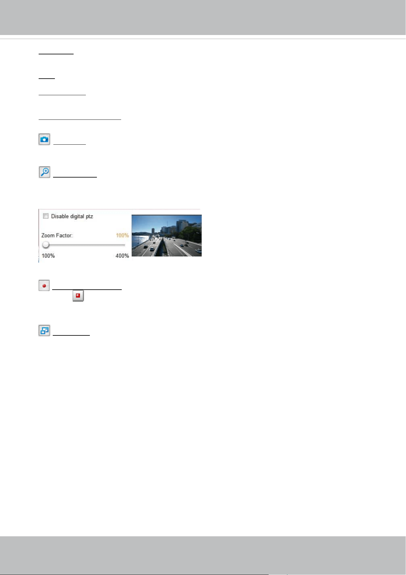
Digital Zoom: Click and uncheck “Disable digital zoom” to enable the zoom operation. The navigation
screen indicates the part of the image being magnied. To control the zoom level, drag the slider bar. To
move to a dierent area you want to magnify, drag the navigation screen.
Pause: Pause the transmission of the streaming media. The button becomes the Resume button
after clicking the Pause button.
Stop: Stop the transmission of the streaming media. Click the Resume button to continue
transmission.
Start MP4 Recording: Click this button to record video clips in MP4 file format to your computer.
Press the
Stop MP4 Recording button to end recording. When you exit the web browser, video
recording stops accordingly. To specify the storage destination and le name, please refer to MP4 Saving
Options on page 51 for details.
Volume: When the Mute function is not activated, move the slider bar to adjust the volume on the
local computer.
Mute: Turn o the volume on the local computer. The button becomes the Audio On button after
clicking the Mute button.
Talk: Click this button to talk to people around the Network Camera. Audio will project from
the external speaker connected to the Network Camera. Click this button
again to end talking
transmission.
Mic Volume: When the Mute function is not activated, move the slider bar to adjust the
microphone volume on the local computer.
Note that the PTZ buttons on the panel are not operational unless you are showing only a portion of the
full image. If the live view window is displaying the full view, the PTZ buttons are not functional.
Move Instantly: If you choose to display only a portion of the total eld of view, say, zoomed in on the
current eld of view using the Global View setting, you can select or deselect the “Move Instantly” option.
Move Instantly means the process of moving from one portion to another is not shown on screen.
VIVOTEK
48 - User's Manual
NOTE:
1. For a megapixel camera, it is recommended to use monitors of the 24" size or larger, which
are capable of 1600x1200 or better resolutions.
2. Below are the defaults for Audio settings:
For cameras with built-in microphone: Not Muted.
For cameras without built-in microphone: Muted.
To receive audio input from an external microphone, you may need to enable the audio input
from Media > Audio. Refer to page 94 for more information.
Mute: Turn o the Mic volume on the local computer. The button becomes the Mic On button
after clicking the Mute button.
Full Screen: Click this button to switch to full screen mode. Press the “Esc” key to switch back to normal
mode.
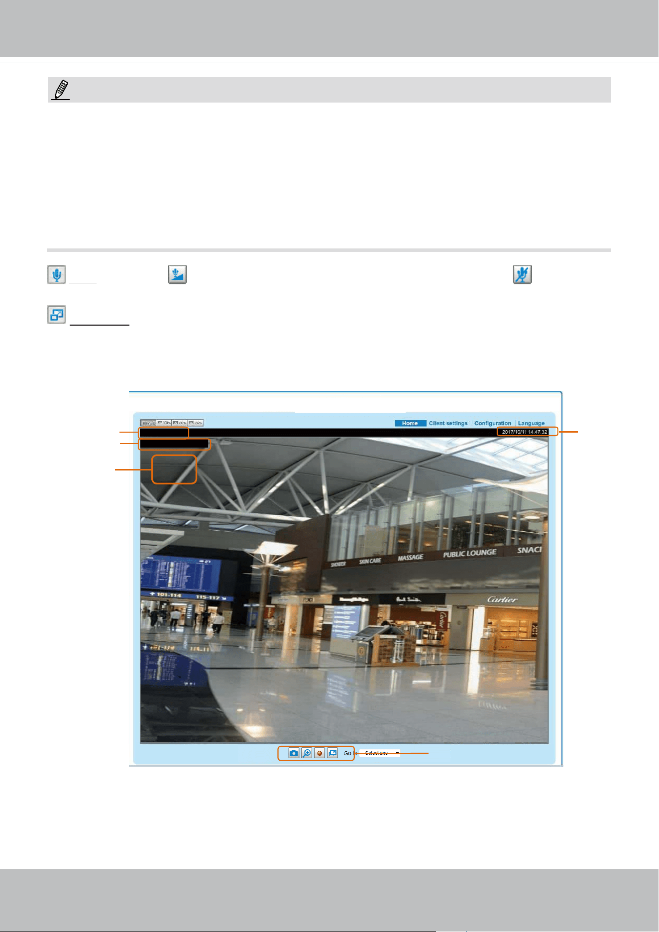
■ The following window is displayed when the video mode is set to MJPEG:
Time
Video Control Buttons
Video 14:47:32 2017/10/11
Title and Time
x4.0Zoom Indicator
Video (HTTP-V)
Video Title
VIVOTEK
User's Manual - 49
Start MP4 Recording: Click this button to record video clips in MP4 le format to your computer.
Press the
Stop MP4 Recording button to end recording. When you exit the web browser, video
recording stops accordingly. To specify the storage destination and le name, please refer to MP4
Saving Options on page 51 for details.
Full Screen: Click this button to switch to full screen mode. Press the “Esc” key to switch back to
normal mode.
Video Title: The video title can be congured. For more information, please refer to Media > Image
on page 75.
Time: Display the current time. For more information, please refer to Media > Image on page75.
Title and Time: Video title and time can be stamped on the streaming video. For more information,
please refer to Media > Image on page 75
.
Video Control Buttons: Depending on the Network Camera model and Network Camera
conguration, some buttons may not be available.
Snapshot: Click this button to capture and save still images. The captured images will be
displayed in a pop-up window. Right-click the image and choose Save Picture As to save it in
JPEG (*.jpg) or BMP (*.bmp) format.
Digital Zoom: Click and uncheck “Disable digital zoom” to enable the zoom operation. The
navigation screen indicates the part of the image being magnied. To control the zoom level, drag
the slider bar. To move to a dierent area you want to magnify, drag the navigation screen.
VIVOTEK
50 - User's Manual
Client Settings
This chapter explains how to select the stream transmission mode and saving options on the
local computer. When completed with the settings on this page, click Save on the page bottom
to enable the settings.
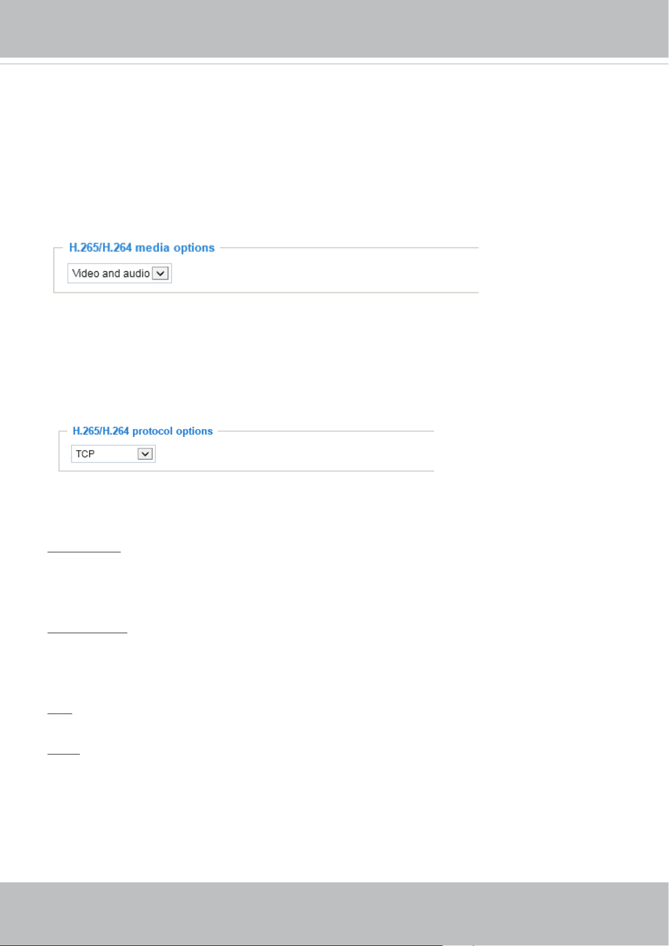
H.265 / H.264 Media Options
Select to stream video or audio data or both. This is enabled only when the video mode is set to H.264.
H.265 / H.264 Protocol Options
Depending on your network environment, there are four transmission modes of H.264 streaming:
UDP unicast: This protocol allows for more real-time audio and video streams. However, network
packets may be lost due to network burst trac and images may be broken. Activate UDP connection
when occasions require time-sensitive responses and the video quality is less important. Note that each
unicast client connecting to the server takes up additional bandwidth and the Network Camera allows up
to ten simultaneous accesses.
UDP multicast: This protocol allows multicast-enabled routers to forward network packets to all clients
requesting streaming media. This helps to reduce the network transmission load of the Network Camera
while serving multiple clients at the same time. Note that to utilize this feature, the Network Camera must
be configured to enable multicast streaming at the same time. For more information, please refer to
RTSP Streaming on page 105.
TCP: This protocol guarantees the complete delivery of streaming data and thus provides better video
quality. The downside of this protocol is that its real-time eect is not as good as that of the UDP protocol.
HTTP: This protocol allows the same quality as TCP protocol without needing to open specic ports for
streaming under some network environments. Users inside a firewall can utilize this protocol to allow
streaming data through.
H.264 Protocol Options
VIVOTEK
User's Manual - 51
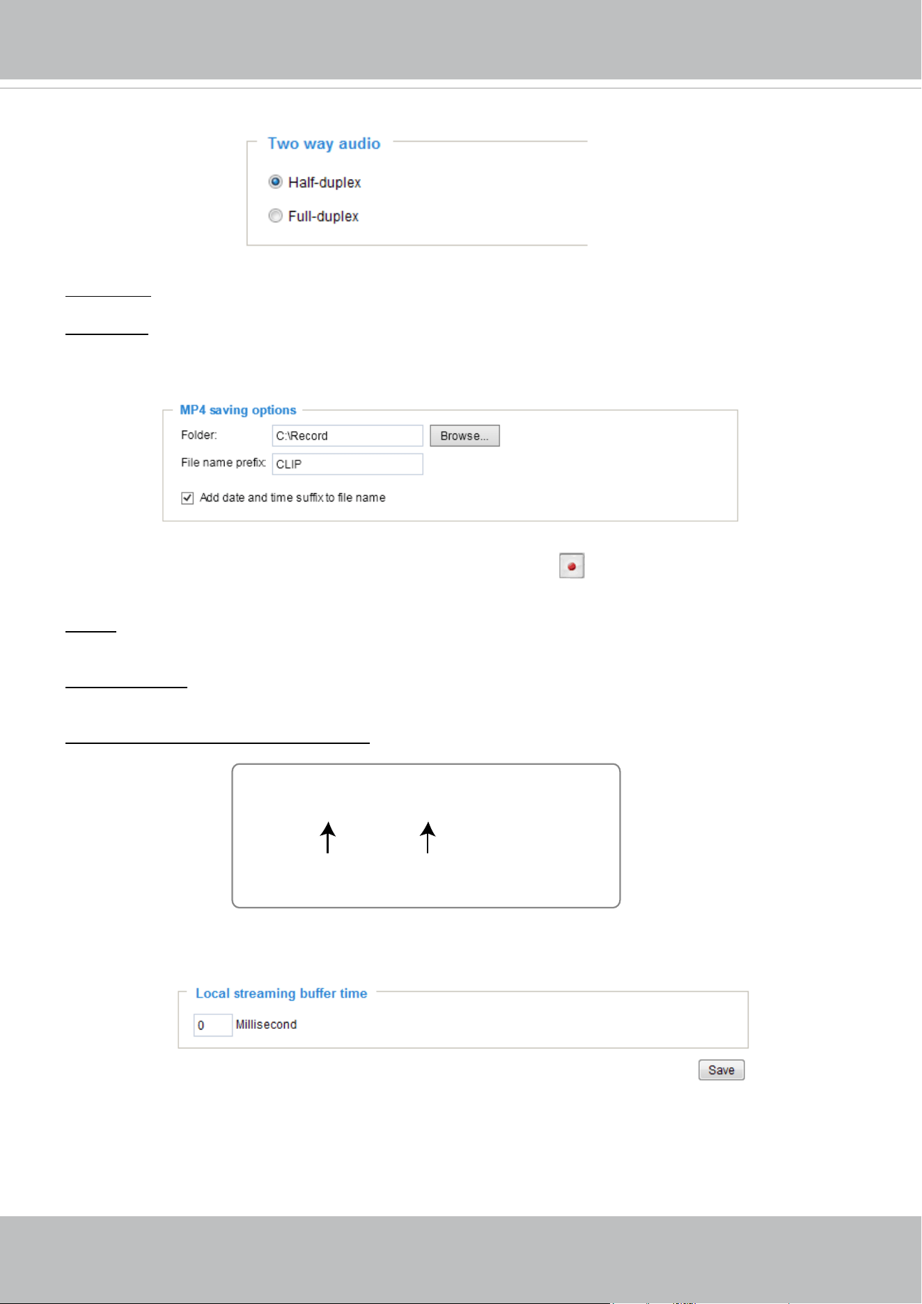
MP4 Saving Options
Users can record live video as they are watching it by clicking Start MP4 Recording on the main
page. Here, you can specify the storage destination and le name.
Folder: Specify a storage destination on your PC for the recorded video files. The location can be
changed.
File name prex: Enter the text that will be appended to the front of the video le name. A specied folder
will be automatically created on your local hard disk.
Add date and time sux to the le name: Select this option to append the date and time to the end of the
le name.
Local Streaming Buer Time
In the case of encountering unsteady bandwidth, live streaming may lag and video streaming may not be
very smoothly. If you enable this option, the live streaming will be stored temporarily on your PC’s cache
memory for a few milli seconds before being played on the live viewing window. This will help you see
the streaming more smoothly. If you enter 3,000 Millisecond, the streaming will delay for 3 seconds.
CLIP_20190321-180853
Date and time suffix
The format is: YYYYMMDD_HHMMSS
File name prefix
Two way audio
Half duplex: Audio is transmitted from one direction at a time, e.g., from a PC holding a web console with
the camera.
Full duplex: Audio is transmitted in both directions simultaneously.
VIVOTEK
52 - User's Manual
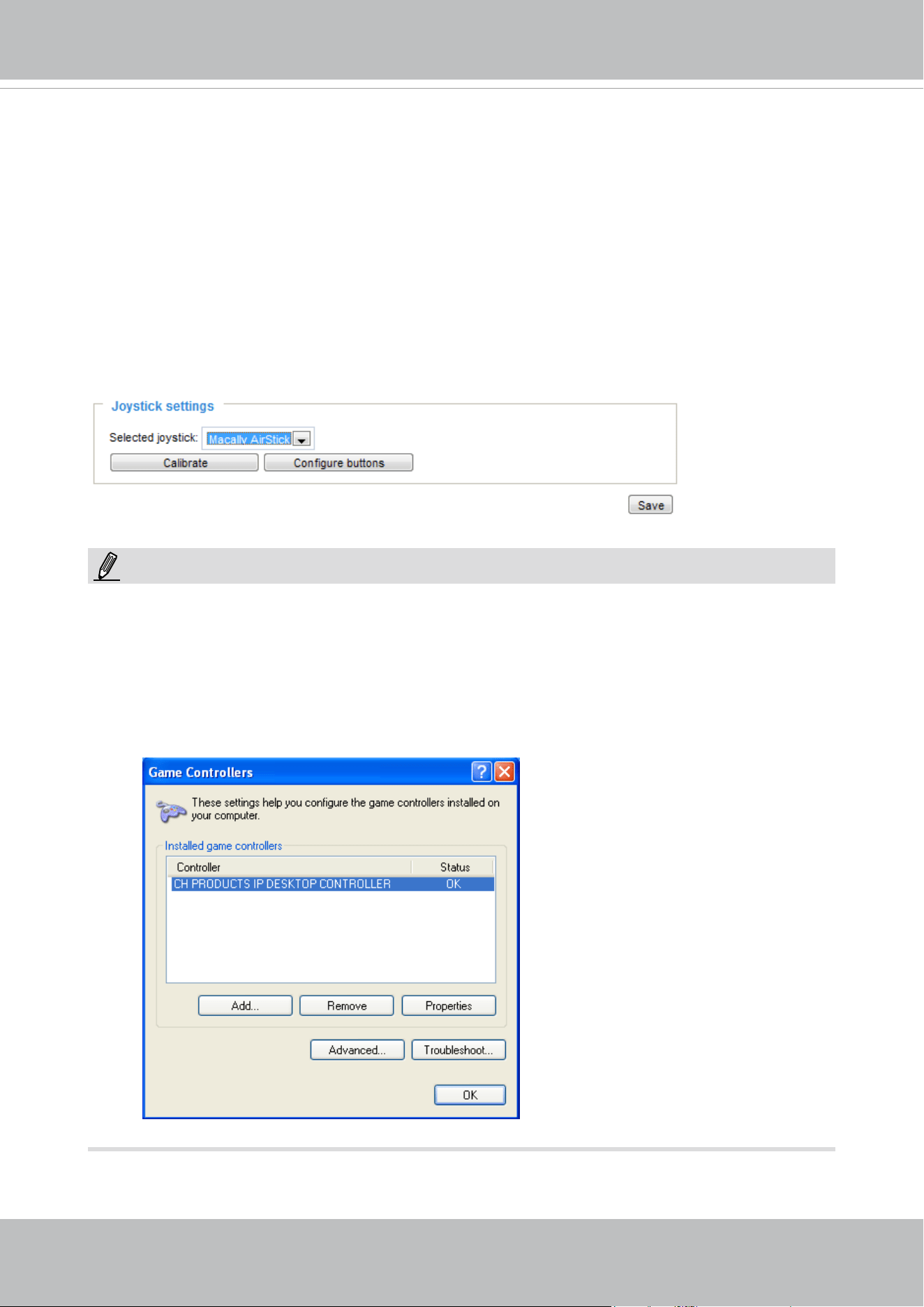
Joystick settings
Enable Joystick
Connect a joystick to a USB port on your management computer. Supported by the plug-in
(Microsoft’s DirectX), once the plug-in for the web console is loaded, it will automatically detect if
there is any joystick on the computer. The joystick should work properly without installing any other
driver or software.
Then you can begin to configure the joystick settings of connected devices. Please follow the
instructions below to enable joystick settings.
1. Select a detected joystick, if there are multiple, from the Selected joystick menu. If your joystick
is not detected, if may be defective.
2. Click Calibrate or Congure buttons to congure the joystick-related settings.
• If you want to assign Preset actions to your joystick, the preset locations should be congured
in advance in the Conguration > PTZ page. In Windows, use the search function on the Start
menu to search for Game Controller.
• If your joystick is not working properly, it may need to be calibrated. Click the Calibrate button
to open the Game Controllers window located in Microsoft Windows control panel and follow the
instructions for trouble shooting.
NOTE:
• The joystick will appear in the Game Controllers list in the Windows Control panel. If you want to
check out for your devices, go to the following page: Start -> Control Panel -> Game Controllers.
VIVOTEK
User's Manual - 53
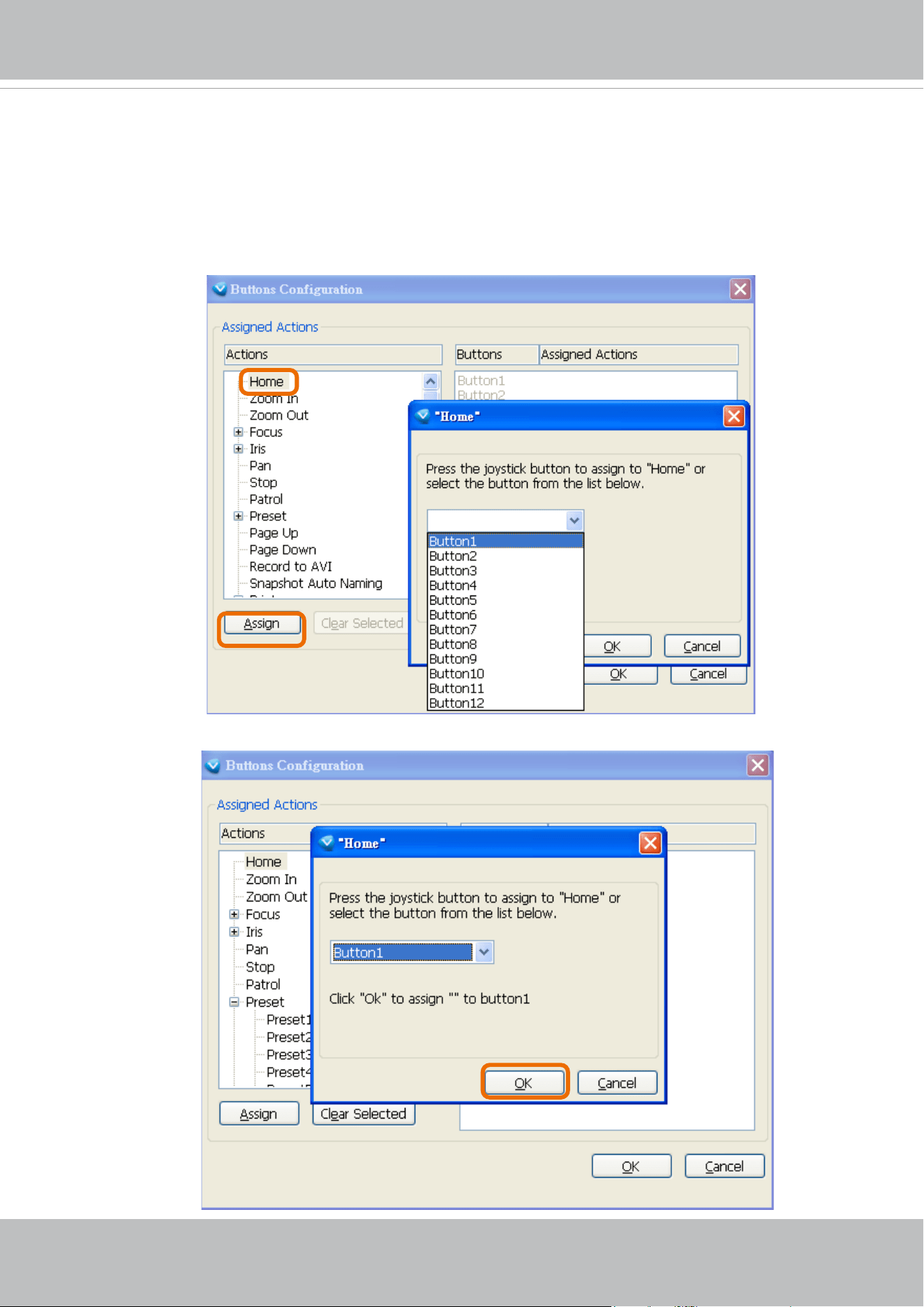
Buttons Conguration
In the Button Conguration window, the left column shows the actions you can assign, and the right
column shows the functional buttons and assigned actions. The number of buttons may dier from
dierent joysticks.
Please follow the steps below to congure your joystick buttons:
1. Choosing one of the actions and click Assign will pop up a dialog. Then you can assign this
action to a button by pressing the joystick button or select it from the drop-down list.
For example: Assign Home (move to home position) to Button 1.
2. Click OK to conrm the conguration.
VIVOTEK
54 - User's Manual
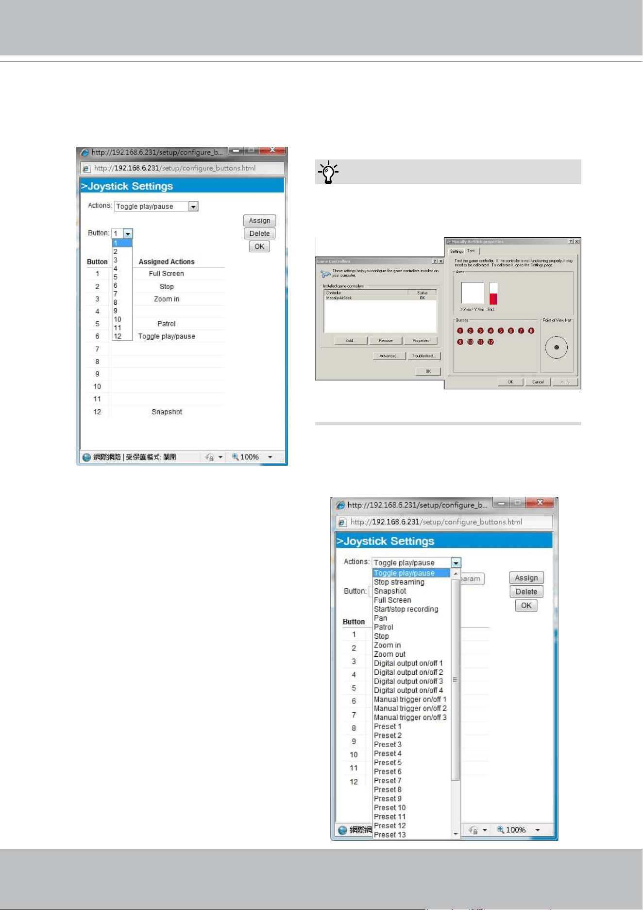
Buttons Conguration
Click the Congure Buttons button, a window will prompt as shown below. Please follow the steps
below to congure your joystick buttons:
1. Select a button number from the Button # pull-down menu.
2. Select a corresponding action, such as Patrol or Preset#.
If you are not sure of the locations of each
button, use the Properties window in the Game
Controllers utility.
Tips:
3.
Click the Assign button to assign an action to
the button. You can delete an association by
selecting a button number, and then click the
Delete button.
Repeat the process until you are done with the
conguration of all preferred actions.
The buttons you define should appear on the
button list accordingly.
4. Please remember to c
lick the Save button
on the Client settings page to preserver your
settings.
VIVOTEK
User's Manual - 55
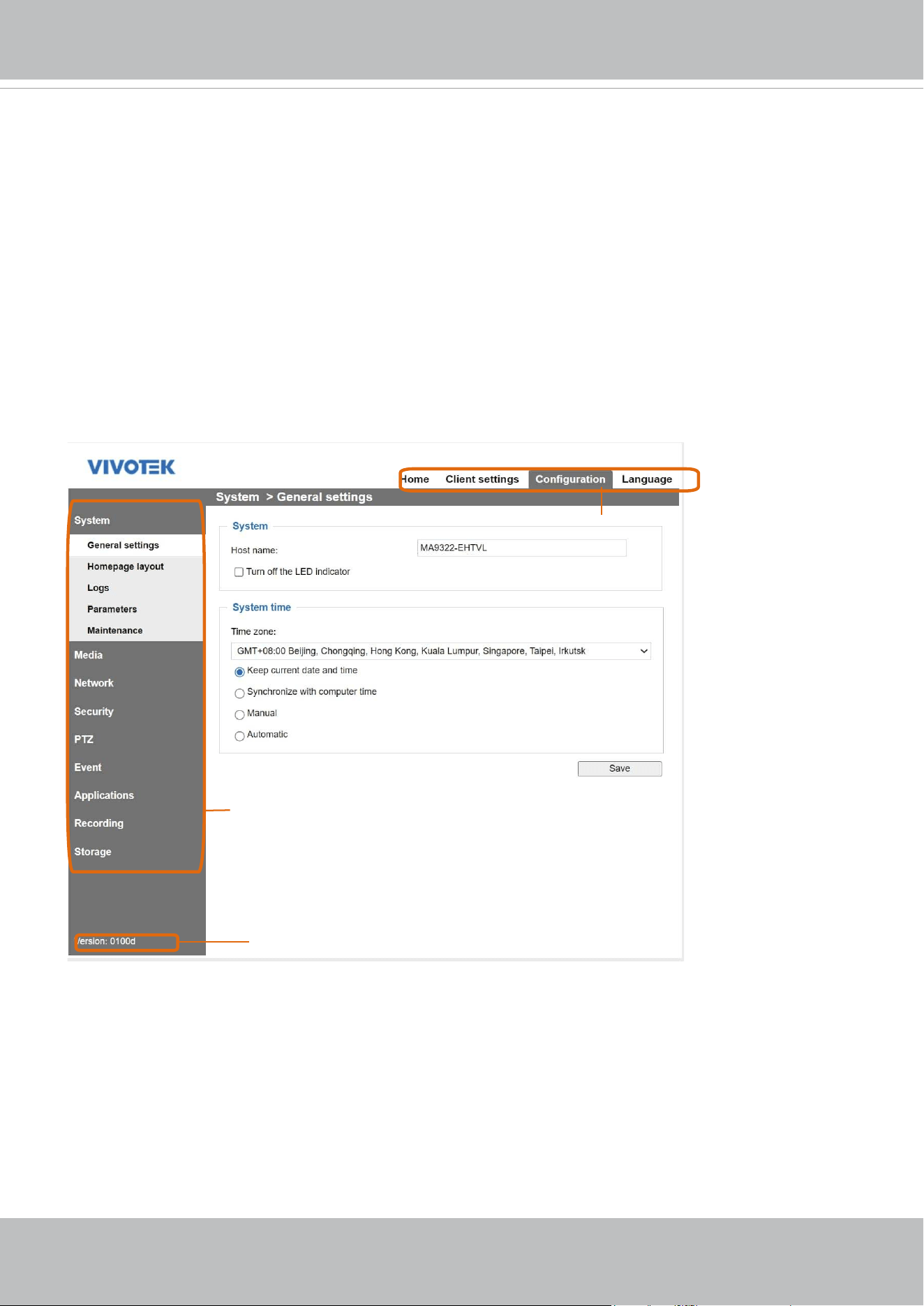
Conguration
Click Configuration on the main page to enter the camera setting pages. Note that only
Administrators can access the conguration page.
VIVOTEK provides an easy-to-use user interface that helps you set up your network camera
with minimal effort. In order to simplify the user interface, detailed information will be hidden
unless you click on the function item. When you click on the first sub-item, the detailed
information for the rst sub-item will be displayed; when you click on the second sub-item, the
detailed information for the second sub-item will be displayed and that of the rst sub-item will
be hidden.
The following is the interface of the main page:
Each function on the conguration list will be explained in the following sections.
The Navigation Area provides access to all different views from the Home page (for live viewing),
Conguration page, and multi-language selection.
Configuration List
Firmware Version
Navigation Area
VIVOTEK
56 - User's Manual
System > General settings
This section explains how to congure the basic settings for the Network Camera, such as the
host name and system time. It is composed of the following two columns: System, and System
Time. When finished with the settings on this page, click Save at the bottom of the page to
enable the settings.
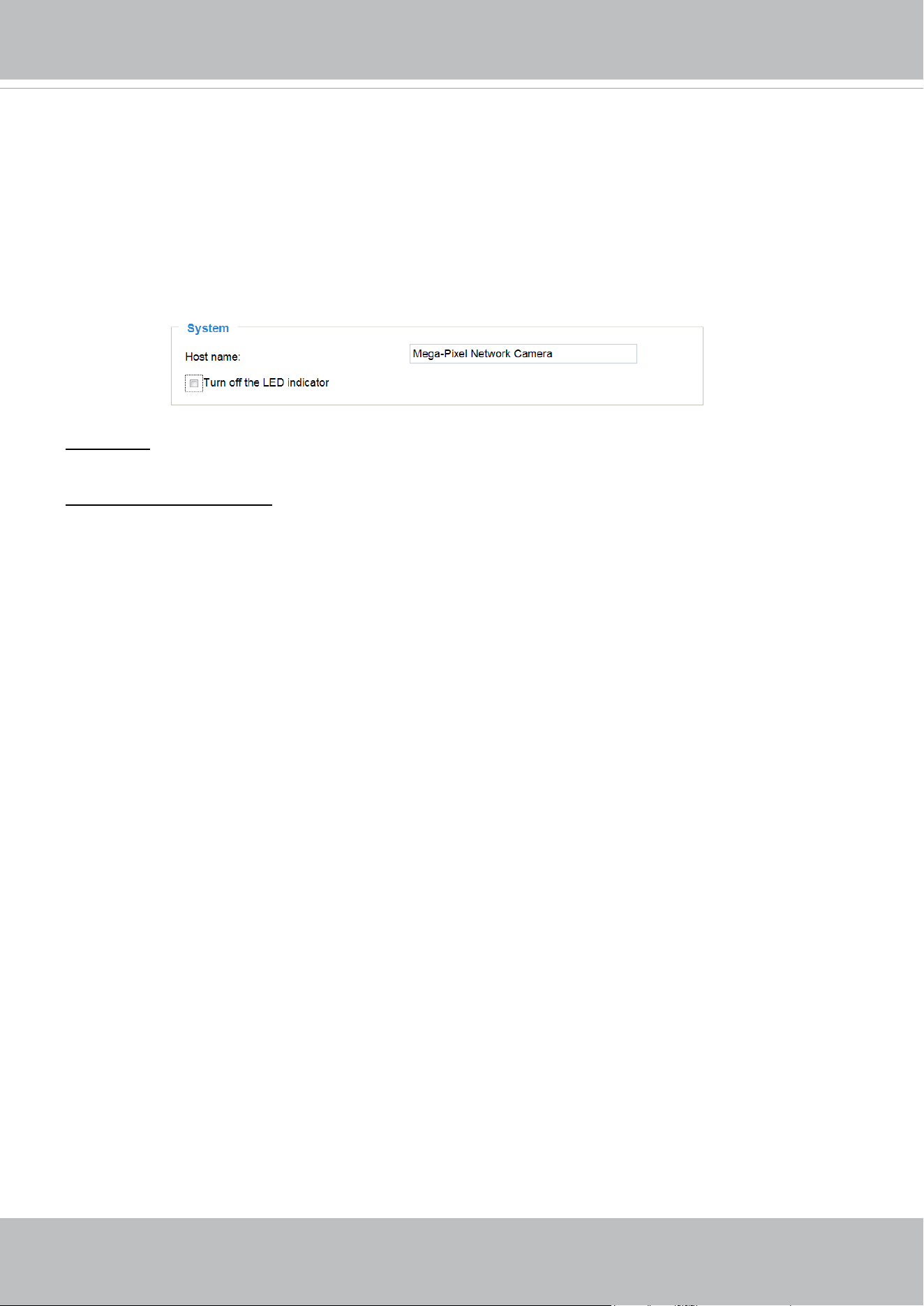
System
Host name: Enter a desired name for the Network Camera. The text will be displayed at the top of the
main page, and also on the view cells of the ST7501 and VAST management software.
Turn o the LED indicators: If you do not want others to notice the network camera is in operation, you
can select this option to turn o the LED indicators.
VIVOTEK
User's Manual - 57
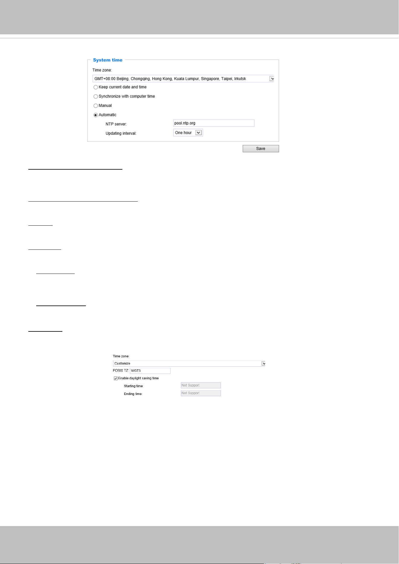
System time
Keep current date and time: Select this option to preserve the current date and time of the Network
Camera. The Network Camera’s internal real-time clock maintains the date and time even when the
power of the system is turned o.
Synchronize with computer time: Select this option to synchronize the date and time of the Network
Camera with the local computer. The read-only date and time of the PC is displayed as updated.
Manual: The administrator can enter the date and time manually. Note that the date and time format are
[yyyy/mm/dd] and [hh:mm:ss].
Automatic: The Network Time Protocol is a protocol which synchronizes computer clocks by periodically
querying an NTP Server.
NTP server: Assign the IP address or domain name of the time-server. Leaving the text box blank
connects the Network Camera to the default time servers. The precondition is that the camera must
have the access to the Internet.
Update interval: Select to update the time using the NTP server on an hourly, daily, weekly, or monthly
basis.
Time zone : Select the appropriate time zone from the list. You can scroll down on the Time zone menu to
nd the Customize option and use the POSIX TZ variables. For example,
http://www.gnu.org/software/
libc/manual/html_node/TZ-Variable.html.
Here are some examples for TZ values, including the appropriate Daylight Saving Time and its
dates of applicability. In North American Eastern Standard Time (EST) and Eastern Daylight
Time (EDT), the normal offset from UTC is 5 hours; since this is west of the prime meridian,
the sign is positive. Summer time begins on March’s second Sunday at 2:00am, and ends on
November’s rst Sunday at 2:00am. EST+5EDT,M3.2.0/2,M11.1.0/2
Israel Standard Time (IST) and Israel Daylight Time (IDT) are 2 hours ahead of the prime
meridian in winter, springing forward an hour on March’s fourth Thursday (i.e., on the rst Friday
on or after March 23), and falling back on October’s last Sunday.
IST-2IDT,M3.4.4,M10.5.0

VIVOTEK
58 - User's Manual
Western Argentina Summer Time (WARST) is 3 hours behind the prime meridian all year.
There is a dummy fall-back transition on December 31 at 25:00 daylight saving time (i.e.,
24:00 standard time, equivalent to January 1 at 00:00 standard time), and a simultaneous
spring-forward transition on January 1 at 00:00 standard time, so daylight saving time is in
eect all year and the initial WART is a placeholder.
The format is TZ = local_timezone,date/time,date/time.
Here, date is in the Mm.n.d format, where:
Mm (1-12) for 12 months
n (1-5) 1 for the rst week and 5 for the last week in the month
d (0-6) 0 for Sunday and 6 for Saturday
CST6CDT is the name of the time zone
CST is the abbreviation used when DST is o
6 hours is the time dierence from GMT
CDT is the abbreviation used when DST is on
,M3 is the third month
.2 is the second occurrence of the day in the month
.0 is Sunday
/2 is the time
,M11 is the eleventh month
.1 is the rst occurrence of the day in the month
.0 is Sunday
/2 is the time
The minimum specier is down to the hour.
VIVOTEK
User's Manual - 59
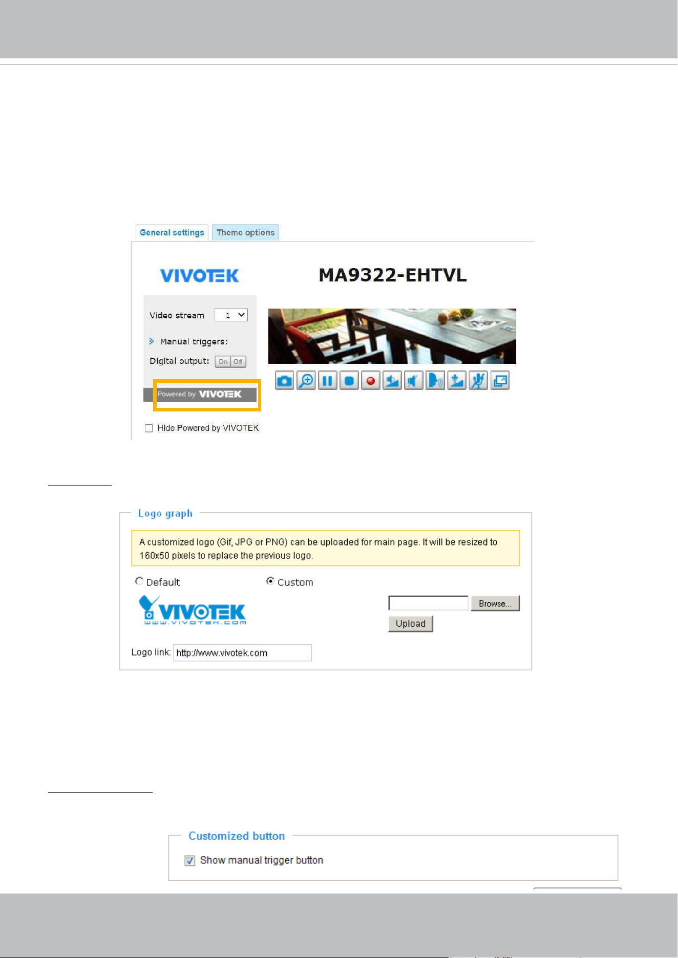
System > Homepage layout
This section explains how to set up your own customized homepage layout.
General settings
This column shows the settings of your hompage layout. You can manually select the background and
font colors in Theme Options (the second tab on this page). The settings will be displayed automatically
in this Preview eld. The following shows the homepage using the default settings:
Follow the steps below to upload a new logo:
1. Click Custom and the Browse eld will appear.
2. Select a logo from your les.
3. Click Upload to replace the existing logo with a new one.
4. Enter a website link if necessary.
5. Click Save to enable the settings.
Customized button
If you want to hide manual trigger buttons on the homepage, please uncheck this item. This item is
checked by default.
Logo graph
Here you can change the logo that is placed at the top of your homepage.
■ Hide Powered by VIVOTEK: If you check this item, it will be removed from the homepage.
VIVOTEK
60 - User's Manual
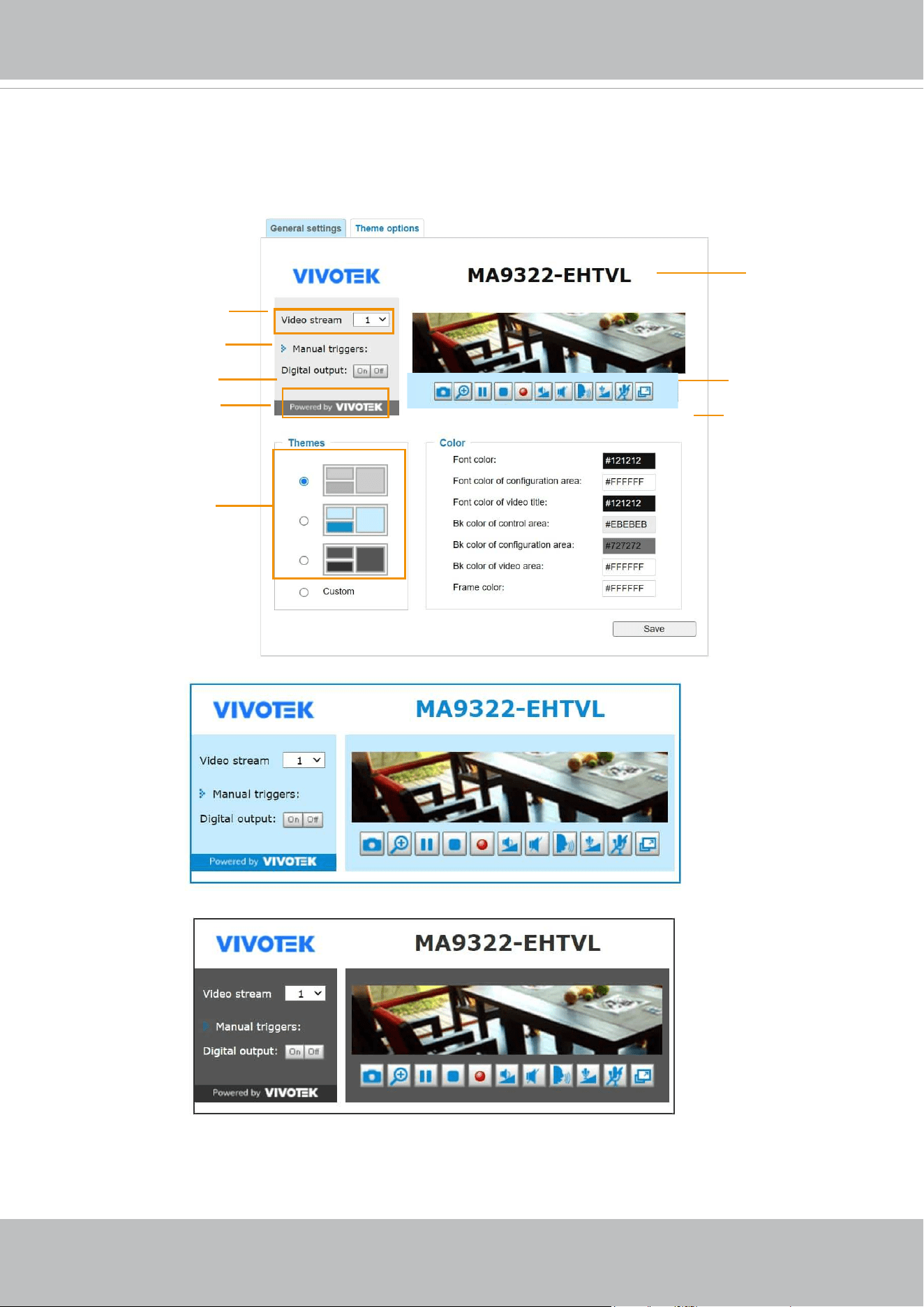
Theme Options
Here you can change the color of your homepage layout. There are three types of preset patterns for you
to choose from. The new layout will simultaneously appear in the Preview led. Click Save to enable the
settings.
Font Color of the
Video Title
Background Color of
the Video Area
Frame Color
Font Color
Background Color of the
Control Area
Font Color of
the Configuration Area
Background Color of the
Configuration Area
Preset patterns
VIVOTEK
User's Manual - 61
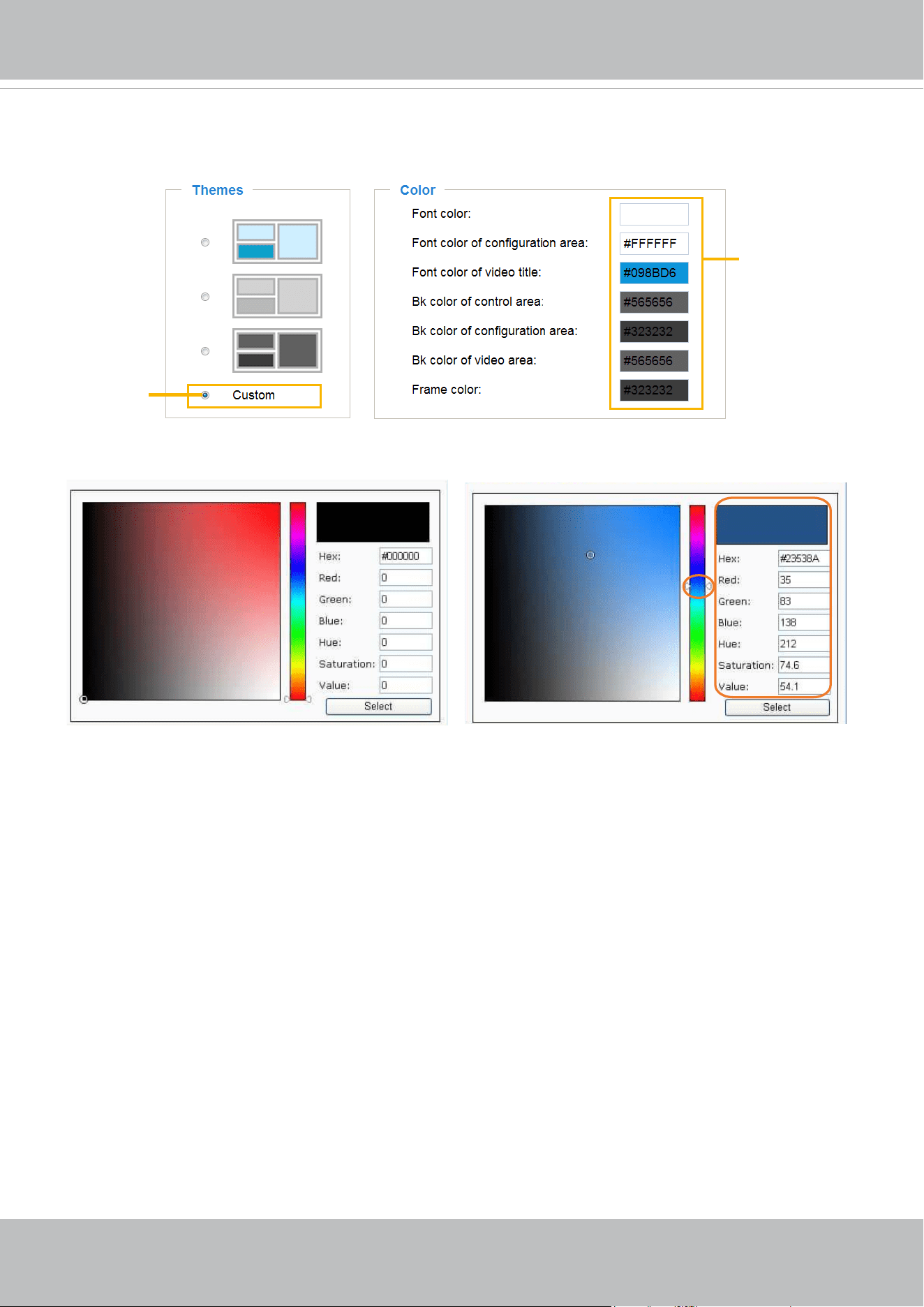
■ Follow the steps below to set up the customed homepage:
1. Click Custom on the left column.
2. Click the eld where you want to change the color on the right column.
3. The palette window will pop up as shown below.
4. Drag the slider bar and click on the left square to select a desired color.
5. The selected color will be displayed in the corresponding elds and in the Preview column.
6. Click Save to enable the settings.
1
2
3
4
Color Selector
Custom
Pattern
VIVOTEK
62 - User's Manual
System > Logs
This section explains how to congure the Network Camera to send the system log to a remote
server as backup.
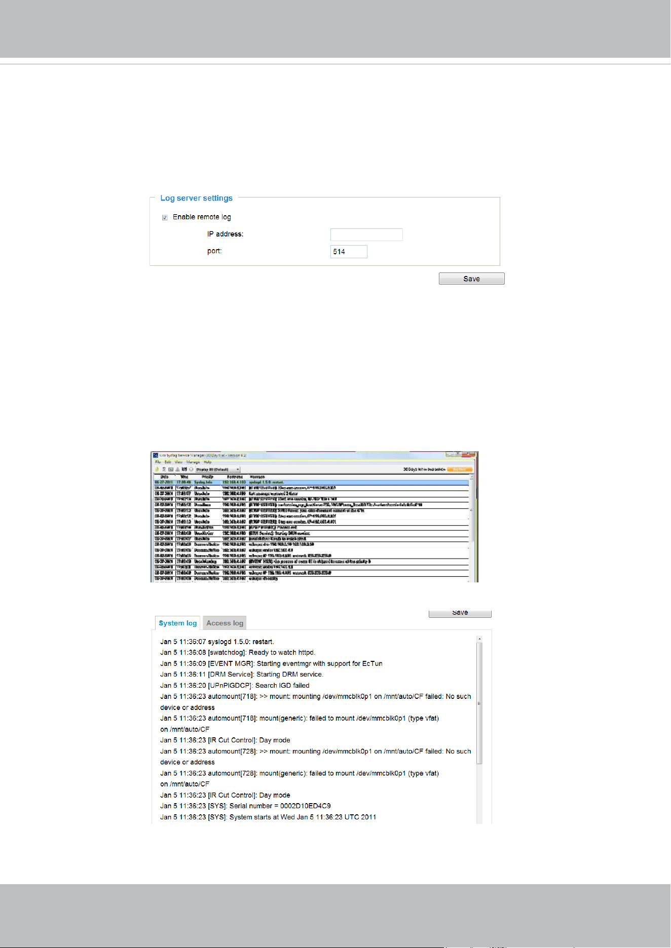
Log server settings
Follow the steps below to set up the remote log:
1. Select Enable remote log.
2. In the IP address text box, enter the IP address of the remote server.
2. In the port text box, enter the port number of the remote server.
3. When completed, click Save to enable the setting.
You can congure the Network Camera to send the system log le to a remote server as a log backup.
Before utilizing this feature, it is suggested that the user install a log-recording tool to receive system log
messages from the Network Camera. An example is Kiwi Syslog Daemon. Visit
http://www.kiwisyslog.
com/kiwi-syslog-daemon-overview/
.
This column displays the system log in a chronological order. The system log is stored in the Network
Camera’s buer area and will be overwritten when reaching a certain limit.
System log
VIVOTEK
User's Manual - 63
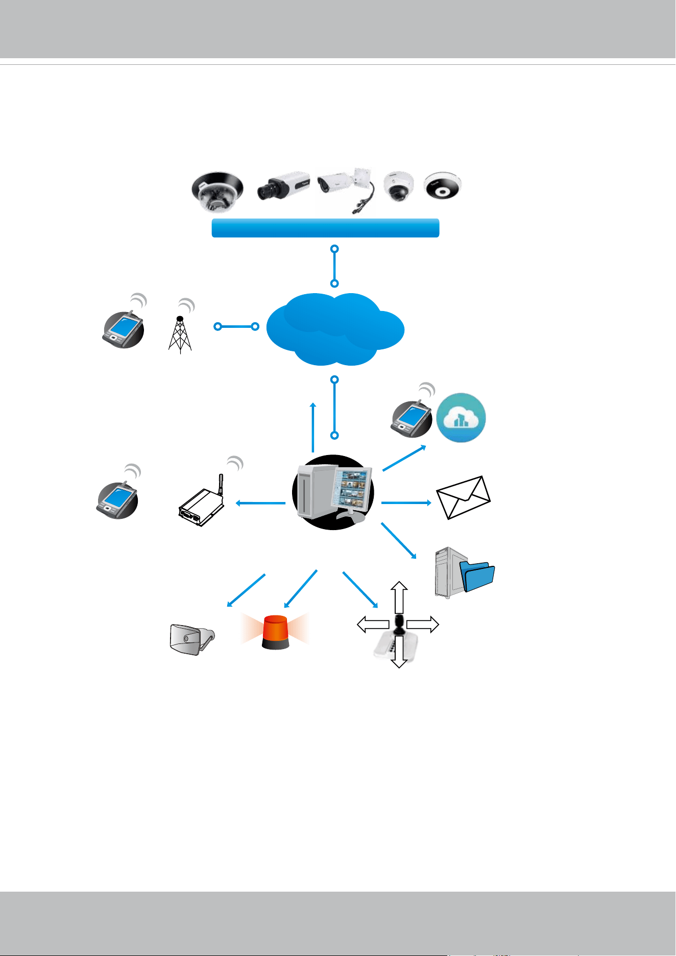
Server with
VAST Recording Software
Internet
VIVOTEK Network Cameras
3G Cell phone
Cell phone
Short message
Email
GSM
Modem
HTTP
Digital output
VIVOCloud
PTZ
Deterrent
FTP
You can install the included VAST recording software, which provides an Event
Management function group for delivering event messages via emails, GSM short
messages, onscreen event panel, or to trigger an alarm, etc. For more information, refer to
the VAST User Manual.
VIVOTEK
64 - User's Manual
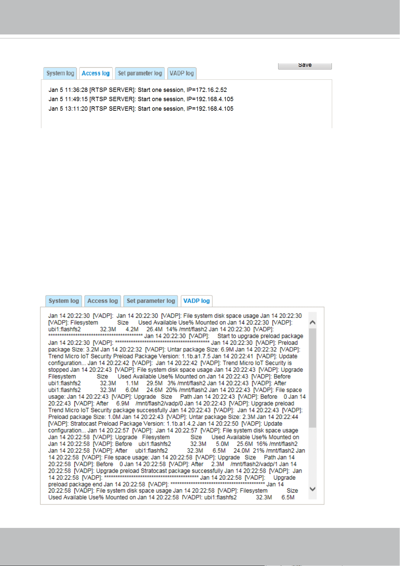
Access log
Access log displays the access time and IP address of all viewers (including operators and
administrators) in a chronological order. The access log is stored in the Network Camera’s buer
area and will be overwritten when reaching a certain limit.
VADP log
VADP log contains the information for the onboard VADP packages, including memory usage,
module load and unload information.
Set Parameter log
VADP log contains the history of changes made to system parameters such as recording, imaging
parameters, and all other parameters.
VIVOTEK
User's Manual - 65
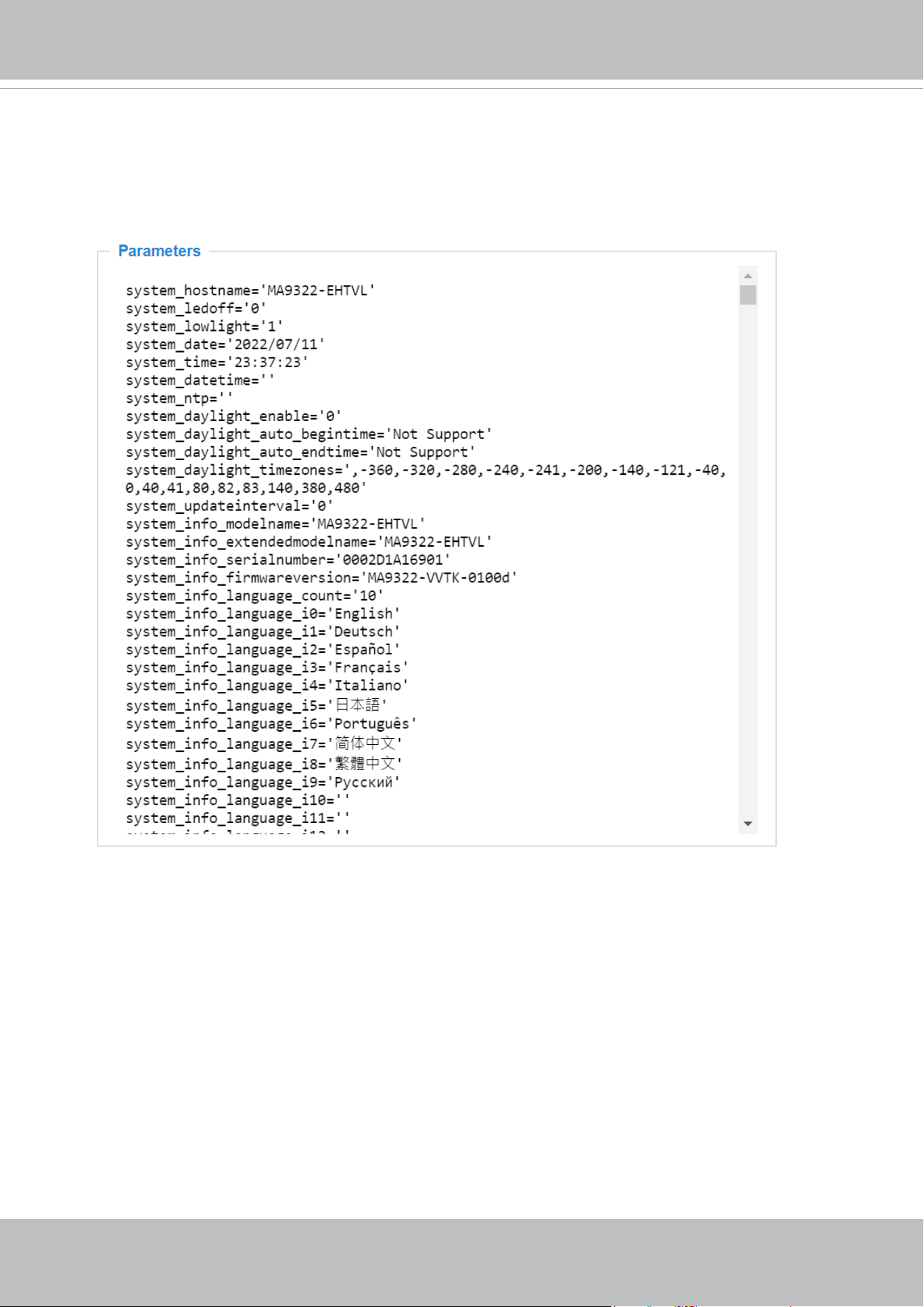
System > Parameters
The View Parameters page lists the entire system’s parameters. If you need technical
assistance, please provide the information listed on this page.
VIVOTEK
66 - User's Manual
System > Maintenance
This chapter explains how to restore the Network Camera to factory default, upgrade rmware
version, etc.
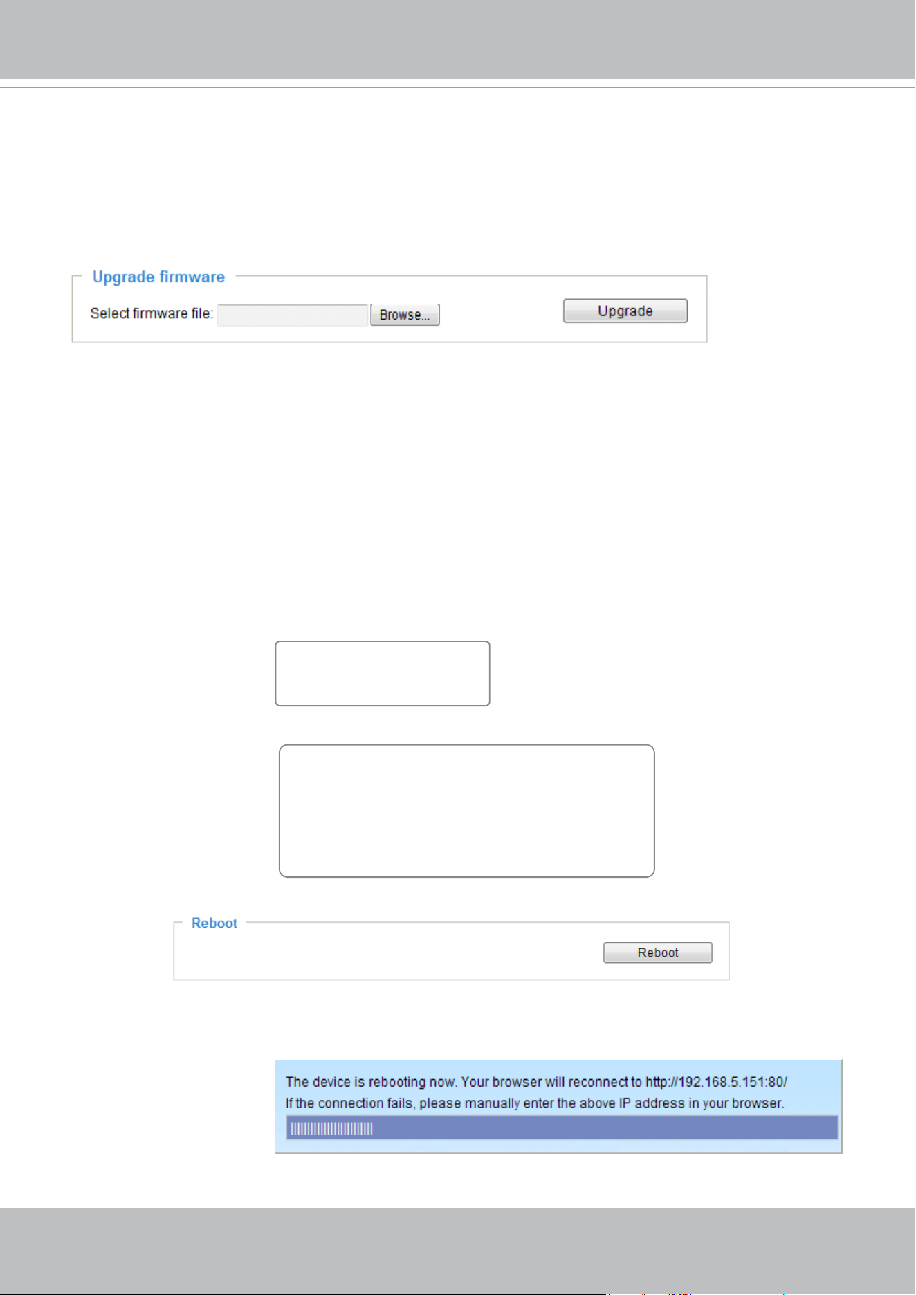
General settings > Upgrade rmware
This feature allows you to upgrade the firmware of your Network Camera. It takes a few minutes to
complete the process.
Note: Do not power o the Network Camera during the upgrade!
Follow the steps below to upgrade the rmware:
1. Download the latest rmware le from the VIVOTEK website. The le is in .pkg le format.
2. Click Browse… and locate the rmware le.
3. Click Upgrade. The Network Camera starts to upgrade and will reboot automatically when the upgrade
completes.
If the upgrade is successful, you will see “Reboot system now!! This connection will close”. After that, re-
access the Network Camera.
The following message is displayed when the upgrade has succeeded.
The following message is displayed when you have selected an incorrect rmware le.
General settings > Reboot
This feature allows you to reboot the Network Camera, which takes about one minute to complete. When
completed, the live video page will be displayed in your browser. The following message will be displayed
during the reboot process.
If the connection fails after rebooting, manually enter the IP address of the Network Camera in the
address eld to resume the connection.
Starting firmware upgrade...
Do not power down the server during the upgrade.
The server will restart automatically after the upgrade is
completed.
This will take about 1 - 5 minutes.
Wrong PKG file format
Unpack fail
Reboot system now!!
This connection will close.
VIVOTEK
User's Manual - 67
IMPORTANT:
Through extensive use, temporary les may accumulate that disable a rmware upgrade. You can
use the Clean up function in the Application > Package management window to solve this problem.
VIVOTEK
68 - User's Manual
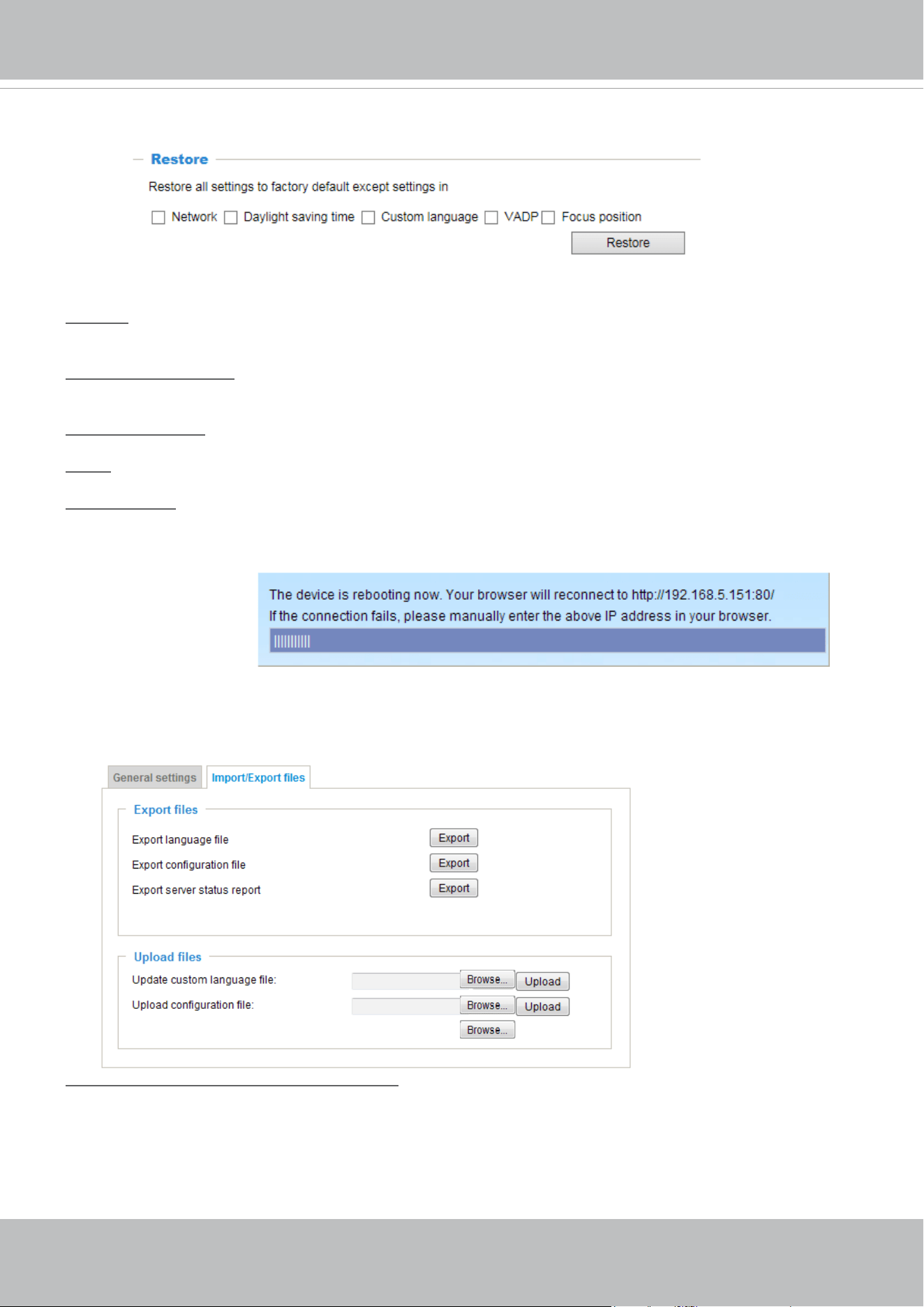
General settings > Restore
This feature allows you to restore the Network Camera to factory default settings.
Network: Select this option to retain the Network Type settings (please refer to Network Type on page
98).
Daylight Saving Time: Select this option to retain the Daylight Saving Time settings (please refer to
Import/Export les below on this page).
Custom Language: Select this option to retain the Custom Language settings.
VADP: Retain the VADP modules (3rd-party software stored on the SD card) and related settings.
Focus position: Retain the lens focus position using the previously saved position parameters.
If none of the options is selected, all settings will be restored to factory default. The following message is
displayed during the restoring process.
Import/Export les
This feature allows you to Export / Update daylight saving time rules, custom language le, conguration
le, and server status report.
Export daylight saving time conguration le: Click to set the start and end time of DST (Daylight Saving).
Follow the steps below to export:
1. In the Export les column, click Export to export the daylight saving time conguration le from the
Network Camera.
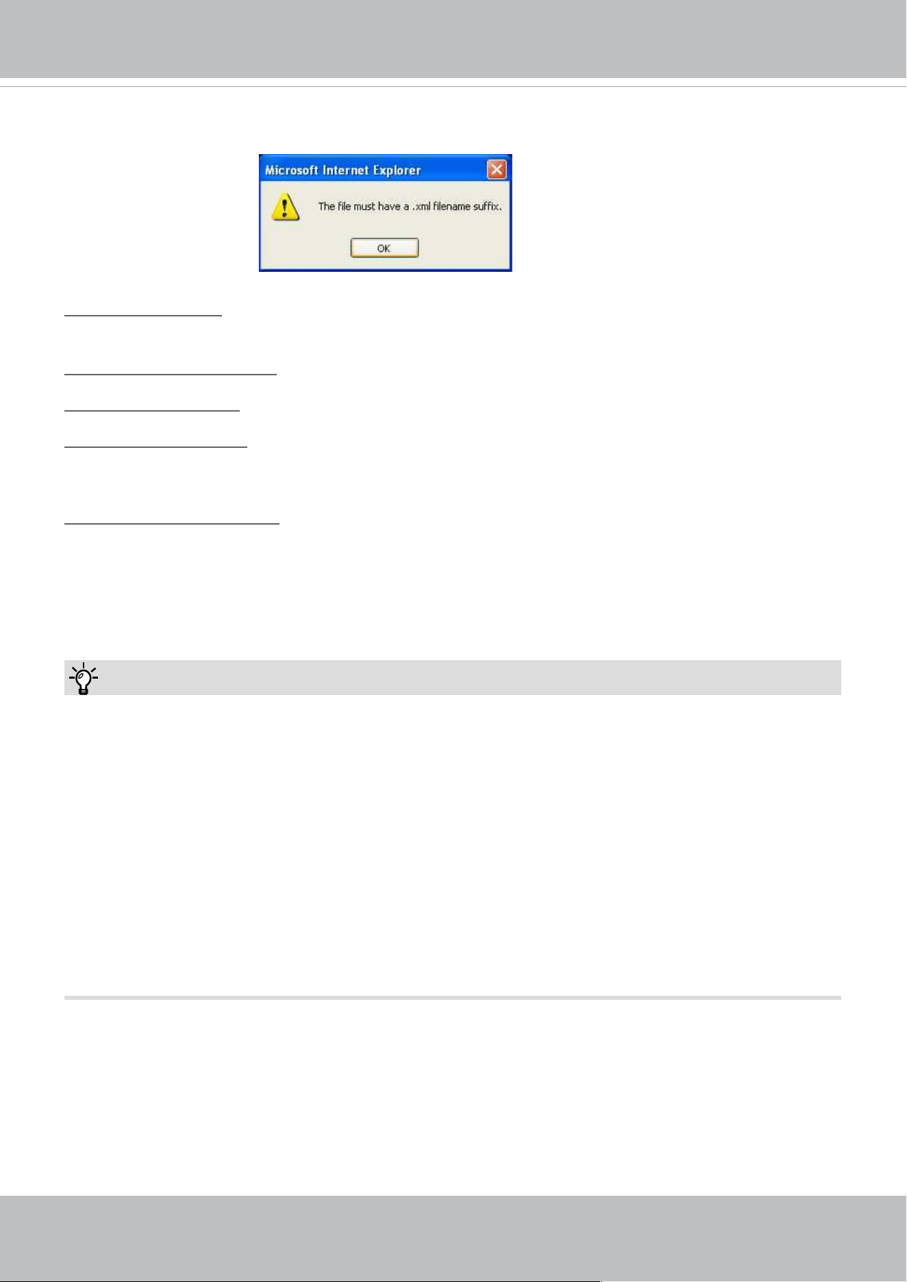
2. A le download dialog will pop up as shown below. Click Open to review the XML le or click Save to
store the le for editing.
VIVOTEK
User's Manual - 69
The following message is displayed when attempting to upload an incorrect le format.
Export language file: Click to export language strings. VIVOTEK provides nine languages: English,
Deutsch, Español, Français, Italiano,
日本語,
Português,
簡体中文
,
繁體中文,
and
Ρусский
.
.
Update custom language le: Click Browse… and specify your own custom language le to upload.
Export conguration le: Click to export all parameters for the device and user-dened scripts.
Update conguration le: Click Browse… to update a conguration le. Please note that the model and
rmware version of the device should be the same as the conguration le. If you have set up a xed IP
or other special settings for your device, it is not suggested to update a conguration le.
Export server staus report: Click to export the current server status report, such as time, logs,
parameters, process status, memory status, le system status, network status, kernel message ... and so
on.
Tips:
If a rmware upgrade is accidentally disrupted, say, by a power outage, you still have a last resort method to
restore normal operation. See the following for how to bring the camera back to work:
Applicable scenario:
(a) Power disconnected during rmware upgrade.
(b) Unknown reason causing abnormal LED status, and a Restore cannot recover normal working
condition.
You can use the following methods to activate the camera with its backup rmware:
(a) Press and hold down the reset button for at least one minute.
(b) Power on the camera until the Red LED blinks rapidly.
(c) After boot up, the rmware should return to the previous version before the camera hanged. (The
procedure should take 5 to 10 minutes, longer than the normal boot-up process). When tthis
process is completed, the LED status should return to normal.
VIVOTEK
70 - User's Manual
Media > Image
Channel: Select a Channel (one of the 4 sensors) before making congurations. These 4 sensors
can be individually congured.
This section explains how to configure the image settings of the Network Camera. It is
composed of the following function groups: General settings, Image settings, Exposure,
Focus, and Privacy mask.
General settings
Video title
Show_timestamp_and video_title_in_video_and_snapshots: Enter a name that will be displayed on
the title bar of the live video as the picture shown below. A zoom indicator will be displayed on the
Home page when you zoom in/out on the live viewing window as shown below. You may zoom in/
out on the image by scrolling the mouse wheel inside the live viewing window, and the maximum
zoom in will be up to 4 times.
Position of timestamp and video title on image: Select to display time stamp and video title on the
top or at the bottom of the video stream.
Timestamp and video title font size: Select the font size for the time stamp and title.
Video font (.ttf): You can select a True Type font le for the display of textual messages on video.
Color: Select to display color or black/white video streams.
Power line frequency: Set the power line frequency consistent with local utility settings to eliminate
image flickering associated with fluorescent lights. Note that after the power line frequency is
changed, you must disconnect and reconnect the power cord of the Network Camera in order for
the new setting to take eect.
Video Title
Title and Time
Video 17:08:56 2014/7/09
2014/7/09 17:08:56
X2.1
Zoom Factor
Zoom In
Zoom Out
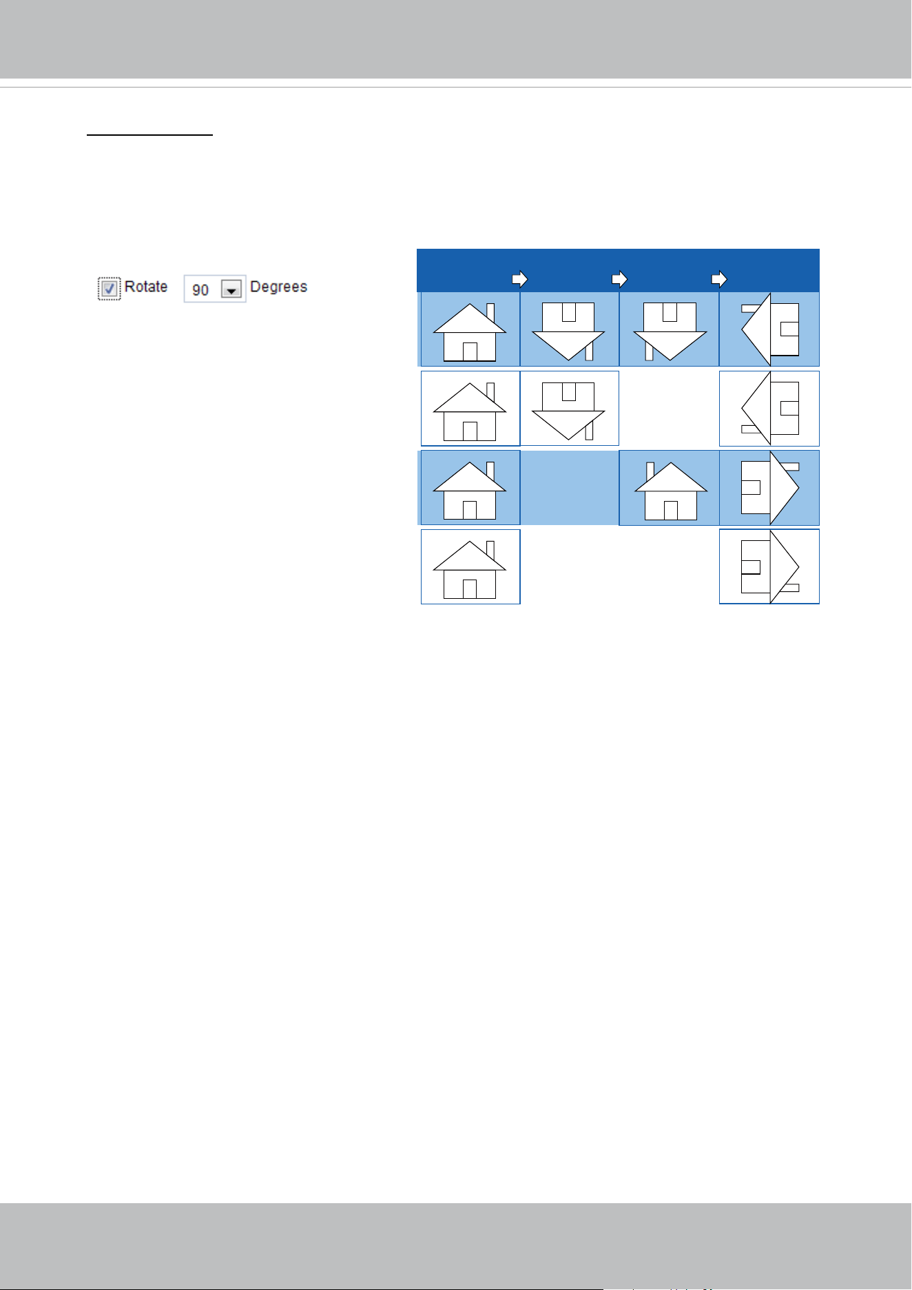
VIVOTEK
User's Manual - 71
Video orientation: Flip - vertically reect the display of the live video; Mirror - horizontally reect the
display of the live video. Select both options if the Network Camera is installed upside-down (e.g.,
on the ceiling) to correct the image orientation. Please note that if you have preset locations, those
locations will be cleared after ip/mirror setting.
Rotate -
MirrorNormal Flip Rotate 90°
clockwise
The camera may be installed on a vertical, side-facing, or tilted surface in order to accommodate
the interior or exterior design of a building. The interior of a building can be shaped as a narrow
rectangular space, such as a corridor. The conventional HD image, such as that of a 16:9 aspect
ratio, will be incongruous with its wide horizontal view. With video rotation, the camera can more
readily cover the eld of view on a tall and narrow scene.
The rotation here indicates clockwise
rotation. Rotation can be applied with
flip, mirror, and physical lens rotation
(see below) settings to adapt to different
mounting locations.
The gures in the illustration are shown in
a consecutive order.
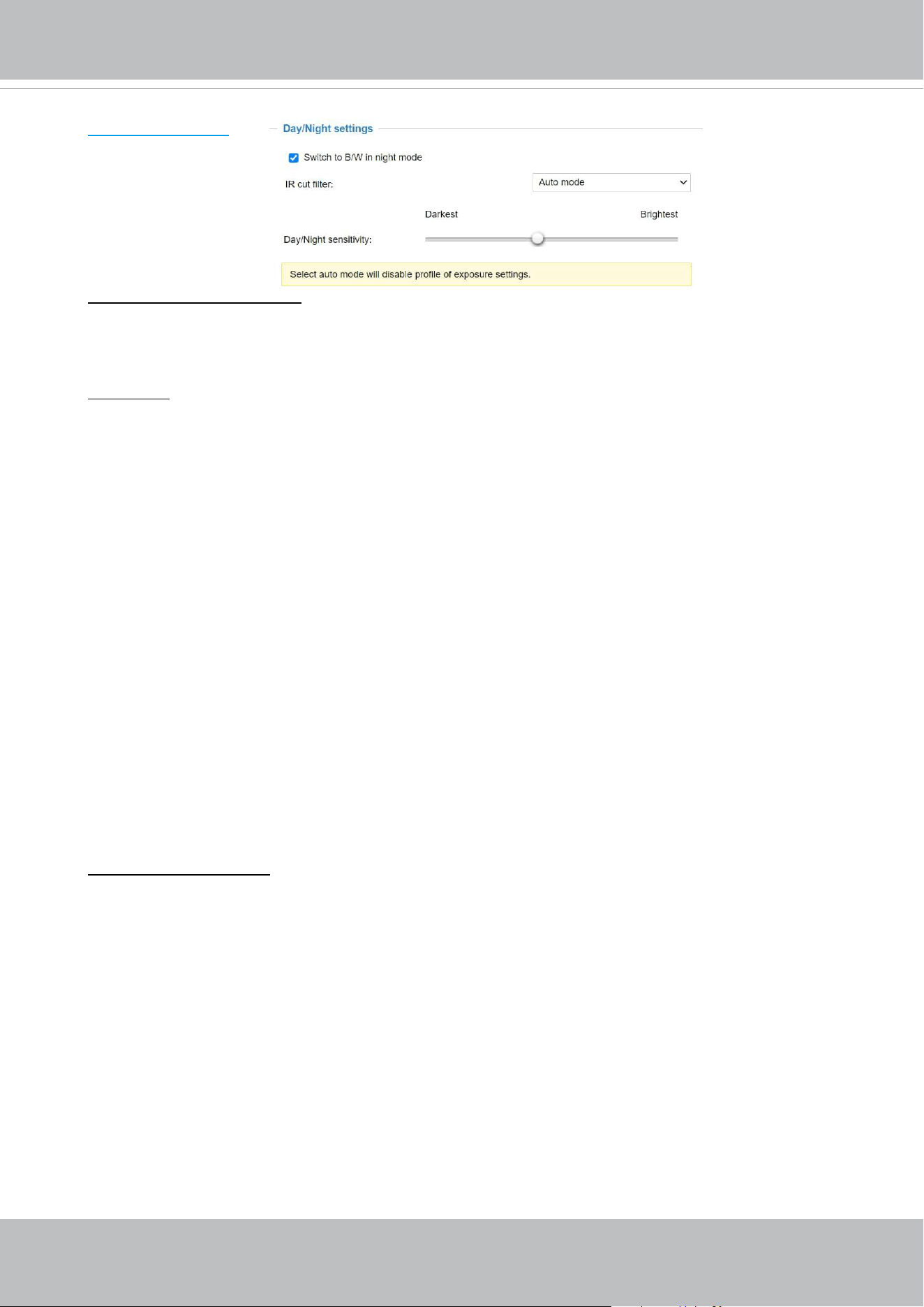
VIVOTEK
72 - User's Manual
Day/Night Settings
Switch to B/W in night mode
Select this to enable the Network Camera to automatically switch to Black/White during night
mode.
IR cut lter
With a removable IR-cut lter, this Network Camera can automatically remove the lter to let IR
light enter the light sensor during low light conditions.
■ Auto mode
The Network Camera automatically removes the lter by judging the level of ambient light.
■ Day mode
In day mode, the Network Camera switches on the IR cut lter at all times to block infrared light
from reaching the sensor so that the colors will not be distorted.
■ Night mode
In night mode, the Network Camera switches o the IR cut lter at all times for the sensor to
accept infrared light, thus helping to improve low light sensitivity.
■ Synchronize with digital input
The Network Camera automatically removes the IR cut lter when a Digital Input is triggerred.
For example, an external IR light may come with its own detection circuits.
■ Schedule mode
The Network Camera switches between day mode and night mode based on a specified
schedule. Enter the start and end time for the day mode. Note that the time format is [hh:mm]
and is expressed in 24-hour clock time. By default, the start and end time of day mode are set to
07:00 and 18:00.
Sensitivity of IR cut lter
Tune the responsiveness of the IR cut lter to lighting conditions as Low, Normal, or High.
When completed with the settings on this page, click Save to enable the settings.
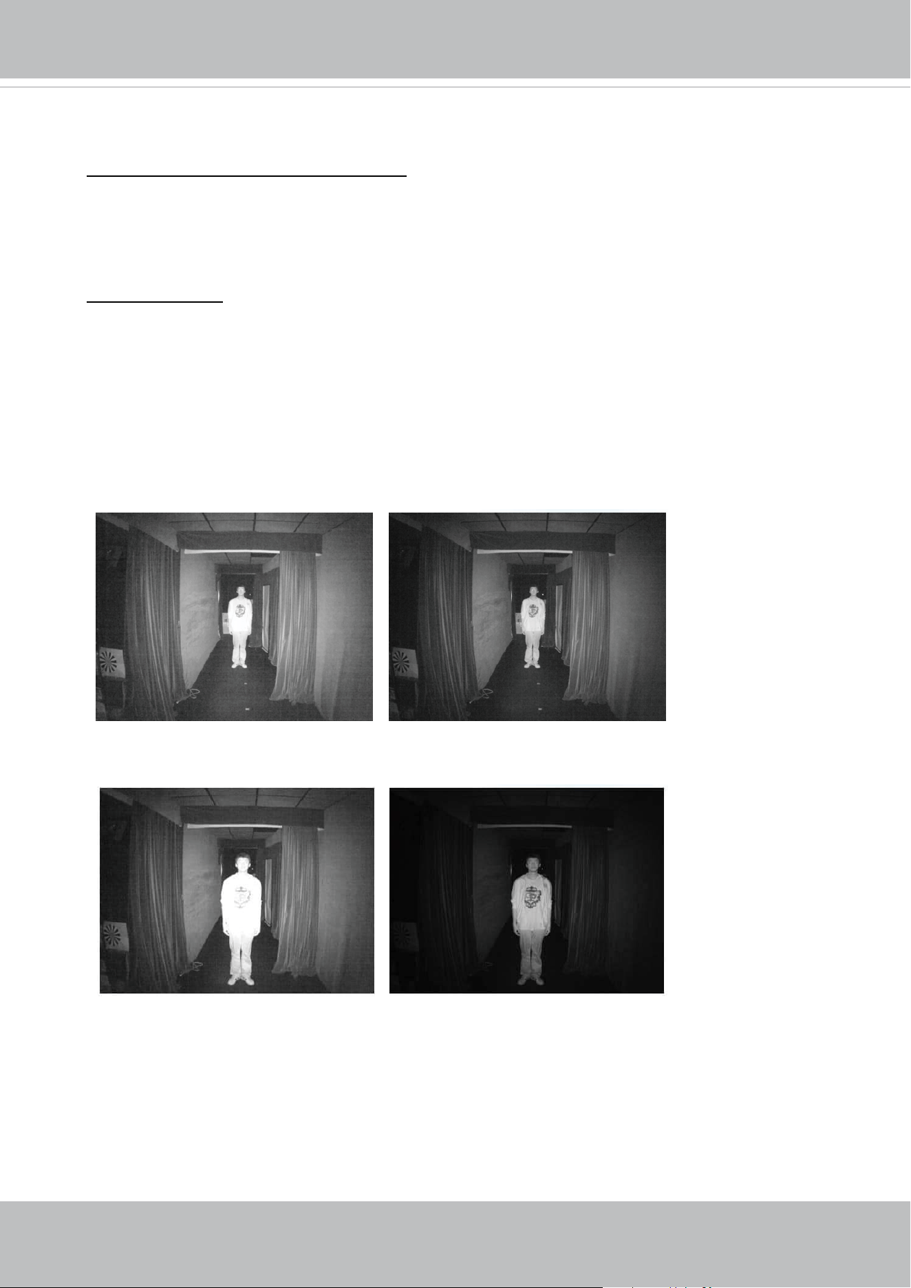
VIVOTEK
User's Manual - 73
Illuminators
Turn on built-in IR illuminator in night mode
Select this to turn on the camera’s onboard IR illuminator when the camera detects low light
condition and enters the night mode.
Smart IR disabled; distance: 5M
Smart IR enabled; distance: 5M
Smart IR disabled; distance: 3M
Smart IR enabled; distance: 3M
The Smart IR function is more benecial when the spot of intrusions or an object of your interest
is close to the lens and the IR lights. For example, if an intruder has a chance of getting near the
range of 3 meters, Smart IR can eectively reduce the over-exposure. For a surveillance area at a
greater distance, e.g., 5 meters or farther away, the Smart IR function may not bring as signicant
benets as in close range.
Anti-overexposure
When enabled, the camera automatically adjusts the IR projection to adjacent objects in order to
avoid over-exposure in the night mode.
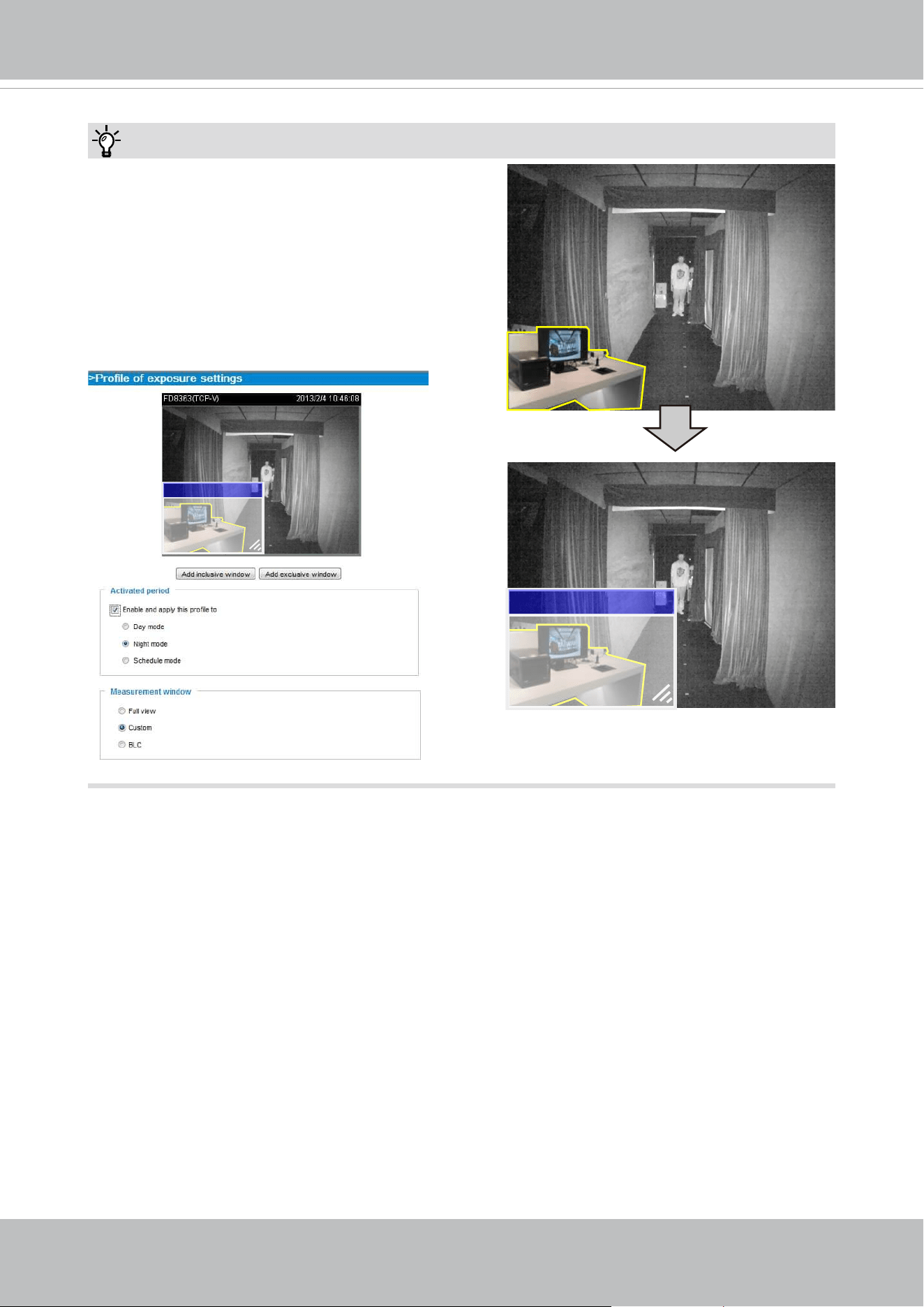
VIVOTEK
74 - User's Manual
Exclude x
Tips:
If there is an object in close proximity, the IR lights
reflected back from it can mislead the Smart IR’s
calculation of light level. To solve this problem, you
can place an “Exposure Exclude” window on an
unavoidable object in the Exposure setting window.
See page 77 for how to do it.
You can also configure the “Exposure Exclude”
window in a night mode “Prole” setting so that your
day time setting is not aected.
Exclude x
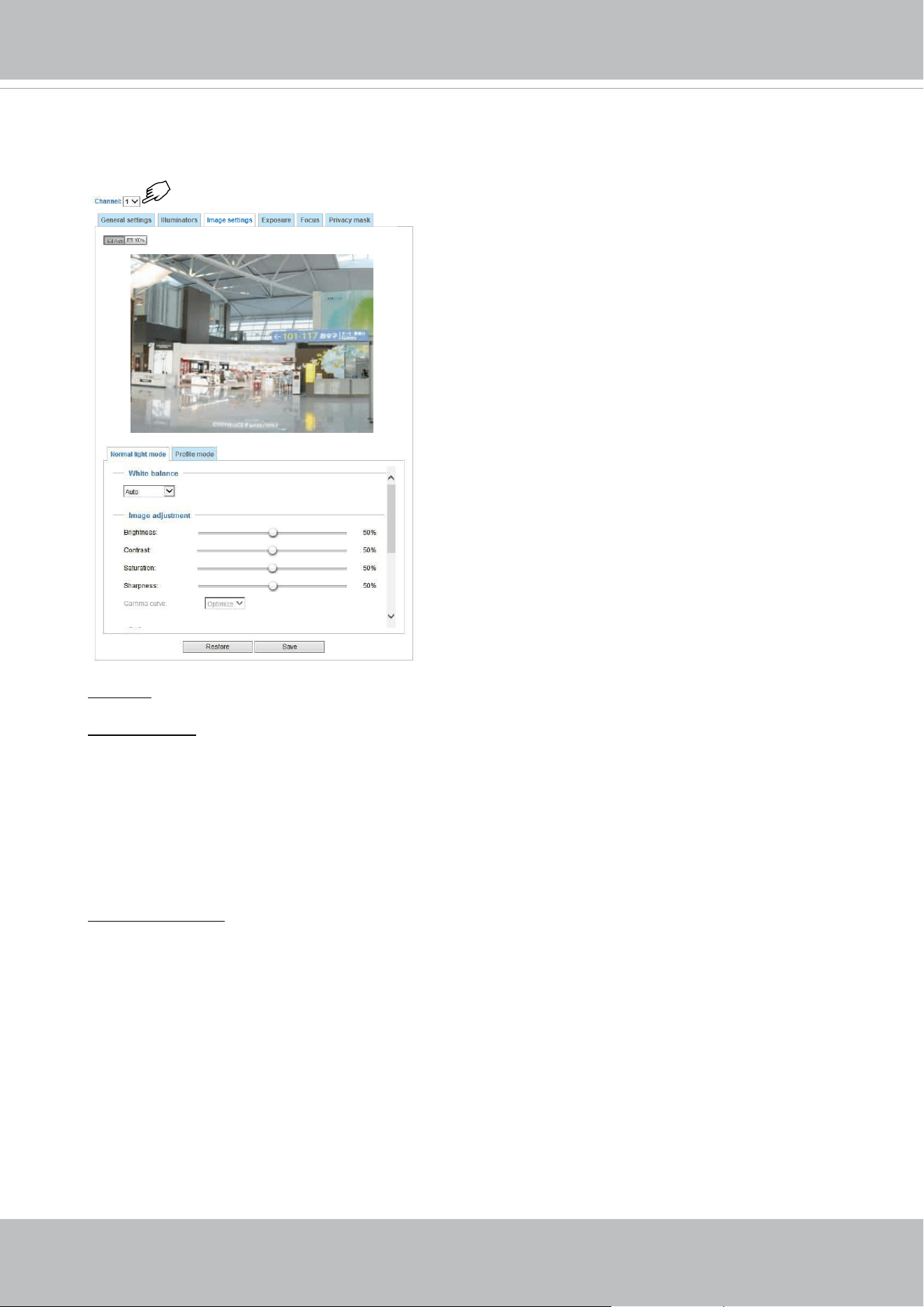
VIVOTEK
User's Manual - 75
Image settings
On this page, you can tune the White balance and Image adjustment.
Channel: Select one of the 4 Channels (sensors).
White balance: Adjust the value for the best color temperature.
■ You may follow the steps below to adjust the white balance to the best color temperature.
1. Place a sheet of paper of white or cooler-color temperature color, such as blue, in front of the
lens, then allow the Network Camera to automatically adjust the color temperature.
2. Click the On button to Fix current value and conrm the setting while the white balance is being
measured.
■ You may also manually tune the color temperature by pulling the RGain and BGain slide bars.
Image Adjustment
■ Brightness: Adjust the image brightness level, which ranges from
0% to 100%
.
■ Contrast: Adjust the image contrast level, which ranges from 0% to 100%.
■ Saturation: Adjust the image saturation level, which ranges from 0% to 100%.
■ Sharpness:
Adjust the image sharpness level, which ranges from
0% to 100%
.
■ Gamma curve:
Adjust the image sharpness level, which ranges from
0 to 0.45
.
You may let firmware Optimize your display or select a value to change the preferred level of
Gamma correction towards higher contrast or towards the higher luminance for detailed expression
for both the dark and lighted areas of an image.
This option is disabled when the WDR feature is enabled.
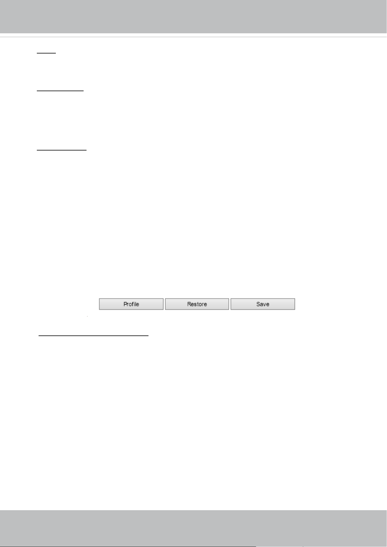
VIVOTEK
76 - User's Manual
Note that the Preview button has been cancelled, all changes made to image settings is directly
shown on screen. You can click Restore to recall the original settings without incorporating the
changes. When completed with the settings on this page, click Save to enable the setting. You
can also click on Prole mode to adjust all settings above in a tabbed window for special lighting
conditions.
Enable and apply these settings at:
Select the mode this prole to apply to: Day mode, Night mode,
or Schedule mode. Please manually enter a range of time if you choose Schedule mode. Then
check Save to take eect.
Noise reduction
■ Enable noise reduction: Check to enable noise reduction in order to reduce noises and ickers
in image. This applies to the onboard 3D Noise Reduction feature. Use the pull-down menu to
adjust the reduction strength. Note that applying this function to the video channel will consume
system computing power.
3D Noise Reduction is mostly applied in low-light conditions. When enabled in a low-light
condition with fast moving objects, trails of after-images may occur. You may then select a lower
strength level or disable the function.
Defog: Defog helps improve the visibility quality of captured image in poor weather conditions such
as smog, fog, or smoke.
Highlight mask
■
Strong light sources will be masked from the scene, and the image contrast will be strengthened.
This function is useful to prevent the spot-light eects in a high dynamic scene.
False color may be observed around the edges of strong light sources.
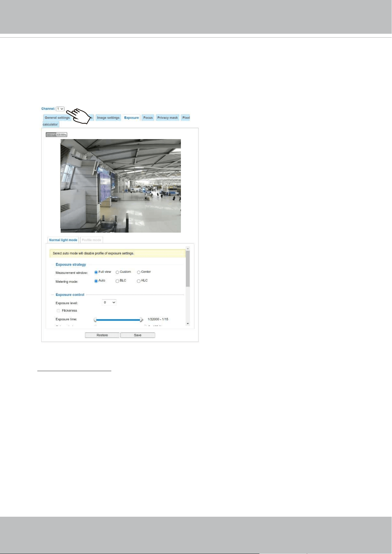
VIVOTEK
User's Manual - 77
Exposure
On this page, you can congure the Exposure measurement window, Exposure level, Exposure
mode, Exposure time, Gain control settings. You can congure two sets of Exposure settings: one
for normal situations, the other for special situations, such as the day/night/schedule mode.
Measurement Window: This function allows users to configure measurement window(s) for low
light compensation. For example, where low-light objects are posed against an extremely bright
background. You may want to exclude the bright sunlight shining through a building's corridor.
■ Full view: System calculates the full range of view and provides appropriate
light compensation.
■ Custom: This option allows you to manually add customized windows as inclusive or exclusive
regions. A total of 10 windows can be configured. Please refer to the next page for detailed
illustration.
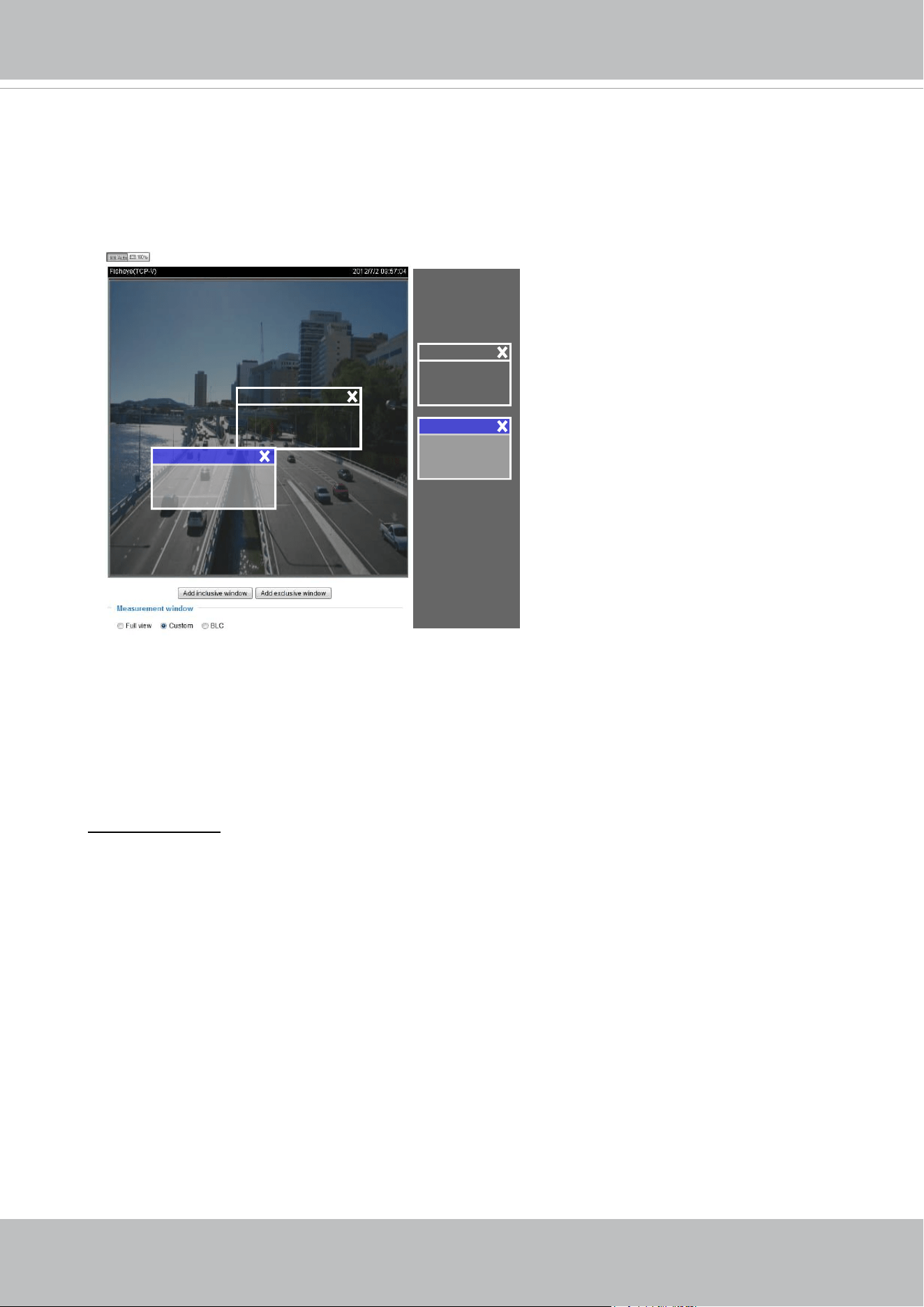
VIVOTEK
78 - User's Manual
Exposure control:
■
Exposure level: You can manually configure the Exposure level, which ranges from -2.0 to
+2.0 (dark to bright). You can click and drag the semi-circular pointers on the Exposure time
and Gain control slide bars to specify a range of shutter time and Gain control values within
which the camera can automatically tune to an optimal imaging result. You may prefer a shorter
shutter time to better capture moving objects, while a faster shutter reduces light and needs to be
compensated by electrical brightness gains.
The inclusive window refers to the “weighted window“; the exclusive window refers to “ignored
window“. It adopts the weighed averages method to calculate the value. The inclusive windows
have a higher priority. You can overlap these windows, and, if you place an exclusive window
within a larger inclusive window, the exclusive part of the overlapped windows will be deducted
from the inclusive window. An exposure value will then be calculated out of the remaining of the
inclusive window.
■ BLC (Back Light Compensation): This option will automatically add a “weighted region“ in the
middle of the window and give the necessary light compensation.
Include
Exclude
Weighted region
Ignored region
Include
Exclude
■
HLC: (Highlight Compensation). Firmware detects strong light sources and compensates on
affected spots to enhance the overall image quality. For example, the HLC helps reduce the
glares produced by spotlights or headlights.
- Flickerless:
Fixed iris models can encounter image rolling band issues when
operating under incongrous
power line frequency with uorescent lights. To solve the problem, the Flickerless mode can limit
the exposure time to 1/120 ~ 1/5 second. For the Auto iris models, when the exposure time is
limited to 1/120 ~1/5 second, iris size is automatically adjusted, and that the image brightness
is appropriately adjusted. Although the chance is rare, for Fixed iris models, when the exposure
time is limited to 1/120 ~ 1/5 second, they may encounter image over-exposure. If the Flickerless
option is selected, and users discover over-exposure from the live view, they can disable the
Flickerless option.
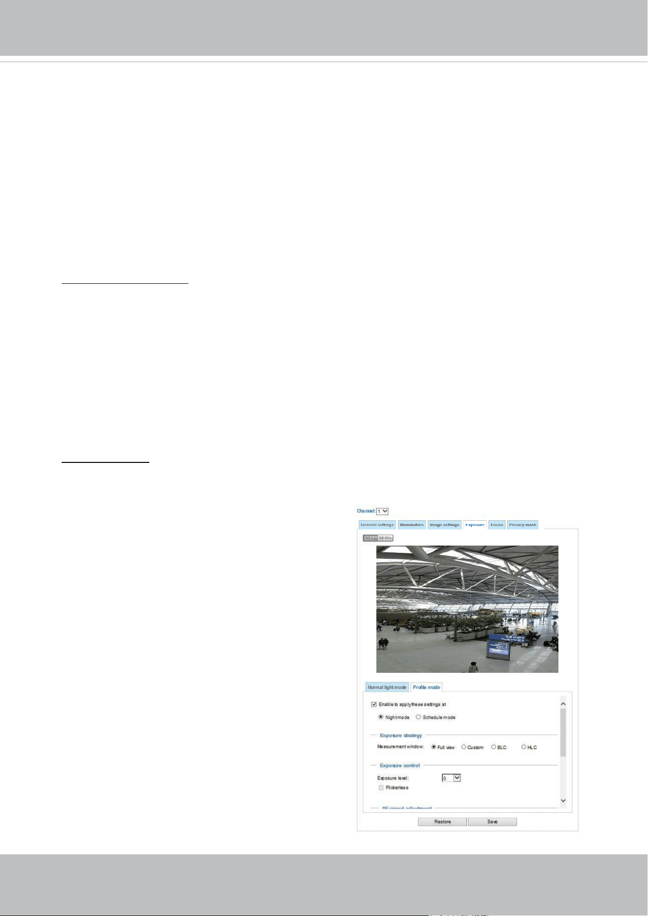
VIVOTEK
User's Manual - 79
Please follow the steps below to congure a prole:
1. Select the Prole mode tab.
2. Select the applicable mode: Night mode or
Schedule mode. Please manually enter a range of
time if you choose the Schedule mode.
3. Congure Exposure control settings in the folowing
columns. Please refer to previous dicussions for
detailed information.
4. Click Save to enable the setting and click Close to
exit the page.
If you want to congure another sensor setting for day/night/schedule mode, please click Prole to
open the Prole of exposure settings page as shown below.
Activated period:
Select the mode this prole to apply to: Night mode or Schedule mode. Please
manually enter a range of time if you choose Schedule mode. Then check Save for the conguration
to take eect.
You can click Restore to recall the original settings without incorporating the changes. When
completed with the settings on this page, click Save to enable the settings.
■
AE Speed Adjustment:
This function applies when you need to monitor fast changing lighting conditions. For example,
the camera may need to monitor a highway lane or entrance of a parking area at night where
cars passing by with their lights on can bring fast changes in light levels. The same applies if
the camera is installed on a vehicle, and when it needs to adapt to fast changes of light when
entering and leaving a tunnel.
Enable WDR enhanced:
This function allows users to identify more image details with an extreme
contrast from an object of interest with one shadowed side against a bright background, e.g., an
entrance. You may select the Enable WDR enhanced checkbox, and then adjust the strength (low,
medium, high) to reach the best image quality.
■
WDR Pro:
This refers to the Wide Dynamic Range function that enables the camera to capture details in
a high contrast environment. Use the checkbox to enable the function, and use the slide bar
to select the strength of the WDR Pro functionality, depending on the lighting condition at the
installation site. You can select a higher eect when the contrast is high (between the shaded
area and the light behind the objects).
Note that the Profile mode configuration is not
available when the IR cut filer is configured in the
Auto mode.
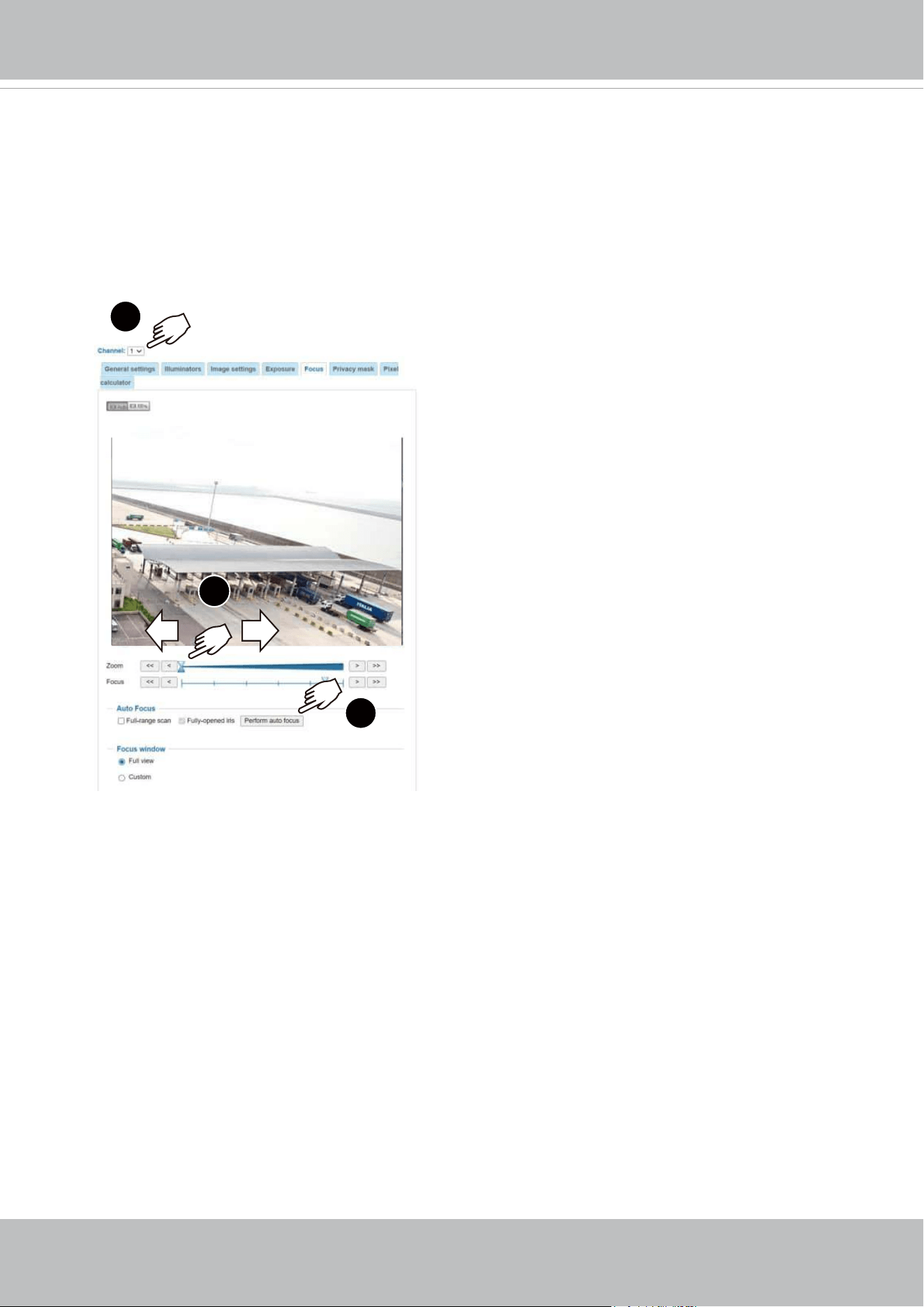
VIVOTEK
80 - User's Manual
Focus
Focus here refers to the Remote Focus, is applicable to Network Cameras that are
equipped with stepping motor lens. The automated focus adjustment function eliminates
the needs to physically adjust camera focus. In an outdoor deployment consisting of a
large number of cameras, the auto focus function can be very helpful when these cameras
become out of focus after days or weeks of operation. And that can easily result from
the effects of natural forces, e.g., shrink and expand due to a wide range of operating
temperatures and the vibration caused by wind.
Below is the procedure to perform the automated Focus function:
1. Select a Channel (one of the 4 sensors).
2. Select from the bottom of the screen whether you want to perform focus adjustment on
the Full view or within a Custom focus window. You can create a custom window and
click and drag the window to a desired position on screen.
3. You can use the Fully-opened iris checkbox (default) to increase the iris size for a
better focus adjustment result.
4. Click on the Perform auto focus button. When the Full-range scan checkbox is
selected, a full-range scan through the camera's entire focal length can take about 30
to 80 seconds. If not, the auto focus scan will only go through the length where optimal
focus may occur, and that takes about 15 to 20 seconds. In theory, best results of the
auto scan can be acquired when the camera's iris is fully open.
1
2
3
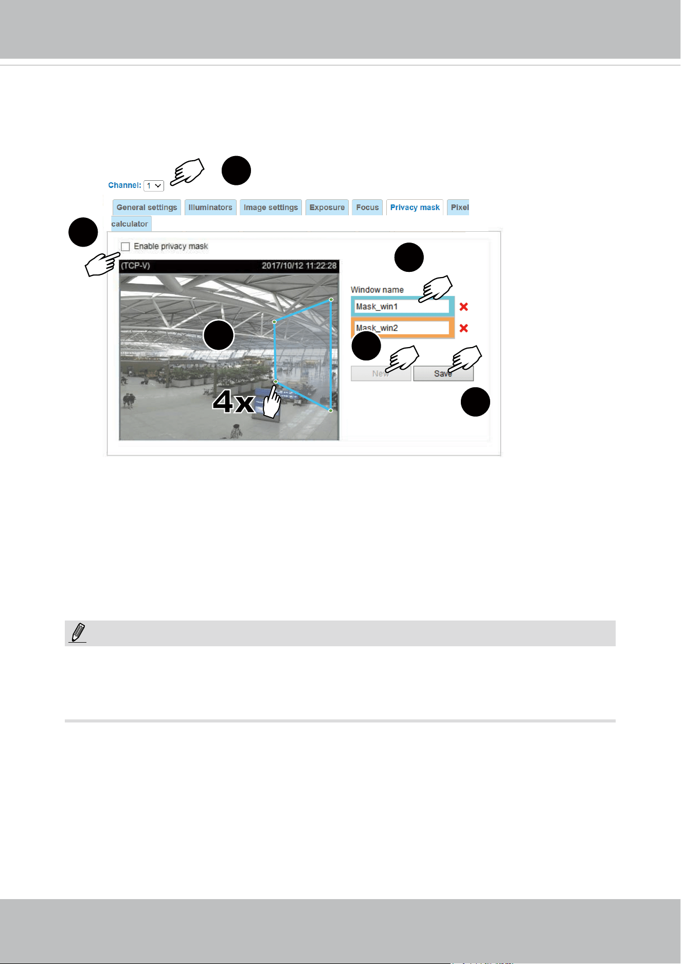
VIVOTEK
User's Manual - 81
Privacy mask
Click Privacy Mask to open the settings page. On this page, you can block out sensitive zones to
address privacy concerns.
■ To congure privacy mask windows,
1. Select a Channel (one of the 4 sensors).
2. Click New to add a new window.
3. You can use 4 mouse clicks to create a new masking window. You can pull the corner marks to
adjust the coverage.
4. Enter a Window Name, such as Neighbor's window.
5. Click Save to preserve the setting.
6. Click on the Enable privacy mask checkbox to enable this function.
6
3
2
4
5
1
NOTE:
►
Up to 5 privacy mask windows can be congured on the same screen.
► If you want to delete the
privacy mask
window, please click the ‘x’ mark on the side of window
name.
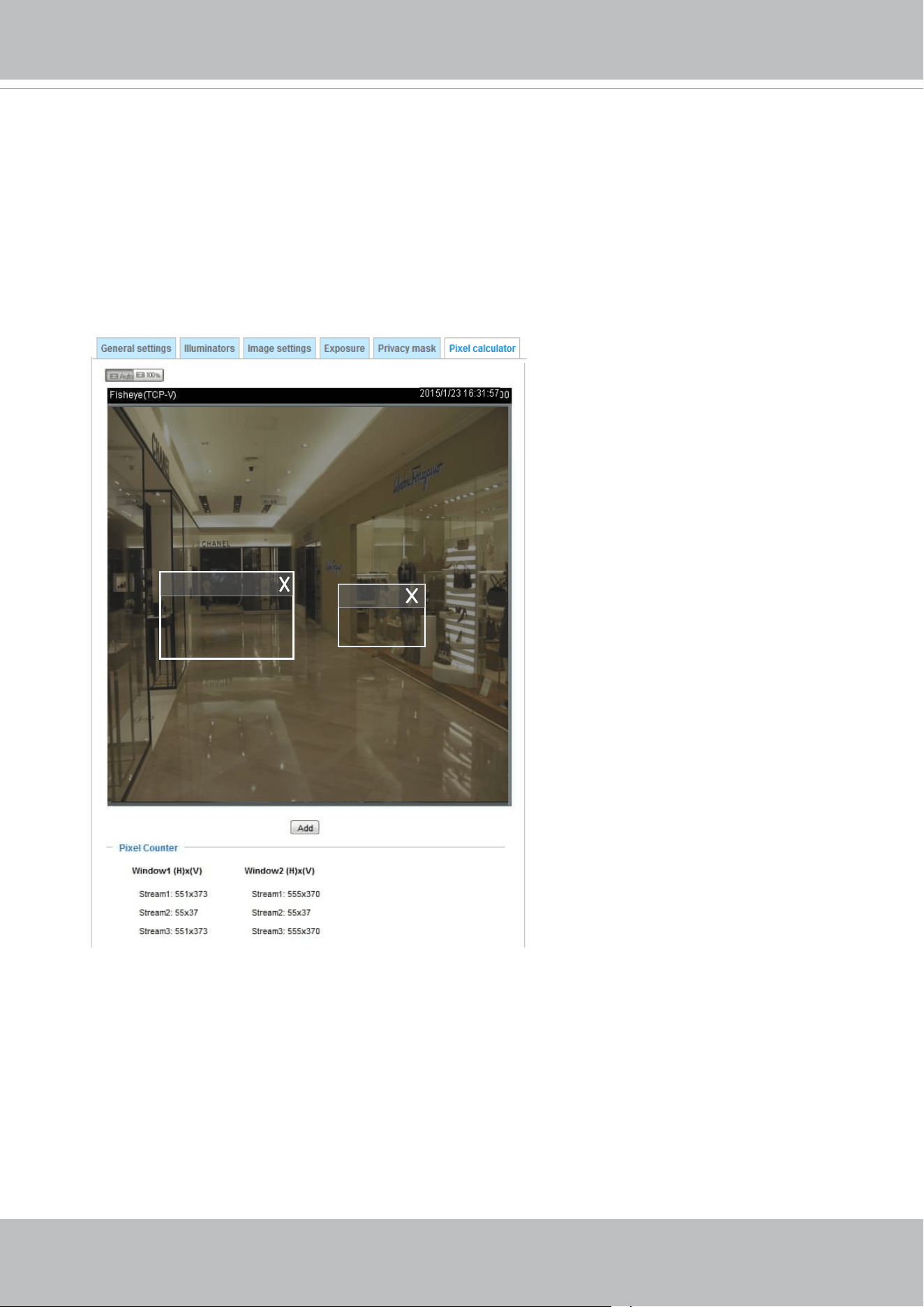
VIVOTEK
82 - User's Manual
Pixel Calculator
Click the Add button at the lower screen to create a pixel calculator window. Place your cursor on
the window to move it to an area of your interest, and change the size of window to t the area of
interest.
Once they are drawn, the numbers of pixels on the sides of windows will appear. This allows you to
calculate if your current conguration fullls a requirement, for instance, for recognizing the faces
of persons passing through a location. A facial recognition usually requires around 130 pixels per
meter or higher.
Pixel Calculator
1
2
The pixels thus calculated are listed
at the lower screen on a per-stream
basis depending on the frame size you
congured for each video stream.
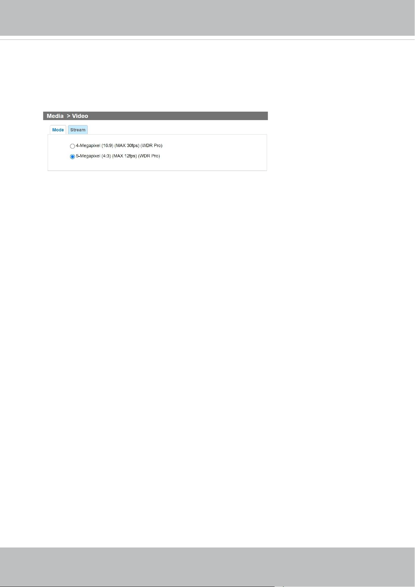
VIVOTEK
User's Manual - 83
Media > Video
Mode
The applicable video modes include:
■
5-Megapixel (4:3)(MAX 12fps) (WDR Pro): This is the full resolution at 5 megapixels in a 4:3
screen aspect ratio, with the WDR function enabled.
■
4-Megapixel (16:9)(MAX 30fps) (WDR Pro): This is the full resolution at 4 megapixels in a 16:9
screen aspect ratio, with the WDR function enabled.
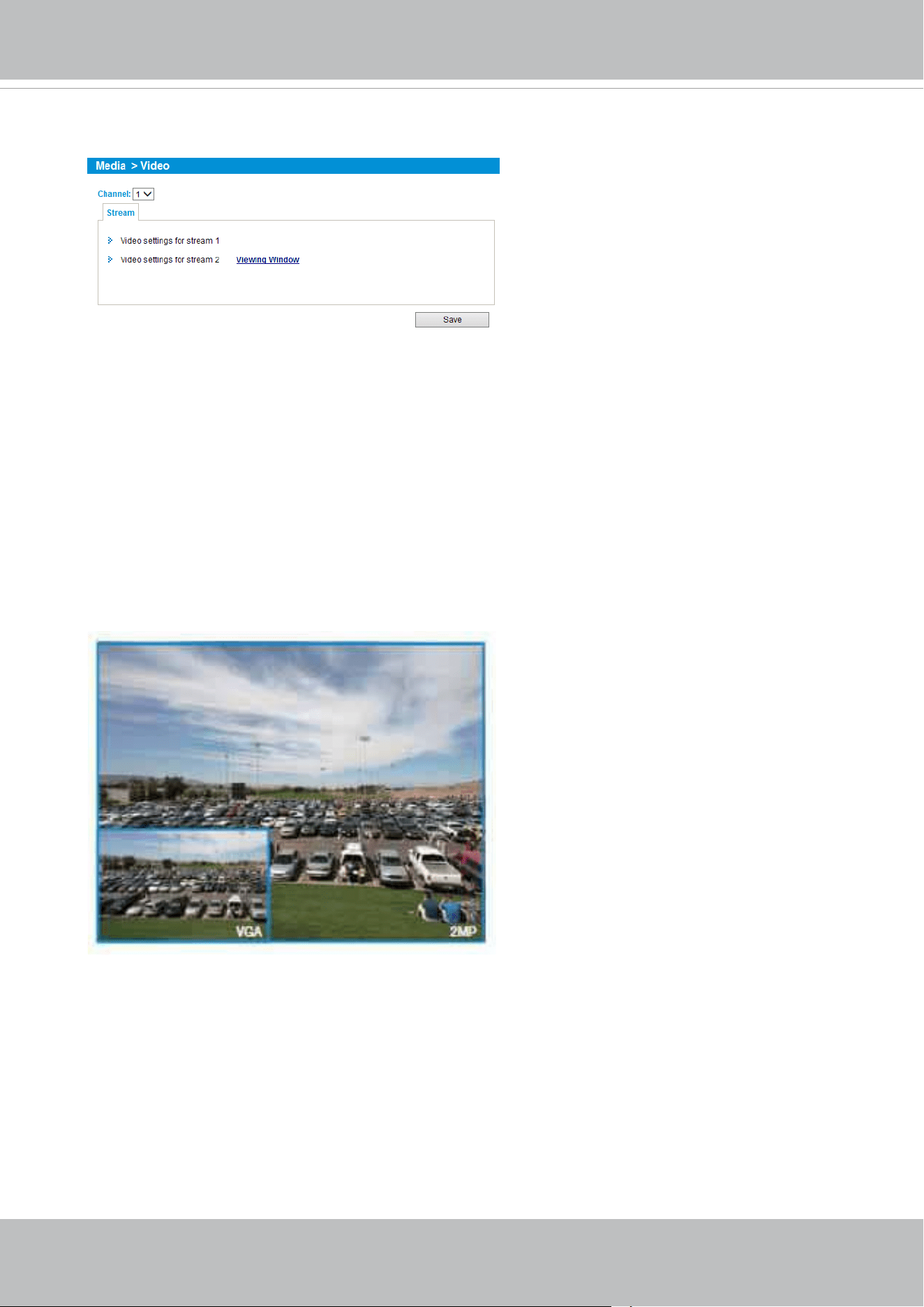
VIVOTEK
84 - User's Manual
Stream settings
This Network Camera supports multiple streams with frame sizes ranging from 448 x 320 to 2688 x
1920 pixels.
■ Stream 1: Users can dene the "Region of Interest" (viewing region) and the "Output Frame Size"
(size of the live view window).
■ Stream 2: The default frame size for Stream 2 is set to the 1280 x 960.
Click Viewing Window to open the viewing region settings page. On this page, you can congure
the Region of Interest and the Output Frame Size for a video stream. For example, you can crop
only a portion of the image that is of your interest, and thus save the bandwidth needed to transmit
the video stream. As the picture shown below, the area of your interest in a parking lot should be
the vehicles. The blue sky is of little value for the surveillance purpose.
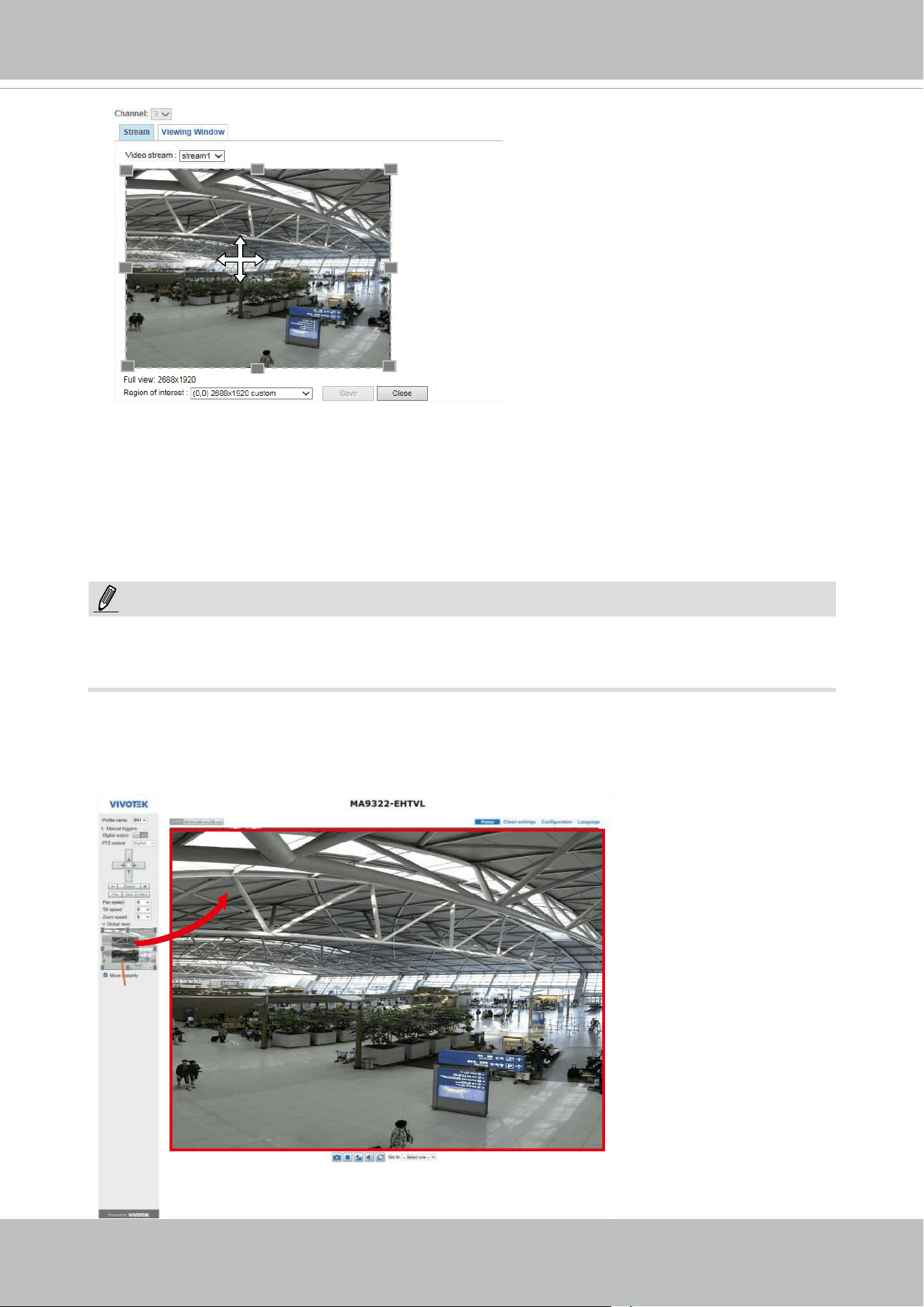
VIVOTEK
User's Manual - 85
Media > Video
► All the items in the “Region of Interest” should not be larger than the “Output Frame Size“
(current maximum resolution).
When completed with the settings in the Viewing Window, click Save to enable the settings and
click Close to exit the window. The selected Output Frame Size will immediately be applied to
the Frame size of each video stream. Then you can go back to the home page to test the e-PTZ
function. For more information about the e-PTZ function, please refer to page 133.
Output Frame Size
(Size of the Live View Window)
Region of Interest
(Viewing Region)
NOTE:
Please follow the steps below to congure the settings for a stream:
1. Select a stream for which you want to set up the viewing region.
2. Select a Region of Interest from the drop-down list. The oating frame, the same as the one
in the Gloabl View window on the home page, will resize accordingly. If you want to set up
a customized viewing region, you can also resize and drag the floating frame to a desired
position using your mouse.
3. Choose a proper Output Frame Size from the drop-down list according to the size of your
monitoring device.
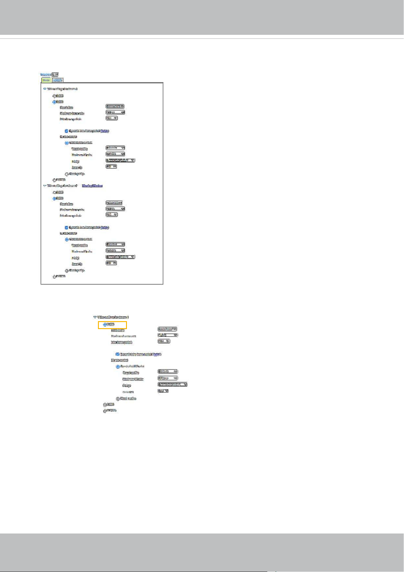
VIVOTEK
86 - User's Manual
Click the stream item to display the detailed information. The maximum frame size will follow your
settings in the above Viewing Window sections.
This Network Camera oers real-time H.265, H.264, and MJPEG compression standards (Triple
Codec) for real-time viewing. If the H.265 or H.264 mode is selected, the video is streamed via
RTSP protocol. There are several parameters through which you can adjust the video performance:
■ Frame size
You can set up different video resolutions for different viewing devices. For example, set a
smaller frame size and lower bit rate for remote viewing on mobile phones and a larger video
size and a higher bit rate for live viewing on web browsers, or recording the stream to an NVR.
Note that a larger frame size takes up more bandwidth.
■ Maximum frame rate
This limits the maximum refresh frame rate per second. Set the frame rate higher for smoother
video quality and for recognizing moving objects in the eld of view.
If the power line frequency is set to 50Hz , the frame rates are selectable at 1fps to 25fps. If the
power line frequency is set to 60Hz, the frame rates are selectable at 1fps to 30fps. You can also
select Customize and manually enter a value.
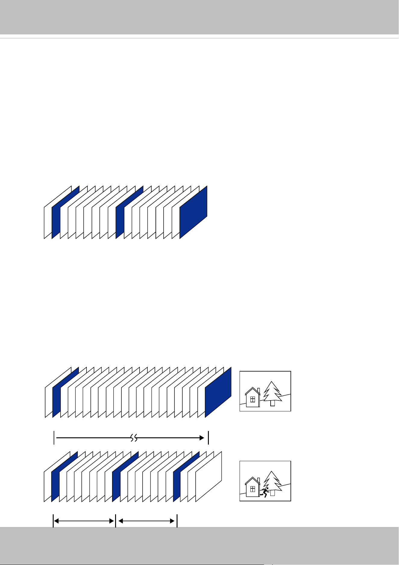
VIVOTEK
User's Manual - 87
■ Intra frame period
Determine how often for firmware to plant an I frame. The shorter the duration, the
more likely you will get better video quality, but at the cost of higher network bandwidth
consumption. Select the intra frame period from the following durations: 1/4 second, 1/2
second, 1 second, 2 seconds, 3 seconds, and 4 seconds.
■ Dynamic Intra frame period
High quality motion codecs, such as H.264, utilize the redundancies between video frames to
deliver video streams at a balance of quality and bit rate.
The encoding parameters are summarized and illustrated below. The I-frames are completely
self-referential and they are largest in size. The P-frames are predicted frames. The encoder
refers to the previous I- or P-frames for redundant image information.
P I P P P P P P P P P P P P P P P P P P P I
P I P P P P P P P I P P P P P P P I
Static scene
Activities
P P P
P I P P P P P P P I P P P P P P P I
By dynamically prolonging the intervals for I-frames insertion to up to 10 seconds, the bit rates
required for streaming a video can be tremendously reduced. When streaming a video of a
static scene, the Dynamic Intra frame feature can save up to 53% of bandwidth. The amount of
bandwidth thus saved is also determined by the activities in the eld of view. If activities occur
in the scene, rmware automatically shortens the I-frame insertion intervals in order to maintain
image quality. In the low light or night conditions, the P-frames can have a larger size due to the
noises, and hence the bandwidth saving eect is also reduced.
Streaming a typical 2MP scene normally requires 3~4Mb/s of bandwidth. With the Dynamic Intra
frame function, the bandwidth for streaming a medium-trac scene can be reduced to 2~3Mb/s,
and during the no-trac period of time, down to 500kb/s.
H.264/265 Frame Types
Dynamic Intra Frame w/
static scenes
Dynamic Intra Frame w/
activities in scenes
Smart stream III
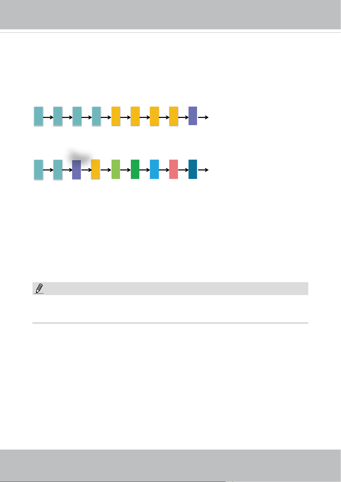
VIVOTEK
88 - User's Manual
With the H.265 codec in an optimal scenario and when Dynamic Intra frame is combined with
the Smart Stream function, an 80% of bandwidth saving can be achieved compared with using
H.264 without enabling these bandwidth-saving features.
■ Smart FPS
In a static scene, the algorithm puts old frames in queue when no motions occur in scene. When
motions occur, the encoding returns to normal to deliver real-time streaming.
f1 f1 f1
f1
f5 f5 f5 f5 f9
f1 f1
f3
f4 f5 f6 f7 f8 f9
Motions Occur.
By queuing the old frames from a static scene, both the computing efforts and the size of P
frames are reduced. It is benecial for keeping up with the frame rate requirements.
A default frame dierence threshold, 1%, is embedded in rmware for returning from Smart FPS
to normal encoding when motions occur.
Comparing with Smart Stream II, Smart Stream III has two more congurable options:
Smart Q,
and
Smart FPS.
NOTE:

VIVOTEK
User's Manual - 89
■
Smart codec eectively reduces the quality of the whole or the non-interested areas
on a screen and therefore reduces the bandwidth consumed.
X
ROI_0
X
ROI_0
ROI
non-interested
You can manually specify the video quality for the foreground and the background
areas.
Select an operation mode if Smart codec is preferred.
- Auto tracking: The Auto mode congures the whole screen into the non-interested
area. The video quality of part of the screen returns to normal when one or
more objects move in that area. The remainder of the screen where there are
no moving objects (no pixel changes) will still be transmitted in low-quality
format.
- Manual: The Manual mode allows you to configure 3 ROI windows (Region of
Interest, with Foreground quality) on the screen. Areas not included in any
ROI windows will be considered as the non-interested areas. The details in
the ROI areas will be transmitted in a higher-quality video format.
As illustrated below, the upper screen may contain little details of your
interest, while the sidewalk on the lower screen is included in an ROI
window.
Slide bar to the right - higher quality in the ROI
areas
Slide bar to the left - higher quality in the non-ROI
areas.
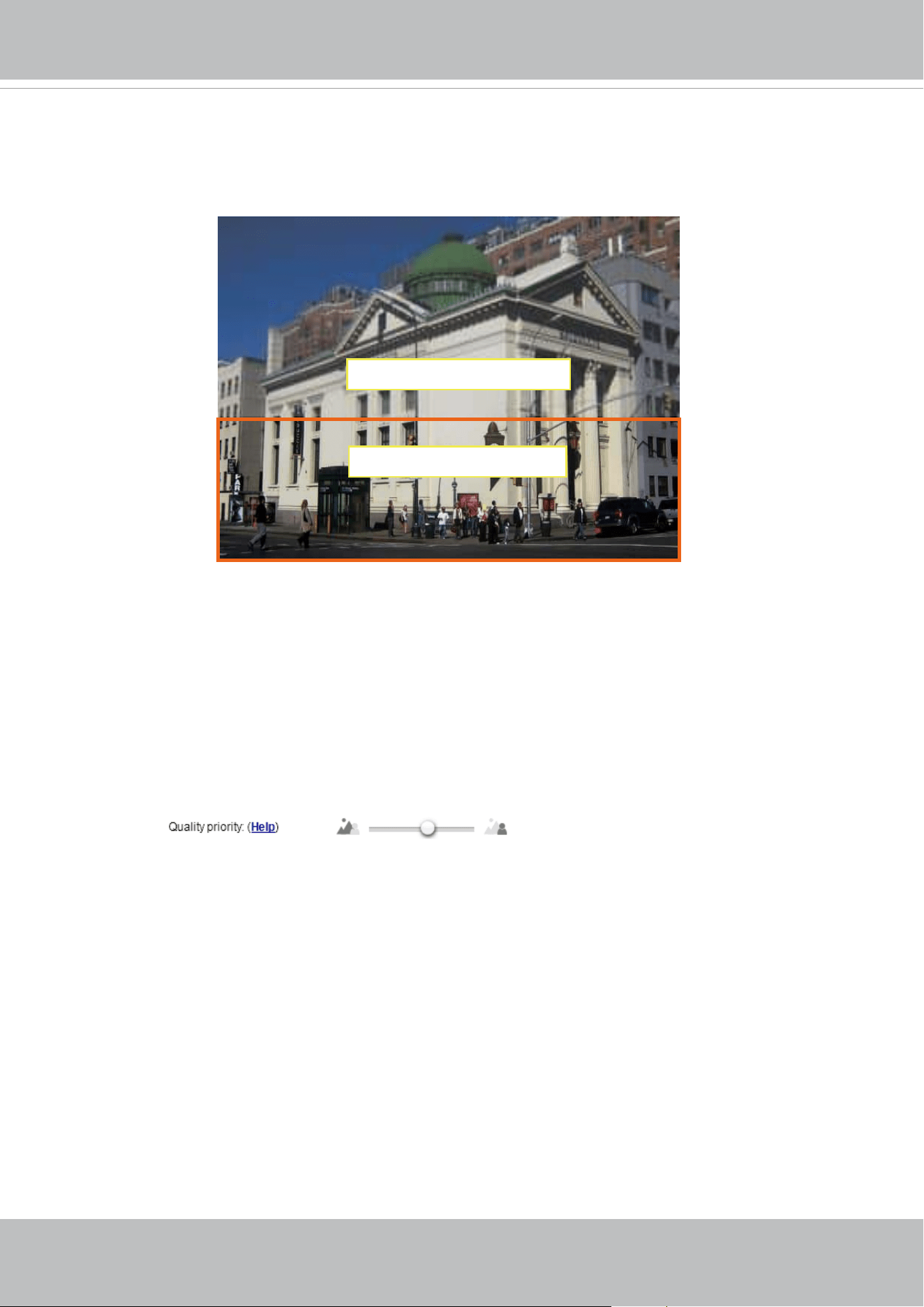
VIVOTEK
90 - User's Manual
ROI: higher-quality
non-ROI: lower-quality
As the result, the lower screen is constantly displayed in high details,
while the upper half is transmitted using a lower-quality format. Although
the upper half is transmitted using a lower quality format, you still have an
awareness of what is happening on the whole screen.
- Hybrid: The major difference between the “Manual” mode and the “Hybrid”
mode is that:
In the “Hybrid“ mode, any objects entering the non-interested area will
restore the video quality of the moving objects and the area around
them. The video quality of the associated non-interested area is
immediately restored to normal to cover the moving objects.
In the “Manual” mode, the non-interested area is always transmitted
using a low-quality format regardless of the activities inside.
You should also select the Maximum bit rate from the pull-down menu as the
threshold to contain the bandwidth consumption for both the high- and low-
quality video sections in a smart stream.
- Quality priority: Use the slide bar to tune the quality contrast between the ROI
and non-interested areas.
The farther the slide bar button is to the right, the higher the image
quality of the ROI areas. On the contrary, the farther the slide bar button
to the left, the higher the image quality of the non-interested area.
In this way, you may set up an ROI window as a privacy mask by
covering a protected area using an ROI window, while the remaining
screen become the non-interested area. You may then configure the
non-interested area to have a high image quality, or vice versa.

VIVOTEK
User's Manual - 91
■ B
it rate control
Constrained bit rate:
A complex scene generally produces a larger le size, meaning that higher bandwidth
will be needed for data transmission. The bandwidth utilization is configurable to
match a selected level, resulting in mutable video quality performance. The bit rates
are selectable at the following rates: 20Kbps, 30Kbps, 40Kbps, 50Kbps, 64Kbps,
128Kbps, 256Kbps, 512Kbps, 768Kbps, 1Mbps, 2Mbps, 3Mbps, 4Mbps, 6Mbps,
8Mbps, 10Mbps, 12Mbps, 14Mbps, ~ to 80Mbps. You can also select Customize
and manually enter a value up to 40Mbps.
• - Target quality: Select a desired quality ranging from Medium to Excellent
- Maximum bit rate: select a bit rate from the pull-down menu. The bit rate ranges
from 20kbps to a maximum of 40Mbps. The bit rate then becomes the Average or
Upper bound bit rate number. The Network Camera will strive to deliver video streams
around or within the bit rate limitation you impose.
- Policy: If Frame Rate Priority is selected, the Network Camera will try to maintain
the frame rate per second performance, while the image quality will be compromised.
If Image quality priority is selected, the Network Camera may drop some video
frames in order to maintain image quality.
Smart Q: Select ON or OFF to enable or disable the feature. Smart Q is scene-aware.
The Smart Q reduces frame size and bit rate consumption through the following:
■
Dynamically adjusting the image quality for scenes in dierent luminosities while
keeping the same imaging quality in low light.
■
Endorsing dierent qualities for the I frames and P frames.
■ Dividing a single frame into dierent sections, and giving these sections dierent
quality values. For a highly complex image section (high frequency area), such
as an area with dense vegetation, screen windows, or repeated patterns (wall
paper), having a lower quality actually poses little eects on human eyes.

VIVOTEK
92 - User's Manual
Maximum bit rate: With the guaranteed image quality, you might still want to place
a bit rate limitation to control the size of video streams for bandwidth and storage
concerns. The congurable bit rate starts from 1Mbps to 40Mbps.
The Maximum bit rate setting in the Fixed quality configuration can ensure a
reasonable and limited use of network bandwidth. For example, in low light conditions
where a Fixed quality setting is applied, video packet sizes can tremendously
increase when noises are produced with electrical gains.
You may also manually enter a bit rate number by selecting the Customized option.
Fixed quality:
On the other hand, if Fixed quality is selected, all frames are transmitted with the
same quality; bandwidth utilization is therefore unpredictable. The video quality
can be adjusted to the following settings: Medium, Standard, Good, Detailed, and
Excellent. You can also select Customize and manually enter a value.
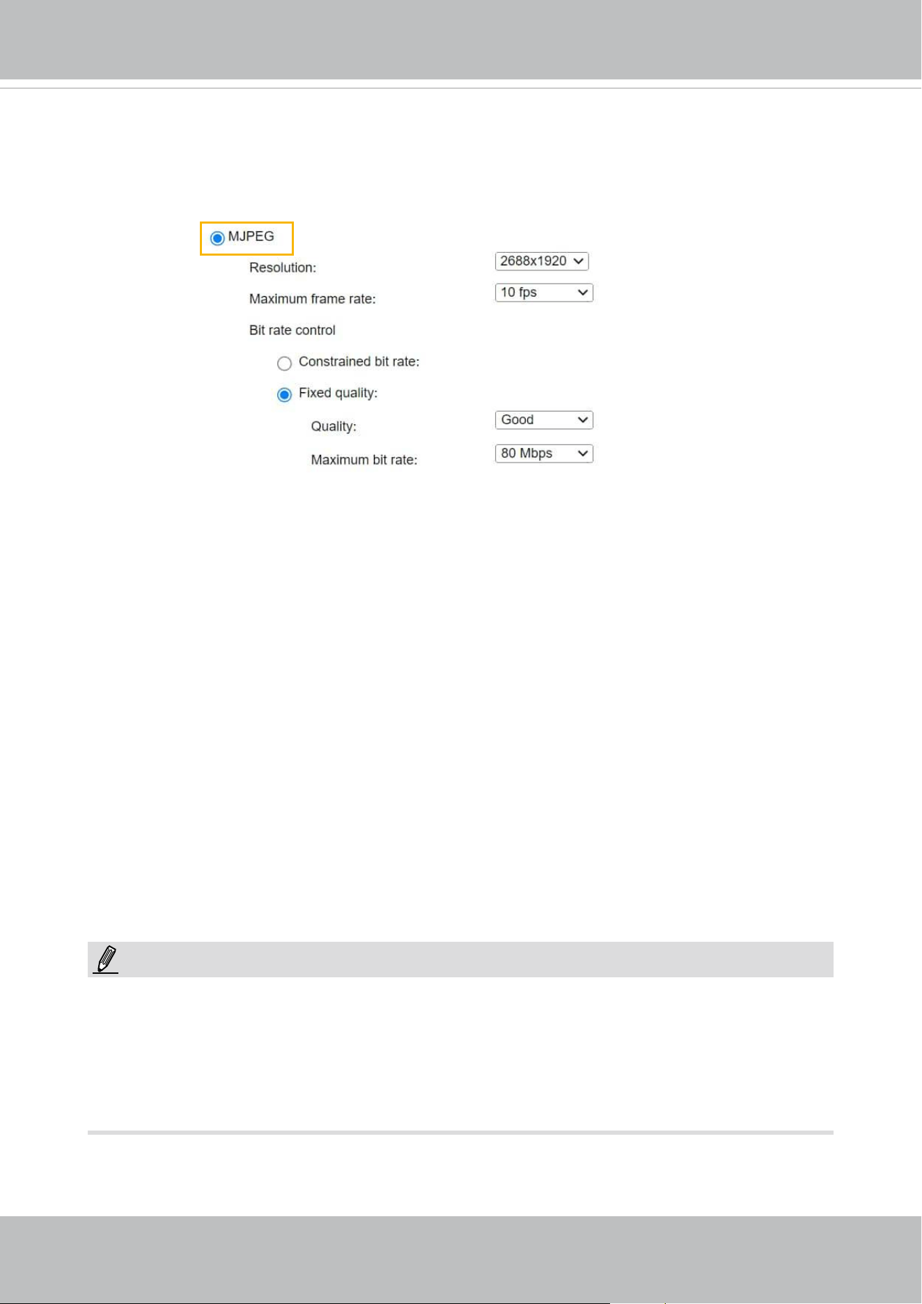
VIVOTEK
User's Manual - 93
If the JPEG mode is selected, the Network Camera sends consecutive JPEG images to the client,
producing a moving eect similar to a lmstrip. Every single JPEG image transmitted guarantees
the same image quality, which in turn comes at the expense of variable bandwidth usage. Because
the media contents are a combination of JPEG images, no audio data is transmitted to the client.
There are three parameters provided in MJPEG mode to control the video performance:
■ Frame size
You can set up dierent video resolution for dierent viewing devices. For example, set a smaller
frame size and lower bit rate for remote viewing on mobile phones and a larger video size and
a higher bit rate for live viewing on web browsers. Note that a larger frame size takes up more
bandwidth.
■ Maximum frame rate
This limits the maximum refresh frame rate per second. Set the frame rate higher for smoother
video quality.
If the power line frequency is set to 50Hz, the frame rates are selectable at 1fps, 2fps, 3fps,
5fps, 7fps, 10fps, and up to 25fps. If the power line frequency is set to 60Hz, the frame rates are
selectable at 1fps, 2fps, 3fps, 5fps, 7fps, 10fps, and up to 30fps. You can also select Customize
and manually enter a value. The frame rate will decrease if you select a higher resolution.
■ Video quality
Refer to the previous page setting an average or upper bound threshold for controlling the
bandwidth consumed for transmitting motion jpegs. The conguration method is identical to that
for H.264.
For Constant Bit Rate and other settings, refer to the previous page for details.
►
Video quality and xed quality refers to the compression rate, so a lower value will produce higher
quality.
►
Converting high-quality video may signicantly increase the CPU loading, and you may encounter
streaming disconnection or video loss while capturing a complicated scene. In the event of
occurance, we suggest you customize a lower video resolution or reduce the frame rate to obtain
smooth video.
NOTE:
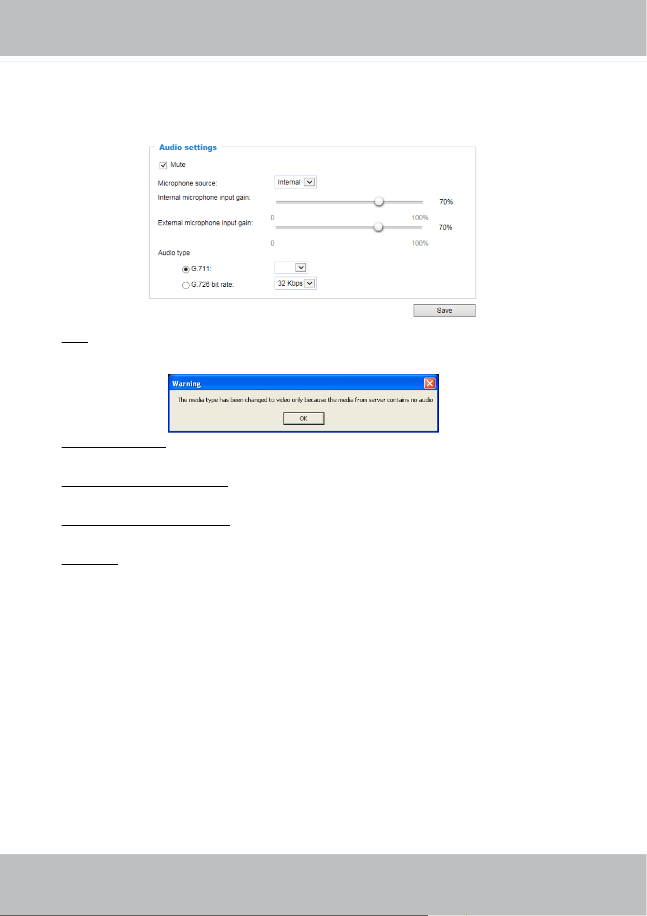
VIVOTEK
94 - User's Manual
Media > Audio
Audio Settings
Mute: Select this option to disable audio transmission from the Network Camera to all clients. Note
that if muted, no audio data will be transmitted even if audio transmission is enabled on the Client
Settings page. In that case, the following message is displayed:
Microphone source: Select the source of audio input as the onboard microphone (on the dome
cover), or the external microphone you connected via the I/O combo cable.
Internal microphone input gain: Select the gain of the external audio input according to ambient
conditions. Adjust the gain from 0% to 100%.
External microphone input gain: Select the gain of the external audio input according to ambient
conditions. Adjust the gain from 0% to 100%.
Audio type: Select audio codec and the sampling bit rate .
■ G.711 also provides good sound quality and requires about 64Kbps. Select pcmu (μ-Law) or
pcma (A-Law) mode.
■ G.726 is a speech codec standard covering voice transmission at rates of 16, 24, 32, and 40kbit/
s.
When completed with the settings on this page, click Save to enable the settings.
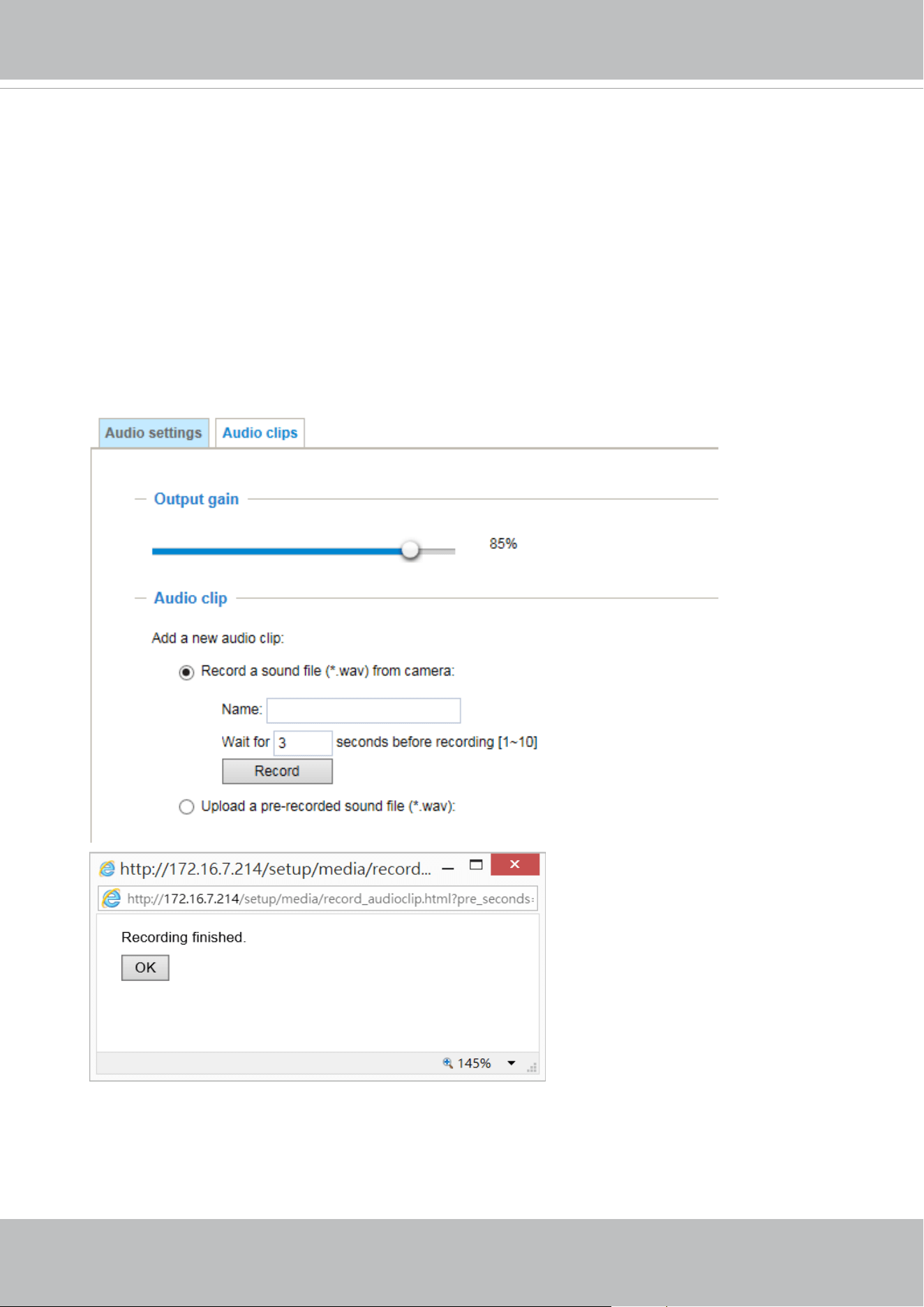
VIVOTEK
User's Manual - 95
Audio clips
■ Output gain: Use the slide bar to change the audio output gains value.
■ Audio clip: When the camera's audio input is connected to a microphone, you can record a short
period of audio recordings (1 to 10 seconds). You can also use the camera's embedded microphone to
record an audio clip, if available. Because the memory space is limited, a recording count down will be
available on screen.
You can also upload an audio file to the camera's flash memory. With amplified speakers, you can
playback the audio, e.g., to deter an intruder. A maximum of 2 audio clips in wav format are supported.
The maximum size of the audio le to be uploaded is 2,000Kbytes.
The voice alert is enabled in the Event settings > action > Play Audio Clip. The action c a n b e
associated with triggering conditions.
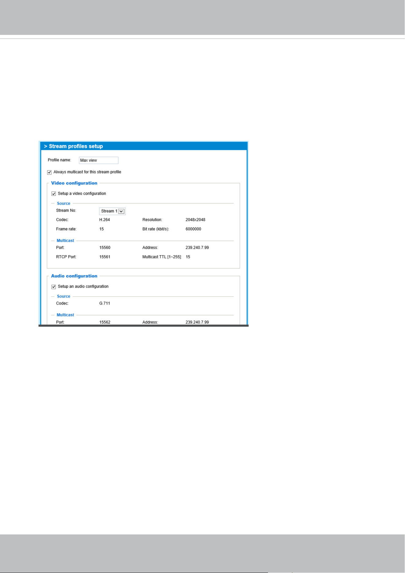
VIVOTEK
96 - User's Manual
Media proles
You can congure a dierent video stream for each of the 3 default proles, Max. view,
Recording, Live view, and App.
The related video stream information will display, including stream number, resolution,
codec used, frame rate, etc. The Multicast port number, and address for video, audio, and
Metadata conguration will also be listed.
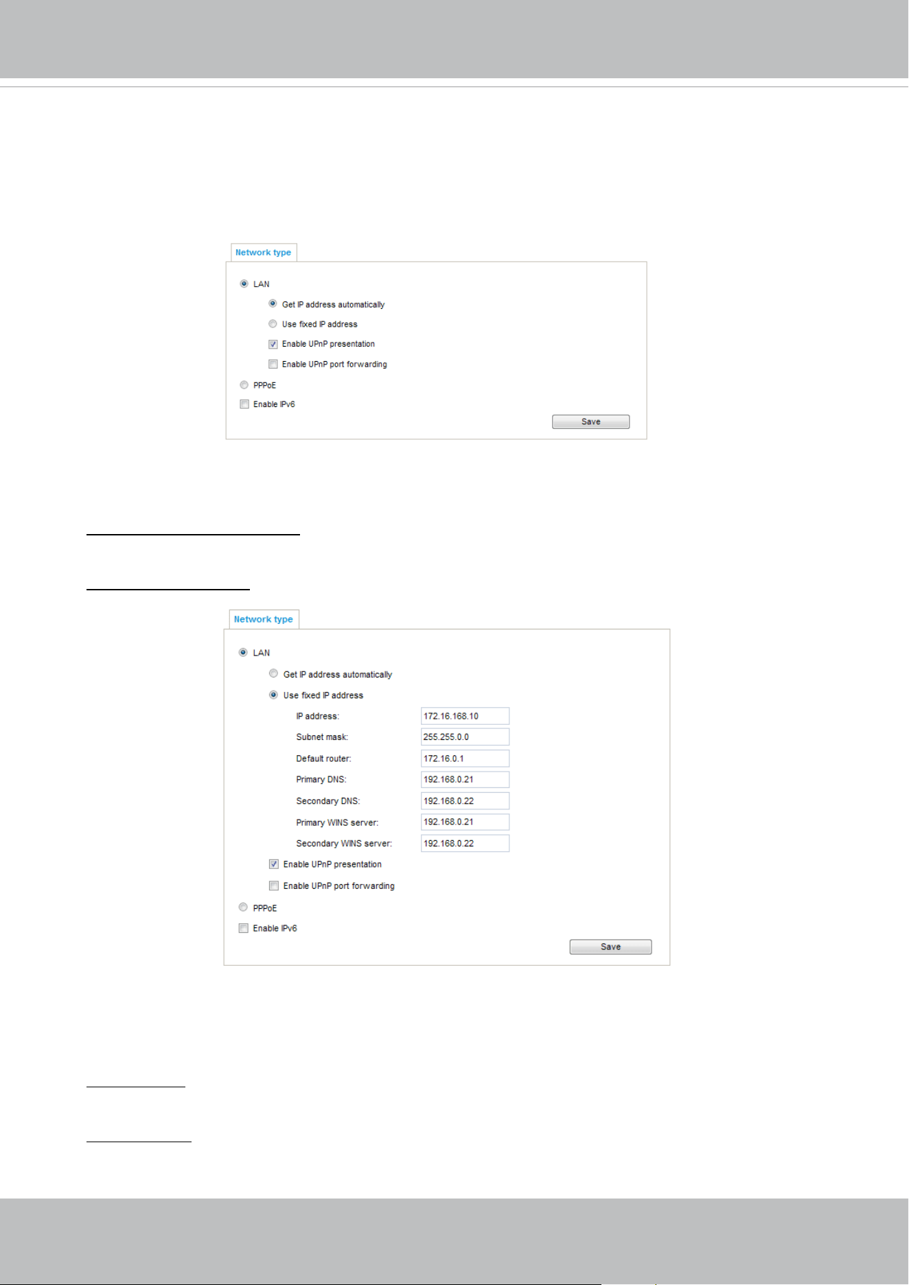
VIVOTEK
User's Manual - 97
Network > General settings
This section explains how to configure a wired network connection for the Network
Camera.
Network Type
LAN
Select this option when the Network Camera is deployed on a local area network (LAN) and is
intended to be accessed by local computers. The default setting for the Network Type is LAN.
Please rememer to click on the Save button when you complete the Network setting.
Get IP address automatically: Select this option to obtain an available dynamic IP address assigned
by the DHCP server each time the camera is connected to the LAN.
Use fixed IP address: Select this option to manually assign a static IP address to the Network
Camera.
1. You can make use of VIVOTEK Installation Wizard 2 on the software CD to easily set up the
Network Camera on LAN. Please refer to Software Installation on page 23 for details.
2. Enter the Static IP, Subnet mask, Default router, and Primary DNS provided by your ISP or
network administrator.
Subnet mask: This is used to determine if the destination is in the same subnet. The default value
is “255.255.255.0”.
Default router: This is the gateway used to forward frames to destinations in a different subnet.
Invalid router setting will disable the transmission to destinations across dierent subnets.
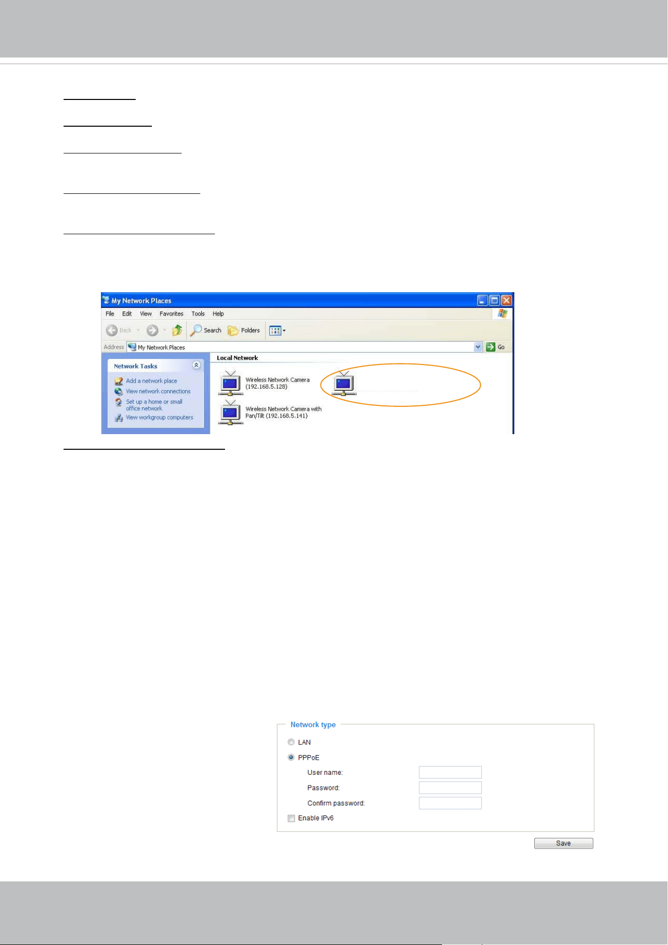
VIVOTEK
98 - User's Manual
Primary DNS: The primary domain name server that translates hostnames into IP addresses.
Secondary DNS: Secondary domain name server that backups the Primary DNS.
Primary WINS server: The primary WINS server that maintains the database of computer names
and IP addresses.
Secondary WINS server: The secondary WINS server that maintains the database of computer
names and IP addresses.
Enable UPnP presentation: Select this option to enable UPnP
TM
presentation for your Network
Camera so that whenever a Network Camera is presented to the LAN, the shortcuts to connected
Network Cameras will be listed in My Network Places. You can click the shortcut to link to the web
browser. Currently, UPnP
TM
is supported by Windows XP or later. Note that to utilize this feature,
please make sure the UPnP
TM
component is installed on your computer.
Enable UPnP port forwarding: To access the Network Camera from the Internet, select this option
to allow the Network Camera to open ports automatically on the router so that video streams can
be sent out from a LAN. To utilize of this feature, make sure that your router supports UPnP
TM
and
it is activated.
PPPoE (Point-to-point over Ethernet)
Select this option to congure your Network Camera to make it accessible from anywhere as long
as there is an Internet connection. Note that to utilize this feature, it requires an account provided
by your ISP.
Follow the steps below to acquire your Network Camera’s public IP address.
1. Set up the Network Camera on the LAN.
2. Go to Conguration > Event > Event settings > Add server (please refer to Add server on page
142) to add a new email or FTP server.
3. Go to Conguration > Event > Event settings > Add media (please refer to Add media on page
150).
Select System log so that you will receive the system log in TXT le format which contains the
Network Camera’s public IP address in your email or on the FTP server.
4. Go to Conguration > Network > General settings > Network type. Select PPPoE and enter the
user name and password provided by your ISP. Click Save to enable the setting.
5. The Network Camera will reboot.
6. Disconnect the power to the Network Camera; remove it from the LAN environment.
Mega-pixel Network Camera (192.168.5.151)
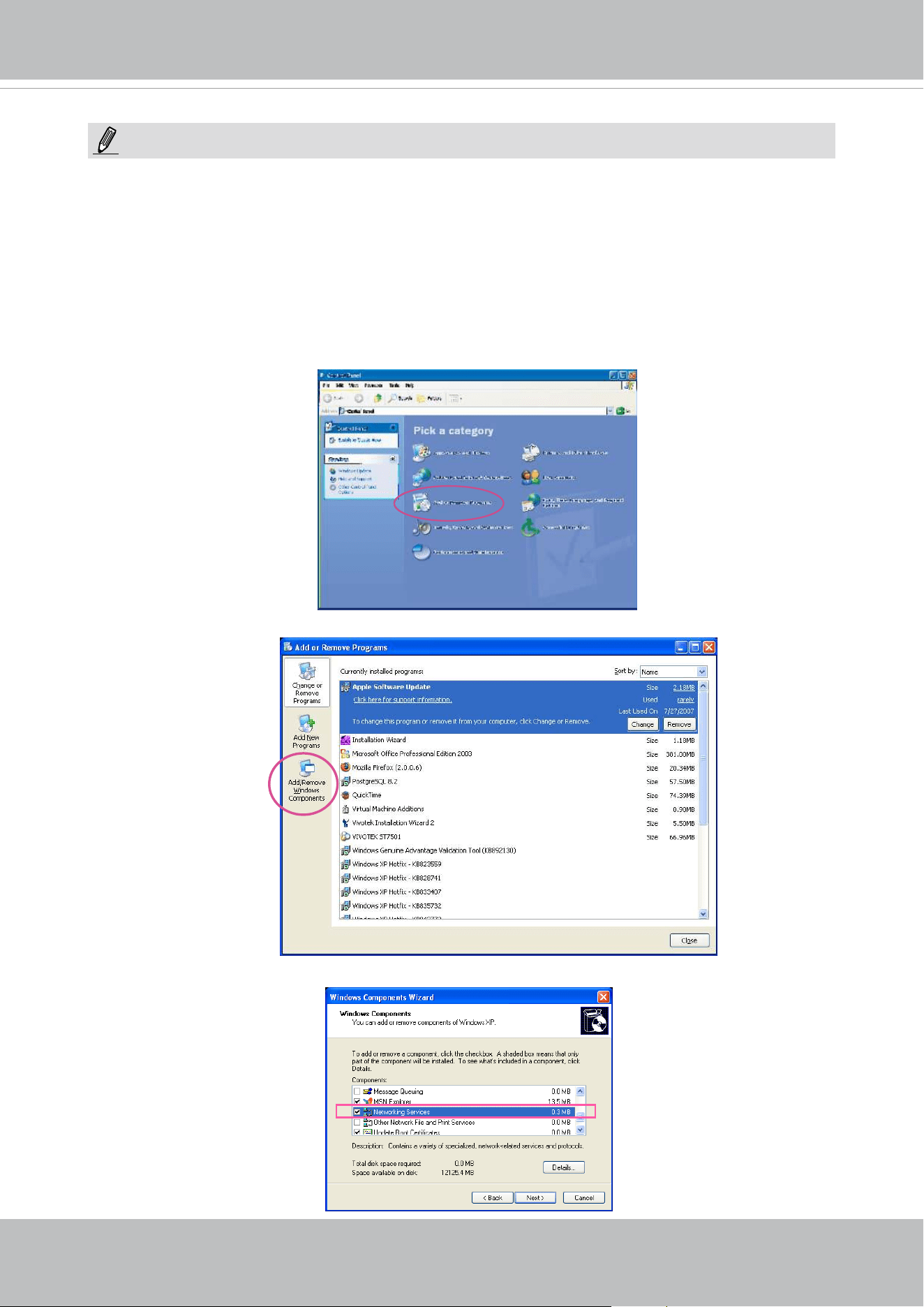
VIVOTEK
User's Manual - 99
► If the default ports are already used by other devices connected to the same router, the Network
Camera will select other ports for the Network Camera.
► If UPnP
TM
is not supported by your router, you will see the following message:
Error: Router does not support UPnP port forwarding.
► Steps to enable the UPnP
TM
user interface on your computer:
Note that you must log on to the computer as a system administrator to install the UPnP
TM
components.
1. Go to Start, click Control Panel, then click Add or Remove Programs.
2. In the Add or Remove Programs dialog box, click Add/Remove Windows Components.
3.
In the Windows Components Wizard dialog box, select Networking Services and click
Details.
NOTE:
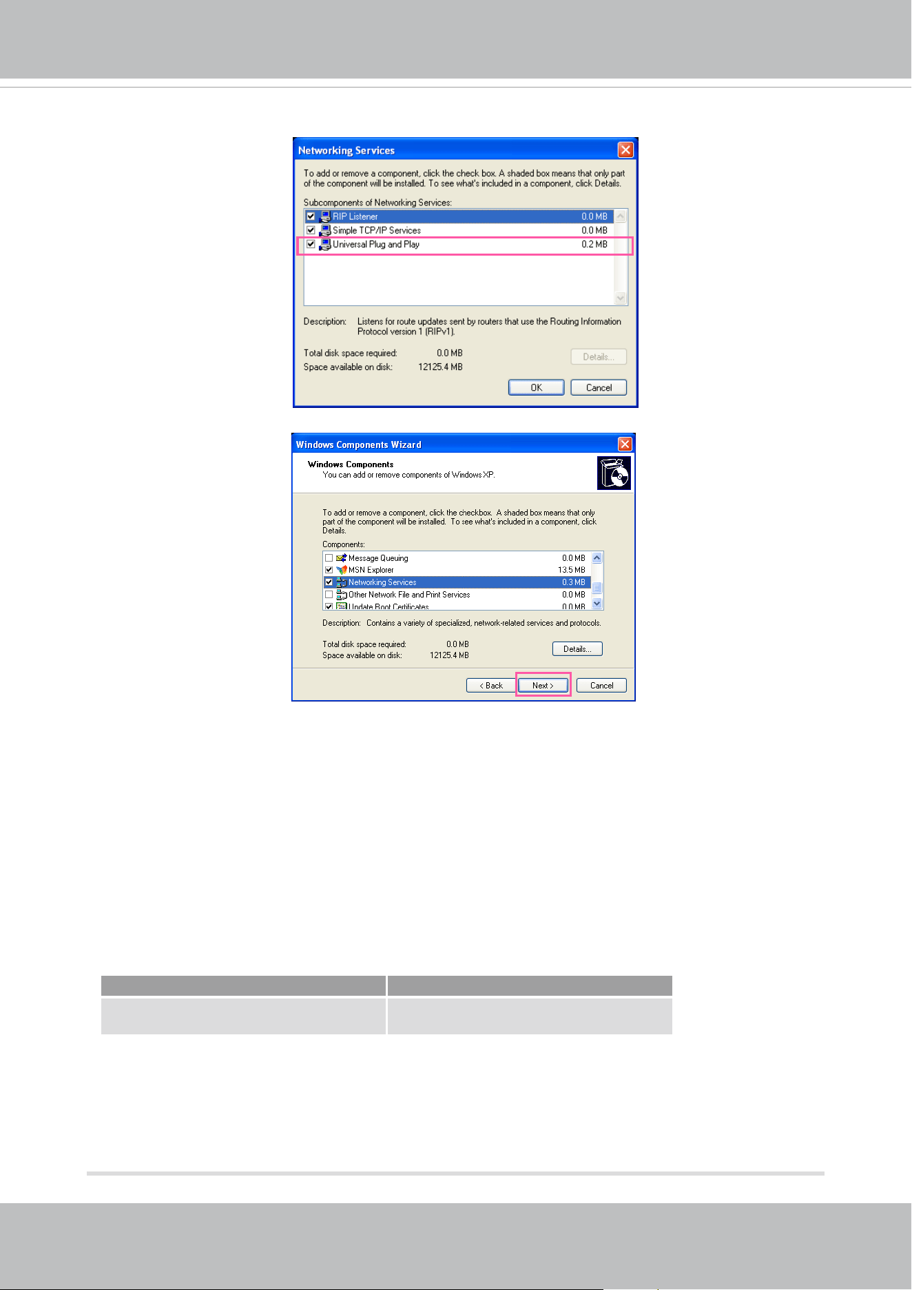
VIVOTEK
100 - User's Manual
4. In the Networking Services dialog box, select Universal Plug and Play and click OK.
5. Click Next in the following window.
6. Click Finish. UPnP
TM
is enabled.
► How does UPnP
TM
work?
UPnP
TM
networking technology provides automatic IP configuration and dynamic discovery of
devices added to a network. Services and capabilities oered by networked devices, such as
printing and file sharing, are available among each other without the need for cumbersome
network conguration. In the case of Network Cameras, you will see Network Camera shortcuts
under My Network Places.
► Enabling UPnP port forwarding allows the Network Camera to open a secondary HTTP port on
the router-not HTTP port-meaning that you have to add the secondary HTTP port number to the
Network Camera’s public address in order to access the Network Camera from the Internet. For
example, when the HTTP port is set to 80 and the secondary HTTP port is set to 8080, refer to
the list below for the Network Camera’s IP address.
From the Internet In LAN
http://203.67.124.123:8080 http://192.168.4.160 or
http://192.168.4.160:8080
► If the PPPoE settings are incorrectly congured or the Internet access is not working, restore
the Network Camera to factory default; please refer to Restore on page 68 for details. After the
Network Camera is reset to factory default, it will be accessible on the LAN.
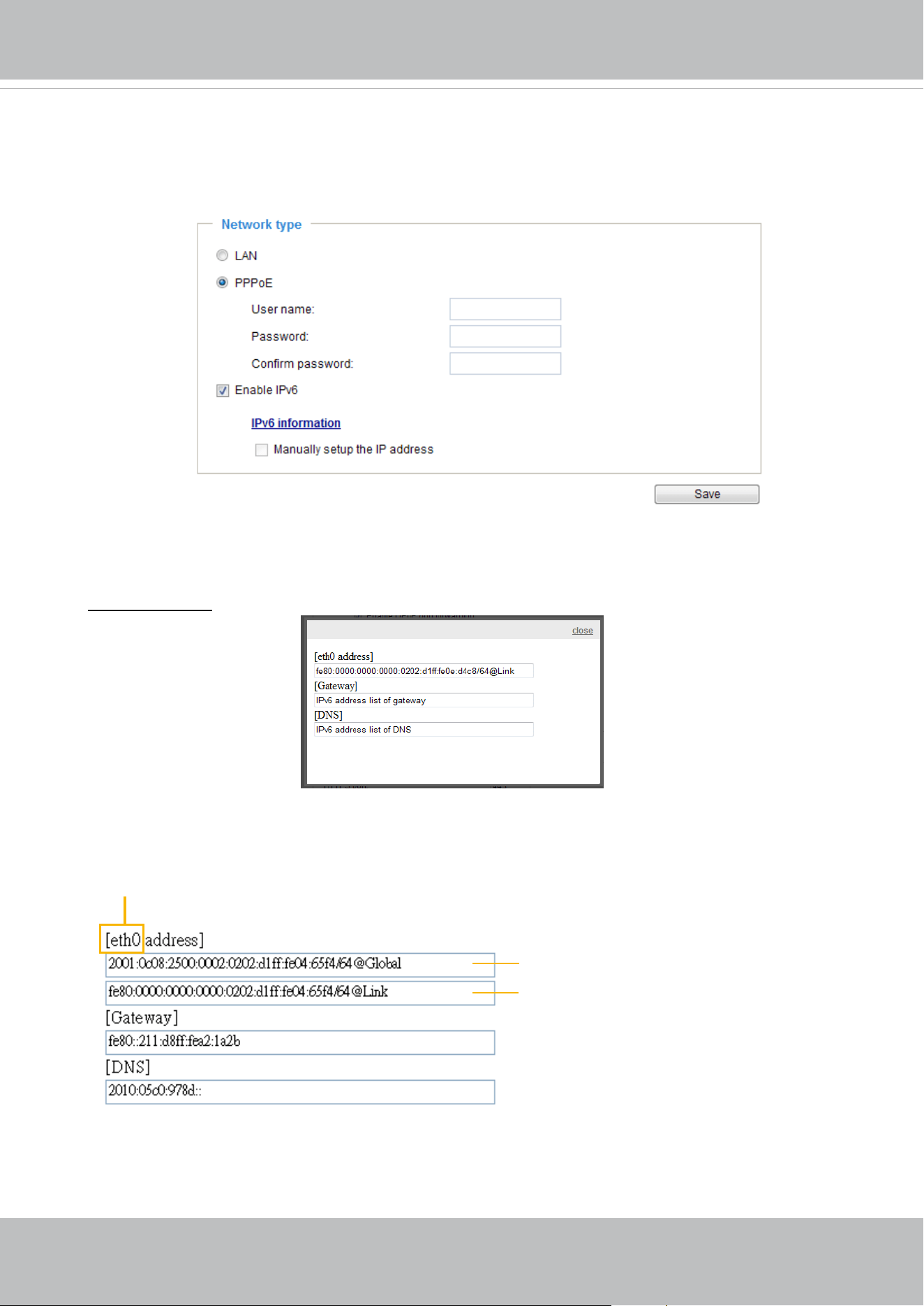
VIVOTEK
User's Manual - 101
Enable IPv6
Select this option and click Save to enable IPv6 settings.
Please note that this only works if your network environment and hardware equipment support
IPv6. The browser should be Microsoft
®
Internet Explorer 6.5, Mozilla Firefox 3.0 or above.
When IPv6 is enabled, by default, the network camera will listen to router advertisements and be
assigned with a link-local IPv6 address accordingly.
IPv6 Information: Click this button to obtain the IPv6 information as shown below.
If your IPv6 settings are successful, the IPv6 address list will be listed in the pop-up window. The
IPv6 address will be displayed as follows:
Link-global IPv6 address/network mask
Link-local IPv6 address/network mask
Refers to Ethernet
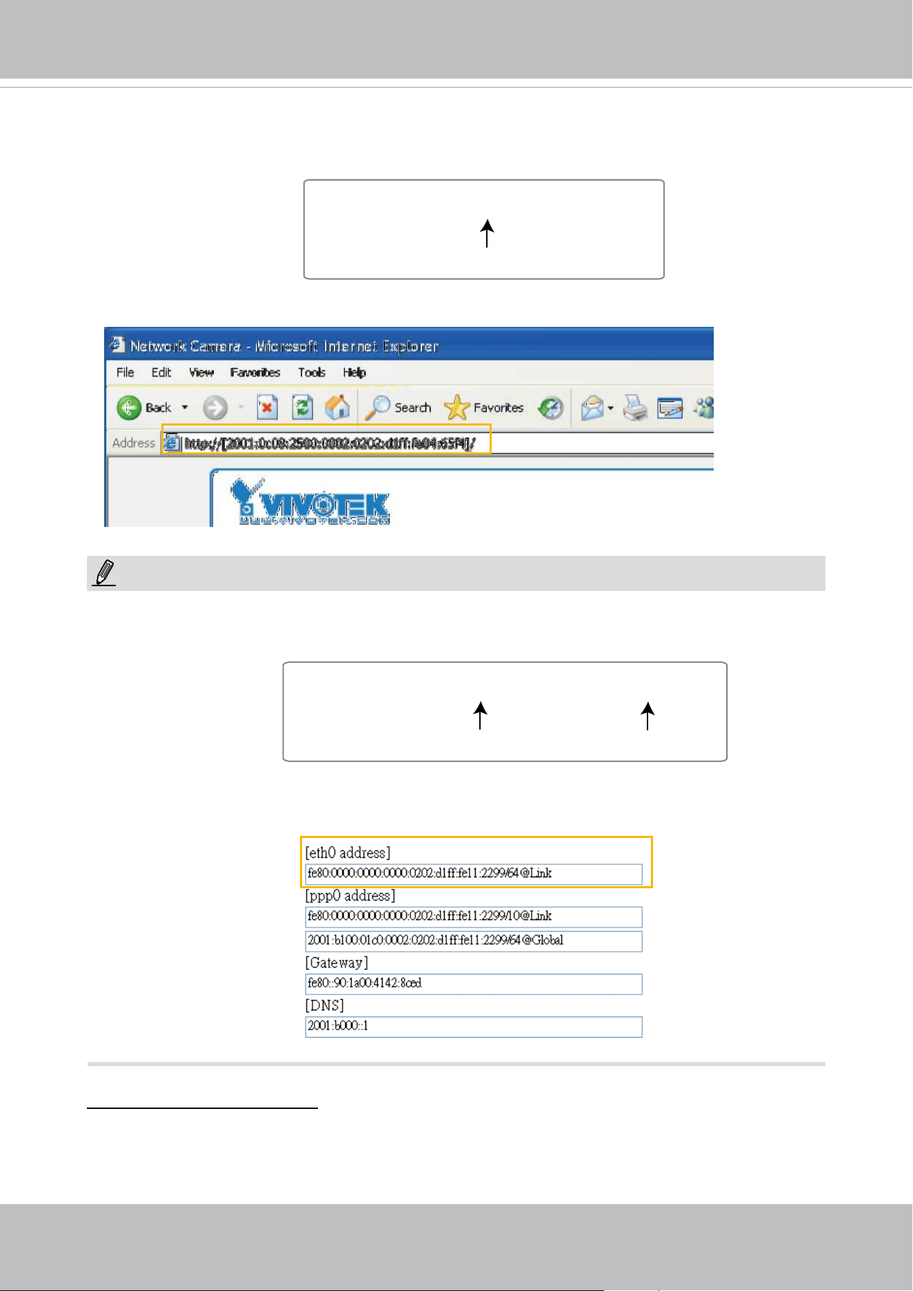
VIVOTEK
102 - User's Manual
Please follow the steps below to link to an IPv6 address:
1. Open your web browser.
2. Enter the link-global or link-local IPv6 address in the address bar of your web browser.
3. The format should be:
4. Press Enter on the keyboard or click Refresh button to refresh the webpage.
For example:
► If you have a Secondary HTTP port (the default value is 8080), you can also link to the webpage
using the following address format: (Please refer to HTTP streaming on page 104 for detailed
information.)
► If you choose PPPoE as the Network Type, the [
PPP0 address] will be displayed in the IPv6
information column as shown below.
Manually setup the IP address: Select this option to manually set up IPv6 settings if your network
environment does not have DHCPv6 server and router advertisements-enabled routers. If
you check this item, the following blanks will be displayed for you to enter the corresponding
information:
http://[2001:0c08:2500:0002:0202:d1ff:fe04:65f4]/
IPv6 address
http://[2001:0c08:2500:0002:0202:d1ff:fe04:65f4]/:8080
IPv6 address
Secondary HTTP port
NOTE:
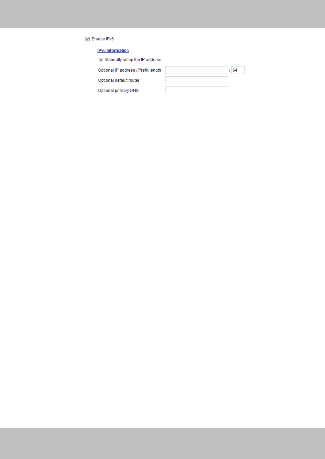
VIVOTEK
User's Manual - 103
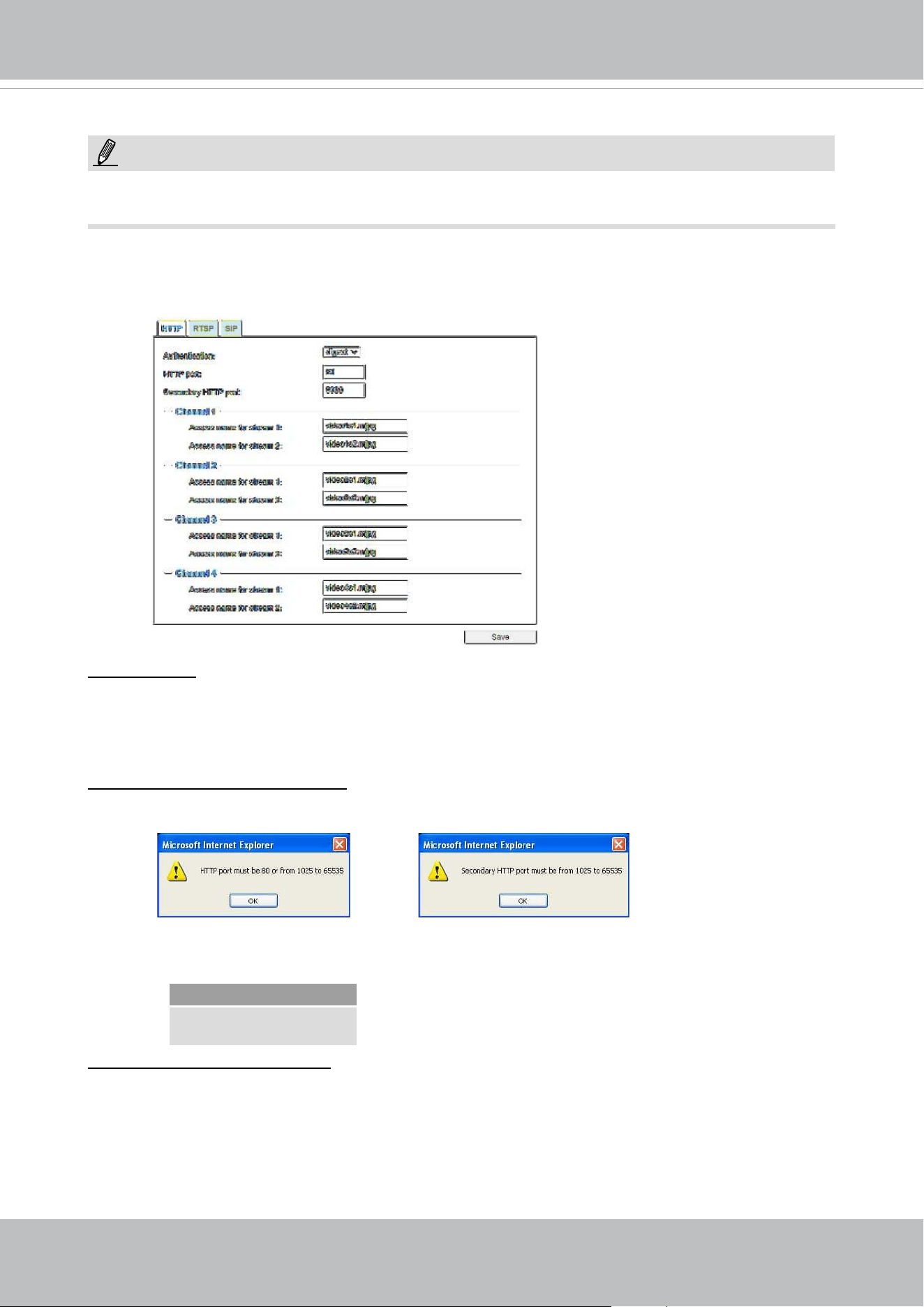
VIVOTEK
104 - User's Manual
Network > Streaming protocols
HTTP streaming
To utilize HTTP authentication, make sure that your have set a password for the Network Camera
rst; please refer to Security > User account on page 118 for details.
Authentication: Depending on your network security requirements, the Network Camera provides
two types of security settings for an HTTP transaction: basic and digest.
If
basic authentication is selected, the password is sent in plain text format and there can be
potential risks of being intercepted. If
digest authentication is selected, user credentials are
encrypted using MD5 algorithm and thus provide better protection against unauthorized accesses.
HTTP port / Secondary HTTP port: By default, the HTTP port is set to 80 and the secondary HTTP
port is set to 8080. They can also be assigned to another port number between 1025 and 65535. If
the ports are incorrectly assigned, the following warning messages will be displayed:
To access the Network Camera on the LAN, both the HTTP port and secondary HTTP port can
be used to access the Network Camera. For example, when the HTTP port is set to 80 and the
secondary HTTP port is set to 8080, refer to the list below for the Network Camera’s IP address.
Access name for stream 1 or 2: This Network camera supports multiple streams simultaneously.
The access name is used to identify different video streams. Users can click Media > Video >
Stream settings to congure the video quality of linked streams. For more information about how
to congure the video quality, please refer to Stream settings on page 83.
When using Mozilla Firefox to access the Network Camera and the video mode is set to JPEG,
users will receive video comprised of continuous JPEG images. This technology, known as “server
push”, allows the Network Camera to feed live pictures to Mozilla Firefox.
On the LAN
http://192.168.4.160 or
http://192.168.4.160:8080
NOTE:
The metadata information can only be transmitted through the HTTP main port. Metadata is not
available through the secondary HTTP port.
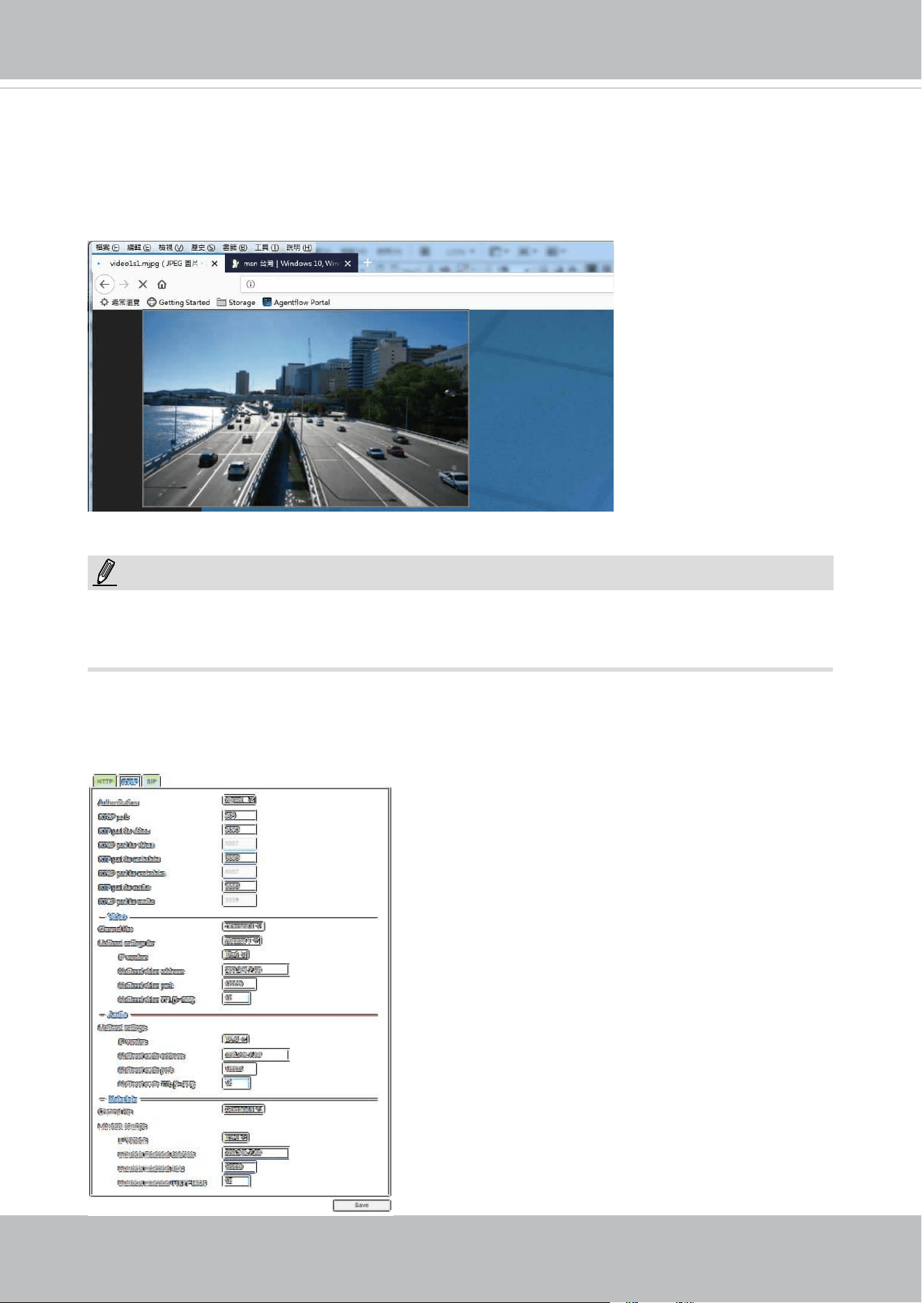
VIVOTEK
User's Manual - 105
URL command -- http://<ip address>:<http port>/<access name for stream 1 or 2>
For example, when the Access name for Channel 1 stream 2 is set to video1s2.mjpg:
1. Launch Mozilla Firefox or Netscape.
2. Type the above URL command in the address bar. Press Enter.
3. The JPEG images will be displayed in your web browser.
NOTE
► Microsoft
®
Internet Explorer does not support server push technology; therefore, you will not be
able to access a video stream using
http://<ip address>:<http port>/<access name for stream 1,
or 2>
.
RTSP Streaming
To utilize RTSP streaming authentication, make sure that you have set a password for controlling
the access to video stream rst. Please refer to Security > User account on page 118 for details.
NOTE:
http://192.168.5.151/video1s2.mjpg
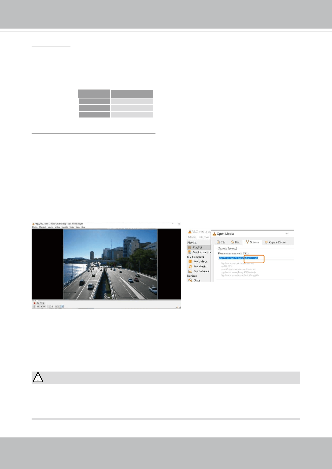
VIVOTEK
106 - User's Manual
IMPORTANT:
The Multicast metadata port is utilized by VIVOTEK VADP modules to transfer video analytics
results, PTZ stream, textual data, and event messages between the camera and the client side
running and observing the video analysis. If your client side computer is located outside the local
network, you may need to open the associated TCP port on routers and rewall.
Authentication: Depending on your network security requirements, the Network Camera provides
three types of security settings for streaming via RTSP protocol: disable, basic, and digest.
If
basic authentication is selected, the password is sent in plain text format, but there can be
potential risks of it being intercepted. If
digest authentication is selected, user credentials are
encrypted using MD5 algorithm, thus providing better protection against unauthorized access.
The availability of the RTSP streaming for the three authentication modes is listed in the following
table:
Access name for Channel # and stream #: This Network camera supports multiple streams
simultaneously. The access name is used to dierentiate the streaming source.
If you want to use an
RTSP player to access the Network Camera, you HAVE TO set the video
mode to
H.265 or 264 and use the following RTSP URL command to request transmission of the
streaming data.
rtsp://<ip address>:<rtsp port>/<access name for stream1 ~ 4>
For example, when the access name for stream 1 is set to live1s1.sdp:
1. Launch an RTSP player.
2. Choose File > Open URL. A URL dialog box will pop up.
3. Type the above URL command in the address eld.
4. The live video will be displayed in your player as shown
below.
VLC
Disable O
Basic O
Digest X
rtsp://192.168.5.151:554/live1s1.sdp
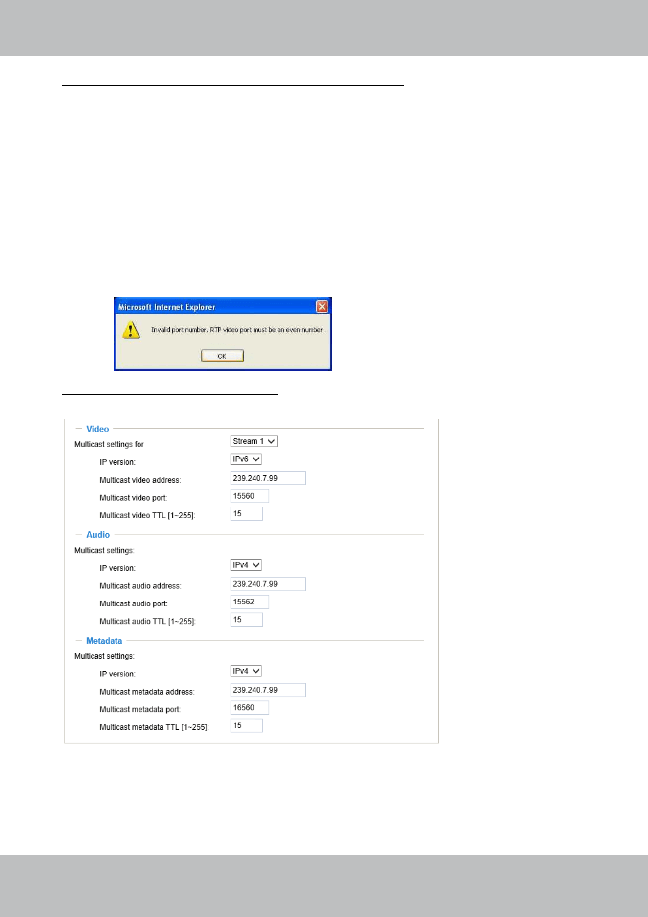
VIVOTEK
User's Manual - 107
RTSP port /RTP port for video, audio/ RTCP port for video, audio
■ RTSP (Real-Time Streaming Protocol) controls the delivery of streaming media. By default, the
port number is set to 554.
■ The RTP (Real-time Transport Protocol) is used to deliver video and audio data to the clients. By
default, the RTP port for video is set to 5556 and the RTP port for audio is set to 5558.
■ The RTCP (Real-time Transport Control Protocol) allows the Network Camera to transmit the
data by monitoring the Internet trac volume. By default, the RTCP port for video is set to 5557
and the RTCP port for audio is set to 5559.
The ports can be changed to values between 1025 and 65535. The RTP port must be an even
number and the RTCP port is the RTP port number plus one, and thus is always an odd number.
When the RTP port changes, the RTCP port will change accordingly.
If the RTP ports are incorrectly assigned, the following warning message will be displayed:
Multicast settings for stream #1 ~ #3: Click the items to display the detailed configuration
information. Select the Always multicast option to enable multicast for streams #1 ~ #3.
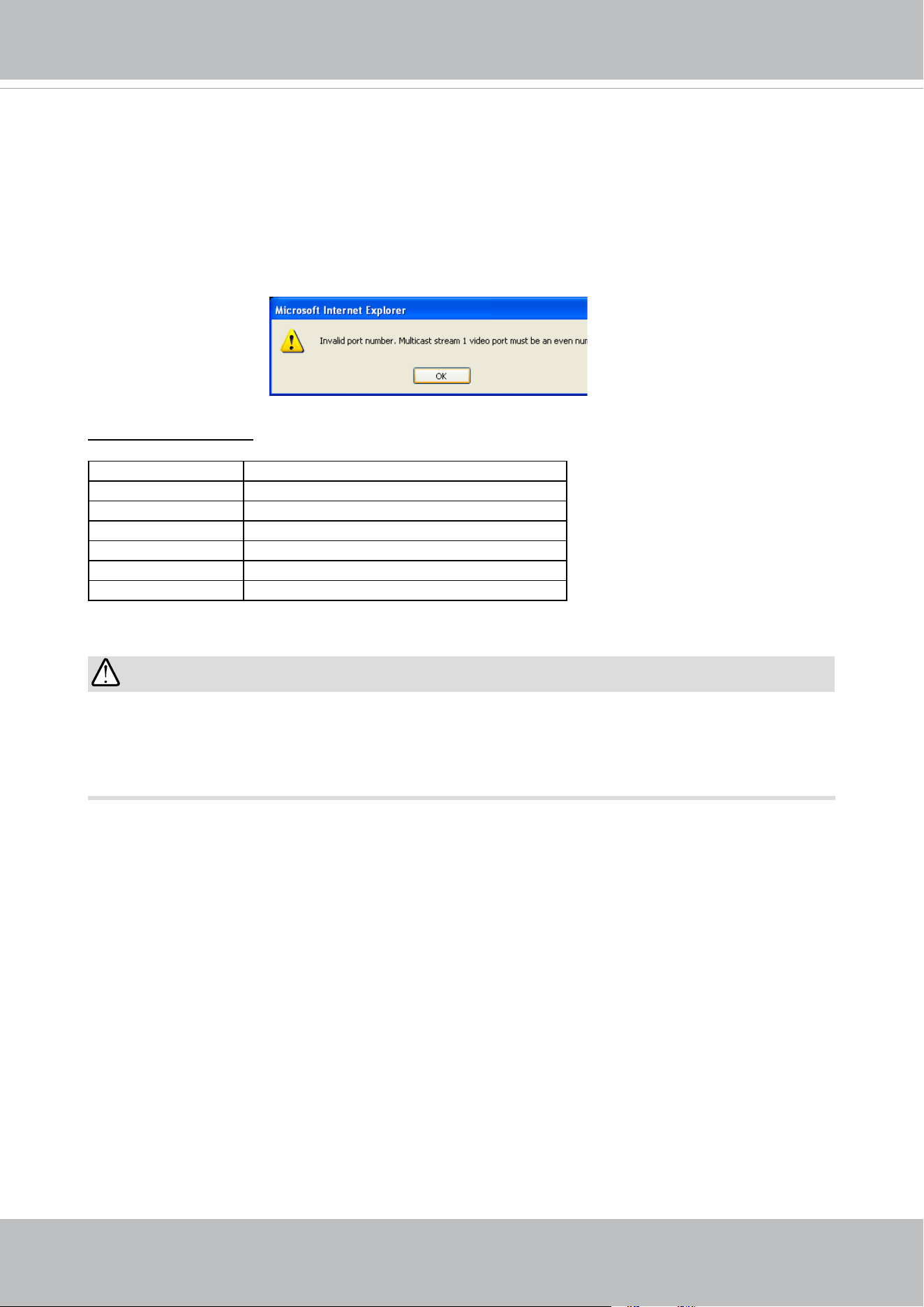
VIVOTEK
108 - User's Manual
Unicast video transmission delivers a stream through point-to-point transmission; multicast, on the
other hand, sends a stream to the multicast group address and allows multiple clients to acquire
the stream at the same time by requesting a copy from the multicast group address. Therefore,
enabling multicast can eectively save Internet bandwith.
The ports can be changed to values between 1025 and 65535. The multicast RTP port must be an
even number and the multicast RTCP port number is the multicast RTP port number plus one, and
thus is always odd. When the multicast RTP port changes, the multicast RTCP port will change
accordingly.
If the multicast RTP video ports are incorrectly assigned, the following warning message will be
displayed:
Multicast TTL [1~255]: The multicast TTL (Time To Live) is the value that tells the router the range
a packet can be forwarded. Each hop decreases TTL by one.
Initial TTL Scope
0 Restricted to the same host
1 Restricted to the same subnetwork
15 Restricted to the same site
64 Restricted to the same region
128 Restricted to the same continent
255 Unrestricted in scope
IMPORTANT:
The Multicast metadata port is utilized by VIVOTEK VADP modules to transfer video analytics
results, PTZ stream, textual data, and event messages between the camera and the client side
running and observing the video analysis. If your client side computer is located outside the local
network, you may need to open the associated TCP port on routers and rewall.
VIVOTEK
User's Manual - 109
SIP
SIP is short for Session Initiation Protocol. If necessary, you can change the default port number,
5060, to one between 1025 and 65535.
Two way audio port: By default, the two way audio port is set to 5060. Also, it can also be assigned
to another port number between 1025 and 65535.
The Network Camera supports two way audio communication so that operators can transmit and
receive audio simultaneously. By using the Network Camera’s built-in or external microphone and
an external speaker, you can communicate with people around the Network Camera.
Note that as JPEG only transmits a series of JPEG images to the client, to enable the two-way
audio function, make sure the video mode is set to "H.264" on the Media > Video > Stream settings
page and the media option is set to “Media > Video > Stream settings” on the Client Settings page.
Please refer to Client Settings on page 50 and Stream settings on page 86.
Audio transmitted from operators
Audio transmitted to operators
America
Taiwan
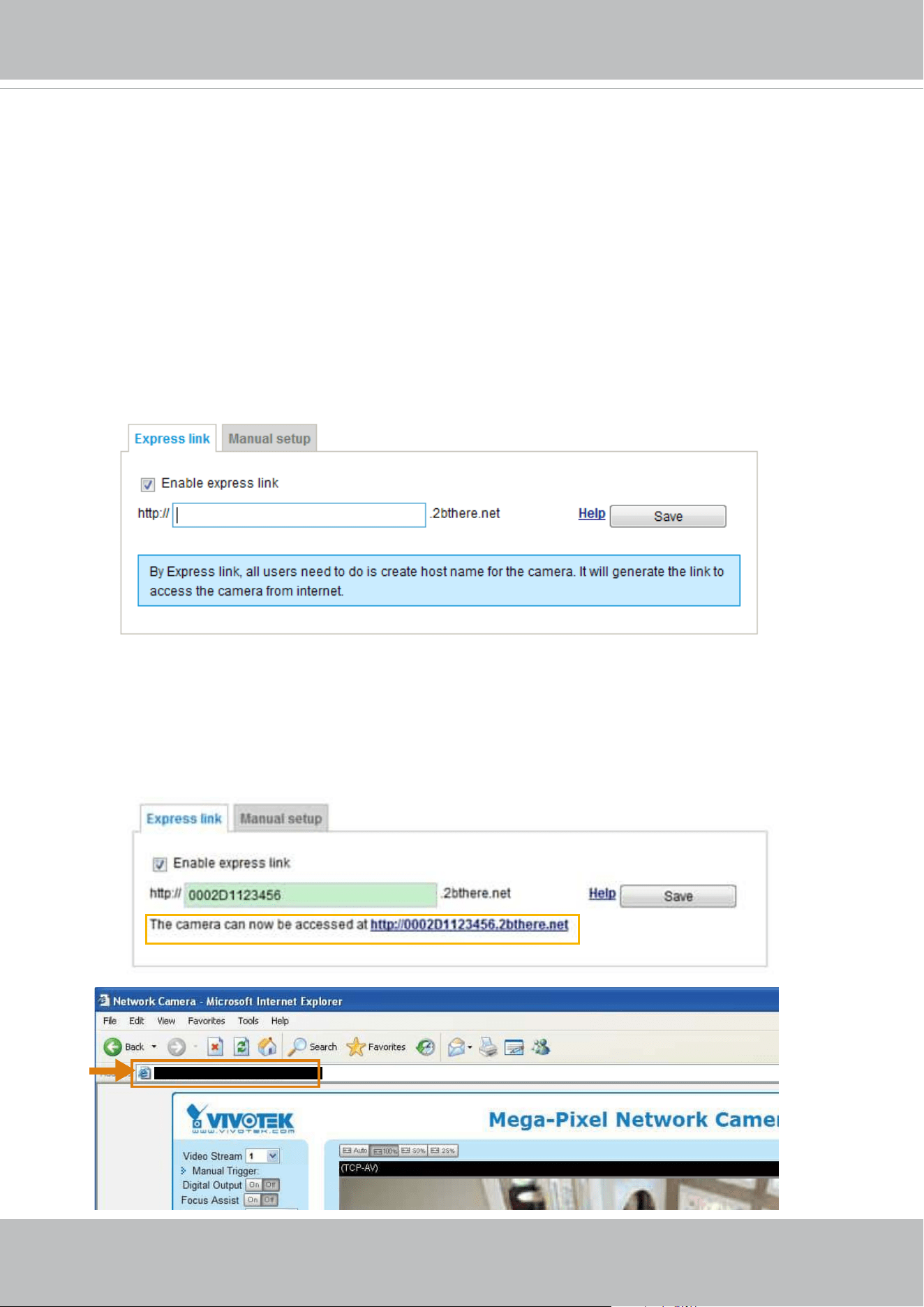
VIVOTEK
110 - User's Manual
Network > DDNS
This section explains how to congure the dynamic domain name service for the Network
Camera. DDNS is a service that allows your Network Camera, especially when assigned
with a dynamic IP address, to have a xed host and domain name.
Express link
Express Link is a free service provided by VIVOTEK server, which allows users to register
a domain name for a network device. One URL can only be mapped to one MAC address.
This service will examine if the host name is valid and automatically open a port on your
router. If using DDNS, the user has to manually congure UPnP port forwarding. Express
Link is more convenient and easier to set up.
Please follow the steps below to enable Express Link:
1. Make sure that your router supports UPnP port forwarding and it is activated.
2. Check Enable express link.
3. Enter a host name for the network device and click Save. If the host name has been used by
another device, a warning message will show up. If the host name is valid, it will display a
message as shown below.
https://0002D1123456.2bthere.net
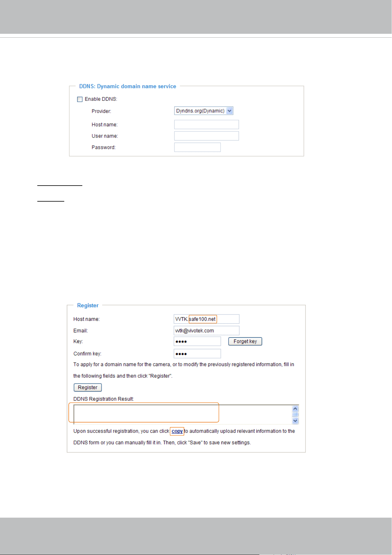
VIVOTEK
User's Manual - 111
Manual setup
DDNS: Dynamic domain name service
Enable DDNS: Select this option to enable the DDNS setting.
Provider: Select a DDNS provider from the provider drop-down list.
VIVOTEK offers
Safe100.net, a free dynamic domain name service, to VIVOTEK customers. It
is recommended that you register
Safe100.net to access VIVOTEK’s Network Cameras from the
Internet. Additionally, we offer other DDNS providers, such as Dyndns.org(Dynamic), Dyndns.
org(Custom), TZO.com, DHS.org, CustomSafe100, dyn-interfree.it.
Note that before utilizing this function, please apply for a dynamic domain account rst.
■
Safe100.net
1. In the DDNS column, select Safe100.net from the drop-down list. Click I accept after reviewing
the terms of the Service Agreement.
2. In the Register column, ll in the Host name (xxxx.safe100.net), Email, Key, and Conrm Key,
and click Register. After a host name has been successfully created, a success message will
be displayed in the DDNS Registration Result column.
3. Click Copy and all the registered information will automatically be uploaded to the corresponding
elds in the DDNS column at the top of the page as seen in the picture.
[Register] Successfully Your account information has
been mailed to registered e-mail address
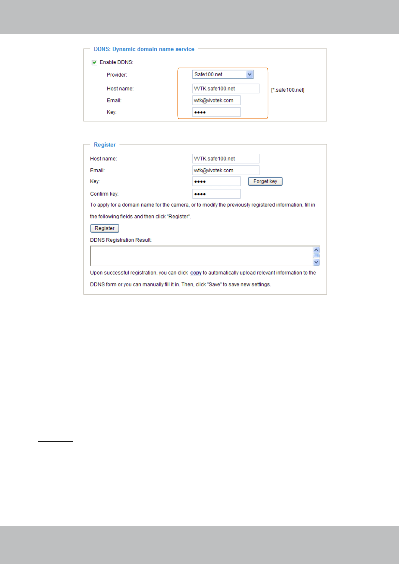
VIVOTEK
112 - User's Manual
[Register] Successfully Your account information has
been mailed to registered e-mail address
4. Select Enable DDNS and click Save to enable the setting.
■
CustomSafe100
VIVOTEK offers documents to establish a CustomSafe100 DDNS server for distributors and
system integrators. You can use CustomSafe100 to register a dynamic domain name if your
distributor or system integrators oer such services.
1. In the DDNS column, select CustomSafe100 from the drop-down list.
2. In the Register column, ll in the Host name, Email, Key, and Conrm Key; then click Register.
After a host name has been successfully created, you will see a success message in the DDNS
Registration Result column.
3. Click Copy and all for the registered information will be uploaded to the corresponding elds in
the DDNS column.
4. Select Enable DDNS and click Save to enable the setting.
Forget key: Click this button if you have forgotten the key to Safe100.net or CustomSafe100. Your
account information will be sent to your email address.
Refer to the following links to apply for a dynamic domain account when selecting other
DDNS providers:
■
Dyndns.org(Dynamic) / Dyndns.org(Custom): visit http://www.dyndns.com/
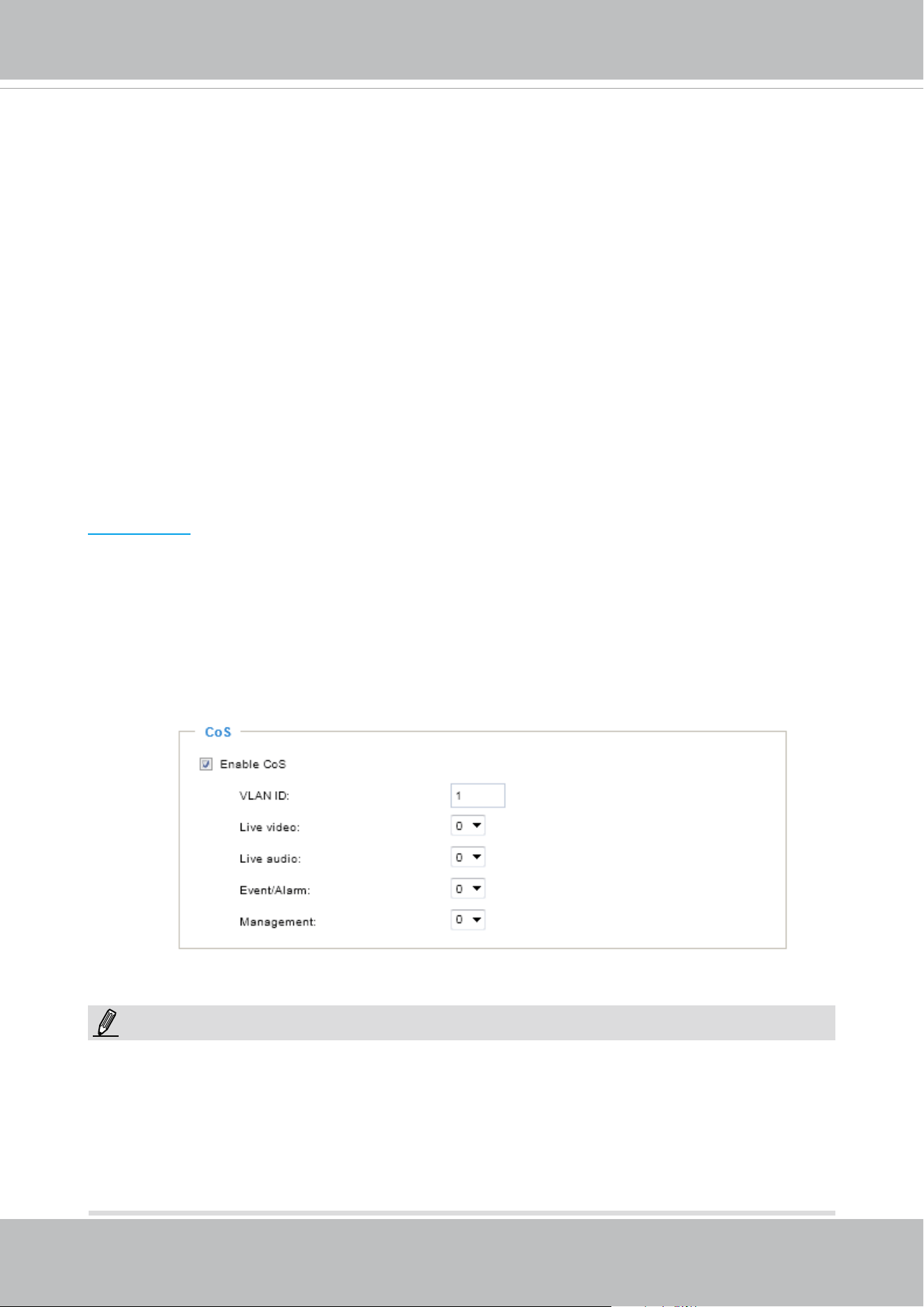
VIVOTEK
User's Manual - 113
Network > QoS (Quality of Service)
Quality of Service refers to a resource reservation control mechanism, which guarantees a certain
quality to different services on the network. Quality of service guarantees are important if the
network capacity is insucient, especially for real-time streaming multimedia applications. Quality
can be dened as, for instance, a maintained level of bit rate, low latency, no packet dropping, etc.
The following are the main benets of a QoS-aware network:
■
The ability to prioritize trac and guarantee a certain level of performance to the data ow.
■
The ability to control the amount of bandwidth each application may use, and thus provide higher
reliability and stability on the network.
Requirements for QoS
To utilize QoS in a network environment, the following requirements must be met:
■
All network switches and routers in the network must include support for QoS.
■
The network video devices used in the network must be QoS-enabled.
QoS models
CoS (the VLAN 802.1p model)
IEEE802.1p denes a QoS model at OSI Layer 2 (Data Link Layer), which is called CoS, Class of
Service. It adds a 3-bit value to the VLAN MAC header, which indicates the frame priority level from
0 (lowest) to 7 (highest). The priority is set up on the network switches, which then use dierent
queuing disciplines to forward the packets.
Below is the setting column for CoS. Enter the VLAN ID of your switch (0~4095) and choose the
priority for each application (0~7).
If you assign Video the highest level, the switch will handle video packets rst.
NOTE:
► A VLAN Switch (802.1p) is required. Web browsing may fail if the CoS setting is incorrect.
►The Class of Service technologies do not guarantee a level of service in terms of bandwidth
and delivery time; they oer a "best-eort." Users can think of CoS as "coarsely-grained" trac
control and QoS as "nely-grained" trac control.
► Although CoS is simple to manage, it lacks scalability and does not oer end-to-end guarantees
since it is based on L2 protocol.
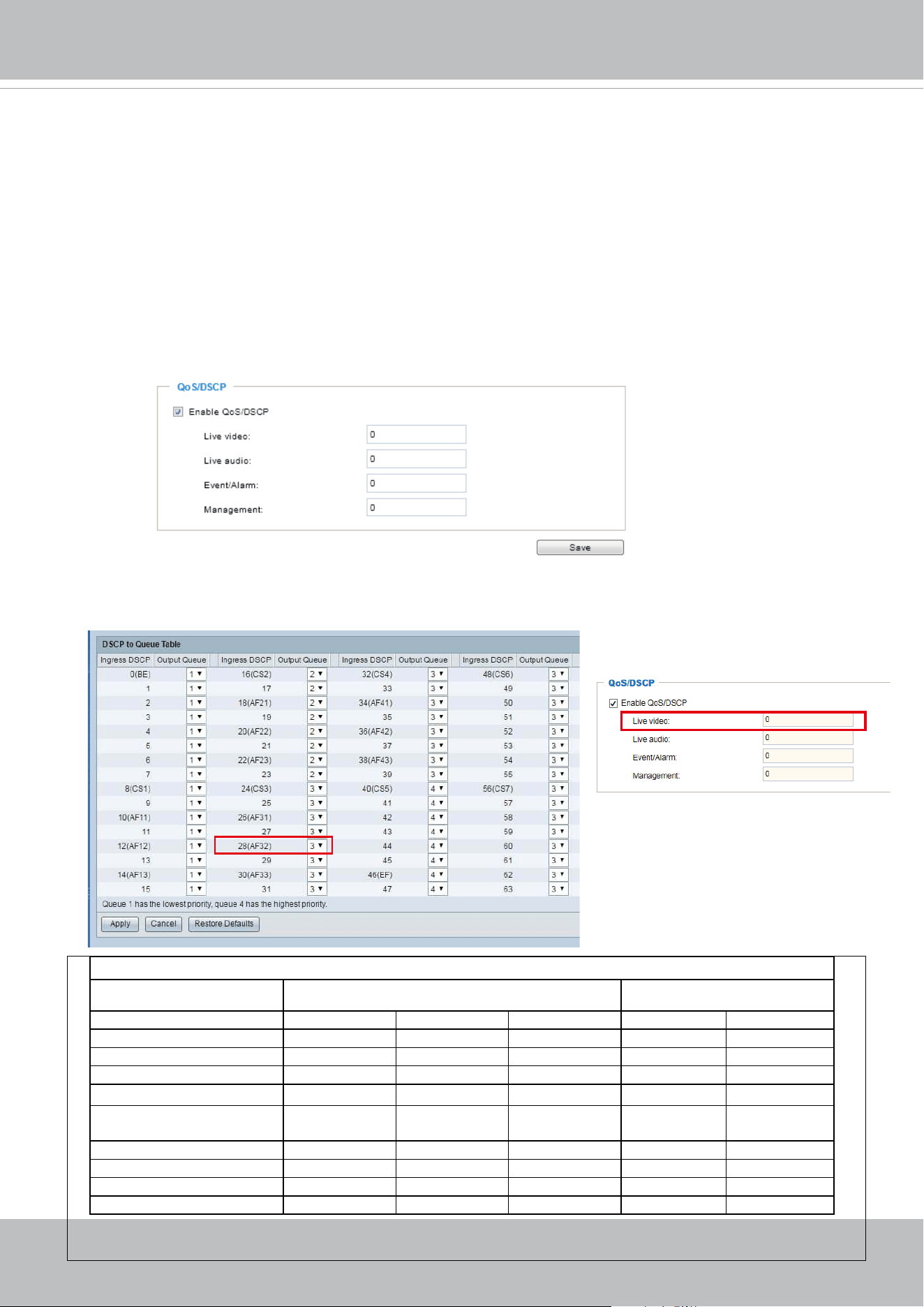
VIVOTEK
114 - User's Manual
QoS/DSCP (the DiServ model)
DSCP-ECN denes QoS at Layer 3 (Network Layer). The Dierentiated Services (DiServ) model
is based on packet marking and router queuing disciplines. The marking is done by adding a eld
to the IP header, called the DSCP (Differentiated Services Codepoint). This is a 6-bit field that
provides 64 different class IDs. It gives an indication of how a given packet is to be forwarded,
known as the Per Hop Behavior (PHB). The PHB describes a particular service level in terms of
bandwidth, queueing theory, and dropping (discarding the packet) decisions. Routers at each
network node classify packets according to their DSCP value and give them a particular forwarding
treatment; for example, how much bandwidth to reserve for it.
Below are the setting options of DSCP (DiffServ Codepoint). Specify the DSCP value for each
application (0~63).
Note that different vendors of network devices might have different methodologies and unique
implementations. Shown below is a sample corresponding information from a Cisco switch. You
should enter a DSCP tag value according to the information provided by the network devices.
32
QoS Baseline/Technical Marketing Classication and Marking Recommendations
Application Layer3 Classication Layer 2 CoS/MPLS EXP
IPP PHB DSCP
IP Routing 6 CS6 48 6
Voice 5 EF 46 5
Interactive Video 4 AF41 34 4 QoS B
Streaming-Video 4 CS4 32 4
Locally-dened Mission-
Critical Data
3 - 25 3
Call-signaling 3 AF31/CS3 26/24 3
Transactional Data 2 AF21 18 2
Network Management 2 CS2 16 2
Bulk Data 1 AF11 10 1
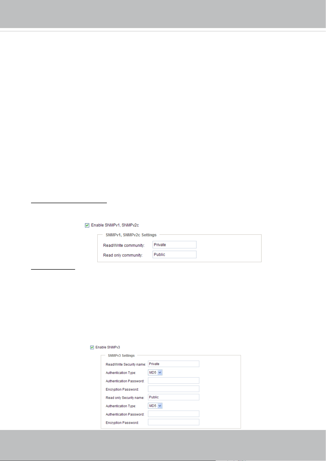
VIVOTEK
User's Manual - 115
Network > SNMP
(Simple Network Management Protocol)
This section explains how to use the SNMP on the network camera. The Simple Network
Management Protocol is an application layer protocol that facilitates the exchange of
management information between network devices. It helps network administrators to
remotely manage network devices and nd, solve network problems with ease.
■ The SNMP consists of the following three key components:
1. Manager: Network-management station (NMS), a server which executes applications that
monitor and control managed devices.
2. Agent: A network-management software module on a managed device which transfers the status
of managed devices to the NMS.
3. Managed device: A network node on a managed network. For example: routers, switches,
bridges, hubs, computer hosts, printers, IP telephones, network cameras, web server, and
database.
Before conguring SNMP settings on the this page, please enable your NMS rst.
SNMP Conguration
Enable SNMPv1, SNMPv2c
Select this option and enter the names of Read/Write community and Read Only community
according to your NMS settings.
Enable SNMPv3
This option contains cryptographic security, a higher security level, which allows you to set the
Authentication password and the Encryption password.
■ Security name: According to your NMS settings, choose Read/Write or Read Only and enter the
community name.
■ Authentication type: Select MD5 or SHA as the authentication method.
■ Authentication password: Enter the password for authentication (at least 8 characters).
■ Encryption password: Enter a password for encryption (at least 8 characters).
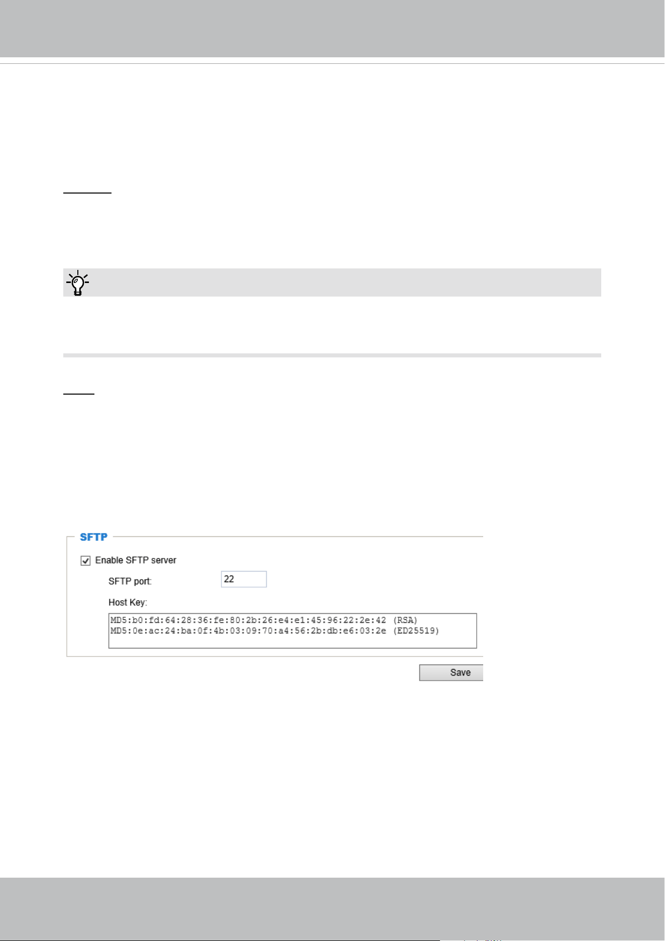
VIVOTEK
116 - User's Manual
You can FTP the camera’s IP address to download videos recorded in the SD card, or use the “http://
ip/cgi-bin/admin/lsctrl.cgi?cmd=search
” command to examine the recorded les on your SD card.
Tips:
Network > FTP
The newer rmware disabled the FTP port for security concerns. You can manually enable the FTP
server service to enable the FTP function. You can disable the FTP server function when it is not in
use.
FTP port: The FTP server allows the user to save recorded video clips. You can utilize VIVOTEK's
Shepherd utility to upgrade the rmware via FTP server. By default, the FTP port is set to 21. It can
also be assigned to another port number between 1025 and 65535.
SFTP:
This is the embedded SFTP client. Host Key: A host key is the SFTP server's public key.
Ensuring the SFTP server is validated is an important aspect of the SFTP protocol. It is
designed to protect against man-in-the-middle attacks where the hacker intercepts and
relays an impersonated message to the other party.
Click the Save button and the camera SFTP server MD5 key will display. The default
format is ED25519 and RSA.
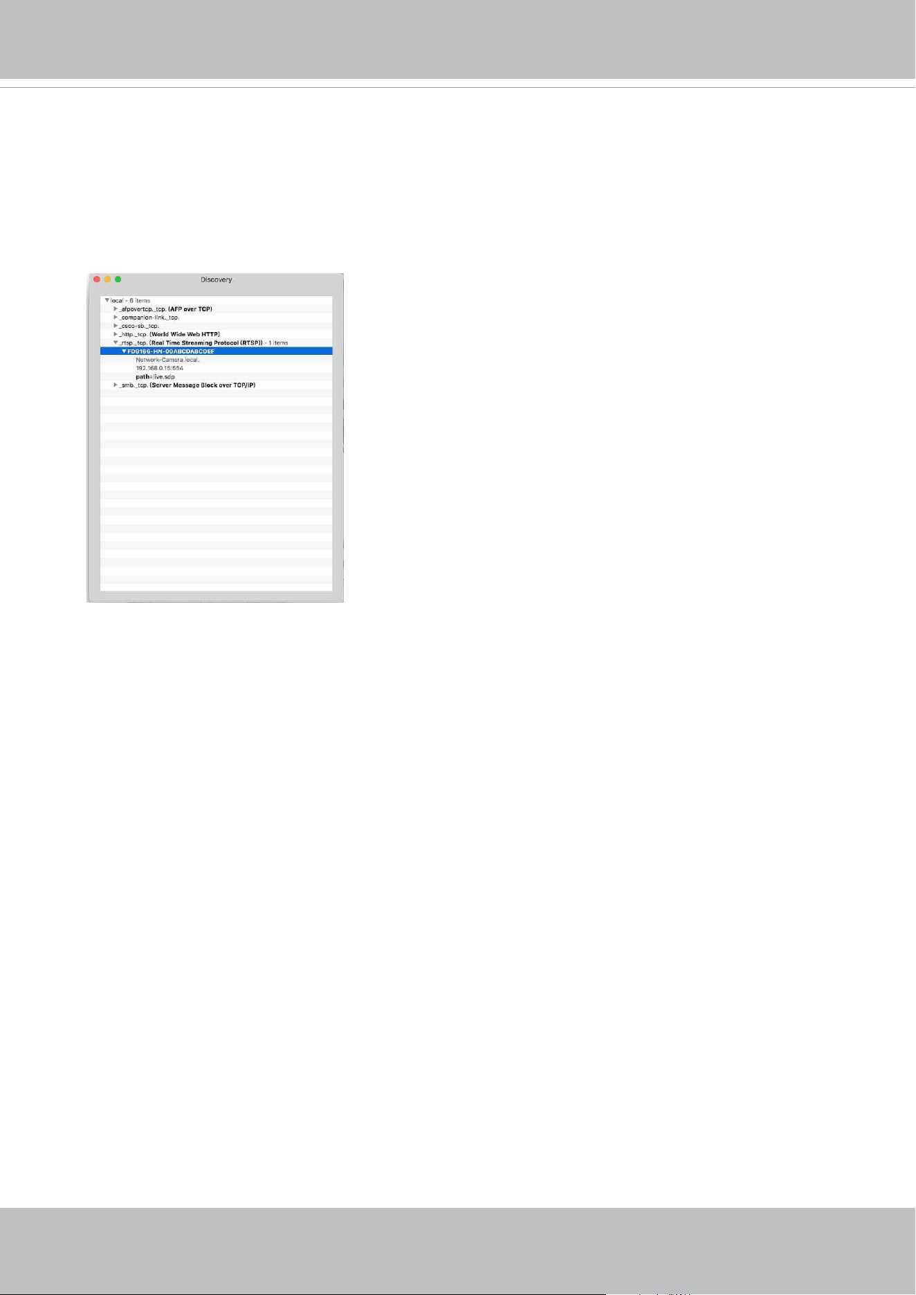
VIVOTEK
User's Manual - 117
Bonjour
To access the camera from a Mac computer, go to Safari, click on Bonjour and select the camera
from a drop-down list.
You can go to Safari > Preferences to enter your user name and password, and provide the root
password the rst time you access the camera. The camera main page will open in your browser.
Some later iOSes may come without the Bonjour option. Install the Discovery utility instead.
Find the Discovery (formerly Bonjour Browser) from the Mac App Store.
Discovery is a utility that displays all the Bonjour services on your local network or on Wide-Area
Bonjour domains. The utility is previously called Bonjour Browser, it is now distributed on the Mac
App Store.
Discovery requires macOS 10.12 or higher. For older versions of Mac OS you can download the
old version of Bonjour Browser.
Bonjour Browser (obsolete)
http://www.tildesoft.com/les/BonjourBrowser.dmg - Version 1.5.6
Discovery for iOS
https://itunes.apple.com/us/app/discovery-dns-sd-browser/id305441017?mt=8
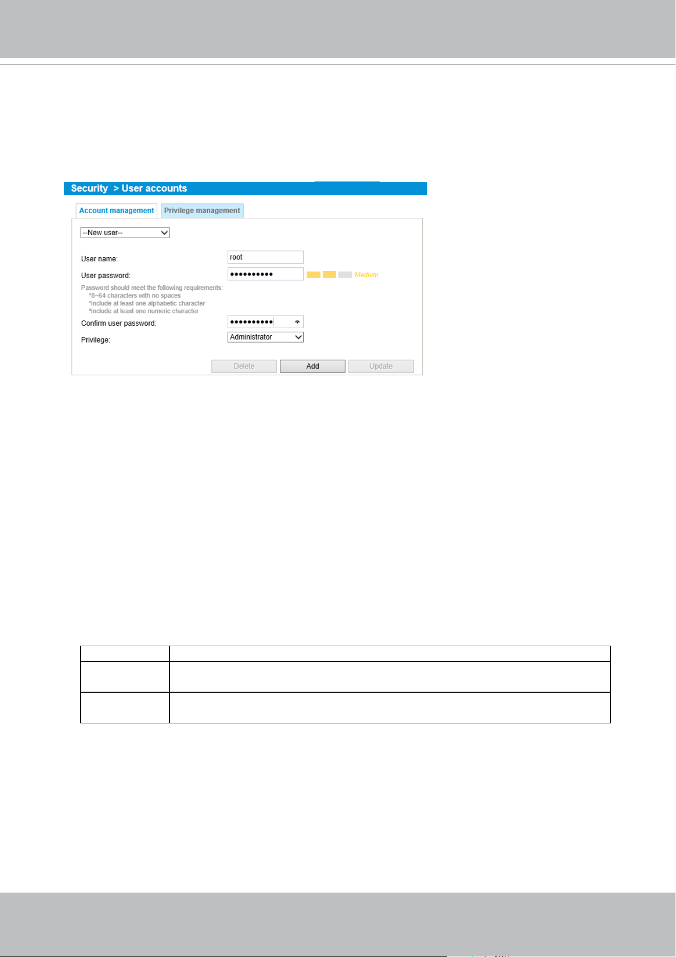
VIVOTEK
118 - User's Manual
Security > User accounts
This section explains how to enable password protection and create multiple accounts.
Account management
The administrator account name is “root”, which is permanent and can not be deleted. If you want
to add more accounts in the Account management window, please apply the password for the “root”
account rst.
The administrator can create up to 20 user accounts.
To create a new user,
1. Click to unfold the pull-down menu. Select New user.
2. Enter the new user’s name and password. Type the password identically in both text boxes.
Some, but not all special ASCII characters are supported: !, $, %, -, ., @, ^, _, and ~.
You can use them in the password combination.
The strength of your password combination is shown on the right, use the combination of
alphabetic, numeric, upper case, and lower case characters until the password strength is good
enough.
3. Select the privilege level for the new user account. Click Add to enable the setting.
The privilege levels are listed below:
Administrator Full control
Operator Control DO, white-light illuminator, snapshot, and PTZ;
the operator is unable to enter the camera Conguration page.
Viewer Control DO, white-light illuminator, view, listen, PTZ, and talk through the
camera interface.
Access rights are sorted by user privilege (Administrator, Operator, and Viewer). Only
administrators can access the Configuration page. Although operators cannot access the
Configuration page, they can use the URL Commands to get and set the value of parameters.
Viewers can only access the main page for live viewing.
Here you can also change a user’s access rights or delete user accounts.
1. Select an existing account to modify.
2. Make necessary changes and click Update or Delete to enable the setting.
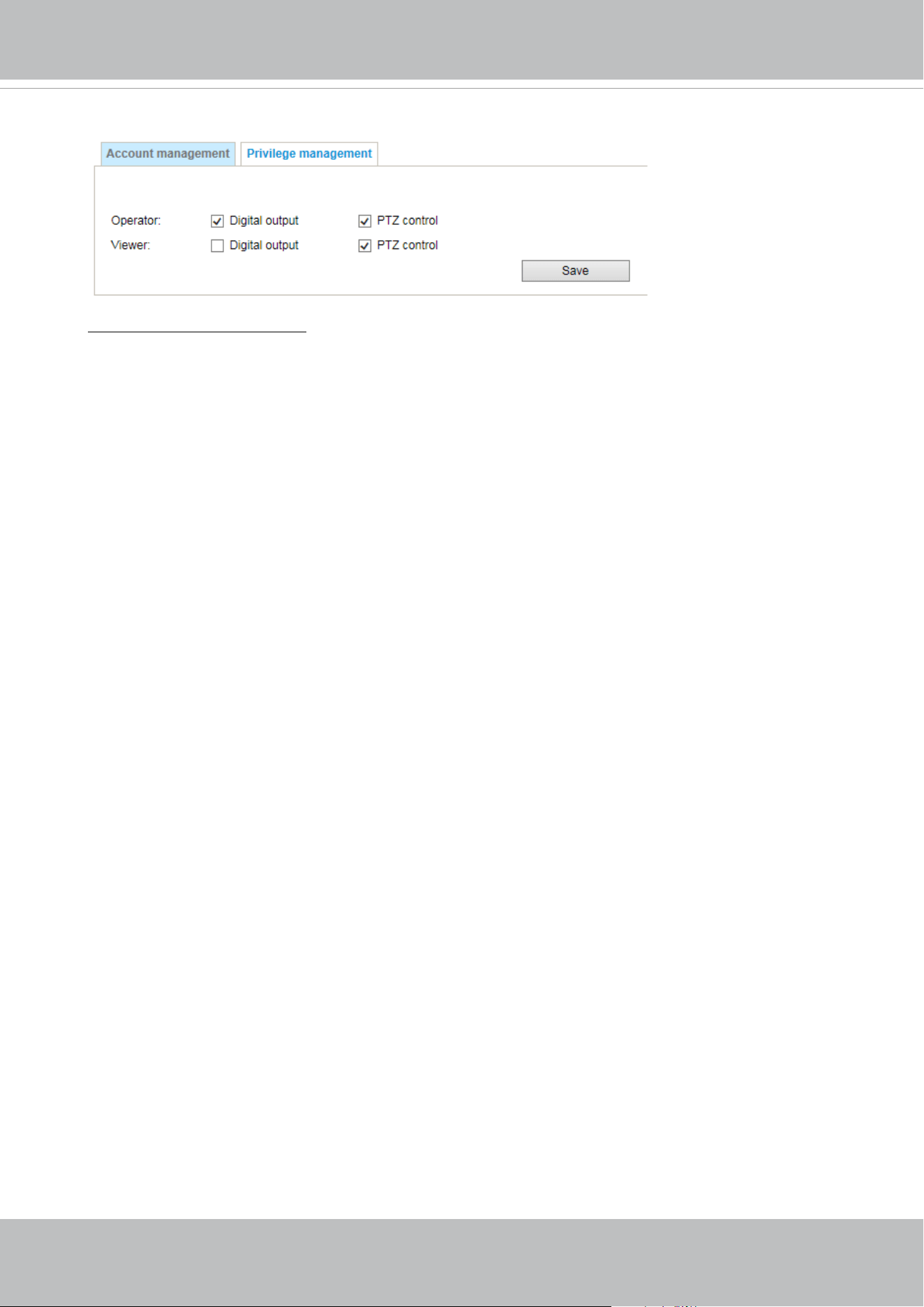
VIVOTEK
User's Manual - 119
Privilege management
Digital Output & PTZ control: You can modify the management privilege as operators or viewers.
Select or de-select the checkboxes, and then click Save to enable the settings. If you give Viewers
the privilege, Operators will also have the ability to control the Network Camera through the main
page.
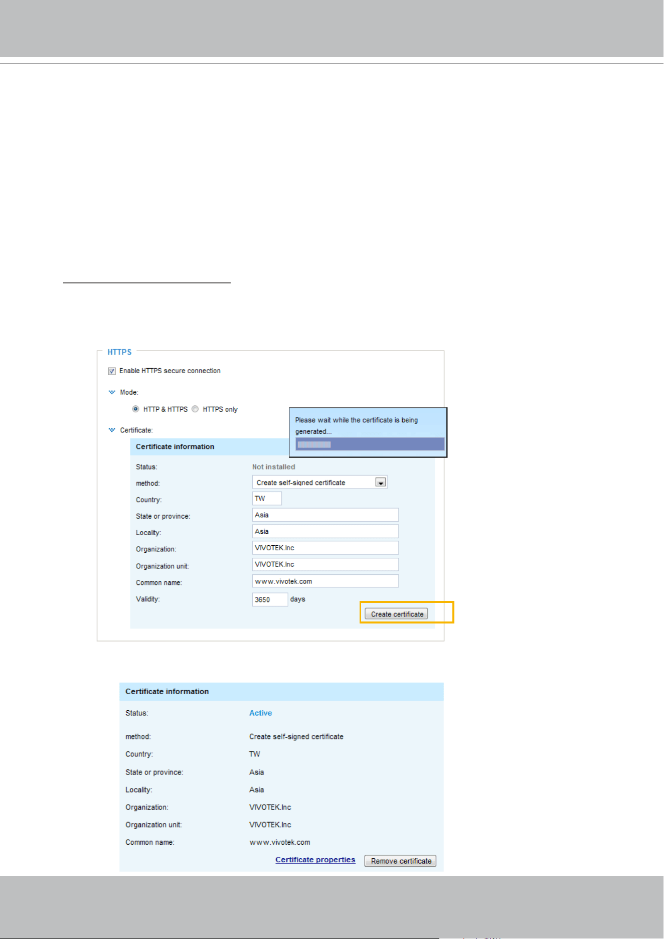
VIVOTEK
120 - User's Manual
Security > HTTPS
(Hypertext Transfer Protocol over SSL)
This section explains how to enable authentication and encrypted communication over
SSL (Secure Socket Layer). It helps protect streaming data transmission over the Internet
on higher security level.
Create and Install Certicate Method
Before using HTTPS for communication with the Network Camera, a Certicate must be created
rst. There are three ways to create and install a certicate:
Create self-signed certificate
1. Select this option from a pull-down menu.
2. In the rst column, select Enable HTTPS secure connection, then select a connection option:
“HTTP & HTTPS” or “HTTPS only”.
3. Click Create certicate to generate a certicate.
4. The Certicate Information will automatically be displayed as shown below. You can click Certi-
cate properties to view detailed information about the certicate.
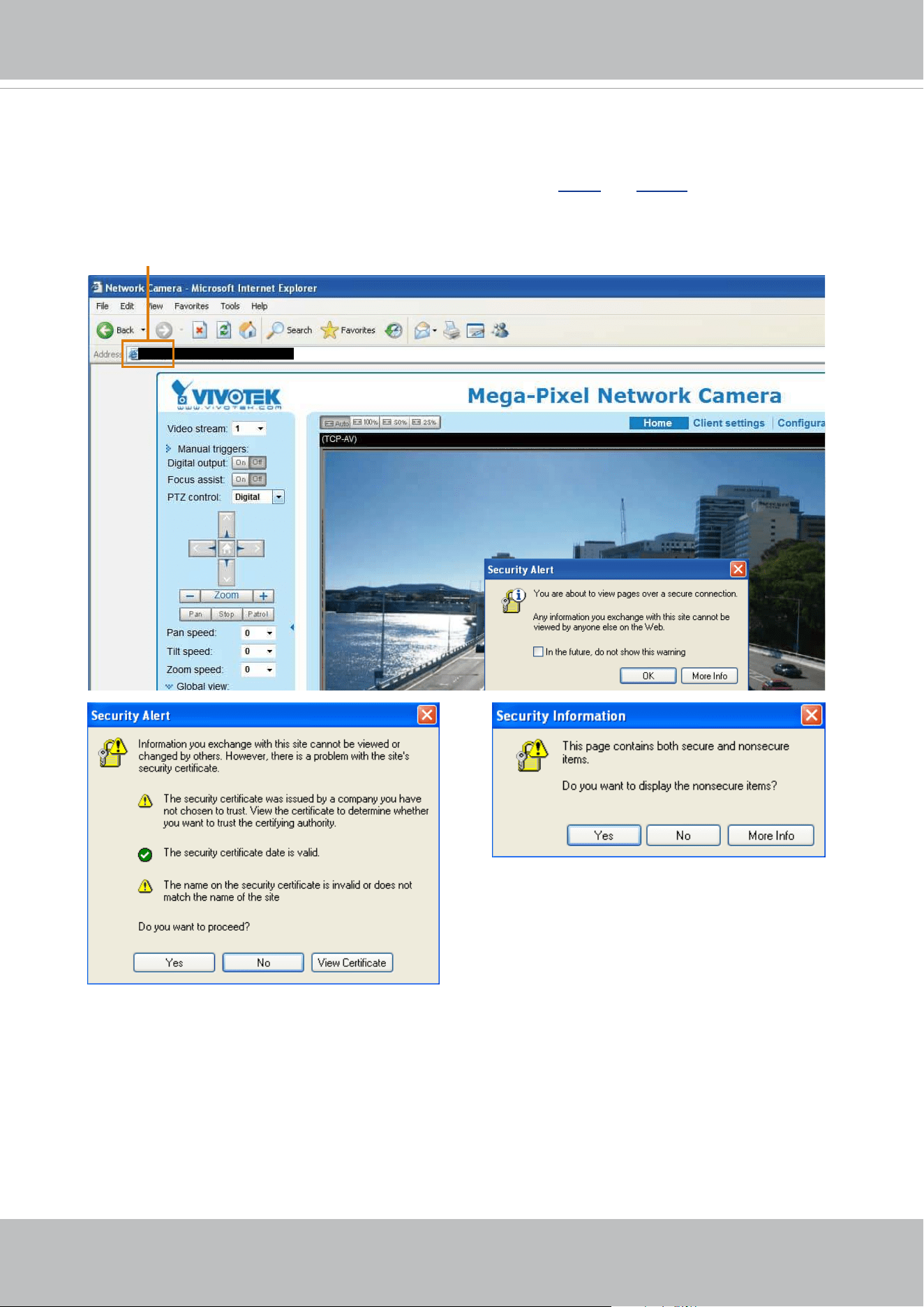
VIVOTEK
User's Manual - 121
5. Click Save to preserve your conguration, and your current session with the camera will change
to the encrypted connection.
6. If your web session does not automatically change to an encrypted HTTPS session, click Home
to return to the main page. Change the URL address from “
http://” to “https://“ in the address bar
and press Enter on your keyboard. Some Security Alert dialogs will pop up. Click OK or Yes to
enable HTTPS.
https://192.168.5.151/index.html
https://
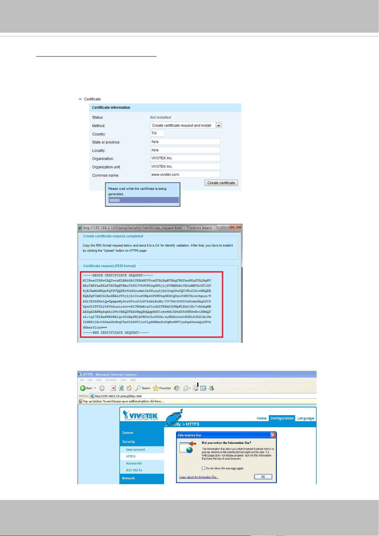
VIVOTEK
122 - User's Manual
Create certificate request and install
1. Select the option from the Method pull-down menu.
2. Click Create certicate to proceed.
3. The following information will show up in a pop-up window after clicking Create. Then click Save
to generate the certicate request.
4. The Certicate request window will prompt.
If you see the following Information bar, click OK and click on the Information bar at the top of
the page to allow pop-ups.
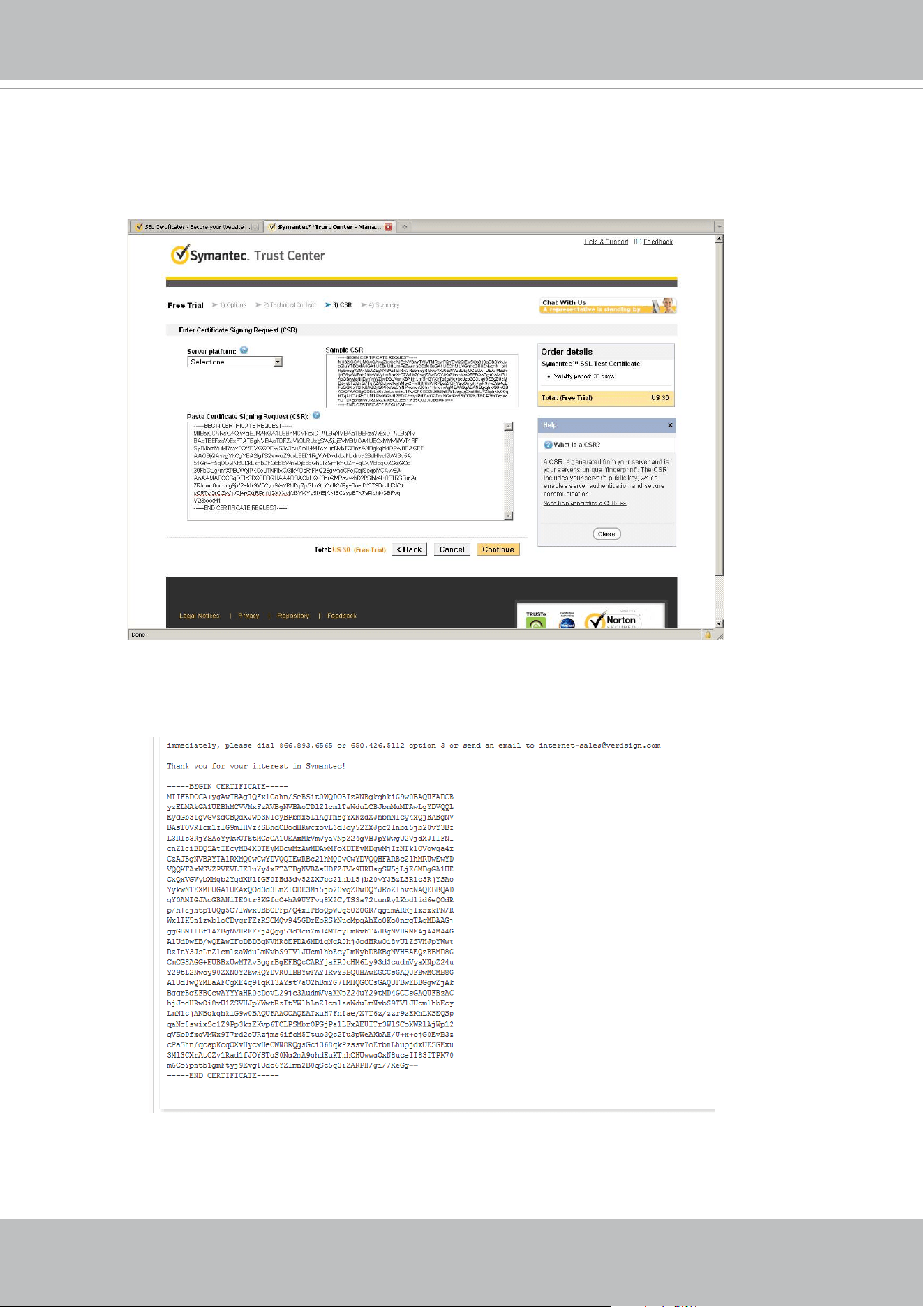
VIVOTEK
User's Manual - 123
5. Look for a trusted certicate authority, such as Symantec’s VeriSign Authentication Services, that
issues digital certicates. Sign in and purchase the SSL certication service. Copy the certicate
request from your request prompt and paste it in the CA’s signing request window. Proceed with
the rest of the process as CA’s instructions on their webpage.
6. Once completed, your SSL certicate should be delivered to you via an email or other means.
Copy the contents of the certicate in the email and paste it in a text/HTML/hex editor/converter,
such as IDM Computer Solutions’ UltraEdit.
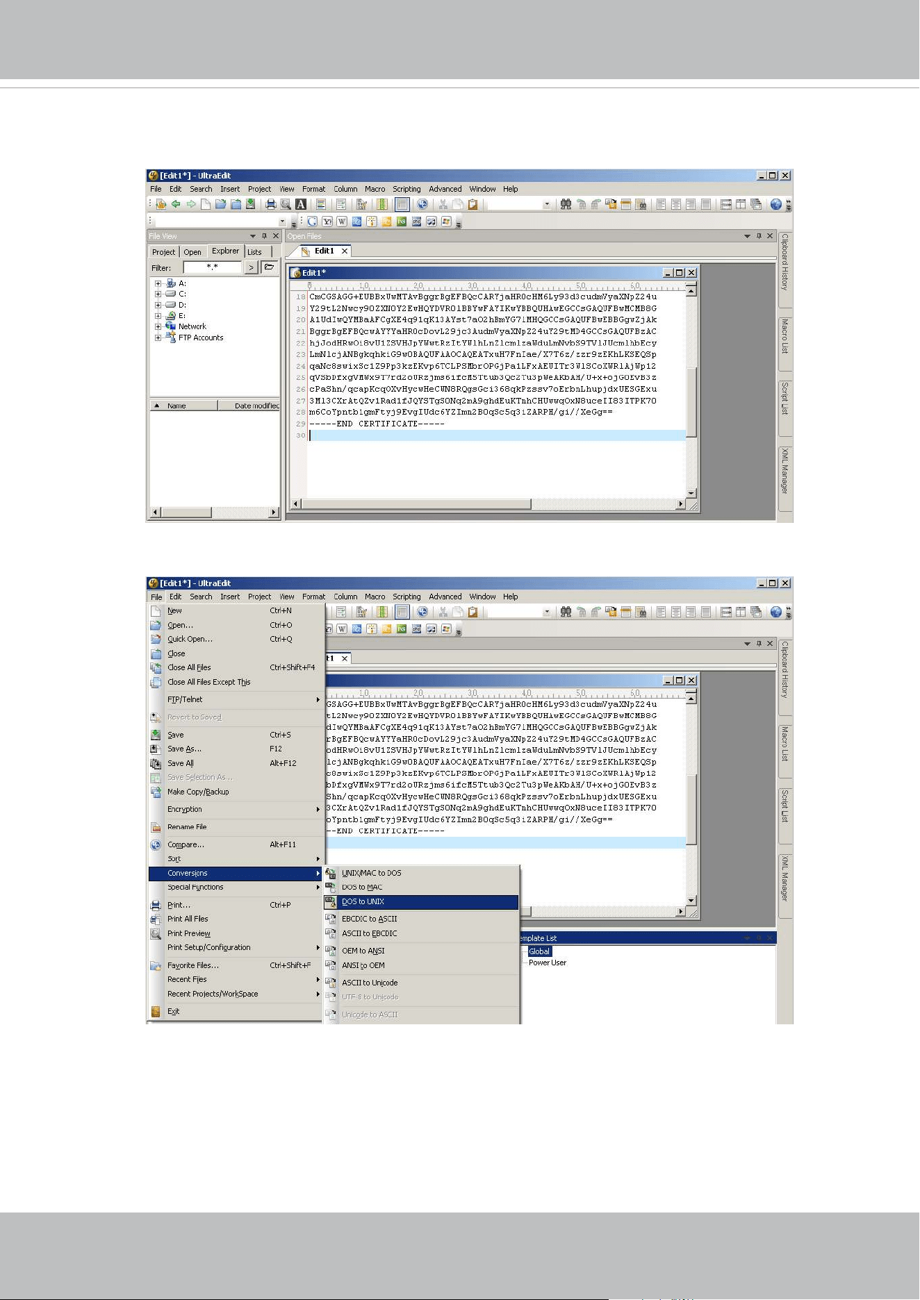
VIVOTEK
124 - User's Manual
7. Open a new edit, paste the certicate contents, and press ENTER at the end of the contents to
add an empty line.
8. Convert le format from DOS to UNIX. Open File menu > Conversions > DOS to Unix.
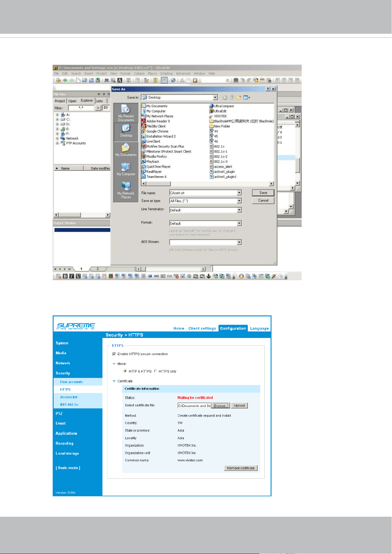
VIVOTEK
User's Manual - 125
9. Save the edit using the “.crt” extension, using a le name like “CAcert.crt.”
10. Return to the original rmware session, use the Browse button to locate the crt certicate le,
and click Upload to enable the certication.
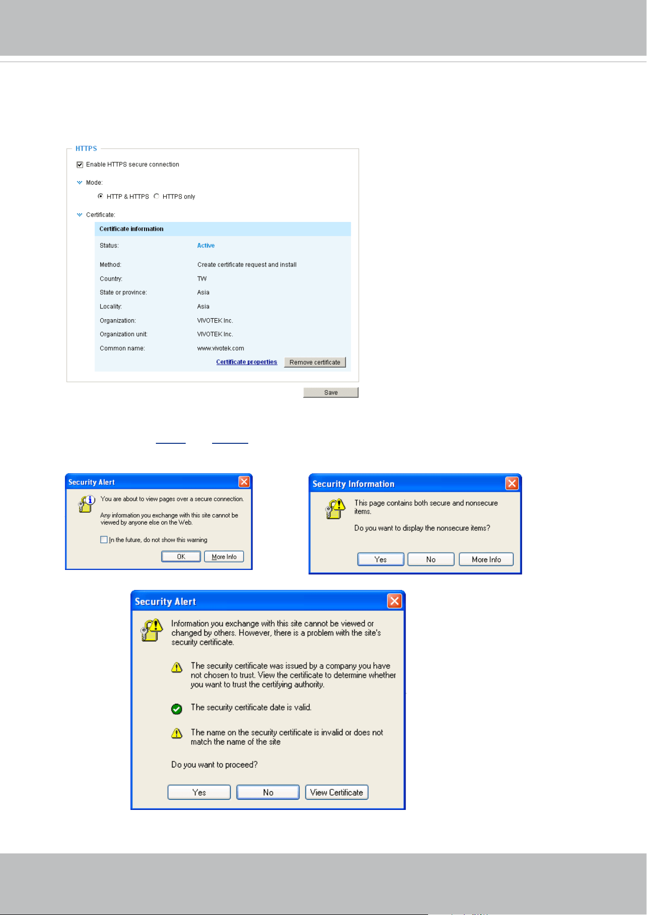
VIVOTEK
126 - User's Manual
11. When the certifice file is successfully loaded, its status will be stated as Active.
Note that
a certicate must have been created and installed before you can click on the “Save"
button for the conguration to take eect.
12.To begin an encrypted HTTPS session, click Home to return to the main page. Change the URL
address from “
http://” to “https://“ in the address bar and press Enter on your keyboard. Some
Security Alert dialogs will pop up. Click OK or Yes to enable HTTPS.
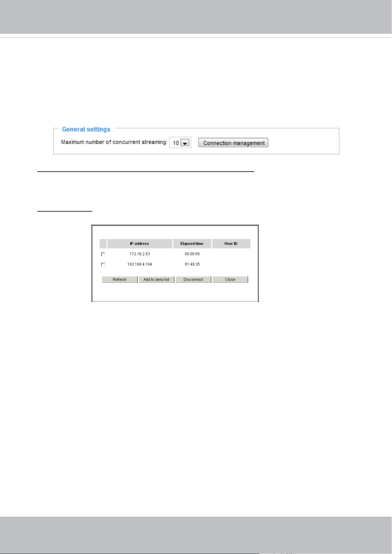
VIVOTEK
User's Manual - 127
Security > Access List
This section explains how to control access permission by verifying the client PC’s IP
address.
General Settings
Maximum number of concurrent streaming connection(s) limited to: Simultaneous live viewing for
1~10 clients (including stream 1 to stream 3). The default value is 10. If you modify the value and
click Save, all current connections will be disconnected and automatically attempt to re-link (IE
Explorer or Quick Time Player).
View Information: Click this button to display the connection status window showing a list of the
current connections. For example:
Note that only consoles that are currently displaying live streaming will be listed in the View
Information list.
■ IP address: Current connections to the Network Camera.
■ Elapsed time: How much time the client has been at the webpage.
■ User ID: If the administrator has set a password for the webpage, the clients have to enter a
user name and password to access the live video. The user name will be displayed in the User
ID column. If the administrator allows clients to link to the webpage without a user name and
password, the User ID column will be empty.
There are some situations that allow clients access to the live video without a user name and
password:
1. The administrator does not set up a root password. For more information about how to set up
a root password and manage user accounts, please refer to Security > User account on page
118.
2. The administrator has set up a root password, but set RTSP Authentication to “disable“. For
more information about RTSP Authentication, please refer to RTSP Streaming on page 105.
3. The administrator has set up a root password, but allows anonymous viewing. For more
information about Allow Anonymous Viewing, please refer to page 118.
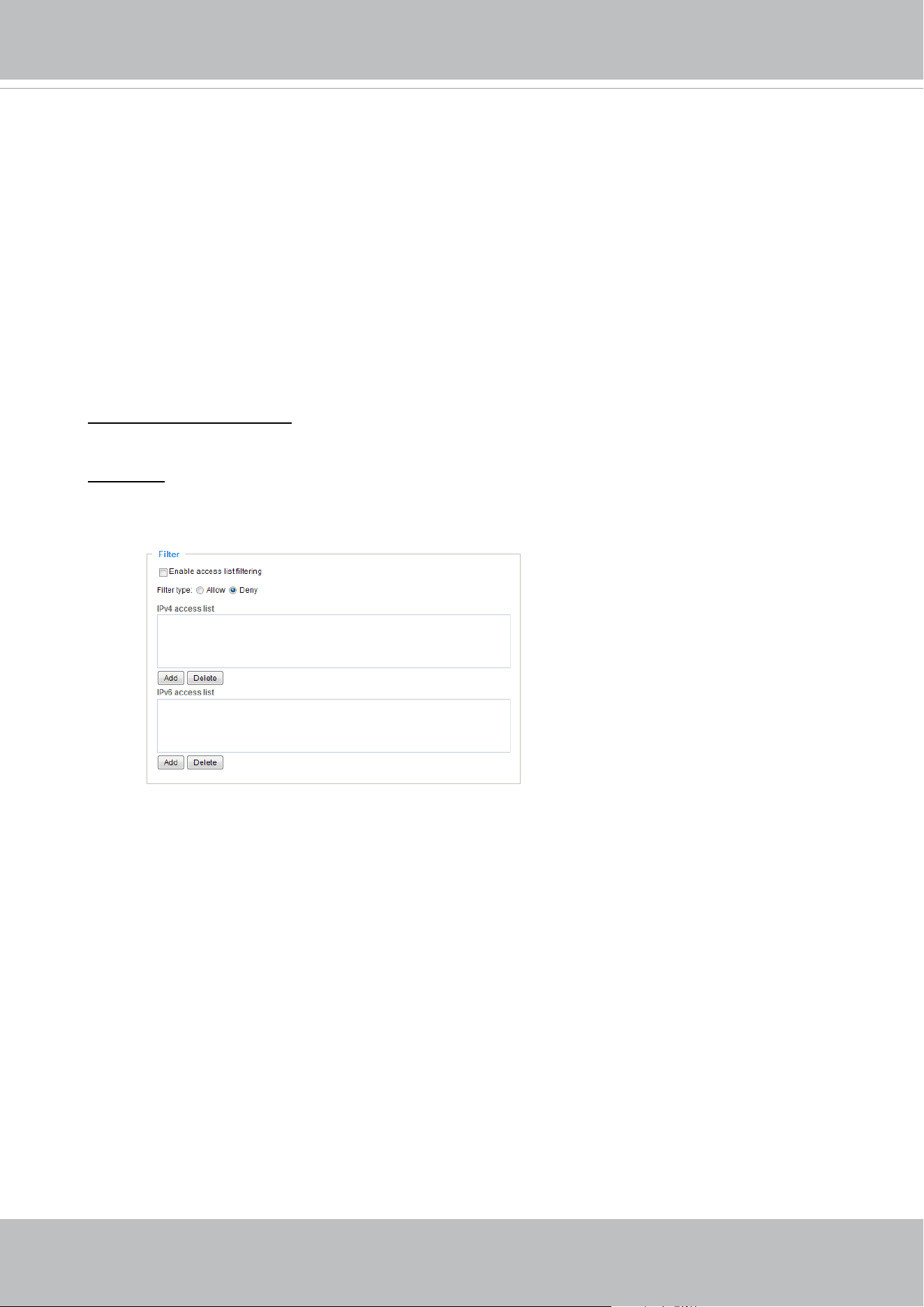
VIVOTEK
128 - User's Manual
■ Refresh: Click this button to refresh all current connections.
■ Add to deny list: You can select entries from the Connection Status list and add them to the
Deny List to deny access. Please note that those checked connections will only be disconnected
temporarily and will automatically try to re-link again (IE Explorer or Quick Time Player). If you
want to enable the denied list, please check Enable access list ltering and click Save in the
rst column.
■ Disconnect: If you want to break o the current connections, please select them and click this
button. Please note that those checked connections will only be disconnected temporarily and
will automatically try to re-link again (IE Explore or Quick Time Player).
Filter
Enable access list ltering: Check this item and click Save if you want to enable the access list
ltering function.
Filter type: Select Allow or Deny as the lter type. If you choose Allow Type, only those clients
whose IP addresses are on the Access List below can access the Network Camera, and the others
cannot. On the contrary, if you choose Deny Type, those clients whose IP addresses are on the
Access List below will not be allowed to access the Network Camera, and the others can.
Then you can Add a rule to the following Access List. Please note that the IPv6 access list column
will not be displayed unless you enable IPv6 on the Network page. For more information about
IPv6 Settings, please refer to Network > General settings on page 97 for detailed information.
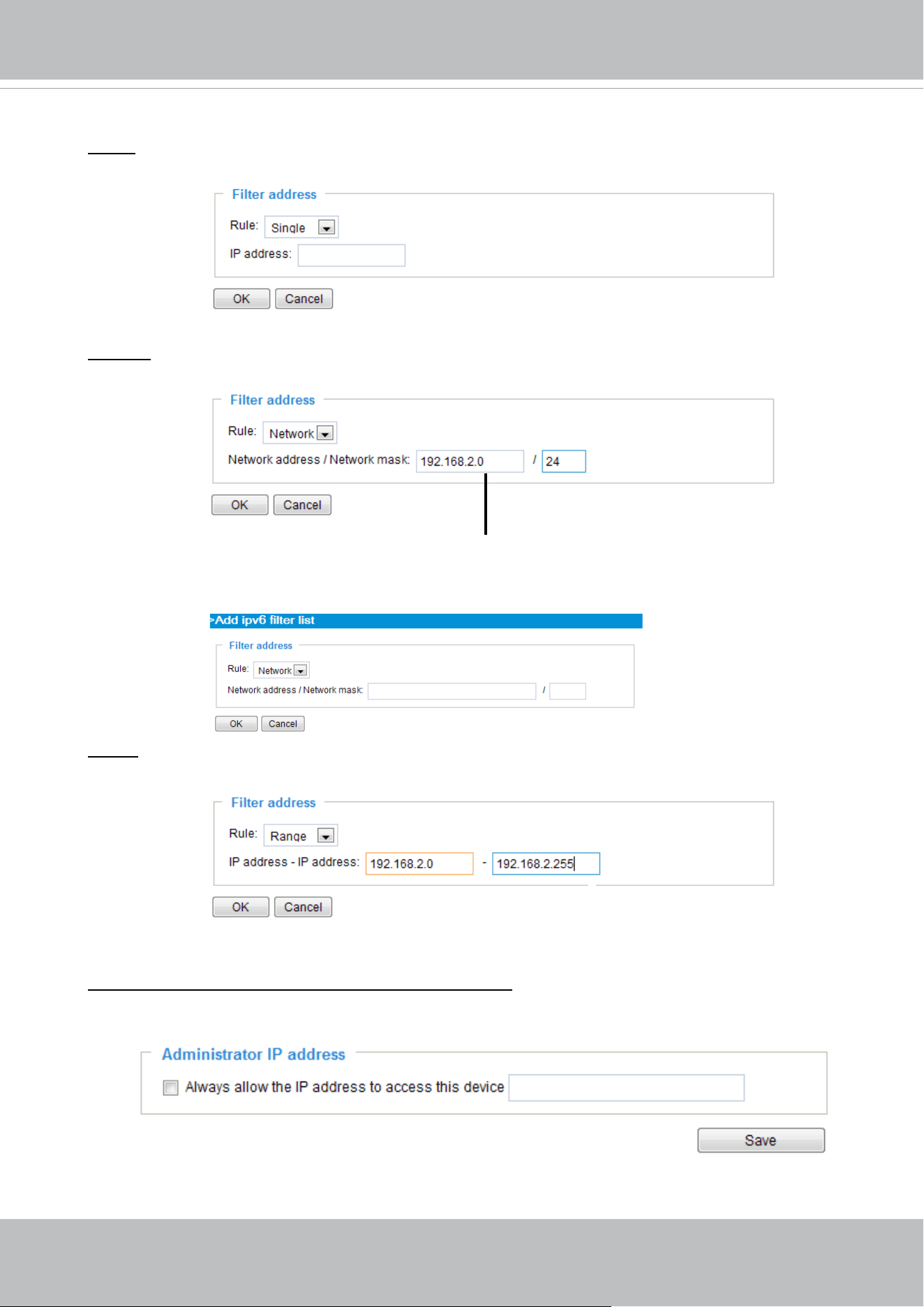
VIVOTEK
User's Manual - 129
Network: This rule allows the user to assign a network address and corresponding subnet mask to
the Allow/Deny List. The address and network mask are written in CIDR format.
For example:
Range: This rule allows the user to assign a range of IP addresses to the Allow/Deny List.
Note: This rule only applies to IPv4 addresses.
For example:
Administrator IP address
Always allow the IP address to access this device: You can check this item and add the
Administrator’s IP address in this eld to make sure the Administrator can always connect to the
device.
IP address range 192.168.2.x will be bolcked.
There are three types of rules:
Single: This rule allows the user to add an IP address to the Allowed/Denied list.
For example:
192.168.2.1
If IPv6 lter is preferred, you will be prompted by the following window. Enter the IPv6 address and
the two-digit prex length to specify the range of IP addresses in your conguration.
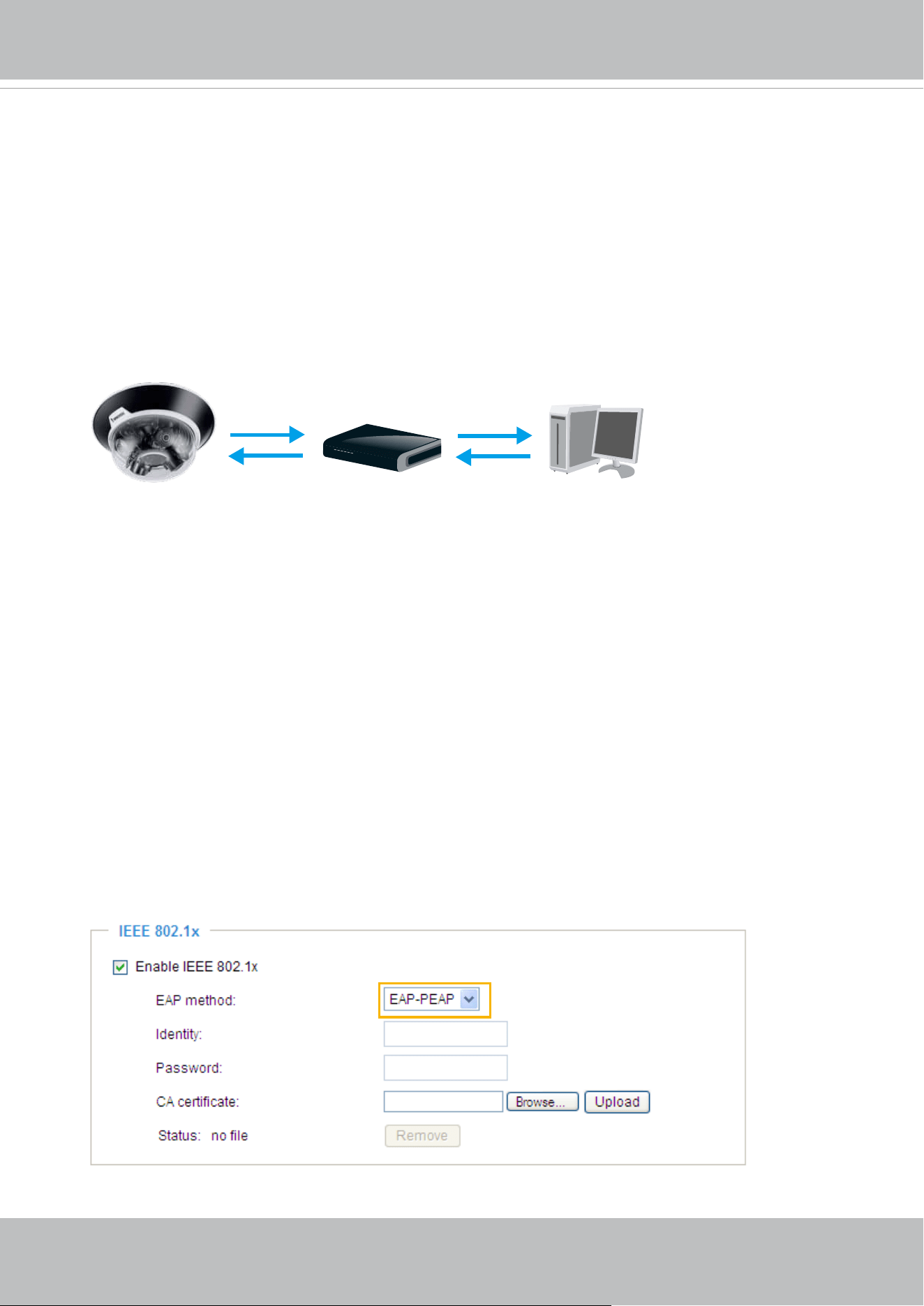
VIVOTEK
130 - User's Manual
Security > IEEE 802.1X
Enable this function if your network environment uses IEEE 802.1x, which is a port-based network
access control. The network devices, intermediary switch/access point/hub, and RADIUS server
must support and enable 802.1x settings.
The 802.1x standard is designed to enhance the security of local area networks, which provides
authentication to network devices (clients) attached to a network port (wired or wireless). If all
certicates between client and server are veried, a point-to-point connection will be enabled; if
authentication fails, access on that port will be prohibited. 802.1x utilizes an existing protocol, the
Extensible Authentication Protocol (EAP), to facilitate communication.
■
The components of a protected network with 802.1x authentication:
1.
Supplicant: A client end user (camera), which requests authentication.
2.
Authenticator (an access point or a switch): A “go between” which restricts unauthorized end
users from communicating with the authentication server.
3.
Authentication server (usually a RADIUS server): Checks the client certificate and decides
whether to accept the end user’s access request.
■
VIVOTEK Network Cameras support two types of EAP methods to perform authentication: EAP-
PEAP and EAP-TLS.
Please follow the steps below to enable 802.1x settings:
1. Before connecting the Network Camera to the protected network with 802.1x, please apply
a digital certificate from a Certificate Authority (i.e., your network administrator) which can be
validated by a RADIUS server.
2. Connect the Network Camera to a PC or notebook outside of the protected LAN. Open the
conguration page of the Network Camera as shown below. Select EAP-PEAP or EAP-TLS as
the EAP method. In the following blanks, enter your ID and password issued by the CA, then
upload related certicate(s).
Supplicant
(Network Camera)
Authenticator
(Network Switch)
Authentication Server
(RADIUS Server)
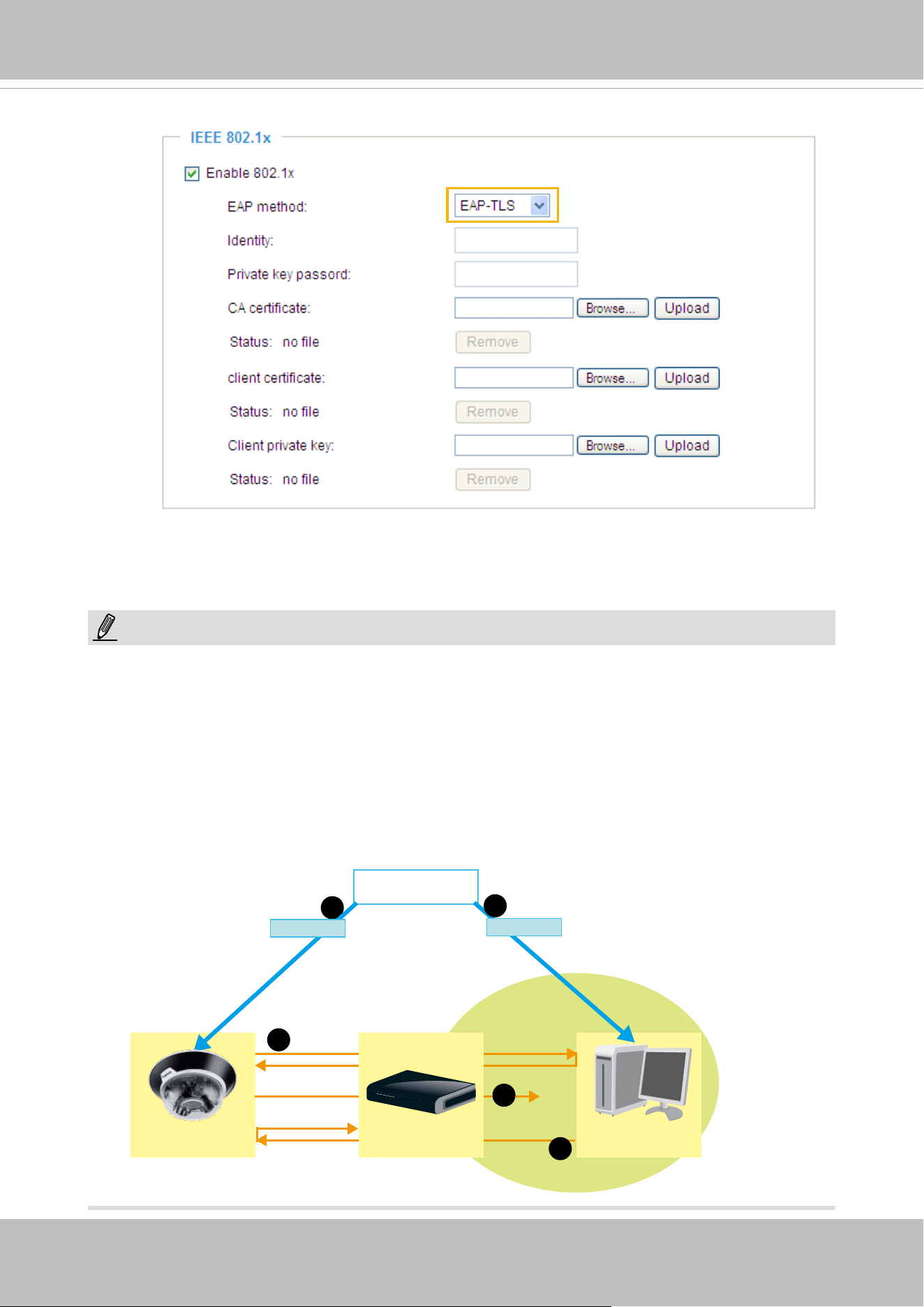
VIVOTEK
User's Manual - 131
3. When all settings are complete, move the Network Camera to the protected LAN by connecting
it to an 802.1x enabled switch. The devices will then start the authentication automatically.
VIVOTEK
Network Camera
RADIUS Server
Certificate Authority
(CA)
Protected LAN
Certificate
1
1
2
3
4
Network Switch
Certificate
NOTE:
► The authentication process for 802.1x:
1. The Certicate Authority (CA) provides the required signed certicates to the Network Camera
(the supplicant) and the RADIUS Server (the authentication server).
2. A Network Camera requests access to the protected LAN using 802.1X via a switch (the
authenticator). The client oers its identity and client certicate, which is then forwarded by the
switch to the RADIUS Server, which uses an algorithm to authenticate the Network Camera and
returns an acceptance or rejection back to the switch.
3. The switch also forwards the RADIUS Server’s certicate to the Network Camera.
4. Assuming all certicates are validated, the switch then changes the Network Camera’s state to
authorized and is allowed access to the protected network via a pre-congured port.
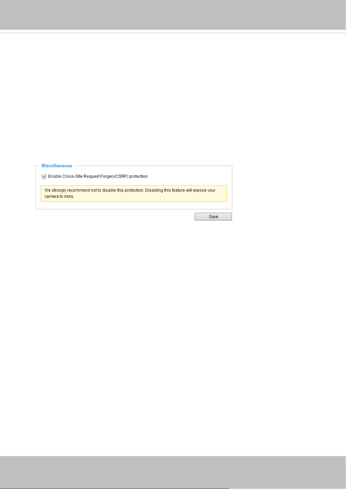
VIVOTEK
132 - User's Manual
Security > Miscellaneous
The embedded TrendMicro utitlity provides the protection against Cross-Site Request
Forgery. Cross-site request forgery is also known as one-click attack or session riding and
is abbreviated as CSRF. CSRF is a type of malicious exploit of a website, in this case, the
camera. Unauthorized commands are transmitted from a user that the web application
trusts, using the mechanism of forging a trusted user's own request with a request
containing his own cookies, etc. Different ways can be used for a malicious website to
transmit such commands. They can be specially-crafted image tags, hidden forms, and
JavaScript XMLHttpRequests. The malicious attack can occur without users' interaction or
even knowing it.
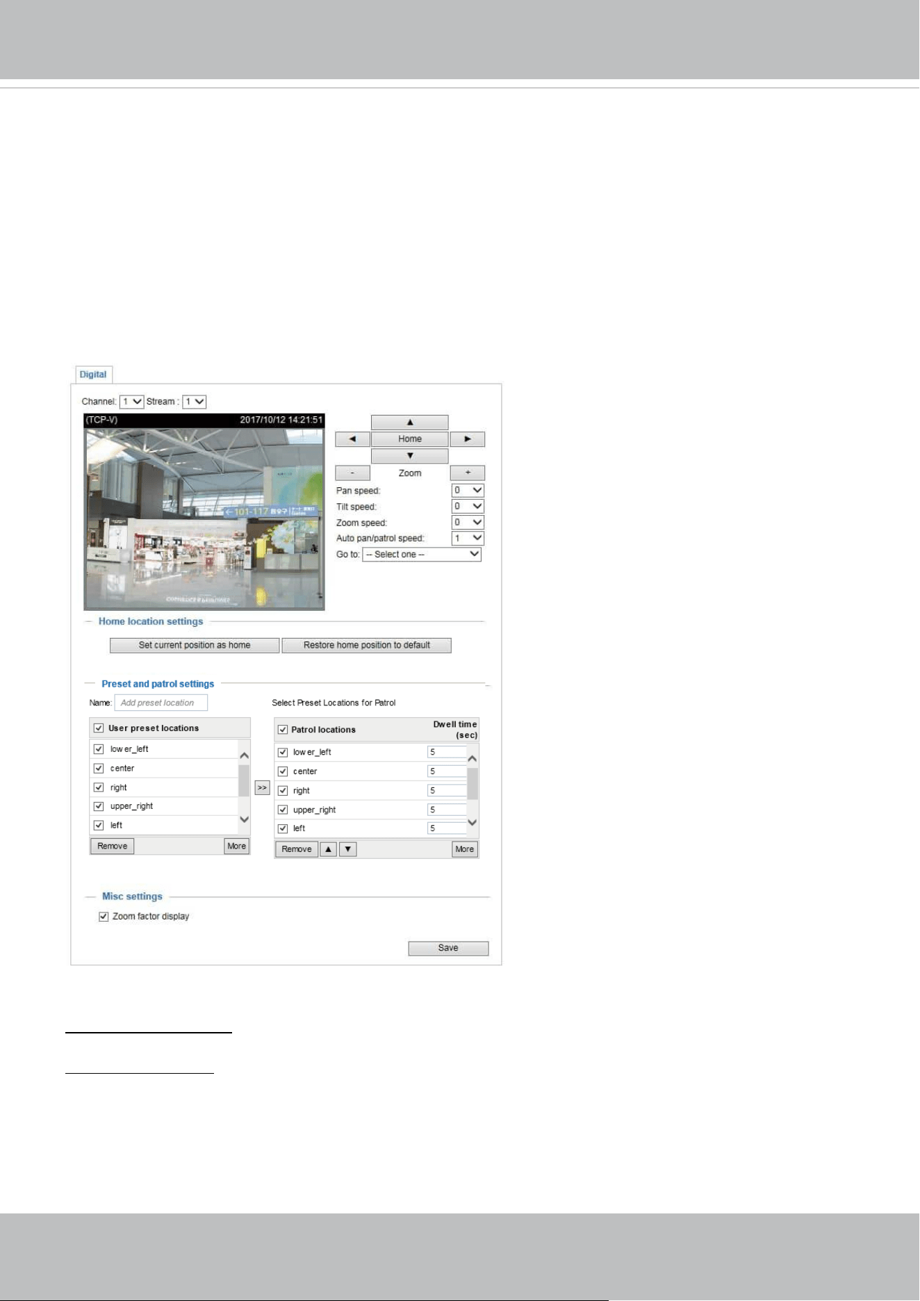
VIVOTEK
User's Manual - 133
PTZ > PTZ settings
This section explains how to control the Network Camera’s Pan/Tilt/Zoom operation.
Digital: Control the e-PTZ operation. Within a eld of view, it allows users to quickly move the
focus to a target area for close-up viewing without physically moving the camera.
Digital PTZ Operation (E-PTZ Operation)
The e-PTZ control settings section will be displayed as shown below:
For e-PTZ related details, please refer to page 135.
Auto pan/patrol speed: Select the speed from 1~5 (slow/fast) to set up the Auto pan/patrol speed control.
Zoom factor display
If you check this item, the zoom indicator will be displayed on the home page when you zoom in/out the
live viewing window as the picture shown on the next page.
When completed with the e-PTZ settings, click Save to enable the settings on this page.
x1.8
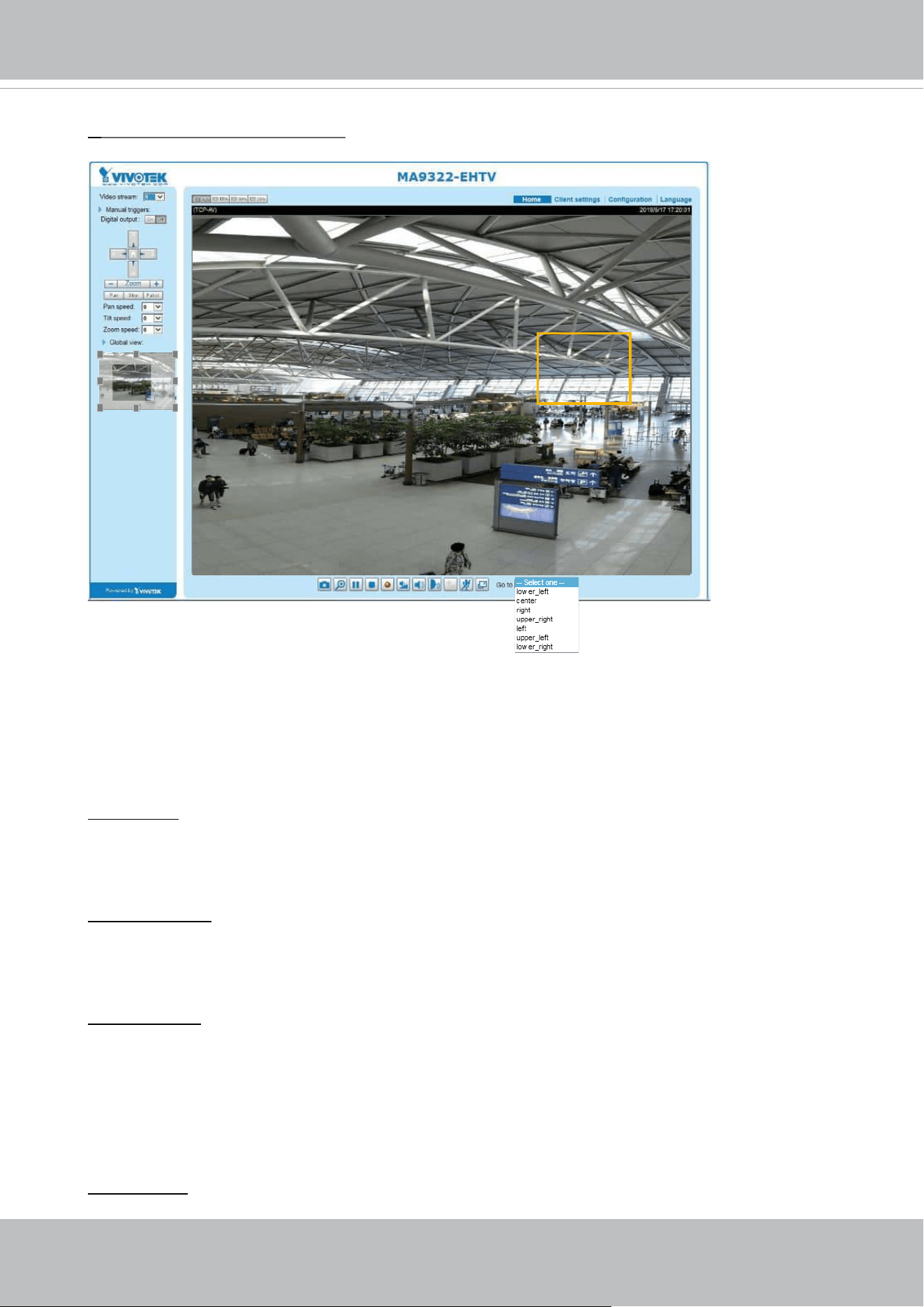
VIVOTEK
134 - User's Manual
Home page in the E-PTZ Mode
■ The e-Preset Positions will also be displayed on the home page. Select one from the drop-down
list, and the Network Camera will move to the selected position.
■ If you have set up dierent preset positions for dierent streams, you can select one of the video
streams to display its separate preset positions.
Global View
In addition to using the e-PTZ control panel, you can also use the mouse to drag or resize the
floating frame to pan/tilt/zoom the viewing region. The live view window will also move to the
viewing region accordingly.
Moving Instantly
If you check this item, the live view window will switch to the new viewing region instantly after you
move the oating frame. If not selected, the process of moving from one position to another will be
shown.
Click on Image
The e-PTZ function also supports “Click on Image“. When you click on any point of the Global View
Window or Live View Window, the viewing region will also move to that point.
Note that the”Click on Image” function only applies when you have congured a smaller “Region
of Interest” out of the maximum output frame! e.g., an 800 x 600 region from out of the camera’s
maximum frame size.
Patrol button: Click this button, then the Network Camera will patrol among the selected preset
positions continuously.
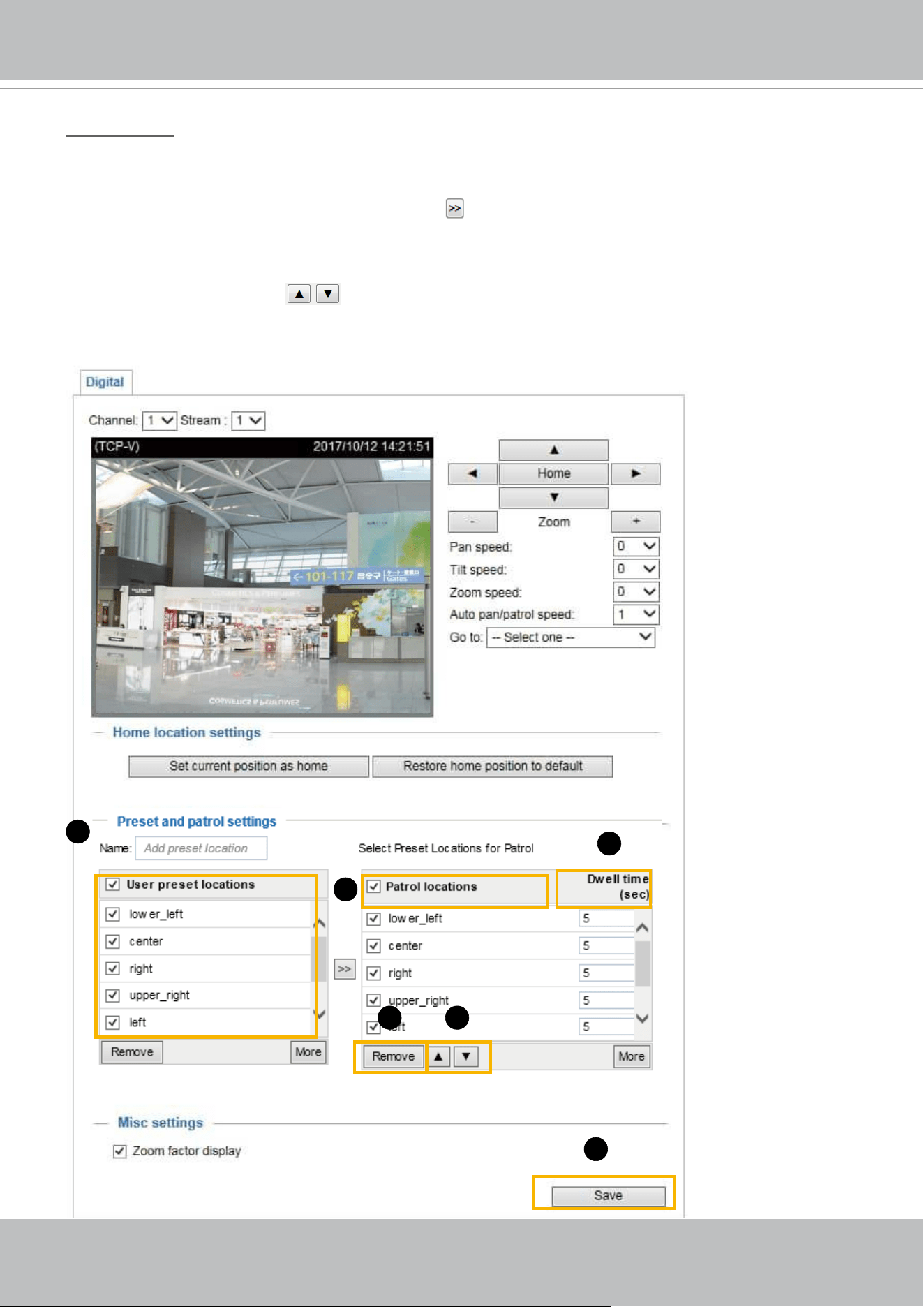
VIVOTEK
User's Manual - 135
Patrol settings
You can select some preset positions for the Network Camera to patrol.
Please follow the steps below to set up a patrol schedule:
1. Select the preset locations on the list, and click
.
2. The selected preset locations will be displayed on the Patrol locations list.
3. Set the Dwelling time for the preset location during an auto patrol.
4. If you want to delete a preset location from the Patrol locations list, select it and click Remove.
5. Select a location and click
to rearrange the patrol order.
6. Select patrol locations you want to save in the list and click Save to enable the patrol settings.
7. To implement the patrol schedule, please go to homepage and click on the Patrol button.
x1.8
1
2
6
54
3

VIVOTEK
136 - User's Manual
NOTE:
• The Preset Positions will also be displayed on the Home page. Select one from the Go to
menu, and the Network Camera will move to the selected preset position.
• Click Patrol: The Network Camera will patrol along the selected positions repeatedly.
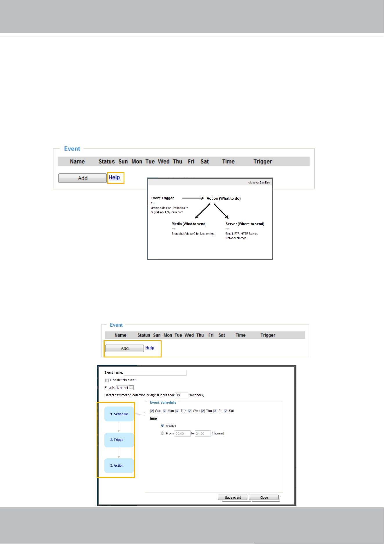
VIVOTEK
User's Manual - 137
Event > Event settings
This section explains how to congure the Network Camera to respond to particular situations
(event). A typical application is that when a motion is detected, the Network Camera sends
buffered images to an FTP server or e-mail address as notifications. Click on Help, there is
an illustration shown in the pop-up window explaining that an event can be triggered by many
sources, such as motion detection or external digital input devices. When an event is triggered,
you can specify what type of action that will be performed. You can configure the Network
Camera to send snapshots or videos to your email address or FTP site.
Event
To congure an event with reactive measures such as recording video or snapshots, it is necessary to
congure the server and media settings so that the Network Camera will know what action to take (such
as which server to send the media les to) when a trigger is activated. An event is an action initiated
by a user-dened trigger source
.
In the Event column, click Add to open the event settings window.
Here you can arrange three elements -- Schedule, Trigger, and Action. A total of 3 event settings can be
congured.
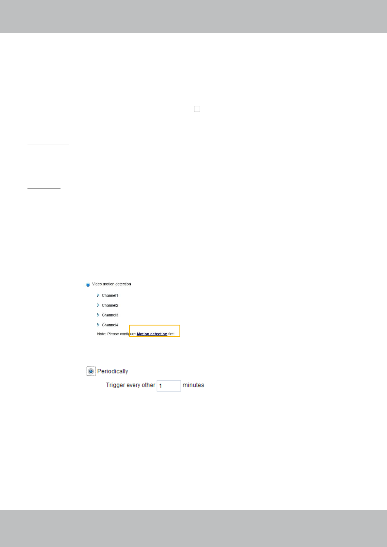
VIVOTEK
138 - User's Manual
■ Event name: Enter a name for the event setting.
■ Enable this event: Select this checkbox to enable the event setting.
■ Priority: Select the relative importance of this event (High, Normal, or Low). Events with a higher
priority setting will be executed rst.
■ Detect next motion detection or digital input after
seconds: Enter the duration in seconds to pause
motion detection after a motion is detected. This can prevent event-related actions to take place too
frequently.
1. Schedule
Specify the period of time during which the event trigger will take eect. Please select the days of the
week and the time in a day (in 24-hr time format) for the event triggering schedule. For example, you
may prefer an event to be triggered only during the o-oce hours.
2. Trigger
This is the cause or stimulus which denes when to trigger the Network Camera. The trigger source can
be congured to use the Network Camera’s built-in motion detection mechanism or external digital input
devices.
There are several choices of trigger sources as shown on the next page.
Select the item to display the
detailed conguration options.
■ Video motion detection
This option makes use of the built-in motion detection mechanism as a trigger source. To enable this
function, you need to congure a Motion Detection Window rst. For more information, please refer to
Motion Detection on page 154 for details.
■ Periodically
This option allows the Network Camera to trigger periodically for every other dened minute. Up to 999
minutes are allowed.
■ Digital input
This option allows the Network Camera to use an external digital input device or sensor as a trigger
source. Depending on your application, there are many choices with digital input devices on the market
which help detect changes in temperature, vibration, sound, light, etc.
■ System boot
This option triggers the Network Camera when the power to the Network Camera is disconnected and
re-connected.
■ Recording notify
This option allows the Network Camera to trigger when the recording disk is full or when recording
starts to overwrite older data.
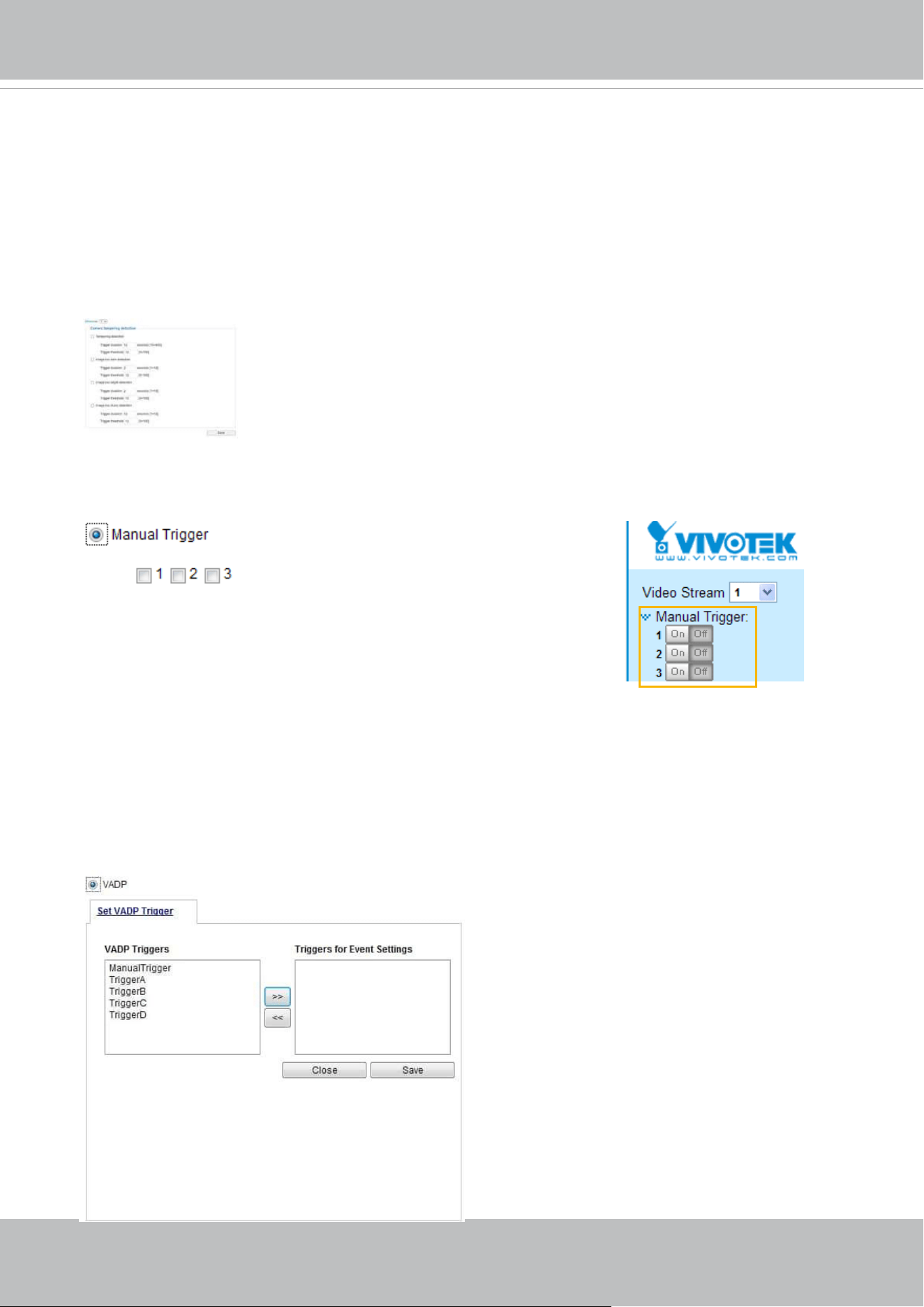
VIVOTEK
User's Manual - 139
■ Camera tampering detection
This option allows the Network Camera to trigger when the camera detects that it is being tampered
with. To enable this function, you need to congure the Tampering Detection option rst. Please refer
to page 158 for detailed information.
■ Manual Triggers
This option allows users to enable event triggers manually by clicking the on/off button on the
homepage. Please congure 1 to 3 associated events before using this function.
■ Audio detection
A preset threshold can be congured with an external microphone as the trigger to system event. The
triggering condition can be an input exceeding or falling below a threshold. Audio detection can take
place as a complement to motion detection or as a method to detect activities not covered by the
camera's view.
■ VADP
It is presumed that you already uploaded and enabled the VADP modules before you can associatee
VADP triggers with an Event setting.
Click on the Set VADP Trigger button to open the VADP setup menu. The triggering conditions
available with 3rd-party software modules known as VADP will be listed. Use the arrow buttons to
select these triggers. Users may implant these modules for different purposes such as triggering
motion detection, or applications related to video analysis, etc. Please refer to page 161 for the
conguration options with VADP modules.
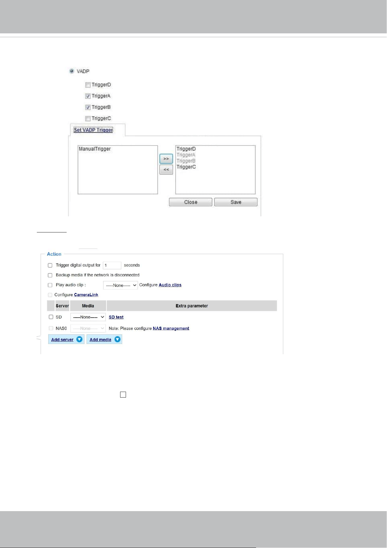
VIVOTEK
140 - User's Manual
3. Action
Dene the actions to be performed by the Network Camera when a trigger is activated.
■ Trigger digital output for
seconds
Select this option to turn on the external digital output device when a trigger is activated. Specify
the length of the trigger interval in the text box.
■ Backup media if the network is disconnected
Select this option to backup media le on SD card if the network is disconnected. This function
will only be displayed after you set up a network storage (NAS). The media to back up can
include snapshot images, video, or system logs depending on your event settings.
Once the triggers are congured, they will be listed under the VADP option.
■ Play audio clip:
A pre-loaded audio clip can be congured to be played when one triggering condition is met. For
example, playing a warning message to deter an intruder.

VIVOTEK
User's Manual - 141
■ Congure CameraLink
The camera can be associated with another camera with responsive actions. For example, if a
thermal camera detects some abnormal situations, e.g., a re, the camera can tell another camera,
say, a PTZ camera to move to a preset position to observe the current situation.
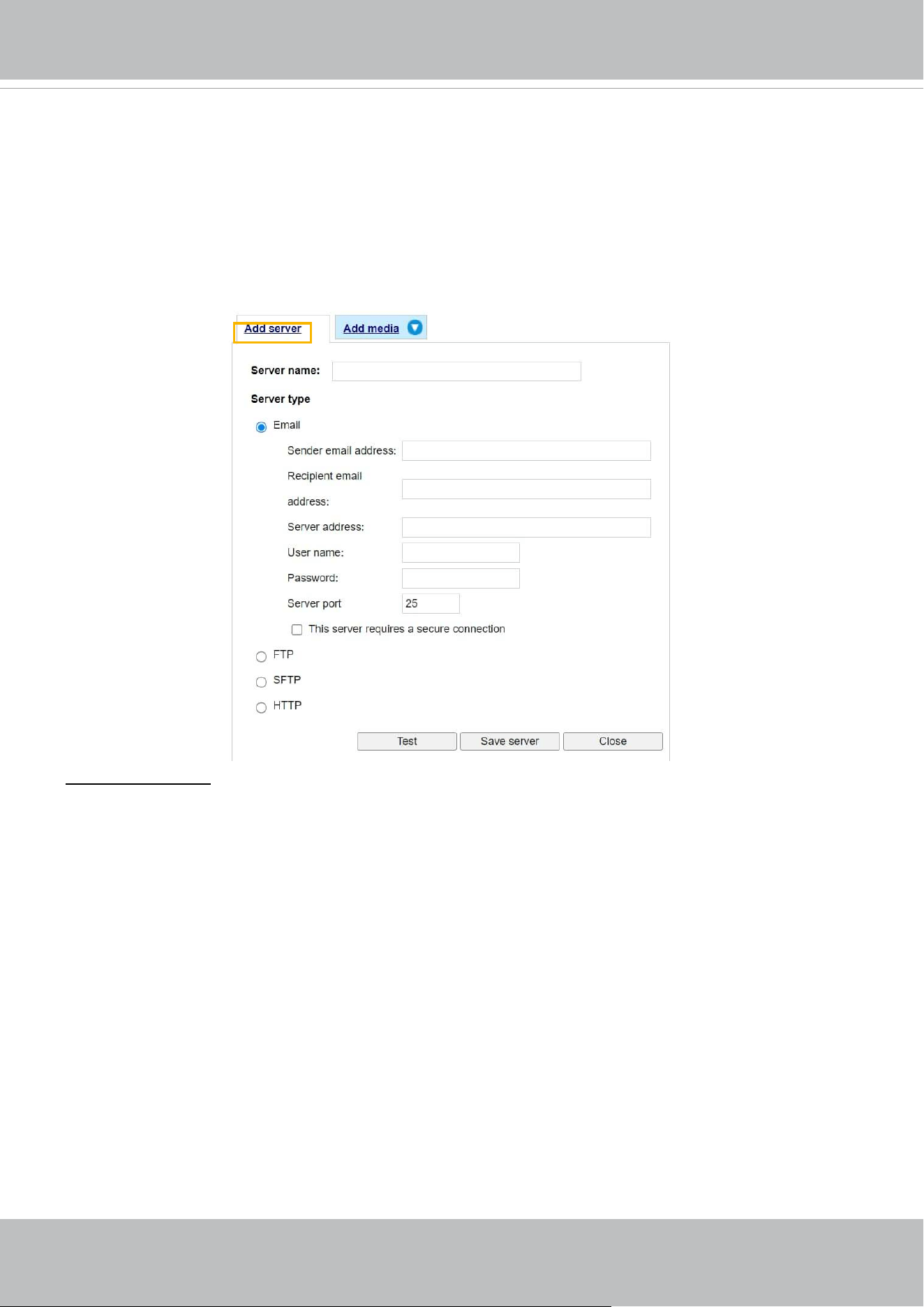
VIVOTEK
142 - User's Manual
Add server
It is necessary to congure the server and media settings so that the Network Camera will know what
action to take (such as which server to send the media les to) when a trigger is activated. Click
Add
server
to open the server setting window. You can specify where the notication messages are sent to
when a trigger is activated. A total of 5 server settings can be congured.
There are four choices of server types available: Email, FTP, HTTP, and Network storage.
Select the item
to display the detailed conguration options. You can congure either one or all of them.
Server type - Email
Select to send the media les via email when a trigger is activated.
■ Server name: Enter a name for the server setting.
■ Sender email address: Enter the email address of the sender.
■ Recipient email address: Enter the email address of the recipient.
■ Server address: Enter the domain name or IP address of the email server.
■ User name: Enter the user name of the email account if necessary.
■ Password: Enter the password of the email account if necessary.
■ Server port: The default mail server port is set to 25. You can also manually set another port.
If your SMTP server requires a secure connection (SSL), select This server requires a secure
connection (SSL).
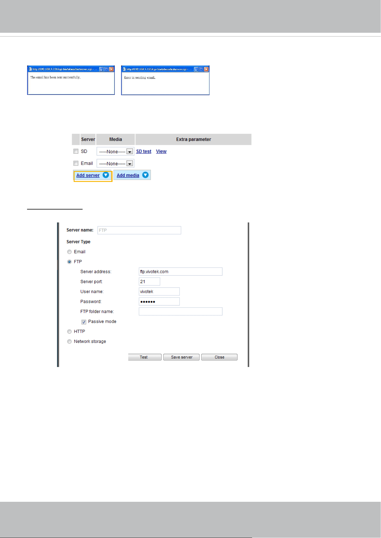
VIVOTEK
User's Manual - 143
To verify if the email settings are correctly congured, click Test. The result will be shown in a pop-up
window. If successful, you will also receive an email indicating the result.
Click Save server to enable the settings.
Note that after you congure the rst event server, the new event server will automatically display on the
Server list. If you wish to add other server options, click Add server.
Server type - FTP
Select to send the media les to an FTP server when a trigger is activated.
■ Server name: Enter a name for the server setting.
■ Server address: Enter the domain name or IP address of the FTP server.
■ Server port: By default, the FTP server port is set to 21. It can also be assigned to another port number
between 1025 and 65535.
■ User name: Enter the login name of the FTP account.
■ Password: Enter the password of the FTP account.
■ FTP folder name
Enter the folder where the media les will be placed. If the folder name does not exist, the Network
Camera will automatically create one on the FTP server.
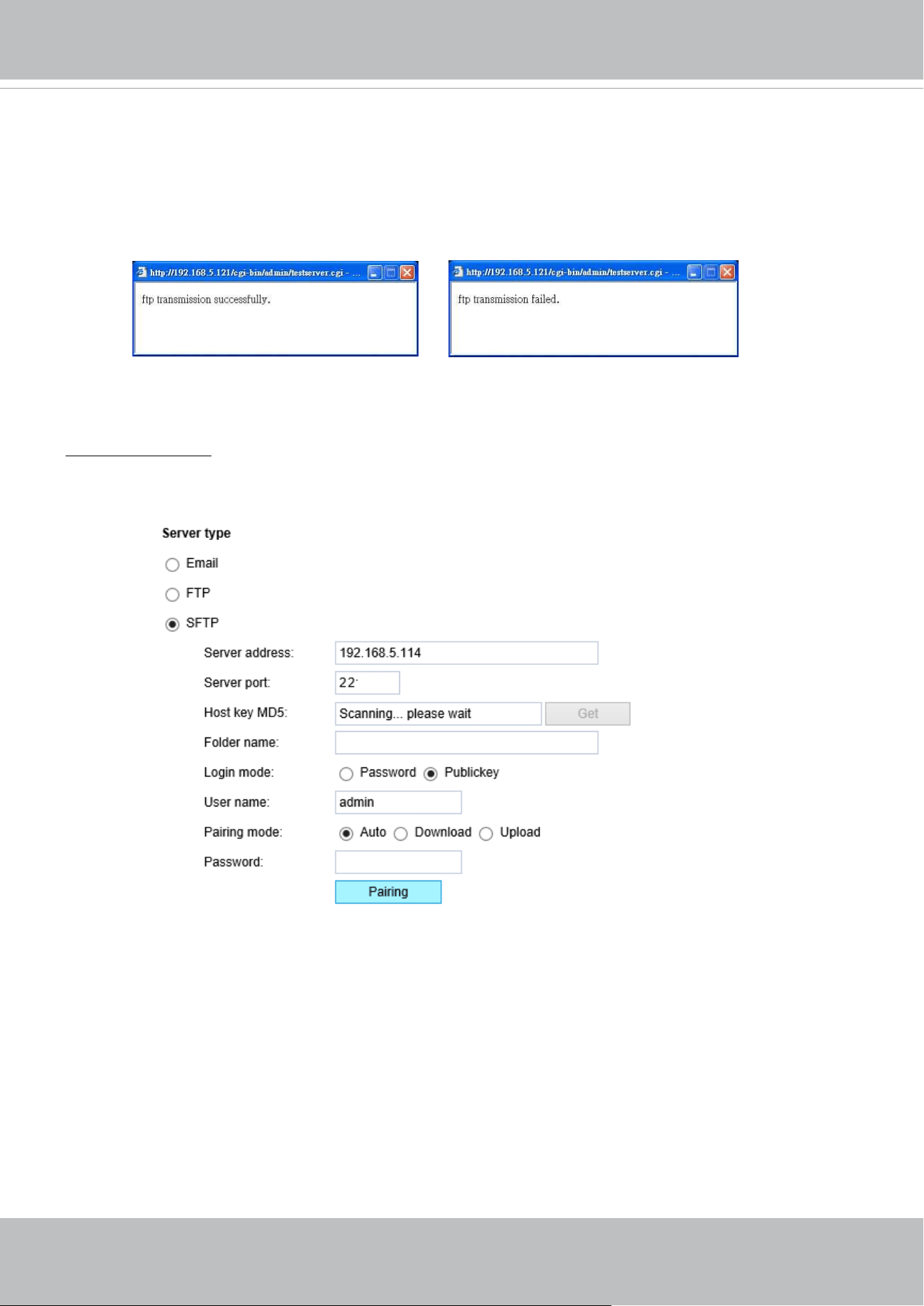
VIVOTEK
144 - User's Manual
■ Passive mode
Most firewalls do not accept new connections initiated from external requests. If the FTP server
supports passive mode, select this option to enable passive mode FTP and allow data transmission to
pass through the rewall. The rmware default has the Passive mode checkbox selected.
To verify if the FTP settings are correctly congured, click Test. The result will be shown in a pop-up
window as shown below. If successful, you will also receive a test.txt le on the FTP server.
Click Save server to enable the settings.
Server type - SFTP
Select to send the media files to an SFTP (Secure File Transfer Protocol) server when a trigger is
activated. This page contains the client side settings.
■ Server address: Enter the SFTP server address in either the domain name or IP address.
■ Server port: By default, the FTP server port is set to 22. It can also be assigned to another port number
between 1025 and 65535.
■ Host key MD5: You have the option to use public/private key authentication instead of a username and
password to connect to the server. This option requires that you have a private/public SSH key pair,
and that the public key is in place on your SFTP server.
If you wish to Use key authentication for this SFTP server, click the Get (Read Fingerprint) button to
request the public key ngerprint from the server. The host key MD5 is a hash of the FTP server’s
public key, which the camera stores in order to verify that it is connecting to the correct SFTP server.
You can copy that ngerprint and save it for later reference.
The max. length of MD5 ngerprint is 47 characters.
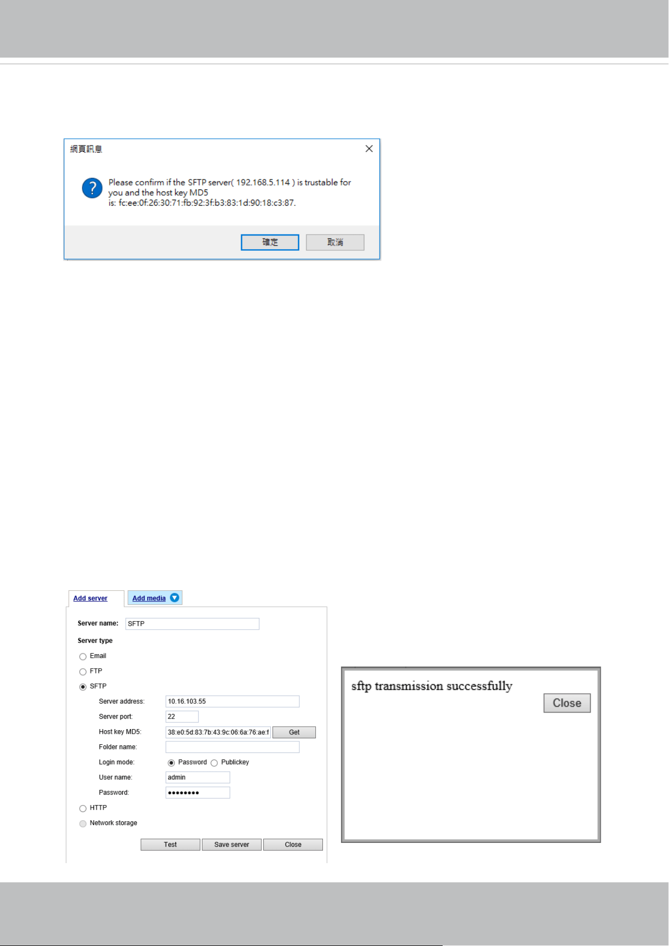
VIVOTEK
User's Manual - 145
Password mode:
■ User name: Enter the login name of the SFTP account.
■ Password: Enter the password of the SFTP account.
■ Folder name
Enter the folder where the media file will be placed. If the folder name does not exist, the Network
Camera will create one on the SFTP server.
Use backslash “\” when you need to specify a path. Leave it blank to use the SFTP server’s default
root directory. The max. length of folder name is 128 characters.
■ Login mode
Select a Login mode as either the Password or the Public key mode.
When using SFTP, you can authenticate using a public/private SSH key pair instead of a password.
If key authentication is not enabled, you need to specify a password instead. The administrator of the
SFTP server will need to manually add the corresponding public key to the SFTP server.
If key authentication is not preferred, you can specify a username and password in the section below.
An RSA key ngerprint will look like this: da:47:93:b4:3a:90:5b:50:1f:20:a8:f9:b7:a1:d0:e1. Verify if this
is the SFTP server you want to connect to.
Use the Test button to test the connectivity. When
done, enter the server name and click the Save server
button to preserve your settings.
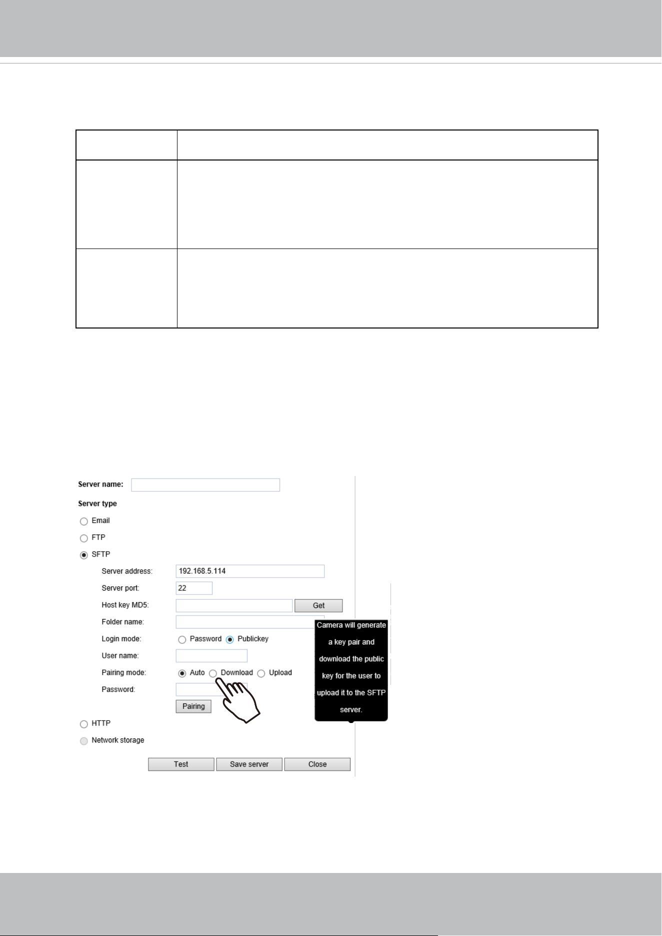
VIVOTEK
146 - User's Manual
Publickey mode:
Selecting the Public key mode will bring up the Pairing mode options: Auto, Download, Upload.
Auto Camera will generate a key pair and auto pair public key with the SFTP
server.
Download Camera will generate a key pair and download the public key for the user to
upload it to the SFTP server. The supported formats are: ED25519 (default.
Elliptic curve signature scheme Edwards-curve Digital Signature Algorithm;
with faster key creation, encryption and decryption), RSA (Rivest–Shamir–
Adleman, with greater portability), ECDSA (Elliptic Curve Digital Signature
Algorithm).
Upload Upload the private key here and upload the public key to the SFTP server.
A private key is a guarded secret and it can be stored on disk in an encrypted
form. A passphrase is used in order to decrypt it. It is a login password to the
SSH server, the passphrase is only used to decrypt the private key on the
local system. The passphrase is not transmitted over the network.
When using SFTP, you can authenticate using a public/private SSH key pair instead of a
password. If key authentication is not enabled, you need to specify a password instead. The
administrator of the SFTP server will need to manually add the corresponding public key to the
SFTP server.
The key benet of a key-based authentication is that instead of a using a password, you are less
vulnerable to brute-force attacks and you do not expose valid credentials, if the server has been
compromised.
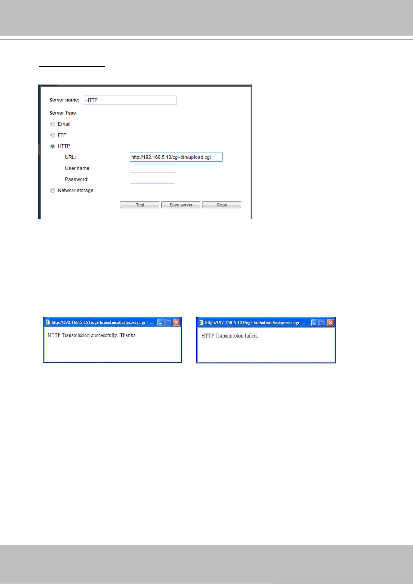
VIVOTEK
User's Manual - 147
Server type - HTTP
Select to send the media les to an HTTP server when a trigger is activated.
■ Server name: Enter a name for the server setting.
■ URL: Enter the URL of the HTTP server.
■ User name: Enter the user name if necessary.
■ Password: Enter the password if necessary.
To verify if the HTTP settings are correctly congured, click Test. The result will be shown in a pop-
up window as shown below. If successful, you will receive a test.txt le on the HTTP server.
Click Save server to enable the settings.
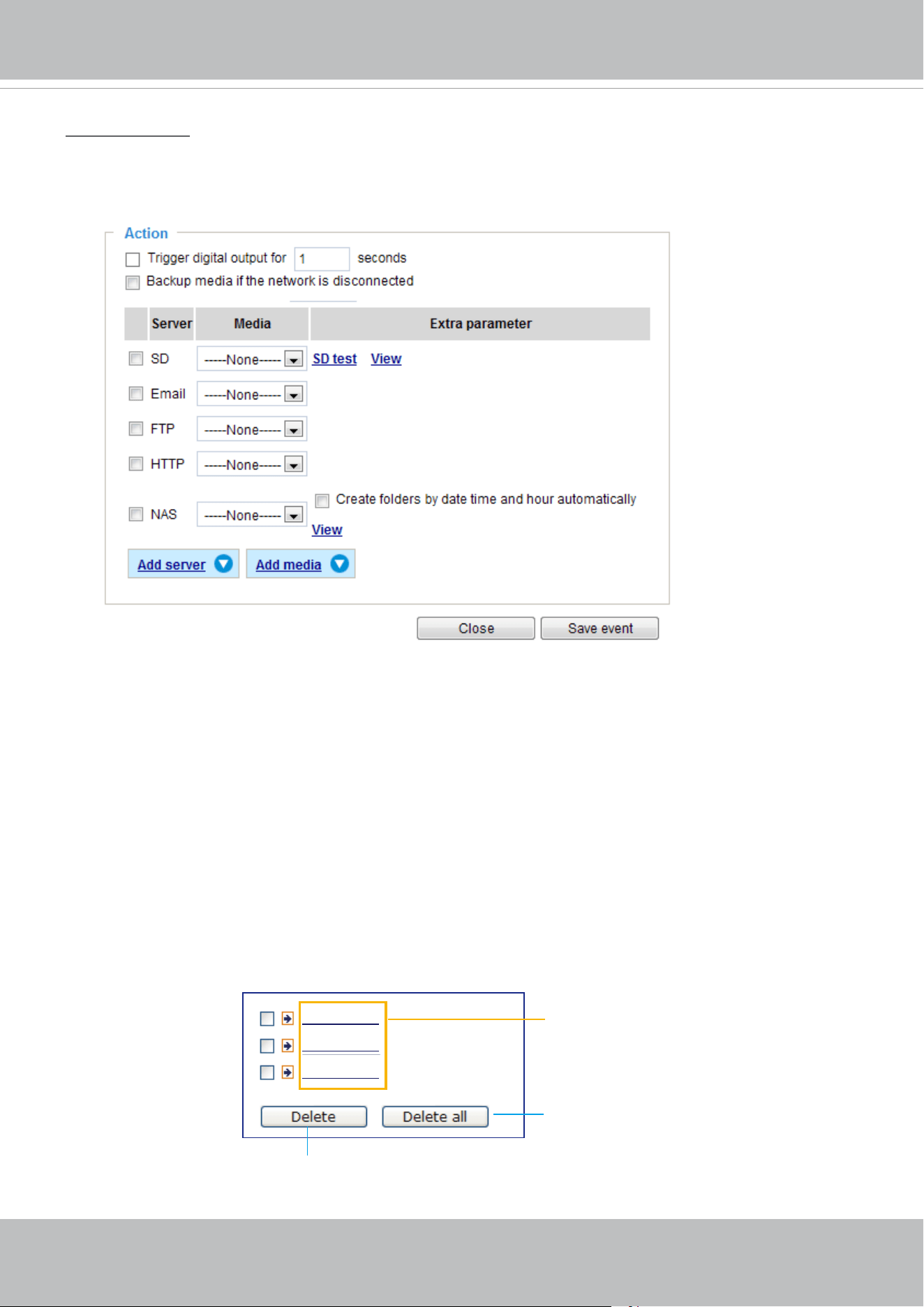
VIVOTEK
148 - User's Manual
Network storage:
Select to send the media les to a networked storage when a trigger is activated. Please refer to NAS
server on page 167 for details. Note that only one NAS server can be congured.
Click Save server to enable the settings.
■ SD Test: Click to test your SD card. The system will display a message indicating the result as a
success or a failure. If you want to use your SD card for local storage, please format it before use.
Please refer to page 150 for detailed information.
■ View: Click this button to open a le list window. This function is only for SD card and Network Storage.
If you click the View button for an SD card, a Local storage page will prompt so that you can manage
the recorded les on SD card. For more information about Local storage, please refer to page 169.
If you click the View button for a Network storage, a le directory window will prompt for you to view
recorded data on Network storage. For detailed illustration, please refer to the next page.
■ Create folders by date, time, and hour automatically: If you select this item, the system will
automatically create folders by the date when video footages are stored onto the networked storage.
The following is an example of a le destination with video clips:
20190120
20190121
20190122
Click to delete selected items
Click to delete all recorded data
The format is: YYYYMMDD
Click to open the directory
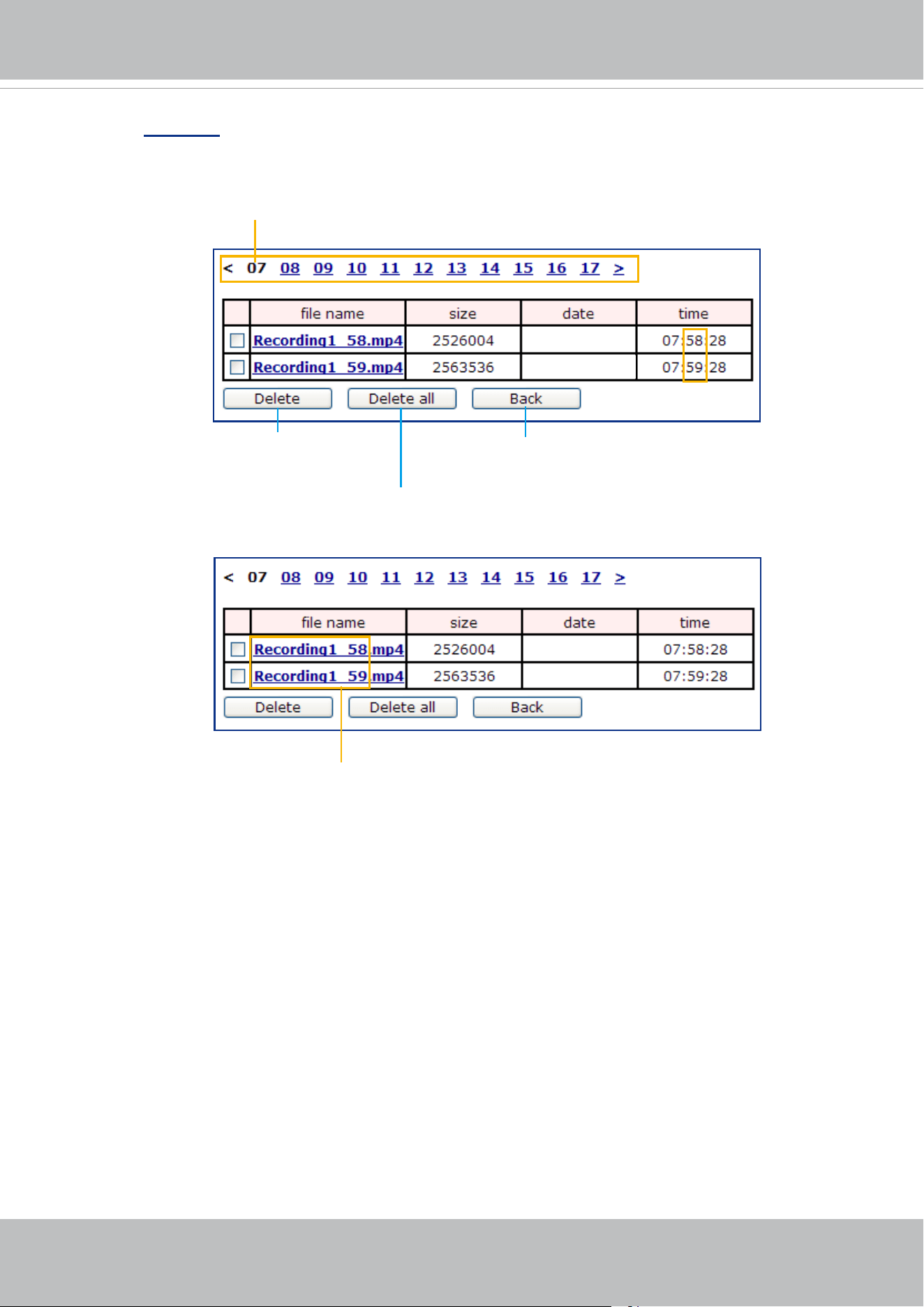
VIVOTEK
User's Manual - 149
Click 20190120 to open the directory:
Click to delete
selected items
Click to delete all
recorded data
Click to go back to the previous
level of the directory
The format is: HH (24r)
Click to open the le list for that hour
The format is: File name prex + Minute (mm)
You can set up the le name prex on Add media page. Please
refer to
next page for detailed information.
2019/01/20
2019/01/20
2019/01/20
2019/01/20
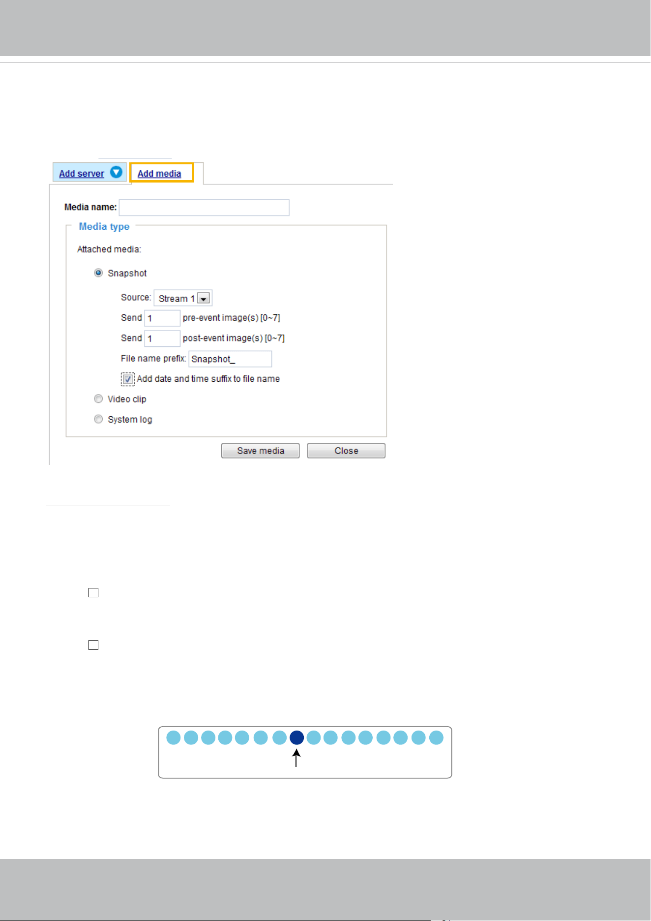
VIVOTEK
150 - User's Manual
Add media
Click
Add media
to open the media setting window. You can specify the type of media that will be
sent when a trigger is activated. A total of 5 media settings can be congured. There are three choices
of media types available: Snapshot, Video Clip, and System log.
Select the item to display the detailed
conguration options. You can congure either one or all of them.
Media type - Snapshot
Select to send snapshots when a trigger is activated.
■ Media name: Enter a name for the media setting.
■ Source: Select to take snapshots from any of the video streams.
■ Send
pre-event images
The Network Camera has a buffer to temporarily hold data up to a certain limit. Enter a number to
decide how many images to capture before a trigger is activated. Up to 7 images can be generated.
■ Send
post-event images
Enter a number to decide how many images to capture after a trigger is activated. Up to 7 images can
be generated.
For example, if both the Send pre-event images and Send post-event images are set to 7, a total of 15
images can be generated after a trigger is activated.
■ File name prex
Enter the text that will be appended to the front of the le name.
1 pic. 2 pic. 3 pic. 4 pic. 5 pic. 6 pic. 7 pic. 8 pic. 9 pic.
10 pic. 11 pic. 10 pic. 12 pic. 13 pic. 14 pic. 15 pic.
Trigger Activation
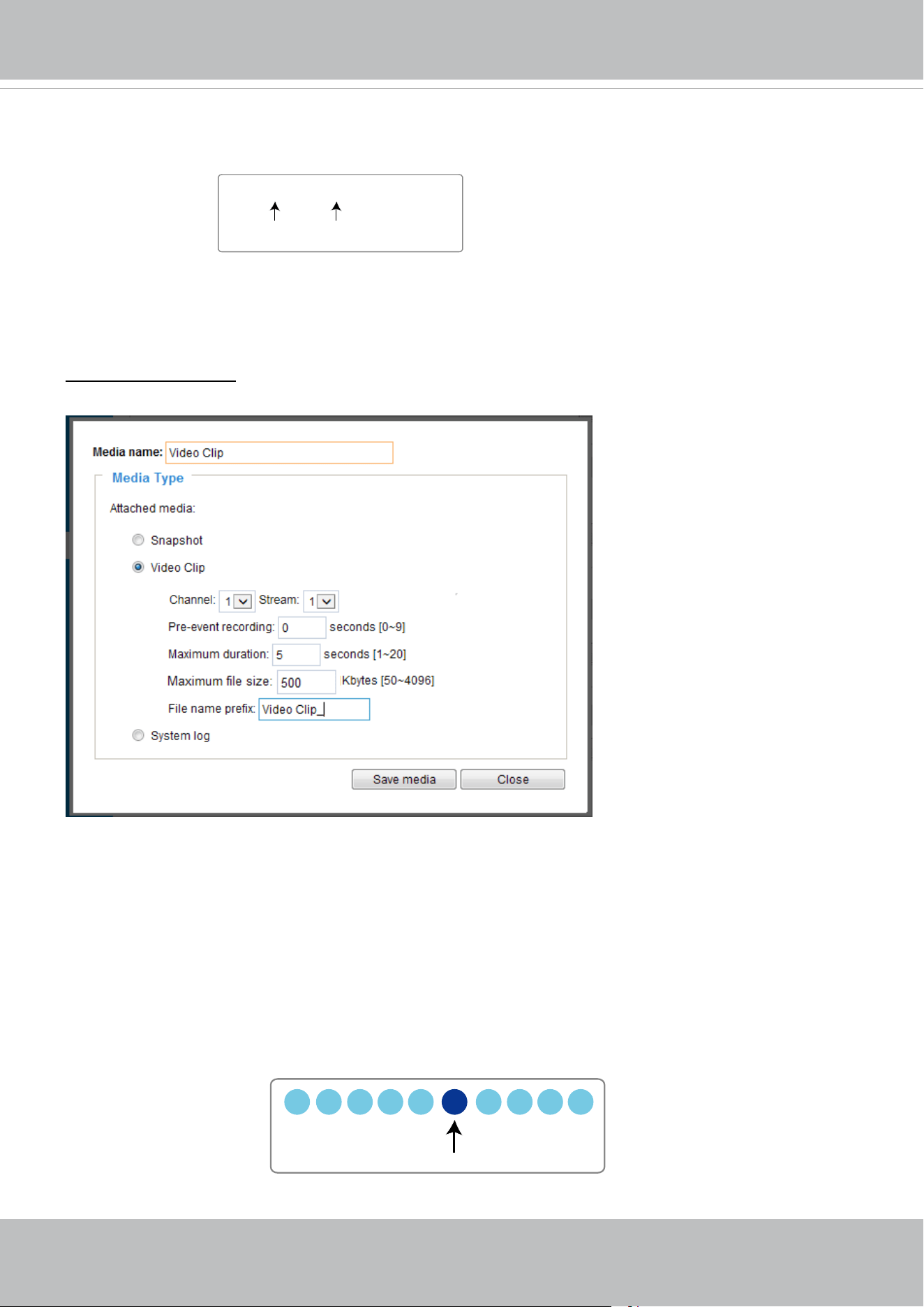
VIVOTEK
User's Manual - 151
■ Add date and time sux to the le name
Select this option to add a date/time sux to the le name.
For example:
Click Save media to enable the settings.
Note that after you set up the rst media server, a new column for media server will automatically display
on the Media list. If you wish to add more media options, click Add media.
Media type -
Video clip
Select to send video clips when a trigger is activated.
■ Media name: Enter a name for the media setting.
■ Source: Select a video stream as the source of video clip.
■ Pre-event recording
The Network Camera has a buffer to temporarily hold data up to a certain limit. Enter a number to
decide the duration of recording before a trigger is activated. Up to 9 seconds can be set.
■ Maximum duration
Specify the maximum recording duration in seconds. The duration can be up to 10 seconds.
For example, if pre-event recording is set to five seconds and the maximum duration is set to ten
seconds, the Network Camera continues to record for another 4 seconds after a trigger is activated.
Snapshot_20190513_100341
Date and time suffix
The format is: YYYYMMDD_HHMMSS
File name prefix
1 sec. 2 sec. 3 sec. 4 sec. 5 sec. 6 sec. 7 sec. 8 sec. 9 sec. 10 sec.
Trigger Activation
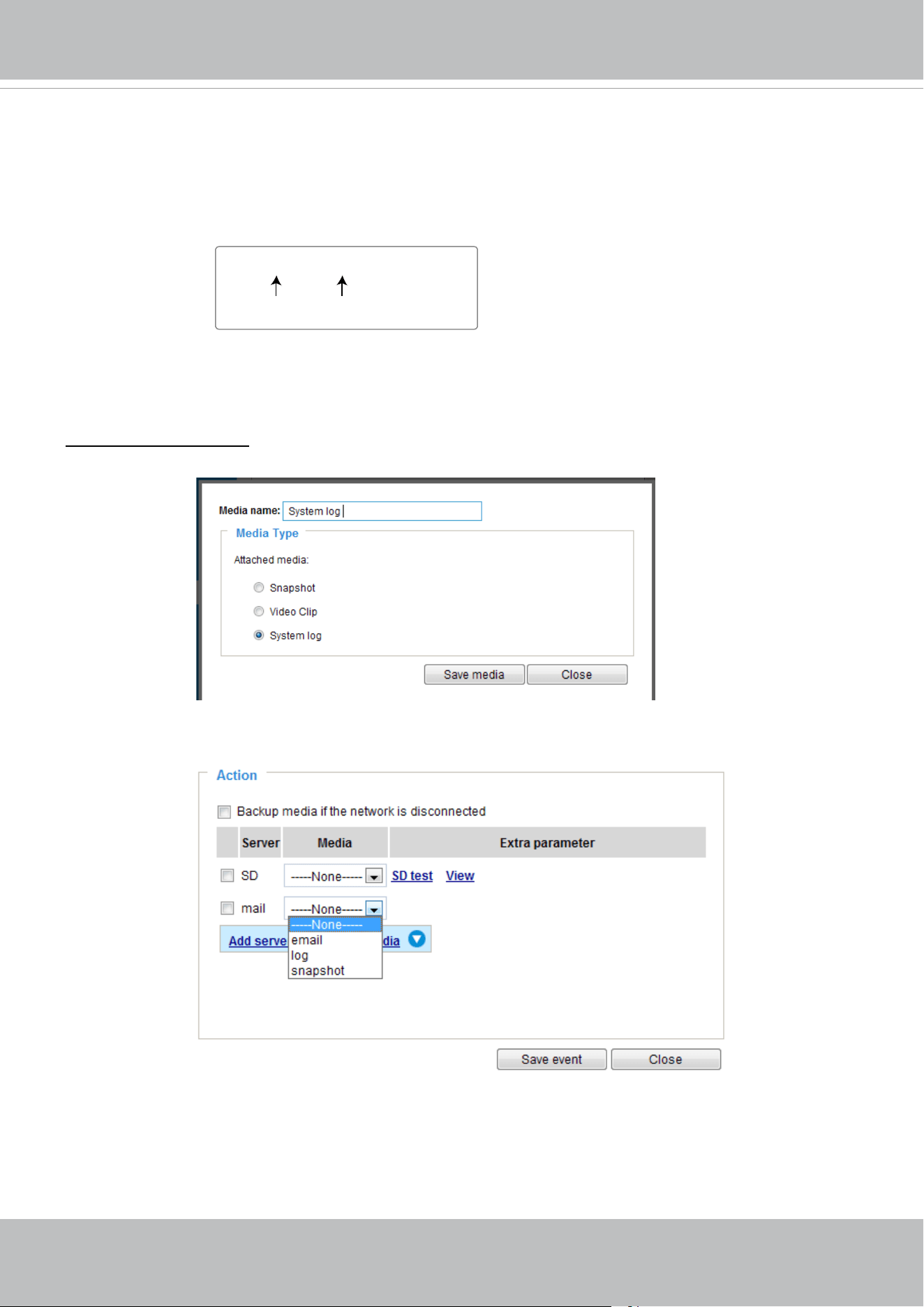
VIVOTEK
152 - User's Manual
■ Maximum le size
Specify the maximum le size allowed. Some users may need to stitch the video clips together when
searching and packing up forensic evidence.
■ File name prex
Enter the text that will be appended to the front of the le name.
For example:
Click Save media to enable the settings.
Media type - System log
Select to send a system log when a trigger is activated.
Click Save media to enable the settings, then click Close to exit the page.
Video_20190513_100341
Date and time suffix
The format is: YYYYMMDD_HHMMSS
File name prefix
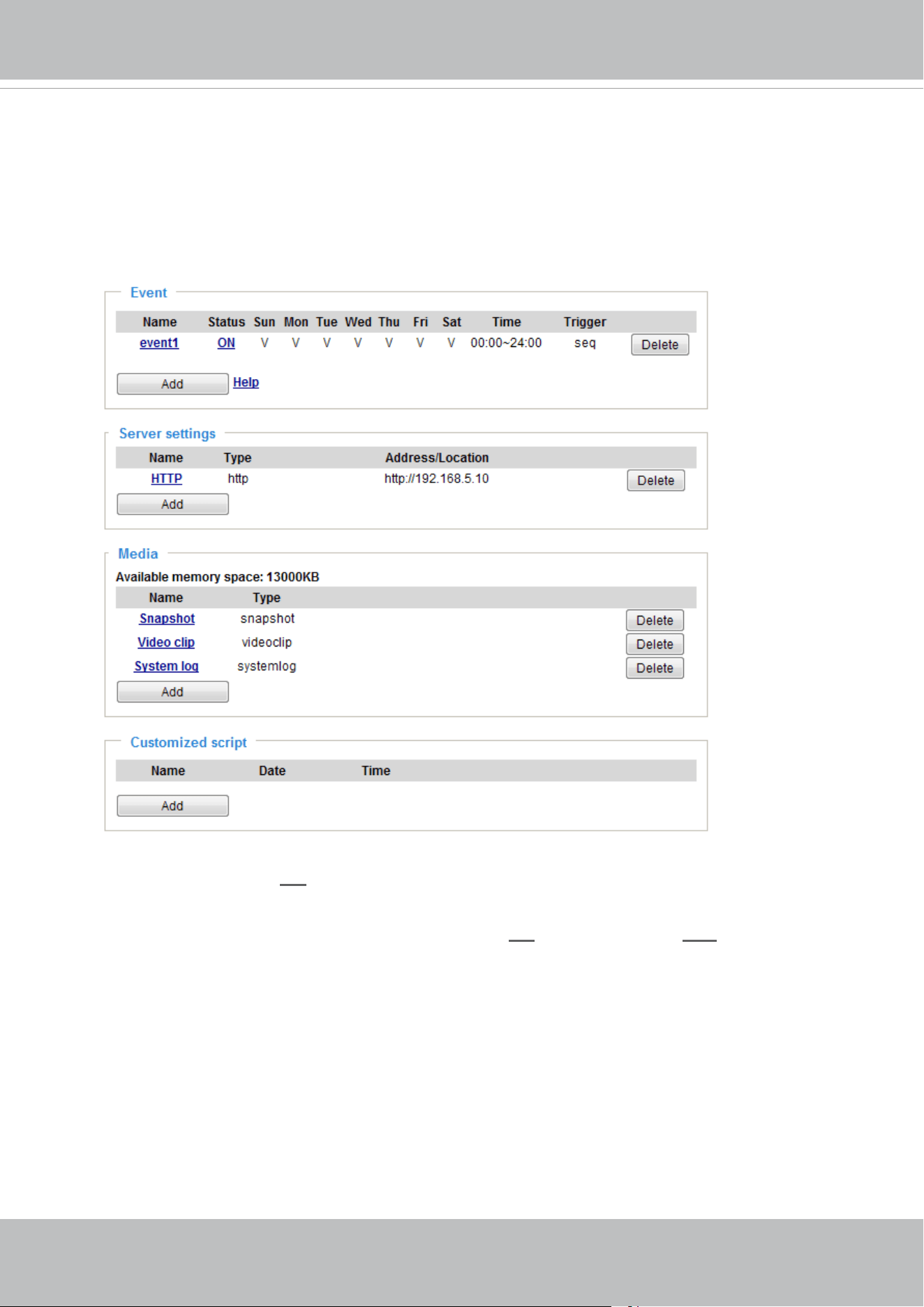
VIVOTEK
User's Manual - 153
In the Event settings column, the Servers and Medias you congured will be listed; please make sure the
Event -> Status is indicated as ON, in order to enable the event triggering action.
When completed, click the Save event button to enable the settings and click Close to exit Event
Settings page. The new Event / Server settings / Media will appear in the event drop-down list on the
Event setting page.
Please see the example of the Event setting page below:
When the Event Status is ON, the event configuration above is triggered by motion detection, the
Network Camera will automatically send snapshots via e-mail.
If you want to stop the event trigger, you can click on the
ON button to turn it to OFF status or click the
Delete button to remove the event setting.
To remove a server setting from the list, select a server name from the drop-down list and click Delete.
Note that you can only delete a server setting when it is not applied in an existing event setting.
To remove a media setting from the list, select a media name from the drop-down list and click Delete.
Note that you can only delete a media setting when it is not applied in an existing event setting.
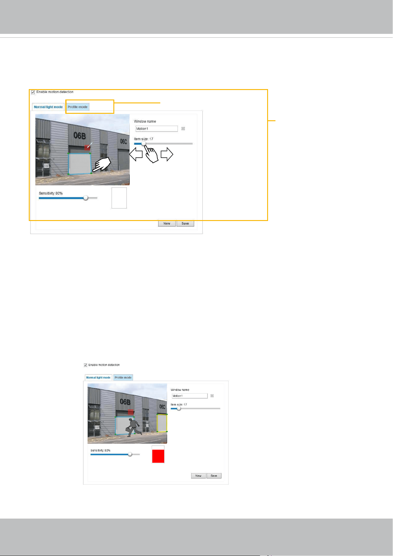
VIVOTEK
154 - User's Manual
Motion Detection Setting 2:
For special situations
Motion Detection Setting 1:
For normal situations
Applications > Motion detection
This section explains how to congure the Network Camera to enable motion detection. A total
of 5 motion detection windows can be congured.
Follow the steps below to enable motion detection:
1. Click New to add a new motion detection window.
2. In the Window Name text box, enter a name for the motion detection window.
■ Use 4 mouse clicks to designate a detection window. You can change the window shape by dragging
the corner marks to a preferred location.
■ Drag the item size tab to change the minimum size of item to trigger an alarm. An item size box will
appear in the center of screen for your reference (in semi-transparent red). An intruding object must
be larger than the Item size to trigger an alarm. Change the item size according to the live view.
■ To delete a window, click the X mark on the right of the window name.
3. Dene the sensitivity to moving objects by moving the Sensitivity slide bar. Note that a high sensitivity
is prone to produce false alarms such as the fast changes of light (such as day/night mode switch,
turning lights on/o). A movement must persist longer than 0.3 second for the motion to be detected.
4. Click Save to enable the settings.
5. Select Enable motion detection to enable this function.
For example:
The Percentage Indicator will rise or fall depending on the variation between sequential images. When
motions are detected by the Network Camera and are considered to exceed the preset threshold, the red
bar rises. Meanwhile, the motion detection window will be outlined in red.
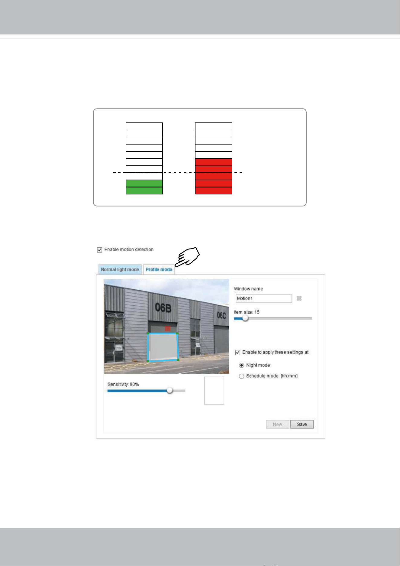
VIVOTEK
User's Manual - 155
A green bar indicates that even though motions have been detected, the event has not been
triggered because the image variations still fall under the preset threshold.
If you want to congure other motion detection settings for day/night/schedule mode (e.g., for a
dierent lighting condition), please click Prole to open the Motion Detection Prole Settings page
as shown below. Another three motion detection windows can be congured on this page.
Larger than the
min. item size
Photos or videos can be captured instantly and congured to be sent to a remote server (via an
Email or FTP server). For more information on how to congure an event setting, please refer to
Event settings on page 137.
Please follow the steps beolw to set up a prole:
1. Create a new motion detection window.
2. Click the Prole mode tab.
3. Select the applicable Schedule mode. Please manually enter a time range.
4. Click Save to enable the settings and click Close to exit the page.
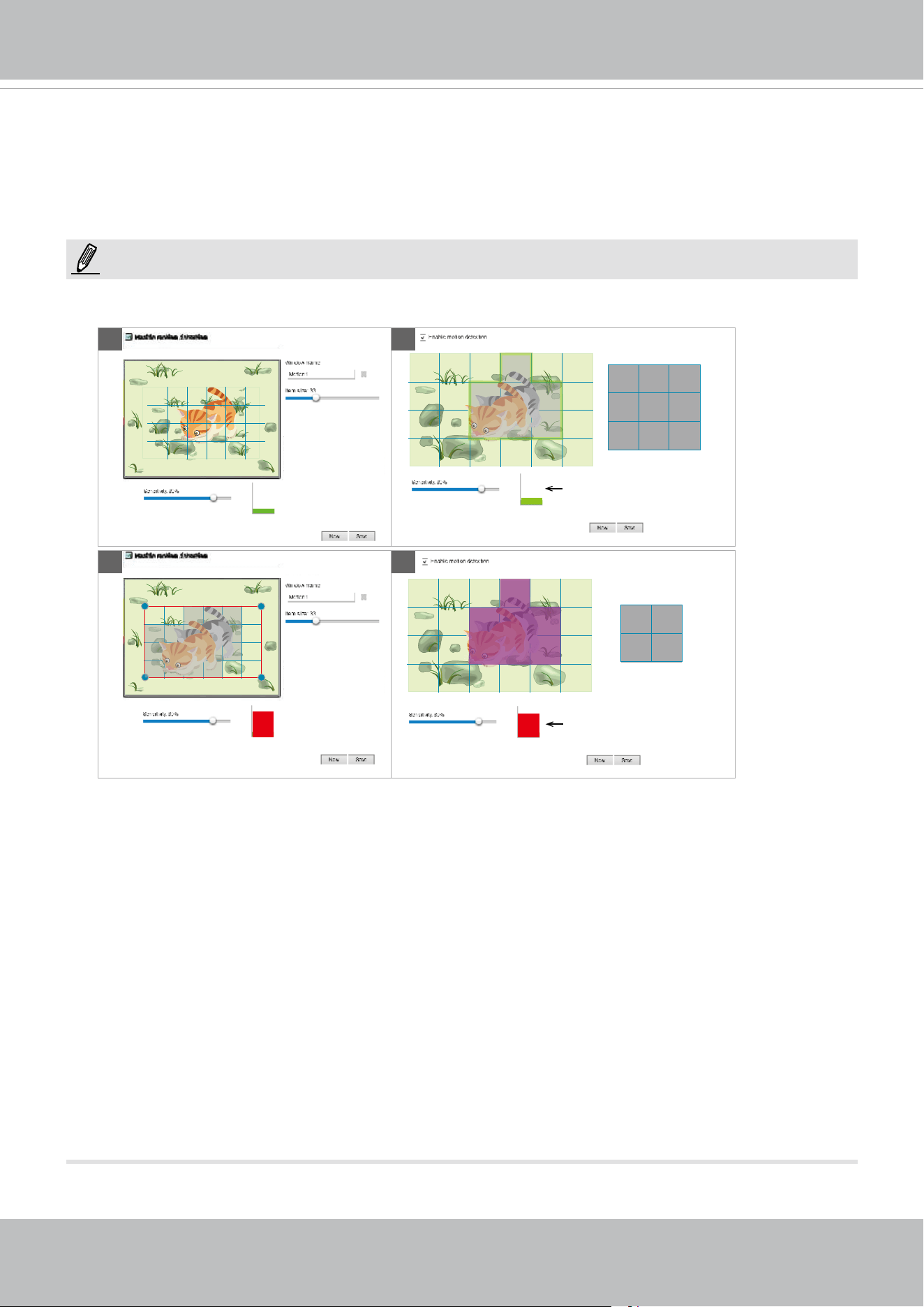
VIVOTEK
156 - User's Manual
This motion detection window will also be displayed on the Event Settings page. You can go to Event
> Event settings > Trigger to select it as a trigger source. Please refer to page 137 for detailed
information.
► How does motion detection work?
There are two motion detection parameters: Sensitivity and Min. Item Size. As illustrated above, frame
A and frame B are two sequential images. Pixel dierences between the two frames are detected and
highlighted in gray in which the sensitivity setting will take eect. Sensitivity is a value that expresses
the sensitivity to moving objects. A higher sensitivity setting allows camera to detect slight movements
while a lower sensitivity setting will neglect them.
The minimum item size is a threshold value that determines how many “alerted pixels” can trigger an
event. When the size of an intruding object is larger than the minimum size, and its movement persist
for 0.3 second, the motion is judged to exceed the dened threshold; and the motion window will be
outlined in red. With a large minimum item size, the size of moving object in frame C is considered as
smaller than the minimum item size, no motion alarm is triggered. With a smaller minimum item size,
the same moving object in frame D triggers the alarm.
For applications that require a high level of security management, it is suggested to use higher
sensitivity settings. However, a higher sensitivity level can also produce false alarms due to fast light
changes when switching between the day and night modes, AE switch, turning the light on or o, etc.
A
B D
C
Min. item size
Alerted pixels < Min. item size
Alerted pixels > Min. item size
Min. item size
NOTE:
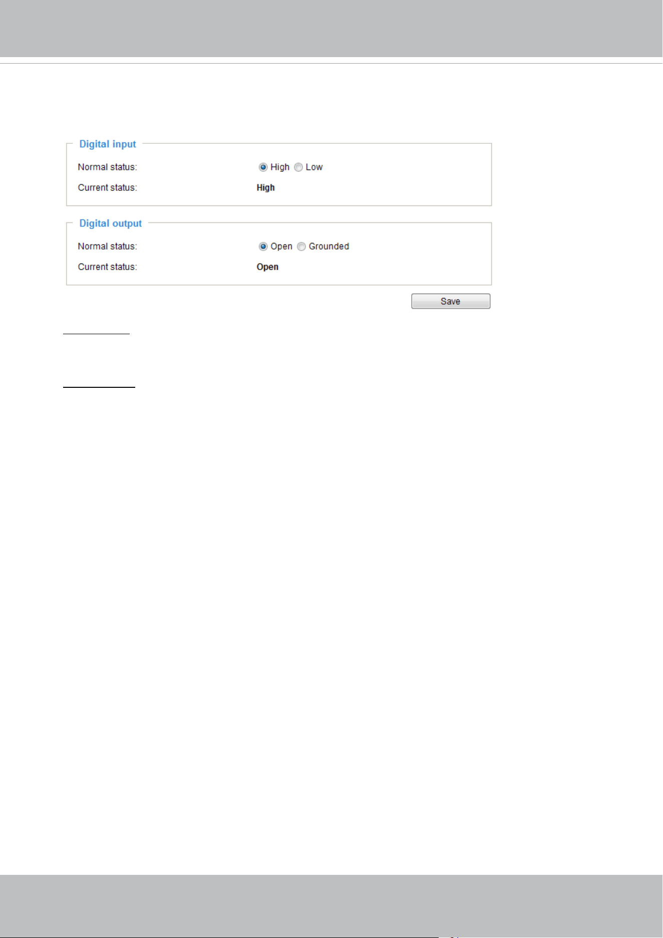
VIVOTEK
User's Manual - 157
Applications > DI and DO
Digital input: Select High or Low as the Normal status for the digital input connection. Connect
the digital input pin of the Network Camera to an external device to detect the current connection
status.
Digital output: Select Grounded or Open to dene the normal status for the digital output. Connect
the digital output pin of the Network Camera to an external device to determine the current status.
Set up the event source as DI on Event > Event settings > Trigger. Please refer to page 138 for
detailed information.
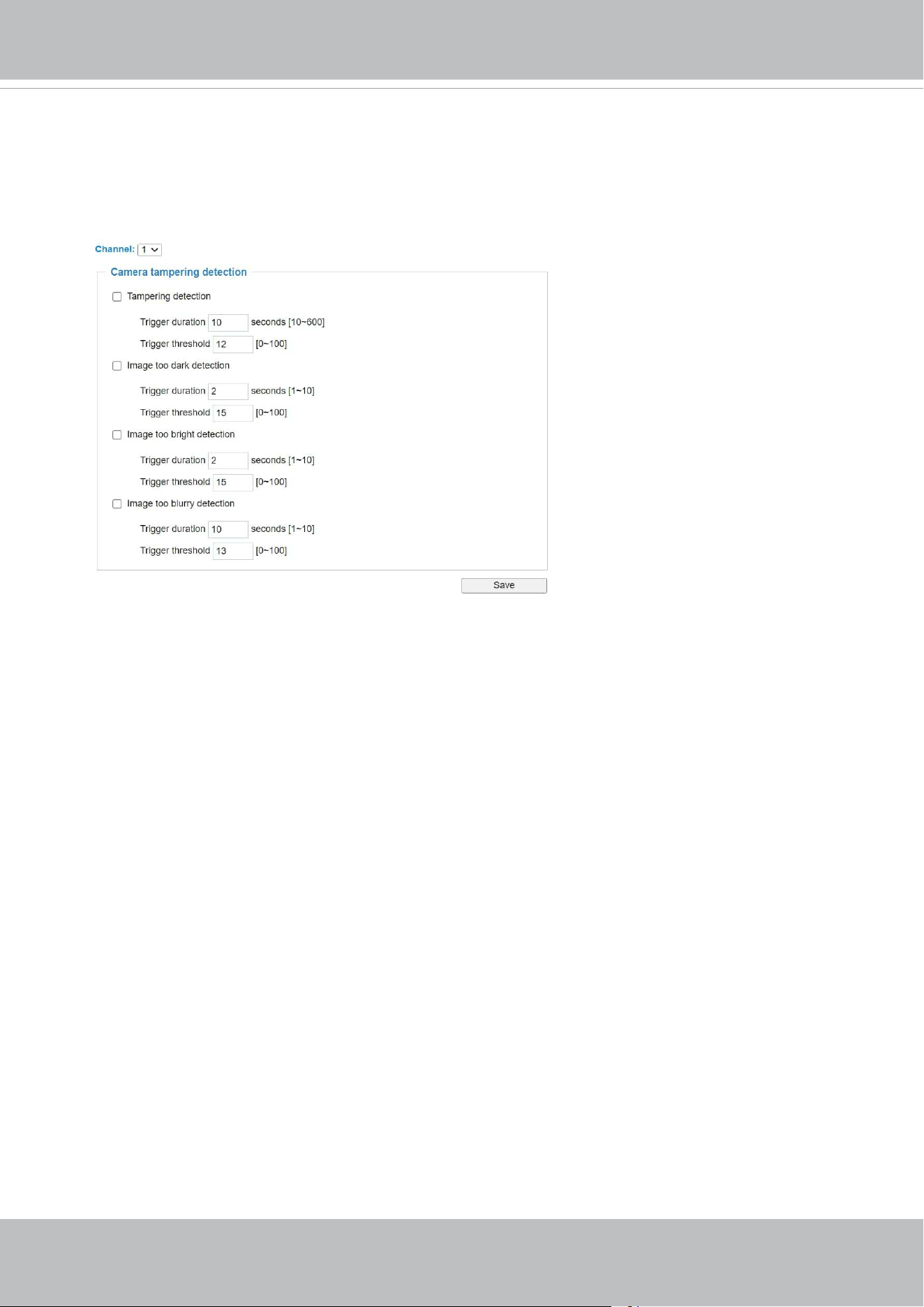
VIVOTEK
158 - User's Manual
Applications > Tampering detection
This section explains how to set up camera tamper detection. With tamper detection, the
camera is capable of detecting incidents such as redirection, blocking or defocusing, or
even spray paint.
Please follow the steps below to set up the camera tamper detection function:
1. Click to select the checkbox before tampering conditions: Tampering detection, Image
too dark, Image too bright, and Image too blurry. Enter the tamper trigger duration. (10
sec. ~ 10 min.). The duration species the set of time before the tampering is considered
as a real alarm. This helps avoid false alarms by short-lived changes.
The tamper alarm will be triggered only when the tampering factor (the difference
between current frame and pre-saved background) exceeds the trigger threshold.
Conditions such as image too dark, too bright, or too blurry (defocused) can also be
configured as tampering conditions. The Trigger threshold determines how sensitive
your is tamper detection setting. Lower the threshold number, easier to trigger.
Too bright: shining a flash light. The average lighting level of the scene is taken into
consideration.
Too dark: covering the objective or spraying paint.
Too blurry: blurry scene can be the result of strong interference on the device, such as
EMI interference.
2. You can configure Tampering Detection as a trigger element to the proactive event
congurations in Event -> Event settings -> Trigger. For example, when the camera is
tampered with, camera can be congured to send the pre- and post-event video clips to
a networked storage device. Please refer to page 137 for detailed information.
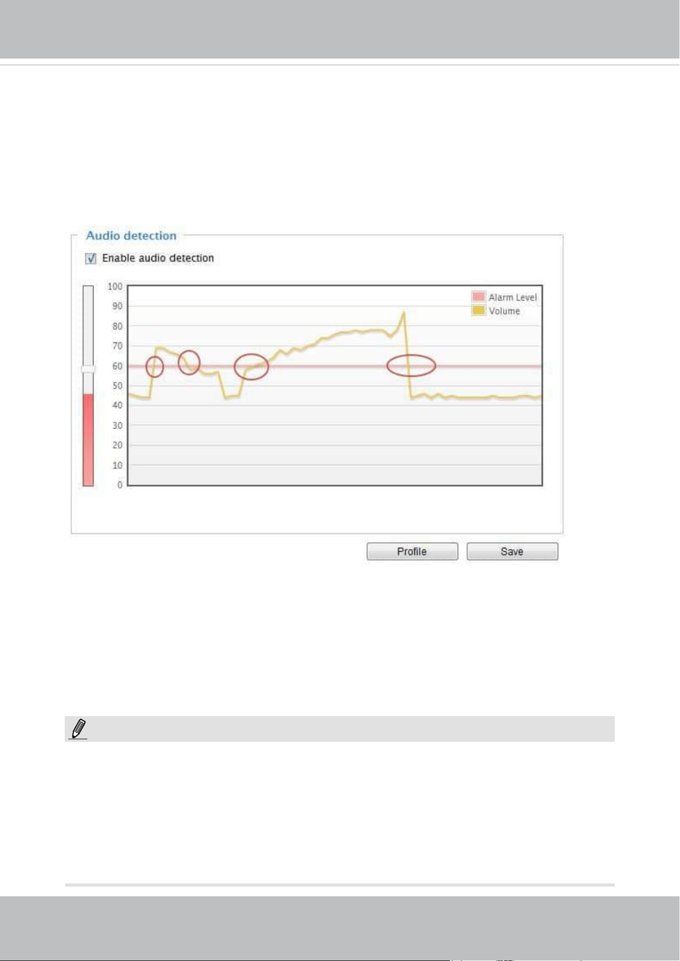
VIVOTEK
User's Manual - 159
Applications > Audio detection
Audio detection, along with video motion detection, is applicable in the following scenarios:
1. Detection of activities not covered by camera view, e.g., a loud input by gun shots or breaking a
door/window.
2. A usually noisy environment, such as a factory, suddenly becomes quiet due to a breakdown of
machines.
3. A PTZ camera can be directed to turn to a preset point by the occurrence of audio events.
4. Dark environments where video motion detection may not function well.
The red circles indicate where the audio alarms can be triggered when breaching or falling below
the preset threshold.
How to congure Audio detection:
1. Once the Audio detection window is opened, the current sound input will be interactively
indicated by a uctuating yellow wave diagram.
2. Use a mouse click to drag the Alarm level tab to a preferred location on the slide bar.
3. Select the “Enable audio detection“ checkbox and click Save to enable the feature.
1. Note that the volume numbers (0~100) on the side of wave diagram does not represent decibel
(dB). Sound intensity level has already been mapped to preset values. You can, however, use
the real-world inputs at your installation site that are shown on the wave diagram to congure
an alarm level.
2. To configure this feature, you must not mute the audio in Configuration > Media > Audio.
The default of the camera can be muted due to the lack of an internal microphone. An external
microphone is provided by users.
NOTE:
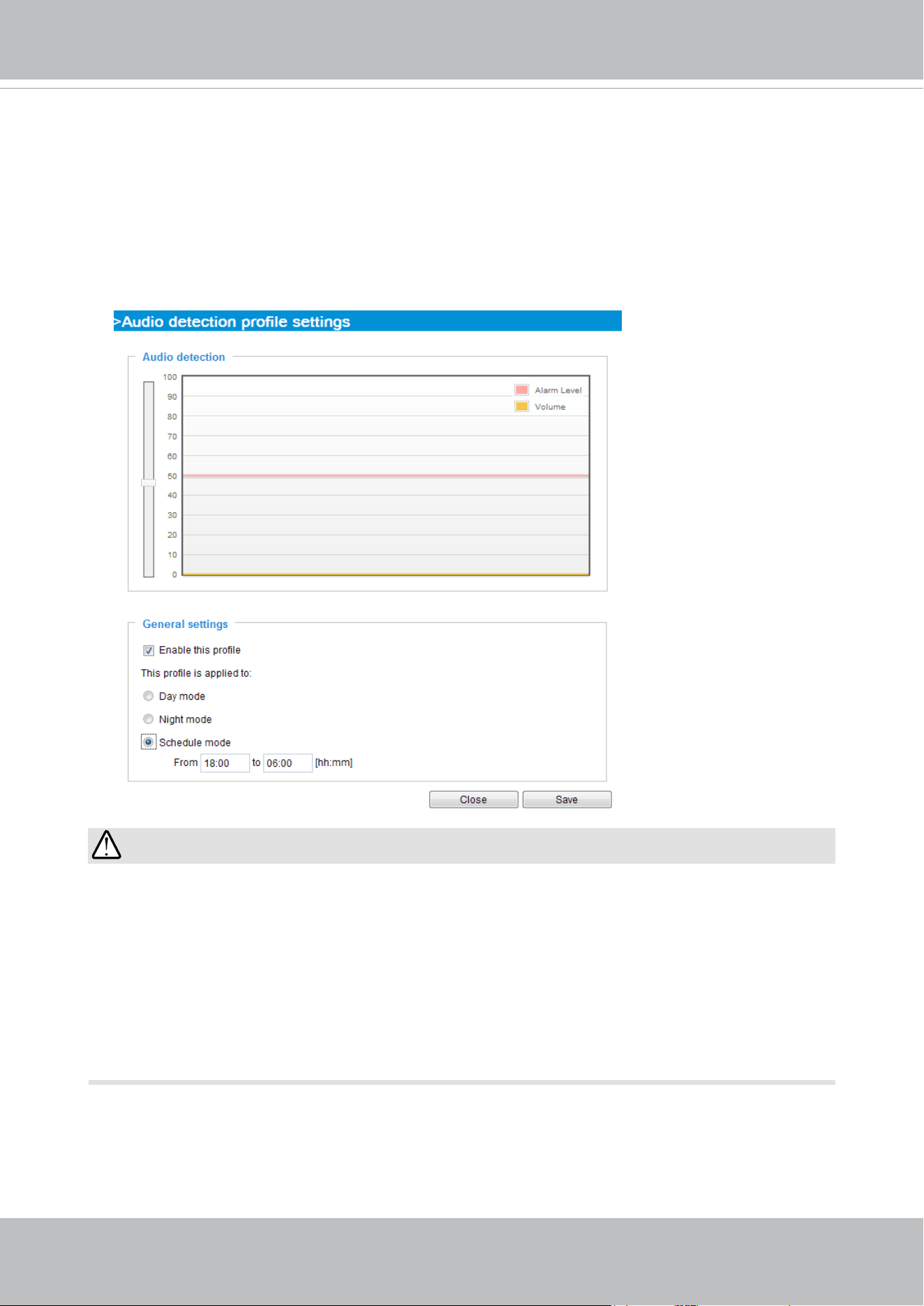
VIVOTEK
160 - User's Manual
IMPORTANT:
• If the Alarm level and the received volume are set within a range of 20% on the wave
diagram, frequent alarms will be triggered. It is recommended to set the Alarm level
farther apart from the detected sound level.
• To configure and enable this feature, you
must not
configure video stream #1 into
Motion JPEG. If an external microphone input is connected and recording of audio
stream is preferred, audio stream is transmitted between camera and viewer/recording
station along with stream #1.
• Refer to page 94 for Audio settings, and page 86 for video streaming settings.
You can use the Prole window to congure a dierent Audio detection setting. For example, a
place can be noisy in the day time and become very quiet in the night.
1. Click on the Enable this prole checkbox. Once the Audio detection window is opened, the
current sound input will be interactively indicated by a uctuating yellow wave diagram.
2. Use a mouse click to drag the Alarm level tab to a preferred location on the slide bar.
3. Select the Day, Night, or Schedule mode check circles. You may also manually congure a
period of time during which this prole will take eect.
4. Click Save and then click Close to complete your conguration.
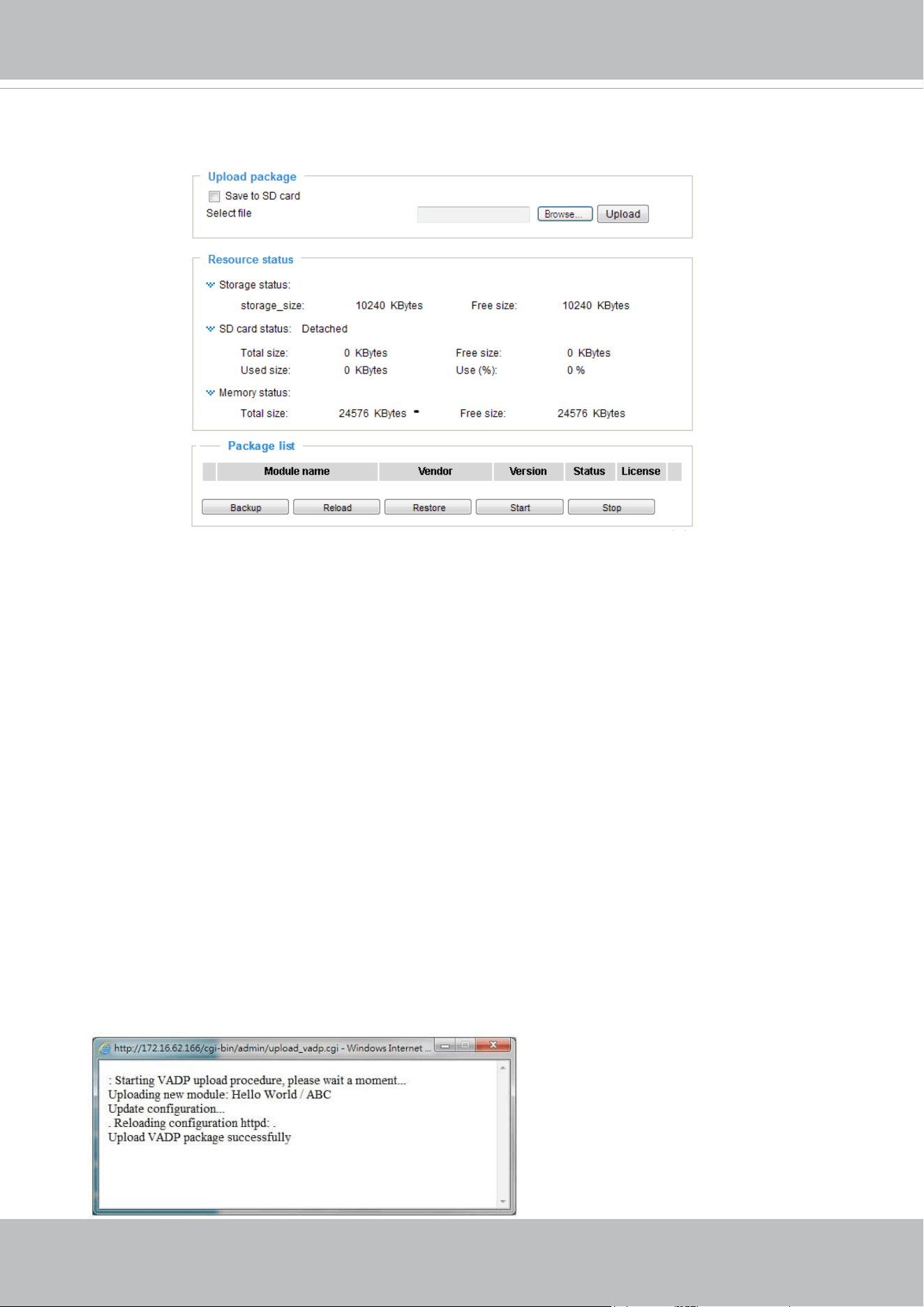
VIVOTEK
User's Manual - 161
Applications > Package management - a.k.a., VADP (VIVOTEK
Application Development Platform)
Users can store and execute VIVOTEK's or 3rd-party software modules onto the camera's
flash memory or SD card. These software modules can apply in video analysis for
intelligent video applications such as license plate recognition, object counting, or as an
agent for edge recording, etc.
• Once the software package is successfully uploaded, the module conguration (vadp.
xml) information is displayed. When uploading a module, the camera will examine
whether the module fits the predefined VADP requirements. Please contact our
technical support or the vendor of your 3rd-party module for the parameters contained
within.
• Users can also run VIVOTEK's VADP packages as a means to access updated
functionality instead of replacing the entire rmware.
• Note that for some cameras the flash is too small to hold VADP packages. These
cameras will have its "Save to SD card" checkbox selected and grayed-out for all time.
• The le system of SD card (FAT32) does not support soft (symbolic) link. It will return
failure if your module tries to create soft links on SD card.
To utilize a software module, acquire the software package and click Browse and Upload
buttons. The screen message for a successful upload is shown below:
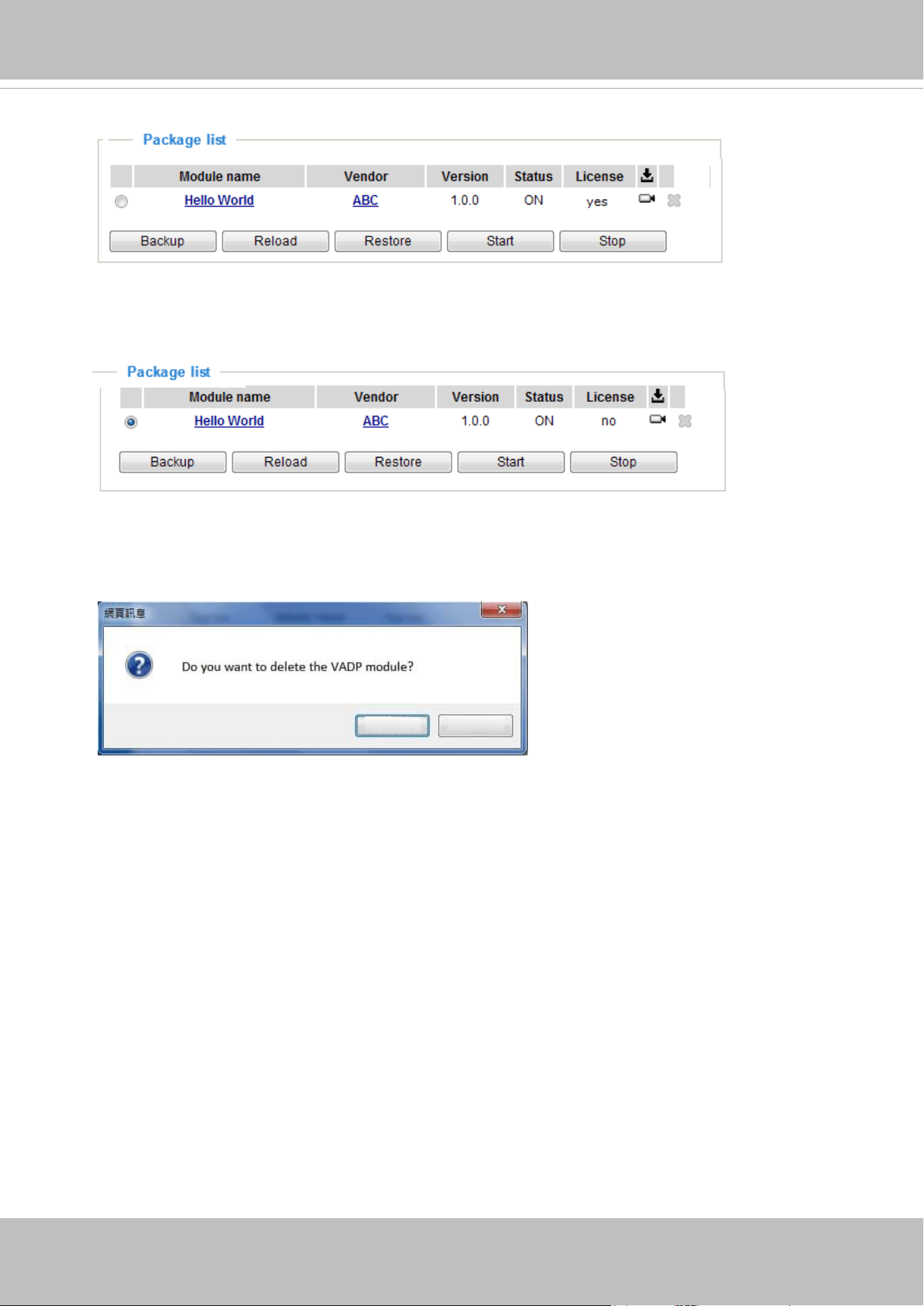
VIVOTEK
162 - User's Manual
To start a module, select the checkcircle in front, and click the Start button.
If you should need to remove a module, select the checkcircle in front and then click the
Stop button. By then the module status will become OFF, and the X button will appear at
the end of the row. Click on the X button to remove an existing module.
When prompted by a conrm message, Click Yes to proceed.
Yes
No
Note that the actual memory consumed while operating the module will be indicated on the
Memory status eld. This helps determine whether a running module has consumed too
much of system resources.
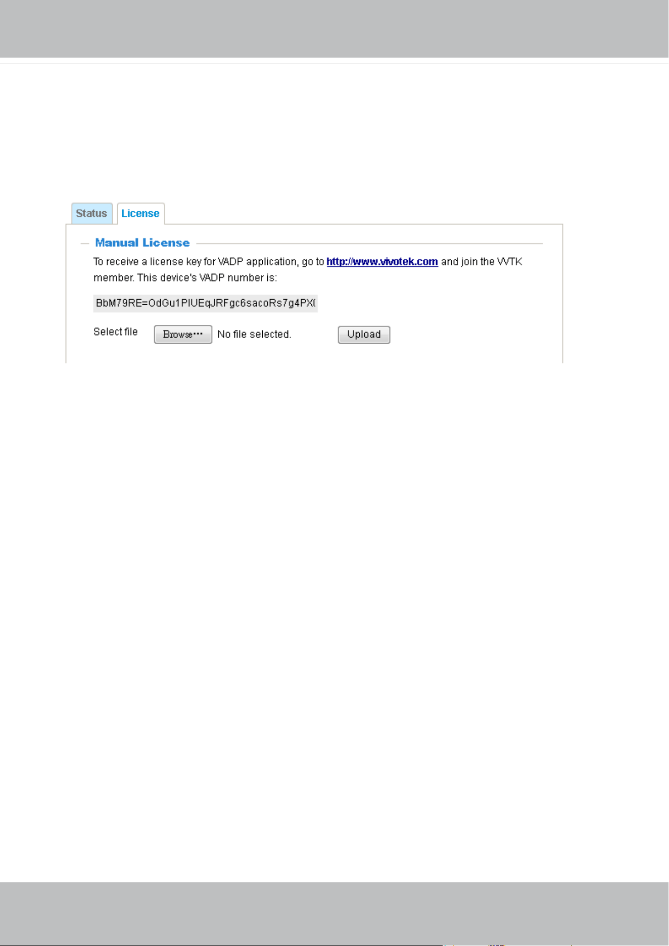
VIVOTEK
User's Manual - 163
On the License page, register and activate the license for using VIVOTEK's VADP
modules. You should acquire the license key elsewhere, and manually upload to the
network camera.
Follow the onscreen instruction on VIVOTEK's website for the registration procedure.
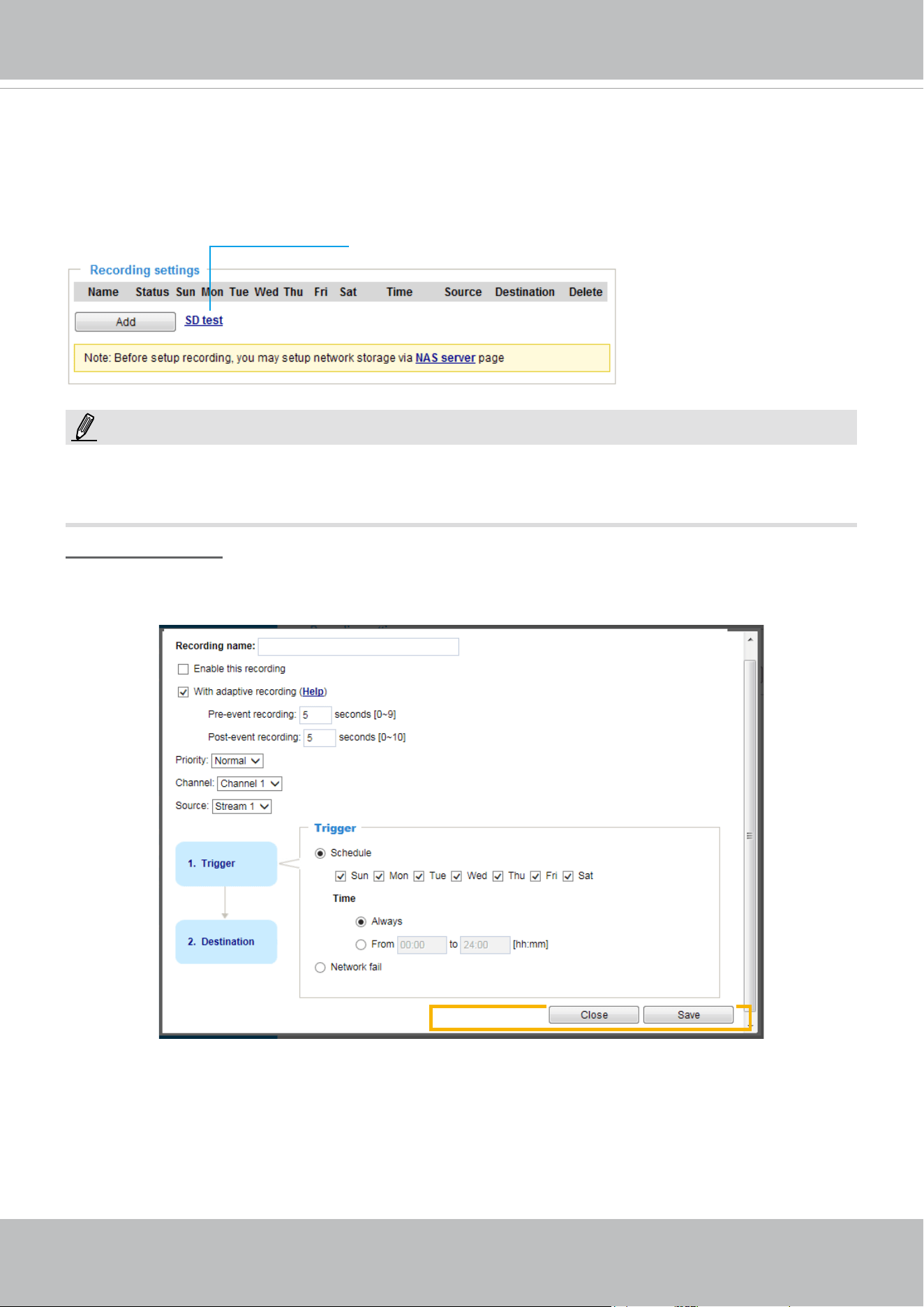
VIVOTEK
164 - User's Manual
Recording > Recording settings
This section explains how to congure the recording settings for the Network Camera.
Recording Settings
► Please remember to format your SD card via the camera’s web console (in the Local storage .
SD card management page) when using it for the first time. Please refer to page 169 for detailed
information.
Insert your SD card and click here to test
Recording Settings
Click Add to open the recording setting window. On this page, you can dene the adaptive recording,
recording source, recording schedule, and recording capacity. A total of 2 recording settings can be
congured.
■ Recording name: Enter a name for the recording setting.
■ Enable this recording: Select this option to enable video recording.
■ With adaptive recording:
Select this option will activate the frame rate control according to alarm trigger.
The frame control means that when there is a triggered alarm, the frame rate will raise up to the
value you’ve congured on the Video quality page. Please refer to page 87 for more information.
NOTE:
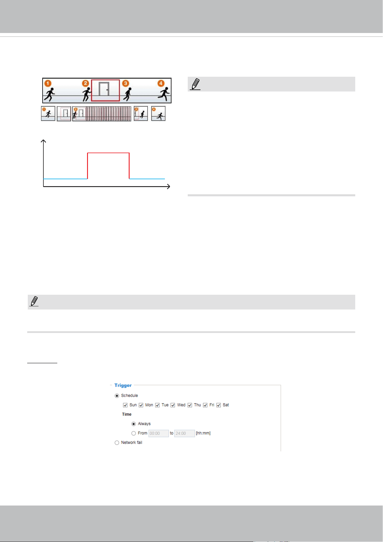
VIVOTEK
User's Manual - 165
The alarm trigger includes: motion detection and DI detection. Please refer to Event Settings on page 137.
■ Pre-event recording and post-event recording
The Network Camera has a buer that temporarily holds data for a period of time. Therefore, when an
event occurs, the camera can restrieve image frames taken several seconds ago. Enter a number to
dene the duration of recording before and after a trigger is activated.
■ Priority: Select the relative importance of this recording (High, Normal, or Low). Recording with a higher
priority setting will be executed rst.
■ Source (Channel/Stream): Select a video stream as the recording source.
► To enable recording notication please congure Event settings rst . Please refer to page 137.
If you enable adaptive recording on a camera, only when an event is triggered on Camera A will the
server record the full frame rate streaming data; otherwise, it will only request the I frame data during
normal monitoring, thus eectively saves bandwidths and storage space.
Time
Bandwidth
Bandwidth
Activity Adaptive Streaming
for Dynamic Frame Rate Control
I frame ---> Full frame rate ---> I frame
Continuous recording
► To enable adaptive recording, please make sure
you’ve set up the trigger source such as Motion
Detection, DI Device, or Manual Trigger.
► When there is no alarm trigger:
- JPEG mode: record 1 frame per second.
- H.265/H.264 mode: record the I frame only.
► When the I frame period is >1s on Video settings
page, firmware will force decrease the I frame
period to 1s when adaptive recording is enabled.
Please follow the steps below to set up the recording.
1. Trigger
Select a trigger source.
■ Schedule: The server will start to record les on the local storage or network storage (NAS).
■ Network fail: Since network fail, the server will start to record les on the local storage (SD card).
NOTE:
NOTE:
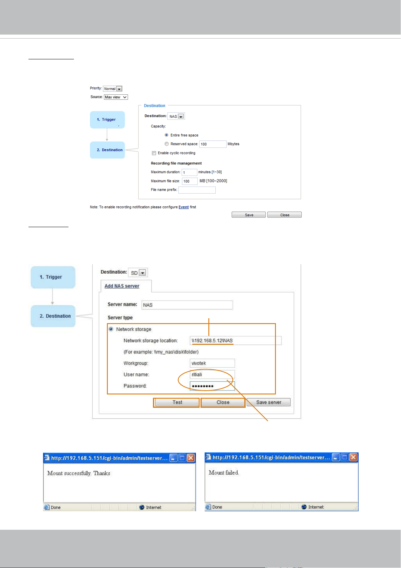
VIVOTEK
166 - User's Manual
2. Destination
You can select the SD card or network storage (NAS) for the recorded video files. If you have not
congured a NAS server, see details in the following.
NAS server
Click Add NAS server to open the server setting window and follow the steps below to congure:
1. Fill in the information for your server.
For example:
2. Click Test to check the setting. The result will be shown in the pop-up window.
1
2
3
4
Network storage path
(\\server name or IP address\folder name)
User name and password for your server
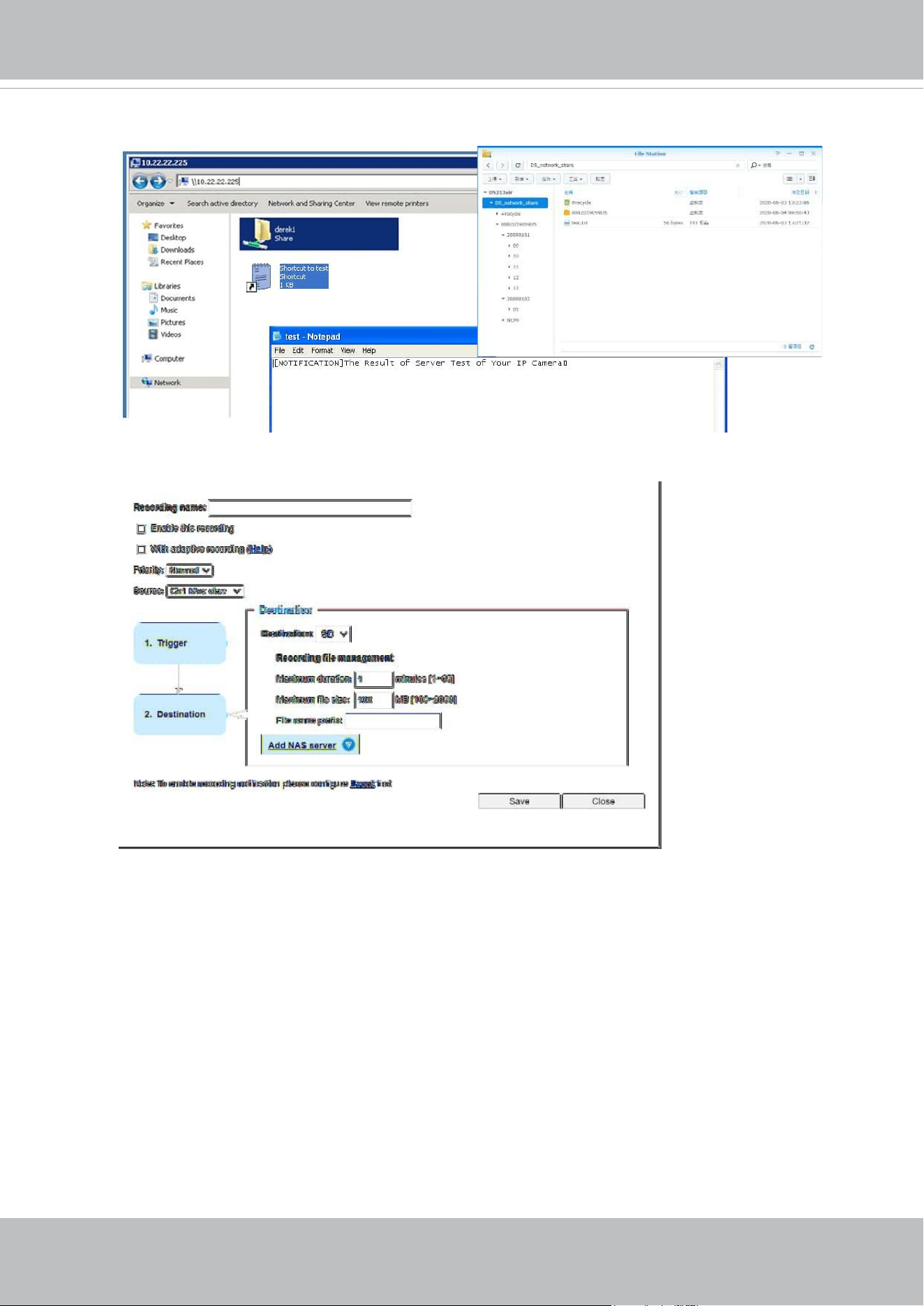
VIVOTEK
User's Manual - 167
If successful, you will receive a test.txt le on the network storage server.
3. Enter a server name.
4. Click Save to complete the settings and click Close to exit the page.
■ Capacity: You can either choose the entire free space available or limit the reserved space. The
recording size limit must be larger than the reserved amount for cyclic recording.
■ Enable cyclic recording: If you check this item, when the maximum capacity is reached, the oldest le
will be overwritten by the latest one. The reserved amount is reserved for the transaction stage when
the storage space is about to be full and new data arrives. The minimum for the Reserved space must
be larger than 15 MegaBytes.
■ Recording file management: You can manually assign the Maximum duration and the Maximum
file size for each recording footage. You may need to stitch individual files together under some
circumstances. You may also designate a le name prex by lling in the responsive text eld.
■ File name prex: Enter the text that will be appended to the front of the le name.
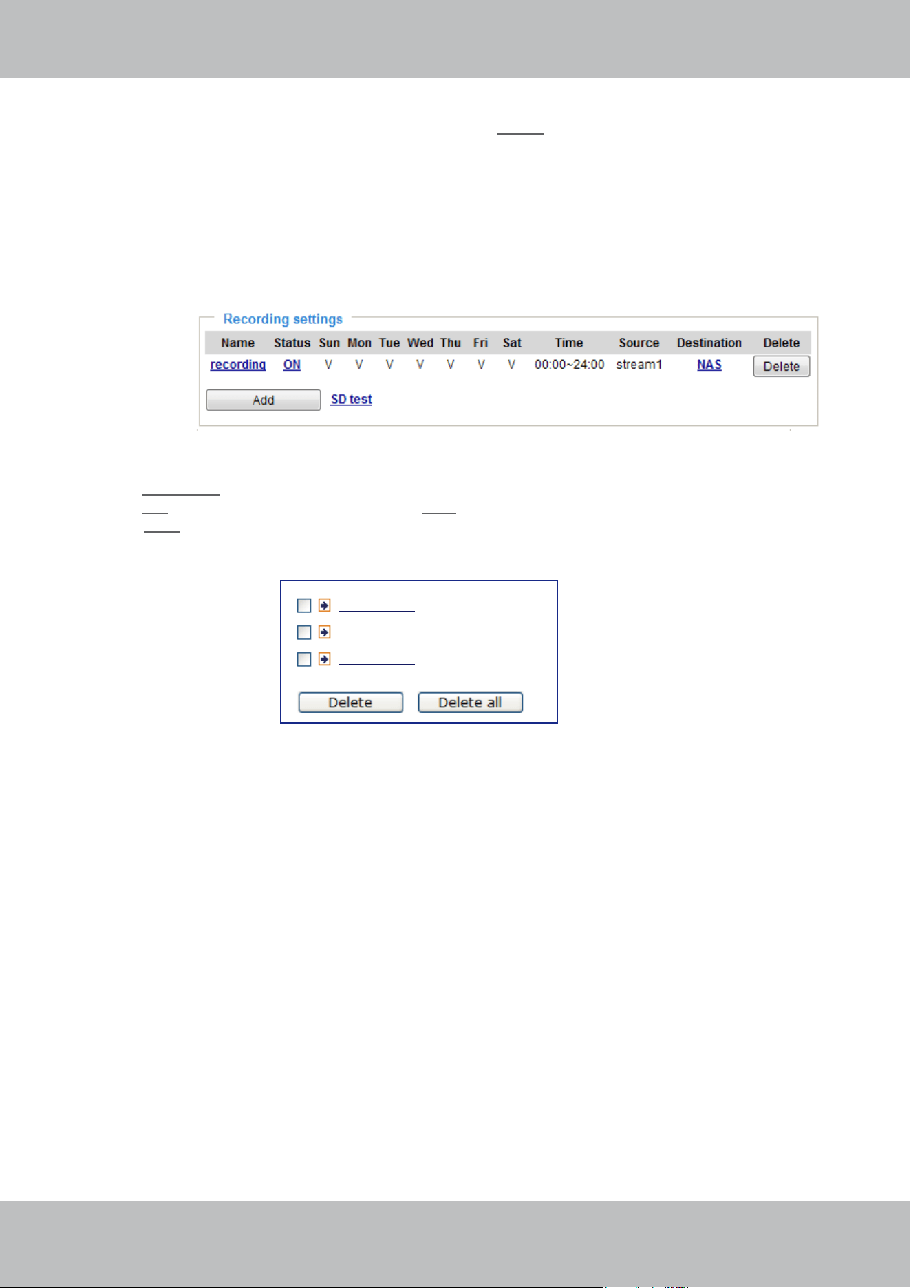
VIVOTEK
168 - User's Manual
To remove a recording setting from the list, select a recording name from the drop-down list and
click Delete.
■ Click
recording (Name): Opens the Recording Settings page to modify.
■ Click
ON (Status): The Status will become OFF and stop recording.
■ Click
NAS (Destination): Opens the le list of recordings as shown below. For more information
about folder naming rules, please refer to page 148 for details.
20190210
20190211
20190212
f you want to enable recording notication, please click
Event
to congure event triggering settings.
Please refer to Event > Event settings on page 137 for more details.
When completed, select Enable this recording. Click Save to enable the setting and click Close
to exit this page. When the system begins recording, it will send the recorded les to the network
storage. The new recording name will appear in the drop-down list on the recording page as shown
below.
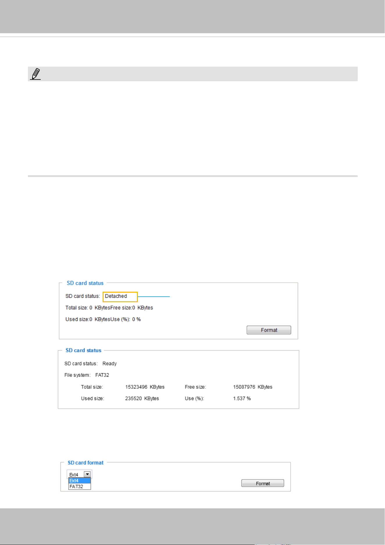
VIVOTEK
User's Manual - 169
Storage
SD card format
The Linux kernel EXT4 file system format applies to SD card larger than 32GB. However, if EXT4 is
applied, the computers running Windows will not be able to access the contents on the SD card unless
using some 3rd-party software .
This section explains how to manage the local storage on the Network Camera. Here you can
view SD card status, and implement SD card control.
SD card staus
This column shows the status and reserved space of your SD card. Please remember to format the SD
card when using for the rst time.
no SD card
NOTE:
• It is recommended to turn OFF the recording activity before you remove an SD card from the
camera.
• The lifespan of an SD card is limited. Regular replacement of the SD card can be necessary.
• Camera lesystem takes up several megabytes of memory space. The storage space cannot
be used for recording.
• Using an SD card that already contains data recorded by another device should not be used
in this camera.
• Please do not modify or change the folder names in the SD card. That may result in camera
malfunctions.
Storage > SD card management
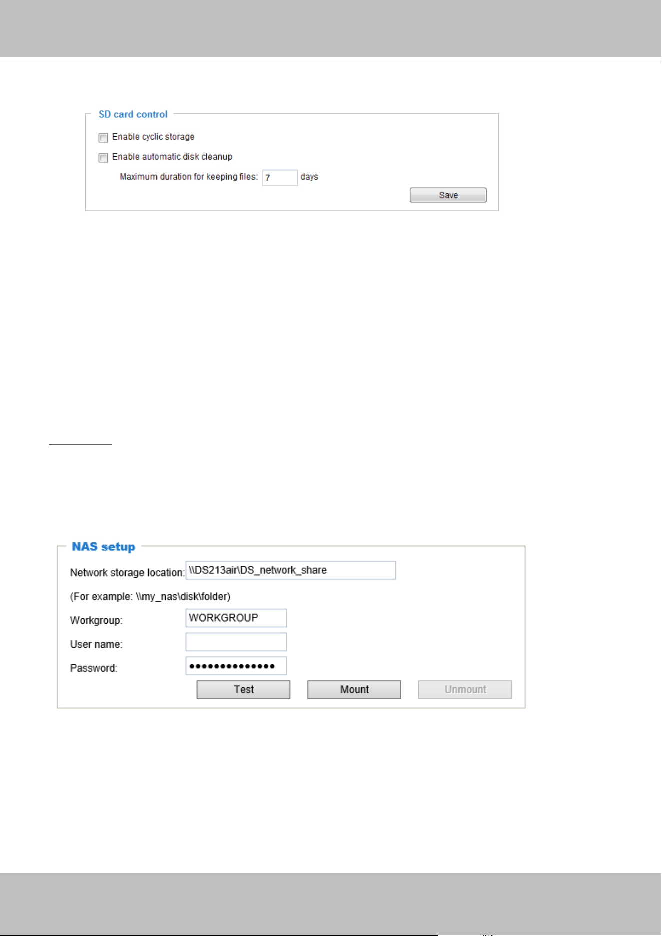
VIVOTEK
170 - User's Manual
SD card control
■ Enable cyclic storage: Check this item if you want to enable cyclic recording. When the maximum
capacity is reached, the oldest le will be overwritten by the latest one.
■ Enable automatic disk cleanup: Check this item and enter the number of days you wish to retain a le.
For example, if you enter “7 days”, the recorded les will be stored on the SD card for 7 days.
Click Save to enable your settings.
Storage > NAS management
NAS Setup
Click NAS management tab to open the server setting window and follow the steps below to set up:
1. Fill in the information for the access to the shared networked storage.
For example:
\\192.160.5.122\NAS
vivotek
rita.li
admin
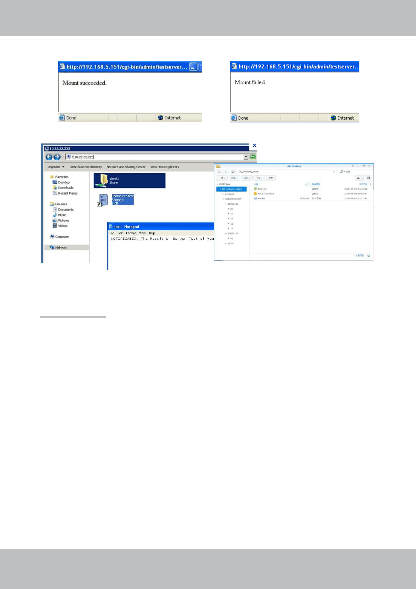
VIVOTEK
User's Manual - 171
If successful, you will receive a test.txt le on the networked storage server.
3. Click Mount to complete the settings.
2. Click Test to check the setting. The result will be shown in the pop-up window.
NAS management
■ Minimum reserved storage space: The reserved space can be used as a safe buffer
especially when the cyclic recording function is enabled, during the transaction stage when
a storage space is full and the incoming streaming data is about to overwrite the previously
saved videos.
■ Enable cyclic storage: Allows previous recordings to be overwritten by new recordings.
■ Enable automatic disk cleanup: Allows you to specify how long the recording les will be kept
on the NAS storage.
Maximum duration for keeping les: __ days: Specify the days of retention of the video les
recorded to the NAS storage.
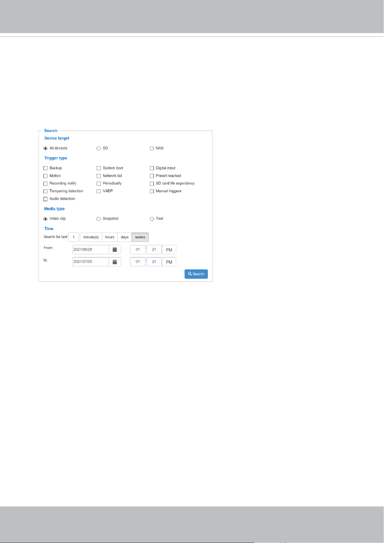
VIVOTEK
172 - User's Manual
Storage > Content management
This section explains how to manage the content of recorded videos on the Network Camera. Here
you can search and view the records and view the searched results.
Searching and Viewing the Records
This column allows the user to set up search criteria for recorded data. If you do not select any
criteria and click Search button, all recorded data will be listed in the Search Results column.
■ File attributes: Select one or more items as your search criteria.
■ Trigger time: Manually enter the time range you want to search for contents created at a specic
point in time.
Click Search and the recorded data corresponding to the search criteria will be listed in Search
Results window.
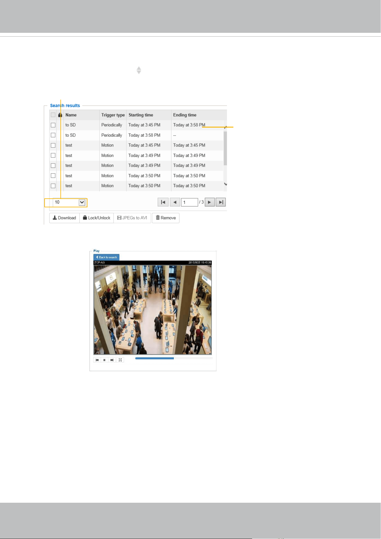
VIVOTEK
User's Manual - 173
Search Results
The following is an example of search results. There are four columns: Trigger time, Media type,
Trigger type, and Locked. Click
to sort the search results in either direction.
Numbers of entries
displayed on one page
Click to open a live view
■ Play: Click on a search result which will highlight the selected item. A Play window will appear on
top for immediate review of the selected le.
For example:
■ Download: Click on a search result to highlight the selected item in purple as shown above. Then
click the Download button and a le download window will pop up for you to save the le.
■ JPEGs to AVI: This function only applies to “JPEG“ format files such as snapshots. You can
select several snapshots from the list, then click this button. Those snapshots will be converted
into an AVI le.
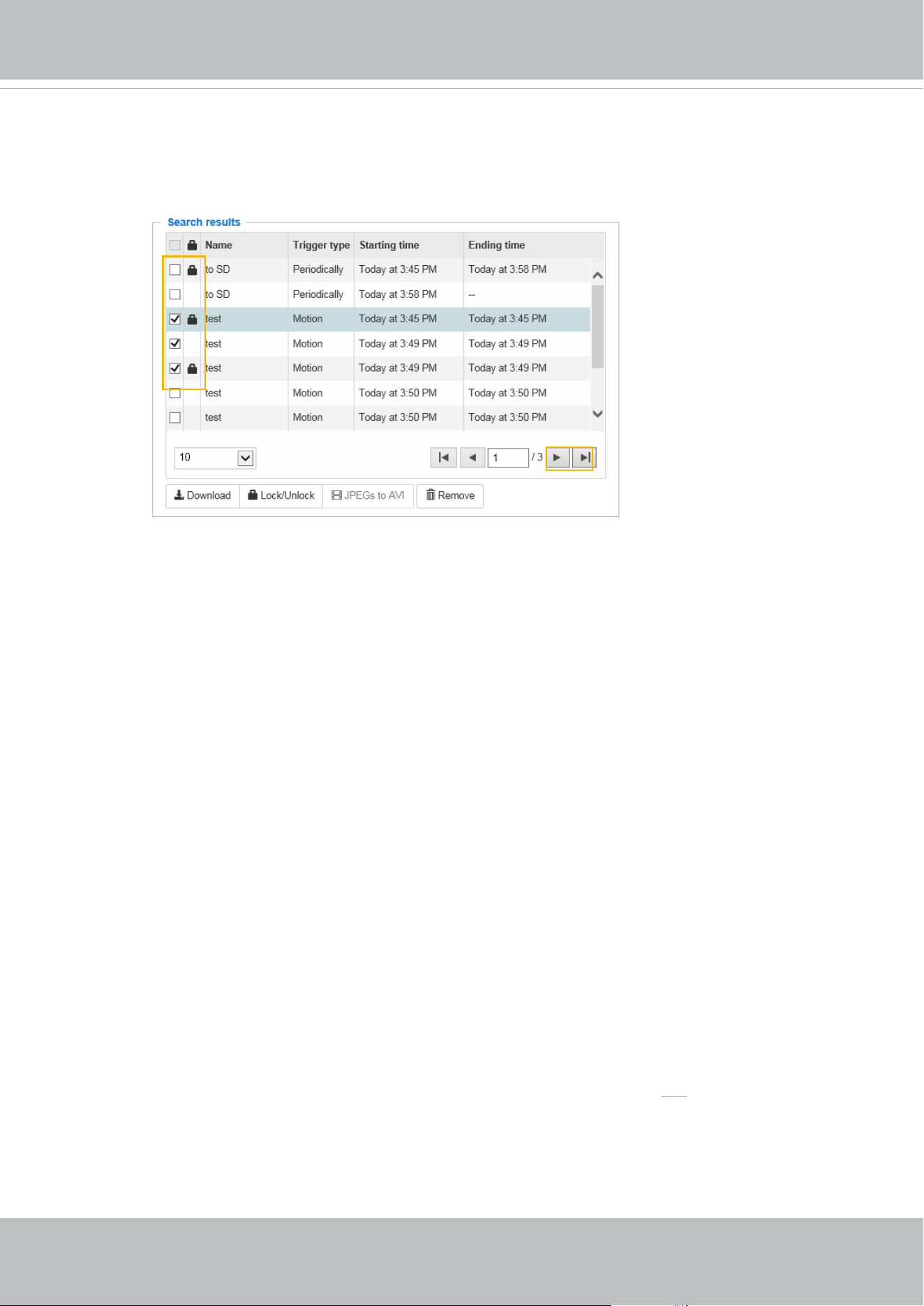
VIVOTEK
174 - User's Manual
■ Lock/Unlock: Select the checkbox in front of a desired search result, then click this button. The selected
items will become Locked, which will not be deleted during cyclic recording. You can click again to
unlock the selections.
For example:
■ Remove: Select the desired search results, then click this button to delete the les.
Click to switch
pages

VIVOTEK
User's Manual - 175
NOTE:
• Currently this model does not support URL commands.
VIVOTEK
176 - User's Manual
Technology License Notice
AMR-NB Standard
THIS PRODUCT IS LICENSED UNDER THE AMR-NB STANDARD PATENT LICENSE AGREEMENT. WITH
RESPECT TO THE USE OF THIS PRODUCT, THE FOLLOWING LICENSORS’ PATENTS MAY APPLY:
TELEFONAKIEBOLAGET ERICSSON AB: US PAT. 6192335; 6275798; 6029125; 6424938; 6058359. NOKIA
CORPORATION: US PAT. 5946651; 6199035. VOICEAGE CORPORATION: AT PAT. 0516621; BE PAT. 0516621;
CA PAT. 2010830; CH PAT. 0516621; DE PAT. 0516621; DK PAT. 0516621; ES PAT. 0516621; FR PAT. 0516621;
GB PAT. 0516621; GR PAT. 0516621; IT PAT. 0516621; LI PAT. 0516621; LU PAT. 0516621; NL PAT. 0516621;
SE PAT 0516621; US PAT 5444816; AT PAT. 819303/AT E 198805T1; AU PAT. 697256; BE PAT. 819303; BR PAT.
9604838-7; CA PAT. 2216315; CH PAT. 819303; CN PAT. ZL96193827.7; DE PAT. 819303/DE69611607T2; DK
PAT. 819303; ES PAT. 819303; EP PAT. 819303; FR PAT. 819303; GB PAT. 819303; IT PAT. 819303; JP PAT. APP.
8-529817; NL PAT. 819303; SE PAT. 819303; US PAT. 5664053. THE LIST MAY BE UPDATED FROM TIME TO
TIME BY LICENSORS AND A CURRENT VERSION OF WHICH IS AVAILABLE ON LICENSOR’S WEBSITE AT
HTTP://WWW.VOICEAGE.COM.
H.264
THIS PRODUCT IS LICENSED UNDER THE AVC PATENT PORTFOLIO LICENSE FOR THE
PERSONAL AND NON-COMMERCIAL USE OF A CONSUMER TO (i) ENCODE VIDEO IN
COMPLIANCE WITH THE AVC STANDARD ("AVC VIDEO") AND/OR (ii) DECODE AVC VIDEO
THAT WAS ENCODED BY A CONSUMER ENGAGED IN A PERSONAL AND NON-COMMERCIAL
ACTIVITY AND/OR WAS OBTAINED FROM A VIDEO PROVIDER LICENSED TO PROVIDE AVC
VIDEO. NO LICENSE IS GRANTED OR SHALL BE IMPLIED FOR ANY OTHER USE. ADDITIONAL
INFORMATION MAY BE OBTAINED FROM MPEG LA, L.L.C. SEE HTTP://WWW.MPEGLA.COM
Notices from HEVC Advance:
THIS PRODUCT IS SOLD WITH A LIMITED LICENSE AND IS AUTHORIZED TO BE USED ONLY
IN CONNECTION WITH HEVC CONTENT THAT MEETS EACH OF THE THREE FOLLOWING
QUALIFICATIONS: (1) HEVC CONTENT ONLY FOR PERSONAL USE; (2) HEVC CONTENT THAT
IS NOT OFFERED FOR SALE; AND (3) HEVC CONTENT THAT IS CREATED BY THE OWNER OF
THE PRODUCT. THIS PRODUCT MAY NOT BE USED IN CONNECTION WITH HEVC ENCODED
CONTENT CREATED BY A THIRD PARTY, WHICH THE USER HAS ORDERED OR PURCHASED
FROM A THIRD PARTY, UNLESS THE USER IS SEPARATELY GRANTED RIGHTS TO USE THE
PRODUCT WITH SUCH CONTENT BY A LICENSED SELLER OF THE CONTENT. YOUR USE OF
THIS PRODUCT IN CONNECTION WITH HEVC ENCODED CONTENT IS DEEMED ACCEPTANCE
OF THE LIMITED AUTHORITY TO USE AS NOTED ABOVE.

VIVOTEK
User's Manual - 177
Electromagnetic Compatibility (EMC)
FCC Statement
This device compiles with FCC Rules Part 15. Operation is subject to the following two conditions.
■ This device may not cause harmful interference, and
■ This device must accept any interference received, including interference that may cause undesired
operation.
This equipment has been tested and found to comply with the limits for a Class B digital device, pursuant
to Part 15 of the FCC Rules. These limits are designed to provide reasonable protection against harmful
interference in a residential installation. This equipment generates, uses and can radiate radio frequency
energy and, if not installed and used in accordance with the instructions, may cause harmful interference
to radio communications. However, there is no guarantee that interference will not occur in a partial
installation. If this equipment does cause harmful interference to radio or television reception, which
can be determined by turning the equipment off and on, the user is encouraged to try to correct the
interference by one or more of the following measures:
■ Reorient or relocate the receiving antenna.
■ Increase the separation between the equipment and receiver.
■ Connect the equipment into an outlet on a circuit different from that to which the receiver is connected.
■ Consult the dealer or an experienced radio/TV technician for help.
Shielded interface cables must be used in order to comply with emission limits.
CE Mark Warning
This is a Class B product. In a domestic environment, this product may cause radio interference, in which
case the user may be required to take adequate measures.
VCCI規制について
この装置は、クラスB情報技術装置です。この装置は、家庭環境で使用することを目的としていますが、
この装置がラジオやテレビジョン受信機に近接して使用されると、受信障害を引き起こすことがありま
す。取扱説明書に従って正しい取扱いをして下さい。 VCCI-B
Liability
VIVOTEK Inc. cannot be held responsible for any technical or typographical errors and reserves the right
to make changes to the product and manuals without prior notice. VIVOTEK Inc. makes no warranty
of any kind with regard to the material contained within this document, including, but not limited to, the
implied warranties of merchantability and fitness for any particular purpose.