Instruction Manual
Issued: 3-19-2025
hoshizakiamerica.com
Steelheart Series
Refrigerated Kitchen Equipment
Models
Upright Refrigerator A-Series
Upright 2-Section Freezer A-Series
2
WARNING
Only qualied service technicians should install and service the appliance. To
obtain the name and phone number of your local Hoshizaki Certied Service
Representative, visit www.hoshizakiamerica.com. No installation, operation, or
maintenance should be undertaken until the technician has thoroughly read this
Instruction Manual. No service should be undertaken until the technician has
thoroughly read the service manual available at www.hoshizakiamerica.com.
Likewise, the owner/manager should not proceed to operate the appliance until the
installer has instructed them on its proper operation. Failure to install, operate, and
maintain the appliance in accordance with this manual may adversely affect safety,
performance, component life, and warranty coverage. Proper installation is the
responsibility of the installer. Product failure or property damage due to improper
installation is not covered under warranty.
Hoshizaki provides this manual primarily to assist qualied service technicians in the
installation, operation, maintenance, and service of the appliance.
Should the reader have any questions or concerns which have not been satisfactorily
addressed, please call, send an e-mail message, or write to the Hoshizaki Technical
Support Department for assistance.
Phone: 1-800-233-1940; (770) 487-2331
E-mail: tech-support@hoshizakiamerica.com
618 Highway 74 South
Peachtree City, GA 30269
Attn: Hoshizaki Technical Support Department
NOTE: To expedite assistance, all correspondence/communication MUST include the
following information:
• Model Number
• Serial Number
• Complete and detailed explanation of the problem.

3
CONTENTS
Important Safety Information ................................................................................................. 4
I. Specications .................................................................................................................... 10
A. Construction ................................................................................................................ 10
B. Electrical and Refrigerant Data ....................................................................................11
II. Installation Instructions .................................................................................................... 13
A. Location ...................................................................................................................... 13
B. Checks Before Installation ........................................................................................... 15
C. Setup ........................................................................................................................... 16
D. DT1A-HS Heated Condensate Pan Installation ........................................................... 17
E. Food Cart Ramp (Roll-In/Roll-Thru Appliances) .......................................................... 19
F. Door Reversal .............................................................................................................. 21
1. Full Solid Door Reversal ......................................................................................... 21
2. Half Solid Door Reversal........................................................................................ 24
3. Full Glass Door Reversal ....................................................................................... 29
4. Half Glass Door Reversal ...................................................................................... 34
G. Electrical Connection .................................................................................................. 40
H. Final Checklist ............................................................................................................. 41
III. Operating Instructions ..................................................................................................... 42
A. Important Notes About Usage ..................................................................................... 42
B. Startup ........................................................................................................................ 44
C. Controls and Adjustments ........................................................................................... 44
1. Temperature Display ............................................................................................... 44
2. Adjusting the Temperature Setpoint ....................................................................... 45
3. Changing the Temperature Display Scale (°F or °C) ............................................. 45
4. Light Control for Glass Door Models ...................................................................... 45
D. Control Module Buttons and Icons .............................................................................. 46
E. Defrost ......................................................................................................................... 47
F. Food Storage ............................................................................................................... 48
G. Alarm Safeties ............................................................................................................. 49
H. Safety Devices ............................................................................................................ 50
I. Cooling Performance .................................................................................................... 50
J. Cabinet Condensation ................................................................................................. 50
IV. Maintenance ................................................................................................................... 51
A. Maintenance Schedule ................................................................................................ 51
B. Cleaning Instructions................................................................................................... 52
V. Preparing the Appliance for Periods of Non-Use ............................................................. 54
VI. Decommissioning and Disposal ..................................................................................... 55
IMPORTANT
This manual should be read carefully before the appliance is installed and
operated. Read the warnings and guidelines contained in this booklet carefully as
they provide essential information for the continued safe use and maintenance of
the appliance. Retain this booklet for any further reference that may be necessary.
4
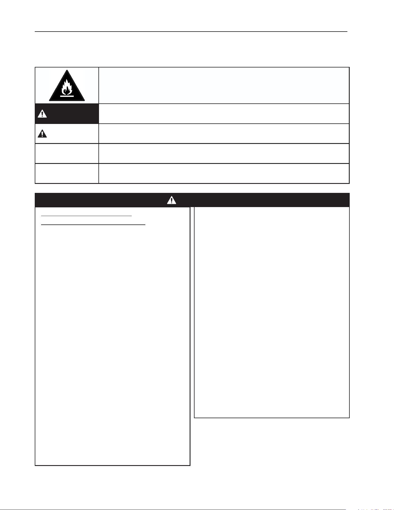
Important Safety Information
Throughout this manual, notices appear to bring your attention to situations which could
result in death, serious injury, damage to the appliance, or damage to property.
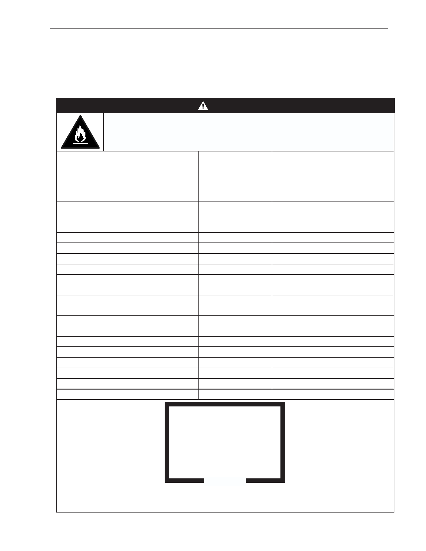
R-290 Class A3 Flammable Refrigerant Used
DANGER
Indicates a hazardous situation that, if not avoided, will result in
death or serious injury.
WARNING
Indicates a hazardous situation that, if not avoided, could result in
death or serious injury.
NOTICE
Indicates a situation that, if not avoided, could result in damage to
the appliance or property.
IMPORTANT
Indicates important information about the use and care of the
appliance.
• Servicing shall be done by trained service
personnel with certied competence
in handling ammable refrigerants to
minimize the risk of possible ignition due
to incorrect parts or improper service.
• Component parts shall be replaced with
like components. so as to minimize the
risk of possible ignition due to incorrect
parts.
• Dispose of properly in accordance with
federal or local regulations.
• Do not pierce or burn.
• Be aware that refrigerants may not contain
an odor.
• Do not damage the refrigeration circuit.
• See nameplate for R-290 refrigerant
charge:
• If greater than 114 g (4 oz.), do not install
in public corridor or lobby.
• If greater than 152 g (5.3 oz.), do not
install within 6 m (20 ft) of open ame.
Risk of Fire or Explosion
Flammable Refrigerant Used
• Only qualied service technicians should
install and service the appliance.
• No installation, operation, or maintenance
should be undertaken until the technician
has thoroughly read this Instruction
Manual. All safety precautions must be
followed.
• No service should be undertaken until
the technician has thoroughly read
the Service Manual available at www.
hoshizakiamerica.com. All safety
precautions must be followed.
• This appliance to be installed in
accordance with the Safety Standard for
Refrigeration Systems ANSI/ASHRAE 15.
• Follow handling instructions carefully in
compliance with national regulations.
• Do not use mechanical devices or other
means to accelerate the defrosting
process or to clean, other than those
recommended by the manufacturer.
• Do not puncture refrigerant tubing. Risk
of re or explosion due to puncture
of refrigerant tubing; follow handling
instructions carefully.
DANGER

5
• The appliance shall be stored in a room
without continuously operating ignition
sources (for example: open ames, an
operating gas appliance, or an operating
electric heater).
• Do not place any potential ignition sources
in or near the appliance.
• Keep clear of obstruction all ventilation
openings in the appliance enclosure or in
the structure for building-in.
• No potential sources of ignition are to be
used in the searching for or detection of
refrigerant leaks.
• Do not use electrical appliances inside
the appliance unless they are of the type
recommended by the manufacturer.
• Do not store explosive substances such as
aerosol cans with a ammable propellant
in this appliance.
• Check that cabling will not be subject
to wear, corrosion, excessive pressure,
vibration, sharp edges, or any other
adverse environmental effects. The check
shall also take into account the effects of
aging or continual vibration from sources
such as compressors or fans.
• Ensure that the area is in the open or that
it is adequately ventilated before breaking
into the system or conducting any hot
work. A degree of ventilation shall continue
during the period that the work is carried
out. The ventilation should safely disperse
any released refrigerant and preferably
expel it externally into the atmosphere.
DANGER continued
Risque D'Incendie ou D'Explosion
Fluide Frigorigène Inammable Utilisé
• Seuls des techniciens de service qualiés
doivent installer et entretenir l'appareil.
• Aucune installation, opération ou
maintenance ne doit être entreprise avant
que le technicien n'ait lu attentivement
ce manuel d'instructions. Toutes les
précautions de sécurité doivent être
suivies.
• Aucune opération d'entretien ne doit
être entreprise avant que le technicien
n'ait lu attentivement le manuel
d'entretien disponible sur le site www.
hoshizakiamerica.com. Toutes les
précautions de sécurité doivent être
suivies.
• Cet appareil doit être installé
conformément à la norme de sécurité
pour les systèmes de réfrigération ANSI/
ASHRAE 15.
• Suivez attentivement les instructions
de manutention conformément aux
réglements nationaux.
• Ne pas utiliser de dispositifs mécaniques
ou d'autres moyens pour accélérer le
processus de dégivrage ou pour nettoyer,
autres que ceux recommandés par le
fabricant.
• Ne pas perforer la conduite de uide
frigorigène. Risque d'incendie ou
d'explosion en cas de perforation d'une
canalisation de uide frigorigène;
suivez attentivement les instructions de
manutention.
• L’entretien doit être effectué par du
personnel formé et certié pour la
manipulation de réfrigérants inammables
an de réduire au minimum le risque
d'inammation dû à des pièces
incorrectes ou à un entretien inadéquat.

6
DANGER continued
• Les pièces doivent être remplacées
par des pièces similaires, de manière
à réduire au minimum le risque
d'inammation dû à des pièces
incorrectes.
• Mettre au rebut conformément aux
réglements fédéraux ou locaux.
• Ne pas percer ou brûler.
• Attention, les uides frigorigénes peuvent
ne pas dégager d'odeur.
• Ne pas endommager les composants du
circuit de réfrigération.
• Voir plaque signalétique pour la charge de
réfrigérant R-290:
• Si elle est supérieure à 114 g (4 oz.), ne
pas l'installer dans un couloir public ou
un hall d'entrée.
• Si elle est supérieure à 152 g (5,3 oz.),
ne pas l'installer à moins de 6 m (20 pi)
d'une amme nue.
• L'appareil doit être entreposé dans
un local ne contenant pas de sources
d'inammation permanentes (ammes
nues, appareil à gaz ou dispositif de
chauffage électrique en fonctionnement,
par exemple).
• Ne placer aucune source d'inammation
potentielle à l'intérieur ou à proximité de
l'appareil.
• Ne pas obstruer les ouvertures de
ventilation dans l'enceinte de l'appareil ou
dans la structure d'encastrement.
• Aucune source potentielle d'inammation
ne doit être utilisée pour rechercher ou
détecter des fuites de réfrigérant.
• Ne pas utiliser d'appareils électriques à
l'intérieur de l'appareil, sauf s'ils sont du
type recommandé par le fabricant.
• Ne pas entreposer dans cet appareil
des substances explosives telles que
des bombes aérosols contenant un gaz
propulseur inammable.
• Vérier que le câblage ne sera pas soumis
à l'usure, à la corrosion, à une pression
excessive, à des vibrations, à des arêtes
vives ou à tout autre effet environnemental
négatif. Le contrôle doit également prendre
en compte les effets du vieillissement ou
des vibrations continues provenant de
sources telles que les compresseurs ou
les ventilateurs.
• S'assurer que la zone est à l'air libre ou
qu'elle est correctement ventilée avant de
pénétrer dans le système ou d'effectuer un
travail à chaud. Une certaine ventilation
doit être maintenue pendant la durée des
travaux. La ventilation doit permettre de
disperser en toute sécurité tout réfrigérant
libéré et, de préférence, de l'expulser dans
l'atmosphère.
7
WARNING
• The appliance should be destined only to
the use for which it has been expressly
conceived. Any other use should be
considered improper and therefore
dangerous. The manufacturer cannot be
held responsible for injury or damage
resulting from improper, incorrect, and
unreasonable use. Failure to install,
operate, and maintain the appliance in
accordance with this manual will adversely
affect safety, performance, component life,
and warranty coverage and may result in
costly water damage.
To reduce the risk of death, electric
shock, serious injury, or re, follow
basic precautions including the
following:
• This appliance is not intended for use
above 2,000 m (6,561 ft).
Installation above 2,000 m (6,561 ft) may
adversely affect safety, performance, and
component life.
• Wear appropriate personal protective
equipment (PPE) when servicing the
appliance.
• The appliance must be installed in
accordance with applicable national, state,
and local codes and regulations.
• The appliance requires an independent
power supply of proper capacity. See the
nameplate for electrical specications.
Failure to use an independent power
supply of proper capacity can result in a
tripped breaker, blown fuse, damage to
existing wiring, or component failure.
This could lead to heat generation or re.
• THE APPLIANCE MUST BE
GROUNDED. The appliance is equipped
with a NEMA5-15 three-prong grounding
plug to reduce the risk of potential
shock hazards. It must be plugged into a
properly grounded, independent 3-prong
wall outlet. If the outlet is a 2-prong outlet,
it is your personal responsibility to have
a qualied electrician replace it with a
properly grounded, independent 3-prong
wall outlet. Do not remove the ground
prong from the power cord and do not use
an adapter plug. Failure to follow these
instructions may result in death, electric
shock, or re.
• To reduce the risk of electric shock, do
not touch the control module or plug with
damp hands.
• To reduce the risk of electric shock,
make sure the appliance is "OFF" before
plugging in or unplugging the appliance.
• Unplug the appliance before servicing.
• Do not use an appliance with a damaged
power cord. The power cord should not be
altered, jerked, bundled, weighed down,
pinched, or tangled. Such actions could
result in electric shock or re. To unplug
the appliance, be sure to pull the plug, not
the cord, and do not jerk the cord.
• Do not use an extension cord.
• If the supply cord is damaged, it must
be replaced by the manufacturer, its
service agent, or similarly qualied
persons in order to avoid a hazard. Upon
replacement, the GREEN ground wire in
the power cord must be connected to the
designated grounding screw.
• Do not make any alterations to the
appliance. Alterations could result in
electric shock, injury, re, or damage to
the appliance.
• Appliance is heavy. Use care when lifting
or positioning. Work in pairs when needed
to prevent injury or damage.

8
• The appliance is not intended for use by
persons (including children) with reduced
physical, sensory, or mental capabilities, or
lack of experience and knowledge, unless
they have been given supervision or
instruction concerning use of the appliance
by a person responsible for their safety.
• Do not splash, pour, or spray water
directly onto or into the appliance. This
might cause short circuit, electric shock,
corrosion, or failure.
• Children should be supervised to ensure
that they do not play with the appliance.
• Do not climb, stand, or hang on the
appliance or allow children or animals to
do so. Serious injury could occur or the
appliance could be damaged.
• Be careful not to pinch ngers when
opening and closing the door. Be careful
when opening and closing the door when
children are in the area.
• Open and close the doors with care.
Opening the doors too quickly or forcefully
may cause injury or damage to the
appliance or surrounding equipment.
• Do not use combustible spray or place
volatile or ammable substances in or near
the appliance. They might catch re.
• Do not throw anything onto the shelves or
load any single shelf with more than 120 lb.
(54.5 kg) of product. They might fall off and
cause injury.
• The appliance is designed only for
temporary storage of food. Employ sanitary
methods. Use for any other purposes (for
example, storage of chemicals or medical
supplies such as vaccine and serum)
could cause deterioration of stored items.
• Do not place any product on the oor of
the cabinet. All product must be placed on
properly installed shelves.
• Do not block air inlets or outlets, otherwise
cooling performance may be reduced.
• Do not tightly pack the cabinet. Allow some
space between items to ensure good air
ow. Also allow space between items and
interior surfaces.
• Do not put warm or hot foods in the
cabinet. Let them cool rst, or they will
raise the cabinet temperature and could
deteriorate other foods in the cabinet or
overload the appliance.
• Food storage and handling must comply
with applicable codes and regulations.
• All foods should be wrapped in plastic lm
or stored in sealed containers. Otherwise
foods may dry up, pass their smells onto
other foods, cause frost to develop, result
in poor appliance performance, or increase
the likelihood of cross-contamination.
Certain dressings and food ingredients,
if not stored in sealed containers, may
accelerate corrosion of the evaporator,
resulting in failure.
• Do not store items near air outlets.
Otherwise, items may freeze up and
crack or break causing a risk of injury or
contamination of other food.
• Do not place more than 20 lb. (9 kg) on
the top panel. Items must be stable and
secure to prevent items from falling off of
the appliance.
• Care should be used when placing items
on top of the appliance. Do not store liquid
containers or items that could fall through
the louvers on top of the appliance. This
could cause electric shock or re.
WARNING continued

9
NOTICE
• Install the appliance in a location that stays
above freezing. Normal operating ambient
temperature must be within 45°F to 100°F
(7°C to 38°C).
• Do not leave the appliance on during
extended periods of non-use, extended
absences, or in sub-freezing temperatures.
To properly prepare the appliance for
these occasions, follow the instructions in
"V. Preparing the Appliance for Periods of
Non-Use."
• Do not place objects on top of the
appliance.
• Protect the oor when moving the
appliance to prevent damage to the oor.
• Do not allow the appliance to bear any
outside weight.
• Keep ventilation openings, in the appliance
enclosure or in the built-in structure, clear
of obstruction.
• Do not allow the appliance to bear any
outside weight.
• To prevent deformation or cracks, do not
spray insecticide onto the plastic parts or
let them come into contact with oil.
• To avoid damage to the gasket, use
only the door handle when opening and
closing.
10
I. Specications
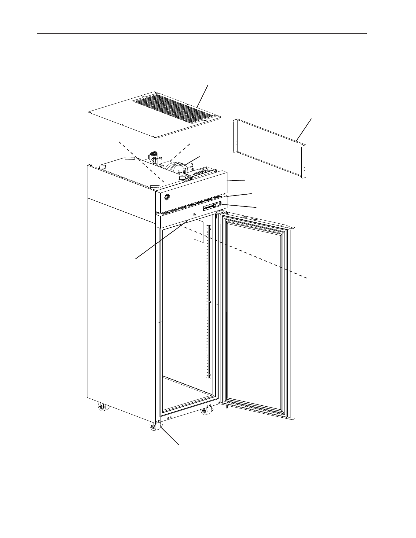
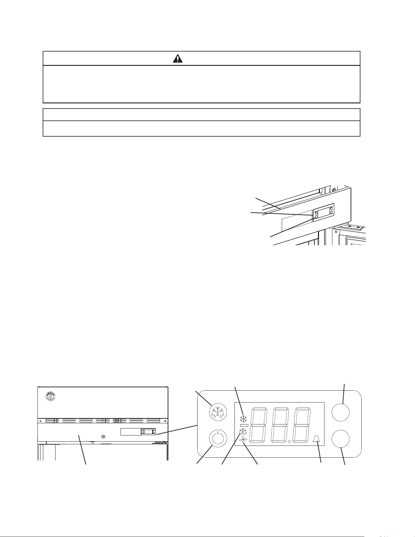
A. Construction
Control Module
Front Panel
Casters
Top Panel
Power Cord
Side Panel
Control Panel
Model Shown: F1A-FS
Defrost Thermistor
Cabinet Thermistor
Compressor
Door Switch

11
B. Electrical and Refrigerant Data
The nameplate provides electrical and refrigerant data and Year of Manufacture (YOM).
The nameplate is located on the rear panel. For certication marks, see the nameplate.
We reserve the right to make changes in specications and design without prior notice.
Model Number R1A-FS(-FSL)(-FSJ)(-FSLJ)
(-FSCL)(-FSCR)(-HS)(-HSL)
R2A-FS(-FSN)(-FSC)(-HS)
AC SUPPLY VOLTAGE ~115/60/1 ~115/60/1
AMPERES 5 8
DESIGN PRESSURE kPa (PSI) HI-2482 (360) LO-1310 (190) HI-2482 (360) LO-1310 (190)
REFRIGERANT g (oz.) R-290 130 (4.6) R-290 140 (4.9)
CLIMATIC CLASS 5 5
INSULATION BLOWING GAS HFO 1233zd(E) HFO 1233zd(E)
MINIMUM ROOM FLOOR AREA m² (ft² ) 6.2 (67) 6.7 (72.1)
Model Number R3A-FS(-FSCL)(-FSCR)(-HS)
AC SUPPLY VOLTAGE ~115/60/1
AMPERES 9.5
DESIGN PRESSURE kPa (PSI) HI-2482 (360) LO-1310 (190)
REFRIGERANT g (oz.) R-290 130 (4.6)
CLIMATIC CLASS 5
INSULATION BLOWING GAS HFO 1233zd(E)
MINIMUM ROOM FLOOR AREA m² (ft² ) 6.2 (67)
Model Number PT1A-FS-FS(-HS-HS)
(-FG-FG)(-FGE-FGE)
PT2A-FS-FS(-HS-HS)(-FG-FG)
AC SUPPLY VOLTAGE ~115/60/1 ~115/60/1
AMPERES 5 8
DESIGN PRESSURE kPa (PSI) HI-2482 (360) LO-1310 (190) HI-2482 (360) LO-1310 (190)
REFRIGERANT g (oz.) R-290 130 (4.6) R-290 150 (5.3)
CLIMATIC CLASS 5 5
INSULATION BLOWING GAS HFO 1233zd(E) HFO 1233zd(E)
MINIMUM ROOM FLOOR AREA m² (ft² ) 6.2 (67) 7.2 (77.3)
Model Number RN1A-FS
RT1A-FS-FS
RN2A-FS
RT2A-FS-FS
AC SUPPLY VOLTAGE ~115/60/1 ~115/60/1
AMPERES 6.4 8.2
DESIGN PRESSURE kPa (PSI) HI-2482 (360) LO-1310 (190) HI-2482 (360) LO-1310 (190)
REFRIGERANT g (oz.) R-290 130 (4.6) R-290 145 (5.1)
CLIMATIC CLASS 5 5
INSULATION BLOWING GAS HFO 1233zd(E) HFO 1233zd(E)
MINIMUM ROOM FLOOR AREA m² (ft² ) 6.2 (67) 6.9 (74.4)
Model Number F1A-FS(-FSL)(-HS)(-HSL)
PTF1A-HS-HS(-HGE-HGE)
F2A-FS(-FSN)(-HS)
AC SUPPLY VOLTAGE ~115/60/1 ~115/60/1
AMPERES 9 9.5
DESIGN PRESSURE kPa (PSI) HI-2482 (360) LO-1310 (190) HI-2482 (360) LO-1310 (190)
REFRIGERANT g (oz.) R-290 115 (4.1) R-290 120 (4.2)
CLIMATIC CLASS 5 5
INSULATION BLOWING GAS HFO 1233zd(E) HFO 1233zd(E)
MINIMUM ROOM FLOOR AREA m² (ft² ) 5.5 (59.2) 5.7 (61.8)

12
Model Number F3A-FS(-HS)
AC SUPPLY VOLTAGE ~115/60/1
AMPERES 11
DESIGN PRESSURE kPa (PSI) HI-2482 (360) LO-1310 (190)
REFRIGERANT g (oz.) R-290 115 (4.1)
CLIMATIC CLASS 5
INSULATION BLOWING GAS HFO 1233zd(E)
MINIMUM ROOM FLOOR AREA m² (ft² ) 5.5 (59.2)
Model Number DT1A-HS
Refrigerator Freezer
AC SUPPLY VOLTAGE ~115/60/1 ~115/60/1
AMPERES 5.5 5.5
DESIGN PRESSURE kPa (PSI) HI-2482 (360) LO-1310 (190) HI-2482 (360) LO-1310 (190)
REFRIGERANT g (oz.) R-290 60 (2.1) R-290 70 (2.5)
CLIMATIC CLASS 5 5
INSULATION BLOWING GAS HFO 1233zd(E) HFO 1233zd(E)
MINIMUM ROOM FLOOR AREA m² (ft² ) 3.3 (36.1) 3.3 (36.1)
Model Number DT2A-FS/HS
Refrigerator Freezer
AC SUPPLY VOLTAGE ~115/60/1 ~115/60/1
AMPERES 14 14
DESIGN PRESSURE kPa (PSI) HI-2482 (360) LO-1310 (190) HI-2482 (360) LO-1310 (190)
REFRIGERANT g (oz.) R-290 130 (4.6) R-290 115 (4.1)
CLIMATIC CLASS 5 5
INSULATION BLOWING GAS HFO 1233zd(E) HFO 1233zd(E)
MINIMUM ROOM FLOOR AREA m² (ft² ) 6.2 (67) 6.2 (67)
Note: Climatic Class 5: This appliance electrical safety tested for operation in maximum
ambient temperature of 104°F (40°C) with 40% relative humidity. However,
normal operating ambient temperature for refrigerator and solid door freezers
must be within 45°F to 100°F (7°C to 38°C) and for glass door freezers 45°F to
80°F (7°C to 27°C). Operation of the appliance, for extended periods, outside of
these normal temperature ranges may affect appliance performance.
13
II. Installation Instructions
A. Location
This appliance is approved for indoor use.
This appliance uses an A3 ammable refrigerant. For refrigerant charge and minimum
room oor area, see the table below.
DANGER
R-290 Class A3 Flammable Refrigerant Used
Model
R-290 Refrigerant
Charge g (oz.)
Minimum Room Floor Area
(operating or storage)
Supercie Minimale du Local
(service ou stockage)
m² (ft²); m² (pi²)
R1A-FG(-FGCL)(-FGCR)(-HG)
R1A-FS(-FSJ)(-FSL)(-FSLJ)(-FSCL)
(-FDCR)(-HS)(-HSL)
130 (4.6) 6.2 (67)
R2A-FG(-HG)(-FS)(-HS)(-FSN)(-FSC) 140 (4.9) 6.7 (72.1)
R3A-FS(-FSCL)(-FSCR)(-HS) 130 (4.6) 6.2 (67)
PT1A-FS-FS(-HS-HS)(-FG-FG) 130 (4.6) 6.2 (67)
PT2A-FS-FS(-HS-HS)(-FG-FG) 150 (5.3) 7.2 (77.3)
RN1A-FS
RT1A-FS-FS
130 (4.6) 6.2 (67)
RN2A-FS
RT2A-FS-FS
145 (5.1) 6.9 (74.7)
F1A-FG(-FS)(-FSL)(-HG)(-HS)(-HSL)
PTF1A-FS-FS(-HS-HS)(-FG-FG)
115 (4.1) 59.2 (5.5)
F2A-FG(-HG)(-FS)(-HS) 120 (4.2) 5.7 (61.8)
F3A-FS(-HS) 115 (4.6) 5.5 (59.2)
DT1A-HS - Refrigerator
60 (2.1) 3.3 (36.1)
DT1A-HS - Freezer 70 (2.5) 3.3 (36.1)
DT2A-FS(-HS) - Refrigerator 130 (4.6) 6.2 (67)
DT2A-FS(-HS) - Freezer 115 (4.1) 6.2 (67)
≥ Area m
2
(ft
2
) (see "Minimum Room Floor Area" above)
≥ Supercie m
2
(pi
2
) (voir « Supercie Minimale du Local » ci-dessus)
14
DANGER continued
R-290 Refrigerant Charge:
• If greater than 114 g (4 oz.), do not install in public corridor or lobby.
• If greater than 152 g (5.3 oz.), do not install within 6 m (20 ft) of open ame.
Charge de réfrigérant R-290:
• Si elle est supérieure à 114 g (4 oz.), ne pas l'installer dans un couloir public ou un hall
d'entrée.
• Si elle est supérieure à 152 g (5,3 oz.), ne pas l'installer à moins de 6 m (20 pi) d'une
amme nue.
This appliance is not intended for use above 2,000 m (6,561 ft). Installation above 2,000
m (6,561 ft) may adversely affect safety, performance, and component life.
WARNING
• The appliance must be installed in accordance with applicable national, state, and
local regulations.
• Appliance is heavy. Use care when lifting or positioning. Work in pairs when needed to
prevent injury or damage. Do not lift using the top section or the drawers.
• Do not tilt the appliance more than 45°.
• The appliance is not intended for outdoor use.
• This appliance to be installed in accordance with the Safety Standard for Refrigeration
Systems ANSI/ASHRAE 15
• Normal operating ambient temperature for refrigerator and solid door freezers must
be within 45°F to 100°F (7°C to 38°C) and for glass door freezers 45°F to 80°F (7°C
to 27°C). Operation of the appliance, for extended periods, outside of this normal
temperature range may affect appliance performance.
• The appliance must not be located next to ovens, grills, or other high heat producing
equipment.
• The location must provide a rm and level foundation for the appliance.
• The appliance must not be located in a corrosive environment.
• Minimum Clearance
Models Side Top Rear
Reach-In Refrigerators and Freezers
(Except Roll-In's, Roll-Thru's, Pass-Thru's, and 2-Section Freezers)
0" (0 cm) 0" (0 cm) 3" (8 cm)
Reach-In Refrigerators Roll-In's 0" (0 cm) 10" (25 cm) 0" (0 cm)
Reach-In Refrigerators Roll-Thru's and Pass-Thru's 0" (0 cm) 0" (0 cm) N/A
2-Section Freezers 0" (0 cm) 10" (25 cm) 3" (8 cm)
15
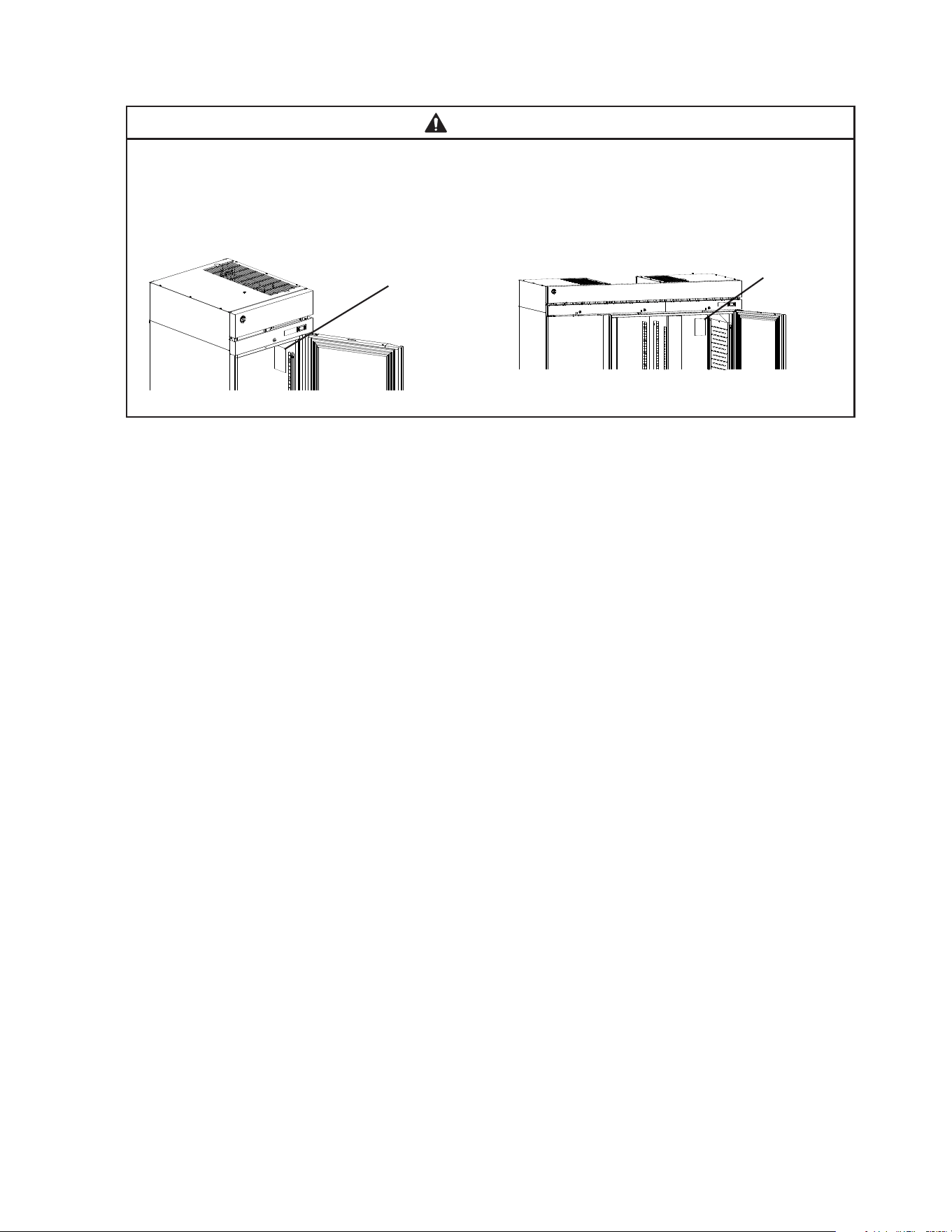
B. Checks Before Installation
WARNING
Refer to the nameplate for electrical specications. The nameplate is located on the
right side wall of the 1 and 2 section cabinet interior and the rear wall of the
3 section cabinet interior. For more electrical connection details, see "I.G. Electrical
Connection." We reserve the right to make specication and design changes
without prior notice.
• Visually inspect the exterior of the shipping package and immediately report any damage
to the carrier. Upon opening the package, any concealed damage should also be
immediately reported to the carrier.
• Remove the shipping carton, tape, and packing material. Remove the protective plastic
lm from the exterior panels on all models and from the interior door panels on solid
door models. If the appliance is exposed to the sun or to heat, remove the lm after the
appliance cools.
• Remove all accessory containers before discarding the packing materials. Dispose of all
packing materials in a proper and environmentally responsible manner.
• Check for missing or damaged accessories.
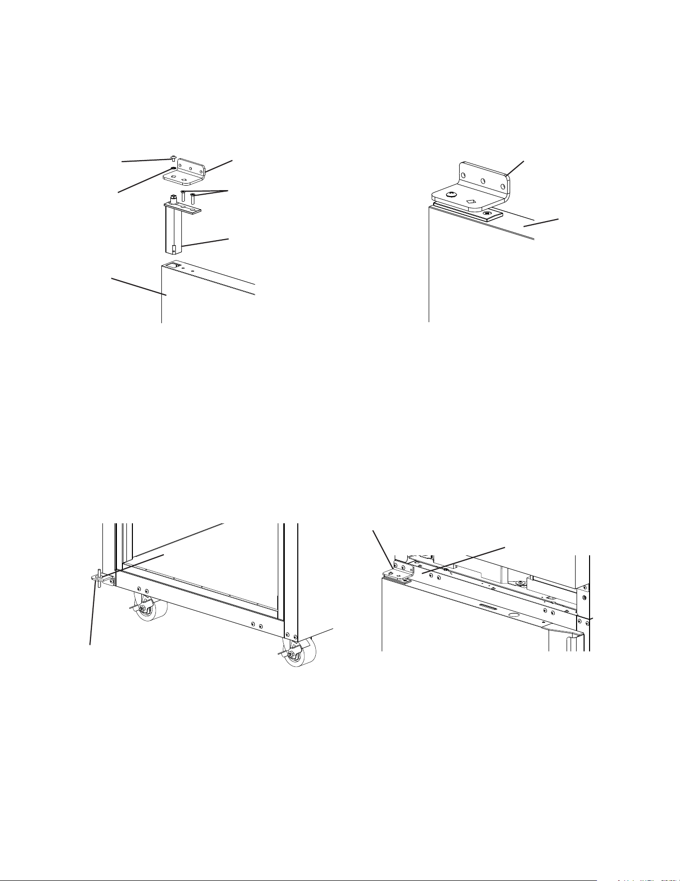
Nameplate
Fig. 1
Nameplate
Model Shown: R1A-FS
Model Shown: R3A-FS
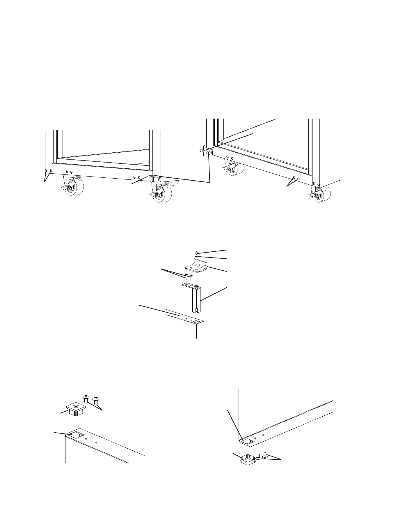
16
C. Setup
1. Caster or Optional 6 in. Leg Installation and Leveling the Appliance
a) Caster or Optional 6 in. Leg Installation
1) Move as close to the nal location as possible.
2) Remove the 2 bolts securing the appliance to the pallet, then remove the appliance
from the pallet. Block the appliance securely at a height of 8" (20cm) off the oor.
Do not lay the appliance down. NOTICE! Do not allow the door(s) to bear the weight
of the appliance.
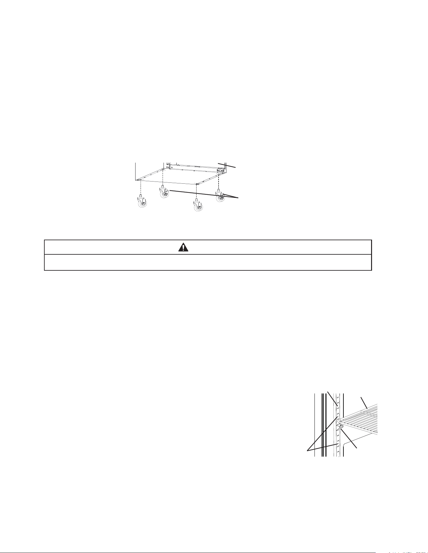
a) Casters: Attach and tighten the casters to the bottom of the appliance. Locking casters
should be attached to the front of the appliance for standard models and on the
service (control module) side on pass-thru models. See Fig. 2.
NOTICE! Ensure casters are completely threaded into appliance and tight.
b) Legs: Optional 6 in. legs available. Attach and tighten the optional adjustable 6 in. legs
to the bottom of the appliance.
WARNING
When using legs, avoid sliding the appliance across the oor after legs are installed.
b) Leveling the Appliance
After installing the casters or optional 6 in. legs, lower the appliance to the oor and
check the level of the appliance.
a) Casters: If the appliance is out of level, follow the instructions and steps found in
HS-3590 provided in the accessories bag. Otherwise, continue to the next section.
NOTICE! Make sure the casters are tight and no slack is left between the
casters, shim plates, and appliance.
b) Legs: If the appliance is out of level , turn the bottom portion of the leg for height
adjustment. Otherwise, continue to the next section. NOTICE! Make sure the legs
are tight and no slack is left between the leg and appliance.
2. Install the Shelves
Shelf support clips are provided in the accessory pack.
1) Place the shelf support clips into the pilasters (4 shelf
support clips per shelf). Indexing holes are provided on the
pilasters in evenly spaced intervals to assist in positioning
the support clips at the same height. See Fig. 3.
2) Place the shelves in position on the shelf support clips.
3. Check the Refrigeration Circuit
1) Visually check that the refrigerant lines do not rub or touch other lines or surfaces and
that the condenser fan blade turns freely.
2) Check that the compressor is snug on all mounting pads.
Front of Appliance (standard models)
or Service (control module) Side
(pass-thru models)
Locking Casters
Fig. 2
Shelf
Support
Clip
Indexing
Holes
Pilaster
Shelf
Fig. 3
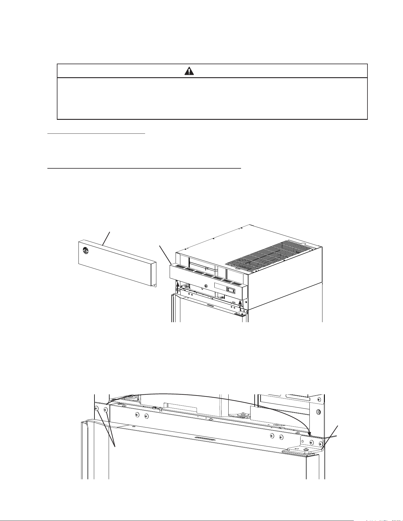
17
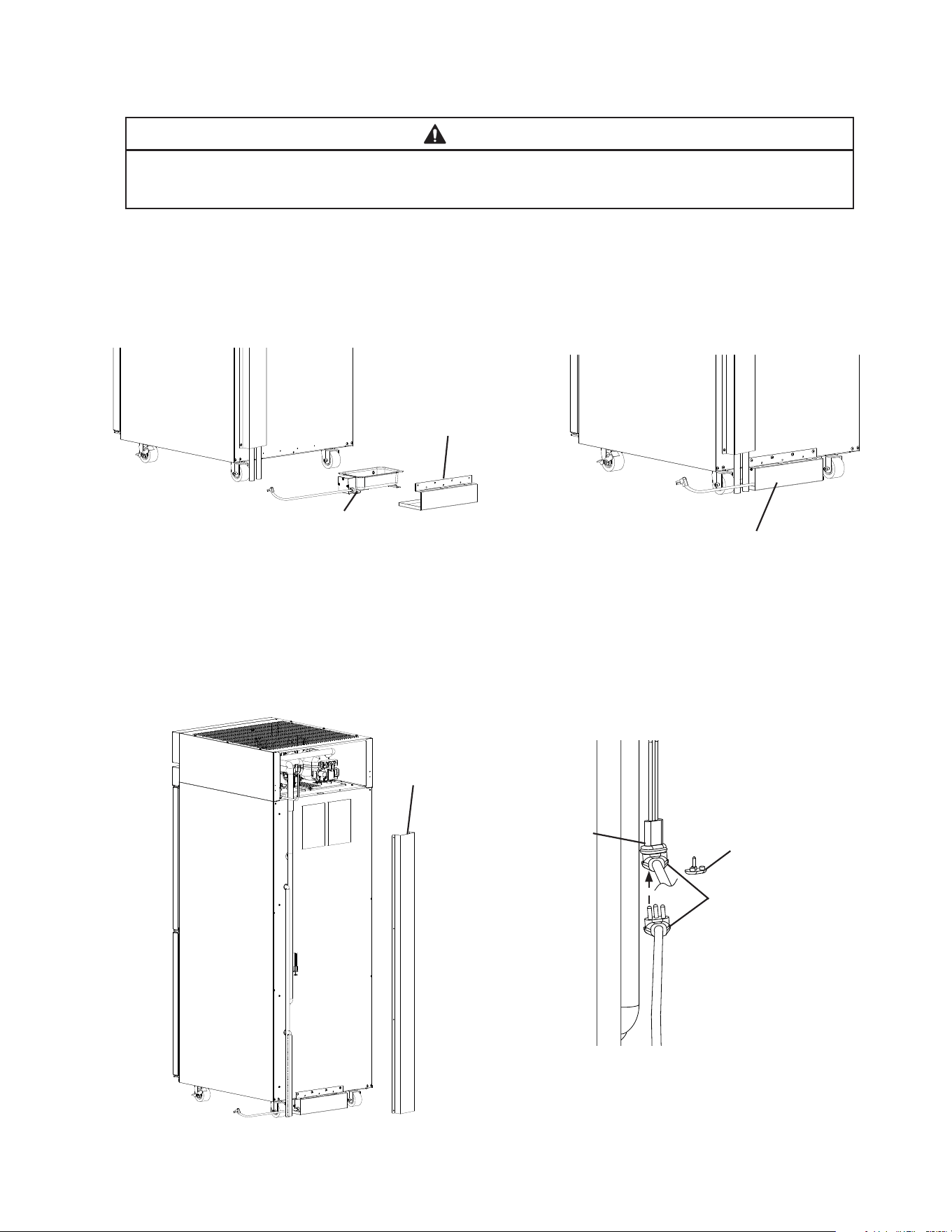
D. DT1A-HS Heated Condensate Pan Installation
WARNING
Failure to install the heated condensate pan in accordance with this manual could
adversely affect safety and result in costly water damage.
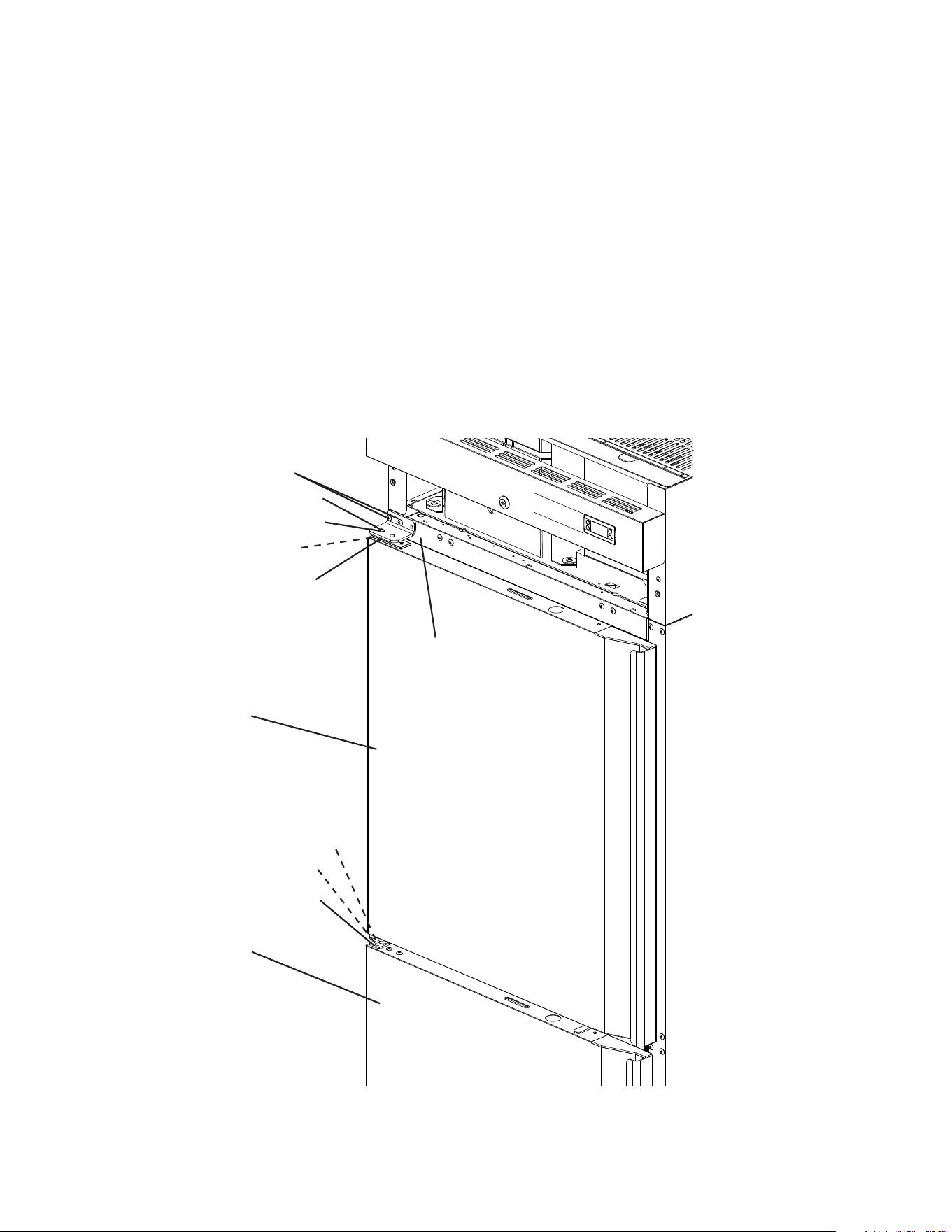
1) Remove the heated condensate pan and heated condensate pan bracket from the
accessory bag.
2) Place the heated condensate pan in the heated condensate pan bracket, then using the
4 screws provided in the accessory bag, secure the heated condensate pan bracket to
the rear of the appliance. See Fig. 4.
3) Remove the channel cover from the back of the appliance. See Fig. 5.
4) Remove the heated condensate pan receptacle cover from the heated condensate pan
receptacle. Next, plug the heated condensate pan plug into the heated condensate pan
receptacle. See Fig. 6.
Fig. 4
Heated
Condensate
Pan
Heated
Condensate
Pan Bracket
Heated
Condensate
Pan Assembly
Heated
Condensate
Pan Plug
Heated
Condensate
Pan Receptacle
Cover
Heated
Condensate Pan
Receptacle
Fig. 5
Fig. 6
Channel Cover
18
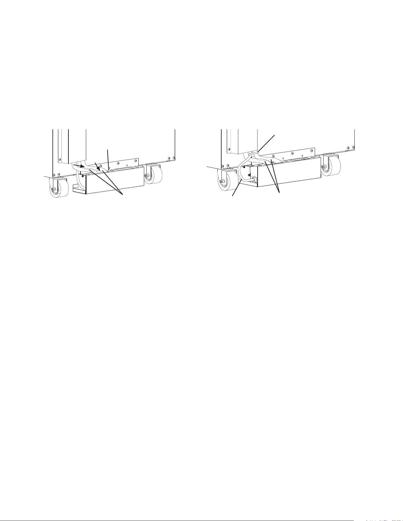
5) Replace the channel cover in its correct position.
6) Route the drain hoses into the heated condensate pan assembly. See Fig. 7.
Warning! Conrm that the drain hoses does not contact the heater. Adjust as
necessary.
7) Using a nylon tie from the accessory bag, secure the heated condensate pan power
supply cord to one of the drain hoses. See Fig. 8.
8) Place the appliance in its nal location.
Fig. 7
Fig. 8
Nylon Tie
Heated
Condensate
Pan Power
Supply Cord
Drain Hoses
Drain Hoses
Heated
Condensate
Pan Assembly
19
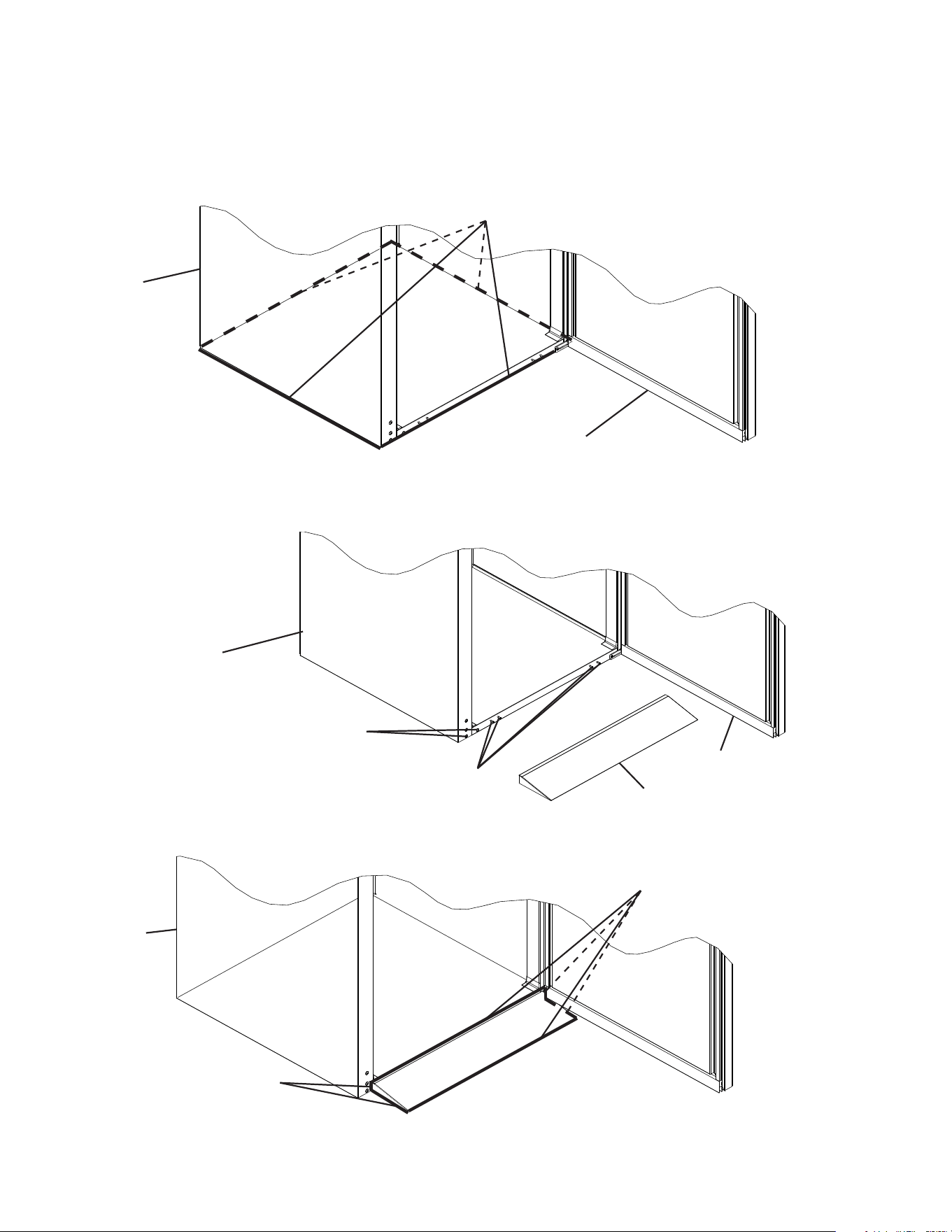
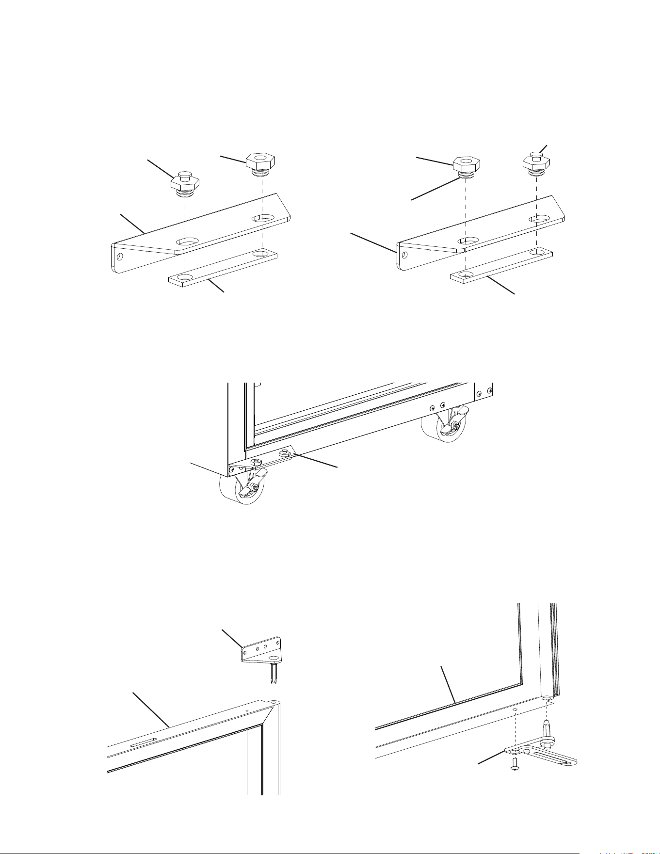
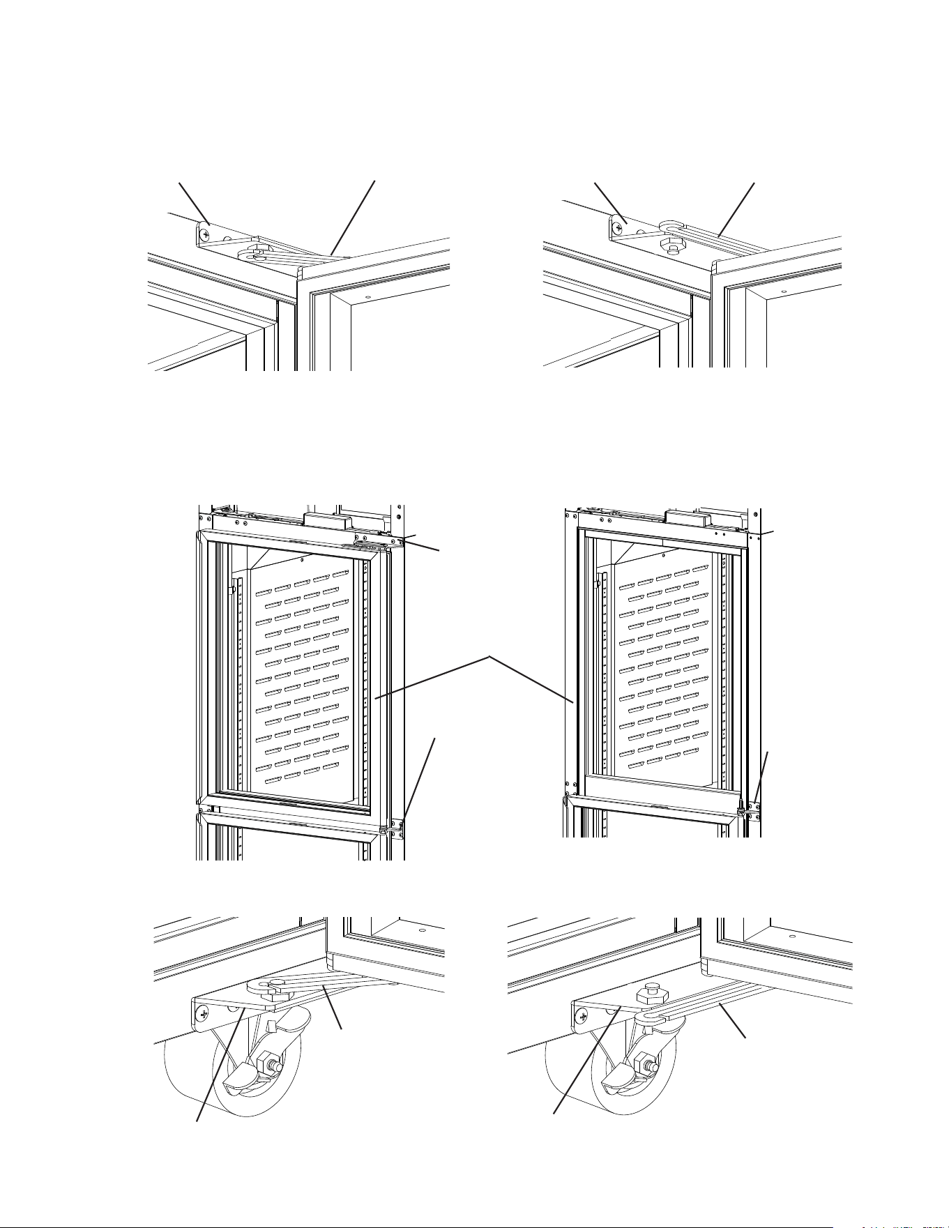
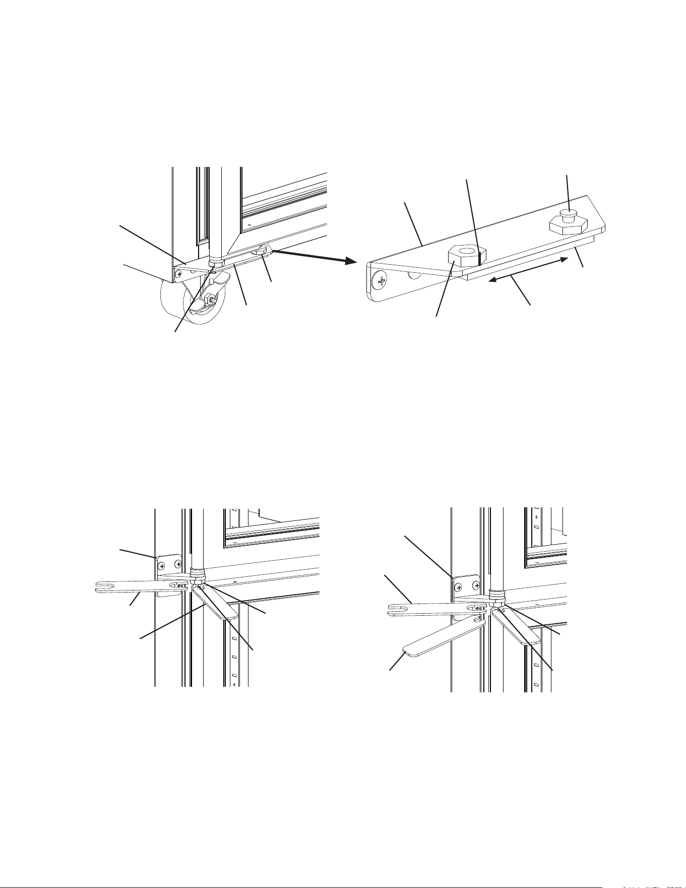
E. Food Cart Ramp (Roll-In/Roll-Thru Appliances)
Conrm the area where the appliance is to be installed is at and level.
1) Place the appliance in position, then seal the perimeter where the appliance contacts
the oor with approved caulk compound in a smooth and easily cleanable manner.
See Fig. 9.
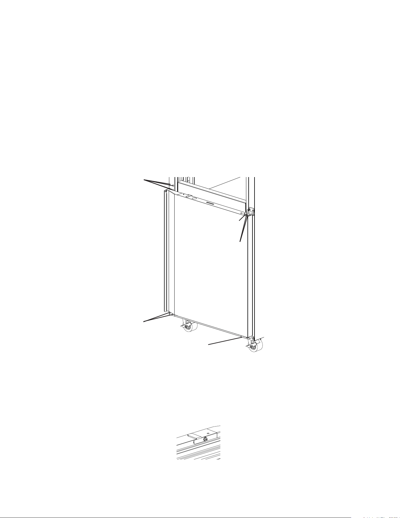
2) Remove the 2 ller screws from the bottom of the appliance. See Fig. 10. Next, loosen
the 4 truss head screws at the bottom of the appliance 3 to 4 mm (1/8"), then lay the
ramp onto the loosened truss head screws. See Fig. 10.
Caulk Compound
Caulk Compound
Fig. 9
Fig. 11
Body
Caulk Compound
3) Seal around the ramp as shown in Fig. 11 with an approved caulk compound.
Filler Screws
Food Cart Ramp
Fig. 10
Door
Body
Door
Truss Head Screws
Door Hinge
Body
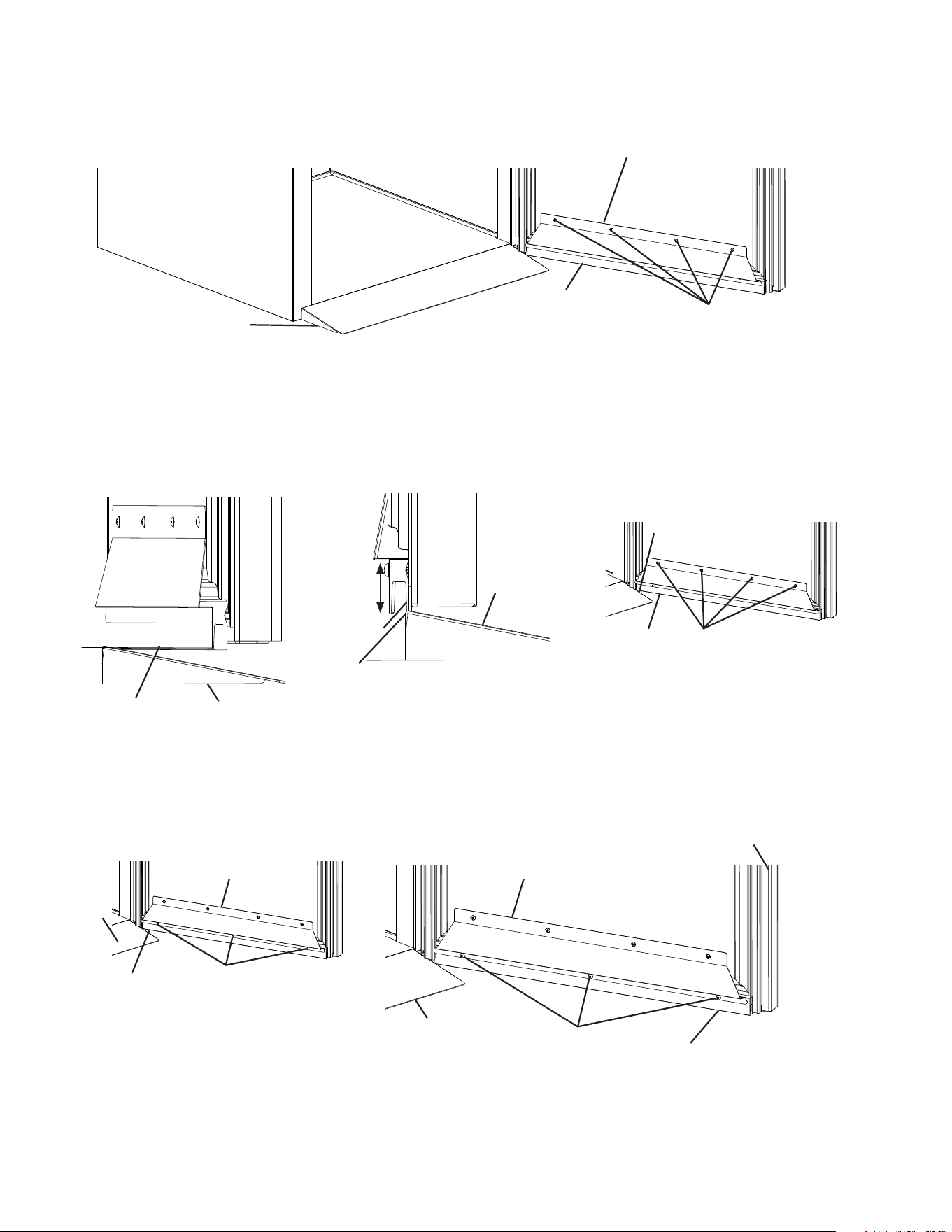
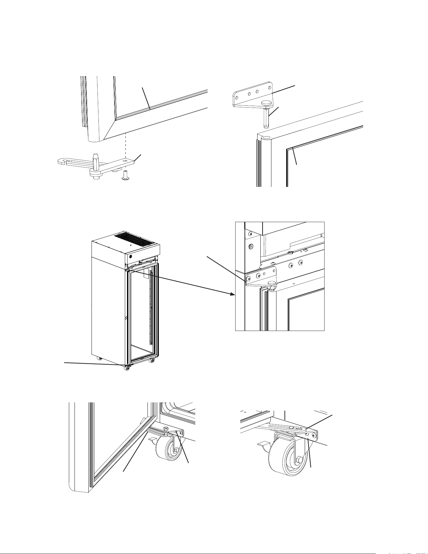
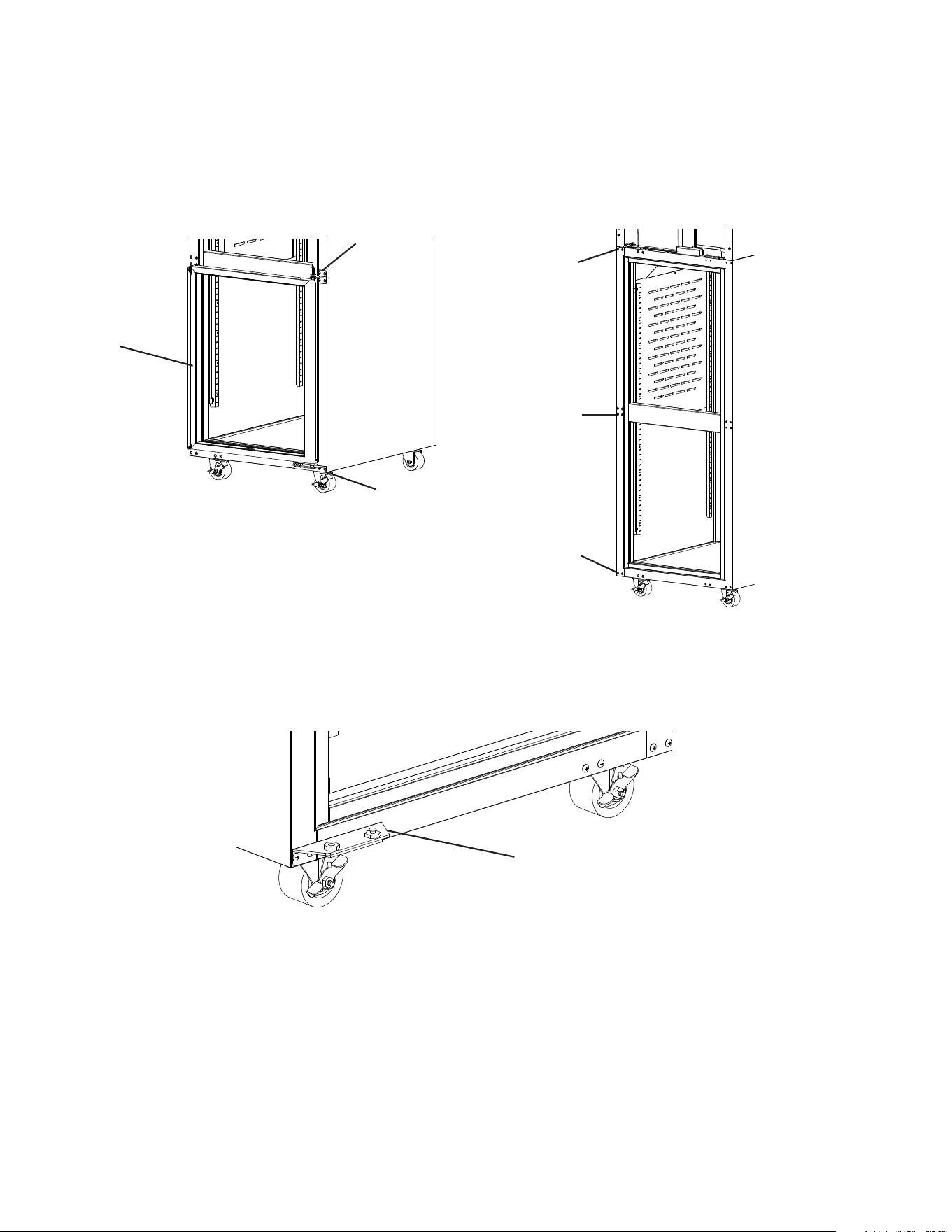
20
4) Loosen the door sweep bracket adjustment screws. See Fig. 12.
Fig. 12
Ramp
Door Sweep Bracket
5) Adjust the door sweep so that the door sweep touches the ramp when the door is
closed. See Fig. 13. Once in its correct position, tighten the door sweep bracket
adjustment screws.
6) Drill three 1/8" pilot holes in the positions shown in Fig. 14. Use the 3 screws provided in
the accessory bag to secure the door sweep to the door sweep bracket and the door.
Door Sweep Bracket
Adjustment Screws
Fig. 13
Door Sweep
Ramp
Door Sweep
Fig. 14
Door Sweep
Door Open Door Closed
Ramp
Ramp
Door Sweep
Adjust so that door sweep touches
ramp with door closed.
Door Sweep Bracket
Adjustment Screws
Door Sweep
Screws 1/8"
pilot holes
Door
Door Sweep
Screws
Door Sweep Bracket Door Sweep Bracket
Ramp
Ramp
Door Sweep
Door Sweep
21
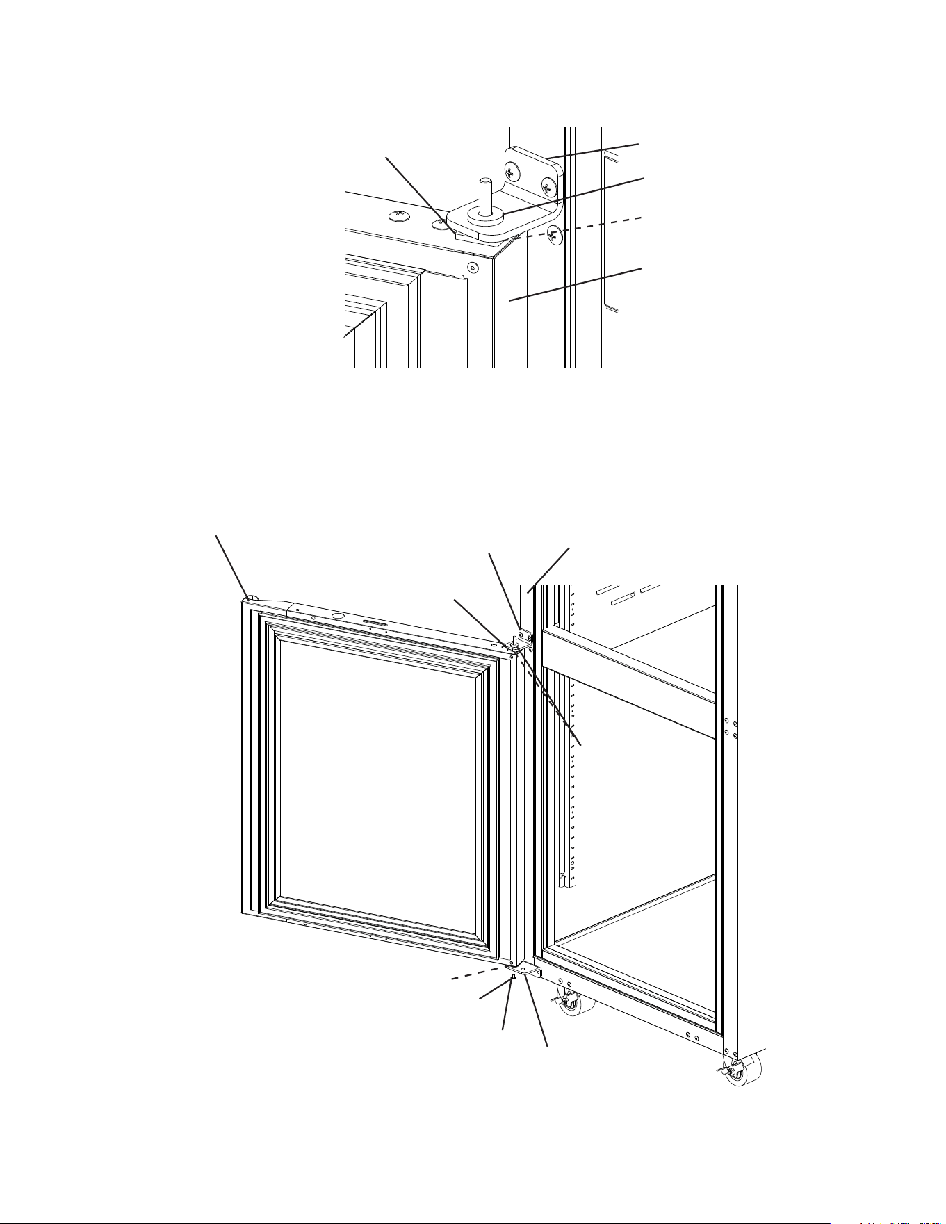
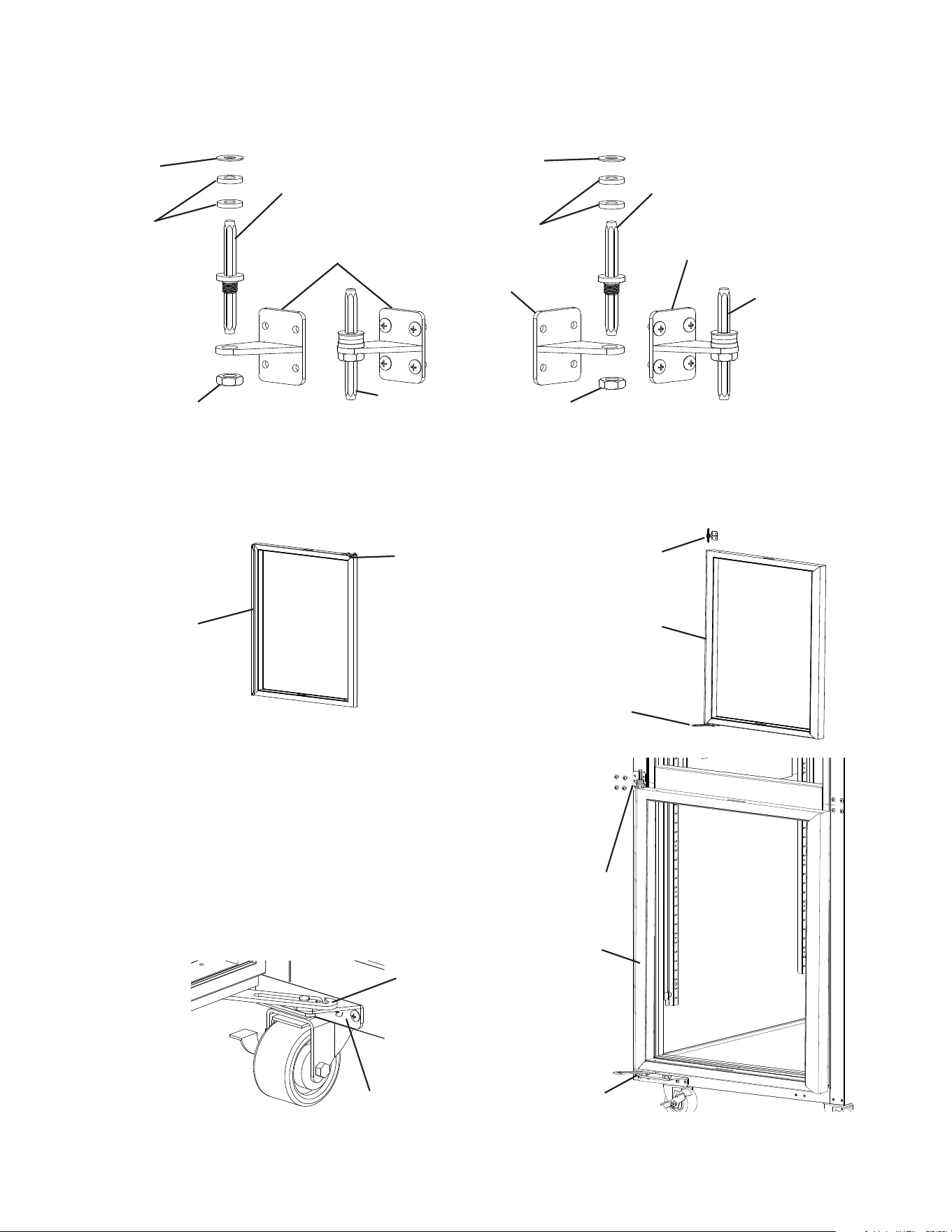
3) While maintaining a hold on the door, remove the upper hinge bracket then lift the door
up off the bottom hinge and set aside. See Fig. 16. Remove the ller screws from the
opposite side upper hinge bracket holes and mount them into the holes of the removed
upper hinge bracket. NOTICE! Be sure to reuse the bracket screws for mounting the
bracket as the bracket screws are 5×12 and ller screws are 5×10.
Fig. 15
F. Door Reversal
This appliance is provided with a cabinet design which, after being delivered to the
installation location, permits changing of the door swing from left to right or right to left.
WARNING
• Wear proper PPE (personal protection equipment) when executing these
procedures (safety glasses and gloves).
• Keep ngers away from edge of upper hinge bracket. Spring cartridge can cause
the upper hinge bracket to move suddenly with extreme force.
1. Full Solid Door Reversal
Note: Hinge brackets, and spring cartridge are universal and can be used in both left and
right-hinged applications.
Example shows change from right hinged to left hinged.
1) Lock the casters.
2) Remove the front panel, then being careful not to pull the wires on the control module
and door switch(es), remove the control panel. Secure the control panel so that it does
not interfere with the hinge bracket and will not fall. See Fig. 15.
Fig. 16
Front Panel
Filler Screws
Upper Hinge
Bracket
Control Panel
22
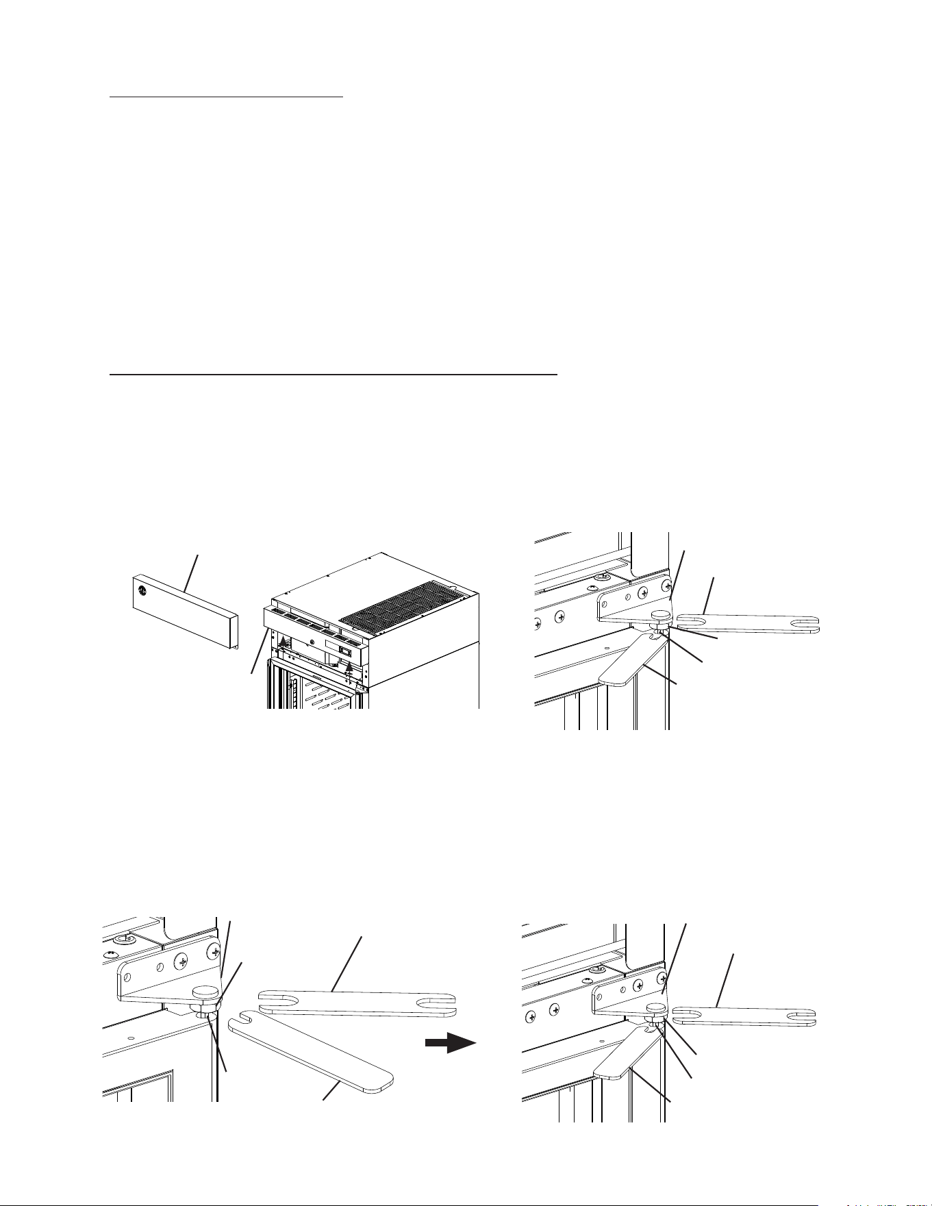
4) Remove the lower hinge bracket and thrust washer. See Fig. 17. Retain thrust washer
for opposite side lower hinge bracket installation. Remove the ller screws from the
opposite side lower hinge bracket holes and mount them into the holes of the removed
lower hinge bracket. NOTICE! Be sure to reuse the bracket screws for mounting the
bracket as the bracket screws are 5×12 and ller screws are 5×10.
5) Secure the lower hinge bracket to the opposite side lower hinge bracket location, then
place the thrust-washer on the lower hinge bracket. See Fig. 18.
6) Remove the screw and washer securing the upper hinge bracket to the spring cartridge.
Remove the 2 screws securing the spring cartridge to the door, then remove the spring
cartridge from the door. See Fig. 19.
Fig. 18
Fig. 19
Filler
Screws
Thrust Washer
Spring Cartridge Screws
Upper Hinge Bracket Screw
Fig. 20
7) Rotate the door 180 degrees, to its new orientation. Remove the nylon bearing and ller
screws. See Fig. 20. NOTICE! Care should be taken not to damage the door. Mount
the nylon bearing and ller screws into the holes left by the spring cartridge in the lower
section of the door. See Fig. 21.
Fig. 17
Fig. 21
Filler
Screws
Thrust Washer
Lower Hinge
Bracket
Upper Hinge Bracket Washer
Upper Hinge Bracket
Spring Cartridge
Door
Filler Screws
Nylon
Bearing
Nylon
Bearing
Hole
Filler Screws
Nylon
Bearing
Formerly Spring
Cartridge Hole
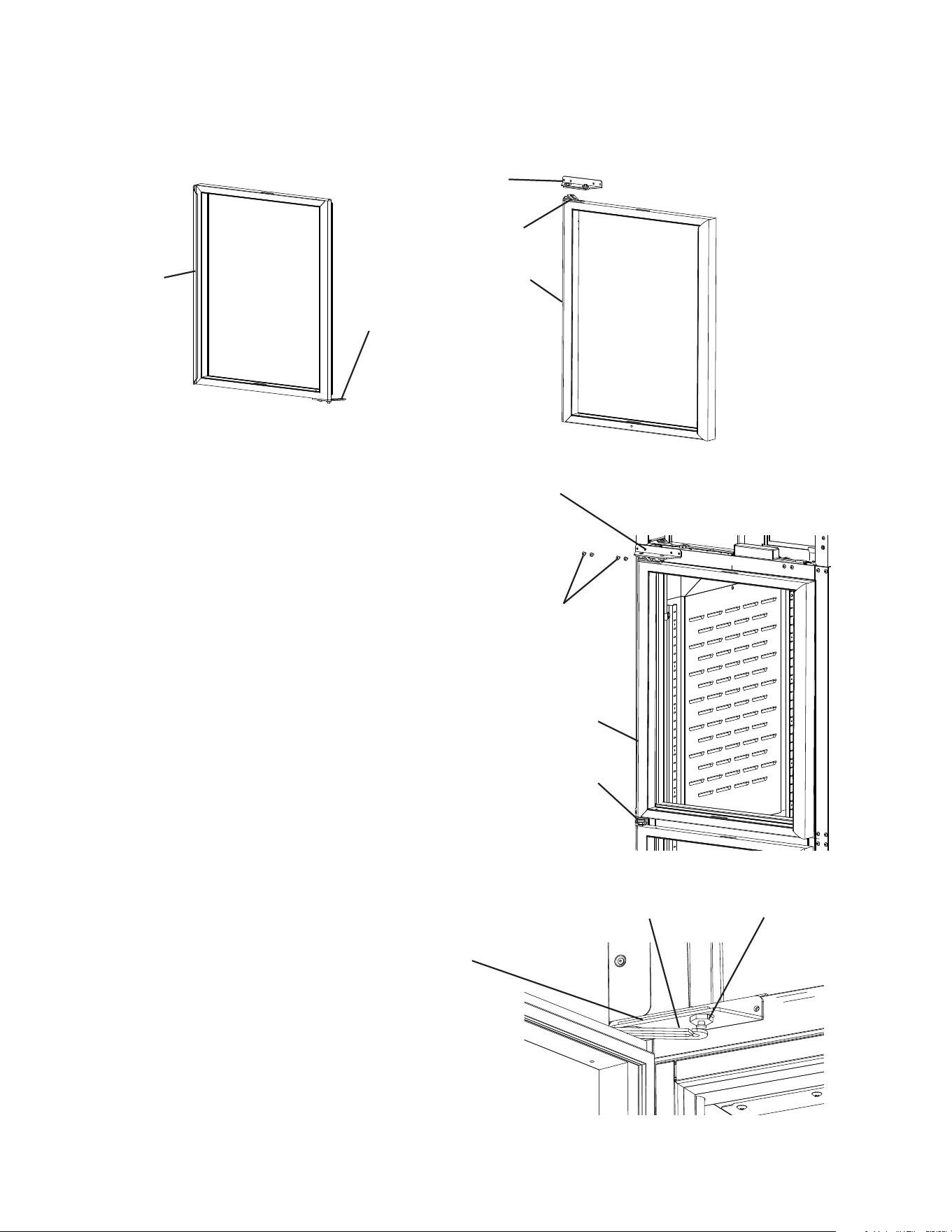
23
8) Clear foam from the spring cartridge hole to allow for spring cartridge installation. Install
the spring cartridge and secure it to the door using the spring cartridge screws removed
in step 6. See Fig. 22. Next, align the upper hinge bracket to the door in the orientation
that allows for closed door installation. See Fig. 23. Secure the upper hinge bracket to
the door using the screw and washer removed in step 6.
Fig. 22
Upper Hinge
Bracket Screw
Upper Hinge
Bracket Washer
Door
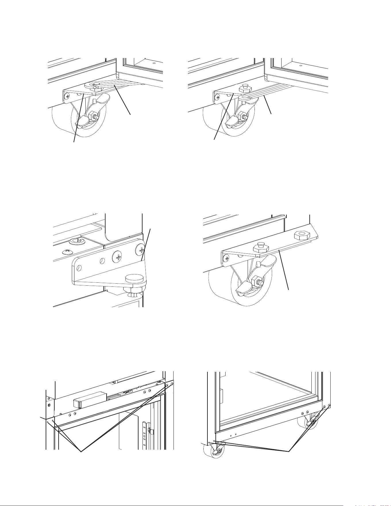
9) Make sure the thrust washer is in place, then mount the door onto the lower hinge
bracket (nylon bearing over lower hinge bracket pin). See Fig. 24.
10) Secure the upper hinge bracket to the appliance. See Fig. 25.
11) Verify swing. Move the control panel hole plugs to the other side, then replace and
secure the control panel and front panel in their correct positions. Verify the door switch
and lock function.
Fig. 24 Fig. 25
Fig. 23
Upper Hinge
Bracket
Spring Cartridge
Screws
Spring Cartridge
Door
Upper Hinge Bracket
Upper Hinge Bracket
Lower Hinge Bracket
Thrust Washer
Cabinet
24
2. Half Solid Door Reversal
Note: Hinge brackets, and spring cartridge are universal and can be used in both left and
right-hinged applications.
Example shows change from right hinged to left hinged.
1) Lock the casters.
2) Remove the front panel, then being careful not to pull the wires on the control module
and door switch(es), remove the control panel. Secure the control panel so that it does
not interfere with the hinge bracket and will not fall. See Fig. 26.
Upper Hinge Bracket
Fig. 28
4) Rotate the upper hinge bracket 180 degrees counter clockwise. See Fig. 28.
Next, remove the spring cartridge screw and washer, then remove the upper hinge
bracket and thrust washers (2). Set the door aside. Retain the upper hinge bracket
thrust washers for opposite side hinge bracket installation.
Fig. 26
Front Panel
Control Panel
Filler Screws Upper Hinge Bracket
3) While maintaining a hold on the upper door, remove the upper hinge bracket then lift
the door off the center hinge bracket. See Fig. 27. Retain the upper center hinge bracket
thrust-washer for opposite side hinge bracket installation.
Center Hinge Bracket
Upper Thrust Washer
Fig. 27
Thrust Washers (2)
Rotate 180 degrees CCW
Spring Cartridge Screw and Washer
25
8) Remove the door latch from the lower door. See Fig. 30.
5) Remove the ller screws from the opposite side upper hinge bracket holes and mount
them into the holes of the removed upper hinge bracket. NOTICE! Be sure to reuse the
hinge bracket screws for mounting the hinge bracket as the hinge bracket screws
are 5×12 and ller screws are 5×10.
6) While maintaining a hold on the lower door, remove the lower hinge bracket from the
cabinet, then lower the door off the center hinge bracket and set aside. See Fig. 29.
Retain the center hinge thrust washers for opposite side installation.
7) Remove the center hinge bracket from the cabinet. Remove the ller screws from the
opposite side lower and center hinge bracket holes and mount them into the holes of
the removed lower and center hinge brackets. NOTICE! Be sure to reuse the hinge
bracket screws for mounting the hinge brackets as the hinge bracket screws are
5×12 and ller screws are 5×10.
Latch
Screw-Bolt with
Threadlocker (5×16, SS)
Fig. 29
Lower Hinge Bracket
Center Hinge Bracket
Filler Screws
Fig. 30
Thrust Washers
Filler Screws
26
9) Remove the lower hinge bracket spring cartridge screw, washer, and thrust washers
from the door. Set the door aside. Next, secure the lower hinge bracket to the opposite
side. Make sure the lower thrust-washers are in place. See Fig. 31.
10) Rotate the former upper door 180 degrees to its new lower door orientation.
NOTICE! Care should be taken not to damage the door.
11) Attach the lower door latch to the newly rotated lower door (former upper door).
See Fig. 32.
12) Make sure the lower hinge bracket thrust washers (2) are in place, then with the lower
door (rotated upper door) in the maximum open position, place the door onto the lower
hinge bracket. See Fig. 33.
The spring cartridge shaft should slide into the lower hinge bracket and be ush with
the bottom of the lower hinge bracket.
Latch
Lower Hinge Bracket
Washer
Spring Cartridge Screw
Thrust Washers (2)
Screw-Bolt with
Threadlocker (5×16, SS)
Fig. 33
Lower Door
Fig. 32
Fig. 31
Lower Hinge Bracket
Thrust Washers (2)
Lower Hinge Bracket
Lower Hinge Bracket
Thrust Washers (2)
27
13) Place the center hinge bracket lower pin with thrust washer into the nylon bearing on
top of the door. Secure the center hinge bracket to the cabinet. See Fig. 34.
Fig. 35
Fig. 34
14) Secure the door to the lower hinge bracket using the spring cartridge screw and washer.
Note: Be sure thrust washers (2) are in place between lower hinge bracket and door.
See Fig 35.
15) Verify swing.
Lower Door
Cabinet
Thrust Washers
Nylon Bearing
Center Hinge Bracket
Nylon Bearing
Center Hinge Bracket
Lower Door
Thrust Washers (2)
Thrust Washer
Thrust Washers (2)
Washer
Lower Hinge Bracket
Spring Cartridge Screw
28
16) Make sure the center hinge bracket upper thrust washer is in place on top of the center
hinge bracket upper pin.
17) Align the upper hinge bracket to the upper door in the orientation that allows for closed
door installation. Make sure the thrust washers are in place between the upper hinge
bracket and upper door, then secure the upper hinge bracket to the door using the
spring cartridge screw and washer removed earlier. The spring cartridge shaft should
slide into the upper hinge bracket and be ush with the top of the doors upper hinge
bracket.
18) With the door in the closed position, place the upper doors nylon bearing onto the
center hinge bracket upper pin, then secure the upper hinge bracket to the cabinet with
the upper door in the closed position. See Fig. 36.
19) Verify swing. Move the control panel hole plugs to the other side, then replace and
secure the control panel and front panel in their correct positions. Verify light switch and
lock function and adjust as necessary.
Fig. 36
Upper Hinge Bracket
Mounting Screws
Spring Cartridge Screw
Cabinet
Washer
Thrust Washers (2)
Upper Hinge Bracket
Upper Door
Nylon Bearing
Thrust Washer
Center Hinge Bracket
Lower Door
29
Fig. 37
Fig. 38
Fig. 39
Upper Hinge Bracket
Front Panel
Lock Nut
Upper Hinge Bracket
Lock Nut
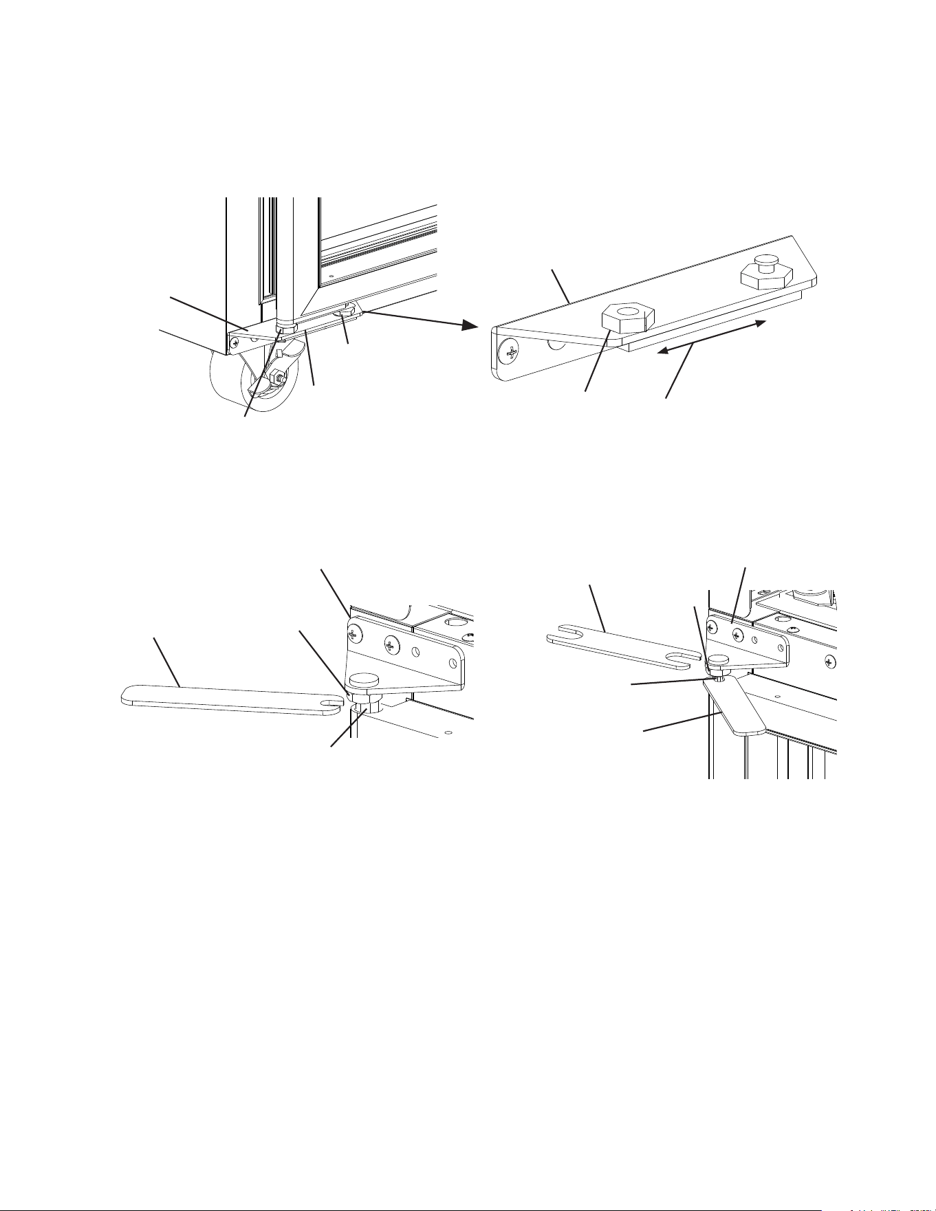
3. Full Glass Door Reversal
Special Tools and Item Required:
Wrench A: 1 - 11/16" (17 mm) Thin Open End Tappet Wrench
Wrench B: 1 - 5/16" (8 mm) Thin Open End Tappet Wrench
Loctite Thread Locker Blue 242 or 243
Note: Hoshizaki wrenches and Loctite Thread Locker Blue are available through your
local distributer.
Wrench A: 3A8298-01,
Wrench B: 3A8299-01, and
Loctite Thread Locker Blue 243: 8504-0304 (10 ml bottle).
Hinge brackets are universal and can be used in both left and right-hinged
applications.
Example shows change from right hinged to left hinged.
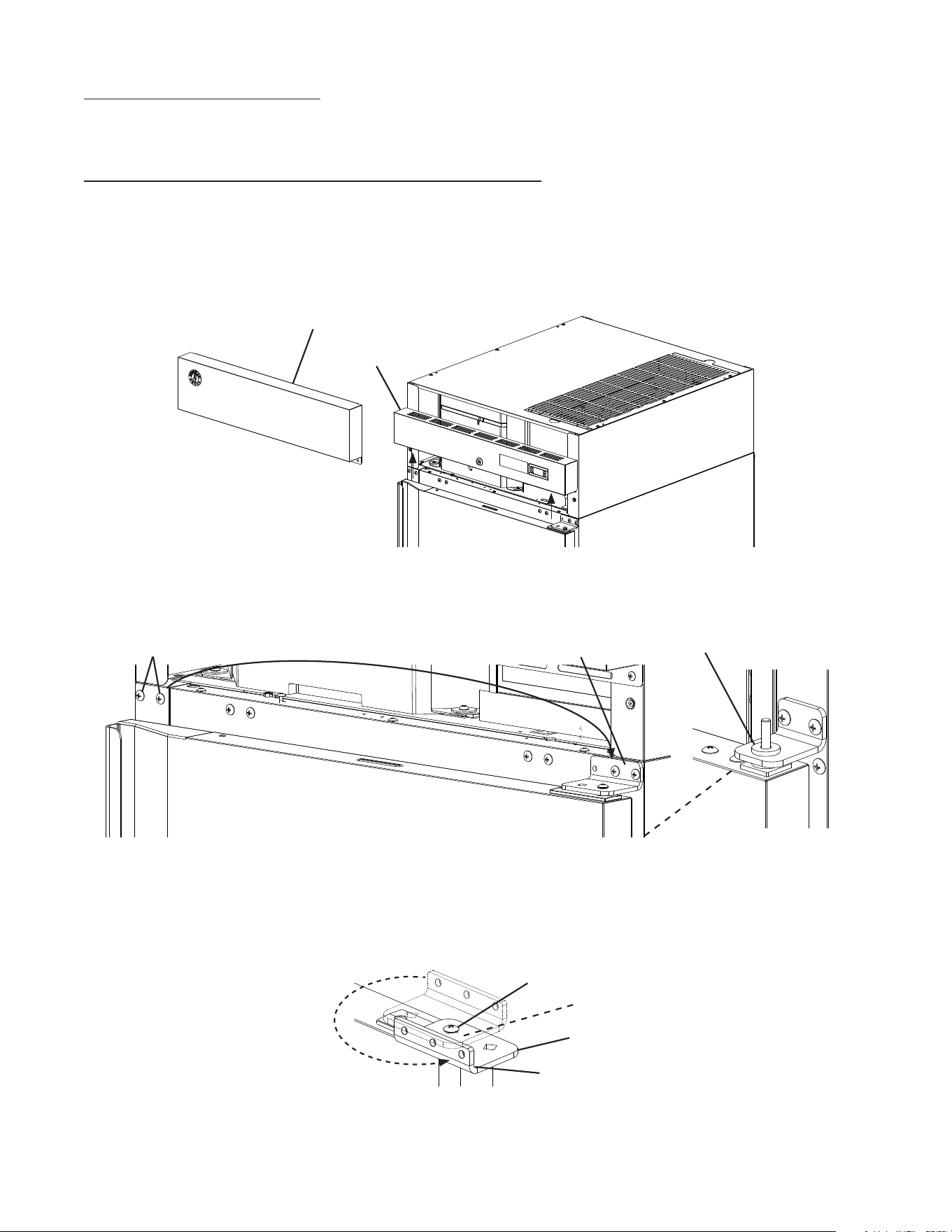
1) Lock the casters.
2) Remove the front panel, then being careful not to pull the wires on the control module
and door switch(es), remove the control panel. Secure the control panel so that it does
not interfere with the hinge bracket and will not fall. See Fig. 37.
3) At the upper hinge bracket, place wrench B on the tension rod and hold (prepare for
tension pressure), then using wrench A, loosen the lock nut. See Fig. 38.
4) Turn wrench B counter-clockwise to relieve tension on the tension rod. Without releasing
the pressure on wrench B and the tension rod, use wrench A to tighten the lock nut.
See Fig. 39.
5) Grip wrench B in a new position on the tension rod and hold (prepare for tension
pressure), then using wrenchA, loosen the lock nut again. See Fig. 40.
6) Once loose, turn wrench B counter-clockwise to relieve tension on the tension rod.
Repeat until all tension is released from the tension rod.
Fig. 40
Control Panel
Wrench A
Tension Rod
Wrench B
Tension Rod
Wrench B
Wrench A
Lock Nut
Wrench B
Wrench A
Tension Rod
Upper Hinge Bracket
30
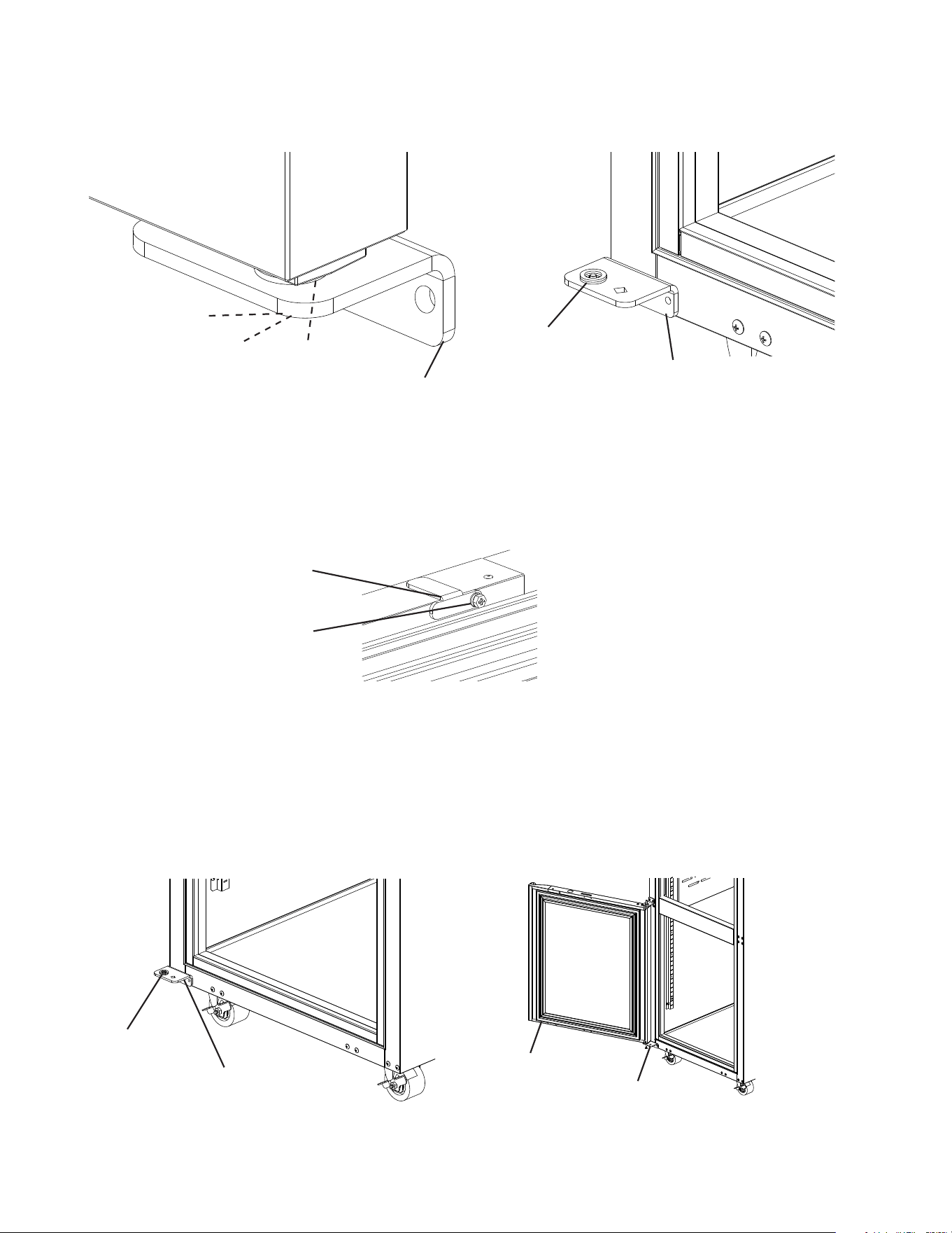
7) Open the door. Using a at head screwdriver, unhinge the lower hinge arm from the
lower hinge bracket. See Fig. 41.
11) Move the upper and lower ller screws to the opposite side of the cabinet. See Fig. 43.
NOTICE! Be sure to reuse the bracket screws for mounting the bracket as the
bracket screws are 5×12 and ller screws are 5×10.
8) Close the door, then remove the screws securing the upper hinge bracket. See Fig. 42.
9) Lift the door off the lower hinge bracket and set aside.
10) Remove the lower hinge bracket from the cabinet.
Fig. 41
Fig. 42
Fig. 43
Lower Hinge
Bracket
Lower Hinge
Bracket
Upper Hinge
Bracket
Filler Screws
Filler Screws
Lower Hinge
Arm
Lower Hinge
Arm
Lower Hinge
Bracket
31
Fig. 45
Lower Hinge
Bracket
Lower Hinge
Bracket
Slide Pin
Lower Hinge
Bracket
Bottom Hinge
Bushing
Slide Pin
Backer Plate
Apply Loctite to
Threads Here
Backer Plate
Upper Hinge Bracket
Door (Bottom)
14) Remove the upper and lower hinge brackets from the door. See Fig. 46.
13) Place and secure the new lower hinge bracket in its correct position on the cabinet.
See Fig. 45.
12) Remove the hardware from the lower hinge bracket. Apply Loctite Thread Locker Blue
242 or 243 to the bottom hinge bushing threads then place it and the slide pin in place
on the lower hinge bracket. See Fig. 44. Note: Make sure the ttings are properly
aligned, then start the connection by hand to ensure that it is not cross threaded. Just
snug the ttings, do not tighten the ttings at this time.
Fig. 44
Bottom Hinge
Bushing
Lower Hinge
Bracket
Door (Top)
Fig. 46
32
15) Rotate the door 180 degrees and place the lower hinge in its new position and secure.
See Fig. 47.
16) Place the upper hinge in its new position on the door.
17) Place the door on the lower hinge bracket in the closed position, then secure the upper
hinge bracket to the cabinet. See Fig. 48.
18) Open the door and connect the lower hinge arm to the lower hinge bracket. See Fig. 49.
Fig. 49
Fig. 48
Fig. 47
Lower Hinge
Bracket
Door (Bottom)
Upper Hinge
Bracket
Tension Rod
Door (Top)
Lower Hinge
Bracket
Upper Hinge
Bracket
Lower Hinge
Arm
Lower Hinge
Bracket
Lower Hinge
Arm
Lower Hinge
Bracket
33
22) Grip wrench B in a new position on the tension rod and hold (prepare for tension
pressure), then using wrenchA, loosen the lock nut.
23) Once loose, turn wrench B counter-clockwise to add tension on the tension rod. Without
releasing the pressure on wrench B and the tension rod, use wrench A to tighten the
lock nut.
24) Verify swing. Open the door and test the opening and closing tension. Adjust as needed
until the door opens and closes correctly.
25) Move the control panel hole plugs to the other side, then replace and secure the control
panel and front panel in their correct positions. Verify light switch and lock function and
adjust as necessary.
Fig. 50
Fig. 51
Backer Plate
Wrench B
Upper Hinge Bracket
Lower Hinge
Bracket
Lower Hinge
Arm
Slide left or right to level door
Reference Lines
Upper Hinge Bracket
21) Place wrench B on the tension rod and rotate counter-clockwise to add tension to the
tension rod. Without releasing the pressure on wrench B and the tension rod, use
wrench A to tighten the lock nut. See Fig. 51.
19) Close the door. Make sure the upper hinge bracket lock nut is loose.
20) Level the door by sliding the backer plate to the left or to the right, then tighten the slide
pin and bottom hinge bushing with a wrench until it is tight. See Fig. 50. Next, mark a
reference line on the bracket and bushing then tighten the tting an additional 1/8 turn.
Lower Hinge
Bushing
Side Pin
Lower Hinge
Bushing
Lower Hinge
Bracket
Side Pin
Backer Plate
Backer Plate
Lock Nut
Tension Rod
Wrench A
Lock Nut
Tension Rod
Wrench B
34
4. Half Glass Door Reversal
Special Tools Required:
Wrench A: 1 - 11/16" (17 mm) Thin Open End Tappet Wrench
Wrench B: 1 - 5/16" (8 mm) Thin Open End Tappet Wrench
Note: Hinge brackets are universal and can be used in both left and right-hinged
applications.
Example shows change from right hinged to left hinged.
1) Lock the casters.
2) Remove the front panel, then being careful not to pull the wires on the control module
and door switch(es), remove the control panel. Secure the control panel so that it does
not interfere with the hinge brackets and will not fall. See Fig. 52.
3) At the center hinge, place wrench B on the tension rod and hold (prepare for tension
pressure), then using wrench A, loosen the lock nut. See Fig. 53.
4) Turn wrench B counter-clockwise to relieve tension on the tension rod. Without releasing
the pressure on wrench B and the tension rod, use wrench A to tighten the lock nut.
See Fig. 54.
5) Grip wrench B in a new position on the tension rod and hold (prepare for tension
pressure), then using wrenchA, loosen the lock nut again.
6) Once loose, turn wrench B counter clockwise to relieve tension on the tension rod.
Repeat until all tension is released from the tension rod.
Fig. 54
Fig. 52
Fig. 53
Center Hinge
Bracket
Front Panel
Control Panel
Wrench B
Wrench A
Wrench A
Lock Nut
Tension Rod
Wrench B
Lock Nut
Tension Rod
Center Hinge
Bracket
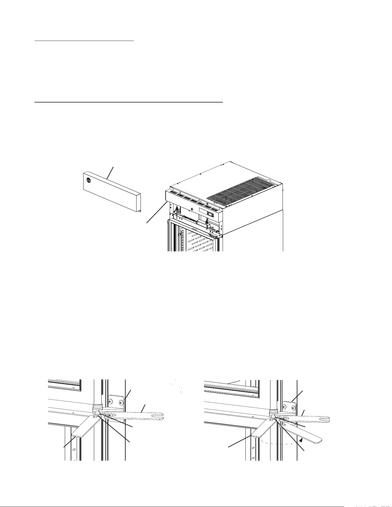
35
Fig. 55
9) Open the lower door. Using a screwdriver, unhinge the lower hinge arm from the lower
hinge bracket. See Fig. 57
Fig. 56
Fig. 57
Center Hinge
Bracket
Upper Door
Center Hinge
Bracket
Lower Hinge
Bracket
Upper Hinge
Arm
Lower Hinge
Arm
Upper Hinge
Bracket
8) Close the upper door, while maintaining a hold on the door, remove the upper hinge
bracket, then lift the door off the center hinge bracket upper pin and set aside.
See Fig. 56. Retain the upper door thrust washer and the center hinge bracket thrust
washers and washer for opposite side hinge bracket installation. NOTICE! Thrust
washers must be in place to prevent wear and damage to the hinge brackets.
7) Open the upper door. Using a at head screwdriver, unhinge the upper hinge arm from
the upper hinge bracket. See Fig. 55.
Center Hinge
Bracket
Upper Hinge
Arm
Center Hinge
Bracket
Lower Hinge
Bracket
Lower Hinge
Arm
36
10) Close the lower door. While supporting the lower door, remove the screws supporting
the center hinge bracket, then lift the lower door (with center hinge bracket) from the
lower hinge bracket and set aside. See Fig. 58.
11) Remove the lower hinge bracket, then move the ller screws for the upper, center, and
lower hinge brackets to the opposite side of the cabinet. See Fig. 59.
12) Rotate the upper hinge bracket 180 degrees, then place and secure it in the new lower
hinge bracket position. See Fig. 60. NOTICE! Be sure to reuse the bracket screws for
mounting the bracket as the bracket screws are 5×12 and ller screws are 5×10.
Lower Hinge
Bracket
Fig. 59
Lower
Door
Center Hinge
Filler Screws
Lower Hinge
Filler Screws
Lower Hinge
Bracket
Upper Hinge
Filler Screws
Fig. 58
Fig. 60
Center Hinge
Bracket
37
16) Place the now lower door onto the lower
hinge bracket in the closed position.
See Fig. 63. While supporting the lower
door, secure the center hinge bracket to the
cabinet.
17) Open the door and connect the lower hinge
arm to the slide pin, then close the door.
See Fig. 64. NOTICE! Thrust washers
must be in place to prevent wear and
damage to the hinge brackets.
Fig. 63
Fig. 64
Washer
Nut
Center Hinge
Bracket
Center Hinge
Pin
Thrust
Washer
Upper Door
Right Hinge Door
Upper Hinge
Arm
Fig. 61
Lower Hinge
Arm
Center Hinge
Bracket
Lower Hinge
Bracket
Lower Door
14) Rotate the upper door (making it the lower door) 180 degrees and place the center
hinge bracket lower pin into the top of the now lower door. See Fig. 62
15) Conrm the thrust washer is in place between the lower door and the lower hinge
bracket.
13) Remove the lock nut and tension rod from the center hinge bracket. See Fig. 61 Rotate
the center hinge bracket 180 degrees, then replace the tension rod and lock nut on the
center hinge bracket.
Fig. 62
Lower Hinge
Bracket
Center Hinge
Bracket
Lower Hinge
Bracket
Lower Door
Center Hinge Pin
Left Hinge Door
Center Hinge
Pin
Center Hinge
Bracket
Center Hinge
Pin
Center Hinge
Bracket
Washer
Thrust
Washer
Nut
38
19) While supporting the upper door and upper
hinge bracket, place the upper door onto
the upper center hinge pin on the center
hinge bracket in the closed position, then
secure the upper hinge bracket to the
cabinet. See Fig. 66. NOTICE! Be sure to
reuse the bracket screws for mounting
the bracket as the bracket screws are
5×12 and ller screws are 5×10.
18) Rotate the lower door (making it the upper door) 180 degrees. Rotate the lower hinge
bracket 180 degrees. Conrm the thrust washer is in place on the door, then place the
new upper hinge bracket onto the upper door pin. See Fig. 65.
20) Open the upper door and connect the
upper hinge arm to the slide pin on the
upper hinge bracket, then close the door.
See Fig. 67.
Fig. 65
Fig. 66
Fig. 67
Upper Hinge
Bracket
Upper Hinge
Arm
Upper Door
Upper Hinge
Bracket
Lower Hinge
Arm
Lower Door
Upper Hinge
Bracket 5×12
Mounting Screws
Upper Door
Center Hinge
Pin
Upper Hinge
Bracket
Upper Hinge
Arm
Slide Pin
39
23) Place wrench B on the tension rod and rotate counter-clockwise to add tension to the
tension rod. Without releasing the pressure on wrench B and the tension rod, use
wrench A to tighten the lock nut. See Fig. 69.
24) Grip wrench B in a new position on the tension rod and hold (prepare for tension
pressure), then using wrenchA, loosen the lock nut.
25) Once loose, turn wrench B counter-clockwise to add tension on the tension rod. Without
releasing the pressure on wrench B and the tension rod, use wrench A to tighten the
lock nut. See Fig. 70.
21) Make sure the center hinge bracket lock nut is loose.
22) Level the doors. If the doors are out of level, loosen the backer plate of the appropriate
hinge bracket, slide the backer plate to the left or to the right, then tighten the slide
pin and bottom hinge bushing with a wrench until it is tight. See Fig. 68. Next, mark a
reference line on the bracket and tting then tighten the tting an additional 1/8 turn.
Do this for both the upper and lower hinge.
26) Verify swing. Open the doors and test the opening and closing tension of each door.
Adjust as needed until the doors open and close correctly.
27) Move the control panel hole plugs to the other side, then replace and secure the control
panel and front panel in their correct positions. Verify light switch and lock function and
adjust as necessary.
Fig. 68
Fig. 69
Fig. 70
Lower Hinge
Bracket
Slide Pin
Slide Pin
Center Hinge
Bracket
Backer Plate
Bottom Hinge
Bushing
Lower Hinge
Bracket
Slide left or right to
level door
Backer Plate
Bottom Hinge
Bushing
Reference Lines
Wrench B
Wrench B
Wrench A
Wrench A
Tension Rod
Tension Rod
Lock Nut
Center Hinge
Bracket
Lock Nut
40
G. Electrical Connection
WARNING
• Electrical connection must meet national, state, and local electrical code
requirements. Failure to meet these code requirements could result in death,
electric shock, serious injury, re, or severe damage to equipment.
• This appliance requires an independent power supply of proper capacity. See
the nameplate for electrical specications. Failure to use an independent power
supply of proper capacity can result in a tripped breaker, blown fuse, damage to
existing wiring, or component failure. This could lead to heat generation or re.
• 115VAC Models: THIS APPLIANCE MUST BE GROUNDED: This appliance
is equipped with a NEMA 5-15 three-prong grounding plug to reduce the
risk of potential shock hazards. It must be plugged into a properly grounded,
independent 3-prong wall outlet. If the outlet is a 2-prong outlet, it is your personal
responsibility to have a qualied electrician replace it with a properly grounded,
independent 3-prong wall outlet. Do not remove the ground prong from the plug
and do not use an adapter plug. Failure to follow these instructions may result in
death, electric shock, or re.
• 208/230VAC Models: THIS APPLIANCE MUST BE GROUNDED: This appliance
is equipped with a NEMA L14-20 four-prong locking, grounding plug to reduce
the risk of potential shock hazards. It must be plugged into a properly grounded,
independent 4-prong wall outlet. If the outlet is a 3-prong outlet or a 4-prong
non-locking outlet, it is your personal responsibility to have a qualied electrician
replace it with a properly grounded, independent 4-prong locking wall outlet. Do
not remove the ground prong from the plug and do not use an adapter plug. After
plugging in, twist the plug clockwise to lock it into place. Failure to follow these
instructions may result in death, electric shock, or re.
• To reduce the risk of electric shock, do not touch the plug with damp hands.
• Press and hold the standby button to turn "OFF" before unplugging the appliance
to reduce the risk of electric shock.
• Do not use an extension cord.
• Do not use an appliance with a damaged power cord. The power cord should not
be altered, jerked, bundled, weighed down, pinched, or tangled. Such actions
could result in electric shock or re. To unplug the appliance, be sure to pull the
plug, not the cord, and do not jerk the cord.
• If the supply cord is damaged, it must be replaced by the manufacturer, its service
agent, or similarly qualied persons in order to avoid a hazard. Upon replacement,
the GREEN ground wire in the power cord must be connected to the designated
grounding screw.
• Usually an electrical permit and services of a licensed electrician are required.
• The maximum allowable voltage variation is ±10 percent of the nameplate rating.
41
H. Final Checklist
1) Is the appliance level?
2) Have the front casters been locked?
3) Is the appliance in a site where the ambient temperature is as specied below all year
around?
– Refrigerators and Solid Door Freezers 45°F to 100°F (7°C to 38°C)
– Glass Door Freezers 45°F to 80°F (7°C to 27°C)
4) Have the minimum clearance requirements specied below been met?
Models Side Top Rear
Reach-In Refrigerators and Freezers Except
2-Section Freezers
0" (0 cm) 0" (0 cm) 3" (8 cm)
2-Section Freezers 0" (0 cm) 10" (25 cm) 3" (8 cm)
5) Have the shipping carton, tape, and packing material been removed from the
appliance? Hasthe protective plastic lm been removed from the exterior panels on all
models and from the interior door panels on solid door models?
6) Have the appliance and accessories been checked for shipping damage?
7) Has the power supply voltage been checked or tested against the nameplate rating?
Is the power supply a properly grounded, independent wall outlet? Does the electrical
connection meet all national, state, and local code and regulation requirements.
8) Have the refrigerant lines been checked to make sure they do not rub or touch other
lines or surfaces? Has the condenser fan blade been checked to make sure it turns
freely? Is the compressor securely attached?
9) Have the shelves been properly installed?
10) Has the end user been given the instruction manual, and instructed on how to operate
the appliance and the importance of the recommended periodic maintenance?
11) Has the end user been given the name and telephone number of an authorized service
agent?
12) Has the warranty card been lled out and forwarded to the factory for warranty
registration?
42
III. Operating Instructions
R-290 Class A3 Flammable Refrigerant Used
DANGER
Risk of Fire or Explosion Flammable Refrigerant Used
• Be sure to follow all Important Safety Information located at the beginning of this
manual.
• Failure to install, operate, and maintain the appliance in accordance with this manual
will adversely affect safety, performance, component life, and warranty coverage.
• Keep clear of obstruction all ventilation openings in the appliance enclosure or in the
structure for building-in.
Risque D'Incendie ou D'Explosion. Fluide Frigorigène Inammable Utilisé.
• Veillez à respecter toutes les consignes de sécurité importantes gurant au début de
ce manuel.
• Le fait de ne pas installer, utiliser et entretenir l'appareil conformément à ce manuel
aura des conséquences négatives sur la sécurité, les performances, la durée de vie
des composants et la couverture de la garantie.
• Ne pas obstruer les ouvertures de ventilation dans l'enceinte de l'appareil ou dans la
structure d'encastrement.
A. Important Notes About Usage
WARNING
• Failure to install, operate, and maintain the appliance in accordance with this manual
may adversely affect safety, performance, component life, and warranty coverage.
• Only qualied service technicians should install and service the appliance.
• To reduce the risk of electric shock, do not touch the plug with damp hands.
• Care should be used when placing items on top of the appliance. Do not store liquid
containers or items that could fall through the louvers on top of the appliance. This
could cause electric shock or re.
• Do not use combustible spray or place volatile or ammable substances in or near the
appliance. They might catch re.
• Do not splash, pour, or spray water directly onto or into the appliance. This might cause
short circuit, electric shock, corrosion, or failure.
• Food storage and handling must comply with applicable codes and regulations.
• Keep the area around the appliance clean. Dirt, dust, or insects in the appliance could
cause harm to individuals or damage to the equipment.
• The appliance is designed only for temporary storage of food. Employ sanitary
methods. Use for any other purposes (for example, storage of chemicals or medical
supplies such as vaccine and serum) could cause deterioration of stored items.

43
WARNING continued
• Do not store items near air outlets. Otherwise, items may freeze up and crack or break
causing a risk of injury or contamination of other food.
• Do not put warm or hot foods in the cabinet. Let them cool rst, or they will raise the
cabinet temperature and could deteriorate other foods in the cabinet or overload the
appliance.
• All foods should be wrapped in plastic lm or stored in sealed containers. Otherwise
foods may dry up, pass their smells onto other foods, cause frost to develop, result in
poor appliance performance, or increase the likelihood of cross-contamination. Certain
dressings and food ingredients, if not stored in sealed containers, may accelerate
corrosion of the evaporator, resulting in failure.
• Do not block air inlets or outlets, otherwise cooling performance may be reduced.
• Do not tightly pack the cabinet. Allow some space between items to ensure good air
ow. Also allow space between items and interior surfaces.
• Do not place any product on the oor of the cabinet. All product must be placed on
properly installed shelves.
• Do not throw anything onto the shelves or load any single shelf with more than 120 lb.
(54.5 kg) of product. They might fall off and cause injury.
• Do not place more than 20 lb. (9 kg) on the top panel. Items must be stable and secure
to prevent items from falling off of the appliance.
• Open and close the doors with care. Opening the doors too quickly or forcefully may
cause injury or damage to the appliance or surrounding equipment.
• Be careful not to pinch ngers when opening and closing the doors. Be careful when
opening and closing the doors when children are in the area.
• The appliance is not intended for use by persons (including children) with reduced
physical, sensory, or mental capabilities, or lack of experience and knowledge, unless
they have been given supervision or instruction concerning use of the appliance by a
person responsible for their safety.
• Children should be properly supervised around the appliance.
• Do not climb, stand, or hang on the appliance or doors or allow children or animals to
do so. Do not climb into the appliance or allow children or animals to do so. Death or
serious injury could occur or the appliance could be damaged.
NOTICE
• Protect the oor when moving the appliance to prevent damage to the oor.
• Keep ventilation openings, in the appliance enclosure or in the built-in structure, clear
of obstruction. Blockage of airow could negatively affect performance and damage
the appliance.
• Do not allow the appliance to bear any outside weight.
• To prevent deformation or cracks, do not spray insecticide onto the plastic parts or let
them come into contact with oil.
• To avoid damage to the gasket, use only the door handle when opening and closing.
• Do not leave the doors open.
44
B. Startup
WARNING
• All parts are factory-adjusted. Improper adjustments may adversely affect safety,
performance, component life, and warranty coverage.
• To reduce the risk of electric shock, do not touch the plug with damp hands.
IMPORTANT
At startup, there is a slight delay before the compressor starts.
1) Plug the appliance into the electrical outlet. IMPORTANT! Perimeter heater, mullion
heater, and drain tube heater (drain tube heater on freezer models only), energize
once appliance is plugged into the electrical outlet and remain energized even
while the control module is in "OFF" mode. Appliance must be unplugged from
the electrical outlet to de-energize the heaters.
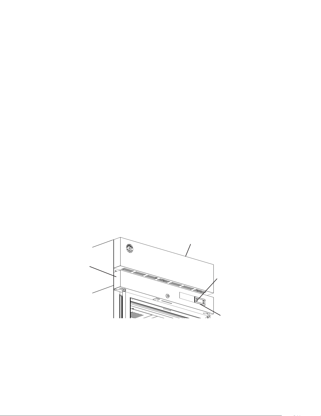
2) If the cabinet temperature is not displayed
on the control module, press and hold the
standby button on the control module until
"ON" appears in the display. See Fig. 71.
Factory default is "ON".
3) Allow the appliance to cool down prior to
loading it with food products.
Note: If the defrost thermistor is above
50°F (10°C), the evaporator fan motor is
de-energized until the defrost thermistor is
below 50°F (10°C).
C. Controls and Adjustments
1. Temperature Display
The cabinet temperature is displayed on the control module. See Fig. 72. The display
default is °F, but it can be changed to read °C. To change, see "II.C.3. Changing the
Temperature Display Scale (°F or °C)."
Control
Module
Front Panel
Fig. 71
ECO
°C
°F
V
V
Fig. 72
Up
Button
Down
Button
Front
Panel
Standby and Light Button
(glass door models)
Manual
Defrost
Button
Control Module
Compressor Icon
Defrost
Icon
Evaporator Fan
Motor Icon
Alarm
Icon
Standby Button
45
Fig. 73
Standby and Light Button for
Glass Door Models
Front Panel
Control Module
Control Panel
2. Adjusting the Temperature Setpoint
The temperature setpoint is the value for the average cabinet temperature. The
temperature differential for the compressor to turn on and off is ±3°F (±1.7°C) of the
temperature setpoint. For example, for a refrigerator temperature setpoint of 36°F (2°C),
the compressor comes on at 39°F (3.7°C), and the compressor goes off at 33°F (0.3°C).
If necessary, adjust the temperature setpoint temperature as follows:
1) To change the temperature setpoint, press and release the up or down button. The
current temperature setpoint appears. Press the up or down button until the desired
value is displayed. After a few seconds, the display returns to the current cabinet
temperature and the temperature setpoint is saved. NOTICE! Do not adjust the
temperature setpoint more than 2°F (1°C) at a time. Allow the temperature to
stabilize for a minimum of 8hours before making further temperature setpoint
adjustments.
• For refrigerators, the temperature setpoint is adjustable between 31°F and 52°F
(-0.5°C and 11°C). The factory default is 38°F (3°C).
• For freezers, the temperature setpoint is adjustable between -10°F and +12°F (-24°C
and -11°C). The factory default is -2°F (-19°C).
3. Changing the Temperature Display Scale (°F or °C)
To change the temperature display scale, press either the up or down button for 5
seconds. The factory default is °F.
4. Light Control for Glass Door Models
Glass door models feature lights that are controlled by the Standby/Light button located
on the control module. See Fig. 73. Press the standby/light button quickly to turn the light
on or off.
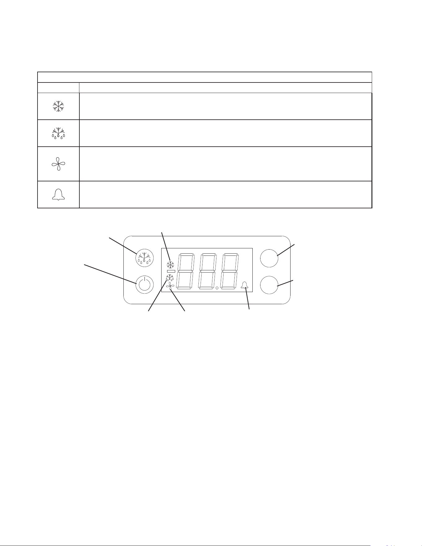
46
ECO
°C
°F
V
V
Fig. 74
Control Module
Compressor Icon
Defrost
Icon
Evaporator Fan
Motor Icon
Alarm
Icon
Standby and
Light Button (glass
door models)
Manual
Defrost
Button
Up Arrow Button
Down Arrow Button
D. Control Module Buttons and Icons
Control module icons inform you of energized components and if the appliance is in
alarm.
Control Module Icons
Icon Meaning
Compressor
Compressor running.
Defrost
Appliance is in defrost cycle. See "II.E. Defrost" for details.
Evaporator Fan Motor
Evaporator fan motor is running. Evaporator fan motor de-energizes when door is open (except
DT1A).
Alarm
Appliance is in alarm. See "II.G. Alarm Safeties" for details.

47
E. Defrost
DANGER
Risk of Fire or Explosion Flammable Refrigerant Used
• Do not use mechanical devices or other means to accelerate the defrosting
process, other than those recommended by the manufacturer.
• Do not puncture refrigerant tubing. Risk of re or explosion due to puncture of
refrigerant tubing; follow handling instructions carefully.
Risque De Feu Ou D'Explosion Le Frigorigène Est Inammable
• Ne pas utiliser d'appareils mécaniques pour dégivrer le réfrigérateur.
• Ne pas perforer la tubulure contenant le frigorigène. Risque de feu ou d'explosion si la
tubulure contenant le frigorigène est perforée; suivre les instructions de manutention
avec soin.
1. Refrigerators
Refrigerators use a time-initiated, off-cycle defrost. Defrost occurs when either the 2-hr.
cumulative compressor run timer terminates or the 2-hr. continuous compressor run timer
terminates. When either the 2-hr. cumulative compressor run timer or the
2-hr. continuous compressor run timer terminates, defrost begins. The 5-min. minimum
defrost timer and the 1-hr. maximum defrost timer starts. If energized, the compressor
de-energizes and the evaporator fan motor continues. Cabinet temperature is not
displayed during defrost; "dEF" is displayed in its place along with defrost icon. After
the 5-min. minimum defrost timer terminates and the defrost thermistor warms to 44°F
(6.6°C), defrost terminates. The defrost icon turns off and the compressor energizes.
"dEF" is displayed during defrost and continues for 15 min. after defrost termination.
Once the 15-min. "dEF" display timer terminates, cabinet temperature returns to the
display. Note: If the defrost thermistor is above 50°F (10°C) the evaporator fan motor
de-energizes until the defrost thermistor drops to 49°F (9°C).
2. Freezers
Freezers use a time-initiated, heated defrost. Defrost occurs when either the 5-hr.
cumulative compressor run timer terminates or the 4-hr. continuous compressor run timer
terminates. When either the 5 hr. cumulative compressor run timer or the 4-hr. continuous
run timer terminates, defrost begins. The 5-min. minimum defrost timer and the 1-hr.
maximum defrost timer starts. If energized, the compressor and evaporator fan motor
de-energizes. Cabinet temperature is not displayed during defrost; "dEF" is displayed in
its place along with the defrost icon. After the 5-min. minimum defrost timer terminates
and the defrost thermistor warms to 77°F (25°C), defrost terminates (defrost heater de-
energizes). A 3-min. compressor delay timer starts. Once the 3-min. compressor delay
timer terminates, the compressor energizes and a 4-min. evaporator fan motor delay
timer (drip time) starts. Once the 4-min. evaporator fan motor delay timer (drip time)
terminates, the evaporator fan motor energizes, the defrost icon turns off, and the 15-min.
temperature display delay timer starts. Once the 15-min. temperature display delay timer
terminates, cabinet temperature is displayed. Note that the 4-min. evaporator fan motor
delay time is a maximum; if the defrost thermistor cools to 15°F (-9.5°C) before the 4-min.
evaporator fan motor delay timer terminates, the evaporator fan motor will energize. Note:
If the defrost thermistor is above 32°F (0°C) the evaporator fan motor de-energizes until
the defrost thermistor drops to 29°F (-0.5°C).
3. Manual Defrost
To initiate a manual defrost, press the manual defrost button, defrost begins.

48
F. Food Storage
WARNING
• This appliance is designed only for storage of food. Employ sanitary methods. Use
for any other purposes (for example, storage of chemicals or medical supplies
such as vaccine and serum) could cause deterioration of stored items.
• Do not block the cabinet air inlet or outlet, otherwise cooling performance may be
reduced.
• Do not tightly pack the cabinet. Allow some space between items to ensure good
air ow. Also allow space between items and interior surfaces.
• Do not place any product on the oor of the cabinet. All product must be placed on
properly installed shelves.
• Do not put warm or hot foods in the cabinet. Let them cool rst, or they will raise
the cabinet temperature and could deteriorate other foods in the cabinet or
overload the appliance.
• All foods should be wrapped in plastic lm or stored in sealed containers.
Otherwise foods may dry up, pass their smells onto other foods, cause frost
to develop, result in poor appliance performance, or increase the likelihood of
cross-contamination. Certain dressings and food ingredients, if not stored in
sealed containers, may accelerate corrosion of the evaporator, resulting in failure.
• Do not store items near the air outlet. They might freeze up and crack or break
causing a risk of injury or contamination of other food.

49
G. Alarm Safeties
Alarm signals are designed to protect the appliance and food product. These alarms
give information or warnings in the event the appliance is operating out of acceptable
parameters. Should one of the alarms occur, follow the instructions in the table below to
address the alarm. The alarm code and alarm icon ash with audible alarm.
Alarm Signals
Alarm Code Problem Corrective Action/Reset Details
dor
Door Switch Alarm: Door has remained
open for more than 2 minutes.
Door Is Open or The Door Switch has
failed.
If obvious corrections such as closing doors does not
correct the alarm, call a qualied service technician.
Beeps for 10 seconds, then silent for 50 seconds.
To silence the alarm, press and release the up
button.
E01
Cabinet Thermistor Malfunction Alarm
Cabinet thermistor has failed.
Call a qualied service technician.
Beeps for 10 seconds, then silent for 50 seconds. To
silence the alarm, press and release the up button.
Appliance cycles 5 min. on, 5 min. off.
E02
Defrost Thermistor Malfunction Alarm
Defrost thermistor has failed.
Call a qualied service technician.
Beeps for 10 seconds, then silent for 50 seconds. To
silence the alarm, press and release the up button.
Appliance cycles on and off with cabinet thermistor.
Hi
High Temperature Alarm
Refrigerator: Cabinet temperature has
remained above 57°F (13.9°C) for more
than 2hours.
Freezer: Cabinet temperature has
remained above 26°F (-3.3°C) for more
than 2hours.
If obvious corrections such as closing doors and
cleaning the air lter and/or condenser do not bring
temperature back in range, call a qualied service
technician.
Beeps for 10 seconds, then silent for 50 seconds.
To silence the alarm and clear "Hi" from the display,
press and release the up button. The alarm icon
stays on.
Automatically resets when temperature returns to
normal.
Lo
Low Temperature Alarm
Refrigerator: Cabinet temperature has
remained below 26°F (-3.3°C) for more
than 2hours.
Freezer: Cabinet temperature has
remained below -23°F (-30.6°C) for more
than 2hours.
If obvious corrections do not bring the temperature
back in range, call a qualied service technician.
Beeps for 10 seconds, then silent for 50 seconds.
To silence the alarm and clear "Lo" from the display,
press and release the up button. The alarm icon
stays on.
Automatically resets when temperature returns to
normal.

50
H. Safety Devices
1. Compressor External or Internal Overload
If combined temperature/amperage value is above the limit specied by the
compressor manufacturer, the compressor overload operates independently to turn
off the compressor. The compressor overload de-energizes the compressor until the
temperature/amperage value returns to an acceptable level.
2. Short-Cycle Protection
There is a 2-minute minimum off-time and on-time for the compressor.
Note: Time may vary with compressor overload or high-pressure switch activation.
3. High-Pressure Switch
If pressure on the high-side of the appliance exceeds Hoshizaki specications, the
high-pressure switch activates and interrupts the compressor circuit, de-energizing the
compressor until the pressure returns to an acceptable level.
I. Cooling Performance
Be sure the appliance is properly installed and located for optimum cooling performance.
If cooling performance is not at its optimum level, check the following items:
• Door(s) opened too often.
• Door(s) left open. Close.
• Dirty air lter and/or condenser. Clean.
• Cabinet too tightly packed or cabinet air inlet/outlet blocked. Allow some space between
items to ensure good air ow.
• Warm or hot foods inside. Take them out until they cool down more.
• Ambient temperature too high. Avoid installation near high heat producing equipment or
exposure to direct sunlight.
• Temperature setpoint too high. Readjust it to a lower temperature.
• Appliance in defrost cycle. The cabinet temperature may rise temporarily during the
defrost cycle, but this will not affect the food inside.
J. Cabinet Condensation
In the event condensation develops on the cabinet exterior, check the following items:
• Door(s) left open. Close.
• Ambient humidity too high. In high humidity areas it may be necessary to wipe off the
cabinet frame occasionally.
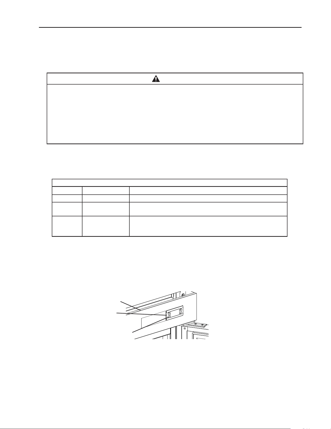
51
IV. Maintenance
This appliance must be maintained in accordance with the instruction manual and
labels provided with the appliance. Consult with your local Hoshizaki Certied Service
Representative about maintenance service. To obtain the name and phone number of
your local Hoshizaki Certied Service Representative, visit www.hoshizakiamerica.com.
WARNING
• Only qualied service technicians should service the appliance.
• Before starting a maintenance procedure, press and hold the standby button to turn
"OFF" the appliance, unplug the appliance to prevent electric shock by unexpected
entrance of water into the appliance or injury by moving parts. To reduce the risk of
electric shock, do not touch the plug with damp hands.
• Before cleaning the appliance, move all foods into another clean refrigerator or
freezer.
A. Maintenance Schedule
The maintenance schedule below is a guideline. More frequent maintenance may be
required depending on the appliance's environment, and local sanitation regulations.
Maintenance Schedule
Frequency Area Task
Bi-Weekly Air Filters Inspect. Wash with warm water and neutral cleaner if dirty.
Bi-Yearly Condenser Inspect. Clean if necessary by using a brush or vacuum cleaner.
More frequent cleaning may be required depending on location.
Annually Condenser Wick The condenser wick must be cleaned at least once a year. More
frequent cleaning may be required in some conditions to maintain
proper ow.
Control
Module
Front Panel
Fig. 75
Standby Button

52
B. Cleaning Instructions
WARNING
• Before cleaning the appliance, press and hold the standby button to turn "OFF"
the appliance, unplug the appliance to prevent electric shock by unexpected
entrance of water into the appliance or injury by moving parts. To reduce the risk
of electric shock, do not touch the plug with damp hands.
• Before cleaning the appliance, move all foods into another clean refrigerator or
freezer.
• Do not splash, pour, or spray water directly onto or into the appliance. This might
cause short circuit, electric shock, corrosion, or failure.
• Carefully follow instructions provided with cleaning and sanitizing products.
NOTICE
• To prevent damage to the plastic surfaces, do not use the following: hot water,
thinner, benzine, alcohol, petroleum, soap powder, polishing powder, alkaline
cleaner, acid, scouring pad and especially those strong cleaners for use on a
ventilating fan or a cooking range.
• To prevent corrosion and damage to stainless steel surfaces, use only products
formulated for use on stainless steel appliances. Do not use steel wool, abrasive
products, or products containing sodium hypochlorite (chlorine bleach).
• Use a clean cloth for cleaning.
1. Air Filter
Check the air lter at least twice a month. When clogged, use warm water and a neutral
cleaner to wash the lter.
2. Exterior
Wipe the exterior occasionally with a clean, soft cloth. Use a damp cloth containing
a neutral cleaner to wipe off oil or dirt buildup. Clean any rust colored spots using a
non-abrasive cleanser.
3. Cabinet Interior
Spills should be wiped up promptly to avoid unpleasant odors. The cabinet interior should
be cleaned periodically with a mild soap or detergent and warm water. NOTICE! Do not
use hot water to clean the cabinet interior.
4. Door Gaskets
Door gaskets should be cleaned regularly with mild soap and warm water to remove dirt
and grease.
5. Shelves
Remove and clean regularly.
6. Glass Door
Wipe occasionally with a clean, soft cloth. Use a damp cloth containing a neutral cleaner
to wipe off oil or dirt buildup.
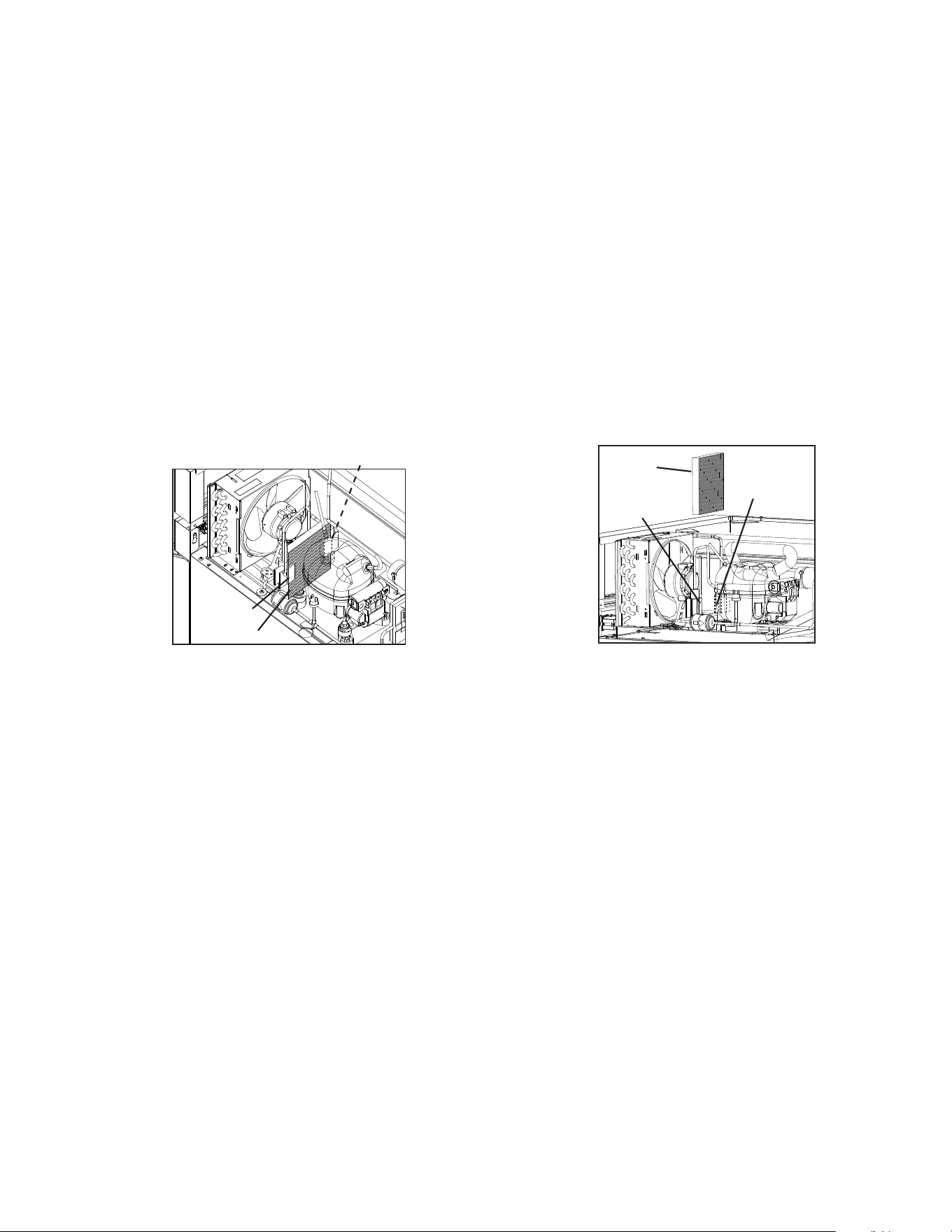
53
Fig. 76
Wick
Retainer
Retainer
Retainer
Retainer
Wick
7. Condenser
The condenser must be cleaned at least once a year. More frequent cleaning may be
required in some conditions. Use a brush or vacuum cleaner to clean the condenser as
required.
8. Condensate Wick (Except DT1A-HS and Freezer on DT2A-FS)
The condensate wick must be cleaned at least once a year. More frequent cleaning may
be required in some conditions to maintain proper ow. Follow the steps below.
1) Unplug the appliance from the electrical outlet. WARNING! To reduce the risk of
electric shock, do not touch the plug with damp hands.
2) Remove the wick from the retainers. See Fig. 76.
3) Clean or replace the wick. NOTICE! If the wick is clogged/deteriorating replace.
4) Replace the wick in its correct position.
NOTICE! Be sure the wick is positioned into the condensate pan.
5) Plug the appliance back in.
9. Power Supply Connection
If the plug or power cord is damaged, contact your local Hoshizaki service representative
or local Hoshizaki distributor immediately and ask for repairs.
All other maintenance or service on this appliance should be performed in accordance
with the Hoshizaki Service Manual by a qualied service technician.
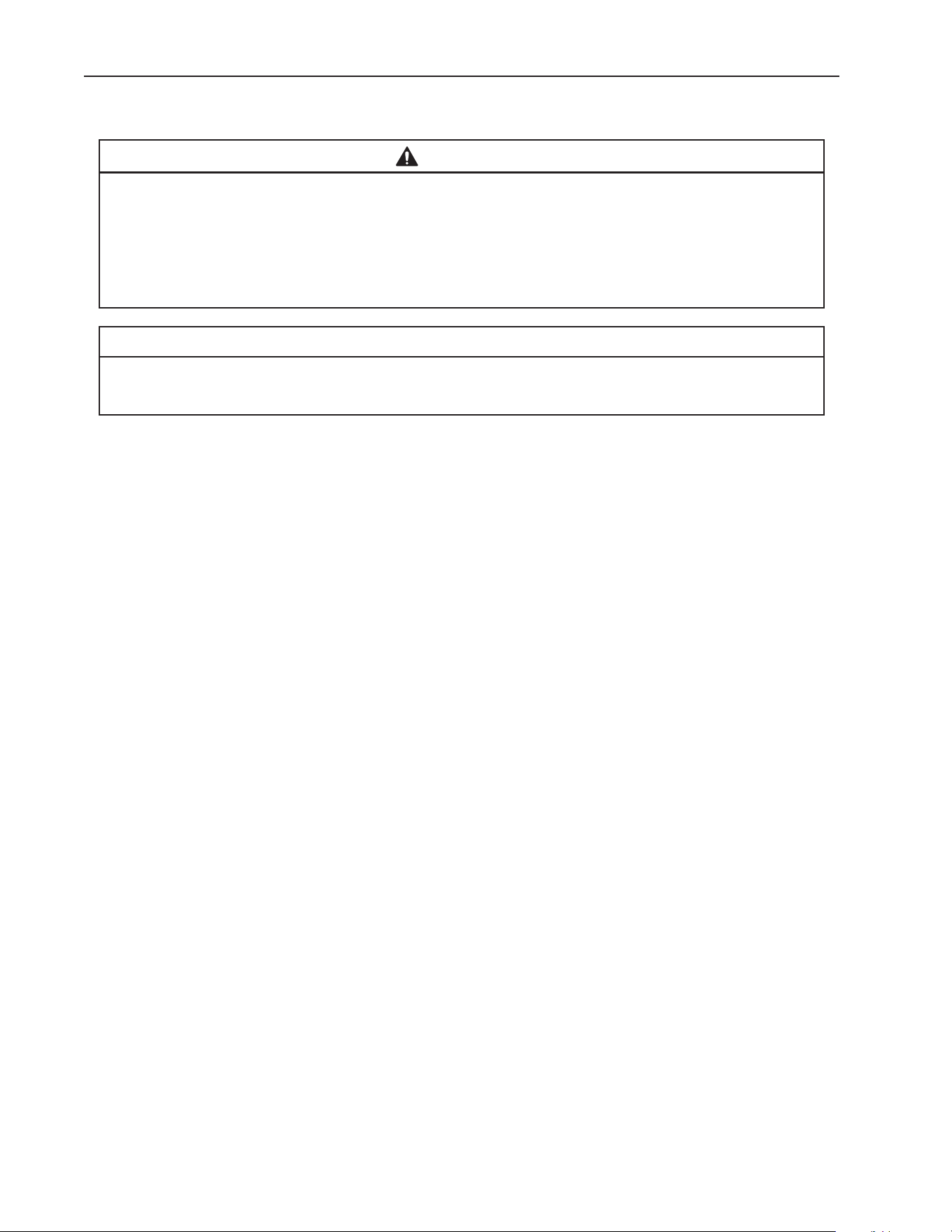
54
V. Preparing the Appliance for Periods of Non-Use
When shutting down the appliance for periods of non-use, follow the instructions below.
WARNING
• When preparing the appliance for long storage, prevent the doors or drawers from
closing to reduce the risk of children getting trapped.
• Risk of electric shock. Appliance in the off position does not de-energize all loads.
Use extreme caution and exercise safe electrical practices.
• To reduce the risk of electric shock, do not touch the plug with damp hands.
NOTICE
When preparing the appliance for long storage, clean the appliance. See "III.A.
Cleaning" for details.
1) Before shutting down the appliance, move the stored food into another refrigerator or
freezer.
2) Press and hold the standby button on the control module until "OFF" appears in the
display, then unplug the appliance from the electrical outlet. See Fig. 76.
IMPORTANT! Perimeter heater, mullion heater, and drain tube heater (drain tube
heater on freezer models only), energize once appliance is plugged into the
electrical outlet and remain energized even while the control module is in "OFF"
mode. Unplug the appliance from the electrical outlet to de-energize the heaters.

VI. Decommissioning and Disposal
R-290 Class A3 Flammable Refrigerant Used
DANGER
Risk of Fire or Explosion Flammable Refrigerant Used
• Only qualied service technicians should install and service the appliance.
• Follow handling instructions carefully in compliance with national regulations.
• Dispose of properly in accordance with federal or local regulations.
• Do not puncture refrigerant tubing. Risk of re or explosion due to puncture of
refrigerant tubing; follow handling instructions carefully.
• Be sure to follow the full Decommissioning and Disposal information located in the
Service Manual for this model. The Service Manual is available at
www.hoshizakiamerica.com.
Risque D'Incendie ou D'Explosion. Fluide Frigorigène Inammable Utilisé
• Seuls des techniciens de service qualiés doivent installer et entretenir l'appareil.
• Suivre attentivement les instructions de manutention conformément aux réglements
nationaux.
• Mettre au rebut conformément aux conformément aux réglements fédéraux ou
locaux.
• Ne pas perforer la conduite de uide frigorigène. Risque d'incendie ou d'explosion
en cas de perforation d'une canalisation de uide frigorigène; suivez attentivement
les instructions de manutention.
• Veiller à respecter l'ensemble des informations relatives à la mise hors service et
à la mise au rebut gurant dans le manuel d'entretien de ce modèle. Le manuel
d'entretien est disponible à l'adresse suivante: www.hoshizakiamerica.com.

618 Hwy. 74 South, Peachtree City, GA 30269 USA (P) 770.487.2331 (F) 770.487.3360 hoshizakiamerica.com 1A8261-010