AVPTC**14**
© 2018-2020 Goodman Manufacturing Company, L.P.
19001 Kermier Rd., Waller, TX 77484
www.goodmanmfg.com - or - www.amana-hac.com
P/N: IOA-4030B Date: March 2020
AIR HANDLERS
INSTALLATION & OPERATING INSTRUCTIONS
is a registered trademark of Maytag Corporaon or its related companies and is used under license. All rights reserved.
ATTENTION INSTALLING PERSONNEL
Prior to installaon, thoroughly familiarize yourself with this Instal-
laon Manual. Observe all safety warnings. During installaon or
repair, cauon is to be observed. It is your responsibility to install the
product safely and to educate the customer on its safe use.
Contents
1 Important Safety Instructions .................................... 2
2 Shipping Inspection ................................................... 3
3 Codes & Regulations .................................................. 3
4 Replacement Parts ..................................................... 3
5 Pre-Installation Considerations ................................. 3
6 Installation Location ................................................... 3
7 Refrigerant Lines ........................................................ 5
8 Condensate Drain Lines ............................................. 8
9 Ductwork ..................................................................... 9
10 Return Air Filters ......................................................... 9
11 Achieving1.4%and2.0%AirowLow
Leakage Rate ............................................................... 9
12 Electric Heat ................................................................ 9
13 Electrical and Control Wiring................................... 10
14 AVPTC Motor Orientation ......................................... 11
15 Cool Cloud HVAC Phone Application ...................... 11
16 Quick Start Guide for Communicating
Outdoor Units ............................................................ 12
17 Quick Start Guide for Non-Communicating
Outdoor Units ............................................................ 12
18 Dehumidication ....................................................... 14
19 Auxiliary Alarm Switch ............................................ 14
20 Start-Up Procedure ................................................... 14
21 Accessories ............................................................... 14
22 RampingProles ...................................................... 15
23 Electric Air Cleaner Warning.................................... 15
24 Start-Up Procedure ................................................... 16
25 Regular Maintenance ................................................ 16
26 Air Handler Troubleshooting Matrix ........................ 17
27 Air Handler Display .................................................. 19
28 AirowLabel ............................................................ 22
29 Wiring Diagram ........................................................ 23
RECOGNIZE THIS SYMBOL AS A
SAFETY PRECAUTION.
Only personnel that have been trained to install, adjust, ser-
viceorrepair(hereinafter,“service”)theequipmentspecied
in this manual should service the equipment. The manufac-
turer will not be responsible for any injury or property dam-
age arising from improper service or servide procedures.
If you service this unit, you assume responsibility for any
injury or property damage which may result. In addition, in
jurisdictions that require one or more licenses to service the
equipmentspeciedinthismanual,onlylicensedpersonnel
should servise the equipment.
Improper installation, adjustment, servicing or repair of the
equipmentspeciedinthismanual,orattemptingtoinstall,
adjust,serviceorrepairtheequipmentspeciedinthis
manual without proper training may result in product dam-
age, property damage, personal injury or death.
WARNING
-
www.P65Warnings.ca.gov
PROP 65 WARNING
FOR CALIFORNIA CONSUMERS
0140M00517-A
WARN ING
This device, which was assembled by Goodman Manufacturing
Company, L.P., contains a component that is classied as an
intentional radiator. This intentional radiator has been certied by
the FCC: FCC ID QOQBGM111. And this international radiator has
an Industry Canada ID: IC 5123A-BGM111.
This device complies with Part 15 of the FCC’s Rules. Operation of
this device is subject to two conditions:
(1) This device may not cause harmful interference; and
(2) This device must accept any interference received, including
interference that may cause undesirable operation.
And this device meets the applicable Industry Canada technical
specications.
The manufacturer of the intentional radiator (model no. BGM111) is
Silicon Laboratories Finland Oy, which can be contacted by calling
617-951-0200. (www.silabs.com)
The FCC responsible party is Goodman Manufacturing Company,
L.P., and may be contacted by calling (713)-816-2500, or at 19001
Kermier RD., Waller TX 77484. (www.GoodmanMFG.com)
This equipment complies with FCC radiation exposure limits. To
ensure compliance, human proximity to the antenna shall not be
less the 20cm during normal operations.
2
1 ImportantSafetyInstrucons
The following symbols and labels are used throughout this man-
ual to indicate immediate or potenal safety hazards. It is the
owner’s and installer’s responsibility to read and comply with all
safety informaon and instrucons accompanying these symbols.
Failure to heed safety informaon increases the risk of personal
injury, property damage, and/or product damage.
To prevent the risk of property damage, personal
injury, or death, do not store combustible materials or
use gasoline or other flammable liquids or vapors in
the vicinity of this unit.
This product is factory-shipped for use with
208/240/1/60 electrical power supply.
reconfigure this air handler to operate with any other
power supply.
DO NOT
To avoid property damage, personal injury or death
due to electrical shock, this unit MUST have an
electrical ground. The
electrical ground circuit may consist of an
appropriately sized electrical wire connecting the
ground lug in the unit control box to the building
electrical service panel.
Other methods of grounding are permitted if performed
in accordance with the National Electric Code
(NEC)/American National Standards Institute
(ANSI)/National Fire Protection Association (NFPA) 70
and local/state codes. In Canada, electrical grounding
is to be in accordance with the Canadian Electric Code
(CSA) C22.1.
uninterrupted, unbroken
When installing or servicing this equipment, safety
clothing, including hand and eye protection, is
strongly recommended. If installing in an area that has
special safety requirements (hard hats, etc.), b serve
these requirements.
o
Do not connect to or use any device that is not design-
certified by the manufacturer for use with this unit.
Serious property damage, personal injury, reduced
unit performance and/or hazardous conditions may
result from the use of such non-approved devices.
HIGH VOLTAGE!
Failure to do so may cause property damage,
personal injury or death.
Disconnect ALL power before servicing.
Multiple power sources may be present.
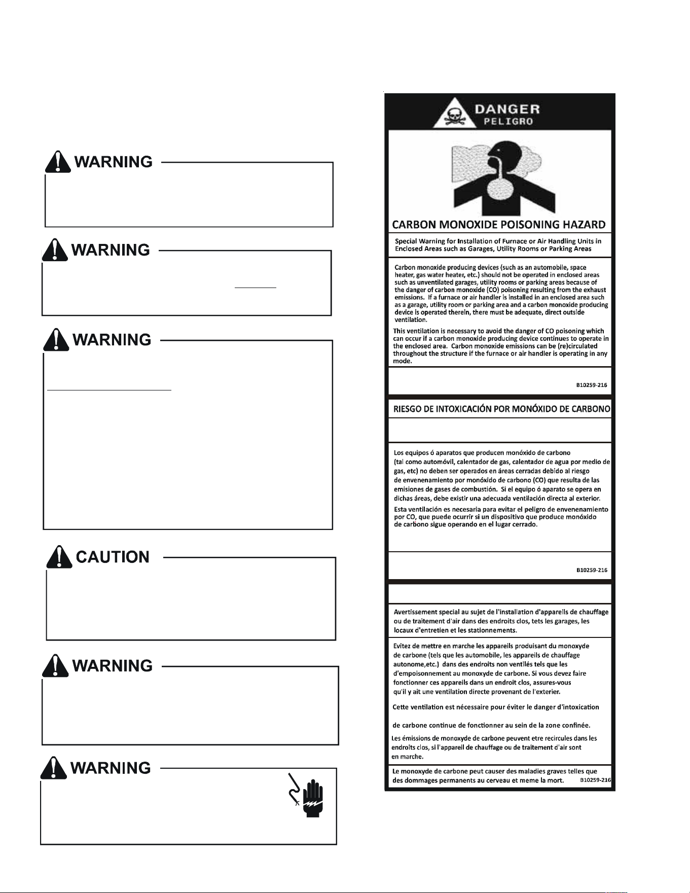
CO can cause serious illness including permanent brain
damage or death.
Advertencia especial para la instalación de calentadores ó manejadoras
de aire en áreas cerradas como estacionamientos ó cuartos de servicio.
El monóxido de carbono puede causar enfermedades severas
como daño cerebral permanente ó muerte.
Las emisiones de monóxido de carbono pueden circular a través
del aparato cuando se opera en cualquier modo.
RISQUE D'EMPOISONNEMENT AU
MONOXYDE DE CARBONE
au CO pouvant survenir si un appareil produisant du monoxyde

3
2 ShippingInspecon
Always transport the unit upright; laying the unit on its side or top
during transit may cause equipment damage. The installer should in-
spect the product upon receipt for shipping damage and subsequent
invesgaon is the responsibility of the carrier. The installer must
verify the model number, specicaons, electrical characteriscs,
and accessories are correct prior to installaon. The distributor or
manufacturer will not accept claims from dealers for transportaon
damage or installaon of incorrectly shipped units.
2.1 Parts
Also inspect the unit to verify all required components are
present and intact. Report any missing components imme-
diately to Goodman or to the distributor. Use only factory
authorized replacement parts (see Secon 5). Make sure to
include the full product model number and serial number
when reporng and/or obtaining service parts.
2.2 Handling
Use cauon when transporng/carrying the unit. Do not move
unit using shipping straps. Do not carry unit with hooks or sharp
objects. The preferred method of carrying the unit aer arrival
at the job site is to carry via a two-wheel hand truck from the
back or sides or via hand by carrying at the cabinet corners.
3 Codes&Regulaons
This product is designed and manufactured to comply with appli-
cable naonal codes. Installaon in accordance with such codes
and/or prevailing local codes/regulaons is the responsibility of the
installer. The manufacturer assumes no responsibility for equipment
installed in violaon of any codes or regulaons.
TheUnited States Environmental ProteconAgency(EPA) has
issuedvariousregulaonsregardingtheintroduconanddisposal
ofrefrigerants.Failuretofollowtheseregulaonsmayharmthe
environmentandcanleadtotheimposionofsubstanalnes.
Should you have any quesons please contact the local oce of the
EPA and/or refer to EPA’s website www.epa.gov.
4 Replacement Parts
When reporng shortages or damages, or ordering repair parts,
give the complete product model and serial numbers as stamped
on the product. Replacement parts for this product are available
through your contractor or local distributor. For the locaon of your
nearest distributor consult the white business pages, the yellow
page secon of the local telephone book or contact:
HOMEOWNER SUPPORT
GOODMAN MANUFACTURING COMPANY, L.P.
19001 KERMIER ROAD,
WALLER, TX 77484
(877) 254-4729
5 Pre-InstallaonConsideraons
5.1 Preparaon
Keep this document with the unit. Carefully read all instruc-
ons for the installaon prior to installing product. Make sure
each step or procedure is understood and any special consid-
eraons are taken into account before starng installaon.
Assemble all tools, hardware and supplies needed to complete
the installaon. Some items may need to be purchased locally.
Make sure everything needed to install the product is on hand
before starng.
5.2 System Matches
The entire system (combination of indoor and outdoor
secons) must be manufacturer approved and Air-Condi-
oning, Heang, and Refrigeraon Instute (AHRI) listed.
NOTE: Installaon of unmatched systems is not permied.
Damage or repairs due to installaon of unmatched systems
is not covered under the warranty.
5.3 InterconnecngTubing
Give special consideraon to minimize the length of refrigerant
tubing when installing air handlers. Refer to Remote Cooling/
Heat Pump Service Manual RS6200006, and TP-107 Long Line
Set Applicaon R-410A for tubing guidelines. If possible, allow
adequate length of tubing such that the coil may be removed
(for inspecon or cleaning services) from the cabinet without
disconnecng the tubing.
5.4 Clearances
The unit clearance from a combusble surface may be 0”.
However, service clearance must take precedence. A minimum
of 24” in front of the unit for service clearance is required.
Addional clearance on one side or top will be required for
electrical wiring connecons. Consult all appropriate reg-
ulatory codes prior to determining nal clearances. When
installing this unit in an area that may become wet (such as
crawl spaces), elevate the unit with a sturdy, non-porous ma-
terial. In installaons that may lead to physical damage (i.e. a
garage) it is advised to install a protecve barrier to prevent
such damage. Always install units such that a posive slope
in condensate line (1/4” per foot) is allowed.
5.5 HorizontalApplicaons
If installed above a nished living space, a secondary drain
pan (as required by many building codes), must be installed
under the enre unit and its condensate drain line must be
routed to a locaon such that the user will see the condensate
discharge.
6 InstallaonLocaon
NOTE: These air handlers are designed for indoorinstallaononly.
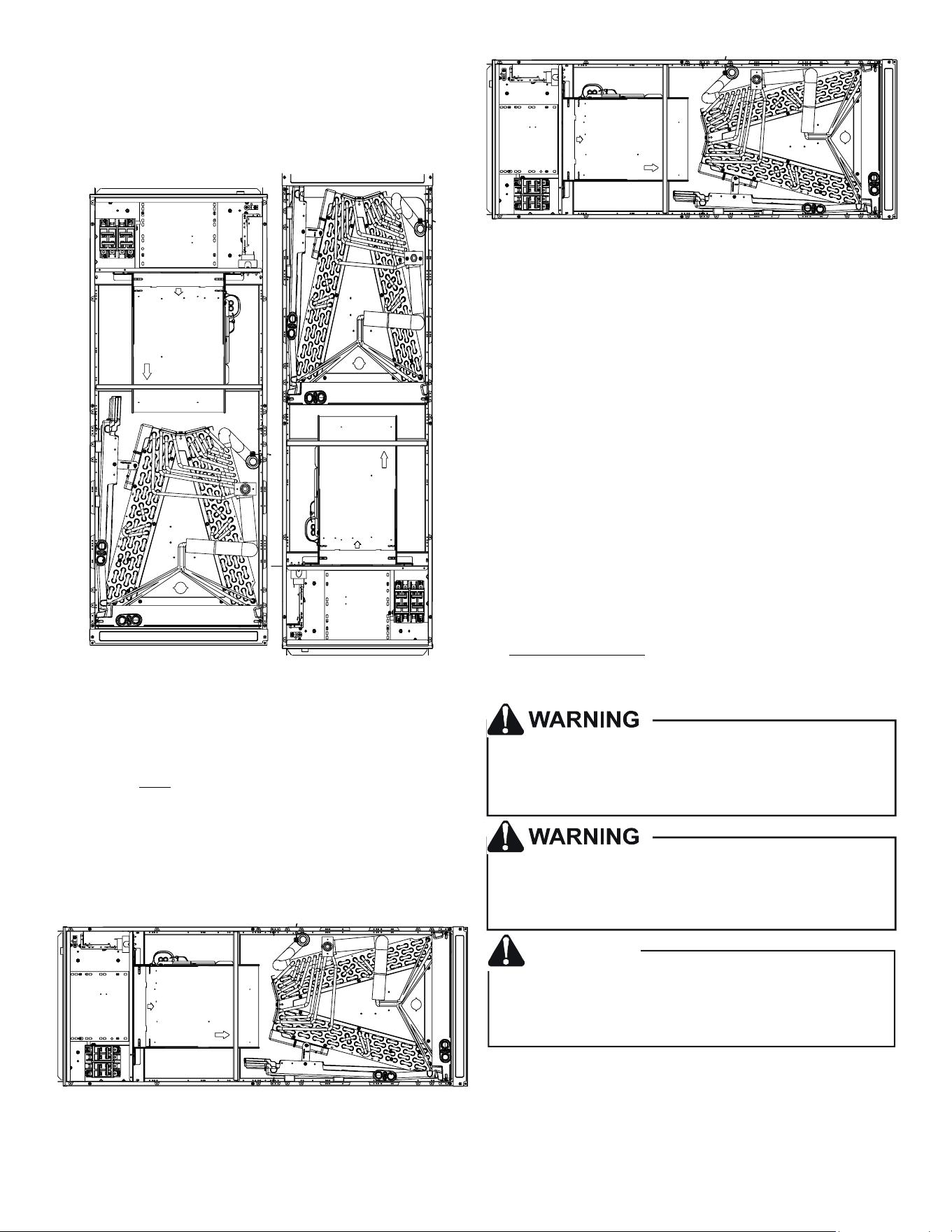
The AVPTC**14** product line may be installed in one of the up-
ow, downow, horizontal le or horizontal right orientaons as
shown in Figures 2, 3, 4 and 5. The unit may be installed in upow
or horizontal le orientaon as shipped (refer to specic secons
for more informaon).
Minor eld modicaons are necessary to convert to downow
or horizontal right as indicated in below secons.
4
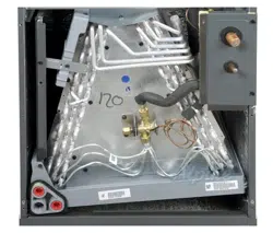
6.1 UpowInstallaon
No eld modicaons are mandatory; however, to obtain
maximum eciency, the horizontal drip shield, side drain pan
and drain pan extension can be removed.
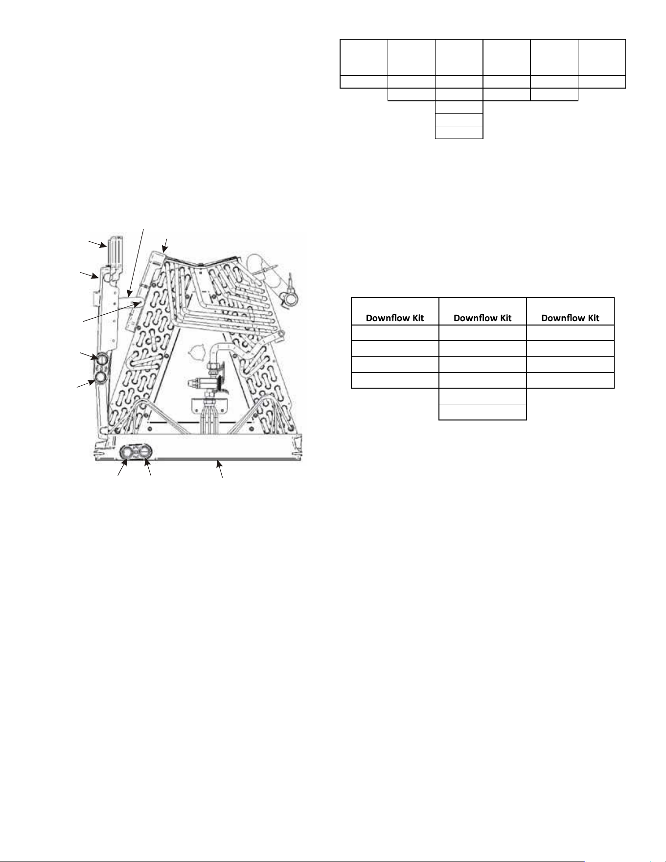
Side Drain Pan and Extension Removal: Refer to Figure 1, re-
move the two (2) screws that secure the drip shield support
brackets to the condensate collectors (front and back). Unsnap
the side drain pan from the main drain pan using a screw driver
or any small lever. The side drain pan, drip shield brackets and
the drain pan extension may now be removed. From Figure 1,
drain port labeled (A) is the primary drain for this applicaon
and condensate drain line must be aached to this drain port.
Drain port (a) is for the secondary drain line (if used).
Drip Pan
Extension
Side
Drain
Pan
Screw
B
b
A
Main Drain Pan
Drip Shield Bracket
Drip Shield
Pna
SIDE DRAIN PAN REMOVAL
Figure 1
6.2 HorizontalLeInstallaon
No eld modicaons are permissible for this applicaon.
The boom right drain connecon is the primary drain for
this applicaon and condensate drain line must be aached
to this drain connecon. The top connecon of the three
drain connecons on the drain pan must remain plugged for
this applicaon. The boom le drain connecon is for the
secondary drain line (if used).
In applicaons where the air handler is installed in the horizon-
tal le posion, and the return air environment see humidity
levels above 65% relave humidity coupled with total external
stac levels above 0.5” e.s.p., a condensate kit is available for
eld applicaon. Kit nomenclature can be found in Table 1.
CMK000 8
Condensate
Kit
CMK000 9
Condensa te
Kit
CMK001 0
Condensate
Kit
CMK0012
Condensa te
Kit
CMK001 3
Condensate
Kit
CMK001 4
Condensa te
Kit
AVPTC25B14 AVPTC29B14 AVPTC31C14 AVPTC49D14 AVPTC33C14 AVPTC49C14
AVPTC37B14 AVPTC37C14 AVPTC61D14 AVPTC39C14
AVPTC37D14
AVPTC59C14
AVPTC59D14
CONDENSATE KIT
TABLE 1
6.3 Downow/HorizontalRightInstallaon
IMPORTANT NOTE: In the downow applicaon, to prevent
coil pan “sweang”, a downow kit (DFK) is available through
your local Goodman distributor. The DFK is not supplied with
the air handler and is required by Goodman on all downow
installaons. See Table 2 for the correct DFK and follow the
instrucons provided for installaon.
DFK-B DFK-C DFK-D
AVPTC25B14** AVPTC31C14** AVPTC37D14**
AVPTC29B14** AVPTC37C14** AVPTC49D14**
AVPTC35B14** AVPTC59C14** AVPTC59D14**
AVPTC37B14** AVPTC33C14** AVPTC61D14**
AVPTC39C14**
AVPTC49C14**
MODEL LIST FOR DOWNFLOW KITS
DOWNFLOW KIT
TABLE 2
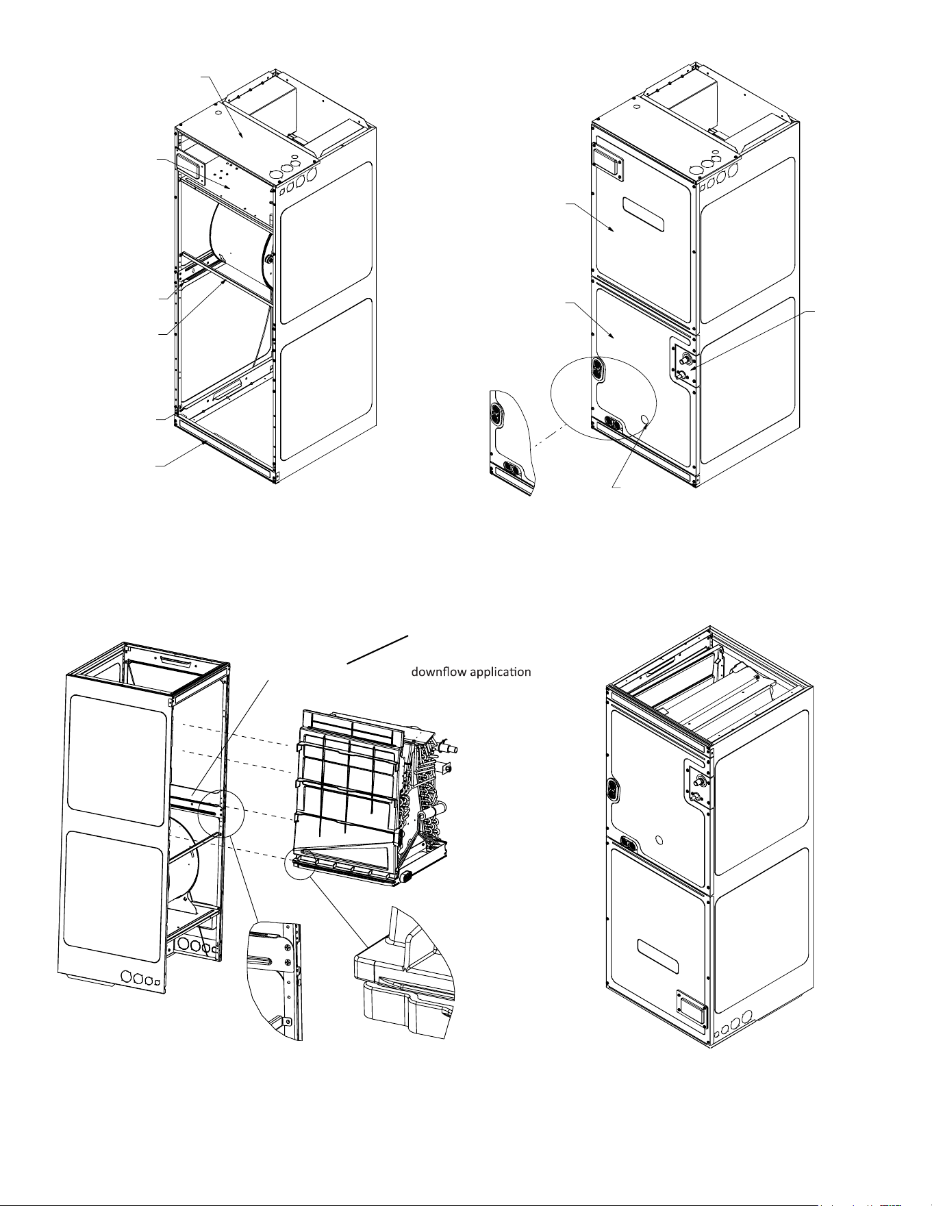
Refer to Figure 6 and 7 for the locaon of the components
referenced in the following steps.
1. Before inverng the air handler, remove blower access
panel and coil access panel. The coil access panel and
tubing panel may remain screwed together during this pro-
cedure. Remove and retain the seven (7) screws securing
the coil access panel to the cabinet and the six (6) screws
securing the blower access panel to the cabinet.
2. Slide the coil assembly out using the drain pan to pull the
assembly from the cabinet.
NOTE: DO NOT USE MANIFOLDS OR FLOWRATOR TO
PULL THE COIL ASSEMBLY OUT. FAILURE TO DO SO MAY
RESULT IN BRAZE JOINT DAMAGE AND LEAKS.
3. Removal of the center support is required on units with
21” wide cabinet. Remove and retain the two (2) screws
that secure the center support to the cabinet. Remove the
center support.
4. Using the drain pan to hold the coil assembly, slide the coil
assembly back into the cabinet on the downow brackets
as shown in Figure 8.
5. Re-install the center support (if removed) using the two (2)
screws removed in Step 4.
6. Re-install the access panels removed in Step 1 as shown in
Figure 9.
5
7. The boom le drain connecon is the primary drain for
this applicaon and condensate drain line must be aached
to this drain connecon. The top connecon of the three
drain connecons on the drain pan must remain plugged
for this applicaon. The boom le drain connecon is for
the secondary drain line (if used).
UPFLOW DOWFLOW
UPFLOW DOWFLOW
Figure 2 Figure 3
NOTE: If removing only the coil access panel from the unit, the lter
access panel must be removed rst. Failure to do so may result in
panel damage.
Do not install the air handler in a location that violates the
instrucons provided with the condenser. If the unit is located in
an uncondioned area with high ambient temperature and/or high
humidity, the air handler may be subject to nuisance sweang of
the casing. On these installaons, a wrap of 2” berglass insulaon
with a vapor barrier is recommended.
HORIZONTAL LEFT
Figure 4
HORIZONTAL RIGHT
Figure 5
7 Refrigerant Lines
NOTE: Refrigerant tubing must be routed to allow adequate access
for servicing and maintenance of the unit.
7.1 TubingSize
For the correct tubing size, follow the specicaon for the
condenser/heat pump.
7.2 TubingPreparaon
All cut ends are to be round, burr free, and clean. Failure to
follow this pracce increases the chances for refrigerant leaks.
The sucon line is spun closed and requires tubing cuers to
remove the closed end.
NOTE: To prevent possible damage to the tubing joints, do not
handle coil assembly with manifold or owrator tubes. Always
use clean gloves when handling coil assemblies.
NOTE: The use of a heat shield is strongly recommended when
brazing to avoid burning the serial plate or the nish of the unit.
Heat trap or wet rags must be used to protect heat sensive
components such as service valves and TXV valves sensing bulb.
This product is factory-shipped with R410A and dry
nitrogen mixture gas under pressure. Use appropriate
service tools and follow these instructions to prevent
injury.
A quenching cloth is strongly recommended to prevent
scorching or marring of the equipment finish when
brazing close to the painted surfaces. Use brazing
alloy of 5% minimum silver content.
Applying too much heat to any tube can melt the tube. Torch
heat required to braze tubes of various sizes must be
proportional to the size of the tube. Service personnel must
use the appropriate heat level for the size of the tube being
brazed.
CAUTION
6
EXTERNAL PART TERMINOLOGY
Figure 7
INTERNAL PART TERMINOLOGY
Figure 6
IMPORTANT NOTE:
Ensure coil slides on the rails along the groove provided on the drain pan side walls. Failure
to do so will result in improper condensate drainage.
COIL INSTALLATION FOR DOWNFLOW
Figure 8
Upper Tie Plate
Control
Deck
Downflow
Bracket
Center
Support
Filter
Bracket
Filter
Access
Panel
ACCESS PANEL CONFIGURATION
FOR DOWNFLOW OR HORIZONTAL RIGHT
Figure 9
Blower
Access
Panel
Coil
Access
Panel
Tubing
Panel
UV
Knockout
Coil Slides
on the downflow bracket
Remove side drain pan
extension for
7
7.3 TubingConneconsforTXVModels
TXV models come with factory installed TXV with the bulb
pre-installed on the vapor tube.
1. Remove refrigerant tubing panel or coil (lower) access pan-
el.
2. Remove access valve ng cap and depress the valve stem
in access ng to release pressure. No pressure indicates
possible leak.
3. Replace the refrigerant tubing panel.
4. Remove the spin closure on both the liquid and sucon
tubes using a tubing cuer.
5. Insert liquid line set into liquid tube expansion and slide
grommet about 18” away from braze joint.
6. Insert sucon line set into sucon tube expansion and slide
insulaon and grommet about 18” away from braze joint.
7. Braze joints. Quench all brazed joints with water or a wet
rag upon compleon of brazing.
NOTE: The sensing bulb must be permanently located. A heat
shield, heat trap, or wet rag must be used during brazing to prevent
damage to the TXV valve.
8. Replace access panels, sucon line grommet, insulaon and
all screws.
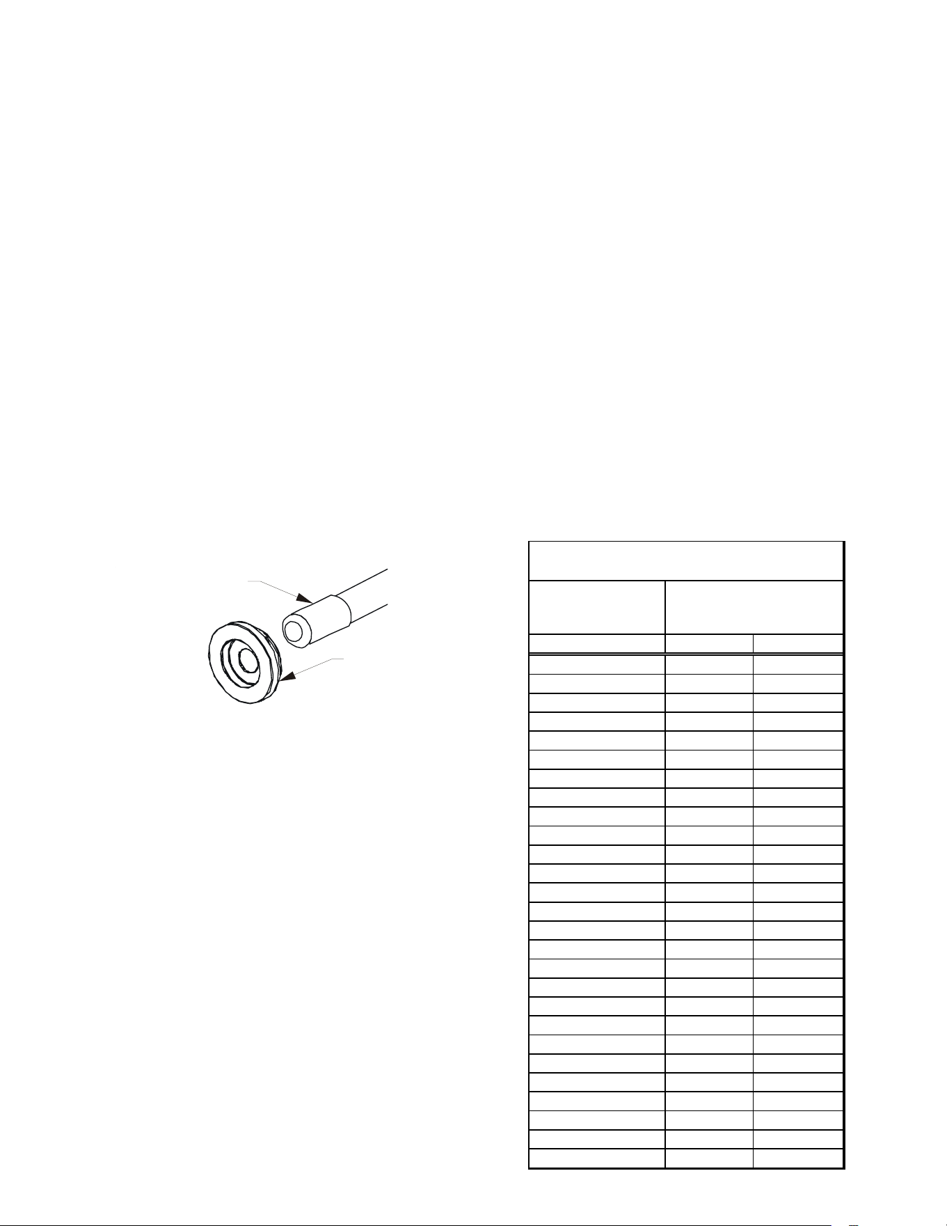
RUBBER
GROMMET
SUCTION LINE
WITH SPIN CLOSURE
SuconLineGrommet
Figure 10
7.4 ThermalExpansionValveSystemAdjustment
Run the system at Cooling for 10 minutes unl refrigerant
pressures stabilize. Use the following guidelines and meth-
ods to check unit operaon and ensure that the refrigerant
charge is within limits. Charge the unit on low stage.
1. Purge gauge lines. Connect service gauge manifold to base-
valve service ports.
2. Temporarily install a thermometer on the liquid line at the
liquid line service valve and 4-6’’ from the compressor on
the sucon line. Ensure the thermometer makes adequate
contact and is insulated for best possible readings. Use
liquid line temperace to determine subcooling and vapor
temperature to determine superheat.
3. Check subcooling and superheat. Systems with TXV applica-
on should have a subcooling of 7 to 9°F and superheat of
7 to 9°F
a. If subcooling and superheat are low, adjust TXV to 7 to
9°F, and then check subcooling.
NOTE: To adjust superheat, turn the valve stem clockwise to in-
crease and counter clockwise to decrease.
b. If subcooling is low and superheat is high, add charge to
raise subcooling to 7 to 9°F, and then check superheat.
c. If subcooling and superheat are high, adjust TXV valve to
7 to 9° superheat, then check subcooling.
d. If subcooling is high and superheat is low, adjust TXV valve
to 7 to 9° superheat and remove charge to lower the sub-
cooling to 7 to 9°F.
NOTE: Do NOT adjust the charge based on sucon pressure unless
there is a gross undercharge.
4. Disconnect manifold set, and installaon is complete.
NOTE: Check the Schrader ports for leaks and ghten valve cores
if necessary. Install caps nger-ght.
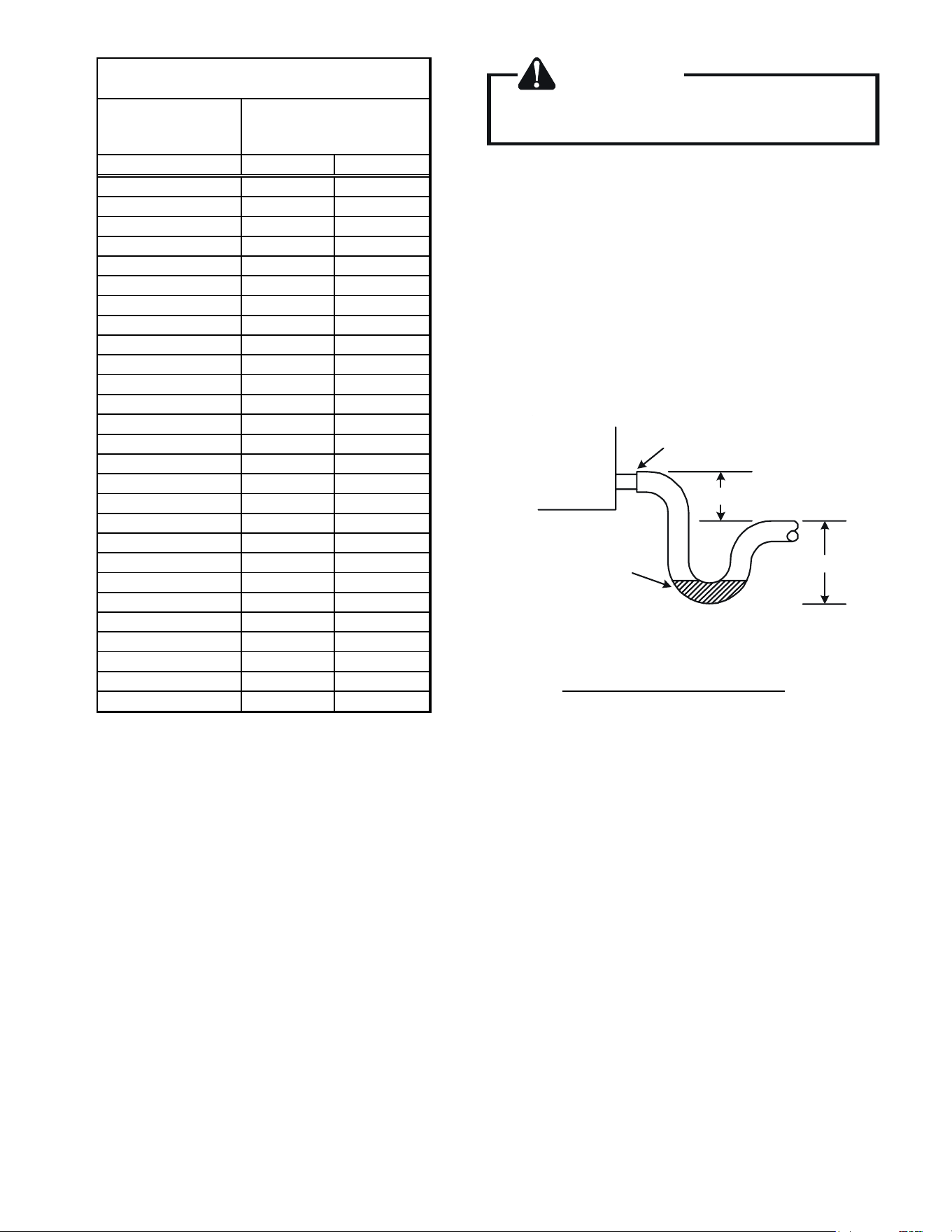
SUBCOOL FORMULA=
SAT. LIQUID LINE TEMP - LIQUID LINE TEMP
SUPERHEAT FORMULA=
SUCT. LINE TEMP - SAT. SUCT. TEMP
SUCTION PRESSURE
PSIG R-22 R-410A
50 26 1
52 28 3
54 29 4
56 31 6
58 32 7
60 34 8
62 35 10
64 37 11
66 38 13
68 40 14
70 41 15
72 42 16
74 44 17
76 45 19
78 46 20
80 48 21
85 50 24
90 53 26
95 56 29
100 59 31
110 64 36
120 69 41
130 73 45
140 78 49
150 83 53
160 86 56
170 90 60
SATURATED SUCTION PRESSURE
TEMPERATURE CHART
SATURATED SUCTION
TEMPERATURE ºF
8
SUCTION PRESSURE
PSIG R-22 R-410A
50 26 1
52 28 3
54 29 4
56 31 6
58 32 7
60 34 8
62 35 10
64 37 11
66 38 13
68 40 14
70 41 15
72 42 16
74 44 17
76 45 19
78 46 20
80 48 21
85 50 24
90 53 26
95 56 29
100 59 31
110 64 36
120 69 41
130 73 45
140 78 49
150 83 53
160 86 56
170 90 60
SATURATED SUCTION PRESSURE
TEMPERATURE CHART
SATURATED SUCTION
TEMPERATURE ºF
8 CondensateDrainLines
The coil drain pan has a primary and a secondary drain with 3/4”
NPT female connecons. The connectors required are 3/4” NPT
male, either PVC or metal pipe, and should be hand ghtened to
a torque of no more than 37 in-lbs. to prevent damage to the drain
pan connecon. An inseron depth of approximately 3/8” to 1/2”
(3-5 turns) should be expected at this torque.
1. Ensure drain pan hole is not obstructed.
2. To prevent potenal sweang and dripping on to nished
space, it may be necessary to insulate the condensate drain
line located inside the building. Use Armaex
®
or similar
material.
A secondary condensate drain connecon has been provided for
areas where the building codes require it. Pitch all drain lines a
minimum of 1/4” per foot to provide free drainage. Provide required
support to the drain line to prevent bowing. If the secondary drain
line is required, run the line separately from the primary drain and
end it where condensate discharge can be easily seen.
NOTE: Water coming from secondary line means the coil primary
drain is plugged and needs immediate aenon.
CAUTION
If secondary drain is not installed, the secondary
access must be plugged.
Insulate drain lines located inside the building or above a nished
living space to prevent sweang. Install a condensate trap to ensure
proper drainage.
NOTE: When units are installed above ceilings, or in other
locations where damage from condensate overow may occur,
it is MANDATORY to install a eld fabricated auxiliary drain
pan under the coil cabinet enclosure.
The installaon must include a “P” style trap that is located as close
as is praccal to the evaporator coil. See Figure 12 for details of a
typical condensate line “P” trap.
NOTE: Units operang in high stac pressure applicaons may re-
quire a deeper eld constructed “P” style trap than is shown in Fig-
ure 12 to allow proper drainage and prevent condensate overow.
Air Handler
3" MIN.
POSITIVE LIQUID
SEAL REQUIRED
AT TRAP
Drain
Connection
2" MIN.
Figure 11
NOTE: Trapped lines are required by many local codes. In the ab-
sence of any prevailing local codes, please refer to the requirements
listed in the Uniform Mechanical Building Code.
A drain trap in a draw-through applicaon prevents air from be-
ing drawn back through the drain line during fan operaon thus
prevenng condensate from draining, and if connected to a sewer
line to prevent sewer gases from being drawn into the airstream
during blower operaon.
Use of a condensate removal pump is permied when necessary.
This condensate pump should have provisions for shung o
the control voltage should a blocked drain occur. A trap must be
installed between the unit and the condensate pump.
IMPORTANT NOTE: The evaporator coil is fabricated with oils that
may dissolve styrofoam and certain types of plascs. Therefore,
a removal pump or oat switch must not contain any of these
materials.
Tip: Priming the “P” trap may avoid improper draining at the inial
installaon and at the beginning of the cooling season.
9
9 Ductwork
This air handler is designed for a complete supply and return
ductwork system.
To ensure correct system performance, the ductwork is to be sized
to accommodate 350-450 CFM per ton of cooling with the stac
pressure not to exceed 0.5” in w.c. Refer to ACCA Manual D, Manual
S and Manual RS for informaon on duct sizing and applicaon.
Flame retardant ductwork is to be used and sealed to the unit in a
manner that will prevent leakage.
NOTE: A downow applicaon with electric heat must have an
L-shaped sheet metal supply duct without any outlets or registers
located directly below the heater.
9.1 ReturnDuctwork
DO NOT LOCATE THE RETURN DUCTWORK IN AN AREA
THAT CAN INTRODUCE TOXIC, OR OBJECTIONABLE FUMES/
ODORS INTO THE DUCTWORK. The return ductwork is to be
connected to the air handler boom (upow conguraon).
10 Return Air Filters
Each installaon must include a return air lter. This ltering may
be performed at the air handler using the factory lter rails or
externally such as a return air lter grille. When using the factory
lter rails, a nominal 16x20x1”, 20x20x1” or 24x20x1” (actual
dimension must be less than 23-½”x20”) lter can be installed on
a B, C and D cabinet respecvely (the cabinet size is the seventh
leer of the model number).
11 Achieving1.4%and2.0%AirowLowLeakageRate
Ensure all the gaskets remain intact on all surfaces as shipped with
the unit. These surfaces are areas between the upper e plate and
coil access panel, blower access and coil access panels, and between
the coil access and lter access panels. Ensure upon installaon,
that the plasc breaker cover is sing ush on the blower access
panel and all access panels are ush with each other and the
cabinet. With these requirements sased, the unit achieves less
than 1.4% airow leakage @ 0.5 inch wc stac pressure and less
than 2% airow leakage @1inch wc stac pressure when tested in
accordance with ASHRAE Standard 193.
12 Electric Heat
Do not operate this product without all the ductwork
attached.
Refer to the installaon manual provided with the electric heat kit
for the correct installaon procedure. All electric heat must be
eld installed. If installing this opon, the ONLY heat kits that are
permied to be used are the HKS series. Refer to the air handler
unit’s Serial and Rang plate or the HKS specicaon sheets to
determine the heat kits compable with a given air handler. No
other accessory heat kit besides the HKS series may be installed
in these air handlers.
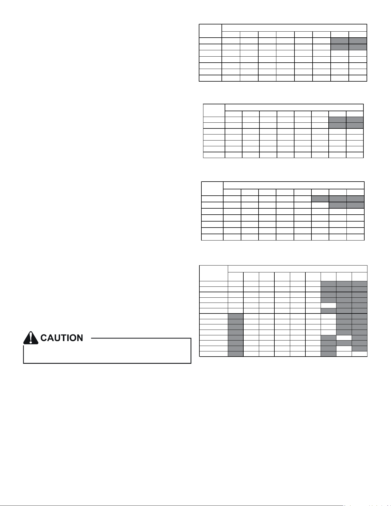
The heang mode temperature rise is dependent upon the system
airow, the supply voltage, and the heat kit size (kW) selected. Use
data provided in Tables 3, 4 and 5 to determine the temperature
rise (°F).
3 5 6 8 1 0 1 5 19/2 0 2 5
8 0 0 1 2 1 9 2 3 3 1 3 7 5 6
1 0 0 0 9 1 5 1 9 2 5 3 0 4 4
1 2 0 0 8 1 2 1 5 2 1 2 5 3 7 4 9 6 2
1 4 0 0 7 1 1 1 3 1 8 2 1 3 2 4 2 5 3
1 6 0 0 6 9 1 2 1 5 1 9 2 8 3 7 4 6
1 8 0 0 5 8 1 0 1 4 1 6 2 5 3 3 4 1
2 0 0 0 5 7 9 1 2 1 5 2 2 3 0 3 7
C FM
H EA T K IT N O M IN A L k W
230/1/60 SUPPLY VOLTAGE - TEMP. RISE °F
Table 3
3568 1 0 1 5 1 9 /2 0 2 5
8 0 0 1 1 1 8 2 2 3 0 3 5 5 4
1 0 0 0 9 1 4 1 8 2 4 2 8 4 2
1 2 0 0 7 1 2 1 5 2 0 2 4 3 5 4 7 5 9
1 4 0 0 6 1 0 1 3 1 7 2 0 3 0 4 0 5 1
1 6 0 0 6 9 1 1 1 5 1 8 2 7 3 5 4 4
1 8 0 0 5 8 1 0 1 3 1 6 2 4 3 1 3 9
2 0 0 0 479 1 2 1 4 2 1 2 8 3 5
C FM
H EAT K IT NO M IN A L k W
220/1/60 SUPPLY VOLTAGE - TEMP. RISE °F
Table 4
3568 1 0 1 5 1 9 /2 0 2 5
8 0 0 10 17 2 1 2 8 3 3
1 000 8 13 1 7 2 2 2 7 4 0
1 200 7 11 1 4 1 9 2 2 3 3 4 5 5 6
1 400 6 10 1 2 1 6 1 9 2 9 3 8 4 8
1 600 5 8 1 0 1 4 1 7 2 5 3 3 4 2
1 800 579 12 1 5 2 2 3 0 3 7
2 000 478 11 1 3 2 0 2 7 3 3
CFM
HEAT KIT NO M INAL k W
208/1/60 SUPPLY VOLTAGE - TEMP. RISE °F
Table 5
3568 10 15 19 20 25
AVPTC25B14 550 650 700 800 850 875
AVPTC29B14 550 650 700 800 875 875
AVPTC35B14 550 650 700 800 875 1050
AVPTC37B14 550 650 700 800 875 1050
AVPTC31C14 600 700 770 880 970 1090 1280
AVPTC33C14 600 700 750 850 920 950
AVPTC37C14 700 770 880 970 1090 1280
AVPTC39C14 700 770 880 970 1090 1280
AVPTC49C14 800 800 950 1090 1290 1345
AVPTC59C14 800 800 950 1090 1290 1345
AVPTC37D14 870 970 1060 1120 1220 1250
AVPTC49D14 950 1060 1150 1220 1520
AVPTC59D14 990 1110 1200 1240 1520 1520
AVPTC61D14 1030 1150 1250 1320 1650 1690 1750
HEATER
(kW)
Model
MINIMUM CFM REQUIREMENTS FOR HEATER KITS
Table 6
NOTE: For installaons not indicated above the following formula
is to be used:
TR = (kW x 3412) x (Voltage Correcon) / (1.08 x CFM)
Where: TR = Temperature Rise
kW = Heater Kit Actual kW
3412 = Btu per kW
VC* = .96 (230 Supply Volts)
= .92 (220 Supply Volts)
= .87 (208 Supply Volts)
1.08 = Constant
CFM = Measured Airow
VC*(VoltageCorrecon)
10
NOTE: The Temperature Rise Tables can also be used to esmate
the air handler airow delivery. When using these tables for this
purpose set the room thermostat to maximum heat and allow the
system to reach steady state condions. Insert two thermometers,
one in the return air and one in the supply air. The temperature
rise is the supply air temperature minus the return air temperature.
Using the temperature rise calculated, CFM can be esmated from
the TR formula above. See Spec Sheets and/or Service Manual for
more informaon.
13 Electrical and Control Wiring
IMPORTANT: All roung of electrical wiring must be made through
provided electrical knockouts. Do not cut, puncture or alter the
cabinet for electrical wiring.
13.1 BuildingElectricalServiceInspecon
This unit is designed for single-phase electrical supply only.
DO NOT OPERATE ON A THREE-PHASE POWER SUPPLY. Mea-
sure the power supply to the unit. The supply voltage must
be measured and be in agreement with the unit nameplate
power requirements and within the range shown.
Nominal Input Minimum Voltage Maximum Voltage
208-240 197 253
ELECTRICAL VOLTAGE
Table 7
13.2 WireSizing
Wire size is important to the operaon of your equipment.
Use the following check list when selecng the appropriate
wire size for your unit.
FIRE HAZARD!
To avoid the risk of property damage, personal injury
or fire, use only copper conductors.
HIGH VOLTAGE!
Failure to do so may cause property damage,
personal injury or death.
Disconnect ALL power before servicing.
Multiple power sources may be present.
HIGH VOLTAGE!
To avoid property damage, personal injury or death
due to electrical shock, this unit MUST have an
electrical ground. The
electrical ground circuit may consist of an
appropriately sized electrical wire connecting the
ground lug in the unit control box to the building
electrical service panel.
Other methods of grounding are permitted if performed
in accordance with the National Electric Code
(NEC)/American National Standards Institute
(ANSI)/National Fire Protection Association (NFPA) 70
and local/state codes. In Canada, electrical grounding
is to be in accordance with the Canadian Electric Code
(CSA) C22.1.
uninterrupted, unbroken
• WireusedmustcarrytheMinimumCircuitAmpacity(MCA)
listedontheunit’sSeriesandRangPlate.
• Refer to the NEC (USA) or CSA (Canada) for wire sizing. The
unit MCA for the air handler and the oponal electric heat
kit can be found on the unit Series and Rang Plate.
• Wiremustbesizedtoallownomorethana2%voltage
dropfromthebuildingbreaker/fusepaneltotheunit.
• Wires with dierent insulaon temperature rang have
varying ampacies - be sure to check the temperature rang
used.
Refer to the latest edion of the Naonal Electric Code or in
Canada the Canadian Electric Code when determining the
correct wire size.
13.3 MaximumOvercurrentProtecon(MOP)
Every installaon must include an NEC (USA) or CEC (Canada)
approved overcurrent protecon device. Also, check with
local or state codes for any special regional requirements.
Protecon can be in the form of fusing or HACR style circuit
breakers. The Series and Rang Plate provides the maximum
overcurrent device permissible.
NOTE: Fuses or circuit breakers are to be sized larger than
the equipment MCA but not to exceed the MOP.
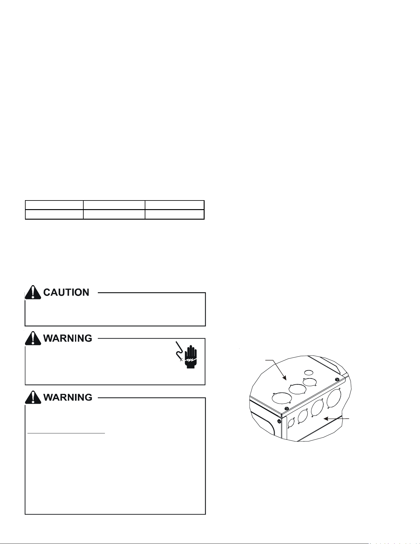
13.4 ElectricalConnecons–SupplyVoltage
IMPORTANT NOTE: USE COPPER CONDUCTORS ONLY.
Knockouts are provided on the air handler top panel and
sides of the cabinet to allow for the entry of the supply volt-
age conductors, as shown in Figure 13. If the knockouts on
the cabinet sides are used for electrical conduit, an adapter
ring must be used in order to meet UL1995 safety require-
ments. An NEC or CEC approved strain relief is to be used
at this entry point. Some codes/municipalies require the
supply wire to be enclosed in conduit. Consult your local
codes.
Side of
Cabinet
Top of
Cabinet
KNOCK-OUT FOR ELECTRICAL CONNECTIONS
Figure 12
11
13.4.1AirHandlerOnly(Non-HeatKitModels)
The building supply connects to the stripped black and red
wires contained in the air handler electrical compartment
cavity. A ground screw is also contained in this area. Aach
the Supply wires to the air handler conductors as shown in
the unit wiring diagram using appropriately sized solderless
connectors or other NEC or CEC approved means.
13.4.2AirHandler-Non-CircuitBreakerHeatKits
A terminal block is provided with the HKS kit to aach the
power supply and air handler connecons. Follow the HKS
Installaon Manual and wiring diagram for complete wiring
details.
13.4.3AirHandlerWithCircuitBreakerHeatKit
The air handler has a plasc cover on the upper access panel
that will require either one or both secons to be removed
to allow the heat kit circuit breaker(s) to be installed. The
circuit breakers have lugs for power supply connecon. See
the HKS Installaon Instrucons for further details.
14 AVPTCMotorOrientaon
If the unit is in the upow posion, there is no need to rotate the
motor. If the unit is in the downow posion, loosen motor mount
and rotate motor as shown in the AVPTCMotorOrientaon gure
below. Be sure motor is oriented with the female connecons on
the casing down. If the motor is not oriented with the connecons
down, water could collect in the motor and may cause premature
failure.
FEMALE CONNECTIONS
SIDE VIEW
W
A
RNING
SOFTW
A
RE VER.
TOP
FRONT VIEW
AVPTC Motor Orientaon
Figure 13
15CoolCloudHVACPhoneApplicaon
NOTE: This equipment has been tested and found to comply with
the limits for a Class B digital device, pursuant to part 15 of the FCC
Rules. These limits are designed to provide reasonable protecon
against harmful interference in a residenal installaon. This equip-
ment generates, uses and can radiate radio frequency energy and,
if not installed and used in accordance with the instrucons, may
cause harmful interference to radio communicaons. However,
there is no guarantee that interference will not occur in a parcular
installaon. If this equipment does cause harmful interference to
radio or television recepon, which can be determined by turning
the equipment o and on, the user is encouraged to try to correct
the interference by one or more of the following measures:
—Reorient or relocate the receiving antenna.
—Increase the separaon between the equipment and receiver.
—Connect the equipment into an outlet on a circuit dierent
from that to which the receiver is connected.
—Consult the dealer or an experienced radio/ TV technician
for help.
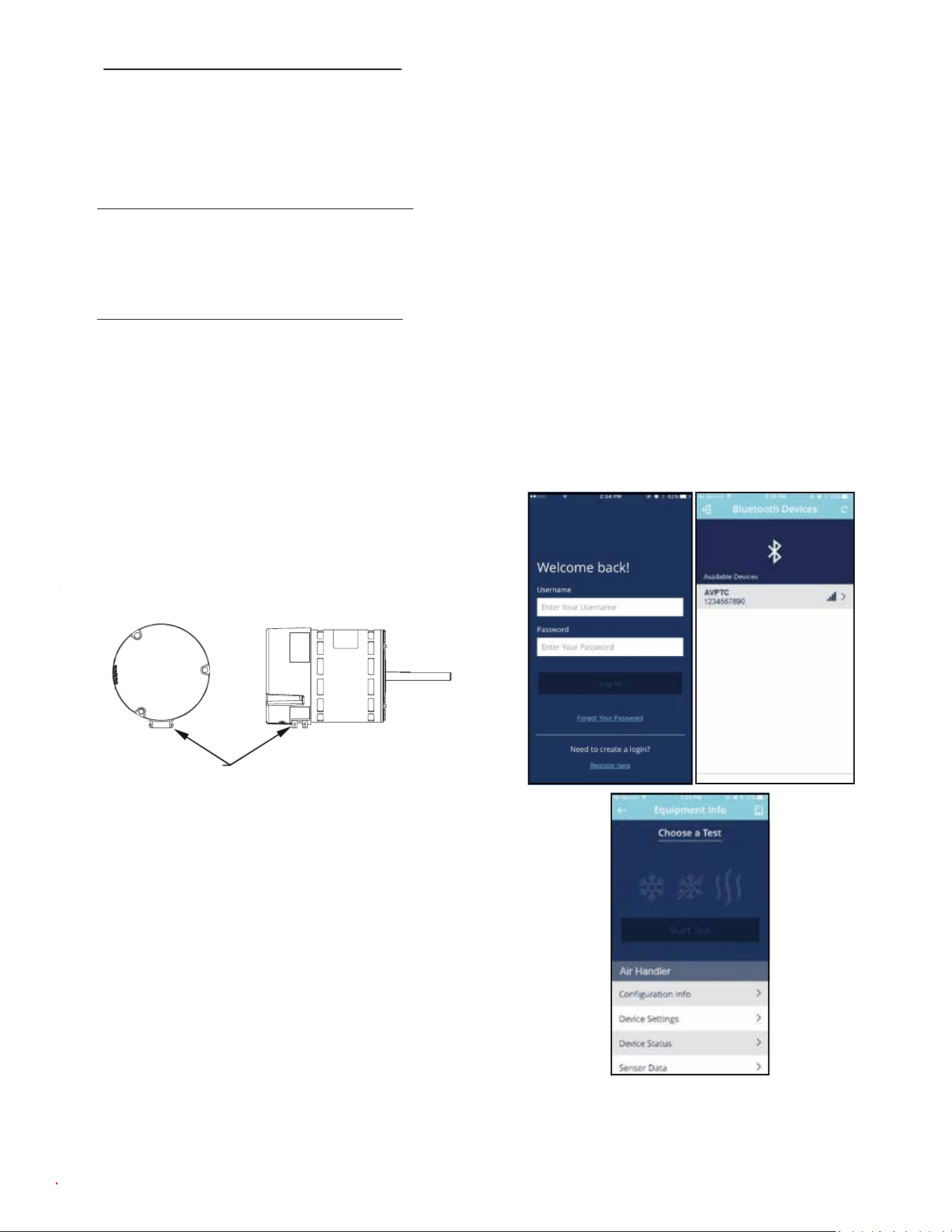
Actual screens may look dierent based on the mobile device
being used.
Figure 14
12
This air handler is Bluetooth ready and funcons with the Cool
Cloud HVAC phone applicaon designed to improve the contrac-
tor’s setup / diagnosc experience. Users can see specic model
informaon, review acve diagnosc error codes, observe system
menu tesng of all operaonal modes (heat / cool / fan) directly
from the phone. The phone applicaon is also capable of directly
updang the air handler soware anyme updates are available.
The applicaon will automacally nofy the user.
NOTE: The soware update may take up to 20 minutes to complete.
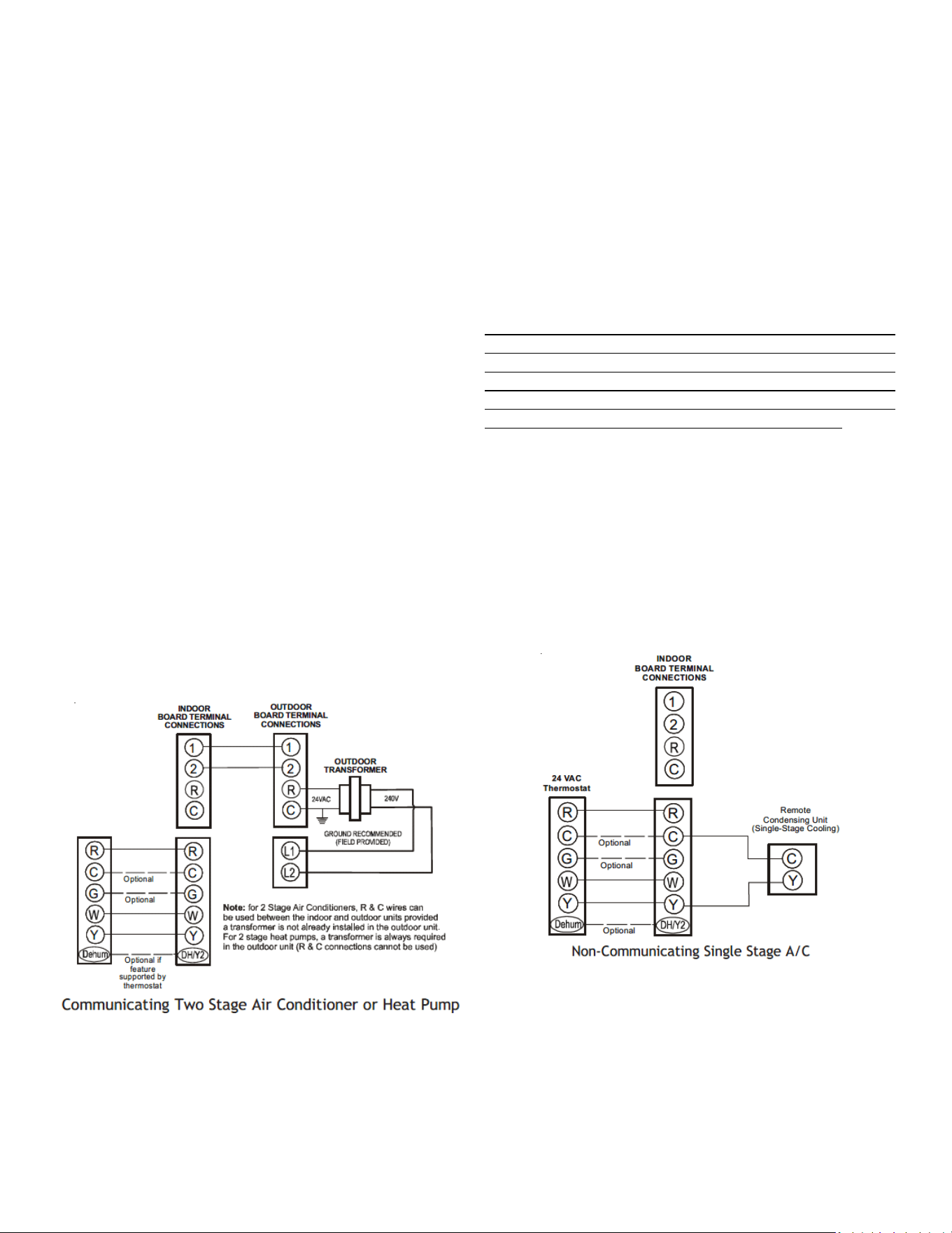
16 QuickStartGuideforCommunicangOutdoorUnits
EXTREMELY IMPORTANT: For all cooling calls the system only re-
quires a single Y input from the thermostat. For all heang calls
(including applicaons with backup electric heater kits) the system
only requires a single W input from the thermostat. Internal algo-
rithms will control all available cooling and heang stages based
on these inputs. Any single-stage 24VAC thermostat can be used.
For proper operaon, the thermostat must be setup to control a
single stage AC outdoor unit and to control single stage electric
heat operaon. The control board does not accommodate an O
wire thermostat input (reversing valve signal). If a heat pump is
installed, the thermostat should be setup as stated above. Seng
the thermostat for the heat pump control or mulstage control
may result in incorrect performance.
1. Connect all necessary thermostat wires to the thermostat
connector on the air handler control as instructed by the
applicable wiring diagrams shown in this secon.
2. Connect the 1 & 2 wires between the indoor and outdoor
unit for communicang operaon.
Note: Verify two stage outdoor units include a 24VAC
transformer (for outdoor control board power). Two stage
outdoor units may not behave properly without this 24 VAC
transformer.
Figure 15
3. Download the Cool Cloud HVAC phone applicaon for
charging and to congure /test system.
NOTE: When new versions of Bluetooth Communicaon Soware
and Air Handler Control Soware are available, the phone appli-
caon noes the user. Soware updates are classied as either
oponal or mandatory and installed by using the phone applicaon.
Ensure all mandatory soware updates and install if necessary.
16.1 Charging
1. Two-stage outdoor units using the Cool Cloud HVAC appli-
caon:
a. Using the cooling icon aer entering the outdoor
unit menus, energize the outdoor unit at 49%
capacity or lower.
b. Charge the outdoor unit as required using the
charging informaon provided with the outdoor
equipment.
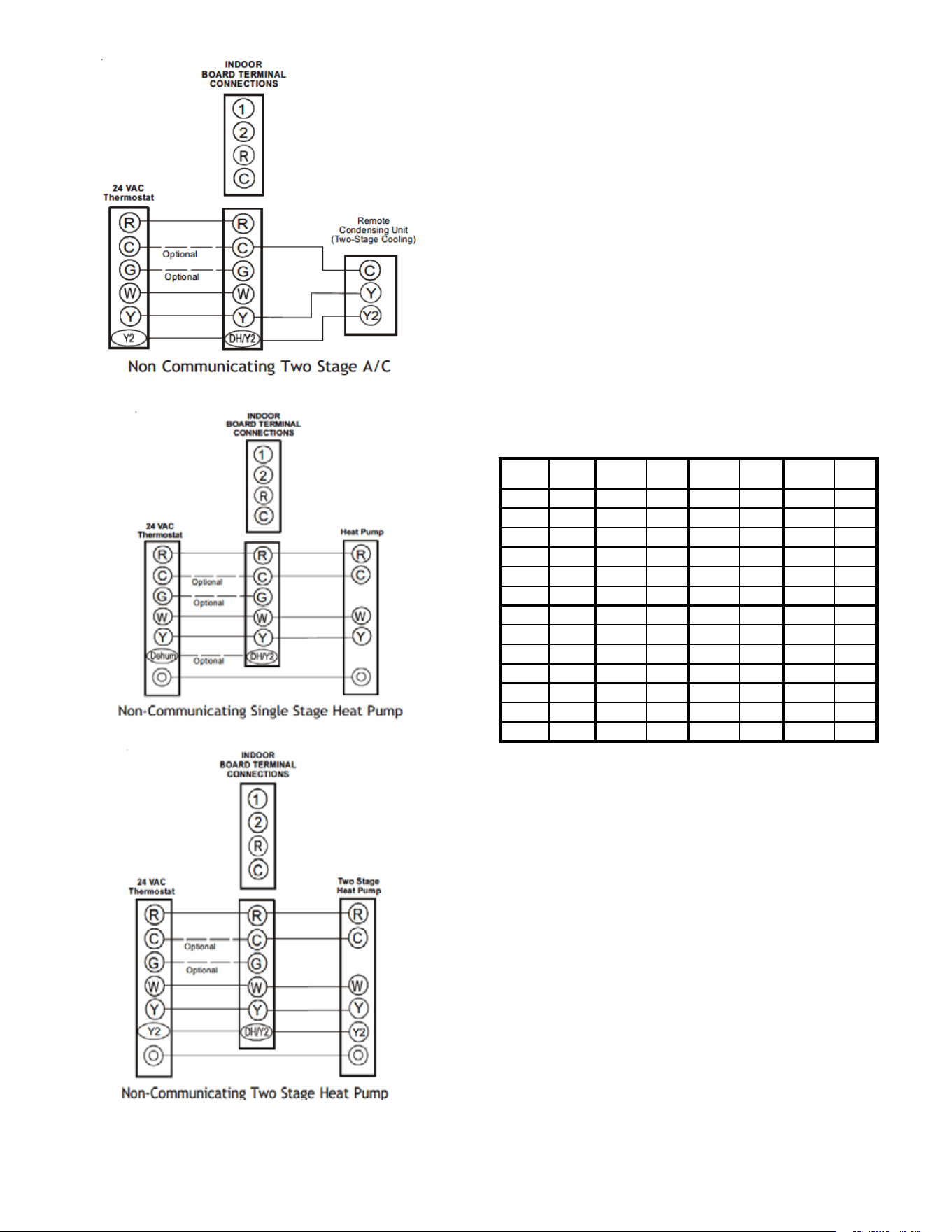
17 QuickStartGuideforNon-CommunicangOutdoor
Units
Whenseng up a ComfortBridgeair handler foruse with a
Non-Communicangoutdoorunityou mustset airow in the
“ton” menu on the PCB or in the CoolCLoud HVAC APP. Failure
to do so will result in the air handler PCB displaying “IdL” and the
blowerwillnotoperatewithacallforcooling.TheBoarddoes
notneedtobereplaced,youMUSTsettheairowrst.
EXTREMELY IMPORTANT: For two stage electric heat kit control
the system only needs a single W input. Internal algorithms will
control staging automacally based on the single W input. For
non-communicang outdoor unit wiring, see instrucons below:
1. Use the wiring diagrams on the next page to connect low
voltage thermostat wires.
NOTE: When installing the air handler with a non-com-
municang heat pump, wire directly to the “O” terminal
on the non-communicang heat pump. See the following
gures.
Figure 16
13
FIgure 17
Figure 18
Figure 19
2. Download the Cool Cloud HVAC phone applicaon.
Note: When new versions of Bluetooth Communicaon
Soware and Air Handler Control Soware are available,
the phone applicaon noes the user. Soware updates
are classied as either oponal or mandatory and installed
by using the phone applicaon. Ensure all mandatory
soware updates have been installed. Review notes for
oponal soware updates and install if necessary.
3. Go to the Non-Comm Outdoor Seng Menu () using
the on board push buons or the Cool Cloud HVAC phone
applicaon. Selec t “” for single stage Air Condioners,
“” for single stage Heat Pumps, “” for two stage Air
Condioners and “” for 2 stage Heat Pumps.
4. Go to the Tonnage Units Menu () and select the ton-
nage value that corresponds to the desired airow for the
outdoor unit. See the following table.
NOTE: For the two stage non-communicang outdoor
units, system will stage airow automacally for low stage
operaon.
Tonnage
Selecon
Airow
Tonnage
Selecon
Airow
Tonnage
Selecon
Airow
Tonnage
Selecon
Airow
1 400 2.3 920 3.6 1440 4.9 1960
1.1 440 2.4 960 3.7 1480 5 2000
1.2 480 2.5 1000 3.8 1520 5.1 2040
1.3 520 2.6 1040 3.9 1560 5.2 2080
1.4 560 2.7 1080 4 1600 5.3 2120
1.5 600 2.8 1120 4.1 1640 5.4 2160
1.6 640 2.9 1160 4.2 1680 5.5 2200
1.7 680 3 1200 4.3 1720 5.6 2240
1.8 720 3.1 1240 4.4 1760 5.7 2280
1.9 760 3.2 1280 4.5 1800 5.8 2320
2 800 3.3 1320 4.6 1840 5.9 2360
2.1 840 3.4 1360 4.7 1880 6 2400
2.2 880 3.5 1440 4.8 1920
NOTE: The system will not provide airows above the max Airow
Value.
14
ModelM AX CFM
AVPTC25B14
AVPTC29B14
AVPTC35B14
AVPTC37B14
1200
AVPTC33C14 1300
AVPTC31C14
AVPTC37C14
AVPTC39C14
1600
AVPTC37D14
AVPTC49C14
1800
AVPTC49D14
AVPTC59C14
1900
AVPTC59D14
AVPTC61D14
2100
5. Use the Cool Cloud HVAC phone applicaon to congure/
test air handler operaons.
NOTE: The phone applicaon cannot test a non- communicang
outdoor unit. The thermostat will be required for outdoor unit
tesng.
17.1 ElectricHeaterKitTesng
1. Select the electric heat icon aer entering the air handler
menus while using the Cool Cloud phone applicaon.
2. Select any value less than 50% for low stage operaon and
any value greater than 50% for high stage operaon.
3. Conrm thermostat heang and cooling calls funcon
properly for high stage operaon.
18 Dehumidicaon
Dehumidicaon allows the air handler’s circulator blower to
operate at a reduced speed during a combined thermostat call
for cooling and a dehumidicaon call from the thermostat or
humidistat. This lower blower speed increases dehumidicaon
of the condioned air as it passes through the indoor coil. The
control board is equipped with a 24 volt dehumidicaon input
(DH) located on the thermostat wiring connector. The terminal
can be congured to enable dehumidicaon when the input is
energized or de-energized. When using an external dehumidistat,
connect it between the R and DH terminals. If the humidistat
closes on humidity rise or the thermostat energizes this terminal
when dehumidifcaon is required, set the control board Dehum
Logic Menu () to “” using the push buons or Cool Cloud
HVAC phone applicaon. If the humidistat opens on humidity or
the thermostat de-energizes this terminal when dehumidicaon
is required, set the Dehum Logic Menu to “” using the push
buons or Cool Cloud HVAC phone applicaon.
19 Auxiliary Alarm Switch
The control is equipped with a 24VAC Aux Alarm to be
used for a condensate switch install (designated by CON-DENSATE
IN/OUT on the control). By default, the connected
AUX switch is normally closed and opens when the
water level in the evaporator coil base pan reaches an
undesirable level. The control responds by displaying a “” error
code and turning o the outdoor condensing
unit. If the AUX switch is detected to be in the closed
posion for 30 seconds, normal operaon resumes and
the error message is no longer displayed.
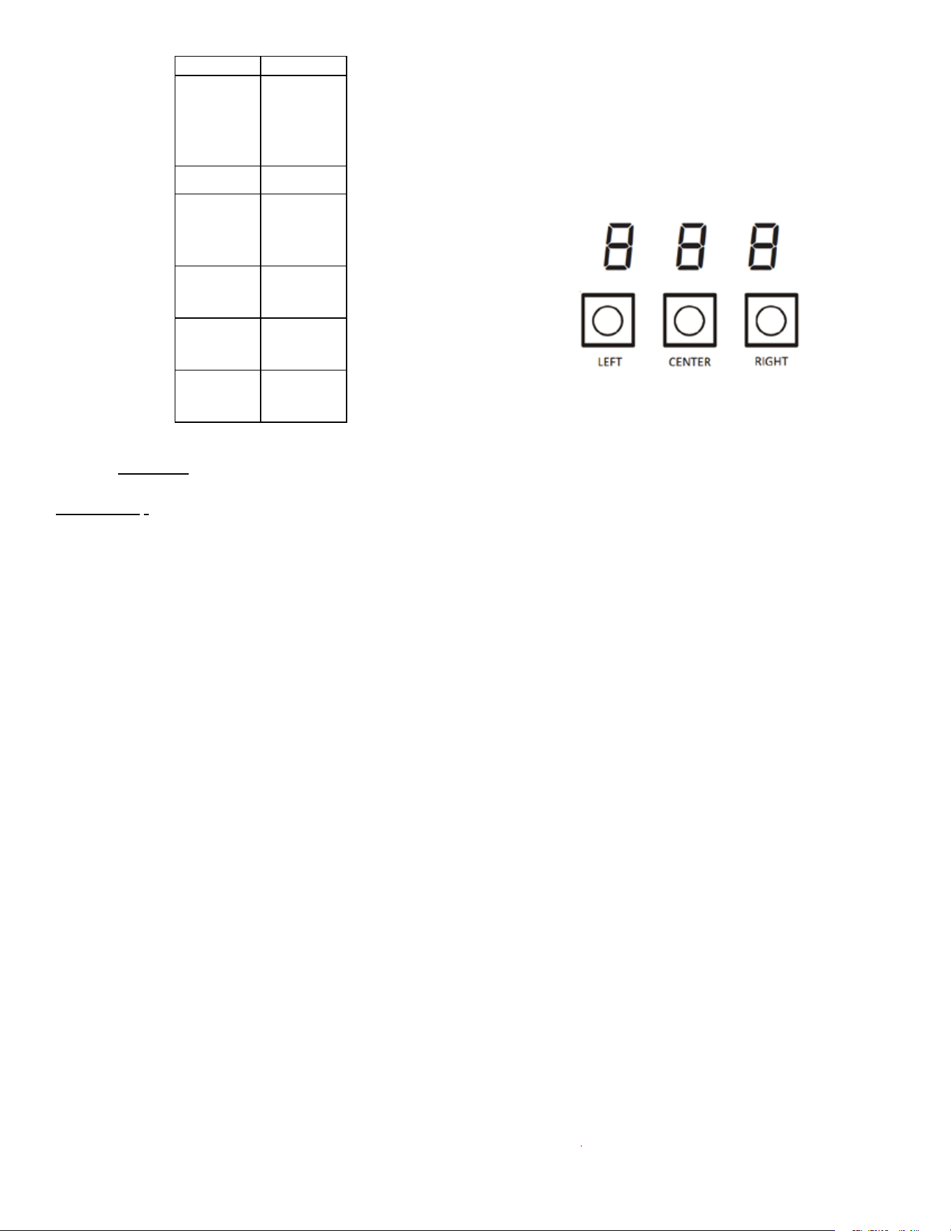
20 Start-Up Procedure
Figure 20
The air handler includes three on-board push buons allowing
users to navigate indoor and outdoor system menus.
The Right and Le buons allow the user to scroll through
the main menus and to then scroll through available opons
within specic menus. The Center buon is used to
enter into a main menu and to then permanently select
opons within those menus.
NOTE: Aer scrolling to the desired opon within a menu,
that opon may be ashing on the 7-segment displays.
This indicates the opon has not been ocially selected.
Pressing the Center buon two mes will select that
opon. The rst press will stop the ashing. The second
will make the selecon ocial and return you to the main menu.
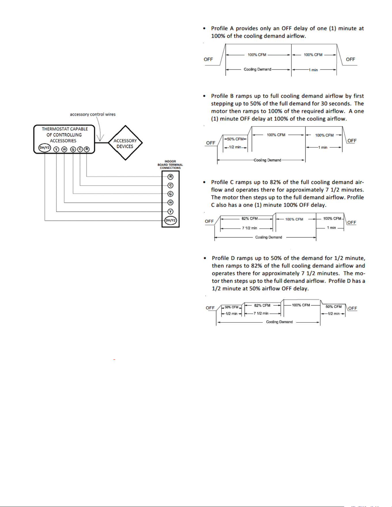
21 AccessoryControl(Humidiers,Dehumidiers,Ven-
lators)
If an external humidier, dehumidier or venlator is installed,
it may require airow from the HVAC system to
funcon properly.
15
1. Make sure the installed 24VAC thermostat is capable of
controlling the accessory or accessories.
2. Connect the appropriate accessory control wires to the
accessory devices from the thermostat (see thermostat
manual for connecon and setup instrucons).
3. If the thermostat is capable of providing a connuous fan
call (G signal) during accessory operaon:
Make sure to connect the thermostat G terminal to the G
terminal on the indoor unit. Setup thermostat to ensure G
signal is energized during accessory operaon.
FIgure 21
4. Select the appropriate fan only airow for the accessory
using the indoor unit push buon menus or the Cool Cloud
HVAC phone applicaon.
5. Using the thermostat, independently test each accessory
in addion to the independently tesng connuous fan
mode.
22 RampingProles
The variable-speed circulator oers four dierent ramping
proles. These proles may be used to enhance cooling perfor-
mance and increase comfort level. Select the desired ramping
prole using the Cool Cloud phone applicaon or the push buon
menus.
Figure 22
16
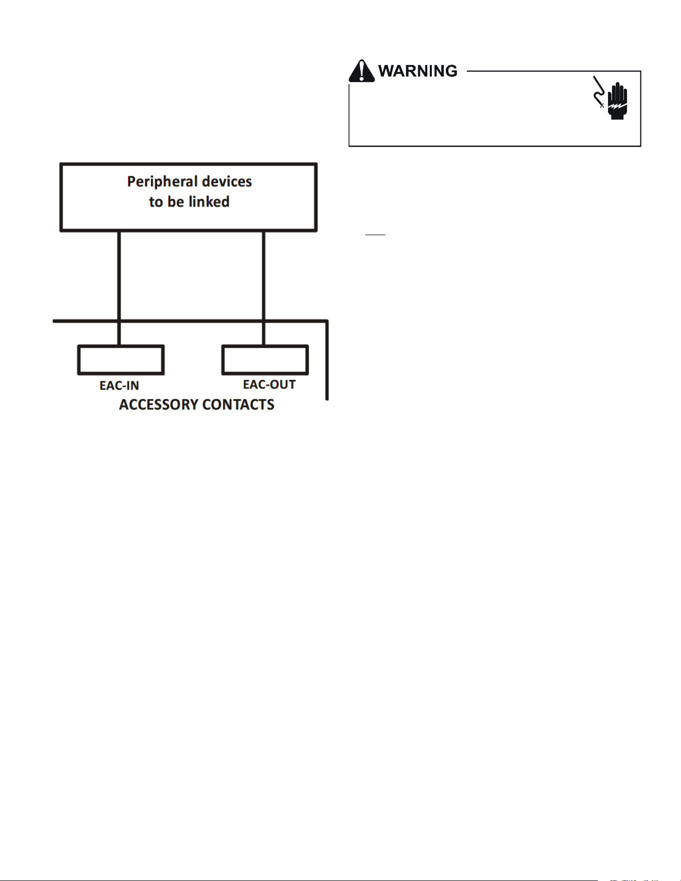
23 Electric Air Cleaner Warning
The control is equipped with an Accessory Relay and a pair of ¼
inch accessory terminals which is normally open, labeled EAC-IN
and EAC-OUT (see accessory contacts graphic). The Accessory Re-
lay is congured to close anyme the blower is running. A closed
relay means the two terminals will have connuity between them
(the control does not energize these contacts). It is recommended
to ulize 24VAC with these terminals and limit the current to 1A.
FIgure 23
24 Start-Up Procedure
• Prior to start-up, ensure that all electrical connecons are
properly sized and ghtened.
• All panels must be in place and secured. For Air Tight appli-
caon, neoprene gasket must be posioned at prescribed
locaons to achieve low airow as stated in secon 13.
• Tubing must be leak free.
• Unit should be elevated, trapped and pitched to allow for
drainage.
• Low voltage wiring is connected.
• Auxiliary drain is installed when necessary and pitched to
allow for drainage.
• Drain pan and drain tubing has been leak checked.
• Return and supply ducts are sealed.
• Unit is elevated when installed in a garage or where am-
mable vapors may be present.
• Unit is protected from vehicular or other physical damage.
• Return air is not obtained from any areas where there may
be objeconable odors, ammable vapors or products of
combuson such as carbon monoxide (CO), which may cause
serious personal injury or death.
25 Regular Maintenance
HIGH VOLTAGE!
Failure to do so may cause property damage,
personal injury or death.
Disconnect ALL power before servicing.
Multiple power sources may be present.
The only item to be maintained on a regular basis by the user is
the circulang air lter(s). Filter should be cleaned or replaced
regularly. A cered service technician must perform all other
services.
NOTE: THESE INSTRUCTIONS ARE SPECIFICALLY FOR AVPTC MODELS.
DO NOT USE THESE DIAGRAMS FOR ANY OTHER MODELS. SEE
SEPARATE INSTALLATION AND OPERATING INSTRUCTIONS FOR ATUF,
ARUF, ARPT, ADPF, AND ASPF MODELS.
NOTICE: THIS PRODUCT CONTAINS ELECTRONIC COMPO-
NENTS WHICH REQUIRE A DEFINITE GROUND. PROVISIONS
ARE MADE FOR CONNECTION OF THE GROUND. A DEDICATED
GROUND FROM THE MAIN POWER SUPPLY OR AN EARTH
GROUND MUST BE PROVIDED.
17
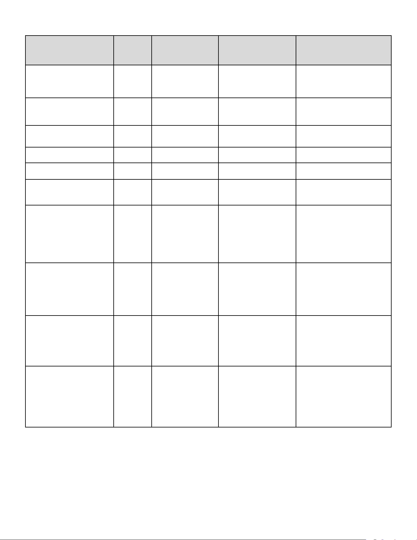
26 AirHandlerTroubleshoongMatrix
Symptoms of Abnormal Operation
Diagnostic /
Status LED
Codes
Fault Description Possible Causes Corrective Actions
No outdoor unit operations
Communication error with
outdoor unit
Improper low voltage wiring between
the indoor and outdoor unit
Outdoor control board lost power
duirng operation
Locate and correct improper low voltage wiring
issue
Identify reason outdoor control board lost power
during operation
No Air Handler operation
Open fuse Short in low voltage wiring
Locate and correct short in low voltage wiring
Replace fuse with 3-amp automotive type
No Air Handler operation
Auxiliary switch (condensate
switch) open or open fuse
High water level in the evaporation coil
or short in low voltage wiring
Check evaporator drain pan, trap, piping
Replace fuse with 3-am automotive type
No Air Handler operation
Data not yet on network No network data Populate shared data set using memory card
No Air Handler operation
Invalid memory card data
Air Handler blower does not contain
an appropriate shared data set
Populate correct shared data using memory
card
Operation different than expected or no ope
r
Invalid memory card data
Shared data set on memory card has
been rejected by integrated control
module
Verify shared data set is correct for the specifc
model. Re-populate data using correct memory
card if required
No Air Handler operation
Circulator blower motor not
running with demand present
Loose or disconnected wiring
connection at circulator motor power
leads
Open circuit in inductor or loose
wiring connection at inductor (3/4 Hp
and 1 Hp models only)
Failed circulator blower motor
Tighten or correct wiring connection
Verify continuous circuit through inductor.
Replace if open or short circuit
Check circulator blower motor
No Air Handler operation
Integrated control module has
lost communications with
circulator blower motor
Loose wiring connection at circulator
motor control leads
Failed circulator blower motor
Failed integrated control module
Tighten or correct wiring connection
Check circulator blower motor, replace if
necessary
Check integrated control module, replace if
necessary
No Air Handler operation
Circulator blower motor horse
power in shared data set does
not match circulator blower
motor horse power
Incorrect circulator blower motor in Air
Handler
Incorrect shared data set in integrated
control module
Verify circulator blower if motor horse power is
the same specifed for the specifc Air Handler
model, replace if necessary
Verify shared data set is correct for the specifc
model, re-populate data using correct memory
card if required
Air Handler operates at reduced
performance
Airfow delivered is less than expected
Circulator blower motor is
operating in a power,
temperature, or speed limiting
condition
Blocked flters
Restrictive or undersized ductwork
High ambient temperatures
Check filters for blockage, clean flters or
remove obstruction
Check ductwork for blockage, remove
obstruction and verify all registers are fully open
Verify ductwork is appropriately sized for
system and resize/replace ass needed

18
26 AirHandlerTroubleshoongMatrix(connued)
Symptoms of Abnormal
Operation
Diagnostic /
Status LED
Codes
Fault Description
Possible Causes
Corrective Actions
No Air Handler operation
Circulator blower motor
senses a loss of rotor
control
Circulator blower motor
senses high current
Abnormal motor loading,
sudden change in speed or
torque, sudden blockage of air
handler air inlet or outlet
Check filters, filter grills/registers,
duct system and air handler
inlet/outlet for blockages
No Air Handler operation
Circulator blower motor
fails to start 10
consecutive times
Obstruction in circulator
blower housing
Seized Circulator blower
motor bearings
Failed circulator blower motor
Check circulator blower for
obstructions
Remove and repair/replace
wheel/motor if necessary
Check circulator blower motor shaft
rotation and motor, replace motor if
necessary
No Air Handler operation
Circulator blower motor
shuts down for over or
under voltage condition
Circulator blower motor
shuts down due to over
temperature condition on
power module
High or low AC line voltage to
air handler
High ambient temperatures
Check power to air handler
Verify line voltage is within the range
specified on the rating plate
No Air Handler operation
Circulator blower motor
does not have enough
information to operate
properly
Motor fails to start 40
consecutive times
Error with integrated control
module shared data
Verify control is populated with the
correct shared data
Air Handler operates at reduced
performance or operates on low
stage when high stage is expected
Airflow is lower than
demanded
Blocked filters or restrictive
ductwork
Undersized ductwork
Check filters for blockage, clean
filters or remove obstruction
Check ductwork for blockage,
remove obstruction and verify all
registers are fully open
Verify ductwork is appropriately sized
for system, resize/replace ductwork if
necessary
19
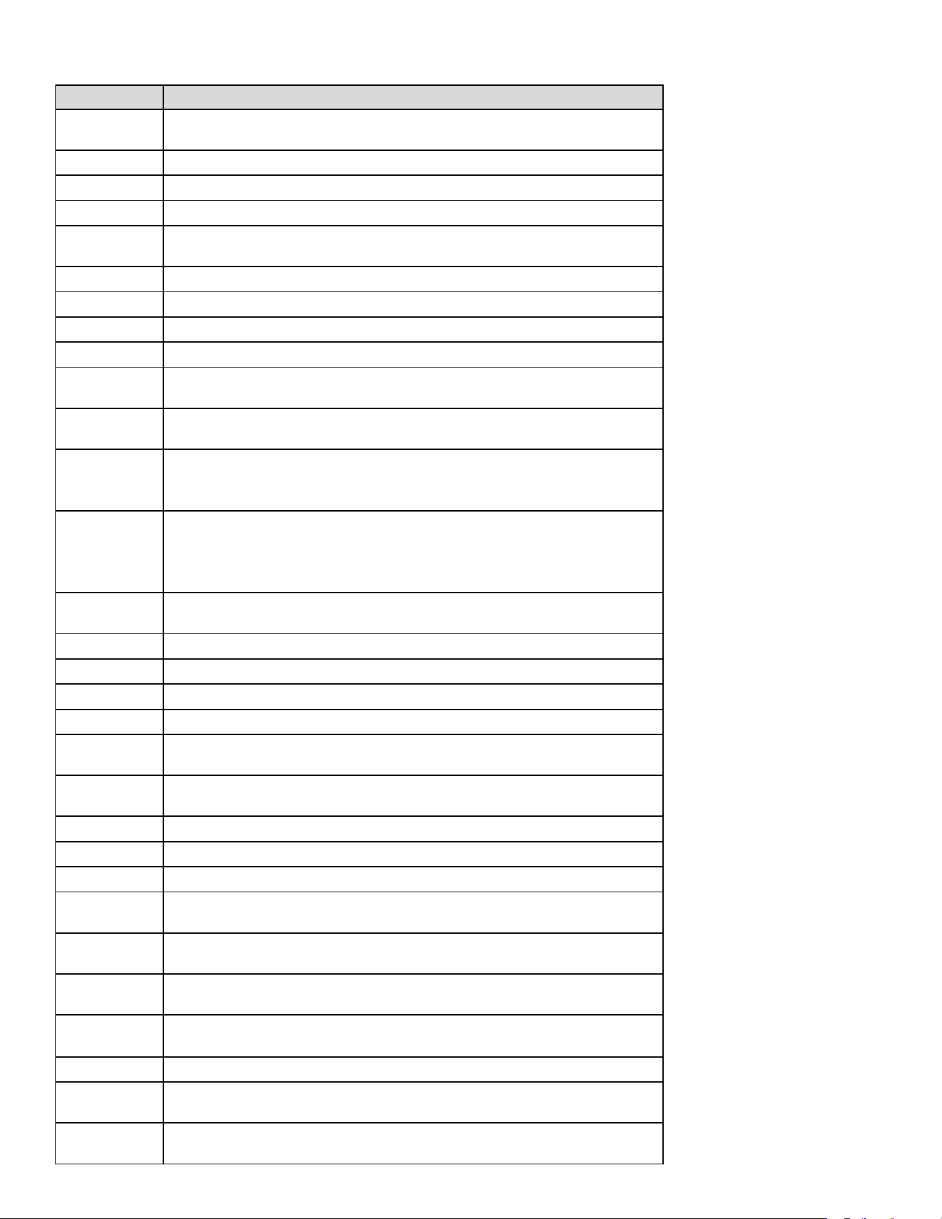
27 Air Handler Display
LED Display
Menu Description
View 6 most recent fault codes and Clear Fault Codes if desired
(furnace)
Restart communications between the indoor and outdoor unit.
Control Firmware Revision Number
Control Shared Data Revision Number
Constant Fan Speed as percent of maximum airflow. Default = 30%
Electric Heater Kit Wattage (kW)
Electric Heat Off Delay (seconds)
Electric Heat On Delay (seconds)
Electric Heat Airflow Trim (percentage)
Percentage of high stage electric heating airflow to run duirng low
stage electric heat operation
1 = system will try to satisfy the thermostat quickly.
5 (default) = system will try to satsify the thermostat more slowly.
Select "" to enable dehumidification when the thermostat DH
terminal is energized. Select "" to enable dehumidification when
the thermostat DH terminal is de-energized. (default = )
Select number of stages for the non-communicating outdoor unit.
( for single-stage Air Conditioners, for single stage Heat
Pumps, for two stage Air Conditioners or for two stage heat
pumps)
Indoor Airflow for non-communicating outdoor units. (values based
on 400CFM per ton) (default = 3.0 Ton)
Cooling Airflow Trim (default 0%)
Cooling Airflow Profile setting (default = profile D shown as 4)
Cooling Airflow On Delay Time (default = 5 seconds)
Cooling Airflow Off Delay Time. (default = 60 seconds)
Percentage of high stage cooling airflow to run during low stage
operation. (default = 70%)
Electric heat operation during defrost. 1 = low stage 2 (default) =
high stage
Heat Pump Indoor Airflow Trim (default = 0%)
Heat Pump Heating Airflow Off Delay Time (default = 60 seconds)
Heat Pump Heating Airflow On Delay Time (default = 5 seconds)
Percentage of high stage heat pump heating airflow to run during
low stage operation. (defaullt = 70%)
When heat pump heating and electric heat are running at the same
time, this percentage is used for additional airflow trim
Enables or disables dehumidification feature in the outdoor unit.
(default = Enabled)
Balance point temperature. The Compressor will not operate below
temperature. (Default = 0°F)
Backup Heat Balance Points
Compressor run time between defrost cycles. (default = 30 minutes)
(2 stage units)
Compressor off delay at the beginning and end of a defrost cycle.
(default = 30 seconds)
20
27 AirHandlerDisplay(connued)
LED Display
Menu Description
View 6 most recent fault codes and Clear Fault Codes if desired
(outdoor communicating units)
Menu is enabled if the menu is set to 6. Select the target time
the system will attempt to satisfy the thermostat.
Menu is enabled if the menu is set to 6. Select the percentage
past the target time when the system will enable electric heat
operation during heat mode.
Menu is enabled if the is set to 6. (Electric heat will run during
the next heat call if the heat pump fails to satisfy the custom target
time for this number of consecutive cycles) (default = 20 cycles)
Menu is enabled if the menu is set to 6. (if the addition of low
stage electric heat is able to consecutively satisfy the thermostat
under the set target time for this number of cycles, the system will
transition to the heat pump for primary heating)
Menu is enabled if the menu is set to 6. (this percentage will
help determine when switching back to heat pump only operation is
appropriate. Default = 20%. If target time = 20 minutes, the addtion
of low stage electric heat must staisfy the thermostat by less than 16
minutes. (target time - 20% default = 16 minutes).
21
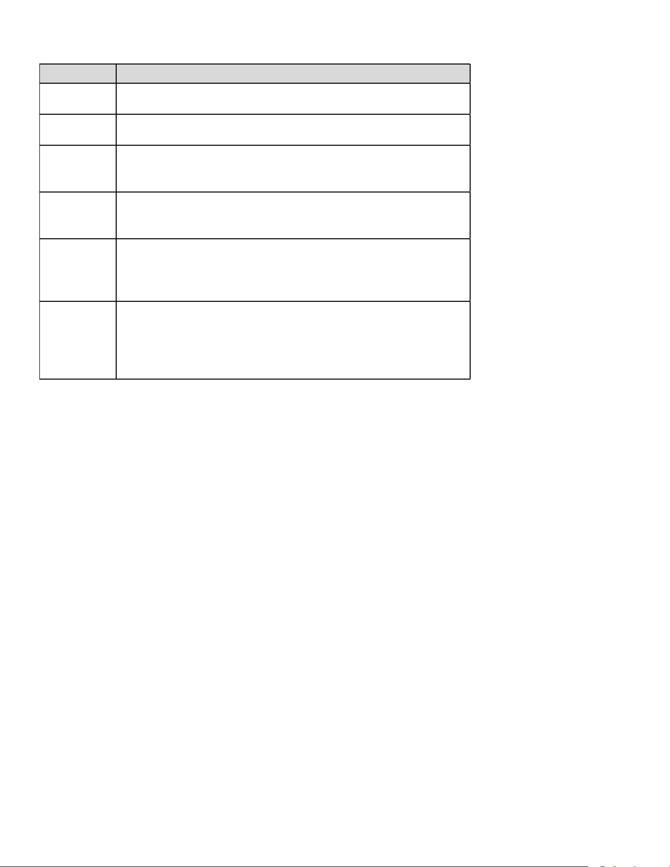
27 AirHandlerDisplay(connued)
LED Display Descrip�on of System Status
Idle
Constant Fan
Compressor Cooling, Single-Stage (non-comm units)
Compressor Cooling, Low Stage (non-comm units)
Compressor Cooling, High Stage (non-comm units)
Compressor Cooling, Low Stage (comm units)
Compressor Cooling, High Stage (comm units)
Compressor Heat, Single-Stage (non-comm. units)
Compressor Heat, Low Stage (non-comm units)
Compressor Heat, High Stage (non-comm units)
Compressor Heat, Low Stage (Comm Units)
Compressor Heat, High Stage (Comm Units)
Electric Heat, Single Stage
Electric Heat, Low Stage
Electric Heat, High Stage
*
Defrost, Single Stage Electric Heat (non-comm units)
Defrost, Low Stage Electric Heat
Defrost, High Stage Electric Heat
Dehumidification
* If a system is a heat pump connected legacy, then a DFT will show on the
board in 2 instances.
1. If the heat pump calls for a defrost, Y and a W will be energized resulting
in a DFT code on the air-handler display.
2. If the heat pump calls for auxiliary heat, Y and a W will be energized
resulting in a DFT code on the air-handler display.
22
28AirFlowLabel
0140A00615-C
Airflow Settings Instructions
1) For non-communicating installations, select the type of unit installed
in the OdS menu (1AC = single-stage air conditioner,
1HP = single-stage heat pump, 2AC = 2 stage air conditioner,
2HP = 2 stage heat pump) Default = OFF (no outdoor unit).
2) Use the Tonnage Menu (ton ) to select Cooling/Heat Pump Airflow
(non-communicating installation). Tonnage selection options and
corresponding airflow CFM can be found to the right.
[Airflow = Tonnage Selection x 400] Default selection is 6.0 tons.
3) [Optional] Use the Cooling Trim Menu (CtF) to adjust the cooling
airflow from -10% to +10% (2% increments). This applies for 2
stage communicating outdoor units and single or 2 stage
non-communicating outdoor units.
4) [Optional] Use the Heating Trim Menu (HtF) to adjust the heat pump
airflow from -10% to +10% (2% increments). This applies for 2
stage communicating outdoor units and single or 2 stage
non-communicating outdoor units.
5) [Optional]Use the Constant Fan Menu (FSD) to select the
percentage of maximum airflow for continuous fan
6) [Optional]Use the Cooling Airflow Profile Menu (CAP) to select
between 5 cooling airflow profiles. Profile options 1-4 are listed above
(option 5 is adjustable). See installation manual for further details
Profiles
Pre-Run Short-Run OFF Delay
1 -------- -------- 60 sec/100%
2 -------- 30 sec/50% 60 sec/100%
3 -------- 7.5 min/82% 60 sec/100%
4 30 sec/50% 7.5 min/82% 60 sec/100%
Selecting Heater Kit: Use the Electric Heating Wattage Menu (EHt) to select heater kit size. See "Menu Navigation and Selection Instructions"
above. Default selection is 0 (No Heat Kit). Select installed heater kit for heater kit operation.
NR - Not Rated
++ For match up with a 3 ton outdoor unit: Airflow for 5kW up to 15kW heater kits shall be set to 1220 CFM by selecting 10 in the
Electric Heating Wattage (EHt) menu.
+++ For match up with a 3.5 ton outdoor unit: Heater kit application shall not exceed 20 kW. Airflow for 5kW up to 20kW heater kits
shall be set to 1500 CFM by selecting 8 in the Electric Heating Wattage (EHt) menu.
Electric Heat Airflow Table
Menu Navigation and Selection Instructions
Using Phone Application over Bluetooth Network:
1) Connect to the air handler (instructions provided by phone during
connection process).
2) Select desired settings menu
3) Select item that requires adjustment and make necessary selection
4) Submit Changes
Using On-Board Push Buttons:
1) Use the Right and Left Buttons to scroll between menus
2) Use the Center Button to select desired menu when menu code is
shown on 7-segment displays
3) Use the Left and Right Buttons to scroll through options within the
desired menu (the display will flash while scrolling through options for
selection)
4) Use the Center Button to select the displayed option (when selected
the display will stop flashing)
5) Use the Center Button to finalize selection and return to the main
menu
*If airflow is set above the model's maximum value, the output will be the
maximum value
Maximum Airflow Output
Tonnage
Selection
Airflow
1.0 400
1.1 440
1.2 480
1.3 520
1.4 560
1.5 600
1.6 640
1.7 680
1.8 720
1.9 760
2.0 800
2.1 840
2.2 880
2.3 920
2.4 960
2.5 1000
2.6 1040
2.7 1080
2.8 1120
2.9 1160
3.0 1200
3.1 1240
3.2 1280
3.3 1320
3.4 1360
3.5 1400
Tonnage Menu (t o n)
Tonnage
Selection
Airflow
3.5 1400
3.6 1440
3.7 1480
3.8 1520
3.9 1560
4.0 1600
4.1 1640
4.2 1680
4.3 1720
4.4 1760
4.5 1800
4.6 1840
4.7 1880
4.8 1920
4.9 1960
5.0 2000
5.1 2040
5.2 2080
5.3 2120
5.4 2160
5.5 2200
5.6 2240
5.7 2280
5.8 2320
5.9 2360
6.0 2400
AVPTC2 5B14
AVPTC2 9B14
AVPTC3 5B14
AVPTC3 7B14
AVPTC33C14
AVPTC31C14
AVPTC37C14
AVPTC39C14
AVPTC37D14
AVPTC49C14
AVPTC49D14
AVPTC59C14
AVPTC5 9D14
AVPTC6 1D14
1200 13001600 1800 1900 2100
Htr Kw
3
5
6
8
10
15
19
20
21
25 NR
NR
NR
NR NR
NR
NR
NR
NR
NR
NR
NR
NR
NR
NR
NR
NR
NR
NR
NR
NR
NR
NR
NR
NR
NR
NR
NR
NR
NR
NR
NR
NR
NR
NR
NR
1750
1690
1320
1250
1150
1030
NR
NR
NR
NR
870
970
1060
1120
1220
1345
NR
800
800
950
1090
1290
1280
NR
700
770
880
970
1090
NR
600
600
700
770
880
970
1090
550
650
700
800
875
1050
550
650
700
875
800
875
550
650
700
800
850
875
1280
700
750
850
920
950
1250
950
1060
1150
1220
1520
990
1110
1200
1270
1520
1520
AVPTC61D14
+++
AVPTC49D14
++
AVPTC49C14
AVPTC59C14
AVPTC37C14
AVPTC39C14
AVPTC35B14
AVPTC37B14
AVPTC59D14
AVPTC37D14AVPTC33C14AVPTC31C14AVPTC29B14AVPTC25B14
1650
23
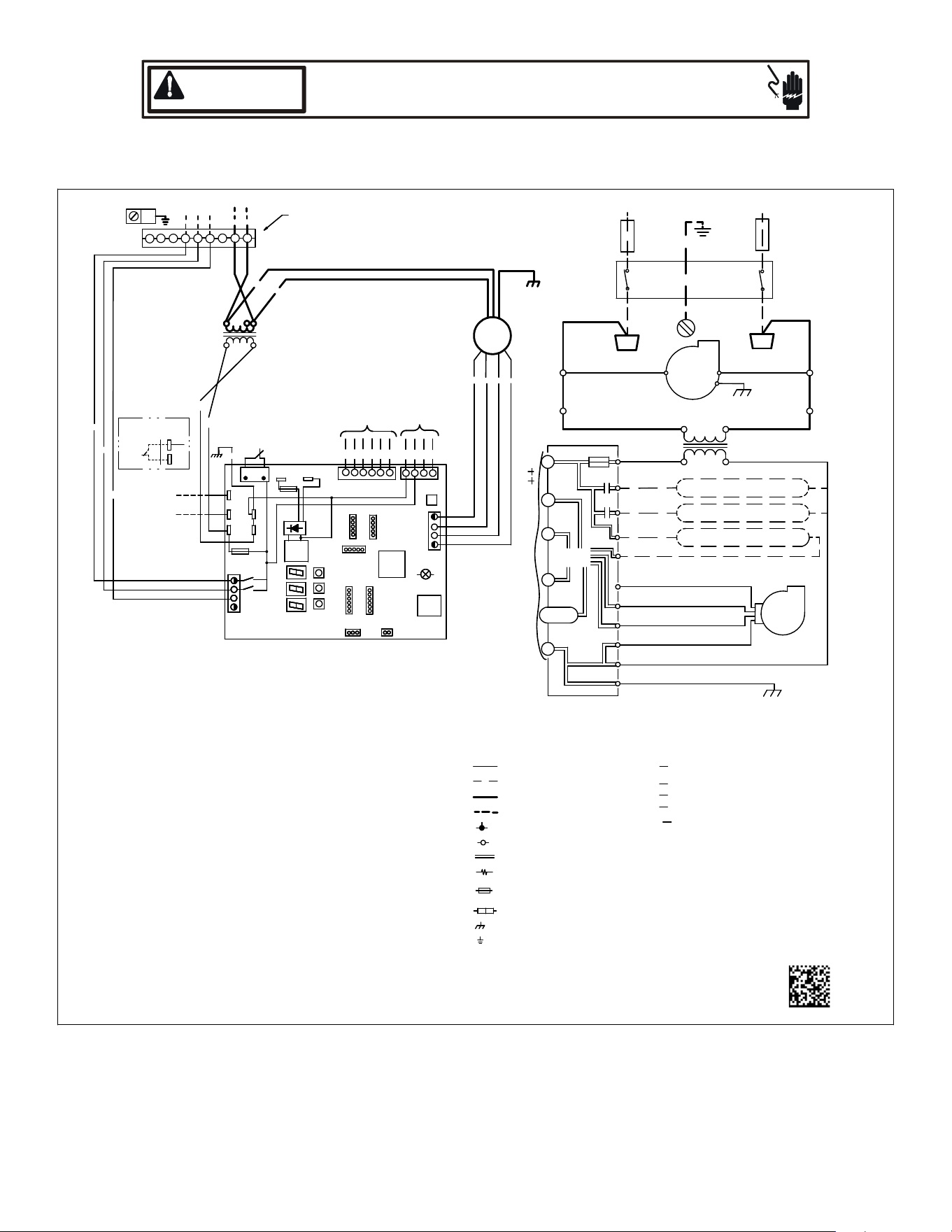
29 Wiring Diagrams
HIGH VOLTAGE!
DISCONNECT ALL POWER BEFORE SERVICING.
MULTIPLE POWER SOURCES MAY BE PRESENT. FAILURE TO DO SO
MAY CAUSE PROPERTY DAMAGE, PERSONAL INJURY OR DEATH.
WARNING
0140A00716-A
HEATER KIT
OUTPUT
BK
RD
BL
BR
WH
RD BK
GROUND LUG
(SEE NOTE 4)
24VAC
AUX
IN
AUX
OUT
INSTALLING
AUX ALARM
(ALARM)
(SEE NOTE 7)
~
~
~
~
~
~
208
VAC
230
VAC
TR1
(SEE NOTE 1)
FAN
MOTOR
BK
RD
GY
BL
ECM MOTOR
PL1
PL2
9
7
8
4 5
6
3
2 1
INTEGRATED CONTROL:
POWER/HEATER
CONNECTOR
PL1, PL2
COMPONENT CODES:
TL
F1U, F2U
TR
THERMAL LIMIT
TRANSFORMER
FUSE LINK
NOTES:
1. PLACE RED WIRE ON 208 V TERMINAL OF TRANSFORMER (TR1)
FOR 208 VAC OPERATION.
2. MANUFACTURER'S SPECIFIED REPLACEMENT PARTS MUST BE USED
WHEN SERVICING.
3. IF ANY OF THE ORIGINAL WIRES AS SUPPLIED WITH THIS UNIT MUST
BE REPLACED, IT MUST BE REPLACED WITH WIRING MATERIAL
HAVING A TEMPERATURE RATING OF AT LEAST 105°C. USE COPPER
CONDUCTORS ONLY.
4. UNIT MUST BE PERMANENTLY GROUNDED AND CONFORM TO N.E.C
AND LOCAL CODES.
6. DISCARD CONNECTOR PL1 WHEN INSTALLING OPTIONAL HEAT KIT.
7. REMOVE JUMPER TAB AND PUT AUX ALARM SWITCH WHEN
INSTALLING AUX ALARM SWITCH.
9. USE N.E.C CLASS 2 WIRE.
10. SEE MANUAL FOR PUSH BUTTON OPERATION.
11. SEE MANUAL FOR 7-SEGMENT DISPLAY DIAGNOSTIC CODES AND
MENU CODES
12. SEE MANUAL FOR LED FUNCTIONALITY.
13. R AND C TERMINALS (USED FOR 24VAC OUTDOOR CONTROL
VOLTAGE) ARE OPTIONAL FOR 2 STAGE
COMMUNICATING AIR
CONDITIONERS. R AND C TERMINALS ARE NOT TO BE USED FOR 2
STAGE COMMUNICATING HEAT PUMP APPLICATIONS.
FOR COMMUNICATING HEAT PUMPS OR IF ONLY TWO THERMOSTAT
WIRES ARE AVAILABLE, A SEPARATE TRANSFORMER MUST BE
INSTALLED IN THE OUTDOOR UNIT FOR CONTROL BOARD POWER.
1 AND 2 WIRES ARE REQUIRED FOR ALL APPLICATIONS. SEE
INSTALLATION MANUAL FOR FULL SYSTEM WIRING EXAMPLES.
COLOR CODES:
BL - BLUE
RD - RED
YL - YELLOW
OR - ORANGE
BK - BLACK
GY - GREY
BR - BROWN
GR - GREEN
PU - PURPLE
WH - WHITE
LOW VOLTAGE
LOW VOLTAGE FIELD
HIGH VOLTAGE
HIGH VOLTAGE FIELD
JUNCTION
TERMINAL
INTERNAL TO
RESISTOR
OVERCURRENT
PROT. DEVICE
PLUG CONNECTION
EQUIPMENT GND
FIELD GROUND
J13
J14
PS
F1U
TH1
TR1
TB1
TB2
AUX
OUT
AUX
IN
TB7
COM
PS
TR2
TB4
AUX ALARM
(ALARM)
GR
AUX ALARM
RELAY IN
RELAY OUT
(SEE NOTE 6)
GY
BK
OUTDOOR UNIT
208/230 VAC
TO
HEATER KIT
TRANSFORMER
CONNECTOR
PL3, PL4
PS
TH2
TB3
F2U
TB6
EAC-OUT
EAC-IN
TB5
RELAY IN
(EAC-OUT)
RELAY OUT
(EAC-IN)
JTAG
TEMPERATURE)
FLASH WRITER
TEMPERATURE)
J19
J5
LEGACY INPUT
Y
G
W
C
R
C
R 2 1
DH/Y2
J3
MONITOR
RAM
AC
DATA
CT COMM
J2
J1
GRND
AIR
COM
W
208/230 VAC
CONDENSATE AUX SWITCH
INDOOR
L1
HEAT 1 COIL/R1
TR2
INTEGRATED CONTROL MODULE
CIRCULATOR
GRND
BLWR
BLWR
W2 (2)
L2
40 VA
R
TO
TH2
CIRCULATOR
L1
INDOOR
24 VAC
AIR
CAS (1)
FUSE 3 A
GRND
Y
W1 (1)
CAS (2)
TRANSFORMER
DISCONNECT
HEAT 2 COIL/ R2
L2
J11
UART5
THERMOSTAT
L2
L1
PU
GY
WH
GR
BL
RD
BL
RD
(SEE NOTE 13)
SHARE
DATA
BL
RD
COM
24
Wiring is subject to change. Always refer to the wiring diagram on the unit for the most up-to-date wiring.
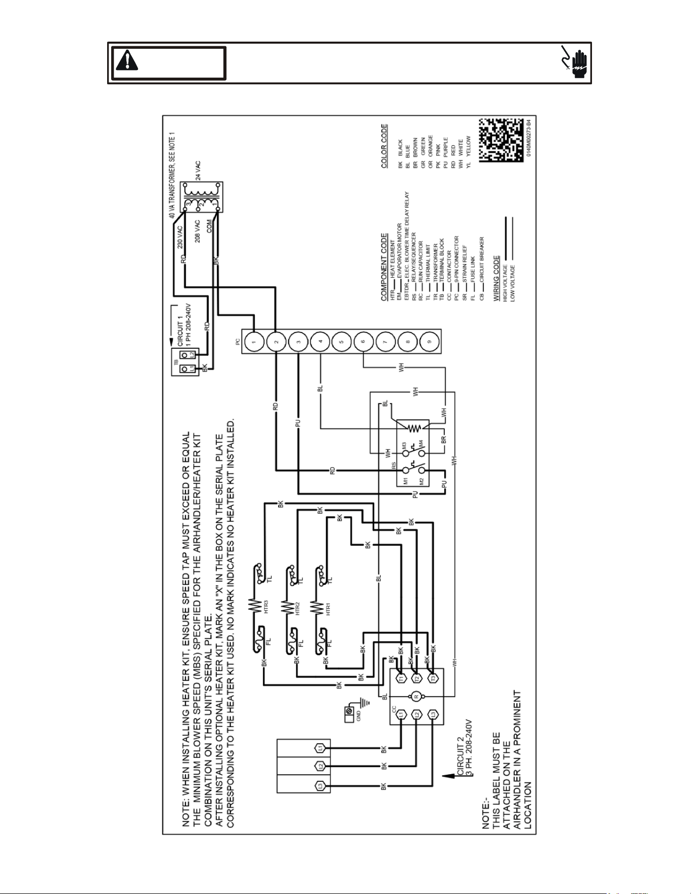
HIGH VOLTAGE!
DISCONNECT ALL POWER BEFORE SERVICING.
MULTIPLE POWER SOURCES MAY BE PRESENT. FAILURE TO DO SO
MAY CAUSE PROPERTY DAMAGE, PERSONAL INJURY OR DEATH.
WARNING
3-Phase Heat Kit
29 Wiring Diagrams
25
BEFORE YOU CALL YOUR SERVICER
• Check the thermostat to conrm that it is properly set.
• Wait 15 minutes. Some devices in the outdoor unit or
in programmable thermostats will prevent compressor
operaon for awhile, and then reset automacally. Also,
some power companies will install devices which shut o
air condioners for several minutes on hot days. If you wait
several minutes, the unit may begin operaon on its own.
• Check the electrical panel for tripped circuit breakers or
failed fuses. Reset the circuit breakers or replace fuses as necessary.
• Check the disconnect switch near the indoor furnace or blower to conrm that it is closed.
• Check for obstrucons on the outdoor unit . Conrm that it has not been covered on the sides or the top. Remove any obstrucon
that can be safely removed. If the unit is covered with dirt or debris, call a qualied servicer to clean it.
• Check for blockage of the indoor air inlets and outlets. Conrm that they are open and have not been blocked by objects (rugs,
curtains or furniture).
• Check the lter. If it is dirty, clean or replace it.
• Listen for any unusual noise(s), other than normal operang noise, that might be coming from the outdoor unit. If you hear
unusual noise(s) coming from the unit, call a qualied servicer.
AIR HANDLER
AIR HANDLER HOMEOWNER’S ROUTINE MAINTENANCE RECOMMENDATIONS
Westronglyrecommendabi-annualmaintenancecheckupbeperformedbeforetheheangandcoolingseasonsbeginbyaqualiedservicer.
REPLACE OR CLEAN FILTER
IMPORTANT NOTE: Never operate unit without a lter installed as dust and lint will build up on internal parts resulng in loss of e-
ciency, equipment damage and possible re.
An indoor air lter must be used with your comfort system. A properly maintained lter will keep the indoor coil of your comfort system
clean. A dirty coil could cause poor operaon and/or severe equipment damage.
Your air lter or lters could be located in your furnace, in a blower unit, or in “lter grilles” in your ceiling or walls. The installer of your
air condioner or heat pump can tell you where your lter(s) are, and how to clean or replace them.
Check your lter(s) at least once a month. When they are dirty, replace or clean as required. Disposable type lters should be replaced.
Reusable type lters may be cleaned.
You may want to ask your dealer about high eciency lters. High eciency lters are available in both electronic and non-electronic
types. These lters can do a beer job of catching small airborne parcles.
MOTORS
Indoor and outdoor fan motors are permanently lubricated and
do not require addional oiling.
ALUMINUM INDOOR COIL CLEANING
(QUALIFIEDSERVICERONLY)
This unit is equipped with an aluminum tube evaporator coil. The
safest way to clean the evaporator coil is to simply ush the coil
with water. This cleaning pracce remains as the recommended cleaning method for both copper tube and aluminum tube residenal
evaporator coils.
It has been determined that many coil cleaners and drain pan tablets contain corrosive chemicals that can be harmful to aluminum
tube and n evaporator coils. Even a one-me applicaon of these corrosive chemicals can cause premature aluminum evaporator
coil failure. Any cleaners that contain corrosive chemicals including, but not limited to, chlorine and hydroxides, should not be used.
An alternate cleaning method is to use one of the products listed in TP-109* to clean the coils. The cleaners listed are the only agents
deemed safe and approved for use to clean round tube aluminum coils. TP-109 is also available on the web site in Partner Link > Service
Toolkit.
NOTE: Ensure coils are rinsed well aer use of any chemical cleaners.

26
THIS PAGE WAS LEFT BLANK INTENTIONALLY

27
THIS PAGE WAS LEFT BLANK INTENTIONALLY
28
© 2018-2020 Goodman Manufacturing Company, L.P.
19001 Kermier Rd., Waller, TX 77484
www.goodmanmfg.com - or - www.amana-hac.com
is a registered trademark of Maytag Corporaon or its related companies and is used under license. All rights reserved.
CUSTOMER FEEDBACK
We are very interested in all product comments.
Please ll out the feedback form on one of the following links:
Goodman® Brand Products: (hp://www.goodmanmfg.com/about/contact-us).
Amana® Brand Products: (hp://www.amana-hac.com/about-us/contact-us).
You can also scan the QR code on the right for the product brand
you purchased to be directed to the feedback page.
PRODUCT REGISTRATION
Thank you for your recent purchase. Though not required to get the protecon of
the standard warranty, registering your product is a relavely short process, and
entles you to addional warranty protecon, except that failure by California and
Quebec residents to register their product does not diminish their warranty rights.
For Product Registraon, please register as follows:
Goodman® Brand products: (hps://www.goodmanmfg.com/product-registraon).
Amana® Brand products: (hp://www.amana-hac.com/product-registraon)
You can also scan the QR code on the right for the product brand
you purchased to be directed to the Product Registraon page.
GOODMAN® BRAND
AMANA® BRAND
AMANA® BRAND
GOODMAN® BRAND