AP15875-2 (05/11)
!
FOR YOUR SAFETY!
— Do not store or use gasoline or other
flammable vapours or liquids or other
combustible materials in the vicinity of this or
any other appliance. To do so may result in an
explosion or fire.
— WHAT TO DO IF YOU SMELL GAS
● Do not try to light any appliance.
● Do not touch any electrical switch; do not
use any phone in your building.
● Immediately call your gas supplier from
a neighbour’s phone. Follow the gas
supplier’s instructions.
● If you cannot reach your gas supplier, call
the fire department.
● Do not return to your home until authorized
by the gas supplier or fire department.
—Improper installation, adjustment, alteration,
service or maintenance can cause property
damage, personal injury, or death. Refer to
this manual. Installation and service must be
performed by a qualified installer, service
agency or the gas supplier.
WARNING: If the information in these instructions is not followed exactly,
a fire or explosion may result causing property damage, personal injury or death.
!
Thepurposeofthismanualistwofold:one,toprovidetheinstallerwiththebasicdirectionsand
recommendationsfortheproperinstallationandadjustmentofthewaterheater;andtwo,fortheowner–
operator,toexplainthefeatures,operation,safetyprecautions,maintenanceandtroubleshootingofthe
waterheater.Thismanualalsoincludesapartslist.
Itisimperativethatallpersonswhoareexpectedtoinstall,operateoradjustthiswaterheaterreadthe
instructionscarefullysotheymayunderstandhowtoperformtheseoperations.Ifyoudonotunderstand
theseinstructionsoranytermswithinit,seekprofessionaladvice.
Anyquestionsregardingtheoperation,maintenance,serviceorwarrantyofthiswaterheatershould
bedirectedtothesellerfromwhomitwaspurchased.Ifadditionalinformationisrequired,refertothe
sectionon“Ifyouneedservice.”
Do not destroy this manual. Please read carefully and keep in a safe place for future reference.
Recognize this symbol as an indication of Important Safety Information!
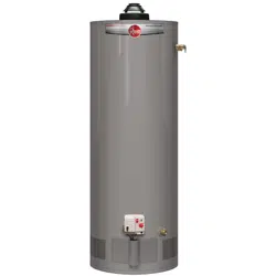
Residential38,40and50Gallon
Use&CareManual
WithInstallationInstructionsfortheInstaller
WaterHeaters
CERTIFIED
R
Warning: This water heater is not suitable
for use in manufactured (mobile) homes!
!
!
ResidentialGas-FVIR Certified
W I T H D A M P E R & E L E C T R O N I C C O N T R O L
Printed in USA
Customer Service
Parts List . . . . . . . . . . . . . . . 26
If You Need Service . . . . . . .28
FORYOURRECORDS
Writethemodelandserialnumbershere:
#
#
Youcanfindthemonalabelontheappliance.
Staple sales slip or cancelled check here.
Proofoftheoriginalpurchasedateisneededtoobtainserviceunder
thewarranty.
2
Inside you will find many helpful hints on how to use and
maintain your water heater properly. A little preventive care
on your part can save you time and money over the life of your
water heater.
You’ll find many answers to common problems in
the Troubleshooting Guide. If you review the chart of
Troubleshooting Tips first, you may not need to call for service.
READTHISMANUAL
Your safety and the safety of others are very important. There
are many important safety messages in this manual and on your
appliance. Always read and obey all safety messages.
!
This is the safety alert symbol. Recognize this symbol
as an indication of Important Safety Information!
This symbol alerts you to potential hazards that can
kill or hurt you and others.
All safety messages will follow the safety alert symbol and
either the word “DANGER”, “WARNING”, “CAUTION” or
“NOTICE”.
These words mean:
!
DANGER
An imminently hazardous situation
that will result in death or serious
injury.
!
WARNING
A potentially hazardous situation that
could result in death or serious injury
and/or damage to property.
!
CAUTION
A potentially hazardous situation that
may result in minor or moderate
injury.
Notice:
Attention is called to observe a
specified procedure or maintain
a specific condition.
READTHESAFETYINFORMATION
Safety Information
Safety Precautions . . . . . . 3–6
LP Gas Models . . . . . . . . . . . 5
Installation Instructions
Location . . . . . . . . . . . . . . . . . 7
Water Supply Connections 9
Flue Damper . . . . . . . . . . . . .10
Gas Supply . . . . . . . . . . . . . 11
Pipe Insulation . . . . . . . . . . .14
Heat Traps . . . . . . . . . . . . . .14
Installation Checklist . . . . .15
Potable/Space Heating . . . 16
Operating Instructions
Lighting Instructions . . . . 17
Water Temperature . . . 18, 19
Troubleshooting Tips
Before You Call
For Service . . . . . . . . . . 22, 23
LED Codes . . . . . . . . . . 24, 25
Care and Cleaning
Draining . . . . . . . . . . . . . . . 20
Maintenance . . . . . . . . . . . . 20
Burner Inspection . . . . . . . 21
Extended Shut-Down . . . . .21
Be sure to read and understand the entire Use and Care Manual before attempting to install or operate
this water heater. It may save you time and money. Pay particular attention to the Safety Instructions.
Failure to follow these warnings could result in serious bodily injury or death. Should you have
problems understanding the instructions in this manual, or have any questions, STOP, and get help
from a qualified service technician, or the local gas utility.
IMPORTANTSAFETYINFORMATION.
READALLINSTRUCTIONSBEFOREUSING.
3
Failure to install the draft hood and properly vent the water heater to the outdoors as
outlined in the Venting Section of the Installation Instructions in this manual can result in
unsafe operation of the water heater. To avoid the risk of fire, explosion, or asphyxiation
from carbon monoxide, never operate this water heater unless it is properly vented and
has an adequate air supply for proper operation. Be sure to inspect the vent system
for proper installation at initial start-up; and at least annually thereafter. Refer to the
Care and Cleaning section of this manual for more information regarding vent system
inspection.
DANGER!
INSTALLTHEDRAFTHOODANDPROPERLYvENTTHE
WATERHEATER…
Gasoline, as well as other flammable materials and liquids (adhesives, solvents, paint
thinners etc.), and the vapours they produce are extremely dangerous. DO NOT handle,
use or store gasoline or other flammable or combustible materials anywhere near or in the
vicinity of a water heater or any other appliance. Be sure to read and follow warning label
pictured below and other labels on the water heater, as well as the warnings printed in
this manual. Failure to do so can result in property damage, bodily injury or death.
WARNING!
!
!
!
!
FLAMMABLES
Flammable Vapors
FIRE AND EXPLOSION HAZARD
Can result in serious injury or death.
Do not store or use gasoline or other flammable vapors and liquids
in the vicinity of this or any other appliance. Storage of or use of gasoline
or other flammable vapors or liquids in the vicinity of this or any other
appliance can result in serious injury or death.
W A R N I N G
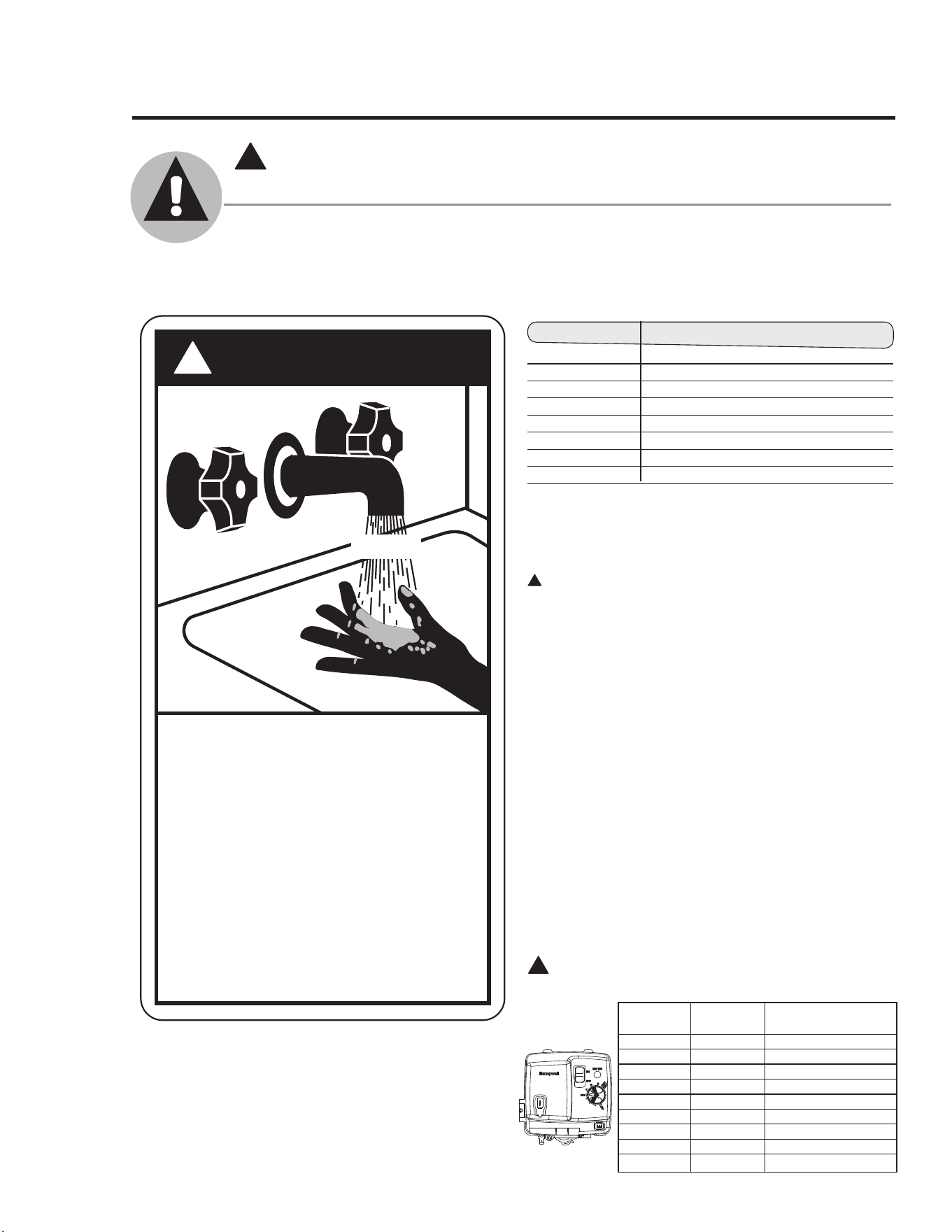
Time/Temperature Relationship in Scalds
Thechartshownabovemaybeusedasaguide
indeterminingtheproperwatertemperatureforyour
home.
DANGER: Households with small children,
disabled, or elderly persons may require a 120°F
(49°C) or lower gas control (thermostat) setting to
prevent contact with “HOT” water.
Maximumwatertemperaturesoccurjustafterthe
burnerhasshutoff.Tofindwatertemperature
beingdelivered,turnonahotwaterfaucetand
placeathermometerinthewaterstreamandread
thethermometer.See"WaterTemperatureSetting"
informationinthe"OperatingtheWaterHeater"
sectionofthismanual.
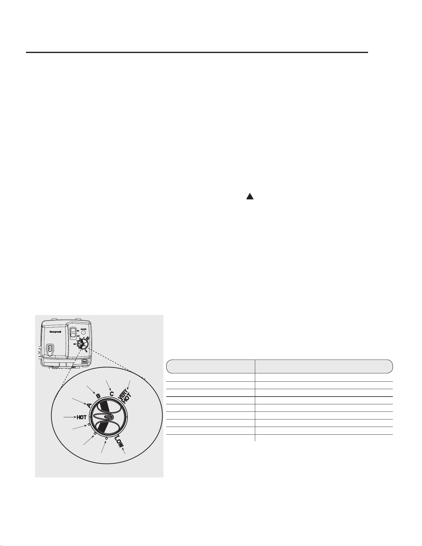
Thetemperatureofthewaterintheheatercanbe
regulatedbysettingthetemperaturedialonthefront
ofthegascontrol(thermostat).Tocomplywith
safetyregulationsthegascontrol(thermostat)was
setatitslowestsettingbeforethewaterheaterwas
shippedfromthefactory.
Thetablebelowdetailstheapproximatewater
temperatureforeachmarkontheGasControl
(Thermostat)TemperatureDial.
D A N G E R
!
HOT
Water temperature over 125°F can
cause severe burns instantly or
death from scalds.
Children, disabled and elderly are
at highest risk of being scalded.
See instruction manual before
setting temperature at water
heater.
Feel water before bathing or
showering.
Temperature limiting valves are
available, see manual.
BURN
!
DANGER!
WATERTEMPERATURESETTING
Safety and energy conservation are factors to be considered when selecting the water
temperature setting of a water heater’s gas control. Water temperatures above 125°F (52°C)
can cause severe burns or death from scalding. Be sure to read and follow the warnings
outlined on the label pictured below. This label is also located on the water heater.
Notice: Mixing valves are available for reducing point
of use water temperature by mixing hot and cold water
in branch water lines. Contact a licensed plumber or the
local plumbing authority for further information.
4
IMPORTANTSAFETYINFORMATION.
READALLINSTRUCTIONSBEFOREUSING.
!
!
DANGER: Hotter water increases the potential for
Hot Water SCALDS.
valveSet
Point
Estimated
Temperature
BurnsonAdultSkin
LOW
90°F(32°C) ------------------------
●
98°F(37°C) ------------------------
●
105°F(40°C) ------------------------
●
113°F(45°C) ------------------------
HOT
120°F(49°C) Morethan5minutes
A
130°F(54°C) About30seconds
B
140°F(60°C) Lessthan5seconds
C
150°F(66°C) About1-1/2seconds
vERYHOT
160°F(71°C) About1/2second
WaterTemperature TimeToProduceaSeriousBurn
49°C (120°F) More than 5 minutes
52°C (125°F) 1
1
/2 to 2 minutes
54°C (130°F) About 30 seconds
57°C (135°F) About 10 seconds
60°C (140°F) Less than 5 seconds
63°C (145°F) Less than 3 seconds
66°C (150°F) About 1
1
/2 seconds
68°C (155°F) About 1 second
TablecourtesyofShrinersBurnInstitute
5
LP and Natural gas have an odorant added to aid in detecting a gas leak. Some people
may not physically be able to smell or recognize this odorant. If you are unsure or
unfamiliar with the smell of LP or natural gas, ask the gas supplier. Other conditions,
such as “odorant fade”, which causes the odorant to diminish in intensity, can also hide or
camouflage a gas leak.
DANGER!
LIqUEFIEDPETROLEUM(LPPROPANE)
ANDNATURALGASMODELS
● Water heaters utilizing LP gas are
different from natural gas models. A
natural gas water heater will not function
safely on LP gas and vice versa.
● No attempt should ever be made to
convert the water heater from natural
gas to LP gas. To avoid possible
equipment damage, personal injury or
fire, do not connect the water heater to a
fuel type not in accordance with the unit
data plate. LP for LP units. Natural gas
for natural gas units. These units are not
certified for any other fuel type.
● LP appliances should not be installed
below grade (for example, in a basement)
if such installation is prohibited by
federal, state and/or local laws, rules,
regulations or customs.
● LP gas must be used with great caution.
It is heavier than air and will collect first
in lower areas making it hard to detect at
nose level.
● Before attempting to light the water
heater, make sure to look and smell for
gas leaks. Use a soapy solution to check
all gas fittings and connections. Bubbling
at a connection indicates a leak that must
be corrected. When smelling to detect a
gas leak, be sure to sniff near the floor
also.
● Gas detectors are recommended in LP
& natural gas applications and their
installation should be in accordance
with the detector manufacturer’s
recommendations and/or local laws,
rules, regulations or customs.
● It is recommended that more than one
method, such as soapy solution, gas
detectors, etc., be used to detect leaks in
gas applications.
!
DANGER: If a gas leak is present or
suspected:
● Donotattempt to find the cause yourself.
● Donot try to light any appliance.
● Donot touch any electrical switch.
● Donot use any phone in your building.
● Leave the house immediately and make
sure your family and pets leave also.
● Leave the doors open for ventilation
and contact the gas supplier, a qualified
service agency or the fire department.
● Stay away from the house (or building)
until the service call has been made, the
leak is corrected and a qualified agency
has determined the area to be safe.
!
6
IMPORTANTSAFETYINFORMATION.
READALLINSTRUCTIONSBEFOREUSING.
!
WARNING!
For your safety, the information in this manual must be followed to minimize the risk of
fire or explosion, electric shock, or to prevent property damage, personal injury, or loss of
life.
Havetheinstallershowyouthelocationofthegasshut-offvalveandhowtoshutitoff
ifnecessary.Turnoffthemanualshut-offvalveifthewaterheaterhasbeensubjectedto
overheating,fire,flood,physicaldamageorifthegassupplyfailstoshutoff.
● Readthismanualentirelybeforeinstalling
oroperatingthewaterheater.
● Usethisapplianceonlyforitsintended
purposeasdescribedinthisUseandCare
Manual.
● Besureyourapplianceisproperlyinstalled
inaccordancewithlocalcodesandthe
providedinstallationinstructions.
● Do not attempttorepairorreplaceanypart
ofyourwaterheaterunlessitisspecifically
recommendedinthismanual.Allother
servicingshouldbereferredtoaqualified
technician.
SAFETYPRECAUTIONS
READANDFOLLOWTHISSAFETYINFORMATION
CAREFULLY.
SAvETHESEINSTRUCTIONS
The water heater should not be located in
an area where leakage from the tank or
connections will result in damage to the area
adjacent to the heater or to lower floors of the
structure.
When such areas cannot be avoided it is
recommended that a suitable catch pan,
adequately drained, must be installed under
the water heater.
The pan must not restrict air flow to the
combustion air inlet openings (perforation
openings) located around the lower perimeter of
the water heater.
Catchpankitsareavailablefromthestorewhere
thewaterheaterwaspurchased,oranywater
heaterdistributor.
When installed in a closet, DO NOT block
or obstruct any of the combustion air inlet
openings located around the perimeter of the
water heater. A minimum of 1” (2.5 cm) is
required between these combustion air inlet
openings and any obstruction.
Makecertainthefloorunderneaththewater
heaterisstrongenoughto
sufficientlysupporttheweightofthewater
heateronceitisfilledwithwater.
Agasfiredwaterheateroranyotherappliance
shouldnotbeinstalled
inaspacewhereliquidswhichgiveoff
flammablevapoursaretobeusedorstored.
Suchliquidsincludegasoline,LPgas(butaneor
propane),paintoradhesivesandtheirthinners,
solventsorremovers.
When installed in a closet, DO NOT block
or obstruct any of the combustion air inlet
openings located around the perimeter of the
water heater. A minimum of 1” is required
between these combustion air inlet openings
and any obstruction.
DO NOT obstruct or block the Flammable
Vapor Sensor.
Becauseofnaturalairmovementinaroomor
otherenclosedspace,flammablevapourscan
becarriedsomedistancefromwhereliquids
whichgiveoffflammablevapoursaretobeused
orstored.Theopenflameofthewaterheater’s
pilotormainburnercanignitethesevapours
andcreateashut down condition of the water
heater which will not allow the water heater
to ignite until examined by a Qualified Service
Technician.
FvIRcertifiedgaswaterheaterscanbeinstalled
onaresidentialgaragefloorwithouttheuseof
an18-inchstandinaccordancewiththeNational
FuelGasCode,NFPA54,ANSIZ223.1,for
USinstallationsandinaccordancewiththe
CAN/CSAB149.1-NaturalGasandPropane
InstallationCodeforCanadianinstallations,
unlessotherwisedirectedbyProvince,Stateand
Localcoderequirements.Thewaterheatermust
belocatedsoitisnotsubjecttophysicaldamage,
forexample,bymovingvehicles,areaflooding,
etc.
● Thewaterheatershouldbeinstalledasclose
aspracticaltothegasventorchimney.
● Hotwaterlinesshouldbeinsulatedtoconserve
waterandenergy.
● Thewaterheaterandwaterlinesshould
beprotectedfromexposuretofreezing
temperatures.
● Do not installthewaterheaterinbathrooms,
bedrooms,anyoccupiedroomsnormallykept
closed,orinunprotectedoutdoorareas.
● Minimumclearancefromcombustible
construction:
IftheclearancesstatedontheInstruction/
WarningLabel,locatedonthefrontofthe
heaterdiffer,installthewaterheateraccording
totheclearancesstatedonthelabel.
● Ifthewaterheateristobeinstalleddirectlyon
carpeting,thewaterheatershallbeinstalled
onametalorwoodpanelextendingbeyond
thefullwidthanddepthofthewaterheaterby
atleast3in.(7.6cm)inalldirectionsor,ifthe
waterheateristobeinstalledinanalcoveor
closet,theentirefloormustbecoveredbya
woodormetalpanel.
Location
!
WARNING: Combustible
construction refers to
adjacent walls and ceilings
and should not be confused
with combustible or
flammable products and
materials. Combustible
and/or flammable products
and materials should never
be stored in the vicinity of
this or any gas appliance.
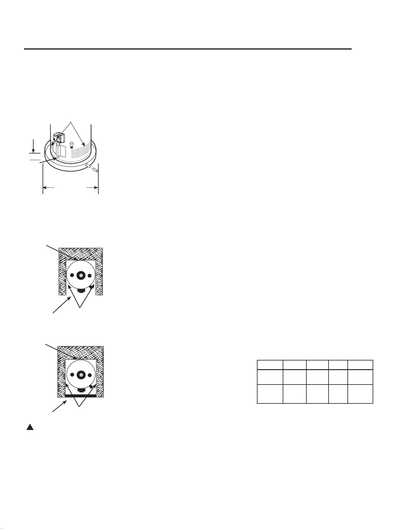
Rear
Sides
FrontOpen
Sides
FrontEnclosed
Top View Closet
Top View Alcove
Rear
7
CombustionAirInlet
Openings
The auxiliary catch pan
installation MUST conform
to local codes.
Diameterof
waterheater
plus2”min.
Max.
2”
Location Front Sides Rear Top
Alcove
3”
(7.62cm)
0”
(0cm)
0”
(0cm)
12”
(30.5cm)
Closet
3”
(7.62cm)
1”
(2.5cm)
0”
(0cm)
12”
(30.5cm)
Installing the water heater
This water heater must be installed in accordance with these instructions, local codes, utility company
requirements, and/or in the absence of local codes, use the latest edition of the American National Standard/
National Fuel Gas Code. A copy can be purchased from either the American Gas Association, 400 N. Capitol Street
NW, Washington, DC 20001 as ANSI standard Z223.1 or National Fire Protection Association, 1 Batterymarch
Park, Quincy, MA 02269 as booklet NFPA 54. For Canada Installations use CAN/CSA B149 - Natural Gas and
Propane Installation Code. A copy can be purchased from the Canadian Standards Association, 5060 Spectrum
Way, Suite 100, Mississauga, Ontario, Canada, L4W 5N6
Fv
Sensor

8
Installing the water heater
Combustion and Ventilation Air
Proper operation of the water heater
requires air for combustion and
ventilation. Provisions for combustion
and ventilation air must comply with
the latest edition of the CAN/CSA
B149.1 Natural Gas and Propane
Installation Code.
When installed in a closet, DO NOT block
or obstruct any of the combustion air inlet
openings located around the perimeter of
the water heater. A minimum of 1” (2.5 cm)
is required between these combustion air
inlet openings and any obstruction.
NOTICE: If the water heater is installed
in an unconfined space within a building
of conventional frame, masonry or metal
construction, infiltration air is normally
adequate for proper combustion and
ventilation. If the water heater is installed in
a confined space, provisions for combustion
and ventilation air must be made.
Aconfinedspaceisonehavingavolume
oflessthan50cubicfeet(1.4cubic
meters)per,1000Btuhoftheaggregate
inputofallapplianceswithinthatspace.
Theairmustbesuppliedthroughtwo
permanentopeningsofequalarea.One
istobelocatedwithin12”(30.5cm)
abovethefloorandtheotheristobe
locatedwithin12”(30.5cm)fromthe
ceiling.
Theminimumnetfreeareaofeachopening
mustnotbelessthanonesquareinch
(6.5sqcm)per1000Btuhofthetotal
inputratingofalltheappliancesinthe
enclosure,(butnotlessthan100sq.in.)
ifeachopeningcommunicateswithother
unconfinedareasinsidethebuilding.
Buildingsofunusuallytightconstruction
shallhavethecombustionandventilation
airsuppliedfromoutdoors,orafreely
ventilatedatticorcrawlspace.
Ifairissuppliedfromoutdoors,directlyor
throughverticalducts,theremustbetwo
openingslocatedasspecifiedaboveand
eachmusthaveaminimumnetfreearea
ofnotlessthanonesquareinch(6.5sq
cm)per4000Btuhofthetotalinputrating
ofalltheappliancesintheenclosure.
Ifhorizontalductsareusedto
communicatewiththeoutdoors,each
openingmusthaveaminimumnetfree
areaofnotlessthanonesquareinch
(6.5sqcm)per2000Btuhofthetotal
inputratingofalltheappliancesinthe
enclosure.Ifductsareused,theminimum
dimensionsofrectangularairductsshall
notbelessthan3”(7.6cm).
NOTICE: If the duct openings which supply
combustion and ventilation air are to be
covered with a protective screen or grill,
the net free area (openings in the material)
of the covering material must be used
in determining the size of the openings.
Protective screening for the openings MUST
NOT be smaller than 1/4” (0.64 cm) mesh to
prevent clogging by lint or other debris.
Corrosive Atmospheres
Theairinbeautyshops,drycleaning
establishments,photoprocessing
labs,andstorageareasforliquidand
powderedbleachesorswimmingpool
chemicalsoftencontainsuchhalogenated
hydrocarbons.
Anairsupplycontaininghalogenated
hydrocarbonsmaybesafetobreathe,
butwhenitpassesthroughagasflame
corrosiveelementsarereleasedthat
willshortenthelifeofanygasburning
appliance.
Propellantsfromcommonspraycans
orgasleaksfromA/Candrefrigeration
equipmentarehighlycorrosiveafter
passingthroughaflame.
Thewaterheaterwarrantyisvoidedwhen
failureoftheheaterisduetooperationin
acorrosiveatmosphere.
NOTICE: The water heater
should not be installed near
an air supply containing
halogenated hydrocarbons.
Inspect Shipment
Carefullyinspectthewaterheaterfordamagebeforeproceedingwiththeinstallation.
Ofspecificinterestshouldbeanydentsordamagetothedrafthoodand/orfluedamper
assembly.Ifyoufinddamage,DONOTinstallorattemptanyrepairtothewaterheater.
Contactthemanufacturerasdetailedunder"IFYOUNEEDSERvICE"sectionofthis
manual.
9
Thermal Expansion
Determine if a check valve exists in the inlet
water line. Check with your local water
utility company. Itmayhavebeeninstalled
inthecoldwaterlineasaseparatebackflow
preventer,oritmaybepartofapressure
reducingvalve,watermeterorwatersoftener.
Acheckvalvelocatedinthecoldwaterinlet
linecancausewhatisreferredtoasa“closed
water system”.Acoldwaterinletlinewithno
checkvalveorbackflowpreventiondeviceis
referredtoasan“open”watersystem.
Aswaterisheated,itexpandsinvolumeand
createsanincreaseinthepressurewithinthe
watersystem.Thisactionisreferredtoas
“thermal expansion”.Inan“open”water
system,expandingwaterwhichexceedsthe
capacityofthewaterheaterflowsbackinto
thecitymainwherethepressureiseasily
dissipated.
A“closed water system”,however,prevents
theexpandingwaterfromflowingbackintothe
mainsupplyline,andtheresultof“thermal
expansion”cancreatearapidanddangerous
pressureincreaseinthewaterheaterand
systempiping.Thisrapidpressureincreasecan
quicklyreachthesafetysettingoftherelief
valve,causingittooperateduringeachheating
cycle.Thermalexpansion,andtheresulting
rapid,andrepeatedexpansionandcontraction
ofcomponentsinthewaterheaterandpiping
systemcancauseprematurefailureoftherelief
valve,andpossiblytheheateritself.Replacing
thereliefvalvewill notcorrecttheproblem!
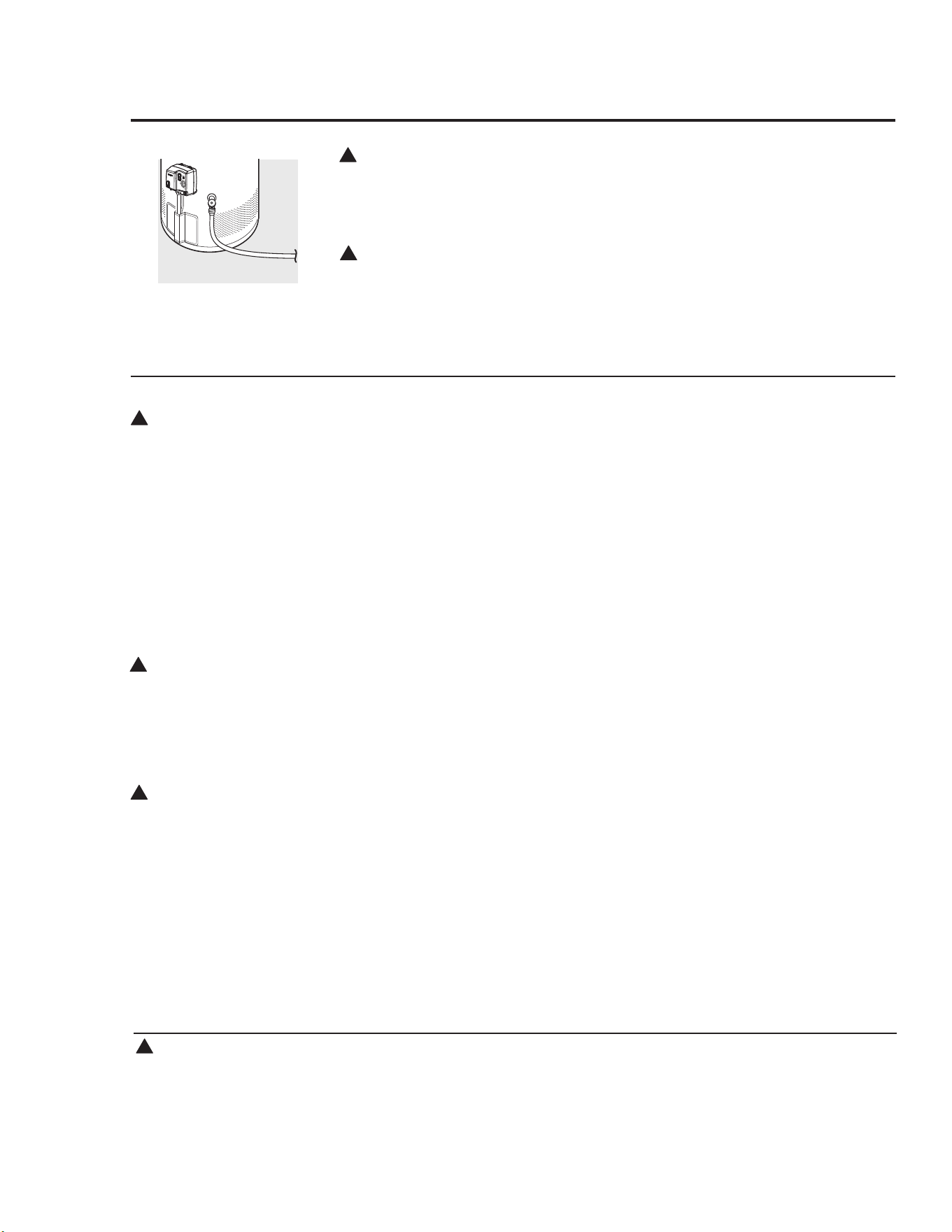
Thesuggestedmethodofcontrollingthermal
expansionistoinstallanexpansiontankin
thecoldwaterlinebetweenthewaterheater
andthecheckvalve(seeillustrationbelow).
Theexpansiontankisdesignedwithanair
cushionbuiltinthatcompressesasthesystem
pressureincreases,therebyrelievingtheover
pressureconditionandeliminatingtherepeated
operationofthereliefvalve.Othermethods
ofcontrollingthermalexpansionarealso
available.Contactyourinstallingcontractor,
watersupplierorplumbinginspectorfor
additionalinformationregardingthissubject.
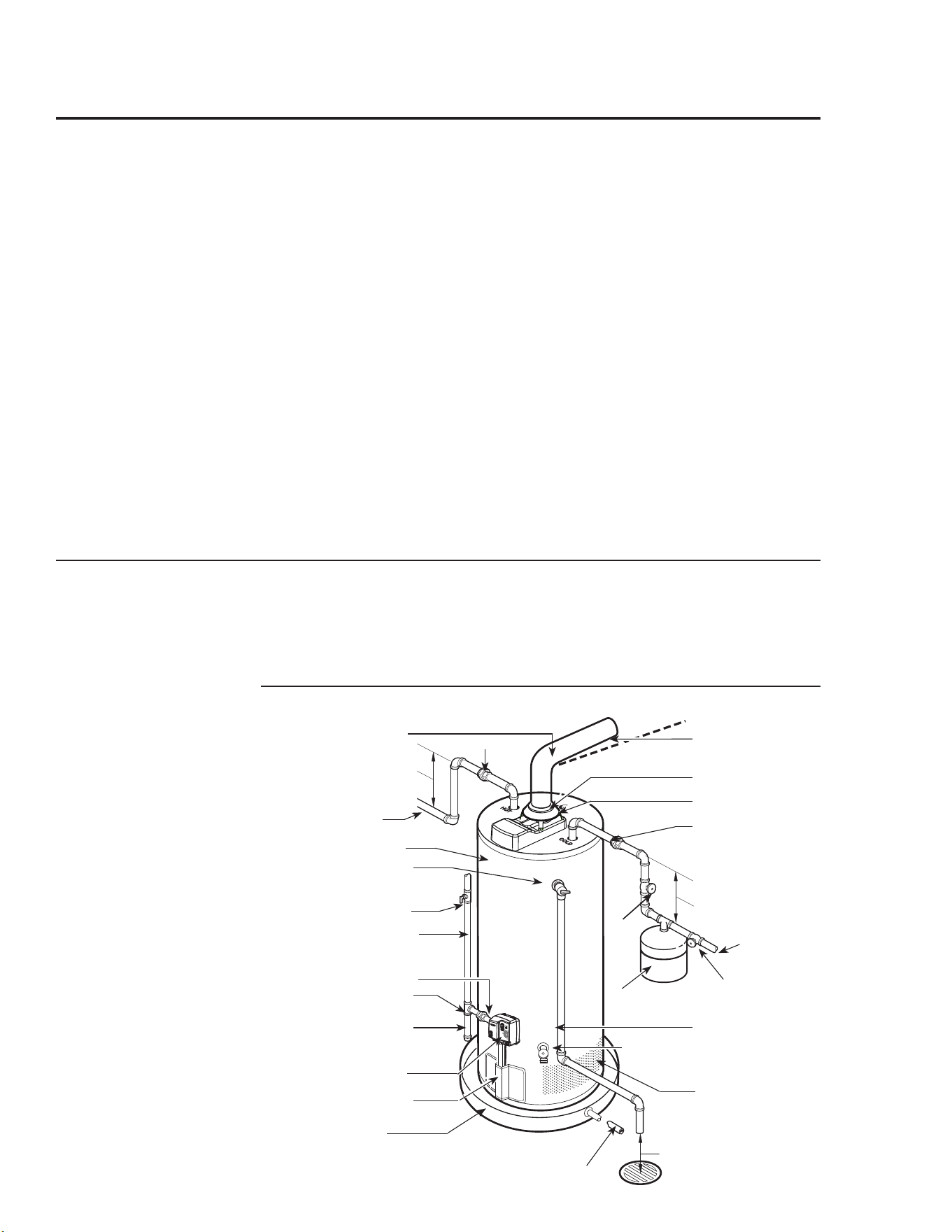
Typical Installation
Refertotheillustrationbelowforsuggested
typicalinstallation.Theinstallationofunions
orflexiblecopperconnectorsisrecommended
onthehotandcoldwaterconnectionssothat
thewaterheatermaybeeasilydisconnected
forservicingifnecessary.TheHOTandCOLD
waterconnectionsareclearlymarkedandare
3/4”NPTonallmodels.Installashut-offvalve
inthecoldwaterlinenearthewaterheater.
Water Supply Connections
IMPORTANT: Do not
apply heat to the HOT or
COLD water connections. If
sweat connections are used,
sweat tubing to adapter
before fitting adapter to the
cold water connections on
heater. Any heat applied
to the cold water supply
fittings will permanently
damage the dip tube.
NOTICE: The Canadian
Standards Association
mandates a manual gas
shut off valve: See CSA
B149- Installation Code for
complete instructions.
When Pex water piping
is used do not connect
pex directly to the tank.
A minimum 12" (31cm)
copper pipe at the tank
inlet and outlet connections
must be used.
Heattrap
6”minimum
Heattrap
6”minimum
Union
Togassupply
Sedimenttrap
Cap
Groundjointunion
DrainPanPipe
tosuitabledrain.
Drain
valve
Reliefvalvedischarge
linetosuitableopen
drain.
Tocoldwater
supply
6”Airgap
Drafthood
Pitchup1/4”
perfoot
Auxiliarycatchpan
Union
Anode
Manualgasshut-off
Thermostaticgasvalve
Jacketdoor
Temperatureand
pressurereliefvalve
Shut-offvalve
Shut-off
valve
Thermalexpansion
tank(ifrequired)
CombustionAir
InletOpenings
Hotwateroutletto
fixtures
WaterHeaterJacket
ventconnectorto
chimney
10
Installing the water heater
A new combination temperature and pressure relief valve, complying with the Standard for Relief Valves
and Automatic Gas Shut-Off Devices for Hot Water Supply Systems, ANSI Z21.22/CSA 4.4, is supplied
and must remain in the opening provided and marked for the purpose on the water heater. No valve of
any type should be installed between the relief valve and the tank. where applicable, local codes shall
govern the installation of relief valves.
Relief Valve
Thepressureratingofthereliefvalve
mustnotexceed150psi(1034kPa),the
maximumworkingpressureofthewater
heaterasmarkedontheratingplate.
TheBtuhratingofthereliefvalvemust
equalorexceedtheBtuhinputofthe
waterheaterasmarkedonitsratingplate.
Positiontheoutletofthereliefvalve
aboveasuitableopendraintoeliminate
potentialwaterdamage.Pipingused
shouldbeofatypeapprovedforhotwater
distribution.
Thedischargelinemustbenosmaller
thantheoutletofthevalveandmust
pitchdownwardfromthevalvetoallow
completedrainage(bygravity)ofthe
reliefvalveanddischargeline.
Theendofthedischargelineshouldnot
bethreadedorconcealedandshouldbe
protectedfromfreezing.Novalveof
anytype,restriction,orreducercoupling
shouldbeinstalledinthedischargeline.
To Fill the Water Heater
Makecertainthatthedrainvalveis
closed,thenopentheshut-offvalveinthe
coldwatersupplyline.
Openeachhotwaterfaucetslowlyto
allowtheairtoventfromthewater
heaterandpiping.
Asteadyflowofwaterfromthehotwater
faucet(s)indicatesafullwaterheater.
Donotallowtheflammablevaporsensor
tobecomesubmergedinwater.
WARNING: The tank
must be full of water before
heater is turned on. The
water heater warranty does
not cover damage or failure
resulting from operation
with an empty or partially
empty tank.
Condensation
Condensationcanformonthetank
whenitisfirstfilledwithwater.
Condensationmightalsooccurwitha
heavywaterdrawandverycoldinlet
watertemperatures.
Dropsofwaterfallingontheburnercan
produceasizzlingorpingingsound.
Thisconditionisnotunusual,andwill
disappearafterthewaterbecomesheated.
If,however,thecondensationcontinues,
examinethepipingandfittingsfor
possibleleaks.
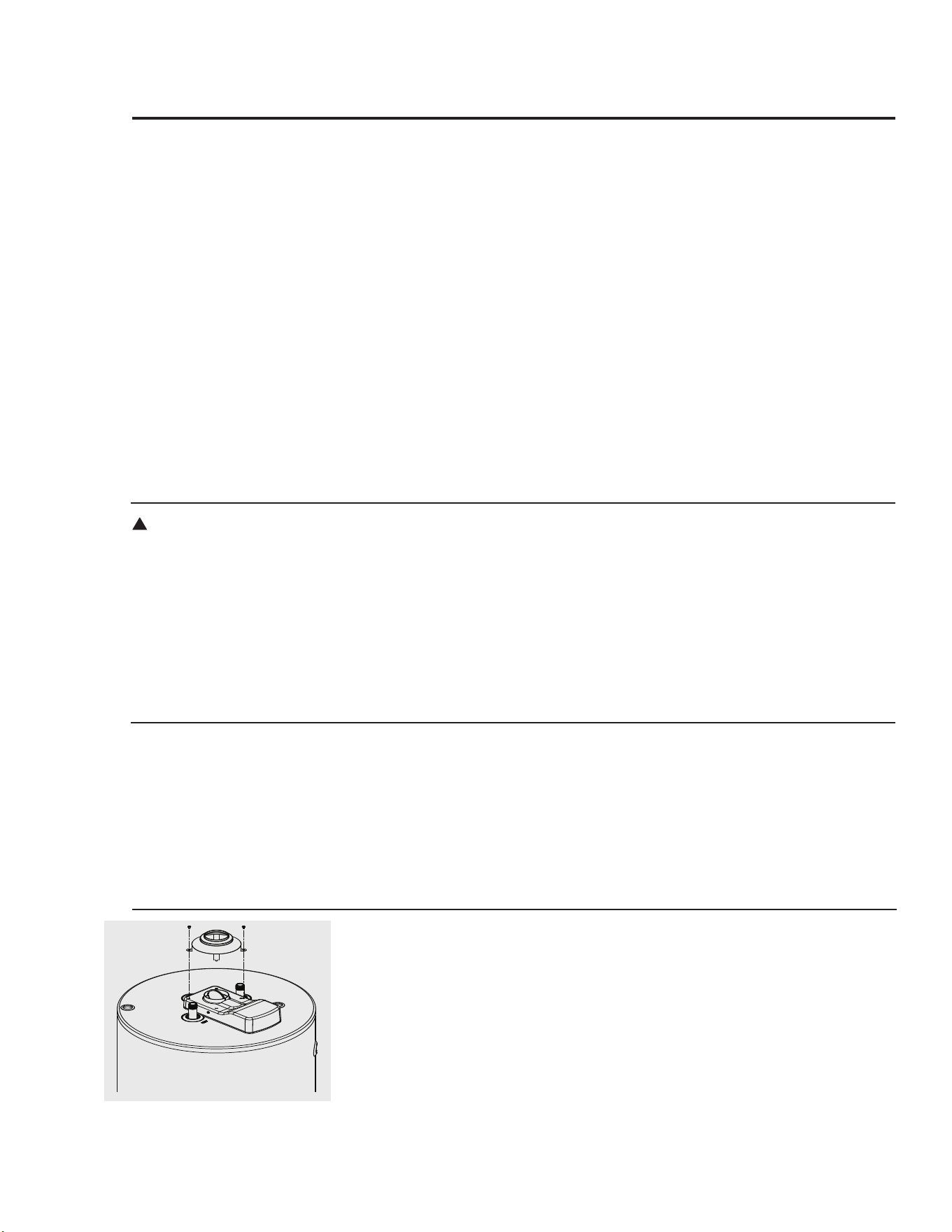
!
Thiswaterheaterhasafactoryinstalled
fluedamperdeviceforincreasedenergy
efficiency.Removalofthefluedamper
connectionswillrendertheheater
inoperable.Donotoperatethewater
heaterwithoutthedamperhousingin
placeonthedamperassembly.Adraft
hoodisshippedwiththiswaterheater.
Thedrafthoodmustbeinstalledonthe
damperhousingusingtheholesprovided
foralignmentandfastening.Thedamper
mustbeinopenpositionasshowninthe
figurewhenwaterheatermainburner
isoperating.Seetroubleshooting
instructionsifaconditionotherthanthis
occurs.
Flue Damper
Follow these instructions for proper installation and operation
11
WARNING: Do not
attempt to convert this
water heater for use with
a different type of gas
other than the type shown
on the rating plate. Such
conversion could result
in hazardous operating
conditions.
Leak Testing
Thewaterheateranditsgasconnections
mustbeleaktestedatnormaloperating
pressuresbeforeitisplacedinoperation.
Turnonthemanualgasshut-off
valvenearthewaterheater.
Useasoapywatersolutiontotestfor
leaksatallconnectionsandfittings.
Bubblesindicateagasleakthatmust
becorrected.
Thefactoryconnectionstothegas
control(thermostat)shouldalsobeleak
testedafterthewaterheaterisplacedin
operation.
High Altitude
Gas Supply
Thebranchgassupplylinetothewater
heatershouldbecleanproperlysized
blacksteelpipeorotherapprovedgas
pipingmaterial.
AunionorANSIdesigncertifiedsemi-
rigidorflexiblegasapplianceconnector
shouldbeinstalledinthegaslinecloseto
thewaterheater.TheCanadianStandards
Associationmandatesamanualgasshut
offvalve:SeeCSAB149-Installation
Codeforcompleteinstructions.
Ifflexibleconnectorsareused,the
maximumlengthshallnotexceed
36"(91.4cm)andmustmeetthe
requirementsinANSIZ21.24/CSA6.10-
ConnectorsforGasAppliances.
Compoundusedonthethreadedjointsof
thegaspipingmustbeofthetyperesistant
totheactionofLPgas.Usecompound
sparinglyonmalethreadsonly.
Whereasedimenttrapisnotincorporated
aspartoftheappliance,asedimenttrap
shallbeinstalleddownstreamofthe
equipmentshutoffvalveasclosetothe
inletoftheapplianceaspracticalatthe
timeoftheapplianceinstallation.
Donotuseexcessiveforce(over31.5
ftlbs.)(42.7Nm)intighteningthepipe
jointatthegascontrol(thermostat)inlet,
particularlyifteflonpipecompoundis
used,asthevalvebodymaybedamaged.
Theinletgaspressuretothewater
heatermustnotexceed14.0in.w.c.(3.5
kPa)w.c.fornaturalgas,andLPgas.
Forpurposesofinputadjustment,the
minimuminletgaspressure(withmain
burneron)isshownonthewaterheater
ratingplate.Ifhighorlowgaspressures
arepresent,contactyourgassupplierfor
correction.
WARNING: Never use
an open flame to test for
gas leaks, as property
damage, personal injury, or
death could result.
WARNING: Failure
to install a water heater
suitable for the altitude at
the location it is intended
to serve, can result in
improper operation of
the appliance resulting
in property damage and/
or, producing carbon
monoxide gas, which could
result in personal injury,
or death.
Thiswaterheaterissuitableandcertified
touseathighaltitude.Refertothe
altitudeinformationonthewaterheater
ratinglabelformaximumallowable
installationaltitude.
!
!
!
Pressure Testing the Gas Supply System
Thewaterheateranditsindividualshut
offvalvemustbedisconnectedfromthe
gassupplypipingsystemduringany
pressuretestingofthatsystemattest
pressuresinexcessof1/2psi(3.5kPa).
Thewaterheatermustbeisolatedfrom
thegassupplypipingsystembyclosing
it'sindividualmanualshutoffvalve
duringanypressuretestingofthegas
supplypipingsystemattestpressures
equaltoorlessthan1/2psi(3.5kPa)
Installing the water heater
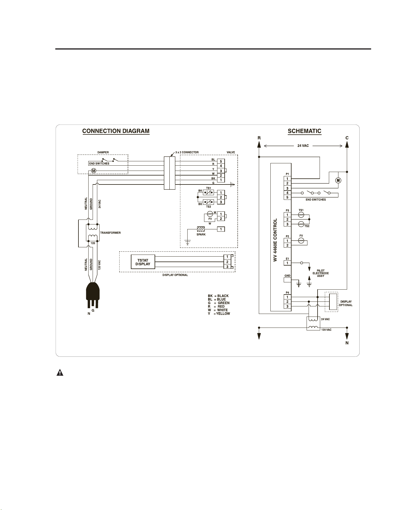
Wiring Diagram
CAUTION! Label all wires prior to disconnection when servicing controls. Wiring errors can cause
improper and dangerous operation. VERIFY PROPER OPERATION AFTER SERVICING!
This water heater is factory installed with a 3-pin 24VAC wall transformer. A 19 feet long length of wire is provided
for easy access to an outlet. Do not use an extension cord for powering this water heater. If the supplied power
cord is insufficient to reach a power outlet, a 30 foot power cord assembly is available as an accessory. Contact the
service department to obtain and replace the power cord assembly that was shipped with the heater.
12
H
H

13
The water heater must be installed with the factory supplied draft hood in place.
Venting
ventconnectorsmustbeattachedtothe
drafthoodoutlettoconnectthewater
heatertothegasventorchimney.The
ventconnectorsmustbethesamesize
(diameter)asthedrafthoodorlarger,
neversmaller.
Forproperventingincertaininstallations
alargerventconnectorsizemaybe
needed.Itisrecommendedthatadouble
wallB-ventconnectorbeusedfor
ventingpurposes.Refertotheventing
requirementsinCAN/CSAB149.1Natural
GasandPropaneInstallationcodefor
additionalinformation.
Horizontalventconnectorsmustbe
pitchedupwardtothechimneyatleast
1/4”perlinearfoot(2.1cmpermeter).
Singlewallventconnectorsmustbeat
least6”(15cm)fromadjacentunprotected
combustiblesurface.ventjointsmustbe
securelyfastenedbysheetmetalscrewsor
otherapprovedmethod.
Testforspillageatthedrafthoodrelief
openingafter5minutesofmainburner
operation.Useaflameofamatchor
candleorsmoke.Theflameorsmoke
shouldbepulledintothedrafthood’s
reliefopening(s).Iftheflameorsmoke
isnotpulledintothedrafthood'srelief
opening,shutoffthewaterheaterand
makeproperadjustments/repairstothe
ventingsystem.
Insulation Blankets
Insulationblankets,availabletothe
generalpublic,forexternaluseongas
waterheatersarenotnecessary.The
purposeofaninsulationblanketisto
reducethestandbyheatlossencountered
withstoragetankheaters.Thiswater
heatermeetsorexceedstheCSAstandards
requirementsforenergyefficiency,with
respecttoinsulationandstandbyloss
requirementsmakinganinsulationblanket
unnecessary.
Themanufacturer’swarrantydoesnot
coveranydamageordefectcausedby
installation,attachmentoruseof
anytypeofenergysavingorother
unapproveddevices(otherthanthose
authorizedbythemanufacturer)into,onto
orinconjunctionwiththewaterheater.
Theuseofunauthorizedenergysaving
devicesmayshortenthelifeofthewater
heaterandmayendangerlifeandproperty.
DANGER: Failure to
install the draft hood and
properly vent the water
heater to the outdoors as
outlined in the Venting
section of this manual will
result in unsafe operation
of the water heater causing
bodily injury, explosion,
fire or death. To avoid the
risk of fire, explosion, or
asphyxiation from carbon
monoxide, NEVER operate
the water heater unless
it is properly vented and
has adequate air supply
for proper operation as
outlined in the Venting
section of this manual.
WARNING: If local codes
require external application
of insulation blanket
kits the manufacturer’s
instructions included with
the kit must be carefully
followed.
!
!
DO
❑ DO check inlet gas pressure to ensure
thatitiswithintherangespecifiedonthe
ratingplate.
❑DO provideadequateairforcombustion
and ventilation as discussed in the Use
andCareManualand the National Fuel
GasCode.
❑DO maintain proper clearances to
combustibles as specified on the rating
plate.
❑DO ensure that the venting system
complies with the guidelines found in
theUseandCareManual andSection7
of
CAN/CSA B149Natural Gas and
PropaneInstallationCode
❑DO contactaqualifiedservicetechnician
if thepilot or main burner will notstay
lit. The burner chamber is designed to
be sealed utilizing a gasket and tamper
resistantscrews.
❑DO ensure that the flue damper is not
obstructedandisfreeofdebris.
DON’T
❑DON’T blockorrestrictCombustionAir
InletOpenings locatedaroundthelower
portionofthewaterheaterjacket.
❑DON’T removetheBurnerAccessDoor
unlessabsolutelynecessary.Thisshould
only be done by a qualified service
technician. A new burner access door
gasket must be installed on any burner
accessdoorthathasbeenremoved.
❑ DON’T install this water heater where
standingwatermayoccur.
❑DON’T operate the water heater if the
sightglassorburneraccessdoorgrommet
isdamagedorbroken.
❑ DON’T manually open or close the
damper.
14
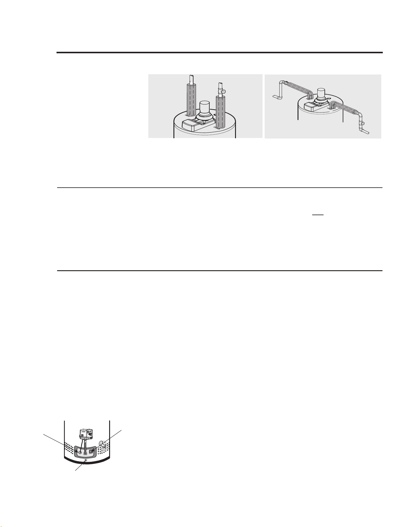
Forincreasedenergyefficiency,some
waterheatershavebeensuppliedwith
two24”(61cm)sectionsofpipe
insulation.
Installtheinsulation,accordingtothe
illustrationsabove,thatbestmeetsyour
requirements.
During Installation of this water heater...........
Heat Trap
Hot and Cold Pipe Insulation Installation
Forincreasedenergyefficiency,some
waterheatershavebeensuppliedwith
factoryinstalled3/4”NPTheattrapsin
thehotoutletlineandcoldwaterinlet
line.
Theseheattrapsmayrequireaminimum
ofone(1)90° 3/4”NPTelbowandmay
requireanadditional90° 3/4”NPTelbow
ora3/4”couplingdependingonyour
installationneeds.SeeIllustrationof
nipplesandheattrapsinthe"Replacement
Parts"sectionofthismanual.
Typical vertical piping arrangement
Typical horizontal piping arrangement
BurnerAccess
DoorGrommet
SightGlass
Flammable
vaporSensor
Installing the water heater

15
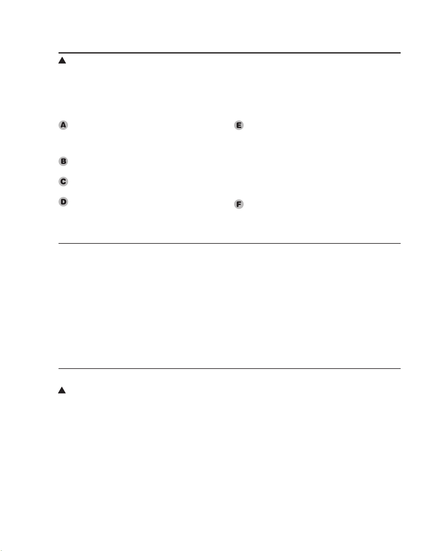
Installation Checklist
A. Water Heater Location
B. Water Supply
C. Gas Supply
D. Relief Valve
E. Venting
❑ Closetoareaofvent.
❑ Indoorsandprotectedfromfreezing
temperatures.
❑ Proper clearance from combustible surfaces
observed and water heater not installed on
carpetedfloor.
❑ Sufficientfreshairsupplyforproperoperationof
waterheater.
❑ Air supply free of corrosive elements and
flammablevapours.
❑ Provisions made to protect area from water
damage.
❑ Sufficientroomtoserviceheater.
❑ Combustiblematerials,suchasclothing,cleaning
materials,rags,etc.clearofthebaseoftheheater.
❑ Clearances of 1”
(2.5 cm)
from combustion
airinletopeningsobserved.
❑ Flammablevapoursensorisnotblocked.
❑ Waterheatercompletelyfilledwithwater.
❑ Airpurgedfromwaterheaterandpiping.
❑ Waterconnectionstightandfreeofleaks.
❑ Gaslineequippedwithshut-offvalve,unionand
sedimenttrap.
❑ Approvedpipejointcompoundused.
❑ Soap and water solution used to check all
connectionsandfittingsforpossiblegasleak.
❑ GasCompanyinspectedinstallation(ifrequired).
❑ TemperatureandPressureReliefvalveproperly
installedanddischargelineruntoopendrain.
❑ Dischargelineprotectedfromfreezing.
❑ Fluebaffleproperlyhungintopofheater’sflue.
❑ Drafthoodproperlyinstalledondamperhousing.
❑ ventconnector(s)pitchedupwardtochimney
(¼"perlinearfootoflengthminimum)(2.1cm
permeter).
❑ ventconnector(s)securelyfastenedtogetherwith
screws.
❑ Singlewallventconnector(s)atleast6”
(15
cm)
fromcombustiblematerial.
F. Wiring
❑ Correctpowersupply(24vAC)transformer.
❑ Electricalconnectiontight.
❑ Heater properly grounded and proper polarity
observed.
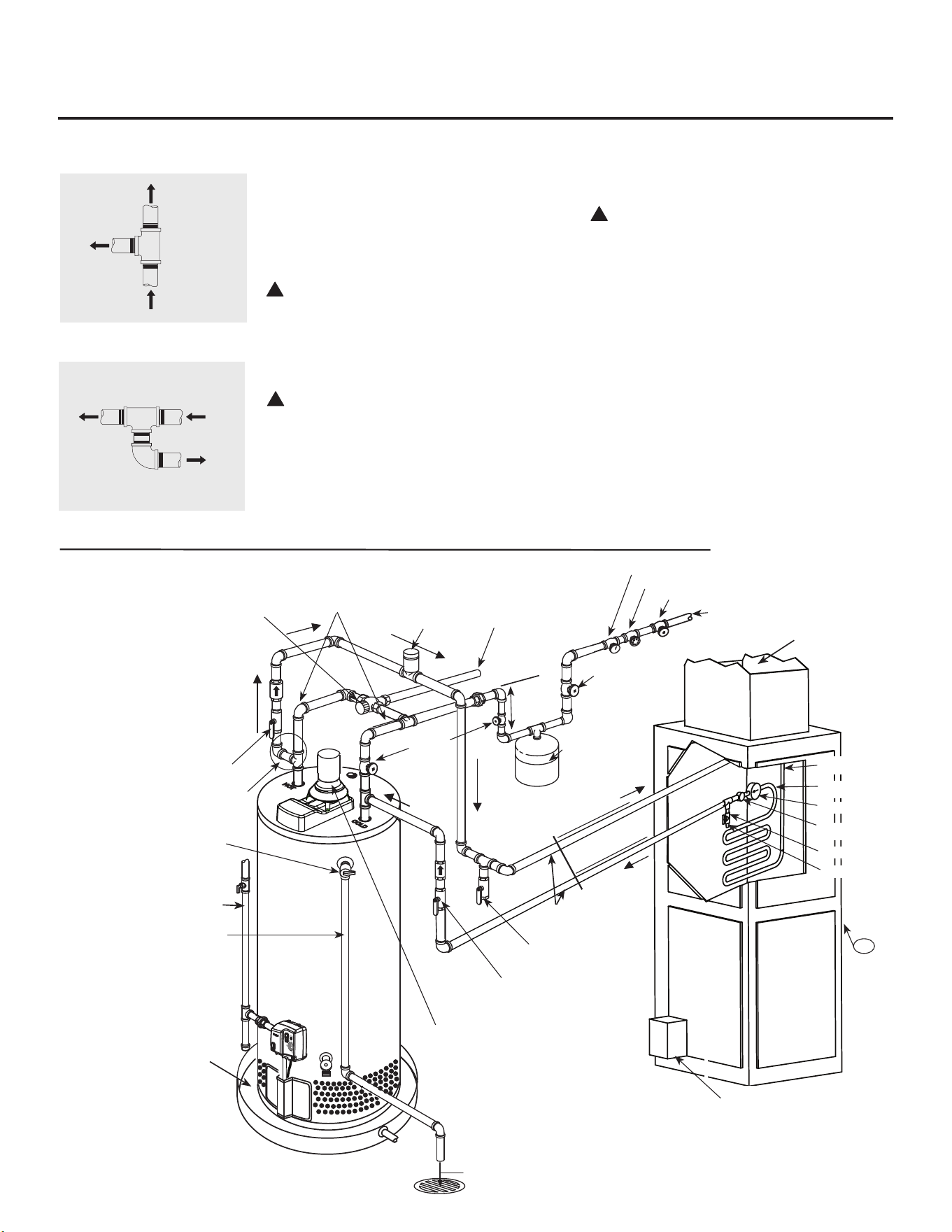
Tee fitting for vertical hot
water supply lines.
Hot water
supply to
house
From HOT
outlet on
water heater
Hot water
supply to
heating
unit
Supplemental instructions for gas water heaters installed in
potable/space heating applications.
Local codes or plumbing authority requirements may vary from the instructions or diagrams provided in this
manual and take precedent over these instructions.
Tee fitting for horizontal hot
water supply lines.
From HOT
outlet on
water heater
Hot water
supply to
house
Hot water supply
to heating unit
Combination Potable and Space Heating Application
Teefittingmustbeinstalledasshown.This
ensuresthatanyairinthewaterlineswillbe
purgedthroughthedomesticwaterfaucetsand
showers.
DANGER: When this system requires
water for space heating at elevated
temperatures (above 125°F [52°C.]), a mixing
or tempering valve must be installed in the
hot water supply line to the house in order to
reduce the scald hazard potential.
DANGER: Any piping or components used
in the installation of this water heater in
a combination potable and space heating
application must be suitable for use with
drinking water.
DANGER
: If this water heater is installed
in an application intended to supply
domestic hot water needs and hot water
for space heating purposes, do not connect
the heater to an existing heating unit or
components of a heating system that have
previously been used with a non drinking
water system. Toxic chemicals such as those
used for boiler treatment may be present
and will contaminate the drinking water
supply causing possible health risks. Never
introduce toxic chemicals, such as those used
for boiler treatment, into this system.
16
!
!
!
Typical Piping Diagram for Combination Potable/Space Heating Installation
Springloadedcheckvalveinheatingunit
hotwatersupplylineandcoldwaterreturn
line(notsuppliedwithwaterheater)
NOTE:Thischeckvalveisincorporated
insomeheatingunits.Refertothe
installationinstructionssuppliedwith
specificheatingunittodetermineifitis
required.
Isolationvalvein
coldwaterreturnline
fromheatingunit(not
suppliedwithwater
heater)
Nominal3/4"sizemixingortemperingvalve
(refertowarningabove).Followmixingor
temperingvalvemanufacturer’sinstructionsfor
installationofthevalve.
Temperatureandpressurerelief
valvedischargeline
AirHandler
Drainvalve
(notsuppliedwith
waterheater)
Hotwater
tospaceheater
TemperatureandPressureRelief
valve,tietolocationapprovedby
localcode
Seediagramsaboveforproper
pipeapplicationforvertical
orhorizontalsupplylines.
Isolationvalveinhotwatersupplyline
toheatingunit(notsuppliedwithwater
heater)
3/4"coldwatersupply
3/4"Tempered
domestichotwater
supplytohouse.
Gaslinetowaterheater
6”AirGap
CombustionAirInlet
Openings
2GallonThermal
ExpansionTank(if
required-notsupplied
withwaterheater)
Airvent
HeatTrap
6”Min.
3/4"Shut-Offvalve(Typ.)
3/4"Checkvalvewith1/8"Hole
PressureGauge
3/4"Shut-Offvalve(Typ.)
3/4"Shut-
Offvalve
(Typ.)
Pipingloopbetweenwater
heaterandfancoilshall
beflowguardgoldCPvC
orequal
Hotwatercoil
Allbronzepump.
Checkvalve
internalinpump.
Airbleedvalve.
WaterSampleTap.
T
FAN
ON
OFF
HEAT
COOL
ToHvACUnit.
Electronicallycontrolledpumptimer.
Activatesevery6hoursfor60seconds.
Wiretobronzepump.
3/4"HWS&HWR
toHeatingCoil.
Minimumof2'-0"developedlengthof
3/4"type"L"copperfromthewater
heaterconnection.
WaterHeaterdrainpaninstalledin
accordancewiththeLocalandState
Code
GasFired
WaterHeater
ventdischargemust
complywithCAN/CSA
B149.1
120°to130°
140°
16
17
Lighting the water heater
Before operating this water heater, be sure to read and follow the instructions on the label pictured
below and all other labels on the water heater, as well as the warnings printed in this manual. Failure to
do so can result in unsafe operation of the water heater resulting in property damage, personal injury,
or death . Should you have any problems reading or following the instructions in this manual, STOP,
and get help from a qualified person.
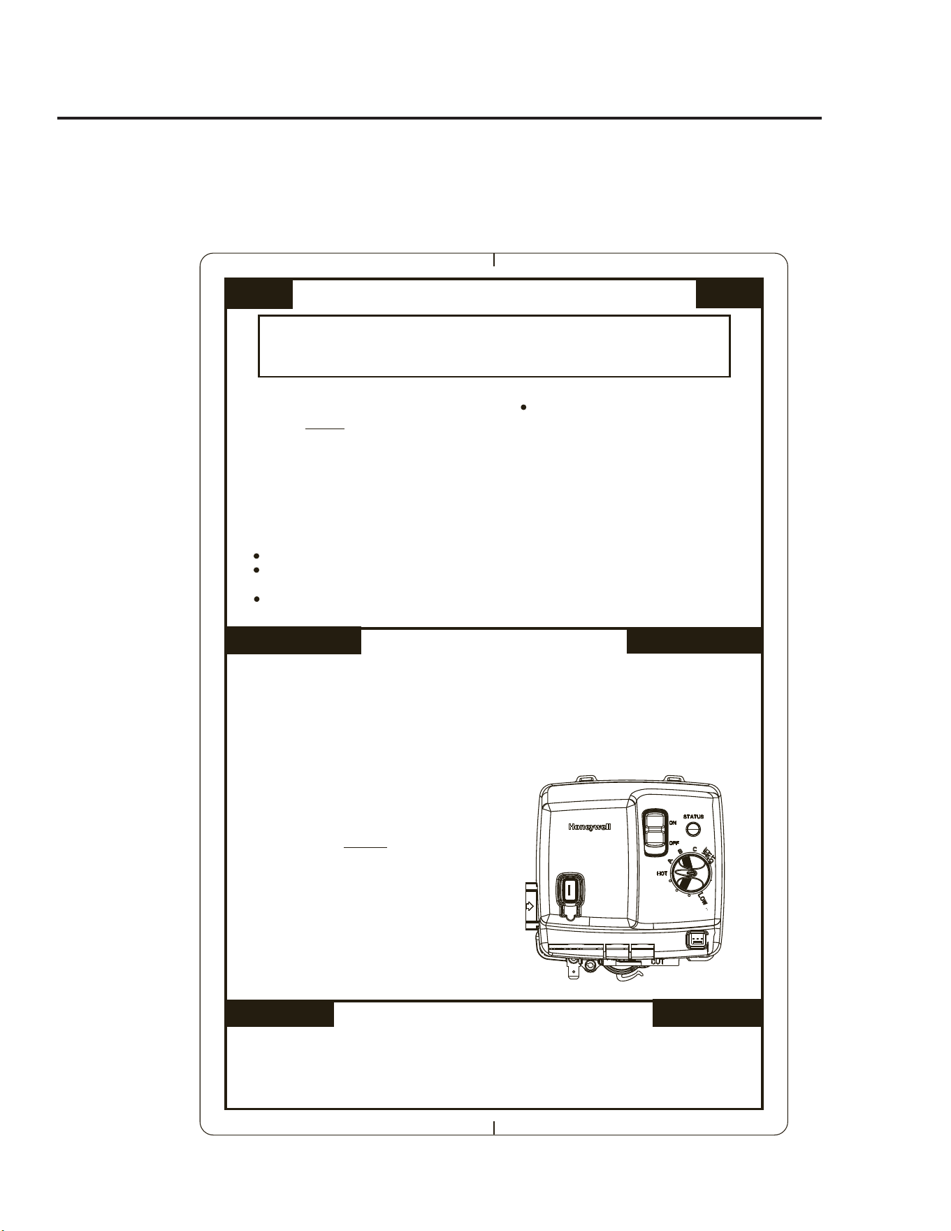
FOR YOUR SAFETY READ BEFORE OPERATING
OPERATING INSTRUCTIONS
TO TURN OFF GAS TO APPLIANCE
If you cannot reach your gas supplier,
call the fire department.
instuctions.
C.
Do not use this appliance if any part has
been under water. Immediately call a
qualified installer or service agency to
replace a flooded water heater. Do not
attempt to repair the unit! It must be
replaced!
Use only your hand to turn the thermostat
dial. Never use tools. If the dial will
not turn by hand, do not try to repair it,
call a qualified service technician. Force
or attempted repair may result in fire or
explosion.
D.
9.
10.
STOP! Read the safety information above
on this label.
Set the thermostat dial to the lowest
setting
Slide the “ON/OFF” switch located on
the gas control to the “OFF” position.
Turn off all electric power to the
appliance.
This appliance is equipped with an
ignition device which automatically
lights the pilot. DO NOT attempt to light
the pilot by hand.
Wait five (5) minutes to clear out any gas.
If you smell gas, STOP! Follow “B’ in the
safety inf
ormation above on this label. If
you do not smell gas, go to the next step.
Turn on electric power to the appliance.
Slide the ”ON/OFF” switch located on
the gas control to the “ON” position.
1.
3.
2.
1.
2.
3.
4.
5.
6.
7.
8.
Immediately call your gas supplier from a
neighbor’s phone. Follow the gas suppliers
Do not try to light any appliance.
Do not touch any electric switch; do not
use any phone in your building.
WHAT TO DO IF YOU SMELL GAS
This appliance is equipped with an
ignition device which automatically lights
the pilot. DO NOT try to light the pilot by
hand.
A.
BEFORE PUTTING THIS APPLIANCE INTO
SERVICE - Smell all around the appliance
area for gas. Be sure to smell next to the
floor because some gas is heavier than air
and will settle on the floor.
B.
Set the thermostat dial to the desired
setting.
If the appliance will not operate,
follow the instructions “TO TURN OFF
GAS TO APPLIANCE” and call your
service technician or gas supplier.
Set the thermostat dial to the lowest setting.
Slide the “ON/OFF” switch located on the gas control to the “OFF” position.
Turn off all electric power to the appliance if service is to be performed.
4.
Close the manual gas shut-off valve.
WARNING: If you do not follow these instructions and use the Use & Care
Manual instructions exactly, a fire or explosion may result causing property damage,
personal injury or loss of life.
18
SafetyPrecautions
Do turnoffmanualgasshut-offvalveifwaterheater
hasbeensubjectedtooverheating,fire,flood,
physicaldamageorifthegassupplyfails
toshutoff.
DoNot turnonwaterheaterunlessitiscompletely
filledwithwater.
Do Not turnonwaterheaterifcoldwatersupply
shut-offvalveisclosed.
Do Not allowcombustiblematerialssuchas
newspaper,ragsormopstoaccumulatenear
waterheater.
Do Not storeorusegasolineorotherflammable
vapoursandliquids,suchasadhesivesorpaint
thinner,invicinityofthisoranyotherappliance.
Ifsuchflammablesmustbeused,opendoors
andwindowsforventilation,andallgasburning
appliancesinthevicinityshouldbeshutoffincluding
theirpilotburners,toavoidvapourslighting.
NOTICE: Flammable vapours can be drawn by air
currents from surrounding areas to the water heater.
Ifthereisanydifficultyinunderstandingorfollowing
theOperatingInstructionsortheCareandCleaning
section,itisrecommendedthataqualifiedpersonor
servicemanperformthework.
Operating the water heater
CAUTION: Hydrogen gas can be produced in a hot water system served by this water heater that has not been used for a
long period of time (generally two weeks or more). HYDROGEN GAS IS EXTREMELY FLAMMABLE!! To dissipate such
gas and to reduce risk of injury, it is recommended that the hot water faucet be opened for several minutes at the kitchen sink
before using any electrical appliance connected to the hot water system. If hydrogen is present, there will be an unusual sound
such as air escaping through the pipe as the water begins to flow. Do not smoke or use an open flame near the faucet at the
time it is open.
DANGER: Hotter water
increases the Potential
for Hot Water SCALDS
.
Households with small
children, disabled, or elderly
persons may require a 120°F
(49°C) or lower gas control
(thermostat) setting to
prevent contact with HOT
water.
Water Temperature Setting
Thetemperatureofthewaterinthewater
heatercanberegulatedbysettingthe
temperaturedialonthefrontofthegas
control(thermostat).
Safetyandenergyconservationarefactors
tobeconsideredwhenselectingthewater
temperaturesettingofthewaterheater’s
gascontrol(thermostat(s)).Thelowerthe
temperaturesetting,thegreaterthesavings
inenergyandoperatingcosts.
Tocomplywithsafetyregulations,thegas
control(thermostat)wassetatitslowest
settingbeforethewaterheaterwasshipped
fromthefactory.Therecommended
startingpointtemperatureis120°F(49°F).
Watertemperaturesabove125°F(52°C)
cancausesevereburnsordeathfrom
scalding.Besuretoreadandfollowthe
warningsoutlinedinthismanualandon
thelabellocatedonthewaterheaternear
thegascontrolthermostat.
Mixingvalvesareavailableforreducing
pointofusewatertemperaturebymixing
hotandcoldwaterinbranchwater
lines.Contactalicensedplumberor
thelocalplumbingauthorityforfurther
information.(Seepage4formoredetails.)
Thechartonthenextpagemaybeused
asaguideindeterminingtheproperwater
temperatureforyourhome.
!
!
Thiswaterheaterisequippedwithan
ignitiondevicewhichautomatically
lightsthepilot.Donottrytolightthe
pilotbyhand.Oninitialstart-up,itis
recommendedthattheouterdoorbe
removed(leaveinnerdoorinplacefor
safety)todetermineifthepilotandmain
burnerareoperatingproperly.
Oncefilledwithwater,pluginthe
electricalsupplycordandslidethe“ON/
OFF”switchlocatedonthefrontofthe
combinationgascontroltothe“ON”
position.Setthethermostatdialtothe
desiredsetting.
Afterthepilotandmainburnerignite,
replacetheouterdoor.Ifnopilotand
mainburnerflamesareestablished,the
combinationgascontrolwillgothrough
threetrialsforignitionbeforegoinginto
a“lock-out”mode.Awarninglightwill
alerttheuserofthis“lock-out”mode
condition.Ifthishappens,refertothe
“GasvalveLEDcodes”sectionofthis
manual.
Operating Procedure
19
Water Temperature Setting…
90° F
113°F
98°F
105°F
120°F
130°F
140°F
150°F
160°F
Temperatures are approximate
Time/Temperature Relationship in Scalds
WaterTemperature TimeToProduceaSeriousBurn
120°F(49°C) Morethan5minutes
125°F(52°C) 1
1
/2to2minutes
130°F(54°C) About30seconds
135°F(57°C) About10seconds
140°F(60°C) Lessthan5seconds
145°F(63°C) Lessthan3seconds
150°F(66°C) About1
1
/2seconds
155°F(68°C) About1second
TablecourtesyofShrinersBurnInstitute
Thefollowingisadditionalinformation
whichaidindeterminingasafeworking
temperaturetomeeteachhouseholdneed.
Maximumwatertemperaturesoccurjust
aftertheburnerhasshutoff.Todetermine
thewatertemperature,turnonahotwater
faucetandplaceathermometerinthe
waterstream.
Aconditionknownas“stacking”or“layer-
ing”canoccurwhenaseriesofshortand
frequenthotwaterdrawsaretaken.
Thehottesttemperaturewaterwillbeat
thetopofthetank,closesttotheoutlet
pipedeliveringhotwatertothehome.
Stackingcancausethistoplayerofwater
tobehotterthanthewatertowardthebot-
tomofthetanknearthegascontrol(ther-
mostat).Therefore,alwaysrememberto
testthewatertemperaturewithyourhand
beforeuseandrememberthathotterwater
increasestheriskofscaldinjury.
Also,alwayssuperviseyoungchildrenor
otherswhoareincapacitated.
Thegascontrol(thermostat)isconstructed
withabuiltinsafetyshutoffdevice
designedtoshutoffthegassupplytothe
burnerifthemainburnerisextinguished
foranyreason.
Thegascontrol(thermostat)isalso
equippedwithagasshutoffdevicethat
willshutoffthegassupplytotheburnerif
thewaterheaterexceedsnormaloperating
temperatures.Refertothe“BeforeYou
CallForService”sectionofthismanual,
orcontactyourdealer.
!
WARNING: Should overheating
occur or the gas supply fail to shut off,
turn off the manual gas control valve to
the appliance
NOTICE: Replace any part of the gas
control system which has been under
water.
Ifthewaterheaterhasbeensubjectedto
re,oodorphysicaldamage,turnoffthe
manualgascontrol(shutoff)valveanddo
notoperatethewaterheateragainuntilit
hasbeencheckedbyaqualiedservice
technician.
20
Care and cleaning of the water heater
Draining the Water Heater
CAUTION: To shut off gas to the water
heater, slide the ON/OFF switch on the
thermostat control to the "off" position.
Also, shut off the gas on the gas supply line
at the manual gas shutoff before draining the
water heater.
DANGER: Before manually operating
the temperature and pressure relief valve,
make certain no one will be exposed to the
hot water released by the valve. The water
drained from the tank may be hot enough
to present a scald hazard and should be
directed to a suitable drain to prevent injury
or damage.
Beforeturningoffthecoldwatersupplyto
thewaterheater,openahotwaterfaucet
allowingsufficientcoldwaterintothe
tanktopreventtheriskofascaldinjury
whiledrainingthewaterheater.Oncethe
waterinthetankisnolongerhot,turnoff
thecoldwatersupplytothewaterheater.
Openahotwaterfaucetorliftthehandle
onthereliefvalvetoadmitairtothetank.
Attachagardenhosetothedrain
valveonthewaterheateranddirect
thestreamofwatertoadrain.Open
thedrainvalve.
Housekeeping
vacuumaroundthebaseofthewater
heaterfordust,dirtandlintonaregular
basis.visuallyinspectpilotburnerand
relightifnecessary.
Toensuresufficientventilationand
combustionairsupply,properclearances
mustbemaintained.
DO NOT
block or obstruct any of the
combustion air inlet openings located
around the perimeter of the water heater. A
minimum of 1” (2.5 cm) is required between
these combustion air inlet openings and any
obstruction.
Routine Preventative Maintenance
Properlymaintained,yourwaterheater
willprovideyearsofdependabletrouble-
freeservice.
Itisrecommendedthataperiodic
inspectionofthegascontrol(thermostat),
burner,reliefvalve,internalflue-wayand
ventingsystemshouldbemadebyservice
personnelqualifiedingasappliancerepair.
Itissuggestedthataroutinepreventative
maintenanceprogrambeestablishedand
followedbytheuser.
Periodically,liftandreleasethelever
handleonthetemperaturepressurerelief
valve,locatednearthetopofthewater
heater,tomakecertainthevalveoperates
freely.Allowseveralgallonstoflush
throughthedischargelinetoanopendrain.
NOTICE: If the temperature and
pressure relief valve on the hot water
heater discharges periodically, this
may be due to thermal expansion in a
closed water system. Contact the water
supplier or your plumbing contractor on
how to correct this. DO NOT plug the
relief valve outlet.
Awaterheater’stankcanactasasettling
basinforsolidssuspendedinthewater.
Itisthereforenotuncommonforhard
waterdepositstoaccumulateinthebottom
ofthetank.Ifallowedtoaccumulate,
thesesolidscancoverthegascontrol
(thermostat)sensors,causingthesensorsto
operateerratically.Becauseaccumulated
solidscanpreventthegascontrol
(thermostat)sensorsfromaccurately
readingthewatertemperature,thewater
atthefixturecanbehotterthanthegas
control(thermostat)dialsetting.Itis
suggested thatafewlitersofwaterbe
drainedfromthewaterheater’stankevery
monthtocleanthetankofthesedeposits.
Rapidclosingoffaucetsorsolenoidvalves
inautomaticwaterusingappliancescan
causeabangingnoiseheardinawater
pipe.Strategicallylocatedrisersinthe
waterpipesystemorwaterhammer
arrestingdevicescanbeusedtominimize
theproblem.
Theanoderodshouldberemovedfromthe
waterheater’stankannuallyforinspection
andreplacedwhenmorethan6”(15cm)
ofcorewireisexposedateitherendofthe
rod.
Makesurethecoldwatersupplyisturned
offbeforeremovinganoderod.
Thiswaterheaterincorporatesa
combustionshutoffdevicethatshuts
theoperationofthewaterheaterdown
ifundesirablecombustionconditions
occur.Suchasthepresenceofflammable
vapoursorblockageofthecombustionair
inletopenings.Pleasecontactaqualified
servicetechnicianifthisoccurs.
DANGER: Before
manually operating the
relief valve, make certain
no one will be exposed to
the danger of the hot water
released by the valve. The
water may be hot enough to
create a scald hazard. The
water should be released
into a suitable drain to
prevent injury or property
damage.
DANGER: Combustible
materials, such as clothing,
cleaning materials, or
flammable liquids, etc., must
not be placed against or next
to the water heater.
DANGER: Failure to
perform the recommended
Routine Preventative
Maintenance can harm the
proper operation of this
water heater, which can cause
carbon monoxide dangers,
excessive
hot water temperatures and
other potentially hazardous
conditions.
DANGER: Hotter water
increases the potential for
Hot Water Scalds.
!
!
!
!
!
!
21
Venting System Inspection
Thewaterheater’sinternalfluemustbe
inspectedperiodicallytobecertainitis
cleanbyremovingthefluedamper,draft
hood,andfluebaffle.
Whenreinstallingthefluebafflemake
certainitishungsecurelybyitscollarat
thetopoftheflueway.
Reinstallthedamperandthedrafthood.
Inspectthegasventingsystemand/orthe
chimney.
Makecertaintheventconnectorfromthe
drafthoodtothetheventsystemand/or
thechimneyisproperlypositionedand
securelyattached.
Ifafterinspectionoftheventsystem
youfindsootordeterioration;
callthelocalgasutilitytocorrectthe
problemandcleantheflue,orreplace
thefluebaffle,andventingsystembefore
resumingoperationofthewaterheater.
Testforspillageatthedrafthoodrelief
openingafter5minutesofburner
operation.Useaflameofamatchor
candleorsmoke.Theflameorsmoke
shouldbepulledintothedrafthood’s
reliefopening(s).Iftheflameorsmoke
isnotpulledintothedrafthood'srelief
opening,shutoffthewaterheaterand
makeproperadjustments/repairstothe
ventingsystem.
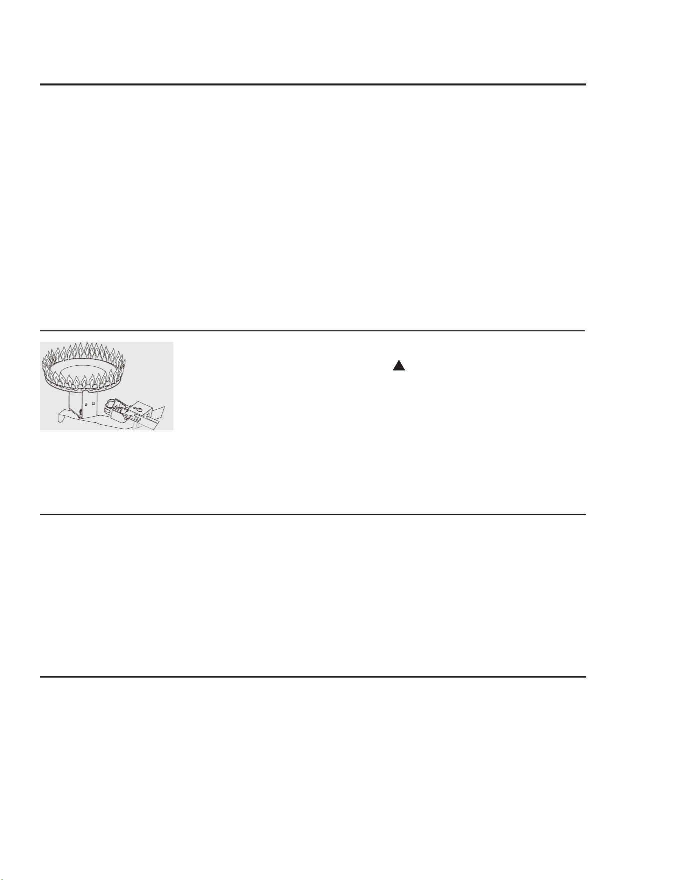
Burner Inspection
visuallyinspectthepilotburnerandmain
burnerannually.
Throughthesiteglass,inspectthepilot
burnerflamewiththemainburneroffand
inspectthemainburnerwhilefiring.
Ifanyunusualburneroperationisnoted,
thewaterheatershouldbeshutoff
untilqualifiedserviceassistancecanbe
obtained.
CAUTION: For your safety, cleaning
of the burner must be performed only by
qualified service personnel. The burner
chamber is a sealed area. If the burner
access door is removed, the burner access
door gasket must be replaced.
Forcleaning,removetheburnerfromthe
waterheater.Avacuumcleanercanbe
usedontheburnerandfloorshieldinside
thewaterheater.Theburnercanalsobe
cleanedbyscrubbingwithmilddetergent.
Proper burner and pilot burner
pattern.
Vacation and Extended Shut-Down
Ifthewaterheateristoremainidleforan
extendedperiodoftime,thepowerand
watertotheapplianceshouldbeturnedoff
toconserveenergyandpreventabuild-up
ofdangeroushydrogengas.
Thewaterheaterandpipingshouldbe
drainediftheymightbesubjectedto
freezingtemperatures.
Afteralongshut-downperiod,the
waterheater’soperationandcontrols
shouldbecheckedbyqualifiedservice
personnel.Makecertainthewaterheater
iscompletelyfilledagainbeforeplacingit
inoperation.
NOTICE: Refer to the
Hydrogen Gas Caution in the
Operating Instructions.
Anode Rod
Thiswaterheaterisequippedwithan
anoderoddesignedtoprolongthelife
oftheglasslinedtank.Theanoderodis
slowlyconsumed,therebyeliminatingor
minimizingcorrosionoftheglasslined
tank.
Watersometimescontainsahighsulfate
and/ormineralcontentandtogetherwith
cathodicprotectionprocesscanproduce
ahydrogensulfide,orrotteneggodorin
theheatedwater.Chlorinationofthewater
supplyshouldminimizetheproblem.
NOTICE: Do not remove
the anode rod from the water
heater’s tank, except for
inspection and/or replacement,
as operation with the anode
rod removed will greatly
shorten the life of the glass
lined tank and will exclude
warranty coverage.
!
22
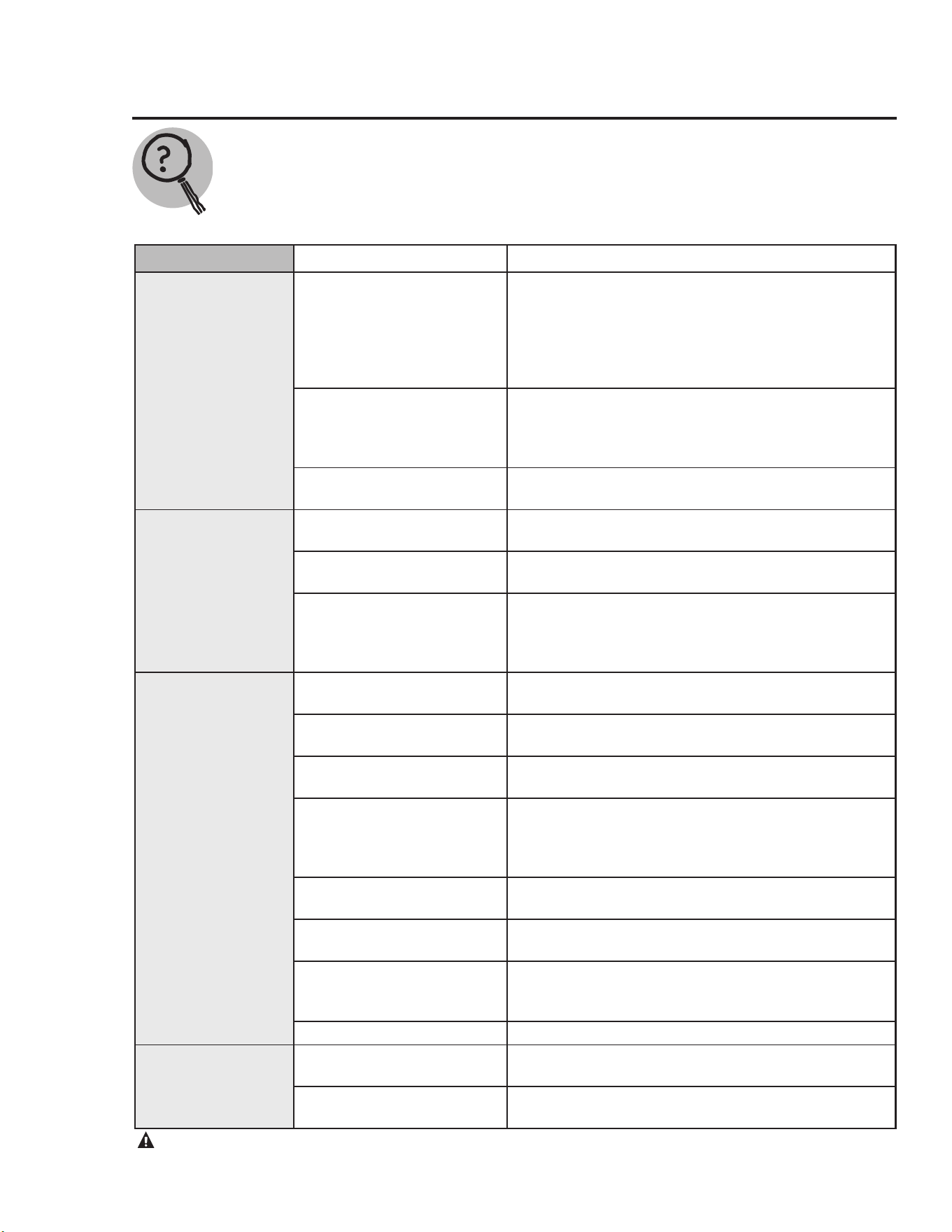
Before You Call For Service…
Troubleshooting Tips
Save time and money! Review the charts on the following pages first and you may not need to call for service.
Thiswaterheaterincorporatesacombustionshutoffdevicethatshutstheoperationofthewaterheater
downifundesirablecombustionconditionsoccur.Suchasthepresenceofflammablevapoursorblockage
ofthecombustionairinletopenings.PleasecontactaqualifiedServiceTechnicianifthisoccurs.
CAUTION: For your safety DO NOT attempt repair of gas piping, gas control (thermostat), burners, vent connectors,
dampers, or other safety devices. Refer repairs to qualified service personnel.
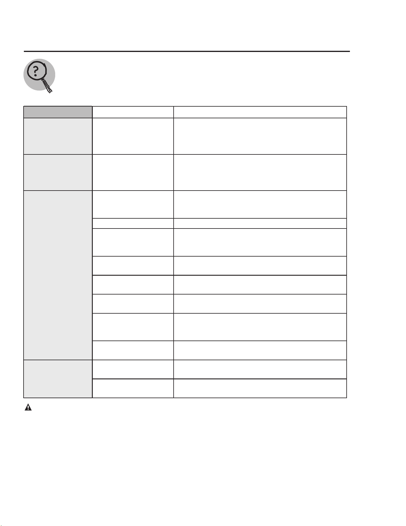
Problem Possible Causes What To Do
Condensation
Thisusuallyhappenswhena
newheaterislledfortherst
time
• Thisisnormal.Afterthewaterinthetankwarms
up,thecondensationwilldisappear.If,however,the
conditionpersists,examinethepipingandttingsfor
possibleleaks.Refertothe"Condensation"informa-
tioninthe"InstallingtheWaterHeater"sectionofthis
manual.
Moisturefromtheproductsof
combustioncondensingonthe
tanksurface.
• Thisisnormalandwilldisappearintime.Excessive
condensationcancausemainburneroutage.Referto
the"Condensation"informationinthe"Installingthe
WaterHeater"sectionofthismanual.
Anundersizedwaterheaterwill
causecondensation.
• Useawaterheatersizethatmeetstherequirementsof
yourneeds.
Yellow flame
or soot
Scaleontopoftheburner. • Contactaqualiedservicetechniciantocleanthe
burner.
Flueorcombustionairinlet
openingsarerestricted.
• Removeobstructionordebrisfromueorcombustion
airinletopeningsonwaterheaterjacket.
Notenoughcombustionorven-
tilationairsuppliedtothewater
heaterlocation.
• Properoperationofthewaterheaterrequiresairfor
combustionandventilation.Refertothe"Combustion
andventilationAir"informationinthe"Installingthe
WaterHeater"sectionofthismanual.
Unable to light
main burner
Airingasline. • Contactaqualiedservicetechniciantopurgeairfrom
thegasline.
Pilotburneroriceclogged. • Pilotshouldbecleanedorreplacedbyaqualiedser-
vicetechnician.
Pilotburnertubepinchedor
clogged.
• Thepilotburnershouldbecleaned,repaired,orre-
placedbyaqualiedservicetechnician.
Damperunabletoopen. • Contactaqualiedservicetechniciantoevaluate
damper.
• Referto"GasvalveErrorCodes"inthe"Gasvalve
LEDCodes"sectionofthismanual.
Wireconnection(s)notfully
secured.
• Contactaqualiedservicetechniciantoconrmwire
connection(s).
Combustionshut-offdevice
tripped.
• Combustionshut-offdeviceshouldbeinspectedbya
qualiedservicetechnician.
Gascontrol(thermostat)prob-
lem.
• Contactaqualiedservicetechnician.
• Referto"GasvalveErrorCodes"inthe"Gasvalve
LEDCodes"sectionofthismanual.
Nopoweratthevalve. • Plugintransformertowalloutlet.
Main burner does
not stay lit.
Combustionshut-offdevice
tripped.
• Combustionshut-offdeviceshouldbeinspectedbya
qualiedtechnician.
Gascontrol(thermostat)shut-
offdevicetripped.
• Contactaqualiedservicetechnician.
23
Before You Call For Service…
Troubleshooting Tips
Save time and money! Review the charts on the following pages first and you may not need to call for service.
This water heater incorporates a combustion shut off device that shuts the operation of the water heater
down if undesirable combustion conditions occur, such as the presence of flammable vapors or blockage
of the combustion air inlet openings. Please contact a Qualified Service Technician if this occurs.
CAUTION: For your safety DO NOT attempt repair of gas piping, gas control (thermostat), burners, vent connectors,
dampers, or other safety devices. Refer repairs to qualified service personnel.
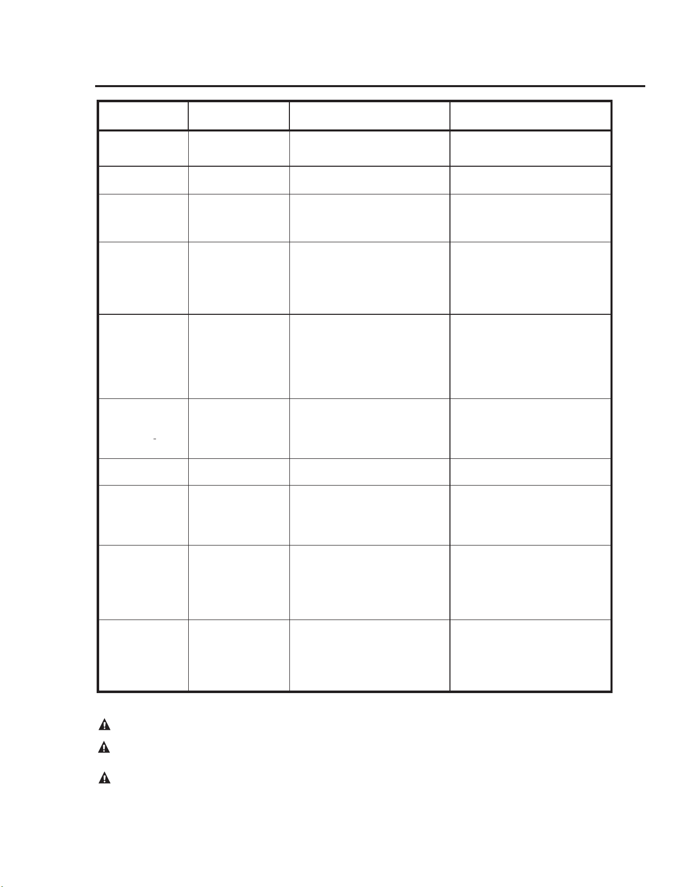
Problem Possible Causes What To Do
Rumbling noise
Scaleandsediment • Drainthewaterheatertoremovescaleandsediment
fromthetank.Referto"DraintheWaterHeater"
informationinthe"CareandCleaningoftheWater
Heater"sectionofthismanual.
Relief valve
producing popping
noise or draining
Pressurebuildupcaused
bythermalexpansiontoa
closedsystem.
• Thisisanunacceptableconditionandmustbecor-
rected.Contactthewaterheatersupplierorplumb-
ingcontractoronhowtocorrectthis.Donotplug
thereliefvalveoutlet.
Not enough or no hot
water
Waterusagemayhave
exceededthecapacityof
thewaterheater.
• Waitforthewaterheatertorecoverafteranabnor-
maldemand.
Lowgaspressure • Checkgassupplypressureandmanifoldpressure.
Thegascontrol(thermo-
stat)maybesettoolow.
• Refertothe"WaterTemperatureSetting"informa-
tioninthe"InstallingtheWaterHeater"sectionof
thismanual.
Leakingoropenhotwa-
terfaucets.
• Makesureallfaucetsareclosed.
Checkvalveerrorcodes. • Refertothe"GasvalveErrorCodes"informationin
the"GasvalveLEDCodes"sectionofthismanual.
"ON/OFF"switchturned
off.
• Turn"ON".
Gascontrol(thermo-
stat)shut-offdevicehas
tripped.
• Contactaqualiedservicetechnician.
Combustionshut-off
systemtripped.
• Contactaqualiedservicetechnician.
Water is too hot
Gascontrol(thermostat)
issettoohigh.
• Seethe"WaterTemperatureSetting"inthe"Install-
ingtheWaterHeater"sectionofthismanual.
Gascontrol(thermostat)
isdefective.
• Contactaqualiedservicetechniciantoreplacethe
gascontrol(thermostat).
24
Gas Valve LED Codes
CAUTION: Make certain power to water heater is “OFF” before removing protective cover FOR ANY REASON.
CAUTION: Label all wires prior to disconnection when servicing controls. Wiring errors can cause improper and
dangerous operation. VERIFY PROPER OPERATION AFTER SERVICING.
CAUTION: For your safety DO NOT attempt repair of gas piping, remote control, burners, vent connectors or other
safety devices. Refer repairs to qualified service personnel.
GAS VALVE LED STATUS/PROBLEM PROBABLE CAUSE SOLUTION
Shortashonceev-
eryfourseconds
NormalOperating
Condition/NoFault
Condition
WaterTemperaturesetpointhasbeen
achieved
Nonerequired
“Heartbeat”,alter-
natesbright/dim
CallingForHeat/No
FaultConditions
Watertemperatureisbelowsetpoint
andburnerison
Nonerequired
OneFlash,three
secondpause
Controlstilloperating/
Lowamesignal
• Pilottuberestrictedordamaged
• Carbonbuild-uponpilot'selectrode
• Pilotigniterwiredamaged
• Gassupplyproblems
• ReplacePilotassembly
• Correctgassupply
TwoFlashes,three
secondpause.
SyteminLockout/Flue
DamperSwitchclosed
• FlueDamperimproperlysealed
• FlueDamperswitchstuckclosed
• FaultyFlueDampermotor
• Obstructionordebrisindamper
opening
• InspectFlueDamperwiringand
connections
• ReplaceFlueDamperAssembly
• Contactaqualiedservicetechni-
cian.See"IFYOUNEEDSER-
vICE"onpage28
ThreeFlashes,three
secondpause
SysteminLockout/Flue
DamperSwitchopen
• FlueDamperimproperlyinstalled
• FlueDamperswitchstuckopen
• FaultyFlueDamperswitch
• Incorrectwiringand/orconnections
• FaultyFlueDampermotor
• Obstructionordebrisindamper
opening
• Inspectwiringandconnections
• ReplaceFlueDamperAssembly
• Contactaqualiedservicetechni-
cian.See"IFYOUNEEDSER-
vICE"onpage28
FourFlashes,three
secondpause
SysteminLockout/
ThermalCutoffDevice
tripped
• ThermalwellfaultinGasControl
(Thermostat)
• GasControl(Thermostat)faulty
• Tanknotlledwithwater
• ResetGasControl(Thermostat)and
checkforpropercyclingofcontrol.
• ReplaceGasControl(Thermostat)
• Ensuretankiscompletelylled
withwater
FiveFlashes,three
secondpause
SysteminLockout/No
FlameSense
Pilotand/orMainBurnervalvehas
failedtoopen
ReplacetheGasControl(Thermostat)
Six-OneFlashes,
threesecondpause
SysteminLockout/
Unitfailedtolight
• Pilotameunstable
• Pilottuberestrictedordamaged
• Carbonbuild-uponpilot'selectrode
• Pilotigniterwiredamged
• Gassupplyproblem(s)
• ReplacePilotassembly
• Correctgassupply
Six-TwoFlashes,
threesecondpause
SysteminLockout/
FlueDamperSwitch
opened
• ImproperFlueDamperinstallation
• FaultyFlueDamperswitch
• Incorrectwiringand/orconnections
• InspectFlueDamperwiringand
connections
• ReplaceFlueDamperAssembly
• Contactaqualiedservicetechni-
cian.See"IFYOUNEEDSER-
vICE"onpage28
Six-ThreeFlashes,
threesecondpause
SysteminLockout/
FlameLost
• Combusstionairsupplyrestricted
orblocked
• Pilottuberestrictedordamaged
• Carbonbuild-uponpilot'selectrode
• Pilotigniterwiredamaged
• Gassupplyproblem(s)
• Ensurecombustionairsupplyisnot
blockedorrestricted
• ReplacePilotassembly
• Correctgassupply
25
GAS VALVE LED STATUS/PROBLEM PROBABLE CAUSE SOLUTION
Six-FourFlashes,
threesecondpause
SysteminLockout/
Flamesenseoutof
sequence
GasControl(Thermostat's)valve
stuckopen
ReplaceGasControl(Thermostat)
SevenFlashes,three
secondpause
SysteminLockout/
PresenceofFlamma-
blevaporsdetected
• Gasolineorotherammable
vapor(s)weredetected
• FaultyFlammablevaporSensor
• FaultyGasControl(Thermo-
stat)
• Ensurethatnoammablevapor(s)
arepresent
• ResettheGasControl(Thermostat)
using"ON/OFF"switchlocatedon
thefrontofthecontrol
• ReplaceFlammablevaporSensor
• ReplaceGasControl(Thermostat)
Eight-OneFlash,
threesecondpause
SysteminLockout/
Flammablevapor
Sensorfaultdetected
• Flammablevaporsensorvalues
outofrange
• ImproperFlammableva-
porSensorwiringand/or
connection(s)
• FaultyFlammablevaporSensor
• InspecttheFlammablevaporSen-
sorwiringandconnection(s)
• ReplaceFlammablevaporSensor
• ReplaceGasControl(Thermostat)
Eight-TwoFlashes,
threesecondpause
SysteminLockout/
Energycutoffdevice
faultdetected
• ThermalwellfaultinGasCon-
trol(Thermostat)
• Inspectthewiringconnection(s)to
thethermalwell
• Replacethethermalwell
Eight-ThreeFlashes,
threesecondpause
SysteminLockout/
Faultintheelectronics
circuitdetected
• ThermalwellfaultinGasCon-
trol(Thermostat)
• FaultyGasControl(Thermo-
stat)
• Replacethermalwell
• ReplaceGasControl(Thermostat)
Eight-FourFlashes,
threesecondpause
SysteminLockout/
FaultwiththeGas
Control(Thermostat)
• GasControl(Thermostat)needs
tobereset
• GasControl(Thermostat)has
beendamaged
• CyclethepowertotheGasControl
(Thermostat)
• ReplacetheGasControl(Thermo-
stat)
Gas Valve LED Codes cont.....
CAUTION: Make certain power to water heater is “OFF” before removing protective cover FOR ANY REASON.
CAUTION: Label all wires prior to disconnection when servicing controls. Wiring errors can cause improper and
dangerous operation. VERIFY PROPER OPERATION AFTER SERVICING.
CAUTION: For your safety DO NOT attempt repair of gas piping, remote control, burners, vent connectors or other
safety devices. Refer repairs to qualified service personnel.
26
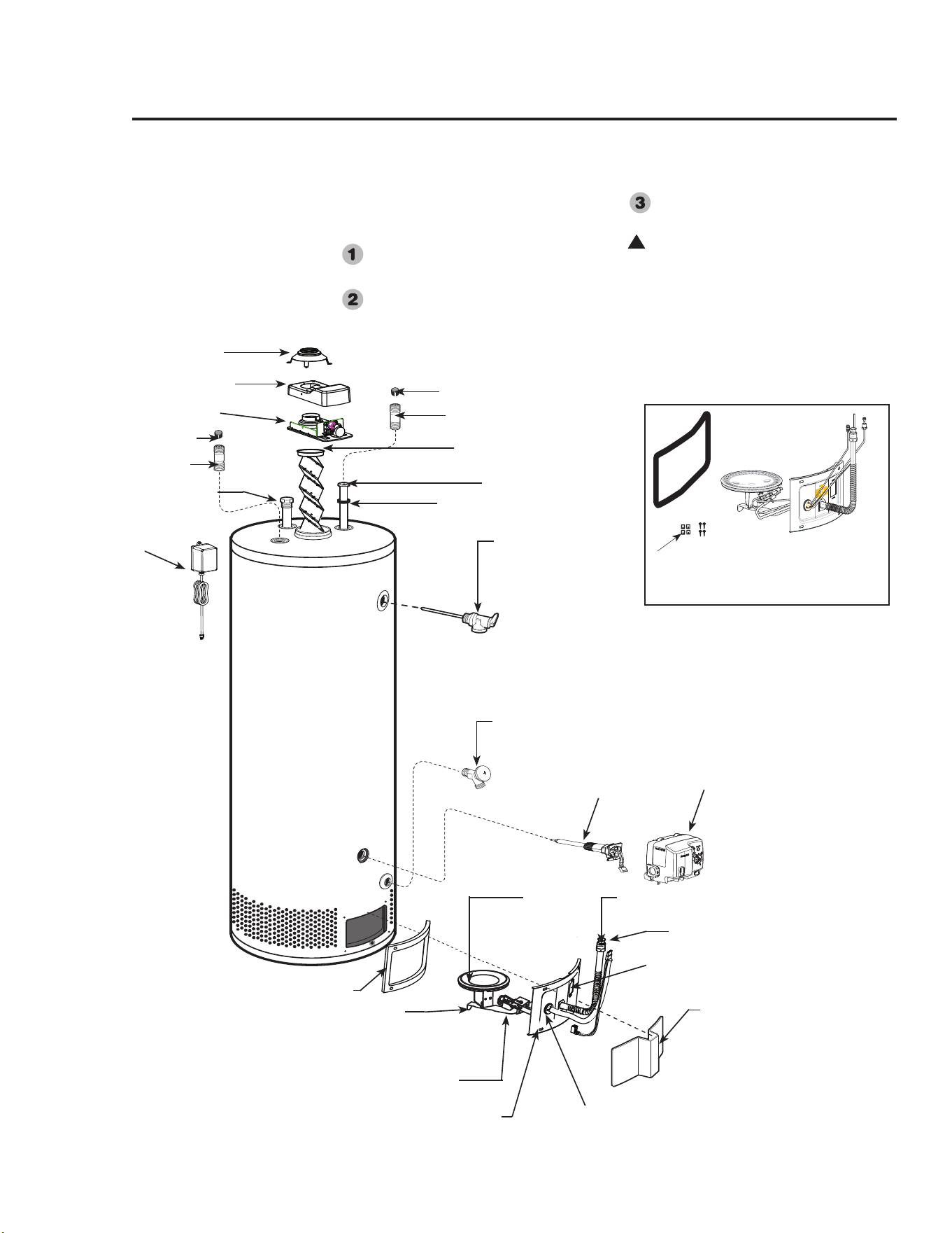
Replacement Parts
For38,40and50gallonmodelsusingnaturalorLPgas.
Instructions For Placing a Parts Order
Call1-800-268-6966.
Allpartsordersshouldinclude:
Themodelandserialnumberofthe
waterheaterfromtheratingplate.
Specifytypeofgas(naturalorLP)
asmarkedontheratingplate.
Partdescription(asnotedbelow)and
numberofpartsdesired.
CAUTION: For your safety, DO
NOT attempt repair of gas piping,
gas control (thermostat), burners,
vent connectors or other safety devices.
Refer repairs to qualified service
personnel.
!
Drafthood
Fluebaffleandhanger
Anoderod
**HeatTrap
**HeatTrap
**Nipple
**Nipple
Diptube
Diptubegasket
Drainvalve
Temperatureandpressure
reliefvalve
GasControl(Thermostat)
*Burnersupplytube
*Burner
JacketDoor
*BurnerAccessDoorGrommet
*SightGlass
*BurnerAccessDoor
*BurnerAccessDoorGasket
*PilotSupplyTube
*Burnerorifice
PilotAssembly
*BurnerAssemblyKit
Thekitprovidesextraspeedclips
andtamperresistantscrews.
**Notsuppliedwithallmodels.
GasControl(Thermostat)
ThermalWell
FlueDamperHousing
FlueDamper
Transformer

Notes:
27

IFYOUNEEDSERvICE
1. Shouldyouhaveanyquestionsaboutyournewwaterheater,orifitrequires
adjustment,repair,orroutinemaintenance,itissuggestedthatyoufirstcontact
yourinstaller,plumbingcontractororpreviouslyagreeduponserviceagency.In
theeventthefirmhasmoved,orisunavailable,refertothetelephonedirectory,
commerciallistingsorlocalutilityforqualifiedserviceassistance.
2. Shouldyourproblemnotbesolvedtoyourcompletesatisfaction,youshouldthen
contacttheManufacturer’sServiceDepartmentatthefollowingaddress:
RheemCanadaLtd.
125EdgewareRoad,Unit1
Brampton,ONL6YOP5
Phone:CustomerService1-800-432-8373
Warranty1-800-263-8342
Whencontactingthemanufacturer,thefollowinginformationwillberequested:
a. Modelandserialnumberofthewaterheaterasshownontheratingplateattached
tothejacketoftheheater.
b. Addresswherethewaterheaterislocatedandphysicallocation.
c. Nameandaddressofinstallerandanyserviceagencywhoperformedserviceon
thewaterheater.
d. Dateoforiginalinstallationanddatesanyserviceworkwasperformed.
e. Detailsoftheproblemsasyoucanbestdescribethem.
f. Listofpeople,withdates,whohavebeencontactedregardingyourproblem.
28