DESIGN 2 – For articulated hinge models
1. Pull the top decoration cover (3) upward and
remove it. Remove the cover caps (2) and then
remove the door by unscrewing the four screws
(1). Be careful to hold the door firmly after
2. removing the screws and place it on a padded
surface to avoid the risk of damage. Leave the
hinges open. (Figure 1)
3. Unscrew the four screws (4) to remove the top
and bottom articulated hinges. (Figure 2)
4. Pop out the cover caps on the left side of the
cabinet and use them to cover the screw holes
on the right-hand side.
5. Pull the top decoration cover (5) upward and remove it. Unscrew the two screws (6) and transfer the
retaining bracket (7) to the opposite side of the door. Refit the top decoration cover (5). (Figure 3)
6. Unscrew the screw (9) and transfer the bottom decoration cover (8) to the opposite side of the door.
(Figure 4)
7. Refit the articulated hinges to the opposite side of the door by using the four screws (3). (Repeat
step 2 in reverse.)
8. Refit the door to the opposite side. Then screw and tighten it after the door is leveled. (Repeat step 1
in reverse.)
DESIGN 3 – For panel ready models
1. Pull the top decoration cover (3) upward and
remove it. Remove the cover caps (2) and then
remove the door by unscrewing the four screws
(1). Be careful to hold the door firmly after
removing the screws and place it on a padded
surface to avoid the risk of damage. Leave the
hinges open. (Figure 1)
2. Unscrew the four screws (4) to remove the top
and bottom articulated hinges. (Figure 2)
3. Pop out the cover caps on the left side of the cabinet and use them to cover the screw holes on the
right-hand side.
4. Unscrew the two screws (5) and transfer the retaining bracket (6) to the opposite side of the door.
(Figure 3)
5. Refit the articulated hinges to the opposite side of the door by using the four screws (3). (Repeat
step 2 in reverse.)
6. Refit the door to the opposite side. Then screw and tighten it after the door is leveled. (Repeat step 1
in reverse.)
7. Refit the alternative top decoration cover included in the fittings on the top of door.
OVERLAY PANEL INSTALLATION INSTRUCTION
Door Panel Preparation
Depending on the model prepare the overlay panel to
the dimensions shown below. Then attach the handle
to the overlay panel by using the flat head screws and
drive the screws flush with the panel if needed.
NOTE:
H can be 28⅜" and 30". It depends on the actual product specification.
Weight of the overlay panel should not exceed 22 Lbs.
It is important to ensure that all drilled holes are drilled to the correct depth in order to
avoid splits in the wood when hardware is installed.
Drill the handle installation holes in the overlay panel according to the handle you are
planning to use. If reusing the handles came with the unit, drill two holes with holes
distance same as handle and diameter 5mm in the overlay panel.
use an extension cord with this appliance. However, if you must use an extension cord it is absolutely
necessary that it be a UL/CUL-listed, 3-wire grounding type appliance extension cord having a grounding
type plug and outlet and that the electrical rating of the cord be 115 volts and at least 10 amperes.
INSTALLING THE HANDLE
IMPORTANT: Do not overtighten the screws & do not use
power tools to install the handle.
DESIGN 1 –
Locate the handle (2) over the mounting stubs (1) of the
door and tighten the grub screws (3) with an Allen key to
secure the handle.
DESIGN 2 –
Remove the door gasket on the side you wish to install the
handle - you can see two designated holes for handle
installation.
Install the handle (3) tightly as shown above with two
screws (1) and flat washers (2) provided.
Replace the door gasket.
REVERSING THE DOOR HINGE
It is possible to reverse the door on this appliance, if
required.
To do so, follow the steps below:
Note: All parts removed must be saved to do the reinstallation of the door.
DESIGN 1 – For standard hinge models
1. Remove the bottom hinge (1) by unscrewing the
two lock screws (2). Be careful to hold the door
firmly after removing the screws. (Fig. 1)
2. Gently pull down to remove the door (3) from the
right top hinge and place it on a padded surface
to avoid the risk of damage. Then remove the
right top hinge (3). (Fig. 2 & 3)
3. Pop out the cover caps on the left side of cabinet
and use them to cover the screw holes on the
right hand side.
4. Screw the alternative left top hinge (4), included
in the fittings, on the left hand side of cabinet.
(Fig. 3)
5. Relocate the door to the designated position. Then screw the bottom hinge assembly on the left
designated position and tighten it after the door is leveled.
NOTE: Make sure that the socket and ON/OFF switch are easily accessible after the appliance has been
installed.
BUILT-UNDER INSTRUCTIONS
Make sure your installation does not block the front ventilation grill. If the unit is fully integrated to be
installed for fitting kitchen, make sure that the ventilation gaps in the plinth are at least 300 square
centimeters and remove the ventilation grilles, so that warm air can disperse unhindered. Otherwise the
appliance has to work harder, resulting in an increase in electricity consumption.
NOTE: When pushing the appliance into the niche, make sure that the mains cable does not get trapped.
CAUTION
To ensure the proper functioning of the appliance, air vents should never be blocked or covered.
ELECTRICAL CONNECTION
Check that the voltage marked on the product corresponds with your supply voltage
WARNING
Improper use of the grounded plug can result in the risk of electrical shock. If the power cord is damaged,
have it replaced by a qualified electrician or an authorized service center.
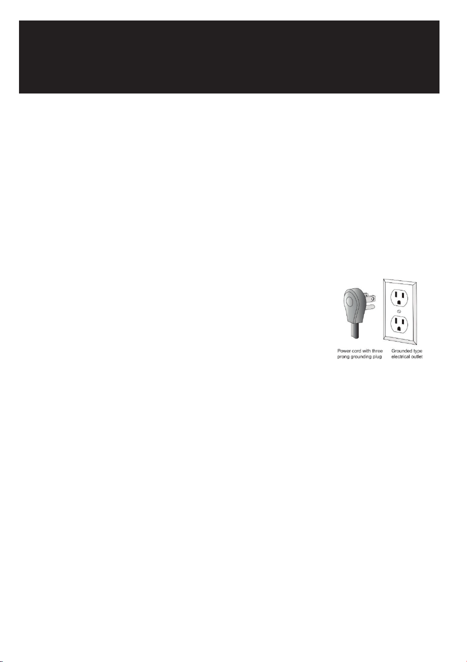
This appliance should be properly grounded for your safety. The power cord of this appliance is equipped
with a three-prong plug which mates with standard three-prong wall outlets to minimize the possibility of
electrical shock.
Do not under any circumstances cut or remove the third (ground) prong from the power cord supplied.
For personal safety, this appliance must be properly grounded.
This appliance requires a standard 115/120 Volt AC ~ 60Hz three-prong grounded electrical outlet. Have
the wall outlet and circuit checked by a qualified electrician to make sure the outlet is properly grounded.
When a standard 2-prong wall outlet is encountered, it is your responsibility and obligation to have it
replaced with a properly grounded 3-prong wall outlet.
To prevent accidental injury, the cord should be secured behind the appliance and not left exposed or
dangling.
The appliance should always be plugged into its own individual electrical outlet which has a voltage
rating that matches the rating label on the appliance. This provides the best performance and also
prevents overloading house wiring circuits that could cause a fire hazard from overheating. Never unplug
the appliance by pulling on the power cord. Always grip the plug firmly and pull straight out from the
receptacle. Repair or replace immediately all power cords that have become frayed or otherwise
damaged. Do not use a cord that shows cracks or abrasion damage along its length or at either end.
When moving the appliance, be careful not to damage the power cord.
EXTENSION CORD
Because of potential safety hazards under certain conditions, it is strongly recommended that you do not
BEFORE USING YOUR APPLIANCE
- Remove all exterior and interior packing. Clean the interior surface with lukewarm water using a soft
cloth. The unit may have residual odors at first, they will disappear as the unit cools.
- IMPORTANT: Before connecting the icemachine to the power source, let it stand upright for
approximately 24 hours. This will reduce the possibility of a malfunction in the cooling system
caused by handling during transportation.
- The door on this appliance can be opened either the left or the right side. The unit is delivered with
the door opening on the left side. Should you wish to open the door from the right, follow the
instructions "Reversing the door hinge".
- Install the handle on the door.
- Sanitize the ice machine. All ice machines are factory-operated and adjusted before shipment.
Normally, new installations do not require any adjustment.
INSTALLATION OF YOUR APPLIANCE
WARNING
This appliance must be installed in accordance with all local codes and ordinances.
• The appliances are designed to be built-in or recessed or free-standing installation.
• This ice machine should be properly installed by qualified personnel.
• WARNING: Flammable Refrigerant Used. Appliance should be installed in accordance with the
Safety Standard for Refrigeration Systems, ANSI/ASHRAE 15.
• Place your ice machine on a floor that is even and strong enough to support it when it is fully loaded.
It is very important for the ice machine to be level in order to work properly. To level your unit, adjust
the front adjustable legs at the bottom of the unit.
• For freestanding installation, 5 inches (127mm) of space between the back and sides of the unit are
suggested, which allows the proper air circulation to cool the compressor and condenser for energy
saving. Even for built-in installation, it is a must to keep ¾" (5mm) space on each side and at the top
to ensure proper service access and efficient ventilation. Take care that the air vent at the front of
the appliance must never be covered or blocked in any way.
• Installation of the ice maker requires a cold water supply inlet of ¼-in. (6.35mm) soft copper tubing
with a shut-off valve.
• Locate the unit away from direct sunlight and sources of heat (stove, heater, radiator, etc.). Direct
sunlight may affect the acrylic coating and heat sources may increase electrical consumption.
Extreme cold ambient temperatures may also cause the unit not to perform properly.
• Avoid locating the unit in damp areas.
• Plug the unit into an exclusive, easily accessible and properly grounded wall outlet. Do not under any
circumstances cut or remove the third (ground) prong from the power cord. Any questions concern-
ing power and/or earthing should be directed towards a qualified electrician or an authorized
products service centre.
• The appliance must be installed to all electrical, plumbing, water and drain connections in
accordance with state and local codes.
• The equipment must be installed with adequate backflow protection to comply with applicable
federal, state and local codes.
• It is strongly recommended that a water filter be used. A filter, if it is of the proper type, can remove
taste and odors as well as particles. Some water is very hard, and softened water may result in
white, mushy cubes that stick together. Deionized water is not recommended.
Door Panel Installation
Attach the wood overlay panel (1) on the door (2) by using the four wood screws ST4x15 Type AB Philips
(3).
WATER SUPPLY AND DRAIN REQUIREMENTS
Prepare water supply line and drain before installation of your ice machine. Installation requires a 1/4" ID
copper cold water line and compression fitting (not supplied).
The ice machine IM50 is supplied with an automatic drain pump system. The ice machine IM30 is
supplied with a drain hose for gravity draining. Both drain methods require routing to an open site drain.
Do not connect directly to drain line as bacteria from drain line may contaminate the ice machine.
Make certain the hoses are not pinched or kinked or damaged during installation.
Check for leaks after connection.
WATER INLET LINES
CAUTION
Copper tubing is recommended for the water supply line. Water supply tubing made of 1/4" plastic is not
recommended since it greatly increases the potential for water leaks. Manufacturer will not be responsible
for any damage if plastic tubing is used for the supply line.
Follow these guidelines to install water inlet lines:
▪ Do not connect the ice machine to a hot water supply. Be sure all hot water restrictors installed for
other equipment are working. (Check valves on sink faucets, dishwashers, etc.)
▪ If water pressure exceeds the maximum recommended pressure (80 psi - 55 bar), obtain a water
pressure regulator.
▪ Install a water shut-off valve for the ice making water lines.
▪ Insulate the water inlet line to prevent condensation.
▪ Install tubing only in areas where temperatures will remain above freezing.
▪ Leave a coil of copper tubing to allow the ice maker to be pulled out of the cabinet or away from the
wall for service.
DRAIN CONNECTIONS (FACTORY SUPPLIED)
Follow these guidelines when installing drain lines to prevent drain water from flowing back into the ice
machine and storage bin:
▪ Drain lines must have a 1.5 inch drop per 5 feet of run (2.5 cm per meter), and must not create traps.
▪ The floor drain must be large enough to accommodate drainage from all drains.
▪ Drain pump discharge line must terminate at an open site drain.
▪ The maximum length of drain hose is 5 feet (1.5
m).
▪ The maximum rise of drain hose is 2.6 feet (0.8
m).
▪ Pour 3000ml of water into the ice storage bin to
check for leaks in the drainage system.
WATER SUPPLY AND DRAIN LINE
SIZING/CONNECTIONS
CAUTION
Plumbing must conform to state and local codes.
NOTE: If air temperature is less than 60°F (15.5°C), water
temperature must be equal to or greater than 50°F (10°C).
INSTALLATION PROCEDURE
1. Prepare the site by following the instructions under Electrical Connection and Water Supply and
Drain Requirements.
2. Remove ice machine from carton.
3. Inspect for damage.
4. Remove literature packet and drain hose from inside the ice machine.
5. Adjust leg levelers.
6. Reverse door if desired. See Reversing the Door Hinge.
7. Install drain hose to drain on back of ice machine and route to open site drain.
8. Use compression fitting to connect the Water Inlet on back of ice machine to the prepared 1/4" ID
cold water line.
9. Open the shut-off valve on the water line.
10. Connect electrical plug to grounded (three-prong), polarized outlet.
11. Place ice machine back in position and check leveling again. Make any necessary adjustments.
12. Prepare sanitizer solution and sanitize the ice machine according to Cleaning/Sanitizing the Ice
Making System.
13. At initial start-up, ice machine will need approximately 45 minutes to freeze.
INSTALLATION CHECK LIST
▪ Is the Ice Machine level?!
▪ Has all of the packing been removed?
▪ Have all of the electrical and water connections been made?
▪ Has the supply voltage been tested and checked against the rating on the nameplate?
▪ Is there proper clearance around the ice machine for air circulation?
▪ Has the ice machine been installed where ambient temperatures will remain in the range of 41° -
100°F (5° - 38°C)?
▪ Has the ice machine been installed where the incoming water temperature will remain in the range
of 41° - 90°F (5° - 32°C)?
▪ Has the water supply pressure been checked to ensure a minimum of 20 psig with a static pressure
not to exceed 80 psig?
▪ Is the ice machine drain line routed to an open site drain?
▪ Are all electrical leads free from contact with refrigeration lines and moving equipment?
▪ Has the ice machine and bin been sanitized?
▪ Is the ice machine plugged into a properly grounded, polarized receptacle?
▪ Have the water and drain connections been examined for leaks?
USER MANUAL
Before using, please read the operating instructions carefully to
ensure proper application and achieve satisfactory results.
For any service related
issues, please contact us:
718-576-6342
support@koolmore.com
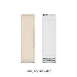
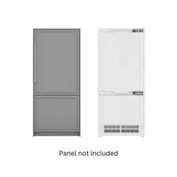
PANEL READY
KOOLMORE RESERVE
Residential Panel Ready Ice Maker
57 lbs/24hr 15"x34"
Model: KM-BIM57-PR

DESIGN 2 – For articulated hinge models
1. Pull the top decoration cover (3) upward and
remove it. Remove the cover caps (2) and then
remove the door by unscrewing the four screws
(1). Be careful to hold the door firmly after
2. removing the screws and place it on a padded
surface to avoid the risk of damage. Leave the
hinges open. (Figure 1)
3. Unscrew the four screws (4) to remove the top
and bottom articulated hinges. (Figure 2)
4. Pop out the cover caps on the left side of the
cabinet and use them to cover the screw holes
on the right-hand side.
5. Pull the top decoration cover (5) upward and remove it. Unscrew the two screws (6) and transfer the
retaining bracket (7) to the opposite side of the door. Refit the top decoration cover (5). (Figure 3)
6. Unscrew the screw (9) and transfer the bottom decoration cover (8) to the opposite side of the door.
(Figure 4)
7. Refit the articulated hinges to the opposite side of the door by using the four screws (3). (Repeat
step 2 in reverse.)
8. Refit the door to the opposite side. Then screw and tighten it after the door is leveled. (Repeat step 1
in reverse.)
DESIGN 3 – For panel ready models
1. Pull the top decoration cover (3) upward and
remove it. Remove the cover caps (2) and then
remove the door by unscrewing the four screws
(1). Be careful to hold the door firmly after
removing the screws and place it on a padded
surface to avoid the risk of damage. Leave the
hinges open. (Figure 1)
2. Unscrew the four screws (4) to remove the top
and bottom articulated hinges. (Figure 2)
3. Pop out the cover caps on the left side of the cabinet and use them to cover the screw holes on the
right-hand side.
4. Unscrew the two screws (5) and transfer the retaining bracket (6) to the opposite side of the door.
(Figure 3)
5. Refit the articulated hinges to the opposite side of the door by using the four screws (3). (Repeat
step 2 in reverse.)
6. Refit the door to the opposite side. Then screw and tighten it after the door is leveled. (Repeat step 1
in reverse.)
7. Refit the alternative top decoration cover included in the fittings on the top of door.
OVERLAY PANEL INSTALLATION INSTRUCTION
Door Panel Preparation
Depending on the model prepare the overlay panel to
the dimensions shown below. Then attach the handle
to the overlay panel by using the flat head screws and
drive the screws flush with the panel if needed.
NOTE:
H can be 28⅜" and 30". It depends on the actual product specification.
Weight of the overlay panel should not exceed 22 Lbs.
It is important to ensure that all drilled holes are drilled to the correct depth in order to
avoid splits in the wood when hardware is installed.
Drill the handle installation holes in the overlay panel according to the handle you are
planning to use. If reusing the handles came with the unit, drill two holes with holes
distance same as handle and diameter 5mm in the overlay panel.
use an extension cord with this appliance. However, if you must use an extension cord it is absolutely
necessary that it be a UL/CUL-listed, 3-wire grounding type appliance extension cord having a grounding
type plug and outlet and that the electrical rating of the cord be 115 volts and at least 10 amperes.
INSTALLING THE HANDLE
IMPORTANT: Do not overtighten the screws & do not use
power tools to install the handle.
DESIGN 1 –
Locate the handle (2) over the mounting stubs (1) of the
door and tighten the grub screws (3) with an Allen key to
secure the handle.
DESIGN 2 –
Remove the door gasket on the side you wish to install the
handle - you can see two designated holes for handle
installation.
Install the handle (3) tightly as shown above with two
screws (1) and flat washers (2) provided.
Replace the door gasket.
REVERSING THE DOOR HINGE
It is possible to reverse the door on this appliance, if
required.
To do so, follow the steps below:
Note: All parts removed must be saved to do the reinstallation of the door.
DESIGN 1 – For standard hinge models
1. Remove the bottom hinge (1) by unscrewing the
two lock screws (2). Be careful to hold the door
firmly after removing the screws. (Fig. 1)
2. Gently pull down to remove the door (3) from the
right top hinge and place it on a padded surface
to avoid the risk of damage. Then remove the
right top hinge (3). (Fig. 2 & 3)
3. Pop out the cover caps on the left side of cabinet
and use them to cover the screw holes on the
right hand side.
4. Screw the alternative left top hinge (4), included
in the fittings, on the left hand side of cabinet.
(Fig. 3)
5. Relocate the door to the designated position. Then screw the bottom hinge assembly on the left
designated position and tighten it after the door is leveled.
NOTE: Make sure that the socket and ON/OFF switch are easily accessible after the appliance has been
installed.
BUILT-UNDER INSTRUCTIONS
Make sure your installation does not block the front ventilation grill. If the unit is fully integrated to be
installed for fitting kitchen, make sure that the ventilation gaps in the plinth are at least 300 square
centimeters and remove the ventilation grilles, so that warm air can disperse unhindered. Otherwise the
appliance has to work harder, resulting in an increase in electricity consumption.
NOTE: When pushing the appliance into the niche, make sure that the mains cable does not get trapped.
CAUTION
To ensure the proper functioning of the appliance, air vents should never be blocked or covered.
ELECTRICAL CONNECTION
Check that the voltage marked on the product corresponds with your supply voltage
WARNING
Improper use of the grounded plug can result in the risk of electrical shock. If the power cord is damaged,
have it replaced by a qualified electrician or an authorized service center.
This appliance should be properly grounded for your safety. The power cord of this appliance is equipped
with a three-prong plug which mates with standard three-prong wall outlets to minimize the possibility of
electrical shock.
Do not under any circumstances cut or remove the third (ground) prong from the power cord supplied.
For personal safety, this appliance must be properly grounded.
This appliance requires a standard 115/120 Volt AC ~ 60Hz three-prong grounded electrical outlet. Have
the wall outlet and circuit checked by a qualified electrician to make sure the outlet is properly grounded.
When a standard 2-prong wall outlet is encountered, it is your responsibility and obligation to have it
replaced with a properly grounded 3-prong wall outlet.
To prevent accidental injury, the cord should be secured behind the appliance and not left exposed or
dangling.
The appliance should always be plugged into its own individual electrical outlet which has a voltage
rating that matches the rating label on the appliance. This provides the best performance and also
prevents overloading house wiring circuits that could cause a fire hazard from overheating. Never unplug
the appliance by pulling on the power cord. Always grip the plug firmly and pull straight out from the
receptacle. Repair or replace immediately all power cords that have become frayed or otherwise
damaged. Do not use a cord that shows cracks or abrasion damage along its length or at either end.
When moving the appliance, be careful not to damage the power cord.
EXTENSION CORD
Because of potential safety hazards under certain conditions, it is strongly recommended that you do not
BEFORE USING YOUR APPLIANCE
- Remove all exterior and interior packing. Clean the interior surface with lukewarm water using a soft
cloth. The unit may have residual odors at first, they will disappear as the unit cools.
- IMPORTANT: Before connecting the icemachine to the power source, let it stand upright for
approximately 24 hours. This will reduce the possibility of a malfunction in the cooling system
caused by handling during transportation.
- The door on this appliance can be opened either the left or the right side. The unit is delivered with
the door opening on the left side. Should you wish to open the door from the right, follow the
instructions "Reversing the door hinge".
- Install the handle on the door.
- Sanitize the ice machine. All ice machines are factory-operated and adjusted before shipment.
Normally, new installations do not require any adjustment.
INSTALLATION OF YOUR APPLIANCE
WARNING
This appliance must be installed in accordance with all local codes and ordinances.
• The appliances are designed to be built-in or recessed or free-standing installation.
• This ice machine should be properly installed by qualified personnel.
• WARNING: Flammable Refrigerant Used. Appliance should be installed in accordance with the
Safety Standard for Refrigeration Systems, ANSI/ASHRAE 15.
• Place your ice machine on a floor that is even and strong enough to support it when it is fully loaded.
It is very important for the ice machine to be level in order to work properly. To level your unit, adjust
the front adjustable legs at the bottom of the unit.
• For freestanding installation, 5 inches (127mm) of space between the back and sides of the unit are
suggested, which allows the proper air circulation to cool the compressor and condenser for energy
saving. Even for built-in installation, it is a must to keep ¾" (5mm) space on each side and at the top
to ensure proper service access and efficient ventilation. Take care that the air vent at the front of
the appliance must never be covered or blocked in any way.
• Installation of the ice maker requires a cold water supply inlet of ¼-in. (6.35mm) soft copper tubing
with a shut-off valve.
• Locate the unit away from direct sunlight and sources of heat (stove, heater, radiator, etc.). Direct
sunlight may affect the acrylic coating and heat sources may increase electrical consumption.
Extreme cold ambient temperatures may also cause the unit not to perform properly.
• Avoid locating the unit in damp areas.
• Plug the unit into an exclusive, easily accessible and properly grounded wall outlet. Do not under any
circumstances cut or remove the third (ground) prong from the power cord. Any questions concern-
ing power and/or earthing should be directed towards a qualified electrician or an authorized
products service centre.
• The appliance must be installed to all electrical, plumbing, water and drain connections in
accordance with state and local codes.
• The equipment must be installed with adequate backflow protection to comply with applicable
federal, state and local codes.
• It is strongly recommended that a water filter be used. A filter, if it is of the proper type, can remove
taste and odors as well as particles. Some water is very hard, and softened water may result in
white, mushy cubes that stick together. Deionized water is not recommended.
Door Panel Installation
Attach the wood overlay panel (1) on the door (2) by using the four wood screws ST4x15 Type AB Philips
(3).
WATER SUPPLY AND DRAIN REQUIREMENTS
Prepare water supply line and drain before installation of your ice machine. Installation requires a 1/4" ID
copper cold water line and compression fitting (not supplied).
The ice machine IM50 is supplied with an automatic drain pump system. The ice machine IM30 is
supplied with a drain hose for gravity draining. Both drain methods require routing to an open site drain.
Do not connect directly to drain line as bacteria from drain line may contaminate the ice machine.
Make certain the hoses are not pinched or kinked or damaged during installation.
Check for leaks after connection.
WATER INLET LINES
CAUTION
Copper tubing is recommended for the water supply line. Water supply tubing made of 1/4" plastic is not
recommended since it greatly increases the potential for water leaks. Manufacturer will not be responsible
for any damage if plastic tubing is used for the supply line.
Follow these guidelines to install water inlet lines:
▪ Do not connect the ice machine to a hot water supply. Be sure all hot water restrictors installed for
other equipment are working. (Check valves on sink faucets, dishwashers, etc.)
▪ If water pressure exceeds the maximum recommended pressure (80 psi - 55 bar), obtain a water
pressure regulator.
▪ Install a water shut-off valve for the ice making water lines.
▪ Insulate the water inlet line to prevent condensation.
▪ Install tubing only in areas where temperatures will remain above freezing.
▪ Leave a coil of copper tubing to allow the ice maker to be pulled out of the cabinet or away from the
wall for service.
DRAIN CONNECTIONS (FACTORY SUPPLIED)
Follow these guidelines when installing drain lines to prevent drain water from flowing back into the ice
machine and storage bin:
▪ Drain lines must have a 1.5 inch drop per 5 feet of run (2.5 cm per meter), and must not create traps.
▪ The floor drain must be large enough to accommodate drainage from all drains.
▪ Drain pump discharge line must terminate at an open site drain.
▪ The maximum length of drain hose is 5 feet (1.5
m).
▪ The maximum rise of drain hose is 2.6 feet (0.8
m).
▪ Pour 3000ml of water into the ice storage bin to
check for leaks in the drainage system.
WATER SUPPLY AND DRAIN LINE
SIZING/CONNECTIONS
CAUTION
Plumbing must conform to state and local codes.
NOTE: If air temperature is less than 60°F (15.5°C), water
temperature must be equal to or greater than 50°F (10°C).
INSTALLATION PROCEDURE
1. Prepare the site by following the instructions under Electrical Connection and Water Supply and
Drain Requirements.
2. Remove ice machine from carton.
3. Inspect for damage.
4. Remove literature packet and drain hose from inside the ice machine.
5. Adjust leg levelers.
6. Reverse door if desired. See Reversing the Door Hinge.
7. Install drain hose to drain on back of ice machine and route to open site drain.
8. Use compression fitting to connect the Water Inlet on back of ice machine to the prepared 1/4" ID
cold water line.
9. Open the shut-off valve on the water line.
10. Connect electrical plug to grounded (three-prong), polarized outlet.
11. Place ice machine back in position and check leveling again. Make any necessary adjustments.
12. Prepare sanitizer solution and sanitize the ice machine according to Cleaning/Sanitizing the Ice
Making System.
13. At initial start-up, ice machine will need approximately 45 minutes to freeze.
INSTALLATION CHECK LIST
▪ Is the Ice Machine level?!
▪ Has all of the packing been removed?
▪ Have all of the electrical and water connections been made?
▪ Has the supply voltage been tested and checked against the rating on the nameplate?
▪ Is there proper clearance around the ice machine for air circulation?
▪ Has the ice machine been installed where ambient temperatures will remain in the range of 41° -
100°F (5° - 38°C)?
▪ Has the ice machine been installed where the incoming water temperature will remain in the range
of 41° - 90°F (5° - 32°C)?
▪ Has the water supply pressure been checked to ensure a minimum of 20 psig with a static pressure
not to exceed 80 psig?
▪ Is the ice machine drain line routed to an open site drain?
▪ Are all electrical leads free from contact with refrigeration lines and moving equipment?
▪ Has the ice machine and bin been sanitized?
▪ Is the ice machine plugged into a properly grounded, polarized receptacle?
▪ Have the water and drain connections been examined for leaks?
Stay informed with the latest information for your
KoolMore Reserve Appliance.
If you need any assistance or have questions, our
customer support team is here to help.

DESIGN 2 – For articulated hinge models
1. Pull the top decoration cover (3) upward and
remove it. Remove the cover caps (2) and then
remove the door by unscrewing the four screws
(1). Be careful to hold the door firmly after
2. removing the screws and place it on a padded
surface to avoid the risk of damage. Leave the
hinges open. (Figure 1)
3. Unscrew the four screws (4) to remove the top
and bottom articulated hinges. (Figure 2)
4. Pop out the cover caps on the left side of the
cabinet and use them to cover the screw holes
on the right-hand side.
5. Pull the top decoration cover (5) upward and remove it. Unscrew the two screws (6) and transfer the
retaining bracket (7) to the opposite side of the door. Refit the top decoration cover (5). (Figure 3)
6. Unscrew the screw (9) and transfer the bottom decoration cover (8) to the opposite side of the door.
(Figure 4)
7. Refit the articulated hinges to the opposite side of the door by using the four screws (3). (Repeat
step 2 in reverse.)
8. Refit the door to the opposite side. Then screw and tighten it after the door is leveled. (Repeat step 1
in reverse.)
DESIGN 3 – For panel ready models
1. Pull the top decoration cover (3) upward and
remove it. Remove the cover caps (2) and then
remove the door by unscrewing the four screws
(1). Be careful to hold the door firmly after
removing the screws and place it on a padded
surface to avoid the risk of damage. Leave the
hinges open. (Figure 1)
2. Unscrew the four screws (4) to remove the top
and bottom articulated hinges. (Figure 2)
3. Pop out the cover caps on the left side of the cabinet and use them to cover the screw holes on the
right-hand side.
4. Unscrew the two screws (5) and transfer the retaining bracket (6) to the opposite side of the door.
(Figure 3)
5. Refit the articulated hinges to the opposite side of the door by using the four screws (3). (Repeat
step 2 in reverse.)
6. Refit the door to the opposite side. Then screw and tighten it after the door is leveled. (Repeat step 1
in reverse.)
7. Refit the alternative top decoration cover included in the fittings on the top of door.
OVERLAY PANEL INSTALLATION INSTRUCTION
Door Panel Preparation
Depending on the model prepare the overlay panel to
the dimensions shown below. Then attach the handle
to the overlay panel by using the flat head screws and
drive the screws flush with the panel if needed.
NOTE:
H can be 28⅜" and 30". It depends on the actual product specification.
Weight of the overlay panel should not exceed 22 Lbs.
It is important to ensure that all drilled holes are drilled to the correct depth in order to
avoid splits in the wood when hardware is installed.
Drill the handle installation holes in the overlay panel according to the handle you are
planning to use. If reusing the handles came with the unit, drill two holes with holes
distance same as handle and diameter 5mm in the overlay panel.
use an extension cord with this appliance. However, if you must use an extension cord it is absolutely
necessary that it be a UL/CUL-listed, 3-wire grounding type appliance extension cord having a grounding
type plug and outlet and that the electrical rating of the cord be 115 volts and at least 10 amperes.
INSTALLING THE HANDLE
IMPORTANT: Do not overtighten the screws & do not use
power tools to install the handle.
DESIGN 1 –
Locate the handle (2) over the mounting stubs (1) of the
door and tighten the grub screws (3) with an Allen key to
secure the handle.
DESIGN 2 –
Remove the door gasket on the side you wish to install the
handle - you can see two designated holes for handle
installation.
Install the handle (3) tightly as shown above with two
screws (1) and flat washers (2) provided.
Replace the door gasket.
REVERSING THE DOOR HINGE
It is possible to reverse the door on this appliance, if
required.
To do so, follow the steps below:
Note: All parts removed must be saved to do the reinstallation of the door.
DESIGN 1 – For standard hinge models
1. Remove the bottom hinge (1) by unscrewing the
two lock screws (2). Be careful to hold the door
firmly after removing the screws. (Fig. 1)
2. Gently pull down to remove the door (3) from the
right top hinge and place it on a padded surface
to avoid the risk of damage. Then remove the
right top hinge (3). (Fig. 2 & 3)
3. Pop out the cover caps on the left side of cabinet
and use them to cover the screw holes on the
right hand side.
4. Screw the alternative left top hinge (4), included
in the fittings, on the left hand side of cabinet.
(Fig. 3)
5. Relocate the door to the designated position. Then screw the bottom hinge assembly on the left
designated position and tighten it after the door is leveled.
NOTE: Make sure that the socket and ON/OFF switch are easily accessible after the appliance has been
installed.
BUILT-UNDER INSTRUCTIONS
Make sure your installation does not block the front ventilation grill. If the unit is fully integrated to be
installed for fitting kitchen, make sure that the ventilation gaps in the plinth are at least 300 square
centimeters and remove the ventilation grilles, so that warm air can disperse unhindered. Otherwise the
appliance has to work harder, resulting in an increase in electricity consumption.
NOTE: When pushing the appliance into the niche, make sure that the mains cable does not get trapped.
CAUTION
To ensure the proper functioning of the appliance, air vents should never be blocked or covered.
ELECTRICAL CONNECTION
Check that the voltage marked on the product corresponds with your supply voltage
WARNING
Improper use of the grounded plug can result in the risk of electrical shock. If the power cord is damaged,
have it replaced by a qualified electrician or an authorized service center.
This appliance should be properly grounded for your safety. The power cord of this appliance is equipped
with a three-prong plug which mates with standard three-prong wall outlets to minimize the possibility of
electrical shock.
Do not under any circumstances cut or remove the third (ground) prong from the power cord supplied.
For personal safety, this appliance must be properly grounded.
This appliance requires a standard 115/120 Volt AC ~ 60Hz three-prong grounded electrical outlet. Have
the wall outlet and circuit checked by a qualified electrician to make sure the outlet is properly grounded.
When a standard 2-prong wall outlet is encountered, it is your responsibility and obligation to have it
replaced with a properly grounded 3-prong wall outlet.
To prevent accidental injury, the cord should be secured behind the appliance and not left exposed or
dangling.
The appliance should always be plugged into its own individual electrical outlet which has a voltage
rating that matches the rating label on the appliance. This provides the best performance and also
prevents overloading house wiring circuits that could cause a fire hazard from overheating. Never unplug
the appliance by pulling on the power cord. Always grip the plug firmly and pull straight out from the
receptacle. Repair or replace immediately all power cords that have become frayed or otherwise
damaged. Do not use a cord that shows cracks or abrasion damage along its length or at either end.
When moving the appliance, be careful not to damage the power cord.
EXTENSION CORD
Because of potential safety hazards under certain conditions, it is strongly recommended that you do not
INSTALLER: Leave these instructions with the appliance.
CUSTOMER: Read this manual carefully before using and starting up, and
save it for future use. If you pass on the product to another person, hand
over this instruction manual along with it. Retain your sales receipt or
cancelled check. Proof of original purchase date is required for warranty
service.
Have the complete model and serial number identification of your
appliance ready. These numbers are found on the rating label located
inside the door. Record these numbers below for easy access.
Model number __________________
Serial number __________________
Date of purchase ________________
Since we continually improve the quality and performance of our products,
we may make changes to the appliance without updating this manual.
SAFETY INSTRUCTIONS
Your safety and the safety of others are very important. We have provided many important safety
messages in this manual and on your appliance. Always read and obey all safety messages. The
Important Safety Instructions and warnings in this manual are not meant to cover all possible
problems and situations that can occur. Use common sense and caution when installing, maintaining
or operating this or any other appliance.
Always contact the Customer Service Team about problems or situations that you do not understand.
All safety messages will follow the the words "DANGER", "WARNING" or "CAUTION".
DANGER
DANGER – immediate hazards that WILL result in severe personal injury
or death.
WARNING
WARNING – potential hazards that COULD result in severe personal injury
or death.
CAUTION
CAUTION – hazards or unsafe practices that COULD result in minor
personal injury or property damage.
BEFORE USING YOUR APPLIANCE
- Remove all exterior and interior packing. Clean the interior surface with lukewarm water using a soft
cloth. The unit may have residual odors at first, they will disappear as the unit cools.
- IMPORTANT: Before connecting the icemachine to the power source, let it stand upright for
approximately 24 hours. This will reduce the possibility of a malfunction in the cooling system
caused by handling during transportation.
- The door on this appliance can be opened either the left or the right side. The unit is delivered with
the door opening on the left side. Should you wish to open the door from the right, follow the
instructions "Reversing the door hinge".
- Install the handle on the door.
- Sanitize the ice machine. All ice machines are factory-operated and adjusted before shipment.
Normally, new installations do not require any adjustment.
INSTALLATION OF YOUR APPLIANCE
WARNING
This appliance must be installed in accordance with all local codes and ordinances.
• The appliances are designed to be built-in or recessed or free-standing installation.
• This ice machine should be properly installed by qualified personnel.
• WARNING: Flammable Refrigerant Used. Appliance should be installed in accordance with the
Safety Standard for Refrigeration Systems, ANSI/ASHRAE 15.
• Place your ice machine on a floor that is even and strong enough to support it when it is fully loaded.
It is very important for the ice machine to be level in order to work properly. To level your unit, adjust
the front adjustable legs at the bottom of the unit.
• For freestanding installation, 5 inches (127mm) of space between the back and sides of the unit are
suggested, which allows the proper air circulation to cool the compressor and condenser for energy
saving. Even for built-in installation, it is a must to keep ¾" (5mm) space on each side and at the top
to ensure proper service access and efficient ventilation. Take care that the air vent at the front of
the appliance must never be covered or blocked in any way.
• Installation of the ice maker requires a cold water supply inlet of ¼-in. (6.35mm) soft copper tubing
with a shut-off valve.
• Locate the unit away from direct sunlight and sources of heat (stove, heater, radiator, etc.). Direct
sunlight may affect the acrylic coating and heat sources may increase electrical consumption.
Extreme cold ambient temperatures may also cause the unit not to perform properly.
• Avoid locating the unit in damp areas.
• Plug the unit into an exclusive, easily accessible and properly grounded wall outlet. Do not under any
circumstances cut or remove the third (ground) prong from the power cord. Any questions concern-
ing power and/or earthing should be directed towards a qualified electrician or an authorized
products service centre.
• The appliance must be installed to all electrical, plumbing, water and drain connections in
accordance with state and local codes.
• The equipment must be installed with adequate backflow protection to comply with applicable
federal, state and local codes.
• It is strongly recommended that a water filter be used. A filter, if it is of the proper type, can remove
taste and odors as well as particles. Some water is very hard, and softened water may result in
white, mushy cubes that stick together. Deionized water is not recommended.
Door Panel Installation
Attach the wood overlay panel (1) on the door (2) by using the four wood screws ST4x15 Type AB Philips
(3).
WATER SUPPLY AND DRAIN REQUIREMENTS
Prepare water supply line and drain before installation of your ice machine. Installation requires a 1/4" ID
copper cold water line and compression fitting (not supplied).
The ice machine IM50 is supplied with an automatic drain pump system. The ice machine IM30 is
supplied with a drain hose for gravity draining. Both drain methods require routing to an open site drain.
Do not connect directly to drain line as bacteria from drain line may contaminate the ice machine.
Make certain the hoses are not pinched or kinked or damaged during installation.
Check for leaks after connection.
WATER INLET LINES
CAUTION
Copper tubing is recommended for the water supply line. Water supply tubing made of 1/4" plastic is not
recommended since it greatly increases the potential for water leaks. Manufacturer will not be responsible
for any damage if plastic tubing is used for the supply line.
Follow these guidelines to install water inlet lines:
▪ Do not connect the ice machine to a hot water supply. Be sure all hot water restrictors installed for
other equipment are working. (Check valves on sink faucets, dishwashers, etc.)
▪ If water pressure exceeds the maximum recommended pressure (80 psi - 55 bar), obtain a water
pressure regulator.
▪ Install a water shut-off valve for the ice making water lines.
▪ Insulate the water inlet line to prevent condensation.
▪ Install tubing only in areas where temperatures will remain above freezing.
▪ Leave a coil of copper tubing to allow the ice maker to be pulled out of the cabinet or away from the
wall for service.
DRAIN CONNECTIONS (FACTORY SUPPLIED)
Follow these guidelines when installing drain lines to prevent drain water from flowing back into the ice
machine and storage bin:
▪ Drain lines must have a 1.5 inch drop per 5 feet of run (2.5 cm per meter), and must not create traps.
▪ The floor drain must be large enough to accommodate drainage from all drains.
▪ Drain pump discharge line must terminate at an open site drain.
▪ The maximum length of drain hose is 5 feet (1.5
m).
▪ The maximum rise of drain hose is 2.6 feet (0.8
m).
▪ Pour 3000ml of water into the ice storage bin to
check for leaks in the drainage system.
WATER SUPPLY AND DRAIN LINE
SIZING/CONNECTIONS
CAUTION
Plumbing must conform to state and local codes.
NOTE: If air temperature is less than 60°F (15.5°C), water
temperature must be equal to or greater than 50°F (10°C).
INSTALLATION PROCEDURE
1. Prepare the site by following the instructions under Electrical Connection and Water Supply and
Drain Requirements.
2. Remove ice machine from carton.
3. Inspect for damage.
4. Remove literature packet and drain hose from inside the ice machine.
5. Adjust leg levelers.
6. Reverse door if desired. See Reversing the Door Hinge.
7. Install drain hose to drain on back of ice machine and route to open site drain.
8. Use compression fitting to connect the Water Inlet on back of ice machine to the prepared 1/4" ID
cold water line.
9. Open the shut-off valve on the water line.
10. Connect electrical plug to grounded (three-prong), polarized outlet.
11. Place ice machine back in position and check leveling again. Make any necessary adjustments.
12. Prepare sanitizer solution and sanitize the ice machine according to Cleaning/Sanitizing the Ice
Making System.
13. At initial start-up, ice machine will need approximately 45 minutes to freeze.
INSTALLATION CHECK LIST
▪ Is the Ice Machine level?!
▪ Has all of the packing been removed?
▪ Have all of the electrical and water connections been made?
▪ Has the supply voltage been tested and checked against the rating on the nameplate?
▪ Is there proper clearance around the ice machine for air circulation?
▪ Has the ice machine been installed where ambient temperatures will remain in the range of 41° -
100°F (5° - 38°C)?
▪ Has the ice machine been installed where the incoming water temperature will remain in the range
of 41° - 90°F (5° - 32°C)?
▪ Has the water supply pressure been checked to ensure a minimum of 20 psig with a static pressure
not to exceed 80 psig?
▪ Is the ice machine drain line routed to an open site drain?
▪ Are all electrical leads free from contact with refrigeration lines and moving equipment?
▪ Has the ice machine and bin been sanitized?
▪ Is the ice machine plugged into a properly grounded, polarized receptacle?
▪ Have the water and drain connections been examined for leaks?
2
DESIGN 2 – For articulated hinge models
1. Pull the top decoration cover (3) upward and
remove it. Remove the cover caps (2) and then
remove the door by unscrewing the four screws
(1). Be careful to hold the door firmly after
2. removing the screws and place it on a padded
surface to avoid the risk of damage. Leave the
hinges open. (Figure 1)
3. Unscrew the four screws (4) to remove the top
and bottom articulated hinges. (Figure 2)
4. Pop out the cover caps on the left side of the
cabinet and use them to cover the screw holes
on the right-hand side.
5. Pull the top decoration cover (5) upward and remove it. Unscrew the two screws (6) and transfer the
retaining bracket (7) to the opposite side of the door. Refit the top decoration cover (5). (Figure 3)
6. Unscrew the screw (9) and transfer the bottom decoration cover (8) to the opposite side of the door.
(Figure 4)
7. Refit the articulated hinges to the opposite side of the door by using the four screws (3). (Repeat
step 2 in reverse.)
8. Refit the door to the opposite side. Then screw and tighten it after the door is leveled. (Repeat step 1
in reverse.)
DESIGN 3 – For panel ready models
1. Pull the top decoration cover (3) upward and
remove it. Remove the cover caps (2) and then
remove the door by unscrewing the four screws
(1). Be careful to hold the door firmly after
removing the screws and place it on a padded
surface to avoid the risk of damage. Leave the
hinges open. (Figure 1)
2. Unscrew the four screws (4) to remove the top
and bottom articulated hinges. (Figure 2)
3. Pop out the cover caps on the left side of the cabinet and use them to cover the screw holes on the
right-hand side.
4. Unscrew the two screws (5) and transfer the retaining bracket (6) to the opposite side of the door.
(Figure 3)
5. Refit the articulated hinges to the opposite side of the door by using the four screws (3). (Repeat
step 2 in reverse.)
6. Refit the door to the opposite side. Then screw and tighten it after the door is leveled. (Repeat step 1
in reverse.)
7. Refit the alternative top decoration cover included in the fittings on the top of door.
OVERLAY PANEL INSTALLATION INSTRUCTION
Door Panel Preparation
Depending on the model prepare the overlay panel to
the dimensions shown below. Then attach the handle
to the overlay panel by using the flat head screws and
drive the screws flush with the panel if needed.
NOTE:
H can be 28⅜" and 30". It depends on the actual product specification.
Weight of the overlay panel should not exceed 22 Lbs.
It is important to ensure that all drilled holes are drilled to the correct depth in order to
avoid splits in the wood when hardware is installed.
Drill the handle installation holes in the overlay panel according to the handle you are
planning to use. If reusing the handles came with the unit, drill two holes with holes
distance same as handle and diameter 5mm in the overlay panel.
use an extension cord with this appliance. However, if you must use an extension cord it is absolutely
necessary that it be a UL/CUL-listed, 3-wire grounding type appliance extension cord having a grounding
type plug and outlet and that the electrical rating of the cord be 115 volts and at least 10 amperes.
INSTALLING THE HANDLE
IMPORTANT: Do not overtighten the screws & do not use
power tools to install the handle.
DESIGN 1 –
Locate the handle (2) over the mounting stubs (1) of the
door and tighten the grub screws (3) with an Allen key to
secure the handle.
DESIGN 2 –
Remove the door gasket on the side you wish to install the
handle - you can see two designated holes for handle
installation.
Install the handle (3) tightly as shown above with two
screws (1) and flat washers (2) provided.
Replace the door gasket.
REVERSING THE DOOR HINGE
It is possible to reverse the door on this appliance, if
required.
To do so, follow the steps below:
Note: All parts removed must be saved to do the reinstallation of the door.
DESIGN 1 – For standard hinge models
1. Remove the bottom hinge (1) by unscrewing the
two lock screws (2). Be careful to hold the door
firmly after removing the screws. (Fig. 1)
2. Gently pull down to remove the door (3) from the
right top hinge and place it on a padded surface
to avoid the risk of damage. Then remove the
right top hinge (3). (Fig. 2 & 3)
3. Pop out the cover caps on the left side of cabinet
and use them to cover the screw holes on the
right hand side.
4. Screw the alternative left top hinge (4), included
in the fittings, on the left hand side of cabinet.
(Fig. 3)
5. Relocate the door to the designated position. Then screw the bottom hinge assembly on the left
designated position and tighten it after the door is leveled.
NOTE: Make sure that the socket and ON/OFF switch are easily accessible after the appliance has been
installed.
BUILT-UNDER INSTRUCTIONS
Make sure your installation does not block the front ventilation grill. If the unit is fully integrated to be
installed for fitting kitchen, make sure that the ventilation gaps in the plinth are at least 300 square
centimeters and remove the ventilation grilles, so that warm air can disperse unhindered. Otherwise the
appliance has to work harder, resulting in an increase in electricity consumption.
NOTE: When pushing the appliance into the niche, make sure that the mains cable does not get trapped.
CAUTION
To ensure the proper functioning of the appliance, air vents should never be blocked or covered.
ELECTRICAL CONNECTION
Check that the voltage marked on the product corresponds with your supply voltage
WARNING
Improper use of the grounded plug can result in the risk of electrical shock. If the power cord is damaged,
have it replaced by a qualified electrician or an authorized service center.
This appliance should be properly grounded for your safety. The power cord of this appliance is equipped
with a three-prong plug which mates with standard three-prong wall outlets to minimize the possibility of
electrical shock.
Do not under any circumstances cut or remove the third (ground) prong from the power cord supplied.
For personal safety, this appliance must be properly grounded.
This appliance requires a standard 115/120 Volt AC ~ 60Hz three-prong grounded electrical outlet. Have
the wall outlet and circuit checked by a qualified electrician to make sure the outlet is properly grounded.
When a standard 2-prong wall outlet is encountered, it is your responsibility and obligation to have it
replaced with a properly grounded 3-prong wall outlet.
To prevent accidental injury, the cord should be secured behind the appliance and not left exposed or
dangling.
The appliance should always be plugged into its own individual electrical outlet which has a voltage
rating that matches the rating label on the appliance. This provides the best performance and also
prevents overloading house wiring circuits that could cause a fire hazard from overheating. Never unplug
the appliance by pulling on the power cord. Always grip the plug firmly and pull straight out from the
receptacle. Repair or replace immediately all power cords that have become frayed or otherwise
damaged. Do not use a cord that shows cracks or abrasion damage along its length or at either end.
When moving the appliance, be careful not to damage the power cord.
EXTENSION CORD
Because of potential safety hazards under certain conditions, it is strongly recommended that you do not
DANGER
IMPORTANT - Risk of child entrapment! Child entrapment and suffocation are not problems of the past.
Junked or abandoned appliances are still dangerous, even if they will "just sit in the garage a few days".
Before discarding your old refrigerator:
• Take off the doors.
• Leave the shelves in place so that children may not easily climb inside.
• Cut the power off before plug and discard them.
• Cut the power cable off and discard it separately from the old appliance.
IMPORTANT: To avoid the possibility of explosion or fire, do not store or use combustible, flammable or
explosive vapors and liquids (such as gasoline) or explosive substances such as aerosols cans with a
flammable propellant in this appliance or in the vicinity of this or any other appliance.
WARNING
IMPORTANT: This appliance is equipped with a three prong grounding electric plug for protection against
possible electric shock hazards. It must be plugged into a dedicated, grounded electrical outlet. If only a
two prong electrical outlet is available, it is the responsibility of the customer to have it replaced with a
dedicated, properly grounded three prong electrical outlet.
• DO NOT cut or remove the third (ground) prong from the power cord.
• DO NOT use an adapter.
• DO NOT use a power cord that is frayed or damaged.
• DO NOT connect the appliance to an extension cord.
• Keep the power cord away from heated surfaces.
NOTE: Use of an electrical outlet with a ground fault interrupter (GFI) is not recommended.
State of California Proposition 65 Warnings:
WARNING: This product may contain one or more chemicals known to the State of California to cause
cancer.
WARNING: This product may contain one or more chemicals known to the State of California to cause birth
defects or other reproductive harm.
• If you receive a damaged product, immediately contact your dealer or builder. Do not install or use a
damaged appliance.
• This appliance is not intended for use by persons (including children) with reduced physical,
sensory or mental capabilities, or lack of experience and knowledge, unless they have been given
supervision or instruction concerning use of the appliance by a person responsible for their safety.
• Children should be supervised to ensure that they do not play with the appliance.
• Make sure that this appliance has been properly installed according to the installation section.
Make sure you know the location of the electrical outlet so that you know where and how to
disconnect power. Making sure the appliance is properly installed is the responsibility of the
customer.
• This appliance is not designed for installation in a recreational vehicle or boat.
• To prevent personal injury, property damage or damage to the unit, this appliance should only be
unpacked and set up by two people according to the installation section.
• Refrigeration equipment must be properly disposed of in a professional and appropriate way, in
accordance with the current local regulations and laws which protects the environment. This
applies to your old appliance and to your new unit once it has reached the end of its service life. DO
NOT dispose of the appliance in a landfill as the insulation (Cyclopentane) and refrigerant gas
(R600a) contained in these appliances are flammable.
• Do not install or use outdoors or in wet conditions for indoor use only products.
• Do not place another appliance on top of the appliance.
• Keep packaging materials away from children. Plastic sheets and bags can cause suffocation.
• Connect this appliance to a 115 Vac, 15 Amp. circuit that is controlled by a circuit breaker or fuse.
This appliance should have its own separate grounded circuit.
• Do not kink or pinch the power supply cord of the appliance. Never unplug the appliance by pulling
on the power cord. Always grip the plug firmly and pull straight out from the electrical outlet.
• To avoid and electric shock hazard, do not operate this appliance with wet hands, or while standing
in water or on a wet surface.
• Disconnect this appliance when not in use.
• Do not install, repair or replace any part of the appliance unless specifically recommended in the
service manual. A qualified service technician should perform all other service. Disconnect the unit
from the electrical outlet before performing any type of service.
• Use this appliance only for its intended purpose.
• Never allow children to operate, play with or crawl inside the appliance.
• Never allow anyone, including children to stand, sit or climb on any part of the appliance, including
the door. Doing so may cause damage, serious injury or death.
• If the power cord is damaged, it must be replaced by the manufacturer or a qualified service
technician in order to avoid a safety hazard.
• Do not tamper with the controls.
Warning: Risk of Fire/Flammable Materials.
• This appliance is CFC and HFC free and contains small quantities of Isobutane (R600a), which is
environmentally friendly, but flammable. Care must be taken during transportation and setting up of
the appliance so that no parts of the cooling system are damaged. Leaking coolant can ignite and
may damage the eyes. In the event of any damage:
- Avoid open flames and anything which creates a spark.
- Disconnect the power cord from the electrical outlet.
- Air the room in which the appliance is located for several minutes and contact the Customer
Service for advice.
• The more coolant there is in an appliance, the larger the room it should be installed in. In the event
of a leakage, if the appliance is in a small room, there is the danger of combustible gases building
up. For every ounce of coolant, at least 325 cubic feet of room space is required. The amount of
coolant in the appliance is stated on the data label inside the door. It is hazardous for anyone other
than factory authorized service personnel to carry out service or repairs on this appliance.
• Replacing components parts and servicing shall be done by factory authorized service personnel,
so as to minimize the risk of possible ignition due to incorrect parts or improper service
• Take seriously care when handling, moving, and use of the appliance to avoid either damaging the
refrigerant tubing, or increasing the risk of a leak.
• Replace all parts and panels before operating.
• WARNING: Keep ventilation openings, in the appliance enclosure or in the built-in structure, clear of
obstruction.
• WARNING: Do not use mechanical devices or other means to accelerate the defrosting process,
other than those recommended by the manufacturer.
• WARNING: Do not damage the refrigerant circuit. Do not pierce or burn.
• WARNING: Do not use electrical appliances inside the food storage compartments of the appliance,
unless they are of the type recommended by the manufacturer.
• Keep fingers out of the “pinch point” areas. Clearances between the doors and between the doors
and cabinet are necessarily small. Be careful closing doors when children are in the area.
• Do not cover shelves with aluminum foil or any other shelf material which may prevent air circula-
tion.
• WARNING: Connect to potable water supply only.
• WARNING: The appliance shall be stored in a room without continuously operating ignition sources
(for example: open flames, an operating gas appliance or an operating electric heater).
• WARNING: Be aware that refrigerants may not contain an odour.
• WARNING: In order to reduce flammability hazards the installation of this appliance must only be
carried out by a suitably qualified person.
• WARNING: Flammable Refrigerant Used. Components parts shall be replaced with like components
so as to minimize the risk of possible ignition due to incorrect parts.
CAUTION
• In the event of a power outage, minimize opening the door.
• Do not allow the ventilation grill below the door to become obstructed. Make sure there is always
good ventilation in front of the appliance.
• If your model requires defrosting, never use an ice pick or other sharp instrument to help speed up
defrosting. These instruments can puncture the inner lining or damage cooling unit.
• Do not use solvent-based cleaning agents or abrasives on the interior. These cleaners may damage
or discolor the interior.
• Use two or more people to move and install appliance. Failure to do so can result in back or other
injury.
• Never keep anything in the ice storage bin that is not ice. Objects like wine or beer bottles are not
only unsanitary, but the labels can slip off and plug up the drain.
• The appliance is intended to be permanently connected to the water mains and not connected by a
hose-set.
• Caution: Serving must be performed only as recommended by the manufacturer.
Disposal
• Dispose of your appliance packaging properly. Ensure that any plastic wrappings, bags etc. are
disposed of safely and kept out of the reach of babies and young children. Danger of suffocation!
•
• Refrigeration equipment must be properly disposed of in a professional and appropriate way, in
accordance with the current local regulations and laws which protects the environment this applies
to your old appliance and to your new unit once it has reached the end of its service life.
•
• WARNING: Please ensure that old, worn appliances are rendered unusable before disposal by
removing the doors, removing the plug, cutting the network cable, and removing or destroying any
snap fastenings or bolts. You will thus prevent children from locking themselves in the appliance
during play (risk of suffocation) or endangering their lives in any other way. DO NOT dispose of the
appliance in landfill as the insulation (Cyclopentane) and refrigerant gas (R600a) contained in these
appliances are flammable.
•
• Disposal instructions:
•
• The appliance must not be disposed of in the dustbin or with normal household rubbish.
• The coolant circuit, particularly the heat exchanger at the back/bottom of the unit, must not be
damaged.
• This product is not to be handled as normal household waste but is to be taken to a recycling
collection point for electrical and electronic goods. By correctly disposing of this product you are
contributing to the protection of the environment and to the health of your fellow human beings.
Improper disposal endangers health and the environment. Further information about the recycling
of the product may be obtained from your town hall, refuse collection department or the store
where you purchased the product.
• Built-in or Free-standing installation Ice Machine.
• Self-contained and air-cooled.
• Electronic control with digital display and touchpad
input.
• ON/OFF Power Switch.
• Select/Harvest, Cleaning and Delay Start functions.
• Idle mode (Delay Start) – 10-Hour temporary shut down.
• Cleaning alarm.
• Shabbos mode for certain religious observances. Mode
memory function - if power is interrupted (power surge,
breaker switch, etc.) and then powered up again, the unit
will operate with the last mode set-point.
• Crystal clear ice cubes.
• Integrated drain pump (Factory installed) for IM60.
• Gravity-assisted drain required for IM-30.
• Commercial grade, heavy duty circulation pump.
• No defrosting required.
• Heavy duty ice scoop included.
• Visual and audible malfunction warning system.
• Reversible door.
• Black coated metal sheet outer frame and white plastic
interior liner offer lifetime performance and stability.
• Environmentally friendly refrigerant and foaming
insulation gas.
NOTE: Features and specifications are subject to change
without notice.
BEFORE USING YOUR APPLIANCE
- Remove all exterior and interior packing. Clean the interior surface with lukewarm water using a soft
cloth. The unit may have residual odors at first, they will disappear as the unit cools.
- IMPORTANT: Before connecting the icemachine to the power source, let it stand upright for
approximately 24 hours. This will reduce the possibility of a malfunction in the cooling system
caused by handling during transportation.
- The door on this appliance can be opened either the left or the right side. The unit is delivered with
the door opening on the left side. Should you wish to open the door from the right, follow the
instructions "Reversing the door hinge".
- Install the handle on the door.
- Sanitize the ice machine. All ice machines are factory-operated and adjusted before shipment.
Normally, new installations do not require any adjustment.
INSTALLATION OF YOUR APPLIANCE
WARNING
This appliance must be installed in accordance with all local codes and ordinances.
• The appliances are designed to be built-in or recessed or free-standing installation.
• This ice machine should be properly installed by qualified personnel.
• WARNING: Flammable Refrigerant Used. Appliance should be installed in accordance with the
Safety Standard for Refrigeration Systems, ANSI/ASHRAE 15.
• Place your ice machine on a floor that is even and strong enough to support it when it is fully loaded.
It is very important for the ice machine to be level in order to work properly. To level your unit, adjust
the front adjustable legs at the bottom of the unit.
• For freestanding installation, 5 inches (127mm) of space between the back and sides of the unit are
suggested, which allows the proper air circulation to cool the compressor and condenser for energy
saving. Even for built-in installation, it is a must to keep ¾" (5mm) space on each side and at the top
to ensure proper service access and efficient ventilation. Take care that the air vent at the front of
the appliance must never be covered or blocked in any way.
• Installation of the ice maker requires a cold water supply inlet of ¼-in. (6.35mm) soft copper tubing
with a shut-off valve.
• Locate the unit away from direct sunlight and sources of heat (stove, heater, radiator, etc.). Direct
sunlight may affect the acrylic coating and heat sources may increase electrical consumption.
Extreme cold ambient temperatures may also cause the unit not to perform properly.
• Avoid locating the unit in damp areas.
• Plug the unit into an exclusive, easily accessible and properly grounded wall outlet. Do not under any
circumstances cut or remove the third (ground) prong from the power cord. Any questions concern-
ing power and/or earthing should be directed towards a qualified electrician or an authorized
products service centre.
• The appliance must be installed to all electrical, plumbing, water and drain connections in
accordance with state and local codes.
• The equipment must be installed with adequate backflow protection to comply with applicable
federal, state and local codes.
• It is strongly recommended that a water filter be used. A filter, if it is of the proper type, can remove
taste and odors as well as particles. Some water is very hard, and softened water may result in
white, mushy cubes that stick together. Deionized water is not recommended.
Door Panel Installation
Attach the wood overlay panel (1) on the door (2) by using the four wood screws ST4x15 Type AB Philips
(3).
WATER SUPPLY AND DRAIN REQUIREMENTS
Prepare water supply line and drain before installation of your ice machine. Installation requires a 1/4" ID
copper cold water line and compression fitting (not supplied).
The ice machine IM50 is supplied with an automatic drain pump system. The ice machine IM30 is
supplied with a drain hose for gravity draining. Both drain methods require routing to an open site drain.
Do not connect directly to drain line as bacteria from drain line may contaminate the ice machine.
Make certain the hoses are not pinched or kinked or damaged during installation.
Check for leaks after connection.
WATER INLET LINES
CAUTION
Copper tubing is recommended for the water supply line. Water supply tubing made of 1/4" plastic is not
recommended since it greatly increases the potential for water leaks. Manufacturer will not be responsible
for any damage if plastic tubing is used for the supply line.
Follow these guidelines to install water inlet lines:
▪ Do not connect the ice machine to a hot water supply. Be sure all hot water restrictors installed for
other equipment are working. (Check valves on sink faucets, dishwashers, etc.)
▪ If water pressure exceeds the maximum recommended pressure (80 psi - 55 bar), obtain a water
pressure regulator.
▪ Install a water shut-off valve for the ice making water lines.
▪ Insulate the water inlet line to prevent condensation.
▪ Install tubing only in areas where temperatures will remain above freezing.
▪ Leave a coil of copper tubing to allow the ice maker to be pulled out of the cabinet or away from the
wall for service.
DRAIN CONNECTIONS (FACTORY SUPPLIED)
Follow these guidelines when installing drain lines to prevent drain water from flowing back into the ice
machine and storage bin:
▪ Drain lines must have a 1.5 inch drop per 5 feet of run (2.5 cm per meter), and must not create traps.
▪ The floor drain must be large enough to accommodate drainage from all drains.
▪ Drain pump discharge line must terminate at an open site drain.
▪ The maximum length of drain hose is 5 feet (1.5
m).
▪ The maximum rise of drain hose is 2.6 feet (0.8
m).
▪ Pour 3000ml of water into the ice storage bin to
check for leaks in the drainage system.
WATER SUPPLY AND DRAIN LINE
SIZING/CONNECTIONS
CAUTION
Plumbing must conform to state and local codes.
NOTE: If air temperature is less than 60°F (15.5°C), water
temperature must be equal to or greater than 50°F (10°C).
INSTALLATION PROCEDURE
1. Prepare the site by following the instructions under Electrical Connection and Water Supply and
Drain Requirements.
2. Remove ice machine from carton.
3. Inspect for damage.
4. Remove literature packet and drain hose from inside the ice machine.
5. Adjust leg levelers.
6. Reverse door if desired. See Reversing the Door Hinge.
7. Install drain hose to drain on back of ice machine and route to open site drain.
8. Use compression fitting to connect the Water Inlet on back of ice machine to the prepared 1/4" ID
cold water line.
9. Open the shut-off valve on the water line.
10. Connect electrical plug to grounded (three-prong), polarized outlet.
11. Place ice machine back in position and check leveling again. Make any necessary adjustments.
12. Prepare sanitizer solution and sanitize the ice machine according to Cleaning/Sanitizing the Ice
Making System.
13. At initial start-up, ice machine will need approximately 45 minutes to freeze.
INSTALLATION CHECK LIST
▪ Is the Ice Machine level?!
▪ Has all of the packing been removed?
▪ Have all of the electrical and water connections been made?
▪ Has the supply voltage been tested and checked against the rating on the nameplate?
▪ Is there proper clearance around the ice machine for air circulation?
▪ Has the ice machine been installed where ambient temperatures will remain in the range of 41° -
100°F (5° - 38°C)?
▪ Has the ice machine been installed where the incoming water temperature will remain in the range
of 41° - 90°F (5° - 32°C)?
▪ Has the water supply pressure been checked to ensure a minimum of 20 psig with a static pressure
not to exceed 80 psig?
▪ Is the ice machine drain line routed to an open site drain?
▪ Are all electrical leads free from contact with refrigeration lines and moving equipment?
▪ Has the ice machine and bin been sanitized?
▪ Is the ice machine plugged into a properly grounded, polarized receptacle?
▪ Have the water and drain connections been examined for leaks?
SAFETY
3

DESIGN 2 – For articulated hinge models
1. Pull the top decoration cover (3) upward and
remove it. Remove the cover caps (2) and then
remove the door by unscrewing the four screws
(1). Be careful to hold the door firmly after
2. removing the screws and place it on a padded
surface to avoid the risk of damage. Leave the
hinges open. (Figure 1)
3. Unscrew the four screws (4) to remove the top
and bottom articulated hinges. (Figure 2)
4. Pop out the cover caps on the left side of the
cabinet and use them to cover the screw holes
on the right-hand side.
5. Pull the top decoration cover (5) upward and remove it. Unscrew the two screws (6) and transfer the
retaining bracket (7) to the opposite side of the door. Refit the top decoration cover (5). (Figure 3)
6. Unscrew the screw (9) and transfer the bottom decoration cover (8) to the opposite side of the door.
(Figure 4)
7. Refit the articulated hinges to the opposite side of the door by using the four screws (3). (Repeat
step 2 in reverse.)
8. Refit the door to the opposite side. Then screw and tighten it after the door is leveled. (Repeat step 1
in reverse.)
DESIGN 3 – For panel ready models
1. Pull the top decoration cover (3) upward and
remove it. Remove the cover caps (2) and then
remove the door by unscrewing the four screws
(1). Be careful to hold the door firmly after
removing the screws and place it on a padded
surface to avoid the risk of damage. Leave the
hinges open. (Figure 1)
2. Unscrew the four screws (4) to remove the top
and bottom articulated hinges. (Figure 2)
3. Pop out the cover caps on the left side of the cabinet and use them to cover the screw holes on the
right-hand side.
4. Unscrew the two screws (5) and transfer the retaining bracket (6) to the opposite side of the door.
(Figure 3)
5. Refit the articulated hinges to the opposite side of the door by using the four screws (3). (Repeat
step 2 in reverse.)
6. Refit the door to the opposite side. Then screw and tighten it after the door is leveled. (Repeat step 1
in reverse.)
7. Refit the alternative top decoration cover included in the fittings on the top of door.
OVERLAY PANEL INSTALLATION INSTRUCTION
Door Panel Preparation
Depending on the model prepare the overlay panel to
the dimensions shown below. Then attach the handle
to the overlay panel by using the flat head screws and
drive the screws flush with the panel if needed.
NOTE:
H can be 28⅜" and 30". It depends on the actual product specification.
Weight of the overlay panel should not exceed 22 Lbs.
It is important to ensure that all drilled holes are drilled to the correct depth in order to
avoid splits in the wood when hardware is installed.
Drill the handle installation holes in the overlay panel according to the handle you are
planning to use. If reusing the handles came with the unit, drill two holes with holes
distance same as handle and diameter 5mm in the overlay panel.
use an extension cord with this appliance. However, if you must use an extension cord it is absolutely
necessary that it be a UL/CUL-listed, 3-wire grounding type appliance extension cord having a grounding
type plug and outlet and that the electrical rating of the cord be 115 volts and at least 10 amperes.
INSTALLING THE HANDLE
IMPORTANT: Do not overtighten the screws & do not use
power tools to install the handle.
DESIGN 1 –
Locate the handle (2) over the mounting stubs (1) of the
door and tighten the grub screws (3) with an Allen key to
secure the handle.
DESIGN 2 –
Remove the door gasket on the side you wish to install the
handle - you can see two designated holes for handle
installation.
Install the handle (3) tightly as shown above with two
screws (1) and flat washers (2) provided.
Replace the door gasket.
REVERSING THE DOOR HINGE
It is possible to reverse the door on this appliance, if
required.
To do so, follow the steps below:
Note: All parts removed must be saved to do the reinstallation of the door.
DESIGN 1 – For standard hinge models
1. Remove the bottom hinge (1) by unscrewing the
two lock screws (2). Be careful to hold the door
firmly after removing the screws. (Fig. 1)
2. Gently pull down to remove the door (3) from the
right top hinge and place it on a padded surface
to avoid the risk of damage. Then remove the
right top hinge (3). (Fig. 2 & 3)
3. Pop out the cover caps on the left side of cabinet
and use them to cover the screw holes on the
right hand side.
4. Screw the alternative left top hinge (4), included
in the fittings, on the left hand side of cabinet.
(Fig. 3)
5. Relocate the door to the designated position. Then screw the bottom hinge assembly on the left
designated position and tighten it after the door is leveled.
NOTE: Make sure that the socket and ON/OFF switch are easily accessible after the appliance has been
installed.
BUILT-UNDER INSTRUCTIONS
Make sure your installation does not block the front ventilation grill. If the unit is fully integrated to be
installed for fitting kitchen, make sure that the ventilation gaps in the plinth are at least 300 square
centimeters and remove the ventilation grilles, so that warm air can disperse unhindered. Otherwise the
appliance has to work harder, resulting in an increase in electricity consumption.
NOTE: When pushing the appliance into the niche, make sure that the mains cable does not get trapped.
CAUTION
To ensure the proper functioning of the appliance, air vents should never be blocked or covered.
ELECTRICAL CONNECTION
Check that the voltage marked on the product corresponds with your supply voltage
WARNING
Improper use of the grounded plug can result in the risk of electrical shock. If the power cord is damaged,
have it replaced by a qualified electrician or an authorized service center.
This appliance should be properly grounded for your safety. The power cord of this appliance is equipped
with a three-prong plug which mates with standard three-prong wall outlets to minimize the possibility of
electrical shock.
Do not under any circumstances cut or remove the third (ground) prong from the power cord supplied.
For personal safety, this appliance must be properly grounded.
This appliance requires a standard 115/120 Volt AC ~ 60Hz three-prong grounded electrical outlet. Have
the wall outlet and circuit checked by a qualified electrician to make sure the outlet is properly grounded.
When a standard 2-prong wall outlet is encountered, it is your responsibility and obligation to have it
replaced with a properly grounded 3-prong wall outlet.
To prevent accidental injury, the cord should be secured behind the appliance and not left exposed or
dangling.
The appliance should always be plugged into its own individual electrical outlet which has a voltage
rating that matches the rating label on the appliance. This provides the best performance and also
prevents overloading house wiring circuits that could cause a fire hazard from overheating. Never unplug
the appliance by pulling on the power cord. Always grip the plug firmly and pull straight out from the
receptacle. Repair or replace immediately all power cords that have become frayed or otherwise
damaged. Do not use a cord that shows cracks or abrasion damage along its length or at either end.
When moving the appliance, be careful not to damage the power cord.
EXTENSION CORD
Because of potential safety hazards under certain conditions, it is strongly recommended that you do not
DANGER
IMPORTANT - Risk of child entrapment! Child entrapment and suffocation are not problems of the past.
Junked or abandoned appliances are still dangerous, even if they will "just sit in the garage a few days".
Before discarding your old refrigerator:
• Take off the doors.
• Leave the shelves in place so that children may not easily climb inside.
• Cut the power off before plug and discard them.
• Cut the power cable off and discard it separately from the old appliance.
IMPORTANT: To avoid the possibility of explosion or fire, do not store or use combustible, flammable or
explosive vapors and liquids (such as gasoline) or explosive substances such as aerosols cans with a
flammable propellant in this appliance or in the vicinity of this or any other appliance.
WARNING
IMPORTANT: This appliance is equipped with a three prong grounding electric plug for protection against
possible electric shock hazards. It must be plugged into a dedicated, grounded electrical outlet. If only a
two prong electrical outlet is available, it is the responsibility of the customer to have it replaced with a
dedicated, properly grounded three prong electrical outlet.
• DO NOT cut or remove the third (ground) prong from the power cord.
• DO NOT use an adapter.
• DO NOT use a power cord that is frayed or damaged.
• DO NOT connect the appliance to an extension cord.
• Keep the power cord away from heated surfaces.
NOTE: Use of an electrical outlet with a ground fault interrupter (GFI) is not recommended.
State of California Proposition 65 Warnings:
WARNING: This product may contain one or more chemicals known to the State of California to cause
cancer.
WARNING: This product may contain one or more chemicals known to the State of California to cause birth
defects or other reproductive harm.
• If you receive a damaged product, immediately contact your dealer or builder. Do not install or use a
damaged appliance.
• This appliance is not intended for use by persons (including children) with reduced physical,
sensory or mental capabilities, or lack of experience and knowledge, unless they have been given
supervision or instruction concerning use of the appliance by a person responsible for their safety.
• Children should be supervised to ensure that they do not play with the appliance.
• Make sure that this appliance has been properly installed according to the installation section.
Make sure you know the location of the electrical outlet so that you know where and how to
disconnect power. Making sure the appliance is properly installed is the responsibility of the
customer.
• This appliance is not designed for installation in a recreational vehicle or boat.
• To prevent personal injury, property damage or damage to the unit, this appliance should only be
unpacked and set up by two people according to the installation section.
• Refrigeration equipment must be properly disposed of in a professional and appropriate way, in
accordance with the current local regulations and laws which protects the environment. This
applies to your old appliance and to your new unit once it has reached the end of its service life. DO
NOT dispose of the appliance in a landfill as the insulation (Cyclopentane) and refrigerant gas
(R600a) contained in these appliances are flammable.
• Do not install or use outdoors or in wet conditions for indoor use only products.
• Do not place another appliance on top of the appliance.
• Keep packaging materials away from children. Plastic sheets and bags can cause suffocation.
• Connect this appliance to a 115 Vac, 15 Amp. circuit that is controlled by a circuit breaker or fuse.
This appliance should have its own separate grounded circuit.
• Do not kink or pinch the power supply cord of the appliance. Never unplug the appliance by pulling
on the power cord. Always grip the plug firmly and pull straight out from the electrical outlet.
• To avoid and electric shock hazard, do not operate this appliance with wet hands, or while standing
in water or on a wet surface.
• Disconnect this appliance when not in use.
• Do not install, repair or replace any part of the appliance unless specifically recommended in the
service manual. A qualified service technician should perform all other service. Disconnect the unit
from the electrical outlet before performing any type of service.
• Use this appliance only for its intended purpose.
• Never allow children to operate, play with or crawl inside the appliance.
• Never allow anyone, including children to stand, sit or climb on any part of the appliance, including
the door. Doing so may cause damage, serious injury or death.
• If the power cord is damaged, it must be replaced by the manufacturer or a qualified service
technician in order to avoid a safety hazard.
• Do not tamper with the controls.
Warning: Risk of Fire/Flammable Materials.
• This appliance is CFC and HFC free and contains small quantities of Isobutane (R600a), which is
environmentally friendly, but flammable. Care must be taken during transportation and setting up of
the appliance so that no parts of the cooling system are damaged. Leaking coolant can ignite and
may damage the eyes. In the event of any damage:
- Avoid open flames and anything which creates a spark.
- Disconnect the power cord from the electrical outlet.
- Air the room in which the appliance is located for several minutes and contact the Customer
Service for advice.
• The more coolant there is in an appliance, the larger the room it should be installed in. In the event
of a leakage, if the appliance is in a small room, there is the danger of combustible gases building
up. For every ounce of coolant, at least 325 cubic feet of room space is required. The amount of
coolant in the appliance is stated on the data label inside the door. It is hazardous for anyone other
than factory authorized service personnel to carry out service or repairs on this appliance.
• Replacing components parts and servicing shall be done by factory authorized service personnel,
so as to minimize the risk of possible ignition due to incorrect parts or improper service
• Take seriously care when handling, moving, and use of the appliance to avoid either damaging the
refrigerant tubing, or increasing the risk of a leak.
• Replace all parts and panels before operating.
• WARNING: Keep ventilation openings, in the appliance enclosure or in the built-in structure, clear of
obstruction.
• WARNING: Do not use mechanical devices or other means to accelerate the defrosting process,
other than those recommended by the manufacturer.
• WARNING: Do not damage the refrigerant circuit. Do not pierce or burn.
• WARNING: Do not use electrical appliances inside the food storage compartments of the appliance,
unless they are of the type recommended by the manufacturer.
• Keep fingers out of the “pinch point” areas. Clearances between the doors and between the doors
A3
and cabinet are necessarily small. Be careful closing doors when children are in the area.
• Do not cover shelves with aluminum foil or any other shelf material which may prevent air circula-
tion.
• WARNING: Connect to potable water supply only.
• WARNING: The appliance shall be stored in a room without continuously operating ignition sources
(for example: open flames, an operating gas appliance or an operating electric heater).
• WARNING: Be aware that refrigerants may not contain an odour.
• WARNING: In order to reduce flammability hazards the installation of this appliance must only be
carried out by a suitably qualified person.
• WARNING: Flammable Refrigerant Used. Components parts shall be replaced with like components
so as to minimize the risk of possible ignition due to incorrect parts.
CAUTION
• In the event of a power outage, minimize opening the door.
• Do not allow the ventilation grill below the door to become obstructed. Make sure there is always
good ventilation in front of the appliance.
• If your model requires defrosting, never use an ice pick or other sharp instrument to help speed up
defrosting. These instruments can puncture the inner lining or damage cooling unit.
• Do not use solvent-based cleaning agents or abrasives on the interior. These cleaners may damage
or discolor the interior.
• Use two or more people to move and install appliance. Failure to do so can result in back or other
injury.
• Never keep anything in the ice storage bin that is not ice. Objects like wine or beer bottles are not
only unsanitary, but the labels can slip off and plug up the drain.
• The appliance is intended to be permanently connected to the water mains and not connected by a
hose-set.
• Caution: Serving must be performed only as recommended by the manufacturer.
Disposal
• Dispose of your appliance packaging properly. Ensure that any plastic wrappings, bags etc. are
disposed of safely and kept out of the reach of babies and young children. Danger of suffocation!
•
• Refrigeration equipment must be properly disposed of in a professional and appropriate way, in
accordance with the current local regulations and laws which protects the environment this applies
to your old appliance and to your new unit once it has reached the end of its service life.
•
• WARNING: Please ensure that old, worn appliances are rendered unusable before disposal by
removing the doors, removing the plug, cutting the network cable, and removing or destroying any
snap fastenings or bolts. You will thus prevent children from locking themselves in the appliance
during play (risk of suffocation) or endangering their lives in any other way. DO NOT dispose of the
appliance in landfill as the insulation (Cyclopentane) and refrigerant gas (R600a) contained in these
appliances are flammable.
•
• Disposal instructions:
•
• The appliance must not be disposed of in the dustbin or with normal household rubbish.
• The coolant circuit, particularly the heat exchanger at the back/bottom of the unit, must not be
damaged.
• This product is not to be handled as normal household waste but is to be taken to a recycling
collection point for electrical and electronic goods. By correctly disposing of this product you are
contributing to the protection of the environment and to the health of your fellow human beings.
Improper disposal endangers health and the environment. Further information about the recycling
of the product may be obtained from your town hall, refuse collection department or the store
where you purchased the product.
• Built-in or Free-standing installation Ice Machine.
• Self-contained and air-cooled.
• Electronic control with digital display and touchpad
input.
• ON/OFF Power Switch.
• Select/Harvest, Cleaning and Delay Start functions.
• Idle mode (Delay Start) – 10-Hour temporary shut down.
• Cleaning alarm.
• Shabbos mode for certain religious observances. Mode
memory function - if power is interrupted (power surge,
breaker switch, etc.) and then powered up again, the unit
will operate with the last mode set-point.
• Crystal clear ice cubes.
• Integrated drain pump (Factory installed) for IM60.
• Gravity-assisted drain required for IM-30.
• Commercial grade, heavy duty circulation pump.
• No defrosting required.
• Heavy duty ice scoop included.
• Visual and audible malfunction warning system.
• Reversible door.
• Black coated metal sheet outer frame and white plastic
interior liner offer lifetime performance and stability.
• Environmentally friendly refrigerant and foaming
insulation gas.
NOTE: Features and specifications are subject to change
without notice.
BEFORE USING YOUR APPLIANCE
- Remove all exterior and interior packing. Clean the interior surface with lukewarm water using a soft
cloth. The unit may have residual odors at first, they will disappear as the unit cools.
- IMPORTANT: Before connecting the icemachine to the power source, let it stand upright for
approximately 24 hours. This will reduce the possibility of a malfunction in the cooling system
caused by handling during transportation.
- The door on this appliance can be opened either the left or the right side. The unit is delivered with
the door opening on the left side. Should you wish to open the door from the right, follow the
instructions "Reversing the door hinge".
- Install the handle on the door.
- Sanitize the ice machine. All ice machines are factory-operated and adjusted before shipment.
Normally, new installations do not require any adjustment.
INSTALLATION OF YOUR APPLIANCE
WARNING
This appliance must be installed in accordance with all local codes and ordinances.
• The appliances are designed to be built-in or recessed or free-standing installation.
• This ice machine should be properly installed by qualified personnel.
• WARNING: Flammable Refrigerant Used. Appliance should be installed in accordance with the
Safety Standard for Refrigeration Systems, ANSI/ASHRAE 15.
• Place your ice machine on a floor that is even and strong enough to support it when it is fully loaded.
It is very important for the ice machine to be level in order to work properly. To level your unit, adjust
the front adjustable legs at the bottom of the unit.
• For freestanding installation, 5 inches (127mm) of space between the back and sides of the unit are
suggested, which allows the proper air circulation to cool the compressor and condenser for energy
saving. Even for built-in installation, it is a must to keep ¾" (5mm) space on each side and at the top
to ensure proper service access and efficient ventilation. Take care that the air vent at the front of
the appliance must never be covered or blocked in any way.
• Installation of the ice maker requires a cold water supply inlet of ¼-in. (6.35mm) soft copper tubing
with a shut-off valve.
• Locate the unit away from direct sunlight and sources of heat (stove, heater, radiator, etc.). Direct
sunlight may affect the acrylic coating and heat sources may increase electrical consumption.
Extreme cold ambient temperatures may also cause the unit not to perform properly.
• Avoid locating the unit in damp areas.
• Plug the unit into an exclusive, easily accessible and properly grounded wall outlet. Do not under any
circumstances cut or remove the third (ground) prong from the power cord. Any questions concern-
ing power and/or earthing should be directed towards a qualified electrician or an authorized
products service centre.
• The appliance must be installed to all electrical, plumbing, water and drain connections in
accordance with state and local codes.
• The equipment must be installed with adequate backflow protection to comply with applicable
federal, state and local codes.
• It is strongly recommended that a water filter be used. A filter, if it is of the proper type, can remove
taste and odors as well as particles. Some water is very hard, and softened water may result in
white, mushy cubes that stick together. Deionized water is not recommended.
Door Panel Installation
Attach the wood overlay panel (1) on the door (2) by using the four wood screws ST4x15 Type AB Philips
(3).
WATER SUPPLY AND DRAIN REQUIREMENTS
Prepare water supply line and drain before installation of your ice machine. Installation requires a 1/4" ID
copper cold water line and compression fitting (not supplied).
The ice machine IM50 is supplied with an automatic drain pump system. The ice machine IM30 is
supplied with a drain hose for gravity draining. Both drain methods require routing to an open site drain.
Do not connect directly to drain line as bacteria from drain line may contaminate the ice machine.
Make certain the hoses are not pinched or kinked or damaged during installation.
Check for leaks after connection.
WATER INLET LINES
CAUTION
Copper tubing is recommended for the water supply line. Water supply tubing made of 1/4" plastic is not
recommended since it greatly increases the potential for water leaks. Manufacturer will not be responsible
for any damage if plastic tubing is used for the supply line.
Follow these guidelines to install water inlet lines:
▪ Do not connect the ice machine to a hot water supply. Be sure all hot water restrictors installed for
other equipment are working. (Check valves on sink faucets, dishwashers, etc.)
▪ If water pressure exceeds the maximum recommended pressure (80 psi - 55 bar), obtain a water
pressure regulator.
▪ Install a water shut-off valve for the ice making water lines.
▪ Insulate the water inlet line to prevent condensation.
▪ Install tubing only in areas where temperatures will remain above freezing.
▪ Leave a coil of copper tubing to allow the ice maker to be pulled out of the cabinet or away from the
wall for service.
DRAIN CONNECTIONS (FACTORY SUPPLIED)
Follow these guidelines when installing drain lines to prevent drain water from flowing back into the ice
machine and storage bin:
▪ Drain lines must have a 1.5 inch drop per 5 feet of run (2.5 cm per meter), and must not create traps.
▪ The floor drain must be large enough to accommodate drainage from all drains.
▪ Drain pump discharge line must terminate at an open site drain.
▪ The maximum length of drain hose is 5 feet (1.5
m).
▪ The maximum rise of drain hose is 2.6 feet (0.8
m).
▪ Pour 3000ml of water into the ice storage bin to
check for leaks in the drainage system.
WATER SUPPLY AND DRAIN LINE
SIZING/CONNECTIONS
CAUTION
Plumbing must conform to state and local codes.
NOTE: If air temperature is less than 60°F (15.5°C), water
temperature must be equal to or greater than 50°F (10°C).
INSTALLATION PROCEDURE
1. Prepare the site by following the instructions under Electrical Connection and Water Supply and
Drain Requirements.
2. Remove ice machine from carton.
3. Inspect for damage.
4. Remove literature packet and drain hose from inside the ice machine.
5. Adjust leg levelers.
6. Reverse door if desired. See Reversing the Door Hinge.
7. Install drain hose to drain on back of ice machine and route to open site drain.
8. Use compression fitting to connect the Water Inlet on back of ice machine to the prepared 1/4" ID
cold water line.
9. Open the shut-off valve on the water line.
10. Connect electrical plug to grounded (three-prong), polarized outlet.
11. Place ice machine back in position and check leveling again. Make any necessary adjustments.
12. Prepare sanitizer solution and sanitize the ice machine according to Cleaning/Sanitizing the Ice
Making System.
13. At initial start-up, ice machine will need approximately 45 minutes to freeze.
INSTALLATION CHECK LIST
▪ Is the Ice Machine level?!
▪ Has all of the packing been removed?
▪ Have all of the electrical and water connections been made?
▪ Has the supply voltage been tested and checked against the rating on the nameplate?
▪ Is there proper clearance around the ice machine for air circulation?
▪ Has the ice machine been installed where ambient temperatures will remain in the range of 41° -
100°F (5° - 38°C)?
▪ Has the ice machine been installed where the incoming water temperature will remain in the range
of 41° - 90°F (5° - 32°C)?
▪ Has the water supply pressure been checked to ensure a minimum of 20 psig with a static pressure
not to exceed 80 psig?
▪ Is the ice machine drain line routed to an open site drain?
▪ Are all electrical leads free from contact with refrigeration lines and moving equipment?
▪ Has the ice machine and bin been sanitized?
▪ Is the ice machine plugged into a properly grounded, polarized receptacle?
▪ Have the water and drain connections been examined for leaks?
4

DESIGN 2 – For articulated hinge models
1. Pull the top decoration cover (3) upward and
remove it. Remove the cover caps (2) and then
remove the door by unscrewing the four screws
(1). Be careful to hold the door firmly after
2. removing the screws and place it on a padded
surface to avoid the risk of damage. Leave the
hinges open. (Figure 1)
3. Unscrew the four screws (4) to remove the top
and bottom articulated hinges. (Figure 2)
4. Pop out the cover caps on the left side of the
cabinet and use them to cover the screw holes
on the right-hand side.
5. Pull the top decoration cover (5) upward and remove it. Unscrew the two screws (6) and transfer the
retaining bracket (7) to the opposite side of the door. Refit the top decoration cover (5). (Figure 3)
6. Unscrew the screw (9) and transfer the bottom decoration cover (8) to the opposite side of the door.
(Figure 4)
7. Refit the articulated hinges to the opposite side of the door by using the four screws (3). (Repeat
step 2 in reverse.)
8. Refit the door to the opposite side. Then screw and tighten it after the door is leveled. (Repeat step 1
in reverse.)
DESIGN 3 – For panel ready models
1. Pull the top decoration cover (3) upward and
remove it. Remove the cover caps (2) and then
remove the door by unscrewing the four screws
(1). Be careful to hold the door firmly after
removing the screws and place it on a padded
surface to avoid the risk of damage. Leave the
hinges open. (Figure 1)
2. Unscrew the four screws (4) to remove the top
and bottom articulated hinges. (Figure 2)
3. Pop out the cover caps on the left side of the cabinet and use them to cover the screw holes on the
right-hand side.
4. Unscrew the two screws (5) and transfer the retaining bracket (6) to the opposite side of the door.
(Figure 3)
5. Refit the articulated hinges to the opposite side of the door by using the four screws (3). (Repeat
step 2 in reverse.)
6. Refit the door to the opposite side. Then screw and tighten it after the door is leveled. (Repeat step 1
in reverse.)
7. Refit the alternative top decoration cover included in the fittings on the top of door.
OVERLAY PANEL INSTALLATION INSTRUCTION
Door Panel Preparation
Depending on the model prepare the overlay panel to
the dimensions shown below. Then attach the handle
to the overlay panel by using the flat head screws and
drive the screws flush with the panel if needed.
NOTE:
H can be 28⅜" and 30". It depends on the actual product specification.
Weight of the overlay panel should not exceed 22 Lbs.
It is important to ensure that all drilled holes are drilled to the correct depth in order to
avoid splits in the wood when hardware is installed.
Drill the handle installation holes in the overlay panel according to the handle you are
planning to use. If reusing the handles came with the unit, drill two holes with holes
distance same as handle and diameter 5mm in the overlay panel.
use an extension cord with this appliance. However, if you must use an extension cord it is absolutely
necessary that it be a UL/CUL-listed, 3-wire grounding type appliance extension cord having a grounding
type plug and outlet and that the electrical rating of the cord be 115 volts and at least 10 amperes.
INSTALLING THE HANDLE
IMPORTANT: Do not overtighten the screws & do not use
power tools to install the handle.
DESIGN 1 –
Locate the handle (2) over the mounting stubs (1) of the
door and tighten the grub screws (3) with an Allen key to
secure the handle.
DESIGN 2 –
Remove the door gasket on the side you wish to install the
handle - you can see two designated holes for handle
installation.
Install the handle (3) tightly as shown above with two
screws (1) and flat washers (2) provided.
Replace the door gasket.
REVERSING THE DOOR HINGE
It is possible to reverse the door on this appliance, if
required.
To do so, follow the steps below:
Note: All parts removed must be saved to do the reinstallation of the door.
DESIGN 1 – For standard hinge models
1. Remove the bottom hinge (1) by unscrewing the
two lock screws (2). Be careful to hold the door
firmly after removing the screws. (Fig. 1)
2. Gently pull down to remove the door (3) from the
right top hinge and place it on a padded surface
to avoid the risk of damage. Then remove the
right top hinge (3). (Fig. 2 & 3)
3. Pop out the cover caps on the left side of cabinet
and use them to cover the screw holes on the
right hand side.
4. Screw the alternative left top hinge (4), included
in the fittings, on the left hand side of cabinet.
(Fig. 3)
5. Relocate the door to the designated position. Then screw the bottom hinge assembly on the left
designated position and tighten it after the door is leveled.
NOTE: Make sure that the socket and ON/OFF switch are easily accessible after the appliance has been
installed.
BUILT-UNDER INSTRUCTIONS
Make sure your installation does not block the front ventilation grill. If the unit is fully integrated to be
installed for fitting kitchen, make sure that the ventilation gaps in the plinth are at least 300 square
centimeters and remove the ventilation grilles, so that warm air can disperse unhindered. Otherwise the
appliance has to work harder, resulting in an increase in electricity consumption.
NOTE: When pushing the appliance into the niche, make sure that the mains cable does not get trapped.
CAUTION
To ensure the proper functioning of the appliance, air vents should never be blocked or covered.
ELECTRICAL CONNECTION
Check that the voltage marked on the product corresponds with your supply voltage
WARNING
Improper use of the grounded plug can result in the risk of electrical shock. If the power cord is damaged,
have it replaced by a qualified electrician or an authorized service center.
This appliance should be properly grounded for your safety. The power cord of this appliance is equipped
with a three-prong plug which mates with standard three-prong wall outlets to minimize the possibility of
electrical shock.
Do not under any circumstances cut or remove the third (ground) prong from the power cord supplied.
For personal safety, this appliance must be properly grounded.
This appliance requires a standard 115/120 Volt AC ~ 60Hz three-prong grounded electrical outlet. Have
the wall outlet and circuit checked by a qualified electrician to make sure the outlet is properly grounded.
When a standard 2-prong wall outlet is encountered, it is your responsibility and obligation to have it
replaced with a properly grounded 3-prong wall outlet.
To prevent accidental injury, the cord should be secured behind the appliance and not left exposed or
dangling.
The appliance should always be plugged into its own individual electrical outlet which has a voltage
rating that matches the rating label on the appliance. This provides the best performance and also
prevents overloading house wiring circuits that could cause a fire hazard from overheating. Never unplug
the appliance by pulling on the power cord. Always grip the plug firmly and pull straight out from the
receptacle. Repair or replace immediately all power cords that have become frayed or otherwise
damaged. Do not use a cord that shows cracks or abrasion damage along its length or at either end.
When moving the appliance, be careful not to damage the power cord.
EXTENSION CORD
Because of potential safety hazards under certain conditions, it is strongly recommended that you do not
DANGER
IMPORTANT - Risk of child entrapment! Child entrapment and suffocation are not problems of the past.
Junked or abandoned appliances are still dangerous, even if they will "just sit in the garage a few days".
Before discarding your old refrigerator:
• Take off the doors.
• Leave the shelves in place so that children may not easily climb inside.
• Cut the power off before plug and discard them.
• Cut the power cable off and discard it separately from the old appliance.
IMPORTANT: To avoid the possibility of explosion or fire, do not store or use combustible, flammable or
explosive vapors and liquids (such as gasoline) or explosive substances such as aerosols cans with a
flammable propellant in this appliance or in the vicinity of this or any other appliance.
WARNING
IMPORTANT: This appliance is equipped with a three prong grounding electric plug for protection against
possible electric shock hazards. It must be plugged into a dedicated, grounded electrical outlet. If only a
two prong electrical outlet is available, it is the responsibility of the customer to have it replaced with a
dedicated, properly grounded three prong electrical outlet.
• DO NOT cut or remove the third (ground) prong from the power cord.
• DO NOT use an adapter.
• DO NOT use a power cord that is frayed or damaged.
• DO NOT connect the appliance to an extension cord.
• Keep the power cord away from heated surfaces.
NOTE: Use of an electrical outlet with a ground fault interrupter (GFI) is not recommended.
State of California Proposition 65 Warnings:
WARNING: This product may contain one or more chemicals known to the State of California to cause
cancer.
WARNING: This product may contain one or more chemicals known to the State of California to cause birth
defects or other reproductive harm.
• If you receive a damaged product, immediately contact your dealer or builder. Do not install or use a
damaged appliance.
• This appliance is not intended for use by persons (including children) with reduced physical,
sensory or mental capabilities, or lack of experience and knowledge, unless they have been given
supervision or instruction concerning use of the appliance by a person responsible for their safety.
• Children should be supervised to ensure that they do not play with the appliance.
• Make sure that this appliance has been properly installed according to the installation section.
Make sure you know the location of the electrical outlet so that you know where and how to
disconnect power. Making sure the appliance is properly installed is the responsibility of the
customer.
• This appliance is not designed for installation in a recreational vehicle or boat.
• To prevent personal injury, property damage or damage to the unit, this appliance should only be
unpacked and set up by two people according to the installation section.
• Refrigeration equipment must be properly disposed of in a professional and appropriate way, in
accordance with the current local regulations and laws which protects the environment. This
applies to your old appliance and to your new unit once it has reached the end of its service life. DO
NOT dispose of the appliance in a landfill as the insulation (Cyclopentane) and refrigerant gas
(R600a) contained in these appliances are flammable.
• Do not install or use outdoors or in wet conditions for indoor use only products.
• Do not place another appliance on top of the appliance.
• Keep packaging materials away from children. Plastic sheets and bags can cause suffocation.
• Connect this appliance to a 115 Vac, 15 Amp. circuit that is controlled by a circuit breaker or fuse.
This appliance should have its own separate grounded circuit.
• Do not kink or pinch the power supply cord of the appliance. Never unplug the appliance by pulling
on the power cord. Always grip the plug firmly and pull straight out from the electrical outlet.
• To avoid and electric shock hazard, do not operate this appliance with wet hands, or while standing
in water or on a wet surface.
• Disconnect this appliance when not in use.
• Do not install, repair or replace any part of the appliance unless specifically recommended in the
service manual. A qualified service technician should perform all other service. Disconnect the unit
from the electrical outlet before performing any type of service.
• Use this appliance only for its intended purpose.
• Never allow children to operate, play with or crawl inside the appliance.
• Never allow anyone, including children to stand, sit or climb on any part of the appliance, including
the door. Doing so may cause damage, serious injury or death.
• If the power cord is damaged, it must be replaced by the manufacturer or a qualified service
technician in order to avoid a safety hazard.
• Do not tamper with the controls.
Warning: Risk of Fire/Flammable Materials.
• This appliance is CFC and HFC free and contains small quantities of Isobutane (R600a), which is
environmentally friendly, but flammable. Care must be taken during transportation and setting up of
the appliance so that no parts of the cooling system are damaged. Leaking coolant can ignite and
may damage the eyes. In the event of any damage:
- Avoid open flames and anything which creates a spark.
- Disconnect the power cord from the electrical outlet.
- Air the room in which the appliance is located for several minutes and contact the Customer
Service for advice.
• The more coolant there is in an appliance, the larger the room it should be installed in. In the event
of a leakage, if the appliance is in a small room, there is the danger of combustible gases building
up. For every ounce of coolant, at least 325 cubic feet of room space is required. The amount of
coolant in the appliance is stated on the data label inside the door. It is hazardous for anyone other
than factory authorized service personnel to carry out service or repairs on this appliance.
• Replacing components parts and servicing shall be done by factory authorized service personnel,
so as to minimize the risk of possible ignition due to incorrect parts or improper service
• Take seriously care when handling, moving, and use of the appliance to avoid either damaging the
refrigerant tubing, or increasing the risk of a leak.
• Replace all parts and panels before operating.
• WARNING: Keep ventilation openings, in the appliance enclosure or in the built-in structure, clear of
obstruction.
• WARNING: Do not use mechanical devices or other means to accelerate the defrosting process,
other than those recommended by the manufacturer.
• WARNING: Do not damage the refrigerant circuit. Do not pierce or burn.
• WARNING: Do not use electrical appliances inside the food storage compartments of the appliance,
unless they are of the type recommended by the manufacturer.
• Keep fingers out of the “pinch point” areas. Clearances between the doors and between the doors
and cabinet are necessarily small. Be careful closing doors when children are in the area.
• Do not cover shelves with aluminum foil or any other shelf material which may prevent air circula-
tion.
• WARNING: Connect to potable water supply only.
• WARNING: The appliance shall be stored in a room without continuously operating ignition sources
(for example: open flames, an operating gas appliance or an operating electric heater).
• WARNING: Be aware that refrigerants may not contain an odour.
• WARNING: In order to reduce flammability hazards the installation of this appliance must only be
carried out by a suitably qualified person.
• WARNING: Flammable Refrigerant Used. Components parts shall be replaced with like components
so as to minimize the risk of possible ignition due to incorrect parts.
CAUTION
• In the event of a power outage, minimize opening the door.
• Do not allow the ventilation grill below the door to become obstructed. Make sure there is always
good ventilation in front of the appliance.
• If your model requires defrosting, never use an ice pick or other sharp instrument to help speed up
defrosting. These instruments can puncture the inner lining or damage cooling unit.
• Do not use solvent-based cleaning agents or abrasives on the interior. These cleaners may damage
or discolor the interior.
• Use two or more people to move and install appliance. Failure to do so can result in back or other
injury.
• Never keep anything in the ice storage bin that is not ice. Objects like wine or beer bottles are not
only unsanitary, but the labels can slip off and plug up the drain.
• The appliance is intended to be permanently connected to the water mains and not connected by a
hose-set.
• Caution: Serving must be performed only as recommended by the manufacturer.
Disposal
• Dispose of your appliance packaging properly. Ensure that any plastic wrappings, bags etc. are
disposed of safely and kept out of the reach of babies and young children. Danger of suffocation!
•
• Refrigeration equipment must be properly disposed of in a professional and appropriate way, in
accordance with the current local regulations and laws which protects the environment this applies
to your old appliance and to your new unit once it has reached the end of its service life.
•
• WARNING: Please ensure that old, worn appliances are rendered unusable before disposal by
removing the doors, removing the plug, cutting the network cable, and removing or destroying any
snap fastenings or bolts. You will thus prevent children from locking themselves in the appliance
during play (risk of suffocation) or endangering their lives in any other way. DO NOT dispose of the
appliance in landfill as the insulation (Cyclopentane) and refrigerant gas (R600a) contained in these
appliances are flammable.
•
• Disposal instructions:
•
• The appliance must not be disposed of in the dustbin or with normal household rubbish.
• The coolant circuit, particularly the heat exchanger at the back/bottom of the unit, must not be
damaged.
• This product is not to be handled as normal household waste but is to be taken to a recycling
collection point for electrical and electronic goods. By correctly disposing of this product you are
contributing to the protection of the environment and to the health of your fellow human beings.
Improper disposal endangers health and the environment. Further information about the recycling
of the product may be obtained from your town hall, refuse collection department or the store
where you purchased the product.
• Built-in or Free-standing installation Ice Machine.
• Self-contained and air-cooled.
• Electronic control with digital display and touchpad
input.
• ON/OFF Power Switch.
• Select/Harvest, Cleaning and Delay Start functions.
• Idle mode (Delay Start) – 10-Hour temporary shut down.
• Cleaning alarm.
• Shabbos mode for certain religious observances. Mode
memory function - if power is interrupted (power surge,
breaker switch, etc.) and then powered up again, the unit
will operate with the last mode set-point.
• Crystal clear ice cubes.
• Integrated drain pump (Factory installed) for IM60.
• Gravity-assisted drain required for IM-30.
• Commercial grade, heavy duty circulation pump.
• No defrosting required.
• Heavy duty ice scoop included.
• Visual and audible malfunction warning system.
• Reversible door.
• Black coated metal sheet outer frame and white plastic
interior liner offer lifetime performance and stability.
• Environmentally friendly refrigerant and foaming
insulation gas.
NOTE: Features and specifications are subject to change
without notice.
BEFORE USING YOUR APPLIANCE
- Remove all exterior and interior packing. Clean the interior surface with lukewarm water using a soft
cloth. The unit may have residual odors at first, they will disappear as the unit cools.
- IMPORTANT: Before connecting the icemachine to the power source, let it stand upright for
approximately 24 hours. This will reduce the possibility of a malfunction in the cooling system
caused by handling during transportation.
- The door on this appliance can be opened either the left or the right side. The unit is delivered with
the door opening on the left side. Should you wish to open the door from the right, follow the
instructions "Reversing the door hinge".
- Install the handle on the door.
- Sanitize the ice machine. All ice machines are factory-operated and adjusted before shipment.
Normally, new installations do not require any adjustment.
INSTALLATION OF YOUR APPLIANCE
WARNING
This appliance must be installed in accordance with all local codes and ordinances.
• The appliances are designed to be built-in or recessed or free-standing installation.
• This ice machine should be properly installed by qualified personnel.
• WARNING: Flammable Refrigerant Used. Appliance should be installed in accordance with the
Safety Standard for Refrigeration Systems, ANSI/ASHRAE 15.
• Place your ice machine on a floor that is even and strong enough to support it when it is fully loaded.
It is very important for the ice machine to be level in order to work properly. To level your unit, adjust
the front adjustable legs at the bottom of the unit.
• For freestanding installation, 5 inches (127mm) of space between the back and sides of the unit are
suggested, which allows the proper air circulation to cool the compressor and condenser for energy
saving. Even for built-in installation, it is a must to keep ¾" (5mm) space on each side and at the top
to ensure proper service access and efficient ventilation. Take care that the air vent at the front of
the appliance must never be covered or blocked in any way.
• Installation of the ice maker requires a cold water supply inlet of ¼-in. (6.35mm) soft copper tubing
with a shut-off valve.
• Locate the unit away from direct sunlight and sources of heat (stove, heater, radiator, etc.). Direct
sunlight may affect the acrylic coating and heat sources may increase electrical consumption.
Extreme cold ambient temperatures may also cause the unit not to perform properly.
• Avoid locating the unit in damp areas.
• Plug the unit into an exclusive, easily accessible and properly grounded wall outlet. Do not under any
circumstances cut or remove the third (ground) prong from the power cord. Any questions concern-
ing power and/or earthing should be directed towards a qualified electrician or an authorized
products service centre.
• The appliance must be installed to all electrical, plumbing, water and drain connections in
accordance with state and local codes.
• The equipment must be installed with adequate backflow protection to comply with applicable
federal, state and local codes.
• It is strongly recommended that a water filter be used. A filter, if it is of the proper type, can remove
taste and odors as well as particles. Some water is very hard, and softened water may result in
white, mushy cubes that stick together. Deionized water is not recommended.
Door Panel Installation
Attach the wood overlay panel (1) on the door (2) by using the four wood screws ST4x15 Type AB Philips
(3).
WATER SUPPLY AND DRAIN REQUIREMENTS
Prepare water supply line and drain before installation of your ice machine. Installation requires a 1/4" ID
copper cold water line and compression fitting (not supplied).
The ice machine IM50 is supplied with an automatic drain pump system. The ice machine IM30 is
supplied with a drain hose for gravity draining. Both drain methods require routing to an open site drain.
Do not connect directly to drain line as bacteria from drain line may contaminate the ice machine.
Make certain the hoses are not pinched or kinked or damaged during installation.
Check for leaks after connection.
WATER INLET LINES
CAUTION
Copper tubing is recommended for the water supply line. Water supply tubing made of 1/4" plastic is not
recommended since it greatly increases the potential for water leaks. Manufacturer will not be responsible
for any damage if plastic tubing is used for the supply line.
Follow these guidelines to install water inlet lines:
▪ Do not connect the ice machine to a hot water supply. Be sure all hot water restrictors installed for
other equipment are working. (Check valves on sink faucets, dishwashers, etc.)
▪ If water pressure exceeds the maximum recommended pressure (80 psi - 55 bar), obtain a water
pressure regulator.
▪ Install a water shut-off valve for the ice making water lines.
▪ Insulate the water inlet line to prevent condensation.
▪ Install tubing only in areas where temperatures will remain above freezing.
▪ Leave a coil of copper tubing to allow the ice maker to be pulled out of the cabinet or away from the
wall for service.
DRAIN CONNECTIONS (FACTORY SUPPLIED)
Follow these guidelines when installing drain lines to prevent drain water from flowing back into the ice
machine and storage bin:
▪ Drain lines must have a 1.5 inch drop per 5 feet of run (2.5 cm per meter), and must not create traps.
▪ The floor drain must be large enough to accommodate drainage from all drains.
▪ Drain pump discharge line must terminate at an open site drain.
▪ The maximum length of drain hose is 5 feet (1.5
m).
▪ The maximum rise of drain hose is 2.6 feet (0.8
m).
▪ Pour 3000ml of water into the ice storage bin to
check for leaks in the drainage system.
WATER SUPPLY AND DRAIN LINE
SIZING/CONNECTIONS
CAUTION
Plumbing must conform to state and local codes.
NOTE: If air temperature is less than 60°F (15.5°C), water
temperature must be equal to or greater than 50°F (10°C).
INSTALLATION PROCEDURE
1. Prepare the site by following the instructions under Electrical Connection and Water Supply and
Drain Requirements.
2. Remove ice machine from carton.
3. Inspect for damage.
4. Remove literature packet and drain hose from inside the ice machine.
5. Adjust leg levelers.
6. Reverse door if desired. See Reversing the Door Hinge.
7. Install drain hose to drain on back of ice machine and route to open site drain.
8. Use compression fitting to connect the Water Inlet on back of ice machine to the prepared 1/4" ID
cold water line.
9. Open the shut-off valve on the water line.
10. Connect electrical plug to grounded (three-prong), polarized outlet.
11. Place ice machine back in position and check leveling again. Make any necessary adjustments.
12. Prepare sanitizer solution and sanitize the ice machine according to Cleaning/Sanitizing the Ice
Making System.
13. At initial start-up, ice machine will need approximately 45 minutes to freeze.
INSTALLATION CHECK LIST
▪ Is the Ice Machine level?!
▪ Has all of the packing been removed?
▪ Have all of the electrical and water connections been made?
▪ Has the supply voltage been tested and checked against the rating on the nameplate?
▪ Is there proper clearance around the ice machine for air circulation?
▪ Has the ice machine been installed where ambient temperatures will remain in the range of 41° -
100°F (5° - 38°C)?
▪ Has the ice machine been installed where the incoming water temperature will remain in the range
of 41° - 90°F (5° - 32°C)?
▪ Has the water supply pressure been checked to ensure a minimum of 20 psig with a static pressure
not to exceed 80 psig?
▪ Is the ice machine drain line routed to an open site drain?
▪ Are all electrical leads free from contact with refrigeration lines and moving equipment?
▪ Has the ice machine and bin been sanitized?
▪ Is the ice machine plugged into a properly grounded, polarized receptacle?
▪ Have the water and drain connections been examined for leaks?
5
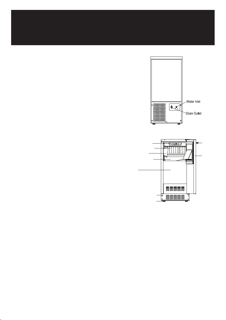
DESIGN 2 – For articulated hinge models
1. Pull the top decoration cover (3) upward and
remove it. Remove the cover caps (2) and then
remove the door by unscrewing the four screws
(1). Be careful to hold the door firmly after
2. removing the screws and place it on a padded
surface to avoid the risk of damage. Leave the
hinges open. (Figure 1)
3. Unscrew the four screws (4) to remove the top
and bottom articulated hinges. (Figure 2)
4. Pop out the cover caps on the left side of the
cabinet and use them to cover the screw holes
on the right-hand side.
5. Pull the top decoration cover (5) upward and remove it. Unscrew the two screws (6) and transfer the
retaining bracket (7) to the opposite side of the door. Refit the top decoration cover (5). (Figure 3)
6. Unscrew the screw (9) and transfer the bottom decoration cover (8) to the opposite side of the door.
(Figure 4)
7. Refit the articulated hinges to the opposite side of the door by using the four screws (3). (Repeat
step 2 in reverse.)
8. Refit the door to the opposite side. Then screw and tighten it after the door is leveled. (Repeat step 1
in reverse.)
DESIGN 3 – For panel ready models
1. Pull the top decoration cover (3) upward and
remove it. Remove the cover caps (2) and then
remove the door by unscrewing the four screws
(1). Be careful to hold the door firmly after
removing the screws and place it on a padded
surface to avoid the risk of damage. Leave the
hinges open. (Figure 1)
2. Unscrew the four screws (4) to remove the top
and bottom articulated hinges. (Figure 2)
3. Pop out the cover caps on the left side of the cabinet and use them to cover the screw holes on the
right-hand side.
4. Unscrew the two screws (5) and transfer the retaining bracket (6) to the opposite side of the door.
(Figure 3)
5. Refit the articulated hinges to the opposite side of the door by using the four screws (3). (Repeat
step 2 in reverse.)
6. Refit the door to the opposite side. Then screw and tighten it after the door is leveled. (Repeat step 1
in reverse.)
7. Refit the alternative top decoration cover included in the fittings on the top of door.
OVERLAY PANEL INSTALLATION INSTRUCTION
Door Panel Preparation
Depending on the model prepare the overlay panel to
the dimensions shown below. Then attach the handle
to the overlay panel by using the flat head screws and
drive the screws flush with the panel if needed.
NOTE:
H can be 28⅜" and 30". It depends on the actual product specification.
Weight of the overlay panel should not exceed 22 Lbs.
It is important to ensure that all drilled holes are drilled to the correct depth in order to
avoid splits in the wood when hardware is installed.
Drill the handle installation holes in the overlay panel according to the handle you are
planning to use. If reusing the handles came with the unit, drill two holes with holes
distance same as handle and diameter 5mm in the overlay panel.
use an extension cord with this appliance. However, if you must use an extension cord it is absolutely
necessary that it be a UL/CUL-listed, 3-wire grounding type appliance extension cord having a grounding
type plug and outlet and that the electrical rating of the cord be 115 volts and at least 10 amperes.
INSTALLING THE HANDLE
IMPORTANT: Do not overtighten the screws & do not use
power tools to install the handle.
DESIGN 1 –
Locate the handle (2) over the mounting stubs (1) of the
door and tighten the grub screws (3) with an Allen key to
secure the handle.
DESIGN 2 –
Remove the door gasket on the side you wish to install the
handle - you can see two designated holes for handle
installation.
Install the handle (3) tightly as shown above with two
screws (1) and flat washers (2) provided.
Replace the door gasket.
REVERSING THE DOOR HINGE
It is possible to reverse the door on this appliance, if
required.
To do so, follow the steps below:
Note: All parts removed must be saved to do the reinstallation of the door.
DESIGN 1 – For standard hinge models
1. Remove the bottom hinge (1) by unscrewing the
two lock screws (2). Be careful to hold the door
firmly after removing the screws. (Fig. 1)
2. Gently pull down to remove the door (3) from the
right top hinge and place it on a padded surface
to avoid the risk of damage. Then remove the
right top hinge (3). (Fig. 2 & 3)
3. Pop out the cover caps on the left side of cabinet
and use them to cover the screw holes on the
right hand side.
4. Screw the alternative left top hinge (4), included
in the fittings, on the left hand side of cabinet.
(Fig. 3)
5. Relocate the door to the designated position. Then screw the bottom hinge assembly on the left
designated position and tighten it after the door is leveled.
NOTE: Make sure that the socket and ON/OFF switch are easily accessible after the appliance has been
installed.
BUILT-UNDER INSTRUCTIONS
Make sure your installation does not block the front ventilation grill. If the unit is fully integrated to be
installed for fitting kitchen, make sure that the ventilation gaps in the plinth are at least 300 square
centimeters and remove the ventilation grilles, so that warm air can disperse unhindered. Otherwise the
appliance has to work harder, resulting in an increase in electricity consumption.
NOTE: When pushing the appliance into the niche, make sure that the mains cable does not get trapped.
CAUTION
To ensure the proper functioning of the appliance, air vents should never be blocked or covered.
ELECTRICAL CONNECTION
Check that the voltage marked on the product corresponds with your supply voltage
WARNING
Improper use of the grounded plug can result in the risk of electrical shock. If the power cord is damaged,
have it replaced by a qualified electrician or an authorized service center.
This appliance should be properly grounded for your safety. The power cord of this appliance is equipped
with a three-prong plug which mates with standard three-prong wall outlets to minimize the possibility of
electrical shock.
Do not under any circumstances cut or remove the third (ground) prong from the power cord supplied.
For personal safety, this appliance must be properly grounded.
This appliance requires a standard 115/120 Volt AC ~ 60Hz three-prong grounded electrical outlet. Have
the wall outlet and circuit checked by a qualified electrician to make sure the outlet is properly grounded.
When a standard 2-prong wall outlet is encountered, it is your responsibility and obligation to have it
replaced with a properly grounded 3-prong wall outlet.
To prevent accidental injury, the cord should be secured behind the appliance and not left exposed or
dangling.
The appliance should always be plugged into its own individual electrical outlet which has a voltage
rating that matches the rating label on the appliance. This provides the best performance and also
prevents overloading house wiring circuits that could cause a fire hazard from overheating. Never unplug
the appliance by pulling on the power cord. Always grip the plug firmly and pull straight out from the
receptacle. Repair or replace immediately all power cords that have become frayed or otherwise
damaged. Do not use a cord that shows cracks or abrasion damage along its length or at either end.
When moving the appliance, be careful not to damage the power cord.
EXTENSION CORD
Because of potential safety hazards under certain conditions, it is strongly recommended that you do not
DANGER
IMPORTANT - Risk of child entrapment! Child entrapment and suffocation are not problems of the past.
Junked or abandoned appliances are still dangerous, even if they will "just sit in the garage a few days".
Before discarding your old refrigerator:
• Take off the doors.
• Leave the shelves in place so that children may not easily climb inside.
• Cut the power off before plug and discard them.
• Cut the power cable off and discard it separately from the old appliance.
IMPORTANT: To avoid the possibility of explosion or fire, do not store or use combustible, flammable or
explosive vapors and liquids (such as gasoline) or explosive substances such as aerosols cans with a
flammable propellant in this appliance or in the vicinity of this or any other appliance.
WARNING
IMPORTANT: This appliance is equipped with a three prong grounding electric plug for protection against
possible electric shock hazards. It must be plugged into a dedicated, grounded electrical outlet. If only a
two prong electrical outlet is available, it is the responsibility of the customer to have it replaced with a
dedicated, properly grounded three prong electrical outlet.
• DO NOT cut or remove the third (ground) prong from the power cord.
• DO NOT use an adapter.
• DO NOT use a power cord that is frayed or damaged.
• DO NOT connect the appliance to an extension cord.
• Keep the power cord away from heated surfaces.
NOTE: Use of an electrical outlet with a ground fault interrupter (GFI) is not recommended.
State of California Proposition 65 Warnings:
WARNING: This product may contain one or more chemicals known to the State of California to cause
cancer.
WARNING: This product may contain one or more chemicals known to the State of California to cause birth
defects or other reproductive harm.
• If you receive a damaged product, immediately contact your dealer or builder. Do not install or use a
damaged appliance.
• This appliance is not intended for use by persons (including children) with reduced physical,
sensory or mental capabilities, or lack of experience and knowledge, unless they have been given
supervision or instruction concerning use of the appliance by a person responsible for their safety.
• Children should be supervised to ensure that they do not play with the appliance.
• Make sure that this appliance has been properly installed according to the installation section.
Make sure you know the location of the electrical outlet so that you know where and how to
disconnect power. Making sure the appliance is properly installed is the responsibility of the
customer.
• This appliance is not designed for installation in a recreational vehicle or boat.
Door
Handle
Ice Scoop
Adjustable Legs
Water Trough
Water Shutters
Ventilation Grille
Bin
Control Panel
• To prevent personal injury, property damage or damage to the unit, this appliance should only be
unpacked and set up by two people according to the installation section.
• Refrigeration equipment must be properly disposed of in a professional and appropriate way, in
accordance with the current local regulations and laws which protects the environment. This
applies to your old appliance and to your new unit once it has reached the end of its service life. DO
NOT dispose of the appliance in a landfill as the insulation (Cyclopentane) and refrigerant gas
(R600a) contained in these appliances are flammable.
• Do not install or use outdoors or in wet conditions for indoor use only products.
• Do not place another appliance on top of the appliance.
• Keep packaging materials away from children. Plastic sheets and bags can cause suffocation.
• Connect this appliance to a 115 Vac, 15 Amp. circuit that is controlled by a circuit breaker or fuse.
This appliance should have its own separate grounded circuit.
• Do not kink or pinch the power supply cord of the appliance. Never unplug the appliance by pulling
on the power cord. Always grip the plug firmly and pull straight out from the electrical outlet.
• To avoid and electric shock hazard, do not operate this appliance with wet hands, or while standing
in water or on a wet surface.
• Disconnect this appliance when not in use.
• Do not install, repair or replace any part of the appliance unless specifically recommended in the
service manual. A qualified service technician should perform all other service. Disconnect the unit
from the electrical outlet before performing any type of service.
• Use this appliance only for its intended purpose.
• Never allow children to operate, play with or crawl inside the appliance.
• Never allow anyone, including children to stand, sit or climb on any part of the appliance, including
the door. Doing so may cause damage, serious injury or death.
• If the power cord is damaged, it must be replaced by the manufacturer or a qualified service
technician in order to avoid a safety hazard.
• Do not tamper with the controls.
Warning: Risk of Fire/Flammable Materials.
• This appliance is CFC and HFC free and contains small quantities of Isobutane (R600a), which is
environmentally friendly, but flammable. Care must be taken during transportation and setting up of
the appliance so that no parts of the cooling system are damaged. Leaking coolant can ignite and
may damage the eyes. In the event of any damage:
- Avoid open flames and anything which creates a spark.
- Disconnect the power cord from the electrical outlet.
- Air the room in which the appliance is located for several minutes and contact the Customer
Service for advice.
• The more coolant there is in an appliance, the larger the room it should be installed in. In the event
of a leakage, if the appliance is in a small room, there is the danger of combustible gases building
up. For every ounce of coolant, at least 325 cubic feet of room space is required. The amount of
coolant in the appliance is stated on the data label inside the door. It is hazardous for anyone other
than factory authorized service personnel to carry out service or repairs on this appliance.
• Replacing components parts and servicing shall be done by factory authorized service personnel,
so as to minimize the risk of possible ignition due to incorrect parts or improper service
• Take seriously care when handling, moving, and use of the appliance to avoid either damaging the
refrigerant tubing, or increasing the risk of a leak.
• Replace all parts and panels before operating.
• WARNING: Keep ventilation openings, in the appliance enclosure or in the built-in structure, clear of
obstruction.
• WARNING: Do not use mechanical devices or other means to accelerate the defrosting process,
other than those recommended by the manufacturer.
• WARNING: Do not damage the refrigerant circuit. Do not pierce or burn.
• WARNING: Do not use electrical appliances inside the food storage compartments of the appliance,
unless they are of the type recommended by the manufacturer.
• Keep fingers out of the “pinch point” areas. Clearances between the doors and between the doors
and cabinet are necessarily small. Be careful closing doors when children are in the area.
• Do not cover shelves with aluminum foil or any other shelf material which may prevent air circula-
tion.
• WARNING: Connect to potable water supply only.
• WARNING: The appliance shall be stored in a room without continuously operating ignition sources
(for example: open flames, an operating gas appliance or an operating electric heater).
• WARNING: Be aware that refrigerants may not contain an odour.
• WARNING: In order to reduce flammability hazards the installation of this appliance must only be
carried out by a suitably qualified person.
• WARNING: Flammable Refrigerant Used. Components parts shall be replaced with like components
so as to minimize the risk of possible ignition due to incorrect parts.
CAUTION
• In the event of a power outage, minimize opening the door.
• Do not allow the ventilation grill below the door to become obstructed. Make sure there is always
good ventilation in front of the appliance.
• If your model requires defrosting, never use an ice pick or other sharp instrument to help speed up
defrosting. These instruments can puncture the inner lining or damage cooling unit.
• Do not use solvent-based cleaning agents or abrasives on the interior. These cleaners may damage
or discolor the interior.
• Use two or more people to move and install appliance. Failure to do so can result in back or other
injury.
• Never keep anything in the ice storage bin that is not ice. Objects like wine or beer bottles are not
only unsanitary, but the labels can slip off and plug up the drain.
• The appliance is intended to be permanently connected to the water mains and not connected by a
hose-set.
• Caution: Serving must be performed only as recommended by the manufacturer.
Disposal
• Dispose of your appliance packaging properly. Ensure that any plastic wrappings, bags etc. are
disposed of safely and kept out of the reach of babies and young children. Danger of suffocation!
•
• Refrigeration equipment must be properly disposed of in a professional and appropriate way, in
accordance with the current local regulations and laws which protects the environment this applies
to your old appliance and to your new unit once it has reached the end of its service life.
•
• WARNING: Please ensure that old, worn appliances are rendered unusable before disposal by
removing the doors, removing the plug, cutting the network cable, and removing or destroying any
snap fastenings or bolts. You will thus prevent children from locking themselves in the appliance
during play (risk of suffocation) or endangering their lives in any other way. DO NOT dispose of the
appliance in landfill as the insulation (Cyclopentane) and refrigerant gas (R600a) contained in these
appliances are flammable.
•
• Disposal instructions:
•
• The appliance must not be disposed of in the dustbin or with normal household rubbish.
• The coolant circuit, particularly the heat exchanger at the back/bottom of the unit, must not be
damaged.
• This product is not to be handled as normal household waste but is to be taken to a recycling
collection point for electrical and electronic goods. By correctly disposing of this product you are
contributing to the protection of the environment and to the health of your fellow human beings.
Improper disposal endangers health and the environment. Further information about the recycling
of the product may be obtained from your town hall, refuse collection department or the store
where you purchased the product.
• Built-in or Free-standing installation Ice Machine.
• Self-contained and air-cooled.
• Electronic control with digital display and touchpad
input.
• ON/OFF Power Switch.
• Select/Harvest, Cleaning and Delay Start functions.
• Idle mode (Delay Start) – 10-Hour temporary shut down.
• Cleaning alarm.
• Shabbos mode for certain religious observances. Mode
memory function - if power is interrupted (power surge,
breaker switch, etc.) and then powered up again, the unit
will operate with the last mode set-point.
• Crystal clear ice cubes.
• Integrated drain pump (Factory installed) for IM60.
• Gravity-assisted drain required for IM-30.
• Commercial grade, heavy duty circulation pump.
• No defrosting required.
• Heavy duty ice scoop included.
• Visual and audible malfunction warning system.
• Reversible door.
• Black coated metal sheet outer frame and white plastic
interior liner offer lifetime performance and stability.
• Environmentally friendly refrigerant and foaming
insulation gas.
NOTE: Features and specifications are subject to change
without notice.
PRODUCT FEATURES
BEFORE USING YOUR APPLIANCE
- Remove all exterior and interior packing. Clean the interior surface with lukewarm water using a soft
cloth. The unit may have residual odors at first, they will disappear as the unit cools.
- IMPORTANT: Before connecting the icemachine to the power source, let it stand upright for
approximately 24 hours. This will reduce the possibility of a malfunction in the cooling system
caused by handling during transportation.
- The door on this appliance can be opened either the left or the right side. The unit is delivered with
the door opening on the left side. Should you wish to open the door from the right, follow the
instructions "Reversing the door hinge".
- Install the handle on the door.
- Sanitize the ice machine. All ice machines are factory-operated and adjusted before shipment.
Normally, new installations do not require any adjustment.
INSTALLATION OF YOUR APPLIANCE
WARNING
This appliance must be installed in accordance with all local codes and ordinances.
• The appliances are designed to be built-in or recessed or free-standing installation.
• This ice machine should be properly installed by qualified personnel.
• WARNING: Flammable Refrigerant Used. Appliance should be installed in accordance with the
Safety Standard for Refrigeration Systems, ANSI/ASHRAE 15.
• Place your ice machine on a floor that is even and strong enough to support it when it is fully loaded.
It is very important for the ice machine to be level in order to work properly. To level your unit, adjust
the front adjustable legs at the bottom of the unit.
• For freestanding installation, 5 inches (127mm) of space between the back and sides of the unit are
suggested, which allows the proper air circulation to cool the compressor and condenser for energy
saving. Even for built-in installation, it is a must to keep ¾" (5mm) space on each side and at the top
to ensure proper service access and efficient ventilation. Take care that the air vent at the front of
the appliance must never be covered or blocked in any way.
• Installation of the ice maker requires a cold water supply inlet of ¼-in. (6.35mm) soft copper tubing
with a shut-off valve.
• Locate the unit away from direct sunlight and sources of heat (stove, heater, radiator, etc.). Direct
sunlight may affect the acrylic coating and heat sources may increase electrical consumption.
Extreme cold ambient temperatures may also cause the unit not to perform properly.
• Avoid locating the unit in damp areas.
• Plug the unit into an exclusive, easily accessible and properly grounded wall outlet. Do not under any
circumstances cut or remove the third (ground) prong from the power cord. Any questions concern-
ing power and/or earthing should be directed towards a qualified electrician or an authorized
products service centre.
• The appliance must be installed to all electrical, plumbing, water and drain connections in
accordance with state and local codes.
• The equipment must be installed with adequate backflow protection to comply with applicable
federal, state and local codes.
• It is strongly recommended that a water filter be used. A filter, if it is of the proper type, can remove
taste and odors as well as particles. Some water is very hard, and softened water may result in
white, mushy cubes that stick together. Deionized water is not recommended.
Door Panel Installation
Attach the wood overlay panel (1) on the door (2) by using the four wood screws ST4x15 Type AB Philips
(3).
WATER SUPPLY AND DRAIN REQUIREMENTS
Prepare water supply line and drain before installation of your ice machine. Installation requires a 1/4" ID
copper cold water line and compression fitting (not supplied).
The ice machine IM50 is supplied with an automatic drain pump system. The ice machine IM30 is
supplied with a drain hose for gravity draining. Both drain methods require routing to an open site drain.
Do not connect directly to drain line as bacteria from drain line may contaminate the ice machine.
Make certain the hoses are not pinched or kinked or damaged during installation.
Check for leaks after connection.
WATER INLET LINES
CAUTION
Copper tubing is recommended for the water supply line. Water supply tubing made of 1/4" plastic is not
recommended since it greatly increases the potential for water leaks. Manufacturer will not be responsible
for any damage if plastic tubing is used for the supply line.
Follow these guidelines to install water inlet lines:
▪ Do not connect the ice machine to a hot water supply. Be sure all hot water restrictors installed for
other equipment are working. (Check valves on sink faucets, dishwashers, etc.)
▪ If water pressure exceeds the maximum recommended pressure (80 psi - 55 bar), obtain a water
pressure regulator.
▪ Install a water shut-off valve for the ice making water lines.
▪ Insulate the water inlet line to prevent condensation.
▪ Install tubing only in areas where temperatures will remain above freezing.
▪ Leave a coil of copper tubing to allow the ice maker to be pulled out of the cabinet or away from the
wall for service.
DRAIN CONNECTIONS (FACTORY SUPPLIED)
Follow these guidelines when installing drain lines to prevent drain water from flowing back into the ice
machine and storage bin:
▪ Drain lines must have a 1.5 inch drop per 5 feet of run (2.5 cm per meter), and must not create traps.
▪ The floor drain must be large enough to accommodate drainage from all drains.
▪ Drain pump discharge line must terminate at an open site drain.
▪ The maximum length of drain hose is 5 feet (1.5
m).
▪ The maximum rise of drain hose is 2.6 feet (0.8
m).
▪ Pour 3000ml of water into the ice storage bin to
check for leaks in the drainage system.
WATER SUPPLY AND DRAIN LINE
SIZING/CONNECTIONS
CAUTION
Plumbing must conform to state and local codes.
NOTE: If air temperature is less than 60°F (15.5°C), water
temperature must be equal to or greater than 50°F (10°C).
INSTALLATION PROCEDURE
1. Prepare the site by following the instructions under Electrical Connection and Water Supply and
Drain Requirements.
2. Remove ice machine from carton.
3. Inspect for damage.
4. Remove literature packet and drain hose from inside the ice machine.
5. Adjust leg levelers.
6. Reverse door if desired. See Reversing the Door Hinge.
7. Install drain hose to drain on back of ice machine and route to open site drain.
8. Use compression fitting to connect the Water Inlet on back of ice machine to the prepared 1/4" ID
cold water line.
9. Open the shut-off valve on the water line.
10. Connect electrical plug to grounded (three-prong), polarized outlet.
11. Place ice machine back in position and check leveling again. Make any necessary adjustments.
12. Prepare sanitizer solution and sanitize the ice machine according to Cleaning/Sanitizing the Ice
Making System.
13. At initial start-up, ice machine will need approximately 45 minutes to freeze.
INSTALLATION CHECK LIST
▪ Is the Ice Machine level?!
▪ Has all of the packing been removed?
▪ Have all of the electrical and water connections been made?
▪ Has the supply voltage been tested and checked against the rating on the nameplate?
▪ Is there proper clearance around the ice machine for air circulation?
▪ Has the ice machine been installed where ambient temperatures will remain in the range of 41° -
100°F (5° - 38°C)?
▪ Has the ice machine been installed where the incoming water temperature will remain in the range
of 41° - 90°F (5° - 32°C)?
▪ Has the water supply pressure been checked to ensure a minimum of 20 psig with a static pressure
not to exceed 80 psig?
▪ Is the ice machine drain line routed to an open site drain?
▪ Are all electrical leads free from contact with refrigeration lines and moving equipment?
▪ Has the ice machine and bin been sanitized?
▪ Is the ice machine plugged into a properly grounded, polarized receptacle?
▪ Have the water and drain connections been examined for leaks?
6

DESIGN 2 – For articulated hinge models
1. Pull the top decoration cover (3) upward and
remove it. Remove the cover caps (2) and then
remove the door by unscrewing the four screws
(1). Be careful to hold the door firmly after
2. removing the screws and place it on a padded
surface to avoid the risk of damage. Leave the
hinges open. (Figure 1)
3. Unscrew the four screws (4) to remove the top
and bottom articulated hinges. (Figure 2)
4. Pop out the cover caps on the left side of the
cabinet and use them to cover the screw holes
on the right-hand side.
5. Pull the top decoration cover (5) upward and remove it. Unscrew the two screws (6) and transfer the
retaining bracket (7) to the opposite side of the door. Refit the top decoration cover (5). (Figure 3)
6. Unscrew the screw (9) and transfer the bottom decoration cover (8) to the opposite side of the door.
(Figure 4)
7. Refit the articulated hinges to the opposite side of the door by using the four screws (3). (Repeat
step 2 in reverse.)
8. Refit the door to the opposite side. Then screw and tighten it after the door is leveled. (Repeat step 1
in reverse.)
DESIGN 3 – For panel ready models
1. Pull the top decoration cover (3) upward and
remove it. Remove the cover caps (2) and then
remove the door by unscrewing the four screws
(1). Be careful to hold the door firmly after
removing the screws and place it on a padded
surface to avoid the risk of damage. Leave the
hinges open. (Figure 1)
2. Unscrew the four screws (4) to remove the top
and bottom articulated hinges. (Figure 2)
3. Pop out the cover caps on the left side of the cabinet and use them to cover the screw holes on the
right-hand side.
4. Unscrew the two screws (5) and transfer the retaining bracket (6) to the opposite side of the door.
(Figure 3)
5. Refit the articulated hinges to the opposite side of the door by using the four screws (3). (Repeat
step 2 in reverse.)
6. Refit the door to the opposite side. Then screw and tighten it after the door is leveled. (Repeat step 1
in reverse.)
7. Refit the alternative top decoration cover included in the fittings on the top of door.
OVERLAY PANEL INSTALLATION INSTRUCTION
Door Panel Preparation
Depending on the model prepare the overlay panel to
the dimensions shown below. Then attach the handle
to the overlay panel by using the flat head screws and
drive the screws flush with the panel if needed.
NOTE:
H can be 28⅜" and 30". It depends on the actual product specification.
Weight of the overlay panel should not exceed 22 Lbs.
It is important to ensure that all drilled holes are drilled to the correct depth in order to
avoid splits in the wood when hardware is installed.
Drill the handle installation holes in the overlay panel according to the handle you are
planning to use. If reusing the handles came with the unit, drill two holes with holes
distance same as handle and diameter 5mm in the overlay panel.
use an extension cord with this appliance. However, if you must use an extension cord it is absolutely
necessary that it be a UL/CUL-listed, 3-wire grounding type appliance extension cord having a grounding
type plug and outlet and that the electrical rating of the cord be 115 volts and at least 10 amperes.
INSTALLING THE HANDLE
IMPORTANT: Do not overtighten the screws & do not use
power tools to install the handle.
DESIGN 1 –
Locate the handle (2) over the mounting stubs (1) of the
door and tighten the grub screws (3) with an Allen key to
secure the handle.
DESIGN 2 –
Remove the door gasket on the side you wish to install the
handle - you can see two designated holes for handle
installation.
Install the handle (3) tightly as shown above with two
screws (1) and flat washers (2) provided.
Replace the door gasket.
REVERSING THE DOOR HINGE
It is possible to reverse the door on this appliance, if
required.
To do so, follow the steps below:
Note: All parts removed must be saved to do the reinstallation of the door.
DESIGN 1 – For standard hinge models
1. Remove the bottom hinge (1) by unscrewing the
two lock screws (2). Be careful to hold the door
firmly after removing the screws. (Fig. 1)
2. Gently pull down to remove the door (3) from the
right top hinge and place it on a padded surface
to avoid the risk of damage. Then remove the
right top hinge (3). (Fig. 2 & 3)
3. Pop out the cover caps on the left side of cabinet
and use them to cover the screw holes on the
right hand side.
4. Screw the alternative left top hinge (4), included
in the fittings, on the left hand side of cabinet.
(Fig. 3)
5. Relocate the door to the designated position. Then screw the bottom hinge assembly on the left
designated position and tighten it after the door is leveled.
NOTE: Make sure that the socket and ON/OFF switch are easily accessible after the appliance has been
installed.
BUILT-UNDER INSTRUCTIONS
Make sure your installation does not block the front ventilation grill. If the unit is fully integrated to be
installed for fitting kitchen, make sure that the ventilation gaps in the plinth are at least 300 square
centimeters and remove the ventilation grilles, so that warm air can disperse unhindered. Otherwise the
appliance has to work harder, resulting in an increase in electricity consumption.
NOTE: When pushing the appliance into the niche, make sure that the mains cable does not get trapped.
CAUTION
To ensure the proper functioning of the appliance, air vents should never be blocked or covered.
ELECTRICAL CONNECTION
Check that the voltage marked on the product corresponds with your supply voltage
WARNING
Improper use of the grounded plug can result in the risk of electrical shock. If the power cord is damaged,
have it replaced by a qualified electrician or an authorized service center.
This appliance should be properly grounded for your safety. The power cord of this appliance is equipped
with a three-prong plug which mates with standard three-prong wall outlets to minimize the possibility of
electrical shock.
Do not under any circumstances cut or remove the third (ground) prong from the power cord supplied.
For personal safety, this appliance must be properly grounded.
This appliance requires a standard 115/120 Volt AC ~ 60Hz three-prong grounded electrical outlet. Have
the wall outlet and circuit checked by a qualified electrician to make sure the outlet is properly grounded.
When a standard 2-prong wall outlet is encountered, it is your responsibility and obligation to have it
replaced with a properly grounded 3-prong wall outlet.
To prevent accidental injury, the cord should be secured behind the appliance and not left exposed or
dangling.
The appliance should always be plugged into its own individual electrical outlet which has a voltage
rating that matches the rating label on the appliance. This provides the best performance and also
prevents overloading house wiring circuits that could cause a fire hazard from overheating. Never unplug
the appliance by pulling on the power cord. Always grip the plug firmly and pull straight out from the
receptacle. Repair or replace immediately all power cords that have become frayed or otherwise
damaged. Do not use a cord that shows cracks or abrasion damage along its length or at either end.
When moving the appliance, be careful not to damage the power cord.
EXTENSION CORD
Because of potential safety hazards under certain conditions, it is strongly recommended that you do not
INSTALLATION
BEFORE USING YOUR APPLIANCE
- Remove all exterior and interior packing. Clean the interior surface with lukewarm water using a soft
cloth. The unit may have residual odors at first, they will disappear as the unit cools.
- IMPORTANT: Before connecting the icemachine to the power source, let it stand upright for
approximately 24 hours. This will reduce the possibility of a malfunction in the cooling system
caused by handling during transportation.
- The door on this appliance can be opened either the left or the right side. The unit is delivered with
the door opening on the left side. Should you wish to open the door from the right, follow the
instructions "Reversing the door hinge".
- Install the handle on the door.
- Sanitize the ice machine. All ice machines are factory-operated and adjusted before shipment.
Normally, new installations do not require any adjustment.
INSTALLATION OF YOUR APPLIANCE
WARNING
This appliance must be installed in accordance with all local codes and ordinances.
• The appliances are designed to be built-in or recessed or free-standing installation.
• This ice machine should be properly installed by qualified personnel.
• WARNING: Flammable Refrigerant Used. Appliance should be installed in accordance with the
Safety Standard for Refrigeration Systems, ANSI/ASHRAE 15.
• Place your ice machine on a floor that is even and strong enough to support it when it is fully loaded.
It is very important for the ice machine to be level in order to work properly. To level your unit, adjust
the front adjustable legs at the bottom of the unit.
• For freestanding installation, 5 inches (127mm) of space between the back and sides of the unit are
suggested, which allows the proper air circulation to cool the compressor and condenser for energy
saving. Even for built-in installation, it is a must to keep ¾" (5mm) space on each side and at the top
to ensure proper service access and efficient ventilation. Take care that the air vent at the front of
the appliance must never be covered or blocked in any way.
• Installation of the ice maker requires a cold water supply inlet of ¼-in. (6.35mm) soft copper tubing
with a shut-off valve.
• Locate the unit away from direct sunlight and sources of heat (stove, heater, radiator, etc.). Direct
sunlight may affect the acrylic coating and heat sources may increase electrical consumption.
Extreme cold ambient temperatures may also cause the unit not to perform properly.
• Avoid locating the unit in damp areas.
• Plug the unit into an exclusive, easily accessible and properly grounded wall outlet. Do not under any
circumstances cut or remove the third (ground) prong from the power cord. Any questions concern-
ing power and/or earthing should be directed towards a qualified electrician or an authorized
products service centre.
• The appliance must be installed to all electrical, plumbing, water and drain connections in
accordance with state and local codes.
• The equipment must be installed with adequate backflow protection to comply with applicable
federal, state and local codes.
• It is strongly recommended that a water filter be used. A filter, if it is of the proper type, can remove
taste and odors as well as particles. Some water is very hard, and softened water may result in
white, mushy cubes that stick together. Deionized water is not recommended.
Door Panel Installation
Attach the wood overlay panel (1) on the door (2) by using the four wood screws ST4x15 Type AB Philips
(3).
WATER SUPPLY AND DRAIN REQUIREMENTS
Prepare water supply line and drain before installation of your ice machine. Installation requires a 1/4" ID
copper cold water line and compression fitting (not supplied).
The ice machine IM50 is supplied with an automatic drain pump system. The ice machine IM30 is
supplied with a drain hose for gravity draining. Both drain methods require routing to an open site drain.
Do not connect directly to drain line as bacteria from drain line may contaminate the ice machine.
Make certain the hoses are not pinched or kinked or damaged during installation.
Check for leaks after connection.
WATER INLET LINES
CAUTION
Copper tubing is recommended for the water supply line. Water supply tubing made of 1/4" plastic is not
recommended since it greatly increases the potential for water leaks. Manufacturer will not be responsible
for any damage if plastic tubing is used for the supply line.
Follow these guidelines to install water inlet lines:
▪ Do not connect the ice machine to a hot water supply. Be sure all hot water restrictors installed for
other equipment are working. (Check valves on sink faucets, dishwashers, etc.)
▪ If water pressure exceeds the maximum recommended pressure (80 psi - 55 bar), obtain a water
pressure regulator.
▪ Install a water shut-off valve for the ice making water lines.
▪ Insulate the water inlet line to prevent condensation.
▪ Install tubing only in areas where temperatures will remain above freezing.
▪ Leave a coil of copper tubing to allow the ice maker to be pulled out of the cabinet or away from the
wall for service.
DRAIN CONNECTIONS (FACTORY SUPPLIED)
Follow these guidelines when installing drain lines to prevent drain water from flowing back into the ice
machine and storage bin:
▪ Drain lines must have a 1.5 inch drop per 5 feet of run (2.5 cm per meter), and must not create traps.
▪ The floor drain must be large enough to accommodate drainage from all drains.
▪ Drain pump discharge line must terminate at an open site drain.
▪ The maximum length of drain hose is 5 feet (1.5
m).
▪ The maximum rise of drain hose is 2.6 feet (0.8
m).
▪ Pour 3000ml of water into the ice storage bin to
check for leaks in the drainage system.
WATER SUPPLY AND DRAIN LINE
SIZING/CONNECTIONS
CAUTION
Plumbing must conform to state and local codes.
NOTE: If air temperature is less than 60°F (15.5°C), water
temperature must be equal to or greater than 50°F (10°C).
INSTALLATION PROCEDURE
1. Prepare the site by following the instructions under Electrical Connection and Water Supply and
Drain Requirements.
2. Remove ice machine from carton.
3. Inspect for damage.
4. Remove literature packet and drain hose from inside the ice machine.
5. Adjust leg levelers.
6. Reverse door if desired. See Reversing the Door Hinge.
7. Install drain hose to drain on back of ice machine and route to open site drain.
8. Use compression fitting to connect the Water Inlet on back of ice machine to the prepared 1/4" ID
cold water line.
9. Open the shut-off valve on the water line.
10. Connect electrical plug to grounded (three-prong), polarized outlet.
11. Place ice machine back in position and check leveling again. Make any necessary adjustments.
12. Prepare sanitizer solution and sanitize the ice machine according to Cleaning/Sanitizing the Ice
Making System.
13. At initial start-up, ice machine will need approximately 45 minutes to freeze.
INSTALLATION CHECK LIST
▪ Is the Ice Machine level?!
▪ Has all of the packing been removed?
▪ Have all of the electrical and water connections been made?
▪ Has the supply voltage been tested and checked against the rating on the nameplate?
▪ Is there proper clearance around the ice machine for air circulation?
▪ Has the ice machine been installed where ambient temperatures will remain in the range of 41° -
100°F (5° - 38°C)?
▪ Has the ice machine been installed where the incoming water temperature will remain in the range
of 41° - 90°F (5° - 32°C)?
▪ Has the water supply pressure been checked to ensure a minimum of 20 psig with a static pressure
not to exceed 80 psig?
▪ Is the ice machine drain line routed to an open site drain?
▪ Are all electrical leads free from contact with refrigeration lines and moving equipment?
▪ Has the ice machine and bin been sanitized?
▪ Is the ice machine plugged into a properly grounded, polarized receptacle?
▪ Have the water and drain connections been examined for leaks?
7
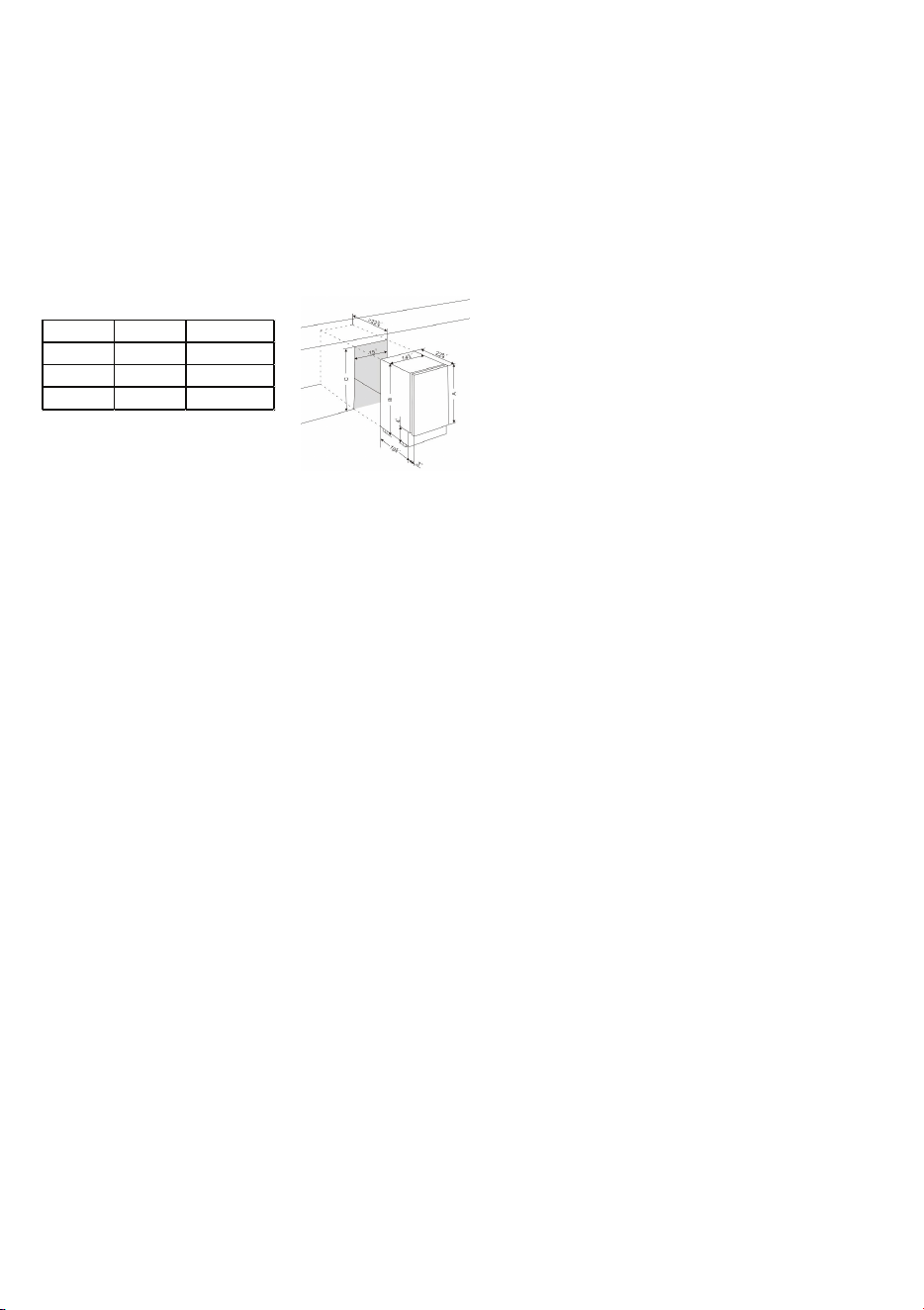
DESIGN 2 – For articulated hinge models
1. Pull the top decoration cover (3) upward and
remove it. Remove the cover caps (2) and then
remove the door by unscrewing the four screws
(1). Be careful to hold the door firmly after
2. removing the screws and place it on a padded
surface to avoid the risk of damage. Leave the
hinges open. (Figure 1)
3. Unscrew the four screws (4) to remove the top
and bottom articulated hinges. (Figure 2)
4. Pop out the cover caps on the left side of the
cabinet and use them to cover the screw holes
on the right-hand side.
5. Pull the top decoration cover (5) upward and remove it. Unscrew the two screws (6) and transfer the
retaining bracket (7) to the opposite side of the door. Refit the top decoration cover (5). (Figure 3)
6. Unscrew the screw (9) and transfer the bottom decoration cover (8) to the opposite side of the door.
(Figure 4)
7. Refit the articulated hinges to the opposite side of the door by using the four screws (3). (Repeat
step 2 in reverse.)
8. Refit the door to the opposite side. Then screw and tighten it after the door is leveled. (Repeat step 1
in reverse.)
DESIGN 3 – For panel ready models
1. Pull the top decoration cover (3) upward and
remove it. Remove the cover caps (2) and then
remove the door by unscrewing the four screws
(1). Be careful to hold the door firmly after
removing the screws and place it on a padded
surface to avoid the risk of damage. Leave the
hinges open. (Figure 1)
2. Unscrew the four screws (4) to remove the top
and bottom articulated hinges. (Figure 2)
3. Pop out the cover caps on the left side of the cabinet and use them to cover the screw holes on the
right-hand side.
4. Unscrew the two screws (5) and transfer the retaining bracket (6) to the opposite side of the door.
(Figure 3)
5. Refit the articulated hinges to the opposite side of the door by using the four screws (3). (Repeat
step 2 in reverse.)
6. Refit the door to the opposite side. Then screw and tighten it after the door is leveled. (Repeat step 1
in reverse.)
7. Refit the alternative top decoration cover included in the fittings on the top of door.
OVERLAY PANEL INSTALLATION INSTRUCTION
Door Panel Preparation
Depending on the model prepare the overlay panel to
the dimensions shown below. Then attach the handle
to the overlay panel by using the flat head screws and
drive the screws flush with the panel if needed.
NOTE:
H can be 28⅜" and 30". It depends on the actual product specification.
Weight of the overlay panel should not exceed 22 Lbs.
It is important to ensure that all drilled holes are drilled to the correct depth in order to
avoid splits in the wood when hardware is installed.
Drill the handle installation holes in the overlay panel according to the handle you are
planning to use. If reusing the handles came with the unit, drill two holes with holes
distance same as handle and diameter 5mm in the overlay panel.
use an extension cord with this appliance. However, if you must use an extension cord it is absolutely
necessary that it be a UL/CUL-listed, 3-wire grounding type appliance extension cord having a grounding
type plug and outlet and that the electrical rating of the cord be 115 volts and at least 10 amperes.
INSTALLING THE HANDLE
IMPORTANT: Do not overtighten the screws & do not use
power tools to install the handle.
DESIGN 1 –
Locate the handle (2) over the mounting stubs (1) of the
door and tighten the grub screws (3) with an Allen key to
secure the handle.
DESIGN 2 –
Remove the door gasket on the side you wish to install the
handle - you can see two designated holes for handle
installation.
Install the handle (3) tightly as shown above with two
screws (1) and flat washers (2) provided.
Replace the door gasket.
REVERSING THE DOOR HINGE
It is possible to reverse the door on this appliance, if
required.
To do so, follow the steps below:
Note: All parts removed must be saved to do the reinstallation of the door.
DESIGN 1 – For standard hinge models
1. Remove the bottom hinge (1) by unscrewing the
two lock screws (2). Be careful to hold the door
firmly after removing the screws. (Fig. 1)
2. Gently pull down to remove the door (3) from the
right top hinge and place it on a padded surface
to avoid the risk of damage. Then remove the
right top hinge (3). (Fig. 2 & 3)
3. Pop out the cover caps on the left side of cabinet
and use them to cover the screw holes on the
right hand side.
4. Screw the alternative left top hinge (4), included
in the fittings, on the left hand side of cabinet.
(Fig. 3)
5. Relocate the door to the designated position. Then screw the bottom hinge assembly on the left
designated position and tighten it after the door is leveled.
NOTE: Make sure that the socket and ON/OFF switch are easily accessible after the appliance has been
installed.
BUILT-UNDER INSTRUCTIONS
Make sure your installation does not block the front ventilation grill. If the unit is fully integrated to be
installed for fitting kitchen, make sure that the ventilation gaps in the plinth are at least 300 square
centimeters and remove the ventilation grilles, so that warm air can disperse unhindered. Otherwise the
appliance has to work harder, resulting in an increase in electricity consumption.
NOTE: When pushing the appliance into the niche, make sure that the mains cable does not get trapped.
CAUTION
To ensure the proper functioning of the appliance, air vents should never be blocked or covered.
ELECTRICAL CONNECTION
Check that the voltage marked on the product corresponds with your supply voltage
WARNING
Improper use of the grounded plug can result in the risk of electrical shock. If the power cord is damaged,
have it replaced by a qualified electrician or an authorized service center.
This appliance should be properly grounded for your safety. The power cord of this appliance is equipped
with a three-prong plug which mates with standard three-prong wall outlets to minimize the possibility of
electrical shock.
Do not under any circumstances cut or remove the third (ground) prong from the power cord supplied.
For personal safety, this appliance must be properly grounded.
This appliance requires a standard 115/120 Volt AC ~ 60Hz three-prong grounded electrical outlet. Have
the wall outlet and circuit checked by a qualified electrician to make sure the outlet is properly grounded.
When a standard 2-prong wall outlet is encountered, it is your responsibility and obligation to have it
replaced with a properly grounded 3-prong wall outlet.
To prevent accidental injury, the cord should be secured behind the appliance and not left exposed or
dangling.
The appliance should always be plugged into its own individual electrical outlet which has a voltage
rating that matches the rating label on the appliance. This provides the best performance and also
prevents overloading house wiring circuits that could cause a fire hazard from overheating. Never unplug
the appliance by pulling on the power cord. Always grip the plug firmly and pull straight out from the
receptacle. Repair or replace immediately all power cords that have become frayed or otherwise
damaged. Do not use a cord that shows cracks or abrasion damage along its length or at either end.
When moving the appliance, be careful not to damage the power cord.
EXTENSION CORD
Because of potential safety hazards under certain conditions, it is strongly recommended that you do not
BEFORE USING YOUR APPLIANCE
- Remove all exterior and interior packing. Clean the interior surface with lukewarm water using a soft
cloth. The unit may have residual odors at first, they will disappear as the unit cools.
- IMPORTANT: Before connecting the icemachine to the power source, let it stand upright for
approximately 24 hours. This will reduce the possibility of a malfunction in the cooling system
caused by handling during transportation.
- The door on this appliance can be opened either the left or the right side. The unit is delivered with
the door opening on the left side. Should you wish to open the door from the right, follow the
instructions "Reversing the door hinge".
- Install the handle on the door.
- Sanitize the ice machine. All ice machines are factory-operated and adjusted before shipment.
Normally, new installations do not require any adjustment.
INSTALLATION OF YOUR APPLIANCE
WARNING
This appliance must be installed in accordance with all local codes and ordinances.
• The appliances are designed to be built-in or recessed or free-standing installation.
• This ice machine should be properly installed by qualified personnel.
• WARNING: Flammable Refrigerant Used. Appliance should be installed in accordance with the
Safety Standard for Refrigeration Systems, ANSI/ASHRAE 15.
• Place your ice machine on a floor that is even and strong enough to support it when it is fully loaded.
It is very important for the ice machine to be level in order to work properly. To level your unit, adjust
the front adjustable legs at the bottom of the unit.
• For freestanding installation, 5 inches (127mm) of space between the back and sides of the unit are
suggested, which allows the proper air circulation to cool the compressor and condenser for energy
saving. Even for built-in installation, it is a must to keep ¾" (5mm) space on each side and at the top
to ensure proper service access and efficient ventilation. Take care that the air vent at the front of
the appliance must never be covered or blocked in any way.
• Installation of the ice maker requires a cold water supply inlet of ¼-in. (6.35mm) soft copper tubing
with a shut-off valve.
• Locate the unit away from direct sunlight and sources of heat (stove, heater, radiator, etc.). Direct
sunlight may affect the acrylic coating and heat sources may increase electrical consumption.
Extreme cold ambient temperatures may also cause the unit not to perform properly.
• Avoid locating the unit in damp areas.
• Plug the unit into an exclusive, easily accessible and properly grounded wall outlet. Do not under any
circumstances cut or remove the third (ground) prong from the power cord. Any questions concern-
ing power and/or earthing should be directed towards a qualified electrician or an authorized
products service centre.
• The appliance must be installed to all electrical, plumbing, water and drain connections in
accordance with state and local codes.
• The equipment must be installed with adequate backflow protection to comply with applicable
federal, state and local codes.
• It is strongly recommended that a water filter be used. A filter, if it is of the proper type, can remove
taste and odors as well as particles. Some water is very hard, and softened water may result in
white, mushy cubes that stick together. Deionized water is not recommended.
ADA Standard
A (inch) 28 30
B (inch) 32 34
C (inch) 34.5 34.5
Door Panel Installation
Attach the wood overlay panel (1) on the door (2) by using the four wood screws ST4x15 Type AB Philips
(3).
WATER SUPPLY AND DRAIN REQUIREMENTS
Prepare water supply line and drain before installation of your ice machine. Installation requires a 1/4" ID
copper cold water line and compression fitting (not supplied).
The ice machine IM50 is supplied with an automatic drain pump system. The ice machine IM30 is
supplied with a drain hose for gravity draining. Both drain methods require routing to an open site drain.
Do not connect directly to drain line as bacteria from drain line may contaminate the ice machine.
Make certain the hoses are not pinched or kinked or damaged during installation.
Check for leaks after connection.
WATER INLET LINES
CAUTION
Copper tubing is recommended for the water supply line. Water supply tubing made of 1/4" plastic is not
recommended since it greatly increases the potential for water leaks. Manufacturer will not be responsible
for any damage if plastic tubing is used for the supply line.
Follow these guidelines to install water inlet lines:
▪ Do not connect the ice machine to a hot water supply. Be sure all hot water restrictors installed for
other equipment are working. (Check valves on sink faucets, dishwashers, etc.)
▪ If water pressure exceeds the maximum recommended pressure (80 psi - 55 bar), obtain a water
pressure regulator.
▪ Install a water shut-off valve for the ice making water lines.
▪ Insulate the water inlet line to prevent condensation.
▪ Install tubing only in areas where temperatures will remain above freezing.
▪ Leave a coil of copper tubing to allow the ice maker to be pulled out of the cabinet or away from the
wall for service.
DRAIN CONNECTIONS (FACTORY SUPPLIED)
Follow these guidelines when installing drain lines to prevent drain water from flowing back into the ice
machine and storage bin:
▪ Drain lines must have a 1.5 inch drop per 5 feet of run (2.5 cm per meter), and must not create traps.
▪ The floor drain must be large enough to accommodate drainage from all drains.
▪ Drain pump discharge line must terminate at an open site drain.
▪ The maximum length of drain hose is 5 feet (1.5
m).
▪ The maximum rise of drain hose is 2.6 feet (0.8
m).
▪ Pour 3000ml of water into the ice storage bin to
check for leaks in the drainage system.
WATER SUPPLY AND DRAIN LINE
SIZING/CONNECTIONS
CAUTION
Plumbing must conform to state and local codes.
NOTE: If air temperature is less than 60°F (15.5°C), water
temperature must be equal to or greater than 50°F (10°C).
INSTALLATION PROCEDURE
1. Prepare the site by following the instructions under Electrical Connection and Water Supply and
Drain Requirements.
2. Remove ice machine from carton.
3. Inspect for damage.
4. Remove literature packet and drain hose from inside the ice machine.
5. Adjust leg levelers.
6. Reverse door if desired. See Reversing the Door Hinge.
7. Install drain hose to drain on back of ice machine and route to open site drain.
8. Use compression fitting to connect the Water Inlet on back of ice machine to the prepared 1/4" ID
cold water line.
9. Open the shut-off valve on the water line.
10. Connect electrical plug to grounded (three-prong), polarized outlet.
11. Place ice machine back in position and check leveling again. Make any necessary adjustments.
12. Prepare sanitizer solution and sanitize the ice machine according to Cleaning/Sanitizing the Ice
Making System.
13. At initial start-up, ice machine will need approximately 45 minutes to freeze.
INSTALLATION CHECK LIST
▪ Is the Ice Machine level?!
▪ Has all of the packing been removed?
▪ Have all of the electrical and water connections been made?
▪ Has the supply voltage been tested and checked against the rating on the nameplate?
▪ Is there proper clearance around the ice machine for air circulation?
▪ Has the ice machine been installed where ambient temperatures will remain in the range of 41° -
100°F (5° - 38°C)?
▪ Has the ice machine been installed where the incoming water temperature will remain in the range
of 41° - 90°F (5° - 32°C)?
▪ Has the water supply pressure been checked to ensure a minimum of 20 psig with a static pressure
not to exceed 80 psig?
▪ Is the ice machine drain line routed to an open site drain?
▪ Are all electrical leads free from contact with refrigeration lines and moving equipment?
▪ Has the ice machine and bin been sanitized?
▪ Is the ice machine plugged into a properly grounded, polarized receptacle?
▪ Have the water and drain connections been examined for leaks?
8
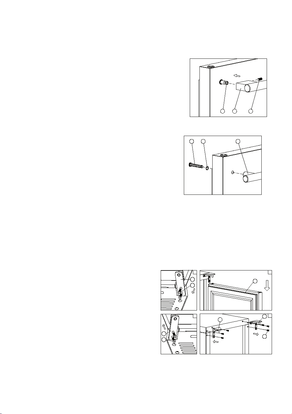
DESIGN 2 – For articulated hinge models
1. Pull the top decoration cover (3) upward and
remove it. Remove the cover caps (2) and then
remove the door by unscrewing the four screws
(1). Be careful to hold the door firmly after
2. removing the screws and place it on a padded
surface to avoid the risk of damage. Leave the
hinges open. (Figure 1)
3. Unscrew the four screws (4) to remove the top
and bottom articulated hinges. (Figure 2)
4. Pop out the cover caps on the left side of the
cabinet and use them to cover the screw holes
on the right-hand side.
5. Pull the top decoration cover (5) upward and remove it. Unscrew the two screws (6) and transfer the
retaining bracket (7) to the opposite side of the door. Refit the top decoration cover (5). (Figure 3)
6. Unscrew the screw (9) and transfer the bottom decoration cover (8) to the opposite side of the door.
(Figure 4)
7. Refit the articulated hinges to the opposite side of the door by using the four screws (3). (Repeat
step 2 in reverse.)
8. Refit the door to the opposite side. Then screw and tighten it after the door is leveled. (Repeat step 1
in reverse.)
DESIGN 3 – For panel ready models
1. Pull the top decoration cover (3) upward and
remove it. Remove the cover caps (2) and then
remove the door by unscrewing the four screws
(1). Be careful to hold the door firmly after
removing the screws and place it on a padded
surface to avoid the risk of damage. Leave the
hinges open. (Figure 1)
2. Unscrew the four screws (4) to remove the top
and bottom articulated hinges. (Figure 2)
3. Pop out the cover caps on the left side of the cabinet and use them to cover the screw holes on the
right-hand side.
4. Unscrew the two screws (5) and transfer the retaining bracket (6) to the opposite side of the door.
(Figure 3)
5. Refit the articulated hinges to the opposite side of the door by using the four screws (3). (Repeat
step 2 in reverse.)
6. Refit the door to the opposite side. Then screw and tighten it after the door is leveled. (Repeat step 1
in reverse.)
7. Refit the alternative top decoration cover included in the fittings on the top of door.
OVERLAY PANEL INSTALLATION INSTRUCTION
Door Panel Preparation
Depending on the model prepare the overlay panel to
the dimensions shown below. Then attach the handle
to the overlay panel by using the flat head screws and
drive the screws flush with the panel if needed.
NOTE:
H can be 28⅜" and 30". It depends on the actual product specification.
Weight of the overlay panel should not exceed 22 Lbs.
It is important to ensure that all drilled holes are drilled to the correct depth in order to
avoid splits in the wood when hardware is installed.
Drill the handle installation holes in the overlay panel according to the handle you are
planning to use. If reusing the handles came with the unit, drill two holes with holes
distance same as handle and diameter 5mm in the overlay panel.
use an extension cord with this appliance. However, if you must use an extension cord it is absolutely
necessary that it be a UL/CUL-listed, 3-wire grounding type appliance extension cord having a grounding
type plug and outlet and that the electrical rating of the cord be 115 volts and at least 10 amperes.
INSTALLING THE HANDLE
IMPORTANT: Do not overtighten the screws & do not use
power tools to install the handle.
DESIGN 1 –
Locate the handle (2) over the mounting stubs (1) of the
door and tighten the grub screws (3) with an Allen key to
secure the handle.
DESIGN 2 –
Remove the door gasket on the side you wish to install the
handle - you can see two designated holes for handle
installation.
Install the handle (3) tightly as shown above with two
screws (1) and flat washers (2) provided.
Replace the door gasket.
REVERSING THE DOOR HINGE
It is possible to reverse the door on this appliance, if
required.
To do so, follow the steps below:
Note: All parts removed must be saved to do the reinstallation of the door.
DESIGN 1 – For standard hinge models
1. Remove the bottom hinge (1) by unscrewing the
two lock screws (2). Be careful to hold the door
firmly after removing the screws. (Fig. 1)
2. Gently pull down to remove the door (3) from the
right top hinge and place it on a padded surface
to avoid the risk of damage. Then remove the
right top hinge (3). (Fig. 2 & 3)
3. Pop out the cover caps on the left side of cabinet
and use them to cover the screw holes on the
right hand side.
4. Screw the alternative left top hinge (4), included
in the fittings, on the left hand side of cabinet.
(Fig. 3)
5. Relocate the door to the designated position. Then screw the bottom hinge assembly on the left
designated position and tighten it after the door is leveled.
NOTE: Make sure that the socket and ON/OFF switch are easily accessible after the appliance has been
installed.
BUILT-UNDER INSTRUCTIONS
Make sure your installation does not block the front ventilation grill. If the unit is fully integrated to be
installed for fitting kitchen, make sure that the ventilation gaps in the plinth are at least 300 square
centimeters and remove the ventilation grilles, so that warm air can disperse unhindered. Otherwise the
appliance has to work harder, resulting in an increase in electricity consumption.
NOTE: When pushing the appliance into the niche, make sure that the mains cable does not get trapped.
CAUTION
To ensure the proper functioning of the appliance, air vents should never be blocked or covered.
ELECTRICAL CONNECTION
Check that the voltage marked on the product corresponds with your supply voltage
WARNING
Improper use of the grounded plug can result in the risk of electrical shock. If the power cord is damaged,
have it replaced by a qualified electrician or an authorized service center.
This appliance should be properly grounded for your safety. The power cord of this appliance is equipped
with a three-prong plug which mates with standard three-prong wall outlets to minimize the possibility of
electrical shock.
Do not under any circumstances cut or remove the third (ground) prong from the power cord supplied.
For personal safety, this appliance must be properly grounded.
This appliance requires a standard 115/120 Volt AC ~ 60Hz three-prong grounded electrical outlet. Have
the wall outlet and circuit checked by a qualified electrician to make sure the outlet is properly grounded.
When a standard 2-prong wall outlet is encountered, it is your responsibility and obligation to have it
replaced with a properly grounded 3-prong wall outlet.
To prevent accidental injury, the cord should be secured behind the appliance and not left exposed or
dangling.
The appliance should always be plugged into its own individual electrical outlet which has a voltage
rating that matches the rating label on the appliance. This provides the best performance and also
prevents overloading house wiring circuits that could cause a fire hazard from overheating. Never unplug
the appliance by pulling on the power cord. Always grip the plug firmly and pull straight out from the
receptacle. Repair or replace immediately all power cords that have become frayed or otherwise
damaged. Do not use a cord that shows cracks or abrasion damage along its length or at either end.
When moving the appliance, be careful not to damage the power cord.
EXTENSION CORD
Because of potential safety hazards under certain conditions, it is strongly recommended that you do not
1
2
3
1
2
3
3
4
5
6
1 2
3
4
1
2
1
2
BEFORE USING YOUR APPLIANCE
- Remove all exterior and interior packing. Clean the interior surface with lukewarm water using a soft
cloth. The unit may have residual odors at first, they will disappear as the unit cools.
- IMPORTANT: Before connecting the icemachine to the power source, let it stand upright for
approximately 24 hours. This will reduce the possibility of a malfunction in the cooling system
caused by handling during transportation.
- The door on this appliance can be opened either the left or the right side. The unit is delivered with
the door opening on the left side. Should you wish to open the door from the right, follow the
instructions "Reversing the door hinge".
- Install the handle on the door.
- Sanitize the ice machine. All ice machines are factory-operated and adjusted before shipment.
Normally, new installations do not require any adjustment.
INSTALLATION OF YOUR APPLIANCE
WARNING
This appliance must be installed in accordance with all local codes and ordinances.
• The appliances are designed to be built-in or recessed or free-standing installation.
• This ice machine should be properly installed by qualified personnel.
• WARNING: Flammable Refrigerant Used. Appliance should be installed in accordance with the
Safety Standard for Refrigeration Systems, ANSI/ASHRAE 15.
• Place your ice machine on a floor that is even and strong enough to support it when it is fully loaded.
It is very important for the ice machine to be level in order to work properly. To level your unit, adjust
the front adjustable legs at the bottom of the unit.
• For freestanding installation, 5 inches (127mm) of space between the back and sides of the unit are
suggested, which allows the proper air circulation to cool the compressor and condenser for energy
saving. Even for built-in installation, it is a must to keep ¾" (5mm) space on each side and at the top
to ensure proper service access and efficient ventilation. Take care that the air vent at the front of
the appliance must never be covered or blocked in any way.
• Installation of the ice maker requires a cold water supply inlet of ¼-in. (6.35mm) soft copper tubing
with a shut-off valve.
• Locate the unit away from direct sunlight and sources of heat (stove, heater, radiator, etc.). Direct
sunlight may affect the acrylic coating and heat sources may increase electrical consumption.
Extreme cold ambient temperatures may also cause the unit not to perform properly.
• Avoid locating the unit in damp areas.
• Plug the unit into an exclusive, easily accessible and properly grounded wall outlet. Do not under any
circumstances cut or remove the third (ground) prong from the power cord. Any questions concern-
ing power and/or earthing should be directed towards a qualified electrician or an authorized
products service centre.
• The appliance must be installed to all electrical, plumbing, water and drain connections in
accordance with state and local codes.
• The equipment must be installed with adequate backflow protection to comply with applicable
federal, state and local codes.
• It is strongly recommended that a water filter be used. A filter, if it is of the proper type, can remove
taste and odors as well as particles. Some water is very hard, and softened water may result in
white, mushy cubes that stick together. Deionized water is not recommended.
Door Panel Installation
Attach the wood overlay panel (1) on the door (2) by using the four wood screws ST4x15 Type AB Philips
(3).
WATER SUPPLY AND DRAIN REQUIREMENTS
Prepare water supply line and drain before installation of your ice machine. Installation requires a 1/4" ID
copper cold water line and compression fitting (not supplied).
The ice machine IM50 is supplied with an automatic drain pump system. The ice machine IM30 is
supplied with a drain hose for gravity draining. Both drain methods require routing to an open site drain.
Do not connect directly to drain line as bacteria from drain line may contaminate the ice machine.
Make certain the hoses are not pinched or kinked or damaged during installation.
Check for leaks after connection.
WATER INLET LINES
CAUTION
Copper tubing is recommended for the water supply line. Water supply tubing made of 1/4" plastic is not
recommended since it greatly increases the potential for water leaks. Manufacturer will not be responsible
for any damage if plastic tubing is used for the supply line.
Follow these guidelines to install water inlet lines:
▪ Do not connect the ice machine to a hot water supply. Be sure all hot water restrictors installed for
other equipment are working. (Check valves on sink faucets, dishwashers, etc.)
▪ If water pressure exceeds the maximum recommended pressure (80 psi - 55 bar), obtain a water
pressure regulator.
▪ Install a water shut-off valve for the ice making water lines.
▪ Insulate the water inlet line to prevent condensation.
▪ Install tubing only in areas where temperatures will remain above freezing.
▪ Leave a coil of copper tubing to allow the ice maker to be pulled out of the cabinet or away from the
wall for service.
DRAIN CONNECTIONS (FACTORY SUPPLIED)
Follow these guidelines when installing drain lines to prevent drain water from flowing back into the ice
machine and storage bin:
▪ Drain lines must have a 1.5 inch drop per 5 feet of run (2.5 cm per meter), and must not create traps.
▪ The floor drain must be large enough to accommodate drainage from all drains.
▪ Drain pump discharge line must terminate at an open site drain.
▪ The maximum length of drain hose is 5 feet (1.5
m).
▪ The maximum rise of drain hose is 2.6 feet (0.8
m).
▪ Pour 3000ml of water into the ice storage bin to
check for leaks in the drainage system.
WATER SUPPLY AND DRAIN LINE
SIZING/CONNECTIONS
CAUTION
Plumbing must conform to state and local codes.
NOTE: If air temperature is less than 60°F (15.5°C), water
temperature must be equal to or greater than 50°F (10°C).
INSTALLATION PROCEDURE
1. Prepare the site by following the instructions under Electrical Connection and Water Supply and
Drain Requirements.
2. Remove ice machine from carton.
3. Inspect for damage.
4. Remove literature packet and drain hose from inside the ice machine.
5. Adjust leg levelers.
6. Reverse door if desired. See Reversing the Door Hinge.
7. Install drain hose to drain on back of ice machine and route to open site drain.
8. Use compression fitting to connect the Water Inlet on back of ice machine to the prepared 1/4" ID
cold water line.
9. Open the shut-off valve on the water line.
10. Connect electrical plug to grounded (three-prong), polarized outlet.
11. Place ice machine back in position and check leveling again. Make any necessary adjustments.
12. Prepare sanitizer solution and sanitize the ice machine according to Cleaning/Sanitizing the Ice
Making System.
13. At initial start-up, ice machine will need approximately 45 minutes to freeze.
INSTALLATION CHECK LIST
▪ Is the Ice Machine level?!
▪ Has all of the packing been removed?
▪ Have all of the electrical and water connections been made?
▪ Has the supply voltage been tested and checked against the rating on the nameplate?
▪ Is there proper clearance around the ice machine for air circulation?
▪ Has the ice machine been installed where ambient temperatures will remain in the range of 41° -
100°F (5° - 38°C)?
▪ Has the ice machine been installed where the incoming water temperature will remain in the range
of 41° - 90°F (5° - 32°C)?
▪ Has the water supply pressure been checked to ensure a minimum of 20 psig with a static pressure
not to exceed 80 psig?
▪ Is the ice machine drain line routed to an open site drain?
▪ Are all electrical leads free from contact with refrigeration lines and moving equipment?
▪ Has the ice machine and bin been sanitized?
▪ Is the ice machine plugged into a properly grounded, polarized receptacle?
▪ Have the water and drain connections been examined for leaks?
9
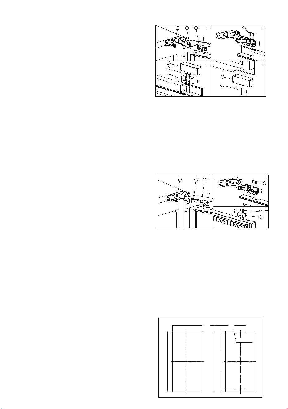
DESIGN 2 – For articulated hinge models
1. Pull the top decoration cover (3) upward and
remove it. Remove the cover caps (2) and then
remove the door by unscrewing the four screws
(1). Be careful to hold the door firmly after
2. removing the screws and place it on a padded
surface to avoid the risk of damage. Leave the
hinges open. (Figure 1)
3. Unscrew the four screws (4) to remove the top
and bottom articulated hinges. (Figure 2)
4. Pop out the cover caps on the left side of the
cabinet and use them to cover the screw holes
on the right-hand side.
5. Pull the top decoration cover (5) upward and remove it. Unscrew the two screws (6) and transfer the
retaining bracket (7) to the opposite side of the door. Refit the top decoration cover (5). (Figure 3)
6. Unscrew the screw (9) and transfer the bottom decoration cover (8) to the opposite side of the door.
(Figure 4)
7. Refit the articulated hinges to the opposite side of the door by using the four screws (3). (Repeat
step 2 in reverse.)
8. Refit the door to the opposite side. Then screw and tighten it after the door is leveled. (Repeat step 1
in reverse.)
DESIGN 3 – For panel ready models
1. Pull the top decoration cover (3) upward and
remove it. Remove the cover caps (2) and then
remove the door by unscrewing the four screws
(1). Be careful to hold the door firmly after
removing the screws and place it on a padded
surface to avoid the risk of damage. Leave the
hinges open. (Figure 1)
2. Unscrew the four screws (4) to remove the top
and bottom articulated hinges. (Figure 2)
3. Pop out the cover caps on the left side of the cabinet and use them to cover the screw holes on the
right-hand side.
4. Unscrew the two screws (5) and transfer the retaining bracket (6) to the opposite side of the door.
(Figure 3)
5. Refit the articulated hinges to the opposite side of the door by using the four screws (3). (Repeat
step 2 in reverse.)
6. Refit the door to the opposite side. Then screw and tighten it after the door is leveled. (Repeat step 1
in reverse.)
7. Refit the alternative top decoration cover included in the fittings on the top of door.
OVERLAY PANEL INSTALLATION INSTRUCTION
Door Panel Preparation
Depending on the model prepare the overlay panel to
the dimensions shown below. Then attach the handle
to the overlay panel by using the flat head screws and
drive the screws flush with the panel if needed.
NOTE:
H can be 28⅜" and 30". It depends on the actual product specification.
Weight of the overlay panel should not exceed 22 Lbs.
It is important to ensure that all drilled holes are drilled to the correct depth in order to
avoid splits in the wood when hardware is installed.
Drill the handle installation holes in the overlay panel according to the handle you are
planning to use. If reusing the handles came with the unit, drill two holes with holes
distance same as handle and diameter 5mm in the overlay panel.
use an extension cord with this appliance. However, if you must use an extension cord it is absolutely
necessary that it be a UL/CUL-listed, 3-wire grounding type appliance extension cord having a grounding
type plug and outlet and that the electrical rating of the cord be 115 volts and at least 10 amperes.
INSTALLING THE HANDLE
IMPORTANT: Do not overtighten the screws & do not use
power tools to install the handle.
DESIGN 1 –
Locate the handle (2) over the mounting stubs (1) of the
door and tighten the grub screws (3) with an Allen key to
secure the handle.
DESIGN 2 –
Remove the door gasket on the side you wish to install the
handle - you can see two designated holes for handle
installation.
Install the handle (3) tightly as shown above with two
screws (1) and flat washers (2) provided.
Replace the door gasket.
REVERSING THE DOOR HINGE
It is possible to reverse the door on this appliance, if
required.
To do so, follow the steps below:
Note: All parts removed must be saved to do the reinstallation of the door.
DESIGN 1 – For standard hinge models
1. Remove the bottom hinge (1) by unscrewing the
two lock screws (2). Be careful to hold the door
firmly after removing the screws. (Fig. 1)
2. Gently pull down to remove the door (3) from the
right top hinge and place it on a padded surface
to avoid the risk of damage. Then remove the
right top hinge (3). (Fig. 2 & 3)
3. Pop out the cover caps on the left side of cabinet
and use them to cover the screw holes on the
right hand side.
4. Screw the alternative left top hinge (4), included
in the fittings, on the left hand side of cabinet.
(Fig. 3)
5. Relocate the door to the designated position. Then screw the bottom hinge assembly on the left
designated position and tighten it after the door is leveled.
NOTE: Make sure that the socket and ON/OFF switch are easily accessible after the appliance has been
installed.
BUILT-UNDER INSTRUCTIONS
Make sure your installation does not block the front ventilation grill. If the unit is fully integrated to be
installed for fitting kitchen, make sure that the ventilation gaps in the plinth are at least 300 square
centimeters and remove the ventilation grilles, so that warm air can disperse unhindered. Otherwise the
appliance has to work harder, resulting in an increase in electricity consumption.
NOTE: When pushing the appliance into the niche, make sure that the mains cable does not get trapped.
CAUTION
To ensure the proper functioning of the appliance, air vents should never be blocked or covered.
ELECTRICAL CONNECTION
Check that the voltage marked on the product corresponds with your supply voltage
WARNING
Improper use of the grounded plug can result in the risk of electrical shock. If the power cord is damaged,
have it replaced by a qualified electrician or an authorized service center.
This appliance should be properly grounded for your safety. The power cord of this appliance is equipped
with a three-prong plug which mates with standard three-prong wall outlets to minimize the possibility of
electrical shock.
Do not under any circumstances cut or remove the third (ground) prong from the power cord supplied.
For personal safety, this appliance must be properly grounded.
This appliance requires a standard 115/120 Volt AC ~ 60Hz three-prong grounded electrical outlet. Have
the wall outlet and circuit checked by a qualified electrician to make sure the outlet is properly grounded.
When a standard 2-prong wall outlet is encountered, it is your responsibility and obligation to have it
replaced with a properly grounded 3-prong wall outlet.
To prevent accidental injury, the cord should be secured behind the appliance and not left exposed or
dangling.
The appliance should always be plugged into its own individual electrical outlet which has a voltage
rating that matches the rating label on the appliance. This provides the best performance and also
prevents overloading house wiring circuits that could cause a fire hazard from overheating. Never unplug
the appliance by pulling on the power cord. Always grip the plug firmly and pull straight out from the
receptacle. Repair or replace immediately all power cords that have become frayed or otherwise
damaged. Do not use a cord that shows cracks or abrasion damage along its length or at either end.
When moving the appliance, be careful not to damage the power cord.
EXTENSION CORD
Because of potential safety hazards under certain conditions, it is strongly recommended that you do not
1 2
1 2
3
4
4
5
6
7
8
9
3
1 2
1 2
4
3
3
5
6
H
14 3/4"
REAR VIEW
3/4" 5 29/32"
29/32"29/32"
3/32" ,
5/16" Deep
BEFORE USING YOUR APPLIANCE
- Remove all exterior and interior packing. Clean the interior surface with lukewarm water using a soft
cloth. The unit may have residual odors at first, they will disappear as the unit cools.
- IMPORTANT: Before connecting the icemachine to the power source, let it stand upright for
approximately 24 hours. This will reduce the possibility of a malfunction in the cooling system
caused by handling during transportation.
- The door on this appliance can be opened either the left or the right side. The unit is delivered with
the door opening on the left side. Should you wish to open the door from the right, follow the
instructions "Reversing the door hinge".
- Install the handle on the door.
- Sanitize the ice machine. All ice machines are factory-operated and adjusted before shipment.
Normally, new installations do not require any adjustment.
INSTALLATION OF YOUR APPLIANCE
WARNING
This appliance must be installed in accordance with all local codes and ordinances.
• The appliances are designed to be built-in or recessed or free-standing installation.
• This ice machine should be properly installed by qualified personnel.
• WARNING: Flammable Refrigerant Used. Appliance should be installed in accordance with the
Safety Standard for Refrigeration Systems, ANSI/ASHRAE 15.
• Place your ice machine on a floor that is even and strong enough to support it when it is fully loaded.
It is very important for the ice machine to be level in order to work properly. To level your unit, adjust
the front adjustable legs at the bottom of the unit.
• For freestanding installation, 5 inches (127mm) of space between the back and sides of the unit are
suggested, which allows the proper air circulation to cool the compressor and condenser for energy
saving. Even for built-in installation, it is a must to keep ¾" (5mm) space on each side and at the top
to ensure proper service access and efficient ventilation. Take care that the air vent at the front of
the appliance must never be covered or blocked in any way.
• Installation of the ice maker requires a cold water supply inlet of ¼-in. (6.35mm) soft copper tubing
with a shut-off valve.
• Locate the unit away from direct sunlight and sources of heat (stove, heater, radiator, etc.). Direct
sunlight may affect the acrylic coating and heat sources may increase electrical consumption.
Extreme cold ambient temperatures may also cause the unit not to perform properly.
• Avoid locating the unit in damp areas.
• Plug the unit into an exclusive, easily accessible and properly grounded wall outlet. Do not under any
circumstances cut or remove the third (ground) prong from the power cord. Any questions concern-
ing power and/or earthing should be directed towards a qualified electrician or an authorized
products service centre.
• The appliance must be installed to all electrical, plumbing, water and drain connections in
accordance with state and local codes.
• The equipment must be installed with adequate backflow protection to comply with applicable
federal, state and local codes.
• It is strongly recommended that a water filter be used. A filter, if it is of the proper type, can remove
taste and odors as well as particles. Some water is very hard, and softened water may result in
white, mushy cubes that stick together. Deionized water is not recommended.
Door Panel Installation
Attach the wood overlay panel (1) on the door (2) by using the four wood screws ST4x15 Type AB Philips
(3).
WATER SUPPLY AND DRAIN REQUIREMENTS
Prepare water supply line and drain before installation of your ice machine. Installation requires a 1/4" ID
copper cold water line and compression fitting (not supplied).
The ice machine IM50 is supplied with an automatic drain pump system. The ice machine IM30 is
supplied with a drain hose for gravity draining. Both drain methods require routing to an open site drain.
Do not connect directly to drain line as bacteria from drain line may contaminate the ice machine.
Make certain the hoses are not pinched or kinked or damaged during installation.
Check for leaks after connection.
WATER INLET LINES
CAUTION
Copper tubing is recommended for the water supply line. Water supply tubing made of 1/4" plastic is not
recommended since it greatly increases the potential for water leaks. Manufacturer will not be responsible
for any damage if plastic tubing is used for the supply line.
Follow these guidelines to install water inlet lines:
▪ Do not connect the ice machine to a hot water supply. Be sure all hot water restrictors installed for
other equipment are working. (Check valves on sink faucets, dishwashers, etc.)
▪ If water pressure exceeds the maximum recommended pressure (80 psi - 55 bar), obtain a water
pressure regulator.
▪ Install a water shut-off valve for the ice making water lines.
▪ Insulate the water inlet line to prevent condensation.
▪ Install tubing only in areas where temperatures will remain above freezing.
▪ Leave a coil of copper tubing to allow the ice maker to be pulled out of the cabinet or away from the
wall for service.
DRAIN CONNECTIONS (FACTORY SUPPLIED)
Follow these guidelines when installing drain lines to prevent drain water from flowing back into the ice
machine and storage bin:
▪ Drain lines must have a 1.5 inch drop per 5 feet of run (2.5 cm per meter), and must not create traps.
▪ The floor drain must be large enough to accommodate drainage from all drains.
▪ Drain pump discharge line must terminate at an open site drain.
▪ The maximum length of drain hose is 5 feet (1.5
m).
▪ The maximum rise of drain hose is 2.6 feet (0.8
m).
▪ Pour 3000ml of water into the ice storage bin to
check for leaks in the drainage system.
WATER SUPPLY AND DRAIN LINE
SIZING/CONNECTIONS
CAUTION
Plumbing must conform to state and local codes.
NOTE: If air temperature is less than 60°F (15.5°C), water
temperature must be equal to or greater than 50°F (10°C).
INSTALLATION PROCEDURE
1. Prepare the site by following the instructions under Electrical Connection and Water Supply and
Drain Requirements.
2. Remove ice machine from carton.
3. Inspect for damage.
4. Remove literature packet and drain hose from inside the ice machine.
5. Adjust leg levelers.
6. Reverse door if desired. See Reversing the Door Hinge.
7. Install drain hose to drain on back of ice machine and route to open site drain.
8. Use compression fitting to connect the Water Inlet on back of ice machine to the prepared 1/4" ID
cold water line.
9. Open the shut-off valve on the water line.
10. Connect electrical plug to grounded (three-prong), polarized outlet.
11. Place ice machine back in position and check leveling again. Make any necessary adjustments.
12. Prepare sanitizer solution and sanitize the ice machine according to Cleaning/Sanitizing the Ice
Making System.
13. At initial start-up, ice machine will need approximately 45 minutes to freeze.
INSTALLATION CHECK LIST
▪ Is the Ice Machine level?!
▪ Has all of the packing been removed?
▪ Have all of the electrical and water connections been made?
▪ Has the supply voltage been tested and checked against the rating on the nameplate?
▪ Is there proper clearance around the ice machine for air circulation?
▪ Has the ice machine been installed where ambient temperatures will remain in the range of 41° -
100°F (5° - 38°C)?
▪ Has the ice machine been installed where the incoming water temperature will remain in the range
of 41° - 90°F (5° - 32°C)?
▪ Has the water supply pressure been checked to ensure a minimum of 20 psig with a static pressure
not to exceed 80 psig?
▪ Is the ice machine drain line routed to an open site drain?
▪ Are all electrical leads free from contact with refrigeration lines and moving equipment?
▪ Has the ice machine and bin been sanitized?
▪ Is the ice machine plugged into a properly grounded, polarized receptacle?
▪ Have the water and drain connections been examined for leaks?
10

DESIGN 2 – For articulated hinge models
1. Pull the top decoration cover (3) upward and
remove it. Remove the cover caps (2) and then
remove the door by unscrewing the four screws
(1). Be careful to hold the door firmly after
2. removing the screws and place it on a padded
surface to avoid the risk of damage. Leave the
hinges open. (Figure 1)
3. Unscrew the four screws (4) to remove the top
and bottom articulated hinges. (Figure 2)
4. Pop out the cover caps on the left side of the
cabinet and use them to cover the screw holes
on the right-hand side.
5. Pull the top decoration cover (5) upward and remove it. Unscrew the two screws (6) and transfer the
retaining bracket (7) to the opposite side of the door. Refit the top decoration cover (5). (Figure 3)
6. Unscrew the screw (9) and transfer the bottom decoration cover (8) to the opposite side of the door.
(Figure 4)
7. Refit the articulated hinges to the opposite side of the door by using the four screws (3). (Repeat
step 2 in reverse.)
8. Refit the door to the opposite side. Then screw and tighten it after the door is leveled. (Repeat step 1
in reverse.)
DESIGN 3 – For panel ready models
1. Pull the top decoration cover (3) upward and
remove it. Remove the cover caps (2) and then
remove the door by unscrewing the four screws
(1). Be careful to hold the door firmly after
removing the screws and place it on a padded
surface to avoid the risk of damage. Leave the
hinges open. (Figure 1)
2. Unscrew the four screws (4) to remove the top
and bottom articulated hinges. (Figure 2)
3. Pop out the cover caps on the left side of the cabinet and use them to cover the screw holes on the
right-hand side.
4. Unscrew the two screws (5) and transfer the retaining bracket (6) to the opposite side of the door.
(Figure 3)
5. Refit the articulated hinges to the opposite side of the door by using the four screws (3). (Repeat
step 2 in reverse.)
6. Refit the door to the opposite side. Then screw and tighten it after the door is leveled. (Repeat step 1
in reverse.)
7. Refit the alternative top decoration cover included in the fittings on the top of door.
OVERLAY PANEL INSTALLATION INSTRUCTION
Door Panel Preparation
Depending on the model prepare the overlay panel to
the dimensions shown below. Then attach the handle
to the overlay panel by using the flat head screws and
drive the screws flush with the panel if needed.
NOTE:
H can be 28⅜" and 30". It depends on the actual product specification.
Weight of the overlay panel should not exceed 22 Lbs.
It is important to ensure that all drilled holes are drilled to the correct depth in order to
avoid splits in the wood when hardware is installed.
Drill the handle installation holes in the overlay panel according to the handle you are
planning to use. If reusing the handles came with the unit, drill two holes with holes
distance same as handle and diameter 5mm in the overlay panel.
use an extension cord with this appliance. However, if you must use an extension cord it is absolutely
necessary that it be a UL/CUL-listed, 3-wire grounding type appliance extension cord having a grounding
type plug and outlet and that the electrical rating of the cord be 115 volts and at least 10 amperes.
INSTALLING THE HANDLE
IMPORTANT: Do not overtighten the screws & do not use
power tools to install the handle.
DESIGN 1 –
Locate the handle (2) over the mounting stubs (1) of the
door and tighten the grub screws (3) with an Allen key to
secure the handle.
DESIGN 2 –
Remove the door gasket on the side you wish to install the
handle - you can see two designated holes for handle
installation.
Install the handle (3) tightly as shown above with two
screws (1) and flat washers (2) provided.
Replace the door gasket.
REVERSING THE DOOR HINGE
It is possible to reverse the door on this appliance, if
required.
To do so, follow the steps below:
Note: All parts removed must be saved to do the reinstallation of the door.
DESIGN 1 – For standard hinge models
1. Remove the bottom hinge (1) by unscrewing the
two lock screws (2). Be careful to hold the door
firmly after removing the screws. (Fig. 1)
2. Gently pull down to remove the door (3) from the
right top hinge and place it on a padded surface
to avoid the risk of damage. Then remove the
right top hinge (3). (Fig. 2 & 3)
3. Pop out the cover caps on the left side of cabinet
and use them to cover the screw holes on the
right hand side.
4. Screw the alternative left top hinge (4), included
in the fittings, on the left hand side of cabinet.
(Fig. 3)
5. Relocate the door to the designated position. Then screw the bottom hinge assembly on the left
designated position and tighten it after the door is leveled.
NOTE: Make sure that the socket and ON/OFF switch are easily accessible after the appliance has been
installed.
BUILT-UNDER INSTRUCTIONS
Make sure your installation does not block the front ventilation grill. If the unit is fully integrated to be
installed for fitting kitchen, make sure that the ventilation gaps in the plinth are at least 300 square
centimeters and remove the ventilation grilles, so that warm air can disperse unhindered. Otherwise the
appliance has to work harder, resulting in an increase in electricity consumption.
NOTE: When pushing the appliance into the niche, make sure that the mains cable does not get trapped.
CAUTION
To ensure the proper functioning of the appliance, air vents should never be blocked or covered.
ELECTRICAL CONNECTION
Check that the voltage marked on the product corresponds with your supply voltage
WARNING
Improper use of the grounded plug can result in the risk of electrical shock. If the power cord is damaged,
have it replaced by a qualified electrician or an authorized service center.
This appliance should be properly grounded for your safety. The power cord of this appliance is equipped
with a three-prong plug which mates with standard three-prong wall outlets to minimize the possibility of
electrical shock.
Do not under any circumstances cut or remove the third (ground) prong from the power cord supplied.
For personal safety, this appliance must be properly grounded.
This appliance requires a standard 115/120 Volt AC ~ 60Hz three-prong grounded electrical outlet. Have
the wall outlet and circuit checked by a qualified electrician to make sure the outlet is properly grounded.
When a standard 2-prong wall outlet is encountered, it is your responsibility and obligation to have it
replaced with a properly grounded 3-prong wall outlet.
To prevent accidental injury, the cord should be secured behind the appliance and not left exposed or
dangling.
The appliance should always be plugged into its own individual electrical outlet which has a voltage
rating that matches the rating label on the appliance. This provides the best performance and also
prevents overloading house wiring circuits that could cause a fire hazard from overheating. Never unplug
the appliance by pulling on the power cord. Always grip the plug firmly and pull straight out from the
receptacle. Repair or replace immediately all power cords that have become frayed or otherwise
damaged. Do not use a cord that shows cracks or abrasion damage along its length or at either end.
When moving the appliance, be careful not to damage the power cord.
EXTENSION CORD
Because of potential safety hazards under certain conditions, it is strongly recommended that you do not
Location Water
Temperature
Water
Pressure
Ice Making
Water Inlet
41°F(5°C)
Min.
90°F(32°C)
Max.
20 psig (138
kPA) Min.
80 psig (552
kPA) Max.
Location Ice Machine
Fitting
Tubing Size
Up to Ice
Machine
Fitting
Ice Making 1/4” (.64 cm) 1/4" (.64 cm)
Water Inlet ID Copper
Tubing
minimum
inside
diameter
BEFORE USING YOUR APPLIANCE
- Remove all exterior and interior packing. Clean the interior surface with lukewarm water using a soft
cloth. The unit may have residual odors at first, they will disappear as the unit cools.
- IMPORTANT: Before connecting the icemachine to the power source, let it stand upright for
approximately 24 hours. This will reduce the possibility of a malfunction in the cooling system
caused by handling during transportation.
- The door on this appliance can be opened either the left or the right side. The unit is delivered with
the door opening on the left side. Should you wish to open the door from the right, follow the
instructions "Reversing the door hinge".
- Install the handle on the door.
- Sanitize the ice machine. All ice machines are factory-operated and adjusted before shipment.
Normally, new installations do not require any adjustment.
INSTALLATION OF YOUR APPLIANCE
WARNING
This appliance must be installed in accordance with all local codes and ordinances.
• The appliances are designed to be built-in or recessed or free-standing installation.
• This ice machine should be properly installed by qualified personnel.
• WARNING: Flammable Refrigerant Used. Appliance should be installed in accordance with the
Safety Standard for Refrigeration Systems, ANSI/ASHRAE 15.
• Place your ice machine on a floor that is even and strong enough to support it when it is fully loaded.
It is very important for the ice machine to be level in order to work properly. To level your unit, adjust
the front adjustable legs at the bottom of the unit.
• For freestanding installation, 5 inches (127mm) of space between the back and sides of the unit are
suggested, which allows the proper air circulation to cool the compressor and condenser for energy
saving. Even for built-in installation, it is a must to keep ¾" (5mm) space on each side and at the top
to ensure proper service access and efficient ventilation. Take care that the air vent at the front of
the appliance must never be covered or blocked in any way.
• Installation of the ice maker requires a cold water supply inlet of ¼-in. (6.35mm) soft copper tubing
with a shut-off valve.
• Locate the unit away from direct sunlight and sources of heat (stove, heater, radiator, etc.). Direct
sunlight may affect the acrylic coating and heat sources may increase electrical consumption.
Extreme cold ambient temperatures may also cause the unit not to perform properly.
• Avoid locating the unit in damp areas.
• Plug the unit into an exclusive, easily accessible and properly grounded wall outlet. Do not under any
circumstances cut or remove the third (ground) prong from the power cord. Any questions concern-
ing power and/or earthing should be directed towards a qualified electrician or an authorized
products service centre.
• The appliance must be installed to all electrical, plumbing, water and drain connections in
accordance with state and local codes.
• The equipment must be installed with adequate backflow protection to comply with applicable
federal, state and local codes.
• It is strongly recommended that a water filter be used. A filter, if it is of the proper type, can remove
taste and odors as well as particles. Some water is very hard, and softened water may result in
white, mushy cubes that stick together. Deionized water is not recommended.
Door Panel Installation
Attach the wood overlay panel (1) on the door (2) by using the four wood screws ST4x15 Type AB Philips
(3).
WATER SUPPLY AND DRAIN REQUIREMENTS
Prepare water supply line and drain before installation of your ice machine. Installation requires a 1/4" ID
copper cold water line and compression fitting (not supplied).
The ice machine IM50 is supplied with an automatic drain pump system. The ice machine IM30 is
supplied with a drain hose for gravity draining. Both drain methods require routing to an open site drain.
Do not connect directly to drain line as bacteria from drain line may contaminate the ice machine.
Make certain the hoses are not pinched or kinked or damaged during installation.
Check for leaks after connection.
WATER INLET LINES
CAUTION
Copper tubing is recommended for the water supply line. Water supply tubing made of 1/4" plastic is not
recommended since it greatly increases the potential for water leaks. Manufacturer will not be responsible
for any damage if plastic tubing is used for the supply line.
Follow these guidelines to install water inlet lines:
▪ Do not connect the ice machine to a hot water supply. Be sure all hot water restrictors installed for
other equipment are working. (Check valves on sink faucets, dishwashers, etc.)
▪ If water pressure exceeds the maximum recommended pressure (80 psi - 55 bar), obtain a water
pressure regulator.
▪ Install a water shut-off valve for the ice making water lines.
▪ Insulate the water inlet line to prevent condensation.
▪ Install tubing only in areas where temperatures will remain above freezing.
▪ Leave a coil of copper tubing to allow the ice maker to be pulled out of the cabinet or away from the
wall for service.
DRAIN CONNECTIONS (FACTORY SUPPLIED)
Follow these guidelines when installing drain lines to prevent drain water from flowing back into the ice
machine and storage bin:
▪ Drain lines must have a 1.5 inch drop per 5 feet of run (2.5 cm per meter), and must not create traps.
▪ The floor drain must be large enough to accommodate drainage from all drains.
▪ Drain pump discharge line must terminate at an open site drain.
▪ The maximum length of drain hose is 5 feet (1.5
m).
▪ The maximum rise of drain hose is 2.6 feet (0.8
m).
▪ Pour 3000ml of water into the ice storage bin to
check for leaks in the drainage system.
WATER SUPPLY AND DRAIN LINE
SIZING/CONNECTIONS
CAUTION
Plumbing must conform to state and local codes.
NOTE: If air temperature is less than 60°F (15.5°C), water
temperature must be equal to or greater than 50°F (10°C).
INSTALLATION PROCEDURE
1. Prepare the site by following the instructions under Electrical Connection and Water Supply and
Drain Requirements.
2. Remove ice machine from carton.
3. Inspect for damage.
4. Remove literature packet and drain hose from inside the ice machine.
5. Adjust leg levelers.
6. Reverse door if desired. See Reversing the Door Hinge.
7. Install drain hose to drain on back of ice machine and route to open site drain.
8. Use compression fitting to connect the Water Inlet on back of ice machine to the prepared 1/4" ID
cold water line.
9. Open the shut-off valve on the water line.
10. Connect electrical plug to grounded (three-prong), polarized outlet.
11. Place ice machine back in position and check leveling again. Make any necessary adjustments.
12. Prepare sanitizer solution and sanitize the ice machine according to Cleaning/Sanitizing the Ice
Making System.
13. At initial start-up, ice machine will need approximately 45 minutes to freeze.
INSTALLATION CHECK LIST
▪ Is the Ice Machine level?!
▪ Has all of the packing been removed?
▪ Have all of the electrical and water connections been made?
▪ Has the supply voltage been tested and checked against the rating on the nameplate?
▪ Is there proper clearance around the ice machine for air circulation?
▪ Has the ice machine been installed where ambient temperatures will remain in the range of 41° -
100°F (5° - 38°C)?
▪ Has the ice machine been installed where the incoming water temperature will remain in the range
of 41° - 90°F (5° - 32°C)?
▪ Has the water supply pressure been checked to ensure a minimum of 20 psig with a static pressure
not to exceed 80 psig?
▪ Is the ice machine drain line routed to an open site drain?
▪ Are all electrical leads free from contact with refrigeration lines and moving equipment?
▪ Has the ice machine and bin been sanitized?
▪ Is the ice machine plugged into a properly grounded, polarized receptacle?
▪ Have the water and drain connections been examined for leaks?
11

DESIGN 2 – For articulated hinge models
1. Pull the top decoration cover (3) upward and
remove it. Remove the cover caps (2) and then
remove the door by unscrewing the four screws
(1). Be careful to hold the door firmly after
2. removing the screws and place it on a padded
surface to avoid the risk of damage. Leave the
hinges open. (Figure 1)
3. Unscrew the four screws (4) to remove the top
and bottom articulated hinges. (Figure 2)
4. Pop out the cover caps on the left side of the
cabinet and use them to cover the screw holes
on the right-hand side.
5. Pull the top decoration cover (5) upward and remove it. Unscrew the two screws (6) and transfer the
retaining bracket (7) to the opposite side of the door. Refit the top decoration cover (5). (Figure 3)
6. Unscrew the screw (9) and transfer the bottom decoration cover (8) to the opposite side of the door.
(Figure 4)
7. Refit the articulated hinges to the opposite side of the door by using the four screws (3). (Repeat
step 2 in reverse.)
8. Refit the door to the opposite side. Then screw and tighten it after the door is leveled. (Repeat step 1
in reverse.)
DESIGN 3 – For panel ready models
1. Pull the top decoration cover (3) upward and
remove it. Remove the cover caps (2) and then
remove the door by unscrewing the four screws
(1). Be careful to hold the door firmly after
removing the screws and place it on a padded
surface to avoid the risk of damage. Leave the
hinges open. (Figure 1)
2. Unscrew the four screws (4) to remove the top
and bottom articulated hinges. (Figure 2)
3. Pop out the cover caps on the left side of the cabinet and use them to cover the screw holes on the
right-hand side.
4. Unscrew the two screws (5) and transfer the retaining bracket (6) to the opposite side of the door.
(Figure 3)
5. Refit the articulated hinges to the opposite side of the door by using the four screws (3). (Repeat
step 2 in reverse.)
6. Refit the door to the opposite side. Then screw and tighten it after the door is leveled. (Repeat step 1
in reverse.)
7. Refit the alternative top decoration cover included in the fittings on the top of door.
OVERLAY PANEL INSTALLATION INSTRUCTION
Door Panel Preparation
Depending on the model prepare the overlay panel to
the dimensions shown below. Then attach the handle
to the overlay panel by using the flat head screws and
drive the screws flush with the panel if needed.
NOTE:
H can be 28⅜" and 30". It depends on the actual product specification.
Weight of the overlay panel should not exceed 22 Lbs.
It is important to ensure that all drilled holes are drilled to the correct depth in order to
avoid splits in the wood when hardware is installed.
Drill the handle installation holes in the overlay panel according to the handle you are
planning to use. If reusing the handles came with the unit, drill two holes with holes
distance same as handle and diameter 5mm in the overlay panel.
use an extension cord with this appliance. However, if you must use an extension cord it is absolutely
necessary that it be a UL/CUL-listed, 3-wire grounding type appliance extension cord having a grounding
type plug and outlet and that the electrical rating of the cord be 115 volts and at least 10 amperes.
INSTALLING THE HANDLE
IMPORTANT: Do not overtighten the screws & do not use
power tools to install the handle.
DESIGN 1 –
Locate the handle (2) over the mounting stubs (1) of the
door and tighten the grub screws (3) with an Allen key to
secure the handle.
DESIGN 2 –
Remove the door gasket on the side you wish to install the
handle - you can see two designated holes for handle
installation.
Install the handle (3) tightly as shown above with two
screws (1) and flat washers (2) provided.
Replace the door gasket.
REVERSING THE DOOR HINGE
It is possible to reverse the door on this appliance, if
required.
To do so, follow the steps below:
Note: All parts removed must be saved to do the reinstallation of the door.
DESIGN 1 – For standard hinge models
1. Remove the bottom hinge (1) by unscrewing the
two lock screws (2). Be careful to hold the door
firmly after removing the screws. (Fig. 1)
2. Gently pull down to remove the door (3) from the
right top hinge and place it on a padded surface
to avoid the risk of damage. Then remove the
right top hinge (3). (Fig. 2 & 3)
3. Pop out the cover caps on the left side of cabinet
and use them to cover the screw holes on the
right hand side.
4. Screw the alternative left top hinge (4), included
in the fittings, on the left hand side of cabinet.
(Fig. 3)
5. Relocate the door to the designated position. Then screw the bottom hinge assembly on the left
designated position and tighten it after the door is leveled.
NOTE: Make sure that the socket and ON/OFF switch are easily accessible after the appliance has been
installed.
BUILT-UNDER INSTRUCTIONS
Make sure your installation does not block the front ventilation grill. If the unit is fully integrated to be
installed for fitting kitchen, make sure that the ventilation gaps in the plinth are at least 300 square
centimeters and remove the ventilation grilles, so that warm air can disperse unhindered. Otherwise the
appliance has to work harder, resulting in an increase in electricity consumption.
NOTE: When pushing the appliance into the niche, make sure that the mains cable does not get trapped.
CAUTION
To ensure the proper functioning of the appliance, air vents should never be blocked or covered.
ELECTRICAL CONNECTION
Check that the voltage marked on the product corresponds with your supply voltage
WARNING
Improper use of the grounded plug can result in the risk of electrical shock. If the power cord is damaged,
have it replaced by a qualified electrician or an authorized service center.
This appliance should be properly grounded for your safety. The power cord of this appliance is equipped
with a three-prong plug which mates with standard three-prong wall outlets to minimize the possibility of
electrical shock.
Do not under any circumstances cut or remove the third (ground) prong from the power cord supplied.
For personal safety, this appliance must be properly grounded.
This appliance requires a standard 115/120 Volt AC ~ 60Hz three-prong grounded electrical outlet. Have
the wall outlet and circuit checked by a qualified electrician to make sure the outlet is properly grounded.
When a standard 2-prong wall outlet is encountered, it is your responsibility and obligation to have it
replaced with a properly grounded 3-prong wall outlet.
To prevent accidental injury, the cord should be secured behind the appliance and not left exposed or
dangling.
The appliance should always be plugged into its own individual electrical outlet which has a voltage
rating that matches the rating label on the appliance. This provides the best performance and also
prevents overloading house wiring circuits that could cause a fire hazard from overheating. Never unplug
the appliance by pulling on the power cord. Always grip the plug firmly and pull straight out from the
receptacle. Repair or replace immediately all power cords that have become frayed or otherwise
damaged. Do not use a cord that shows cracks or abrasion damage along its length or at either end.
When moving the appliance, be careful not to damage the power cord.
EXTENSION CORD
Because of potential safety hazards under certain conditions, it is strongly recommended that you do not
BEFORE USING YOUR APPLIANCE
- Remove all exterior and interior packing. Clean the interior surface with lukewarm water using a soft
cloth. The unit may have residual odors at first, they will disappear as the unit cools.
- IMPORTANT: Before connecting the icemachine to the power source, let it stand upright for
approximately 24 hours. This will reduce the possibility of a malfunction in the cooling system
caused by handling during transportation.
- The door on this appliance can be opened either the left or the right side. The unit is delivered with
the door opening on the left side. Should you wish to open the door from the right, follow the
instructions "Reversing the door hinge".
- Install the handle on the door.
- Sanitize the ice machine. All ice machines are factory-operated and adjusted before shipment.
Normally, new installations do not require any adjustment.
INSTALLATION OF YOUR APPLIANCE
WARNING
This appliance must be installed in accordance with all local codes and ordinances.
• The appliances are designed to be built-in or recessed or free-standing installation.
• This ice machine should be properly installed by qualified personnel.
• WARNING: Flammable Refrigerant Used. Appliance should be installed in accordance with the
Safety Standard for Refrigeration Systems, ANSI/ASHRAE 15.
• Place your ice machine on a floor that is even and strong enough to support it when it is fully loaded.
It is very important for the ice machine to be level in order to work properly. To level your unit, adjust
the front adjustable legs at the bottom of the unit.
• For freestanding installation, 5 inches (127mm) of space between the back and sides of the unit are
suggested, which allows the proper air circulation to cool the compressor and condenser for energy
saving. Even for built-in installation, it is a must to keep ¾" (5mm) space on each side and at the top
to ensure proper service access and efficient ventilation. Take care that the air vent at the front of
the appliance must never be covered or blocked in any way.
• Installation of the ice maker requires a cold water supply inlet of ¼-in. (6.35mm) soft copper tubing
with a shut-off valve.
• Locate the unit away from direct sunlight and sources of heat (stove, heater, radiator, etc.). Direct
sunlight may affect the acrylic coating and heat sources may increase electrical consumption.
Extreme cold ambient temperatures may also cause the unit not to perform properly.
• Avoid locating the unit in damp areas.
• Plug the unit into an exclusive, easily accessible and properly grounded wall outlet. Do not under any
circumstances cut or remove the third (ground) prong from the power cord. Any questions concern-
ing power and/or earthing should be directed towards a qualified electrician or an authorized
products service centre.
• The appliance must be installed to all electrical, plumbing, water and drain connections in
accordance with state and local codes.
• The equipment must be installed with adequate backflow protection to comply with applicable
federal, state and local codes.
• It is strongly recommended that a water filter be used. A filter, if it is of the proper type, can remove
taste and odors as well as particles. Some water is very hard, and softened water may result in
white, mushy cubes that stick together. Deionized water is not recommended.
Door Panel Installation
Attach the wood overlay panel (1) on the door (2) by using the four wood screws ST4x15 Type AB Philips
(3).
WATER SUPPLY AND DRAIN REQUIREMENTS
Prepare water supply line and drain before installation of your ice machine. Installation requires a 1/4" ID
copper cold water line and compression fitting (not supplied).
The ice machine IM50 is supplied with an automatic drain pump system. The ice machine IM30 is
supplied with a drain hose for gravity draining. Both drain methods require routing to an open site drain.
Do not connect directly to drain line as bacteria from drain line may contaminate the ice machine.
Make certain the hoses are not pinched or kinked or damaged during installation.
Check for leaks after connection.
WATER INLET LINES
CAUTION
Copper tubing is recommended for the water supply line. Water supply tubing made of 1/4" plastic is not
recommended since it greatly increases the potential for water leaks. Manufacturer will not be responsible
for any damage if plastic tubing is used for the supply line.
Follow these guidelines to install water inlet lines:
▪ Do not connect the ice machine to a hot water supply. Be sure all hot water restrictors installed for
other equipment are working. (Check valves on sink faucets, dishwashers, etc.)
▪ If water pressure exceeds the maximum recommended pressure (80 psi - 55 bar), obtain a water
pressure regulator.
▪ Install a water shut-off valve for the ice making water lines.
▪ Insulate the water inlet line to prevent condensation.
▪ Install tubing only in areas where temperatures will remain above freezing.
▪ Leave a coil of copper tubing to allow the ice maker to be pulled out of the cabinet or away from the
wall for service.
DRAIN CONNECTIONS (FACTORY SUPPLIED)
Follow these guidelines when installing drain lines to prevent drain water from flowing back into the ice
machine and storage bin:
▪ Drain lines must have a 1.5 inch drop per 5 feet of run (2.5 cm per meter), and must not create traps.
▪ The floor drain must be large enough to accommodate drainage from all drains.
▪ Drain pump discharge line must terminate at an open site drain.
▪ The maximum length of drain hose is 5 feet (1.5
m).
▪ The maximum rise of drain hose is 2.6 feet (0.8
m).
▪ Pour 3000ml of water into the ice storage bin to
check for leaks in the drainage system.
WATER SUPPLY AND DRAIN LINE
SIZING/CONNECTIONS
CAUTION
Plumbing must conform to state and local codes.
NOTE: If air temperature is less than 60°F (15.5°C), water
temperature must be equal to or greater than 50°F (10°C).
INSTALLATION PROCEDURE
1. Prepare the site by following the instructions under Electrical Connection and Water Supply and
Drain Requirements.
2. Remove ice machine from carton.
3. Inspect for damage.
4. Remove literature packet and drain hose from inside the ice machine.
5. Adjust leg levelers.
6. Reverse door if desired. See Reversing the Door Hinge.
7. Install drain hose to drain on back of ice machine and route to open site drain.
8. Use compression fitting to connect the Water Inlet on back of ice machine to the prepared 1/4" ID
cold water line.
9. Open the shut-off valve on the water line.
10. Connect electrical plug to grounded (three-prong), polarized outlet.
11. Place ice machine back in position and check leveling again. Make any necessary adjustments.
12. Prepare sanitizer solution and sanitize the ice machine according to Cleaning/Sanitizing the Ice
Making System.
13. At initial start-up, ice machine will need approximately 45 minutes to freeze.
INSTALLATION CHECK LIST
▪ Is the Ice Machine level?!
▪ Has all of the packing been removed?
▪ Have all of the electrical and water connections been made?
▪ Has the supply voltage been tested and checked against the rating on the nameplate?
▪ Is there proper clearance around the ice machine for air circulation?
▪ Has the ice machine been installed where ambient temperatures will remain in the range of 41° -
100°F (5° - 38°C)?
▪ Has the ice machine been installed where the incoming water temperature will remain in the range
of 41° - 90°F (5° - 32°C)?
▪ Has the water supply pressure been checked to ensure a minimum of 20 psig with a static pressure
not to exceed 80 psig?
▪ Is the ice machine drain line routed to an open site drain?
▪ Are all electrical leads free from contact with refrigeration lines and moving equipment?
▪ Has the ice machine and bin been sanitized?
▪ Is the ice machine plugged into a properly grounded, polarized receptacle?
▪ Have the water and drain connections been examined for leaks?
12
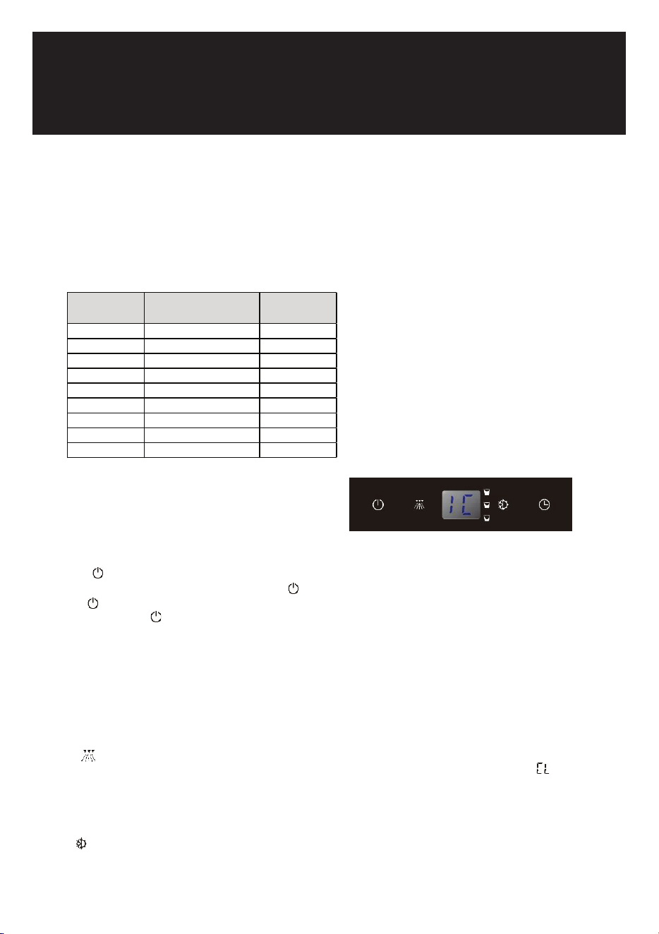
▪ The ice machine is factory-operated and adjusted before shipment. Normally, new installation does
not require any adjustment.
▪ Turn on the water tap, then plug the machine or touch the POWER key to turn on. The ice machine
will start working automatically.
▪ After 3 minutes, the ice machine will automatically go to the freeze cycle, and the sound of water
flowing will be heard.
▪ This appliance is designed for operation at certain ambient temperatures. The climatic class is
specified on the rating plate.
USE AND CONTROL
The Controls of Your Unit
POWER
To turn the appliance off, touch and hold the key for 5 seconds. To turn the appliance on, press and
hold the key for 1 second.
NOTE: Touching the key once can switch off the audible alarm when the alarm is on.
NOTE:
If the unit is unplugged, power lost, or turned off, you must wait 3 to 5 minutes before restarting the unit.
If you attempt to restart before this time delay, the unit will not start.
Although the machine has been tested and cleaned at the factory, due to long-term transit and storage,
the first batch of cubes must be discarded.
Never turn the water supply tap off when the ice machine is working.
Never touch evaporator when unit is running.
CLEAN
In stand-by mode touching the CLEAN key will initiate a clean cycle. The display will show . The
background light of CLEAN key will flash after 180 days of use to indicate it is time to clean the machine.
It will remain flashing until the clean cycle is operated once or touching and holding the CLEAN key for 5
seconds to cancel the clean cycle.
MODE
Touching the MODE key toggles between 2 operation cycles: ice making cycle (default) and harvest
cycle.
DESIGN 2 – For articulated hinge models
1. Pull the top decoration cover (3) upward and
remove it. Remove the cover caps (2) and then
remove the door by unscrewing the four screws
(1). Be careful to hold the door firmly after
2. removing the screws and place it on a padded
surface to avoid the risk of damage. Leave the
hinges open. (Figure 1)
3. Unscrew the four screws (4) to remove the top
and bottom articulated hinges. (Figure 2)
4. Pop out the cover caps on the left side of the
cabinet and use them to cover the screw holes
on the right-hand side.
5. Pull the top decoration cover (5) upward and remove it. Unscrew the two screws (6) and transfer the
retaining bracket (7) to the opposite side of the door. Refit the top decoration cover (5). (Figure 3)
6. Unscrew the screw (9) and transfer the bottom decoration cover (8) to the opposite side of the door.
(Figure 4)
7. Refit the articulated hinges to the opposite side of the door by using the four screws (3). (Repeat
step 2 in reverse.)
8. Refit the door to the opposite side. Then screw and tighten it after the door is leveled. (Repeat step 1
in reverse.)
DESIGN 3 – For panel ready models
1. Pull the top decoration cover (3) upward and
remove it. Remove the cover caps (2) and then
remove the door by unscrewing the four screws
(1). Be careful to hold the door firmly after
removing the screws and place it on a padded
surface to avoid the risk of damage. Leave the
hinges open. (Figure 1)
2. Unscrew the four screws (4) to remove the top
and bottom articulated hinges. (Figure 2)
3. Pop out the cover caps on the left side of the cabinet and use them to cover the screw holes on the
right-hand side.
4. Unscrew the two screws (5) and transfer the retaining bracket (6) to the opposite side of the door.
(Figure 3)
5. Refit the articulated hinges to the opposite side of the door by using the four screws (3). (Repeat
step 2 in reverse.)
6. Refit the door to the opposite side. Then screw and tighten it after the door is leveled. (Repeat step 1
in reverse.)
7. Refit the alternative top decoration cover included in the fittings on the top of door.
OVERLAY PANEL INSTALLATION INSTRUCTION
Door Panel Preparation
Depending on the model prepare the overlay panel to
the dimensions shown below. Then attach the handle
to the overlay panel by using the flat head screws and
drive the screws flush with the panel if needed.
NOTE:
H can be 28⅜" and 30". It depends on the actual product specification.
Weight of the overlay panel should not exceed 22 Lbs.
It is important to ensure that all drilled holes are drilled to the correct depth in order to
avoid splits in the wood when hardware is installed.
Drill the handle installation holes in the overlay panel according to the handle you are
planning to use. If reusing the handles came with the unit, drill two holes with holes
distance same as handle and diameter 5mm in the overlay panel.
use an extension cord with this appliance. However, if you must use an extension cord it is absolutely
necessary that it be a UL/CUL-listed, 3-wire grounding type appliance extension cord having a grounding
type plug and outlet and that the electrical rating of the cord be 115 volts and at least 10 amperes.
INSTALLING THE HANDLE
IMPORTANT: Do not overtighten the screws & do not use
power tools to install the handle.
DESIGN 1 –
Locate the handle (2) over the mounting stubs (1) of the
door and tighten the grub screws (3) with an Allen key to
secure the handle.
DESIGN 2 –
Remove the door gasket on the side you wish to install the
handle - you can see two designated holes for handle
installation.
Install the handle (3) tightly as shown above with two
screws (1) and flat washers (2) provided.
Replace the door gasket.
REVERSING THE DOOR HINGE
It is possible to reverse the door on this appliance, if
required.
To do so, follow the steps below:
Note: All parts removed must be saved to do the reinstallation of the door.
DESIGN 1 – For standard hinge models
1. Remove the bottom hinge (1) by unscrewing the
two lock screws (2). Be careful to hold the door
firmly after removing the screws. (Fig. 1)
2. Gently pull down to remove the door (3) from the
right top hinge and place it on a padded surface
to avoid the risk of damage. Then remove the
right top hinge (3). (Fig. 2 & 3)
3. Pop out the cover caps on the left side of cabinet
and use them to cover the screw holes on the
right hand side.
4. Screw the alternative left top hinge (4), included
in the fittings, on the left hand side of cabinet.
(Fig. 3)
5. Relocate the door to the designated position. Then screw the bottom hinge assembly on the left
designated position and tighten it after the door is leveled.
NOTE: Make sure that the socket and ON/OFF switch are easily accessible after the appliance has been
installed.
BUILT-UNDER INSTRUCTIONS
Make sure your installation does not block the front ventilation grill. If the unit is fully integrated to be
installed for fitting kitchen, make sure that the ventilation gaps in the plinth are at least 300 square
centimeters and remove the ventilation grilles, so that warm air can disperse unhindered. Otherwise the
appliance has to work harder, resulting in an increase in electricity consumption.
NOTE: When pushing the appliance into the niche, make sure that the mains cable does not get trapped.
CAUTION
To ensure the proper functioning of the appliance, air vents should never be blocked or covered.
ELECTRICAL CONNECTION
Check that the voltage marked on the product corresponds with your supply voltage
WARNING
Improper use of the grounded plug can result in the risk of electrical shock. If the power cord is damaged,
have it replaced by a qualified electrician or an authorized service center.
This appliance should be properly grounded for your safety. The power cord of this appliance is equipped
with a three-prong plug which mates with standard three-prong wall outlets to minimize the possibility of
electrical shock.
Do not under any circumstances cut or remove the third (ground) prong from the power cord supplied.
For personal safety, this appliance must be properly grounded.
This appliance requires a standard 115/120 Volt AC ~ 60Hz three-prong grounded electrical outlet. Have
the wall outlet and circuit checked by a qualified electrician to make sure the outlet is properly grounded.
When a standard 2-prong wall outlet is encountered, it is your responsibility and obligation to have it
replaced with a properly grounded 3-prong wall outlet.
To prevent accidental injury, the cord should be secured behind the appliance and not left exposed or
dangling.
The appliance should always be plugged into its own individual electrical outlet which has a voltage
rating that matches the rating label on the appliance. This provides the best performance and also
prevents overloading house wiring circuits that could cause a fire hazard from overheating. Never unplug
the appliance by pulling on the power cord. Always grip the plug firmly and pull straight out from the
receptacle. Repair or replace immediately all power cords that have become frayed or otherwise
damaged. Do not use a cord that shows cracks or abrasion damage along its length or at either end.
When moving the appliance, be careful not to damage the power cord.
EXTENSION CORD
Because of potential safety hazards under certain conditions, it is strongly recommended that you do not
BEFORE USING YOUR APPLIANCE
- Remove all exterior and interior packing. Clean the interior surface with lukewarm water using a soft
cloth. The unit may have residual odors at first, they will disappear as the unit cools.
- IMPORTANT: Before connecting the icemachine to the power source, let it stand upright for
approximately 24 hours. This will reduce the possibility of a malfunction in the cooling system
caused by handling during transportation.
- The door on this appliance can be opened either the left or the right side. The unit is delivered with
the door opening on the left side. Should you wish to open the door from the right, follow the
instructions "Reversing the door hinge".
- Install the handle on the door.
- Sanitize the ice machine. All ice machines are factory-operated and adjusted before shipment.
Normally, new installations do not require any adjustment.
INSTALLATION OF YOUR APPLIANCE
WARNING
This appliance must be installed in accordance with all local codes and ordinances.
• The appliances are designed to be built-in or recessed or free-standing installation.
• This ice machine should be properly installed by qualified personnel.
• WARNING: Flammable Refrigerant Used. Appliance should be installed in accordance with the
Safety Standard for Refrigeration Systems, ANSI/ASHRAE 15.
• Place your ice machine on a floor that is even and strong enough to support it when it is fully loaded.
It is very important for the ice machine to be level in order to work properly. To level your unit, adjust
the front adjustable legs at the bottom of the unit.
• For freestanding installation, 5 inches (127mm) of space between the back and sides of the unit are
suggested, which allows the proper air circulation to cool the compressor and condenser for energy
saving. Even for built-in installation, it is a must to keep ¾" (5mm) space on each side and at the top
to ensure proper service access and efficient ventilation. Take care that the air vent at the front of
the appliance must never be covered or blocked in any way.
• Installation of the ice maker requires a cold water supply inlet of ¼-in. (6.35mm) soft copper tubing
with a shut-off valve.
• Locate the unit away from direct sunlight and sources of heat (stove, heater, radiator, etc.). Direct
sunlight may affect the acrylic coating and heat sources may increase electrical consumption.
Extreme cold ambient temperatures may also cause the unit not to perform properly.
• Avoid locating the unit in damp areas.
• Plug the unit into an exclusive, easily accessible and properly grounded wall outlet. Do not under any
circumstances cut or remove the third (ground) prong from the power cord. Any questions concern-
ing power and/or earthing should be directed towards a qualified electrician or an authorized
products service centre.
• The appliance must be installed to all electrical, plumbing, water and drain connections in
accordance with state and local codes.
• The equipment must be installed with adequate backflow protection to comply with applicable
federal, state and local codes.
• It is strongly recommended that a water filter be used. A filter, if it is of the proper type, can remove
taste and odors as well as particles. Some water is very hard, and softened water may result in
white, mushy cubes that stick together. Deionized water is not recommended.
Door Panel Installation
Attach the wood overlay panel (1) on the door (2) by using the four wood screws ST4x15 Type AB Philips
(3).
WATER SUPPLY AND DRAIN REQUIREMENTS
Prepare water supply line and drain before installation of your ice machine. Installation requires a 1/4" ID
copper cold water line and compression fitting (not supplied).
The ice machine IM50 is supplied with an automatic drain pump system. The ice machine IM30 is
supplied with a drain hose for gravity draining. Both drain methods require routing to an open site drain.
Do not connect directly to drain line as bacteria from drain line may contaminate the ice machine.
Make certain the hoses are not pinched or kinked or damaged during installation.
Check for leaks after connection.
WATER INLET LINES
CAUTION
Copper tubing is recommended for the water supply line. Water supply tubing made of 1/4" plastic is not
recommended since it greatly increases the potential for water leaks. Manufacturer will not be responsible
for any damage if plastic tubing is used for the supply line.
Follow these guidelines to install water inlet lines:
▪ Do not connect the ice machine to a hot water supply. Be sure all hot water restrictors installed for
other equipment are working. (Check valves on sink faucets, dishwashers, etc.)
▪ If water pressure exceeds the maximum recommended pressure (80 psi - 55 bar), obtain a water
pressure regulator.
▪ Install a water shut-off valve for the ice making water lines.
▪ Insulate the water inlet line to prevent condensation.
▪ Install tubing only in areas where temperatures will remain above freezing.
▪ Leave a coil of copper tubing to allow the ice maker to be pulled out of the cabinet or away from the
wall for service.
DRAIN CONNECTIONS (FACTORY SUPPLIED)
Follow these guidelines when installing drain lines to prevent drain water from flowing back into the ice
machine and storage bin:
▪ Drain lines must have a 1.5 inch drop per 5 feet of run (2.5 cm per meter), and must not create traps.
▪ The floor drain must be large enough to accommodate drainage from all drains.
▪ Drain pump discharge line must terminate at an open site drain.
▪ The maximum length of drain hose is 5 feet (1.5
m).
▪ The maximum rise of drain hose is 2.6 feet (0.8
m).
▪ Pour 3000ml of water into the ice storage bin to
check for leaks in the drainage system.
WATER SUPPLY AND DRAIN LINE
SIZING/CONNECTIONS
CAUTION
Plumbing must conform to state and local codes.
NOTE: If air temperature is less than 60°F (15.5°C), water
temperature must be equal to or greater than 50°F (10°C).
INSTALLATION PROCEDURE
1. Prepare the site by following the instructions under Electrical Connection and Water Supply and
Drain Requirements.
2. Remove ice machine from carton.
3. Inspect for damage.
4. Remove literature packet and drain hose from inside the ice machine.
5. Adjust leg levelers.
6. Reverse door if desired. See Reversing the Door Hinge.
7. Install drain hose to drain on back of ice machine and route to open site drain.
8. Use compression fitting to connect the Water Inlet on back of ice machine to the prepared 1/4" ID
cold water line.
9. Open the shut-off valve on the water line.
10. Connect electrical plug to grounded (three-prong), polarized outlet.
11. Place ice machine back in position and check leveling again. Make any necessary adjustments.
12. Prepare sanitizer solution and sanitize the ice machine according to Cleaning/Sanitizing the Ice
Making System.
13. At initial start-up, ice machine will need approximately 45 minutes to freeze.
INSTALLATION CHECK LIST
▪ Is the Ice Machine level?!
▪ Has all of the packing been removed?
▪ Have all of the electrical and water connections been made?
▪ Has the supply voltage been tested and checked against the rating on the nameplate?
▪ Is there proper clearance around the ice machine for air circulation?
▪ Has the ice machine been installed where ambient temperatures will remain in the range of 41° -
100°F (5° - 38°C)?
▪ Has the ice machine been installed where the incoming water temperature will remain in the range
of 41° - 90°F (5° - 32°C)?
▪ Has the water supply pressure been checked to ensure a minimum of 20 psig with a static pressure
not to exceed 80 psig?
▪ Is the ice machine drain line routed to an open site drain?
▪ Are all electrical leads free from contact with refrigeration lines and moving equipment?
▪ Has the ice machine and bin been sanitized?
▪ Is the ice machine plugged into a properly grounded, polarized receptacle?
▪ Have the water and drain connections been examined for leaks?
OPERATION
Test room
climatic clas s
Test room dry bulb
temperature (°F)
relative
humidity (%)
0 68°F 50%
1 60.8°F 80%
2 71.6°F 65%
3 77°F 50%
4 86°F 55%
5 104°F 40%
6 80.6°F 70%
7 95°F 70%
8 75.2°F 55%
Touching the MODE key once will initiate an ice making cycle. The display will show . Touching the
MODE key again will initiate a harvest cycle. The display will show .
DELAY START
Touching the DELAY START key will initiate a delay cycle. The ice machine will not run until the delay time
expires. The defaulted delay time is 3 hours. Pressing the CLEAN key to select the delay period from 1
hour to 10 hours and touching the DELAY START again to confirm the period.
You can cancel the DELAY START operation by touching and holding the DELAY START key for 5
seconds.
DISPLAY
Display the working status.
Display means that the machine is working in the stand-by mode
means that the machine is working in the ice making cycle.
means that the machine is working in the cleaning cycle.
means that the machine is working in the harvest cycle.
means that the ice storage bin is full.
SEQUENCE OF OPERATION
Depending on ambient conditions and cold water supply temperature, the ice making process will take
approximately 30 minutes.
Initial Start-Up – Water Fill
Before the compressor starts after the water tap is turned on, the water inlet valve will energize and the
water will fill in the water trough automatically.
Refrigeration System Start-Up
The compressor starts after the Water Fill cycle and remains on throughout the Freeze and Harvest
cycles. The condenser fan motor starts and runs throughout the Freeze cycle.
Freeze
The water pump sprays water into the evaporator surface. The water freezes layer by layer, until an ice
cube forms in each bucket. During the freeze cycle, fresh water enters into the water trough continuously
as the water in the trough freezes continuously in the evaporator. The control system will adjust the
length of the Freeze cycle to conditions.
Harvest
The water pump shuts off and the compressor continues to run. The evaporator is warmed, allowing the
cubes to release from the evaporator and drop into the storage bin. The control system will adjust the
length of the Harvest cycle to condition and regulate whether the condenser fan will run.
At the end of the Harvest cycle, the ice machine will start another Freeze cycle.
Automatic Shut-Off
The level of ice in the storage bin controls the ice machine shut-off. When the bin is full, ice will contact
the bin thermistor holder. The bin thermistor cools, which stops the ice machine.
The ice machine remains off until ice no longer contacts the bin thermistor holder and the thermistor
warms up. The increase in temperature will restart the ice machine.
ICE CUBE SIZE SELECTION
Touch and hold the POWER key for 5 seconds to turn the appliance off. Then touch the POWER key to
turn the unit on. The unit will work in stand-by mode. Touching and holding the MODE key, touch and
release the DELAY START key to select the size of ice cubes. The ice size toggles between 3 sizes of ice:
Medium (default) , Small and Large .
When the Medium size is selected, the indicator will be on. When the Small size is selected, the
indicator will be ON. When the Large size is selected, the indicator will be ON.
TEMPERATURE MEMORY FUNCTION
In the event of a power interruption (power surge, breaker switch, etc.), the unit can remember the
previous temperature settings, and when the power is recovery, the ice machine will go back the same
setting as power off.
SHABBOS MODE
Shabbos mode is available for the observance of Shabbos and Yom Tov (Jewish holidays). This mode
turns off the displays, interior light and audible alarms and prevents them from turning on again. Normal
ice making will still take place.
To initiate Shabbos mode, press the MODE and DELAY START keys at the same time for at least 5
seconds. The unit will beep two times and the displays will go out to confirm the Shabbos mode is ON.
Shabbos mode can be canceled by repeating the above process. The Shabbos Mode will automatically
turn off after 96 hours.
OPERATING NOISES
The unit is cooled by a compressor (refrigeration aggregate). The compressor pumps coolant through
the cooling system, producing operating noise. Even when the compressor cuts out, noises caused by
changes in temperature and pressure are unavoidable. Operating noise will be most audible immediately
after the compressor cuts in.
The following noises are normal:
▪ Gurgling sound, caused by the refrigerant flowing through the appliance’s coils,
▪ Humming noise made by the motor compressor.
▪ Cracking/popping sounds, resulting from the materials contracting and expansion due to
temperature variations,
▪ Condenser fan operating sound, to force air through the condenser.
▪ Water running from the evaporator to the water trough may make a splashing sound.
▪ During the harvest cycle, you may hear the sound of ice cubes falling into the ice chute and ice
storage bin.
▪ The buzzing sound when the water valve opens to fill the water trough.
▪ The water drainage sound from the drain pump.
Unusual noise is normally the result of improper installation. Under no circumstances must tubing come
into contact with a wall, other furniture or with other tubing.
Where the unit is installed in open-plan kitchen or in partition walls, the level of operating noise will be
heard more acutely. However, this is due to the surrounding architecture and not to the unit.
An individual’s perception of noise is directly linked to the environment in which the unit is located, as well
as the specific type of models. Our appliances are in line with international standards for such appliance
and in line with the latest technical developments. But please remember that the noise of the compressor
and the coolant circulating in the system is unavoidable.
13

▪ The ice machine is factory-operated and adjusted before shipment. Normally, new installation does
not require any adjustment.
▪ Turn on the water tap, then plug the machine or touch the POWER key to turn on. The ice machine
will start working automatically.
▪ After 3 minutes, the ice machine will automatically go to the freeze cycle, and the sound of water
flowing will be heard.
▪ This appliance is designed for operation at certain ambient temperatures. The climatic class is
specified on the rating plate.
USE AND CONTROL
The Controls of Your Unit
POWER
To turn the appliance off, touch and hold the key for 5 seconds. To turn the appliance on, press and
hold the key for 1 second.
NOTE: Touching the key once can switch off the audible alarm when the alarm is on.
NOTE:
If the unit is unplugged, power lost, or turned off, you must wait 3 to 5 minutes before restarting the unit.
If you attempt to restart before this time delay, the unit will not start.
Although the machine has been tested and cleaned at the factory, due to long-term transit and storage,
the first batch of cubes must be discarded.
Never turn the water supply tap off when the ice machine is working.
Never touch evaporator when unit is running.
CLEAN
In stand-by mode touching the CLEAN key will initiate a clean cycle. The display will show . The
background light of CLEAN key will flash after 180 days of use to indicate it is time to clean the machine.
It will remain flashing until the clean cycle is operated once or touching and holding the CLEAN key for 5
seconds to cancel the clean cycle.
MODE
Touching the MODE key toggles between 2 operation cycles: ice making cycle (default) and harvest
cycle.
DESIGN 2 – For articulated hinge models
1. Pull the top decoration cover (3) upward and
remove it. Remove the cover caps (2) and then
remove the door by unscrewing the four screws
(1). Be careful to hold the door firmly after
2. removing the screws and place it on a padded
surface to avoid the risk of damage. Leave the
hinges open. (Figure 1)
3. Unscrew the four screws (4) to remove the top
and bottom articulated hinges. (Figure 2)
4. Pop out the cover caps on the left side of the
cabinet and use them to cover the screw holes
on the right-hand side.
5. Pull the top decoration cover (5) upward and remove it. Unscrew the two screws (6) and transfer the
retaining bracket (7) to the opposite side of the door. Refit the top decoration cover (5). (Figure 3)
6. Unscrew the screw (9) and transfer the bottom decoration cover (8) to the opposite side of the door.
(Figure 4)
7. Refit the articulated hinges to the opposite side of the door by using the four screws (3). (Repeat
step 2 in reverse.)
8. Refit the door to the opposite side. Then screw and tighten it after the door is leveled. (Repeat step 1
in reverse.)
DESIGN 3 – For panel ready models
1. Pull the top decoration cover (3) upward and
remove it. Remove the cover caps (2) and then
remove the door by unscrewing the four screws
(1). Be careful to hold the door firmly after
removing the screws and place it on a padded
surface to avoid the risk of damage. Leave the
hinges open. (Figure 1)
2. Unscrew the four screws (4) to remove the top
and bottom articulated hinges. (Figure 2)
3. Pop out the cover caps on the left side of the cabinet and use them to cover the screw holes on the
right-hand side.
4. Unscrew the two screws (5) and transfer the retaining bracket (6) to the opposite side of the door.
(Figure 3)
5. Refit the articulated hinges to the opposite side of the door by using the four screws (3). (Repeat
step 2 in reverse.)
6. Refit the door to the opposite side. Then screw and tighten it after the door is leveled. (Repeat step 1
in reverse.)
7. Refit the alternative top decoration cover included in the fittings on the top of door.
OVERLAY PANEL INSTALLATION INSTRUCTION
Door Panel Preparation
Depending on the model prepare the overlay panel to
the dimensions shown below. Then attach the handle
to the overlay panel by using the flat head screws and
drive the screws flush with the panel if needed.
NOTE:
H can be 28⅜" and 30". It depends on the actual product specification.
Weight of the overlay panel should not exceed 22 Lbs.
It is important to ensure that all drilled holes are drilled to the correct depth in order to
avoid splits in the wood when hardware is installed.
Drill the handle installation holes in the overlay panel according to the handle you are
planning to use. If reusing the handles came with the unit, drill two holes with holes
distance same as handle and diameter 5mm in the overlay panel.
use an extension cord with this appliance. However, if you must use an extension cord it is absolutely
necessary that it be a UL/CUL-listed, 3-wire grounding type appliance extension cord having a grounding
type plug and outlet and that the electrical rating of the cord be 115 volts and at least 10 amperes.
INSTALLING THE HANDLE
IMPORTANT: Do not overtighten the screws & do not use
power tools to install the handle.
DESIGN 1 –
Locate the handle (2) over the mounting stubs (1) of the
door and tighten the grub screws (3) with an Allen key to
secure the handle.
DESIGN 2 –
Remove the door gasket on the side you wish to install the
handle - you can see two designated holes for handle
installation.
Install the handle (3) tightly as shown above with two
screws (1) and flat washers (2) provided.
Replace the door gasket.
REVERSING THE DOOR HINGE
It is possible to reverse the door on this appliance, if
required.
To do so, follow the steps below:
Note: All parts removed must be saved to do the reinstallation of the door.
DESIGN 1 – For standard hinge models
1. Remove the bottom hinge (1) by unscrewing the
two lock screws (2). Be careful to hold the door
firmly after removing the screws. (Fig. 1)
2. Gently pull down to remove the door (3) from the
right top hinge and place it on a padded surface
to avoid the risk of damage. Then remove the
right top hinge (3). (Fig. 2 & 3)
3. Pop out the cover caps on the left side of cabinet
and use them to cover the screw holes on the
right hand side.
4. Screw the alternative left top hinge (4), included
in the fittings, on the left hand side of cabinet.
(Fig. 3)
5. Relocate the door to the designated position. Then screw the bottom hinge assembly on the left
designated position and tighten it after the door is leveled.
NOTE: Make sure that the socket and ON/OFF switch are easily accessible after the appliance has been
installed.
BUILT-UNDER INSTRUCTIONS
Make sure your installation does not block the front ventilation grill. If the unit is fully integrated to be
installed for fitting kitchen, make sure that the ventilation gaps in the plinth are at least 300 square
centimeters and remove the ventilation grilles, so that warm air can disperse unhindered. Otherwise the
appliance has to work harder, resulting in an increase in electricity consumption.
NOTE: When pushing the appliance into the niche, make sure that the mains cable does not get trapped.
CAUTION
To ensure the proper functioning of the appliance, air vents should never be blocked or covered.
ELECTRICAL CONNECTION
Check that the voltage marked on the product corresponds with your supply voltage
WARNING
Improper use of the grounded plug can result in the risk of electrical shock. If the power cord is damaged,
have it replaced by a qualified electrician or an authorized service center.
This appliance should be properly grounded for your safety. The power cord of this appliance is equipped
with a three-prong plug which mates with standard three-prong wall outlets to minimize the possibility of
electrical shock.
Do not under any circumstances cut or remove the third (ground) prong from the power cord supplied.
For personal safety, this appliance must be properly grounded.
This appliance requires a standard 115/120 Volt AC ~ 60Hz three-prong grounded electrical outlet. Have
the wall outlet and circuit checked by a qualified electrician to make sure the outlet is properly grounded.
When a standard 2-prong wall outlet is encountered, it is your responsibility and obligation to have it
replaced with a properly grounded 3-prong wall outlet.
To prevent accidental injury, the cord should be secured behind the appliance and not left exposed or
dangling.
The appliance should always be plugged into its own individual electrical outlet which has a voltage
rating that matches the rating label on the appliance. This provides the best performance and also
prevents overloading house wiring circuits that could cause a fire hazard from overheating. Never unplug
the appliance by pulling on the power cord. Always grip the plug firmly and pull straight out from the
receptacle. Repair or replace immediately all power cords that have become frayed or otherwise
damaged. Do not use a cord that shows cracks or abrasion damage along its length or at either end.
When moving the appliance, be careful not to damage the power cord.
EXTENSION CORD
Because of potential safety hazards under certain conditions, it is strongly recommended that you do not
BEFORE USING YOUR APPLIANCE
- Remove all exterior and interior packing. Clean the interior surface with lukewarm water using a soft
cloth. The unit may have residual odors at first, they will disappear as the unit cools.
- IMPORTANT: Before connecting the icemachine to the power source, let it stand upright for
approximately 24 hours. This will reduce the possibility of a malfunction in the cooling system
caused by handling during transportation.
- The door on this appliance can be opened either the left or the right side. The unit is delivered with
the door opening on the left side. Should you wish to open the door from the right, follow the
instructions "Reversing the door hinge".
- Install the handle on the door.
- Sanitize the ice machine. All ice machines are factory-operated and adjusted before shipment.
Normally, new installations do not require any adjustment.
INSTALLATION OF YOUR APPLIANCE
WARNING
This appliance must be installed in accordance with all local codes and ordinances.
• The appliances are designed to be built-in or recessed or free-standing installation.
• This ice machine should be properly installed by qualified personnel.
• WARNING: Flammable Refrigerant Used. Appliance should be installed in accordance with the
Safety Standard for Refrigeration Systems, ANSI/ASHRAE 15.
• Place your ice machine on a floor that is even and strong enough to support it when it is fully loaded.
It is very important for the ice machine to be level in order to work properly. To level your unit, adjust
the front adjustable legs at the bottom of the unit.
• For freestanding installation, 5 inches (127mm) of space between the back and sides of the unit are
suggested, which allows the proper air circulation to cool the compressor and condenser for energy
saving. Even for built-in installation, it is a must to keep ¾" (5mm) space on each side and at the top
to ensure proper service access and efficient ventilation. Take care that the air vent at the front of
the appliance must never be covered or blocked in any way.
• Installation of the ice maker requires a cold water supply inlet of ¼-in. (6.35mm) soft copper tubing
with a shut-off valve.
• Locate the unit away from direct sunlight and sources of heat (stove, heater, radiator, etc.). Direct
sunlight may affect the acrylic coating and heat sources may increase electrical consumption.
Extreme cold ambient temperatures may also cause the unit not to perform properly.
• Avoid locating the unit in damp areas.
• Plug the unit into an exclusive, easily accessible and properly grounded wall outlet. Do not under any
circumstances cut or remove the third (ground) prong from the power cord. Any questions concern-
ing power and/or earthing should be directed towards a qualified electrician or an authorized
products service centre.
• The appliance must be installed to all electrical, plumbing, water and drain connections in
accordance with state and local codes.
• The equipment must be installed with adequate backflow protection to comply with applicable
federal, state and local codes.
• It is strongly recommended that a water filter be used. A filter, if it is of the proper type, can remove
taste and odors as well as particles. Some water is very hard, and softened water may result in
white, mushy cubes that stick together. Deionized water is not recommended.
Door Panel Installation
Attach the wood overlay panel (1) on the door (2) by using the four wood screws ST4x15 Type AB Philips
(3).
WATER SUPPLY AND DRAIN REQUIREMENTS
Prepare water supply line and drain before installation of your ice machine. Installation requires a 1/4" ID
copper cold water line and compression fitting (not supplied).
The ice machine IM50 is supplied with an automatic drain pump system. The ice machine IM30 is
supplied with a drain hose for gravity draining. Both drain methods require routing to an open site drain.
Do not connect directly to drain line as bacteria from drain line may contaminate the ice machine.
Make certain the hoses are not pinched or kinked or damaged during installation.
Check for leaks after connection.
WATER INLET LINES
CAUTION
Copper tubing is recommended for the water supply line. Water supply tubing made of 1/4" plastic is not
recommended since it greatly increases the potential for water leaks. Manufacturer will not be responsible
for any damage if plastic tubing is used for the supply line.
Follow these guidelines to install water inlet lines:
▪ Do not connect the ice machine to a hot water supply. Be sure all hot water restrictors installed for
other equipment are working. (Check valves on sink faucets, dishwashers, etc.)
▪ If water pressure exceeds the maximum recommended pressure (80 psi - 55 bar), obtain a water
pressure regulator.
▪ Install a water shut-off valve for the ice making water lines.
▪ Insulate the water inlet line to prevent condensation.
▪ Install tubing only in areas where temperatures will remain above freezing.
▪ Leave a coil of copper tubing to allow the ice maker to be pulled out of the cabinet or away from the
wall for service.
DRAIN CONNECTIONS (FACTORY SUPPLIED)
Follow these guidelines when installing drain lines to prevent drain water from flowing back into the ice
machine and storage bin:
▪ Drain lines must have a 1.5 inch drop per 5 feet of run (2.5 cm per meter), and must not create traps.
▪ The floor drain must be large enough to accommodate drainage from all drains.
▪ Drain pump discharge line must terminate at an open site drain.
▪ The maximum length of drain hose is 5 feet (1.5
m).
▪ The maximum rise of drain hose is 2.6 feet (0.8
m).
▪ Pour 3000ml of water into the ice storage bin to
check for leaks in the drainage system.
WATER SUPPLY AND DRAIN LINE
SIZING/CONNECTIONS
CAUTION
Plumbing must conform to state and local codes.
NOTE: If air temperature is less than 60°F (15.5°C), water
temperature must be equal to or greater than 50°F (10°C).
INSTALLATION PROCEDURE
1. Prepare the site by following the instructions under Electrical Connection and Water Supply and
Drain Requirements.
2. Remove ice machine from carton.
3. Inspect for damage.
4. Remove literature packet and drain hose from inside the ice machine.
5. Adjust leg levelers.
6. Reverse door if desired. See Reversing the Door Hinge.
7. Install drain hose to drain on back of ice machine and route to open site drain.
8. Use compression fitting to connect the Water Inlet on back of ice machine to the prepared 1/4" ID
cold water line.
9. Open the shut-off valve on the water line.
10. Connect electrical plug to grounded (three-prong), polarized outlet.
11. Place ice machine back in position and check leveling again. Make any necessary adjustments.
12. Prepare sanitizer solution and sanitize the ice machine according to Cleaning/Sanitizing the Ice
Making System.
13. At initial start-up, ice machine will need approximately 45 minutes to freeze.
INSTALLATION CHECK LIST
▪ Is the Ice Machine level?!
▪ Has all of the packing been removed?
▪ Have all of the electrical and water connections been made?
▪ Has the supply voltage been tested and checked against the rating on the nameplate?
▪ Is there proper clearance around the ice machine for air circulation?
▪ Has the ice machine been installed where ambient temperatures will remain in the range of 41° -
100°F (5° - 38°C)?
▪ Has the ice machine been installed where the incoming water temperature will remain in the range
of 41° - 90°F (5° - 32°C)?
▪ Has the water supply pressure been checked to ensure a minimum of 20 psig with a static pressure
not to exceed 80 psig?
▪ Is the ice machine drain line routed to an open site drain?
▪ Are all electrical leads free from contact with refrigeration lines and moving equipment?
▪ Has the ice machine and bin been sanitized?
▪ Is the ice machine plugged into a properly grounded, polarized receptacle?
▪ Have the water and drain connections been examined for leaks?
Touching the MODE key once will initiate an ice making cycle. The display will show . Touching the
MODE key again will initiate a harvest cycle. The display will show .
DELAY START
Touching the DELAY START key will initiate a delay cycle. The ice machine will not run until the delay time
expires. The defaulted delay time is 3 hours. Pressing the CLEAN key to select the delay period from 1
hour to 10 hours and touching the DELAY START again to confirm the period.
You can cancel the DELAY START operation by touching and holding the DELAY START key for 5
seconds.
DISPLAY
Display the working status.
Display means that the machine is working in the stand-by mode
means that the machine is working in the ice making cycle.
means that the machine is working in the cleaning cycle.
means that the machine is working in the harvest cycle.
means that the ice storage bin is full.
SEQUENCE OF OPERATION
Depending on ambient conditions and cold water supply temperature, the ice making process will take
approximately 30 minutes.
Initial Start-Up – Water Fill
Before the compressor starts after the water tap is turned on, the water inlet valve will energize and the
water will fill in the water trough automatically.
Refrigeration System Start-Up
The compressor starts after the Water Fill cycle and remains on throughout the Freeze and Harvest
cycles. The condenser fan motor starts and runs throughout the Freeze cycle.
Freeze
The water pump sprays water into the evaporator surface. The water freezes layer by layer, until an ice
cube forms in each bucket. During the freeze cycle, fresh water enters into the water trough continuously
as the water in the trough freezes continuously in the evaporator. The control system will adjust the
length of the Freeze cycle to conditions.
Harvest
The water pump shuts off and the compressor continues to run. The evaporator is warmed, allowing the
cubes to release from the evaporator and drop into the storage bin. The control system will adjust the
length of the Harvest cycle to condition and regulate whether the condenser fan will run.
At the end of the Harvest cycle, the ice machine will start another Freeze cycle.
Automatic Shut-Off
The level of ice in the storage bin controls the ice machine shut-off. When the bin is full, ice will contact
the bin thermistor holder. The bin thermistor cools, which stops the ice machine.
The ice machine remains off until ice no longer contacts the bin thermistor holder and the thermistor
warms up. The increase in temperature will restart the ice machine.
ICE CUBE SIZE SELECTION
Touch and hold the POWER key for 5 seconds to turn the appliance off. Then touch the POWER key to
turn the unit on. The unit will work in stand-by mode. Touching and holding the MODE key, touch and
release the DELAY START key to select the size of ice cubes. The ice size toggles between 3 sizes of ice:
Medium (default) , Small and Large .
When the Medium size is selected, the indicator will be on. When the Small size is selected, the
indicator will be ON. When the Large size is selected, the indicator will be ON.
TEMPERATURE MEMORY FUNCTION
In the event of a power interruption (power surge, breaker switch, etc.), the unit can remember the
previous temperature settings, and when the power is recovery, the ice machine will go back the same
setting as power off.
SHABBOS MODE
Shabbos mode is available for the observance of Shabbos and Yom Tov (Jewish holidays). This mode
turns off the displays, interior light and audible alarms and prevents them from turning on again. Normal
ice making will still take place.
To initiate Shabbos mode, press the MODE and DELAY START keys at the same time for at least 5
seconds. The unit will beep two times and the displays will go out to confirm the Shabbos mode is ON.
Shabbos mode can be canceled by repeating the above process. The Shabbos Mode will automatically
turn off after 96 hours.
OPERATING NOISES
The unit is cooled by a compressor (refrigeration aggregate). The compressor pumps coolant through
the cooling system, producing operating noise. Even when the compressor cuts out, noises caused by
changes in temperature and pressure are unavoidable. Operating noise will be most audible immediately
after the compressor cuts in.
The following noises are normal:
▪ Gurgling sound, caused by the refrigerant flowing through the appliance’s coils,
▪ Humming noise made by the motor compressor.
▪ Cracking/popping sounds, resulting from the materials contracting and expansion due to
temperature variations,
▪ Condenser fan operating sound, to force air through the condenser.
▪ Water running from the evaporator to the water trough may make a splashing sound.
▪ During the harvest cycle, you may hear the sound of ice cubes falling into the ice chute and ice
storage bin.
▪ The buzzing sound when the water valve opens to fill the water trough.
▪ The water drainage sound from the drain pump.
Unusual noise is normally the result of improper installation. Under no circumstances must tubing come
into contact with a wall, other furniture or with other tubing.
Where the unit is installed in open-plan kitchen or in partition walls, the level of operating noise will be
heard more acutely. However, this is due to the surrounding architecture and not to the unit.
An individual’s perception of noise is directly linked to the environment in which the unit is located, as well
as the specific type of models. Our appliances are in line with international standards for such appliance
and in line with the latest technical developments. But please remember that the noise of the compressor
and the coolant circulating in the system is unavoidable.
14

▪ The ice machine is factory-operated and adjusted before shipment. Normally, new installation does
not require any adjustment.
▪ Turn on the water tap, then plug the machine or touch the POWER key to turn on. The ice machine
will start working automatically.
▪ After 3 minutes, the ice machine will automatically go to the freeze cycle, and the sound of water
flowing will be heard.
▪ This appliance is designed for operation at certain ambient temperatures. The climatic class is
specified on the rating plate.
USE AND CONTROL
The Controls of Your Unit
POWER
To turn the appliance off, touch and hold the key for 5 seconds. To turn the appliance on, press and
hold the key for 1 second.
NOTE: Touching the key once can switch off the audible alarm when the alarm is on.
NOTE:
If the unit is unplugged, power lost, or turned off, you must wait 3 to 5 minutes before restarting the unit.
If you attempt to restart before this time delay, the unit will not start.
Although the machine has been tested and cleaned at the factory, due to long-term transit and storage,
the first batch of cubes must be discarded.
Never turn the water supply tap off when the ice machine is working.
Never touch evaporator when unit is running.
CLEAN
In stand-by mode touching the CLEAN key will initiate a clean cycle. The display will show . The
background light of CLEAN key will flash after 180 days of use to indicate it is time to clean the machine.
It will remain flashing until the clean cycle is operated once or touching and holding the CLEAN key for 5
seconds to cancel the clean cycle.
MODE
Touching the MODE key toggles between 2 operation cycles: ice making cycle (default) and harvest
cycle.
DESIGN 2 – For articulated hinge models
1. Pull the top decoration cover (3) upward and
remove it. Remove the cover caps (2) and then
remove the door by unscrewing the four screws
(1). Be careful to hold the door firmly after
2. removing the screws and place it on a padded
surface to avoid the risk of damage. Leave the
hinges open. (Figure 1)
3. Unscrew the four screws (4) to remove the top
and bottom articulated hinges. (Figure 2)
4. Pop out the cover caps on the left side of the
cabinet and use them to cover the screw holes
on the right-hand side.
5. Pull the top decoration cover (5) upward and remove it. Unscrew the two screws (6) and transfer the
retaining bracket (7) to the opposite side of the door. Refit the top decoration cover (5). (Figure 3)
6. Unscrew the screw (9) and transfer the bottom decoration cover (8) to the opposite side of the door.
(Figure 4)
7. Refit the articulated hinges to the opposite side of the door by using the four screws (3). (Repeat
step 2 in reverse.)
8. Refit the door to the opposite side. Then screw and tighten it after the door is leveled. (Repeat step 1
in reverse.)
DESIGN 3 – For panel ready models
1. Pull the top decoration cover (3) upward and
remove it. Remove the cover caps (2) and then
remove the door by unscrewing the four screws
(1). Be careful to hold the door firmly after
removing the screws and place it on a padded
surface to avoid the risk of damage. Leave the
hinges open. (Figure 1)
2. Unscrew the four screws (4) to remove the top
and bottom articulated hinges. (Figure 2)
3. Pop out the cover caps on the left side of the cabinet and use them to cover the screw holes on the
right-hand side.
4. Unscrew the two screws (5) and transfer the retaining bracket (6) to the opposite side of the door.
(Figure 3)
5. Refit the articulated hinges to the opposite side of the door by using the four screws (3). (Repeat
step 2 in reverse.)
6. Refit the door to the opposite side. Then screw and tighten it after the door is leveled. (Repeat step 1
in reverse.)
7. Refit the alternative top decoration cover included in the fittings on the top of door.
OVERLAY PANEL INSTALLATION INSTRUCTION
Door Panel Preparation
Depending on the model prepare the overlay panel to
the dimensions shown below. Then attach the handle
to the overlay panel by using the flat head screws and
drive the screws flush with the panel if needed.
NOTE:
H can be 28⅜" and 30". It depends on the actual product specification.
Weight of the overlay panel should not exceed 22 Lbs.
It is important to ensure that all drilled holes are drilled to the correct depth in order to
avoid splits in the wood when hardware is installed.
Drill the handle installation holes in the overlay panel according to the handle you are
planning to use. If reusing the handles came with the unit, drill two holes with holes
distance same as handle and diameter 5mm in the overlay panel.
use an extension cord with this appliance. However, if you must use an extension cord it is absolutely
necessary that it be a UL/CUL-listed, 3-wire grounding type appliance extension cord having a grounding
type plug and outlet and that the electrical rating of the cord be 115 volts and at least 10 amperes.
INSTALLING THE HANDLE
IMPORTANT: Do not overtighten the screws & do not use
power tools to install the handle.
DESIGN 1 –
Locate the handle (2) over the mounting stubs (1) of the
door and tighten the grub screws (3) with an Allen key to
secure the handle.
DESIGN 2 –
Remove the door gasket on the side you wish to install the
handle - you can see two designated holes for handle
installation.
Install the handle (3) tightly as shown above with two
screws (1) and flat washers (2) provided.
Replace the door gasket.
REVERSING THE DOOR HINGE
It is possible to reverse the door on this appliance, if
required.
To do so, follow the steps below:
Note: All parts removed must be saved to do the reinstallation of the door.
DESIGN 1 – For standard hinge models
1. Remove the bottom hinge (1) by unscrewing the
two lock screws (2). Be careful to hold the door
firmly after removing the screws. (Fig. 1)
2. Gently pull down to remove the door (3) from the
right top hinge and place it on a padded surface
to avoid the risk of damage. Then remove the
right top hinge (3). (Fig. 2 & 3)
3. Pop out the cover caps on the left side of cabinet
and use them to cover the screw holes on the
right hand side.
4. Screw the alternative left top hinge (4), included
in the fittings, on the left hand side of cabinet.
(Fig. 3)
5. Relocate the door to the designated position. Then screw the bottom hinge assembly on the left
designated position and tighten it after the door is leveled.
NOTE: Make sure that the socket and ON/OFF switch are easily accessible after the appliance has been
installed.
BUILT-UNDER INSTRUCTIONS
Make sure your installation does not block the front ventilation grill. If the unit is fully integrated to be
installed for fitting kitchen, make sure that the ventilation gaps in the plinth are at least 300 square
centimeters and remove the ventilation grilles, so that warm air can disperse unhindered. Otherwise the
appliance has to work harder, resulting in an increase in electricity consumption.
NOTE: When pushing the appliance into the niche, make sure that the mains cable does not get trapped.
CAUTION
To ensure the proper functioning of the appliance, air vents should never be blocked or covered.
ELECTRICAL CONNECTION
Check that the voltage marked on the product corresponds with your supply voltage
WARNING
Improper use of the grounded plug can result in the risk of electrical shock. If the power cord is damaged,
have it replaced by a qualified electrician or an authorized service center.
This appliance should be properly grounded for your safety. The power cord of this appliance is equipped
with a three-prong plug which mates with standard three-prong wall outlets to minimize the possibility of
electrical shock.
Do not under any circumstances cut or remove the third (ground) prong from the power cord supplied.
For personal safety, this appliance must be properly grounded.
This appliance requires a standard 115/120 Volt AC ~ 60Hz three-prong grounded electrical outlet. Have
the wall outlet and circuit checked by a qualified electrician to make sure the outlet is properly grounded.
When a standard 2-prong wall outlet is encountered, it is your responsibility and obligation to have it
replaced with a properly grounded 3-prong wall outlet.
To prevent accidental injury, the cord should be secured behind the appliance and not left exposed or
dangling.
The appliance should always be plugged into its own individual electrical outlet which has a voltage
rating that matches the rating label on the appliance. This provides the best performance and also
prevents overloading house wiring circuits that could cause a fire hazard from overheating. Never unplug
the appliance by pulling on the power cord. Always grip the plug firmly and pull straight out from the
receptacle. Repair or replace immediately all power cords that have become frayed or otherwise
damaged. Do not use a cord that shows cracks or abrasion damage along its length or at either end.
When moving the appliance, be careful not to damage the power cord.
EXTENSION CORD
Because of potential safety hazards under certain conditions, it is strongly recommended that you do not
BEFORE USING YOUR APPLIANCE
- Remove all exterior and interior packing. Clean the interior surface with lukewarm water using a soft
cloth. The unit may have residual odors at first, they will disappear as the unit cools.
- IMPORTANT: Before connecting the icemachine to the power source, let it stand upright for
approximately 24 hours. This will reduce the possibility of a malfunction in the cooling system
caused by handling during transportation.
- The door on this appliance can be opened either the left or the right side. The unit is delivered with
the door opening on the left side. Should you wish to open the door from the right, follow the
instructions "Reversing the door hinge".
- Install the handle on the door.
- Sanitize the ice machine. All ice machines are factory-operated and adjusted before shipment.
Normally, new installations do not require any adjustment.
INSTALLATION OF YOUR APPLIANCE
WARNING
This appliance must be installed in accordance with all local codes and ordinances.
• The appliances are designed to be built-in or recessed or free-standing installation.
• This ice machine should be properly installed by qualified personnel.
• WARNING: Flammable Refrigerant Used. Appliance should be installed in accordance with the
Safety Standard for Refrigeration Systems, ANSI/ASHRAE 15.
• Place your ice machine on a floor that is even and strong enough to support it when it is fully loaded.
It is very important for the ice machine to be level in order to work properly. To level your unit, adjust
the front adjustable legs at the bottom of the unit.
• For freestanding installation, 5 inches (127mm) of space between the back and sides of the unit are
suggested, which allows the proper air circulation to cool the compressor and condenser for energy
saving. Even for built-in installation, it is a must to keep ¾" (5mm) space on each side and at the top
to ensure proper service access and efficient ventilation. Take care that the air vent at the front of
the appliance must never be covered or blocked in any way.
• Installation of the ice maker requires a cold water supply inlet of ¼-in. (6.35mm) soft copper tubing
with a shut-off valve.
• Locate the unit away from direct sunlight and sources of heat (stove, heater, radiator, etc.). Direct
sunlight may affect the acrylic coating and heat sources may increase electrical consumption.
Extreme cold ambient temperatures may also cause the unit not to perform properly.
• Avoid locating the unit in damp areas.
• Plug the unit into an exclusive, easily accessible and properly grounded wall outlet. Do not under any
circumstances cut or remove the third (ground) prong from the power cord. Any questions concern-
ing power and/or earthing should be directed towards a qualified electrician or an authorized
products service centre.
• The appliance must be installed to all electrical, plumbing, water and drain connections in
accordance with state and local codes.
• The equipment must be installed with adequate backflow protection to comply with applicable
federal, state and local codes.
• It is strongly recommended that a water filter be used. A filter, if it is of the proper type, can remove
taste and odors as well as particles. Some water is very hard, and softened water may result in
white, mushy cubes that stick together. Deionized water is not recommended.
Door Panel Installation
Attach the wood overlay panel (1) on the door (2) by using the four wood screws ST4x15 Type AB Philips
(3).
WATER SUPPLY AND DRAIN REQUIREMENTS
Prepare water supply line and drain before installation of your ice machine. Installation requires a 1/4" ID
copper cold water line and compression fitting (not supplied).
The ice machine IM50 is supplied with an automatic drain pump system. The ice machine IM30 is
supplied with a drain hose for gravity draining. Both drain methods require routing to an open site drain.
Do not connect directly to drain line as bacteria from drain line may contaminate the ice machine.
Make certain the hoses are not pinched or kinked or damaged during installation.
Check for leaks after connection.
WATER INLET LINES
CAUTION
Copper tubing is recommended for the water supply line. Water supply tubing made of 1/4" plastic is not
recommended since it greatly increases the potential for water leaks. Manufacturer will not be responsible
for any damage if plastic tubing is used for the supply line.
Follow these guidelines to install water inlet lines:
▪ Do not connect the ice machine to a hot water supply. Be sure all hot water restrictors installed for
other equipment are working. (Check valves on sink faucets, dishwashers, etc.)
▪ If water pressure exceeds the maximum recommended pressure (80 psi - 55 bar), obtain a water
pressure regulator.
▪ Install a water shut-off valve for the ice making water lines.
▪ Insulate the water inlet line to prevent condensation.
▪ Install tubing only in areas where temperatures will remain above freezing.
▪ Leave a coil of copper tubing to allow the ice maker to be pulled out of the cabinet or away from the
wall for service.
DRAIN CONNECTIONS (FACTORY SUPPLIED)
Follow these guidelines when installing drain lines to prevent drain water from flowing back into the ice
machine and storage bin:
▪ Drain lines must have a 1.5 inch drop per 5 feet of run (2.5 cm per meter), and must not create traps.
▪ The floor drain must be large enough to accommodate drainage from all drains.
▪ Drain pump discharge line must terminate at an open site drain.
▪ The maximum length of drain hose is 5 feet (1.5
m).
▪ The maximum rise of drain hose is 2.6 feet (0.8
m).
▪ Pour 3000ml of water into the ice storage bin to
check for leaks in the drainage system.
WATER SUPPLY AND DRAIN LINE
SIZING/CONNECTIONS
CAUTION
Plumbing must conform to state and local codes.
NOTE: If air temperature is less than 60°F (15.5°C), water
temperature must be equal to or greater than 50°F (10°C).
INSTALLATION PROCEDURE
1. Prepare the site by following the instructions under Electrical Connection and Water Supply and
Drain Requirements.
2. Remove ice machine from carton.
3. Inspect for damage.
4. Remove literature packet and drain hose from inside the ice machine.
5. Adjust leg levelers.
6. Reverse door if desired. See Reversing the Door Hinge.
7. Install drain hose to drain on back of ice machine and route to open site drain.
8. Use compression fitting to connect the Water Inlet on back of ice machine to the prepared 1/4" ID
cold water line.
9. Open the shut-off valve on the water line.
10. Connect electrical plug to grounded (three-prong), polarized outlet.
11. Place ice machine back in position and check leveling again. Make any necessary adjustments.
12. Prepare sanitizer solution and sanitize the ice machine according to Cleaning/Sanitizing the Ice
Making System.
13. At initial start-up, ice machine will need approximately 45 minutes to freeze.
INSTALLATION CHECK LIST
▪ Is the Ice Machine level?!
▪ Has all of the packing been removed?
▪ Have all of the electrical and water connections been made?
▪ Has the supply voltage been tested and checked against the rating on the nameplate?
▪ Is there proper clearance around the ice machine for air circulation?
▪ Has the ice machine been installed where ambient temperatures will remain in the range of 41° -
100°F (5° - 38°C)?
▪ Has the ice machine been installed where the incoming water temperature will remain in the range
of 41° - 90°F (5° - 32°C)?
▪ Has the water supply pressure been checked to ensure a minimum of 20 psig with a static pressure
not to exceed 80 psig?
▪ Is the ice machine drain line routed to an open site drain?
▪ Are all electrical leads free from contact with refrigeration lines and moving equipment?
▪ Has the ice machine and bin been sanitized?
▪ Is the ice machine plugged into a properly grounded, polarized receptacle?
▪ Have the water and drain connections been examined for leaks?
Touching the MODE key once will initiate an ice making cycle. The display will show . Touching the
MODE key again will initiate a harvest cycle. The display will show .
DELAY START
Touching the DELAY START key will initiate a delay cycle. The ice machine will not run until the delay time
expires. The defaulted delay time is 3 hours. Pressing the CLEAN key to select the delay period from 1
hour to 10 hours and touching the DELAY START again to confirm the period.
You can cancel the DELAY START operation by touching and holding the DELAY START key for 5
seconds.
DISPLAY
Display the working status.
Display means that the machine is working in the stand-by mode
means that the machine is working in the ice making cycle.
means that the machine is working in the cleaning cycle.
means that the machine is working in the harvest cycle.
means that the ice storage bin is full.
SEQUENCE OF OPERATION
Depending on ambient conditions and cold water supply temperature, the ice making process will take
approximately 30 minutes.
Initial Start-Up – Water Fill
Before the compressor starts after the water tap is turned on, the water inlet valve will energize and the
water will fill in the water trough automatically.
Refrigeration System Start-Up
The compressor starts after the Water Fill cycle and remains on throughout the Freeze and Harvest
cycles. The condenser fan motor starts and runs throughout the Freeze cycle.
Freeze
The water pump sprays water into the evaporator surface. The water freezes layer by layer, until an ice
cube forms in each bucket. During the freeze cycle, fresh water enters into the water trough continuously
as the water in the trough freezes continuously in the evaporator. The control system will adjust the
length of the Freeze cycle to conditions.
Harvest
The water pump shuts off and the compressor continues to run. The evaporator is warmed, allowing the
cubes to release from the evaporator and drop into the storage bin. The control system will adjust the
length of the Harvest cycle to condition and regulate whether the condenser fan will run.
At the end of the Harvest cycle, the ice machine will start another Freeze cycle.
Automatic Shut-Off
The level of ice in the storage bin controls the ice machine shut-off. When the bin is full, ice will contact
the bin thermistor holder. The bin thermistor cools, which stops the ice machine.
The ice machine remains off until ice no longer contacts the bin thermistor holder and the thermistor
warms up. The increase in temperature will restart the ice machine.
ICE CUBE SIZE SELECTION
Touch and hold the POWER key for 5 seconds to turn the appliance off. Then touch the POWER key to
turn the unit on. The unit will work in stand-by mode. Touching and holding the MODE key, touch and
release the DELAY START key to select the size of ice cubes. The ice size toggles between 3 sizes of ice:
Medium (default) , Small and Large .
When the Medium size is selected, the indicator will be on. When the Small size is selected, the
indicator will be ON. When the Large size is selected, the indicator will be ON.
TEMPERATURE MEMORY FUNCTION
In the event of a power interruption (power surge, breaker switch, etc.), the unit can remember the
previous temperature settings, and when the power is recovery, the ice machine will go back the same
setting as power off.
SHABBOS MODE
Shabbos mode is available for the observance of Shabbos and Yom Tov (Jewish holidays). This mode
turns off the displays, interior light and audible alarms and prevents them from turning on again. Normal
ice making will still take place.
To initiate Shabbos mode, press the MODE and DELAY START keys at the same time for at least 5
seconds. The unit will beep two times and the displays will go out to confirm the Shabbos mode is ON.
Shabbos mode can be canceled by repeating the above process. The Shabbos Mode will automatically
turn off after 96 hours.
OPERATING NOISES
The unit is cooled by a compressor (refrigeration aggregate). The compressor pumps coolant through
the cooling system, producing operating noise. Even when the compressor cuts out, noises caused by
changes in temperature and pressure are unavoidable. Operating noise will be most audible immediately
after the compressor cuts in.
The following noises are normal:
▪ Gurgling sound, caused by the refrigerant flowing through the appliance’s coils,
▪ Humming noise made by the motor compressor.
▪ Cracking/popping sounds, resulting from the materials contracting and expansion due to
temperature variations,
▪ Condenser fan operating sound, to force air through the condenser.
▪ Water running from the evaporator to the water trough may make a splashing sound.
▪ During the harvest cycle, you may hear the sound of ice cubes falling into the ice chute and ice
storage bin.
▪ The buzzing sound when the water valve opens to fill the water trough.
▪ The water drainage sound from the drain pump.
Unusual noise is normally the result of improper installation. Under no circumstances must tubing come
into contact with a wall, other furniture or with other tubing.
Where the unit is installed in open-plan kitchen or in partition walls, the level of operating noise will be
heard more acutely. However, this is due to the surrounding architecture and not to the unit.
An individual’s perception of noise is directly linked to the environment in which the unit is located, as well
as the specific type of models. Our appliances are in line with international standards for such appliance
and in line with the latest technical developments. But please remember that the noise of the compressor
and the coolant circulating in the system is unavoidable.
15

clean all components. The cleaner solution will foam when it contacts lime scale and mineral
deposits. Once the foaming stops, use a soft-bristle nylon brush, sponge or cloth (NOT a wire
brush) to carefully clean the parts. Disassemble the spray bar (remove the left and right silicone
plugs), remove nozzles and soak for 5 minutes. For heavily scaled parts, soak in solution for
15-20 minutes. Rinse all components with clean water.
6. While components are soaking, use the other 1/2 of the cleaner/water solution and a nylon
brush or cloth to clean inside of ice bin. Clean inside of door, door gasket, bin, top of evaporator
and evaporator bucket. Rinse all areas thoroughly with clean water.
7. Use 1/2 of the sanitizer/water mixture to sanitize all removed components. Use a cloth or
sponge to liberally apply the solution to all surfaces of the removed parts or soak the removed
parts in the sanitizer/solution.
8. Use the other 1/2 of the sanitizer/water solution and a sponge or cloth to sanitize the inside of
ice bin. Sanitize inside of door, door gasket, bin, top of evaporator and evaporator bucket.
9. Replace all removed components.
10. Add 1 oz. of undiluted Ice Machine Sanitizer into the water trough by lifting the water shutters
and pouring directly into the spray area. Then press the CLEAN key, initiating the clean cycle.
The display window will show and the ice machine will run in the CLEAN mode
automatically. This entire cycle lasts approximately 30 minutes.
11. The will flash in the display window to indicate the CLEAN cycle is complete. After cleaning,
drain off the waste water inside the water trough to a convenient container.
NOTE: Don’t drain off the waste water to the inside of the cabinet and remember to replace the
overflow tube securely.
12. Repeat steps 10 and 11 (without Ice Maker Cleaning Solution and Sanitizer) three times to rinse
the ice making system thoroughly.
13. Press and hold the POWER key for 5 seconds to switch off the unit to finish the above process.
Then press the POWER key to switch on the unit and press the ICE key, the machine will return
to the regular ice making mode. Discard the first batch of ice.
REMOVAL OF PARTS FOR CLEANING/SANITIZING
WARNING
Disconnect the electrical power to the ice machine and turn off the water supply before proceeding.
Turn off the electrical and water supply to the ice machine.
1. Remove all ice from the storage bin.
2. Remove the components that must be cleaned and sanitized as the following removal
procedures for these parts.
3. Soak the removed part(s) in a properly mixed solution of cleaner.
4. The cleaner will foam. Once the foaming stops use a soft-bristle nylon brush, sponge or cloth
(NOT a wire brush) to carefully clean the parts.
5. Thoroughly rinse all the parts with clean water.
6. Soak the removed parts in a properly mixed solution of sanitizer for 5 minutes.
7. Use a soft-bristle nylon brush, sponge or cloth (NOT a wire brush) to carefully sanitize the parts.
8. Use the sanitizing solution and a sponge or cloth to sanitize (wipe) the interior of the ice
machine and bin.
9. Install the removed parts.
10. Turn on the water and electrical supply.
Water Shutter and Ice Chute
Open the door and remove the two screws (1) on
the front side. Then you can pull and remove the
water shutter assembly (2) and then lift to
remove the ice chute (3).
Spray Bar and Overflow Tube
DESIGN 2 – For articulated hinge models
1. Pull the top decoration cover (3) upward and
remove it. Remove the cover caps (2) and then
remove the door by unscrewing the four screws
(1). Be careful to hold the door firmly after
2. removing the screws and place it on a padded
surface to avoid the risk of damage. Leave the
hinges open. (Figure 1)
3. Unscrew the four screws (4) to remove the top
and bottom articulated hinges. (Figure 2)
4. Pop out the cover caps on the left side of the
cabinet and use them to cover the screw holes
on the right-hand side.
5. Pull the top decoration cover (5) upward and remove it. Unscrew the two screws (6) and transfer the
retaining bracket (7) to the opposite side of the door. Refit the top decoration cover (5). (Figure 3)
6. Unscrew the screw (9) and transfer the bottom decoration cover (8) to the opposite side of the door.
(Figure 4)
7. Refit the articulated hinges to the opposite side of the door by using the four screws (3). (Repeat
step 2 in reverse.)
8. Refit the door to the opposite side. Then screw and tighten it after the door is leveled. (Repeat step 1
in reverse.)
DESIGN 3 – For panel ready models
1. Pull the top decoration cover (3) upward and
remove it. Remove the cover caps (2) and then
remove the door by unscrewing the four screws
(1). Be careful to hold the door firmly after
removing the screws and place it on a padded
surface to avoid the risk of damage. Leave the
hinges open. (Figure 1)
2. Unscrew the four screws (4) to remove the top
and bottom articulated hinges. (Figure 2)
3. Pop out the cover caps on the left side of the cabinet and use them to cover the screw holes on the
right-hand side.
4. Unscrew the two screws (5) and transfer the retaining bracket (6) to the opposite side of the door.
(Figure 3)
5. Refit the articulated hinges to the opposite side of the door by using the four screws (3). (Repeat
step 2 in reverse.)
6. Refit the door to the opposite side. Then screw and tighten it after the door is leveled. (Repeat step 1
in reverse.)
7. Refit the alternative top decoration cover included in the fittings on the top of door.
OVERLAY PANEL INSTALLATION INSTRUCTION
Door Panel Preparation
Depending on the model prepare the overlay panel to
the dimensions shown below. Then attach the handle
to the overlay panel by using the flat head screws and
drive the screws flush with the panel if needed.
NOTE:
H can be 28⅜" and 30". It depends on the actual product specification.
Weight of the overlay panel should not exceed 22 Lbs.
It is important to ensure that all drilled holes are drilled to the correct depth in order to
avoid splits in the wood when hardware is installed.
Drill the handle installation holes in the overlay panel according to the handle you are
planning to use. If reusing the handles came with the unit, drill two holes with holes
distance same as handle and diameter 5mm in the overlay panel.
use an extension cord with this appliance. However, if you must use an extension cord it is absolutely
necessary that it be a UL/CUL-listed, 3-wire grounding type appliance extension cord having a grounding
type plug and outlet and that the electrical rating of the cord be 115 volts and at least 10 amperes.
INSTALLING THE HANDLE
IMPORTANT: Do not overtighten the screws & do not use
power tools to install the handle.
DESIGN 1 –
Locate the handle (2) over the mounting stubs (1) of the
door and tighten the grub screws (3) with an Allen key to
secure the handle.
DESIGN 2 –
Remove the door gasket on the side you wish to install the
handle - you can see two designated holes for handle
installation.
Install the handle (3) tightly as shown above with two
screws (1) and flat washers (2) provided.
Replace the door gasket.
REVERSING THE DOOR HINGE
It is possible to reverse the door on this appliance, if
required.
To do so, follow the steps below:
Note: All parts removed must be saved to do the reinstallation of the door.
DESIGN 1 – For standard hinge models
1. Remove the bottom hinge (1) by unscrewing the
two lock screws (2). Be careful to hold the door
firmly after removing the screws. (Fig. 1)
2. Gently pull down to remove the door (3) from the
right top hinge and place it on a padded surface
to avoid the risk of damage. Then remove the
right top hinge (3). (Fig. 2 & 3)
3. Pop out the cover caps on the left side of cabinet
and use them to cover the screw holes on the
right hand side.
4. Screw the alternative left top hinge (4), included
in the fittings, on the left hand side of cabinet.
(Fig. 3)
5. Relocate the door to the designated position. Then screw the bottom hinge assembly on the left
designated position and tighten it after the door is leveled.
NOTE: Make sure that the socket and ON/OFF switch are easily accessible after the appliance has been
installed.
BUILT-UNDER INSTRUCTIONS
Make sure your installation does not block the front ventilation grill. If the unit is fully integrated to be
installed for fitting kitchen, make sure that the ventilation gaps in the plinth are at least 300 square
centimeters and remove the ventilation grilles, so that warm air can disperse unhindered. Otherwise the
appliance has to work harder, resulting in an increase in electricity consumption.
NOTE: When pushing the appliance into the niche, make sure that the mains cable does not get trapped.
CAUTION
To ensure the proper functioning of the appliance, air vents should never be blocked or covered.
ELECTRICAL CONNECTION
Check that the voltage marked on the product corresponds with your supply voltage
WARNING
Improper use of the grounded plug can result in the risk of electrical shock. If the power cord is damaged,
have it replaced by a qualified electrician or an authorized service center.
This appliance should be properly grounded for your safety. The power cord of this appliance is equipped
with a three-prong plug which mates with standard three-prong wall outlets to minimize the possibility of
electrical shock.
Do not under any circumstances cut or remove the third (ground) prong from the power cord supplied.
For personal safety, this appliance must be properly grounded.
This appliance requires a standard 115/120 Volt AC ~ 60Hz three-prong grounded electrical outlet. Have
the wall outlet and circuit checked by a qualified electrician to make sure the outlet is properly grounded.
When a standard 2-prong wall outlet is encountered, it is your responsibility and obligation to have it
replaced with a properly grounded 3-prong wall outlet.
To prevent accidental injury, the cord should be secured behind the appliance and not left exposed or
dangling.
The appliance should always be plugged into its own individual electrical outlet which has a voltage
rating that matches the rating label on the appliance. This provides the best performance and also
prevents overloading house wiring circuits that could cause a fire hazard from overheating. Never unplug
the appliance by pulling on the power cord. Always grip the plug firmly and pull straight out from the
receptacle. Repair or replace immediately all power cords that have become frayed or otherwise
damaged. Do not use a cord that shows cracks or abrasion damage along its length or at either end.
When moving the appliance, be careful not to damage the power cord.
EXTENSION CORD
Because of potential safety hazards under certain conditions, it is strongly recommended that you do not
BEFORE USING YOUR APPLIANCE
- Remove all exterior and interior packing. Clean the interior surface with lukewarm water using a soft
cloth. The unit may have residual odors at first, they will disappear as the unit cools.
- IMPORTANT: Before connecting the icemachine to the power source, let it stand upright for
approximately 24 hours. This will reduce the possibility of a malfunction in the cooling system
caused by handling during transportation.
- The door on this appliance can be opened either the left or the right side. The unit is delivered with
the door opening on the left side. Should you wish to open the door from the right, follow the
instructions "Reversing the door hinge".
- Install the handle on the door.
- Sanitize the ice machine. All ice machines are factory-operated and adjusted before shipment.
Normally, new installations do not require any adjustment.
INSTALLATION OF YOUR APPLIANCE
WARNING
This appliance must be installed in accordance with all local codes and ordinances.
• The appliances are designed to be built-in or recessed or free-standing installation.
• This ice machine should be properly installed by qualified personnel.
• WARNING: Flammable Refrigerant Used. Appliance should be installed in accordance with the
Safety Standard for Refrigeration Systems, ANSI/ASHRAE 15.
• Place your ice machine on a floor that is even and strong enough to support it when it is fully loaded.
It is very important for the ice machine to be level in order to work properly. To level your unit, adjust
the front adjustable legs at the bottom of the unit.
• For freestanding installation, 5 inches (127mm) of space between the back and sides of the unit are
suggested, which allows the proper air circulation to cool the compressor and condenser for energy
saving. Even for built-in installation, it is a must to keep ¾" (5mm) space on each side and at the top
to ensure proper service access and efficient ventilation. Take care that the air vent at the front of
the appliance must never be covered or blocked in any way.
• Installation of the ice maker requires a cold water supply inlet of ¼-in. (6.35mm) soft copper tubing
with a shut-off valve.
• Locate the unit away from direct sunlight and sources of heat (stove, heater, radiator, etc.). Direct
sunlight may affect the acrylic coating and heat sources may increase electrical consumption.
Extreme cold ambient temperatures may also cause the unit not to perform properly.
• Avoid locating the unit in damp areas.
• Plug the unit into an exclusive, easily accessible and properly grounded wall outlet. Do not under any
circumstances cut or remove the third (ground) prong from the power cord. Any questions concern-
ing power and/or earthing should be directed towards a qualified electrician or an authorized
products service centre.
• The appliance must be installed to all electrical, plumbing, water and drain connections in
accordance with state and local codes.
• The equipment must be installed with adequate backflow protection to comply with applicable
federal, state and local codes.
• It is strongly recommended that a water filter be used. A filter, if it is of the proper type, can remove
taste and odors as well as particles. Some water is very hard, and softened water may result in
white, mushy cubes that stick together. Deionized water is not recommended.
Door Panel Installation
Attach the wood overlay panel (1) on the door (2) by using the four wood screws ST4x15 Type AB Philips
(3).
WATER SUPPLY AND DRAIN REQUIREMENTS
Prepare water supply line and drain before installation of your ice machine. Installation requires a 1/4" ID
copper cold water line and compression fitting (not supplied).
The ice machine IM50 is supplied with an automatic drain pump system. The ice machine IM30 is
supplied with a drain hose for gravity draining. Both drain methods require routing to an open site drain.
Do not connect directly to drain line as bacteria from drain line may contaminate the ice machine.
Make certain the hoses are not pinched or kinked or damaged during installation.
Check for leaks after connection.
WATER INLET LINES
CAUTION
Copper tubing is recommended for the water supply line. Water supply tubing made of 1/4" plastic is not
recommended since it greatly increases the potential for water leaks. Manufacturer will not be responsible
for any damage if plastic tubing is used for the supply line.
Follow these guidelines to install water inlet lines:
▪ Do not connect the ice machine to a hot water supply. Be sure all hot water restrictors installed for
other equipment are working. (Check valves on sink faucets, dishwashers, etc.)
▪ If water pressure exceeds the maximum recommended pressure (80 psi - 55 bar), obtain a water
pressure regulator.
▪ Install a water shut-off valve for the ice making water lines.
▪ Insulate the water inlet line to prevent condensation.
▪ Install tubing only in areas where temperatures will remain above freezing.
▪ Leave a coil of copper tubing to allow the ice maker to be pulled out of the cabinet or away from the
wall for service.
DRAIN CONNECTIONS (FACTORY SUPPLIED)
Follow these guidelines when installing drain lines to prevent drain water from flowing back into the ice
machine and storage bin:
▪ Drain lines must have a 1.5 inch drop per 5 feet of run (2.5 cm per meter), and must not create traps.
▪ The floor drain must be large enough to accommodate drainage from all drains.
▪ Drain pump discharge line must terminate at an open site drain.
▪ The maximum length of drain hose is 5 feet (1.5
m).
▪ The maximum rise of drain hose is 2.6 feet (0.8
m).
▪ Pour 3000ml of water into the ice storage bin to
check for leaks in the drainage system.
WATER SUPPLY AND DRAIN LINE
SIZING/CONNECTIONS
CAUTION
Plumbing must conform to state and local codes.
NOTE: If air temperature is less than 60°F (15.5°C), water
temperature must be equal to or greater than 50°F (10°C).
INSTALLATION PROCEDURE
1. Prepare the site by following the instructions under Electrical Connection and Water Supply and
Drain Requirements.
2. Remove ice machine from carton.
3. Inspect for damage.
4. Remove literature packet and drain hose from inside the ice machine.
5. Adjust leg levelers.
6. Reverse door if desired. See Reversing the Door Hinge.
7. Install drain hose to drain on back of ice machine and route to open site drain.
8. Use compression fitting to connect the Water Inlet on back of ice machine to the prepared 1/4" ID
cold water line.
9. Open the shut-off valve on the water line.
10. Connect electrical plug to grounded (three-prong), polarized outlet.
11. Place ice machine back in position and check leveling again. Make any necessary adjustments.
12. Prepare sanitizer solution and sanitize the ice machine according to Cleaning/Sanitizing the Ice
Making System.
13. At initial start-up, ice machine will need approximately 45 minutes to freeze.
INSTALLATION CHECK LIST
▪ Is the Ice Machine level?!
▪ Has all of the packing been removed?
▪ Have all of the electrical and water connections been made?
▪ Has the supply voltage been tested and checked against the rating on the nameplate?
▪ Is there proper clearance around the ice machine for air circulation?
▪ Has the ice machine been installed where ambient temperatures will remain in the range of 41° -
100°F (5° - 38°C)?
▪ Has the ice machine been installed where the incoming water temperature will remain in the range
of 41° - 90°F (5° - 32°C)?
▪ Has the water supply pressure been checked to ensure a minimum of 20 psig with a static pressure
not to exceed 80 psig?
▪ Is the ice machine drain line routed to an open site drain?
▪ Are all electrical leads free from contact with refrigeration lines and moving equipment?
▪ Has the ice machine and bin been sanitized?
▪ Is the ice machine plugged into a properly grounded, polarized receptacle?
▪ Have the water and drain connections been examined for leaks?
MAINTENANCE
WARNING
▪ To avoid possible injury due to electric shock, disconnect the power cord or turn off power at
the circuit breaker panel or fuse box and shut off the water line before cleaning the appliance.
▪ Clean only the parts of the appliance listed in this manual. Clean them only in the manner
specified.
▪ Do not use a steam cleaner to clean this appliance. Steam could penetrate the electrical
components and cause a short circuit.
▪ Do not allow water or cleaning fluids to penetrate into the electrical components or ventilation
grill.
▪ Use only the types of cleaning solutions specified in this manual. NEVER clean appliance parts
with flammable fluids.
▪ Do not use abrasives such as steel wool, scouring pads, rough sponges or scrub brushes.
GENERAL
Basic hygiene and maintenance of your Ice Machine, will increase its reliability, increase
performance, and help save on water and power consumption. Ice production will be maintained and
unwanted repairs due to maintenance issues will be minimized.
CAUTION
If the ice machine is left unused after prolonged shutdown, before the next use it must be thoroughly
cleaned. Follow carefully any instructions provided for cleaning or use of sanitizing solutions. Do not
leave any solution inside the ice machine after cleaning.
The following minimum maintenance procedures are recommended in order to ensure reliable,
trouble-free operation and maximum ice production. If the ice machine requires more frequent
cleaning and sanitizing, consult a qualified service company to test the water quality and
recommend appropriate water treatment. An extremely dirty ice machine must be taken apart for
cleaning and sanitizing.
▪ Clean cabinet exterior: Weekly, at start-up and after prolonged shutdown
▪ Clean/sanitize ice bin: Semi Annual, at start-up and after prolonged shutdown
▪ Clean/sanitize the ice making system: Semi Annual, at start-up and after prolonged shutdown
▪ Full cleaning and sanitizing: Annual.
WARNING
If you do not understand the procedures or the safety precautions that must be followed, call your
local service representative to perform the maintenance procedures for you.
CLEANING THE CABINET EXTERIOR
Clean the outside cabinet of the ice machine as often as necessary to maintain cleanliness. Wash it
with warm water and mild liquid detergent. Rinse well and wipe dry with a clean soft cloth.
Do not clean the stainless steel with steel wool pads. Suggest to using an all-in-one stainless steel
cleaner to clean the stainless steel and always clean in the direction of grain.
CLEANING THE INTERIOR
The ice storage bin should be sanitized occasionally. Clean the water trough before the ice machine
is used first time and reused after prolonged shutdown. It is usually convenient to sanitize the trough
after the ice making system has been cleaned, and the ice storage bin is empty.
1. Disconnect the power to the unit.
2. Open the door. With a clean cloth, wipe down the interior of the unit with a sanitizing solution
made of 1 ounce of household bleach or chlorine and 2 gallons of hot water (95°F – 115°F)
water.
3. Rinse thoroughly with clear water.
4. Reconnect power to the unit.
CLEANING/SANITIZING THE ICE MAKING SYSTEM
Minerals that are removed from the water during the freezing cycle will eventually form a hard, scaly
deposit in the water system. Cleaning the system regularly helps remove the mineral scale buildup.
How often to clean the system depends upon how hard your water is or how effective your filtration
may be. With hard water of 15 to 20 grains/gal. (4 to 5 grains/liter), you may need to clean the
system as often as once every 6 months.
Use ice machine cleaner to remove lime scale or other mineral deposits. Ice machine sanitizer
disinfects and removes algae and slime.
Make sure that all the ice is off the evaporator. If ice is being formed, wait until the cycle is
completed, then press and hold the POWER key for 5 seconds to switch off the unit.
Remove all ice from the storage bin.
Keep the ice machine connected to the water supply. Add 8 oz. of Nickel-Safe Ice Maker Cleaner
Solution into the water trough by lifting the water shutters and pouring directly into the spray area.
Press the POWER key to switch on the unit and then press the CLEAN key to initiate the clean cycle.
The display window will show and the machine will run in the CLEAN mode automatically. This
entire cycle lasts approximately 30 minutes.
WARNING
The ice machine cleaner contains acids. Use rubber gloves to protect hands. Carefully read the
material safety instructions on the container of the ice machine cleaner and sanitizer.
DO NOT use or mix with any other solvent-based cleaner products.
Discard the first batch of ice produced after cleaning.
FULL CLEANING/SANITIZING PROCEDURE
Ice machine cleaner is used to remove lime scale and other mineral deposits. Ice machine sanitizer
disinfects and removes algae and slime.
NOTE: All ice must be removed from the bin.
1. Remove all ice from the storage bin.
2. Keep the ice machine connected to the water supply. Add 8 oz. of Nickel-Safe Ice Maker
Cleaner Solution into the water trough by lifting the water shutters and pouring directly into the
spray area. Press the POWER key to switch on the unit and then press the CLEAN key to initiate
the clean cycle. The display window will show and the machine will run in the CLEAN mode
automatically. This entire cycle lasts approximately 30 minutes.
3. The will flash in the display window to indicate the CLEAN cycle is complete. After cleaning,
drain off the waste water inside the water trough to a convenient container by removing the
overflow tube. NOTE: Don't drain off the waste water to the inside of the cabinet.
4. When the cleaning process stops, disconnect power and remove all parts as described in
Removal of Parts for Cleaning and Sanitizing.
5. Take all removed components to a sink for cleaning. Use 1/2 of the cleaner/water mixture to
Disconnect the water hose (3) from the spray bar assembly (2). Grasp two ends of the spray bar, lift
up and remove from seat formed in water trough. Gently pull out the two silicone plugs (1) and then
you can clean nozzle frame and the gap of nozzle. Nozzles are not suggested to be removed for
cleaning. Gently lift the overflow tube (4) inside the water trough and clean it. Make sure to replace
the overflow tube in the correct position after cleaning, otherwise, draining will not stop, with the
product rendered unable to make ice. Gently pull to remove the filter screen (5) inside the water
trough and clean it.
Top and Evaporator Cover
WARNING
Disconnect the electrical power to the ice machine and turn off the water supply before proceeding.
▪ Remove the door.
▪ Slide down to remove the rear cover (2) by unscrewing the four screws (1).
▪ Slide down to remove the rear panel (4) by unscrewing the two screws (3).
▪ Remove the top cover (7) by unscrewing the two screws (6). Now you can remove the
evaporator cover (5).
POWER FAILURE
In the event of a power interruption, all previous settings are automatically memorized. If power is
interrupted (power surge, breaker switch, etc.), and then powered up again, the unit will operate with
the last temperature set-point.
VACATION TIME
Short holidays: Leave the unit in operation for holidays of less than three weeks.
Long absences: If the appliance will not be used for several months, or is to be moved to another
place, exposed to an ambient temperatures of 32°F (0°C) or below, please follow up the below
instructions:
CAUTION
If water is allowed to remain in the ice machine in freezing temperatures, severe damage to some
components could result. Damage of this nature is not covered by the warranty.
1. Perform a cleaning and sanitizing procedure to prevent mildew growth.
2. Disconnect the electric supply at the main electrical power source.
3. Turn off the water supply.
4. Disconnect and drain the incoming ice-making water line at the rear of the ice machine.
5. Remove any remaining ice and water from the storage bin and dry the bin.
6. Drain off all water in the water trough.
7. Make sure water is not trapped in any of the water or drain lines. Compressed air can be used
to blow out the lines.
8. Use a spray bottle and a solution of sanitizer/water (0.50 oz/1 gal) and spray all interior
surfaces. Do not rinse, allow to air dry.
9. Leave the door partially open to allow for circulation and prevent mold or mildew growth.
MOVING YOUR APPLIANCE
Unplug the power plug from the electrical outlet. Disconnect the water line.
Remove the ice from the bin and drain off the water. Than fix all moving parts.
Raise the adjustable legs up to the base to avoid damage.
Tape the door shut.
Transport the machine only in the upright position. Also protect the outside of the appliance with a
blanket or similar item.
ENERGY SAVING TIPS
Should the unit be left empty for long periods of time, it is suggested that the appliance is
unplugged, and after careful cleaning, leave the door ajar to allow air to circulate inside the cabinet in
order to avoid possible condensation, mold or odors forming.
The machine should be installed in the coolest area of the room, away from heat producing
appliances, and out of the direct sunlight.
Ensure that the unit is adequately ventilated. Never cover air vents. Clean dust and dirt from the
condenser at regular intervals.
Only open the door for as long as necessary and for as short a time as possible.
16

clean all components. The cleaner solution will foam when it contacts lime scale and mineral
deposits. Once the foaming stops, use a soft-bristle nylon brush, sponge or cloth (NOT a wire
brush) to carefully clean the parts. Disassemble the spray bar (remove the left and right silicone
plugs), remove nozzles and soak for 5 minutes. For heavily scaled parts, soak in solution for
15-20 minutes. Rinse all components with clean water.
6. While components are soaking, use the other 1/2 of the cleaner/water solution and a nylon
brush or cloth to clean inside of ice bin. Clean inside of door, door gasket, bin, top of evaporator
and evaporator bucket. Rinse all areas thoroughly with clean water.
7. Use 1/2 of the sanitizer/water mixture to sanitize all removed components. Use a cloth or
sponge to liberally apply the solution to all surfaces of the removed parts or soak the removed
parts in the sanitizer/solution.
8. Use the other 1/2 of the sanitizer/water solution and a sponge or cloth to sanitize the inside of
ice bin. Sanitize inside of door, door gasket, bin, top of evaporator and evaporator bucket.
9. Replace all removed components.
10. Add 1 oz. of undiluted Ice Machine Sanitizer into the water trough by lifting the water shutters
and pouring directly into the spray area. Then press the CLEAN key, initiating the clean cycle.
The display window will show and the ice machine will run in the CLEAN mode
automatically. This entire cycle lasts approximately 30 minutes.
11. The will flash in the display window to indicate the CLEAN cycle is complete. After cleaning,
drain off the waste water inside the water trough to a convenient container.
NOTE: Don’t drain off the waste water to the inside of the cabinet and remember to replace the
overflow tube securely.
12. Repeat steps 10 and 11 (without Ice Maker Cleaning Solution and Sanitizer) three times to rinse
the ice making system thoroughly.
13. Press and hold the POWER key for 5 seconds to switch off the unit to finish the above process.
Then press the POWER key to switch on the unit and press the ICE key, the machine will return
to the regular ice making mode. Discard the first batch of ice.
REMOVAL OF PARTS FOR CLEANING/SANITIZING
WARNING
Disconnect the electrical power to the ice machine and turn off the water supply before proceeding.
Turn off the electrical and water supply to the ice machine.
1. Remove all ice from the storage bin.
2. Remove the components that must be cleaned and sanitized as the following removal
procedures for these parts.
3. Soak the removed part(s) in a properly mixed solution of cleaner.
4. The cleaner will foam. Once the foaming stops use a soft-bristle nylon brush, sponge or cloth
(NOT a wire brush) to carefully clean the parts.
5. Thoroughly rinse all the parts with clean water.
6. Soak the removed parts in a properly mixed solution of sanitizer for 5 minutes.
7. Use a soft-bristle nylon brush, sponge or cloth (NOT a wire brush) to carefully sanitize the parts.
8. Use the sanitizing solution and a sponge or cloth to sanitize (wipe) the interior of the ice
machine and bin.
9. Install the removed parts.
10. Turn on the water and electrical supply.
Water Shutter and Ice Chute
Open the door and remove the two screws (1) on
the front side. Then you can pull and remove the
water shutter assembly (2) and then lift to
remove the ice chute (3).
Spray Bar and Overflow Tube
DESIGN 2 – For articulated hinge models
1. Pull the top decoration cover (3) upward and
remove it. Remove the cover caps (2) and then
remove the door by unscrewing the four screws
(1). Be careful to hold the door firmly after
2. removing the screws and place it on a padded
surface to avoid the risk of damage. Leave the
hinges open. (Figure 1)
3. Unscrew the four screws (4) to remove the top
and bottom articulated hinges. (Figure 2)
4. Pop out the cover caps on the left side of the
cabinet and use them to cover the screw holes
on the right-hand side.
5. Pull the top decoration cover (5) upward and remove it. Unscrew the two screws (6) and transfer the
retaining bracket (7) to the opposite side of the door. Refit the top decoration cover (5). (Figure 3)
6. Unscrew the screw (9) and transfer the bottom decoration cover (8) to the opposite side of the door.
(Figure 4)
7. Refit the articulated hinges to the opposite side of the door by using the four screws (3). (Repeat
step 2 in reverse.)
8. Refit the door to the opposite side. Then screw and tighten it after the door is leveled. (Repeat step 1
in reverse.)
DESIGN 3 – For panel ready models
1. Pull the top decoration cover (3) upward and
remove it. Remove the cover caps (2) and then
remove the door by unscrewing the four screws
(1). Be careful to hold the door firmly after
removing the screws and place it on a padded
surface to avoid the risk of damage. Leave the
hinges open. (Figure 1)
2. Unscrew the four screws (4) to remove the top
and bottom articulated hinges. (Figure 2)
3. Pop out the cover caps on the left side of the cabinet and use them to cover the screw holes on the
right-hand side.
4. Unscrew the two screws (5) and transfer the retaining bracket (6) to the opposite side of the door.
(Figure 3)
5. Refit the articulated hinges to the opposite side of the door by using the four screws (3). (Repeat
step 2 in reverse.)
6. Refit the door to the opposite side. Then screw and tighten it after the door is leveled. (Repeat step 1
in reverse.)
7. Refit the alternative top decoration cover included in the fittings on the top of door.
OVERLAY PANEL INSTALLATION INSTRUCTION
Door Panel Preparation
Depending on the model prepare the overlay panel to
the dimensions shown below. Then attach the handle
to the overlay panel by using the flat head screws and
drive the screws flush with the panel if needed.
NOTE:
H can be 28⅜" and 30". It depends on the actual product specification.
Weight of the overlay panel should not exceed 22 Lbs.
It is important to ensure that all drilled holes are drilled to the correct depth in order to
avoid splits in the wood when hardware is installed.
Drill the handle installation holes in the overlay panel according to the handle you are
planning to use. If reusing the handles came with the unit, drill two holes with holes
distance same as handle and diameter 5mm in the overlay panel.
use an extension cord with this appliance. However, if you must use an extension cord it is absolutely
necessary that it be a UL/CUL-listed, 3-wire grounding type appliance extension cord having a grounding
type plug and outlet and that the electrical rating of the cord be 115 volts and at least 10 amperes.
INSTALLING THE HANDLE
IMPORTANT: Do not overtighten the screws & do not use
power tools to install the handle.
DESIGN 1 –
Locate the handle (2) over the mounting stubs (1) of the
door and tighten the grub screws (3) with an Allen key to
secure the handle.
DESIGN 2 –
Remove the door gasket on the side you wish to install the
handle - you can see two designated holes for handle
installation.
Install the handle (3) tightly as shown above with two
screws (1) and flat washers (2) provided.
Replace the door gasket.
REVERSING THE DOOR HINGE
It is possible to reverse the door on this appliance, if
required.
To do so, follow the steps below:
Note: All parts removed must be saved to do the reinstallation of the door.
DESIGN 1 – For standard hinge models
1. Remove the bottom hinge (1) by unscrewing the
two lock screws (2). Be careful to hold the door
firmly after removing the screws. (Fig. 1)
2. Gently pull down to remove the door (3) from the
right top hinge and place it on a padded surface
to avoid the risk of damage. Then remove the
right top hinge (3). (Fig. 2 & 3)
3. Pop out the cover caps on the left side of cabinet
and use them to cover the screw holes on the
right hand side.
4. Screw the alternative left top hinge (4), included
in the fittings, on the left hand side of cabinet.
(Fig. 3)
5. Relocate the door to the designated position. Then screw the bottom hinge assembly on the left
designated position and tighten it after the door is leveled.
NOTE: Make sure that the socket and ON/OFF switch are easily accessible after the appliance has been
installed.
BUILT-UNDER INSTRUCTIONS
Make sure your installation does not block the front ventilation grill. If the unit is fully integrated to be
installed for fitting kitchen, make sure that the ventilation gaps in the plinth are at least 300 square
centimeters and remove the ventilation grilles, so that warm air can disperse unhindered. Otherwise the
appliance has to work harder, resulting in an increase in electricity consumption.
NOTE: When pushing the appliance into the niche, make sure that the mains cable does not get trapped.
CAUTION
To ensure the proper functioning of the appliance, air vents should never be blocked or covered.
ELECTRICAL CONNECTION
Check that the voltage marked on the product corresponds with your supply voltage
WARNING
Improper use of the grounded plug can result in the risk of electrical shock. If the power cord is damaged,
have it replaced by a qualified electrician or an authorized service center.
This appliance should be properly grounded for your safety. The power cord of this appliance is equipped
with a three-prong plug which mates with standard three-prong wall outlets to minimize the possibility of
electrical shock.
Do not under any circumstances cut or remove the third (ground) prong from the power cord supplied.
For personal safety, this appliance must be properly grounded.
This appliance requires a standard 115/120 Volt AC ~ 60Hz three-prong grounded electrical outlet. Have
the wall outlet and circuit checked by a qualified electrician to make sure the outlet is properly grounded.
When a standard 2-prong wall outlet is encountered, it is your responsibility and obligation to have it
replaced with a properly grounded 3-prong wall outlet.
To prevent accidental injury, the cord should be secured behind the appliance and not left exposed or
dangling.
The appliance should always be plugged into its own individual electrical outlet which has a voltage
rating that matches the rating label on the appliance. This provides the best performance and also
prevents overloading house wiring circuits that could cause a fire hazard from overheating. Never unplug
the appliance by pulling on the power cord. Always grip the plug firmly and pull straight out from the
receptacle. Repair or replace immediately all power cords that have become frayed or otherwise
damaged. Do not use a cord that shows cracks or abrasion damage along its length or at either end.
When moving the appliance, be careful not to damage the power cord.
EXTENSION CORD
Because of potential safety hazards under certain conditions, it is strongly recommended that you do not
BEFORE USING YOUR APPLIANCE
- Remove all exterior and interior packing. Clean the interior surface with lukewarm water using a soft
cloth. The unit may have residual odors at first, they will disappear as the unit cools.
- IMPORTANT: Before connecting the icemachine to the power source, let it stand upright for
approximately 24 hours. This will reduce the possibility of a malfunction in the cooling system
caused by handling during transportation.
- The door on this appliance can be opened either the left or the right side. The unit is delivered with
the door opening on the left side. Should you wish to open the door from the right, follow the
instructions "Reversing the door hinge".
- Install the handle on the door.
- Sanitize the ice machine. All ice machines are factory-operated and adjusted before shipment.
Normally, new installations do not require any adjustment.
INSTALLATION OF YOUR APPLIANCE
WARNING
This appliance must be installed in accordance with all local codes and ordinances.
• The appliances are designed to be built-in or recessed or free-standing installation.
• This ice machine should be properly installed by qualified personnel.
• WARNING: Flammable Refrigerant Used. Appliance should be installed in accordance with the
Safety Standard for Refrigeration Systems, ANSI/ASHRAE 15.
• Place your ice machine on a floor that is even and strong enough to support it when it is fully loaded.
It is very important for the ice machine to be level in order to work properly. To level your unit, adjust
the front adjustable legs at the bottom of the unit.
• For freestanding installation, 5 inches (127mm) of space between the back and sides of the unit are
suggested, which allows the proper air circulation to cool the compressor and condenser for energy
saving. Even for built-in installation, it is a must to keep ¾" (5mm) space on each side and at the top
to ensure proper service access and efficient ventilation. Take care that the air vent at the front of
the appliance must never be covered or blocked in any way.
• Installation of the ice maker requires a cold water supply inlet of ¼-in. (6.35mm) soft copper tubing
with a shut-off valve.
• Locate the unit away from direct sunlight and sources of heat (stove, heater, radiator, etc.). Direct
sunlight may affect the acrylic coating and heat sources may increase electrical consumption.
Extreme cold ambient temperatures may also cause the unit not to perform properly.
• Avoid locating the unit in damp areas.
• Plug the unit into an exclusive, easily accessible and properly grounded wall outlet. Do not under any
circumstances cut or remove the third (ground) prong from the power cord. Any questions concern-
ing power and/or earthing should be directed towards a qualified electrician or an authorized
products service centre.
• The appliance must be installed to all electrical, plumbing, water and drain connections in
accordance with state and local codes.
• The equipment must be installed with adequate backflow protection to comply with applicable
federal, state and local codes.
• It is strongly recommended that a water filter be used. A filter, if it is of the proper type, can remove
taste and odors as well as particles. Some water is very hard, and softened water may result in
white, mushy cubes that stick together. Deionized water is not recommended.
Door Panel Installation
Attach the wood overlay panel (1) on the door (2) by using the four wood screws ST4x15 Type AB Philips
(3).
WATER SUPPLY AND DRAIN REQUIREMENTS
Prepare water supply line and drain before installation of your ice machine. Installation requires a 1/4" ID
copper cold water line and compression fitting (not supplied).
The ice machine IM50 is supplied with an automatic drain pump system. The ice machine IM30 is
supplied with a drain hose for gravity draining. Both drain methods require routing to an open site drain.
Do not connect directly to drain line as bacteria from drain line may contaminate the ice machine.
Make certain the hoses are not pinched or kinked or damaged during installation.
Check for leaks after connection.
WATER INLET LINES
CAUTION
Copper tubing is recommended for the water supply line. Water supply tubing made of 1/4" plastic is not
recommended since it greatly increases the potential for water leaks. Manufacturer will not be responsible
for any damage if plastic tubing is used for the supply line.
Follow these guidelines to install water inlet lines:
▪ Do not connect the ice machine to a hot water supply. Be sure all hot water restrictors installed for
other equipment are working. (Check valves on sink faucets, dishwashers, etc.)
▪ If water pressure exceeds the maximum recommended pressure (80 psi - 55 bar), obtain a water
pressure regulator.
▪ Install a water shut-off valve for the ice making water lines.
▪ Insulate the water inlet line to prevent condensation.
▪ Install tubing only in areas where temperatures will remain above freezing.
▪ Leave a coil of copper tubing to allow the ice maker to be pulled out of the cabinet or away from the
wall for service.
DRAIN CONNECTIONS (FACTORY SUPPLIED)
Follow these guidelines when installing drain lines to prevent drain water from flowing back into the ice
machine and storage bin:
▪ Drain lines must have a 1.5 inch drop per 5 feet of run (2.5 cm per meter), and must not create traps.
▪ The floor drain must be large enough to accommodate drainage from all drains.
▪ Drain pump discharge line must terminate at an open site drain.
▪ The maximum length of drain hose is 5 feet (1.5
m).
▪ The maximum rise of drain hose is 2.6 feet (0.8
m).
▪ Pour 3000ml of water into the ice storage bin to
check for leaks in the drainage system.
WATER SUPPLY AND DRAIN LINE
SIZING/CONNECTIONS
CAUTION
Plumbing must conform to state and local codes.
NOTE: If air temperature is less than 60°F (15.5°C), water
temperature must be equal to or greater than 50°F (10°C).
INSTALLATION PROCEDURE
1. Prepare the site by following the instructions under Electrical Connection and Water Supply and
Drain Requirements.
2. Remove ice machine from carton.
3. Inspect for damage.
4. Remove literature packet and drain hose from inside the ice machine.
5. Adjust leg levelers.
6. Reverse door if desired. See Reversing the Door Hinge.
7. Install drain hose to drain on back of ice machine and route to open site drain.
8. Use compression fitting to connect the Water Inlet on back of ice machine to the prepared 1/4" ID
cold water line.
9. Open the shut-off valve on the water line.
10. Connect electrical plug to grounded (three-prong), polarized outlet.
11. Place ice machine back in position and check leveling again. Make any necessary adjustments.
12. Prepare sanitizer solution and sanitize the ice machine according to Cleaning/Sanitizing the Ice
Making System.
13. At initial start-up, ice machine will need approximately 45 minutes to freeze.
INSTALLATION CHECK LIST
▪ Is the Ice Machine level?!
▪ Has all of the packing been removed?
▪ Have all of the electrical and water connections been made?
▪ Has the supply voltage been tested and checked against the rating on the nameplate?
▪ Is there proper clearance around the ice machine for air circulation?
▪ Has the ice machine been installed where ambient temperatures will remain in the range of 41° -
100°F (5° - 38°C)?
▪ Has the ice machine been installed where the incoming water temperature will remain in the range
of 41° - 90°F (5° - 32°C)?
▪ Has the water supply pressure been checked to ensure a minimum of 20 psig with a static pressure
not to exceed 80 psig?
▪ Is the ice machine drain line routed to an open site drain?
▪ Are all electrical leads free from contact with refrigeration lines and moving equipment?
▪ Has the ice machine and bin been sanitized?
▪ Is the ice machine plugged into a properly grounded, polarized receptacle?
▪ Have the water and drain connections been examined for leaks?
WARNING
▪ To avoid possible injury due to electric shock, disconnect the power cord or turn off power at
the circuit breaker panel or fuse box and shut off the water line before cleaning the appliance.
▪ Clean only the parts of the appliance listed in this manual. Clean them only in the manner
specified.
▪ Do not use a steam cleaner to clean this appliance. Steam could penetrate the electrical
components and cause a short circuit.
▪ Do not allow water or cleaning fluids to penetrate into the electrical components or ventilation
grill.
▪ Use only the types of cleaning solutions specified in this manual. NEVER clean appliance parts
with flammable fluids.
▪ Do not use abrasives such as steel wool, scouring pads, rough sponges or scrub brushes.
GENERAL
Basic hygiene and maintenance of your Ice Machine, will increase its reliability, increase
performance, and help save on water and power consumption. Ice production will be maintained and
unwanted repairs due to maintenance issues will be minimized.
CAUTION
If the ice machine is left unused after prolonged shutdown, before the next use it must be thoroughly
cleaned. Follow carefully any instructions provided for cleaning or use of sanitizing solutions. Do not
leave any solution inside the ice machine after cleaning.
The following minimum maintenance procedures are recommended in order to ensure reliable,
trouble-free operation and maximum ice production. If the ice machine requires more frequent
cleaning and sanitizing, consult a qualified service company to test the water quality and
recommend appropriate water treatment. An extremely dirty ice machine must be taken apart for
cleaning and sanitizing.
▪ Clean cabinet exterior: Weekly, at start-up and after prolonged shutdown
▪ Clean/sanitize ice bin: Semi Annual, at start-up and after prolonged shutdown
▪ Clean/sanitize the ice making system: Semi Annual, at start-up and after prolonged shutdown
▪ Full cleaning and sanitizing: Annual.
WARNING
If you do not understand the procedures or the safety precautions that must be followed, call your
local service representative to perform the maintenance procedures for you.
CLEANING THE CABINET EXTERIOR
Clean the outside cabinet of the ice machine as often as necessary to maintain cleanliness. Wash it
with warm water and mild liquid detergent. Rinse well and wipe dry with a clean soft cloth.
Do not clean the stainless steel with steel wool pads. Suggest to using an all-in-one stainless steel
cleaner to clean the stainless steel and always clean in the direction of grain.
CLEANING THE INTERIOR
The ice storage bin should be sanitized occasionally. Clean the water trough before the ice machine
is used first time and reused after prolonged shutdown. It is usually convenient to sanitize the trough
after the ice making system has been cleaned, and the ice storage bin is empty.
1. Disconnect the power to the unit.
2. Open the door. With a clean cloth, wipe down the interior of the unit with a sanitizing solution
made of 1 ounce of household bleach or chlorine and 2 gallons of hot water (95°F – 115°F)
water.
3. Rinse thoroughly with clear water.
4. Reconnect power to the unit.
CLEANING/SANITIZING THE ICE MAKING SYSTEM
Minerals that are removed from the water during the freezing cycle will eventually form a hard, scaly
deposit in the water system. Cleaning the system regularly helps remove the mineral scale buildup.
How often to clean the system depends upon how hard your water is or how effective your filtration
may be. With hard water of 15 to 20 grains/gal. (4 to 5 grains/liter), you may need to clean the
system as often as once every 6 months.
Use ice machine cleaner to remove lime scale or other mineral deposits. Ice machine sanitizer
disinfects and removes algae and slime.
Make sure that all the ice is off the evaporator. If ice is being formed, wait until the cycle is
completed, then press and hold the POWER key for 5 seconds to switch off the unit.
Remove all ice from the storage bin.
Keep the ice machine connected to the water supply. Add 8 oz. of Nickel-Safe Ice Maker Cleaner
Solution into the water trough by lifting the water shutters and pouring directly into the spray area.
Press the POWER key to switch on the unit and then press the CLEAN key to initiate the clean cycle.
The display window will show and the machine will run in the CLEAN mode automatically. This
entire cycle lasts approximately 30 minutes.
WARNING
The ice machine cleaner contains acids. Use rubber gloves to protect hands. Carefully read the
material safety instructions on the container of the ice machine cleaner and sanitizer.
DO NOT use or mix with any other solvent-based cleaner products.
Discard the first batch of ice produced after cleaning.
FULL CLEANING/SANITIZING PROCEDURE
Ice machine cleaner is used to remove lime scale and other mineral deposits. Ice machine sanitizer
disinfects and removes algae and slime.
NOTE: All ice must be removed from the bin.
1. Remove all ice from the storage bin.
2. Keep the ice machine connected to the water supply. Add 8 oz. of Nickel-Safe Ice Maker
Cleaner Solution into the water trough by lifting the water shutters and pouring directly into the
spray area. Press the POWER key to switch on the unit and then press the CLEAN key to initiate
the clean cycle. The display window will show and the machine will run in the CLEAN mode
automatically. This entire cycle lasts approximately 30 minutes.
3. The will flash in the display window to indicate the CLEAN cycle is complete. After cleaning,
drain off the waste water inside the water trough to a convenient container by removing the
overflow tube. NOTE: Don't drain off the waste water to the inside of the cabinet.
4. When the cleaning process stops, disconnect power and remove all parts as described in
Removal of Parts for Cleaning and Sanitizing.
5. Take all removed components to a sink for cleaning. Use 1/2 of the cleaner/water mixture to
Disconnect the water hose (3) from the spray bar assembly (2). Grasp two ends of the spray bar, lift
up and remove from seat formed in water trough. Gently pull out the two silicone plugs (1) and then
you can clean nozzle frame and the gap of nozzle. Nozzles are not suggested to be removed for
cleaning. Gently lift the overflow tube (4) inside the water trough and clean it. Make sure to replace
the overflow tube in the correct position after cleaning, otherwise, draining will not stop, with the
product rendered unable to make ice. Gently pull to remove the filter screen (5) inside the water
trough and clean it.
Top and Evaporator Cover
WARNING
Disconnect the electrical power to the ice machine and turn off the water supply before proceeding.
▪ Remove the door.
▪ Slide down to remove the rear cover (2) by unscrewing the four screws (1).
▪ Slide down to remove the rear panel (4) by unscrewing the two screws (3).
▪ Remove the top cover (7) by unscrewing the two screws (6). Now you can remove the
evaporator cover (5).
POWER FAILURE
In the event of a power interruption, all previous settings are automatically memorized. If power is
interrupted (power surge, breaker switch, etc.), and then powered up again, the unit will operate with
the last temperature set-point.
VACATION TIME
Short holidays: Leave the unit in operation for holidays of less than three weeks.
Long absences: If the appliance will not be used for several months, or is to be moved to another
place, exposed to an ambient temperatures of 32°F (0°C) or below, please follow up the below
instructions:
CAUTION
If water is allowed to remain in the ice machine in freezing temperatures, severe damage to some
components could result. Damage of this nature is not covered by the warranty.
1. Perform a cleaning and sanitizing procedure to prevent mildew growth.
2. Disconnect the electric supply at the main electrical power source.
3. Turn off the water supply.
4. Disconnect and drain the incoming ice-making water line at the rear of the ice machine.
5. Remove any remaining ice and water from the storage bin and dry the bin.
6. Drain off all water in the water trough.
7. Make sure water is not trapped in any of the water or drain lines. Compressed air can be used
to blow out the lines.
8. Use a spray bottle and a solution of sanitizer/water (0.50 oz/1 gal) and spray all interior
surfaces. Do not rinse, allow to air dry.
9. Leave the door partially open to allow for circulation and prevent mold or mildew growth.
MOVING YOUR APPLIANCE
Unplug the power plug from the electrical outlet. Disconnect the water line.
Remove the ice from the bin and drain off the water. Than fix all moving parts.
Raise the adjustable legs up to the base to avoid damage.
Tape the door shut.
Transport the machine only in the upright position. Also protect the outside of the appliance with a
blanket or similar item.
ENERGY SAVING TIPS
Should the unit be left empty for long periods of time, it is suggested that the appliance is
unplugged, and after careful cleaning, leave the door ajar to allow air to circulate inside the cabinet in
order to avoid possible condensation, mold or odors forming.
The machine should be installed in the coolest area of the room, away from heat producing
appliances, and out of the direct sunlight.
Ensure that the unit is adequately ventilated. Never cover air vents. Clean dust and dirt from the
condenser at regular intervals.
Only open the door for as long as necessary and for as short a time as possible.
17
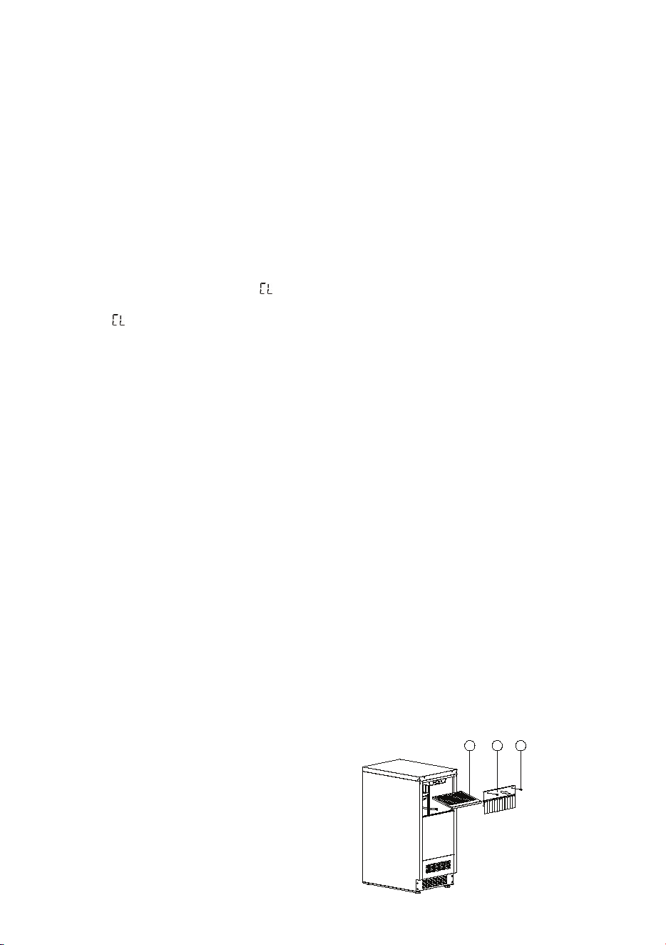
clean all components. The cleaner solution will foam when it contacts lime scale and mineral
deposits. Once the foaming stops, use a soft-bristle nylon brush, sponge or cloth (NOT a wire
brush) to carefully clean the parts. Disassemble the spray bar (remove the left and right silicone
plugs), remove nozzles and soak for 5 minutes. For heavily scaled parts, soak in solution for
15-20 minutes. Rinse all components with clean water.
6. While components are soaking, use the other 1/2 of the cleaner/water solution and a nylon
brush or cloth to clean inside of ice bin. Clean inside of door, door gasket, bin, top of evaporator
and evaporator bucket. Rinse all areas thoroughly with clean water.
7. Use 1/2 of the sanitizer/water mixture to sanitize all removed components. Use a cloth or
sponge to liberally apply the solution to all surfaces of the removed parts or soak the removed
parts in the sanitizer/solution.
8. Use the other 1/2 of the sanitizer/water solution and a sponge or cloth to sanitize the inside of
ice bin. Sanitize inside of door, door gasket, bin, top of evaporator and evaporator bucket.
9. Replace all removed components.
10. Add 1 oz. of undiluted Ice Machine Sanitizer into the water trough by lifting the water shutters
and pouring directly into the spray area. Then press the CLEAN key, initiating the clean cycle.
The display window will show and the ice machine will run in the CLEAN mode
automatically. This entire cycle lasts approximately 30 minutes.
11. The will flash in the display window to indicate the CLEAN cycle is complete. After cleaning,
drain off the waste water inside the water trough to a convenient container.
NOTE: Don’t drain off the waste water to the inside of the cabinet and remember to replace the
overflow tube securely.
12. Repeat steps 10 and 11 (without Ice Maker Cleaning Solution and Sanitizer) three times to rinse
the ice making system thoroughly.
13. Press and hold the POWER key for 5 seconds to switch off the unit to finish the above process.
Then press the POWER key to switch on the unit and press the ICE key, the machine will return
to the regular ice making mode. Discard the first batch of ice.
REMOVAL OF PARTS FOR CLEANING/SANITIZING
WARNING
Disconnect the electrical power to the ice machine and turn off the water supply before proceeding.
Turn off the electrical and water supply to the ice machine.
1. Remove all ice from the storage bin.
2. Remove the components that must be cleaned and sanitized as the following removal
procedures for these parts.
3. Soak the removed part(s) in a properly mixed solution of cleaner.
4. The cleaner will foam. Once the foaming stops use a soft-bristle nylon brush, sponge or cloth
(NOT a wire brush) to carefully clean the parts.
5. Thoroughly rinse all the parts with clean water.
6. Soak the removed parts in a properly mixed solution of sanitizer for 5 minutes.
7. Use a soft-bristle nylon brush, sponge or cloth (NOT a wire brush) to carefully sanitize the parts.
8. Use the sanitizing solution and a sponge or cloth to sanitize (wipe) the interior of the ice
machine and bin.
9. Install the removed parts.
10. Turn on the water and electrical supply.
Water Shutter and Ice Chute
Open the door and remove the two screws (1) on
the front side. Then you can pull and remove the
water shutter assembly (2) and then lift to
remove the ice chute (3).
Spray Bar and Overflow Tube
DESIGN 2 – For articulated hinge models
1. Pull the top decoration cover (3) upward and
remove it. Remove the cover caps (2) and then
remove the door by unscrewing the four screws
(1). Be careful to hold the door firmly after
2. removing the screws and place it on a padded
surface to avoid the risk of damage. Leave the
hinges open. (Figure 1)
3. Unscrew the four screws (4) to remove the top
and bottom articulated hinges. (Figure 2)
4. Pop out the cover caps on the left side of the
cabinet and use them to cover the screw holes
on the right-hand side.
5. Pull the top decoration cover (5) upward and remove it. Unscrew the two screws (6) and transfer the
retaining bracket (7) to the opposite side of the door. Refit the top decoration cover (5). (Figure 3)
6. Unscrew the screw (9) and transfer the bottom decoration cover (8) to the opposite side of the door.
(Figure 4)
7. Refit the articulated hinges to the opposite side of the door by using the four screws (3). (Repeat
step 2 in reverse.)
8. Refit the door to the opposite side. Then screw and tighten it after the door is leveled. (Repeat step 1
in reverse.)
DESIGN 3 – For panel ready models
1. Pull the top decoration cover (3) upward and
remove it. Remove the cover caps (2) and then
remove the door by unscrewing the four screws
(1). Be careful to hold the door firmly after
removing the screws and place it on a padded
surface to avoid the risk of damage. Leave the
hinges open. (Figure 1)
2. Unscrew the four screws (4) to remove the top
and bottom articulated hinges. (Figure 2)
3. Pop out the cover caps on the left side of the cabinet and use them to cover the screw holes on the
right-hand side.
4. Unscrew the two screws (5) and transfer the retaining bracket (6) to the opposite side of the door.
(Figure 3)
5. Refit the articulated hinges to the opposite side of the door by using the four screws (3). (Repeat
step 2 in reverse.)
6. Refit the door to the opposite side. Then screw and tighten it after the door is leveled. (Repeat step 1
in reverse.)
7. Refit the alternative top decoration cover included in the fittings on the top of door.
OVERLAY PANEL INSTALLATION INSTRUCTION
Door Panel Preparation
Depending on the model prepare the overlay panel to
the dimensions shown below. Then attach the handle
to the overlay panel by using the flat head screws and
drive the screws flush with the panel if needed.
NOTE:
H can be 28⅜" and 30". It depends on the actual product specification.
Weight of the overlay panel should not exceed 22 Lbs.
It is important to ensure that all drilled holes are drilled to the correct depth in order to
avoid splits in the wood when hardware is installed.
Drill the handle installation holes in the overlay panel according to the handle you are
planning to use. If reusing the handles came with the unit, drill two holes with holes
distance same as handle and diameter 5mm in the overlay panel.
use an extension cord with this appliance. However, if you must use an extension cord it is absolutely
necessary that it be a UL/CUL-listed, 3-wire grounding type appliance extension cord having a grounding
type plug and outlet and that the electrical rating of the cord be 115 volts and at least 10 amperes.
INSTALLING THE HANDLE
IMPORTANT: Do not overtighten the screws & do not use
power tools to install the handle.
DESIGN 1 –
Locate the handle (2) over the mounting stubs (1) of the
door and tighten the grub screws (3) with an Allen key to
secure the handle.
DESIGN 2 –
Remove the door gasket on the side you wish to install the
handle - you can see two designated holes for handle
installation.
Install the handle (3) tightly as shown above with two
screws (1) and flat washers (2) provided.
Replace the door gasket.
REVERSING THE DOOR HINGE
It is possible to reverse the door on this appliance, if
required.
To do so, follow the steps below:
Note: All parts removed must be saved to do the reinstallation of the door.
DESIGN 1 – For standard hinge models
1. Remove the bottom hinge (1) by unscrewing the
two lock screws (2). Be careful to hold the door
firmly after removing the screws. (Fig. 1)
2. Gently pull down to remove the door (3) from the
right top hinge and place it on a padded surface
to avoid the risk of damage. Then remove the
right top hinge (3). (Fig. 2 & 3)
3. Pop out the cover caps on the left side of cabinet
and use them to cover the screw holes on the
right hand side.
4. Screw the alternative left top hinge (4), included
in the fittings, on the left hand side of cabinet.
(Fig. 3)
5. Relocate the door to the designated position. Then screw the bottom hinge assembly on the left
designated position and tighten it after the door is leveled.
NOTE: Make sure that the socket and ON/OFF switch are easily accessible after the appliance has been
installed.
BUILT-UNDER INSTRUCTIONS
Make sure your installation does not block the front ventilation grill. If the unit is fully integrated to be
installed for fitting kitchen, make sure that the ventilation gaps in the plinth are at least 300 square
centimeters and remove the ventilation grilles, so that warm air can disperse unhindered. Otherwise the
appliance has to work harder, resulting in an increase in electricity consumption.
NOTE: When pushing the appliance into the niche, make sure that the mains cable does not get trapped.
CAUTION
To ensure the proper functioning of the appliance, air vents should never be blocked or covered.
ELECTRICAL CONNECTION
Check that the voltage marked on the product corresponds with your supply voltage
WARNING
Improper use of the grounded plug can result in the risk of electrical shock. If the power cord is damaged,
have it replaced by a qualified electrician or an authorized service center.
This appliance should be properly grounded for your safety. The power cord of this appliance is equipped
with a three-prong plug which mates with standard three-prong wall outlets to minimize the possibility of
electrical shock.
Do not under any circumstances cut or remove the third (ground) prong from the power cord supplied.
For personal safety, this appliance must be properly grounded.
This appliance requires a standard 115/120 Volt AC ~ 60Hz three-prong grounded electrical outlet. Have
the wall outlet and circuit checked by a qualified electrician to make sure the outlet is properly grounded.
When a standard 2-prong wall outlet is encountered, it is your responsibility and obligation to have it
replaced with a properly grounded 3-prong wall outlet.
To prevent accidental injury, the cord should be secured behind the appliance and not left exposed or
dangling.
The appliance should always be plugged into its own individual electrical outlet which has a voltage
rating that matches the rating label on the appliance. This provides the best performance and also
prevents overloading house wiring circuits that could cause a fire hazard from overheating. Never unplug
the appliance by pulling on the power cord. Always grip the plug firmly and pull straight out from the
receptacle. Repair or replace immediately all power cords that have become frayed or otherwise
damaged. Do not use a cord that shows cracks or abrasion damage along its length or at either end.
When moving the appliance, be careful not to damage the power cord.
EXTENSION CORD
Because of potential safety hazards under certain conditions, it is strongly recommended that you do not
3
2 1
BEFORE USING YOUR APPLIANCE
- Remove all exterior and interior packing. Clean the interior surface with lukewarm water using a soft
cloth. The unit may have residual odors at first, they will disappear as the unit cools.
- IMPORTANT: Before connecting the icemachine to the power source, let it stand upright for
approximately 24 hours. This will reduce the possibility of a malfunction in the cooling system
caused by handling during transportation.
- The door on this appliance can be opened either the left or the right side. The unit is delivered with
the door opening on the left side. Should you wish to open the door from the right, follow the
instructions "Reversing the door hinge".
- Install the handle on the door.
- Sanitize the ice machine. All ice machines are factory-operated and adjusted before shipment.
Normally, new installations do not require any adjustment.
INSTALLATION OF YOUR APPLIANCE
WARNING
This appliance must be installed in accordance with all local codes and ordinances.
• The appliances are designed to be built-in or recessed or free-standing installation.
• This ice machine should be properly installed by qualified personnel.
• WARNING: Flammable Refrigerant Used. Appliance should be installed in accordance with the
Safety Standard for Refrigeration Systems, ANSI/ASHRAE 15.
• Place your ice machine on a floor that is even and strong enough to support it when it is fully loaded.
It is very important for the ice machine to be level in order to work properly. To level your unit, adjust
the front adjustable legs at the bottom of the unit.
• For freestanding installation, 5 inches (127mm) of space between the back and sides of the unit are
suggested, which allows the proper air circulation to cool the compressor and condenser for energy
saving. Even for built-in installation, it is a must to keep ¾" (5mm) space on each side and at the top
to ensure proper service access and efficient ventilation. Take care that the air vent at the front of
the appliance must never be covered or blocked in any way.
• Installation of the ice maker requires a cold water supply inlet of ¼-in. (6.35mm) soft copper tubing
with a shut-off valve.
• Locate the unit away from direct sunlight and sources of heat (stove, heater, radiator, etc.). Direct
sunlight may affect the acrylic coating and heat sources may increase electrical consumption.
Extreme cold ambient temperatures may also cause the unit not to perform properly.
• Avoid locating the unit in damp areas.
• Plug the unit into an exclusive, easily accessible and properly grounded wall outlet. Do not under any
circumstances cut or remove the third (ground) prong from the power cord. Any questions concern-
ing power and/or earthing should be directed towards a qualified electrician or an authorized
products service centre.
• The appliance must be installed to all electrical, plumbing, water and drain connections in
accordance with state and local codes.
• The equipment must be installed with adequate backflow protection to comply with applicable
federal, state and local codes.
• It is strongly recommended that a water filter be used. A filter, if it is of the proper type, can remove
taste and odors as well as particles. Some water is very hard, and softened water may result in
white, mushy cubes that stick together. Deionized water is not recommended.
Door Panel Installation
Attach the wood overlay panel (1) on the door (2) by using the four wood screws ST4x15 Type AB Philips
(3).
WATER SUPPLY AND DRAIN REQUIREMENTS
Prepare water supply line and drain before installation of your ice machine. Installation requires a 1/4" ID
copper cold water line and compression fitting (not supplied).
The ice machine IM50 is supplied with an automatic drain pump system. The ice machine IM30 is
supplied with a drain hose for gravity draining. Both drain methods require routing to an open site drain.
Do not connect directly to drain line as bacteria from drain line may contaminate the ice machine.
Make certain the hoses are not pinched or kinked or damaged during installation.
Check for leaks after connection.
WATER INLET LINES
CAUTION
Copper tubing is recommended for the water supply line. Water supply tubing made of 1/4" plastic is not
recommended since it greatly increases the potential for water leaks. Manufacturer will not be responsible
for any damage if plastic tubing is used for the supply line.
Follow these guidelines to install water inlet lines:
▪ Do not connect the ice machine to a hot water supply. Be sure all hot water restrictors installed for
other equipment are working. (Check valves on sink faucets, dishwashers, etc.)
▪ If water pressure exceeds the maximum recommended pressure (80 psi - 55 bar), obtain a water
pressure regulator.
▪ Install a water shut-off valve for the ice making water lines.
▪ Insulate the water inlet line to prevent condensation.
▪ Install tubing only in areas where temperatures will remain above freezing.
▪ Leave a coil of copper tubing to allow the ice maker to be pulled out of the cabinet or away from the
wall for service.
DRAIN CONNECTIONS (FACTORY SUPPLIED)
Follow these guidelines when installing drain lines to prevent drain water from flowing back into the ice
machine and storage bin:
▪ Drain lines must have a 1.5 inch drop per 5 feet of run (2.5 cm per meter), and must not create traps.
▪ The floor drain must be large enough to accommodate drainage from all drains.
▪ Drain pump discharge line must terminate at an open site drain.
▪ The maximum length of drain hose is 5 feet (1.5
m).
▪ The maximum rise of drain hose is 2.6 feet (0.8
m).
▪ Pour 3000ml of water into the ice storage bin to
check for leaks in the drainage system.
WATER SUPPLY AND DRAIN LINE
SIZING/CONNECTIONS
CAUTION
Plumbing must conform to state and local codes.
NOTE: If air temperature is less than 60°F (15.5°C), water
temperature must be equal to or greater than 50°F (10°C).
INSTALLATION PROCEDURE
1. Prepare the site by following the instructions under Electrical Connection and Water Supply and
Drain Requirements.
2. Remove ice machine from carton.
3. Inspect for damage.
4. Remove literature packet and drain hose from inside the ice machine.
5. Adjust leg levelers.
6. Reverse door if desired. See Reversing the Door Hinge.
7. Install drain hose to drain on back of ice machine and route to open site drain.
8. Use compression fitting to connect the Water Inlet on back of ice machine to the prepared 1/4" ID
cold water line.
9. Open the shut-off valve on the water line.
10. Connect electrical plug to grounded (three-prong), polarized outlet.
11. Place ice machine back in position and check leveling again. Make any necessary adjustments.
12. Prepare sanitizer solution and sanitize the ice machine according to Cleaning/Sanitizing the Ice
Making System.
13. At initial start-up, ice machine will need approximately 45 minutes to freeze.
INSTALLATION CHECK LIST
▪ Is the Ice Machine level?!
▪ Has all of the packing been removed?
▪ Have all of the electrical and water connections been made?
▪ Has the supply voltage been tested and checked against the rating on the nameplate?
▪ Is there proper clearance around the ice machine for air circulation?
▪ Has the ice machine been installed where ambient temperatures will remain in the range of 41° -
100°F (5° - 38°C)?
▪ Has the ice machine been installed where the incoming water temperature will remain in the range
of 41° - 90°F (5° - 32°C)?
▪ Has the water supply pressure been checked to ensure a minimum of 20 psig with a static pressure
not to exceed 80 psig?
▪ Is the ice machine drain line routed to an open site drain?
▪ Are all electrical leads free from contact with refrigeration lines and moving equipment?
▪ Has the ice machine and bin been sanitized?
▪ Is the ice machine plugged into a properly grounded, polarized receptacle?
▪ Have the water and drain connections been examined for leaks?
WARNING
▪ To avoid possible injury due to electric shock, disconnect the power cord or turn off power at
the circuit breaker panel or fuse box and shut off the water line before cleaning the appliance.
▪ Clean only the parts of the appliance listed in this manual. Clean them only in the manner
specified.
▪ Do not use a steam cleaner to clean this appliance. Steam could penetrate the electrical
components and cause a short circuit.
▪ Do not allow water or cleaning fluids to penetrate into the electrical components or ventilation
grill.
▪ Use only the types of cleaning solutions specified in this manual. NEVER clean appliance parts
with flammable fluids.
▪ Do not use abrasives such as steel wool, scouring pads, rough sponges or scrub brushes.
GENERAL
Basic hygiene and maintenance of your Ice Machine, will increase its reliability, increase
performance, and help save on water and power consumption. Ice production will be maintained and
unwanted repairs due to maintenance issues will be minimized.
CAUTION
If the ice machine is left unused after prolonged shutdown, before the next use it must be thoroughly
cleaned. Follow carefully any instructions provided for cleaning or use of sanitizing solutions. Do not
leave any solution inside the ice machine after cleaning.
The following minimum maintenance procedures are recommended in order to ensure reliable,
trouble-free operation and maximum ice production. If the ice machine requires more frequent
cleaning and sanitizing, consult a qualified service company to test the water quality and
recommend appropriate water treatment. An extremely dirty ice machine must be taken apart for
cleaning and sanitizing.
▪ Clean cabinet exterior: Weekly, at start-up and after prolonged shutdown
▪ Clean/sanitize ice bin: Semi Annual, at start-up and after prolonged shutdown
▪ Clean/sanitize the ice making system: Semi Annual, at start-up and after prolonged shutdown
▪ Full cleaning and sanitizing: Annual.
WARNING
If you do not understand the procedures or the safety precautions that must be followed, call your
local service representative to perform the maintenance procedures for you.
CLEANING THE CABINET EXTERIOR
Clean the outside cabinet of the ice machine as often as necessary to maintain cleanliness. Wash it
with warm water and mild liquid detergent. Rinse well and wipe dry with a clean soft cloth.
Do not clean the stainless steel with steel wool pads. Suggest to using an all-in-one stainless steel
cleaner to clean the stainless steel and always clean in the direction of grain.
CLEANING THE INTERIOR
The ice storage bin should be sanitized occasionally. Clean the water trough before the ice machine
is used first time and reused after prolonged shutdown. It is usually convenient to sanitize the trough
after the ice making system has been cleaned, and the ice storage bin is empty.
1. Disconnect the power to the unit.
2. Open the door. With a clean cloth, wipe down the interior of the unit with a sanitizing solution
made of 1 ounce of household bleach or chlorine and 2 gallons of hot water (95°F – 115°F)
water.
3. Rinse thoroughly with clear water.
4. Reconnect power to the unit.
CLEANING/SANITIZING THE ICE MAKING SYSTEM
Minerals that are removed from the water during the freezing cycle will eventually form a hard, scaly
deposit in the water system. Cleaning the system regularly helps remove the mineral scale buildup.
How often to clean the system depends upon how hard your water is or how effective your filtration
may be. With hard water of 15 to 20 grains/gal. (4 to 5 grains/liter), you may need to clean the
system as often as once every 6 months.
Use ice machine cleaner to remove lime scale or other mineral deposits. Ice machine sanitizer
disinfects and removes algae and slime.
Make sure that all the ice is off the evaporator. If ice is being formed, wait until the cycle is
completed, then press and hold the POWER key for 5 seconds to switch off the unit.
Remove all ice from the storage bin.
Keep the ice machine connected to the water supply. Add 8 oz. of Nickel-Safe Ice Maker Cleaner
Solution into the water trough by lifting the water shutters and pouring directly into the spray area.
Press the POWER key to switch on the unit and then press the CLEAN key to initiate the clean cycle.
The display window will show and the machine will run in the CLEAN mode automatically. This
entire cycle lasts approximately 30 minutes.
WARNING
The ice machine cleaner contains acids. Use rubber gloves to protect hands. Carefully read the
material safety instructions on the container of the ice machine cleaner and sanitizer.
DO NOT use or mix with any other solvent-based cleaner products.
Discard the first batch of ice produced after cleaning.
FULL CLEANING/SANITIZING PROCEDURE
Ice machine cleaner is used to remove lime scale and other mineral deposits. Ice machine sanitizer
disinfects and removes algae and slime.
NOTE: All ice must be removed from the bin.
1. Remove all ice from the storage bin.
2. Keep the ice machine connected to the water supply. Add 8 oz. of Nickel-Safe Ice Maker
Cleaner Solution into the water trough by lifting the water shutters and pouring directly into the
spray area. Press the POWER key to switch on the unit and then press the CLEAN key to initiate
the clean cycle. The display window will show and the machine will run in the CLEAN mode
automatically. This entire cycle lasts approximately 30 minutes.
3. The will flash in the display window to indicate the CLEAN cycle is complete. After cleaning,
drain off the waste water inside the water trough to a convenient container by removing the
overflow tube. NOTE: Don't drain off the waste water to the inside of the cabinet.
4. When the cleaning process stops, disconnect power and remove all parts as described in
Removal of Parts for Cleaning and Sanitizing.
5. Take all removed components to a sink for cleaning. Use 1/2 of the cleaner/water mixture to
Disconnect the water hose (3) from the spray bar assembly (2). Grasp two ends of the spray bar, lift
up and remove from seat formed in water trough. Gently pull out the two silicone plugs (1) and then
you can clean nozzle frame and the gap of nozzle. Nozzles are not suggested to be removed for
cleaning. Gently lift the overflow tube (4) inside the water trough and clean it. Make sure to replace
the overflow tube in the correct position after cleaning, otherwise, draining will not stop, with the
product rendered unable to make ice. Gently pull to remove the filter screen (5) inside the water
trough and clean it.
Top and Evaporator Cover
WARNING
Disconnect the electrical power to the ice machine and turn off the water supply before proceeding.
▪ Remove the door.
▪ Slide down to remove the rear cover (2) by unscrewing the four screws (1).
▪ Slide down to remove the rear panel (4) by unscrewing the two screws (3).
▪ Remove the top cover (7) by unscrewing the two screws (6). Now you can remove the
evaporator cover (5).
POWER FAILURE
In the event of a power interruption, all previous settings are automatically memorized. If power is
interrupted (power surge, breaker switch, etc.), and then powered up again, the unit will operate with
the last temperature set-point.
VACATION TIME
Short holidays: Leave the unit in operation for holidays of less than three weeks.
Long absences: If the appliance will not be used for several months, or is to be moved to another
place, exposed to an ambient temperatures of 32°F (0°C) or below, please follow up the below
instructions:
CAUTION
If water is allowed to remain in the ice machine in freezing temperatures, severe damage to some
components could result. Damage of this nature is not covered by the warranty.
1. Perform a cleaning and sanitizing procedure to prevent mildew growth.
2. Disconnect the electric supply at the main electrical power source.
3. Turn off the water supply.
4. Disconnect and drain the incoming ice-making water line at the rear of the ice machine.
5. Remove any remaining ice and water from the storage bin and dry the bin.
6. Drain off all water in the water trough.
7. Make sure water is not trapped in any of the water or drain lines. Compressed air can be used
to blow out the lines.
8. Use a spray bottle and a solution of sanitizer/water (0.50 oz/1 gal) and spray all interior
surfaces. Do not rinse, allow to air dry.
9. Leave the door partially open to allow for circulation and prevent mold or mildew growth.
MOVING YOUR APPLIANCE
Unplug the power plug from the electrical outlet. Disconnect the water line.
Remove the ice from the bin and drain off the water. Than fix all moving parts.
Raise the adjustable legs up to the base to avoid damage.
Tape the door shut.
Transport the machine only in the upright position. Also protect the outside of the appliance with a
blanket or similar item.
ENERGY SAVING TIPS
Should the unit be left empty for long periods of time, it is suggested that the appliance is
unplugged, and after careful cleaning, leave the door ajar to allow air to circulate inside the cabinet in
order to avoid possible condensation, mold or odors forming.
The machine should be installed in the coolest area of the room, away from heat producing
appliances, and out of the direct sunlight.
Ensure that the unit is adequately ventilated. Never cover air vents. Clean dust and dirt from the
condenser at regular intervals.
Only open the door for as long as necessary and for as short a time as possible.
18
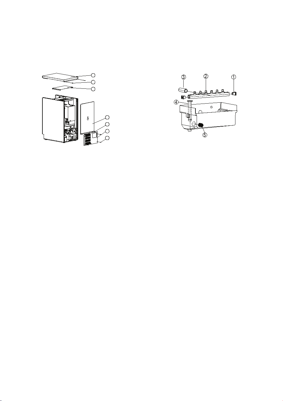
clean all components. The cleaner solution will foam when it contacts lime scale and mineral
deposits. Once the foaming stops, use a soft-bristle nylon brush, sponge or cloth (NOT a wire
brush) to carefully clean the parts. Disassemble the spray bar (remove the left and right silicone
plugs), remove nozzles and soak for 5 minutes. For heavily scaled parts, soak in solution for
15-20 minutes. Rinse all components with clean water.
6. While components are soaking, use the other 1/2 of the cleaner/water solution and a nylon
brush or cloth to clean inside of ice bin. Clean inside of door, door gasket, bin, top of evaporator
and evaporator bucket. Rinse all areas thoroughly with clean water.
7. Use 1/2 of the sanitizer/water mixture to sanitize all removed components. Use a cloth or
sponge to liberally apply the solution to all surfaces of the removed parts or soak the removed
parts in the sanitizer/solution.
8. Use the other 1/2 of the sanitizer/water solution and a sponge or cloth to sanitize the inside of
ice bin. Sanitize inside of door, door gasket, bin, top of evaporator and evaporator bucket.
9. Replace all removed components.
10. Add 1 oz. of undiluted Ice Machine Sanitizer into the water trough by lifting the water shutters
and pouring directly into the spray area. Then press the CLEAN key, initiating the clean cycle.
The display window will show and the ice machine will run in the CLEAN mode
automatically. This entire cycle lasts approximately 30 minutes.
11. The will flash in the display window to indicate the CLEAN cycle is complete. After cleaning,
drain off the waste water inside the water trough to a convenient container.
NOTE: Don’t drain off the waste water to the inside of the cabinet and remember to replace the
overflow tube securely.
12. Repeat steps 10 and 11 (without Ice Maker Cleaning Solution and Sanitizer) three times to rinse
the ice making system thoroughly.
13. Press and hold the POWER key for 5 seconds to switch off the unit to finish the above process.
Then press the POWER key to switch on the unit and press the ICE key, the machine will return
to the regular ice making mode. Discard the first batch of ice.
REMOVAL OF PARTS FOR CLEANING/SANITIZING
WARNING
Disconnect the electrical power to the ice machine and turn off the water supply before proceeding.
Turn off the electrical and water supply to the ice machine.
1. Remove all ice from the storage bin.
2. Remove the components that must be cleaned and sanitized as the following removal
procedures for these parts.
3. Soak the removed part(s) in a properly mixed solution of cleaner.
4. The cleaner will foam. Once the foaming stops use a soft-bristle nylon brush, sponge or cloth
(NOT a wire brush) to carefully clean the parts.
5. Thoroughly rinse all the parts with clean water.
6. Soak the removed parts in a properly mixed solution of sanitizer for 5 minutes.
7. Use a soft-bristle nylon brush, sponge or cloth (NOT a wire brush) to carefully sanitize the parts.
8. Use the sanitizing solution and a sponge or cloth to sanitize (wipe) the interior of the ice
machine and bin.
9. Install the removed parts.
10. Turn on the water and electrical supply.
Water Shutter and Ice Chute
Open the door and remove the two screws (1) on
the front side. Then you can pull and remove the
water shutter assembly (2) and then lift to
remove the ice chute (3).
Spray Bar and Overflow Tube
DESIGN 2 – For articulated hinge models
1. Pull the top decoration cover (3) upward and
remove it. Remove the cover caps (2) and then
remove the door by unscrewing the four screws
(1). Be careful to hold the door firmly after
2. removing the screws and place it on a padded
surface to avoid the risk of damage. Leave the
hinges open. (Figure 1)
3. Unscrew the four screws (4) to remove the top
and bottom articulated hinges. (Figure 2)
4. Pop out the cover caps on the left side of the
cabinet and use them to cover the screw holes
on the right-hand side.
5. Pull the top decoration cover (5) upward and remove it. Unscrew the two screws (6) and transfer the
retaining bracket (7) to the opposite side of the door. Refit the top decoration cover (5). (Figure 3)
6. Unscrew the screw (9) and transfer the bottom decoration cover (8) to the opposite side of the door.
(Figure 4)
7. Refit the articulated hinges to the opposite side of the door by using the four screws (3). (Repeat
step 2 in reverse.)
8. Refit the door to the opposite side. Then screw and tighten it after the door is leveled. (Repeat step 1
in reverse.)
DESIGN 3 – For panel ready models
1. Pull the top decoration cover (3) upward and
remove it. Remove the cover caps (2) and then
remove the door by unscrewing the four screws
(1). Be careful to hold the door firmly after
removing the screws and place it on a padded
surface to avoid the risk of damage. Leave the
hinges open. (Figure 1)
2. Unscrew the four screws (4) to remove the top
and bottom articulated hinges. (Figure 2)
3. Pop out the cover caps on the left side of the cabinet and use them to cover the screw holes on the
right-hand side.
4. Unscrew the two screws (5) and transfer the retaining bracket (6) to the opposite side of the door.
(Figure 3)
5. Refit the articulated hinges to the opposite side of the door by using the four screws (3). (Repeat
step 2 in reverse.)
6. Refit the door to the opposite side. Then screw and tighten it after the door is leveled. (Repeat step 1
in reverse.)
7. Refit the alternative top decoration cover included in the fittings on the top of door.
OVERLAY PANEL INSTALLATION INSTRUCTION
Door Panel Preparation
Depending on the model prepare the overlay panel to
the dimensions shown below. Then attach the handle
to the overlay panel by using the flat head screws and
drive the screws flush with the panel if needed.
NOTE:
H can be 28⅜" and 30". It depends on the actual product specification.
Weight of the overlay panel should not exceed 22 Lbs.
It is important to ensure that all drilled holes are drilled to the correct depth in order to
avoid splits in the wood when hardware is installed.
Drill the handle installation holes in the overlay panel according to the handle you are
planning to use. If reusing the handles came with the unit, drill two holes with holes
distance same as handle and diameter 5mm in the overlay panel.
use an extension cord with this appliance. However, if you must use an extension cord it is absolutely
necessary that it be a UL/CUL-listed, 3-wire grounding type appliance extension cord having a grounding
type plug and outlet and that the electrical rating of the cord be 115 volts and at least 10 amperes.
INSTALLING THE HANDLE
IMPORTANT: Do not overtighten the screws & do not use
power tools to install the handle.
DESIGN 1 –
Locate the handle (2) over the mounting stubs (1) of the
door and tighten the grub screws (3) with an Allen key to
secure the handle.
DESIGN 2 –
Remove the door gasket on the side you wish to install the
handle - you can see two designated holes for handle
installation.
Install the handle (3) tightly as shown above with two
screws (1) and flat washers (2) provided.
Replace the door gasket.
REVERSING THE DOOR HINGE
It is possible to reverse the door on this appliance, if
required.
To do so, follow the steps below:
Note: All parts removed must be saved to do the reinstallation of the door.
DESIGN 1 – For standard hinge models
1. Remove the bottom hinge (1) by unscrewing the
two lock screws (2). Be careful to hold the door
firmly after removing the screws. (Fig. 1)
2. Gently pull down to remove the door (3) from the
right top hinge and place it on a padded surface
to avoid the risk of damage. Then remove the
right top hinge (3). (Fig. 2 & 3)
3. Pop out the cover caps on the left side of cabinet
and use them to cover the screw holes on the
right hand side.
4. Screw the alternative left top hinge (4), included
in the fittings, on the left hand side of cabinet.
(Fig. 3)
5. Relocate the door to the designated position. Then screw the bottom hinge assembly on the left
designated position and tighten it after the door is leveled.
NOTE: Make sure that the socket and ON/OFF switch are easily accessible after the appliance has been
installed.
BUILT-UNDER INSTRUCTIONS
Make sure your installation does not block the front ventilation grill. If the unit is fully integrated to be
installed for fitting kitchen, make sure that the ventilation gaps in the plinth are at least 300 square
centimeters and remove the ventilation grilles, so that warm air can disperse unhindered. Otherwise the
appliance has to work harder, resulting in an increase in electricity consumption.
NOTE: When pushing the appliance into the niche, make sure that the mains cable does not get trapped.
CAUTION
To ensure the proper functioning of the appliance, air vents should never be blocked or covered.
ELECTRICAL CONNECTION
Check that the voltage marked on the product corresponds with your supply voltage
WARNING
Improper use of the grounded plug can result in the risk of electrical shock. If the power cord is damaged,
have it replaced by a qualified electrician or an authorized service center.
This appliance should be properly grounded for your safety. The power cord of this appliance is equipped
with a three-prong plug which mates with standard three-prong wall outlets to minimize the possibility of
electrical shock.
Do not under any circumstances cut or remove the third (ground) prong from the power cord supplied.
For personal safety, this appliance must be properly grounded.
This appliance requires a standard 115/120 Volt AC ~ 60Hz three-prong grounded electrical outlet. Have
the wall outlet and circuit checked by a qualified electrician to make sure the outlet is properly grounded.
When a standard 2-prong wall outlet is encountered, it is your responsibility and obligation to have it
replaced with a properly grounded 3-prong wall outlet.
To prevent accidental injury, the cord should be secured behind the appliance and not left exposed or
dangling.
The appliance should always be plugged into its own individual electrical outlet which has a voltage
rating that matches the rating label on the appliance. This provides the best performance and also
prevents overloading house wiring circuits that could cause a fire hazard from overheating. Never unplug
the appliance by pulling on the power cord. Always grip the plug firmly and pull straight out from the
receptacle. Repair or replace immediately all power cords that have become frayed or otherwise
damaged. Do not use a cord that shows cracks or abrasion damage along its length or at either end.
When moving the appliance, be careful not to damage the power cord.
EXTENSION CORD
Because of potential safety hazards under certain conditions, it is strongly recommended that you do not
7
6
5
4
3
2
1
BEFORE USING YOUR APPLIANCE
- Remove all exterior and interior packing. Clean the interior surface with lukewarm water using a soft
cloth. The unit may have residual odors at first, they will disappear as the unit cools.
- IMPORTANT: Before connecting the icemachine to the power source, let it stand upright for
approximately 24 hours. This will reduce the possibility of a malfunction in the cooling system
caused by handling during transportation.
- The door on this appliance can be opened either the left or the right side. The unit is delivered with
the door opening on the left side. Should you wish to open the door from the right, follow the
instructions "Reversing the door hinge".
- Install the handle on the door.
- Sanitize the ice machine. All ice machines are factory-operated and adjusted before shipment.
Normally, new installations do not require any adjustment.
INSTALLATION OF YOUR APPLIANCE
WARNING
This appliance must be installed in accordance with all local codes and ordinances.
• The appliances are designed to be built-in or recessed or free-standing installation.
• This ice machine should be properly installed by qualified personnel.
• WARNING: Flammable Refrigerant Used. Appliance should be installed in accordance with the
Safety Standard for Refrigeration Systems, ANSI/ASHRAE 15.
• Place your ice machine on a floor that is even and strong enough to support it when it is fully loaded.
It is very important for the ice machine to be level in order to work properly. To level your unit, adjust
the front adjustable legs at the bottom of the unit.
• For freestanding installation, 5 inches (127mm) of space between the back and sides of the unit are
suggested, which allows the proper air circulation to cool the compressor and condenser for energy
saving. Even for built-in installation, it is a must to keep ¾" (5mm) space on each side and at the top
to ensure proper service access and efficient ventilation. Take care that the air vent at the front of
the appliance must never be covered or blocked in any way.
• Installation of the ice maker requires a cold water supply inlet of ¼-in. (6.35mm) soft copper tubing
with a shut-off valve.
• Locate the unit away from direct sunlight and sources of heat (stove, heater, radiator, etc.). Direct
sunlight may affect the acrylic coating and heat sources may increase electrical consumption.
Extreme cold ambient temperatures may also cause the unit not to perform properly.
• Avoid locating the unit in damp areas.
• Plug the unit into an exclusive, easily accessible and properly grounded wall outlet. Do not under any
circumstances cut or remove the third (ground) prong from the power cord. Any questions concern-
ing power and/or earthing should be directed towards a qualified electrician or an authorized
products service centre.
• The appliance must be installed to all electrical, plumbing, water and drain connections in
accordance with state and local codes.
• The equipment must be installed with adequate backflow protection to comply with applicable
federal, state and local codes.
• It is strongly recommended that a water filter be used. A filter, if it is of the proper type, can remove
taste and odors as well as particles. Some water is very hard, and softened water may result in
white, mushy cubes that stick together. Deionized water is not recommended.
Door Panel Installation
Attach the wood overlay panel (1) on the door (2) by using the four wood screws ST4x15 Type AB Philips
(3).
WATER SUPPLY AND DRAIN REQUIREMENTS
Prepare water supply line and drain before installation of your ice machine. Installation requires a 1/4" ID
copper cold water line and compression fitting (not supplied).
The ice machine IM50 is supplied with an automatic drain pump system. The ice machine IM30 is
supplied with a drain hose for gravity draining. Both drain methods require routing to an open site drain.
Do not connect directly to drain line as bacteria from drain line may contaminate the ice machine.
Make certain the hoses are not pinched or kinked or damaged during installation.
Check for leaks after connection.
WATER INLET LINES
CAUTION
Copper tubing is recommended for the water supply line. Water supply tubing made of 1/4" plastic is not
recommended since it greatly increases the potential for water leaks. Manufacturer will not be responsible
for any damage if plastic tubing is used for the supply line.
Follow these guidelines to install water inlet lines:
▪ Do not connect the ice machine to a hot water supply. Be sure all hot water restrictors installed for
other equipment are working. (Check valves on sink faucets, dishwashers, etc.)
▪ If water pressure exceeds the maximum recommended pressure (80 psi - 55 bar), obtain a water
pressure regulator.
▪ Install a water shut-off valve for the ice making water lines.
▪ Insulate the water inlet line to prevent condensation.
▪ Install tubing only in areas where temperatures will remain above freezing.
▪ Leave a coil of copper tubing to allow the ice maker to be pulled out of the cabinet or away from the
wall for service.
DRAIN CONNECTIONS (FACTORY SUPPLIED)
Follow these guidelines when installing drain lines to prevent drain water from flowing back into the ice
machine and storage bin:
▪ Drain lines must have a 1.5 inch drop per 5 feet of run (2.5 cm per meter), and must not create traps.
▪ The floor drain must be large enough to accommodate drainage from all drains.
▪ Drain pump discharge line must terminate at an open site drain.
▪ The maximum length of drain hose is 5 feet (1.5
m).
▪ The maximum rise of drain hose is 2.6 feet (0.8
m).
▪ Pour 3000ml of water into the ice storage bin to
check for leaks in the drainage system.
WATER SUPPLY AND DRAIN LINE
SIZING/CONNECTIONS
CAUTION
Plumbing must conform to state and local codes.
NOTE: If air temperature is less than 60°F (15.5°C), water
temperature must be equal to or greater than 50°F (10°C).
INSTALLATION PROCEDURE
1. Prepare the site by following the instructions under Electrical Connection and Water Supply and
Drain Requirements.
2. Remove ice machine from carton.
3. Inspect for damage.
4. Remove literature packet and drain hose from inside the ice machine.
5. Adjust leg levelers.
6. Reverse door if desired. See Reversing the Door Hinge.
7. Install drain hose to drain on back of ice machine and route to open site drain.
8. Use compression fitting to connect the Water Inlet on back of ice machine to the prepared 1/4" ID
cold water line.
9. Open the shut-off valve on the water line.
10. Connect electrical plug to grounded (three-prong), polarized outlet.
11. Place ice machine back in position and check leveling again. Make any necessary adjustments.
12. Prepare sanitizer solution and sanitize the ice machine according to Cleaning/Sanitizing the Ice
Making System.
13. At initial start-up, ice machine will need approximately 45 minutes to freeze.
INSTALLATION CHECK LIST
▪ Is the Ice Machine level?!
▪ Has all of the packing been removed?
▪ Have all of the electrical and water connections been made?
▪ Has the supply voltage been tested and checked against the rating on the nameplate?
▪ Is there proper clearance around the ice machine for air circulation?
▪ Has the ice machine been installed where ambient temperatures will remain in the range of 41° -
100°F (5° - 38°C)?
▪ Has the ice machine been installed where the incoming water temperature will remain in the range
of 41° - 90°F (5° - 32°C)?
▪ Has the water supply pressure been checked to ensure a minimum of 20 psig with a static pressure
not to exceed 80 psig?
▪ Is the ice machine drain line routed to an open site drain?
▪ Are all electrical leads free from contact with refrigeration lines and moving equipment?
▪ Has the ice machine and bin been sanitized?
▪ Is the ice machine plugged into a properly grounded, polarized receptacle?
▪ Have the water and drain connections been examined for leaks?
WARNING
▪ To avoid possible injury due to electric shock, disconnect the power cord or turn off power at
the circuit breaker panel or fuse box and shut off the water line before cleaning the appliance.
▪ Clean only the parts of the appliance listed in this manual. Clean them only in the manner
specified.
▪ Do not use a steam cleaner to clean this appliance. Steam could penetrate the electrical
components and cause a short circuit.
▪ Do not allow water or cleaning fluids to penetrate into the electrical components or ventilation
grill.
▪ Use only the types of cleaning solutions specified in this manual. NEVER clean appliance parts
with flammable fluids.
▪ Do not use abrasives such as steel wool, scouring pads, rough sponges or scrub brushes.
GENERAL
Basic hygiene and maintenance of your Ice Machine, will increase its reliability, increase
performance, and help save on water and power consumption. Ice production will be maintained and
unwanted repairs due to maintenance issues will be minimized.
CAUTION
If the ice machine is left unused after prolonged shutdown, before the next use it must be thoroughly
cleaned. Follow carefully any instructions provided for cleaning or use of sanitizing solutions. Do not
leave any solution inside the ice machine after cleaning.
The following minimum maintenance procedures are recommended in order to ensure reliable,
trouble-free operation and maximum ice production. If the ice machine requires more frequent
cleaning and sanitizing, consult a qualified service company to test the water quality and
recommend appropriate water treatment. An extremely dirty ice machine must be taken apart for
cleaning and sanitizing.
▪ Clean cabinet exterior: Weekly, at start-up and after prolonged shutdown
▪ Clean/sanitize ice bin: Semi Annual, at start-up and after prolonged shutdown
▪ Clean/sanitize the ice making system: Semi Annual, at start-up and after prolonged shutdown
▪ Full cleaning and sanitizing: Annual.
WARNING
If you do not understand the procedures or the safety precautions that must be followed, call your
local service representative to perform the maintenance procedures for you.
CLEANING THE CABINET EXTERIOR
Clean the outside cabinet of the ice machine as often as necessary to maintain cleanliness. Wash it
with warm water and mild liquid detergent. Rinse well and wipe dry with a clean soft cloth.
Do not clean the stainless steel with steel wool pads. Suggest to using an all-in-one stainless steel
cleaner to clean the stainless steel and always clean in the direction of grain.
CLEANING THE INTERIOR
The ice storage bin should be sanitized occasionally. Clean the water trough before the ice machine
is used first time and reused after prolonged shutdown. It is usually convenient to sanitize the trough
after the ice making system has been cleaned, and the ice storage bin is empty.
1. Disconnect the power to the unit.
2. Open the door. With a clean cloth, wipe down the interior of the unit with a sanitizing solution
made of 1 ounce of household bleach or chlorine and 2 gallons of hot water (95°F – 115°F)
water.
3. Rinse thoroughly with clear water.
4. Reconnect power to the unit.
CLEANING/SANITIZING THE ICE MAKING SYSTEM
Minerals that are removed from the water during the freezing cycle will eventually form a hard, scaly
deposit in the water system. Cleaning the system regularly helps remove the mineral scale buildup.
How often to clean the system depends upon how hard your water is or how effective your filtration
may be. With hard water of 15 to 20 grains/gal. (4 to 5 grains/liter), you may need to clean the
system as often as once every 6 months.
Use ice machine cleaner to remove lime scale or other mineral deposits. Ice machine sanitizer
disinfects and removes algae and slime.
Make sure that all the ice is off the evaporator. If ice is being formed, wait until the cycle is
completed, then press and hold the POWER key for 5 seconds to switch off the unit.
Remove all ice from the storage bin.
Keep the ice machine connected to the water supply. Add 8 oz. of Nickel-Safe Ice Maker Cleaner
Solution into the water trough by lifting the water shutters and pouring directly into the spray area.
Press the POWER key to switch on the unit and then press the CLEAN key to initiate the clean cycle.
The display window will show and the machine will run in the CLEAN mode automatically. This
entire cycle lasts approximately 30 minutes.
WARNING
The ice machine cleaner contains acids. Use rubber gloves to protect hands. Carefully read the
material safety instructions on the container of the ice machine cleaner and sanitizer.
DO NOT use or mix with any other solvent-based cleaner products.
Discard the first batch of ice produced after cleaning.
FULL CLEANING/SANITIZING PROCEDURE
Ice machine cleaner is used to remove lime scale and other mineral deposits. Ice machine sanitizer
disinfects and removes algae and slime.
NOTE: All ice must be removed from the bin.
1. Remove all ice from the storage bin.
2. Keep the ice machine connected to the water supply. Add 8 oz. of Nickel-Safe Ice Maker
Cleaner Solution into the water trough by lifting the water shutters and pouring directly into the
spray area. Press the POWER key to switch on the unit and then press the CLEAN key to initiate
the clean cycle. The display window will show and the machine will run in the CLEAN mode
automatically. This entire cycle lasts approximately 30 minutes.
3. The will flash in the display window to indicate the CLEAN cycle is complete. After cleaning,
drain off the waste water inside the water trough to a convenient container by removing the
overflow tube. NOTE: Don't drain off the waste water to the inside of the cabinet.
4. When the cleaning process stops, disconnect power and remove all parts as described in
Removal of Parts for Cleaning and Sanitizing.
5. Take all removed components to a sink for cleaning. Use 1/2 of the cleaner/water mixture to
Disconnect the water hose (3) from the spray bar assembly (2). Grasp two ends of the spray bar, lift
up and remove from seat formed in water trough. Gently pull out the two silicone plugs (1) and then
you can clean nozzle frame and the gap of nozzle. Nozzles are not suggested to be removed for
cleaning. Gently lift the overflow tube (4) inside the water trough and clean it. Make sure to replace
the overflow tube in the correct position after cleaning, otherwise, draining will not stop, with the
product rendered unable to make ice. Gently pull to remove the filter screen (5) inside the water
trough and clean it.
Top and Evaporator Cover
WARNING
Disconnect the electrical power to the ice machine and turn off the water supply before proceeding.
▪ Remove the door.
▪ Slide down to remove the rear cover (2) by unscrewing the four screws (1).
▪ Slide down to remove the rear panel (4) by unscrewing the two screws (3).
▪ Remove the top cover (7) by unscrewing the two screws (6). Now you can remove the
evaporator cover (5).
POWER FAILURE
In the event of a power interruption, all previous settings are automatically memorized. If power is
interrupted (power surge, breaker switch, etc.), and then powered up again, the unit will operate with
the last temperature set-point.
VACATION TIME
Short holidays: Leave the unit in operation for holidays of less than three weeks.
Long absences: If the appliance will not be used for several months, or is to be moved to another
place, exposed to an ambient temperatures of 32°F (0°C) or below, please follow up the below
instructions:
CAUTION
If water is allowed to remain in the ice machine in freezing temperatures, severe damage to some
components could result. Damage of this nature is not covered by the warranty.
1. Perform a cleaning and sanitizing procedure to prevent mildew growth.
2. Disconnect the electric supply at the main electrical power source.
3. Turn off the water supply.
4. Disconnect and drain the incoming ice-making water line at the rear of the ice machine.
5. Remove any remaining ice and water from the storage bin and dry the bin.
6. Drain off all water in the water trough.
7. Make sure water is not trapped in any of the water or drain lines. Compressed air can be used
to blow out the lines.
8. Use a spray bottle and a solution of sanitizer/water (0.50 oz/1 gal) and spray all interior
surfaces. Do not rinse, allow to air dry.
9. Leave the door partially open to allow for circulation and prevent mold or mildew growth.
MOVING YOUR APPLIANCE
Unplug the power plug from the electrical outlet. Disconnect the water line.
Remove the ice from the bin and drain off the water. Than fix all moving parts.
Raise the adjustable legs up to the base to avoid damage.
Tape the door shut.
Transport the machine only in the upright position. Also protect the outside of the appliance with a
blanket or similar item.
ENERGY SAVING TIPS
Should the unit be left empty for long periods of time, it is suggested that the appliance is
unplugged, and after careful cleaning, leave the door ajar to allow air to circulate inside the cabinet in
order to avoid possible condensation, mold or odors forming.
The machine should be installed in the coolest area of the room, away from heat producing
appliances, and out of the direct sunlight.
Ensure that the unit is adequately ventilated. Never cover air vents. Clean dust and dirt from the
condenser at regular intervals.
Only open the door for as long as necessary and for as short a time as possible.
19

clean all components. The cleaner solution will foam when it contacts lime scale and mineral
deposits. Once the foaming stops, use a soft-bristle nylon brush, sponge or cloth (NOT a wire
brush) to carefully clean the parts. Disassemble the spray bar (remove the left and right silicone
plugs), remove nozzles and soak for 5 minutes. For heavily scaled parts, soak in solution for
15-20 minutes. Rinse all components with clean water.
6. While components are soaking, use the other 1/2 of the cleaner/water solution and a nylon
brush or cloth to clean inside of ice bin. Clean inside of door, door gasket, bin, top of evaporator
and evaporator bucket. Rinse all areas thoroughly with clean water.
7. Use 1/2 of the sanitizer/water mixture to sanitize all removed components. Use a cloth or
sponge to liberally apply the solution to all surfaces of the removed parts or soak the removed
parts in the sanitizer/solution.
8. Use the other 1/2 of the sanitizer/water solution and a sponge or cloth to sanitize the inside of
ice bin. Sanitize inside of door, door gasket, bin, top of evaporator and evaporator bucket.
9. Replace all removed components.
10. Add 1 oz. of undiluted Ice Machine Sanitizer into the water trough by lifting the water shutters
and pouring directly into the spray area. Then press the CLEAN key, initiating the clean cycle.
The display window will show and the ice machine will run in the CLEAN mode
automatically. This entire cycle lasts approximately 30 minutes.
11. The will flash in the display window to indicate the CLEAN cycle is complete. After cleaning,
drain off the waste water inside the water trough to a convenient container.
NOTE: Don’t drain off the waste water to the inside of the cabinet and remember to replace the
overflow tube securely.
12. Repeat steps 10 and 11 (without Ice Maker Cleaning Solution and Sanitizer) three times to rinse
the ice making system thoroughly.
13. Press and hold the POWER key for 5 seconds to switch off the unit to finish the above process.
Then press the POWER key to switch on the unit and press the ICE key, the machine will return
to the regular ice making mode. Discard the first batch of ice.
REMOVAL OF PARTS FOR CLEANING/SANITIZING
WARNING
Disconnect the electrical power to the ice machine and turn off the water supply before proceeding.
Turn off the electrical and water supply to the ice machine.
1. Remove all ice from the storage bin.
2. Remove the components that must be cleaned and sanitized as the following removal
procedures for these parts.
3. Soak the removed part(s) in a properly mixed solution of cleaner.
4. The cleaner will foam. Once the foaming stops use a soft-bristle nylon brush, sponge or cloth
(NOT a wire brush) to carefully clean the parts.
5. Thoroughly rinse all the parts with clean water.
6. Soak the removed parts in a properly mixed solution of sanitizer for 5 minutes.
7. Use a soft-bristle nylon brush, sponge or cloth (NOT a wire brush) to carefully sanitize the parts.
8. Use the sanitizing solution and a sponge or cloth to sanitize (wipe) the interior of the ice
machine and bin.
9. Install the removed parts.
10. Turn on the water and electrical supply.
Water Shutter and Ice Chute
Open the door and remove the two screws (1) on
the front side. Then you can pull and remove the
water shutter assembly (2) and then lift to
remove the ice chute (3).
Spray Bar and Overflow Tube
DESIGN 2 – For articulated hinge models
1. Pull the top decoration cover (3) upward and
remove it. Remove the cover caps (2) and then
remove the door by unscrewing the four screws
(1). Be careful to hold the door firmly after
2. removing the screws and place it on a padded
surface to avoid the risk of damage. Leave the
hinges open. (Figure 1)
3. Unscrew the four screws (4) to remove the top
and bottom articulated hinges. (Figure 2)
4. Pop out the cover caps on the left side of the
cabinet and use them to cover the screw holes
on the right-hand side.
5. Pull the top decoration cover (5) upward and remove it. Unscrew the two screws (6) and transfer the
retaining bracket (7) to the opposite side of the door. Refit the top decoration cover (5). (Figure 3)
6. Unscrew the screw (9) and transfer the bottom decoration cover (8) to the opposite side of the door.
(Figure 4)
7. Refit the articulated hinges to the opposite side of the door by using the four screws (3). (Repeat
step 2 in reverse.)
8. Refit the door to the opposite side. Then screw and tighten it after the door is leveled. (Repeat step 1
in reverse.)
DESIGN 3 – For panel ready models
1. Pull the top decoration cover (3) upward and
remove it. Remove the cover caps (2) and then
remove the door by unscrewing the four screws
(1). Be careful to hold the door firmly after
removing the screws and place it on a padded
surface to avoid the risk of damage. Leave the
hinges open. (Figure 1)
2. Unscrew the four screws (4) to remove the top
and bottom articulated hinges. (Figure 2)
3. Pop out the cover caps on the left side of the cabinet and use them to cover the screw holes on the
right-hand side.
4. Unscrew the two screws (5) and transfer the retaining bracket (6) to the opposite side of the door.
(Figure 3)
5. Refit the articulated hinges to the opposite side of the door by using the four screws (3). (Repeat
step 2 in reverse.)
6. Refit the door to the opposite side. Then screw and tighten it after the door is leveled. (Repeat step 1
in reverse.)
7. Refit the alternative top decoration cover included in the fittings on the top of door.
OVERLAY PANEL INSTALLATION INSTRUCTION
Door Panel Preparation
Depending on the model prepare the overlay panel to
the dimensions shown below. Then attach the handle
to the overlay panel by using the flat head screws and
drive the screws flush with the panel if needed.
NOTE:
H can be 28⅜" and 30". It depends on the actual product specification.
Weight of the overlay panel should not exceed 22 Lbs.
It is important to ensure that all drilled holes are drilled to the correct depth in order to
avoid splits in the wood when hardware is installed.
Drill the handle installation holes in the overlay panel according to the handle you are
planning to use. If reusing the handles came with the unit, drill two holes with holes
distance same as handle and diameter 5mm in the overlay panel.
use an extension cord with this appliance. However, if you must use an extension cord it is absolutely
necessary that it be a UL/CUL-listed, 3-wire grounding type appliance extension cord having a grounding
type plug and outlet and that the electrical rating of the cord be 115 volts and at least 10 amperes.
INSTALLING THE HANDLE
IMPORTANT: Do not overtighten the screws & do not use
power tools to install the handle.
DESIGN 1 –
Locate the handle (2) over the mounting stubs (1) of the
door and tighten the grub screws (3) with an Allen key to
secure the handle.
DESIGN 2 –
Remove the door gasket on the side you wish to install the
handle - you can see two designated holes for handle
installation.
Install the handle (3) tightly as shown above with two
screws (1) and flat washers (2) provided.
Replace the door gasket.
REVERSING THE DOOR HINGE
It is possible to reverse the door on this appliance, if
required.
To do so, follow the steps below:
Note: All parts removed must be saved to do the reinstallation of the door.
DESIGN 1 – For standard hinge models
1. Remove the bottom hinge (1) by unscrewing the
two lock screws (2). Be careful to hold the door
firmly after removing the screws. (Fig. 1)
2. Gently pull down to remove the door (3) from the
right top hinge and place it on a padded surface
to avoid the risk of damage. Then remove the
right top hinge (3). (Fig. 2 & 3)
3. Pop out the cover caps on the left side of cabinet
and use them to cover the screw holes on the
right hand side.
4. Screw the alternative left top hinge (4), included
in the fittings, on the left hand side of cabinet.
(Fig. 3)
5. Relocate the door to the designated position. Then screw the bottom hinge assembly on the left
designated position and tighten it after the door is leveled.
NOTE: Make sure that the socket and ON/OFF switch are easily accessible after the appliance has been
installed.
BUILT-UNDER INSTRUCTIONS
Make sure your installation does not block the front ventilation grill. If the unit is fully integrated to be
installed for fitting kitchen, make sure that the ventilation gaps in the plinth are at least 300 square
centimeters and remove the ventilation grilles, so that warm air can disperse unhindered. Otherwise the
appliance has to work harder, resulting in an increase in electricity consumption.
NOTE: When pushing the appliance into the niche, make sure that the mains cable does not get trapped.
CAUTION
To ensure the proper functioning of the appliance, air vents should never be blocked or covered.
ELECTRICAL CONNECTION
Check that the voltage marked on the product corresponds with your supply voltage
WARNING
Improper use of the grounded plug can result in the risk of electrical shock. If the power cord is damaged,
have it replaced by a qualified electrician or an authorized service center.
This appliance should be properly grounded for your safety. The power cord of this appliance is equipped
with a three-prong plug which mates with standard three-prong wall outlets to minimize the possibility of
electrical shock.
Do not under any circumstances cut or remove the third (ground) prong from the power cord supplied.
For personal safety, this appliance must be properly grounded.
This appliance requires a standard 115/120 Volt AC ~ 60Hz three-prong grounded electrical outlet. Have
the wall outlet and circuit checked by a qualified electrician to make sure the outlet is properly grounded.
When a standard 2-prong wall outlet is encountered, it is your responsibility and obligation to have it
replaced with a properly grounded 3-prong wall outlet.
To prevent accidental injury, the cord should be secured behind the appliance and not left exposed or
dangling.
The appliance should always be plugged into its own individual electrical outlet which has a voltage
rating that matches the rating label on the appliance. This provides the best performance and also
prevents overloading house wiring circuits that could cause a fire hazard from overheating. Never unplug
the appliance by pulling on the power cord. Always grip the plug firmly and pull straight out from the
receptacle. Repair or replace immediately all power cords that have become frayed or otherwise
damaged. Do not use a cord that shows cracks or abrasion damage along its length or at either end.
When moving the appliance, be careful not to damage the power cord.
EXTENSION CORD
Because of potential safety hazards under certain conditions, it is strongly recommended that you do not
BEFORE USING YOUR APPLIANCE
- Remove all exterior and interior packing. Clean the interior surface with lukewarm water using a soft
cloth. The unit may have residual odors at first, they will disappear as the unit cools.
- IMPORTANT: Before connecting the icemachine to the power source, let it stand upright for
approximately 24 hours. This will reduce the possibility of a malfunction in the cooling system
caused by handling during transportation.
- The door on this appliance can be opened either the left or the right side. The unit is delivered with
the door opening on the left side. Should you wish to open the door from the right, follow the
instructions "Reversing the door hinge".
- Install the handle on the door.
- Sanitize the ice machine. All ice machines are factory-operated and adjusted before shipment.
Normally, new installations do not require any adjustment.
INSTALLATION OF YOUR APPLIANCE
WARNING
This appliance must be installed in accordance with all local codes and ordinances.
• The appliances are designed to be built-in or recessed or free-standing installation.
• This ice machine should be properly installed by qualified personnel.
• WARNING: Flammable Refrigerant Used. Appliance should be installed in accordance with the
Safety Standard for Refrigeration Systems, ANSI/ASHRAE 15.
• Place your ice machine on a floor that is even and strong enough to support it when it is fully loaded.
It is very important for the ice machine to be level in order to work properly. To level your unit, adjust
the front adjustable legs at the bottom of the unit.
• For freestanding installation, 5 inches (127mm) of space between the back and sides of the unit are
suggested, which allows the proper air circulation to cool the compressor and condenser for energy
saving. Even for built-in installation, it is a must to keep ¾" (5mm) space on each side and at the top
to ensure proper service access and efficient ventilation. Take care that the air vent at the front of
the appliance must never be covered or blocked in any way.
• Installation of the ice maker requires a cold water supply inlet of ¼-in. (6.35mm) soft copper tubing
with a shut-off valve.
• Locate the unit away from direct sunlight and sources of heat (stove, heater, radiator, etc.). Direct
sunlight may affect the acrylic coating and heat sources may increase electrical consumption.
Extreme cold ambient temperatures may also cause the unit not to perform properly.
• Avoid locating the unit in damp areas.
• Plug the unit into an exclusive, easily accessible and properly grounded wall outlet. Do not under any
circumstances cut or remove the third (ground) prong from the power cord. Any questions concern-
ing power and/or earthing should be directed towards a qualified electrician or an authorized
products service centre.
• The appliance must be installed to all electrical, plumbing, water and drain connections in
accordance with state and local codes.
• The equipment must be installed with adequate backflow protection to comply with applicable
federal, state and local codes.
• It is strongly recommended that a water filter be used. A filter, if it is of the proper type, can remove
taste and odors as well as particles. Some water is very hard, and softened water may result in
white, mushy cubes that stick together. Deionized water is not recommended.
Door Panel Installation
Attach the wood overlay panel (1) on the door (2) by using the four wood screws ST4x15 Type AB Philips
(3).
WATER SUPPLY AND DRAIN REQUIREMENTS
Prepare water supply line and drain before installation of your ice machine. Installation requires a 1/4" ID
copper cold water line and compression fitting (not supplied).
The ice machine IM50 is supplied with an automatic drain pump system. The ice machine IM30 is
supplied with a drain hose for gravity draining. Both drain methods require routing to an open site drain.
Do not connect directly to drain line as bacteria from drain line may contaminate the ice machine.
Make certain the hoses are not pinched or kinked or damaged during installation.
Check for leaks after connection.
WATER INLET LINES
CAUTION
Copper tubing is recommended for the water supply line. Water supply tubing made of 1/4" plastic is not
recommended since it greatly increases the potential for water leaks. Manufacturer will not be responsible
for any damage if plastic tubing is used for the supply line.
Follow these guidelines to install water inlet lines:
▪ Do not connect the ice machine to a hot water supply. Be sure all hot water restrictors installed for
other equipment are working. (Check valves on sink faucets, dishwashers, etc.)
▪ If water pressure exceeds the maximum recommended pressure (80 psi - 55 bar), obtain a water
pressure regulator.
▪ Install a water shut-off valve for the ice making water lines.
▪ Insulate the water inlet line to prevent condensation.
▪ Install tubing only in areas where temperatures will remain above freezing.
▪ Leave a coil of copper tubing to allow the ice maker to be pulled out of the cabinet or away from the
wall for service.
DRAIN CONNECTIONS (FACTORY SUPPLIED)
Follow these guidelines when installing drain lines to prevent drain water from flowing back into the ice
machine and storage bin:
▪ Drain lines must have a 1.5 inch drop per 5 feet of run (2.5 cm per meter), and must not create traps.
▪ The floor drain must be large enough to accommodate drainage from all drains.
▪ Drain pump discharge line must terminate at an open site drain.
▪ The maximum length of drain hose is 5 feet (1.5
m).
▪ The maximum rise of drain hose is 2.6 feet (0.8
m).
▪ Pour 3000ml of water into the ice storage bin to
check for leaks in the drainage system.
WATER SUPPLY AND DRAIN LINE
SIZING/CONNECTIONS
CAUTION
Plumbing must conform to state and local codes.
NOTE: If air temperature is less than 60°F (15.5°C), water
temperature must be equal to or greater than 50°F (10°C).
INSTALLATION PROCEDURE
1. Prepare the site by following the instructions under Electrical Connection and Water Supply and
Drain Requirements.
2. Remove ice machine from carton.
3. Inspect for damage.
4. Remove literature packet and drain hose from inside the ice machine.
5. Adjust leg levelers.
6. Reverse door if desired. See Reversing the Door Hinge.
7. Install drain hose to drain on back of ice machine and route to open site drain.
8. Use compression fitting to connect the Water Inlet on back of ice machine to the prepared 1/4" ID
cold water line.
9. Open the shut-off valve on the water line.
10. Connect electrical plug to grounded (three-prong), polarized outlet.
11. Place ice machine back in position and check leveling again. Make any necessary adjustments.
12. Prepare sanitizer solution and sanitize the ice machine according to Cleaning/Sanitizing the Ice
Making System.
13. At initial start-up, ice machine will need approximately 45 minutes to freeze.
INSTALLATION CHECK LIST
▪ Is the Ice Machine level?!
▪ Has all of the packing been removed?
▪ Have all of the electrical and water connections been made?
▪ Has the supply voltage been tested and checked against the rating on the nameplate?
▪ Is there proper clearance around the ice machine for air circulation?
▪ Has the ice machine been installed where ambient temperatures will remain in the range of 41° -
100°F (5° - 38°C)?
▪ Has the ice machine been installed where the incoming water temperature will remain in the range
of 41° - 90°F (5° - 32°C)?
▪ Has the water supply pressure been checked to ensure a minimum of 20 psig with a static pressure
not to exceed 80 psig?
▪ Is the ice machine drain line routed to an open site drain?
▪ Are all electrical leads free from contact with refrigeration lines and moving equipment?
▪ Has the ice machine and bin been sanitized?
▪ Is the ice machine plugged into a properly grounded, polarized receptacle?
▪ Have the water and drain connections been examined for leaks?
WARNING
▪ To avoid possible injury due to electric shock, disconnect the power cord or turn off power at
the circuit breaker panel or fuse box and shut off the water line before cleaning the appliance.
▪ Clean only the parts of the appliance listed in this manual. Clean them only in the manner
specified.
▪ Do not use a steam cleaner to clean this appliance. Steam could penetrate the electrical
components and cause a short circuit.
▪ Do not allow water or cleaning fluids to penetrate into the electrical components or ventilation
grill.
▪ Use only the types of cleaning solutions specified in this manual. NEVER clean appliance parts
with flammable fluids.
▪ Do not use abrasives such as steel wool, scouring pads, rough sponges or scrub brushes.
GENERAL
Basic hygiene and maintenance of your Ice Machine, will increase its reliability, increase
performance, and help save on water and power consumption. Ice production will be maintained and
unwanted repairs due to maintenance issues will be minimized.
CAUTION
If the ice machine is left unused after prolonged shutdown, before the next use it must be thoroughly
cleaned. Follow carefully any instructions provided for cleaning or use of sanitizing solutions. Do not
leave any solution inside the ice machine after cleaning.
The following minimum maintenance procedures are recommended in order to ensure reliable,
trouble-free operation and maximum ice production. If the ice machine requires more frequent
cleaning and sanitizing, consult a qualified service company to test the water quality and
recommend appropriate water treatment. An extremely dirty ice machine must be taken apart for
cleaning and sanitizing.
▪ Clean cabinet exterior: Weekly, at start-up and after prolonged shutdown
▪ Clean/sanitize ice bin: Semi Annual, at start-up and after prolonged shutdown
▪ Clean/sanitize the ice making system: Semi Annual, at start-up and after prolonged shutdown
▪ Full cleaning and sanitizing: Annual.
WARNING
If you do not understand the procedures or the safety precautions that must be followed, call your
local service representative to perform the maintenance procedures for you.
CLEANING THE CABINET EXTERIOR
Clean the outside cabinet of the ice machine as often as necessary to maintain cleanliness. Wash it
with warm water and mild liquid detergent. Rinse well and wipe dry with a clean soft cloth.
Do not clean the stainless steel with steel wool pads. Suggest to using an all-in-one stainless steel
cleaner to clean the stainless steel and always clean in the direction of grain.
CLEANING THE INTERIOR
The ice storage bin should be sanitized occasionally. Clean the water trough before the ice machine
is used first time and reused after prolonged shutdown. It is usually convenient to sanitize the trough
after the ice making system has been cleaned, and the ice storage bin is empty.
1. Disconnect the power to the unit.
2. Open the door. With a clean cloth, wipe down the interior of the unit with a sanitizing solution
made of 1 ounce of household bleach or chlorine and 2 gallons of hot water (95°F – 115°F)
water.
3. Rinse thoroughly with clear water.
4. Reconnect power to the unit.
CLEANING/SANITIZING THE ICE MAKING SYSTEM
Minerals that are removed from the water during the freezing cycle will eventually form a hard, scaly
deposit in the water system. Cleaning the system regularly helps remove the mineral scale buildup.
How often to clean the system depends upon how hard your water is or how effective your filtration
may be. With hard water of 15 to 20 grains/gal. (4 to 5 grains/liter), you may need to clean the
system as often as once every 6 months.
Use ice machine cleaner to remove lime scale or other mineral deposits. Ice machine sanitizer
disinfects and removes algae and slime.
Make sure that all the ice is off the evaporator. If ice is being formed, wait until the cycle is
completed, then press and hold the POWER key for 5 seconds to switch off the unit.
Remove all ice from the storage bin.
Keep the ice machine connected to the water supply. Add 8 oz. of Nickel-Safe Ice Maker Cleaner
Solution into the water trough by lifting the water shutters and pouring directly into the spray area.
Press the POWER key to switch on the unit and then press the CLEAN key to initiate the clean cycle.
The display window will show and the machine will run in the CLEAN mode automatically. This
entire cycle lasts approximately 30 minutes.
WARNING
The ice machine cleaner contains acids. Use rubber gloves to protect hands. Carefully read the
material safety instructions on the container of the ice machine cleaner and sanitizer.
DO NOT use or mix with any other solvent-based cleaner products.
Discard the first batch of ice produced after cleaning.
FULL CLEANING/SANITIZING PROCEDURE
Ice machine cleaner is used to remove lime scale and other mineral deposits. Ice machine sanitizer
disinfects and removes algae and slime.
NOTE: All ice must be removed from the bin.
1. Remove all ice from the storage bin.
2. Keep the ice machine connected to the water supply. Add 8 oz. of Nickel-Safe Ice Maker
Cleaner Solution into the water trough by lifting the water shutters and pouring directly into the
spray area. Press the POWER key to switch on the unit and then press the CLEAN key to initiate
the clean cycle. The display window will show and the machine will run in the CLEAN mode
automatically. This entire cycle lasts approximately 30 minutes.
3. The will flash in the display window to indicate the CLEAN cycle is complete. After cleaning,
drain off the waste water inside the water trough to a convenient container by removing the
overflow tube. NOTE: Don't drain off the waste water to the inside of the cabinet.
4. When the cleaning process stops, disconnect power and remove all parts as described in
Removal of Parts for Cleaning and Sanitizing.
5. Take all removed components to a sink for cleaning. Use 1/2 of the cleaner/water mixture to
Disconnect the water hose (3) from the spray bar assembly (2). Grasp two ends of the spray bar, lift
up and remove from seat formed in water trough. Gently pull out the two silicone plugs (1) and then
you can clean nozzle frame and the gap of nozzle. Nozzles are not suggested to be removed for
cleaning. Gently lift the overflow tube (4) inside the water trough and clean it. Make sure to replace
the overflow tube in the correct position after cleaning, otherwise, draining will not stop, with the
product rendered unable to make ice. Gently pull to remove the filter screen (5) inside the water
trough and clean it.
Top and Evaporator Cover
WARNING
Disconnect the electrical power to the ice machine and turn off the water supply before proceeding.
▪ Remove the door.
▪ Slide down to remove the rear cover (2) by unscrewing the four screws (1).
▪ Slide down to remove the rear panel (4) by unscrewing the two screws (3).
▪ Remove the top cover (7) by unscrewing the two screws (6). Now you can remove the
evaporator cover (5).
POWER FAILURE
In the event of a power interruption, all previous settings are automatically memorized. If power is
interrupted (power surge, breaker switch, etc.), and then powered up again, the unit will operate with
the last temperature set-point.
VACATION TIME
Short holidays: Leave the unit in operation for holidays of less than three weeks.
Long absences: If the appliance will not be used for several months, or is to be moved to another
place, exposed to an ambient temperatures of 32°F (0°C) or below, please follow up the below
instructions:
CAUTION
If water is allowed to remain in the ice machine in freezing temperatures, severe damage to some
components could result. Damage of this nature is not covered by the warranty.
1. Perform a cleaning and sanitizing procedure to prevent mildew growth.
2. Disconnect the electric supply at the main electrical power source.
3. Turn off the water supply.
4. Disconnect and drain the incoming ice-making water line at the rear of the ice machine.
5. Remove any remaining ice and water from the storage bin and dry the bin.
6. Drain off all water in the water trough.
7. Make sure water is not trapped in any of the water or drain lines. Compressed air can be used
to blow out the lines.
8. Use a spray bottle and a solution of sanitizer/water (0.50 oz/1 gal) and spray all interior
surfaces. Do not rinse, allow to air dry.
9. Leave the door partially open to allow for circulation and prevent mold or mildew growth.
MOVING YOUR APPLIANCE
Unplug the power plug from the electrical outlet. Disconnect the water line.
Remove the ice from the bin and drain off the water. Than fix all moving parts.
Raise the adjustable legs up to the base to avoid damage.
Tape the door shut.
Transport the machine only in the upright position. Also protect the outside of the appliance with a
blanket or similar item.
ENERGY SAVING TIPS
Should the unit be left empty for long periods of time, it is suggested that the appliance is
unplugged, and after careful cleaning, leave the door ajar to allow air to circulate inside the cabinet in
order to avoid possible condensation, mold or odors forming.
The machine should be installed in the coolest area of the room, away from heat producing
appliances, and out of the direct sunlight.
Ensure that the unit is adequately ventilated. Never cover air vents. Clean dust and dirt from the
condenser at regular intervals.
Only open the door for as long as necessary and for as short a time as possible.
20
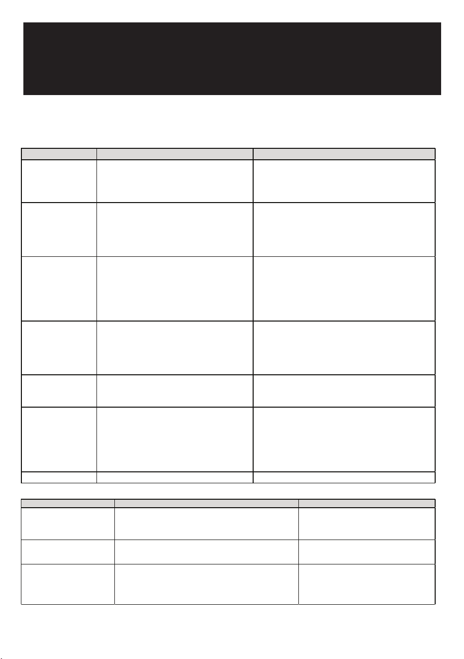
DESIGN 2 – For articulated hinge models
1. Pull the top decoration cover (3) upward and
remove it. Remove the cover caps (2) and then
remove the door by unscrewing the four screws
(1). Be careful to hold the door firmly after
2. removing the screws and place it on a padded
surface to avoid the risk of damage. Leave the
hinges open. (Figure 1)
3. Unscrew the four screws (4) to remove the top
and bottom articulated hinges. (Figure 2)
4. Pop out the cover caps on the left side of the
cabinet and use them to cover the screw holes
on the right-hand side.
5. Pull the top decoration cover (5) upward and remove it. Unscrew the two screws (6) and transfer the
retaining bracket (7) to the opposite side of the door. Refit the top decoration cover (5). (Figure 3)
6. Unscrew the screw (9) and transfer the bottom decoration cover (8) to the opposite side of the door.
(Figure 4)
7. Refit the articulated hinges to the opposite side of the door by using the four screws (3). (Repeat
step 2 in reverse.)
8. Refit the door to the opposite side. Then screw and tighten it after the door is leveled. (Repeat step 1
in reverse.)
DESIGN 3 – For panel ready models
1. Pull the top decoration cover (3) upward and
remove it. Remove the cover caps (2) and then
remove the door by unscrewing the four screws
(1). Be careful to hold the door firmly after
removing the screws and place it on a padded
surface to avoid the risk of damage. Leave the
hinges open. (Figure 1)
2. Unscrew the four screws (4) to remove the top
and bottom articulated hinges. (Figure 2)
3. Pop out the cover caps on the left side of the cabinet and use them to cover the screw holes on the
right-hand side.
4. Unscrew the two screws (5) and transfer the retaining bracket (6) to the opposite side of the door.
(Figure 3)
5. Refit the articulated hinges to the opposite side of the door by using the four screws (3). (Repeat
step 2 in reverse.)
6. Refit the door to the opposite side. Then screw and tighten it after the door is leveled. (Repeat step 1
in reverse.)
7. Refit the alternative top decoration cover included in the fittings on the top of door.
OVERLAY PANEL INSTALLATION INSTRUCTION
Door Panel Preparation
Depending on the model prepare the overlay panel to
the dimensions shown below. Then attach the handle
to the overlay panel by using the flat head screws and
drive the screws flush with the panel if needed.
NOTE:
H can be 28⅜" and 30". It depends on the actual product specification.
Weight of the overlay panel should not exceed 22 Lbs.
It is important to ensure that all drilled holes are drilled to the correct depth in order to
avoid splits in the wood when hardware is installed.
Drill the handle installation holes in the overlay panel according to the handle you are
planning to use. If reusing the handles came with the unit, drill two holes with holes
distance same as handle and diameter 5mm in the overlay panel.
use an extension cord with this appliance. However, if you must use an extension cord it is absolutely
necessary that it be a UL/CUL-listed, 3-wire grounding type appliance extension cord having a grounding
type plug and outlet and that the electrical rating of the cord be 115 volts and at least 10 amperes.
INSTALLING THE HANDLE
IMPORTANT: Do not overtighten the screws & do not use
power tools to install the handle.
DESIGN 1 –
Locate the handle (2) over the mounting stubs (1) of the
door and tighten the grub screws (3) with an Allen key to
secure the handle.
DESIGN 2 –
Remove the door gasket on the side you wish to install the
handle - you can see two designated holes for handle
installation.
Install the handle (3) tightly as shown above with two
screws (1) and flat washers (2) provided.
Replace the door gasket.
REVERSING THE DOOR HINGE
It is possible to reverse the door on this appliance, if
required.
To do so, follow the steps below:
Note: All parts removed must be saved to do the reinstallation of the door.
DESIGN 1 – For standard hinge models
1. Remove the bottom hinge (1) by unscrewing the
two lock screws (2). Be careful to hold the door
firmly after removing the screws. (Fig. 1)
2. Gently pull down to remove the door (3) from the
right top hinge and place it on a padded surface
to avoid the risk of damage. Then remove the
right top hinge (3). (Fig. 2 & 3)
3. Pop out the cover caps on the left side of cabinet
and use them to cover the screw holes on the
right hand side.
4. Screw the alternative left top hinge (4), included
in the fittings, on the left hand side of cabinet.
(Fig. 3)
5. Relocate the door to the designated position. Then screw the bottom hinge assembly on the left
designated position and tighten it after the door is leveled.
NOTE: Make sure that the socket and ON/OFF switch are easily accessible after the appliance has been
installed.
BUILT-UNDER INSTRUCTIONS
Make sure your installation does not block the front ventilation grill. If the unit is fully integrated to be
installed for fitting kitchen, make sure that the ventilation gaps in the plinth are at least 300 square
centimeters and remove the ventilation grilles, so that warm air can disperse unhindered. Otherwise the
appliance has to work harder, resulting in an increase in electricity consumption.
NOTE: When pushing the appliance into the niche, make sure that the mains cable does not get trapped.
CAUTION
To ensure the proper functioning of the appliance, air vents should never be blocked or covered.
ELECTRICAL CONNECTION
Check that the voltage marked on the product corresponds with your supply voltage
WARNING
Improper use of the grounded plug can result in the risk of electrical shock. If the power cord is damaged,
have it replaced by a qualified electrician or an authorized service center.
This appliance should be properly grounded for your safety. The power cord of this appliance is equipped
with a three-prong plug which mates with standard three-prong wall outlets to minimize the possibility of
electrical shock.
Do not under any circumstances cut or remove the third (ground) prong from the power cord supplied.
For personal safety, this appliance must be properly grounded.
This appliance requires a standard 115/120 Volt AC ~ 60Hz three-prong grounded electrical outlet. Have
the wall outlet and circuit checked by a qualified electrician to make sure the outlet is properly grounded.
When a standard 2-prong wall outlet is encountered, it is your responsibility and obligation to have it
replaced with a properly grounded 3-prong wall outlet.
To prevent accidental injury, the cord should be secured behind the appliance and not left exposed or
dangling.
The appliance should always be plugged into its own individual electrical outlet which has a voltage
rating that matches the rating label on the appliance. This provides the best performance and also
prevents overloading house wiring circuits that could cause a fire hazard from overheating. Never unplug
the appliance by pulling on the power cord. Always grip the plug firmly and pull straight out from the
receptacle. Repair or replace immediately all power cords that have become frayed or otherwise
damaged. Do not use a cord that shows cracks or abrasion damage along its length or at either end.
When moving the appliance, be careful not to damage the power cord.
EXTENSION CORD
Because of potential safety hazards under certain conditions, it is strongly recommended that you do not
BEFORE USING YOUR APPLIANCE
- Remove all exterior and interior packing. Clean the interior surface with lukewarm water using a soft
cloth. The unit may have residual odors at first, they will disappear as the unit cools.
- IMPORTANT: Before connecting the icemachine to the power source, let it stand upright for
approximately 24 hours. This will reduce the possibility of a malfunction in the cooling system
caused by handling during transportation.
- The door on this appliance can be opened either the left or the right side. The unit is delivered with
the door opening on the left side. Should you wish to open the door from the right, follow the
instructions "Reversing the door hinge".
- Install the handle on the door.
- Sanitize the ice machine. All ice machines are factory-operated and adjusted before shipment.
Normally, new installations do not require any adjustment.
INSTALLATION OF YOUR APPLIANCE
WARNING
This appliance must be installed in accordance with all local codes and ordinances.
• The appliances are designed to be built-in or recessed or free-standing installation.
• This ice machine should be properly installed by qualified personnel.
• WARNING: Flammable Refrigerant Used. Appliance should be installed in accordance with the
Safety Standard for Refrigeration Systems, ANSI/ASHRAE 15.
• Place your ice machine on a floor that is even and strong enough to support it when it is fully loaded.
It is very important for the ice machine to be level in order to work properly. To level your unit, adjust
the front adjustable legs at the bottom of the unit.
• For freestanding installation, 5 inches (127mm) of space between the back and sides of the unit are
suggested, which allows the proper air circulation to cool the compressor and condenser for energy
saving. Even for built-in installation, it is a must to keep ¾" (5mm) space on each side and at the top
to ensure proper service access and efficient ventilation. Take care that the air vent at the front of
the appliance must never be covered or blocked in any way.
• Installation of the ice maker requires a cold water supply inlet of ¼-in. (6.35mm) soft copper tubing
with a shut-off valve.
• Locate the unit away from direct sunlight and sources of heat (stove, heater, radiator, etc.). Direct
sunlight may affect the acrylic coating and heat sources may increase electrical consumption.
Extreme cold ambient temperatures may also cause the unit not to perform properly.
• Avoid locating the unit in damp areas.
• Plug the unit into an exclusive, easily accessible and properly grounded wall outlet. Do not under any
circumstances cut or remove the third (ground) prong from the power cord. Any questions concern-
ing power and/or earthing should be directed towards a qualified electrician or an authorized
products service centre.
• The appliance must be installed to all electrical, plumbing, water and drain connections in
accordance with state and local codes.
• The equipment must be installed with adequate backflow protection to comply with applicable
federal, state and local codes.
• It is strongly recommended that a water filter be used. A filter, if it is of the proper type, can remove
taste and odors as well as particles. Some water is very hard, and softened water may result in
white, mushy cubes that stick together. Deionized water is not recommended.
Door Panel Installation
Attach the wood overlay panel (1) on the door (2) by using the four wood screws ST4x15 Type AB Philips
(3).
WATER SUPPLY AND DRAIN REQUIREMENTS
Prepare water supply line and drain before installation of your ice machine. Installation requires a 1/4" ID
copper cold water line and compression fitting (not supplied).
The ice machine IM50 is supplied with an automatic drain pump system. The ice machine IM30 is
supplied with a drain hose for gravity draining. Both drain methods require routing to an open site drain.
Do not connect directly to drain line as bacteria from drain line may contaminate the ice machine.
Make certain the hoses are not pinched or kinked or damaged during installation.
Check for leaks after connection.
WATER INLET LINES
CAUTION
Copper tubing is recommended for the water supply line. Water supply tubing made of 1/4" plastic is not
recommended since it greatly increases the potential for water leaks. Manufacturer will not be responsible
for any damage if plastic tubing is used for the supply line.
Follow these guidelines to install water inlet lines:
▪ Do not connect the ice machine to a hot water supply. Be sure all hot water restrictors installed for
other equipment are working. (Check valves on sink faucets, dishwashers, etc.)
▪ If water pressure exceeds the maximum recommended pressure (80 psi - 55 bar), obtain a water
pressure regulator.
▪ Install a water shut-off valve for the ice making water lines.
▪ Insulate the water inlet line to prevent condensation.
▪ Install tubing only in areas where temperatures will remain above freezing.
▪ Leave a coil of copper tubing to allow the ice maker to be pulled out of the cabinet or away from the
wall for service.
DRAIN CONNECTIONS (FACTORY SUPPLIED)
Follow these guidelines when installing drain lines to prevent drain water from flowing back into the ice
machine and storage bin:
▪ Drain lines must have a 1.5 inch drop per 5 feet of run (2.5 cm per meter), and must not create traps.
▪ The floor drain must be large enough to accommodate drainage from all drains.
▪ Drain pump discharge line must terminate at an open site drain.
▪ The maximum length of drain hose is 5 feet (1.5
m).
▪ The maximum rise of drain hose is 2.6 feet (0.8
m).
▪ Pour 3000ml of water into the ice storage bin to
check for leaks in the drainage system.
WATER SUPPLY AND DRAIN LINE
SIZING/CONNECTIONS
CAUTION
Plumbing must conform to state and local codes.
NOTE: If air temperature is less than 60°F (15.5°C), water
temperature must be equal to or greater than 50°F (10°C).
INSTALLATION PROCEDURE
1. Prepare the site by following the instructions under Electrical Connection and Water Supply and
Drain Requirements.
2. Remove ice machine from carton.
3. Inspect for damage.
4. Remove literature packet and drain hose from inside the ice machine.
5. Adjust leg levelers.
6. Reverse door if desired. See Reversing the Door Hinge.
7. Install drain hose to drain on back of ice machine and route to open site drain.
8. Use compression fitting to connect the Water Inlet on back of ice machine to the prepared 1/4" ID
cold water line.
9. Open the shut-off valve on the water line.
10. Connect electrical plug to grounded (three-prong), polarized outlet.
11. Place ice machine back in position and check leveling again. Make any necessary adjustments.
12. Prepare sanitizer solution and sanitize the ice machine according to Cleaning/Sanitizing the Ice
Making System.
13. At initial start-up, ice machine will need approximately 45 minutes to freeze.
INSTALLATION CHECK LIST
▪ Is the Ice Machine level?!
▪ Has all of the packing been removed?
▪ Have all of the electrical and water connections been made?
▪ Has the supply voltage been tested and checked against the rating on the nameplate?
▪ Is there proper clearance around the ice machine for air circulation?
▪ Has the ice machine been installed where ambient temperatures will remain in the range of 41° -
100°F (5° - 38°C)?
▪ Has the ice machine been installed where the incoming water temperature will remain in the range
of 41° - 90°F (5° - 32°C)?
▪ Has the water supply pressure been checked to ensure a minimum of 20 psig with a static pressure
not to exceed 80 psig?
▪ Is the ice machine drain line routed to an open site drain?
▪ Are all electrical leads free from contact with refrigeration lines and moving equipment?
▪ Has the ice machine and bin been sanitized?
▪ Is the ice machine plugged into a properly grounded, polarized receptacle?
▪ Have the water and drain connections been examined for leaks?
TROUBLESHOOTING
PROBLEM POSSIBLE CAUSE REMEDY
Ice machine will not
run
The appliance is not connected to a power
supply. The appliance is turned off or a blown
fuse. The ice storage bin is full of ice.
Switch on the appliance. Connect the appliance. Switch
on circuit breaker or replace fuse. Remove some ice
cubes. Be sure the bin thermistor holder is free of ice.
Ice machine runs and
no ice is produced
No water to ice machine or too little water
inside the water trough. Incorrect incoming
water pressure. Spray nozzles blocked with
mineral buildup. Ambient temperature is too
high or low.
Correct water supply. Water pressure must be 20-80
psi (1.4 bar - 5.5 bar). Clean and sanitize the ice
machine. Ambient temperature must be between 50°F
and 110°F (10°C and 43°C). Call for service.
Freeze cycle is long -
Low ice production
Refrigerating system failure. Water
temperature is too high.
Connect to a cold water supply, verify check valves in
faucets and other equipment are functioning correctly.
Clean condenser. Air temperature must not exceed
110°F (43°C). Remove the water inlet and clean filter
screen. Water inlet valve must be replaced, call for
service. Call for service.
Ice quality is poor -
cubes are shallow,
incomplete or white.
Dirty condenser. High air temperature
entering condenser. Water inlet filter screen is
dirty.
Clean and sanitize the ice machine. Contact a qualified
service company to test the quality of the incoming
water and make appropriate water filter
recommendations. Remove the filter and clean the ice
screen.
The water doesn't
feed in after the
machine starts.
Water filter screen is dirty. Water is not
accurately sprayed from the nozzle to the
center of the evaporator buckets.
Clean the filter by machine - the nozzle may be
clogged with a foreign object. Turn on the water
supply tap.
Water leaks from ice
storage bin
The water supply pipe is turned off. The water
supply tap is not properly connected. The
drain hole below the ice storage bin is
blocked. The drain hose is kinked or
improperly placed higher than the floor of the
ice storage bin.
Reconnect the water supply pipe. Check the drain
hose to be sure water can be drained out unhindered.
Vibrations. The appliance is not properly level. Adjust the appliance with the levelable feet.
PRO BLEM POSSIBLE CAUSE RE MEDY
The appliance seems to make too
much noise.
The rattling noise may come from the flow of the refrigerant, which is
n
ormal. As each cycle ends, you may hear gurgling sounds caused by the
f
low of refrigerant in your appliance. During the freeze cycle, you may
hear the sound of ice cubes, which is normal.
Adjust the appliance level with the adjustable feet and
remove some ice.
The door will not close properly.
The appliance is not properly level. Is there ice between the ice chute and
t
he water shutter? The appliance is not properly level. The door was
reversed and not properly installed. The gasket is dirty.
Level the appliance with the adjustable feet. Check the
door hinge and reassemble correctly. Clean the door
gasket.
Display “E1”, “E2”, “E3”, “E4”, “E5”,
“E6”, “E7”, “E8” or “HP”.
“E1” or “E2” indicates that the ambient air temperature sensor is failed.
“
E3” or “E4” indicates that the sensor in the suction pipe is failed. “E5” or
“
E6” indicates that the sensor in the bin thermistor holder is failed. “E7”
i
ndicates the drainage failure. “E8” indicates the water inlet failure. “HP”
indicates the high pressure protection.
Try resetting the controls by disconnecting power to
the unit for 5 minutes, then reconnect. If error code
returns, problem cannot be resolved by user. Call for
service.
PROBLEMS WITH YOUR APPLIANCE
You can solve many common problems easily, saving you the cost of a possible service call.
Try the suggestions below to see if you can solve the problem before calling customer service.
21

DESIGN 2 – For articulated hinge models
1. Pull the top decoration cover (3) upward and
remove it. Remove the cover caps (2) and then
remove the door by unscrewing the four screws
(1). Be careful to hold the door firmly after
2. removing the screws and place it on a padded
surface to avoid the risk of damage. Leave the
hinges open. (Figure 1)
3. Unscrew the four screws (4) to remove the top
and bottom articulated hinges. (Figure 2)
4. Pop out the cover caps on the left side of the
cabinet and use them to cover the screw holes
on the right-hand side.
5. Pull the top decoration cover (5) upward and remove it. Unscrew the two screws (6) and transfer the
retaining bracket (7) to the opposite side of the door. Refit the top decoration cover (5). (Figure 3)
6. Unscrew the screw (9) and transfer the bottom decoration cover (8) to the opposite side of the door.
(Figure 4)
7. Refit the articulated hinges to the opposite side of the door by using the four screws (3). (Repeat
step 2 in reverse.)
8. Refit the door to the opposite side. Then screw and tighten it after the door is leveled. (Repeat step 1
in reverse.)
DESIGN 3 – For panel ready models
1. Pull the top decoration cover (3) upward and
remove it. Remove the cover caps (2) and then
remove the door by unscrewing the four screws
(1). Be careful to hold the door firmly after
removing the screws and place it on a padded
surface to avoid the risk of damage. Leave the
hinges open. (Figure 1)
2. Unscrew the four screws (4) to remove the top
and bottom articulated hinges. (Figure 2)
3. Pop out the cover caps on the left side of the cabinet and use them to cover the screw holes on the
right-hand side.
4. Unscrew the two screws (5) and transfer the retaining bracket (6) to the opposite side of the door.
(Figure 3)
5. Refit the articulated hinges to the opposite side of the door by using the four screws (3). (Repeat
step 2 in reverse.)
6. Refit the door to the opposite side. Then screw and tighten it after the door is leveled. (Repeat step 1
in reverse.)
7. Refit the alternative top decoration cover included in the fittings on the top of door.
OVERLAY PANEL INSTALLATION INSTRUCTION
Door Panel Preparation
Depending on the model prepare the overlay panel to
the dimensions shown below. Then attach the handle
to the overlay panel by using the flat head screws and
drive the screws flush with the panel if needed.
NOTE:
H can be 28⅜" and 30". It depends on the actual product specification.
Weight of the overlay panel should not exceed 22 Lbs.
It is important to ensure that all drilled holes are drilled to the correct depth in order to
avoid splits in the wood when hardware is installed.
Drill the handle installation holes in the overlay panel according to the handle you are
planning to use. If reusing the handles came with the unit, drill two holes with holes
distance same as handle and diameter 5mm in the overlay panel.
use an extension cord with this appliance. However, if you must use an extension cord it is absolutely
necessary that it be a UL/CUL-listed, 3-wire grounding type appliance extension cord having a grounding
type plug and outlet and that the electrical rating of the cord be 115 volts and at least 10 amperes.
INSTALLING THE HANDLE
IMPORTANT: Do not overtighten the screws & do not use
power tools to install the handle.
DESIGN 1 –
Locate the handle (2) over the mounting stubs (1) of the
door and tighten the grub screws (3) with an Allen key to
secure the handle.
DESIGN 2 –
Remove the door gasket on the side you wish to install the
handle - you can see two designated holes for handle
installation.
Install the handle (3) tightly as shown above with two
screws (1) and flat washers (2) provided.
Replace the door gasket.
REVERSING THE DOOR HINGE
It is possible to reverse the door on this appliance, if
required.
To do so, follow the steps below:
Note: All parts removed must be saved to do the reinstallation of the door.
DESIGN 1 – For standard hinge models
1. Remove the bottom hinge (1) by unscrewing the
two lock screws (2). Be careful to hold the door
firmly after removing the screws. (Fig. 1)
2. Gently pull down to remove the door (3) from the
right top hinge and place it on a padded surface
to avoid the risk of damage. Then remove the
right top hinge (3). (Fig. 2 & 3)
3. Pop out the cover caps on the left side of cabinet
and use them to cover the screw holes on the
right hand side.
4. Screw the alternative left top hinge (4), included
in the fittings, on the left hand side of cabinet.
(Fig. 3)
5. Relocate the door to the designated position. Then screw the bottom hinge assembly on the left
designated position and tighten it after the door is leveled.
NOTE: Make sure that the socket and ON/OFF switch are easily accessible after the appliance has been
installed.
BUILT-UNDER INSTRUCTIONS
Make sure your installation does not block the front ventilation grill. If the unit is fully integrated to be
installed for fitting kitchen, make sure that the ventilation gaps in the plinth are at least 300 square
centimeters and remove the ventilation grilles, so that warm air can disperse unhindered. Otherwise the
appliance has to work harder, resulting in an increase in electricity consumption.
NOTE: When pushing the appliance into the niche, make sure that the mains cable does not get trapped.
CAUTION
To ensure the proper functioning of the appliance, air vents should never be blocked or covered.
ELECTRICAL CONNECTION
Check that the voltage marked on the product corresponds with your supply voltage
WARNING
Improper use of the grounded plug can result in the risk of electrical shock. If the power cord is damaged,
have it replaced by a qualified electrician or an authorized service center.
This appliance should be properly grounded for your safety. The power cord of this appliance is equipped
with a three-prong plug which mates with standard three-prong wall outlets to minimize the possibility of
electrical shock.
Do not under any circumstances cut or remove the third (ground) prong from the power cord supplied.
For personal safety, this appliance must be properly grounded.
This appliance requires a standard 115/120 Volt AC ~ 60Hz three-prong grounded electrical outlet. Have
the wall outlet and circuit checked by a qualified electrician to make sure the outlet is properly grounded.
When a standard 2-prong wall outlet is encountered, it is your responsibility and obligation to have it
replaced with a properly grounded 3-prong wall outlet.
To prevent accidental injury, the cord should be secured behind the appliance and not left exposed or
dangling.
The appliance should always be plugged into its own individual electrical outlet which has a voltage
rating that matches the rating label on the appliance. This provides the best performance and also
prevents overloading house wiring circuits that could cause a fire hazard from overheating. Never unplug
the appliance by pulling on the power cord. Always grip the plug firmly and pull straight out from the
receptacle. Repair or replace immediately all power cords that have become frayed or otherwise
damaged. Do not use a cord that shows cracks or abrasion damage along its length or at either end.
When moving the appliance, be careful not to damage the power cord.
EXTENSION CORD
Because of potential safety hazards under certain conditions, it is strongly recommended that you do not
BEFORE USING YOUR APPLIANCE
- Remove all exterior and interior packing. Clean the interior surface with lukewarm water using a soft
cloth. The unit may have residual odors at first, they will disappear as the unit cools.
- IMPORTANT: Before connecting the icemachine to the power source, let it stand upright for
approximately 24 hours. This will reduce the possibility of a malfunction in the cooling system
caused by handling during transportation.
- The door on this appliance can be opened either the left or the right side. The unit is delivered with
the door opening on the left side. Should you wish to open the door from the right, follow the
instructions "Reversing the door hinge".
- Install the handle on the door.
- Sanitize the ice machine. All ice machines are factory-operated and adjusted before shipment.
Normally, new installations do not require any adjustment.
INSTALLATION OF YOUR APPLIANCE
WARNING
This appliance must be installed in accordance with all local codes and ordinances.
• The appliances are designed to be built-in or recessed or free-standing installation.
• This ice machine should be properly installed by qualified personnel.
• WARNING: Flammable Refrigerant Used. Appliance should be installed in accordance with the
Safety Standard for Refrigeration Systems, ANSI/ASHRAE 15.
• Place your ice machine on a floor that is even and strong enough to support it when it is fully loaded.
It is very important for the ice machine to be level in order to work properly. To level your unit, adjust
the front adjustable legs at the bottom of the unit.
• For freestanding installation, 5 inches (127mm) of space between the back and sides of the unit are
suggested, which allows the proper air circulation to cool the compressor and condenser for energy
saving. Even for built-in installation, it is a must to keep ¾" (5mm) space on each side and at the top
to ensure proper service access and efficient ventilation. Take care that the air vent at the front of
the appliance must never be covered or blocked in any way.
• Installation of the ice maker requires a cold water supply inlet of ¼-in. (6.35mm) soft copper tubing
with a shut-off valve.
• Locate the unit away from direct sunlight and sources of heat (stove, heater, radiator, etc.). Direct
sunlight may affect the acrylic coating and heat sources may increase electrical consumption.
Extreme cold ambient temperatures may also cause the unit not to perform properly.
• Avoid locating the unit in damp areas.
• Plug the unit into an exclusive, easily accessible and properly grounded wall outlet. Do not under any
circumstances cut or remove the third (ground) prong from the power cord. Any questions concern-
ing power and/or earthing should be directed towards a qualified electrician or an authorized
products service centre.
• The appliance must be installed to all electrical, plumbing, water and drain connections in
accordance with state and local codes.
• The equipment must be installed with adequate backflow protection to comply with applicable
federal, state and local codes.
• It is strongly recommended that a water filter be used. A filter, if it is of the proper type, can remove
taste and odors as well as particles. Some water is very hard, and softened water may result in
white, mushy cubes that stick together. Deionized water is not recommended.
Door Panel Installation
Attach the wood overlay panel (1) on the door (2) by using the four wood screws ST4x15 Type AB Philips
(3).
WATER SUPPLY AND DRAIN REQUIREMENTS
Prepare water supply line and drain before installation of your ice machine. Installation requires a 1/4" ID
copper cold water line and compression fitting (not supplied).
The ice machine IM50 is supplied with an automatic drain pump system. The ice machine IM30 is
supplied with a drain hose for gravity draining. Both drain methods require routing to an open site drain.
Do not connect directly to drain line as bacteria from drain line may contaminate the ice machine.
Make certain the hoses are not pinched or kinked or damaged during installation.
Check for leaks after connection.
WATER INLET LINES
CAUTION
Copper tubing is recommended for the water supply line. Water supply tubing made of 1/4" plastic is not
recommended since it greatly increases the potential for water leaks. Manufacturer will not be responsible
for any damage if plastic tubing is used for the supply line.
Follow these guidelines to install water inlet lines:
▪ Do not connect the ice machine to a hot water supply. Be sure all hot water restrictors installed for
other equipment are working. (Check valves on sink faucets, dishwashers, etc.)
▪ If water pressure exceeds the maximum recommended pressure (80 psi - 55 bar), obtain a water
pressure regulator.
▪ Install a water shut-off valve for the ice making water lines.
▪ Insulate the water inlet line to prevent condensation.
▪ Install tubing only in areas where temperatures will remain above freezing.
▪ Leave a coil of copper tubing to allow the ice maker to be pulled out of the cabinet or away from the
wall for service.
DRAIN CONNECTIONS (FACTORY SUPPLIED)
Follow these guidelines when installing drain lines to prevent drain water from flowing back into the ice
machine and storage bin:
▪ Drain lines must have a 1.5 inch drop per 5 feet of run (2.5 cm per meter), and must not create traps.
▪ The floor drain must be large enough to accommodate drainage from all drains.
▪ Drain pump discharge line must terminate at an open site drain.
▪ The maximum length of drain hose is 5 feet (1.5
m).
▪ The maximum rise of drain hose is 2.6 feet (0.8
m).
▪ Pour 3000ml of water into the ice storage bin to
check for leaks in the drainage system.
WATER SUPPLY AND DRAIN LINE
SIZING/CONNECTIONS
CAUTION
Plumbing must conform to state and local codes.
NOTE: If air temperature is less than 60°F (15.5°C), water
temperature must be equal to or greater than 50°F (10°C).
INSTALLATION PROCEDURE
1. Prepare the site by following the instructions under Electrical Connection and Water Supply and
Drain Requirements.
2. Remove ice machine from carton.
3. Inspect for damage.
4. Remove literature packet and drain hose from inside the ice machine.
5. Adjust leg levelers.
6. Reverse door if desired. See Reversing the Door Hinge.
7. Install drain hose to drain on back of ice machine and route to open site drain.
8. Use compression fitting to connect the Water Inlet on back of ice machine to the prepared 1/4" ID
cold water line.
9. Open the shut-off valve on the water line.
10. Connect electrical plug to grounded (three-prong), polarized outlet.
11. Place ice machine back in position and check leveling again. Make any necessary adjustments.
12. Prepare sanitizer solution and sanitize the ice machine according to Cleaning/Sanitizing the Ice
Making System.
13. At initial start-up, ice machine will need approximately 45 minutes to freeze.
INSTALLATION CHECK LIST
▪ Is the Ice Machine level?!
▪ Has all of the packing been removed?
▪ Have all of the electrical and water connections been made?
▪ Has the supply voltage been tested and checked against the rating on the nameplate?
▪ Is there proper clearance around the ice machine for air circulation?
▪ Has the ice machine been installed where ambient temperatures will remain in the range of 41° -
100°F (5° - 38°C)?
▪ Has the ice machine been installed where the incoming water temperature will remain in the range
of 41° - 90°F (5° - 32°C)?
▪ Has the water supply pressure been checked to ensure a minimum of 20 psig with a static pressure
not to exceed 80 psig?
▪ Is the ice machine drain line routed to an open site drain?
▪ Are all electrical leads free from contact with refrigeration lines and moving equipment?
▪ Has the ice machine and bin been sanitized?
▪ Is the ice machine plugged into a properly grounded, polarized receptacle?
▪ Have the water and drain connections been examined for leaks?
LIMITED WARRANTY
Koolmore Supply, Inc. extends a limited warranty to the original purchaser, guaranteeing that this Koolmore
product is free from manufacturing defects in material or workmanship for one year from the date of
purchase.
Should you discover any such defect within the warranty period, Koolmore Supply, Inc., reserves the right to
repair or replace the product without charge, or to cover the cost of replacement parts and repair labor needed
to correct defects present at the time of purchase or resulting from regular usage, when the appliance has been
installed, operated, and maintained as per the instructions provided.
At its sole discretion, Koolmore Supply Inc. may decide to replace the product. In such an event, your replace-
ment appliance will carry the warranty for the remaining term of the original unit's warranty period.
This warranty is valid exclusively to the original purchaser of the product and only applicable within the United
States. The warranty commences from the date of original consumer purchase. Proof of the original purchase
date will be required to obtain service under this warranty.
Under this limited warranty, your sole and exclusive remedy will be product repair, as outlined above. All
services must be provided by a Koolmore-designated service company.
To claim warranty or request repair service:
Email [email protected]. Please include your name, address, phone number, warranty repair request,
and a copy of your proof of purchase receipt. Alternatively, visit koolmore.com and use the contact us page. A
Koolmore customer service representative will promptly arrange service for your appliance.
We thank you for choosing Koolmore.
WARRANTY EXCLUSIONS
This limited warranty will not cover:
1. Failure of the product to perform during power failures or interruptions,
or due to inadequate electrical service.
2. Damage incurred during transportation or handling.
3. Damage caused by accidents, vermin, lightning, winds, fire, floods, or acts of God.
4. Damage resulting from accidents, alterations, misuse, abuse, improper installation, repair, or
maintenance. This includes using any external device that alters or converts the voltage or
frequency of electricity.
5. Unauthorized product modifications, repairs by unauthorized centers, or use of non-approved
replacement parts.
6. Abnormal cleaning and maintenance not aligned with the user's manual.
7. Use of incompatible accessories or components.
8. Any costs associated with repairs or replacements under these excluded circumstances shall be
the responsibility of the consumer.
WARRANTY
22

DESIGN 2 – For articulated hinge models
1. Pull the top decoration cover (3) upward and
remove it. Remove the cover caps (2) and then
remove the door by unscrewing the four screws
(1). Be careful to hold the door firmly after
2. removing the screws and place it on a padded
surface to avoid the risk of damage. Leave the
hinges open. (Figure 1)
3. Unscrew the four screws (4) to remove the top
and bottom articulated hinges. (Figure 2)
4. Pop out the cover caps on the left side of the
cabinet and use them to cover the screw holes
on the right-hand side.
5. Pull the top decoration cover (5) upward and remove it. Unscrew the two screws (6) and transfer the
retaining bracket (7) to the opposite side of the door. Refit the top decoration cover (5). (Figure 3)
6. Unscrew the screw (9) and transfer the bottom decoration cover (8) to the opposite side of the door.
(Figure 4)
7. Refit the articulated hinges to the opposite side of the door by using the four screws (3). (Repeat
step 2 in reverse.)
8. Refit the door to the opposite side. Then screw and tighten it after the door is leveled. (Repeat step 1
in reverse.)
DESIGN 3 – For panel ready models
1. Pull the top decoration cover (3) upward and
remove it. Remove the cover caps (2) and then
remove the door by unscrewing the four screws
(1). Be careful to hold the door firmly after
removing the screws and place it on a padded
surface to avoid the risk of damage. Leave the
hinges open. (Figure 1)
2. Unscrew the four screws (4) to remove the top
and bottom articulated hinges. (Figure 2)
3. Pop out the cover caps on the left side of the cabinet and use them to cover the screw holes on the
right-hand side.
4. Unscrew the two screws (5) and transfer the retaining bracket (6) to the opposite side of the door.
(Figure 3)
5. Refit the articulated hinges to the opposite side of the door by using the four screws (3). (Repeat
step 2 in reverse.)
6. Refit the door to the opposite side. Then screw and tighten it after the door is leveled. (Repeat step 1
in reverse.)
7. Refit the alternative top decoration cover included in the fittings on the top of door.
OVERLAY PANEL INSTALLATION INSTRUCTION
Door Panel Preparation
Depending on the model prepare the overlay panel to
the dimensions shown below. Then attach the handle
to the overlay panel by using the flat head screws and
drive the screws flush with the panel if needed.
NOTE:
H can be 28⅜" and 30". It depends on the actual product specification.
Weight of the overlay panel should not exceed 22 Lbs.
It is important to ensure that all drilled holes are drilled to the correct depth in order to
avoid splits in the wood when hardware is installed.
Drill the handle installation holes in the overlay panel according to the handle you are
planning to use. If reusing the handles came with the unit, drill two holes with holes
distance same as handle and diameter 5mm in the overlay panel.
use an extension cord with this appliance. However, if you must use an extension cord it is absolutely
necessary that it be a UL/CUL-listed, 3-wire grounding type appliance extension cord having a grounding
type plug and outlet and that the electrical rating of the cord be 115 volts and at least 10 amperes.
INSTALLING THE HANDLE
IMPORTANT: Do not overtighten the screws & do not use
power tools to install the handle.
DESIGN 1 –
Locate the handle (2) over the mounting stubs (1) of the
door and tighten the grub screws (3) with an Allen key to
secure the handle.
DESIGN 2 –
Remove the door gasket on the side you wish to install the
handle - you can see two designated holes for handle
installation.
Install the handle (3) tightly as shown above with two
screws (1) and flat washers (2) provided.
Replace the door gasket.
REVERSING THE DOOR HINGE
It is possible to reverse the door on this appliance, if
required.
To do so, follow the steps below:
Note: All parts removed must be saved to do the reinstallation of the door.
DESIGN 1 – For standard hinge models
1. Remove the bottom hinge (1) by unscrewing the
two lock screws (2). Be careful to hold the door
firmly after removing the screws. (Fig. 1)
2. Gently pull down to remove the door (3) from the
right top hinge and place it on a padded surface
to avoid the risk of damage. Then remove the
right top hinge (3). (Fig. 2 & 3)
3. Pop out the cover caps on the left side of cabinet
and use them to cover the screw holes on the
right hand side.
4. Screw the alternative left top hinge (4), included
in the fittings, on the left hand side of cabinet.
(Fig. 3)
5. Relocate the door to the designated position. Then screw the bottom hinge assembly on the left
designated position and tighten it after the door is leveled.
NOTE: Make sure that the socket and ON/OFF switch are easily accessible after the appliance has been
installed.
BUILT-UNDER INSTRUCTIONS
Make sure your installation does not block the front ventilation grill. If the unit is fully integrated to be
installed for fitting kitchen, make sure that the ventilation gaps in the plinth are at least 300 square
centimeters and remove the ventilation grilles, so that warm air can disperse unhindered. Otherwise the
appliance has to work harder, resulting in an increase in electricity consumption.
NOTE: When pushing the appliance into the niche, make sure that the mains cable does not get trapped.
CAUTION
To ensure the proper functioning of the appliance, air vents should never be blocked or covered.
ELECTRICAL CONNECTION
Check that the voltage marked on the product corresponds with your supply voltage
WARNING
Improper use of the grounded plug can result in the risk of electrical shock. If the power cord is damaged,
have it replaced by a qualified electrician or an authorized service center.
This appliance should be properly grounded for your safety. The power cord of this appliance is equipped
with a three-prong plug which mates with standard three-prong wall outlets to minimize the possibility of
electrical shock.
Do not under any circumstances cut or remove the third (ground) prong from the power cord supplied.
For personal safety, this appliance must be properly grounded.
This appliance requires a standard 115/120 Volt AC ~ 60Hz three-prong grounded electrical outlet. Have
the wall outlet and circuit checked by a qualified electrician to make sure the outlet is properly grounded.
When a standard 2-prong wall outlet is encountered, it is your responsibility and obligation to have it
replaced with a properly grounded 3-prong wall outlet.
To prevent accidental injury, the cord should be secured behind the appliance and not left exposed or
dangling.
The appliance should always be plugged into its own individual electrical outlet which has a voltage
rating that matches the rating label on the appliance. This provides the best performance and also
prevents overloading house wiring circuits that could cause a fire hazard from overheating. Never unplug
the appliance by pulling on the power cord. Always grip the plug firmly and pull straight out from the
receptacle. Repair or replace immediately all power cords that have become frayed or otherwise
damaged. Do not use a cord that shows cracks or abrasion damage along its length or at either end.
When moving the appliance, be careful not to damage the power cord.
EXTENSION CORD
Because of potential safety hazards under certain conditions, it is strongly recommended that you do not
BEFORE USING YOUR APPLIANCE
- Remove all exterior and interior packing. Clean the interior surface with lukewarm water using a soft
cloth. The unit may have residual odors at first, they will disappear as the unit cools.
- IMPORTANT: Before connecting the icemachine to the power source, let it stand upright for
approximately 24 hours. This will reduce the possibility of a malfunction in the cooling system
caused by handling during transportation.
- The door on this appliance can be opened either the left or the right side. The unit is delivered with
the door opening on the left side. Should you wish to open the door from the right, follow the
instructions "Reversing the door hinge".
- Install the handle on the door.
- Sanitize the ice machine. All ice machines are factory-operated and adjusted before shipment.
Normally, new installations do not require any adjustment.
INSTALLATION OF YOUR APPLIANCE
WARNING
This appliance must be installed in accordance with all local codes and ordinances.
• The appliances are designed to be built-in or recessed or free-standing installation.
• This ice machine should be properly installed by qualified personnel.
• WARNING: Flammable Refrigerant Used. Appliance should be installed in accordance with the
Safety Standard for Refrigeration Systems, ANSI/ASHRAE 15.
• Place your ice machine on a floor that is even and strong enough to support it when it is fully loaded.
It is very important for the ice machine to be level in order to work properly. To level your unit, adjust
the front adjustable legs at the bottom of the unit.
• For freestanding installation, 5 inches (127mm) of space between the back and sides of the unit are
suggested, which allows the proper air circulation to cool the compressor and condenser for energy
saving. Even for built-in installation, it is a must to keep ¾" (5mm) space on each side and at the top
to ensure proper service access and efficient ventilation. Take care that the air vent at the front of
the appliance must never be covered or blocked in any way.
• Installation of the ice maker requires a cold water supply inlet of ¼-in. (6.35mm) soft copper tubing
with a shut-off valve.
• Locate the unit away from direct sunlight and sources of heat (stove, heater, radiator, etc.). Direct
sunlight may affect the acrylic coating and heat sources may increase electrical consumption.
Extreme cold ambient temperatures may also cause the unit not to perform properly.
• Avoid locating the unit in damp areas.
• Plug the unit into an exclusive, easily accessible and properly grounded wall outlet. Do not under any
circumstances cut or remove the third (ground) prong from the power cord. Any questions concern-
ing power and/or earthing should be directed towards a qualified electrician or an authorized
products service centre.
• The appliance must be installed to all electrical, plumbing, water and drain connections in
accordance with state and local codes.
• The equipment must be installed with adequate backflow protection to comply with applicable
federal, state and local codes.
• It is strongly recommended that a water filter be used. A filter, if it is of the proper type, can remove
taste and odors as well as particles. Some water is very hard, and softened water may result in
white, mushy cubes that stick together. Deionized water is not recommended.
Door Panel Installation
Attach the wood overlay panel (1) on the door (2) by using the four wood screws ST4x15 Type AB Philips
(3).
WATER SUPPLY AND DRAIN REQUIREMENTS
Prepare water supply line and drain before installation of your ice machine. Installation requires a 1/4" ID
copper cold water line and compression fitting (not supplied).
The ice machine IM50 is supplied with an automatic drain pump system. The ice machine IM30 is
supplied with a drain hose for gravity draining. Both drain methods require routing to an open site drain.
Do not connect directly to drain line as bacteria from drain line may contaminate the ice machine.
Make certain the hoses are not pinched or kinked or damaged during installation.
Check for leaks after connection.
WATER INLET LINES
CAUTION
Copper tubing is recommended for the water supply line. Water supply tubing made of 1/4" plastic is not
recommended since it greatly increases the potential for water leaks. Manufacturer will not be responsible
for any damage if plastic tubing is used for the supply line.
Follow these guidelines to install water inlet lines:
▪ Do not connect the ice machine to a hot water supply. Be sure all hot water restrictors installed for
other equipment are working. (Check valves on sink faucets, dishwashers, etc.)
▪ If water pressure exceeds the maximum recommended pressure (80 psi - 55 bar), obtain a water
pressure regulator.
▪ Install a water shut-off valve for the ice making water lines.
▪ Insulate the water inlet line to prevent condensation.
▪ Install tubing only in areas where temperatures will remain above freezing.
▪ Leave a coil of copper tubing to allow the ice maker to be pulled out of the cabinet or away from the
wall for service.
DRAIN CONNECTIONS (FACTORY SUPPLIED)
Follow these guidelines when installing drain lines to prevent drain water from flowing back into the ice
machine and storage bin:
▪ Drain lines must have a 1.5 inch drop per 5 feet of run (2.5 cm per meter), and must not create traps.
▪ The floor drain must be large enough to accommodate drainage from all drains.
▪ Drain pump discharge line must terminate at an open site drain.
▪ The maximum length of drain hose is 5 feet (1.5
m).
▪ The maximum rise of drain hose is 2.6 feet (0.8
m).
▪ Pour 3000ml of water into the ice storage bin to
check for leaks in the drainage system.
WATER SUPPLY AND DRAIN LINE
SIZING/CONNECTIONS
CAUTION
Plumbing must conform to state and local codes.
NOTE: If air temperature is less than 60°F (15.5°C), water
temperature must be equal to or greater than 50°F (10°C).
INSTALLATION PROCEDURE
1. Prepare the site by following the instructions under Electrical Connection and Water Supply and
Drain Requirements.
2. Remove ice machine from carton.
3. Inspect for damage.
4. Remove literature packet and drain hose from inside the ice machine.
5. Adjust leg levelers.
6. Reverse door if desired. See Reversing the Door Hinge.
7. Install drain hose to drain on back of ice machine and route to open site drain.
8. Use compression fitting to connect the Water Inlet on back of ice machine to the prepared 1/4" ID
cold water line.
9. Open the shut-off valve on the water line.
10. Connect electrical plug to grounded (three-prong), polarized outlet.
11. Place ice machine back in position and check leveling again. Make any necessary adjustments.
12. Prepare sanitizer solution and sanitize the ice machine according to Cleaning/Sanitizing the Ice
Making System.
13. At initial start-up, ice machine will need approximately 45 minutes to freeze.
INSTALLATION CHECK LIST
▪ Is the Ice Machine level?!
▪ Has all of the packing been removed?
▪ Have all of the electrical and water connections been made?
▪ Has the supply voltage been tested and checked against the rating on the nameplate?
▪ Is there proper clearance around the ice machine for air circulation?
▪ Has the ice machine been installed where ambient temperatures will remain in the range of 41° -
100°F (5° - 38°C)?
▪ Has the ice machine been installed where the incoming water temperature will remain in the range
of 41° - 90°F (5° - 32°C)?
▪ Has the water supply pressure been checked to ensure a minimum of 20 psig with a static pressure
not to exceed 80 psig?
▪ Is the ice machine drain line routed to an open site drain?
▪ Are all electrical leads free from contact with refrigeration lines and moving equipment?
▪ Has the ice machine and bin been sanitized?
▪ Is the ice machine plugged into a properly grounded, polarized receptacle?
▪ Have the water and drain connections been examined for leaks?