Installation
Use & Care
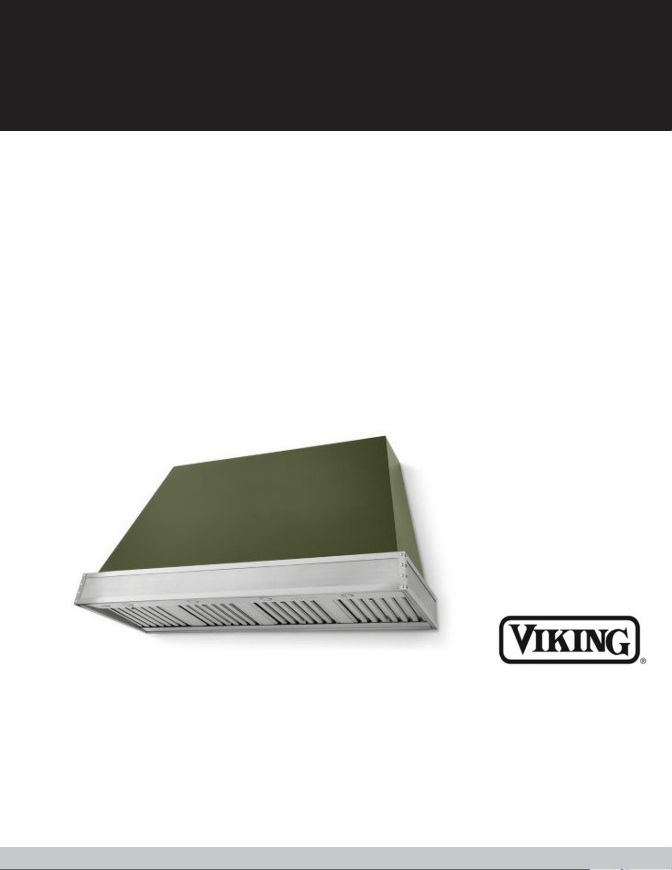
Tuscany Hoods
TVHW3630
TVHW4830
TVHW6630
TVHW3642
TVHW4842
TVHW6642
TVHW3654
TVHW4854
TVHW6654
MANUAL
1
I N D E X
NEVER PICK UP A FLAMING
PAN You may be burned.
DO NOT USE WATER Including wet
dishcloths or towels; a violent steam
explosion will result.
Warnings ................................................................................................................................................................. 1
Venting Requirements ............................................................................................................................................ 2
Electrical Requirements........................................................................................................................................ 2-3
Recommendations and Suggestions....................................................................................................................... 4
Dimensions of Hoods/Line Drawings...................................................................................................................... 5
Top/Rear Venting Options ..................................................................................................................................... 6
Electrical Connections ............................................................................................................................................ 7
Operational Controls............................................................................................................................................... 7
Best Practices for Installation................................................................................................................................... 9
Use an extinguisher only if:
You know you have a Class ABC extinguisher, and you
already know how to operate it.
The fire is small and contained in the area where it started.
The fire department is being called.
You can fight the fire with your back to an exit.
ALL WALL AND FLOOR OPENINGS WHERE THE RANGEHOOD IS INSTALLED MUST BE SEALED. This range
hood requires at least 24" of clearance between the bottom of the range hood and the cooking surface or
countertop. Consult the cooktop or range installation instructions given by the manufacturer before making any
cutouts.
The Installer must leave these instructions with the homeowner. The homeowner must keep these instructions
for future reference and for local electrical inspectors' use.
READ THESE INSTRUCTIONS BEFORE YOU START INSTALLING THIS RANGEHOOD
W A R N I N G S
PLEASE READ, FOLLOW, AND SAVE THESE INSTRUCTIONS
TO REDUCE THE RISK OF A RANGE TOP
GREASE FIRE - Never leave surface units
unattended at high settings. Boilovers cause
smoking and greasy spillovers that may ignite.
Heat oils slowly on low or medium setting.
Always turn hood ON when cooking at high heat or when flambeing food (i.e. Crepes Suzette, Cherries
Jubilee, Peppercorn Beef Flambe). Clean ventilating fans frequently. Grease should not be allowed to
accumulate on fan or filter. Use proper pan size. Always use cookware appropriate for the size of the
surface element.
TO REDUCE THE RISK OF INJURY TO PERSONS IN THE
EVENT OF A RANGE TOP GREASE FIRE - Smother
flames with a close-fitting lid, cookie sheet, or metal
tray, then turn off the burner. Be careful to prevent
burns. If the flames do not go out immediately
EVACUATE AND CALL THE FIRE DEPARTMENT.
WARNING:
WARNING:
Care......................................................................................................................................................................... 8
2
V E N T I N G R E Q U I R E M E N T S
E L E C T R I C A L R E Q U I R E M E N T S
DO Venting system MUST terminate outside the home.
DO NOT terminate the ductwork in an attic or other enclosed
space.
DO NOT use laundry-type wall caps.
Flexible-type ductwork is NOT recommended.
DO NOT obstruct the flow of combustion and ventilation air.
Failure to follow venting requirements may result in a fire.
A 120 volt, 60 Hz AC-only electrical supply is required on a separate 15 amp fused circuit. A time delay fuse or
circuit breaker is recommended. The fuse must be sized per local codes in accordance with the electrical rating of
this unit as specified on the serial/rating plate located inside the unit near the field wiring compartment. THIS
UNIT MUST BE CONNECTED WITH COPPER WIRE ONLY. Wire sizes must conform to the requirements of the
National Electrical Code, ANSI/NFPA 70 - latest edition, and all local codes and ordinances. Wire size and
connections must conform with the rating of the appliance. Copies of the standard listed above may be obtained
from:
National Fire Protection Association
Batterymarch Park Quincy,
Massachusetts 02169
This appliance should be connected directly to the fused disconnect (or circuit breaker) through flexible,
armored or no metallic sheathed copper cable. Allow some slack in the cable so the appliance can be moved if
servicing is ever necessary. A UL Listed, 1/2” conduit connector must be provided at each end of the power
supply cable (at the appliance and at the junction box).
When making the electrical connection, cut a 1 1/4” hole in the wall. A hole cut through wood must be sanded
until smooth. A hole through metal must have a grommet.
CAUTION: To reduce risk of fire and to properly exhaust air, be sure to duct air outside - Do not vent exhaust air
into spaces within walls or ceilings or into attics, crawl spaces, or garages.
Determine which venting method is best for your application. Ductwork can extend either through the wall or the
roof. The length of the ductwork and the number of elbows should be kept to a minimum to provide efficient
performance. The size of the ductwork should be uniform. Do not install two elbows together. Use duct tape to
seal all joints in the ductwork system. Use caulking to seal exterior wall or floor opening around the cap.
Flexible ductwork is not recommended. Flexible ductwork creates back pressure and air turbulence that can
reduce performance.
Make sure there is proper clearance within the wall or floor for exhaust duct before making cutouts. Do not cut a
joist or stud unless absolutely necessary. If a joist or stud must be cut, then a supporting frame must be
constructed.
To reduce the risk of fire,
use only metal ductwork.
WARNING:
3
Electrical ground is required on this range hood.
If cold water pipe is interrupted by plastic, no metallic gaskets or other materials, DO NOT use
for grounding.
DO NOT ground to a gas pipe.
DO NOT have a fuse in the neutral or grounding circuit. A fuse in the neutral or grounding
circuit could
Check with a qualified electrician if you are in doubt as to whether the range hood is properly
grounded.
Failure to follow electrical requirements may result in a fire.
Before servicing or cleaning unit, switch power off at service panel and lock the service disconnecting means to
prevent power from being switched on accidentally. When the service disconnecting means cannot be locked,
securely fasten a prominent warning device, such as a tag, to the service panel.
CAUTION: FOR GENERAL VENTILATING USE ONLY Do Not Use To Exhaust Hazardous or Explosive Materials
and Vapors.
Sufficient air is needed for proper combustion and exhausting of gases through the flue (chimney) of fuel burning
equipment to prevent backdrafting. Follow the ventilation manufacturer’s guideline and safety standards such as
those published by the National Fire Protection Association (NFPA), and the American Society for Heating,
Refrigeration and Air Conditioning Engineers (ASHRAE), and the local code authorities.
When cutting or drilling into wall or ceiling, do not damage electrical wiring and other hidden utilities.
Ducted fans must always be vented to the outdoors.
WARNING:
To reduce the risk of fire or
electric shock, do not use
this fan with any solid-state
speed control device.
WARNING:
WARNING:
TO REDUCE THE RISK OF FIRE, ELECTRICAL SHOCK, OR INJURY TO PERSONS
Installation work and electrical wiring must be done by qualified person(s) in accordance
with all applicable codes and Standards, Including Fire-Rated Construction.
To reduce the risk of fire, electrical shock, or injury
to persons use this unit only in the manner intended
by the manufacturer. If you have any questions,
contact the manufacturer.
4
RECOMMENDATIONS AND SUGGESTIONS
Switch off or unplug the appliance from the main supply before carrying out any maintenance work.
Clean and/or replace the filters after the specified time period.
Clean the hood using a damp cloth and a neutral liquid detergent.
The range hood has been designed exclusively for residential use to eliminate kitchen odors.
Never use the hood for purposes other than for which it has been designed.
Never leave high open flames under the hood when it is in operation.
Adjust the flame intensity to direct it onto the bottom of the pan only, making sure that it does not engulf
the sides. Deep fat fryers must be continuously monitored during use: overheated oil can burst into
flames.
The hood should not be used by children or persons not instructed in its correct use.
The manufacturer will not be held liable for any damages resulting from incorrect or improper installation.
Check that the main voltage corresponds to that indicated on the rating plate fixed to the inside of the
hood
The electrical supply must be properly and sufficiently grounded.
Connect the liner to the exhaust duct through a pipe of minimum diameter 8” for 600 cfm models and 10”
for 1200 cfm models. The route of the duct must be as short as possible.
Do not connect the hood to exhaust ducts carrying combustion fumes (boilers, fireplaces, etc.).
U S E
C A R E
I N S T A L L A T I O N
The Instructions for use apply to several versions of this appliance. Accordingly, you may find descriptions of
individual features that do not apply to your specific appliance.
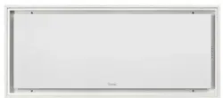
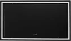
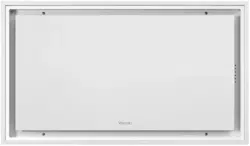
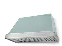
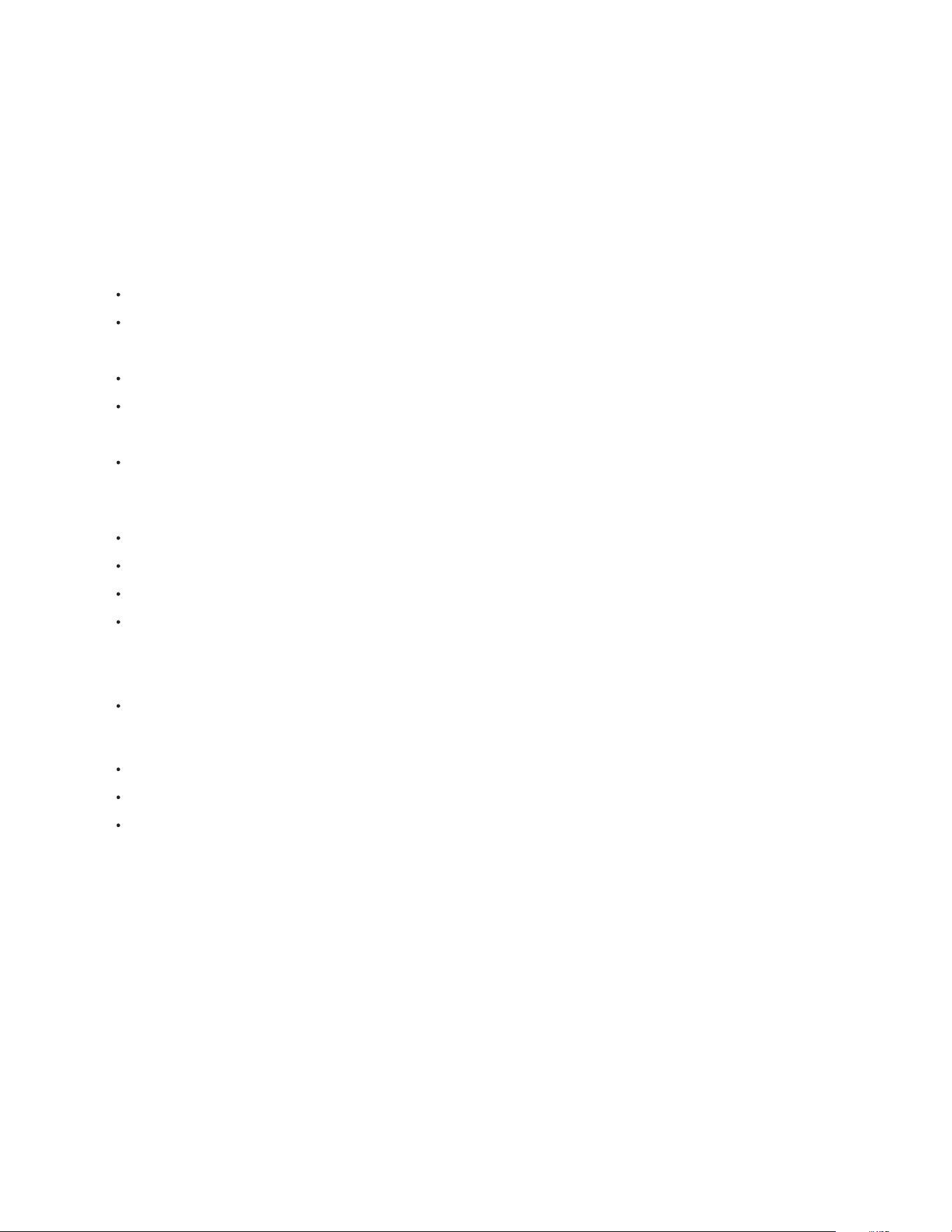
D I M E N S I O N S
5
TOP VIEW
FRONT VIEW SIDE VIEW
3D VIEW
T U S C A N Y
6
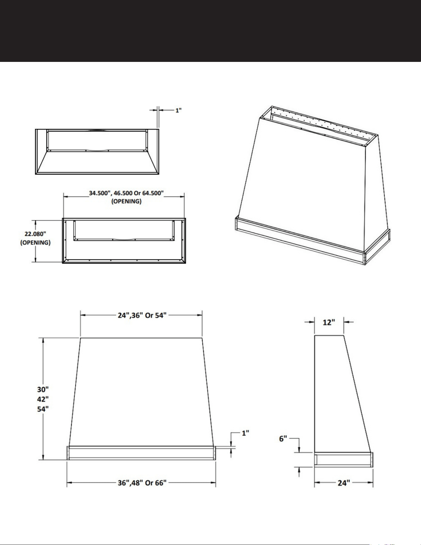
T O P / R E A R V E N T I N G O P T I O N S
Hood comes with liner installed. Carefully remove screws while holding the liner in place so it doesn’t fall forward
and damage your hood. Take liner out for installation of shell by removing the baffle filters and locate the bolts
on the L/R sides holding it in. Once liner is removed, place hood in the location you want it installed in, locate the
studs using a stud finder and secure the hood to the wall with appropriate bolts/lags (mounting hardware not
supplied due to various surface needing different requirements). Holes are provided in staggered design across
the bottom and top mounting bars for flexible mounting options regardless of where your studs are behind the
wall.
Ducting – Rear or Top Vent Options Ducting is brought into the hood from above or through the rear wall with a
90 degree transition (not provided). Measure proper length prior to installing liner and seal properly with duct
tape. Ensure you use 8” duct for 600 cfm models, and 10” duct for 1200 cfm models for the entire duct run, with
equivalent sized roof or wall caps to ensure best performance.
IMPORTANT: No portion of any length of duct pipe or fitting should be smaller than the duct collar of
the hood/liner. This is very important because any type of restriction anywhere in the ventilation system
will cause increased static pressure (air resistance), that may result in rattling, vibration and air buffeting
noises, as well as inadequate ventilation.
7
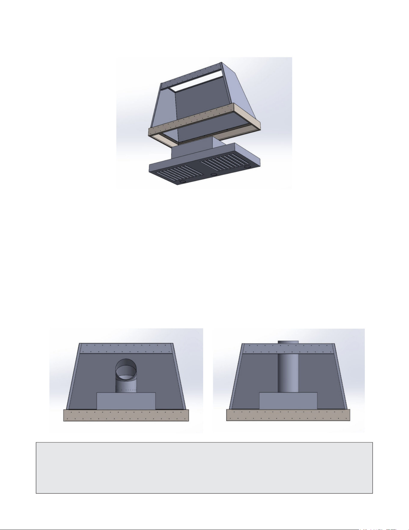
E L E C T R I C A L C O N N E C T I O N
For 36 & 48” hoods, electrical connection is located in the junction box on the Right side of the liner,
with EKO located 4” up from bottom of hood and 7” from front, and 2 ½” from right of hood (facing
wall perspective).
Feed the Power Supply Cable through the electrical knockout. Connect the Power Supply Cable to the
range hood cable. Attach the Power Supply Cable grounding lead to the Green wire provided. Attach
the White lead of the power supply to the White lead of the liner with a twist-on type wire connector.
Attach the Black lead of the power supply to the Black lead of the liner with a twist-on type wire
connector.
Replace the cover.
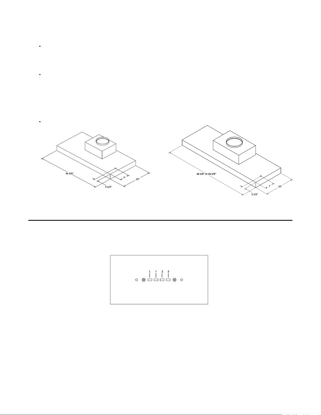
Light (L) - Switches the lights on and off.
Motor - Motor Speed Selection 1- Low, 2- Medium, 3- High on/off
Speed - Sets the operating speed of the liner:
1 - Low speed, suitable for most operating conditions giving the optimum treated air flow/noise level ratio.
2 - Medium speed, used for a continuous and almost silent air change in the presence of light cooking vapor.
3 - Maximum speed, used for eliminating the highest cooking vapor emission.
O P E R A T I O N A L U S E
36” 600 CFM Models
EKO Location
Control Board
48” & 66" 1200 CFM Models
EKO Location

8
C A R E
CLEANING S TAINLESS S TEEL BAFFLE FILT ERS
•
•
•
•
LED Bulb, 120V, GU10/MR16, 5 Watts, 500 Lumens, 3000K (natural warm white color temperature)
The filters should be cleaned regularly (and more frequently for heavy usage) and can be washed in a
dishwasher.
Remove the filters one at a time by supporting them with one hand on each handle, slide toward front
of liner, drop rear side of filter, and slide slightly back to remove.
Wash the filters in your dishwasher ensuring the detergent inlet holes are facing upwards in your
dishwasher rack. Allow them to dry before reinstalling baffle filters.
Re install filters in reverse order of removal, starting with inserting filter in channel behind light bar
and slide forward, lift back of filter into place and slide filter back till fully seated in channel to back of
liner.
To remove light, place two fingers on the LED bulb, place slight pressure upwards on the bulb while twisting
¼ turn counterclockwise and release being careful to catch bulb as it comes out of socket.
If possible, replace with another of the same style/wattage by aligning the two pins in the LED housing,
apply slight pressure with two fingers upward on the bulb while twisting it ¼ turn clockwise to secure in
place.
Replacement bulbs can be purchased at most home or grocery stores. Exact replacement bulbs can be
purchased at www.vikingrange.com
•
•
•

BEST PRACTICES FOR INSTALLATION
Kitchen hood/liners should be installed by qualified technicians familiar with state and local building codes.
Use round or rectangular rigid metal duct only. Where possible, use round duct as it creates the least
amount of static pressure. It is recommended that you do not use flex duct.
All duct sections and fittings, should overlap and be connected with at least 3 – 4 equally spaced
screws and wrapped tightly with 2 – 3 layers of Aluminum Foil Metal Duct Tape. This type of duct
tape is more durable than traditional cloth duct tape. Do not use butt joints.
For best air flow, elbows and pipe size transition fittings should not be directly connected to one
another. Where possible, always include at least 15 inches of straight pipe between fittings.
IMPORTANT Problems caused by the improper installations are not covered by the manufacturer’s warranty.
IMPORTANT Undersized and improperly installed duct pipe and/or other ventilation components will cause
excessive static pressure (air resistance), that may result in rattling, vibration and air buffeting noises, as well
as inadequate ventilation.
(See Duct Sizing Chart and Area Calculations section on page 3 for more details)
IMPORTANT The required duct size is indicated by the size of the duct collar on the hood or liner.
IMPORTANT No portion of any length of duct pipe or fitting should be smaller than the duct collar of the
hood/liner. This is very important because any type of restriction anywhere in the ventilation system will cause
increased static pressure (air resistance), that may result in rattling, vibration and air buffeting noises, as well
as inadequate ventilation.
DUCT RUNS - LENGTH
Configure the ventilation duct run to be as short and as direct to the outside as possible. Minimize the
number of elbows and transition fittings used. Complex or long runs should be reviewed by a qualified
installer.
No portion of the ducting should be run so that the exhaust air flows downward. Since exhaust heat rises,
forcing the air to flow downward will cause increased static pressure. As previously mentioned,
improperly installed duct pipe will cause excessive static pressure (air resistance), that may result in
rattling, vibration and air buffeting noises, as well as inadequate ventilation.
Duct runs for 390 CFM hood/liner models should not exceed 20 linear feet with two 90-degree elbows (or
four 45- degree elbows), a damper and a roof or wall cap. Longer runs or additional elbows will result in
decreased ventilation performance. Each 90-degree elbow is the equivalent of 8 linear feet of duct pipe;
each 45-degree elbow is equivalent to 4 linear feet of duct pipe.
IMPORTANT The required duct size is indicated by the size of the duct collar on the hood or liner.
IMPORTANT No portion of any length of duct pipe or fitting should be smaller than the duct collar of the
hood/liner. This is very important because any type of restriction anywhere in the ventilation system will cause
increased static pressure (air resistance), that may result in rattling, vibration and air buffeting noises, as well
as inadequate ventilation.
1 . B U I L D I N G C O D E S
3. DUCT PIPE & FITTING SIZES
2. DUCT PIPE & FITTINGS (ELBOWS, TRANSITIONS, ROOF & WALL CAPS)
© 2 0 2 5 T R A D E - W I N D M A N U F A C T U R I N G , L L C
9

4. DAMPERS
The roof cap or wall cap is the termination point of the venting system that allows the exhaust air to exit to the
outdoors. All sections of this fitting must have an equal or greater air path area than the hood/liner’s duct collar.
If any section of the roof cap or wall cap is smaller than the hood/liner’s duct collar, the entire ventilation system
will lose performance and the restriction will cause increased static pressure.
IMPORTANT: Even though the intake side of the roof cap or wall cap may be properly sized, roof caps or wall
caps with built-in dampers must be made so that when the damper is fully open, the actual open area of the
exit point is equal to or greater than the duct collar of the hood/liner. Any undersized portion of a roof cap or
wall cap will cause excessive static pressure that may result in rattling, vibration and air buffeting noises, as
well as inadequate ventilation.
• 390 CFM Models
390 CFM models have either a 3.25” x 10” rectangular metal damper attached directly to the hood/liner or a
7” duct collar that requires a 7” damper (sold separately).
• 600 – 1200 CFM Models
600-1200 CFM models have either an 8” or 10” round duct collar that requires use of a damper with the
corresponding dimension (sold separately).
Damper In Roof Cap Or Wall Cap: In ventilation systems utilizing a roof cap or wall cap with a built-in
damper, do not install an additional in-line damper. Two dampers are unnecessary and will cause increased
static pressure (air resistance), that may result in rattling, vibration and air buffeting noises, as well as
inadequate ventilation.
In-line Damper: In cold weather areas, installing an “in-line” damper may be the preferred type of installation.
This is because in-line dampers installed just above the perimeter of the heated space (the ceiling) will reduce
the amount of cold air traveling down the duct into the heated space and into the kitchen through the hood/
liner. In-line dampers must be installed so that the exhaust air-flow will open the butterfly blades.
Horizontal Duct Runs: The in-line damper must be installed so that the hinge between the two butterfly blades
is vertical—the hinge pin must point up and down. Otherwise, because of gravity, the damper’s blades will not
close and the damper will not prevent backdrafts.
Vertical Duct Runs: The in-line damper’s hinge will be horizontal (sideways), which is correct for vertical duct
runs. Gravity will help close the damper blades after each use.
Upward Slanted Duct Runs: The in-line damper’s hinge must point to the top and bottom sides of the duct.
In this position, gravity will help close the damper blades after each use. Otherwise, because of gravity, the
damper’s blades will not close and the damper will not prevent backdrafts.
IMPORTANT: do not use screws to attach any type of damper as the screws may block the damper blades.
IMPORTANT: do not use more than one damper in the ventilation system.
NOTE: Many styles of roof caps and wall caps have built-in dampers. See Roof Caps and Wall Caps section for
more detail. Always use carefully crafted, tightly wrapped Aluminum Foil Metal Duct Tape on all connections
and physically view and test the damper blades to make certain they are opening and closing correctly.
Make sure that the damper blades do not touch the duct walls and that there is no debris blocking the free
movement of the damper mechanism. Common things to look for include screws protruding into the blade’s
path, over spray of paint, plaster and insulation. If using rectangular duct, be sure that all four sides of the duct
are on the outside of the damper’s duct collar or frame. On hood/liner installations designed to recirculate the
exhaust air back into the kitchen, be sure to remove the aluminum damper blade before attaching the duct
to the damper frame.
10
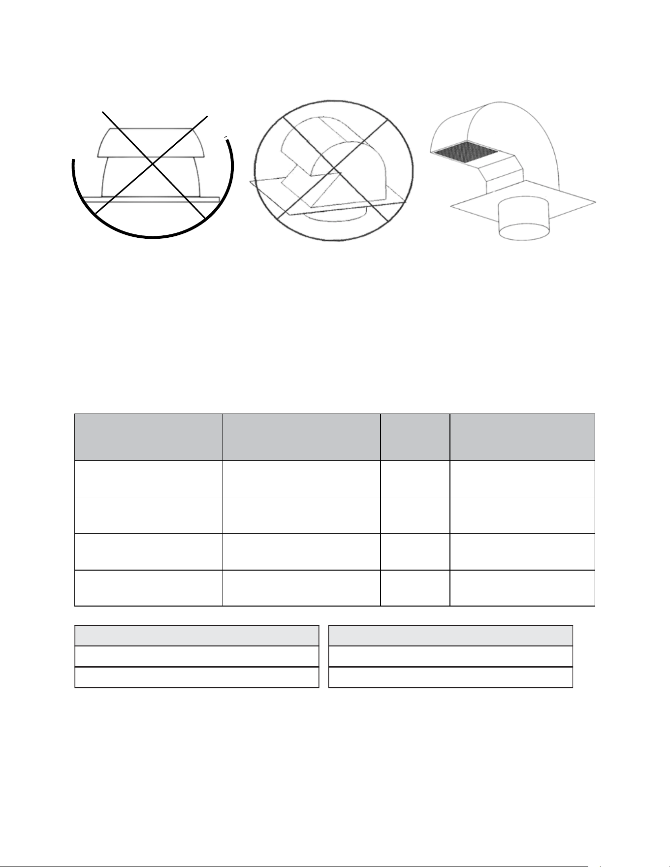
5. ROOF CAPS & WALL CAPS
DUCT COLLAR TYPES & SIZES
DUCT TYPE REQUIRED
DUCT SIZE
(SQ. IN.)
MINIMUM ROOFCAP OR
WALLCAP OPENING SIZE
6” diameter, round
6” round metal duct
28. 3”
28. 3”
8” diameter, round
7” round metal duct
50. 25”
50. 25”
10"diameter, round
10” round metal duct
78. 5”
78. 5”
3. 25” x 10” rectangular
3. 25” x 10” rectangular metal duct
32. 5”
32. 5”
The “radius” is one-half the diameter of a round duct,
e. g. , ½ of a 10” round duct is 5”. 3. 1416 is “Pi”, the
“constant” used when calculating the area of a circle.
ROUND DUCT
RADIUS x RADIUS x PI = AREA (SQ. IN.) ________ x
________ x ________ = ______________
RECTANGULAR DUCT OR WALL/ROOF CAP
WIDTH x DEPTH = AREA (SQ. IN.)
_______ x ________ = ______________
ROOF CAPS AND WALL CAPS MUST HAVE AN INTEGRAL BIRD SCREEN.
The ventilation system should be attached to the framework in such a manner that the weight of the duct and
fittings is supported with no stress on the duct joints, fittings or on the hood/liner. All ducting should be
attached so as to avoid any possible duct vibration from being transferred to the house’s framework.
6. ATTACHING DUCT TO HOUSE FRAMEWORK
7. DUCT SIZING CHART & AREA CALCULATION
No Mushroom Cap Style No “Goose-Neck” Style
Only use a shape that looks like the
picture shown. Call VIKING®
Customer Service for any questions.
11

Service & Registration
If service is required, call your dealer or authorized service agency.
The name of the authorized service agency can be obtained from the dealer or distributor in your area.
Have the following information readily available.
• Model number
• Serial number
• Date purchased
• Name of dealer from whom purchased
Clearly describe the problem that you are having. If you are unable to obtain the name of an authorized
service agency, or if you continue to have service problems, contact Viking Range, LLC at1-888-(845-4641),
or write to:
VIKING RANGE, LLC
PREFERRED SERVICE
111 Front Street
Greenwood, Mississippi 38930 USA
Record the information indicated below. You will need it if service is ever required. The model and serial
number for your hood is located behind the baffle filter on the left side panel in the lower right corner.
M o del n o . ______________________________________________ S e r i a l n o . __________________________________________________________
D a te of p u r chas e ______________________________________ D a te in s t a l l e d ____________________________________________________
D e aler ’s name __________________________________________________________________________________________________________________
Address __________________________________________________________________________________________________________________________
____________________________________________________________________________________________________________________________________
If service requires installation of parts, use only authorized parts to ensure protection under the warranty.
THIS MANUAL SHOULD REMAIN WITH THE HOOD FOR FUTURE REFERENCE.

Viking Range, LLC
111 Front Street
Greenwood, Mississippi 38930 USA
(662) 455-1200
For product information, call 1-888-(845-4641)
or visit our web site at vikingrange.com
Published 02/2025