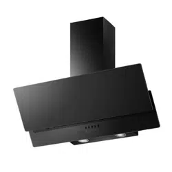
USER MANUAL
60CM SLOPING COOKER HOOD
eiQSRG60
Thank you for choosing your electriQ cooker hood.
This instruction manual is designed to provide you with all required instructions
related to the installation, use and maintenance of the appliance. In order to operate
the unit correctly and safely, please read this instruction manual carefully before
installation and usage.

2
CONTENTS
SAFETY
3
INSTALLATION
5
OPERATION
10
FILTER INFORMATION
10
BULB REPLACEMENT
12
CLEANING AND MAINTENANCE
13
TROUBSLEHSOOTING
14
SUPPORT
14
PRODUCT FICHE
15

3
SAFETY PRECAUTIONS
Whilst this product is compliant with all safety requirements, incorrect or
inappropriate use can lead to both personal injury and potential damage
to property. Please read the contents of this instruction booklet thoroughly
before fitting or using this appliance.
• The cooker hood must be installed in accordance with the installation
instructions and all measurements followed.
• All installation work must be carried out by a competent person or
qualified electrician.
• The unit must be connected to an earthed power supply.
• If venting externally, make sure the ducting has no bends sharper than
90 degrees as this will reduce the efficiency of the cooker hood.
• The cooker hood is for domestic use only and is not designed for
commercial use. It should only be used for the purpose it was intended –
to extract vapours and cooking odours.
• Do not flambé or use an open flame under the cooker hood.
• Do not try to use the cooker hood without the grease filters or if the filters
are excessively greasy! They should be cleaned regularly (see
“Maintenance”) or replaced as necessary.
• The extraction fan must be level to avoid grease collection at one end, as
this could cause a potential fire risk.
• Do not leave frying pans unattended during use because overheated fat
or oils might catch fire.
• If the cooker hood is damaged, do not attempt to use it.
• If the supply cord is damaged, it must be replaced by the manufacturer,
its service agent or a similarly qualified person in order to avoid a hazard.
• This appliance can be used by children aged from 8 years and above and
persons with reduced physical, sensory or mental capabilities or lack of
experience and knowledge if they have been given supervision or
instruction concerning use of the appliance in a safe way and understand
the hazards involved.
• Children shall not play with the appliance. Cleaning and user
maintenance shall not be made by children without supervision.
• Children should be supervised to ensure that they do not play with the
appliance. It is not a toy.
• The plug must be accessible after installation for isolation in case of an
emergency – or an appropriate fused switch if the unit is hard-wired to
the mains via a spur.
• The minimum distance between the surface of the hob and the lowest
part of the hood should be at least 65cm. A distance of between 65cm
and 75cm gives peak efficiency.

4
• The air must not be discharged into a flue that is used for exhausting
fumes from appliances burning gas or other fuels.
• When the hood is vented externally and used with appliances which burn
fuel (e.g. gas, oil, wood) the area must be sufficiently ventilated to ensure
safe operation. Fresh air must be allowed to freely enter the room to
prevent a partial vacuum.
• A partial vacuum can starve the heating appliance of oxygen, impairing
combustion. It can also prevent toxic fumes from leaving the room, or
can cause fumes to be sucked into the room from outside.
• Safe operation is only possible when the partial vacuum within the
working area does not exceed 4 Pa (0.04 mbar). This can be achieved
by ensuring air is able to enter the room from outside through a suitable
sized opening which cannot be sealed during operation. A number of
alternative solutions are available to ensure this. If in any doubt,
professional advice should be sought.
• Regulations concerning the discharge of air have to be fulfilled.
• There is a potential fire risk if cleaning is not carried out in accordance
with the instructions.
• Clean your appliance periodically by following the method given in the
chapter MAINTENANCE
• If used in recirculation mode, the charcoal filters trap odours and must be
replaced at least once a year depending on how frequently the cooker
hood has been used.
• For safety reason, please use only the same size of fixing or mounting
screw, which are recommended in this instruction manual.
• Warning: Failure to install the screws or fixing device in accordance with
these instructions may result in electrical hazards
CAUTION: Accessible parts of the hood can become very hot during
use with cooking appliances, whether in use or not, due to heat rising from
the hob. Sufficient time should be allowed for the unit to cool before
touching either the housing or the grease filters.

5
PARTS LIST
No.
Description
Drawing
QTY (pc)
1
Cooker Hood
1
2
outside chimney
1
3
inside chimney
1
4
outside chimney bracket
1
5
inside chimney bracket
1
6
wall plug
8
7
screw ST4*40mm
4
8
screw ST4*30mm
4
9
screw ST4×8mm
6
10
v-flap
1 pair
11
converter
1
6
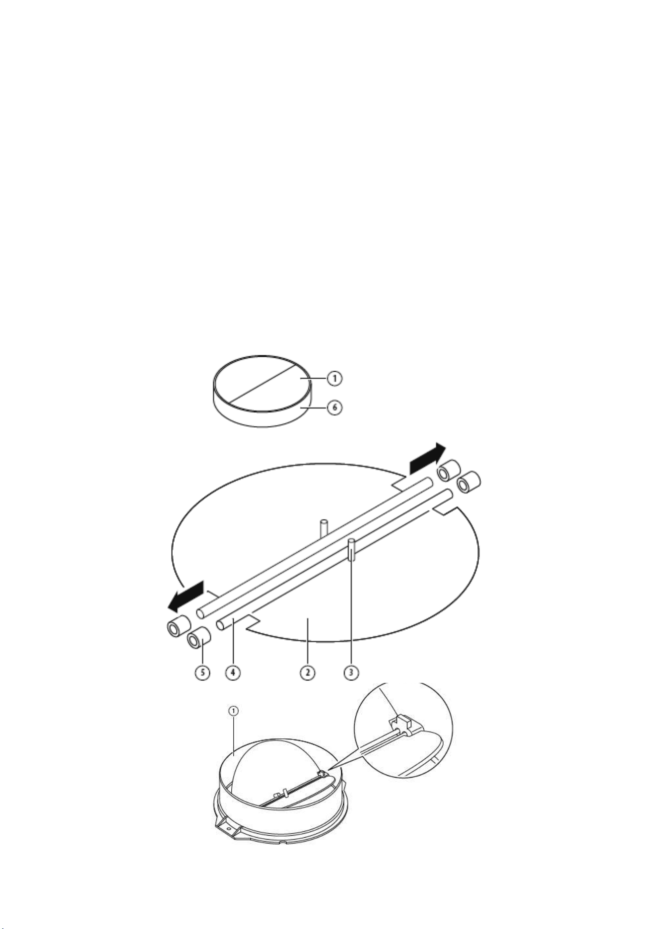
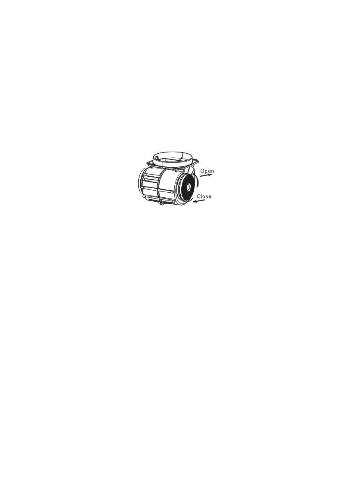
INSTALLATION (VENT OUTSIDE)
MOUNTING OF THE V-FLAP
If the cooker hood does not have an assembled V-flap 1, you should mount the half-
parts to its body. The images only show an example of how to mount the V-flap, the
outlet may be various according to different models and configuration.
To mount the V-flap 1 you should:
1. Mount two half-parts “2” into the body “6”
2. A pin 3 should be top oriented
3. The axis “4” should be inserted in the holes “5” on body
4. Repeat all the operations for the 2nd half-part
7
INSTALLATION
If you have an outlet to the outside, your cooker hood can be connected as below
picture by means of an extraction duct (enamel, aluminum, flexible pipe or non-
flammable material with an interior diameter of 150mm)
1. Before installation, turn the unit off and unplug it from the outlet.
2. The cooker hood should be placed at a distance of 65~75cm above the cooking
surface for best effect.
3. After decide the cooker hood height, measure the position of the holes for hanging
hood , inside chimney bracket ,outside chimney bracket and safety holes. Drill 8 φ8
holes and insert wall plugs into the holes. Fix the inside chimney bracket on the
wall with 2pcs ST4 x 40mm screws. Screw 2pcs ST4 x 8mm screws in the hole for
hanging the hood body and the screws installed should leave for 3-5mm out of the
wall to hang the hood. The fixed position of the inside chimney bracket is the
highest place of chimney. See pic 2.
4. Install the converter, v-flap and expansion
pipe onto the cooker hood. Fix the expansion
pipe on the outlet with a cable tie. See Pic 3.
Note: The expansion pipe is not included in
the product. Hang the cooker hood onto the
hook. See pic 4.
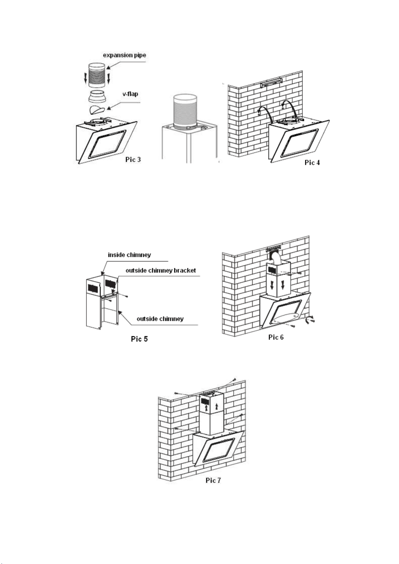
8
5. Install the outside chimney bracket onto the outside chimney with 2 ST4*8mm
screws, here should be sure the inside chimney can be flexed freely. See Pic 5.
6. Fix the cooker hood with 2pcs ST4*30mm safety screws. Note: The two safety
vents are positioned on the back housing, with a diameter of 6mm.Put the two
chimneys onto the cooker hood, fix the outside chimney on the wall with 2pcs
ST4*40mm screws and lead the expansion pipe to the outside. See pic 6.
7. Adjust the height of the inside chimney to the position of the inside chimney bracket
and fix on it with 2pcs ST4*8mm screws. Fix the outside chimney onto the hood
body with 2pcs ST4*8mm screws. See Pic 7.
9
HINTS FOR EXHAUST DUCT INSTALLATION
The following rules must be strictly followed to obtain optimal air extraction:
• Keep exhaust duct short and straight
• Do not reduce the size or restrict the exhaust duct
• When using the flexible duct always install the duct pulled taut to minimize pressure loss
• Failure to observe these basic instructions will reduce the performance and increase noise
levels of the range hood.
• Any installation work must be carried out by a qualified electrician or competent person.
• Do not connect the ducting system of the hood to any existing ventilation system which is
being used for any other appliance, such as warmer tube, gas tube, hot wind tube.
• The angle of the bend of the ventilation pipe should not be less than 120º; you must direct
the pipe horizontally, or, alternatively, the pipe should go up from the initial point and should
be led to an outer wall.
• After the installation, make sure that the cooker hood is level to avoid grease collection at on
end.
Ensure the exhaust ducting selected for installation complies with relevant standards
and is fire retardant.
10
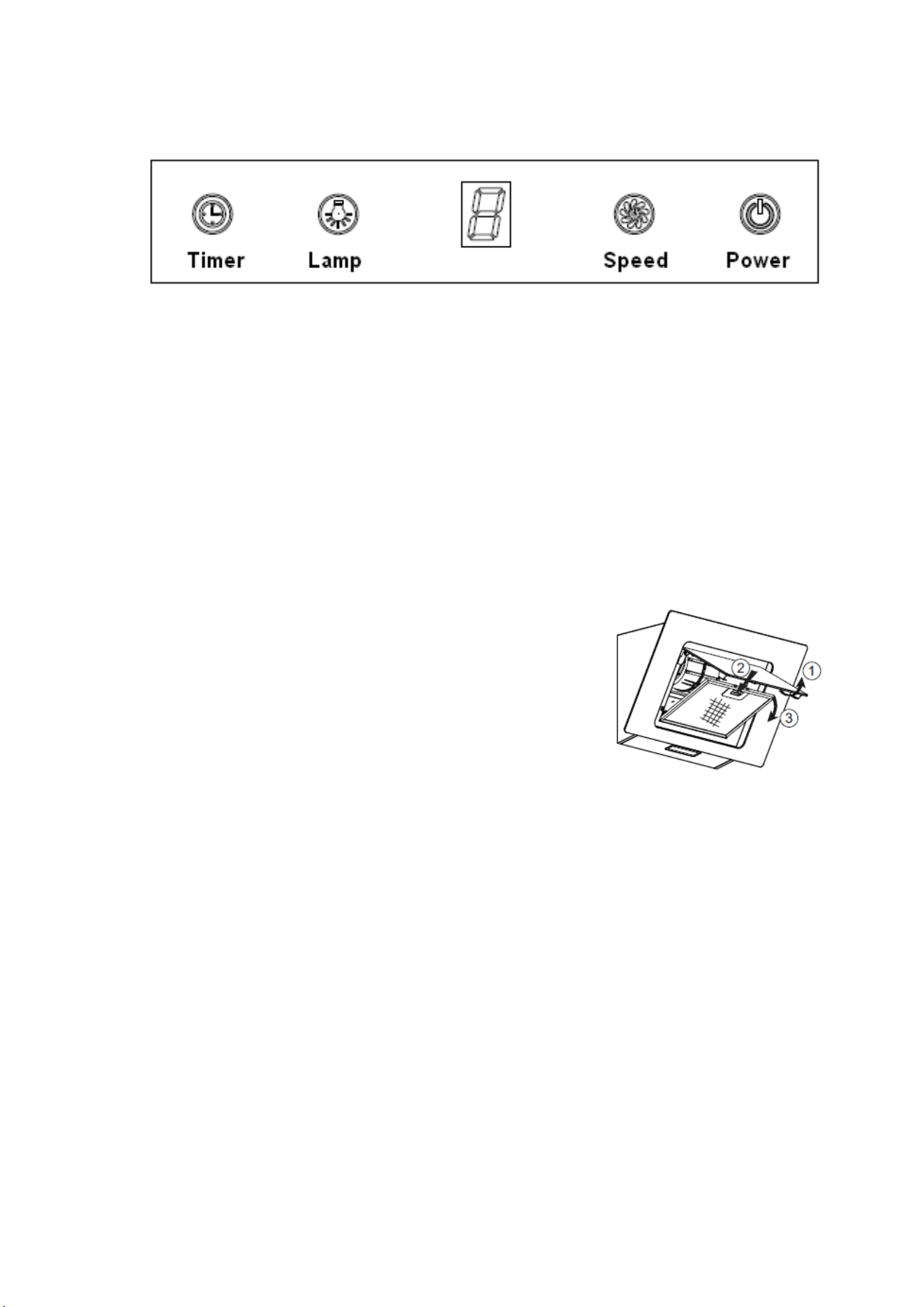
OPERATION
1. Press the “Power” button, to turn the cooker hood on and off.
2. Press the “Speed” button to cycle between fan speeds, the LED display will
indicate the fan speed with the numbers 1, 2 and 3.
3. Press “Lamp” button to turn the hoods light on and off.
4. Press the “Timer” button, and the cooker hood will start a countdown of 9
minutes (this will be shown on the display (9-8-7-6 etc.) When the timer has
finished, the cooker hood and all functions will be turned off. To cancel the
timer, press the timer button again.
GREASE MESH FILTERS
The mesh filters can be cleaned by hand. Soak them for
about 3 minutes in water with a mild detergent and then
brush it gently with a soft brush. Please do not apply too
much pressure so as to avoid any damage to it. (Leave to
dry naturally out of direct sun light)
Filters should be washed separately to crockery and
kitchen utensils. It is advisable not to use rinse aid. Following the picture beside to
dismantle the grease filter.
INSTALLING GREASE MESH FILTERS
• To install filters for the following four steps:
- Angle the filter into slots at the back of the hood.
- Push the button on handle of the filter.
- Release the handle once the filter fits into a resting position.
- Repeat to install all filters.
Replacement filters can be purchased from the supplier of your
cooker hood using the following code:
Grease filter - eiqgfrg x 1
11
CARBON FILTER
(Not Supplied)
Activated carbon filter can be used to trap odors. Normally the activated carbon filter
should be changed every 3 to 6 months according to your cooking habits. The
installation procedure of activated carbon filter is as below:
1. Before installing or replacing the carbon filters, please disconnect mains power
to the unit.
2. Press the filter lock and remove the mesh filter.
3. Turn the carbon filter on both sides of the motor anti-clockwise. Replace the
carbon filters with the new carbon filters.
4. Place the mesh filter.
5. Connect the power supply to the wall socket.
NOTE:
• Make sure the filter is securely locked. Otherwise, it would loosen and cause
danger.
• When activated carbon filter attached, the suction power will be lowered.
Replacement filters can be purchased from the supplier of your
cooker hood using the following code:
Carbon filter - eiqcf130
12
BULB REPLACEMENT
The bulb must be replaced by the manufacturer, its service agent or similarly qualified
persons.
Always switch off the electricity supply before carrying out any operations on the
appliance. When handling bulb, make sure it is completely cool down before any direct
contact to hands.
When handling globes hold with a cloth or gloves to ensure perspiration does not come
in contact with the globe as this can reduce the life of the globe.
Before changing the lights, make sure that the appliance is plugged off.
• Protect against danger when changing lights, such as wearing gloves.
CHANGING THE LIGHTS
1. Remove the grease filter.
2. Put one hand into the cavity to gently push out the LED light, and use the other hand
to grab the light and pull it out, and then pull out the light cable.
3. After changing the lamp, plug in the lamp cable, and put the lamp into the lamp hole.
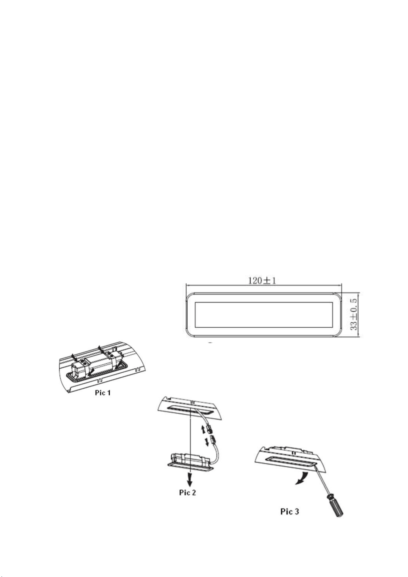
ILCOS D code for this lamp is: DSS-1.5/65-S-120/33
• LED modules– rectangle LED lamp
• Max wattage: 1×1.5W
• Voltage range: DC 12V
• Dimensions:

13
MAINTENANCE
Before cleaning, switch the unit off and pull out the plug, or switch off at the relevant
mains switch if the unit has been hard-wired in. Make sure the unit has no power being
fed to it.
REGULAR CLEANING
Use a soft cloth moistened with warm mildly soapy water or household cleaning
detergent. Never use metal pads, chemicals, abrasive material or a stiff brush to clean
the unit.
STAINLESS STEEL
The stainless steel must be cleaned regularly (e.g.weekly) to ensure long life
expectancy. Dry with a clean soft cloth. A specialized stainless-steel cleaning fluid may
be used.
NOTE: Ensure that wiping is done along with the grain of the stainless steel to prevent
any unsightly crisscross scratching patterns from appearing.
CONTROL PANEL SURFACE
The inlay control panel can be cleaned using warm soapy water. Ensure the cloth is
clean and well wrung before cleaning. Use a dry soft cloth to remove any excess
moisture left after cleaning.
IMPORTANT
Using neutral detergents and avoid using harsh cleaning chemicals, strong household
detergents or products containing abrasives,as this will affect the appliance
appearance and potentially remove any printing of artwork on the control panel and
will void manufactures warrantee.
14
TROUBLESHOOTING
FAULT
CAUSE
SOLUTION
Light on, but fan
does not work
The fan blade is
jammed.
Switch off the unit. Repair to be carried
out by qualified service personnel only.
The motor is
damaged.
Both light and
fan do not work
Light bulb blown
Replace the bulb with correct rating.
Power cord loose
Plug in to the power supply again.
Excessive
Vibration
The fan blade is
damaged.
Switch off the unit. Repair to be carried
out by qualified service personnel only.
The fan motor is not
fixed tightly.
Switch off the unit. Repair to be carried
out by qualified service personnel only.
Suction
performance
not good
1 Grease filters
clogged
2 Distance between
the unit and the
cooking plane too
great.
1 Clean or replace grease filters.
2. Readjust the distance to between
65cm and 75cm.
INFORMATION FOR DISMANTLING
Do not dismantle the appliance in a way which is not shown in the user manual. The appliance
could not be dismantled by user. At the end of life, the appliance should not be disposed of with
household waste. Check with you Local Authority or retainer for recycling advice.
electriQ UK SUPPORT
www.electriQ.co.uk/support
www.electriQ.co.uk
Call: 0330 390 3061
Office hours: 9AM - 5PM Monday to Friday
Unit J6, Lowfields Business Park
Lowfields Way, Elland
West Yorkshire, HX5 9DA
Recycling facilities are now available for all customers at which you
can deposit your old electrical products. Customers will be able to
take any old electrical equipment to participating sites run by their
local councils. Please remember that this equipment will be further
handled during the recycling process, so please be considerate
when depositing your equipment. Please contact the local council for
details of your local household waste recycling centres.
15
PRODUCT FICHE
Symbol
Value
Unit
Model identification
eiQSRG60
Annual Energy
Consumption
AEC
hood
26.3
kWh/a
Time increase factor
f
1.5
Fluid Dynamic Efficiency
FDE
hood
14.5
Fluid Dynamic Efficiency
class
Class D
Energy Efficiency Index
EEI
hood
63.5
Energy Efficiency class
Class B
Maximum airflow
Q
max
278.5
m
3
/h
Measured airflow rate at
the best efficiency
Q
BEP
165.9
m
3
/h
Measured air pressure at
best efficiency point
P
BEP
145
Pa
Measured electric power
input at best efficiency
point
W
BEP
46
W
Nominal power of the
lighting system
W
L
1.5
W
Average illumination of
the lighting system on the
cooking surface
E
middle
73
lux
Measured power
consumption on off mode
P
O
0.42
W
Measured power
consumption on standby
mode
P
S
-
W
Sound power level
L
WA
Highest setting:65
Lowest setting:60
dB