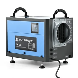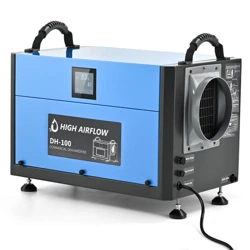
COMMERCIAL DEHUMIDIFIER
Model:ZX-DH-80/ZX-DH-100
Instruction Manual

Dear Customer:
Welcome to our family. Thank you for purchasing one of our products.
Our goal is to provide you with superior service. If there is anything missing from or
wrong with your order, or if you have any questions about using our Dehumidifier,
PLEASE contact us.
Email: [email protected]
Our team is available 24/7 to address your questions, comments, and concerns. Your
satisfaction is our ultimate goal. We want to make everything right so you'll share your
positive experience with other shoppers on Amazon.
If you experience any problems, please send an email to [email protected].
Our mission:
*To be the most trusted appliance brand.
* To create practical, compact appliances that better your life.

Contents
01
INSTRUCTIONS
SAFETY & WARNING
PARTS DIAGRAM
OPERATIONAL PRECAUTIONS
OPERATION INSTRUCTION
INSTALLATION AND ASSEMBLY OF ACCESSORIES
DRAINAGE METHOD
CLEANING AND MAINTENANCE
SAFETY PRECAUTIONS ON SERVICING
TRANSPORTATION AND CUSTODY
PRODUCT PAREMETERS
PACKING LIST
TROUBLESHOOTING
WARRANTY AND SERVICE
02
02-03
04
05
06-07
08-12
13-15
16-17
18
19
20
21
22
23

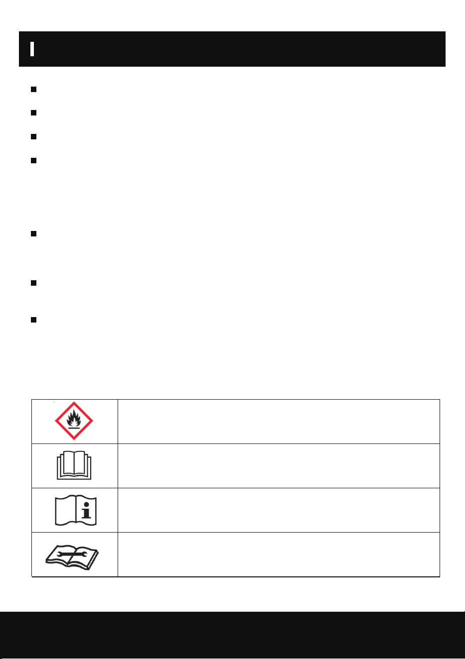
INSTRUCTIONS
SAFETY & WARNING
02
When using electrical appliances, basic safety precautions should always be followed including
the following:
Read all instructions before using this product.
This appliance can be used by children aged from 8 years and above and persons with reduced
physical, sensory or mental capabilities or lack of
experience and knowledge if they have been given supervision or instruction concerning use of
the appliance in a safe way and understand the hazards involved. Children shall not play with
the appliance. Cleaning and user
maintenance shall not be made by children without supervision.
This appliance is designed to use indoor ,not for outdoor.
The unit is designed only for use with R32(propane) gas as the designated refrigerant.
The refrigerant loop is sealed.Only a qualified technician should attempt to service!
Do not discharge the refrigerant into the atmosphere.
R32(propane)is flammable and heavier than air.
It collects first in low areas but can be circulated by the fans.
If propane gas is present or even suspected, do not allow untrained personnel to attempt to find
the cause.
The propane gas used in the unit has no odor.
The lack of smell does not indicate a lack of escaped gas.
If a leak is detected,immediately evacuate all persons from the store, ventilate the room and
contact the local fire department to advise them that a propane leak has occurred.
Do not let any persons back into the room until the qualified service technician has arrived and
that technician advises that it is safe to return to the room.
No open flames,cigarettes or other possible sources of ignition should be used inside or in the
vicinity of the units.
SAFETY & WARNING
03
Component parts are designed for propane and non-incentive and non-sparking. Component
parts shall only be replaced with identical repair parts.
FAILURE TO ABIDE BY THIS WARNINGCOULD RESULT IN AN EXPLOSION,DEATH, INJURY
AND PROPERTY DAMAGE.
If the power cord is damaged,do not attempt to repair.It must be replaced with a new power cord
supplied by the unit manufacturer in order to avoid a hazard.
WARNING
Do not use means to a ccelerate the defrosting process or to clean, other than
those recommended by the manufacturer. The appliance shall be stored in a room without
continuously operating ignition sources (for example:open flames, an
operating gas appliance or an operating electric heater. Do not pierce or burn. Be aware that
refrigerants may not contain an odour.
WARNING – Risk Of Fire. Flammable Refrigerant Used. To Be Repaired Only By Trained Service
Personnel. Do Not Puncture Refrigerant Tubing. / MISE EN GARDE – Risque d’incendie.
Contient un frigorigène inflammable. Confier la
réparation à une personne qualifiée. Ne pas perforer la tubulure contenant le frigorigène.
WARNING – Risk Of Fire. Dispose Of Properly In Accordance With Federal Or Local Regula-
tions. Flammable Refrigerant Used. / MISE EN GARDE – Risque d’incendie. Mettre au rebut
conformément aux règlements fédéraux ou locaux. Contient un frigorigè ne inflammable.
WARNING – During using, service and disposal the appliance, please pay
attention to symbol similar as left side, which is located on rear of appliance (rear panel or
compressor) and with yellow or orange color. It’s risk of fire warning symbol. There are flamma-
ble materials in refrigerant pipes and compressor. Please be far away fire source during using,
service and disposal.
This unit uses a flammable refrigerant.
If refrigerant leaks and comes in contact with a fire or heating part, it will
create harmful gas and there is a risk of fire.
Further information is available in the USER MANUAL, SERVICE
MANUAL, and the like.
Service personnel are required to carefully read the USER MANUAL and
SERVICE MANUAL before operation.
Read the USER MANUAL carefully before operation.
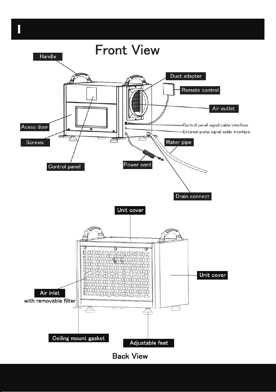
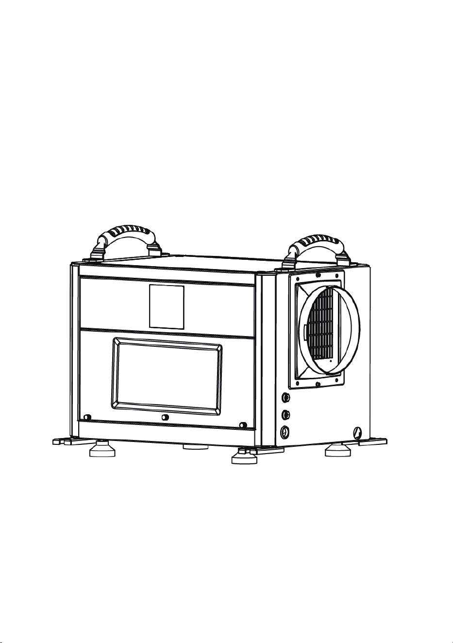
PARTS DIAGRAM
04

OPERATIONAL PRECAUTIONS
05
WARNING-to reduce the risk of fire,electric shock or injury to persons or property:
If the supply cord is damaged,it must be replaced by the manufacturer,its service agent or
similarly qualified persons in order to avoid a hazard.
The appliance shall be disconnected from its power source during service.
Always operate the unit from a power source of equal voltage,frequency and rating as indicated
on the product identification plate.
Always use a power outlet that is grounded.
Unplug the power cord when cleaning or when not in use.
Do not operate with wet hands.Prevent water from spilling onto the unit.
Do not immerse or expose the unit to rain,moisture or any other liquid.
Do not leave the unit running unattended.Do not tilt or turn over the unit.
Do not unplug while the unit is operating.
Do not unplug by pulling on the power cord.
Do not use an extension cord or an adapter plug.
Do not put objects on the unit.
Do not climb or sit on the unit.
Do not insert fingers or other objects into the air outlet.
Do not touch the air inlet or the aluminum fins of the wait.
Do not operate the unit if it is dropped, damaged or showing signs of product malfunction.
Do not clean the appliance with any chemicals.
Ensure the unit is far away from fire,inflammable,or explosive objects.
The unit shall be installed in accordance with national wiring regulations.
Do not use means to accelerate the defrosting process or to clean, other than those recommend-
ed by the manufacture.
The appliance shall be stored in a room without continuously operation sources (for exam-
ple:open flames,an operating gas appliance or an operating electric
heater).
The appliance shall be stored so as to prevent mechanical damage from occurring.
Do not piece or burn,even after use.
Be aware that refrigerants may not contain an odour.
Pipe-work shall be protected from physical damage and shall not be installed in an unventilated
space ,if that space is smaller than 4 m2 .
Compliance with national gas regulations shall be observed.
Keep any required ventilation openings clear of obstruction.
The appliance shall be stored in a well-ventilated area where the room size corresponds to the
room area as specified for operation.
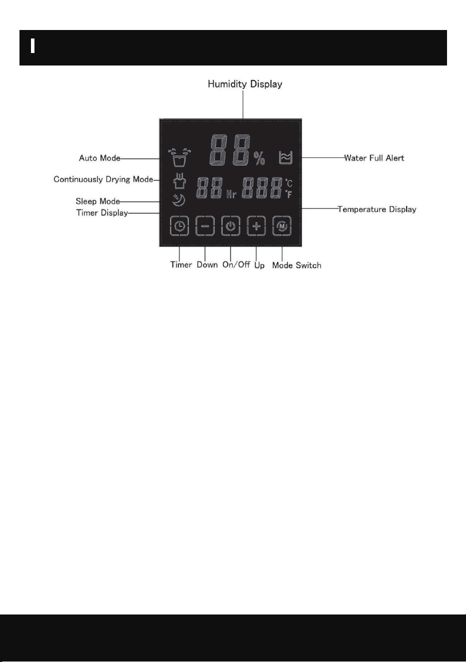
OPERATION INSTRUCTION
06
Button Description
A.On/Off(Power) Button
Press the on/off button and the machine will start running (one beep). Press the button again to
the turn the machine off. this button while on electric, screen light on,machine automatically
goes to standby mode,display screen shows environmental humidity.
B.Mode Button
Press the "mode" button, you can choose to working mode, auto mode/ continuously
drying mode / sleep mode, the corresponding mode lights on.
C.Timer
Timer/untimer can be set,while the machine is running, press the timer button light goes on, press
“+” “- ” to set the time to stop the machine, or machine is on stop status, press the timer button
and press “+” “- ” to set the time to open the machine.
D.ADD (Up) Button
Press this button to adjust the set humidity (20-90%) or timing time (0-24h) in an upward
cycle.Press the button for 3 seconds to switch between Fahrenheit and Celsius temperatures.In-
crease the humidity by pressing this button at normal mode, humidity increase 1%RH with
each press, buzzer rang each time with the press, press the button for 1 second can increase the
humidity continuously;
E.Minus (Down) Button
Press this button to down cycle to set humidity (20-90%) or timing time (0-24h).Press
the button for 3 seconds, then the temperature display will blink to display the coil temperature,
and the ambient temperature will still be displayed after 5 seconds.Decrease the humidity by
pressing this button at normal mode, humidity decrease 1%RH with each press, buzzer rang each
time with the press, press the button for 1 second can decrease the humidity continuously;

OPERATION INSTRUCTION
Operating Mode
1.Auto Mode
Default auto mode after on electric (default setting humidity 50%)
a) Environmental humidity >machine set humidity+3%, compressor, and fan start running.
Environmental humidity < machine set humidity+3%, the compressor stops, and the fan stops after
a delay of 5 seconds, and the compressor meets the three-minute delay protection.
The machine set humidity+3% ≤ environmental humidity ≤ machine set humidity+3%, and keeps
running in the original state.
b) The setting humidity is adjustable (20%-90%), and the ambient humidity (20%-95%) is displayed
after the humidity setting is completed.
2.Continuously Drying Mode
Press the mode button to select the continuously drying mode, and the light is on. a) The humidity
cannot be adjusted, and the compressor can run continuously without being restricted by the ambient
humidity (to meet the three-minute delay protection of the compressor)
b) Displays ambient humidity (20%-95%).
3.Sleep Mode (Default humidity 60%, humidity adjustable)
a) Press the mode button to select the sleep mode, and the light is on.
b) In sleep mode, if there is no button operation for 10 seconds, the display will enter a dark state.If
there is a button operation in sleep mode, it will return to normal display. After 10 seconds, if
there is no other button operation, it will continue to enter the dark display state.
c) In sleep mode, if there is a fault or the water is full, do not beep and the fault
code will be dimly displayed.
Humidity Control
In auto mode or sleep mode, press the up and down adjustment button to cyclically adjust the
set humidity. Each time the up (or down) button is pressed, the set humidity will increase (or
decrease) by 1%.
During the adjustment of the set humidity, the set humidity will flash and display, after the adjust-
ment is completed, it will flash and display 5 times to confirm, and then switch to display the ambient
humidity.
Additional Function
1. Intelligent defrosting: When a defrosting signal is detected, defrosting will start, and the corre-
sponding mode light will flash.
2. Timing function: can set timing/query timing/cancel timing
a) In the non-timing state: press the "timing" key to enter the timing setting state, the digital flashes
to display the timing time, and press the up and down keys to adjust the timing time (0~24h) during
the flashing period.
b) In the timing state: press the "timing" button, the timing time will be displayed by flashing, and
press the "timing" button again during the flashing to cancel the timing.
3. Water-full protection: When the water-full signal is detected, the water-full light is on and the
digital flashes to display "FL", the buzzer beeps 5 times to alarm , and the machine is turned off.
After power failure and drainage, resume normal operation.
08
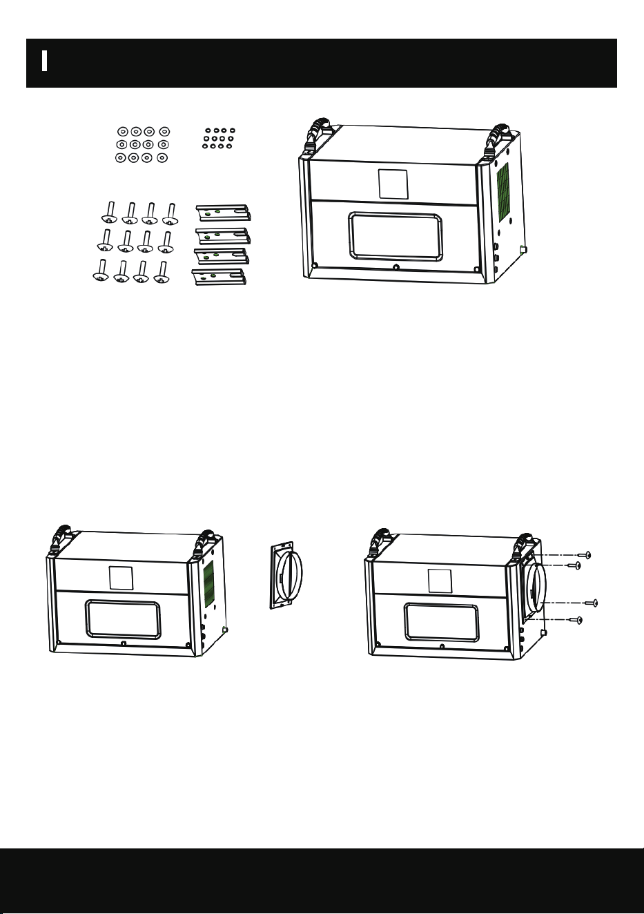
INSTALLATION AND ASSEMBLY OF ACCESSORIES
1.Take out the accessories from the packing box: ceiling mount gasket, screws, duct adapter.
2.Ducting installation
a.Align the duct adapter with the 4 screw positioning holes on the side. b. Lock and fix the duct
adapter with screws.
c.The user can put the exhaust pipe (purchased by the user according to the demand) on the duct
adapter, and it must be placed within the buckle
position.
d.You can install the flex duct yourself,the duct adapter diameter is 6.88inch/ 17.5cm.
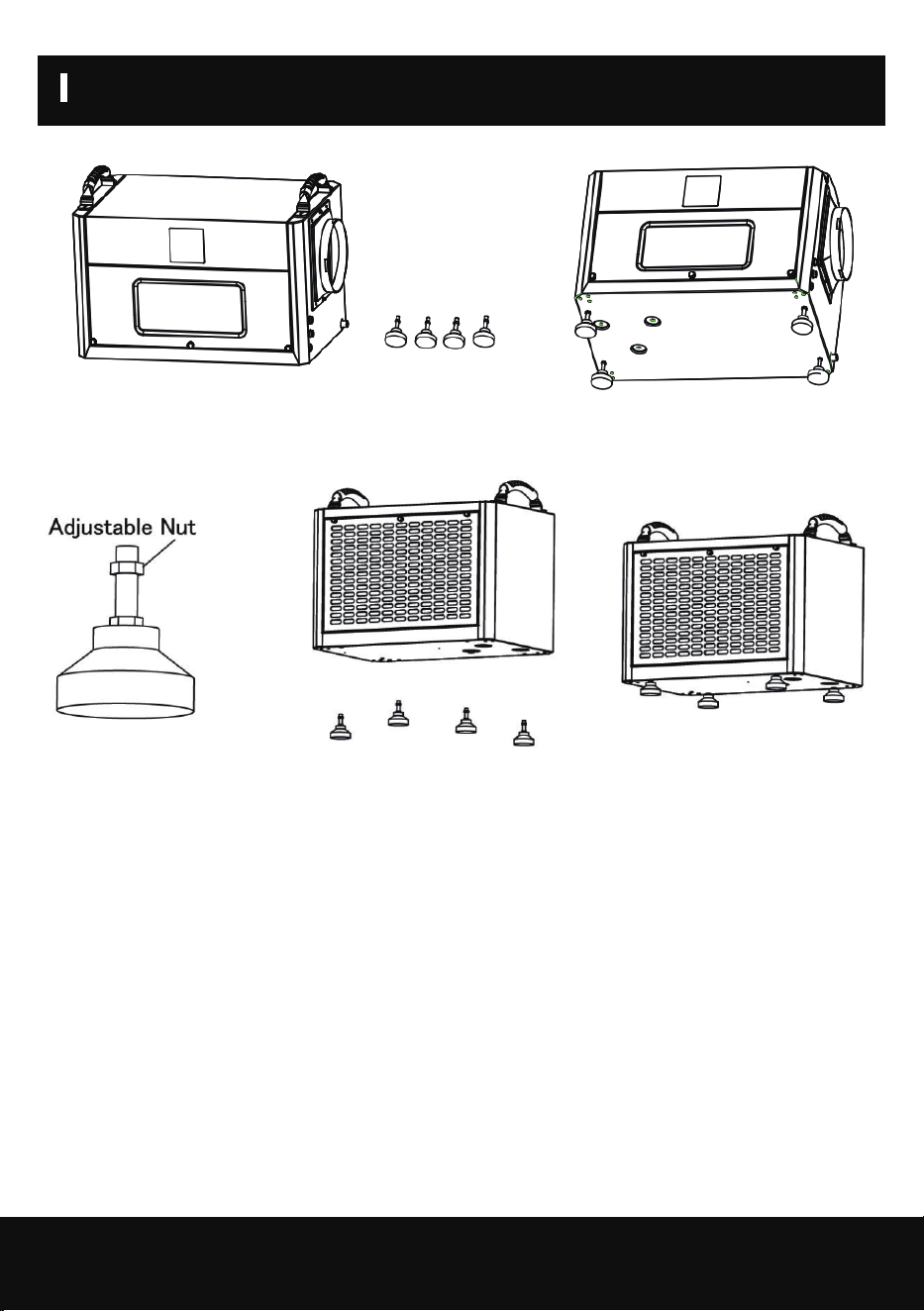
3 .Adjustable feet installation
When the machine is placed on the ground or used on some platforms, feet need
to be installed
a.It is necessary to install 4 feet on the bottom plate of the body.
b.Adjust the height of the position adjustment nuts of the 4 feet to a suitable position.
c.Assemble the 4 feet in the threaded holes on the bottom plate of the body respectively, and
lock tighten.
09
INSTALLATION AND ASSEMBLY OF ACCESSORIES
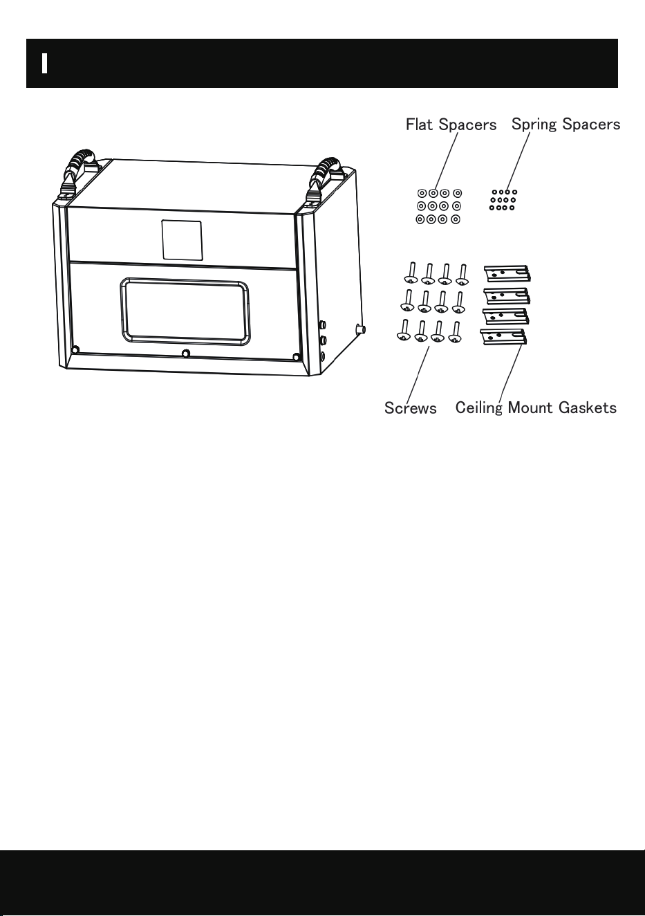
4.Ceiling mount gasket installation
When the machine is suspended in the air, the machine needs to be installed with
ceiling mount gasket.
a.Install the ceiling mount gasket in the body (accessories: 4 ceiling mount gaskets, 12 spring
spacers, 12 flat spacers, 12 screws)- 1 screw with 1 spring shim and 1 flat shim.
b.Screw the shimmed screw through the boom hole and screw it into the threaded hole on
the base plate of the machine and lock tighten.
c.Each ceiling mount gasket is installed with 3 screws, and the 4 ceiling mount gasket are
assembled on the bottom plate of the machine and locked tighten.
10
INSTALLATION AND ASSEMBLY OF ACCESSORIES
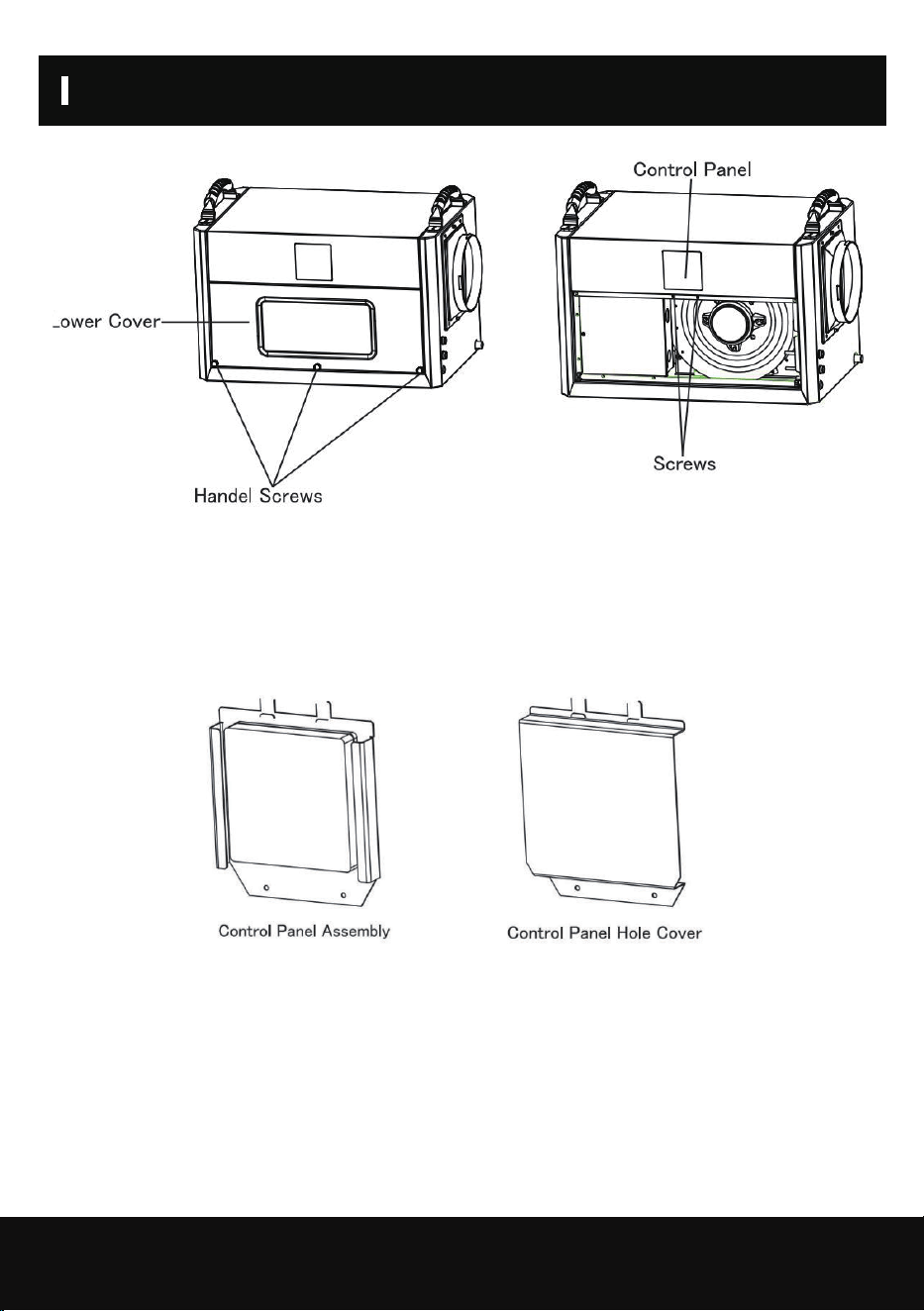
5.Wall assembly method for control panel
When the machine is shipped, the control panel is assembled on the front of the machine.
In order to facilitate the user to install the control panel on the wall, the control panel needs to be
removed and the control panel installed on a wall surface that is convenient for operation, as
follows.
a.Remove the 2 handle screws of the lower cover below the machine.
b.Pinch the handle screws in the middle of the front panel below with your hands and pull
outward with gentle force to pull the front panel apart.
11
INSTALLATION AND ASSEMBLY OF ACCESSORIES
c.screwdriver to screw down the 2 fixed screws and remove the control panel assembly, then
install the cover in the location of the control panel of the machine and fix it with 2 screws.
d.Remove the upper cover of the control panel assembly with a screwdriver; then remove the 2
screws and remove the lower cover.
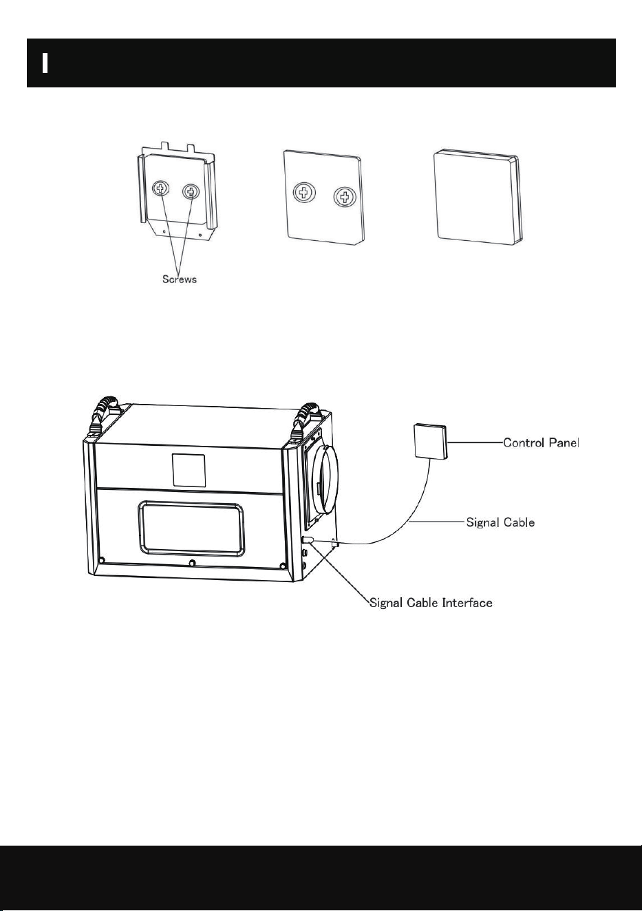
e.Mount the lower cover of the control panel assembly on a wall where it can be easily operated.
f.Connect the signal wires to the terminals of the control panel inside the upper cover of the
control panel assembly, install them in place, and then fix the upper cover on the lower cover.
12
INSTALLATION AND ASSEMBLY OF ACCESSORIES
g.Then plug the other end of the signal cable of the control panel into the signal interface of the
machine.
DRAINAGE METHOD
13
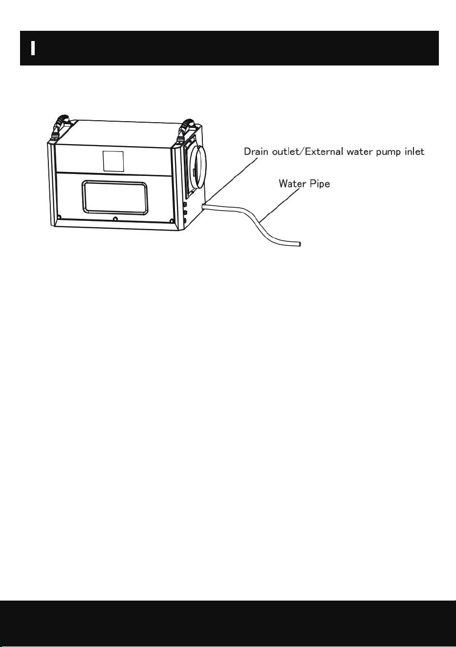
1.Water pipe drainage method
Operation instructions: When using the water pipe drainage method, connect the water pipe at
the drain, place the water pipe in place, place the other end of the water pipe at the drain, or at
the drain sink,or in the water storage container; turn on the machine to use the water pipe
drainage method.
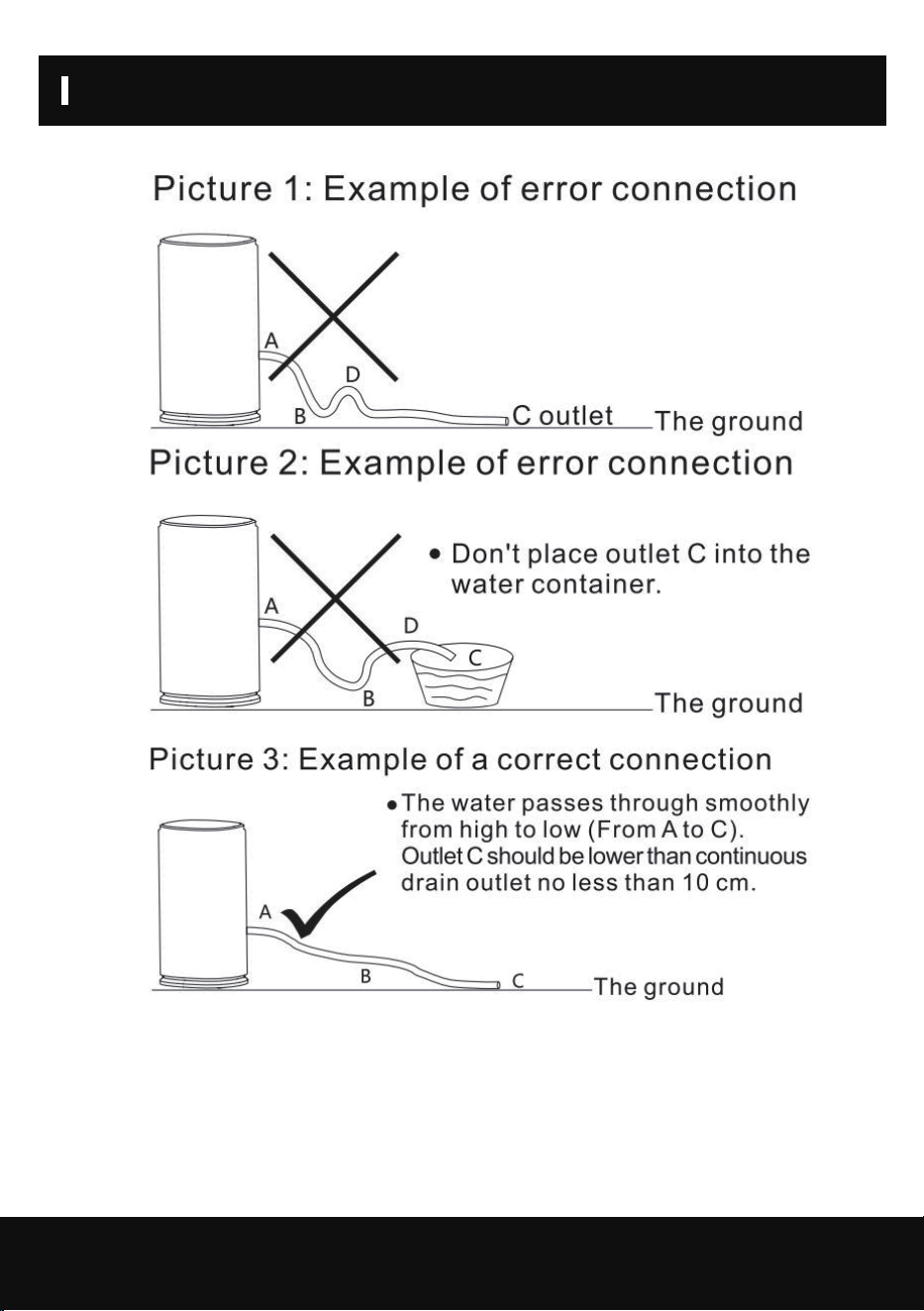
Continuous drainage pipe instructions
Dehumidifiers Adopt Drain by Gravity, the collected condensation water can be drained by
gravity.When using gravity to drain:
(1) Connect the drain hose to the Gravity Drain Outlet;
(2) Place the unattached end of the hose in a suitable drainage facility. The drainage facility
should be lower than the drain outlet of the dehumidifier. (Ensure there are no kinks or other
obstructions that will stop the water to flow.)
Note:
(1) If you use a bucket or other container for water collection,check it regularly to prevent
overflows.
(2) Connecting a drain hose that is too long is not recommended,as it may cause water to back
up, causing a leak.
(3) lf the drain hose is too long, water may not drain completely.which can lead to stagnant water
and mildew building up inside the hose.
(4 Before moving the dehumidifier, make sure the condensed water inside is completely drained
to avoid water leakage.
DRAINAGE METHOD
14
DRAINAGE METHOD
15
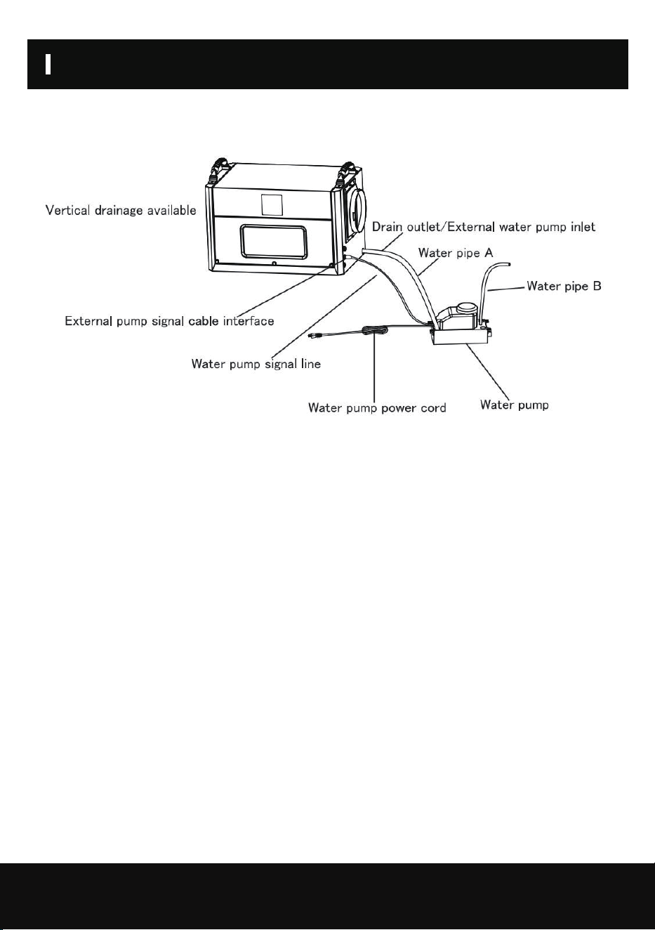
When it is necessary to connect an external water pump, one end of the drainpipe is connected to
the water outlet, and the other end is connected to the water inlet of the water pump.
Note:The reserved external water pump signal input port cannot be connected to the power
supply, so as not to cause the main board of the product to burn out.
Operating instructions: When using the pump drainage method, the operation is as follows.
1. The two ends of the water pipe A, one end connected to the machine drain, must be placed in
place; the other end placed in the water pump inlet, placed firmly.
2. Connect one end of the water pipe B to the water pump discharge port, and place the other
end of the water pipe in the sewer opening, or drainage sink, or water storage container; Note:
the length of the water pipe B must be within the range of the pump's head.
3. Plug one end of the pump signal line into the pump signal line interface of the machine and
assemble it in place.
4. Plug the power cord of the pump into a solid, suitable socket.Pump power on, turn on the
machine can be used to drain the water pump.
2.External pump drainage method(not include pump,need to buy)
CLEANING AND MAINTENANCE
16
Note: Before cleaning and maintaining the machine, please make sure to turn off the
machine and unplug it from the power source to prevent electric shock.
Cleaning :
Before doing any cleaning and maintenance work on the machine, the machine must be turned
off, unplugged, and no water should be spilled on the machine.
Use a soft, damp cloth to clean the casing. Do not use chemical solvents such as benzene, alcohol
or gasoline, otherwise, the machine casing will be damaged or
even deformed.
Filter cleaning:
The machine is equipped with a washable filter, it is recommended to clean the filter every 2
weeks. If the filter is blocked by dust, it will reduce the efficiency of the machine.
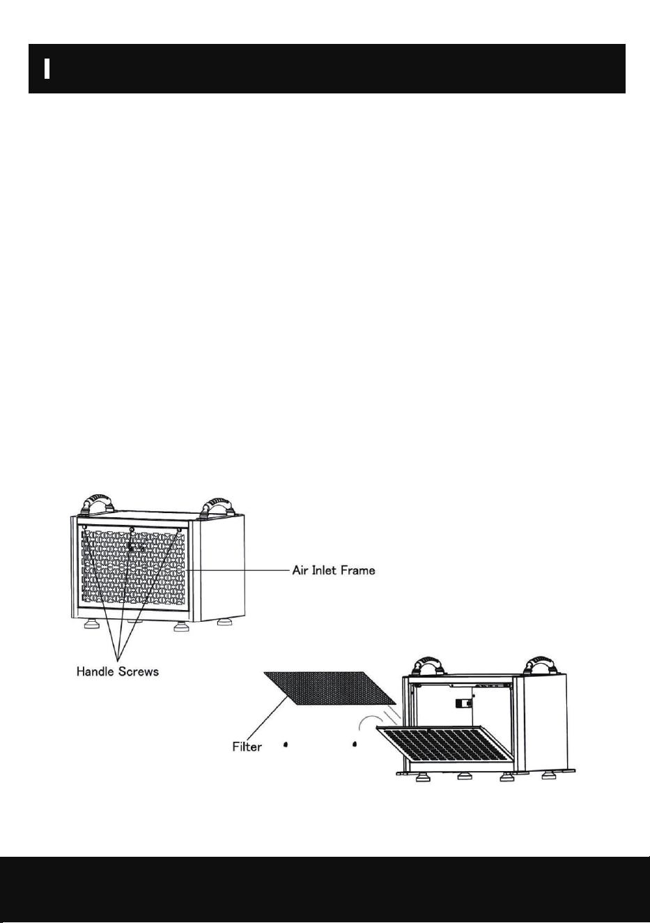
1.Cleaning the filter.
a.Remove the filter
(1) Remove the handle screws on both sides above the air inlet frame.
(2) Pinch the handle screws in the middle above the air inlet frame with your hands, pull outward
with a little force, and pull the air inlet frame rotate (such as the rotating arrow)
(3) Remove the filter.
CLEANING AND MAINTENANCE
17
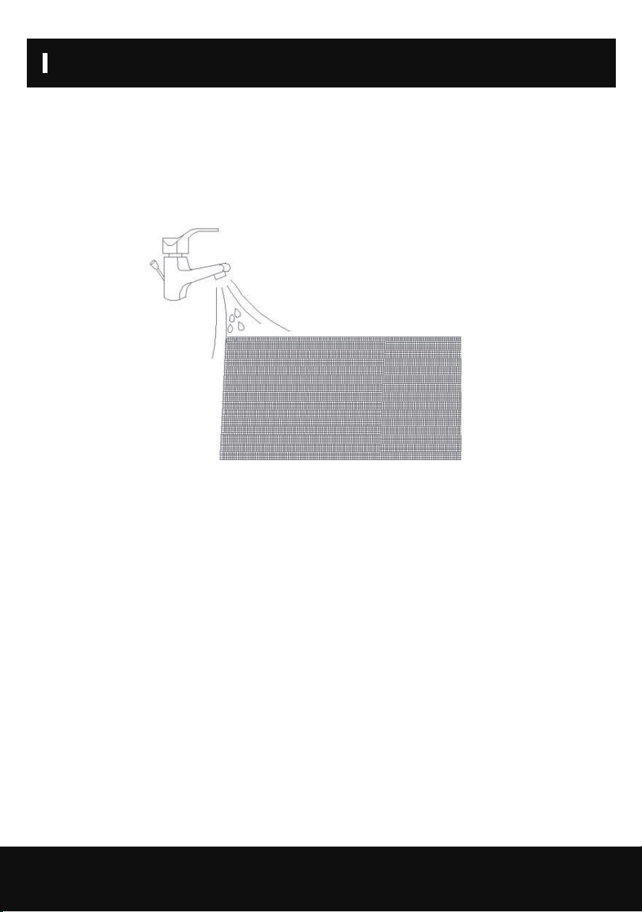
b.Clean the filter
Use a vacuum cleaner to gently absorb the dust on the surface of the filter. If the filter is very
dirty, you can use tap water to rinse the filter, and completely cool and dry it, then put it back
into the forward air sheet, which can improve the performance of the machine.
Suggestion: Clean the filter once after every 3 months of use.
c.Assemble the filter and air inlet frame
(1) The filter will be put into the assembly of the air inlet frame buckle position, need to be
assembled in place.
(2) The air inlet frame will be held up with force, the air inlet frame will be rotated and assembled
to the machine inside, which must be assembled in place.
(3) Lock the handle screws on both sides above the air inlet frame to fix it.
2.Machine body cleaning
Use a soft, slightly damp cloth to wipe the body.
3.Machine storage
When you do not use this product for a long time and intend to store it, pay attention to the
following steps.
a.Drain the water from the machine body.
b.Tidy up the power cord.
c.Clean the filter.
d.Place it in a fresh and dry environment.

18
SAFETY PRECAUTIONS ON SERVICING
Please follow these warnings when to undertake the following when servicing an appliance with R32.
1.Checks to the area
Prior to beginning work on systems containing flammable refrigerants,safety checks are
necessary to ensure that the risk of ignition is minimized. For repair to the refrigerating system, the
following precautions shall be complied with prior to conducting work on the system.
2.Work procedure
Work shall be undertaken under a controlled procedure so as to minimize the risk of a flammable gas
or vapor being present while the work is being performed.
3.General work area
All maintenance staff and others working in the local area shall be instructed on the nature of work
being carried out. Work in confined spaces shall be avoided. The area around the work space shall be
sectioned off. Ensure that the conditions within the area have been made safe by control of flamma-
ble material.
4.Checking for presence of refrigerant
The area shall be checked with an appropriate refrigerant detector prior to and during work, to
ensure the technician is aware of potentially flammable atmospheres. Ensure that the leak
detection equipment being used is suitable for use with flammable refrigerants,i.c. no sparking,ade-
quately sealed or intrinsically safe.
5.Presence of fire extinguisher
If any hot work is to be conducted on the refrigeration equipment or any associated parts, appropri-
ate fire extinguishing equipment shall be available to hand. Have a dry powder or CO2 fire
extinguisher adjacent to the charging area.
6.No ignition sources
No person carrying out work in relation to a refrigeration system which involves exposing any pipe
work that contains or has contained flammable refrigerant shall use any sources of ignition in such a
manner that it may lead to the risk of fire or explosion. All possible ignition sources, including
cigarette smoking,should be kept sufficiently far away from the site of installation, repairing,
removing and disposal, during which flammable refrigerant can possibly be released to the surround-
ing space. Prior to work taking place, the area around the equipment is to be surveyed to make sure
that there are no flam mable hazards or ignition risks."No Smoking"signs shall be displayed.
7.Ventilated area
Ensure that the area is in the open or that it is adequately ventilated before breaking into the
system or conducting any hot work.A degree of ventilation shall continue during the period that the
work is carried out. The ventilation should safely disperse any released refrigerant and preferably
expel it externally into the atmosphere.
8.Checks to the refrigeration equipment
Where electrical components are being changed,they shall be fit for the purpose and to the correct
specification. At all times the manufacturer's maintenance and service guidelines shall be followed.If
in doubt consult the manufacturer's technical department for assistance. The following checks shall
be applied to installations using flammable refrigerants:
-The charge size is in accordance with the room size within which the refrigerant containing parts are
installed;
-The ventilation machinery and outlets are operating adequately and are not obstructed.

19
TRANSPORTATION AND CUSTODY
During transportation, this product should be handled preciously to prevent violent vibration.
Generally, the packaged product should not be stored in the open air for a long time. It should be
placed in a well-ventilated, non-corrosive gas warehouse. It should not be placed upside down.
Set unit upright.Always store, transport, and use the unit in a horizontal position. If the unit is
ever placed in a vertical position, return it to the horizontal position and let it stand for at least
24 hours before turning it on.
Rainproof measures should be adopted when stored temporarily.For best results, operate your
dehumidifiers in an enclosed area. Place your dehumidifier away from obstructions, and keep it
away from anything that could block airflow into and out of the unit.

20
PRODUCT PAREMETERS
SKU ZX-DH-80-AZ-HM
Power Supply
Air Flow
Rated Input Current
Maxi Input Current
Refrigerant/Charge
Noise
Low Side Pressure
High Side Pressure
BCSC
Compressor Input
Fan Motor Power
80Pint/Day
110- 120V 60Hz
237CFM
6.6A
8.3A
R32/6.35oz
≤60dB(A)
260 Psi
550 Psi
15A
RLA:6.7A/LRA:35A
0.92A/0.133HP
ZX-DH-100-AZ-HM
100Pint/Day
110-120V 60Hz
237CFM
7.9A
11.0A
R32/9.18oz
≤60dB(A)
260 Psi
550 Psi
15A
RLA:6.7A/LRA:35A
0.92A/0.133HP
(80℉,60%RH)
Dehumidify Capacity
21
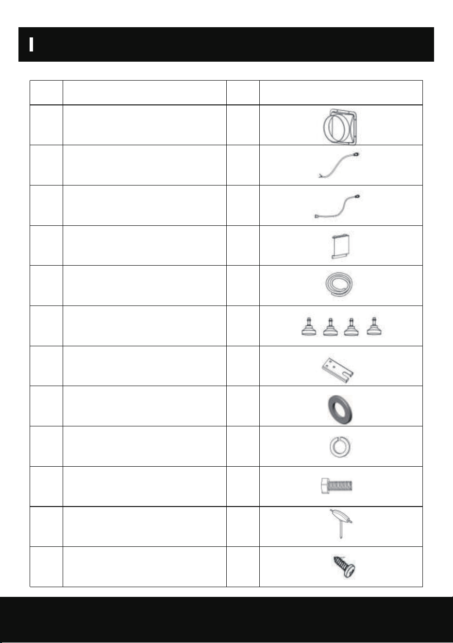
PACKING LIST
NO Part Name QTY PICTURE
1
2
3
4
5
6
7
8
9
10
11
12
1
1
1
1
1
4
4
12
12
12
1
4
Dust Adapter
Control Panel Hole Cover
Drain Pipe
Adjustable Feet
Ceiling Mount Gasket
Flat Washer
Spring Washers
Hexagon Head Screw
Hex Key
External Pump Full Water
Signal Input Cable
Control Panel External
Connection Cable
Cross Recessed
Pan Head Screw

Symptom Cause Solution
Machine Won't Run
Low Air Flow
Water Leakage
Loud Noise
Trouble Code:E1
Power outage
Restoration of power supply
Filter with dirt accumulation
Cleaning filters
The air inlet or outlet is blocked
Remove obstructions
Refrigerant leakage
Contact agent or manufacturer for
repail
Temperature and humidity
sensor failure
Check, or replace the
temperature and humidity sensor
Trouble Code:E2
Trouble Code:CL
Coil sensor failur
When the ambient temperature Tr< 36 ℉ , "CL" will be displayed and the
compressor will stop immediately, and the fan delay will be executed according
to the set value (F1 default 0, delay 5 seconds to stop)When the ambient
temperature rises to 2 39℉ , normal operation will resume.
Trouble Code:CH
When the ambient temperature Tr> 113 ℉ , "CH" will be displayed, the
compressor will stop immediately, and the fan delay will be executed according
to the set value (F1 default 0, delay 5 seconds to stop)when the ring
temperature s 108℉, normal operation will be resumed.
Trouble Code:LO
When the ambient humidity Hr< 20%, "LO" will be displayed, the compressor
will stop immediately, and the fan delay will be executed according to the set
value (F1 default 0, delay 5 seconds to stop). After the humidity rises > 20%,
resume normal work.
Trouble Code:HI
When the ambient humidity Hr>95%, "Hl" is displayed and the compressor and
fan work normally.After the humidity falls back to <95%, it will resume normal
operation
Check, or replace the coil sensor
Machine Is Not level
Move the dehumidifier to flat,
firmground
Filter Mesh is Blocked
Clean the filter mesh
accordinotoinstructions listed in manual
Clogged outlet pipe
Remove the panel to remove
theblockage at the water pipe or
wateroutlet
Power plug is not
connected well
Room temperature over 113℉
or below 38℉
The machine's protection device isactivated
so that the machine does notrun
Connect the plug to the socket
22
TROUBLESHOOTING

This product is covered by a 12-month product and warranty from the date of initial purchase in
case of any problems, please contact the Customer Service Center via the contact information listed
in this User Guide.
Our warranty covers replacement products by repairing or replacing any defective parts and labor
necessary to bring it up to its original specifications, and we can provide a replacement product
instead of repairing the defective product. Our sole obligation under this warranty is limited to such
repair or replacement.
Any claim will require a receipt showing the date of purchase, so please keep all receipts in a safe
place. While greatly appreciated, product registrant is not required to activate any warranty and
product registration does not eliminate the need for proof of original purchase. The warranty will be
voided if repairs are performed by a non-authorized third party and/or if spare parts other than
those provided by us are used, These are the general terms of our warranty service, but we always
urge our customers to contact us ([email protected]) with any questions they may have,
regardless of the terms of the warranty.
WARRANTY AND SERVICE
23
WARRANTY AND SERVICE