GARMIN AIS
™
800
INSTALLATION INSTRUCTIONS
Important Safety Information
WARNING
See the Important Safety and Product Information guide in the product box for product warnings and other
important information.
CAUTION
To avoid possible personal injury, always wear safety goggles, ear protection, and a dust mask when drilling,
cutting, or sanding.
To avoid possible personal injury or damage to the device and vessel, disconnect the vessel's power supply
before beginning to install the device.
To avoid possible personal injury or damage to this device and vessel, only install this device when the vessel is
on land, or when properly secured and docked in calm water conditions.
NOTICE
When drilling or cutting, always check what is on the opposite side of the surface to avoid damaging the vessel.
FCC Compliance
NOTICE
In the USA, it is prohibited under FCC regulations to enter incorrect or improper data, and it is prohibited for any
person other than the manufacturer or the installing dealer to input an MMSI number.
It is a violation of the rules of the FCC to input an MMSI number that has not been properly assigned to the user,
or to otherwise input any inaccurate data in this device.
Assigning Data to the Device
WARNING
When programmed with a valid MMSI number, this device allows you to transmit AIS signals with vessel
position data. This device is meant to enhance situational awareness and may not prevent vessel collisions in
all circumstances. It is your obligation to be aware of your surroundings and to ensure safe operation of the
vessel.
CAUTION
You must program the Garmin AIS 800 device with a valid vessel MMSI number before installing the device
on your boat. By default, the device operates in silent mode until you program the device with a valid vessel
MMSI number. In silent mode, the device receives, but does not transmit, AIS signals with position data. You
can program the device to transmit static vessel data including the vessel name, call sign, type, and dimensions,
including the location of the vessel's GPS antenna.
You can program the device to transmit vessel position data and static vessel data including the vessel name,
call sign, type, dimensions, and the location of the vessel's GPS antenna. It is also possible to temporarily revert
to silent mode (only receives, but does not transmit, vessel data) by means of a toggle switch (not included)
(Connecting the Device to Power, page5).
GUID-61A42529-ECEC-4B79-9F77-A5D87D90A579 v7
May 2024

Installing the Garmin AIS 800 Software on Your Computer
1 Go to garmin.com/AIS800, select Software, and download the .zip file to your computer.
2 Connect the included USB cable to your computer and the USB port on the Garmin AIS 800 device.
NOTE: While you program with the USB cable, you may need to disconnect all other cables from the Garmin
AIS 800 device to prevent a ground loop between the computer and your vessel power.
3 Double-click the .exe file, and follow the on-screen instructions.
Programming the Garmin AIS 800
Before the device can be used on a boat, it must be programmed with a unique MMSI number and with
additional vessel-specific static data. The MMSI number must be programmed by an authorized marine
electronics dealer or installer.
Before you can program the device, you must install the Garmin AIS 800 software on your computer (Installing
the Garmin AIS 800 Software on Your Computer, page2).
1 In the program, select the Static data tab.
2 In the Connection and Status window, select a COM port from the drop-down list.
3 Select Connect.
4 Enter your ship name, call sign, dimensions, vessel type, and MMSI number (Assigning an MMSI Number to
the Garmin AIS 800, page2).
5 Select Save data to AIS 800.
NOTE: The data is lost if the Garmin AIS 800 device is turned off. You must select Save data to AIS 800 to
permanently save your data.
6 Select File > Exit.
Assigning an MMSI Number to the Garmin AIS 800
1 Launch the Garmin AIS 800 setup software.
2 In the Connection and Status window, select a COM port from the drop-down list.
3 Select Connect.
4 In the Static Data window, enter your nine-digit MMSI number in the MMSI Number field.
NOTICE
You cannot change the MMSI number after you assign the MMSI number to your boat. If you assign an incorrect
MMSI number, you must return the device to the manufacturer for a factory reset.
5 Select Save data to AIS 800.
Tools Needed
• Drill
• Drill bits appropriate for the surface and hardware
• Phillips screwdriver
• Pencil
2

Mounting Considerations
NOTICE
This device should be mounted in a location that is not exposed to extreme temperatures or conditions. The
temperature range for this device is listed in the product specifications. Extended exposure to temperatures
exceeding the specified temperature range, in storage or operating conditions, may cause device failure.
Extreme-temperature-induced damage and related consequences are not covered by the warranty.
• You must mount the device in a location where it will not be submerged.
• You must mount the device in a location with adequate ventilation where it will not be exposed to extreme
temperatures.
For optimal internal GPS reception:
• You should mount the device in a location where it is above the water line when the ship is in the water.
• You should mount the device as far as possible, at least 20cm (7.9in.), from cables, electronics, metal
objects, and other potential sources of GPS interference.
• If you mount the device in a boat with a metal hull, you must connect the device to an external GPS antenna
(sold separately).
• If possible, you should mount the device horizontally, with the face of the device pointing upward or vertically
with the LEDs facing upward. The GPS is most sensitive in these positions.
VHF Antenna Mounting and EME Exposure
WARNING
Radio operators with cardiac pacemakers, life-support machines, or electrical medical equipment should not be
exposed to excessive radio-frequency (RF) fields, because the RF field may interfere with the function of their
medical equipment.
CAUTION
This device generates and radiates radio frequency (RF) electromagnetic energy (EME). Failure to observe these
guidelines may expose people to RF radiation absorption exceeding the maximum permissible exposure (MPE).
Garmin
®
declares an MPE radius of 2.48m (97.64in.) for this system, which was determined using 5 W output
to an omni-directional, 6dBi gain antenna. The antenna should be installed to maintain a distance of 2.48m
(97.64in.) between the antenna and all people.
Mounting the Device
NOTICE
If you are mounting the device in fiberglass, when drilling the pilot holes, use a countersink bit to drill a
clearance counterbore through only the top gel-coat layer. This will help to avoid cracking in the gel-coat layer
when the screws are tightened.
Before you mount the device, you must select a mounting location and determine the mounting hardware
needed for the surface.
NOTE: Mounting hardware is included with the device, but it may not be suitable for the mounting surface.
1 Place the device in the mounting location and mark the location of the pilot holes.
2 Using a bit appropriate for the surface and the mounting hardware, drill a pilot hole for one corner of the
device.
3 Loosely fasten the device to the surface with one corner and examine the other three pilot-hole marks.
4 Mark new pilot-hole locations if necessary.
5 Remove the device from the mounting surface.
6 Drill the appropriate pilot holes for the other three marks.
7 Secure the device to the mounting location.
3
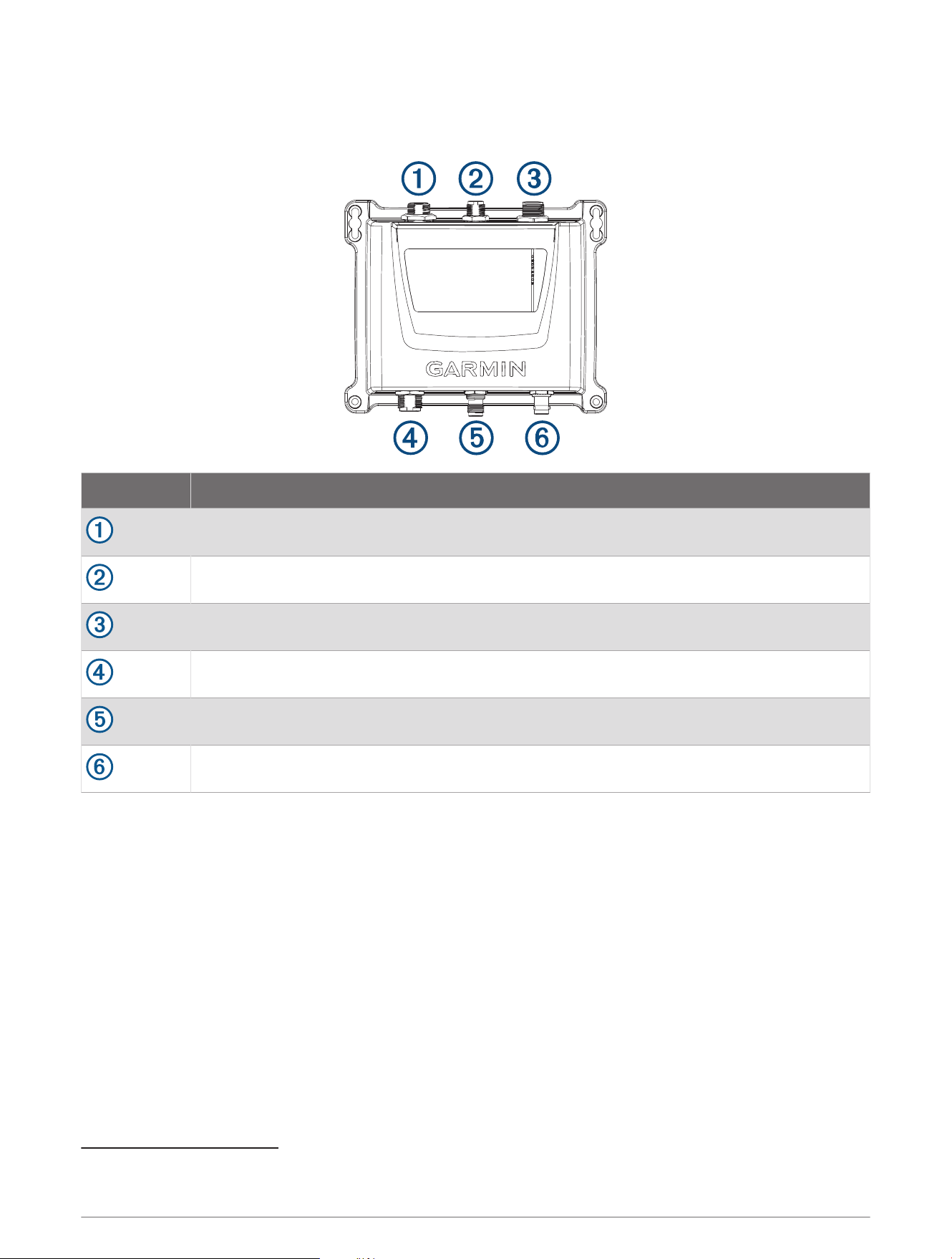
Connection Considerations
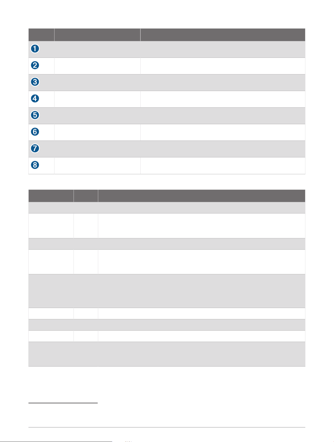
Device Ports
Item Description
USB port
1
NMEA 2000
®
Power and NMEA
®
0183
AIS antenna (required, not included)
VHF radio (optional)
External GPS antenna (optional)
2
1
Used with the included USB cable when connecting to a computer to program the device
2
An external GPS antenna is required when the device is installed in a location where it cannot receive GPS signals, especially in metal-hulled vessels.
4
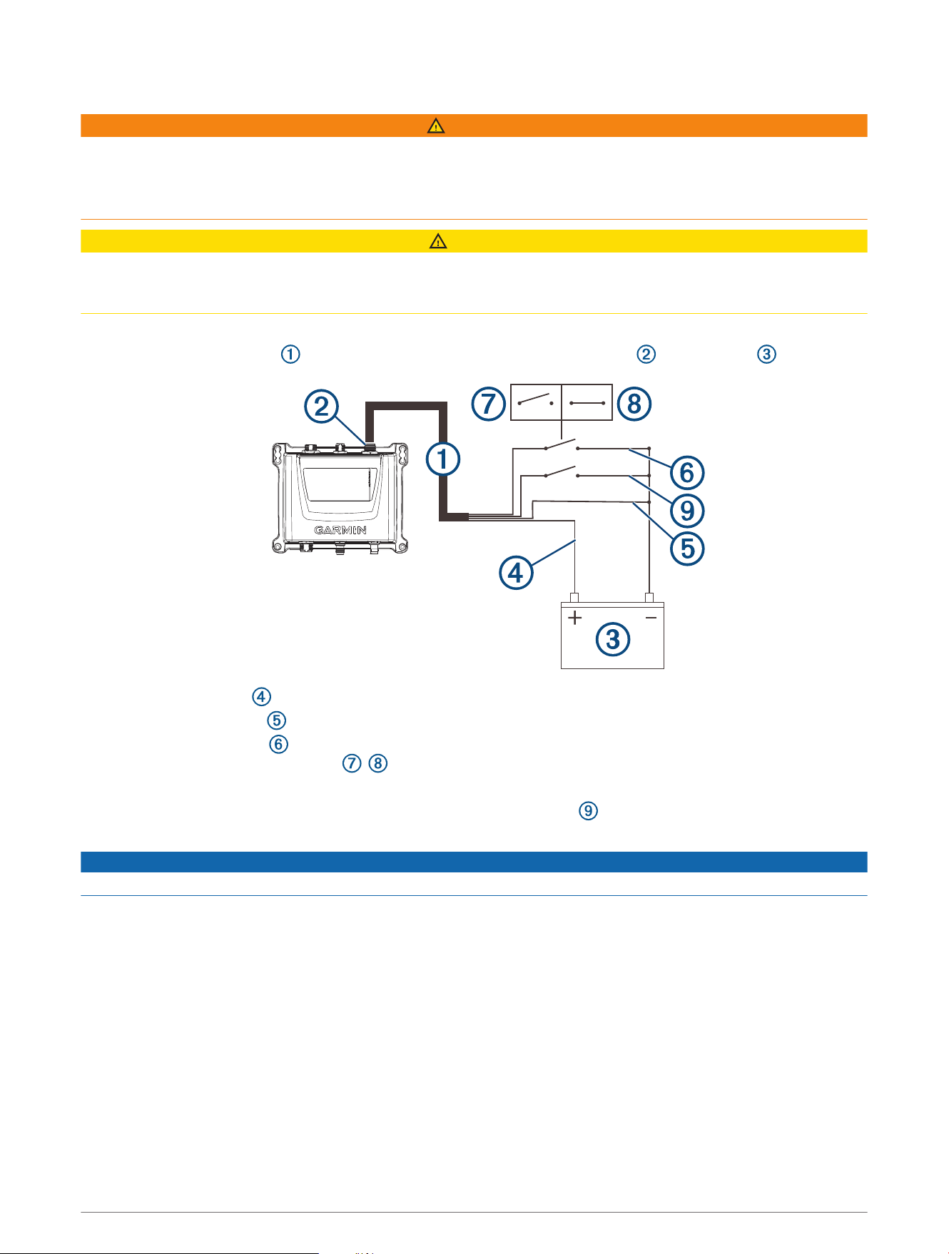
Connecting the Device to Power
WARNING
When programmed with a valid MMSI number, this device allows you to transmit AIS signals with vessel
position data. This device is meant to enhance situational awareness and may not prevent vessel collisions in
all circumstances. It is your obligation to be aware of your surroundings and to ensure safe operation of the
vessel.
CAUTION
After installing the device and programming a valid vessel MMSI number, you can temporarily revert to the
default silent mode (only receives, does not transmit) using a toggle switch (not included) (Connecting the
Device to Power, page5). While operating in silent mode, the device does not transmit AIS signals.
Four wires (red, black, green, and yellow) provide the basic power connection.
1 Route the wiring harness from the device POWER (and NMEA 0183) port to the battery .
2 Connect the red wire to the positive (+) battery terminal.
3 Connect the black wire to the power ground on the negative (-) battery terminal.
4 Connect the green wire to the power ground with a switch (not included) between the green wire and
power ground, to provide a toggle , switch to revert to the default silent mode (optional).
5 Complete an action, based on the network type:
• In a NMEA 0183 system, connect the yellow wire (Accessory On) to the power ground, and install a
switch (not included) between the yellow wire and the power ground.
NOTICE
Turning off the switch prevents the device from draining the battery when the engine is off.
• In a NMEA 2000 system, the device automatically powers on and off with the system, and you do not need
to connect the yellow Accessory On wire.
5
Connecting an AIS Antenna
To transmit and receive signals, you must connect an external AIS antenna (not included) to the Garmin AIS 800
device.
For the best performance, you should use an AIS-specific antenna or a VHF antenna that is well-tuned at the AIS
end of the band (VSWR 2:1 or less at 162MHz).
The device has an internal antenna splitter that allows sharing the same antenna with a VHF radio. When
sharing the antenna, you cannot receive AIS updates while transmitting on the VHF radio.
1 Mount the antenna (not included) according to the installation instructions provided with the antenna.
2 Connect the antenna cable to the VHF ANT port.
3 Optionally, connect a VHF interconnect cable (sold separately, part number 010-12824-01) to the VHF RADIO
port on the Garmin AIS 800 device and to the antenna port on a VHF radio to share the antenna with the VHF
radio.
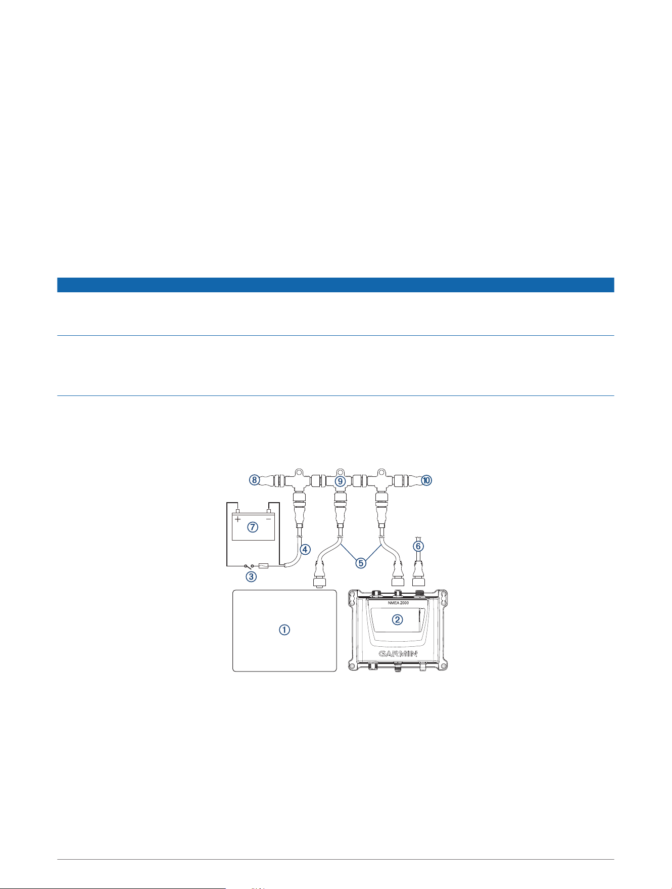
NMEA 2000 Connections
NOTICE
If you are installing a NMEA 2000 power cable, you must connect it to the boat ignition switch or through
another in-line switch. NMEA 2000 devices will drain your battery if the NMEA 2000 power cable is connected to
the battery directly.
If you are connecting to an existing NMEA 2000 network, identify the NMEA 2000 power cable. Only one NMEA
2000 power cable is required for the NMEA 2000 network to operate properly.
A NMEA 2000 Power Isolator (010-11580-00) should be used in installations where the existing NMEA 2000
network manufacturer is unknown.
This device is not powered through the NMEA 2000 network. You must connect the device to a power source
(Connecting the Device to Power, page5).
If you are unfamiliar with NMEA 2000, you should read the Technical Reference for NMEA 2000 Products at
garmin.com/manuals/nmea_2000.
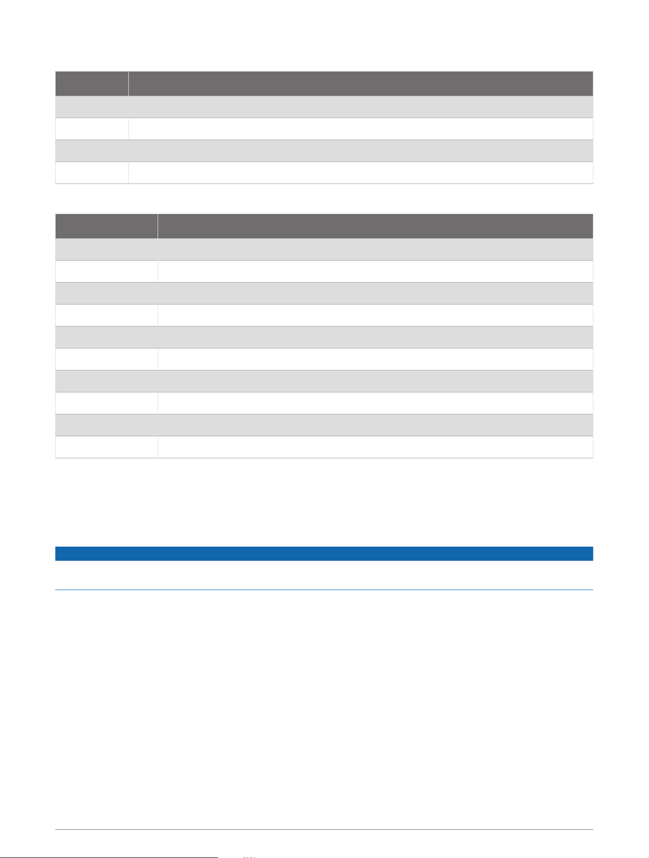
6
Item Description
Compatible NMEA 2000 chartplotter or other device
Garmin AIS 800 device
Ignition or in-line switch
NMEA 2000 power cable
NMEA 2000 drop cable
Garmin AIS 800 device power connection (Connecting the Device to Power, page5)
12Vdc power source
NMEA 2000 terminator or backbone cable
NMEA 2000 T-connector
NMEA 2000 terminator or backbone cable
7
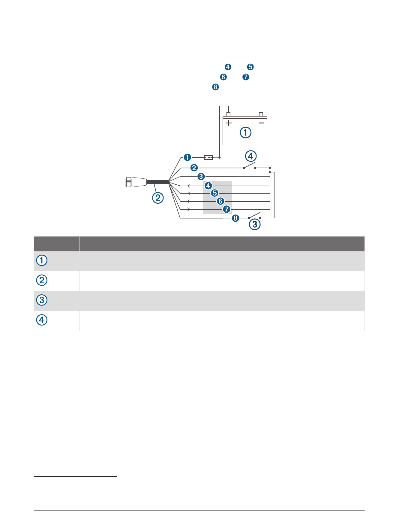
NMEA 0183 Device Connections
This diagram illustrates two-way connections for both sending and receiving data. You can also use this
diagram for one-way communication.
To receive information from a NMEA 0183 device, refer to items and when connecting the Garmin device.
To transmit information to a NMEA 0183 device, refer to items and when connecting the Garmin device.
For either NMEA 2000 or NMEA 0183 systems, refer to item when making the basic power connections
(Assigning Data to the Device, page1), (Connecting the Device to Power, page5).
Item Description
12 Vdc power source
Power/NMEA 0183 cable
Optional switch (not included)
3
Accessory On switch (not included)
4
3
Connecting the green wire to the power ground with a switch (not included) provides a toggle to temporarily revert to silent mode (receives only, does not
transmit).
4
In NMEA 0183 systems, use the switch to power off the device when the boat engine is off, to avoid draining the battery.
8
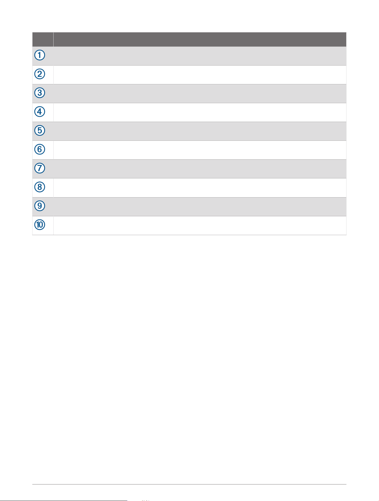
Wire Garmin Wire Color Garmin Wire Function
Red Power
Yellow Accessory On (NMEA 0183 systems)
Black Power ground
Purple RxA (+)
Gray RxB (-)
Blue TxA (+)
Brown TxB (-)
Green Silent mode (optional)
5
Status LEDs
LED State Description
VHF TX Solid A connected VHF radio is transmitting.
Error Solid
The device has encountered a critical error. You can connect the device to a
computer, and use the Garmin AIS 800 setup software to view detailed informa
tion about the warning condition.
SRM Flashing Reserved for future use.
Warning Solid
The device detects a warning condition. You can connect the device to a
computer, and use the Garmin AIS 800 setup software to view detailed informa
tion about the warning condition.
RX Only Solid
The device is in silent mode or not ready to transmit.
NOTE: The Garmin AIS 800 device does not transmit without a GPS signal or an
MMSI number, when the AIS base station commands a quiet time, or when the
device encounters a critical error.
TX Flashing The device is sending an AIS message.
RX Flashing The device is receiving an AIS message.
Power Solid The device is ready to transmit and receive.
VHF TX, Error,
Warning, and
Power.
Solid
When these four LEDs are illuminated, the device is connected only to a computer
for programming by a USB cable.
5
Connecting the green wire to the power ground with a switch (not included) provides a toggle to temporarily revert to silent mode (receives only, does not
transmit).
9

Connecting the Device to a Remote GPS Antenna
This device must receive GPS information for proper functionality. The device includes an internal GPS antenna.
If your mounting location does not provide good GPS reception, you can install a remote GPS antenna (not
included) and connect it to the device.
1 Follow the instructions provided with your external GPS antenna to install it on your boat correctly.
2 Route the GPS antenna cable to the back of your device, away from sources of electrical interference.
3 Connect the GPS antenna cable to the GPS ANT port on your device.
Appendix
Specifications
Dimensions (W x H x D) 175 x 142.3 x 54.5mm (6.9 x 5.6 x 2.1in.)
Weight 414g (0.9lbs.)
Operating temperature range From -15° to 55°C (from 5° to 131°F)
Storage temperature range From -20° to 75°C (from -4° to 167°F)
Water rating IEC 605290 IPX7
6
Power input 12 to 24Vdc, 2A max.
Current draw
12Vdc: less than 400mA
24Vdc: less than 250mA
Fuse 5 A, 125V fast-acting
NMEA 2000 LEN @ 9 Vdc 2
Transmit power 5W Class B, SOTDMA (1W remote switchable by authorities)
Antenna port impedance 50ohm
Wireless frequency/protocol 162MHz @ 38dBm maximum
Compass-safe distance 40cm (15
3
/
4
in.)
6
The device withstands incidental exposure to water of up to 1m for up to 30min. For more information, go to www.garmin.com/waterrating.
10

NMEA 2000 PGN Information
Transmit
PGN Description
059392 ISO acknowledgment
060928 ISO address claim
126208 NMEA: Command, request, acknowledge group function
126464 PGN list
126992 System time
126993 Heartbeat
126996 Product information
126998 Configuration information
129025 Position rapid update
129026 COG/SOG rapid update
129029 GNSS position
129038 AIS class A position report
129039 AIS class B position report
129040 AIS class B extended position report
129041 AIS aids to navigation (AtoN) report
129539 GNSS DOPs (dilution of precision)
129540 GNSS satellites in view
129793 AIS UTC and date report
129794 AIS class A static and voyage related data
129795 AIS addressed binary message
129797 AIS binary broadcast message
129798 AIS SAR aircraft position report
129801 AIS addressed safety related message
129802 AIS safety related broadcast message
129809 AIS class B "CS" static data report, part A
129810 AIS class B "CS" static data report, part B
11
Receive
PGN Description
059392 ISO acknowledgment
059904 ISO request
060928 ISO address claim
126208 NMEA: Command, request, acknowledge group function
NMEA 0183 Sentences Supported
Sentence Definition
ACA AIS Regional Channel Assignment Message
ALR Set alarm state
GGA Global positioning system fix data
RMC Recommended minimum specific GNSS data
SSD AIS ship static data
TXT Text transmission, general purpose
VDM AIS VHF data-link message
VDL AIS VHF data-link own-vessel report
VER Version
VSD AIS voyage static data
Testing for Interference from LED Lights
LED lighting from sources such as navigation lights, searchlights, floodlights, interior and exterior lights, and
adornments can interfere with your Garmin AIS 800 device. Radio interference can cause poor reception, jam
radio signals, and create a safety hazard in emergency situations. You should test for LED interference before
mounting the VHF antenna.
NOTICE
If your LED lights interfere with the Garmin AIS 800 device, you must mount the VHF antenna farther away from
the LED lights, or use non-jamming lights.
1 Turn off all LED lights.
2 Turn on your chartplotter and Garmin AIS 800 device.
3 Observe the moving AIS targets on the chartplotter screen for at least one minute.
4 Turn on all LED lights.
5 Observe the moving AIS targets on the chartplotter screen for at least one minute.
If most of the moving AIS targets disappear from the screen, the LED lights interfere with the Garmin AIS 800
device reception.
12
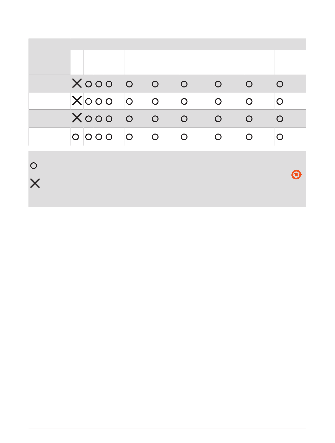
物質宣言
部件名称
有毒有害物质或元素
铅 汞 镉 六价铬 多溴联苯
多溴二苯
醚
邻苯二甲酸
二(2-乙基
己)酯
邻苯二甲
酸丁苄酯
邻苯二甲
酸二丁酯
邻苯二甲酸
二异丁酯
印刷电路板组
件
金属零件
电缆 电缆组件
连接器
塑料和橡胶零
件
本表格依据 SJ/T11364 的规定编制。
: 代表此种部件的所有均质材料中所含的该种有害物质均低于
(GB/T26572) 规定的限量
: 代表此种部件所用的均质材料中, 至少有一类材料其所含的有害物质高于
(GB/T26572) 规定的限量
* 该产品说明书应提供在环保使用期限和特殊标记的部分详细讲解产品的担保使用条件。
产品
联系信息
制造厂商 : ASSDEV GmbH
销售厂商 : 上海佳明航电企业管理有限公司
联络地址 : 上海市徐汇区桂平路 391 号 ( 新漕河泾国际商务中心 A 座 37 层 )
电 话 : 021-60737675
客服专线 : 400-819-1899
© 2018 Garmin Ltd. or its subsidiaries
Garmin
®
and the Garmin logo are trademarks of Garmin Ltd. or its subsidiaries, registered in the USA and other countries. These trademarks may not be used without the
express permission of Garmin.
NMEA
®
, NMEA 2000
®
, and the NMEA 2000 logo are registered trademarks of the National Marine Electronics Association.
13

© 2018 Garmin Ltd. or its subsidiaries
support.garmin.com