
Beam Cutter Kit
Model
HA25-BC12
WARNING: To prevent serious injury, User must read and
understand Owner’s Manual. SAVE THIS MANUAL.
When unpacking, make sure that the product is intact and undamaged.
If any parts are missing or broken, please call 1-888-866-5797
as soon as possible. Reference 58804.
Owner’s Manual &
Safety Instructions
REV 22i

Page 2 For technical questions, please call 1-888-866-5797. Item 58804
IMPORTANT SAFETY INFORMATION
GENERAL POWER TOOL SAFETY WARNINGS
Read all safety warnings and all instructions.
Failure to follow the warnings and instructions may
result in electric shock, fire and/or serious injury.
Save all warnings and instructions
for future reference.
The term “power tool” in the warnings refers
to your mains-operated (corded) power tool
or battery-operated (cordless) power tool.
Work Area Safety
1. Keep work area clean and well lit.
Cluttered or dark areas invite accidents.
2. Do not operate power tools in explosive
atmospheres, such as in the presence of
flammable liquids, gases or dust. Power tools
create sparks which may ignite the dust or fumes.
3. Keep children and bystanders
away while operating a power tool.
Distractions can cause you to lose control.
Personal Safety
1. Stay alert, watch what you are doing and use
common sense when operating a power tool. Do
not use a power tool while you are tired or under
the influence of drugs, alcohol or medication.
A moment of inattention while operating power
tools may result in serious personal injury.
2. Use personal protective equipment. Always
wear eye protection. Protective equipment
such as dust mask, non-skid safety shoes, hard
hat, or hearing protection used for appropriate
conditions will reduce personal injuries.
3. Prevent unintentional starting. Ensure the
switch is in the off-position before connecting
to power source and/or battery pack, picking
up or carrying the tool. Carrying power tools
with your finger on the switch or energizing power
tools that have the switch on invites accidents.
4. Remove any adjusting key or wrench
before turning the power tool on. A wrench
or a key left attached to a rotating part of the
power tool may result in personal injury.
5. Do not overreach. Keep proper footing and
balance at all times. This enables better control
of the power tool in unexpected situations.
6. Dress properly. Do not wear loose clothing or
jewelry. Keep your hair, clothing and gloves
away from moving parts. Loose clothes, jewelry
or long hair can be caught in moving parts.
7. If devices are provided for the connection of
dust extraction and collection facilities, ensure
these are connected and properly used. Use of
dust collection can reduce dust-related hazards.
8. Do not let familiarity gained from frequent use
of tools allow you to become complacent and
ignore tool safety principles. A careless action
can cause severe injury within a fraction of a second.
9. Only use safety equipment that has been
approved by an appropriate standards agency.
Unapproved safety equipment may not
provide adequate protection. Eye protection
must be ANSI-approved and breathing
protection must be NIOSH-approved for
the specific hazards in the work area.
10. Do not leave the tool unattended when it
is plugged into an electrical outlet and/
or the Battery Pack is connected. Turn off
the tool, and unplug it from its electrical outlet
or remove the Battery Pack before leaving.
11. This product is not a toy.
Keep it out of reach of children.
12. People with pacemakers should consult their
physician(s) before use. Electromagnetic fields
in close proximity to heart pacemaker could cause
pacemaker interference or pacemaker failure.
In addition, people with pacemakers should:
• Avoid operating alone.
• Do not use with Trigger locked on.
• Properly maintain and inspect to avoid
electrical shock.
• Properly ground power cord.
Ground Fault Circuit Interrupter (GFCI)
should also be implemented – it prevents
sustained electrical shock.
13. The warnings, precautions, and instructions
discussed in this instruction manual cannot
cover all possible conditions and situations
that may occur. It must be understood by the
operator that common sense and caution are
factors which cannot be built into this product,
but must be supplied by the operator.

Page 3For technical questions, please call 1-888-866-5797.Item 58804
Power Tool Use and Care
1. Do not force the power tool. Use the correct
power tool for your application. The correct
power tool will do the job better and safer
at the rate for which it was designed.
2. Do not use the power tool if the Trigger
does not turn it on and off. Any power tool
that cannot be controlled with the Trigger
is dangerous and must be repaired.
3. Disconnect the plug from the power source and/
or remove the battery pack, if detachable, from
the power tool before making any adjustments,
changing accessories, or storing power
tools. Such preventive safety measures reduce
the risk of starting the power tool accidentally.
4. Store idle power tools out of the reach of
children and do not allow persons unfamiliar
with the power tool or these instructions
to operate the power tool. Power tools are
dangerous in the hands of untrained users.
5. Maintain power tools and accessories.
Check for misalignment or binding of moving
parts, breakage of parts and any other
condition that may affect the power tool’s
operation. If damaged, have the power tool
repaired before use. Many accidents are
caused by poorly maintained power tools.
6. Keep cutting tools sharp and clean. Properly
maintained cutting tools with sharp cutting edges
are less likely to bind and are easier to control.
7. Use the power tool, accessories and tool bits
etc. in accordance with these instructions,
taking into account the working conditions
and the work to be performed. Use of the
power tool for operations different from those
intended could result in a hazardous situation.
8. Keep handles and grasping surfaces dry, clean
and free from oil and grease. Slippery handles
and grasping surfaces do not allow for safe handling
and control of the tool in unexpected situations.
Service
1. Have your power tool serviced by a
qualified repair person using only identical
replacement parts. This will ensure that the
safety of the power tool is maintained.
2. Maintain labels and nameplates on the tool.
These carry important safety information.
If unreadable or missing, contact
Harbor Freight Tools for a replacement.
Chain Saw Safety Warnings
1. Keep all parts of the body away from the saw
chain when the saw is operating. Before you
start the saw, make sure the saw chain is not
contacting anything. A moment of inattention
while operating chain saws may cause entanglement
of your clothing or body with the saw chain.
2. Always hold the saw with your dominant
hand on the rear handle and your weak hand
on the front handle. Holding the saw with a
reversed hand configuration increases the risk
of personal injury and should never be done.
3. Hold the power tool by insulated gripping
surfaces only, because the saw chain may
contact hidden wiring or its own cord.
Saw chains contacting a “live” wire may make
exposed metal parts of the power tool “live” and
could give the operator an electric shock.
4. Wear safety glasses and hearing protection.
Further protective equipment for head, hands,
legs and feet is recommended. Adequate
protective clothing will reduce personal injury by
flying debris or accidental contact with the saw chain.
5. Do not operate a beam saw in a tree,
from a ladder, rooftop, or any unstable
support. Operation of a chain saw in this
manner may result in personal injury.
6. Always keep proper footing and operate
the saw only when standing on fixed,
secure and level surface. Slippery or
unstable surfaces such as ladders may cause
a loss of balance or control of the saw.
7. Carry the saw by the front / auxiliary handle
with the chain saw switched off and away
from your body. Proper handling of the chain
saw will reduce the likelihood of accidental
contact with the moving saw chain.
8. Follow instructions for lubricating, chain
tensioning and changing accessories.
Improperly tensioned or lubricated chain may
either break or increase the chance for kickback.
9. Keep handles dry, clean, and free from
oil and grease. Greasy, oily handles
are slippery causing loss of control.
10. Cut wood only. Do not use chain saw for
purposes not intended. For example: do not use
chain saw for cutting plastic, masonry or non-
wood building materials.
Use of the chain saw for operations different than
intended could result in a hazardous situation.

Page 4 For technical questions, please call 1-888-866-5797. Item 58804
11. Causes and operator prevention of kickback:
Kickback may occur when the nose or tip of the
guide bar touches an object, or when the wood
closes in and pinches the saw chain in the cut.
Tip contact in some cases may cause
a sudden reverse reaction, kicking the
guide bar up and back towards the operator.
Pinching the saw chain along the
top of the guide bar may push the guide
bar rapidly back towards the operator.
Either of these reactions may cause you to lose
control of the saw which could result in serious
personal injury. Do not rely exclusively upon the
safety devices built into your saw. As a chain saw
user, you should take several steps to keep
your cutting jobs free from accident or injury.
Kickback is the result of tool misuse and/or incorrect
operating procedures or conditions and can be
avoided by taking proper precautions as given below:
a. Maintain a firm grip, with thumbs and
fingers encircling the power tool handles,
with both hands on the saw and position
your body and arm to allow you to resist
kickback forces. Kickback forces can be
controlled by the operator, if proper precautions
are taken. Do not let go of the chain saw.
b. Do not overreach and do not cut above
shoulder height. This helps prevent
unintended tip contact and enables better
control of the saw in unexpected situations.
c. Only use replacement bars and
chains specified by the manufacturer.
Incorrect replacement bars and chains may
cause chain breakage and/or kickback.
d. Follow the manufacturer’s sharpening and
maintenance instructions for the saw chain.
Decreasing the depth gauge height
can lead to increased kickback.
Vibration Safety
This tool vibrates during use.
Repeated or long-term exposure to vibration may
cause temporary or permanent physical injury,
particularly to the hands, arms and shoulders.
To reduce the risk of vibration-related injury:
1. Anyone using vibrating tools regularly or for an
extended period should first be examined by a
doctor and then have regular medical check-ups to
ensure medical problems are not being caused or
worsened from use. Pregnant women or people who
have impaired blood circulation to the hand, past
hand injuries, nervous system disorders, diabetes,
or Raynaud’s Disease should not use this tool.
If you feel any symptoms related to vibration (such
as tingling, numbness, and white or blue fingers),
seek medical advice as soon as possible.
2. Do not smoke during use. Nicotine reduces
the blood supply to the hands and fingers,
increasing the risk of vibration-related injury.
3. Wear suitable gloves to reduce the
vibration effects on the user.
4. Use tools with the lowest vibration
when there is a choice.
5. Include vibration-free periods each day of work.
6. Grip tool as lightly as possible (while still keeping
safe control of it). Let the tool do the work.
7. To reduce vibration, maintain the tool as
explained in this manual. If any abnormal
vibration occurs, stop use immediately.
Page 5For technical questions, please call 1-888-866-5797.Item 58804
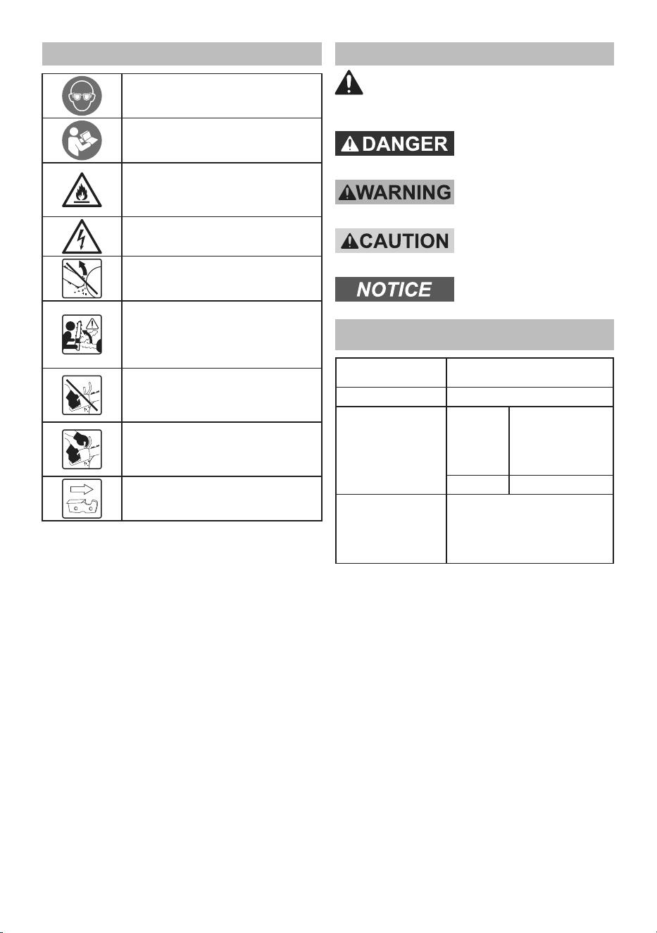
Symbology
WARNING marking concerning Risk
of Eye Injury. Wear ANSI-approved
safety goggles with side shields.
Read the manual before
set-up and/or use.
WARNING marking
concerning Risk of Fire.
Do not cover Charger ventilation ducts.
Keep flammable objects away.
WARNING marking concerning
Risk of Electric Shock.
WARNING marking concerning Risk
of Kickback. Contact of the guide bar
tip with any object should be avoided.
WARNING marking concerning
Risk of Kickback. Tip contact
can cause the guide bar to move
suddenly upward and backward,
which can cause serious injury.
WARNING marking concerning
Risk of Loss of Control.
Do not operate the chain
saw with only one hand.
WARNING marking concerning
Risk of Loss of Control.
Always use two hands when
operating the chain saw.
WARNING marking concerning
Saw Chain Orientation. Cutters
must face in direction of rotation.
Warning Symbols and Definitions
This is the safety alert symbol. It is used to
alert you to potential personal injury hazards.
Obey all safety messages that follow this symbol to
avoid possible injury or death.
Indicates a hazardous
situation which, if not
avoided, will result in death or serious injury.
Indicates a hazardous
situation which, if not
avoided, could result in death or serious injury.
Indicates a hazardous
situation which, if not
avoided, could result in minor or moderate injury.
Addresses practices not
related to personal injury.
SPECIFICATIONS
Application
Fits both conventional and
worm drive 7-1/4" circular saws
Max Cut Depth
@
90° 12 inches
Lubrication
Type
Bar and chain oil
(sold separately - if
not available,
SAE 30W motor
oil may be used)
Capacity 0.68 fl. oz. (20 ml)
Cutting Attachment
Low Profile Anti-Kickback Chain
Length: 33.28"
Pitch: 3/8"
Gauge: 0.043"
# of teeth: 23 w / 46 Drive Links

Page 6 For technical questions, please call 1-888-866-5797. Item 58804
SETUP–BEFORE USE
Read the ENTIRE IMPORTANT SAFETY INFORMATION section at the beginning of this manual
including all text under subheadings therein before set up or use of this product.
Read the manual for the circular saw the Beam Cutter will be installed on before setup or use.
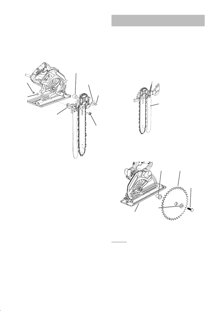
Functional Description
Guide Bar
Saw
Chain
Hinge
Chain
Guide Bar
Bolt
Bearing
Housing
Hinge
Brackets
Splitter
Tension
Screw
Back
Plate
Clutch
Drum
Bearing
Housing
Oil
Reservoir
Page 7For technical questions, please call 1-888-866-5797.Item 58804
OPERATION
Read the ENTIRE IMPORTANT SAFETY INFORMATION section at the beginning of this
manual including all text under subheadings therein before set up or use of this product.
Tool Set Up
TO PREVENT SERIOUS INJURY FROM ACCIDENTAL OPERATION:
Make sure that the circular saw Trigger is in the off-position and unplug the tool from its electrical
outlet
and/or make sure the Battery Pack is removed
before performing any procedure in this section.
IMPORTANT: Read the operation manual for the circular saw the Beam Cutter
will be mounted on before installing and operating the Cutter.
Note: Some brands/models of circular saws may require removal of the
lower blade guard to allow installation of the Beam Cutter.
Note: During assembly of the Splitter to the Saw, make sure the Splitter
is parallel with the Guide Bar for optimal results.
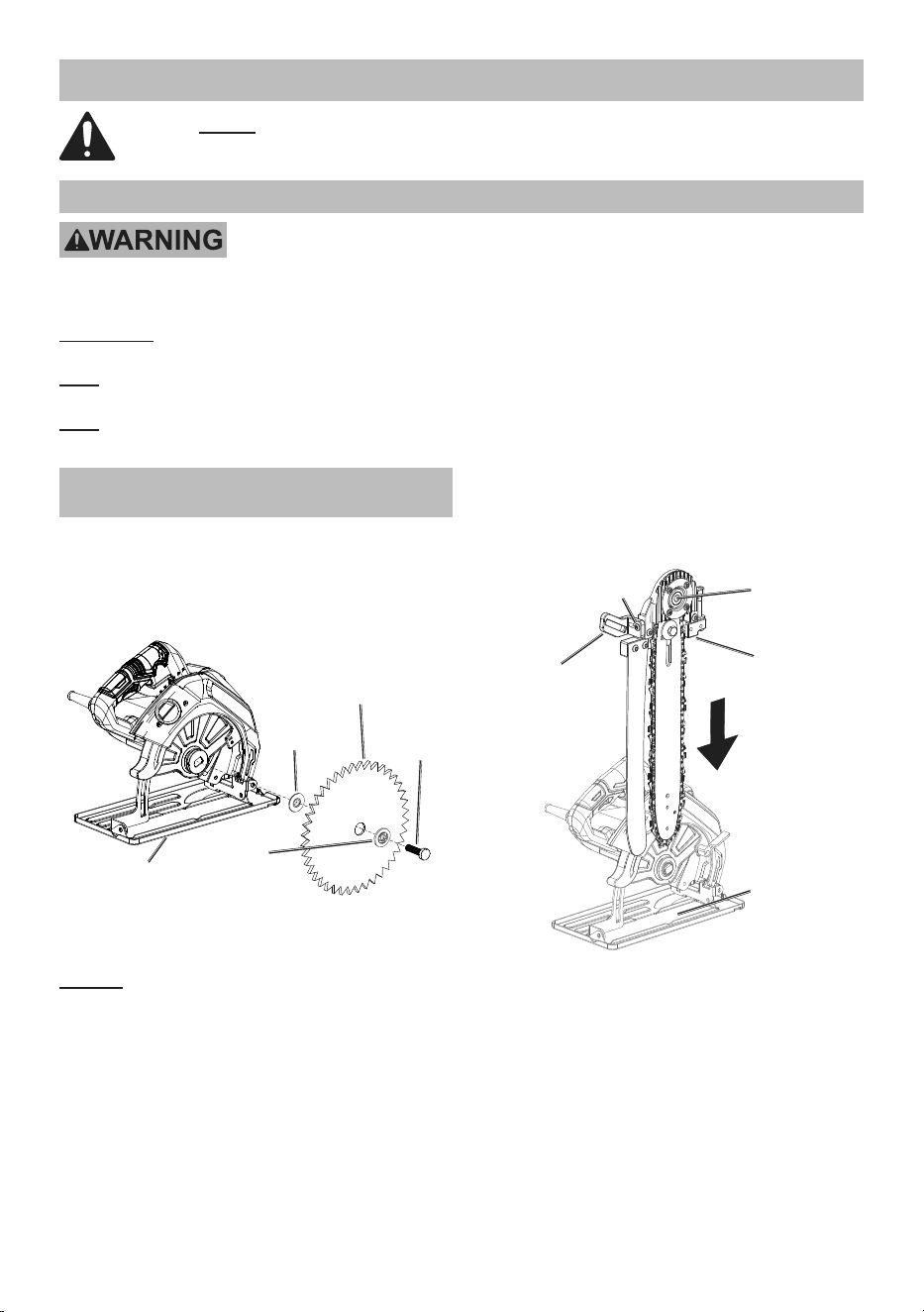
Installing on Conventional Circular
Saw (Right Side Blade)
1. Move the base plate on the circular saw
to the fully extended position.
2. Hold in the spindle lock on the circular
saw while removing the arbor bolt, outer
flange, saw blade, and inner flange.
Base Plate
Fully Extended
Arbor
Bolt
Inner
Flange
Outer
Flange
Saw
Blade
3. From the supplied hardware, determine the correct
size Arbor Bolt (35, 36, 37, 38, or 39) and Outer
Flange (32 or 33) to fit the circular saw being used.
NOTICE: Be sure to use an Outer Flange with
the Arbor Bolt when installing the Beam Cutter.
Failure to do so may result in incorrect operation
and damage to the Bearing Housing.
4. Attach the Mounting Bracket to the Beam
Cutter Assembly using a M6 x 20 Screw (25).
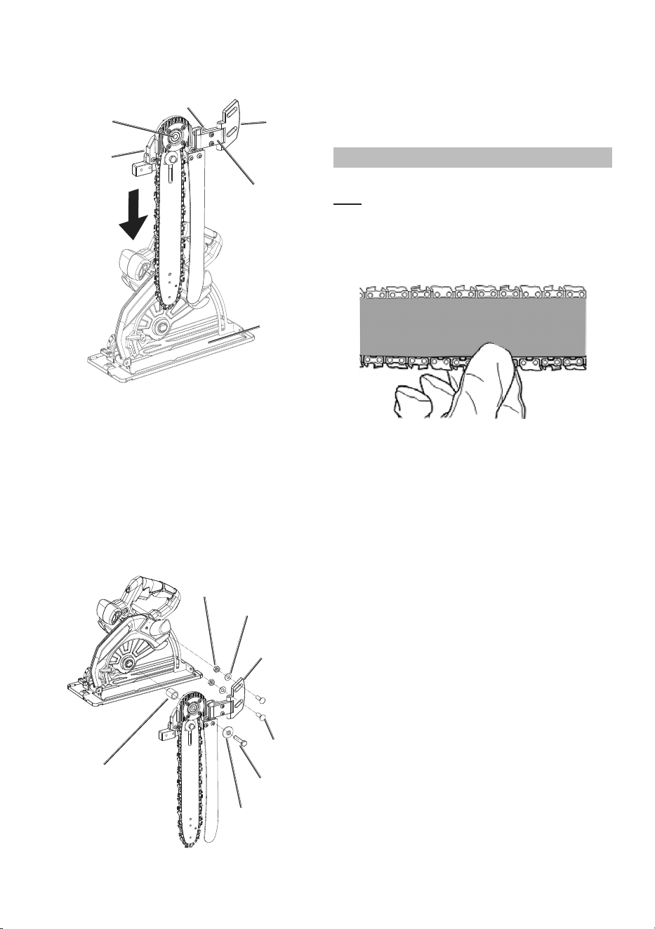
5. Slide the Beam Cutter Assembly down through the
blade opening in the base plate of the circular saw.
M6 x 20
Screw (25)
Beam
Cutter
Assembly
Mounting
Bracket
Opening
in Base
Plate
Mounting
Hole
Page 8 For technical questions, please call 1-888-866-5797. Item 58804
6. Place the Inner Bushing (34) over the saw
spindle and align the center mounting hole
of the Beam Cutter with the saw spindle.
7. Insert the correct size Arbor Bolt and Outer
Flange through the mounting hole and thread
into the saw spindle. Finger tighten.
8. Insert an M6 x 25 Screw (6) with T-Nut (28)
through the Mounting Bracket slot on the Beam
Cutter and the slide on the saw. Secure with
M6 Nut (26) and Washer (27). Finger tighten.
Arbor
Bolt
Inner
Bushing (34)
Outer
Flange
M6 x 25
Screw (6)
with
T-Nut (28)
M6 Nut
(26)
Washer
(27)
Mounting
Bracket
9. Align the Beam Cutter Assembly at a
90° angle to the saw’s base plate.
10. Hold in the spindle lock on the circular saw and
wrench tighten the Arbor Bolt — do not over tighten.
11. Wrench tighten the M6 Nut to secure the
Beam Cutter Assembly to the circular saw.
Installing on Worm Drive Circular
Saw (Left Side Blade)
1. Changing the Splitter orientation:
a. Remove M6x12 Screws (17),
then remove the Splitter.
b. Flip the Splitter over so that the inner curved
side is facing the Guide Bar, then align
Splitter with holes on the right side.
c. Replace Screws (17) and finger tighten.
d. Adjust the Splitter to be parallel to the Guide
Bar, then tighten the Screws (17) securely.
M6 x 12 Screws (17)
Splitter (Left
Side Blade
Configuration)
2. Move the base plate on the circular saw
to the fully extended position.
3. Hold in the spindle lock on the circular saw
while removing the arbor bolt, outer flange,
saw blade, and inner flange or bushing.
Base Plate
Fully Extended
Arbor
Bolt
Saw
Blade
Outer
Flange
Inner
Bushing
4. From the supplied hardware, determine the correct
size Arbor Bolt (35, 36, 37, 38, or 39) and Outer
Flange (32 or 33) to fit the circular saw being used.
NOTICE: Be sure to use an Outer Flange with
the Arbor Bolt when installing the Beam Cutter.
Failure to do so may result in incorrect operation
and damage to the Bearing Housing.
Page 9For technical questions, please call 1-888-866-5797.Item 58804
5. Attach the Hinge (10) to the Beam Cutter
Assembly using two Hinge Brackets (15, 16)
and two M6 x 12 Screws (17). Do not
fully tighten the Screws at this time.
M6 x 12 Screws (17)
Hinge
(10)
Opening
in Base
Plate
Hinge Brackets
(15, 16)
Mounting
Hole
Beam
Cutter
Assembly
6. Slide the Beam Cutter Assembly down through the
blade opening in the base plate of the circular saw.
7. Place the Inner Bushing (34) over the saw
spindle and align the center mounting hole
of the Beam Cutter with the saw spindle.
8. Insert the correct size Arbor Bolt and Outer
Flange through the mounting hole and thread
into the saw spindle. Finger tighten.
9. Insert two M8 x 25 Bolts (11) through the
Hinge slots on the Beam Cutter and the slide
on the saw. Secure with two M8 Nuts (13)
and Washers (12). Finger tighten.
Arbor
Bolt
Inner
Bushing (34)
Outer Outer
FlangeFlange
M8 x 25
Bolt (11)
M8 Nut (13)
Washer (12)
Hinge
10. Align the Beam Cutter Assembly at a
90° angle to the saw’s base plate.
11. Hold in the spindle lock on the circular saw
and wrench tighten the Arbor Bolt — do not
over tighten. Wrench tighten the M8 Nuts and
the M6 x 12 Screws from step 4 to secure the
Beam Cutter Assembly to the circular saw.
Checking Saw Chain Tension
1. Before using, check the Saw Chain tension.
Note: New Saw Chains often need to be tensioned
several times during first use. Check a new
Saw Chain’s tension often when first using.
2. While wearing heavy-duty gloves, use your index
finger and thumb to carefully grab the Saw Chain
in the middle section under the Guide Bar.
3. Pull the Saw Chain away from the Guide Bar.
4. The Saw Chain should snap back against the
Chain Guide Bar. The Chain should fit snugly in the
groove of the Guide Bar, yet you should still be able
to slide the chain along the Guide Bar by hand.
5. There should be no sagging between the Guide Bar
and Saw Chain on the underside of the Guide Bar.
Page 10 For technical questions, please call 1-888-866-5797. Item 58804
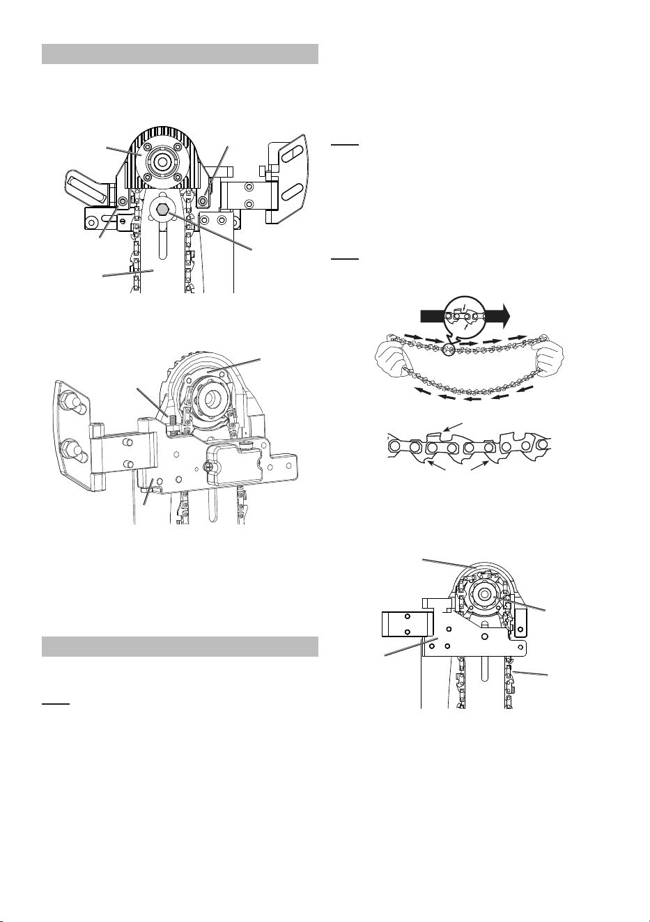
Adjusting Saw Chain Tension
1. Remove the Beam Cutter from the circular saw.
2. For fine adjustment up to 1/8", loosen the two
M6 x 25 Hex Screws on the Bearing Housing.
Guide Bar
Chain
Guide Bar
Bolt
Bearing
Housing
M6 x 25
Hex Screw
M6 x 25
Hex Screw
3. Turn the Tension Screw clockwise to increase
chain tension and counterclockwise to decrease
tension. Tighten the M6 x 25 Hex Screws.
Tension
Screw
Back PlateBack Plate
Bearing
Housing
4. If increased tension is needed, loosen the Guide
Bar Bolt and slide the Guide Bar down to tighten
the Chain. Tighten the Guide Bar Bolt.
5. Check the Saw Chain tension again following
steps 2 through 5 under Checking Saw Chain
Tension. If needed, repeat the adjusting
steps to achieve the correct tension.
Replacing the Saw Chain
1. Soak the new Saw Chain overnight in
Bar and Chain Oil (sold separately).
Note: Wear heavy-duty gloves when
working with Saw Chains.
2. Remove the Beam Cutter from the circular saw.
3. Remove the Guide Bar Bolt and Washer.
4. Remove the two M6 x 25 Hex Screws on
the Bearing Housing and separate the
Bearing Housing from the Back Plate.
5. Remove the Guide Bar and old saw
chain from the Beam Cutter.
Note: Check the condition of the Sprocket when
replacing the chain. The Sprocket should be
replaced if it shows signs of wear or is damaged.
If needed, have the Sprocket replaced and the
bearings greased by a qualified technician.
6. Flip the Guide Bar over before mounting
the new Saw Chain. This will ensure that
the Guide Bar wears evenly over time.
Note: Check the condition of the Guide
Bar when replacing the chain. Refer to
Guide Bar Care on page 13.
Cutters must face in
direction of rotation
Tip of
Bar
Cutter
Drivelink
Cutter
Drive Links
7. Place the new Saw Chain behind the Clutch
Drum, around the Sprocket and onto the Sprocket
teeth. Make sure the Cutters of the Saw
Chain are facing in the direction of rotation.
Back
Plate
Clutch
Drum
Saw
Chain
Bearing
Housing
8. Reattach the Bearing Housing to the Back
Plate by replacing the two Hex Screws.
Page 11For technical questions, please call 1-888-866-5797.Item 58804
9. Reattach the Guide Bar with the Guide Bar
Bolt and Flange. Finger tighten the Bolt.
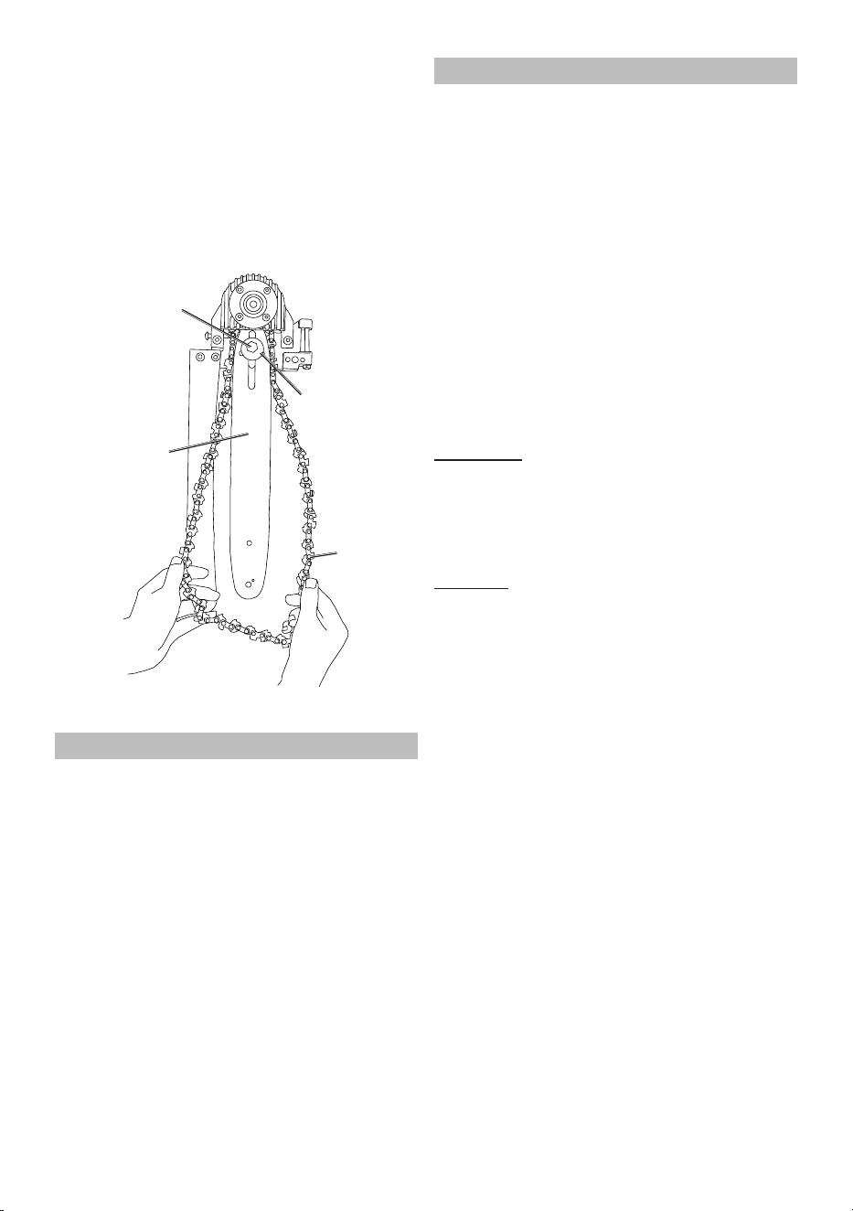
10. Place the Saw Chain over the Guide Bar. Fit the
Drive Links into the groove around the Guide Bar.
11. Pull the Guide Bar forward to take up slack in the
Chain. Check again that the Saw Chain cutters are
aligned properly and the Saw Chain Drive Links
are seated completely in the slot of the Guide Bar.
12. Move the Chain back and forth to make sure it is in
properly seated on the Sprocket. Wrench tighten
the Guide Bar Bolt to secure the Guide Bar.
Guide Bar
Saw
Chain
Guide Bar Bolt
Flange
13. Tension the Saw Chain following the steps in
Adjusting Saw Chain Tension on page 10.
Workpiece and Work Area Set Up
1. Designate a work area that is clean and well lit.
The work area must not allow access by children
or pets to prevent distraction and injury.
2. If using a corded circular saw and extension
cord, route the extension cord along a safe
route to reach the work area without creating
a tripping hazard or exposing the extension
cord to possible damage. The extension cord
must reach the work area with enough extra
length to allow free movement while working.
3. Secure loose workpieces using a vise or clamps
(not included) to prevent movement while working.
4. There must not be objects, such as utility lines,
nearby that will present a hazard while working.
General Operations
1. Before first use and before each use thereafter,
remove the Oil Reservoir Cover. Inspect the Cover
for damage. Fill the Oil Reservoir to just below
top with oil (not included). Refer to Specifications
Chart on page 5 for oil type. Then replace
the Oil Reservoir Cover. Oil is automatically
applied to the Saw Chain during operation.
2. Make sure that the circular saw Trigger is
in the off-position, then connect an outdoor
rated extension cord (not included) to the saw
power cord. Make sure the electrical cord is
away from the cutting area. If using a cordless
circular saw, insert the battery pack.
3. Grasp the circular saw handles with both
hands. Always grip the handle with the
thumb and fingers encircling the handle.
4. Grip saw firmly with both hands, rest the
front of the base plate on workpiece with
the Saw Chain behind the work.
IMPORTANT: Do not start the saw if the
Saw Chain is in contact with anything.
5. Press the circular saw Trigger to start the tool.
6. Allow the saw to come up to full speed
before touching the workpiece.
7. Guide the Saw Chain into the workpiece.
WARNING! TO PREVENT SERIOUS INJURY:
Keep the saw’s base plate pressed firmly against
the workpiece while cutting to prevent kickback.
8. Maintain a smooth motion, guiding the Saw Chain
through the material as it is cut. Follow the cut.
Do not press too hard. If the saw slows down as
it is cutting, apply less pressure on the saw.
9. To stop the saw, release the Trigger.
10. Allow the saw to come to a complete
stop before setting it down.

Page 12 For technical questions, please call 1-888-866-5797. Item 58804
MAINTENANCE AND SERVICING
Procedures not specifically explained in this manual must
be performed only by a qualified technician.
TO PREVENT SERIOUS INJURY FROM ACCIDENTAL OPERATION:
Make sure that the circular saw Trigger is in the off-position and unplug the tool from its electrical outlet
and/or make sure the Battery Pack is removed before performing any procedure in this section.
TO PREVENT SERIOUS INJURY FROM TOOL FAILURE:
Do not use damaged equipment. If abnormal noise or vibration
occurs, have the problem corrected before further use.
Cleaning, Maintenance,
and Lubrication
1. BEFORE EACH USE, inspect the general
condition of the tool. Check for:
• loose hardware
• misalignment or binding of moving parts
• cracked or broken parts
• dull or damaged Saw Chain
• any other condition that may
affect its safe operation.
2. BEFORE FIRST USE AND BEFORE EACH USE
THEREAFTER, make sure the Oil Reservoir
is filled with oil (not included). Refer to
Specifications Chart on page 5 for oil type.
3. IF THE SAW CHAIN BECOMES LOOSE,
adjust the Saw Chain tension as described under
Adjusting Saw Chain Tension on page 10.
4. PERIODICALLY OR WHEN REPLACING SAW
CHAIN, turn the Chain Guide Bar over to distribute
the wear on it. Replace the Chain Guide Bar when
bent, cracked, or when the Saw Chain moves
excessively from side to side on the Guide Bar due
to wear. Refer to Guide Bar Care on page 13.
WARNING! TO PREVENT SERIOUS INJURY:
Replace the Saw Chain and Chain Guide Bar only
with an identical Saw Chain and Guide Bar.
5. AFTER USE, wipe external surfaces of the tool with
a clean, dry cloth. If necessary use a mild detergent.
Do not use solvents. Do not immerse this tool in
liquid. Store the tool indoors out of children’s reach.
Sharpening/Replacing the Saw Chain
CAUTION! Wear heavy-duty work gloves
when handling the Saw Chain.
1. For smooth and safe operation,
always keep the Saw Chain cutters sharp.
2. Have the cutters sharpened by a qualified technician
when you notice any of the following symptoms:
a. The sawdust becomes powder-like.
b. You can’t make the cut without extra force.
c. The saw does not cut straight.
d. Vibration increases.
3. A Saw Chain that is damaged or too worn
to be restored to a usable condition by
sharpening will need to be replaced. Refer to
Replacing the Saw Chain on page 10.
WARNING! TO PREVENT SERIOUS INJURY: Replace
the Saw Chain only with an identical Saw Chain.
Page 13For technical questions, please call 1-888-866-5797.Item 58804
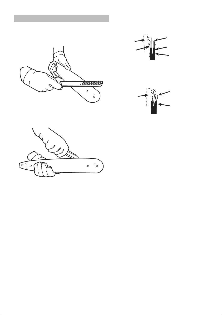
Guide Bar Care
1. Remove the Guide Bar periodically
to clean and lubricate.
2. Deburr rails of Guide Bar as needed.
Use a flat file to make side edges square.
Deburring Guide Bar
3. Remove sawdust and sap from the Bar Groove using
a Guide Bar cleaning tool (sold separately), then
lubricate the nose sprocket at the ports with grease.
Cleaning and Lubricating Guide Bar
4. Reverse the Guide Bar when replacing the
Saw Chain to prevent uneven wear.
5. The rails of the Guide Bar groove should
always be parallel to each other. Place a
ruler along the surface of the Guide Bar and
Saw Chain. If there is a gap, the bar is normal.
Straight
Guide Bar
Ruler
Rail
Saw
Chain
Gap
Normal Guide Bar
If the ruler is flush with the Guide Bar and
Saw Chain, or the Chain tilts to one side, then
the Bar is worn and needs to be replaced.
Ruler
Worn Guide
Bar
Tilting Saw
Chain
Worn Guide Bar

Page 14 For technical questions, please call 1-888-866-5797. Item 58804
PLEASE READ THE FOLLOWING CAREFULLY
THE MANUFACTURER AND/OR DISTRIBUTOR HAS PROVIDED THE PARTS LIST AND ASSEMBLY DIAGRAM
IN THIS MANUAL AS A REFERENCE TOOL ONLY. NEITHER THE MANUFACTURER OR DISTRIBUTOR
MAKES ANY REPRESENTATION OR WARRANTY OF ANY KIND TO THE BUYER THAT HE OR SHE IS
QUALIFIED TO MAKE ANY REPAIRS TO THE PRODUCT, OR THAT HE OR SHE IS QUALIFIED TO REPLACE
ANY PARTS OF THE PRODUCT. IN FACT, THE MANUFACTURER AND/OR DISTRIBUTOR EXPRESSLY
STATES THAT ALL REPAIRS AND PARTS REPLACEMENTS SHOULD BE UNDERTAKEN BY CERTIFIED AND
LICENSED TECHNICIANS, AND NOT BY THE BUYER. THE BUYER ASSUMES ALL RISK AND LIABILITY
ARISING OUT OF HIS OR HER REPAIRS TO THE ORIGINAL PRODUCT OR REPLACEMENT PARTS
THERETO, OR ARISING OUT OF HIS OR HER INSTALLATION OF REPLACEMENT PARTS THERETO.
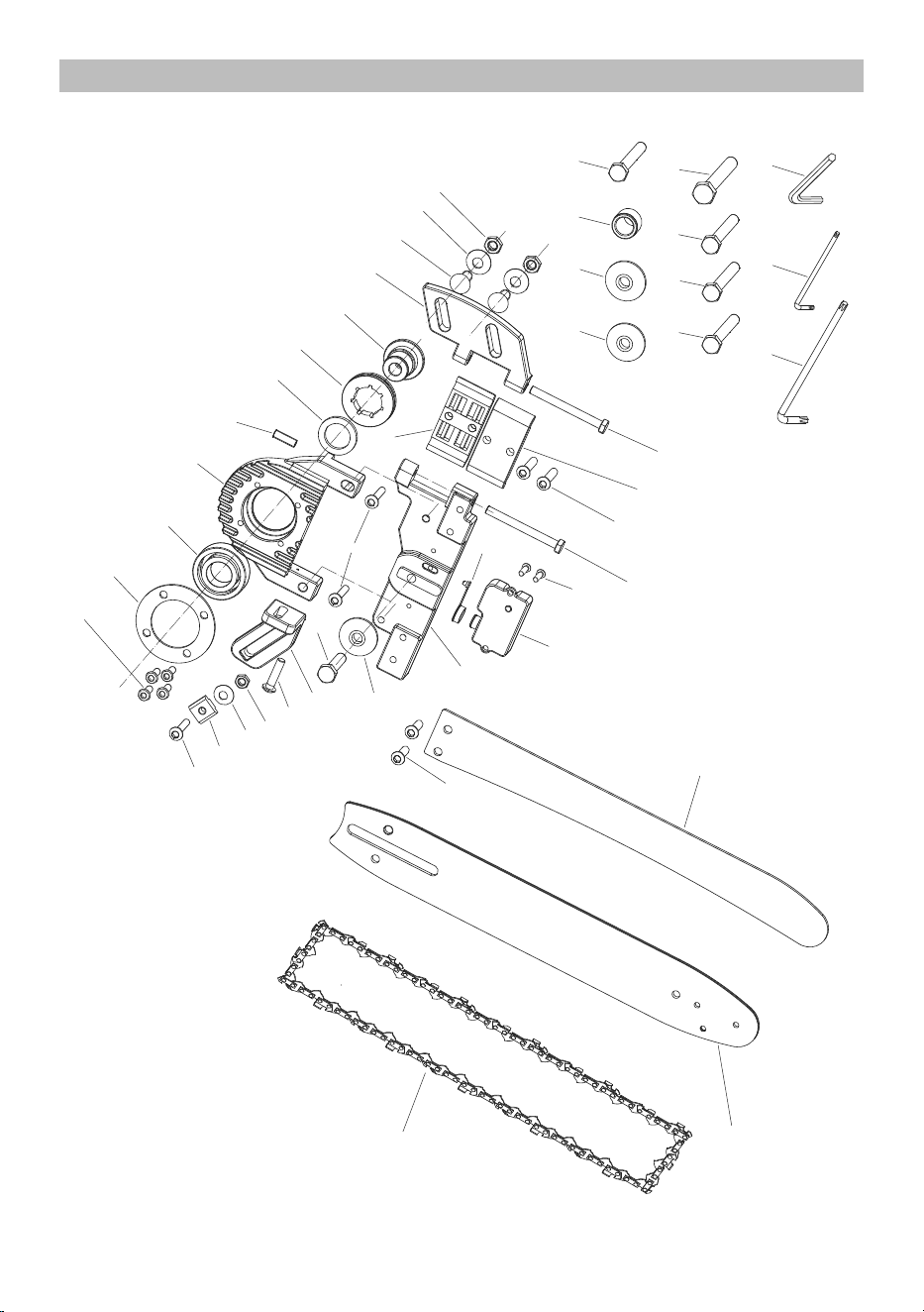
PARTS LIST AND DIAGRAM
Parts List
Part Description Qty
1 Screw M5 x 12 4
2
Bearing Pressure Plate
1
3
Bearing 6004
1
4
Bearing Housing
1
5
Hex Screw M6 x 12
1
6
Hex Screw M6 x 25
3
7
Washer
1
8
Chain Wheel
1
9
Axle Sleeve
1
10
Hinge
1
11
Bolt M8x25
2
12
Washer
2
13
Nut M8
2
14
Bolt M6 x 60
2
15
Hinge Bracket I
1
16
Hinge Bracket II
1
17
Hex Screw M6 x 12
4
18
Hex Screw M4 x 12
2
19
Oil Reservoir
1
20
Oil Reservoir Cover
1
21 Back Plate 1
Part Description Qty
22
Guide Bar Bolt Flange
1
23
Guide Bar Bolt M8 x 25
1
24
Mounting Bracket
1
25
Hex Screw M6 x 20
1
26
Nut M6
1
27
Washer
1
28
T-Nut
1
29
Splitter
1
30
Guide Bar
1
31
Saw Chain
1
32
Outer Flange Ø8
1
33
Outer Flange Ø10
1
34
Inner Bushing
1
35
Arbor Bolt M8 x 40
1
36
Arbor Bolt 5/16"-24 x 40
1
37
Arbor Bolt 5/16"-18 x 40
1
38
Arbor Bolt M8 x 40 Left
1
39
Arbor Bolt 3/8"-24 x 40 Left
1
40
Wrench T25
1
41 Wrench T27
1
42 Hex Key 1
Record Product’s Serial Number Here:
Note: If product has no serial number, record month and year of purchase instead.
Note: Some parts are listed and shown for illustration purposes only, and are not available
individually as replacement parts. Specify UPC 193175446848 when ordering parts.
Page 15For technical questions, please call 1-888-866-5797.Item 58804
Assembly Diagram
1
2
3
4
5
7
8
9
1 0
1 1
1 2
1 3
1 4
1 5
1 6
1 7
1 8
1 9
2 0
6
2 2
2 8
2 7
2 4
2 6
2 5
3 1
3 2
3 3
3 4 3 5
3 6
3 7 3 8
3 9
4 0
4 1
2 3
6
2 9
1 7
3 0
4 2
2 1
1 4

LIMITED 90 DAY WARRANTY
Harbor Freight Tools Co. makes every effort to assure that its products meet high quality and durability
standards, and warrants to the original purchaser that this product is free from defects in materials
and workmanship for the period of 90 days from the date of purchase. This warranty does not apply to
damage due directly or indirectly, to misuse, abuse, negligence or accidents, repairs or alterations outside
our facilities, criminal activity, improper installation, normal wear and tear, or to lack of maintenance.
We shall in no event be liable for death, injuries to persons or property, or for incidental, contingent,
special or consequential damages arising from the use of our product. Some states do not allow the
exclusion or limitation of incidental or consequential damages, so the above limitation of exclusion
may not apply to you. THIS WARRANTY IS EXPRESSLY IN LIEU OF ALL OTHER WARRANTIES,
EXPRESS OR IMPLIED, INCLUDING THE WARRANTIES OF MERCHANTABILITY AND FITNESS.
To take advantage of this warranty, the product or part must be returned to us with transportation charges
prepaid. Proof of purchase date and an explanation of the complaint must accompany the merchandise.
If our inspection verifies the defect, we will either repair or replace the product at our election or we may
elect to refund the purchase price if we cannot readily and quickly provide you with a replacement. We will
return repaired products at our expense, but if we determine there is no defect, or that the defect resulted
from causes not within the scope of our warranty, then you must bear the cost of returning the product.
This warranty gives you specific legal rights and you may also have other rights which vary from state to state.
26677 Agoura Road • Calabasas, CA 91302 • 1-888-866-5797
Visit our website at: http://www.harborfreight.com
Email our technical support at: [email protected]
For technical questions, please call 1-888-866-5797
Copyright
©
2022 by Harbor Freight Tools
®
. All rights reserved. No portion of this manual or
any artwork contained herein may be reproduced in any shape or form without the express
written consent of Harbor Freight Tools. Diagrams within this manual may not be drawn
proportionally. Due to continuing improvements, actual product may differ slightly from the
product described herein. Tools required for assembly and service may not be included.
