Owner’s Manual & Safety Instructions
Save This Manual Keep this manual for the safety warnings and precautions, assembly,
operating, inspection, maintenance and cleaning procedures. Write the product’s serial number in the
back of the manual (or month and year of purchase if product has no number). Keep this manual and the
receipt in a safe and dry place for future reference. 24k
When unpacking, make sure that the product is intact
and undamaged. If any parts are missing or broken,
please call 1-800-444-3353 as soon as possible.
Copyright
©
2022 by Harbor Freight Tools
®
. All rights reserved.
No portion of this manual or any artwork contained herein may be reproduced in
any shape or form without the express written consent of Harbor Freight Tools.
Diagrams within this manual may not be drawn proportionally. Due to continuing
improvements, actual product may differ slightly from the product described herein.
Tools required for assembly and service may not be included.
read this material before using this product.
Failure to do so can result in serious injury.
SaVe THiS ManuaL.
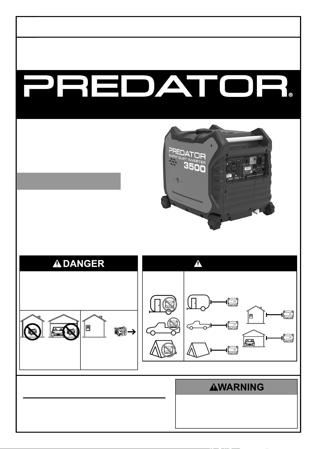
3500 WATT
PORTABLE
INVERTER
GENERATOR
3000 RUNNING WATTS
3500 MAX STARTING WATTS
Visit our website at: https://www.harborfreight.com
email our technical support at: [email protected]
email our engine support at: [email protected]
71358
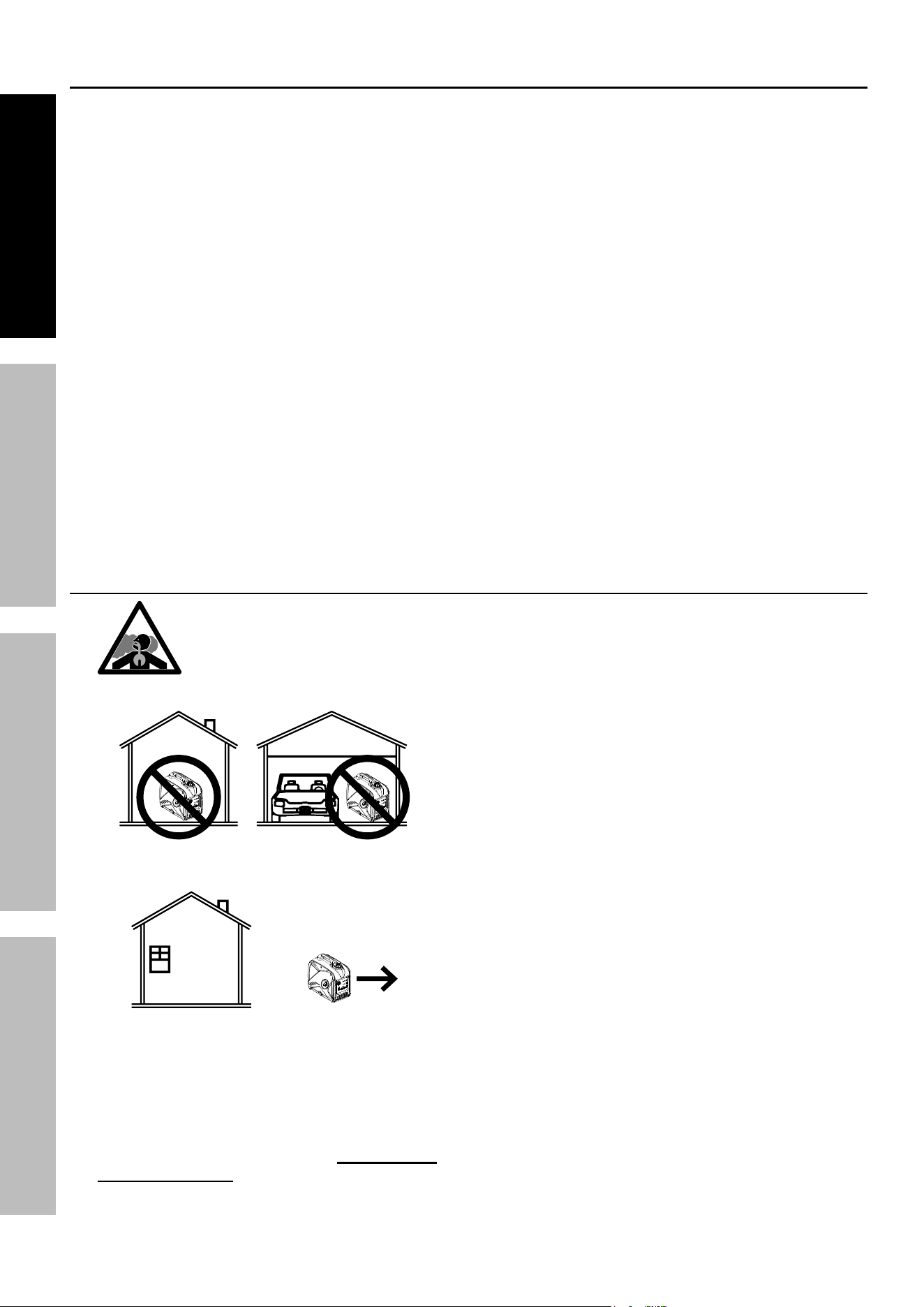
DanGer
using a generator indoors Can
KiLL yOu in MinuTeS.
Generator exhaust contains
carbon monoxide. This is a poison
you cannot see or smell.
Do not use in
trailers, truck
beds, or tents.
use at least 20 feet away from
people, animals, and structures
with exhaust pointed away.
20′
20′
20′
20′
20′
neVer use inside
a home or garage,
eVen iF doors and
windows are open.
Only use OuTSiDe
and far away from
windows, doors,
and vents.
SUPER QUIET INVERTER

Page 2
For technical questions, please call 1-800-444-3353.
ITEM 71358
Table of Contents
Specifications ............................................................... 2
Safety ...........................................................................3
Setup ............................................................................8
Operation .....................................................................12
Maintenance ................................................................ 18
Troubleshooting ........................................................... 23
Parts List and Diagram ................................................ 26
Warranties ................................................................... 29
Specifications
Generator
Output
120 VAC, 60 Hz, 25 A, 1 Phase
12 VDC, 8 A (nominal)
3000 Running Watts
3500 Maximum Starting Watts
Receptacles
2 x NEMA #5-20 (3-prong, 120 VAC)
1 x NEMA #L5-30 (3-prong, 120 VAC)
1 x 12 VDC Two Pin Outlet
Displacement 212 cc
Compression Ratio 9.0:1
Engine Type
Horizontal Single Cylinder
4-stroke, OHV
Cooling System Forced air cooled
Fuel
Type
87+ octane, stabilizer-treated
unleaded gasoline
Capacity 2.33 Gallon / 8.80 Liter
Engine Oil
Type SAE 10W-30
Capacity 20 fl. oz.
Run Time @ 25% Load
with full tank
11 hr.
Sound Level at 23 feet, 25% load 56 dB(A)
Bore x Stroke 70 mm x 55 mm
Spark Plug
Type F6RTC (Torch) or equivalent
Gap 0.027"– 0.031"
Valve Clearance
Intake 0.002"– 0.003"
Exhaust 0.002"– 0.003"
Engine Speed 2600 – 3600 RPM
The emissions control system for this Engine is warranted for standards set by the
U.S. Environmental Protection Agency and by the California Air Resources Board (also known as CARB).
For warranty information, refer to the last pages of this manual.
Page 3
For technical questions, please call 1-800-444-3353.
ITEM 71358
SaFeTyOperaTiOnMainTenanCe SeTup
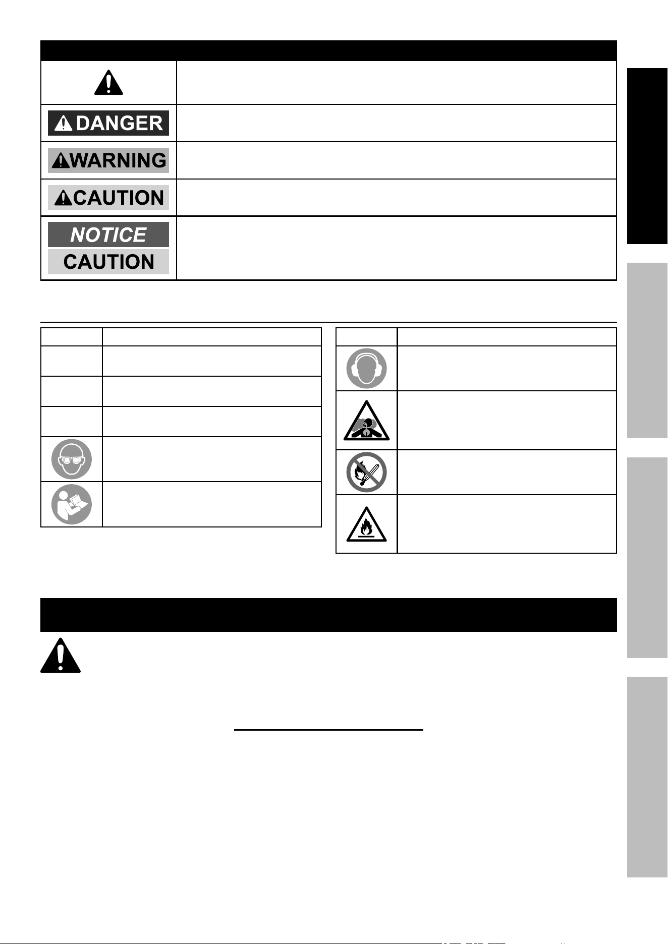
WarninG SyMBOLS anD DeFiniTiOnS
This is the safety alert symbol. It is used to alert you to potential
personal injury hazards. Obey all safety messages that
follow this symbol to avoid possible injury or death.
Indicates a hazardous situation which, if not avoided,
will result in death or serious injury.
Indicates a hazardous situation which, if not avoided,
could result in death or serious injury.
Indicates a hazardous situation which, if not avoided,
could result in minor or moderate injury.
Addresses practices not related to personal injury.
Symbol Definitions
Symbol property or Statement
rpM
Revolutions Per Minute
Hp
Horsepower
aWG
American Wire Gauge
WARNING marking concerning
Risk of Eye Injury. Wear ANSI-approved
safety goggles with side shields.
Read the manual before
set-up and/or use.
Symbol property or Statement
WARNING marking concerning
Risk of Hearing Loss.
Wear hearing protection.
WARNING marking concerning
Risk of Respiratory Injury.
Operate engine OUTSIDE and far away
from windows, doors, and vents.
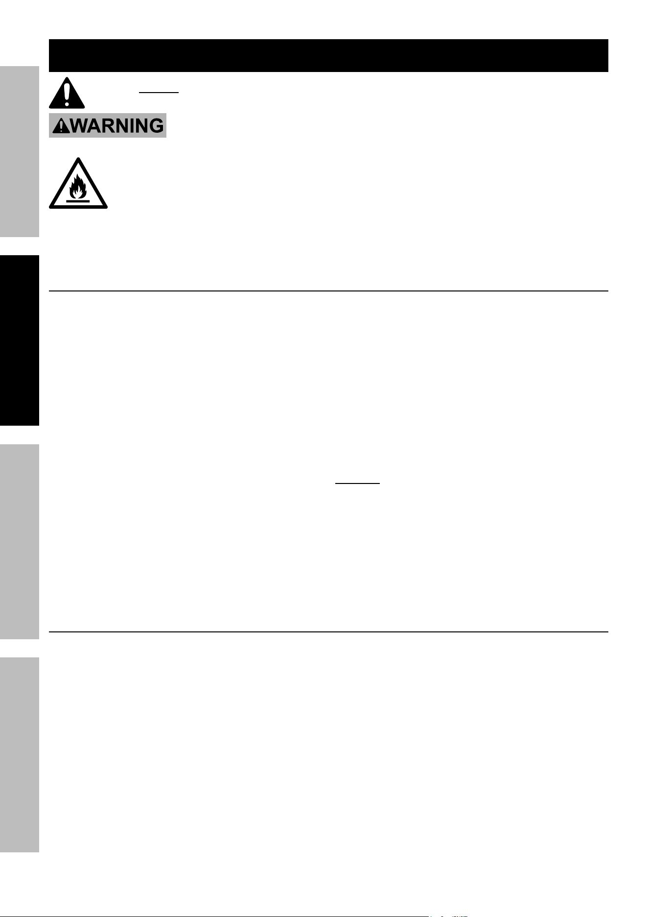
WARNING marking concerning
Risk of Fire while handling fuel.
Do not smoke while handling fuel.
WARNING marking concerning
Risk of Fire. Do not refuel while
operating. Keep flammable
objects away from engine.
iMpOrTanT SaFeTy inSTruCTiOnS
WarninG! read all instructions.
Failure to follow all instructions listed below may result in fire, serious injury and/or DeaTH.
The warnings and precautions discussed in this manual cannot cover all possible conditions and
situations that may occur. It must be understood by the operator that common sense and caution
are factors which cannot be built into this product, but must be supplied by the operator.
SaVe THeSe inSTruCTiOnS
Page 4
For technical questions, please call 1-800-444-3353.
ITEM 71358
SaFeTy OperaTiOn MainTenanCeSeTup
Setup precautions
1. Gasoline fuel and fumes are flammable, and
potentially explosive. Use proper fuel storage
and handling procedures. Do not store fuel
or other flammable materials nearby.
2. Have multiple ABC class fire extinguishers nearby.
3. Operation of this equipment may create sparks that
can start fires around dry vegetation.
A spark arrestor may be required. The operator
should contact local fire agencies for laws or
regulations relating to fire prevention requirements.
4. Set up and use only on a flat, level,
well-ventilated surface.
5. All connections and conduits from the Generator
to the load must only be installed by trained and
licensed electricians, and in compliance with all
relevant local, state, and federal electrical codes and
standards, and other regulations where applicable.
6. Connections for standby power to a building
electrical system must be made by a qualified
electrician. The connection must isolate the
Generator power from utility power, and must
comply with all applicable laws and electrical codes.
7. A transfer switch should be installed by a
licensed electrician in compliance with all
applicable laws and electrical codes.
8. Wear ANSI-approved safety goggles, heavy-duty
work gloves, and dust mask/respirator during set up.
9. Use only lubricants and fuel recommended
in the Specifications chart of this manual.
10. Improper connections to a building electrical system
can allow electrical current from the Generator
to backfeed into the utility lines. Such backfeed
may electrocute utility company workers or others
who contact the lines during a power outage,
and the Generator may explode, burn, or cause
fires when utility power is restored. Consult
the utility company and a qualified electrician if
intending to use the Generator for back up power.
11. Do not operate the Generator before grounding.
The Generator must be earth-grounded
in accordance with all relevant electrical
codes and standards before operation.
12. Install carbon monoxide alarm(s) with
battery backup in nearby buildings according
to manufacturer’s instructions.
Operating precautions
1. CarBOn MOnOXiDe HaZarD
using a generator indoors Can KiLL
yOu in MinuTeS.
Generator exhaust contains
carbon monoxide. This is a poison
you cannot see or smell.
OFF
RUN
START
LOW OIL
OVERLOAD
OUTPUT
PARALLEL OUTLETS
RESET
AC 120V
RESET
DC 12V
ESC
THROTTLE
OFF
RUN
START
LOW OIL
OVERLOAD
OUTPUT
PARALLEL OUTLETS
RESET
AC 120V
RESET
DC 12V
ESC
THROTTLE
NEVER use inside a home or garage,
EVEN IF doors and windows are open.
OFF
RUN
START
LOW OIL
OVERLOAD
OUTPUT
PARALLEL OUTLETS
RESET
AC 120V
RESET
DC 12V
ESC
THROTTLE
Only use OUTSIDE and far away from windows,
doors, and vents.
2. CarBOn MOnOXiDe SHuTOFF
DanGer! TO preVenT SeriOuS
inJury anD DeaTH FrOM
CarBOn MOnOXiDe inHaLaTiOn:
The Carbon Monoxide sensor is an additional
layer of protection only. Do not use the
Generator in any area or situation that will
allow carbon monoxide to accumulate.
• FLASHING RED LIGHT:
Dangerous levels of carbon monoxide gas have
built up and generator will shutoff.
Leave immediately until area has aired
out. Move Generator to well-ventilated
area before operation.
• FLASHING YELLOW LIGHT:
Carbon monoxide sensor malfunction.
Sensor needs service. Do not use the
Generator until the sensor is working
properly. For technical questions,
please call 1-800-444-3353.
NOTE: Yellow light flashes once after
starting to indicate passing self-check
and is functioning normally.
Carbon Monoxide sensor must only be serviced
by qualified technician to restore it to original
settings. Do not modify or tamper with the
Carbon Monoxide sensor. not following these
instructions can result in death or serious injury
due to Carbon Monoxide sensor malfunction.
3. Never use a generator indoors, including in
garages, basements, crawl spaces and sheds.
Opening doors and windows or using fans will NOT
prevent carbon monoxide build up in the home.
4. When using generators, keep them outdoors
and far away from open doors, windows,
and vents to avoid toxic levels of carbon
monoxide from building up indoors.

Page 5
For technical questions, please call 1-800-444-3353.
ITEM 71358
SaFeTyOperaTiOnMainTenanCe SeTup
5. If you start to feel sick, dizzy, or weak while
using a generator, get to fresh air right away.
The carbon monoxide from generators can
quickly lead to full incapacitation and death.
6. Keep children away from the equipment,
especially while it is operating.
7. Keep all spectators at least six feet
from the engine during operation.
8. Fire Hazard! Do not fill gas tank while engine is
running. Do not operate if gasoline has been spilled.
Clean spilled gasoline before starting engine.
Do not operate near pilot light or open flame.
9. Do not touch engine during use.
Let engine cool down after use.
10. Never store fuel or other flammable
materials near the engine.
11. If the plugged in product operates abnormally
or unusually slow, immediately stop using the
generator as a power source. Read and adhere
to the instruction manual of the product to be
powered to make sure that it can be safely and
efficiently powered by a portable generator.
12. Before connecting an appliance or power cord
to the generator: Make sure that it is in good
working order. Faulty appliances or power cords
can create a potential for electrical shock.
13. Do not exceed the running wattage of the generator.
Make sure that the total electrical rating of the
all of the tools or appliances plugged into the
generator at the same time does not exceed that
of the generator. Check that the startup surge
will not be beyond the limit of the generator.
14. Avoid substantially overloading which will trip
the circuit breaker. Slightly overloading the
generator may not trip the circuit breaker,
but will lead to premature generator failure.
15. Do not attempt to connect or disconnect
load connections while standing in water,
or on wet or soggy ground.
16. Do not touch electrically energized parts of
the generator and interconnecting cables or
conductors with any part of the body, or with
any non-insulated conductive object.
17. Connect the generator only to a load that is
compatible with the electrical characteristics
and running wattage of the generator.
18. Insulate all connections and disconnected wires.
19. Guard against electric shock.
Prevent body contact with grounded surfaces such
as pipes, radiators, ranges, and refrigerators.
20. Only use a suitable means of transport and
lifting devices with sufficient weight bearing
capacity when transporting the generator.
21. Secure the generator on transport vehicles to
prevent it from rolling, slipping, and tilting.
22. Industrial applications must follow
OSHA requirements.
23. Do not leave the generator unattended when it is
running. Turn off the generator (and remove safety
keys, if available) before leaving the work area.
24. The generator can produce high noise levels.
Prolonged exposure to noise levels
above 85 dBA is hazardous to hearing.
Wear ear protection when operating the generator
or when working nearby while it is operating.
25. Keep access doors on enclosures locked.
26. Wear ANSI-approved safety glasses
and hearing protection during use.
27. People with pacemakers should consult their
physician(s) before use. Electromagnetic fields in
close proximity to a heart pacemaker could cause
pacemaker interference or pacemaker failure.
Caution is necessary when near the
engine’s magneto or recoil starter.
28. Use only accessories that are recommended
by Harbor Freight Tools for your model.
Accessories that may be suitable for one
piece of equipment may become hazardous
when used on another piece of equipment.
29. Do not operate in explosive atmospheres,
such as in the presence of flammable
liquids, gases, or dust. Gasoline-powered
engines may ignite the dust or fumes.
30. Stay alert, watch what you are doing and
use common sense when operating this
generator. Do not use while tired or under the
influence of drugs, alcohol or medication.
31. Dress properly. Do not wear loose clothing or
jewelry. Keep hair, clothing and gloves away
from moving parts. Loose clothes, jewelry or
long hair can be caught in moving parts.
32. Parts, especially exhaust system components,
get very hot during use. Stay clear of hot parts.
33. Do not cover the generator during operation.
34. Keep the generator and surrounding
area clean at all times.
35. Do not smoke, or allow sparks, flames,
or other sources of ignition around the
equipment, especially when refuelling.
36. Use the equipment, accessories, etc.,
in accordance with these instructions and in
the manner intended for the particular type of
equipment, taking into account the working
conditions and the work to be performed.
Use of the equipment for operations different from
those intended could result in a hazardous situation.
37. Do not operate the equipment with known
leaks in the engine’s fuel system.
Operating precautions (continued)
Page 6
For technical questions, please call 1-800-444-3353.
ITEM 71358
SaFeTy OperaTiOn MainTenanCeSeTup
38. When spills of fuel or oil occur, they must be
cleaned up immediately. Dispose of fluids and
cleaning materials as per any local, state, or
federal codes and regulations. Store oil rags in
a bottom-ventilated, covered, metal container.
39. Keep hands and feet away from moving parts.
Do not reach over or across
equipment while operating.
40. Before use, check for misalignment or binding of
moving parts, breakage of parts, and any other
condition that may affect the equipment’s operation.
if damaged, have the equipment serviced
before using. Many accidents are caused
by poorly maintained equipment.
41. Use the correct equipment for the application.
Do not modify the equipment and do not use the
equipment for a purpose for which it is not intended.
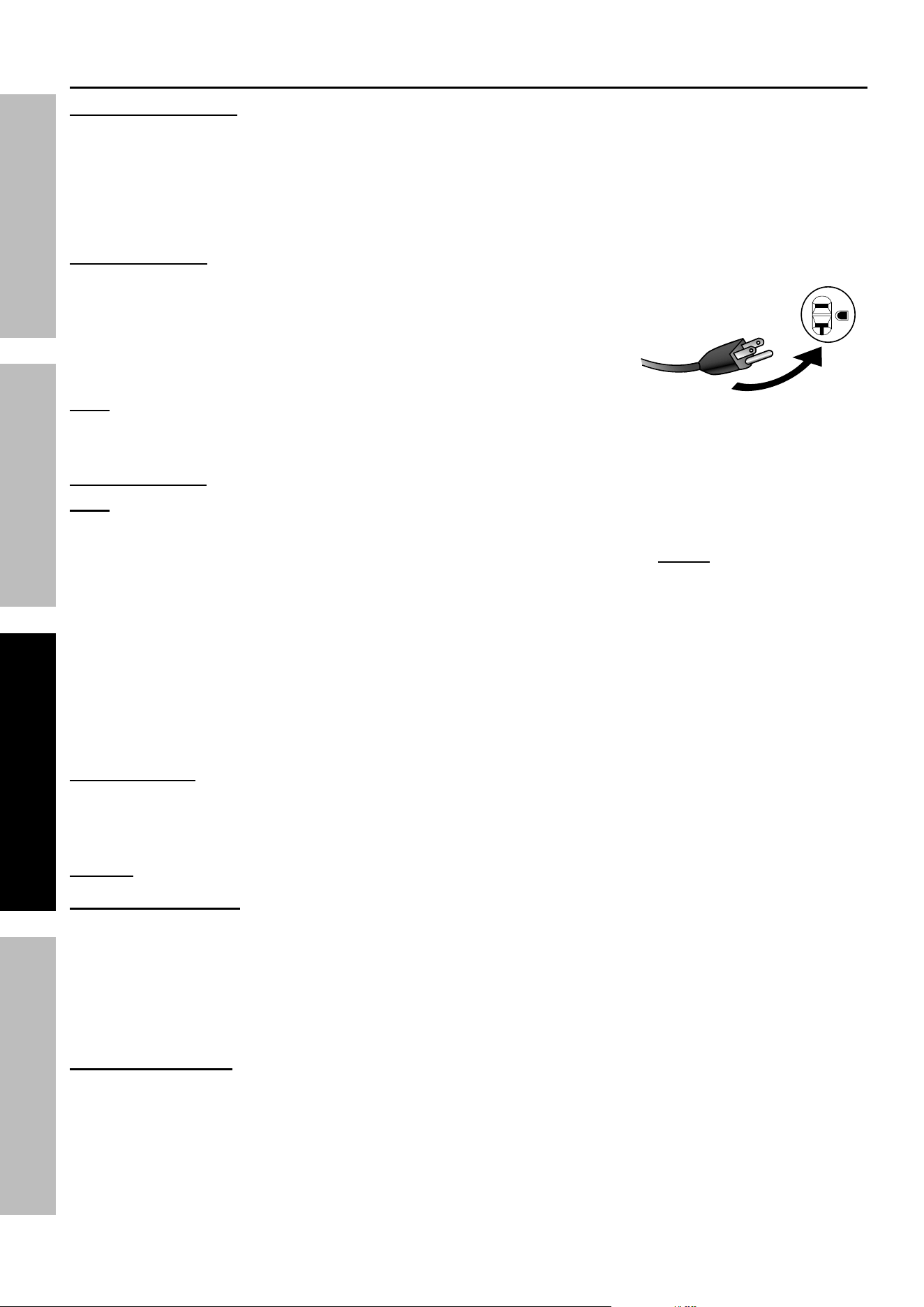
42. Extension Cord - Make sure your extension cord is
in good condition. When using an extension cord, be
sure to use one heavy enough to carry the current
your product will draw. An undersized extension
cord will cause a drop in line voltage resulting in loss
of power and overheating.
The table below shows the correct cord size to use
depending on cord length and nameplate ampere
rating. If in doubt, use the next heavier gauge.
The smaller the gauge number, the heavier the cord.
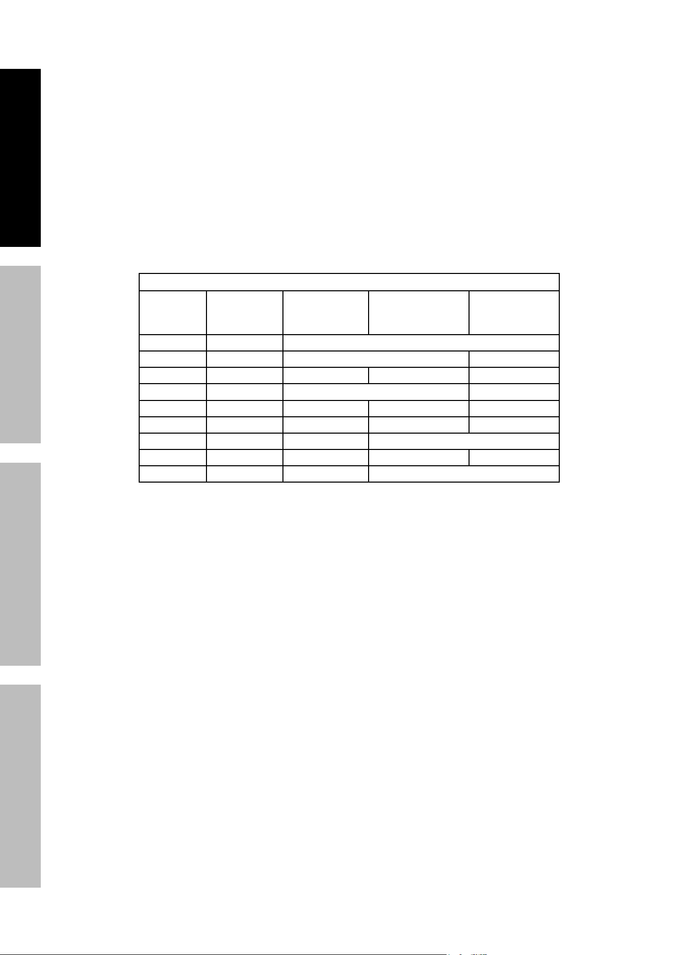
reCOMMenDeD MiniMuM Wire GauGe FOr eXTenSiOn COrDS
CurrenT
(aMpS)
Load @
120V
(WaTTS)
0 ~ 50 ft 50 ~ 75 ft 75 ~ 100 ft
2 240 18 AWG
4 480 18 AWG 16 AWG
6 720 18 AWG 16 AWG 14 AWG
8 960 16 AWG 12 AWG
10 1200 16 AWG 14 AWG 12 AWG
15 1800 14 AWG 12 AWG 10 AWG
20 2400 12 AWG 10 AWG
25 3000 12 AWG 10 AWG 8 AWG
30 3600 10 AWG 8 AWG
Page 7
For technical questions, please call 1-800-444-3353.
ITEM 71358
SaFeTyOperaTiOnMainTenanCe SeTup
parallel Kit precautions
TO preVenT SeriOuS inJury, DeaTH, anD GeneraTOr anD/Or
eQuipMenT DaMaGe FrOM eLeCTriC SHOCK anD Fire:
1. Follow parallel Kit instructions provided with
Kit for connection and use of a parallel Kit.
2. Only connect two identical Inverter Generators
together using a Parallel Kit.
3. Connect Parallel Kit only to terminals marked
“Parallel Outlets” on the front of the Generator.
4. Do not remove or connect a Parallel Kit
while the Generator is running.
5. Do not use a Parallel Kit that is
attached to only one Generator.
Service precautions
1. Before service, maintenance, or cleaning:
a. unplug all devices from the generator.
b. Turn the Combination Switch
to its “OFF” position.
c. allow the engine to completely cool.
d. Then, remove the spark plug cap
from the spark plug.
2. Keep all safety guards in place and in
proper working order. Safety guards include
muffler, air cleaner, mechanical guards,
and heat shields, among other guards.
3. Keep all electrical equipment clean and dry.
Replace any wiring where the insulation is
cracked, cut, abraded, or otherwise degraded.
Replace terminals that are worn, discolored, or
corroded. Keep terminals clean and tight.
4. Do not alter or adjust any part of the
equipment or its engine that is sealed by the
manufacturer or distributor. Only a qualified
service technician may adjust parts that may
increase or decrease governed engine speed.
5. Wear ANSI-approved safety goggles,
heavy-duty work gloves, and
dust mask/respirator during service.
6. Maintain labels and nameplates on the equipment.
These carry important information.
If unreadable or missing, contact
Harbor Freight Tools for a replacement.
7. Have the equipment serviced by a qualified repair
person using only identical replacement parts.
This will ensure that the safety of the equipment
is maintained. Do not attempt any service or
maintenance procedures not explained in this
manual or any procedures that you are uncertain
about your ability to perform safely or correctly.
8. Store equipment out of the reach of children.
9. Follow scheduled engine and
equipment maintenance.
refueling:
1. Do not refill the fuel tank while the
engine is running or hot.
2. Do not smoke, or allow sparks, flames,
or other sources of ignition around the
equipment, especially when refuelling.
3. Do not fill fuel tank to the top.
Leave a little room for the fuel to expand as needed.
4. Refuel in a well-ventilated area only.
5. Wipe up any spilled fuel and allow excess
to evaporate before starting engine.
To prevent Fire, do not start the engine
while the smell of fuel hangs in the air.
SaVe THeSe inSTruCTiOnS.
Page 8
For technical questions, please call 1-800-444-3353.
ITEM 71358
SaFeTy OperaTiOn MainTenanCeSeTup
Set up
read the enTire iMpOrTanT SaFeTy inFOrMaTiOn section at the beginning of this manual
including all text under subheadings therein before set up or use of this product.
TO preVenT SeriOuS inJury anD Fire: Operate only with proper spark arrestor installed.
Operation of this equipment may create sparks that can start fires around dry vegetation.
a spark arrestor may be required.
The operator should contact local fire agencies for laws or regulations relating to fire
prevention requirements.
At high altitudes, the engine’s carburetor, governor, and any other parts that control the fuel-air ratio
will need to be adjusted by a qualified mechanic to allow efficient high-altitude use and
to prevent damage to the engine and any other devices used with this product.
Grounding
The Generator must be properly grounded in
accordance with all relevant electrical codes and
standards before operation. In many locations, local
code will not require this generator to be grounded
when used with cord and plug equipment plugged
directly into the receptacles on the generator. However,
your local regulations may require the generator to be
grounded. Contact a licensed electrician or consult
local authorities regarding local grounding requirements.
If grounding is required, have the unit grounded by a
qualified electrician if you are not qualified to do so.
General grounding instructions are as follows:
Use one of the following as the grounding electrode:
Pipe or conduit, minimum ¾ in. diameter, minimum
8 ft. long. If steel, it must have anti-corrosion coating.
Rod, stainless steel or copper- or zinc-coated steel,
minimum 5/8 in. diameter, minimum 8 ft. long.
1. Drive electrode at least 8 ft.
vertically into the ground.
a. If rock layer prevents vertical entry, drive at an
angle not exceeding 45 degrees from vertical.
b. If rock layer prevents angle entry, bury electrode
in horizontal trench at least 30 in. deep.
2. The upper end of electrode must be
protected if above ground level.
3. Connect a #6 AWG grounding wire (not included)
from the Grounding Terminal on the Generator
Control Panel to the buried electrode.
For additional information on grounding methods,
please see the National Electrical Code.
nOTiCe: The portable generator Neutral conductor
is isolated from the frame and from the AC receptacle
ground pin. Electrical devices that require a
connection between one conductor pin and the
grounded receptacle pin may not function properly.
electric Starter Battery Connection
For the electric start function, the included 12 VDC
Battery must be connected before first use.
1. Remove the Battery Access Door.
2. Make sure the black strap stretches over the top of
the Battery and hooks into the Battery Platform.
3. Remove the covers from the Battery Terminals.
4. Locate the black and red battery cables.
5. Connect the red cable to the positive battery
terminal first. Then connect the black
cable to the negative battery terminal.
6. Replace the Battery Access Door.
Page 9
For technical questions, please call 1-800-444-3353.
ITEM 71358
SaFeTyOperaTiOnMainTenanCe SeTup
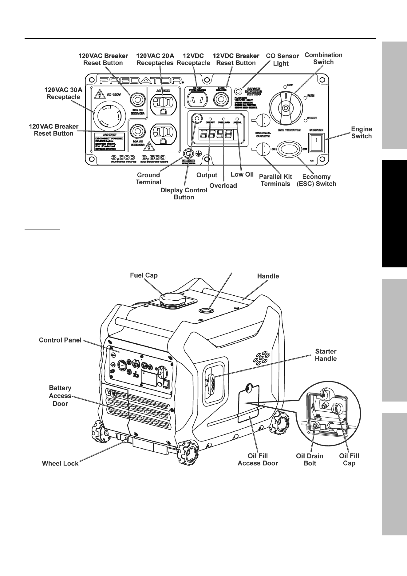
Components and Controls
Figure a: Control panel
WarninG! TO preVenT SeriOuS inJury: Follow parallel Kit instructions for
connection and use of a parallel Kit (parallel Kit and instructions sold separately).
Figure B: Generator Front
Fuel Gauge
Page 10
For technical questions, please call 1-800-444-3353.
ITEM 71358
SaFeTy OperaTiOn MainTenanCeSeTup
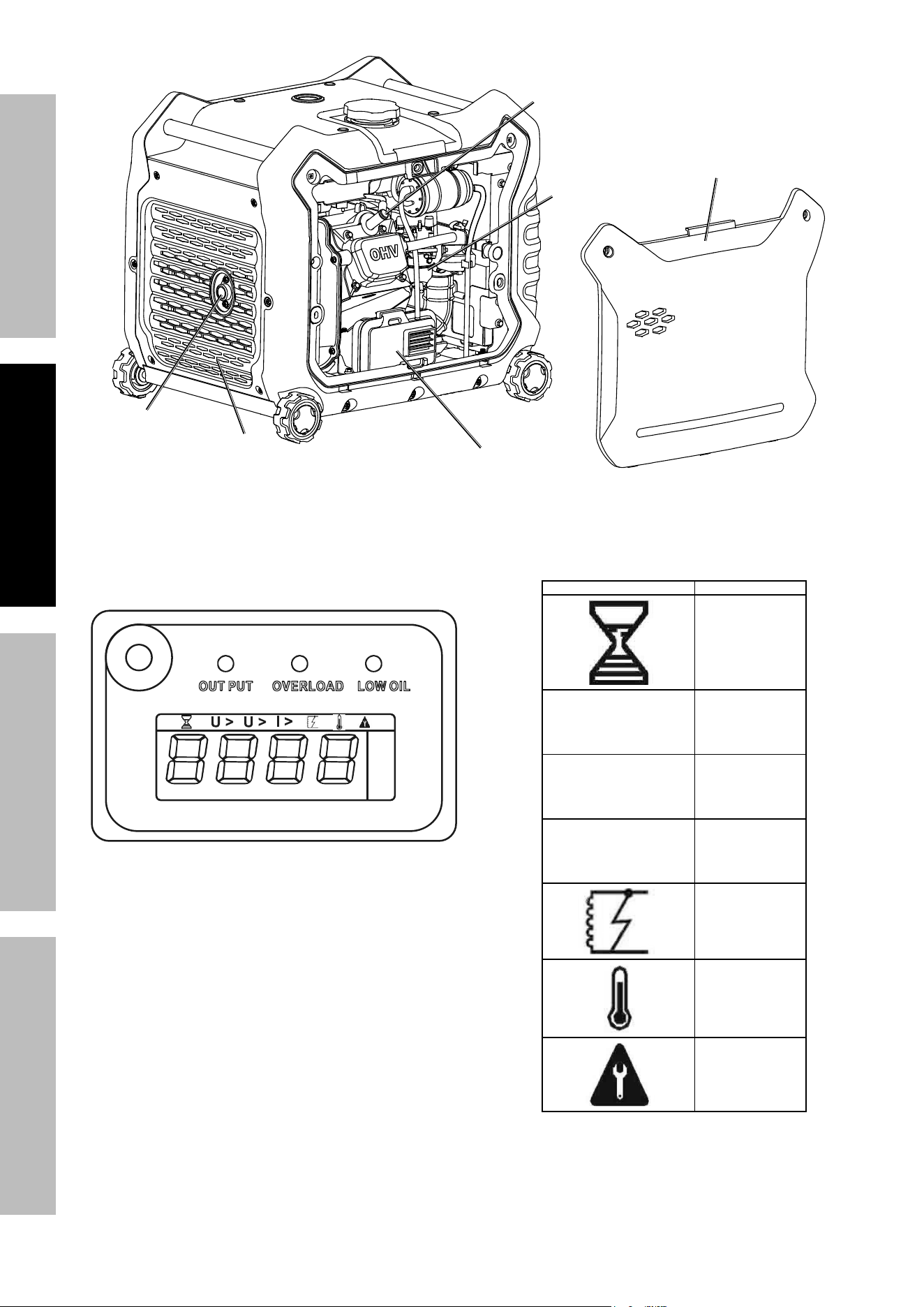
exhaust
Spark plug
air Filter
rear
Cover
access panel
Carburetor
Figure C: Generator rear and interior
Figure D: Display Screen Symbology
Symbol Meaning
Normal
u >
AC Overvoltage
u <
AC Undervoltage
i >
Generator Output
Overcurrent
Generator Output
Short Circuit
Inverter
Overheating
Maintenance Time
Page 11
For technical questions, please call 1-800-444-3353.
ITEM 71358
SaFeTyOperaTiOnMainTenanCe SeTup
Page 11
For technical questions, please call 1-800-444-3353.
ITEM 71358
High altitude Operation above 3000 feet
WarninG! TO preVenT SeriOuS inJury FrOM Fire:
Follow instructions in a well-ventilated area away from ignition sources.
If the engine is hot from use, shut the engine off and wait for it to cool before proceeding. Do not smoke.
nOTiCe: Warranty void if necessary adjustments are not made for high altitude use.
At high altitudes, the engine’s carburetor, governor, and any other parts that control the fuel-air ratio will need
to be adjusted by a qualified mechanic to allow efficient high-altitude use and to prevent damage to the engine
and any other devices used with this product. The fuel system on this engine may be influenced by operation
at higher altitudes. Proper operation can be ensured by installing an altitude kit at altitudes higher than 3000 ft.
above sea level. At elevations above 8000 ft, the engine may experience decreased performance, even with
the proper main jet. Operating this engine without the proper altitude kit installed may increase the engine’s
emissions and decrease fuel economy and performance. The kit should be installed by a qualified mechanic.
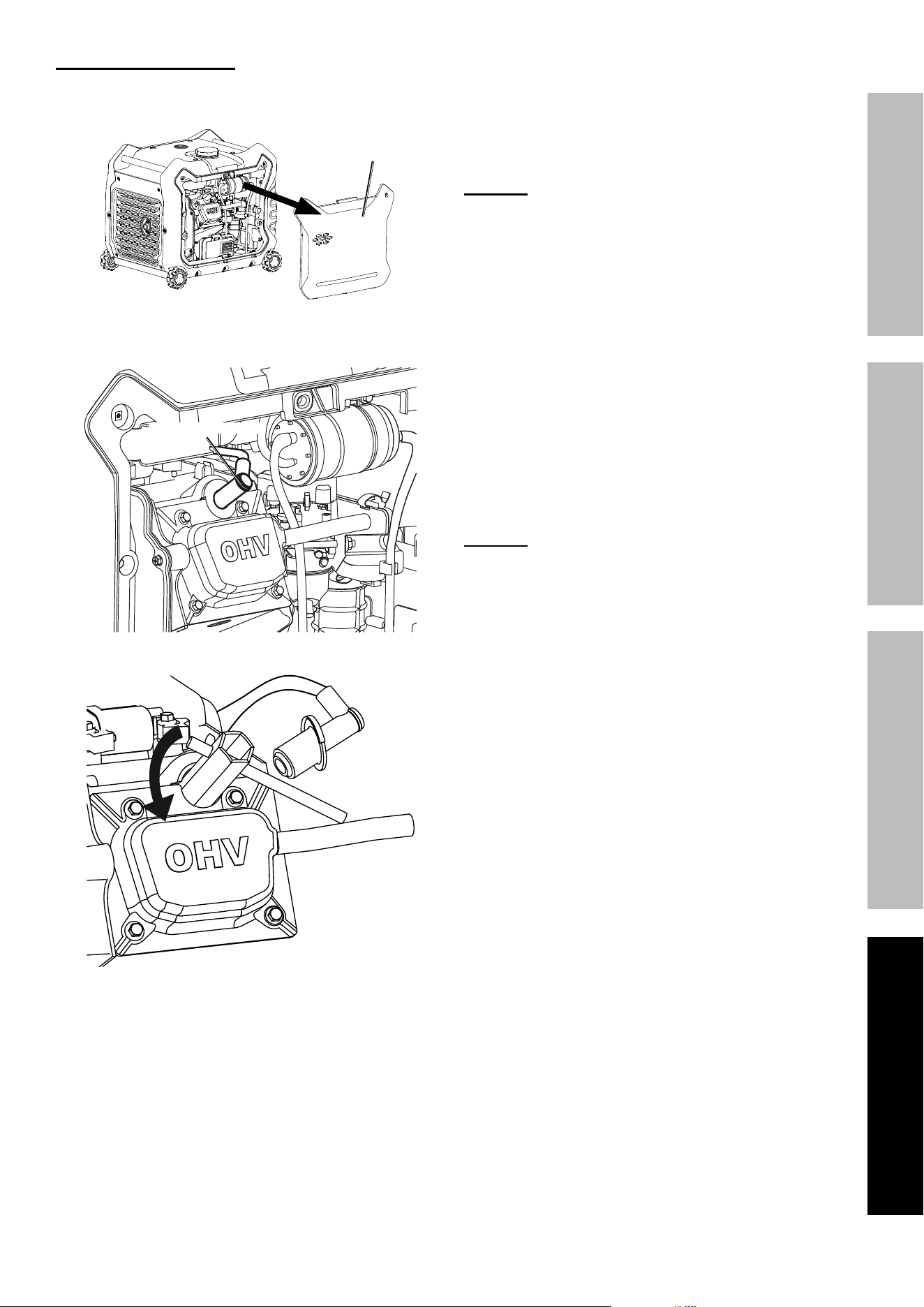
note: Not all Generator models have a Solenoid. Skip those steps if a Solenoid is not present.
1. Turn off the engine.
2. Close the fuel valve.
3. Open access panel. Remove air cleaner cover, elements, and air cleaner housing to expose carburetor.
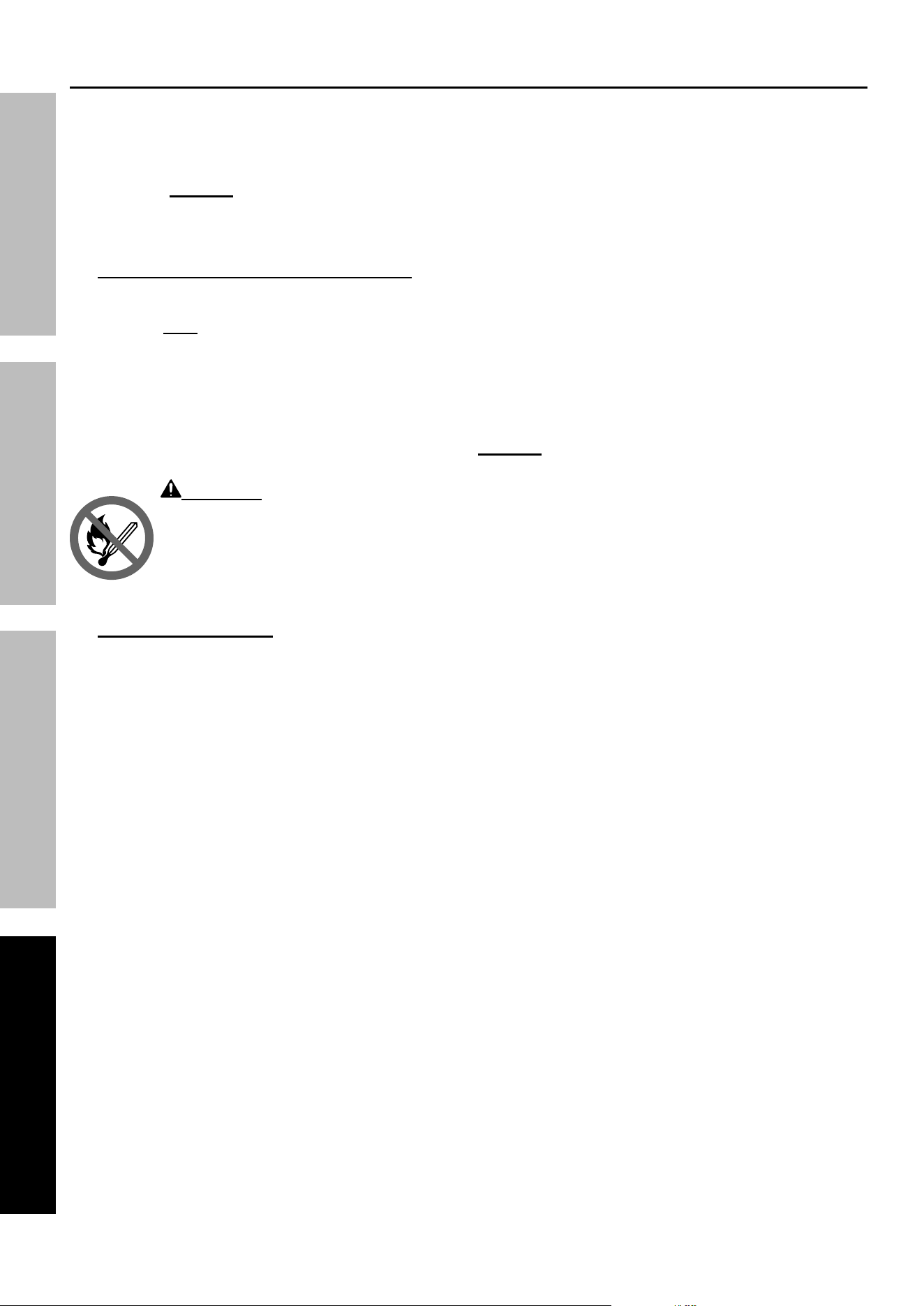
4. Unthread the screws holding the solenoid in place.
CauTiOn! Carburetor bowl may have gas in it which will leak upon removing the solenoid/bolt.
5. Disconnect the solenoid and solenoid seal from the bolt.
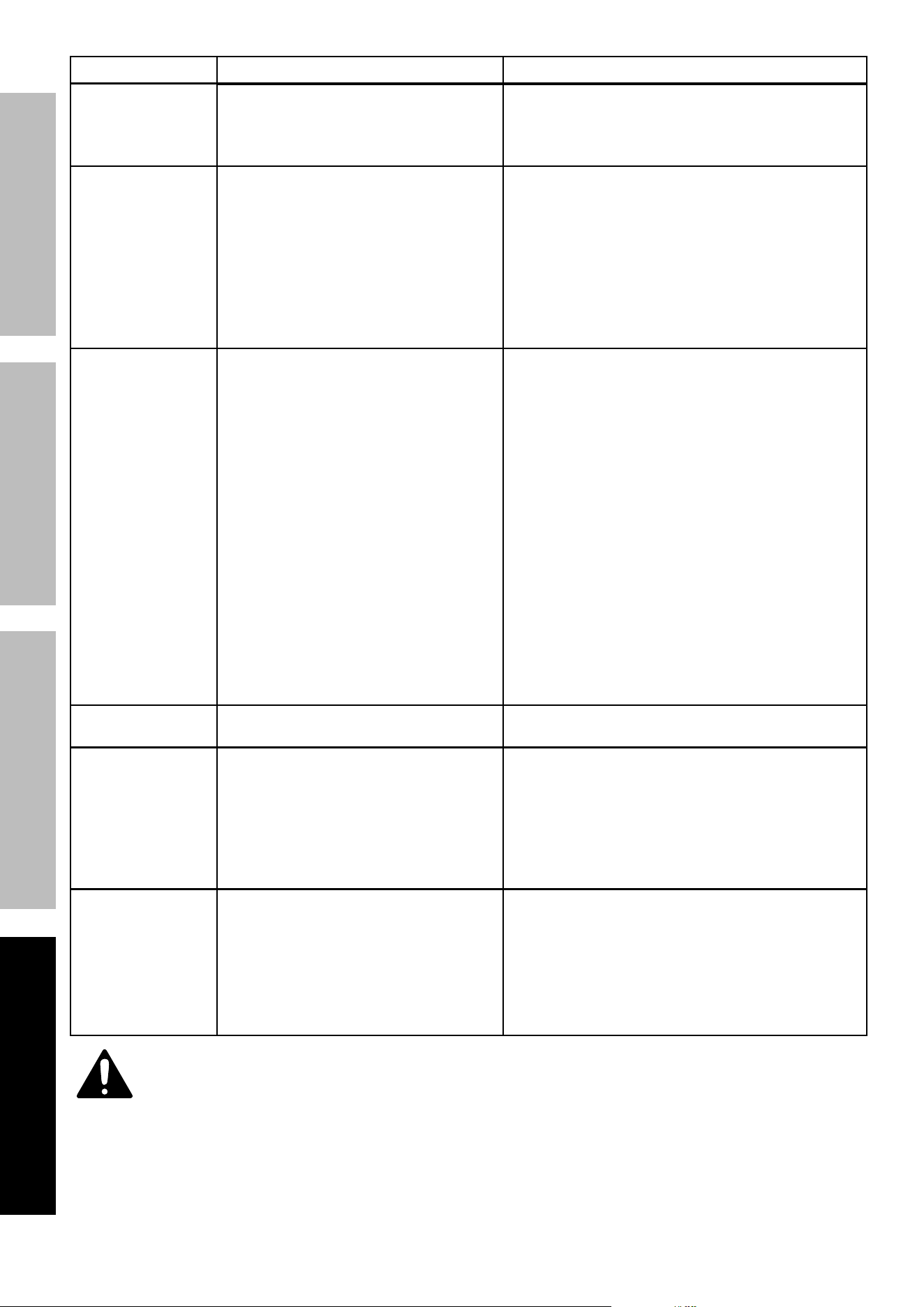
6. Unthread the bolt holding the fuel cup.
7. Remove the bolt, Bolt Seal, fuel cup, Fuel Cup Seal and Main Jet from the body of the carburetor assembly.
A carburetor screwdriver (not included) is needed to remove and install the Main Jet.
note: The mixing tube is held in place by the Main Jet and might fall out when it is removed.
If it falls out, replace it in the same orientation before replacing the Main Jet.
8. Replace the Main Jet with the replacement Main Jet
needed for your altitude range (part 1a or 2a).
note: The Fuel Cup Seal and Bolt Seal may be damaged during
removal and should be replaced with the new ones from the kit.
9. Replace the Fuel Cup Seal (4a), fuel cup,
Bolt Seal (3a), and bolt. Tighten in place.
nOTiCe: Do not cross thread bolt when tightening.
Finger tighten first and then use a wrench to
make sure the bolt is properly threaded.
10. Replace the solenoid and Solenoid Seal (5a),
and tighten in place with screws.
11. Reassemble the air cleaner and reattach all hoses to it.
12. Wipe up any spilled fuel and allow excess to evaporate before starting
engine. To prevent FIRE, do not start the engine while the smell of fuel
hangs in the air.
High altitude Kit parts List - a
part Description Qty
1a Main Jet 3000-6000 ft. 1
2a Main Jet 6000-8000 ft. 1
3a Bolt Seal 1
4a Fuel Cup Seal 1
5a Solenoid Seal 1
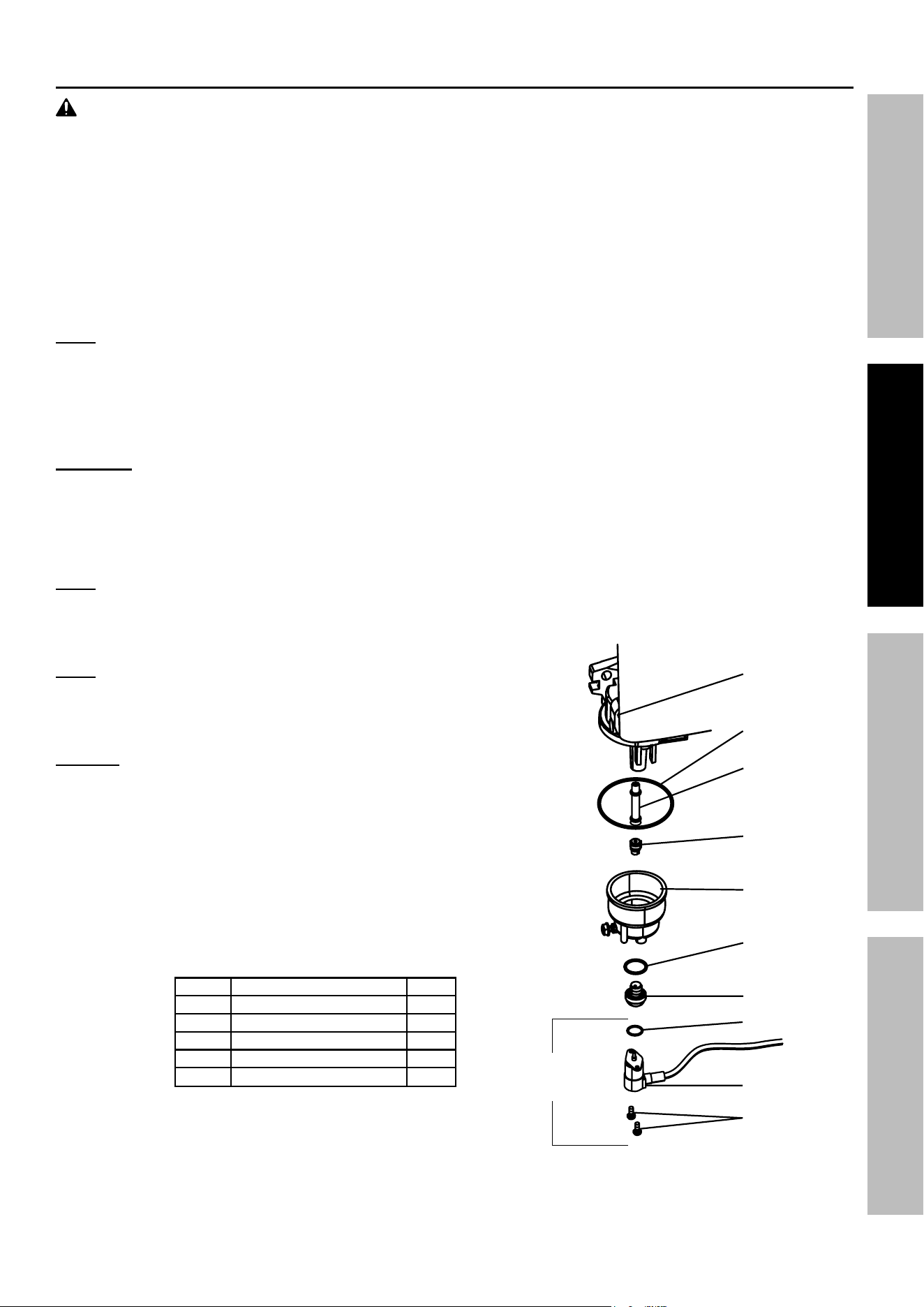
Carburetor
assembly
Main Jet
Fuel Cup Seal
Mixing Tube
(might remain
inside carburetor)
Fuel Cup
Bolt Seal
Bolt
Solenoid
Solenoid Seal
Screws
Not present
on some
Generators
Page 12
For technical questions, please call 1-800-444-3353.
ITEM 71358
SaFeTy OperaTiOn MainTenanCeSeTup
Operation
read the enTire iMpOrTanT SaFeTy inFOrMaTiOn section at the beginning of this manual
including all text under subheadings therein before set up or use of this product.
pre-Start Checks
Inspect Engine and Generator looking for damaged, loose, and missing parts before set up and starting.
If any problems are found, do not use equipment until fixed properly.
Checking and Filling engine Oil
nOTiCe: Generator is shipped without engine
oil. engine’s crankcase MuST be filled with
oil before first use. your Warranty is VOiD if
the engine’s crankcase is not properly filled
with oil before first use and before each use
thereafter. Before each use, check the oil level.
engine will not start with low or no engine oil.
1. Make sure the Engine is stopped and is level.
2. On the left side of the Generator, loosen
the Screw and remove the Oil Fill
Access Door, as shown to the right.
3. Clean the top of the Oil Fill Cap / Dipstick
and the area around it. Remove the
Cap / Dipstick, turning it counterclockwise.
4. Check the oil level. The oil level should be
up to the edge of the hole as shown.
5. As needed, add the appropriate type of
oil until the oil level is at the proper level.
SAE 10W-30 oil is recommended for general use.
6. Thread the Oil Fill Cap / Dipstick back in clockwise
and replace the Oil Fill Access Door.
nOTiCe: Do not run the engine with too little oil.
engine will shut off if engine oil level is too low.
Oil Fill
access
Door
Full Level
x
x
x x
x x
x
Oil Fill
Cap / Dipstick
Checking and Filling Fuel
WarninG! TO preVenT SeriOuS
inJury FrOM Fire:
Fill the fuel tank in a well-ventilated area
away from ignition sources. If the Engine
is hot from use, shut the Engine off and
wait for it to cool before adding fuel. Do not smoke.
1. Clean the Fuel Cap and the area around it.
2. Unscrew and remove the Fuel Cap.
3. Remove the Strainer and remove any dirt
and debris. Then replace the Strainer.
note: Do not use gasoline containing more than
10% ethanol (e10). Do not use e85 ethanol. add fuel
stabilizer to the gasoline or the Warranty is VOiD.
note: Do not use gasoline that has been stored in a
metal fuel container or a dirty fuel container. it can
cause particles to enter the carburetor, affecting
engine performance and/or causing damage.
4. If needed, fill the Fuel Tank to about 1 inch under
the fill neck of the Fuel Tank with 87 octane or
higher unleaded gasoline that has been treated
with a fuel stabilizer additive. Follow fuel stabilizer
manufacturer’s recommendations for use.
5. Replace the Fuel Cap.
6. Wipe up any spilled fuel and allow excess
to evaporate before starting engine.
To prevent FIRE, do not start the engine
while the smell of fuel hangs in the air.
Page 13
For technical questions, please call 1-800-444-3353.
ITEM 71358
SaFeTyOperaTiOnMainTenanCe SeTup
Starting the engine
Before Starting the engine
a. inspect the generator and engine.
b. Disconnect all electrical loads from the generator.
c. Fill the engine with the proper amount and type of
both stabilizer-treated unleaded gasoline and oil.
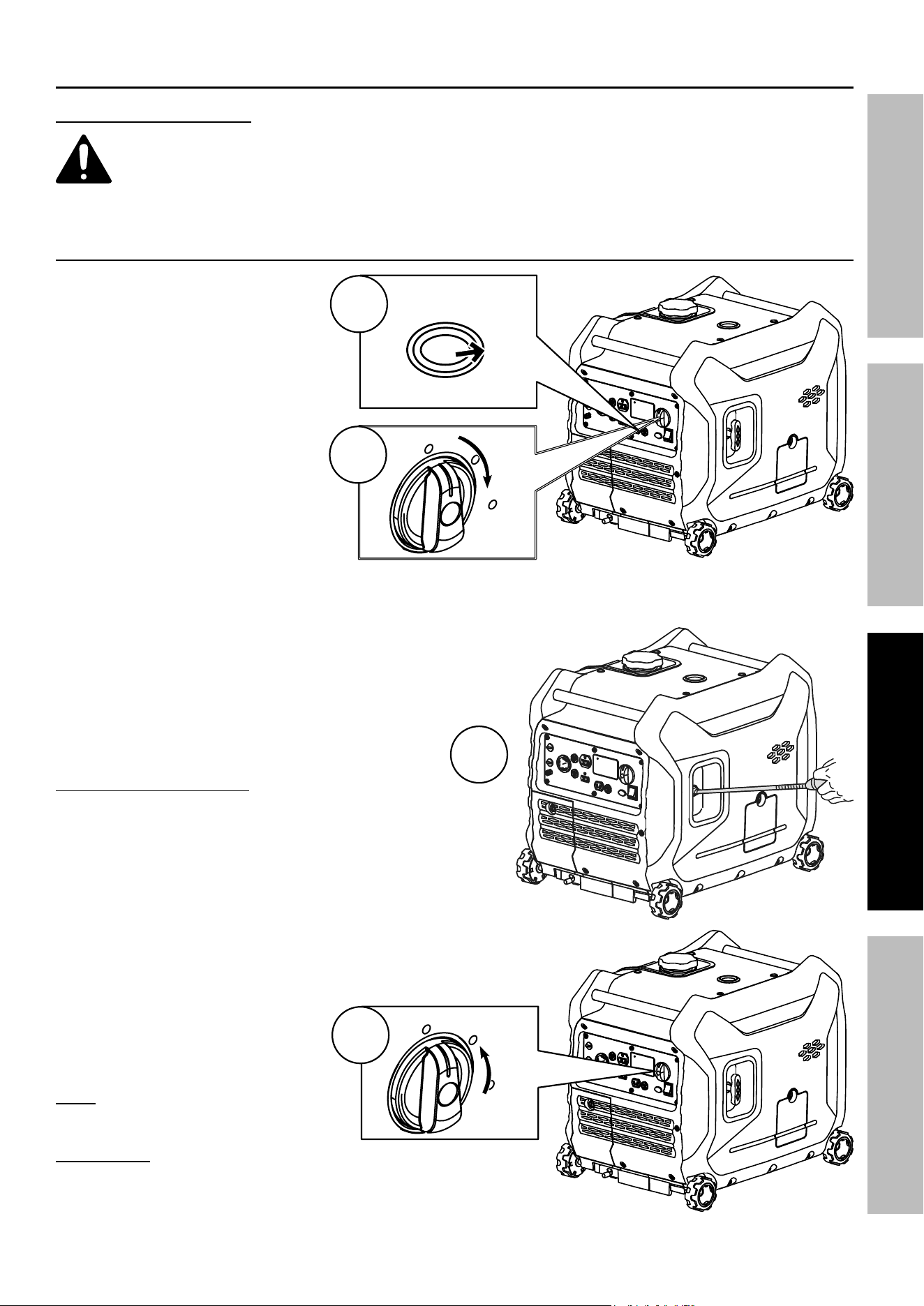
Manual Start
1. Move the Economy (ESC)
Switch to the OFF position.
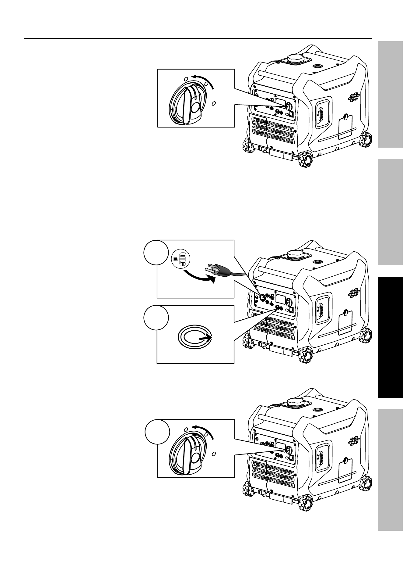
2. Turn the Combination Switch
to the START position.
3. Grip the Starter Handle of the Engine loosely and
pull it slowly several times to allow the gasoline to flow
into the Engine’s carburetor. Then pull the Starter
Handle gently until resistance is felt. Allow
Cable to retract fully and then pull it quickly.
Repeat until the Engine starts. Do not let the
Starter Handle snap back against the housing.
Hold it as it recoils so it doesn't hit the housing.
if engine does not start:
• Check engine oil level.
Engine will not start with low or no engine oil.
• Check spark arrestor cleanliness.
Engine will not start if spark arrestor is clogged.
• For warm engine – turn Combination Switch
to RUN before trying to start it again.
4. The OUTPUT light illuminates when
the Engine starts and the Generator
produces power. Allow the Engine
to run for several seconds, then
move the Combination Switch
slowly to its RUN position.
note: Moving the Combination
Switch too fast could stall the Engine.
iMpOrTanT: Allow the Engine to run
at no load for five minutes after each
start-up so that the Engine can stabilize.
STarT
OFF
run
2
eSC THrOTTLe
On OFF
1
3
STarT
OFF
run
Move
Slowly
4
Page 14
For technical questions, please call 1-800-444-3353.
ITEM 71358
SaFeTy OperaTiOn MainTenanCeSeTup
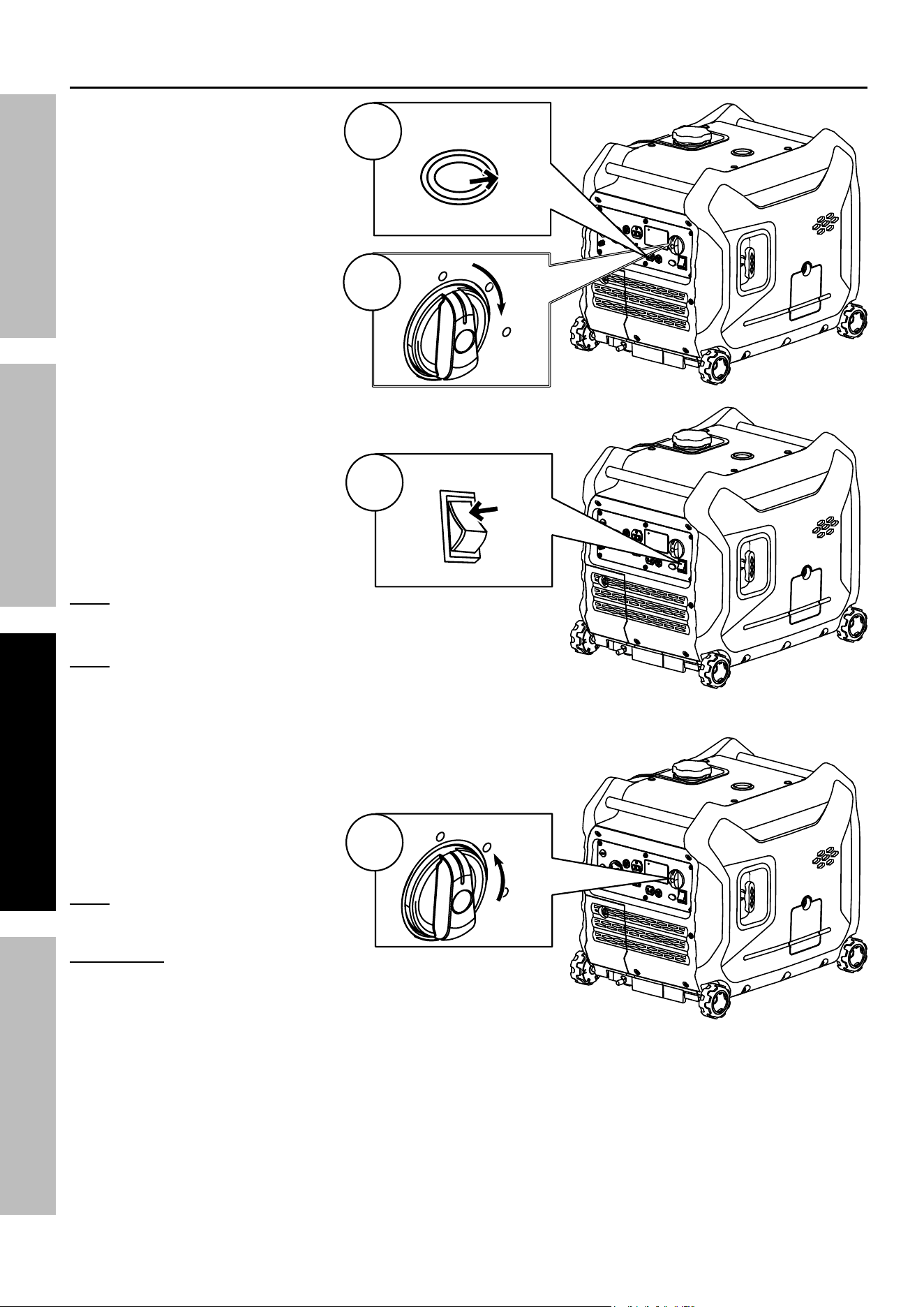
electric Start
1. Move the Economy (ESC)
Switch to the OFF position.
2. Turn the Combination Switch
to the START position.
3. Press and hold the Starter Button
to start the Engine. If Engine
does not start within 3 seconds,
release Starter Button. Wait at
least 10 seconds, then try again.
note: If engine does not start, check
engine oil level. Engine will not
start with low or no engine oil.
note: If warm engine does not start,
turn Combination Switch to RUN
before trying to start it again.
4. The OUTPUT light illuminates when
the Engine starts and the Generator
produces power. Allow the Engine
to run for several seconds, then
move the Combination Switch
slowly to its RUN position.
note: Moving the Combination
Switch too fast could stall the Engine.
iMpOrTanT: Allow the Engine to run
at no load for five minutes after each start-up
so that the Engine can stabilize.
STarT
OFF
run
2
eSC THrOTTLe
On OFF
1
STarTer
3
STarT
OFF
run
Move
Slowly
4
Page 15
For technical questions, please call 1-800-444-3353.
ITEM 71358
SaFeTyOperaTiOnMainTenanCe SeTup
Break-in period
a. Breaking-in the Engine will help to ensure proper equipment and Engine operation.
b. The break-in period will last about 30 hours of use.
DO NOT exceed 75% of the Generator’s running wattage during this period.
• Change the engine oil after this period.
Under normal operating conditions subsequent maintenance follows
the schedule explained in the MainTenanCe section.
CarBOn MOnOXiDe SHuTOFFCarBOn MOnOXiDe SHuTOFF
DanGer! TO preVenT SeriOuS inJury anD DeaTH FrOM CarBOn MOnOXiDe inHaLaTiOn:
The Carbon Monoxide sensor is an additional layer of protection only. Do not use the Generator in any area
or situation that will allow carbon monoxide to accumulate.
• FLASHING RED LIGHT:
Dangerous levels of carbon monoxide gas
have built up. Leave immediately until
area has aired out. Move Generator to
well-ventilated area before operation.
• FLASHING YELLOW LIGHT:
Carbon monoxide sensor malfunction.
Sensor needs service. Call 1-800-444-3353 as
soon as possible. Do not use the Generator until
the sensor is working properly.
NOTE: Yellow light flashes once
after starting to indicate passing self-
check and is functioning normally.
Carbon Monoxide sensor must only be serviced by qualified technician to restore it to original
settings. Do not modify or tamper with the Carbon Monoxide sensor. not following these
instructions can result in death or serious injury due to Carbon Monoxide sensor malfunction.
Nominal 12 VDC Output
1. Move the Economy (ESC) Switch
to the OFF position.
2. Only use the 12 VDC receptacle
to charge a 12 volt lead-acid
type battery using an appropriate
charge controller. (Battery and
controller not included.) The
12 VDC output is not regulated.
3. Do not connect any device
to the 12 VDC terminal that
draws more than 8 amps.
4. If this 12 VDC circuit protection is
tripped, reduce the load, and press the
Reset Button next to the outlet.
eSC THrOTTLe
On OFF
DC 12 V
8 A MAX
reSeT
Page 16
For technical questions, please call 1-800-444-3353.
ITEM 71358
SaFeTy OperaTiOn MainTenanCeSeTup
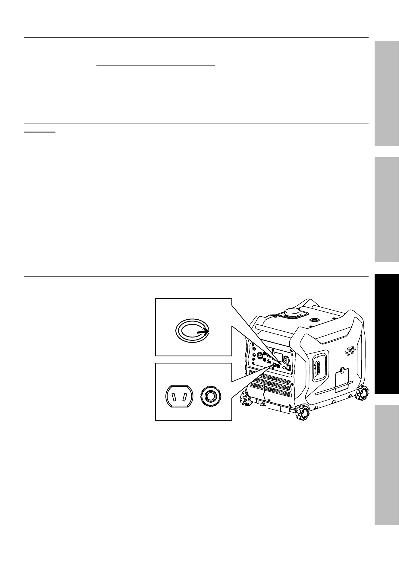
Connecting 120 VaC Loads to the Generator
Calculate power Draw:
Power draw can be calculated by multiplying volts and amps. The resulting number is wattage.
• Never exceed the running wattage for the Generator or any outlet amperage rating.
• Refer to appliance/tool owner’s manuals to determine the wattage of electrical load devices.
• Long power cords and extension cords draw additional power. Keep cord length at a minimum.
Wattage estimates
Refer to your device documentation for start-up and running wattage
requirements.
Check nameplate wattages on all loads before connecting to Generator.
Plug the power cord of the 120 volt appliance/tool into the 120 VAC Outlet
on the Generator. Plug in appliances from largest to smallest load.
note: Do not allow the Generator to completely run out of fuel with devices
attached. a Generator’s output may sharply spike as it runs out of fuel,
causing damage to attached devices.
Overload indicator
note: The OVERLOAD light may turn on for a few seconds as a large device starts up.
This is normal for loads approaching the capacity of this Generator.
1. The total combined load through the outlet on the Generator must not exceed the running power of the unit.
2. If the OVERLOAD light turns on and the Generator stops producing power, it has been overloaded.
3. Turn off and disconnect all electrical devices and stop the Engine. Compare device
requirements to Generator rating and reduce the total wattage of connected devices if
necessary. Move anything that may be limiting Generator ventilation away.
4. Check if any circuit breakers have tripped and make sure that ALL circuit
breakers are reset before starting the Generator again.
5. Restart the Engine and reconnect devices while being careful to not overload Generator.
Low Oil indicator
1. If the Engine oil level is too low, the LOW OIL light turns on and the Engine will automatically shut off.
2. The Engine cannot be restarted until the proper amount of oil has been added. Add the appropriate
type of oil until the oil level is at the proper level. SAE 10W-30 oil is recommended for general use.
nOTiCe: Do not run the engine with too little oil. engine will shut off if engine oil level is too low.
economy (eSC) Switch
1. Turn the Economy (ESC) Switch ON to limit noise and fuel consumption for lighter generator loads.
2. Turn the Economy (ESC) Switch OFF to operate engine at full speed:
a. when starting
b. when a heavy load is applied
c. when using the 12 VDC output
Digital Display Screen
The Display Screen can be used to monitor the operating status of the Generator. Use
the Display Control Button to scroll through the following indicators:
• V – Voltage
• A – Amperage
• VA – Volt Amps / Watts
• Hour – current run time and accumulative run time
Plug Load In
Page 17
For technical questions, please call 1-800-444-3353.
ITEM 71358
SaFeTyOperaTiOnMainTenanCe SeTup
Stopping the engine
To stop the Engine in an emergency,
turn the Combination Switch OFF.
Under normal conditions, use the following procedure to shut off the Generator:
1. Turn all electrical load devices off and
unplug them from the Generator.
2. If the Economy (ESC) Switch is ON,
turn it to the OFF position.
3. Turn the Combination Switch OFF.
STarT
OFF
run
eMerGenCy
SHuT OFF
unplug Loads
1
eSC THrOTTLe
On OFF
2
STarT
OFF
run
3
Page 18
For technical questions, please call 1-800-444-3353.
ITEM 71358
SaFeTy OperaTiOn MainTenanCeSeTup
Maintenance
WarninG
TO preVenT SeriOuS inJury FrOM aCCiDenTaL STarTinG:
Turn the Combination Switch of the equipment to its “OFF” position, wait for the engine to cool, and
disconnect the spark plug cap before performing any inspection, maintenance, or cleaning procedures.
TO preVenT SeriOuS inJury FrOM eQuipMenT FaiLure:
Do not use damaged equipment. if abnormal noise, vibration, or
excess smoking occurs, have the problem corrected before further use.
Follow all service instructions in this manual. The engine may fail critically if not serviced properly.
Many maintenance procedures, including any not detailed in this manual, will need to be performed
by a qualified technician for safety. if you have any doubts about your ability to safely service the
equipment or engine, have a qualified technician service the equipment instead.
Cleaning, Maintenance, and Lubrication Schedule
note: This maintenance schedule is intended solely as a general guide. If performance decreases or if
equipment operates unusually, check systems immediately. The maintenance needs of each piece of equipment
will differ depending on factors such as duty cycle, temperature, air quality, fuel quality, and other factors.
note: The following procedures are in addition to the regular checks and maintenance
explained as part of the regular operation of the engine and equipment.
procedure
Before
each use
Monthly or
every 8 hr.
of use
every 3 mo.
or 50 hr.
of use
every 6 mo.
or 100 hr.
of use
yearly or
every 300 hr.
of use
every
2 years
page
1. Brush off outside of engine
2. Check engine oil level
3. Check air filter
Change engine oil
19
Clean/replace air cleaner
*
20
1. Check and clean spark plug
2. Check and clean spark arrestor
21
1. Check/adjust idle speed
2. Check/adjust valve clearance
3. Clean fuel tank, strainer
and carburetor
4. Clean carbon build-up from
combustion chamber
**
–
Replace fuel line if necessary
**
–
*Service more frequently when used in dusty areas.
**These items should be serviced by a qualified technician.
Page 19
For technical questions, please call 1-800-444-3353.
ITEM 71358
SaFeTyOperaTiOnMainTenanCe SeTup
Checking and Filling Fuel
WarninG! TO preVenT SeriOuS
inJury FrOM Fire:
Fill the fuel tank in a well-ventilated area
away from ignition sources. if the
engine is hot from use, shut the engine
off and wait for it to cool before adding fuel.
Do not smoke.
1. Clean the Fuel Cap and the area around it.
2. Unscrew and remove the Fuel Cap.
3. Remove the Strainer and remove any dirt
and debris. Then replace the Strainer.
note: Do not use gasoline containing more than
10% ethanol (e10). Do not use e85 ethanol. add fuel
stabilizer to the gasoline or the Warranty is VOiD.
note: Do not use gasoline that has been stored in a
metal fuel container or a dirty fuel container. it can
cause particles to enter the carburetor, affecting
engine performance and/or causing damage.
4. If needed, fill the Fuel Tank to about 1 inch under
the fill neck of the Fuel Tank with 87 octane or
higher unleaded gasoline that has been treated
with a fuel stabilizer additive. Follow fuel stabilizer
manufacturer’s recommendations for use.
5. Replace the Fuel Cap.
6. Wipe up any spilled fuel and allow excess
to evaporate before starting engine.
To prevent FIRE, do not start the engine
while the smell of fuel hangs in the air.
engine Oil Change
CauTiOn! Oil is very hot during operation and can cause burns. Wait for engine to cool before changing oil.
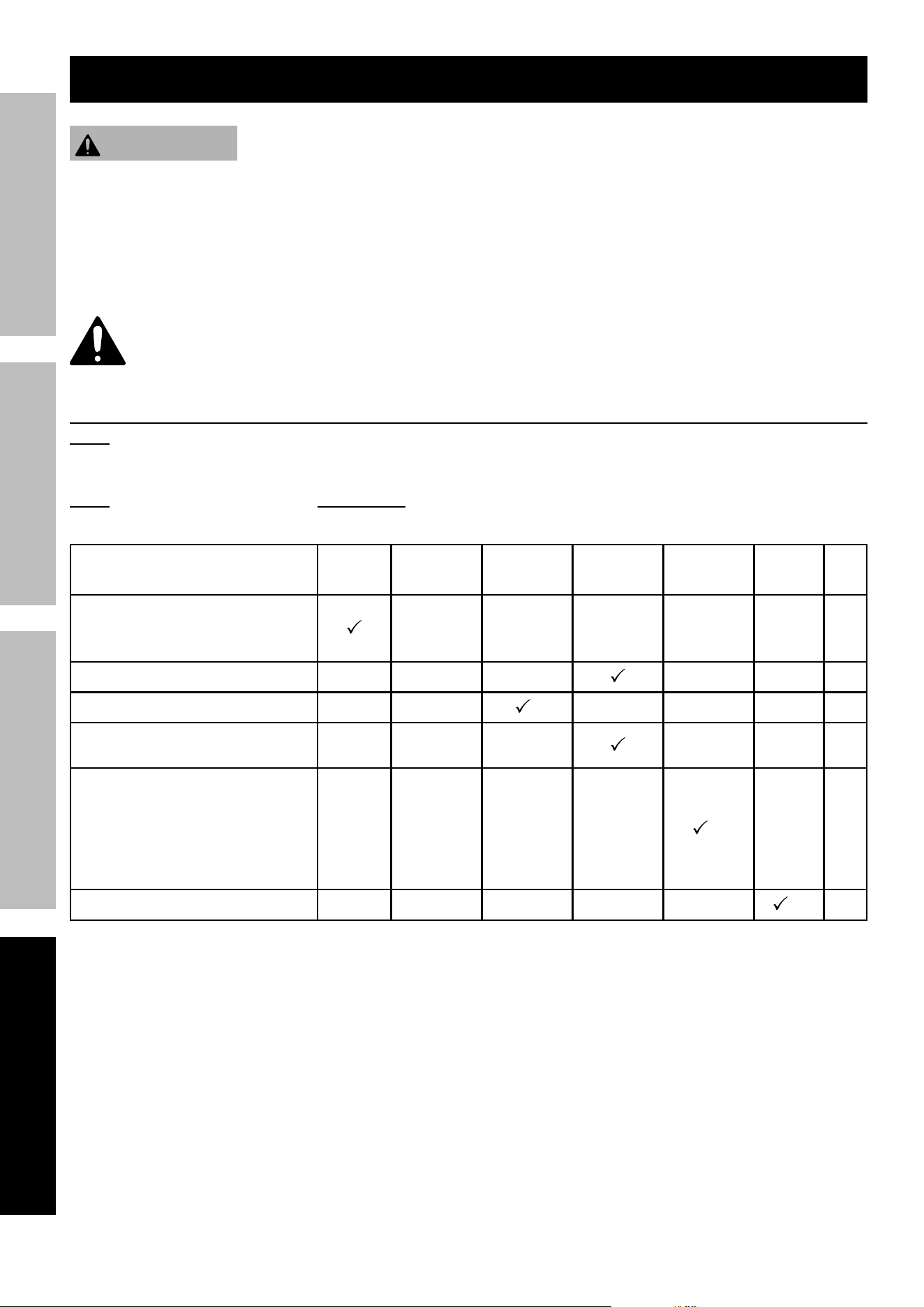
1. Make sure the Engine is stopped and is level.
2. On the right side of the Generator,
loosen the Screw and remove the Oil Fill
Access Door, as shown to the right.
3. Pull the Oil Drain Hose out of the Generator.
4. Clean the top of the Oil Fill Cap / Dipstick
and the area around it. Remove the
Cap / Dipstick, turning it counterclockwise.
5. Place an oil drain pan under the Generator
and center under the Oil Drain Hose opening.
Remove the Oil Drain Cap, tilt the Generator
slightly to facilitate drainage and wait for oil
to drain completely. Recycle used oil.
6. Replace the Oil Drain Cap. Put the Oil
Drain Hose back into the Generator.
7. Add the appropriate type of oil until
the oil level is at the proper level.
SAE 10W-30 oil is recommended for general use.
note: Make sure Generator is level when adding oil to
prevent overfilling which could cause engine damage.
8. Check the oil level. The oil level should be
up to the edge of the hole as shown.
9. Thread the Oil Fill Cap / Dipstick back in clockwise
and replace the Oil Fill Access Door.
nOTiCe: Do not run the engine with too little oil.
engine will not start with low or no engine oil.
Oil Fill
access
Door
Full Level
Oil Fill
Cap / Dipstick
Oil Drain Cap
Page 20
For technical questions, please call 1-800-444-3353.
ITEM 71358
SaFeTy OperaTiOn MainTenanCeSeTup
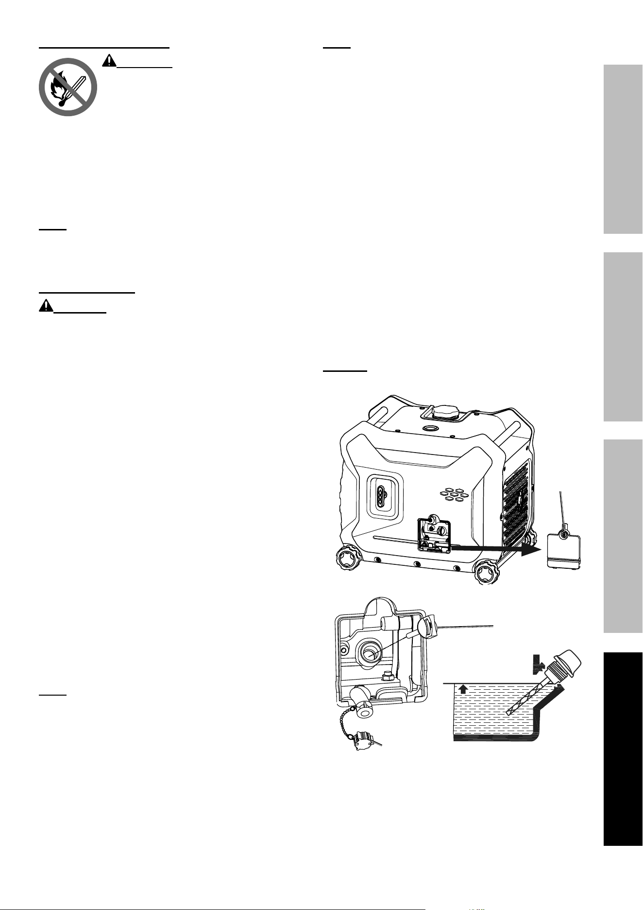
air Filter element Maintenance
1. Loosen two screws and remove the Access
Panel on the left side of the Generator.
access
panel
2. Remove the Air Filter Cover and the
air filter elements and check for dirt.
Clean as described below.
air Filter air Filter
CoverCover
3. Cleaning:
• For “paper” filter elements:
To prevent injury from dust and debris,
wear ANSI-approved safety goggles,
NIOSH-approved dust mask/respirator, and
heavy-duty work gloves. In a well-ventilated
area away from bystanders, use pressurized
air to blow dust out of the air filter.
• For foam filter elements:
Wash the element in warm water and
mild detergent several times. Rinse.
Squeeze out excess water and allow it to dry
completely. Soak the filter in lightweight oil
briefly, then squeeze out the excess oil.
4. Install the cleaned filter.
5. Secure the Air Filter Cover and replace the
Access Panel before use.
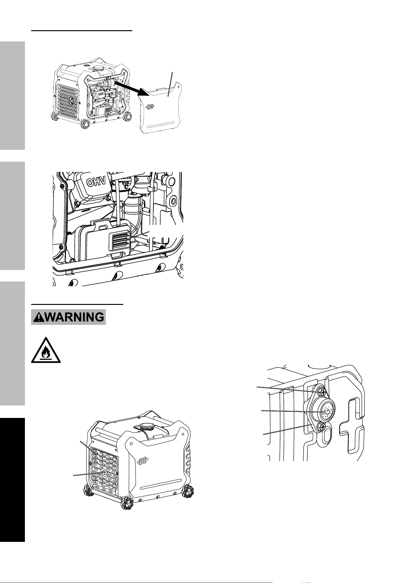
Spark arrestor Maintenance
TO preVenT SeriOuS inJury anD Fire: Operate only with proper spark arrestor installed.
Operation of this equipment may create sparks that can start fires around dry vegetation.
a spark arrestor may be required. The operator should contact local fire agencies for laws or
regulations relating to fire prevention requirements.
1. Allow the Generator to cool completely.
2. Remove the 6 Screws (79) from
the back of the Generator.
3. Remove the Grate (149).
Grate (149)
Spark
arrestor
4. Remove the two Bolts that hold the
Spark Arrestor Bracket in place.
Bolt
Bracket
Spark
arrestor
5. Clean the Spark Arrestor using a wire brush
(sold separately). Replace arrestor if damaged.
6. WarninG! TO preVenT SeriOuS inJury
FrOM aCCiDenTaL BruSH Fire, secure
Spark arrestor back in place immediately
after cleaning and before further operation.
Page 21
For technical questions, please call 1-800-444-3353.
ITEM 71358
SaFeTyOperaTiOnMainTenanCe SeTup
Spark plug Maintenance
1. Loosen two screws and remove the Access
Panel on the left side of the Generator.
access
panel
2. Disconnect spark plug cap from end of plug.
Clean out debris from around spark plug.
Spark plug CapSpark plug Cap
3. Using a spark plug wrench, remove the spark plug.
4. Inspect the spark plug:
If the electrode is oily, clean it using a clean, dry rag.
If the electrode has deposits on it, polish it using
emery paper. If the white insulator is cracked or
chipped, the spark plug needs to be replaced.
nOTiCe: Use only F7RTC type spark plug or equivalent.
Using an incorrect spark plug may damage the engine.
5. When installing a new spark plug,
adjust the plug’s gap to the specification on the
Specifications chart. Do not pry against the
electrode, the spark plug can be damaged.
6. Apply anti-seize material to Spark Plug threads.
Install the new spark plug or
the cleaned spark plug into the engine.
• Gasket-style:
Finger-tighten until the gasket
contacts the cylinder head,
then tighten about 1/2-2/3 turn more.
• non-gasket-style:
Finger-tighten until the plug
contacts the cylinder head,
then tighten about 1/16 turn more.
nOTiCe: Tighten the spark plug properly.
if loose, the spark plug will cause the
engine to overheat.
if overtightened, the threads in the
engine block will be damaged.
7. Apply dielectric spark plug boot protector
(not included) to the end of the spark plug
and reattach the cap securely.
8. Replace Spark Plug Access Cover
and Access Panel.
Page 22
For technical questions, please call 1-800-444-3353.
ITEM 71358
SaFeTy OperaTiOn MainTenanCeSeTup
Storage
When the equipment is to remain idle for longer than
20 days, prepare the engine for storage as follows:
1. CLeaninG:
Wait for engine to cool, then clean engine with
dry cloth. nOTiCe: Do not clean using water.
The water will gradually enter the
engine and cause damage.
2. FueL:
Gasoline Treatment/Draining the Fuel Tank
To protect the fuel tank during storage, fill the
tank with fresh gasoline that has been treated
with a fuel stabilizer additive. Follow fuel
stabilizer manufacturer’s recommendations
for use. Refer to Checking and Filling Fuel
Checking and Filling Fuel on page 11.
Aged gasoline that has not been treated with
stabilizer ahead of time must be safely drained
away and not run through the engine.
WarninG! TO preVenT SeriOuS
inJury FrOM Fire:
Fill tank in a well-ventilated area away
from ignition sources. if the engine
is hot from use, shut the engine off and
wait for it to cool before adding fuel.
Do not smoke.
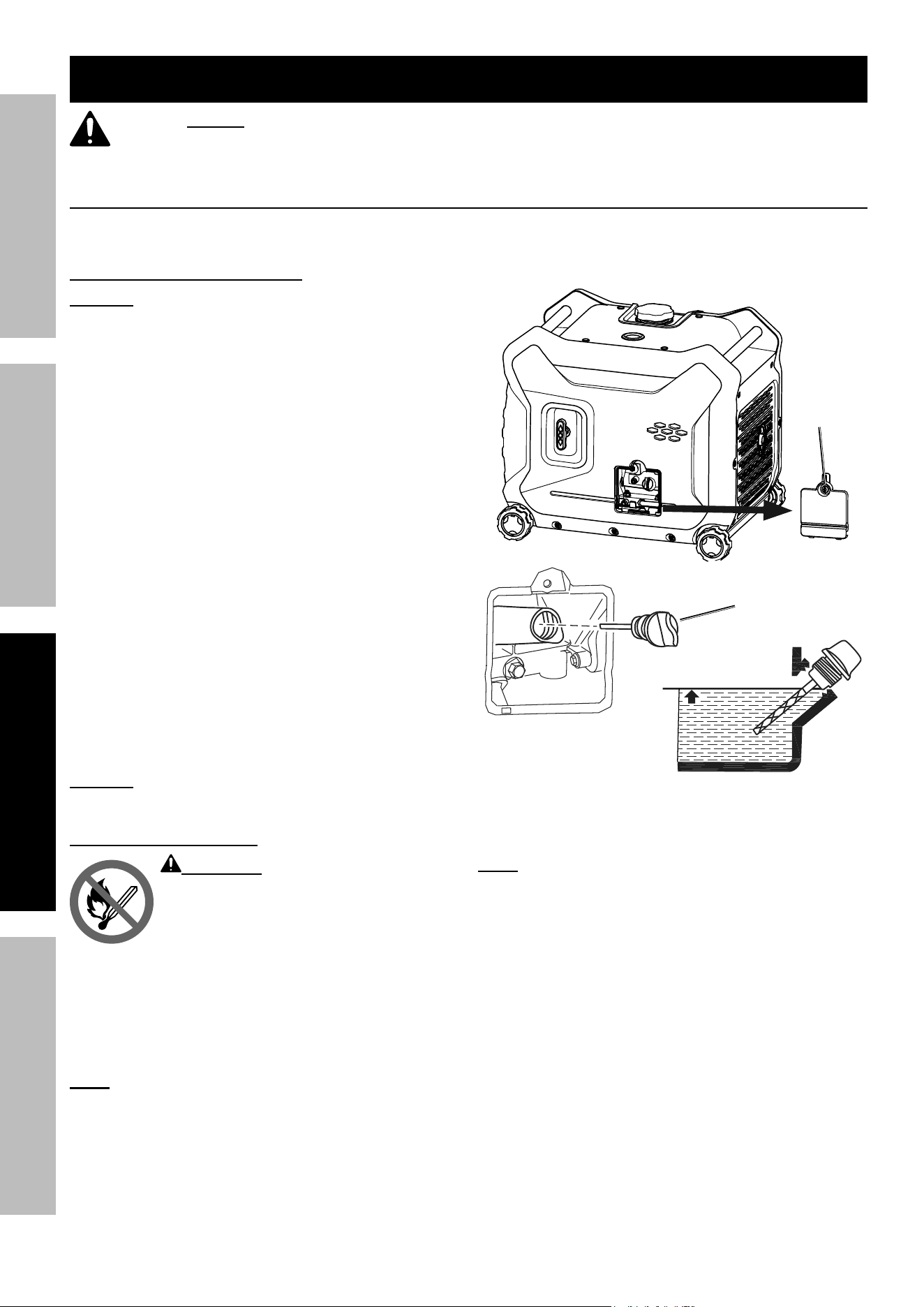
Draining the Carburetor
After closing the Fuel Valve, place an appropriate
container under the Carburetor and carefully
remove the Drain Bolt from the bottom of the
Carburetor Bowl, allowing the fuel to drain
completely. Replace the Drain Bolt after draining.
WarninG! To prevent serious
injury and fire, close the Fuel Valve
before draining the Carburetor.
3. LuBriCaTiOn:
a. Change engine oil.
b. Clean out area around spark plug.
Remove spark plug and pour one tablespoon of
engine oil into cylinder through spark plug hole.
c. Replace spark plug, but leave
spark plug cap disconnected.
d. Pull Starter Handle to distribute oil in cylinder.
Stop after one or two revolutions when you
feel the piston start the compression stroke
(when you start to feel resistance).
4. STOraGe area:
Cover and store in a dry, level, well-ventilated
area out of reach of children. Storage area should
also be away from ignition sources, such as
water heaters, clothes dryers, and furnaces.
nOTiCe: During extended storage periods the
Engine must be started every 3 months and allowed
to run for 15 – 20 minutes or the Warranty is VOID.
5. aFTer STOraGe:
Before starting the engine after storage, keep in
mind that untreated gasoline will deteriorate quickly.
Drain the fuel tank and change to fresh fuel if
untreated gasoline has been sitting for a month, if
treated gasoline has been sitting beyond the fuel
stabilizer’s recommended time period, or if the
engine does not start.

Page 23
For technical questions, please call 1-800-444-3353.
ITEM 71358
SaFeTyOperaTiOnMainTenanCe SeTup
Troubleshooting
problem possible Causes probable Solutions
Engine will not start FUEL RELATED:
1. No fuel in tank or fuel valve closed.
2. Choke not in START position, cold engine.
3. Gasoline with more than 10% ethanol
used. (E15, E20, E85, etc.)
4. Low quality or deteriorated, old gasoline.
5. Carburetor not primed.
6. Dirty fuel passageways.
7. Carburetor needle stuck.
Fuel can be smelled in the air.
8. Too much fuel in chamber. This can be
caused by the carburetor needle sticking.
9. Clogged Fuel Filter.
FUEL RELATED:
1. Fill fuel tank with fresh 87+ octane stabilizer-treated
unleaded gasoline and open fuel valve.
Do not use gasoline with more than
10% ethanol (e15, e20, e85, etc.).
2. Move Choke to START position.
3. Clean out ethanol rich gasoline from fuel system.
Replace components damaged by ethanol. Use fresh
87+ octane stabilizer-treated unleaded gasoline only.
Do not use gasoline with more than
10% ethanol (e15, e20, e85, etc.).
4. Use fresh 87+ octane stabilizer-treated
unleaded gasoline.
Do not use gasoline with more than
10% ethanol (e15, e20, e85, etc.).
5. Pull on Starter Handle to prime.
6. Clean out passageways using fuel additive.
Heavy deposits may require further cleaning.
7. Gently tap side of carburetor float
chamber with screwdriver handle.
8. Turn Choke to RUN position. Remove spark plug and
pull the start handle several times to air out the chamber.
Reinstall spark plug and set Choke to START position.
9. Replace Fuel Filter.
IGNITION (SPARK) RELATED:
1. Combination Switch at OFF position.
2. Spark plug cap not connected securely.
3. Spark plug electrode wet or dirty.
4. Incorrect spark plug gap.
5. Spark plug cap broken.
6. Circuit breaker tripped (electric
start models only).
7. Incorrect spark timing or
faulty ignition system.
IGNITION (SPARK) RELATED:
1. Turn Combination Switch to START.
2. Connect spark plug cap properly.
3. Clean spark plug.
4. Correct spark plug gap.
5. Replace spark plug cap.
6. Reset circuit breaker. Check wiring and
starter motor if breaker continues to trip.
7. Have qualified technician diagnose/
repair ignition system.
COMPRESSION RELATED:
1. Cylinder not lubricated.
Problem after long storage periods.
2. Loose or broken spark plug.
(Hissing noise will occur
when trying to start.)
3. Loose cylinder head or damaged
head gasket. (Hissing noise will
occur when trying to start.)
4. Engine valves or tappets
mis-adjusted or stuck.
ENGINE OIL RELATED:
1. Low engine oil.
2. Engine mounted on slope,
triggering low oil shutdown.
SPARK ARRESTOR RELATED:
1. Spark Arrestor clogged with soot.
COMPRESSION RELATED:
1. Pour tablespoon of oil into spark plug hole. Crank
engine a few times and try to start again.
2. Tighten spark plug.
If that does not work, replace spark plug.
If problem persists, may have head
gasket problem, see #3.
3. Tighten head.
If that does not remedy problem, replace head gasket.
4. Have qualified technician adjust/
repair valves and tappets.
ENGINE OIL RELATED:
1. Fill engine oil to proper level. Check engine
oil before EVERY use.
2. Operate engine on level surface. Check engine oil level.
SPARK ARRESTOR RELATED:
1. Clean and replace Spark Arrestor.
Follow all safety precautions whenever diagnosing or servicing the generator or engine.
Page 24
For technical questions, please call 1-800-444-3353.
ITEM 71358
SaFeTy OperaTiOn MainTenanCeSeTup
problem possible Causes probable Solutions
Engine will not
start (continued)
ELECTRIC START RELATED:
1. No battery or defective battery installed.
2. Battery is low.
3. Electric start fuse (5A) is blown.
ELECTRIC START RELATED:
1. Install a new battery (see page 8).
2. Charge the battery.
3. Replace fuse with similar size fuse.
Engine misfires 1. Spark plug cap loose.
2. Incorrect spark plug gap or
damaged spark plug.
3. Defective spark plug cap.
4. Old or low quality gasoline.
5. Incorrect compression.
1. Check cap and wire connections.
2. Re-gap or replace spark plug.
3. Replace spark plug cap.
4. Use only fresh 87+ octane stabilizer-treated
unleaded gasoline.
Do not use gasoline with more than
10% ethanol (e15, e20, e85, etc.).
5. Diagnose and repair compression. (Use engine will
not start: COMpreSSiOn reLaTeD section.)
Engine stops suddenly 1. Carbon Monoxide level high. Red light
on Carbon Monoxide Sensor illuminates.
2. CO Sensor Alarm flashes yellow
continually shortly after starting.
3. CO Sensor Alarm flashes yellow
continually after longer period of operation.
4. Low oil shutdown.
5. Fuel tank empty or full of impure or low
quality gasoline.
6. Defective fuel tank cap creating
vacuum, preventing proper fuel flow.
7. Faulty magneto.
8. Disconnected or improperly
connected spark plug cap.
1. Leave area immediately and allow area to ventilate
thoroughly. Only operate generator outside.
2. Carbon monoxide sensor malfunction.
Sensor needs service. Call 1-800-444-3353 as
soon as possible. Do not use the Generator
until the sensor is working properly.
3. Make sure to operate generator within rated
ambient temperature; maintain minimum
5 ft. clearance from all sides.
4. Fill engine oil to proper level. Check
engine oil before EVERY use.
5. Fill fuel tank with fresh 87+ octane stabilizer treated
unleaded gasoline.
Do not use gasoline with more than 10%
ethanol (E15, E20, E85, etc.).
6. Test/replace fuel tank cap.
7. Have qualified technician service magneto.
8. Secure spark plug cap.
Engine stops when
under heavy load
1. Dirty air filter
2. Engine running cold.
1. Clean element.
2. Allow engine to warm up prior to operating equipment.
Engine knocks 1. Old or low quality gasoline.
2. Engine overloaded.
3. Incorrect spark timing, deposit
buildup, worn engine, or other
mechanical problems.
1. Fill fuel tank with fresh 87+ octane stabilizer-treated
unleaded gasoline.
Do not use gasoline with more than
10% ethanol (e15, e20, e85, etc.).
2. Do not exceed equipment’s load rating.
3. Have qualified technician diagnose and service engine.
Engine backfires 1. Impure or low quality gasoline.
2. Engine too cold.
3. Intake valve stuck or overheated engine.
4. Incorrect timing.
1. Fill fuel tank with fresh 87+ octane stabilizer-treated
unleaded gasoline.
Do not use gasoline with more than
10% ethanol (e15, e20, e85, etc.).
2. Use cold weather fuel and oil additives
to prevent backfiring.
3. Have qualified technician diagnose and service engine.
4. Check engine timing.
Follow all safety precautions whenever diagnosing or servicing the generator or engine.
Page 25
For technical questions, please call 1-800-444-3353.
ITEM 71358
SaFeTyOperaTiOnMainTenanCe SeTup
problem possible Causes probable Solutions
Attached device
doesn’t have power
1. Device not plugged in properly.
2. Circuit Breaker tripped.
3. Product needs service.
1. Turn off and unplug the device,
then plug it back in again and turn on.
2. Turn off and unplug device, reset Circuit
Breaker, plug in device and turn on.
3. Have product repaired.
Attached device
begins to operate
abnormally
1. Problem with device.
2. Rated load capacity exceeded.
1. Immediately unplug device.
Have device repaired by a qualified
technician, or replace device.
2. Lower the number of items plugged into the
generator to stay within the rated capacity,
or use a more powerful generator.
Follow all safety precautions whenever diagnosing or servicing the generator or engine.
pLeaSe reaD THe FOLLOWinG CareFuLLy
THE MANUFACTURER AND/OR DISTRIBUTOR HAS PROVIDED THE PARTS LISTS AND ASSEMBLY
DIAGRAMS IN THIS MANUAL AS A REFERENCE TOOL ONLY. NEITHER THE MANUFACTURER OR
DISTRIBUTOR MAKES ANY REPRESENTATION OR WARRANTY OF ANY KIND TO THE BUYER THAT HE
OR SHE IS QUALIFIED TO MAKE ANY REPAIRS TO THE PRODUCT, OR THAT HE OR SHE IS QUALIFIED
TO REPLACE ANY PARTS OF THE PRODUCT. IN FACT, THE MANUFACTURER AND/OR DISTRIBUTOR
EXPRESSLY STATES THAT ALL REPAIRS AND PARTS REPLACEMENTS SHOULD BE UNDERTAKEN BY
CERTIFIED AND LICENSED TECHNICIANS, AND NOT BY THE BUYER. THE BUYER ASSUMES ALL RISK
AND LIABILITY ARISING OUT OF HIS OR HER REPAIRS TO THE ORIGINAL PRODUCT OR REPLACEMENT
PARTS THERETO, OR ARISING OUT OF HIS OR HER INSTALLATION OF REPLACEMENT PARTS THERETO.
Troubleshooting (continued)
record product’s Serial number Here:
note: If product has no serial number, record month and year of purchase instead.
note: Some parts are listed and shown for illustration purposes only, and are not available
individually as replacement parts. Specify UPC 193175456229 when ordering parts.
Page 26
For technical questions, please call 1-800-444-3353.
ITEM 71358
SaFeTy OperaTiOn MainTenanCeSeTup
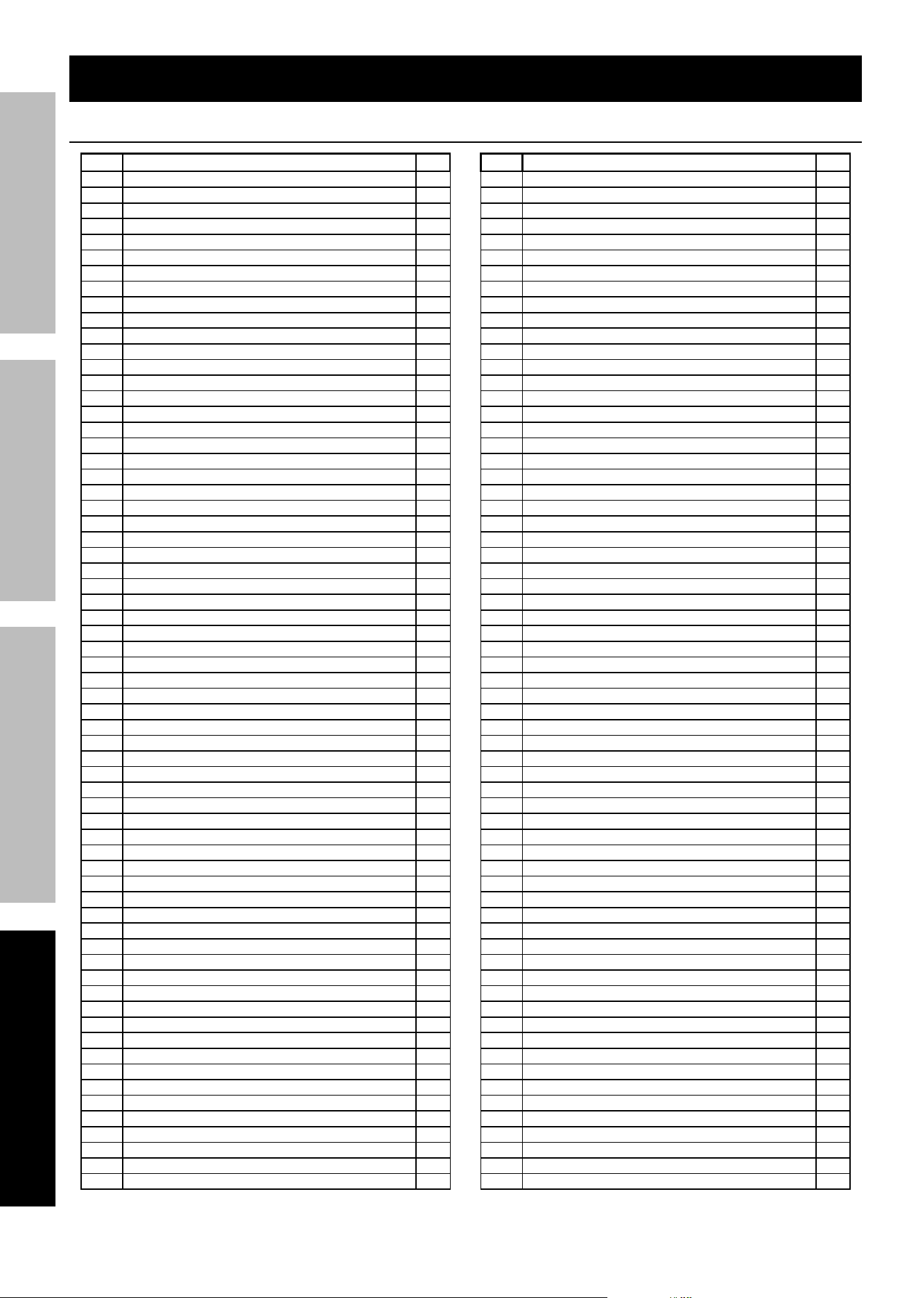
part Description Qty
1 Gasket, Crankcase 1
2 Tube, Oil Drain 1
3 Crankcase Subassembly. 1
4 Stop Engine Piece Subassembly 1
5 Gasket, Breath Groove 1
6 Cover, Crankcase 1
7 Cylinder Head Bolt 4
8 Cylinder Head Cover Gasket 1
9 Guide, Seal 1
10 Spring, Valve 2
11 Clamp, Valve Lock 4
12 Valves Set 1
13 Seat, Valve Spring 2
14 Gasket, Cylinder Head 1
15 Head Subassembly, Cylinder 1
16 Cover Subassembly, Cylinder Head 1
17 Cylinder Head Cover Pin Limit Plate 1
18 Rod, Connecting 1
19 Piston 1
20 Pin, Piston 1
21 Clip, Piston Pin 2
22 Ring Assy, Piston 1
23 Crankshaft Assy. 1
24 Nut, Flywheel 1
25 Lifter, Valve 2
26 Tappet, Valve 2
27 Camshaft Assy. 1
28 Rocker Subassembly, Valve 2
29 Shaft Subassembly, Rocker 2
30 Dipstick Subassembly, Oil 1
31 Shield Cover 1
32 Carburetor Seal Gasket 1
33 Gasket, Carburetor Insulator 1
34 Plate, Carburetor Insulator 1
35 Carburetor Assy. 1
36 Strainer, Fuel 1
37 Air Cleaner Seal Gasket 1
38 Tube, Breather 1
39 Secondary Air Filter 1
40 Gasket, Exhaust Outlet 2
41 Bracket,Muffler 1
42 Muffler Assy. 1
43 Installation Support, Muffler Outer Cover 1
44 Shield, Crankcase Side 1
45 Impeller 1
46 Impeller 1
47 Pulley,Starter 1
48 Seat, Starter Cup 1
49 Starter, Recoil 1
50 Shroud 1
51 Clamp, Magneto Wiring 1
52 Plug, Spark 1
53 Case Subassembly, Magneto Rotor 1
54 Stator Subassembly, Magneto 1
55 Trigger Assy. 1
56 Motor Assy,Starting 1
57 Coil, Ignition 1
58 Jacket, Rubber 1
59 Wire, Anode 1
60 Wire, Cathode 1
61 Sensor, Engine Oil 1
62 Bolt 2
63 Bolt 2
64 Bolt 13
65 Bolt 5
part Description Qty
66 Bolt 4
67 Bolt 4
68 Bolt 5
69 Bolt 1
70 Bolt 6
71 Bolt 2
72 Bolt 1
73 Screw 3
74 Screw, Cross Groove Pan 1
75 Bolt 2
76 Bolt 2
77 Nut 2
78 Nut 2
79 Nut 1
80 Washer, Flat 3
81 Washer, Flat 1
82 Pin 4
83 Pin 2
84 Bearing, Deep Groove Ball 1
85 Bearing, Deep Groove Ball 1
86 Seal, Oil 2
87 Clip 3
88 Clamp 1
89 Tube, Fuel 1
90 Joint, Fuel Tube 1
91 Bolt 2
92 Hoop 2
93 Tube, Intake 1
94 Air Cleaner 1
95 Screw 2
96 Left Housing Cover Plate 1
97 Bolt 15
98 Left Housing 1
99 Sleeve, Fuel Tank Rubber 4
100 Hex Step Bolt 6
101 Clip Nut 15
102 Crosspiece, Back 1
103 Bolt 4
104 Fuel Steam Collector Mounting Plate 1
105 Collector, Fuel Steam 1
106 Jacket, Rubber 1
107 Hose, Fuel Steam Rubber 1
108 Hose, Air Cleaner Rubber 1
109 Hose, Fuel Steam Rubber 1
110 Jacket, Rubber 2
111 Pipe Clamp 2
112 Pipe Clamp 2
113 Frame Assy, Engine 1
114 Frame Assy, Engine 1
115 Nut With Flange 18
116 Self-Tapping Screw 8
117 Handle 2
118 Case, Battery 1
119 Battery 1
120 Bolt 2
121 Plate, Right Bottom 1
122 Invertor 1
123 Jacket, Rubber 3
124 Bush 3
125 Bolt 7
126 Grounding 1
127 Flat Washer 1
128 Cross-Recessed Pan Head Screw 1
129 Seat, Panel 1
130 Hex Step Bolt 15
parts List and Diagram
parts List

Page 27
For technical questions, please call 1-800-444-3353.
ITEM 71358
SaFeTyOperaTiOnMainTenanCe SeTup
part Description Qty
131 Nylon Nut 2
132 Stopper 2
133 Battery Cover 1
134 Hex Step Bolt 2
135 Panel Subassembly, Control 1
136 Cross-Recessed Small Pan Head Screw,
Spring Washer And Flat Washer Assembly
6
137 Knob 1
138 Cross-Recessed Pan Head Screw 1
139 Cross-Recessed Countersunk Head
Tapping Screw
3
140 Switch Subassembly 1
141 Ball, Steel 1
142 Spring, Stopper Adjusting 1
143 Cover Plate 1
144 Cock Assy, Fuel 1
145 Pipe Clamp 2
146 Pipe Clamp 1
147 Deflector, Crankcase Air 1
148 Dynamic Left Support 1
149 Dynamic Right Support 1
150 Cushion, Engine Frame Left 2
151 Cushion, Engine Frame Right 2
152 Support, Atr Cleaner 1
153 Buffering Pad Support 1
154 Plug, End 1
155 Plate, Bottom 1
156 Square Nut 6
157 Flat Washer - Grade A 2
158 Nut With Flange 2
159 Bolt 4
160 Bottom Plate Reinforcement Plate 1
161 Tray, Lock 1
162 Wheel, Front 4
163 Flat Washer 4
164 Cotter Pin 4
165 Cover, Hub Decorated 4
166 Handle Sub, Lock 1
167 Cap 1
168 Bracket Fixing Plate 1
169 Guide, Starting Rope 1
170 Crosspiece 1
171 Right Housing 1
172 Right Appearance Cover Plate 1
173 Self-Tapping Screw 6
174 Spring Clamp 5
part Description Qty
175 Buffering Pad Support 1
176 Right Access Door 1
177 Handle, Recoil Strater Cable 1
178 Fuel Tank 1
179 Flat Washer - Grade A 4
180 Bush 4
181 Sleeve, Fuel Tank Rubber 4
182 Outlet Subassembly, Fuel Tank Oil 1
183 Leveler Assy, Oil 1
184 Cover, Upper 1
185 Plug, End 4
186 Opening, Oil Leverler View 1
187 Jacket, Rubber 1
188 Sleeve, Filling Oil Hole Rubber 1
189 Strainer, Fuel 1
190 Chain Proof Off, Fuel Tank Cover 1
191 Cover, Fuel Tank 1
192 Handle Subassembly, Choke 1
193 Tube, Fuel 1
194 Engine 1
195 Muffler Outer Cover 1
196 Hex Step Bolt 6
197 Muffler Insulator Rubber 2 1
198 Cover, Muffler Side 1
199 Clip Nut 1
200 Co Sensor 1
201 Hexalobular Socket Central Stud Pan
Head Screw
2
202 Anti-Off Chain Clip 1
203 Bolt 2
204 Socket Subassembly, Power Supply 1
205 Socket Subassembly, Power Supply 1
206 Socket Subassembly, Power Supply 1
207 Protector, Overcurrent 1
208 Socket Subassembly, Power Supply 1
209 Timer 1
210 Bridge, Rectification 1
211 Co Controller 1
212 Switch Subassembly 1
213 Switch Subassembly 1
214 Charger Module 1
215 Indicator 1
216 Protector, Overcurrent 1
217 Socket Subassembly, D.C 1
218 Protector, Overcurrent 1
219 Terminal Subassembly, Grounding 1
parts List (continued)
Page 28
For technical questions, please call 1-800-444-3353.
ITEM 71358
SaFeTy OperaTiOn MainTenanCeSeTup
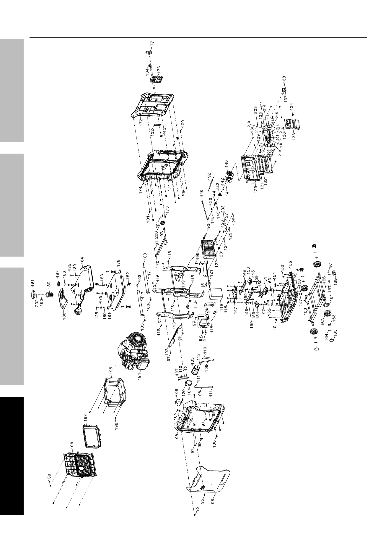
assembly Diagram

Page 29
For technical questions, please call 1-800-444-3353.
ITEM 71358
SaFeTyOperaTiOnMainTenanCe SeTup
Warranties
Limited 90 Day Warranty (retail)
Harbor Freight Tools Co. makes every effort to assure that its products meet high quality and durability standards,
and warrants to the original purchaser that this product is free from defects in materials and workmanship for the
period of 90 days from the date of purchase. This warranty does not apply to damage due directly or indirectly,
to misuse, abuse, negligence or accidents, repairs or alterations outside our facilities, criminal activity, improper
installation, normal wear and tear, or to lack of maintenance. We shall in no event be liable for death, injuries
to persons or property, or for incidental, contingent, special or consequential damages arising from the use of
our product. Some states do not allow the exclusion or limitation of incidental or consequential damages, so
the above limitation of exclusion may not apply to you. THIS WARRANTY IS EXPRESSLY IN LIEU OF ALL
OTHER WARRANTIES, EXPRESS OR IMPLIED, INCLUDING THE WARRANTIES OF MERCHANTABILITY
AND FITNESS, EXCEPT FOR THE EMISSIONS CONTROL SYSTEM WARRANTY BELOW.
To take advantage of this warranty, the product or part must be returned to us with transportation charges prepaid.
Proof of purchase date and an explanation of the complaint must accompany the merchandise. If our
inspection verifies the defect, we will either repair or replace the product at our election or we may elect to
refund the purchase price if we cannot readily and quickly provide you with a replacement. We will return
repaired products at our expense, but if we determine there is no defect, or that the defect resulted from
causes not within the scope of our warranty, then you must bear the cost of returning the product.
This warranty gives you specific legal rights and you may also have other rights which vary
from state to state. HFT also warrants that the emissions control system on your engine is
designed, built, and equipped so that it conforms to the United States Environmental Protection
Agency’s (EPA) emissions requirements in effect at the time of manufacture.
emissions Control System Warranty
The California Air Resources Board, the United States Environmental Protection Agency, and
Harbor Freight Tools (HFT) are pleased to explain the exhaust and evaporative emissions (“emissions”) control
system warranty on your [Model Year] Small Off-Road Engine, in addition to the Retail Warranty above. In California,
new equipment that uses small off-road engines must be designed, built, and equipped to meet the State’s stringent
anti-smog standards. HFT must warrant that the emissions control system on your small off-road engine will be free
from defects in material and workmanship for the period listed below, provided there has been no abuse, neglect,
or improper maintenance of your small off-road engine leading to the failure of the emissions control system.
Your emissions control system may include parts such as the carburetor or fuel-injection
system, the ignition system, catalytic converter, fuel tanks, fuel lines (for liquid fuel and fuel
vapors), fuel caps, valves, canisters, filters, clamps, and other associated components.
Also included may be hoses, belts, connectors, and other emissions-related assemblies.
Where a warrantable condition exists, HFT will repair or replace, at our option,
your engine if at no cost to you, including diagnosis, parts and labor.
ManuFaCTurer’S WarranTy COVeraGe
The exhaust and evaporative emissions control system on your small off-road engine is warranted for two years.
If any emission-related part on your small off-road engine is defective, the part will be repaired or replaced by HFT.
OWner’S WarranTy reSpOnSiBiLiTieS
As the small off-road engine owner, you are responsible for the performance of the required
maintenance listed in your Owner’s Manual. HFT recommends that you retain all receipts covering
maintenance on your small off-road engine, but HFT cannot deny warranty coverage solely for the
lack of receipts or for your failure to ensure the performance of all scheduled maintenance.
As the small off-road engine owner, you should however be aware that HFT may deny you warranty
coverage if your small off-road engine or a part has failed due to abuse (including failure to follow the fuel use
instructions contained in this manual), neglect, or improper maintenance or unapproved modifications.
You are responsible for contacting HFT as soon as the problem exists in order to obtain warranty
repair or replacement, by doing either of the following: (a) contact HFT product support at 1-800-444-3353
or [email protected]; or (b) bring the to your nearest Harbor Freight Tools retail store.
The nearest Harbor Freight Tools retail store can be found on the internet at https://www.harborfreight.com.
The warranty repairs or replacement should be completed in a reasonable amount of time, not to
exceed 30 days. If you have a question regarding your warranty coverage, you should contact
HFT product support at 1-800-444-3353 or [email protected].

Page 30
For technical questions, please call 1-800-444-3353.
ITEM 71358
SaFeTy OperaTiOn MainTenanCeSeTup
DeFeCTS WarranTy reQuireMenTS:
a) The warranty period begins on the date the engine or equipment is delivered
to an ultimate purchaser. The warranty period is two years.
b) HFT warrants to the ultimate owner and each subsequent owner that the engine or equipment is:
1. Designed, built, and equipped so as to conform with all applicable
regulations adopted by the Air Resources Board; and
2. Free from defects in materials and workmanship that causes the
failure of a warranted part for a period of two years.
c) The warranty on emissions-related parts is as follows:
1. Any warranted part that is not scheduled for replacement as required maintenance in the written
instructions must be warranted for the warranty period stated above. If any such part fails during the
period of warranty coverage, it will be repaired or replaced HFT according to Subsection (4) below. Any
such part repaired or replaced under the warranty must be warranted for the remaining warranty period.
2. Any warranted part that is scheduled only for regular inspection in the written instructions
must be warranted for the warranty period defined in Subsection (b)(2). A statement in such
written instructions to the effect of “repair or replace as necessary” shall advise owners of
the warranty coverage for emissions related parts. Replacement within the warranty period is
covered by the warranty and will not reduce the period of warranty coverage. Any such part
repaired or replaced under warranty must be warranted for the remaining warranty period.
3. Any warranted part that is scheduled for replacement as required maintenance in the written
instructions must be warranted for the period of time prior to the first scheduled replacement point
for that part. If the part fails prior to the first scheduled replacement, the part must be repaired
or replaced by HFT. Any such part repaired or replaced under warranty must be warranted for
the remainder of the period prior to the first scheduled replacement point for the part.
4. Repair or replacement of any warranted part under the warranty provisions must be performed at
no charge to the owner at a retail store or by HFT paying for shipping the product for repair.
5. Notwithstanding the provisions herein, warranty services or repairs must be provided at
all retail stores that are franchised to service the subject engine or by contacting HFT
product support at 1-800-444-3353 or [email protected].
6. The owner must not be charged for diagnostic labor that leads to the determination that a warranted
part is in fact defective, provided that such diagnostic work is performed at a retail store.
7. HFT is liable for damages to other engine components proximately
caused by a failure under warranty of any warranted part.
8. Throughout the emissions control system’s warranty period stated above, HFT must
maintain a supply of warranted parts sufficient to meet the expected demand for
such parts and must obtain additional parts if that supply is exhausted.
9. Manufacturer-approved replacement parts that do not increase the exhaust or evaporative emissions of the
engine or emissions control system must be used in the performance of any warranty maintenance or repairs
and must be provided without charge to the owner. Such use will not reduce the warranty obligations of HFT.
10. Add-on or modified parts that are not exempted by the Air Resources Board may not be used. The use of
any non-exempted add-on or modified parts may be grounds for disallowing a warranty claim. HFT will not be
liable to warrant failures of warranted parts caused by the use of a non-exempted add-on or modified part.
11. HFT issuing the warranty shall provide any documents that describe that warranty
procedures or policies within five working days of request by the Executive Officer.

Page 31
For technical questions, please call 1-800-444-3353.
ITEM 71358
SaFeTyOperaTiOnMainTenanCe SeTup
d) Emission Warranty Parts List.
1. Fuel Metering System
a. Carburetor and its internal parts (and/or pressure
regulator or fuel injection system).
b. Air/fuel ratio feedback and control system.
c. Cold start enrichment system.
2. Air Induction System
a. Controlled hot air intake system.
b. Intake manifold.
c. Air filter.
3. Ignition System
a. Spark plugs.
b. Magneto ignition system.
c. Spark advance/retard system.
4. Exhaust Gas Recirculation (EGR) System
a. EGR valve body, and carburetor spacer if
applicable.
b. EGR rate feedback and control system.
5. Air Injection System
a. Air pump or pulse valve.
b. Valves affecting distribution of flow.
c. Distribution manifold.
6. Catalyst or Thermal Reactor System
a. Catalytic converter.
b. Thermal reactor.
c. Exhaust manifold.
7. Particulate Controls
a. Traps, filters, precipitators, and any other device
used to capture particulate emissions.
8. Miscellaneous Items Used in Above Systems
a. Electronic controls.
b. Vacuum, temperature, and time sensitive valves
and switches.
c. Hoses, belts, connectors, and assemblies.
e) Emission Warranty Parts List for Evap
1. Fuel Tank
2. Fuel Cap
3. Fuel Lines (for liquid fuel and fuel vapors)
4. Fuel Line Fittings
5. Clamps*
6. Pressure Relief Valves*
7. Control Valves*
8. Control Solenoids*
9. Electronic Controls*
10. Vacuum Control Diaphragms*
11. Control Cables*
12. Control Linkages*
13. Purge Valves*
14. Gaskets*
15. Liquid/Vapor Separator
16. Carbon Canister
17. Canister Mounting Brackets
18. Carburetor Purge Port Connector
*Note: As they relate to the evaporative emission control system.
HFT will furnish with each new small off-road engine/equipment written instructions for the maintenance and use
of the engine/equipment by the owner.

26677 agoura road • Calabasas, Ca 91302 • 1-800-444-3353