OPERATION AND INSTALLATION
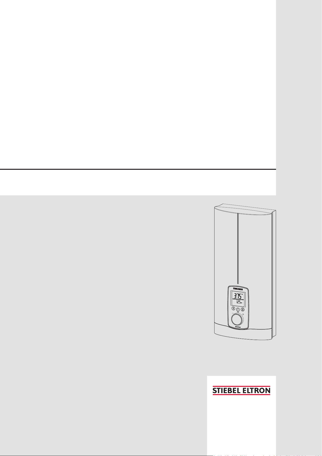
Fully electronically controlled comfort instantaneous water heater
» DHE 18 AU
» DHE 27 AU

2 | DHE AU www.stiebel-eltron.com
CONTENTS
SPECIAL INFORMATION
OPERATION
1. General information �����������������������������������������4
1.1 Safety instructions ����������������������������������������������� 4
1.2 Other symbols in this documentation ����������������������� 4
1.3 Units of measurement ������������������������������������������ 4
2. Safety ���������������������������������������������������������� 4
2.1 Intended use ������������������������������������������������������ 4
2.2 General safety instructions ������������������������������������ 4
2.3 Test symbols ������������������������������������������������������ 5
3. Appliance description ���������������������������������������5
4. Settings and displays ����������������������������������������5
4.1 User interface ���������������������������������������������������� 5
4.2 Display symbols �������������������������������������������������� 6
4.3 Selecting the set temperature ��������������������������������� 6
4.4 Temperature limit via internal anti-scalding
protection (qualified contractor)������������������������������ 6
4.5 Temperature limit Tmax (user) �������������������������������� 6
4.6 Assigning temperature memory buttons ������������������� 6
4.7 Inlet temperature information �������������������������������� 6
4.8 Info menu ��������������������������������������������������������� 6
4.9 Settings in the parameter menu ������������������������������ 6
4.10 Recommended settings ���������������������������������������� 8
5. Cleaning, care and maintenance ���������������������������8
6. Troubleshooting ����������������������������������������������9
INSTALLATION
7. Safety ���������������������������������������������������������� 9
7.1 General safety instructions ������������������������������������ 9
7.2 Shower operation������������������������������������������������ 9
7.3 Instructions, standards and regulations �������������������� 9
8. Appliance description ������������������������������������� 10
8.1 Standard delivery ����������������������������������������������� 10
8.2 Accessories ������������������������������������������������������� 10
9. Preparation ������������������������������������������������� 10
9.1 Installation site �������������������������������������������������� 10
9.2 Minimum clearances ������������������������������������������� 10
9.3 Water installation ����������������������������������������������� 10
10. Installation �������������������������������������������������� 11
10.1 Standard installation ������������������������������������������� 11
11. Commissioning ��������������������������������������������� 13
11.1 Preparation ������������������������������������������������������ 13
11.2 Initial start-up ��������������������������������������������������� 13
11.3 Recommissioning ����������������������������������������������� 14
12. Appliance shutdown ��������������������������������������� 14
13. Installation alternatives ����������������������������������� 14
13.1 Electrical connection from above on unfinished walls �� 14
13.2 Electrical connection on unfinished walls from below
with short power cable ���������������������������������������� 15
13.3 Electrical connection on finished walls �������������������� 15
13.4 Water installation on unfinished walls ��������������������� 15
13.5 Wall mounting bracket when replacing an appliance ��� 16
13.6 Installation with offset tiles ����������������������������������� 16
13.7 Rotated appliance cover ��������������������������������������� 16
13.8 Operation with preheated water ���������������������������� 16
13.9 Horizontal installation of the appliance �������������������� 17
14. Service information ���������������������������������������� 17
15. Troubleshooting �������������������������������������������� 18
15.1 Fault code display ���������������������������������������������� 18
16. Maintenance ������������������������������������������������ 19
17. Specification ������������������������������������������������ 19
17.1 Dimensions and connections ��������������������������������� 19
17.2 Wiring diagram ������������������������������������������������� 20
17.3 DHW output ������������������������������������������������������ 20
17.4 Application areas/ conversion table ����������������������� 20
17.5 Pressure drop ��������������������������������������������������� 20
17.6 Fault conditions ������������������������������������������������� 20
17.7 Data table �������������������������������������������������������� 21
SOFTWARE COPYRIGHT
ENVIRONMENT AND RECYCLING
WARRANTY

SpECiAl iNfOrmATiON
www.stiebel-eltron.com DHE AU | 3
SpECiAl iNfOrmATiON
- The appliance may be used by children over
3years of age and persons with reduced
physical, sensory or mental capabilities or a
lack of experience and expertise, provided
that they are supervised or they have been
instructed on how to use the appliance safe-
ly and have understood the potential risks.
Children must never play with the appliance.
Cleaning and user maintenance must not be
carried out by children without supervision.
- If using preheated water, the fitting can reach
a temperature of up to 70°C during opera-
tion. There is a risk of scalding at outlet tem-
peratures in excess of 43°C.
- The appliance is suitable for supplying a
shower (shower operation). If the appliance
is also or exclusively used for shower opera-
tion, the qualified contractor must adjust the
temperature setting range to 43°C using the
internal anti-scalding protection on the ap-
pliance. When using preheated water, ensure
that the inlet temperature does not exceed
55°C.
- In Australia, the use of a temperature control-
ler is required to meet the requirements of
AS3498 when showers, bathtubs or washba-
sins are supplied with water. The maximum
temperature of 50°C must not be exceeded.
- Ensure the appliance can be separated from
the power supply by an isolator that discon-
nects all poles with at least 3mm contact
separation.
- The specified voltage must match the power
supply.
- The appliance must be connected to the earth
conductor.
- The appliance must be permanently connect-
ed to fixed wiring.
- Secure the appliance as described in chapter
"Installation/ Installation".
- Observe the maximum permissible pressure
(see chapter "Installation/ Specification/ Data
table").
- The specific water resistivity of the mains
water supply must not be undershot (see
chapter "Installation/ Specification/ Data
table").
- Drain the appliance as described in chapter
"Installation/ Maintenance/ Draining the
appliance".
OpErATiON
General information
4 | DHE AU www.stiebel-eltron.com
OpErATiON
1. General information
The chapters "Special information" and "Operation" are intended
for both users and qualified contractors.
The chapter "Installation" is intended for qualified contractors.
Note
Read these instructions carefully before using the appli-
ance and retain them for future reference.
Pass on these instructions to a new user if required.
1.1 Safety instructions
1.1.1 Structure of safety instructions
!
KEYWORD Type of risk
Here, possible consequences are listed that may result
from failure to observe the safety instructions.
f Steps to prevent the risk are listed.
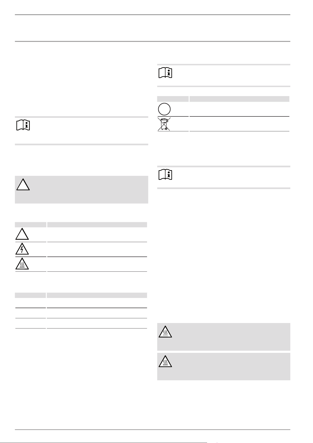
1.1.2 Symbols, type of risk
Symbol Type of risk
Injury
Electrocution
Burns
(burns, scalding)
1.1.3 Keywords
KEYWOrD meaning
DANGER Failure to observe this information will result in serious
injury or death.
WARNING Failure to observe this information may result in serious
injury or death.
CAUTION Failure to observe this information may result in non-seri-
ous or minor injury.
1.2 Other symbols in this documentation
Note
General information is identified by the adjacent symbol.
f Read these texts carefully.
Symbol meaning
Material losses
(appliance damage, consequential losses and environmen-
tal pollution)
Appliance disposal
f This symbol indicates that you have to do something. The ac-
tion you need to take is described step by step.
1.3 Units of measurement
Note
All measurements are given in mm unless otherwise
stated.
2. Safety
2.1 Intended use
This appliance is suitable for heating domestic hot water or for
reheating preheated water. The appliance can supply one or more
draw-off points.
Water will not be reheated if the maximum inlet temperature for
reheating is exceeded.
The appliance is intended for domestic use. It can be used safely
by untrained persons. The appliance can also be used in non-do-
mestic environments, e.g. in small businesses, as long as it is
used in the same way.
Any other use beyond that described shall be deemed inappro-
priate. Observation of these instructions and of the instructions
for any accessories used is also part of the correct use of this
appliance.
2.2 General safety instructions
CAUTION Burns
If using preheated water, the fitting can reach a temper-
ature of up to 70°C during operation. There is a risk of
scalding at outlet temperatures in excess of 43°C.
CAUTION Burns
If operating with preheated water, e.g.from a solar ther-
mal system, the DHW temperature may vary from the
selected set temperature.
!
!
OpErATiON
Appliance description
www.stiebel-eltron.com DHE AU | 5
CAUTION Burns
If children or persons with limited physical, sensory or
mental capabilities use the appliance, set a temperature
limit. Once set, check the temperature limit is working
correctly.
If a permanent and unchangeable temperature limit is
required, have the internal anti-scalding protection set
by a qualified contractor.
!
WARNING Injury
The appliance may be used by children over 3years of
age and persons with reduced physical, sensory or men-
tal capabilities or a lack of experience and expertise,
provided that they are supervised or they have been
instructed on how to use the appliance safely and have
understood the potential risks. Children must never play
with the appliance. Cleaning and user maintenance must
not be carried out by children without supervision.
!
WARNING
For continued safety of this appliance it must be in-
stalled, operated and maintained in accordance with
the manufacturer’s instructions.
!
WARNING
This appliance may deliver water at high temperature.
Refer to the plumbing code of Australia (PCA), local re-
quirements and installation instructions to determine
if additional delivery temperature control is required.
!
Material losses
The user should protect the appliance and its tap against
frost.
2.3 Test symbols
See type plate on the appliance.
3. Appliance description
The appliance switches on automatically as soon as you open the
hot water valve on the tap. When you close the tap, the appliance
switches off again automatically.
The appliance heats water as it flows through it. The set tempera-
ture is adjustable. Upwards of a certain flow rate, the control unit
selects the required heating output, subject to the temperature
selected and the cold water temperature.
The instantaneous water heater with full electronic control and
automatic output matching maintains a consistent outlet tempera-
ture. The fully electronic control unit with motorised valve ensures
the water is accurately heated to the selected temperature. This
occurs regardless of the inlet temperature.
If the appliance is operated with preheated water and the inlet
temperature exceeds the selected temperature, the inlet tempera-
ture is indicated on the second display line and flashes. The water
is not heated further.
You can store different set temperatures and call them up quickly.
In the ECO function, the integral motorised valve limits the flow
rate to 3preset levels. The appliance has setting options for a
temperature limit (Tmax function, user) and internal anti-scald-
ing protection (qualified contractor). The backlight switches on
automatically as soon as water starts to flow through the appli-
ance or you make a change on the user interface. The backlight
switches off automatically after water stops flowing or if no action
is performed.
Heating system
The bare wire heating system is enclosed within a pressure-tested
plastic jacket. The heating system with its stainless steel heater
spiral is suitable for hard and soft water areas and is largely in-
susceptible to scale build-up. The heating system ensures rapid
and efficient DHW provision.
Note
The appliance is equipped with an air detector that large-
ly prevents damage to the heating system. If, during op-
eration, air is drawn into the appliance, the appliance
shuts down heating output for one minute to protect the
heating system.
4. Settings and displays
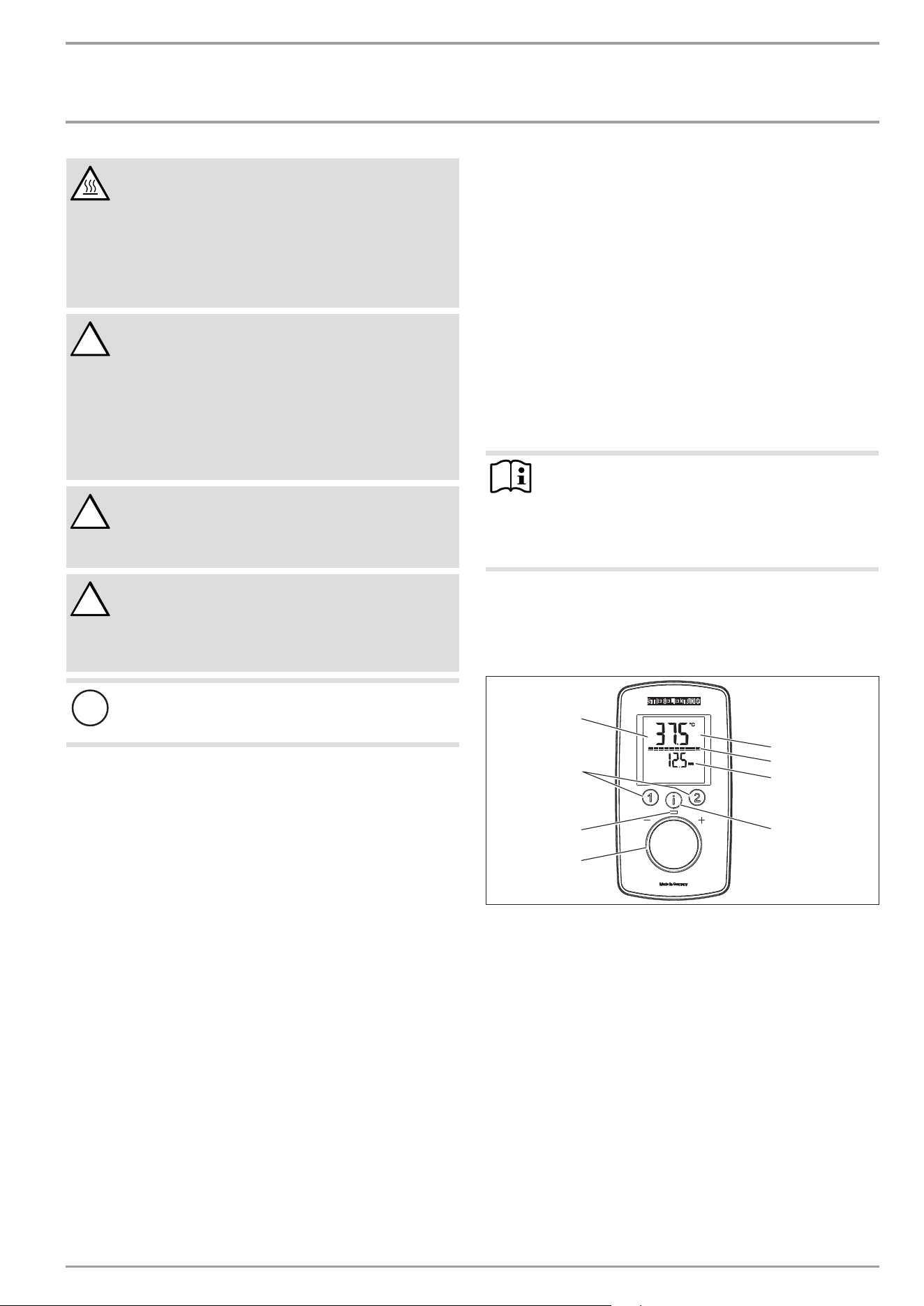
4.1 User interface
D0000091079
2
3
1
8
5
6
7
4
1 Selector
2 ON LED
3 Temperature memory keys
4 Backlit display
5 Main display | info display | parameter display
6 Segment display [10 - 100%]
7 Second display line
8 "i" button to call up information and select menus
OpErATiON
Settings and displays
6 | DHE AU www.stiebel-eltron.com
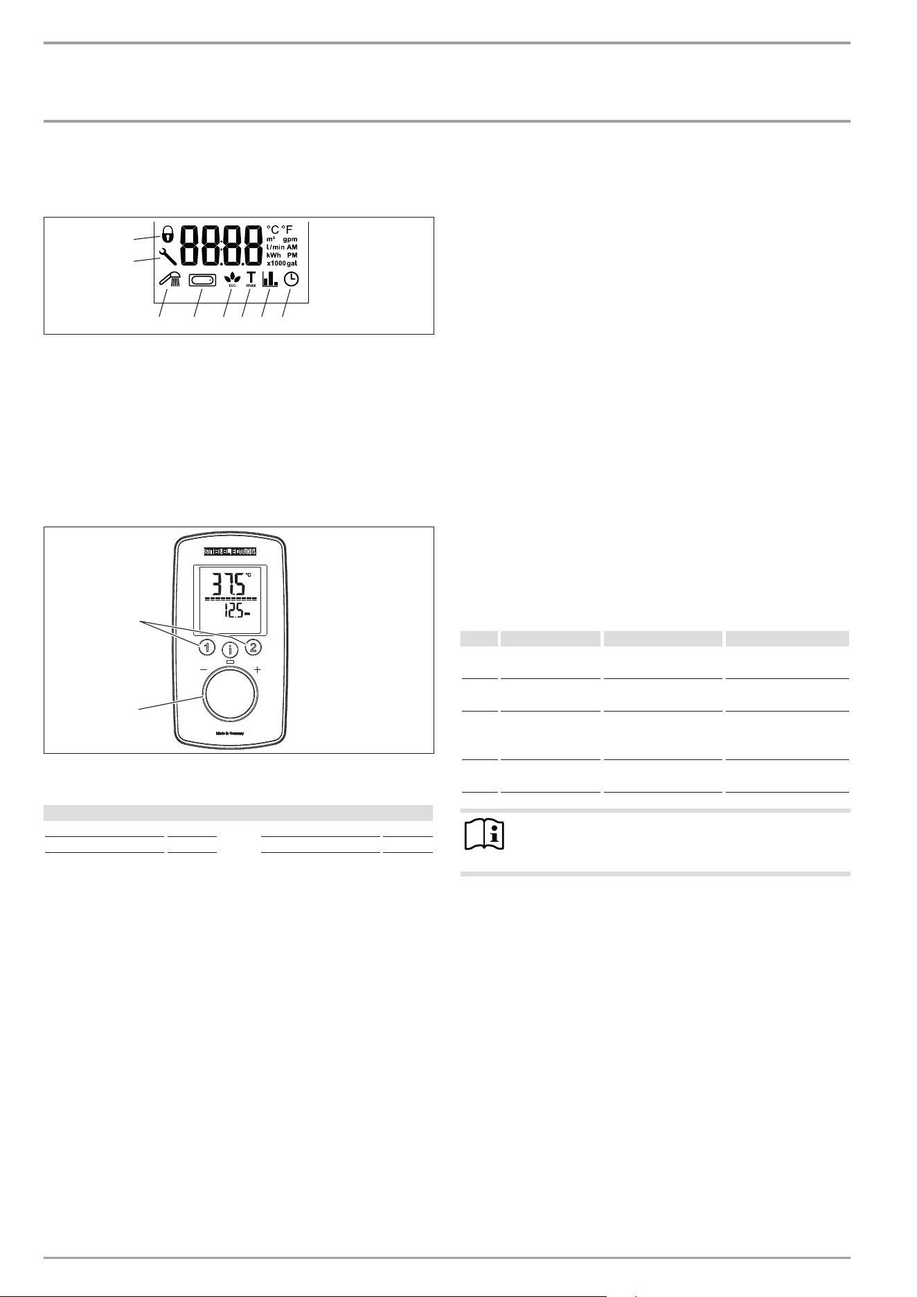
4.2 Display symbols
The symbols are shown on the display when activated.
7
8
1 2 6543
D0000073618
1 Wellness showers
2 Automatic water volume control
3 ECO display
4 Tmax, displayed when temperature limit is enabled
5 Consumption indicator
6 Time
7 Operating lock [ON/ OFF]
8 Spanner symbol, appears in the event of a fault
4.3 Selecting the set temperature
D0000091079
2
1
1 Set temperature settings: OFF, 20 - 60°C
2 To call up/assign preferred temperatures
Settings
Setting Step Setting Step
20°C ... 60°C 0.5°C 68°F ... 140°F 1°F
4.4 Temperature limit via internal anti-scalding
protection (qualified contractor)
If required, the qualified contractor can set a permanent temper-
ature limit, for example in nurseries, hospitals,etc.
If the anti-scalding protection function is enabled and the tem-
perature limit is reached, "Tmax" flashes.
4.5 Temperature limit Tmax (user)
You can adjust the temperature limit individually. If the tempera-
ture limit is enabled, "Tmax" is shown on the display.
4.5.1 Activating/deactivating the temperature limit Tmax
See chapter "Settings in the parameter menu".
4.6 Assigning temperature memory buttons
Memory buttons "1" and "2" can each be assigned a preferred
temperature.
f Select the preferred temperature.
f To save the preferred temperature, press and hold button
"1" or "2" for more than 3seconds. The selected temperature
flashes once to confirm.
4.7 Inlet temperature information
If the appliance is operated with preheated water and the inlet
temperature exceeds the selected set temperature, the inlet tem-
perature is indicated on the second display line and flashes. The
water is not heated further.
4.8 Info menu
The appliance has an additional display where consumption values
can be shown.
4.8.1 Calling up the info menu
f Briefly press "i" until "i1" appears, then continue to press "i"
to see further menus.
f Exit the menu item by pressing "i" and holding for more than
5seconds. Alternatively: The system exits the menu item au-
tomatically 30seconds after the setting has been completed.
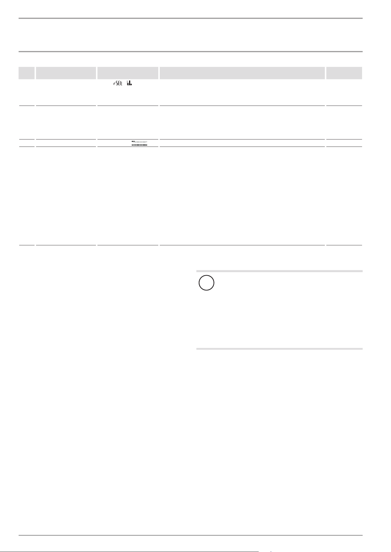
menu Description Explanations Screen | display
I1 Flow rate The current flow rate
is shown.
Flow rate in l/min or
gpm
I2 Time The current time is
shown.
Time
I3
Energy consump-
tion
The amount of en-
ergy consumed is
shown.
Value in kWh
I4 Water consump-
tion
The amount of water
consumed is shown.
Value in m³ or gal
Note
The consumption values are calculated starting from the
last reset.
4.9 Settings in the parameter menu
4.9.1 Activating the parameter menu
f Briefly press and hold "i" for more than 5seconds until "P1"
appears, then continue by briefly pressing "i".
f In the selected parameter menu, turn the temperature selec-
tor to the required display/ setting.
OpErATiON
Settings and displays
www.stiebel-eltron.com DHE AU | 7
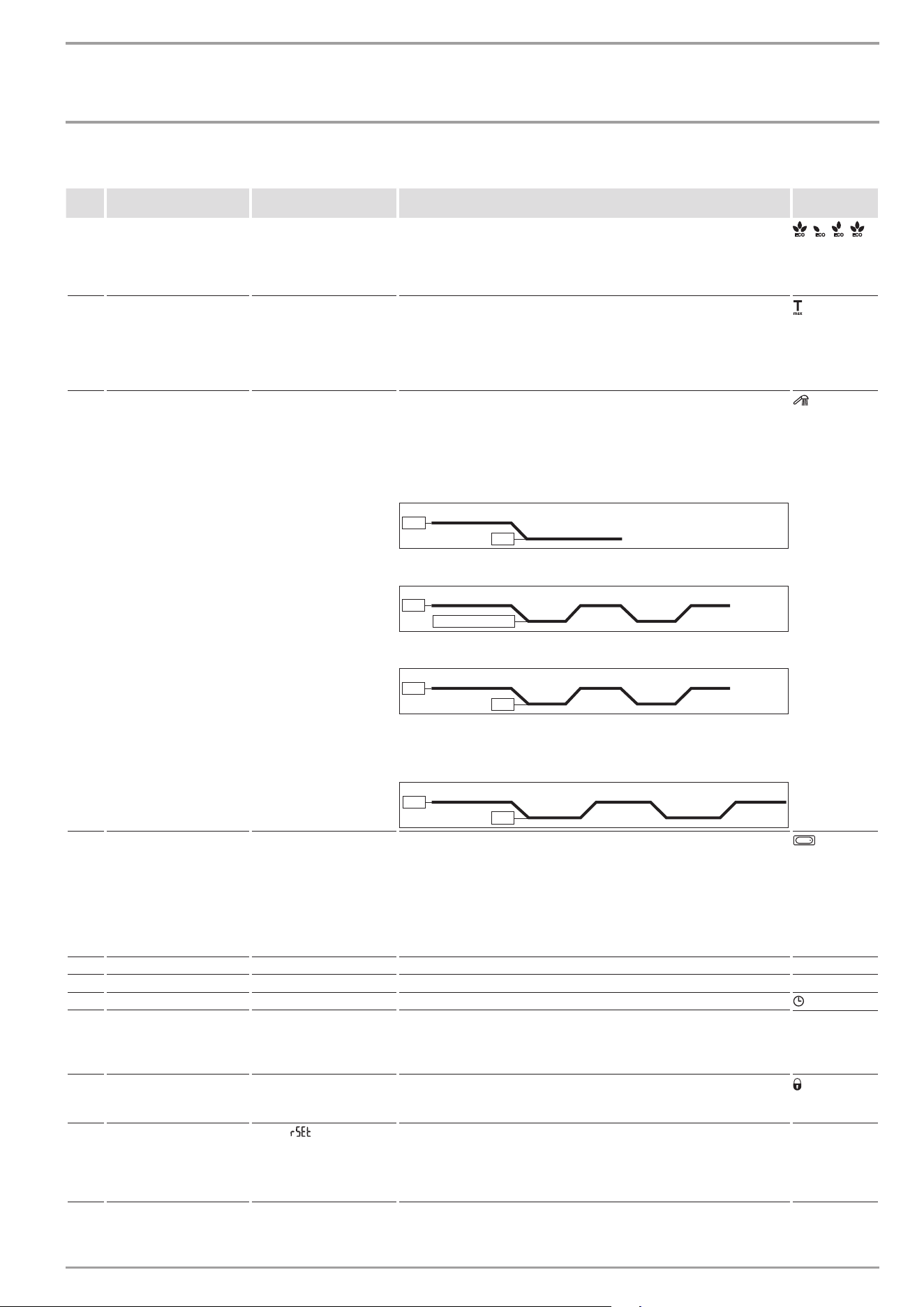
4.9.2 Parameter menu
menu Description Selectable display |
setting
Explanations Symbol |
display
P1
ECO water and energy
saving function
OFF | ECO1 | ECO2 | ECO3
The ECO function enables you to limit the flow rate to a maximum
value.
Flow rate limit:
8l/min with "ECO1" | 7l/min with "ECO2" | 6l/min with "ECO3" | No
flow rate limit with "OFF".
|
|
|
P2
Temperature limit Tmax
OFF | 20.0 | 20.5 ...°C or
68 | 69 ...°F
The temperature limit allows you as a user to restrict the adjustable
set temperature at the appliance to a maximum value. Check that the
upper temperature limit has been correctly applied.
Your qualified contractor can set an additional temperature limit for
anti-scalding protection. This temperature then dictates the upper
limit of the setting range for the temperature limit function.
P3
Wellness showers
OFF | Pro1 | Pro2 | Pro3|
Pro4
The Wellness shower program lets you choose from 4 different alter-
nating shower programs.
WW = domestic hot water, KW = cold water, min = minutes, sec = sec-
onds
- 1 Cold prevention
To strengthen the body, we recommend finishing off with a cold
shower; this will trigger a reflex in the body to warm up.
WW
KW
3 min
- 2 Winter refreshment
An invigorating end to a winter shower with a final warm-up.
WW
KW
3 min
10 sec
10 sec
10 sec
10 sec
WW - 10 °C | 50 °F
- 3 Summer fitness program
A quick contrast shower to increase fitness with a final warm-up.
WW
KW
3 min
10 sec
10 sec
10 sec
10 sec
- 4 Circulation boost program
Shower your arms and legs with cold water to boost circulation. Spray
from the hands and feet towards the body. You can then repeat this
process with hot water.
WW
KW
3 min 30 sec
20 sec
30 sec
20 sec
P4
Automatic water volume
control – set the volume
in the selected unit
OFF | 5 | 10 | ... 200l or
2... 52gal
With the automatic water volume control, you can preselect a volume
of water, e.g. for filling a bathtub. When the preselected water volume
is reached, the automatic control reduces the flow rate. The automatic
water volume control must be enabled on each occasion prior to fill-
ing the bath.
Example, filling a bath with 80litres (21gallons): When the bath has
been filled with 80litres (21gallons), the control automatically reduc-
es the flow rate to 4l/min (1gpm).
P5 Temperature unit C | F Select the temperature unit for all settings. °C| °F
P6 Volume unit L | GAL Select the volume unit for all settings. l | gal
P7 Time format 24h | 12h Select time format.
P8
Time setting
--:--
You can set the time using the 12 or 24hour clock:
- 12hours from 00:00 - 11:59= AM | 11:59 - 00:00= PM
- 24hours from 00:00 to 23:59
After a power cut, the time needs to be set again.
AM | PM (only
for 12h)
P9
Operating lock
ON | OFF
You can set the operating lock to "ON" or "OFF".
To disable the set operating lock:
f Press and hold "i" for more than 12seconds.
(only when
ON)
P10
Reset to factory settings
Reset ( )
You can restore the appliance to its factory settings. "rSEt" is shown
on the display.
f Press "1" and "2" simultaneously and hold for longer than 5sec-
onds. The display switches to "On" to confirm the reset.
f To confirm "On", press and hold "i" for more than 5seconds.
OpErATiON
Cleaning, care and maintenance
8 | DHE AU www.stiebel-eltron.com
menu Description Selectable display |
setting
Explanations Symbol |
display
P11
Resetting the consump-
tion values
Reset ( | )
You can reset the consumption values. "rSEt" is shown on the display.
f Press "1" and "2" simultaneously and hold for longer than 5sec-
onds. The display switches to "On" to confirm the reset.
f To confirm "On", press and hold "i" for more than 5seconds.
P12
Backlighting
Auto | On
You can adjust the display backlight.
- If "Auto" is selected, the backlight is switched on during heating
operation and each time an action is performed. If no action is per-
formed for 30seconds, the backlight is switched off again.
- If you select "On", the backlight will remain on constantly.
P13 Reduce backlighting 100% | 20% ( ) You can select 2levels of brightness for the backlight.
P14
Wireless module
After installation of a wireless module (with or without paired wire-
less remote control) in the appliance, menu item P14 is enabled and
"rc" appears on the programming unit display. You can pair one or
more wireless remote controls; to do so, follow the pairing procedure
on the appliance and the wireless remote control.
Pressing "1" on the appliance for longer than 5seconds starts the
pairing process, which is shown on the programming unit of the ap-
pliance by a progress bar on the display and the operating LED flash-
ing. Start the pairing process on the wireless remote control as de-
scribed in the relevant operating instructions. After successful pairing,
the operating LED on the appliance flashes briefly. An unsuccessful
pairing attempt is automatically terminated after 30seconds.
Pressing "2" on the appliance for longer than 5seconds unpairs all
connected wireless remote controls. During unpairing, "rc0" appears
on the display of the programming unit for 5seconds, then "rc" again.
4.9.3 Deactivating the parameter menu
f Exit the menu item by pressing "i" and holding for more than
5seconds. Alternatively: The system exits the menu item au-
tomatically 30seconds after the setting has been completed.
4.10 Recommended settings
Your instantaneous water heater offers maximum precision and
maximum convenience in DHW provision. Should you nonetheless
operate the appliance with a thermostatic valve, we recommend
that you:
f Adjust the set temperature on the appliance to over 50°C.
Then set the required set temperature on the thermostatic
valve.
Saving energy
The following recommended settings will result in the lowest en-
ergy consumption:
- 38°C for hand washbasins, showers, bath
- 55°C for kitchen sinks
Internal anti-scalding protection (qualified contractors)
If required, the qualified contractor can set a permanent temper-
ature limit, for example in nurseries, hospitals,etc.
Recommended setting for operation with a thermostatic valve
and water preheated by solar energy
f Set the temperature at the instantaneous water heater to the
maximum temperature.
Following an interruption to the water supply
!
Material losses
To ensure that the bare wire heating system is not dam-
aged following an interruption to the water supply, the
appliance must be recommissioned by taking the follow-
ing steps.
f Disconnect the appliance from the power supply by
removing the fuses/tripping the MCBs.
f Open the tap for one minute until the appliance and
its upstream cold water inlet line are free of air.
f Switch on the power supply again.
5. Cleaning, care and maintenance
f Never use abrasive or corrosive cleaning agents. A damp
cloth is sufficient for cleaning the appliance.
f Check the taps regularly. Limescale deposits at the tap out-
lets can be removed using commercially available descaling
agents.
www.stiebel-eltron.com DHE AU | 9
OpErATiON | iNSTAllATiON
Troubleshooting
6. Troubleshooting
problem Cause remedy
The appliance will not
start despite the DHW
valve being fully open.
There is no power.
Check the fuses/ MCBs in
your fuse box/ distribu-
tion board.
The aerator in the tap
or the shower head is
scaled up or dirty.
Clean and/or descale the
aerator or shower head.
The water supply has
been interrupted.
Vent the appliance and
the cold water inlet line.
When hot water is being
drawn off, cold water
flows for a short period.
The air sensor is detect-
ing air in the water. It
briefly switches off the
heating output.
The appliance restarts
automatically after
1minute.
The required tempera-
ture cannot be set.
The high limit safety
cut-out and/or internal
anti-scalding protection
are enabled.
Deactivate the temper-
ature limit. The internal
anti-scalding protection
can only be adjusted by
qualified contractors.
The flow rate is too low.
ECO function is enabled.
Select a different ECO
level or disable the ECO
function.
No settings can be made
on the programming
unit.
The operating lock is
enabled.
To deactivate the oper-
ating lock, press the "i"
button for more than
12seconds.
Note
Programming unit displays and selected settings are re-
tained following a power failure.
If you cannot remedy the fault, contact your qualified contractor.
To facilitate and speed up your enquiry, please provide the serial
number from the type plate (000000-0000-000000).
Nr. 000000-0000-00000
Nr. 000000-0000-00000
D0000053312
iNSTAllATiON
7. Safety
Only a qualified contractor should carry out installation, commis-
sioning, maintenance and repair of the appliance.
7.1 General safety instructions
We guarantee trouble-free function and operational reliability only
if original accessories and spare parts intended for the appliance
are used.
!
Material losses
Observe the maximum inlet temperature. Higher tem-
peratures may damage the appliance. You can limit the
maximum inlet temperature by installing a central ther-
mostatic valve.
WARNING Electrocution
This appliance contains capacitors which are discharged
when disconnected from the power supply. The capacitor
discharge voltage may briefly exceed60VDC.
7.2 Shower operation
CAUTION Burns
- The appliance is suitable for supplying a shower
(shower operation). If the appliance is also or exclu-
sively used for shower operation, the qualified con-
tractor must adjust the temperature setting range to
43°C using the internal anti-scalding protection on
the appliance. When using preheated water, ensure
that the inlet temperature does not exceed 55°C.
- In Australia, the use of a temperature controller is
required to meet the requirements of AS3498 when
showers, bathtubs or washbasins are supplied with
water. The maximum temperature of 50°C must not
be exceeded.
7.3 Instructions, standards and regulations
Note
Observe all applicable national and regional regulations
and instructions.
Note
The installation of this appliance shall conform to the
Plumbing Code of Australia (PCA), and the New Zealand
Building Code.
- The IP24/ IP25 protection rating can only be ensured with a
correctly fitted cable grommet.
- The electrical resistivity of the water must not fall below that
stated on the type plate. In a linked water network, take into
consideration the lowest electrical resistivity of the water.
Your water supply utility will advise you of the electrical re-
sistivity or conductivity of the water in your area.
iNSTAllATiON
Appliance description
10 | DHE AU www.stiebel-eltron.com
8. Appliance description
8.1 Standard delivery
The following are delivered with the appliance:
- Wall mounting bracket
- Installation template
- 2 plugs
- 2 extensions
- 2 caps
- 2 tees
- 8 flat gaskets
- Strainer
- Plastic profile washer
- Plastic connection pieces/ installation aid
- Cover and back panel guides
- Jumper for internal anti-scalding protection
8.2 Accessories
Wireless remote control
- FFB4SetAP
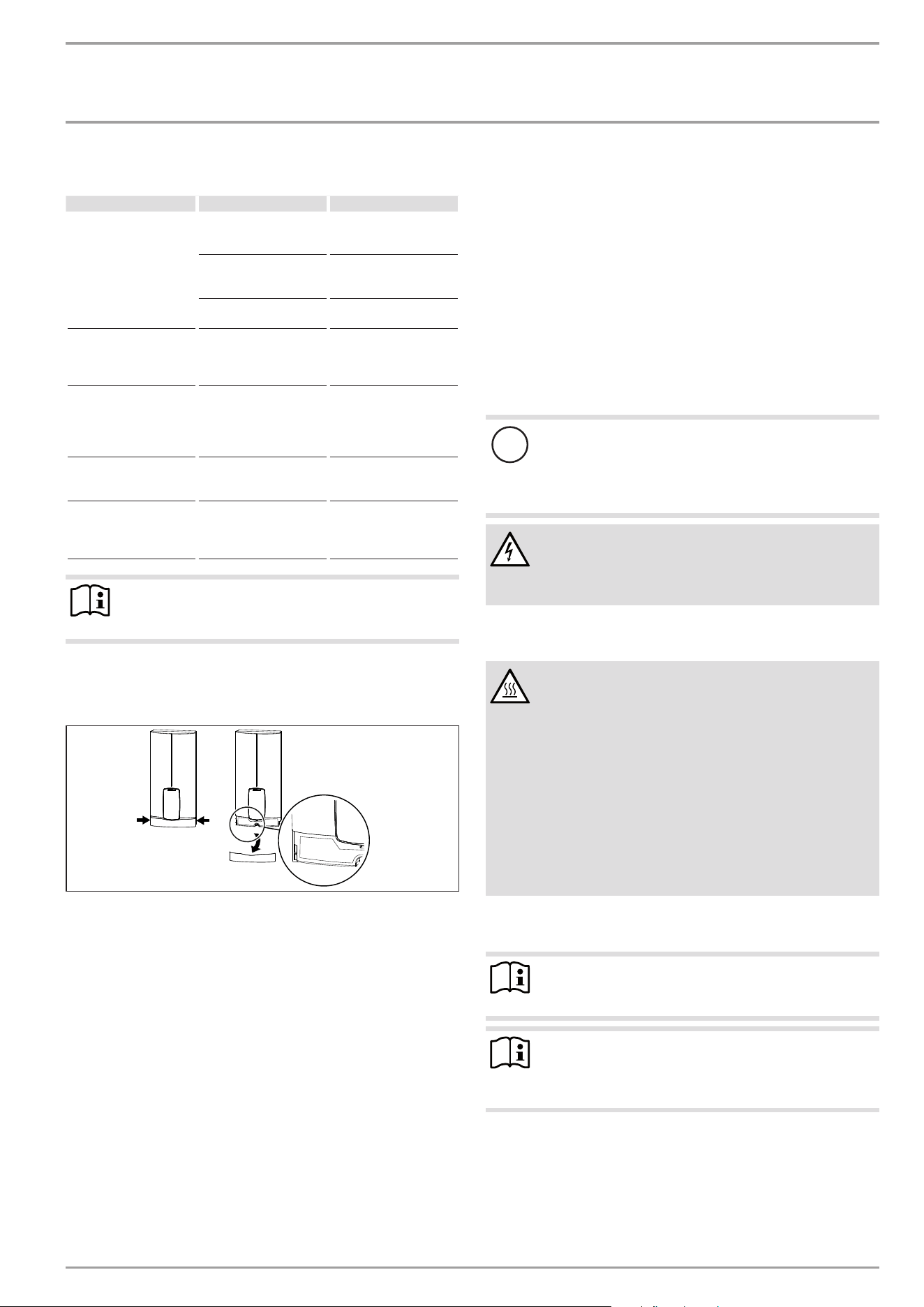
9. Preparation
9.1 Installation site
!
Material losses
Install the appliance in a room that is free from the risk
of frost.
f Always install the appliance vertically and near the draw-off
point. For horizontal installation, see chapter "Installation
alternatives/ Horizontal installation of the appliance".
The appliance is suitable for undersink and oversink installation.
Undersink installation
D0000056242
1
2
1 Cold water inlet
2 DHW outlet
Oversink installation
D0000057030
12
1 Cold water inlet
2 DHW outlet
Note
f Mount the appliance on the wall. The wall must have
sufficient load bearing capacity.
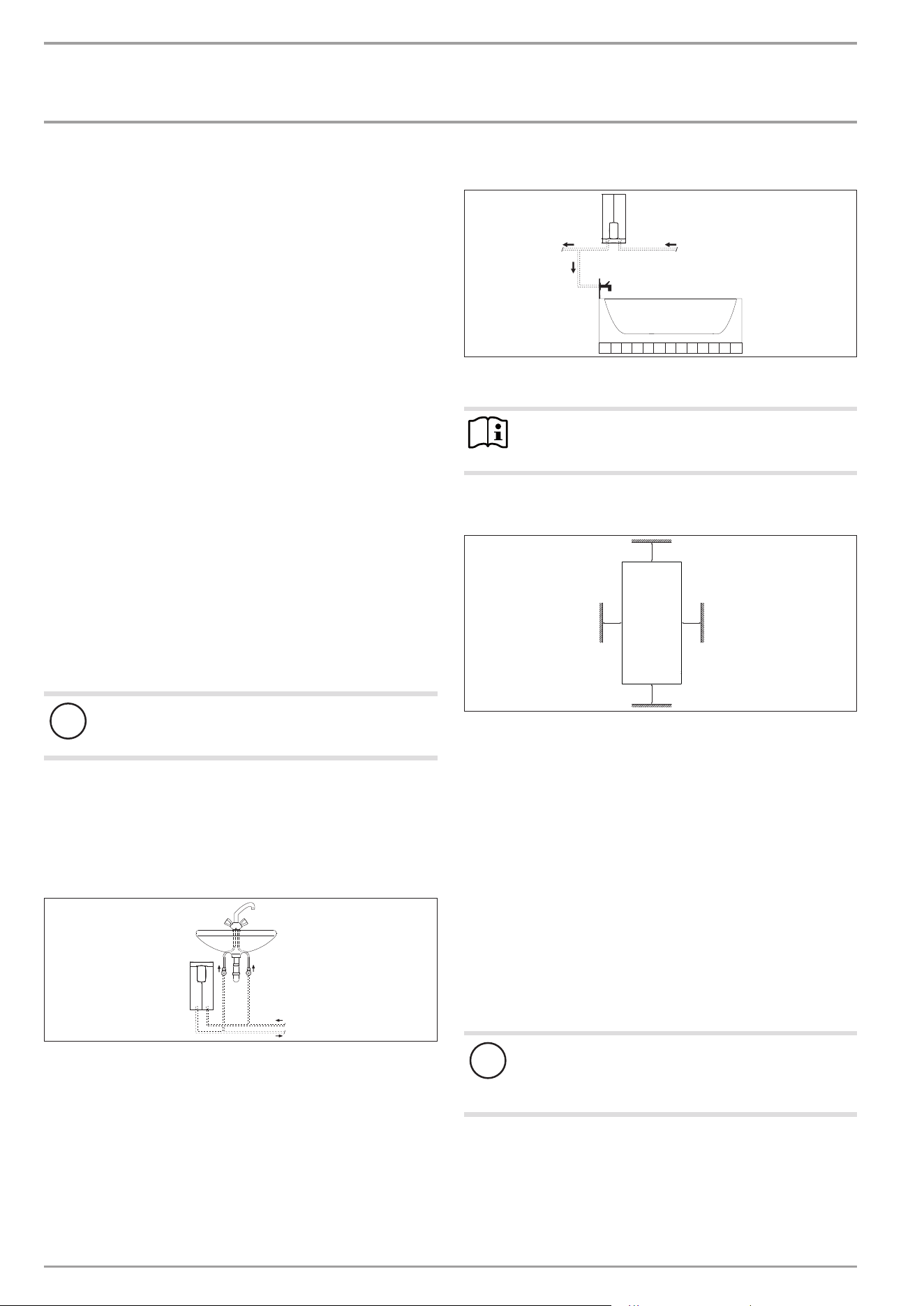
9.2 Minimum clearances
≥50≥50
≥90
≥90
D0000060809
f Maintain the minimum clearances to ensure trouble-free op-
eration of the appliance and facilitate maintenance work.
9.3 Water installation
f Flush the water line thoroughly.
Fittings
Use appropriate pressure taps. Open vented taps are not per-
missible.
Permissible water line materials
- Cold water inlet line:
Pipes made from galvanised steel, stainless steel, copper or
plastic
- DHW outlet line:
Pipes made from stainless steel, copper or plastic
!
Material losses
If plastic pipework systems are used, take into account
the maximum inlet temperature and the maximum per-
missible pressure.
Flow rate
f Ensure that the flow rate for switching on the appliance is
achieved.
f If the required flow rate is not achieved when the draw-off
valve is fully open, increase the water line pressure.
iNSTAllATiON
installation
www.stiebel-eltron.com DHE AU | 11
10. Installation
factory settings DHE 18 AU DHE 27 AU
Internal anti-scalding protection Tmax (= 60°C) Tmax (= 60°C)
Standard installation DHE 18 AU DHE 27 AU
Electrical connection from below on
unfinished walls
x x
Water connection, installation on
finished walls
x x
For further installation options, see chapter "Alternative instal-
lation methods".
10.1 Standard installation
Note
This type of connection changes the IP rating of the ap-
pliance.
f Change the type plate. Cross out "IP25" and mark
the box "IP24". Use a ballpoint pen to do this.
Opening the appliance
D0000053271
f Open the appliance by holding the fascia at the side and pull-
ing forwards away from the appliance cover. Undo the screw.
Pivot open the appliance cover.
D0000053272
f Remove the back panel by pressing the two locking tabs and
pulling the lower back panel section forwards.
Preparing the power cable on unfinished walls, for connection
from below
160
30
D0000053273
1
1 Cable entry installation aid
f Prepare the power cable.
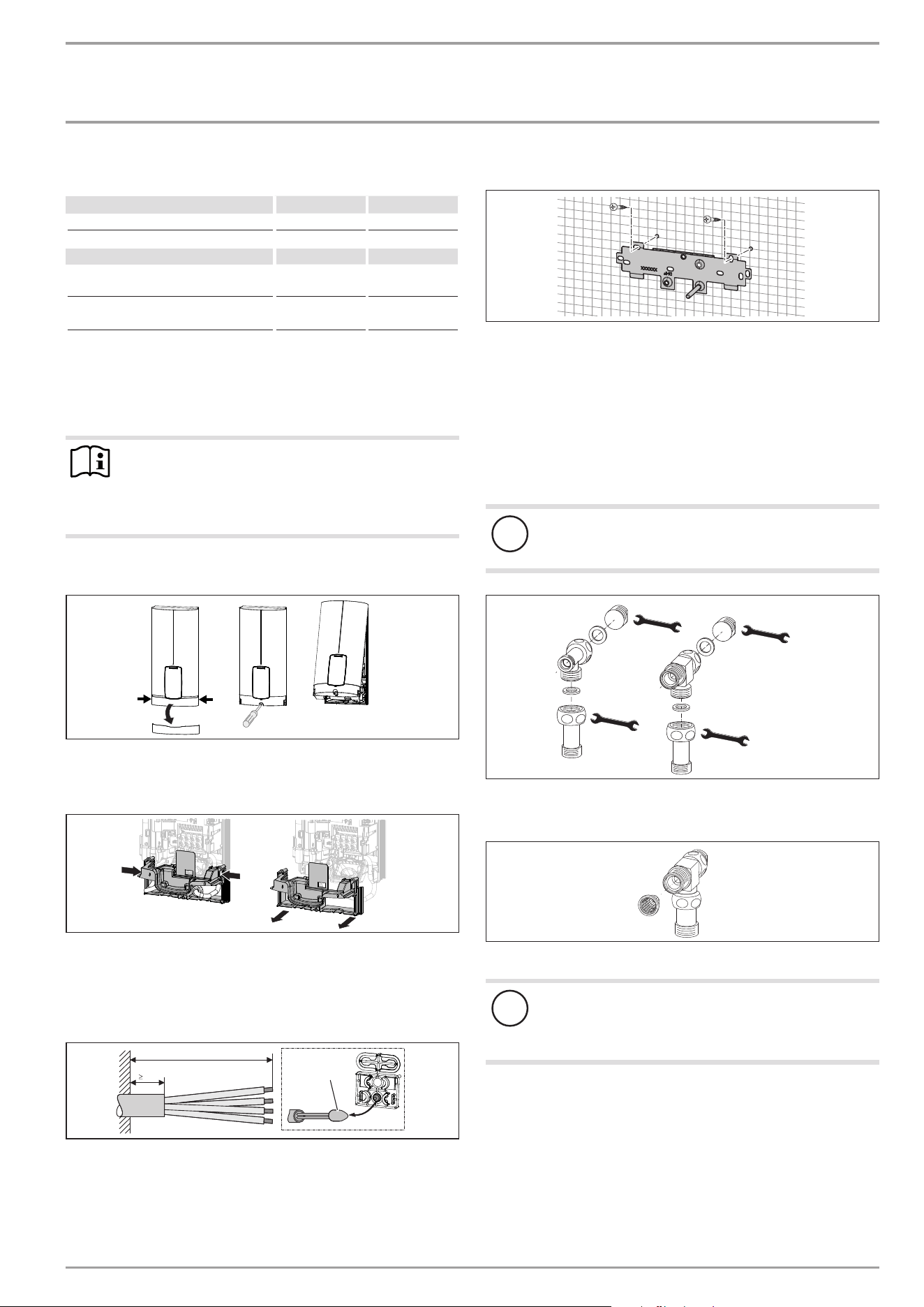
Fitting the wall mounting bracket
D0000059694
f Mark out the holes for drilling using the installation tem-
plate. If the appliance is to be installed on finished walls, also
mark out the fixing hole in the lower section of the template.
f Drill the holes and secure the wall mounting bracket at 2
points using suitable fixing materials (screws and rawl plugs
are not part of the standard delivery).
f Fit the wall mounting bracket.
Preparing the water connection
!
Material losses
Carry out all water connection and installation work in
accordance with regulations.
24
5 Nm
24
5 Nm
19
5 Nm
19
5 Nm
D0000041720
f Remove the caps from the tees.
f Fit the plugs and the extensions with gaskets.
D0000041721
f Fit the strainer in the tee for the cold water inlet.
!
Damage to the appliance and environment
The strainer must be fitted for the appliance to function.
f When replacing the appliance, check that the strain-
er is present.

iNSTAllATiON
installation
12 | DHE AU www.stiebel-eltron.com
Installing the appliance
Note
If you are installing the appliance with flexible pipe con-
nections, also secure the back panel with a screw.
D0000077728
1
2
1 Cable entry installation aid
2 Cable grommet
Use the installation aid for easier wiring access through the cable
grommet (see plastic parts set supplied).
f Remove the cable grommet from the back panel.
f Pull the cable grommet over the cable sheath of the power
cable. For large cable cross-sections, enlarge the hole in the
cable grommet if necessary.
D0000077722
f Remove the transport protection plugs from the appliance
pipe connections.
f Bend the power cable 45° upwards.
f Route the power cable and cable grommet through the back
panel from the rear.
f Install the appliance on the threaded studs of the wall
mounting bracket.
f Press the back panel firmly into place, aligning it correctly.
f Lock the fixing toggle by turning it 90° clockwise.
f Pull the cable grommets into the back panel until both lock-
ing tabs engage.
24
5 Nm
19
3 Nm
D0000077727
f Screw the pre-assembled parts with flat gaskets to the cold
water and DHW pipes of the appliance.
f Fit the cold water inlet pipe and the DHW outlet pipe from
the pipework with flat gaskets to the extensions from the
appliance.
Making the electrical connection
WARNING Electrocution
Carry out all electrical connection and installation work
in accordance with relevant regulations.
WARNING Electrocution
The connection to the power supply must be in the form
of a permanent connection in conjunction with the re-
movable cable grommet. Ensure the appliance can be
separated from the power supply by an isolator that dis-
connects all poles with at least 3mm contact separation.
WARNING Electrocution
Ensure that the appliance is earthed.
!
Material losses
Observe the type plate. The specified rated voltage must
match the power supply.
f Connect the power cable to the mains terminal.
D0000053286
2
3
1
1 Lower back panel section
2 Connection piece in the standard delivery
3 Screw
If using threaded fittings on finished walls, the lower back panel
section can also be installed after fitting the taps. To do this, carry
out the following steps:
f Cut open the lower back panel section.
f Fit the lower back panel section by bending it out at the sides
and guiding it over the pipes.
f Insert the connection pieces into the lower back panel sec-
tion from behind.
f Click the lower back panel section into place.
f Secure the lower back panel section with a screw.
!
Material losses
The cover plate of the lower back panel section must not
bend when installed.
iNSTAllATiON
Commissioning
www.stiebel-eltron.com DHE AU | 13
11. Commissioning
11.1 Preparation
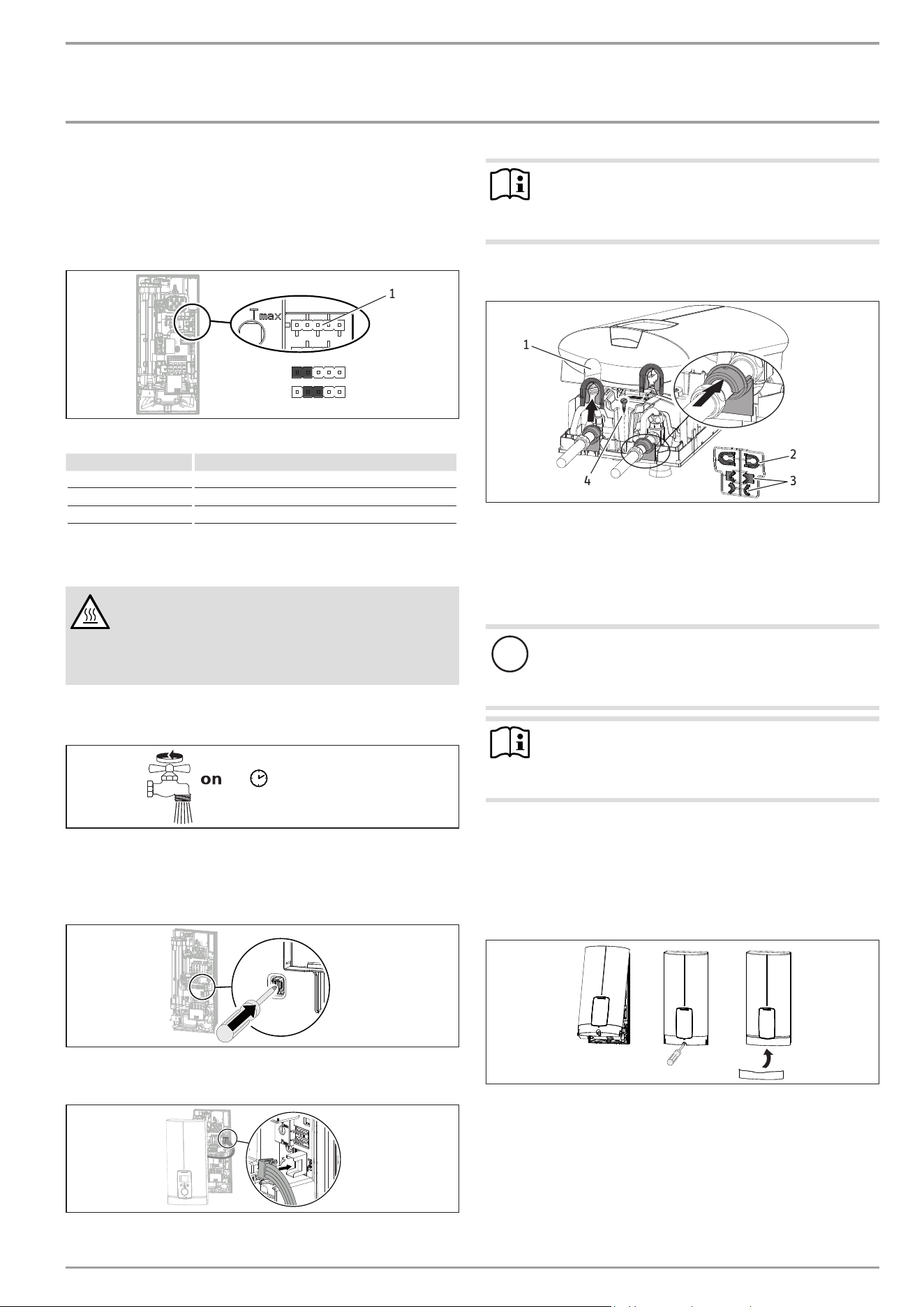
Internal anti-scalding protection via jumper slot
43 °C
Tmax
D0000077020
1
1 Jumper for anti-scalding protection setting
Jumper position Description
43 °C
Tmax Factory setting (60°C)
No jumper Limited to 43°C
f Install the "Anti-scalding protection setting" jumper in the
required position on the top pin strip.
CAUTION Burns
If the appliance is supplied with preheated water, the
internal anti-scalding protection may be exceeded.
f In this case, limit the temperature with an upstream
central thermostatic valve.
11.2 Initial start-up
≥ 60 s
D0000053277
f Open and close all connected draw-off valves several times,
until all air has been purged from the pipework and the
appliance.
f Carry out a tightness check.
D0000053278
f Activate the safety switch by firmly pressing the reset button
(the appliance is delivered with the safety switch disabled).
D0000073198
f Connect the programming unit connecting cable to the PCB.
Note
For undersink installation, the appliance cover should be
turned the other way up for easier operation; see chapter
"Installation alternatives/ Rotated appliance cover".
Fit the appliance cover
D0000040777
1
2
3
4
1 Pipe knock-out
2 Cover guides
3 Back panel guides
4 Fixing screw (not part of the standard delivery)
f Cleanly cut or break out the knock-out openings in the appli-
ance cover. If necessary, use a file.
!
Material losses
If you cut open the wrong knock-out in the appliance
cover by mistake, you must use a new appliance cover.
Note
You can compensate for a slight connection pipe offset
using the tabs on the cover guides. If the connection pipes
are offset, do not fit any back panel guides.
f When installing connection pipes without offset, break off
the tabs on the cover guide pieces.
f Click the cover guides into place in the openings.
f Position the back panel guides on the extensions. Push them
together. Then push the guides against the back panel as far
they will go.
D0000053280
f Hook the appliance cover at the top rear into the back panel.
Pivot the appliance cover downwards. Check that the appli-
ance cover is securely seated both top and bottom.
f Secure the appliance cover with the screw.
f Fit the fascia to the appliance cover.
f Remove the protective film from the user interface.
iNSTAllATiON
Appliance shutdown
14 | DHE AU www.stiebel-eltron.com
D0000053281
f Switch on the power supply.
11.2.1 Appliance handover
f Explain the appliance function to users and familiarise them
with how it works.
f Make the user aware of potential dangers, especially the risk
of scalding.
f Hand over the instructions.
11.3 Recommissioning
!
Material losses
To ensure that the bare wire heating system is not dam-
aged following an interruption to the water supply, the
appliance must be recommissioned by taking the follow-
ing steps.
f Disconnect the appliance from the power supply by
removing the fuses/tripping the MCBs.
f Open the tap for at least one minute until the appli-
ance and its upstream cold water inlet line are free
of air.
f Switch on the power supply again.
12. Appliance shutdown
f Isolate all poles of the appliance from the power supply.
f Drain the appliance (see chapter "Maintenance/ Draining the
appliance").
13. Installation alternatives
Overview of installation alternatives
Electrical connection ip rating
On unfinished walls, connected from above IP25
On unfinished walls, connected from below, short
power cable
IP25
Finished walls IP24
Water connection ip rating
Unfinished walls IP25
Other ip rating
Installation with offset tiles IP25
Rotated appliance cover IP25
Horizontal installation of the appliance IP24
WARNING Electrocution
Before any work on the appliance, disconnect all poles
from the power supply.
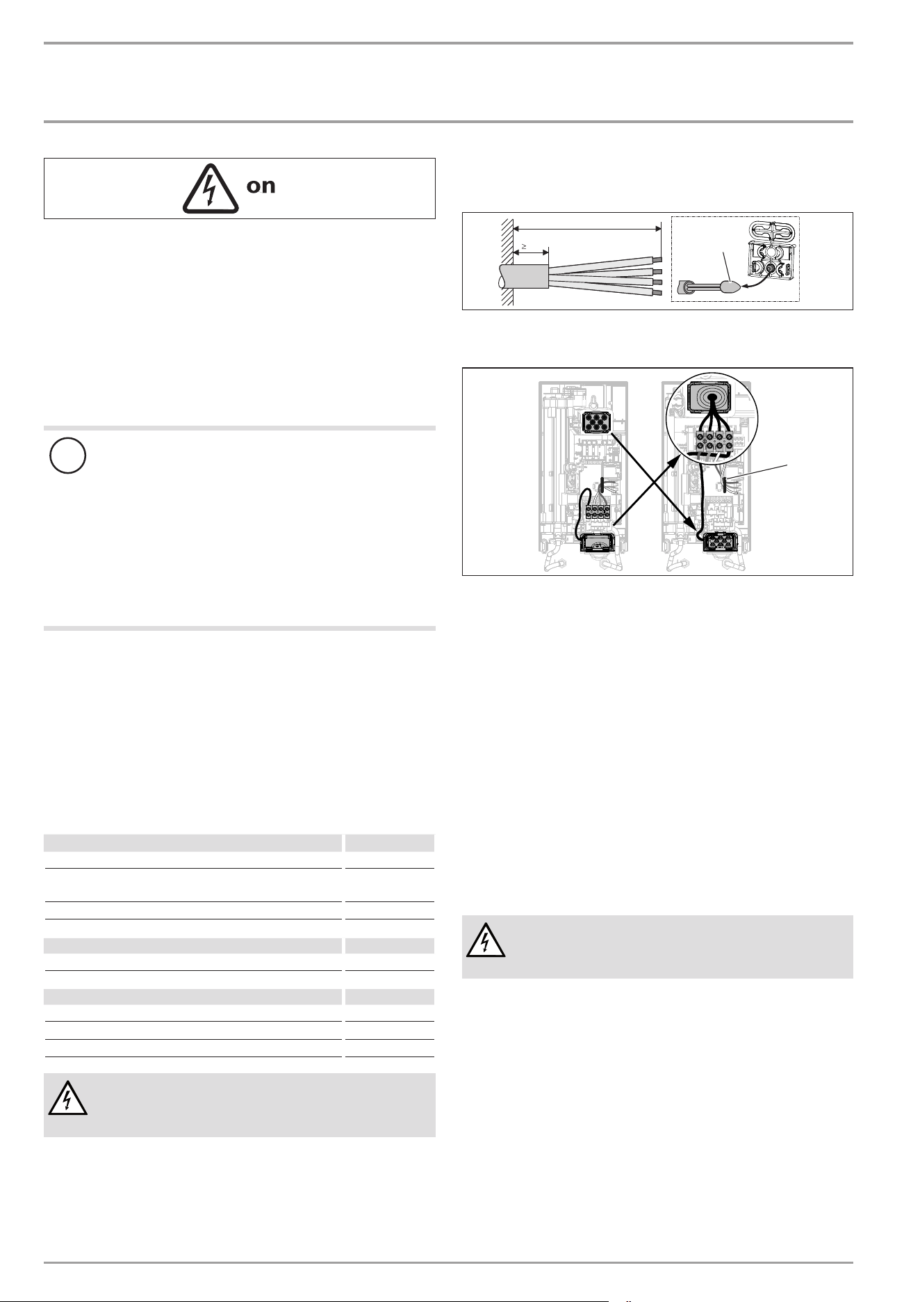
13.1 Electrical connection from above on unfinished
walls
140
30
D0000076507
1
1 Cable entry installation aid
f Prepare the power cable.
D0000053282
1
1 Cable routing
f Reposition the mains terminal from the bottom to the top. To
do this, undo the fixing screw. Turn the mains terminal with
connecting cables 180° clockwise. Route the cable around
the cable guide when doing so. Secure the mains terminal in
place.
f Replace the cable grommets.
f Install the cable grommet from the top at the bottom.
f Pull the cable grommet over the cable sheath of the power
cable.
f Install the appliance on the threaded studs of the wall
mounting bracket.
f Push the back panel firmly against the wall. Lock the fixing
toggle by turning it 90° clockwise.
f Pull the cable grommets into the back panel until both lock-
ing tabs engage.
f Connect the power cable to the mains terminal.
WARNING Electrocution
The connecting wires must not protrude beyond the level
of the mains terminal.
iNSTAllATiON
installation alternatives
www.stiebel-eltron.com DHE AU | 15
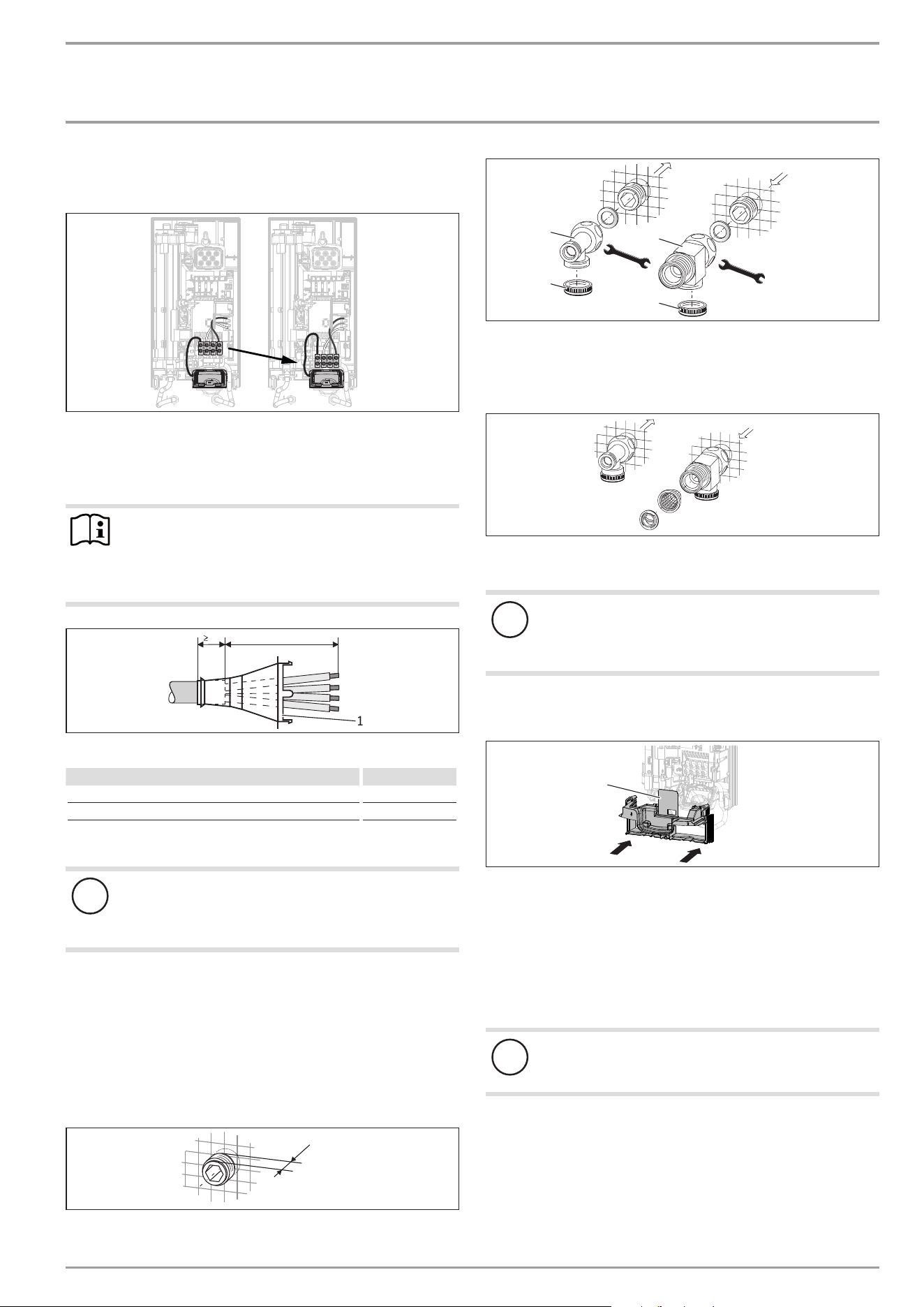
13.2 Electrical connection on unfinished walls from
below with short power cable
D0000060387
f Reposition the mains terminal further downwards. To do this,
undo the fixing screw. Secure the mains terminal in place.
13.3 Electrical connection on finished walls
Note
This type of connection changes the IP rating of the ap-
pliance.
f Change the type plate. Cross out "IP25" and mark
the box "IP24". Use a ballpoint pen to do this.
A
30
D0000076506
1
1 Cable grommet
Electrical connection on finished walls Dimension A
Positioned in lower section of appliance 160
Positioned in upper section of appliance 110
f Prepare the power cable. Fit the cable grommet.
!
Material losses
If you break out the wrong knock-out in the back panel/
appliance cover by mistake, you must use a new back
panel/appliance cover.
f Cleanly cut and break out the required cable entries from the
back panel and appliance cover (for the positions, see chap-
ter "Specification/ Dimensions and connections"). Deburr any
sharp edges with a file.
f Route the power cable through the cable grommet.
f Connect the power cable to the mains terminal.
13.4 Water installation on unfinished walls
12
D0000053319
f Seal and screw in the twin nipples (not included in standard
delivery).
5 Nm
24
5 Nm
24
D0000041724
2
3
3
1
1 Tee for cold water
2 Tee for domestic hot water
3 Cap
f Fit the water connections.
D0000043291
f Fit the strainer and the plastic profile washer in the tee for
the cold water inlet.
!
Material losses
The strainer must be fitted for the appliance to function.
f When replacing the appliance, check that the strain-
er is present.
f Screw the connection pipes from the appliance to the tee.
f Open the shut-off valve in the cold water inlet line.
D0000053275
1
1 Diffuser on lower back panel
f Fit the lower back panel section into the back panel. Check
that both locking tabs are engaged.
f Align the mounted appliance by undoing the fixing toggle,
aligning the power supply and back panel, and then re-tight-
ening the fixing toggle. If the back panel does not sit flush
against the wall, you can secure the appliance at the bottom
with an additional screw.
!
Material losses
The cover plate of the lower back panel section must not
bend when installed.
iNSTAllATiON
installation alternatives
16 | DHE AU www.stiebel-eltron.com
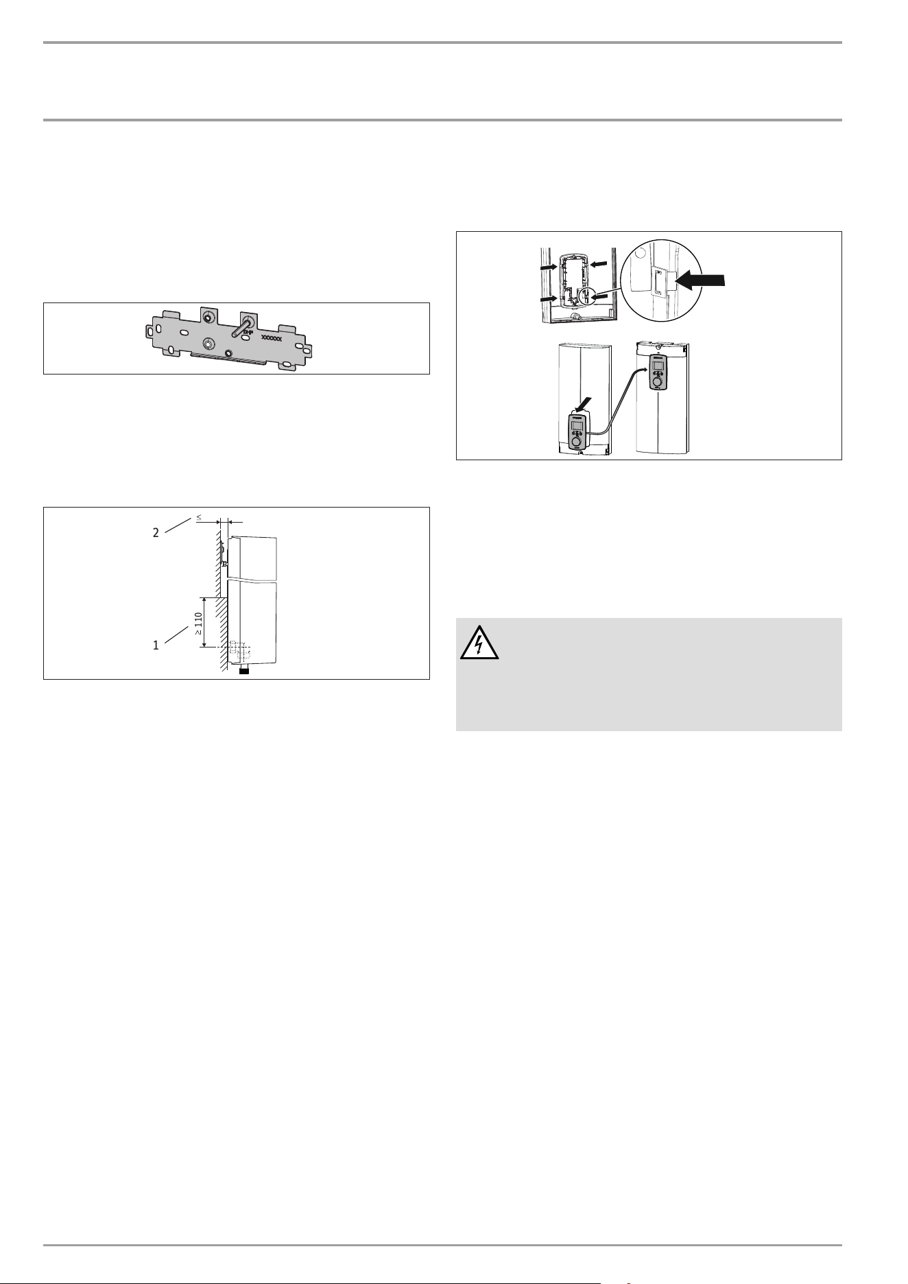
13.5 Wall mounting bracket when replacing an
appliance
An existing STIEBELELTRON wall mounting bracket may be used
when replacing appliances (except the DHF instantaneous water
heater), as long as the fixing screw is in the lower right position.
Replacing a DHF instantaneous water heater
26�02�02�0815�
f Reposition the fixing screw on the wall mounting bracket (the
fixing screw has a self-tapping thread).
f Rotate the wall mounting bracket 180° and mount it on the
wall (the DHF logo is then turned towards you).
13.6 Installation with offset tiles
110
20
2
1
D0000043278
1 Minimum contact area of the appliance
2 Maximum tile offset
f Adjust the wall clearance. Lock the back panel in place using
the fixing toggle (turn 90° clockwise).
13.7 Rotated appliance cover
The appliance cover should be turned the other way up for un-
dersink installation.
D0000073012
f Remove the programming unit from the appliance cover by
pressing the locking hooks and removing the programming
unit.
f Turn the appliance cover (not the appliance) the other way
up and refit the programming unit. Push the programming
unit home in parallel until all locking tabs engage. When
engaging the locking tabs, apply counter pressure by pushing
against the appliance cover from the inside.
WARNING Electrocution
All 4locking tabs on the programming unit must click into
place. The locking tabs must be complete and undam-
aged. If the programming unit is not inserted correctly,
user protection against contact with live components
cannot be ensured.
f Insert the connecting cable plug of the programming unit
into the PCB (see chapter "Commissioning/ Initial start-up").
f Hook the appliance cover in at the bottom. Pivot the appli-
ance cover up to the back panel.
f Secure the appliance cover.
f Fit the cover onto the appliance cover.
13.8 Operation with preheated water
You can limit the maximum inlet temperature by installing a cen-
tral thermostatic valve.
iNSTAllATiON
Service information
www.stiebel-eltron.com DHE AU | 17
13.9 Horizontal installation of the appliance
Note
For the horizontal installation alternative, please note
the following points:
- Installation is only permissible with direct wall
mounting.
- The installation versions "Installation with offset
tiles" and "Rotated appliance cover" are not permis-
sible.
- This type of connection changes the IP rating of the
appliance. Cross out "IP25" on the type plate and
mark the box "IP24". Use a ballpoint pen to do this.
Horizontal installation
The appliance can also be mounted horizontally on the wall
(turned 90° to the left, with the water connections on the right).
The installation, water and electrical connections are described
in chapters "Standard installation" and "Installation alternatives".
1
2
D0000076919
1 Cold water inlet
2 DHW outlet
Preparation
The appliance cover must be provided with a condensate drain
opening of min. ∅5.0mm to max. ∅6.0mm at the marked po-
sition.
50
Ø 5,0
D0000076914
1 2
1 Appliance cover with opening for condensate drain
2 Back panel with additional fixing screw
f Drill a hole from the outside through the dismantled appli-
ance cover at the marked point. Alternatively, you can punch
a hole in the appliance cover from the inside at the marked
point. In this case, you must then enlarge the hole to the
required diameter from the outside. Deburr any sharp edges
with a file.
f Secure the appliance back panel with an additional screw.
!
Material losses
An appliance cover with an existing condensate drain
opening must no longer be used for vertical installation
of the appliance.
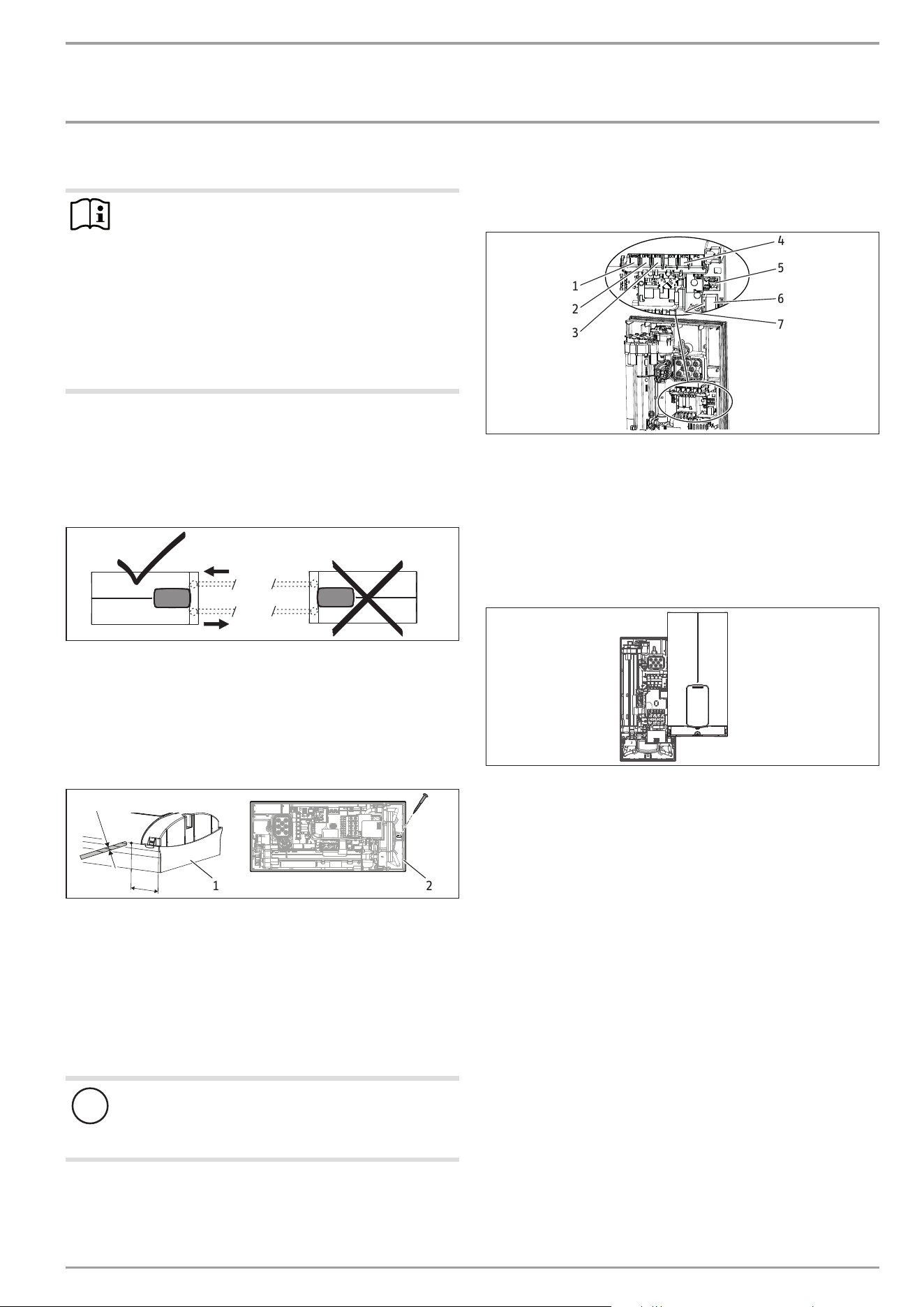
14. Service information
Overview of connections
D0000073174
1
2
3
4
5
6
7
1 Motorised valve
2 Flow sensor
3 High limit safety cut-out, automatic reset
4 NTC sensor
5 Pin strip for anti-scalding protection
6 Programming unit plug-in position
7 Diagnostic traffic lights
Appliance cover retainer
D0000056216
iNSTAllATiON
Troubleshooting
18 | DHE AU www.stiebel-eltron.com
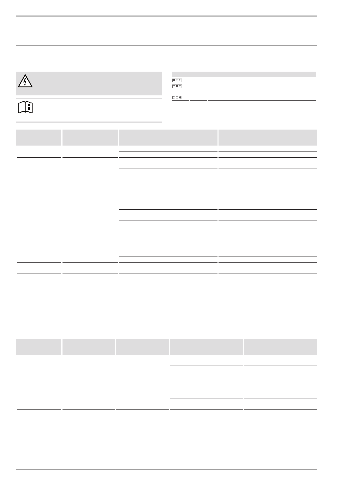
15. Troubleshooting
WARNING Electrocution
To test the appliance, it must be connected to the power
supply.
Note
When testing the appliance using the diagnostic traffic
lights, water must be flowing.
Signals of the diagnostic traffic lights (lED)
Red Lights up in the event of a fault
Yellow Illuminates in heating mode/flashes when output limit
reached
Green Flashing: Appliance connected to power supply
Diagnostic traffic
lights (draw-off
mode)
fault Cause remedy
No LED illuminates Appliance does not heat up
One or more power supply phases are missing Check the fuses in the distribution board
PCB faulty Replace the function module
Green flashing,
yellow off, red off
No DHW
Appliance starting flow rate not reached; shower
head/aerator scaled up
Descale/replace the shower head/aerator
Appliance starting flow rate not reached; strainer in
cold water inlet dirty
Clean strainer
Flow meter not plugged in Check plug-in connection; correct if necessary
Flow meter faulty or dirty Replace flow meter
PCB faulty Replace the function module
Green flashing,
yellow on, red off
No display
Loose connecting cable between PCB and program-
ming unit
Check plug-in connections; correct if necessary
Faulty connecting cable between PCB and program-
ming unit
Check connecting cable; replace if necessary
Programming unit faulty Replace programming unit
PCB faulty Replace the function module
Green flashing,
yellow on, red off
No DHW; outlet temperature
does not match set value
Tap faulty Replace tap
Outlet sensor faulty Replace outlet sensor
Heating system faulty Replace the function module
PCB faulty Replace the function module
Green flashes,
yellow flashes, red off
No DHW; outlet temperature
does not match set value
Motorised valve faulty Replace motorised valve
Green flashing,
yellow off, red on
No DHW; outlet temperature
does not match set value
One or more power supply phases are missing Check the fuses in the distribution board
Air detection has responded Continue draw-off for >1 min
15.1 Fault code display
If there is an appliance fault, the spanner flashes on the display.
f To call up the fault code display, press the "i" button for more
than 5seconds.
Diagnostic traffic
lights (draw-off
mode)
Display shown fault Cause remedy
Green flashing,
yellow off, red on
Spanner flashes (fault code
display E1 and spanner)
No DHW; outlet temperature
does not match set value
Safety switch not activated during
"Commissioning"
Activate the safety switch by firmly
pressing the reset button
Safety switch was triggered by high
limit safety cut-out
Check high limit safety cut-out (plug-in
connection, connecting cable); activate
safety switch
Safety switch responds again after high
limit safety cut-out has been checked;
high limit safety cut-out faulty
Replace high limit safety cut-out; ac-
tivate safety switch and draw-off with
maximum set value >1min
Safety switch responds again; PCB
faulty
Replace the function module
Green flashing,
yellow off, red on
Spanner flashes (fault code
display E2 and spanner)
No DHW PCB faulty (lead break or short circuit
in inlet sensor)
Replace the function module
Green flashing,
yellow off, red on
Spanner flashes (fault code
display E3 and spanner)
No DHW Short circuit in outlet sensor Check outlet sensor; replace if neces-
sary
iNSTAllATiON
maintenance
www.stiebel-eltron.com DHE AU | 19
16. Maintenance
WARNING Electrocution
Before any work on the appliance, disconnect all poles
from the power supply.
This appliance contains capacitors which are discharged
when disconnected from the power supply. The capacitor
discharge voltage may briefly exceed60VDC.
Draining the appliance
The appliance can be drained for maintenance work.
WARNING Burns
Hot water may escape when you drain the appliance.
f Close the shut-off valve in the cold water inlet line.
f Open all draw-off valves.
f Undo the pipe connections from the appliance.
f Store the dismantled appliance free from the risk of frost, as
water residues remaining inside the appliance can freeze and
cause damage.
Clean strainer
If the strainer in the threaded cold water fitting is dirty, clean it.
Close the shut-off valve in the cold water inlet line before remov-
ing, cleaning and refitting the strainer.
D0000077740
2
1
1 Strainer
2 Plastic profile washer
f Remove the plastic profile washer and the strainer.
f Clean the components.
f Fit the strainer and the plastic profile washer.
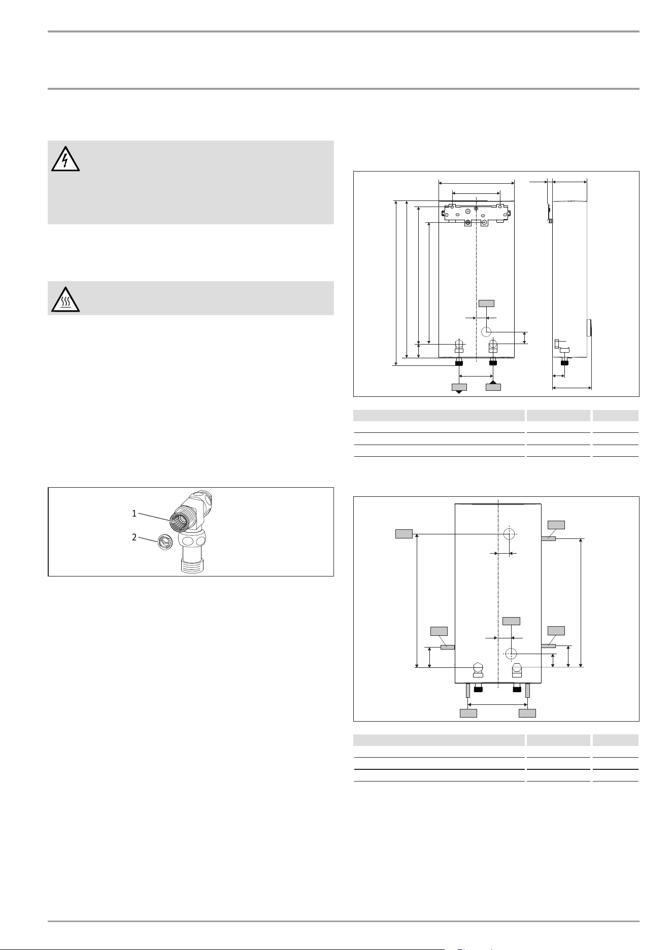
17. Specification
17.1 Dimensions and connections
466
481
225
35
35
414
38
105≤ 20
140
30
b02
100
c01c06
368
116
D0000077739
DHE AU
b02 Entry for electrical cables I Unfinished walls
c01 Cold water inlet Male thread G 1/2 A
c06 DHW outlet Male thread G 1/2 A
Alternative connection options
165
b04
b04
69
330
b04
69
325
b04
b04
b03
20
35
30
b02
D0000077736
DHE AU
b02 Entry for electrical cables I Unfinished walls
b03 Entry for electrical cables II Unfinished walls
b04 Entry electrical cables III Finished walls
iNSTAllATiON
Specication
20 | DHE AU www.stiebel-eltron.com
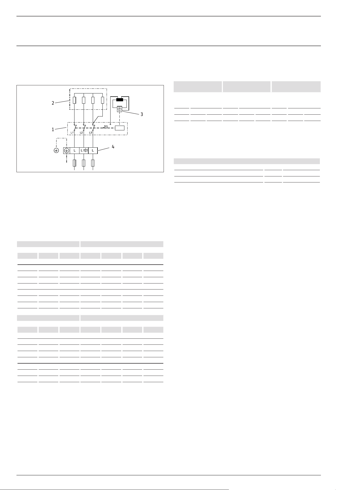
17.2 Wiring diagram
3/PE ~ 380-415V
D0000053424
1
3
4
2
1 Power PCB with integral safety switch
2 Bare wire heating system
3 High limit safety cut-out
4 Mains terminal
17.3 DHW output
The DHW output is subject to the connected power supply, the
appliance's connected load and the cold water inlet temperature.
The rated voltage and rated output can be found on the type plate.
Connected load in kW 38°C DHW output in l/min.
rated voltage Cold water inlet temperature
380V 400V 415V 5°C 10°C 15°C 20°C
DHE 18 AU
16.2 7.0 8.3 10.1 12.9
18.0 7.8 9.2 11.2 14.3
19.4 8.4 9.9 12.0 15.4
DHE 27 AU
23.5 10.2 12.0 14.6 18.7
26.0 11.3 13.3 16.1 20.6
28.0 12.1 14.3 17.4 22.2
Connected load in kW 50°C DHW output in l/min.
rated voltage Cold water inlet temperature
380V 400V 415V 5°C 10°C 15°C 20°C
DHE 18 AU
16.2 5.1 5.8 6.6 7.7
18.0 5.7 6.4 7.3 8.6
19.4 6.2 6.9 7.9 9.2
DHE 27 AU
23.5 7.5 8.4 9.6 11.2
26.0 8.3 9.3 10.6 12.4
28.0 8.9 10.0 11.4 13.3
17.4 Application areas/ conversion table
Electrical resistivity and electrical conductivity
Standard specifica-
tion at 15°C
20°C
25°C
Resis-
tivity
ρ≥
Conductivity σ ≤
Resis-
tivity
ρ≥
Conductivity σ≤
Resis-
tivity
ρ≥
Conductivity σ≤
Ω cm mS/m μS/cm Ω cm mS/m μS/cm Ω cm mS/m μS/cm
900 111 1111 800 125 1250 735 136 1361
17.5 Pressure drop
Fittings
Tap pressure drop at a flow rate of 10 l/min
Mono lever mixer tap, approx. MPa 0.04 - 0.08
Thermostatic valve, approx. MPa 0.03 - 0.05
Shower head, approx. MPa 0.03 - 0.15
Sizing the pipework
When calculating the size of the pipework, an appliance pressure
drop of 0.1MPa is recommended.
17.6 Fault conditions
In the event of a fault, loads up to 80°C at a pressure of 1.0 MPa
can occur very briefly in the installation.
www.stiebel-eltron.com DHE AU | 21
iNSTAllATiON | SOfTWArE COpYriGHT | ENVIRONMENT AND RECYCLING
Specication
17.7 Data table
DHE 18 AU DHE 27 AU
202658 202659
Electrical data
Rated voltage V 380 400 415 380 400 415
Rated output kW 16.2 18 19.4 23.5 26 28
Rated current A 24.7 26 27 35.6 37.7 38.9
Fuse protection A 25 25 32 40
Frequency Hz 50/60 50/60 50/- 50/-
Phases 3/PE 3/PE
Max. mains impedance at 50Hz Ω 0.331 0.315 0.304 0.221 0.210
Resistivity ρ15 ≥ Ω cm 900 900
Conductivity σ15 ≤ μS/cm 1111 1111
Connections
Water connection G 1/2 A G 1/2 A
Application limits
Max. permissible pressure MPa 1 1
Max. inlet temperature for reheating °C 55 55
Values
Max. inlet temperature (e.g. pasteurisation) °C 70 70
On l/min >2.5 >2.5
Flow rate at 28K l/min 9.9 at 415V 14.3 at 415V
Flow rate at 50K l/min 5.6 at 415V 8.0 at 415V
Pressure drop for flow rate at 50K (without flow limiter) MPa 0.06 0.14
Hydraulic data
Nominal capacity l 0.4 0.4
Versions
Adjustable connected load - -
Temperature settings °C Off, 20-60 Off, 20-60
Protection class 1 1
Insulating block Plastic Plastic
Heating system heat generator Bare wire Bare wire
Cover and back panel Plastic Plastic
Colour White White
IP rating IP25 IP25
Dimensions
Height mm 466 466
Width mm 225 225
Depth mm 116 116
Weights
Weight kg 3.2 3.2
Note
The appliance conforms to IEC 61000-3-12.
Information on the appliance
software
Stiebel Eltron appliances may contain software of external
suppliers (third party suppliers) which may be partly also be
subject to an Open Source license. Some Open Source licenses
are subject to the obligation to state the software, its authors as
well as the licenses that apply to the software and to addition-
ally provide the software as a source code or to oer to provide
the source code. Stiebel Eltron therefore provides further infor-
mation regarding third supplier software that it uses under the
link https://www.stiebel-eltron.com/en/info/Licenses.html and
also oers the source code there, if applicable. The software is
provided only for compliance with the obligations under the
Open Source licenses.
Guarantee
The guarantee conditions of our German companies do not
apply to appliances acquired outside of Germany. In countries
where our subsidiaries sell our products a guarantee can only
be issued by those subsidiaries. Such guarantee is only grant-
ed if the subsidiary has issued its own terms of guarantee. No
other guarantee will be granted.
We shall not provide any guarantee for appliances acquired in
countries where we have no subsidiary to sell our products.
This will not aect warranties issued by any importers.
Environment and recycling
f
Dispose of the appliances and materials after use in accor-
dance with national regulations.
f If a crossed-out waste bin is pictured on the ap-
pliance, take the appliance to your local waste
and recycling centre or nearest retail take-back
point for reuse and recycling.
This document is made of recyclable paper.
f Dispose of the document at the end of the ap-
pliance‘s life cycle in accordance with national
regulations.
ENVIRONMENT AND RECYCLINGENVIRONMENT AND RECYCLING
SOfTWArE COpYriGHTSOfTWArE COpYriGHT
22 | DHE AU www.stiebel-eltron.com
WARRANTY
UMWELT UND RECYCLING UMWELT UND RECYCLING
GARANTIEGARANTIE
Who gives the warranty
1. The warranty is given by Stiebel Eltron (Aust) Pty Ltd (A.B.N. 82
066 271 083) of 294 Salmon Street, Port Melbourne, Victoria, 3207
(“we”, “us” or “our”).
The warranty
2. This warranty applies to the Stiebel Eltron Water Heaters - Wa-
terMark Approved (the “unit”) listed within this operating and in-
stallation guide manufactured after 1 May 2015.
3. Subject to the warranty exclusions we will repair or replace, at
our absolute discretion, a faulty component in your unit free of
charge if it fails to operate in accordance with its specications
during the warranty period.
4. If we repair or replace a faulty component to your unit under this
warranty, the warranty period is not extended from the time of
the repair or replacement.
5. The warranty period commences on the date of completion of
the installation of the unit. Where the date of completion of in-
stallation is not known, then the warranty period will commence
2 months after the date of manufacture.
6. The warranty period for a unit used for domestic purposes is
shown in the table below. Domestic purposes means that the
unit is used in a domestic dwelling.
Component Warranty period
All components 7 years from the date of completion of the
installation of the unit.
7. The warranty period for a unit used for commercial purposes is
shown in the table below. Commercial purposes means that the
unit is used for a non-domestic purpose and includes but not
limited to being used in a motel, hotel, mining camp or nursing
home.
Component Warranty period
All components 1 year from the date of completion of the
installation of the unit.
Your entitlement to make a warranty claim
8. You are entitled to make a warranty claim if:
8.1. you own the unit or if you have the owner’s consent to represent
the owner of the unit;
8.2. you contact us within a reasonable time of discovering the prob-
lem with the unit;
How you make a warranty claim
9. To make a warranty claim you must provide us with the following
information:
9.1. The model number of the unit;
9.2. A description of the problem with the unit;
9.3. The name, address and contact details (such as phone number
and e-mail address) of the owner;
9.4. The address where the unit is installed and the location (e.g. in
laundry);
9.5. The serial number of the unit;
9.6. The date of purchase of the unit and the name of the seller of the
unit;
9.7. The date of installation of the unit;
9.8. A copy of the certicate of compliance when the unit was in-
stalled.
10. The contact details for you to make your warranty claim are:
Name: Stiebel Eltron (Aust) Pty Ltd
Address: 294 Salmon Street, Port Melbourne,
Victoria, 3207
Telephone: 1800 153 351
(8.00 am to 5.00 pm AEST Monday to Friday)
Contact person: Customer Service Representative
E-mail: [email protected]
11. We will arrange a suitable time with you to inspect and test the
unit.
Warranty exclusions
12. We may reject your warranty claim if:
12.1. The unit was not installed by registered and qualied tradespeo-
ple.
12.2. The unit was not installed and commissioned:
(a) in Australia;
(b) in accordance with the Operating and Installation Guide; and
(c) in accordance with the relevant statutory and local require-
ments of the State or Territory in which the unit is installed.
12.3. The unit has not been operated or maintained in accordance
with the Operating and Installation Guide.
12.4. The unit does not bear its original Serial Number for Rating Label.
12.5. The unit was damaged by any or any combination of the follow-
ing:
(a) normal fair wear and tear;
(b) connection to an incorrect water supply;
(c) connection to water from a bore, dam or swimming pool;
(d) connection to an incorrect power supply;
(e) connection to faulty equipment, such as damaged valves;
(f) foreign matter in the water supply, such as sludge or sedi-
ment;
(g) corrosive elements in the water supply;
(h) accidental damage;
(i) act of God, including damage by ood, storm, re, lightning
strike and the like;
(j) excessive water pressure, negative water pressure (partial
vacuum) or water pressure pulsation;
(k) ingress of vermin.
12.6. The unit was damaged before it was installed e.g. it was dam-
aged in transit.
12 .7. An unauthorised person has modified, serviced, repaired or
attempted to repair the unit without our consent.
12.8. Non genuine parts other than those manufactured or approved
by us have been used on the unit.
13. We may charge you:
13.1. for any additional transport costs if the unit is installed more than
30 kilometres from our closest authorised service technician.
13.2. for the extra time it takes our authorised service technician to
access the unit for inspection and testing if it is not sited in ac-
cordance with the Operating and Installation Guide and not
readily accessible for inspection.
13.3. for any extra costs of our authorised service technician to make
the unit safe for inspection.
14. You must ensure that access to the unit by our authorised service
technician is safe and free from obstruction.
15. Our authorised service technician may refuse to inspect and test
the unit until you provide safe and free access to it, at your cost.
16. If we reject your warranty claim in accordance with clause 12, we
may charge you for our authorised service technician’s labour
costs to inspect and test the unit.
17. In order to properly test the unit we may remove it to another
location for testing.
Australian Consumer Law
18. Our goods come with guarantees that cannot be excluded under
the Australian Consumer Law. You are entitled to a replacement
or refund for a major failure and compensation for any other rea-
sonably foreseeable loss or damage. You are also entitled to have
the goods repaired or replaced if the goods fail to be of accepta-
ble quality and the failure does not amount to a major failure.
19. The Stiebel Eltron warranty for the unit is in addition to any rights
and remedies you may have under the Australian Consumer Law.
D0000053038
WArrANTYWArrANTY

www.stiebel-eltron.com DHE AU | 23
NOTES

Comfort through Technology
STIEBEL ELTRON International GmbH
Dr.-Stiebel-Straße 33 | 37603 Holzminden | Germany
[email protected] | www.stiebel-eltron.com
FR
A 342100-45503-9853
B 342099-45503-9853
4<AMHCMO=ecbaaj>