
Atlona Manuals
Control Systems
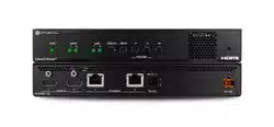
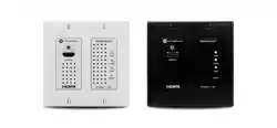
AT-OMNI-111/WP
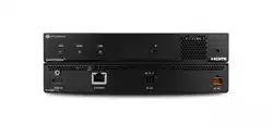
AT-OMNI-112
Using OmniStream
™
with
Velocity
™
Device Manager

Using OmniStream
™
with Velocity
™
Device Manager
2
Version Information
Version Release Date Notes
2 Aug 2024 Added documentation for OmniStream Virtual Matrix.
Using OmniStream
™
with Velocity
™
Device Manager
3
Sales, Marketing, and Customer Support
Operating Notes
Warranty
To view the product warranty, use the following link or QR code:
https://atlona.com/warranty/.
Main Oce
Atlona Incorporated
70 Daggett Drive
San Jose, CA 95134
United States
Oce: +1.408.962.0515
Sales and Customer Service Hours
Monday - Friday: 6:00 a.m. - 4:30 p.m. (PST)
https://atlona.com/
International Headquarters
Atlona International AG
Tdistrasse 18
8002 Zrich
Switzerland
Oce: +41.43.508.4321
Sales and Customer Service Hours
Monday - Friday: 09:00 - 17:00 (UTC +1)
IMPORTANT: Visit http://www.atlona.com/ for the latest rmware updates and User Manuals
for both OmniStream
™
and Velocity
™
Device Manager.

Using OmniStream
™
with Velocity
™
Device Manager
4
1. Read these instructions.
2. Keep these instructions.
3. Heed all warnings.
4. Follow all instructions.
5. Do not use this product near water.
6. Clean only with a dry cloth.
7. Do not block any ventilation openings. Install in
accordance with the manufacturer’s instructions.
8. Do not install or place this product near any heat
sources such as radiators, heat registers, stoves, or
other apparatus (including ampliers) that produce
heat.
9. Do not defeat the safety purpose of a polarized
or grounding-type plug. A polarized plug has two
blades with one wider than the other. A grounding
type plug has two blades and a third grounding
prong. The wide blade or the third prong are
provided for your safety. If the provided plug does
not t into your outlet, consult an electrician for
replacement of the obsolete outlet.
10. Protect the power cord from being walked on
or pinched particularly at plugs, convenience
receptacles, and the point where they exit from the
product.
11. Only use attachments/accessories specied by
Atlona.
12. To reduce the risk of electric shock and/or damage
to this product, never handle or touch this unit or
power cord if your hands are wet or damp. Do not
expose this product to rain or moisture.
13. Unplug this product during lightning storms or when
unused for long periods of time.
14. Refer all servicing to qualied service personnel.
Servicing is required when the product has been
damaged in any way, such as power-supply cord or
plug is damaged, liquid has been spilled or objects
have fallen into the product, the product has been
exposed to rain or moisture, does not operate
normally, or has been dropped.
CAUTION: TO REDUCT THE RISK OF
ELECTRIC SHOCK
DO NOT OPEN ENCLOSURE OR EXPOSE
TO RAIN OR MOISTURE.
NO USER-SERVICEABLE PARTS
INSIDE REFER SERVICING TO
QUALIFIED SERVICE PERSONNEL.
CAUTION
RISK OF ELECTRIC SHOCK
DO NOT OPEN
The exclamation point within an equilateral triangle is intended to alert the user to
the presence of important operating and maintenance instructions in the literature
accompanying the product.
The information bubble is intended to alert the user to helpful or optional opera-
tional instructions in the literature accompanying the product.
Safety and Certication
FCC Compliance
Copyright, Trademark, and Registration
FCC Compliance and Advisory Statement: This hardware device complies with Part 15 of the FCC rules. Operation is subject to the following two
conditions: 1) this device may not cause harmful interference, and 2) this device must accept any interference received including interference that
may cause undesired operation. This equipment has been tested and found to comply with the limits for a Class A digital device, pursuant to Part
15 of the FCC Rules. These limits are designed to provide reasonable protection against harmful interference in a commercial installation. This
equipment generates, uses, and can radiate radio frequency energy and, if not installed or used in accordance with the instructions, may cause
harmful interference to radio communications. However there is no guarantee that interference will not occur in a particular installation. If this
equipment does cause harmful interference to radio or television reception, which can be determined by turning the equipment o and on, the user
is encouraged to try to correct the interference by one or more of the following measures: 1) reorient or relocate the receiving antenna; 2) increase
the separation between the equipment and the receiver; 3) connect the equipment to an outlet on a circuit dierent from that to which the receiver
is connected; 4) consult the dealer or an experienced radio/TV technician for help. Any changes or modications not expressly approved by the
party responsible for compliance could void the user’s authority to operate the equipment. Where shielded interface cables have been provided
with the product or specied additional components or accessories elsewhere dened to be used with the installation of the product, they must be
used in order to ensure compliance with FCC regulations.
© 2024 Atlona Inc. All rights reserved. “Atlona” and the Atlona logo are registered trademarks of Atlona Inc. Pricing, specications and availability
subject to change without notice. Actual products, product images, and online product images may vary from images shown here.
Dolby, Dolby Atmos, and the double-D symbol are registered trademarks of Dolby Laboratories Licensing Corporation.
The terms HDMI, HDMI High-Denition Multimedia Interface, and the HDMI Logo are trademarks or registered trademarks of
HDMI licensing Administrator, Inc.
For DTS patents, see http://patents.dts.com. Manufactured under license from DTS, Inc. DTS, the Symbol, DTS and the Symbol together, and
Digital Surround are registered trademarks and/or trademarks of DTS, Inc. in the United States and/or other countries. © DTS, Inc. All Rights
Reserved.
All other trademark(s), copyright(s), and registered technologies mentioned in this document are the properties of their respective owner(s).

Using OmniStream
™
with Velocity
™
Device Manager
5
Introduction to OmniStream 8
OmniStream 101 8
IP Address Assignment 8
Network Bandwidth and OmniStream Compression 9
Streams 9
Sessions 9
Subscribing to a Stream 10
OmniStream Naming Schema 11
Getting Started 12
Accessing OmniStream Devices 12
Basic Conguration Tutorial 15
Physical Connections 15
Setting the System Mode 16
Conguring Inputs 17
Encoder Settings 19
Creating a Session 20
Subscribing to an Encoder 22
Video Conguration 22
Audio Conguration 23
Conguring the HDMI Output Stream 24
Troubleshooting 27
Encoder Checklist 27
Decoder Checklist 28
Device Operation 29
EDID Management 29
Selecting an EDID Preset 29
Adding a Custom EDID 30
Deleting a Custom EDID 31
Device Control 32
Downstream Control using RS-232 32
Control using TCP Proxy 36
Downstream Control using Triggering 37
Upstream Control using RS-232 42
Upstream Control using IR 45
Multiview Nomenclature 46
General Overview 46
Anchor Points 47
Multiview and Dual-Streaming Tutorial 48
Physical Connections 48
Dual-Streaming Encoder Conguration 49
Decoder Conguration 51
Multiview Conguration 52
Positioning Subframes 54
Changing the Background Color 54
Changing the Z-Order 55
Adding Subframes 56
Deleting a Subframe 56
Deleting a Multiview 56
Using Audio in Multiview 56
Conguring Audio Output 57
De-embedding Audio 57
Embedding Audio 57
Table of Contents

Using OmniStream
™
with Velocity
™
Device Manager
6
Table of Contents
Creating Video Walls 58
Creating Presets 61
Creating and Using Drop Zones 65
Custom Drop Zones 71
Conguring Redundant Streams 74
Redundancy Grace Period 74
AES67 Audio 75
Encoder Grouping 76
Daisy-Chaining Encoders 78
Scrambling 80
Fast Switching 81
Fast Switching FAQs 82
Slate / Logo Insertion 83
Adding Slates / Logos 83
Deleting Slates / Logos 86
Text Insertion 87
Conguring a Static IP Address 89
802.1X Authentication 91
The OmniStream Virtual Matrix 94
Launching the OmniStream Virtual Matrix 94
Layout and Operation 95
Icons and View Control 97
Options button 98
Flipping the Matrix 99
Legend 99
The Velocity Interface 100
Encoders 100
DEVICE INFO page 100
INPUT page 103
SERIAL page 107
SESSION page 109
NETWORK page 113
OTHER > LOGO page 115
OTHER > TEXT page 117
OTHER > PTP page 118
OTHER > LLDP page 119
CONFIGURATION page 120
HARDWARE INFO page 121
Decoders 122
DEVICE INFO page 122
IP INPUT page 125
MULTIVIEW page 126
SERIAL page 128
HDMI OUTPUT page 130
NETWORK page 135
OTHER > LOGO page 137
OTHER > TEXT page 139
OTHER > PTP page 140
OTHER > SAP page 141
OTHER > LLDP page 142
CONFIGURATION page 143
HARDWARE INFO page 144

Using OmniStream
™
with Velocity
™
Device Manager
7
Table of Contents
Appendix 145
Updating the Firmware 145
Performing a Link Test 147
Notes on Dual Streaming 149
Frequently Asked Questions 149
FEC Details 150
Matrix Size, Overhead, and Latency 150
FEC and Video Bitrate 150
FEC, Latency, and Lip Sync 151
Dierentiated Services Code Point 152
Using OmniStream
™
with Velocity
™
Device Manager
8
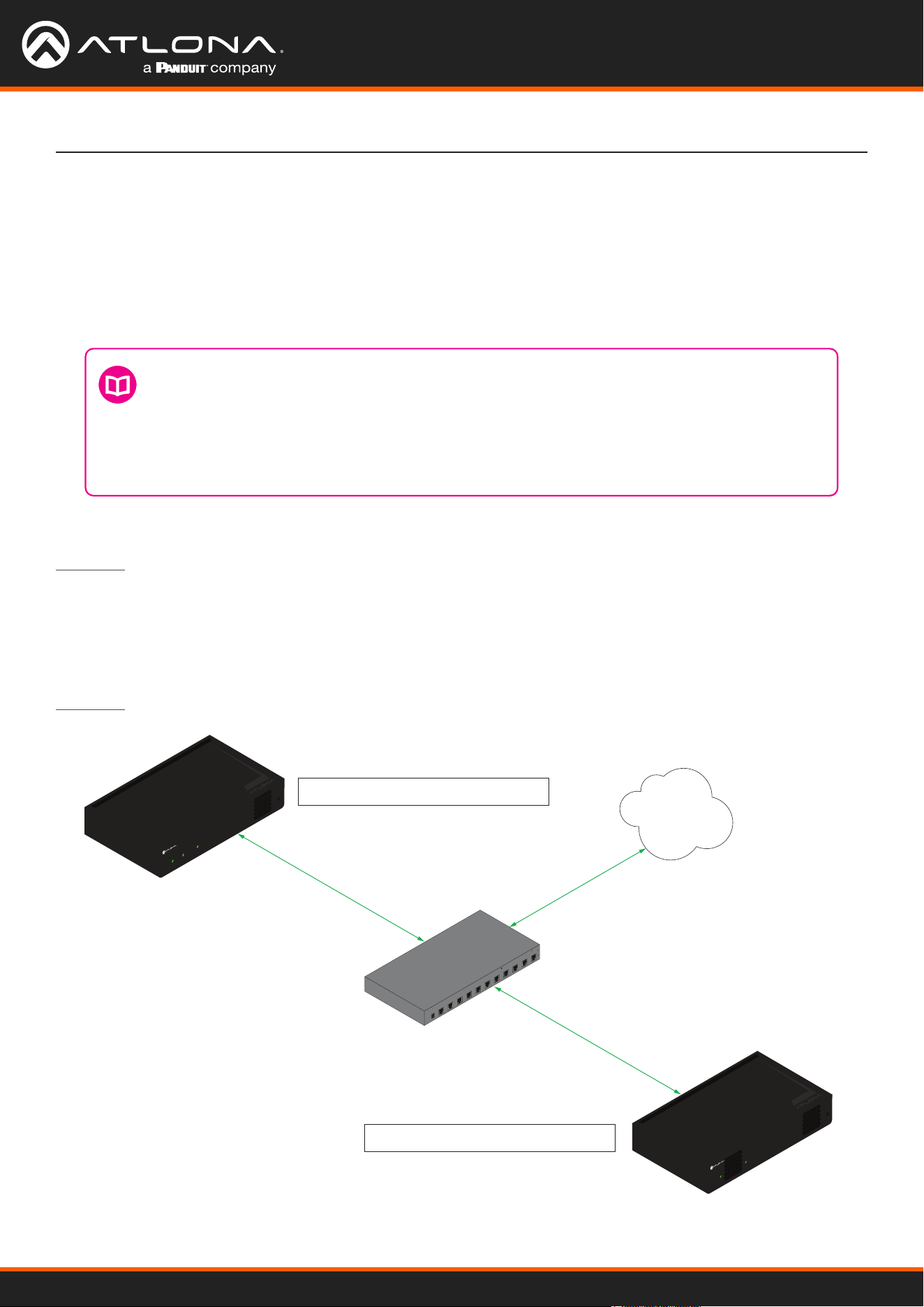
OmniStream products are similar in principle to matrix switch endpoints: A/V signals are sent from one point
(transmitter) to another point (receiver) over category cable. However, OmniStream stands apart from matrix
switchers, in that it is an IP-based solution, allowing this data to be sent over a standard IP network. In addition,
these endpoints are referred to as encoders and decoders. Encoders act as “transmitters” and decoders act as
“receivers”.
OmniStream 101
AT-OMNI-111
AT-OMNI-121
PoE Network Switch
Ethernet
Ethernet
HDMI
PWR
LINK
TM
O
MNI
S
TREAM
TM
O
MNI
S
TREAM
LINKPWR
LAN
Decoder IP Address: 192.168.1.38
Encoder IP Address: 192.168.1.27
IP Address Assignment
Figure 1.1 below, shows an encoder and a decoder, connected through a network switch. As with all network
devices, both the encoder and decoder must have unique IP addresses. OmniStream encoders and decoders are
DHCP-enabled, by default. This means that when the encoder/decoder is connected to the network, and a DHCP
server is available, the encoder/decoder will automatically be assigned an IP address. If no DHCP server is available,
then the unit will use a self-assigned IP address within the range of 169.254.xxx.xxx/16. OmniStream devices
can also be assigned a static IP address, if necessary. Static IP addressing will be covered in a later section.
Figure 1.1 - An encoder and decoder on a network, with assigned IP addresses.
DEFINITIONS
Encoder – Compresses source signals before sending them out over a network environment.
Decoder – Receives and decompresses signals from an encoder and sends them to an output
device, such as a display or other sink device.
IP Address – A unique numerical label that is assigned to each device connected to a network.
Introduction to OmniStream

Using OmniStream
™
with Velocity
™
Device Manager
9
Network Bandwidth and OmniStream Compression
When sending video and audio over a network, the available bandwidth needs to be managed. Gigabit Ethernet
switches are very common and can take advantage of installed Category 5e cable. 10-Gigabit Ethernet switches
are available, but are more expensive per port and require Category 6A cable or better. The chart below shows
uncompressed data rates for common resolutions. These data rates exceed the available bandwidth of Gigabit
Ethernet, but using the compression technology in OmniStream, this video can be streamed over cost-eective
Gigabit networks.
Resolution Data Rate*
1920 x 1080p 30 Hz 2.2 Gbps
1920 x 1080p 60 Hz 4.5 Gbps
3840 x 2160p 30 Hz 8.9 Gbps
3840 x 2160p 60 Hz 17.8 Gbps
OmniStream compresses the source data at the encoder, before it is sent out over the network. This process is
known as encoding. OmniStream uses VCx and VC-2 compression, which are intermediate compression schemes
and is much more desirable than using a interframe compression scheme, such as H.264 or H.265. Interframe
codecs are typically used by cable or internet providers and use very aggressive bit rates (low bandwidth) with high
latency (delay), which results in lag. VCx and VC-2 provide both high quality (high bit rates) and very low-latency for
a much more desirable viewing experience.
* Data rate is shown without compression.
Streams
Sessions
The term stream is used throughout this manual, to describe the dierent types of signals that are transmitted over a
network. For example, if a blu-ray player is connected to an encoder, both video and audio are sent to the encoder
over an HDMI cable. The term video stream is used to identify the video portion of a signal and audio stream
identies the audio portion of the signal.
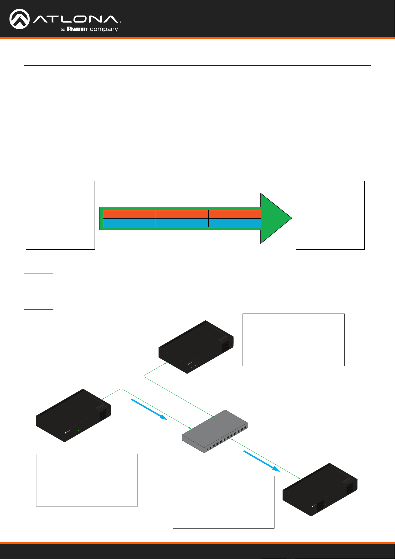
A session is a way of organizing audio and video streams. The session identies each stream with a unique multicast
IP address and UDP port assignment. This provides an address to determine where the package of audio and video
should be sent. Figure 1.2 illustrates how a session encapsulates a video and audio stream.
Figure 1.2 - Video and audio streams contained within a session.
UDP PortMulticast IP AddressVideo Stream
UDP PortMulticast IP AddressAudio Stream
Session
NOTE: Sessions are not limited to only video and audio streams. Control data, such as IR and
RS-232, as well as AES67 audio, can also be contained within a session. These topics will be
covered in a later chapter.
Introduction to OmniStream
Using OmniStream
™
with Velocity
™
Device Manager
10
Introduction to OmniStream
Subscribing to a Stream
To receive information from an encoder, the decoder must subscribe to the multicast IP address and UDP port of
the stream(s). Note that the decoder does not subscribe to the session, but to the stream(s) within the session.
The process of subscribing is similar to changing the channel on a Set-Top Box. For example, in order to view the
content on channel 213, the Set-Top Box must be set to channel 213. Similarly, for a decoder to subscribe to an
encoder stream, the multicast IP address and UDP port settings on the decoder must be set to the same values as
the encoder to which it is subscribed. Note that the management IP address of a unit is dierent than its multicast IP
address.
Figure 1.4 shows two encoders and a single decoder connected to a network switch. Decoder “C” is subscribed to
encoder “A”, since the multicast IP addresses and UDP port numbers for both video and audio are set to the same
values as encoder “A”.
Figure 1.3 - Diagram of a video and audio stream, transmitted over an Ethernet cable, to the subscribing decoder.
Video Data
Audio Stream
Video Stream Multicast IP: 226.0.0.1
Multicast IP: 226.0.10.1
UDP Port: 1000
UDP Port: 1100
Ethernet
Encoder
Video
Destination Multicast/Unicast Address
226.0.0.1
Destination UDP Port
1000
Audio
Destination Multicast/Unicast Address
226.0.10.1
Destination UDP Port
1100
Decoder
Video
Subscribed Multicast Address
226.0.0.1
Port
1000
Audio
Subscribed Multicast Address
226.0.10.1
Port
1100
AT-OMNI-111
AT-OMNI-121
PoE Network Switch
Ethernet
Stream
Ethernet
HDMI
PWR
LINK
TM
O
MNI
S
TREAM
AT-OMNI-111
HDMI
PWR
LINK
TM
O
MNI
S
TREAM
TM
O
MNI
S
TREAM
LINKPWR
Stream
Ethernet
A
B
C
Encoder IP Address: 192.168.1.27
Multicast IP Address (Video): 226.0.0.1
UDP Port (Video): 1000
Multicast IP Address (Audio): 226.0.10.1
UDP Port (Audio): 1100
Decoder IP Address: 192.168.1.38
Multicast IP Address (Video): 226.0.0.1
UDP Port (Video): 1000
Multicast IP Address (Audio): 226.0.10.1
UDP Port (Audio): 1100
Encoder IP Address: 192.168.1.98
Multicast IP Address (Video): 226.0.0.2
UDP Port (Video): 1000
Multicast IP Address (Audio): 226.0.10.2
UDP Port (Audio): 1100
Figure 1.4 - Decoder “C” subscribed to encoder “A”.

Using OmniStream
™
with Velocity
™
Device Manager
11
DEFINITIONS
Stream – Describes the video, audio, or any data that is transmitted from an encoder over the
network.
Multicast IP Address – A class-D IP address assigned to a stream.
UDP Port – User Datagram Protocol (UDP) port. Part of the network addressing scheme to send
and receive data to the proper destination on a network.
Subscribing – The process of selecting the multicast IP address to “listen to”, in order to receive
one or more encoder streams at the decoder endpoint.
Introduction to OmniStream
OmniStream Naming Schema
Each OmniStream model has a dierent set of inputs and outputs and, depending upon the number of inputs and
outputs. The number of supported session will depend upon the encoder model.
The last three numbers of the OmniStream SKU, describe the model version, model type, and number of outputs.
Note that the number of Ethernet outputs is the same as the number of HDMI inputs.
• AT-OMNI-112 1= OmniStream Pro (“R-Type” models begin with the number “5”).
1 = Indicates that the device is an encoder (decoders are identied with the number “2”).
2 = The number of Ethernet outputs.
Encoders Description
AT-OMNI-111
AT-OMNI-111-WP
• One HDMI input
• One Ethernet output
• Supports up to six sessions
AT-OMNI-112 • Two HDMI inputs
• Two Ethernet outputs
• Supports up to six sessions
AT-OMNI-512 • One HDMI input
• One Ethernet output
• Supports up to four sessions
Decoders Description
AT-OMNI-121 • One HDMI output
• One Ethernet output
AT-OMNI-122 • Two HDMI inputs
• Two Ethernet outputs
Using OmniStream
™
with Velocity
™
Device Manager
12
Accessing OmniStream Devices
The Velocity Device Manager uses multicast Domain Name Server (mDNS) to automatically discover each encoder
on the network.
By default, the OmniStream devices are set to DHCP mode, allowing a DHCP server (if present) to assign the
encoder an IP address. Once an IP address has been assigned, Velocity can be used to manage the product on the
network. Note that Velocity will only be able to discover encoders if they are on the same VLAN.
In order for Velocity to automatically assign multicast IP addresses to OmniStream devices, the destination IP
addresses for the session streams must be cleared.
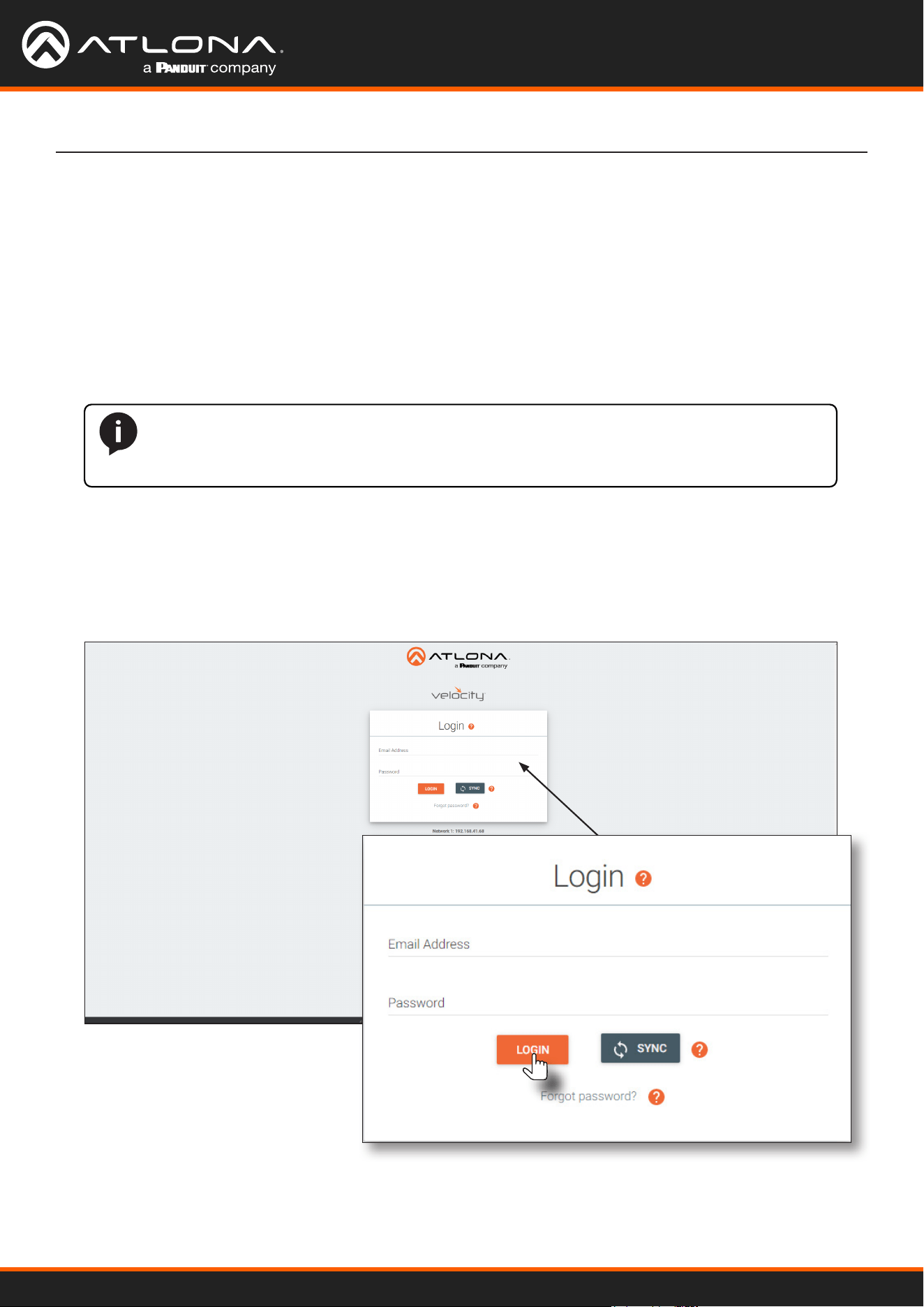
Getting Started
1. Launch a web browser and enter the IP address of Velocity, in the address bar.
2. Enter the required login credentials.
3. Click the LOGIN button.
NOTE: The following steps are required only if a pre-existing multicast IP address is
assigned to each session and if automatic assignment of these multicast IP addresses, using
Velocity, is desired.
Using OmniStream
™
with Velocity
™
Device Manager
13
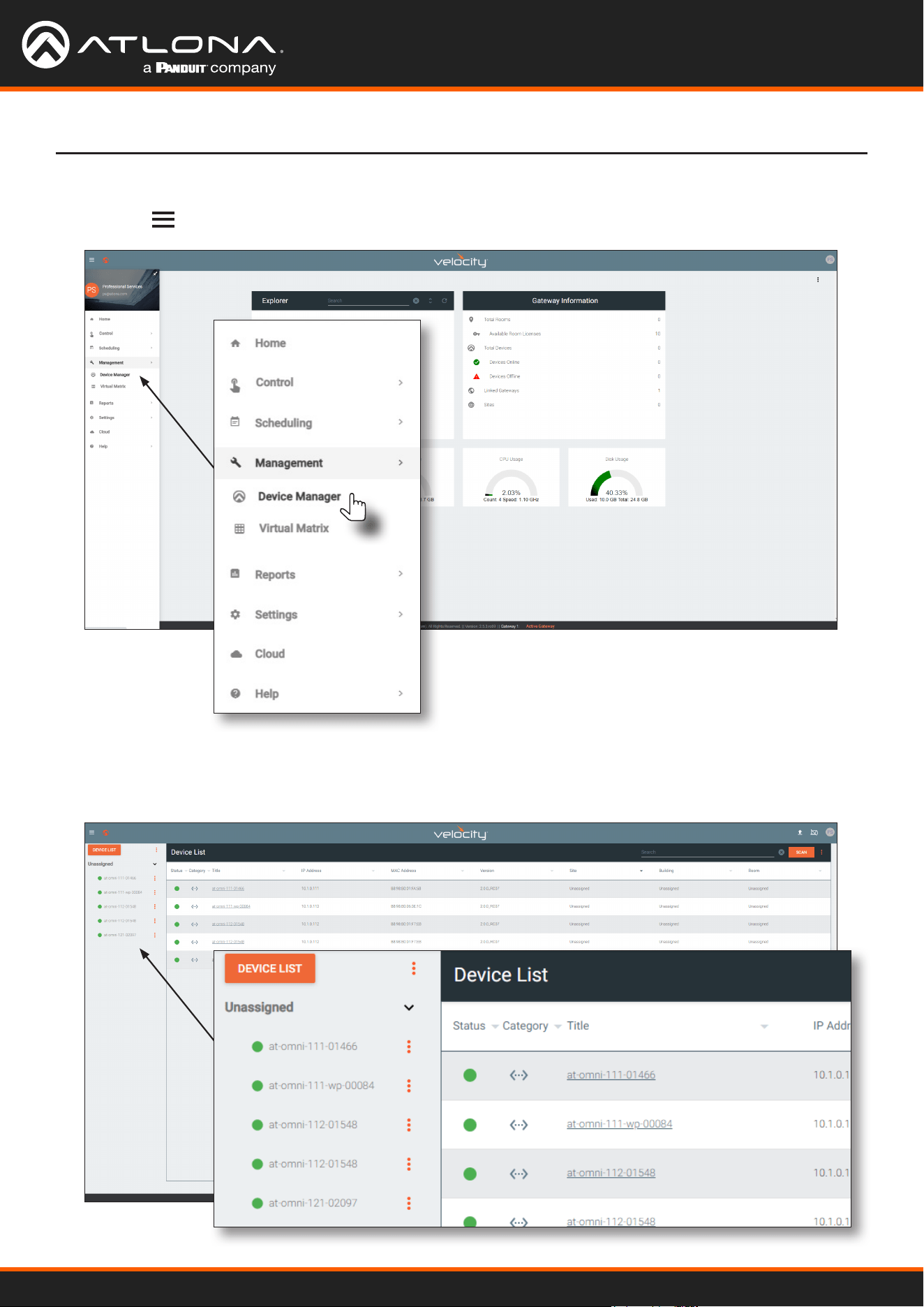
4. The Velocity home screen will be displayed.
5. Click the icon in the upper-left corner of the screen and select Management > Device Manager.
Getting Started
6. All available encoders will be displayed under the Unassigned category. When an encoder is unassigned, it
means that it has not been assigned to a site, building, and/or room. Refer to the Velocity User Manual for more
information on these topics.
Using OmniStream
™
with Velocity
™
Device Manager
14
Getting Started
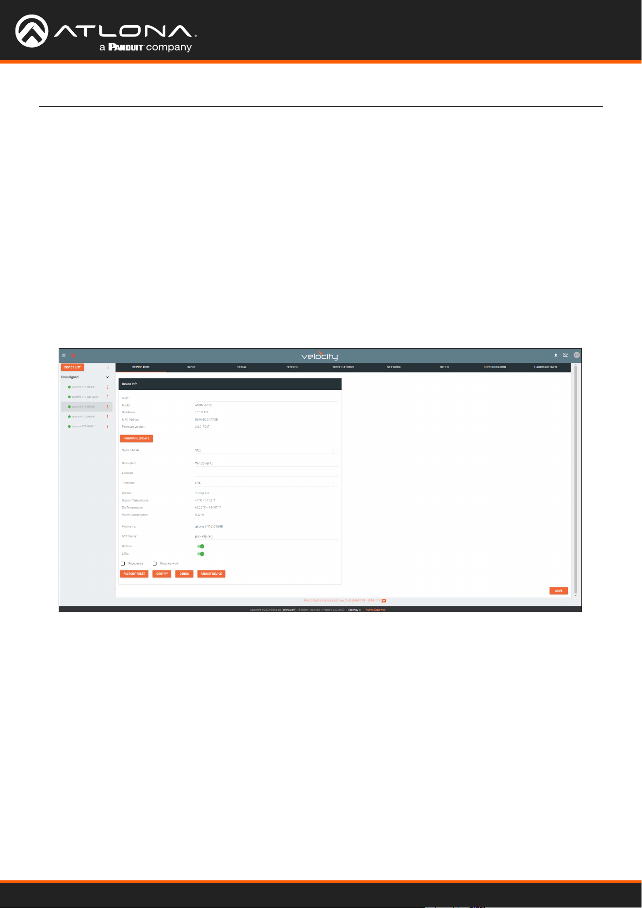
7. Click the desired OmniStream device from the Unassigned list.
8. The control interface for the device will be displayed and the device can be congured as desired.
The illustration below shows the DEVICE INFO screen for an AT-OMNI-112 encoder.
If a DHCP server is not found within 60 seconds, the encoder will be placed in Auto IP (APIPA) mode and
assigned an IP address within the range of 169.254.xxx.xxx/16. If this occurs, congure the network
interface of the computer that is running Velocity, located on the same subnet (169.254.xxx.xxx, subnet mask
255.255.0.0). Refer to Conguring a Static IP Address (page 89) for more information on conguring an
encoder in Auto IP mode.
If no OmniStream encoders are found, then verify the following:
• The computer that is running Velocity must be on the same network as the OmniStream device.
• Remove any network restrictions that may be in place. In order for mDNS to function properly, there
must not be any restrictions applied to the network.
Using OmniStream
™
with Velocity
™
Device Manager
15
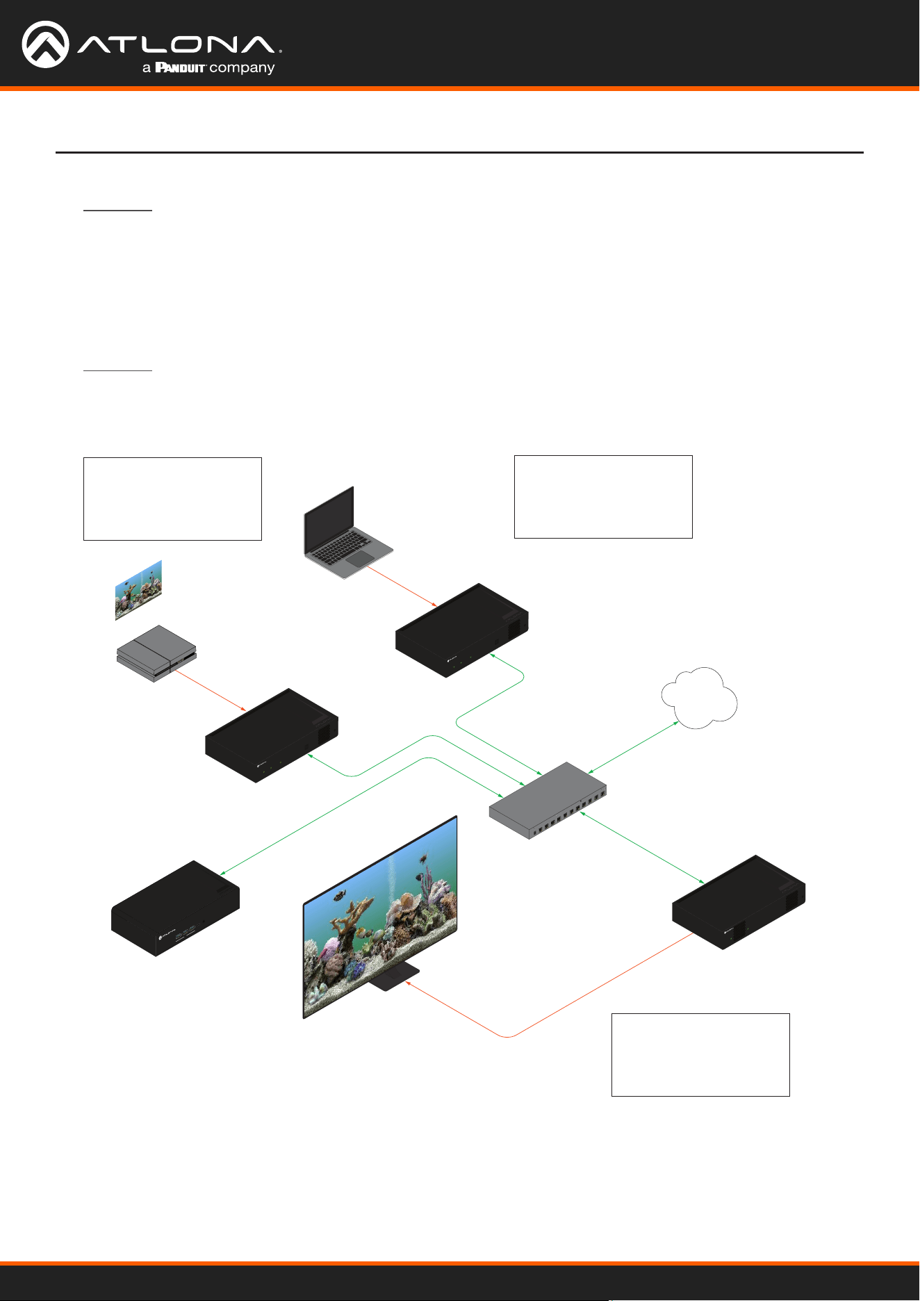
Basic Conguration Tutorial
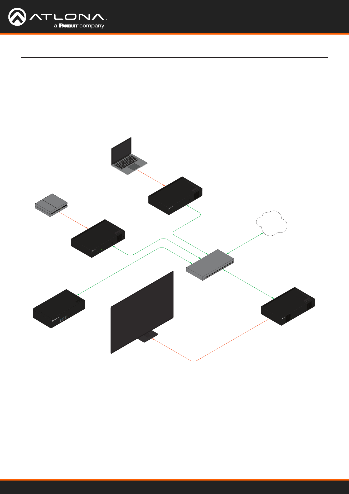
This section provides a tutorial on conguring two AT-OMNI-111 single-channel encoders and one AT-OMNI-121
single-channel decoder. Make sure the encoder is connected to a source device and that the decoder is connected
to a display. Both the encoder and decoder should be connected to the same local network.
Physical Connections
AT-OMNI-111
AT-VGW-HW
AT-OMNI-121
PoE Network Switch
Laptop
Display
Ethernet
Ethernet
Ethernet
Ethernet
Ethernet
HDMI IN
LAN
HDMI OUT
HDMI
PWR
LINK
TM
O
MNI
S
TREAM
ID
TM
O
MNI
S
TREAM
LINKPWR
AT-OMNI-111
HDMI IN
HDMI
PWR
LINK
TM
O
MNI
S
TREAM
ID
Gaming Console
Game Console
USB-C
AUDIO OUT
Velocity
TM
USB
USB
USB
USB
Encoder #1
Encoder #2
Decoder #1
Using OmniStream
™
with Velocity
™
Device Manager
16
OmniStream oers three system modes. These modes will optimize the video, based on the type of information that
is being displayed and/or the desired features.
Setting the System Mode
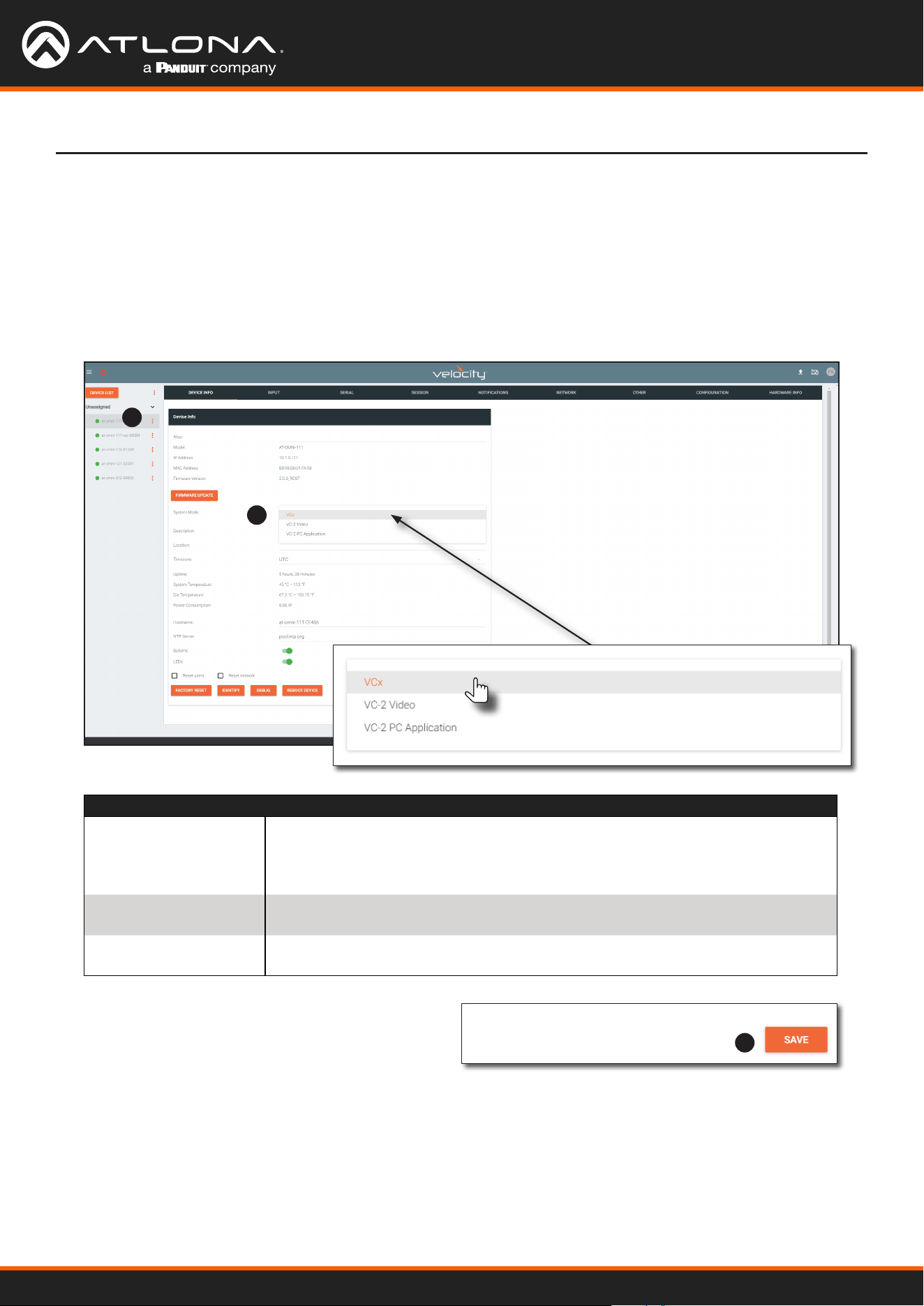
1. Under DEVICE LIST, select the encoder.
2. Click the System Mode drop-down list and select VCx. This mode will provide access to all of OmniStream 2.0
features.
1
2
3
3. Click SAVE in the bottom-right corner of the page to
commit changes.
4. Repeat this process for the other encoder and the
decoder.
Basic Conguration Tutorial
Mode Description
VCx
This is the default mode and represents the latest codec technology from Atlona,
with outstanding support for computer graphics and motion video. VCx includes
support for 4K60 4:4:4 fast switching, dual streaming from AT-OMNI-111
encoders, and multiview on the decoders.
VC-2 Video
Legacy OmniStream codec that provides the best viewing experience when
streaming motion graphics and/or video.
VC-2 PC
application
Legacy OmniStream codec that optimizes the image when viewing static
images, such as spreadsheets or similar content.
Using OmniStream
™
with Velocity
™
Device Manager
17
Conguring Inputs
The INPUT page is used to verify that the encoder recognizes the source device. This page is also used to set the
EDID, HDCP version, and provides detailed information about the source signal. The following procedure should be
performed on both AT-OMNI-111 encoders.
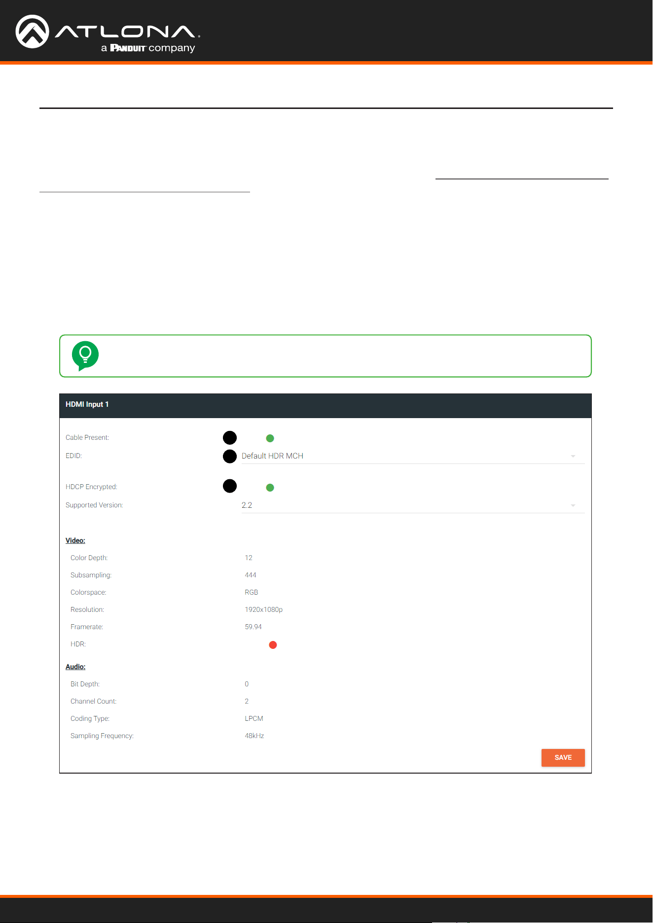
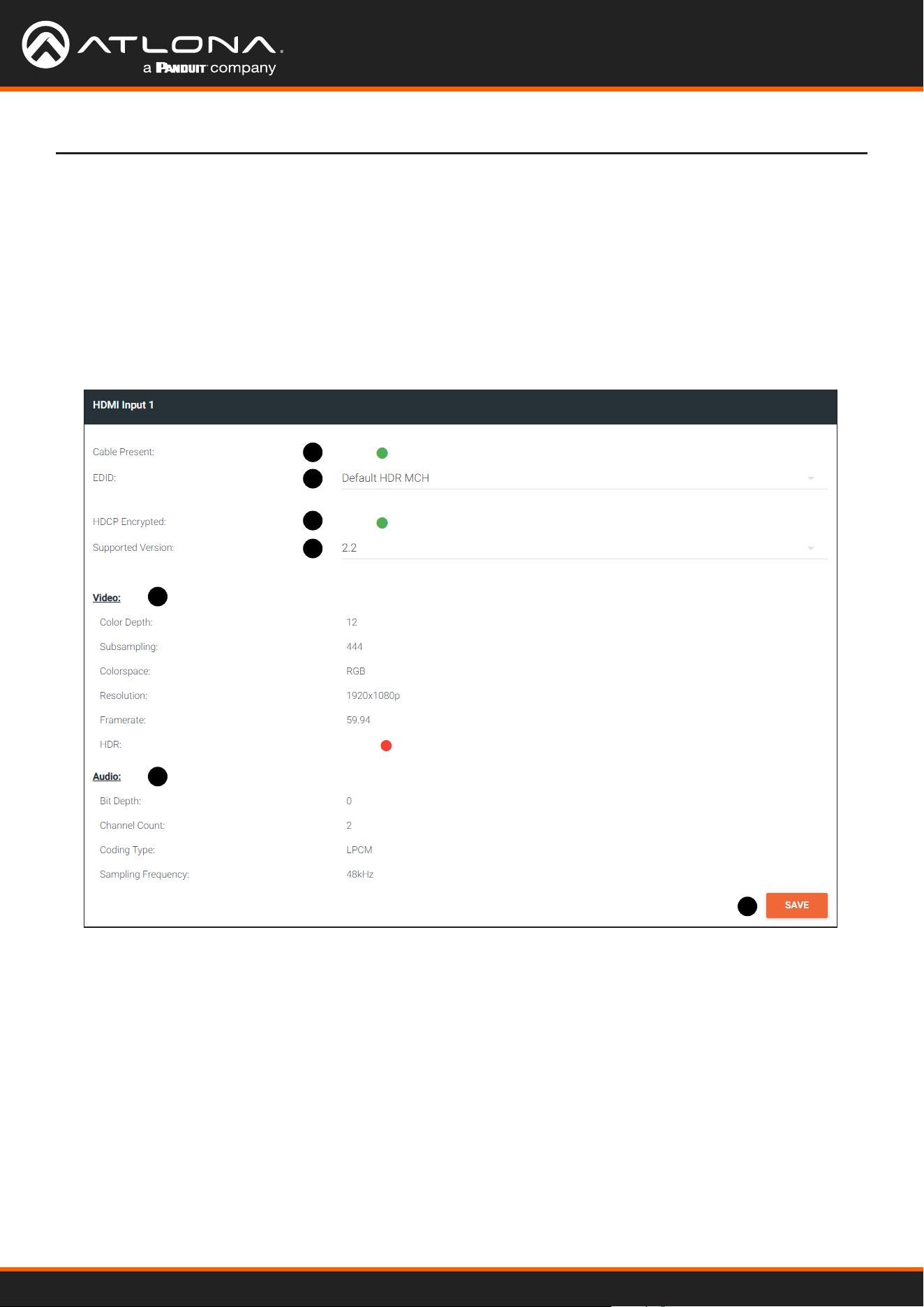
1. Click INPUT in the menu bar and locate the HDMI Input 1 window group. Since a source has been connected
to the HDMI IN port, the Cable Present indicator is green. This indicates that an active source is connected to
the HDMI port.
If these indicators are red, check that each source is connected to an HDMI IN port. A red indicator may also
describe faulty HDMI cables. If the sources are connected, then try dierent HDMI cables. If the HDMI cable
integrity has been veried, then make sure that the output resolution of the source is at least 720p.
TIP: If no signal is being received on the encoder, then it’s always a good practice to check the
INPUT page on the encoder when performing additional troubleshooting.
Basic Conguration Tutorial
1
2
3
2. Click the EDID drop-down list to select an EDID. For now, leave this setting at Default HDR MCH. This EDID
provides general compatibility with most displays.
3. The HDCP Encrypted indicator will be green if HDCP content is present. If the source connected to the HDMI
IN port was not transmitting HDCP content, then the indicator will be red.
Using OmniStream
™
with Velocity
™
Device Manager
18
1
2
3
4
5
6
7
Basic Conguration Tutorial
4. Click the HDCP > Version drop-down list to restrict HDCP to a particular version. By default, this is set to 2.2
and this setting should be used for most applications.
5. The Video section provides information about the input signal: color depth, subsampling, color space,
resolution, frame rate, and HDR (High Dynamic Range). If the HDR indicator is green, this will indicate that HDR
content is being transmitted from the source device. Refer to the INPUT page (page 103) for more information.
6. The Audio section displays audio information (if present) from the source device: bit depth, the number of audio
channels, the audio format, and the frequency. Refer to the INPUT page (page 103) for more information.
7. Click SAVE in the bottom-right corner of the HDMI Input 1 window group to commit changes.
Using OmniStream
™
with Velocity
™
Device Manager
19
Encoder Settings
Basic Conguration Tutorial
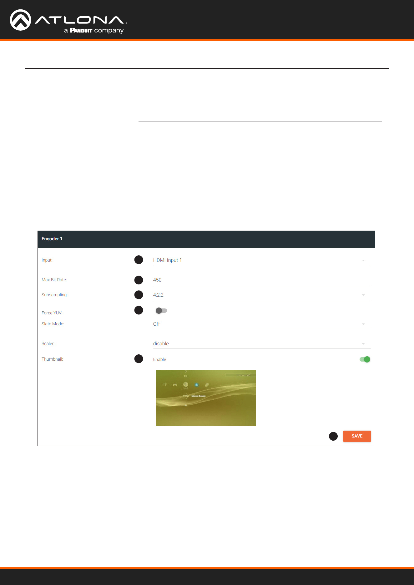
The INPUT page is also used to assign an input to an encoder. The Encoder window groups allow video settings,
such as the maximum bit rate, bit depth, and chroma subsampling to be set. Video thumbnails of the source device
can also be displayed on this page. The following procedure should be performed on both AT-OMNI-111 encoders.
1. Under the Encoder 1 window group, click the Input drop-down list and select HDMI Input 1.
2. Enter 750 in the Max Bit Rate eld. This means 750 Mbps. Bandwidth per port is calculated as 900 Mbps,
and on a dual-channel encoder, the combined bandwidth of both ports should not exceed 900 Mbps. So, if two
sources were connected to AT-OMNI-112 dual-channel encoder, then the Max Bit Rate eld for both Encoder 1
and Encoder 2 should not exceed a value of 450.
3. Click the Subsampling eld to set the chroma subsampling value. In this example it will be set to 4:2:2.
4. The Force YUV toggle switch can be set to on to force YUV color space. In this example, it will be disabled
(default). If enabled, the toggle switch will be green.
1
2
3
4
5
6
5. Click the Thumbnail > Enable toggle switch to enable it and display a thumbnail of the source. When enabled,
the toggle switch is green and a thumbnail of the source will be displayed. If no thumbnail is displayed when this
feature is enabled, verify that the source is connected and powered.
6. Click SAVE to commit all changes.
Using OmniStream
™
with Velocity
™
Device Manager
20
Basic Conguration Tutorial
Creating a Session
Before the video and audio (if any) can be sent out over the network, a session must be created on the encoder.
The session assigns each stream to a unique multicast IP address and UDP port assignment. Sessions are always
created on encoders. Refer to SESSION page (page 109) for a detailed description of all settings. The following
procedure should be performed on both AT-OMNI-111 encoders, except where noted.
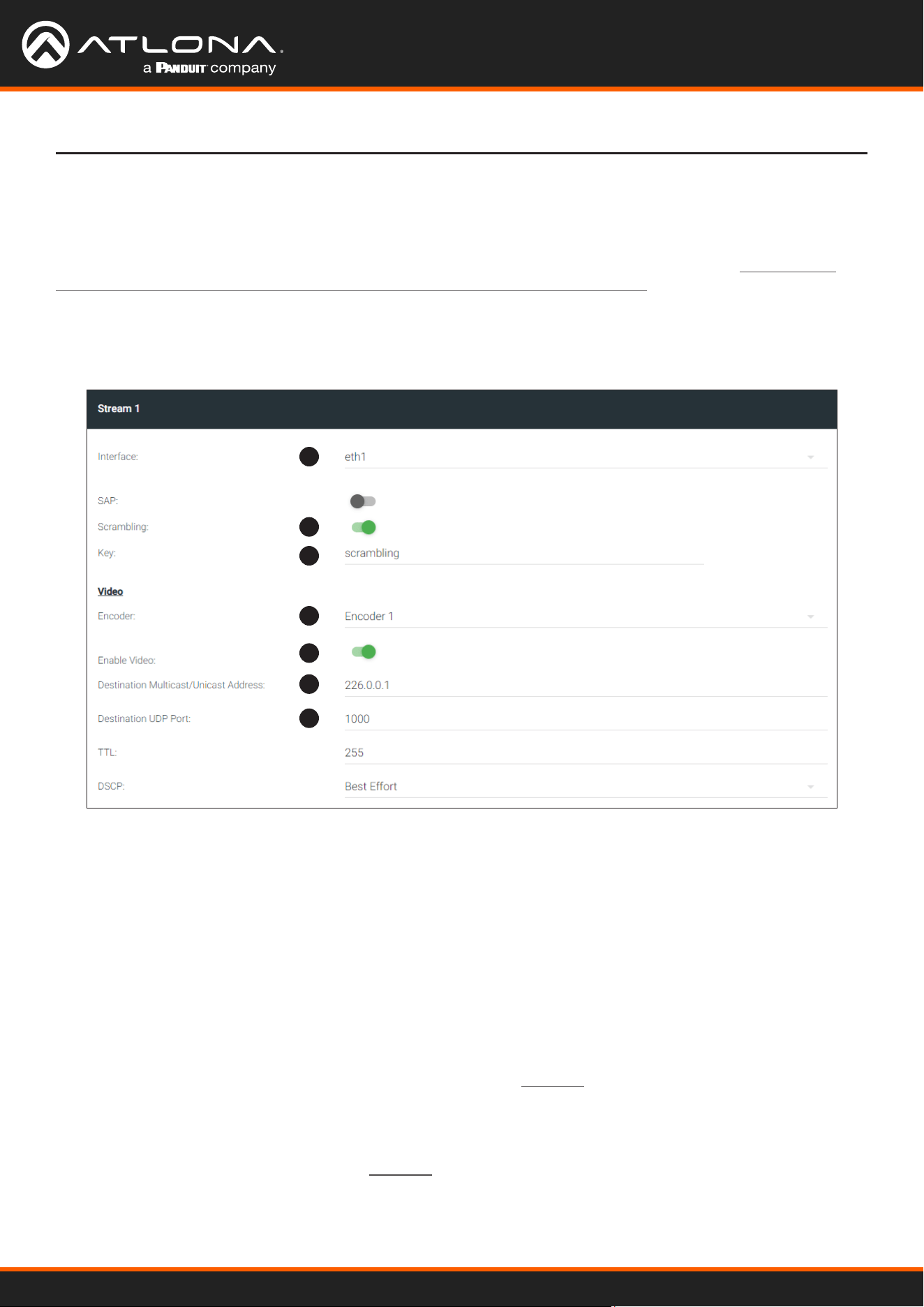
1. Click SESSION in the menu bar, locate Stream 1, and click the Interface drop-down list to select the desired
interface. This can be changed to eth1 or none. For this example, Stream 1 will be transmitted over the
ETHERNET 1 port. Therefore, set this to eth1.
2. The Scrambling toggle switch is enabled by default. When enabled, this toggle will be orange. Leave this setting
enabled.
3. The Key eld is set to scrambling by default. Scrambling keys can be any combination of alphanumeric
characters and it is good practice to use them. For this tutorial, use the default key.
4. Select the encoder for the video stream. In the last section, HDMI Input 1 was assigned to Encoder 1.
Therefore, set the Video > Encoder eld to Encoder 1.
5. Click the Video > Enable Video toggle switch and make sure it is enabled for Stream 1. When enabled, the
toggle switch will be green. If set to disabled, then the encoder video stream will be disabled.
6. Enter the multicast IP address for the video stream in the Video > Destination Multicast/Unicast Address eld.
Atlona recommends using multicast IP addresses, as shown in Table 1.1 on the next page. Enter 226.0.0.1 in
the Video > Destination Multicast/Unicast Address eld for Stream 1 on Encoder #1. For Encoder #2, enter
226.0.0.2 in the Video > Destination Multicast/Unicast Address eld for Stream 1.
7. Enter the UDP port in the Video > Destination UDP port eld. Although any valid UDP port can be used, Atlona
suggests using the UDP port numbers in Table 1.1, on the next page. Since this is a video stream, enter 1000 in
the Video > Destination UDP port eld for Stream 1.
1
2
3
4
5
6
7
Using OmniStream
™
with Velocity
™
Device Manager
21
Basic Conguration Tutorial
Stream Video Audio Data (Control)
UDP Port
1000 1100 1200
Table 1.2 - Recommended UDP ports for video, audio, and data streams.
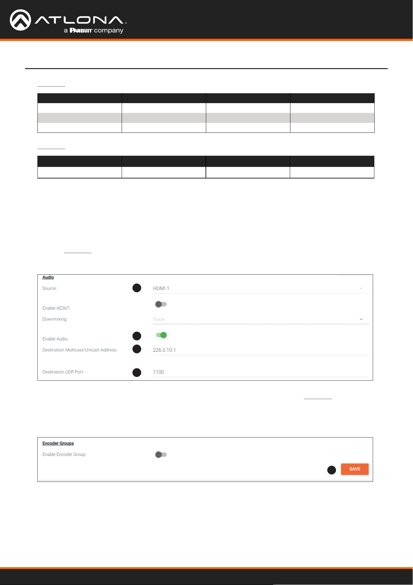
8. Click the Audio > Source drop-down list and select the HDMI audio input for the stream. The source is
connected to HDMI IN. Therefore, set this to HDMI 1.
9. Click the Audio > Enable toggle switch and make sure it is enabled. When enabled, it will be green. If disabled,
no audio will be streamed from the encoder.
10. Enter the multicast IP address for the audio stream in the Audio > Destination Multicast/Unicast Address eld.
Refer to Table 1.1, above. In this example, enter 226.0.10.1 for Stream 1 on Encoder #1. Enter 226.0.10.2
for Stream 1 on Encoder #2.
8
9
10
11
12
Table 1.1 - Recommended multicast IP address for video, audio, and data streams.
Stream Video Audio Data (Control)
First source
226.0.0.1 226.0.10.1 226.0.20.1
Second source
226.0.0.2 226.0.10.2 226.0.20.2
nth source
226.0.0.n 226.0.10.n 226.0.20.n
11. Enter the audio stream UDP port in the Audio > Destination UDP Port eld. Refer to Table 1.2, above. Since
this is an audio stream, use UDP port 1100.
12. Click the SAVE button to commit all changes to Stream 1.
Using OmniStream
™
with Velocity
™
Device Manager
22
Subscribing to an Encoder
The next step is to congure the decoder so that it is able to receive video, audio, and/or data (control) streams from
the encoder. This process is referred to as “subscribing to the encoder”.
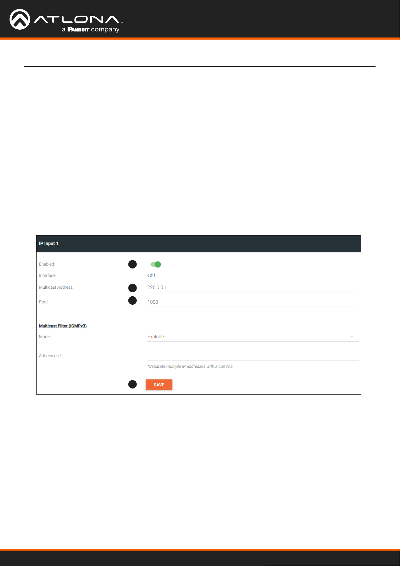
1. Go to the decoder, click IP INPUT in the menu bar, and locate the IP Input 1 window group. Verify that the
Enable toggle switch is enabled. When enabled, the toggle switch will be green. Perform the same procedure
for the IP Input 2 window group.
2. Under the IP Input 1 window group, enter 226.0.0.1 in the Multicast Address eld. Under the IP Input 2
window group, enter 226.0.0.2 in this eld. These multicast IP address are the same addresses that were
specied under the Video > Destination Multicast/Unicast Address eld for the encoders.
3. In the Port eld, enter 1000 under both IP Input 1 and IP Input 2 window groups. These are the same port
settings that were entered under the Video > Destination UDP Port eld of the encoder.
4. Click the SAVE button, under the IP Input 1 and IP Input 2 window groups, to commit changes.
Basic Conguration Tutorial
Video Conguration
1
2
3
4
Using OmniStream
™
with Velocity
™
Device Manager
23
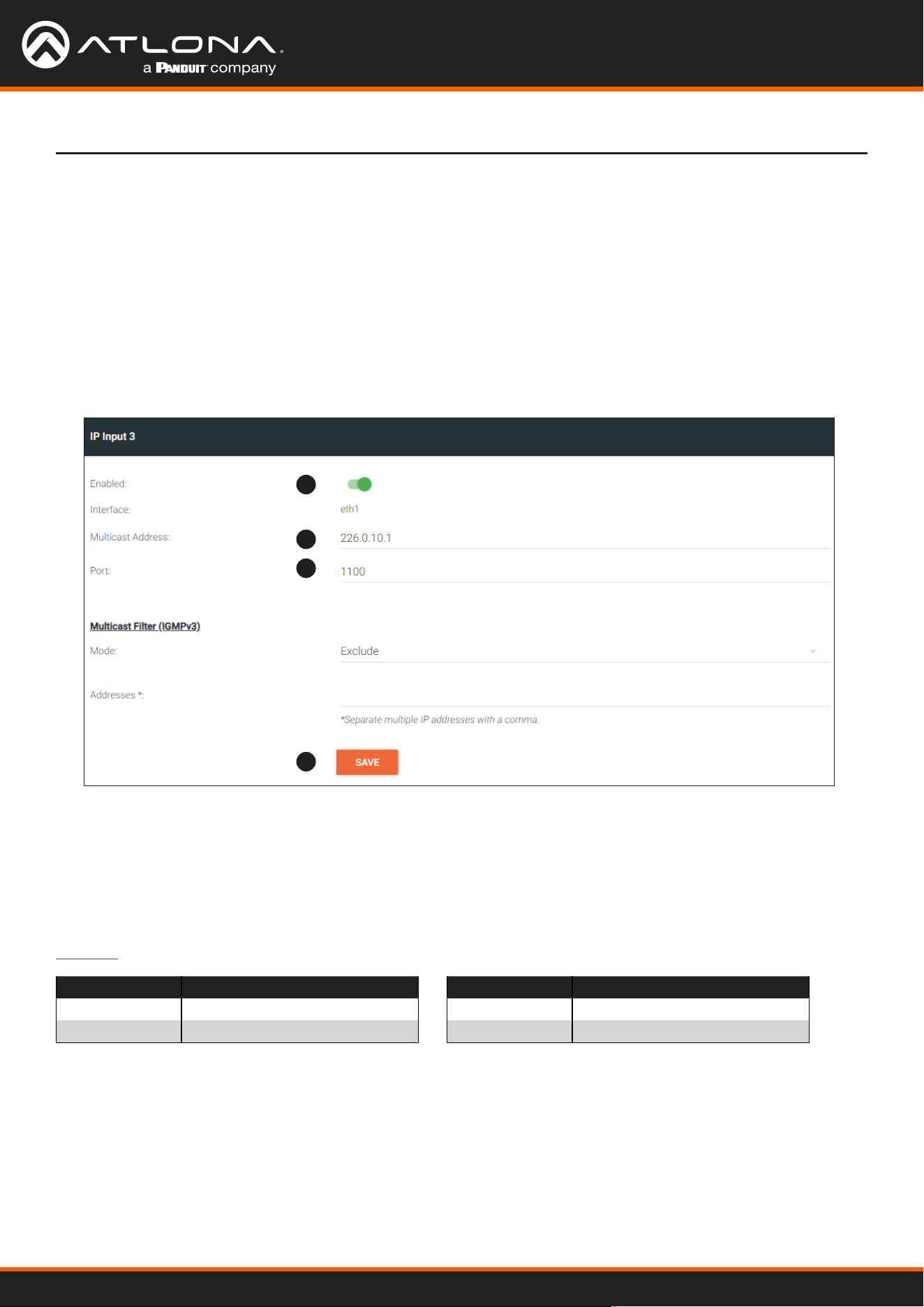
1. Locate the IP Input 3 window group and verify that the Enable toggle switch is enabled. When enabled, the
toggle switch will be green. Perform the same procedure for the IP Input 4 window group.
2. Under the Input 3 window group, enter 226.0.10.1 in the Multicast Address eld. Under the IP Input 4
window group, enter 226.0.10.2 in this eld. These multicast IP address are the same addresses that were
specied under the Audio > Destination Multicast/Unicast Address eld for the encoders.
3. In the Port eld, enter 1100 under both IP Input 3 and IP Input 4 window groups. These are the same port
settings that were entered under the Audio > Destination UDP Port eld for the encoders.
4. Click the SAVE button, under the IP Input 3 and IP Input 4 window groups to commit changes.
Audio Conguration
Basic Conguration Tutorial
1
2
3
4
Although there is no hard and fast rule for which IP Input window groups should be used for video, audio, and/or
control, it can be helpful to visualize the IP Input window groups as columns and rows to better organize the IP data.
The following tables were used to organize the data.
Input Conguration Notes
IP Input Encoder 1 Information
IP Input 1 Video (226.0.0.1:1000)
IP Input 3 Audio (226.0.10.1:1100)
IP Input Encoder 2 Information
IP Input 2 Video (226.0.0.2:1000)
IP Input 4 Audio (226.0.10.2:1100)
Table 1.3 - Video and Audio information for Encoder #1 and Encoder #2.
Using OmniStream
™
with Velocity
™
Device Manager
24
Basic Conguration Tutorial
Conguring the HDMI Output Stream
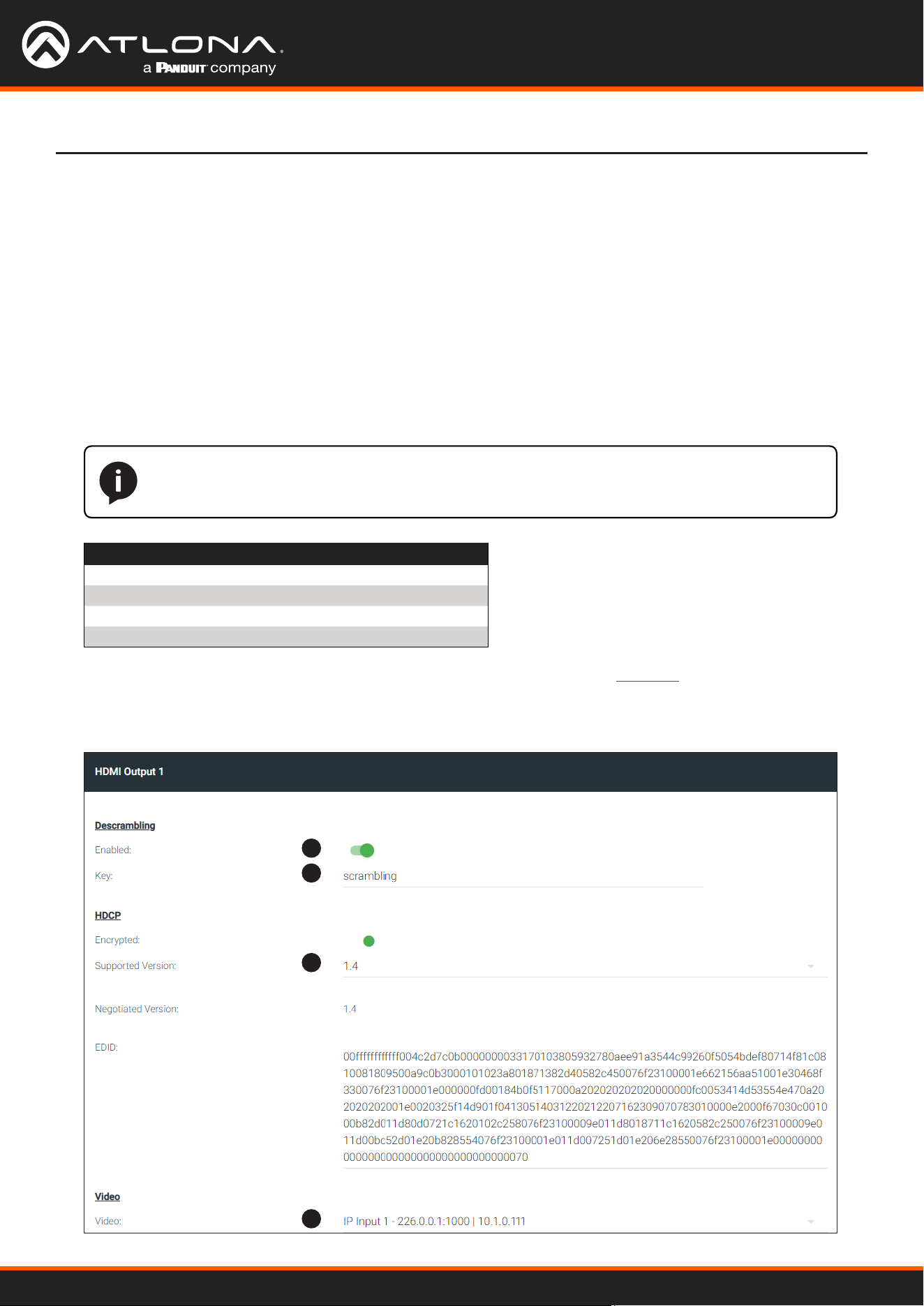
1. Click HDMI OUTPUT in the menu bar, locate the HDMI Output 1 window group, and verify that the
Descrambling > Enabled toggle switch is enabled. When enabled, this toggle will be green.
2. The Descrambling > Key eld is set to scrambling by default. This is the same key that is being used under
the Scrambling > Key eld on the encoder, and will allow the decoder to descramble the signal and send it out
over the HDMI output to the display. Leave this key at it’s default setting.
3. Click the HDCP > Supported Version drop-down list and select the HDCP version. 2.2 will work with most
sources. However, in this case, an older sink/monitor, which doesn’t support HDCP 2.2, is being used.
Therefore, the value is set to 1.4.
4. Click the Video > Video drop-down list and select the video source. Based on what has been congured, the
following options are available:
Video > Video
IP Input 1 - 226.0.0.1:1000 | 10.1.0.111
IP Input 2 - 226.0.0.2:1000 | 10.1.0.116
IP Input 3 - 226.0.10.1:1000 | 10.1.0.111
IP Input 4 - 226.0.10.2:1000 | 10.1.0.116
Since this is the Video eld, a video source should be selected. Referring to Table 1.3, on the previous page,
IP Input 1 - 226.0.0.1:1000 | 10.1.0.111 and IP Input 2 - 226.0.0.2:1000 | 10.1.0.116
are video data, from two dierent encoders. For this example, this eld will be set to IP Input 1 -
226.0.0.1:1000 | 10.1.0.111.
1
2
3
4
NOTE: The physical IP address of the OmniStream units that are listed in the table, below,
(10.1.0.111, etc.) may dier from the units that are connected to your network.
Using OmniStream
™
with Velocity
™
Device Manager
25
Basic Conguration Tutorial
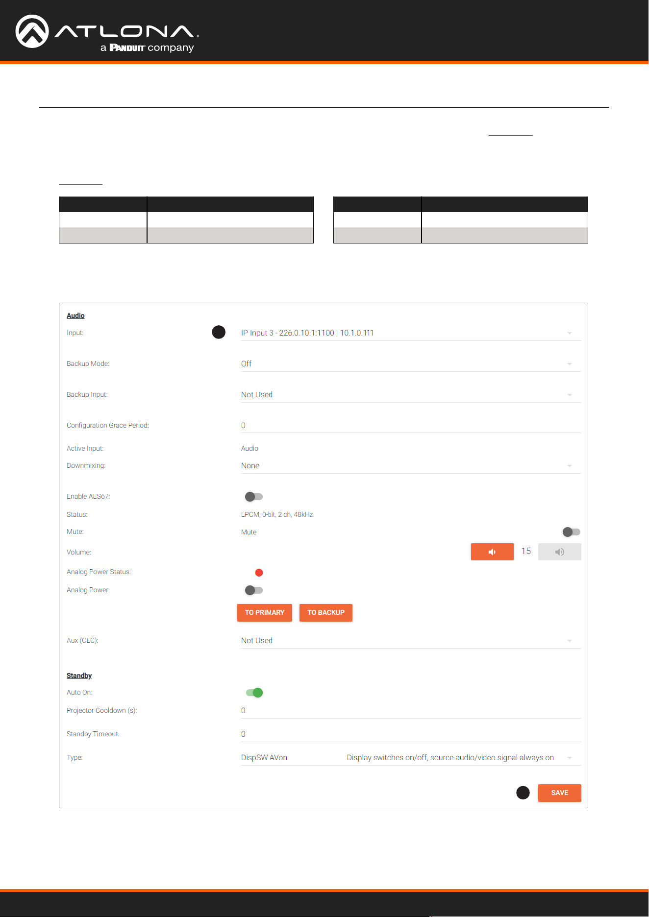
5. Scroll down to the Audio > Input eld and select the desired audio stream. Referring to Table 1.3 (shown below),
the audio stream that is associated with encoder 1 is Input 3. Therefore, IP Input 3 - 226.0.10.1:1000
| 10.1.0.111 is selected.
IP Input Encoder #1
Input 1 Video (226.0.0.1:1000)
Input 3 Audio (226.0.10.1:1100)
IP Input Encoder #2
Input 2 Video (226.0.0.2:1000)
Input 4 Audio (226.0.10.2:1100)
Table 1.3 - Video and Audio information for Encoder #1 and Encoder #2.
6. Click the SAVE button to commit changes.
5
6
Using OmniStream
™
with Velocity
™
Device Manager
26
AT-OMNI-111
AT-VGW-HW
AT-OMNI-121
PoE Network Switch
Laptop
Display
Ethernet
Ethernet
Ethernet
Ethernet
Ethernet
HDMI IN
LAN
HDMI OUT
HDMI
PWR
LINK
TM
O
MNI
S
TREAM
ID
TM
O
MNI
S
TREAM
LINKPWR
AT-OMNI-111
HDMI IN
HDMI
PWR
LINK
TM
O
MNI
S
TREAM
ID
Gaming Console
Game Console
USB-C
AUDIO OUT
Velocity
TM
USB
USB
USB
USB
The decoder should now display the content of the source device connected to HDMI IN on the encoder.
Figure 2.1 shows the completed conguration.
To switch between video sources, click the Video > Input drop-down list and select the desired stream.
To switch between audio streams, click the Audio > Input drop-down list to select the desired stream.
Note that separating video and audio data into dierent streams, allows the exibility of combining dierent video
and audio sources together.
Figure 2.1 - Basic OmniStream setup with a Decoder #1 subscribed to Encoder #1.
Stream 1
Stream 1
Destination IP Address (Video): 226.0.0.1
UDP Port (Video): 1000
Destination IP Address (Audio): 226.0.10.1
UDP Port (Audio): 1100
Destination IP Address (Video): 226.0.0.2
UDP Port (Video): 1000
Destination IP Address (Audio): 226.0.10.2
UDP Port (Audio): 1100
Encoder #1
Encoder #2
Basic Conguration Tutorial
HDMI Output
Destination IP Address (Video): 226.0.0.1
UDP Port (Video): 1000
Destination IP Address (Audio): 226.0.10.1
UDP Port (Audio): 1100
Decoder #1

Using OmniStream
™
with Velocity
™
Device Manager
27
• Very that all encoders and decoders are set to the same system mode. In this tutorial, both encoders and the
decoder should be set to VCx. Refer to Setting the System Mode (page 16).
• Go to the INPUT menu and verify the folllowing. Refer to Conguring Inputs (page 17) for more information.
» Make sure that the Cable Present indicator, under the HDMI Input 1 window group, is green.
» Make sure the Input drop-down list is assigned to an input. In this tutorial, the Input eld for both encoder 1
and encoder 2 are set to HDMI Input 1.
» Verify that the Max bit rate eld is set to at least 450.
» Verify that a Thumbnail > Enable toggle switch is enabled and a thumbnail of the source is displayed. When
enabled, the toggle switch will be green.
• Go to the SESSION menu and verify the following under the Stream 1 window group. Refer to Creating a
Session (page 20) for more information.
» Make sure the Interface eld for both encoders is set to eth1.
» Verify that the Encoder eld is set to Encoder 1.
» Check that the Scrambling toggle switch is enabled (green). Also check that the Key eld, for this example,
is set to scrambling for both encoders.
» Verify that the Video > Video Enable toggle switch is set to enabled for both encoders.
» Check the Video > Destination Multicast/Unicast Address eld is set to the correct multicast IP address.
In the example, 226.0.0.1. is used on encoder 1 and 226.0.0.2 is used on encoder 2.
» Check that the Video > Destination UDP Port eld is set to the proper port. In this example, 1000 should
be used on both encoders.
» Make sure the Audio > Source is set to HDMI 1 on both encoders.
» Verify that the Audio > Enable Audio toggle switch is enabled on both encoders.
» Check the Audio > Destination Multicast/Unicast Address eld is set to the correct multicast IP address.
In this example, 226.0.10.1 is used on encoder 1 and 226.0.10.2 is used on encoder 2.
» Check that the Audio > Destination UDP Port eld is set to the proper port. In this example, 1100 is used
for both encoders.
If no video and/or audio is present on the display, check the following:
Encoder Checklist
Basic Conguration Tutorial
Troubleshooting

Using OmniStream
™
with Velocity
™
Device Manager
28
Basic Conguration Tutorial
• Very that all encoders and decoders are set to the same system mode. In this tutorial, both encoders and the
decoder should be set to VCx. Refer to Setting the System Mode (page 16).
• Go to the IP INPUT menu and verify the following. Refer to Subscribing to an Encoder (page 22) for more
information.
» Under both the IP Input 1 and IP Input 2 window groups, verify that the Enabled toggle switch is enabled
(green).
» Check that the Multicast Address eld is set to the correct multicast IP address. In this example,
226.0.0.1 for IP Input 1 and 226.0.0.2 for IP Input 2.
» Check that the Port eld is set to the proper port. In this example, 1000 for both IP Input 1 and IP Input 2.
» Under both the IP Input 3 and IP Input 4 windows groups, verify that the Enabled toggle switch is enabled
(green).
» Check that the Multicast Address eld is set to the correct multicast IP address. In this example,
226.0.10.1 for IP Input 3 and 226.0.10.2 for IP Input 4.
» Check that the Port eld is set to the proper port. In this example, 1100 for both IP Input 3 and IP Input 4.
• Go to the HDMI OUTPUT menu and verify the following. Refer to Subscribing to an Encoder (page 22) for
more information.
» Make sure that the Descrambling > Enabled toggle switch is enabled (green).
» Verify that the Descrambling > Key eld matches the Scrambling > Key eld in the encoder. For this
tutorial, both of these elds should be set to scrambling.
IMPORTANT: The scrambling key on a decoder must be identical to the scrambling key on the
encoder which is being subscribed. Scrambling keys are case-sensitive.
Decoder Checklist
» Check the HDCP > Supported Version eld to make sure the correct version is selected. Also note the
color of the HDCP > Encrypted indicator. If it is red, then a picture may not be displayed and result in a
“blue screen” on the display. Change the HDCP > Supported Version eld, if necessary.
» Make sure that the Video > Video drop-down list is set to one of the congured video inputs: either IP
Input 1 - 226.0.0.1:1000 | 10.1.0.111 or Input 1 - 226.0.0.2:1000 | 10.1.0.116.
» Make sure that the Audio > Input drop-down list is set to one of the congured inputs: either IP Input 3
- 226.0.10.1:1000 | 10.1.0.111 or Input 4 - 226.0.10.2:1000 | 10.1.0.116.
Using OmniStream
™
with Velocity
™
Device Manager
29
EDID Management
OmniStream encoders provide EDID management for each input. The encoder can be assigned one of several
included EDID presets or can be assigned a custom EDID. Raw EDID data can be copied from displays or other sink
devices, that are connected to OmniStream decoders.
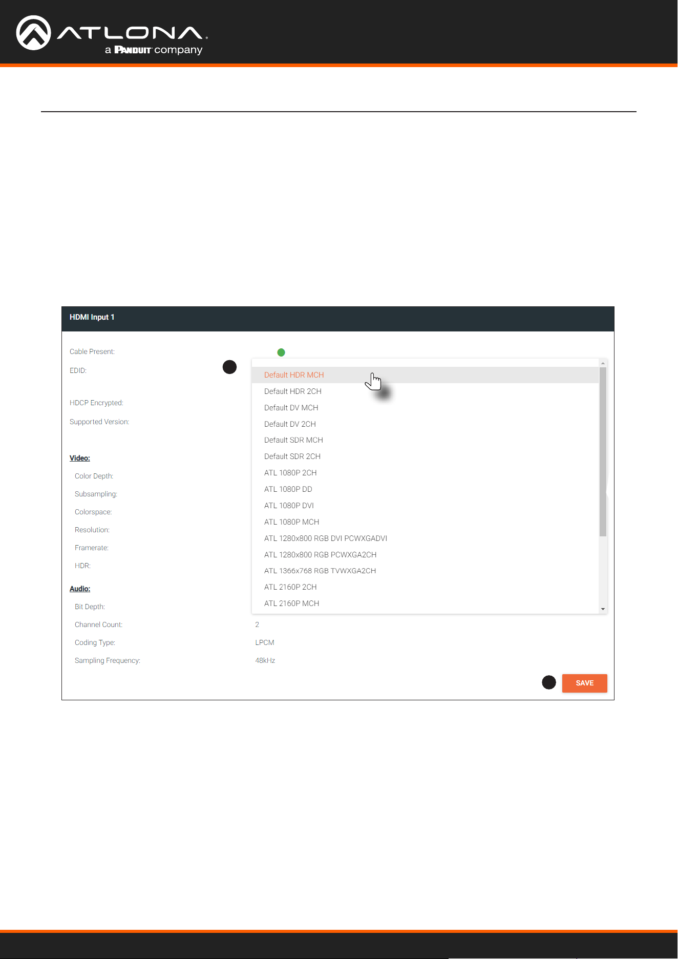
Selecting an EDID Preset
Device Operation
1
2
1. Go to the encoder, click INPUT in the menu bar, and click the EDID drop-down list to select the desired EDID.
2. Click the SAVE button within the HDMI Input window group to commit changes.
Using OmniStream
™
with Velocity
™
Device Manager
30
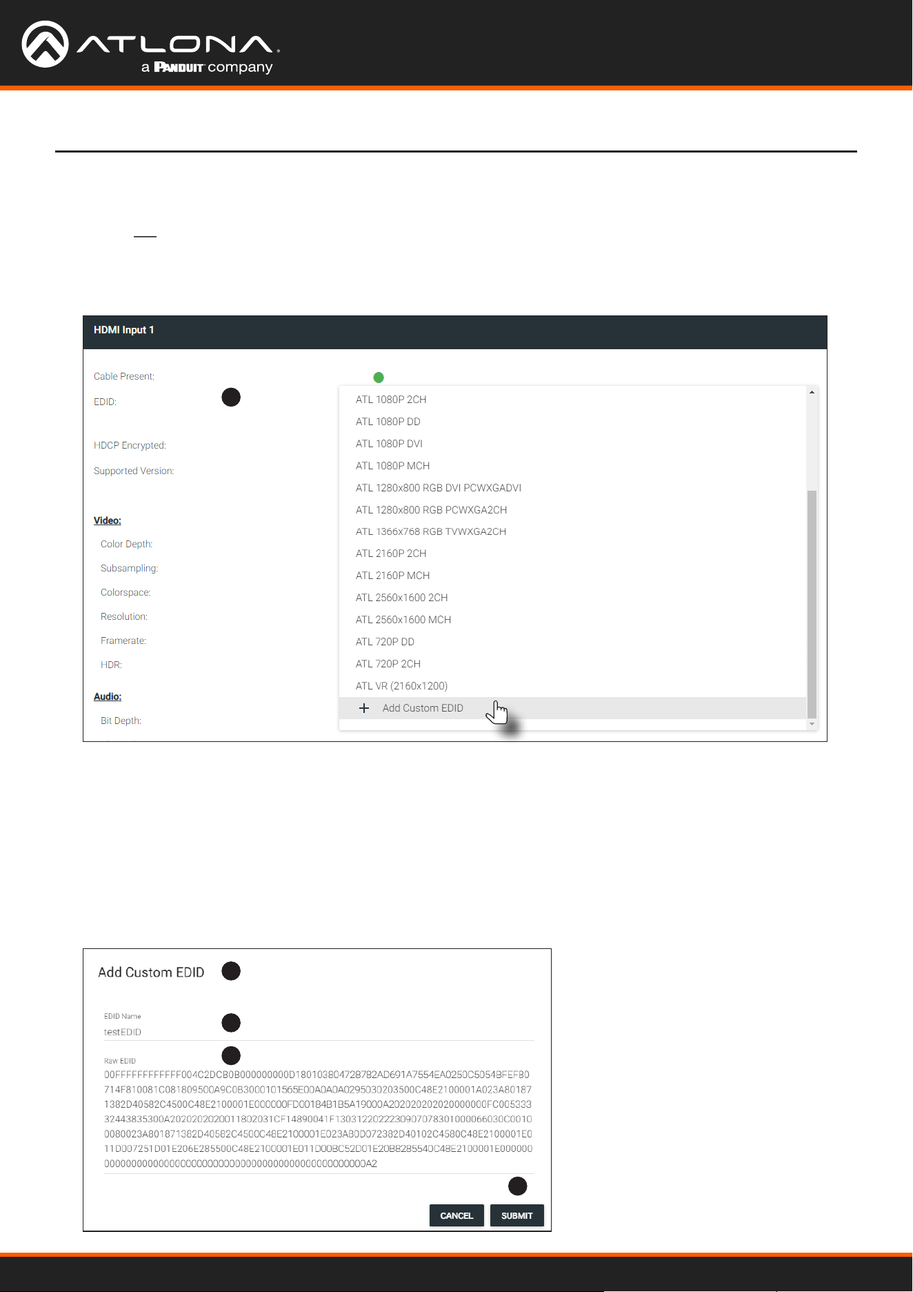
1. Click the INPUT menu. Click the EDID drop-down list, within the desired Input window group, and select the
Add Custom EDID.
1
2
3
4
5
2. The Add Custom EDID dialog will be displayed.
3. Enter the name of the EDID in the Name eld.
4. Enter the EDID data in the Raw EDID eld. EDID data must be in hexadecimal format and must not contain any
spaces or delimters.
5. Click the SUBMIT button to commit changes or click CANCEL to abort the addition of a custom EDID.
Once a custom EDID is created, it will be added to the drop-down list and can be selected without re-entering
the information.
Device Operation
Adding a Custom EDID
Encoders can be loaded with a custom EDID. The raw EDID data must be in hexadecimal format. Commas or
spaces are not permitted.
Using OmniStream
™
with Velocity
™
Device Manager
31
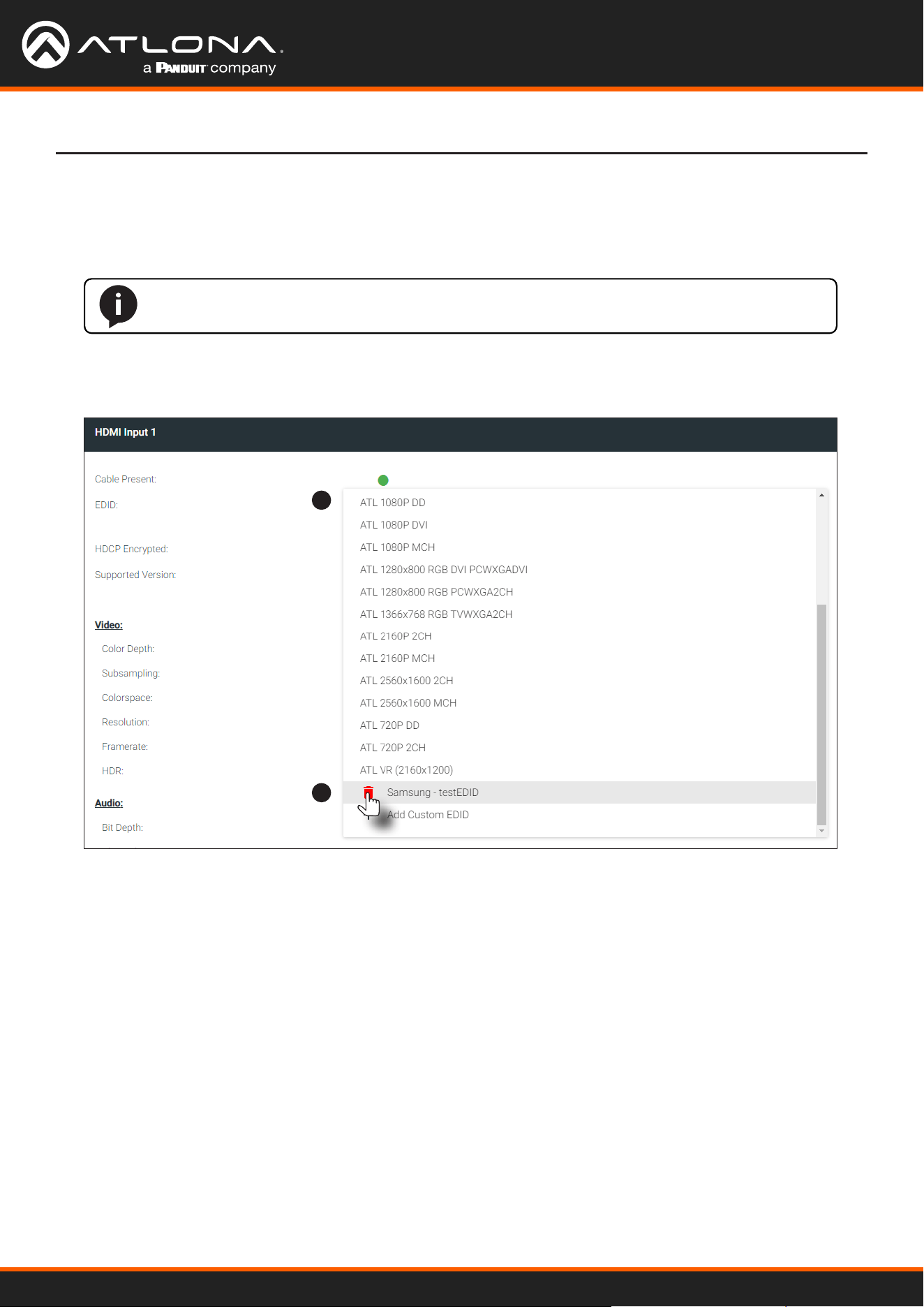
1. Click INPUT in the menu bar and click the EDID drop-down list, within the desired Input window group, and
select the EDID to be deleted.
Deleting a Custom EDID
Device Operation
NOTE: Only custom EDID data can be added or deleted. EDID presets cannot be modied.
2. Click the red “trash can” icon next to the EDID to be deleted. Once deleted, the page will refresh, and the EDID
will no longer be listed in the EDID drop-down list.
1
2
Using OmniStream
™
with Velocity
™
Device Manager
32
Device Control
Control using RS-232 is converted and transmitted over IP by the encoder. Destination devices can either be the IP
address of a display or a decoder.
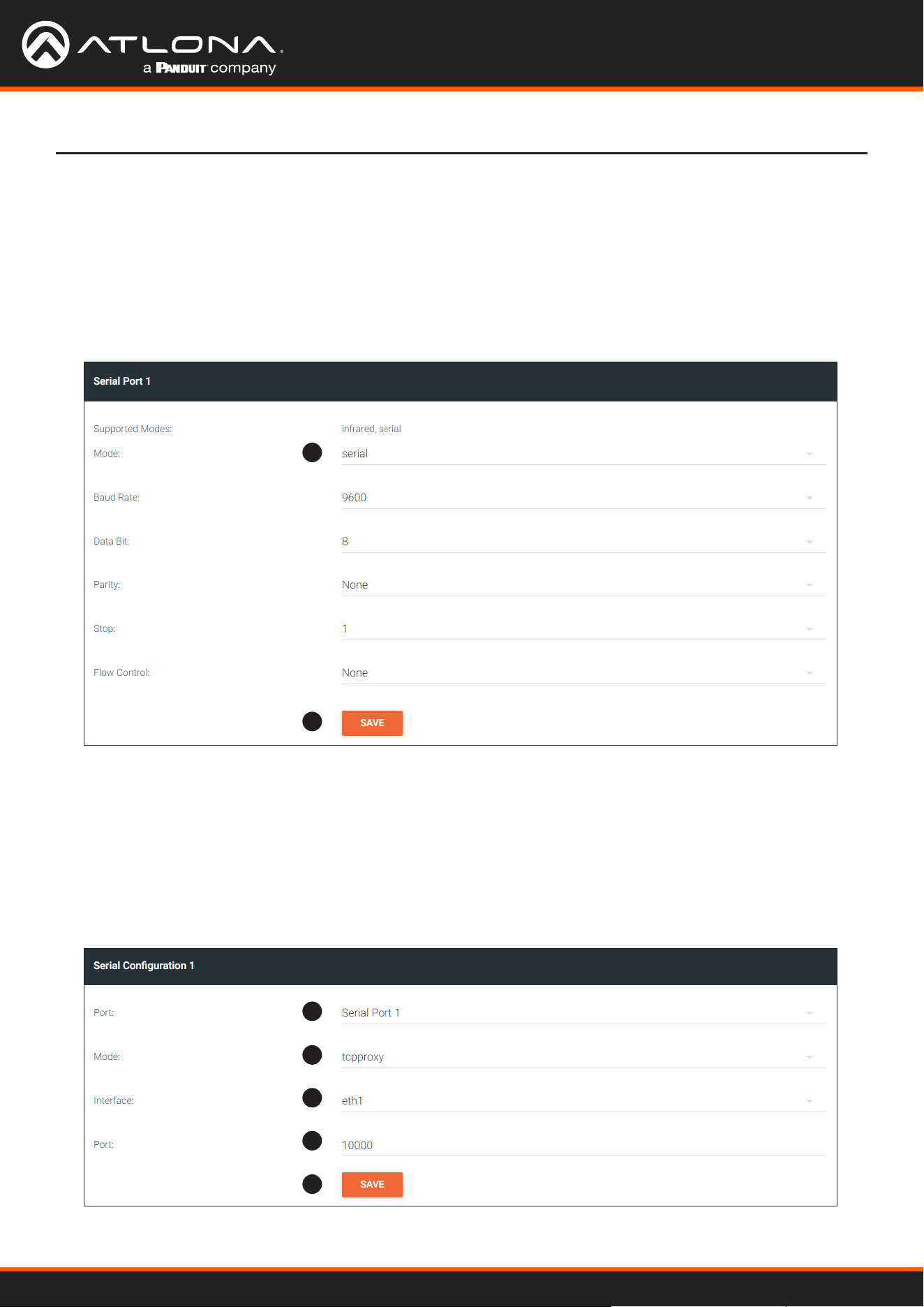
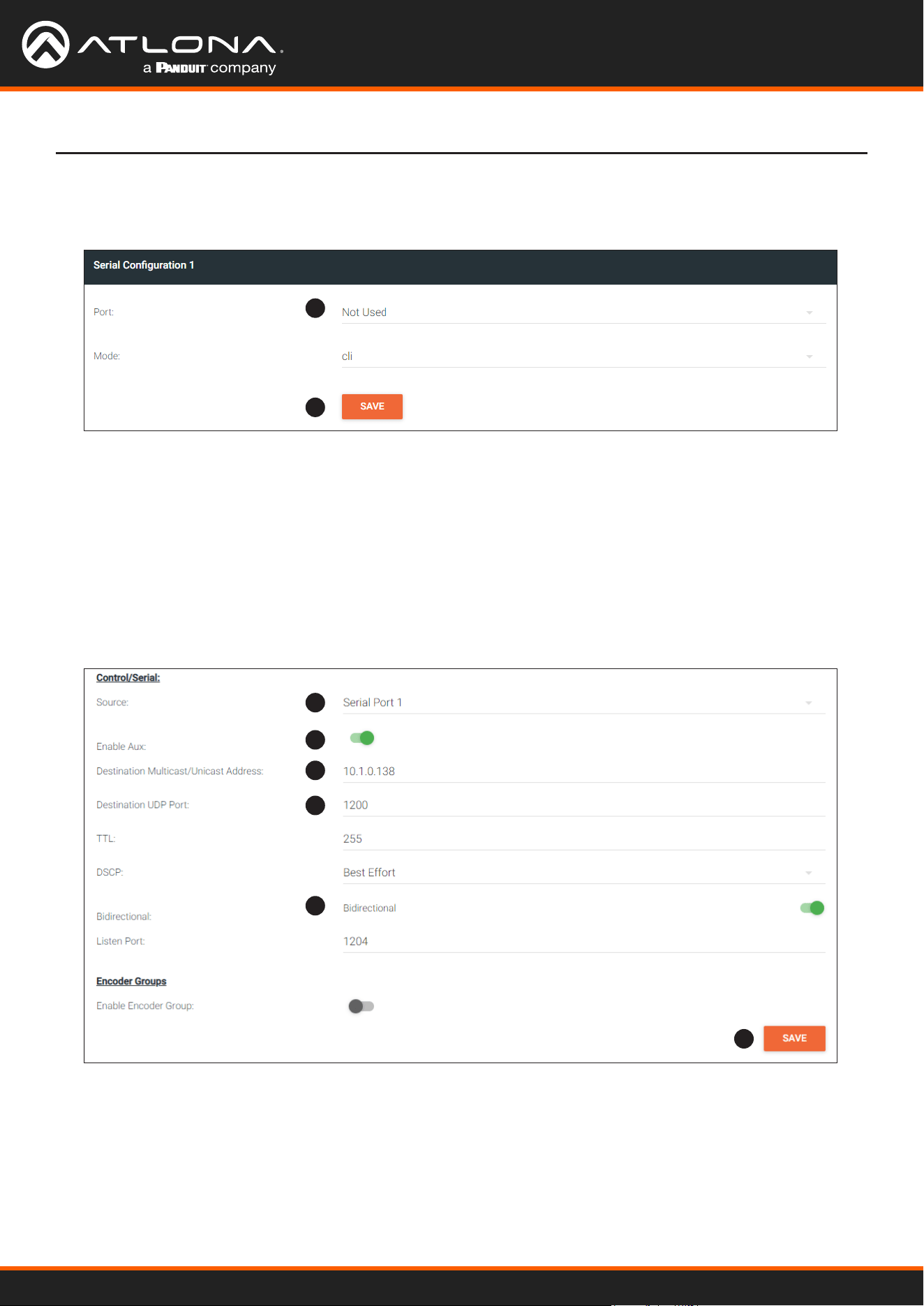
Downstream Control using RS-232
Device Operation
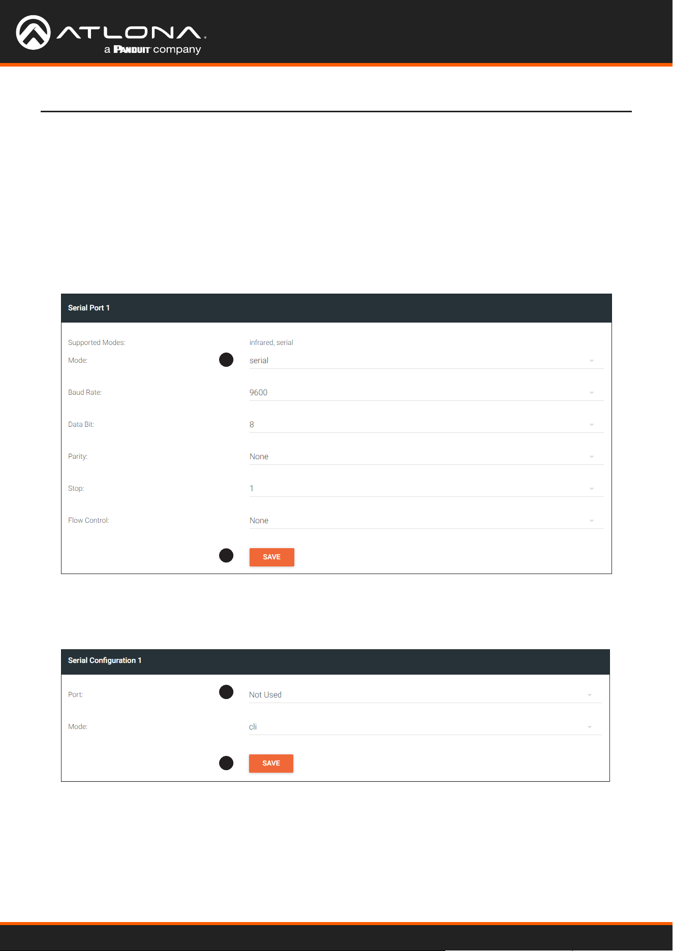
1. Login to the encoder and click the SERIAL menu. Under the Serial Port 1 window group, click the Mode drop-
down list and select Serial.
2. Click the SAVE button.
3. Under the Serial Conguration 1 window group, click the Port drop-down list and select Not Used.
4. Click the SAVE button.
1
2
3
4
Using OmniStream
™
with Velocity
™
Device Manager
33
Device Operation
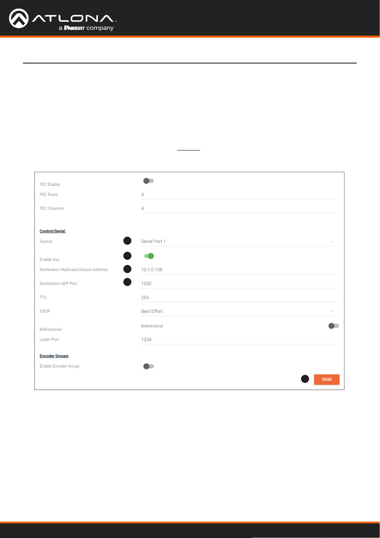
5. Click the SESSION menu. Under the desired stream, locate the Control/Serial section and click the Source
drop-down list to select the desired serial port.
6. Click the Enable Aux toggle switch to display the additional elds.
7. Enter the destination IP address and UDP port in the Destination Multicast/Unicast Address and Destination
UDP Port elds, respectively.
8. Click the SAVE button.
If the destination IP address and UDP port is for a decoder, follow Steps 9 through 20, beginning on the next
page.
5
6
7
7
8
Using OmniStream
™
with Velocity
™
Device Manager
34
Device Operation
9
10
11
12
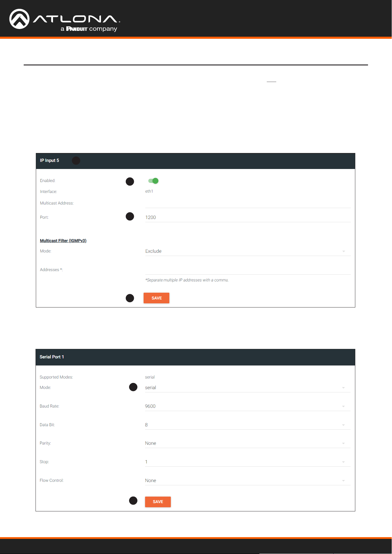
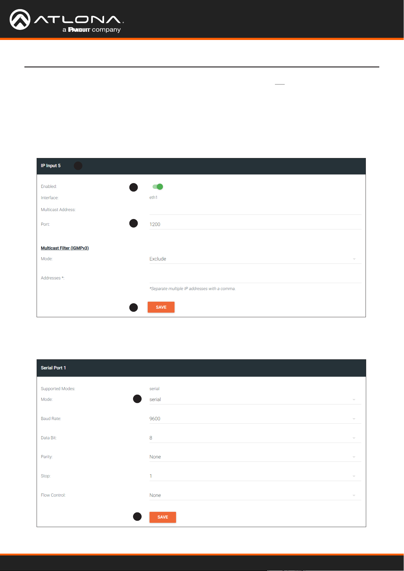
9. Login to the decoder and click the IP INPUT menu. Locate an Input that does not contain a dened Multicast
Address eld. In this example, Input 5 will be used. Note that if a multicast address was used in Step 7, then
that multicast address must be entered in the Multicast Address eld under Input 5.
10. Click the Enable toggle switch to enable the Input. When an Input is enabled, the toggle switch will be green.
11. Enter the UDP port, from Step 9, in the Port eld.
12. Click the SAVE button.
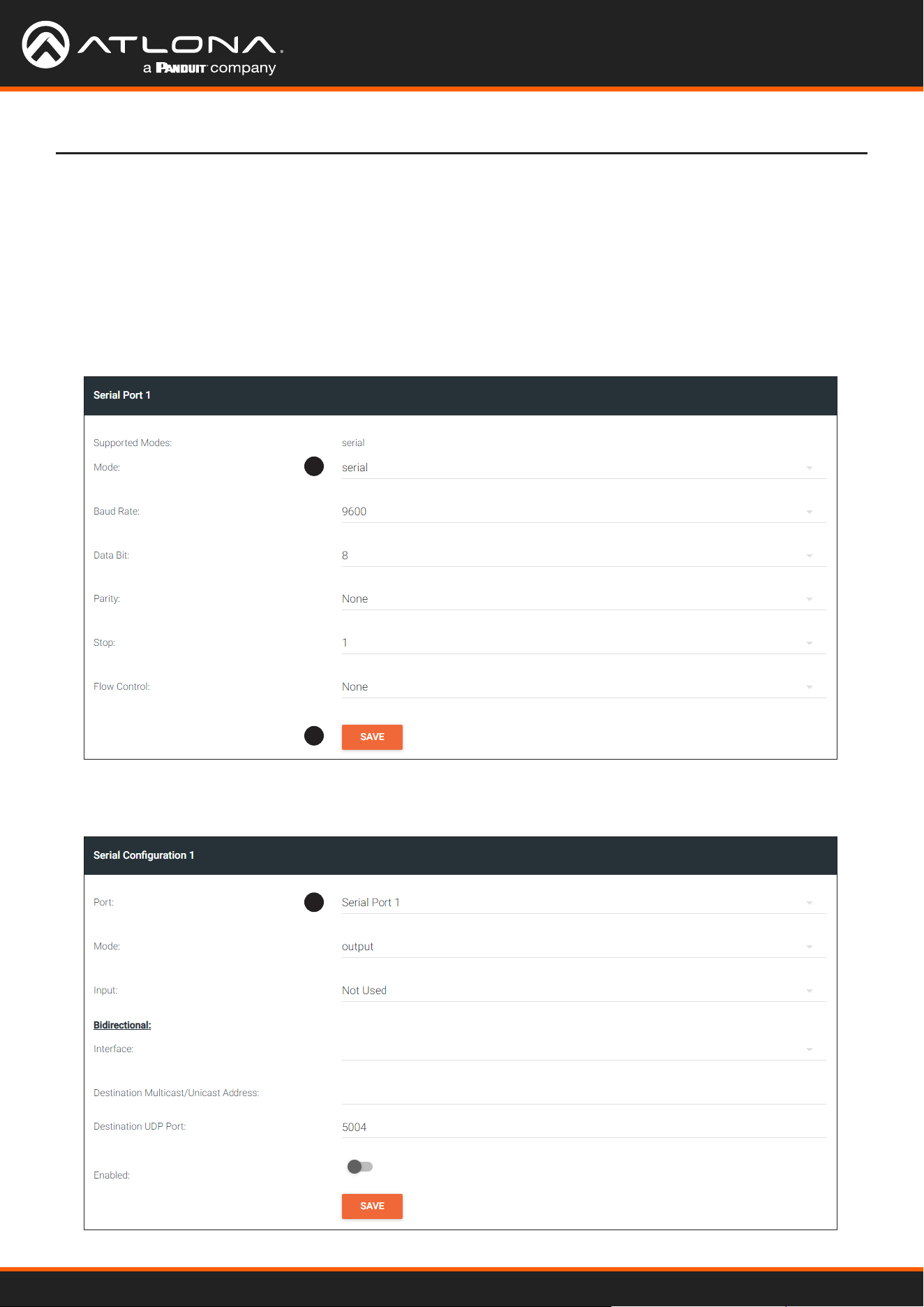
13. Click the SERIAL menu, and under Serial Port 1, click the Mode drop-down list and select serial.
14. Click the SAVE button.
13
14
Using OmniStream
™
with Velocity
™
Device Manager
35
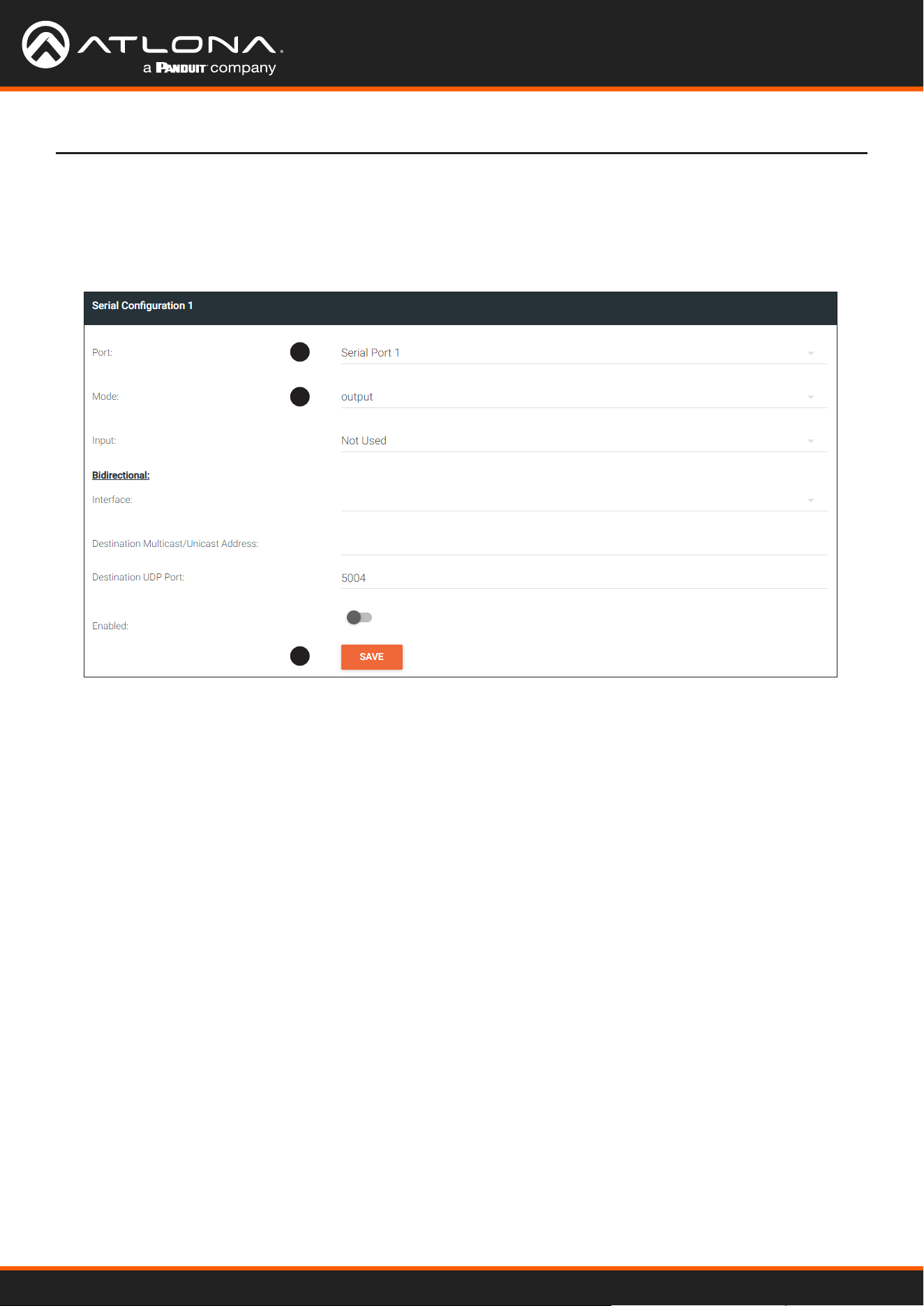
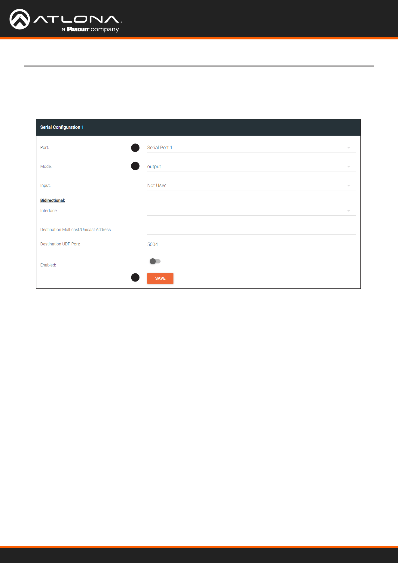
15. Under the Serial Conguration 1 window group, click the Port drop-down list and select the desired port.
16. Click the Mode drop-down list and select output.
17. Click SAVE.
Device Operation
15
16
17
Using OmniStream
™
with Velocity
™
Device Manager
36
Device Operation
Control using TCP Proxy
TCP/IP trac received by an encoder or decoder, on the dened IP:Port socket, are translated to RS-232, allowing
both control of source or display. Control is achieved using a control system, where all control commands are stored.
1. Login to the encoder or decoder and click the SERIAL menu. Under the Serial Port Conguration window
group, for the desired serial port, click the Mode drop-down list and select Serial.
2. Click the SAVE button.
1
3
4
5
6
7
2
3. Under the Serial Conguration 1 window group, click the Port drop-down list and select the desired serial port.
4. Click the Mode drop-down list and select tcpproxy.
5. Click the Interface drop-down list and select the desired Ethernet interface.
6. Enter the listening port in the Port eld.
7. Click the SAVE button.
Using OmniStream
™
with Velocity
™
Device Manager
37
Device Operation
Downstream Control using Triggering
TCP/IP trac received by an encoder or decoder, on the dened IP:Port socket, are translated to RS-232, allowing
both control of source or display. Control is achieved using a control system, where all control commands are stored.
1. Login to the decoder and click the SERIAL menu. Under the Serial Port 1 window group, click the Mode drop-
down list and select Serial.
2. Click the SAVE button.
3. Under the Serial Conguration 1 window group, click the Port drop-down list and select the desired serial port.
Option 1: Dening Commands on the Decoder
1
2
3
Using OmniStream
™
with Velocity
™
Device Manager
38
Device Operation
4
5
6
7
8
8
9
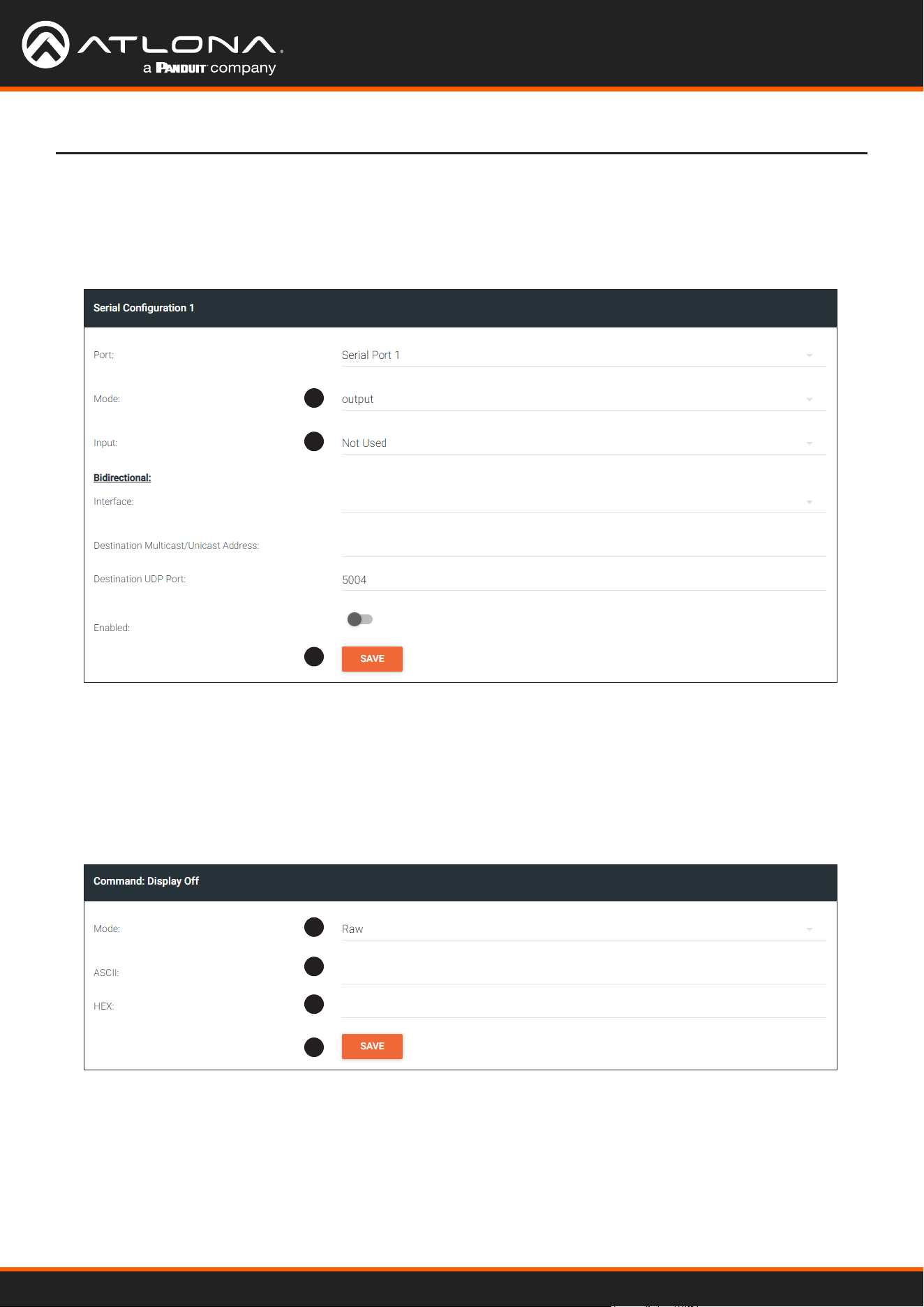
4. Click the Mode drop-down list and select output.
5. Click the Input drop-down list and select Not Used.
6. Click the SAVE button.
7. For each of the available commands, click the Mode drop-down list and select raw.
The available commands are: Display On, Display O, Volume Up, and Volume Down.
8. Enter the command data in either ASCII or hexadecimal format using the ASCII or HEX elds.
9. Click the SAVE button.
10. Open a Telnet/SSH session with the decoder and trigger display control using the following command:
TrigRS232X Y
where X is the number of the serial port: 1, 2
where Y is the command: on, o, vol+, or vol-.
Using OmniStream
™
with Velocity
™
Device Manager
39
Device Operation
Option 2: Dening Commands on the Encoder
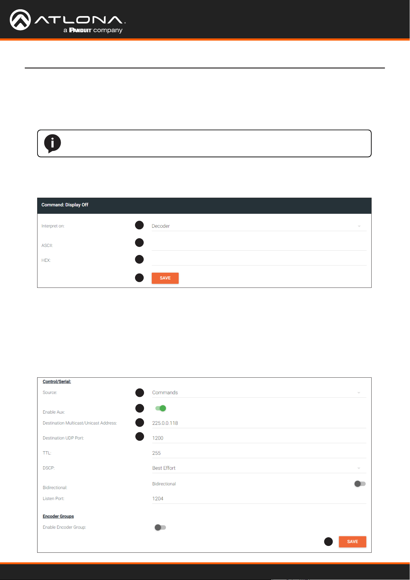
1. Login to the encoder and click the SERIAL menu. For each of the available commands, click the Interpret on
drop-down list and select decoder.
The available commands are: Display On, Display O, Volume Up, and Volume Down.
NOTE: Setting the Interpret on drop-down list to encoder implies that commands are dened/
stored on the encoder. If set to decoder, commands are dened/stored on the decoder.
2. Enter the command data in either ASCII or hexadecimal format using the ASCII or HEX elds.
3. Click the SAVE button.
1
2
2
3
4. Click the SESSION menu. Under the desired Stream, locate the Control/Serial section, click the Source drop-
down list, and select Commands.
5. Click the Enable Aux toggle switch to display the additional elds.
6. Enter the destination IP address and UDP port, of the decoder, in the Destination Multicast/Unicast Address
and Destination UDP Port elds, respectively. A multicast address can also be entered in the Destination
Multicast/Unicast IP Address eld.
7. Click the SAVE button.
4
5
6
6
7
Using OmniStream
™
with Velocity
™
Device Manager
40
8. Login to the decoder and click the IP INPUT menu. Locate an Input that does not contain a dened Multicast
address eld. In this example, Input 5 will be used. Note that if a multicast address was used in Step 6, then
that multicast address must be entered in the Multicast Address eld under Input 5.
9. Click the Enable toggle switch to enable the Input. When an Input is enabled, the toggle switch will be green.
10. Enter the UDP port, from Step 6, in the Port eld.
11. Click the SAVE button.
Device Operation
8
9
10
11
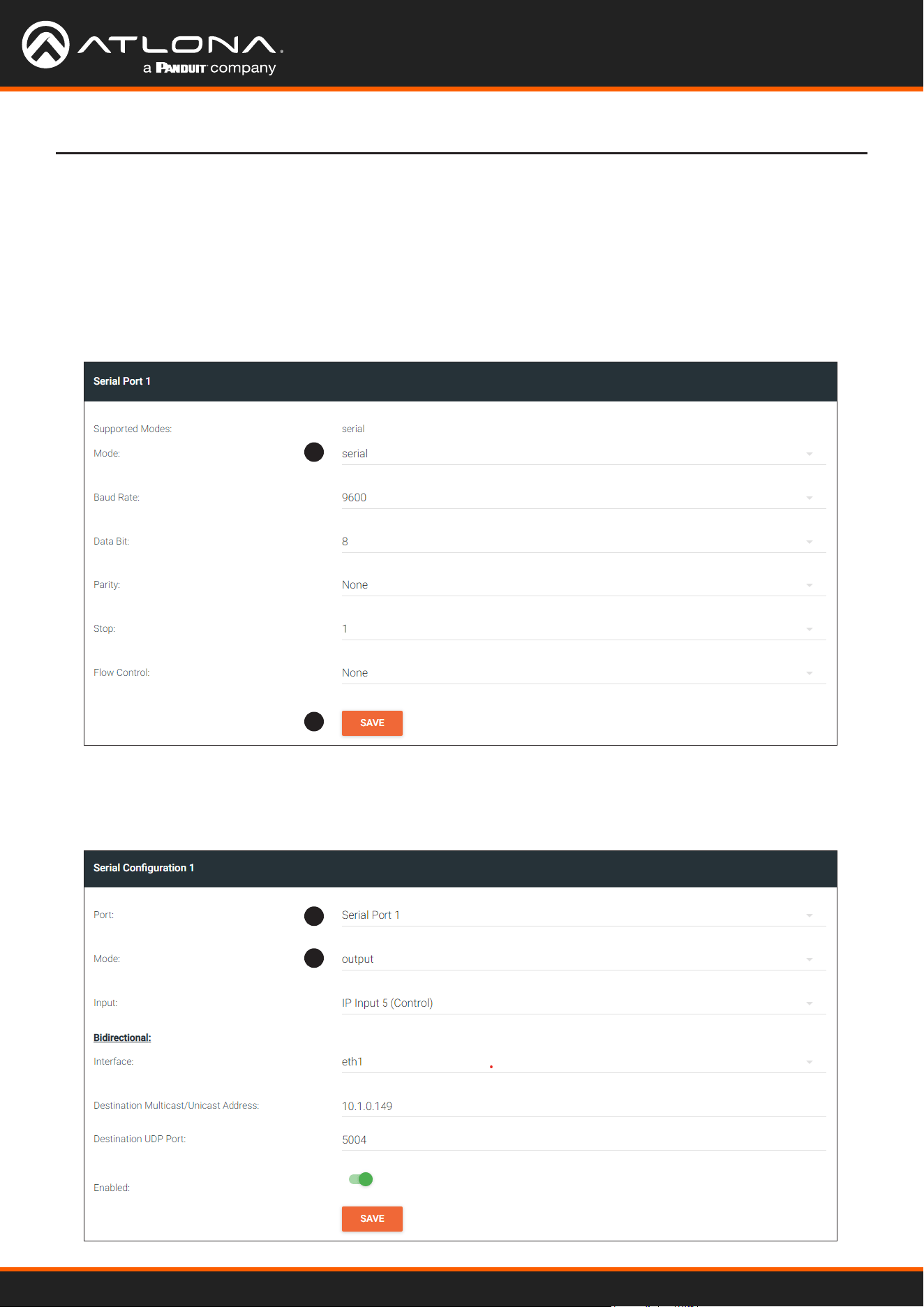
12. Click the SERIAL menu. Under Serial Port 1, set the Mode drop-down list to serial.
13. Click the SAVE button.
12
13
Using OmniStream
™
with Velocity
™
Device Manager
41
Device Operation
14. Under Serial Conguration 1, select the desired port.
15. Click the Mode drop-down list and select output.
16. Click the SAVE button.
14
15
16
17. Open a Telnet/SSH session with the encoder and trigger display control using any of the following commands:
InputBtn X
where X is the number of the input: 1, 2, or tog.
DisplayBtnX Y
where X is the number of the HDMI input: 1, 2.
where Y is the command: on, o, or toggle.
VolumeBtn X
where X is the volume-up or volume-down command.
Using OmniStream
™
with Velocity
™
Device Manager
42
The serial interface provides RS-232 control of both downstream and upstream devices. Source control is provided
by enabling bidirectional communication.
Upstream Control using RS-232
1. Login to the decoder and click the SERIAL menu. Under the Serial Port 1 window group, click the Mode drop-
down list and select Serial.
2. Click the SAVE button.
3. Under the Serial conguration window group, click the Port drop-down list and select the desired serial port.
4. Click the Mode drop-down list and select output.
Device Operation
1
3
4
2
Using OmniStream
™
with Velocity
™
Device Manager
43
Device Operation
5
6
7
7
8
9
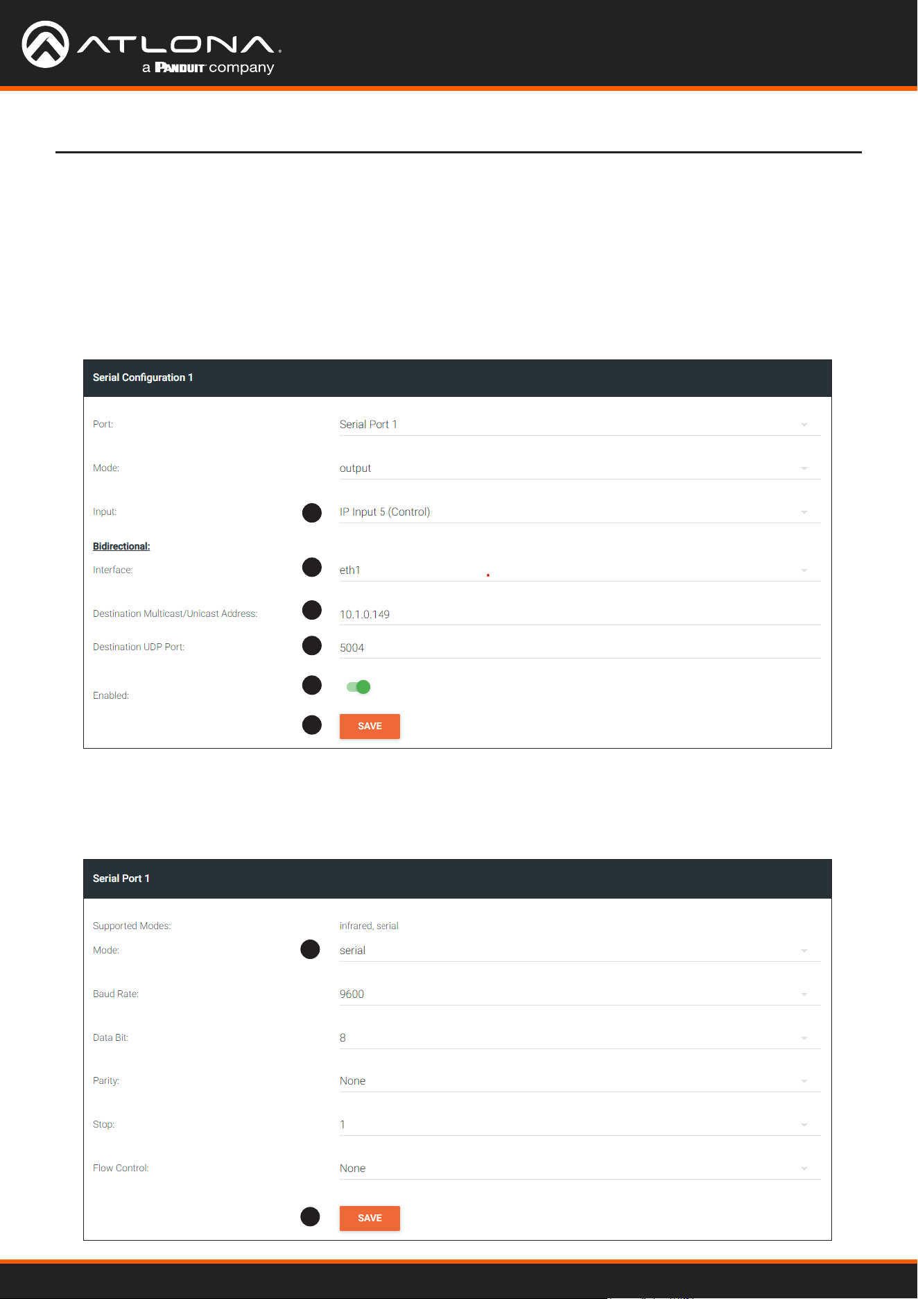
5. Click the Input drop-down list and select the input.
6. Under the Bidirectional section, click the Interface drop-down list and select the interface.
7. Enter the destination IP address (the IP address of the encoder) and UDP port in the Destination Multicast/
Unicast Address and Destination UDP Port eld, respectively.
8. Click the Enabled toggle switch to the enabled position. When enabled, the toggle switch will be green.
9. Click the SAVE button.
10. Login to the encoder and click the SERIAL menu. Under the Serial Port 1 window group, click the Mode drop-
down list and select Serial.
11. Click the SAVE button.
10
11
Using OmniStream
™
with Velocity
™
Device Manager
44
Device Operation
12. Under the Serial Conguration 1 window group, click the Port drop-down list and select Not Used.
13. Click the SAVE button.
12
13
14. Click the SESSION menu. Under the desired Stream, locate the Control/Serial section and click the Source
drop-down list to select the desired serial port.
15. Click the Enable Aux toggle switch to display the additional elds.
16. Enter the destination IP address and UDP port in the Destination Multicast/Unicast Address and Destination
UDP Port elds, respectively.
17. Click the Bidirectional toggle switch to enable it. When enabled, the toggle switch will be green.
18. Click the SAVE button.
14
15
16
16
17
18
Using OmniStream
™
with Velocity
™
Device Manager
45
1
2
Device Operation
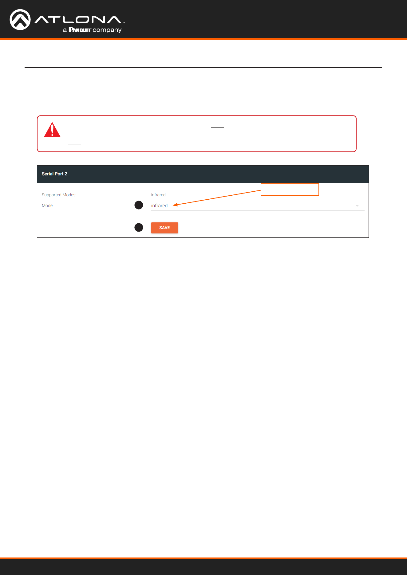
Upstream Control using IR
To control of headend source from downstream, refer to Upstream Control using RS-232 (page 42). Once
congured, make sure that the serial port is congured for infrared, as shown.
infrared
IMPORTANT: Depending on the hardware, IR may also be supported on RS-232 port 1.
Verify the OmniStream hardware version to determine its capabilities. For decoders, IR is
only suppored on RS-232 port 2.

Using OmniStream
™
with Velocity
™
Device Manager
46
Device Operation
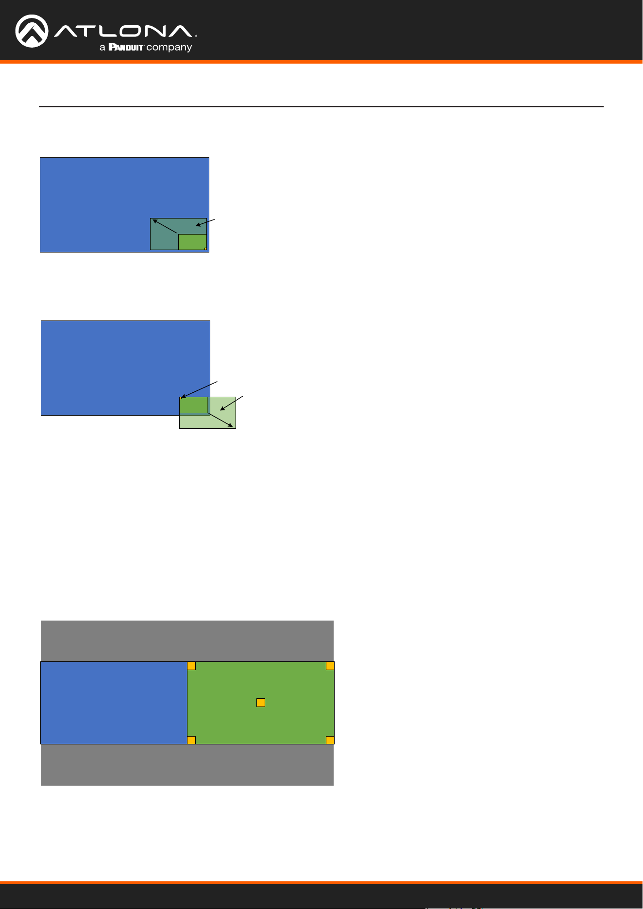
Multiview Nomenclature
A multiview is comprised of a canvas (display area) containing at least two, but no more than four subframes, where
each subframe has the following parameters:
In this rst example, the multiview is congured as a P-i-P view, where the P-i-P subframe has its anchor point
congured as bottom right. The incoming stream is 640 x 360.
By contrast, consider the same multiview layout, but with the P-i-P subframe having a top left anchor point.
Subframe 1
3840 x 2160
Subframe 2
640 x 360
Anchor Point
Subframe 1
3840 x 2160
Subframe 2
Expands to
1280 x 720
Subframe 1
3840 x 2160
Anchor Point
Subframe 2
640 x 360
Subframe 1
3840 x 2160
Subframe 2
Expands to 1280 x 720
(cropped)
Anchor Point
Subframe 1
3840 x 2160
Subframe 2
640 x 360
Anchor Point
Subframe 1
3840 x 2160
Subframe 2
Expands to
1280 x 720
Subframe 1
3840 x 2160
Anchor Point
Subframe 2
640 x 360
Subframe 1
3840 x 2160
Subframe 2
Expands to 1280 x 720
(cropped)
Anchor Point
General Overview
DEFINITIONS:
Subframe - The stream multicast IP address for the video.
Anchor point - A xed point on a subframe. The anchor point can be set to top-left, top-right,
bottom-left, bottom-right, or center. Each anchor point is dened by an x and y coordinate.
Z-order - Determines whether a frame appears in-front-of or behind another subframe.
Subframes with a larger z-order value will appear in front of a subframe with a smaller z-order
value.
NOTE: Multiview cannot be used in conjunction with fast switching and/or with video walls.
The images below shows the dierent anchor point options on a particular subframe. For any given subframe, only
one of these will be selected as the anchor point.
If the incoming stream changes resolution, the size of the subframe will change on the screen if scaling is not
congured on the encoder. While the decoder HDMI output can be scaled, there is no per-subframe scaling. This is
because the incoming stream is not scaled in the decoder. To illustrate this, consider the following examples.
Using OmniStream
™
with Velocity
™
Device Manager
47
Device Operation
Anchor Points
Anchor points will be placed on the canvas at the x and y coordinates of that canvas. If the decoder output is not
scaled, then this will correspond to the actual coordinates on the display. If the decoder output is scaled, then the
Anchor point will be rendered on the canvas at the specied coordinates, and then the entire output image will be
scaled.
Because of the way the VCx codec works, anchor points must be placed on coordinates where the x value is
divisible by 32 and the y value is divisible by 8. If a coordinate is entered that does not meet this requirement, then
the decoder will automatically snap the coordinates and notify the user of the change.
Top Left
Bottom Left
Bottom Right
Center
Top Right
In this case, when the stream changes to 1280 x 720, the subframe will grow in size and be cropped by the display,
because the top left anchor point has not change position
If the incoming stream changes resolution to 1280x720, then the subframe will grow in size, but it will still t on-
screen, because its bottom right Anchor point has not changed position.
Subframe 1
3840 x 2160
Subframe 2
640 x 360
Anchor Point
Subframe 1
3840 x 2160
Subframe 2
Expands to
1280 x 720
Subframe 1
3840 x 2160
Anchor Point
Subframe 2
640 x 360
Subframe 1
3840 x 2160
Subframe 2
Expands to 1280 x 720
(cropped)
Anchor Point
Subframe 1
3840 x 2160
Subframe 2
640 x 360
Anchor Point
Subframe 1
3840 x 2160
Subframe 2
Expands to
1280 x 720
Subframe 1
3840 x 2160
Anchor Point
Subframe 2
640 x 360
Subframe 1
3840 x 2160
Subframe 2
Expands to 1280 x 720
(cropped)
Anchor Point
Using OmniStream
™
with Velocity
™
Device Manager
48
Device Operation
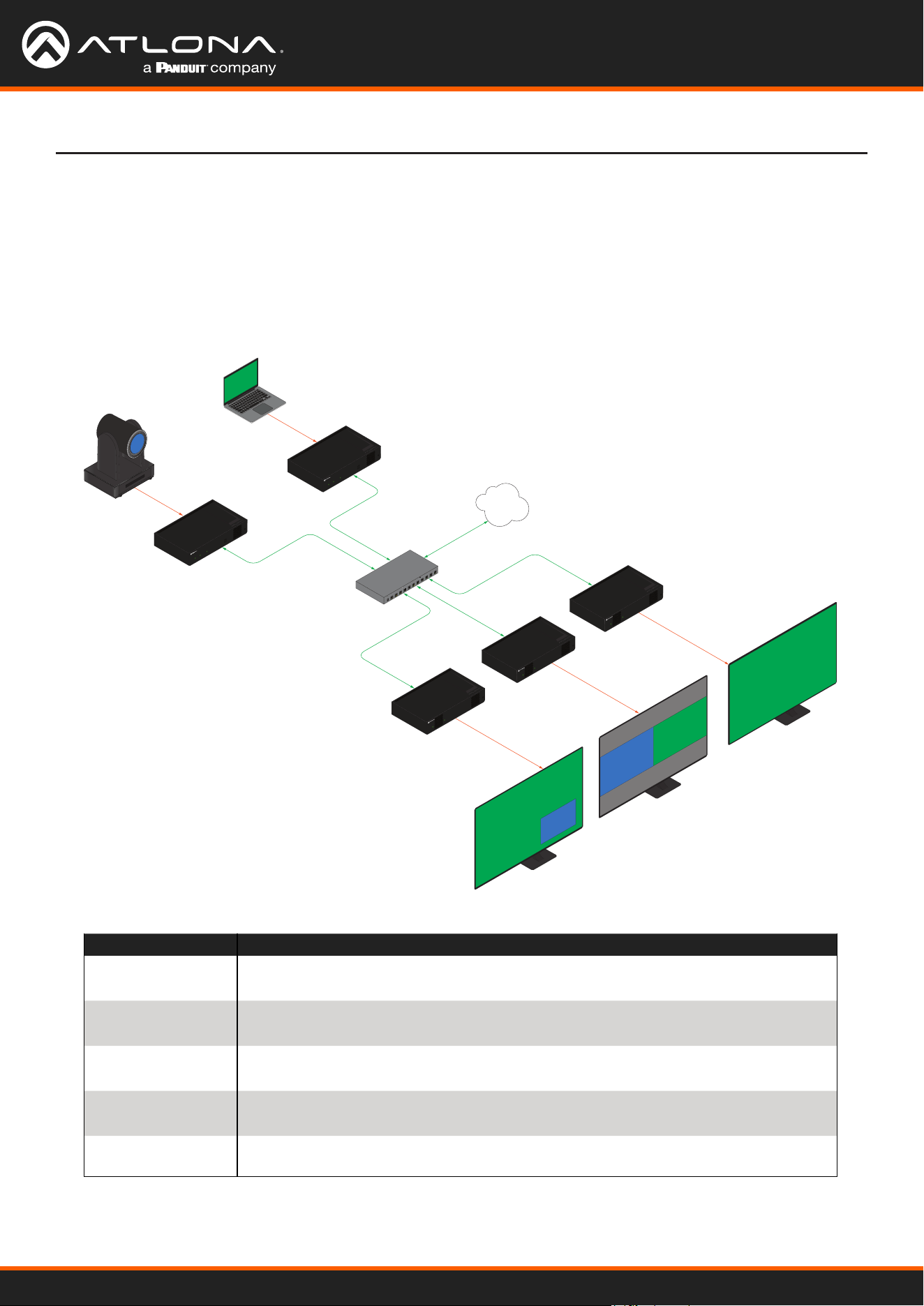
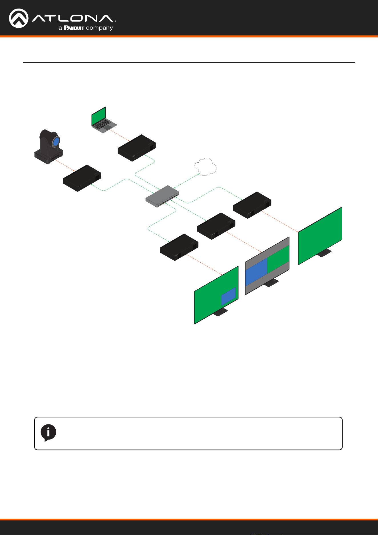
Multiview and Dual-Streaming Tutorial
This section provides a tutorial on conguring a multiview setup. In addition, the concept of dual-streaming will be
introduced. Review the diagram and the table below for a summary of how this setup will function. All encoders and
the decoders should be connected to the same local network.
Physical Connections
AT-OMNI-111
AT-OMNI-121
PoE Network Switch
Laptop
Ethernet
Ethernet
Ethernet
Ethernet
HDMI IN
HDMI OUT
HDMI OUT
HDMI OUT
LAN
HDMI
PWR
LINK
TM
O
MNI
S
TREAM
ID
TM
O
MNI
S
TREAM
LINKPWR
AT-OMNI-121
Display
Display
Display
Ethernet
TM
O
MNI
S
TREAM
LINKPWR
AT-OMNI-121
Ethernet
TM
O
MNI
S
TREAM
LINKPWR
AT-OMNI-111
HDMI IN
HDMI
PWR
LINK
TM
O
MNI
S
TREAM
ID
HD camera
4K
4K
720p
1080p 1080p
1
0
X
Z
o
o
m
F
1
.
6
-
F
3
.
0
f
4
.
7
m
m
-
f
4
7
m
m
1
0
X
Z
o
o
m
F
1
.
6
-
F
3
.
0
-
f
4
7
m
m
4K + 1080p
1080p + 720p
Encoder #1
Encoder #2
Decoder #1
Display #1
Display #2
Display #3
Decoder #3
Decoder #2
OmniStream Device Description
Encoder #1
(AT-OMNI-111)
• Dual-streaming conguration.
• Transmits both 1080p and 720p streams.
Encoder #2
(AT-OMNI-111)
• Dual-streaming conguration.
• Transmits both 4K and 1080p streams.
Decoder #1
(AT-OMNI-121)
• Multiview conguration (picture-in-picture).
• Subscribes to the 4K and 720p streams in multiview.
Decoder #2
(AT-OMNI-121)
• Multiview conguration (side-by-side).
• Subscribes to two 1080p streams in multiview.
Decoder #3
(AT-OMNI-121)
• Subscribes to a single 4K stream.
Using OmniStream
™
with Velocity
™
Device Manager
49
Device Operation
2. Click the INPUT menu.
3. Under the HDMI Input 1 window group, select Default HDR MCH from the EDID drop-down list.
4. Click the Supported Version drop-down list and select 2.2. Click the SAVE button, under the HDMI Input 1
window group, to commit changes.
5. Under the Encoder 1 window group, click the Input drop-down list and select HDMI Input 1.
6. Set the Max Bit Rate eld to 450.
7. Click the Scaler drop-down list and select 1920x1080.
8. Click the Thumbnail > Enable toggle switch to enable thumbnails of the source. This will verify that the input
source is congured correctly and will provide a visual reference for the encoder stream. Thumbnails are
updated every 2 seconds.
1. Click DEVICE INFO in the menu bar, then click the System Mode drop-down list and select VCx. Click the
SAVE button, in the lower-right corner of the screen, to commit changes.
Dual-Streaming Encoder Conguration
IMPORTANT: VCx must be enabled in order to use the Multiview feature.
NOTE: Thumnails can also be accessed at: http://<encoder-ip-address>/thumbnail/
thumbnail1.jpg. For dual-channel encoders, the secondary thumbail can be accessed at:
http://<encoder-ip-address>/thumbnail/thumbnail2.jpg.
9. Click the SAVE button, under the Encoder 1 window group, to commit changes.
10. Under the Encoder 2 window group, select HDMI Input 1 from the Input drop-down list.
11. Set the Max bit rate eld to 150.
12. Click the Scaler drop-down list and select 1280x720.
13. Click the SAVE button, under the Encoder 2 window group, to commit changes.
14. Click SESSION in the menu bar and congure each video stream using the information in the table bellow.
Audio streams will not be congured for this tutorial.
Encoder #1
Stream Interface Encoder Destination
Multicast/Unicast Address
Destination UDP Port
Stream 1
eth1 Encoder 1 226.0.0.1 1000
Stream 2
eth1 Encoder 2 226.0.0.2 1000
15. Click the SAVE button, under both Stream 1 and Stream 2 window groups, to commit changes.
This encoder is used with the HD camera and will be congured to dual-stream 1080p and 720p.

Using OmniStream
™
with Velocity
™
Device Manager
50
Device Operation
IMPORTANT: When conguring streams above 1920x1080p, Encoder 1 must be used.
8. Click the Thumbnail > Enable toggle switch to enable thumbnails of the source. This will verify that the input
source is congured correctly and will provide a visual reference for the encoder stream. Thumbnails are
updated every 2 seconds.
9. Click the SAVE button, under the Encoder 1 window group, to commit changes.
10. Under the Encoder 2 window group, select HDMI Input 1 from the Input drop-down list.
11. Set the Max Bit Rate eld to 150.
12. Click the Scaler drop-down list and select 1920x1080.
13. Click the SAVE button, under the Encoder 2 window group, to commit changes.
14. Click SESSION in the menu bar and congure each video stream using the information in the table bellow.
Audio streams will not be congured for this tutorial.
1. Click DEVICE INFO in the menu bar, then click the System Mode drop-down list and select VCx. Click the
SAVE button to commit changes.
2. Click the INPUT menu.
3. Under the HDMI Input 1 window group, select Default HDR MCH from the EDID drop-down list.
4. Click the Supported Version drop-down list and select 2.2. Click the SAVE button, under the HDMI Input 1
window group, to commit changes.
5. Under the Encoder 1 window group, click the Input drop-down list and select HDMI Input 1.
6. Set the Max bit rate eld to 750. This will cover resolutions up to 4K60 4:4:4.
7. Click the Scaler drop-down list and select 3840x2160.
Encoder #2
This encoder is used with a 4K source and will be congured to dual-stream 4K and 1080p.
Stream Interface Encoder Destination
Multicast/Unicast Address
Destination UDP Port
Stream 1
eth1 Encoder 1 226.0.0.3 1000
Stream 2
eth1 Encoder 2 226.0.0.4 1000
15. Click the SAVE button, under both Stream 1 and Stream 2 window groups, to commit changes.
Using OmniStream
™
with Velocity
™
Device Manager
51
IP Input 1 - 226.0.0.1:1000
IP Input 2 - 226.0.0.2:1000
IP Input 3 - 226.0.0.3:1000
IP Input 4 - 226.0.0.4:1000
1. Go the the decoder and click IP INPUT in the menu bar.
2. Congure the following elds, under each IP Input window group, as follows:
Decoder Conguration
IP Input Multicast Address Port
IP Input 1
226.0.0.1 1000
IP Input 2
226.0.0.2 1000
IP Input 3
226.0.0.3 1000
IP Input 4
226.0.0.4 1000
3. Click the Enabled toggle switch for each IP Input window group. When enabled, the toggle switch will be green.
4. Click SAVE, under each IP Input window group, to commit changes.
5. Click the HDMI OUTPUT menu.
6. Verify that each source can be displayed, independently. To do this, locate the Video section and click the Video
drop-down list. Alternate between the following selections to display each source.
If any of these sources are not displayed, return to the encoder IP INPUT, SESSION, and ENCODING menus to
verify that the conguration is correct.
Decoder #1, Decoder #2, and Decoder #3
Encoder #1 (source: HD camera)
Encoder #2 (source: Laptop)
Dual-streaming has been successfully congured on both encoders. This provides a total of four streams which are
listed in the tables, below, for reference.
The next step is to congure each decoder to subscribe to these streams. Although, in the tutorial diagram, each
decoder is subscribed to no more than two streams, we will congure all three decoders to access all four streams.
This will allow us to change the output on the displays, if desired.
Device Operation
Stream Encoder Resolution Stream Multicast IP Address Port
1 Encoder 1
1920x1080
Stream 1
226.0.0.1 1000
2 Encoder 2
1280x720
Stream 2
226.0.0.2 1000
Stream Encoder Resolution Stream Multicast IP Address Port
3 Encoder 1
3840x2160
Stream 1
226.0.0.3 1000
4 Encoder 2
1920x1080
Stream 2
226.0.0.4 1000
Using OmniStream
™
with Velocity
™
Device Manager
52
Multiview Conguration
1. Click MULTIVIEW in the menu bar.
2. Click the ADD NEW MULTIVIEW button.
3. The New Multiview dialog box will be displayed.
4. Enter a name for the multiview conguration in the Name eld. Since this decoder will be a picture-in-picture
layout, use the name multiviewpip.
The nal step is to congure the decoders to display the proper stream(s), as outlined in the tutorial diagram (shown
below).
AT-OMNI-111
AT-OMNI-121
PoE Network Switch
Laptop
Ethernet
Ethernet
Ethernet
Ethernet
HDMI IN
HDMI OUT
HDMI OUT
HDMI OUT
LAN
HDMI
PWR
LINK
TM
O
MNI
S
TREAM
ID
TM
O
MNI
S
TREAM
LINKPWR
AT-OMNI-121
Display
Display
Display
Ethernet
TM
O
MNI
S
TREAM
LINKPWR
AT-OMNI-121
Ethernet
TM
O
MNI
S
TREAM
LINKPWR
AT-OMNI-111
HDMI IN
HDMI
PWR
LINK
TM
O
MNI
S
TREAM
ID
HD camera
4K
4K
720p
1080p 1080p
1
0
X
Z
o
o
m
F
1
.
6
-
F
3
.
0
f
4
.
7
m
m
-
f
4
7
m
m
1
0
X
Z
o
o
m
F
1
.
6
-
F
3
.
0
-
f
4
7
m
m
4K + 1080p
1080p + 720p
Encoder #1
Encoder #2
Decoder #1
Display #1
Display #2
Display #3
Decoder #3
Decoder #2
Decoder #1
5. Click the Resolution drop-down list and select 3840x2160.
6. Click the Layout drop-down list to view the available layouts, and select pip-bottom-right.
7. Click the main (3840x2160) drop-down list and select IP Input 3 - 226.0.0.3:1000.
8. Click the bottom_right (1280x720) drop-down list and select IP Input 2 - 226.0.0.2:1000.
Device Operation
NOTE: Multiple multiview congurations can be created and saved. To display a dierent
multiview, go to the HDMI Output menu, locate the Video section and click the Input drop-
down list to select the desired multiview conguraiton.

Using OmniStream
™
with Velocity
™
Device Manager
53
Device Operation
9. Click the SAVE button.
10. Click HDMI OUTPUT in the menu bar.
11. Locate the Video section, click the Video drop-down list, and select multiviewpip. This is the name of the
multiview that was created in Step 4. The name multiview will always be used as a prex, indicating that the
selection is a multiview.
12. Click the SAVE button at the bottom of the HDMI Output 1 window group.
Decoder #2
Decoder #3
1. Click MULTIVIEW in the menu bar.
2. Click the ADD NEW MULTIVIEW button.
3. The New Multiview dialog box will be displayed.
4. Enter a name for the multiview conguration in the Name eld. Since this decoder will be a side-by-side layout,
use the name multiviewsbs.
5. Click the Resolution drop-down list and select 3840x2160.
6. Click the Layout drop-down list to view the available layouts, and select side-by-side.
7. Click the left (1920x1080) drop-down list and select IP Input 1 - 226.0.0.1:1000.
8. Click the right (1920x1080) drop-down list and select IP Input 4 - 226.0.0.4:1000.
9. Click the SAVE button.
10. Click HDMI OUTPUT in the menu bar.
11. Locate the Video section, click the Video drop-down list, and select the name of the side-by-side multiview
conguration that was created.
12. Click the SAVE button at the bottom of the HDMI Output 1 window group.
1. Since no multiview is used on this decoder, click HDMI OUTPUT in the menu bar.
2. Locate the Video section, click the Video drop-down list, and select IP Input 3 - 226.0.0.3:1000.
3. Click the SAVE button at the bottom of the HDMI Output 1 window group.
This completes the dual-streaming and multiview tutorial. Additional multiview features are documented in the
following pages.
Using OmniStream
™
with Velocity
™
Device Manager
54
Device Operation
Positioning Subframes
Each subframe in a multiview can be repositioned on the screen based on its anchor point. The anchor point (0,0)
represents the top left corner of the multivew canvas. For example, in the picture-in-picture example that was
created on Decoder #1, the settings for each subframe are as follows:
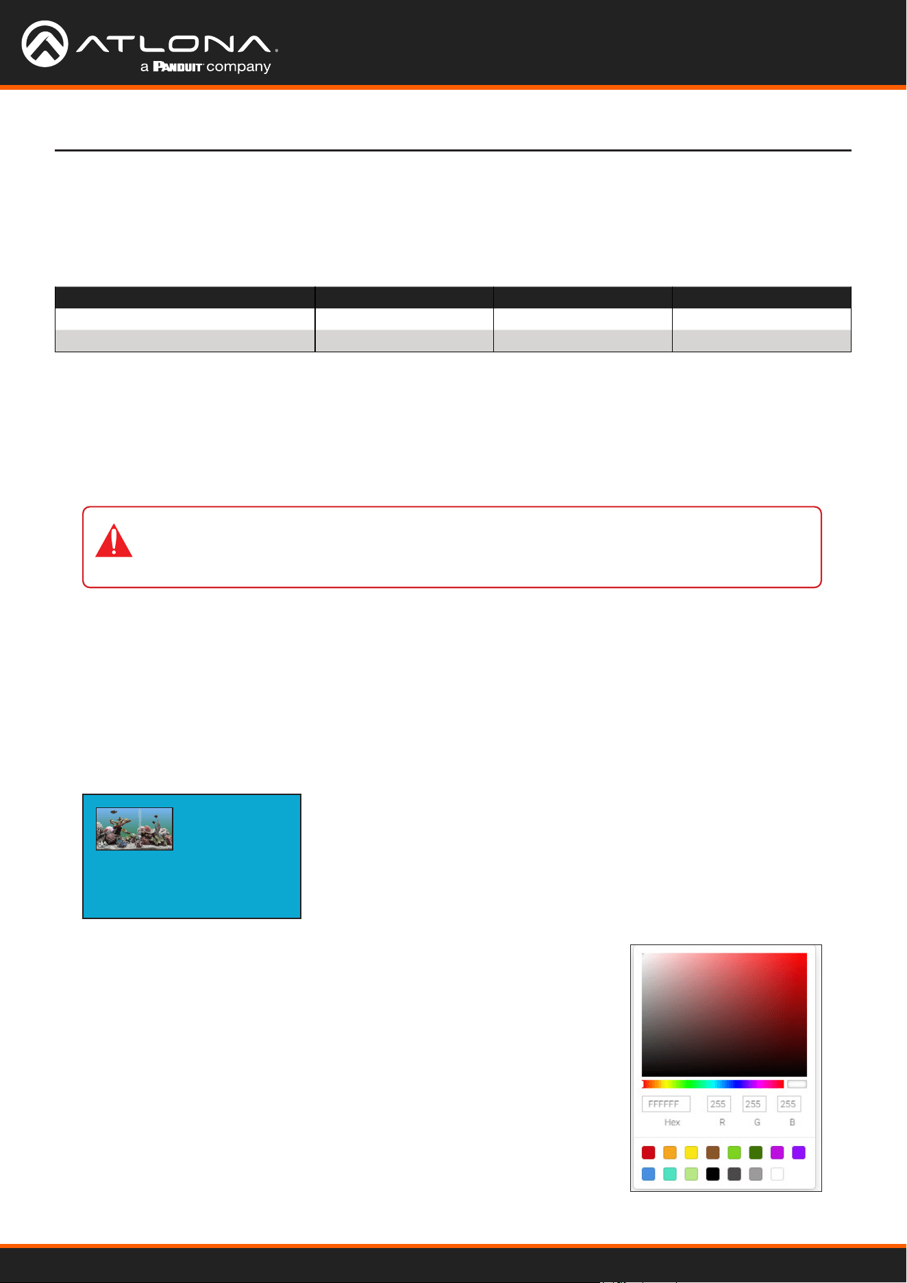
The background color can be seen if any portion of the canvas is not covered by a subframe. Refer to the illustration
below. For example, in this PiP conguration, subframe 1 contains no image. Instead of a blank background,
the background color is displayed. The default background color is black: (RGB) 0,0,0.
To move ip_input2 (camera source) to the left, decrease the x value.
1. Click the Multiview menu.
2. Locate the Subframe sections and adjust the x and y values as desired, based on the anchor point.
3. Click the SAVE button to commit changes.
Input Anchor x y
ip_input2 (226.0.0.2:1000)
bottom right
3808 2128
ip_input3 (226.0.0.3:1000)
top left
0 0
Changing the Background Color
1. Click the MULTIVIEW menu, then click the Available Multivew drop-down
list to select the desired multiview.
2. Click the Background Color swatch.
3. Click and drag the mouse across the palette to select the desired color.
Alternatively, values can be entered directly in the R, G, B, and Hex elds.
4. Click the SAVE button to commit changes.
IMPORTANT: X-values must be specied in increments of 32. Y-values must be specied
in increments of 8. If these increments are not used, then the decoder will automatically be
assigned the closest “correct” coordinate value and display a message of the change.
2
1
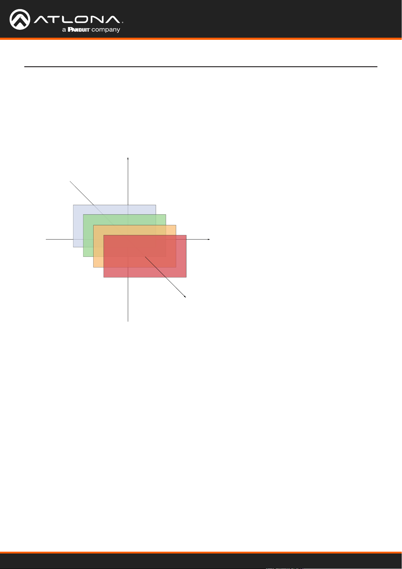
Using OmniStream
™
with Velocity
™
Device Manager
55
Device Operation
Changing the Z-Order
The ordering of overlapping subframes in two-dimensional space is referred to as the z-order. In the illustration
below, the red window is set to priority 4 and will be displayed on top of all other subframes. Assigning a subframe
to z-order 1 (the blue window) will move the subframe behind the other subframes. The larger the z-order value, the
higher the subframe priority will be. Subframes cannot share the same z-order value.
Note that subframes do not support transparency. This is only used in the diagram to illustrate how overlapping
subframes can be placed behind or in front or one another.
1. Click MULTIVIEW in the menu bar.
2. Click the Available Multiview drop-down list and select the desired multiview to be modied.
3. Click the name of the desired subframe to modify. Depending on the layout type, the name of each subframe will
vary (e.g. LEFT, RIGHT, BOTTOM_RIGHT, MAIN, etc).
4. Enter the z-order value in the Z-order eld.
5. Click the SAVE button to commit changes.
4
3
2
1
Z-Order = 1
Subframe on bottom
Z-Axis
X-Axis
Y-Axis
Z-Order = 4
Subframe on top

Using OmniStream
™
with Velocity
™
Device Manager
56
Device Operation
Adding Subframes
Deleting a Subframe
Deleting a Multiview
Multiview supports a maximum of 4 subframes. As long as the maximum number of subframes is not exceeded,
additional subframes can be added. This provides for customization of existing layouts.
1. Click the MULTIVIEW menu.
2. Click the Available Multiview drop-down list to select the multiview to be changed.
3. Click the ADD SUBFRAME button.
4. The New Subframe dialog will be displayed.
5. Enter the title of the new subframe in the Name eld.
6. Click the Input drop-down list to select the desired input. Only a list of currently congured IP inputs will be
available from this list. If a new IP input is desired, it will need to be congured.
7. Enter the desired values in the X and Y elds, relative to the anchor point.
8. Click the Anchor drop-down list and select the desired anchor point.
9. Enter the z-order value in the z-order eld.
10. Click the SAVE button to commit changes.
1. Click the MULTIVIEW menu.
2. Click the Available Multiview drop-down list to select the multiview to be changed.
3. Under the name of the subframe (LEFT, RIGHT, TOP_LEFT, etc.), click the DELETE button. The subframe will
be immediately removed from the multiview.
1. Click the MULTIVIEW menu.
2. Click the Available Multiview drop-down list to select the multiview to be deleted.
3. Under the CONTAINER submenu, click the DELETE button.
IMPORTANT: In order to delete a Multiview, the Multiview to be deleted must not be in use by
the decoder. Click the HDMI OUTPUT menu, then click the Video > Input drop-down list to
select another IP input or a dierent Multiview.
Using Audio in Multiview
When using multiview, a decoder can only subscribe to a single audio stream. To use an audio stream in multiview,
simply congure the audio as part of the session (Audio > Source > hdmi_input1, for example). Refer to Creating
a Session (page 20) for more information.

Using OmniStream
™
with Velocity
™
Device Manager
57
Device Operation
Conguring Audio Output
In addition to passing audio directly from the encoder to the decoder, both the AT-OMNI-121 and AT-OMNI-122
provide two additional audio options
• HDMI audio can be de-embedded and output to two-channel analog audio.
• Two-channel analog audio can be embedded and output over HDMI.
This section covers both methods. If using a single-channel decoder, only a single AUDIO IN and AUDIO OUT port
will be available.
De-embedding audio will extract the HDMI audio and automatically downmix to two-channel analog audio, using the
included captive-screw connectors.
De-embedding Audio
1. Connect the power supply to the DC 48V connector on the decoder.
2. Connect the included 5-pin captive screw connectors to the AUDIO OUT ports. Refer to the OmniStream User
Manual for wiring information.
3. Login to the decoder and click HDMI Output in the menu.
4. Scroll down to the Audio section and click the Analog Power toggle switch to enable it. When enabled, the
toggle switch will be orange. The Analog Power Status indicator, above the toggle switch, will be green. This
indicates that the external power supply is connected to the decoder.
Audio from the source will now be heard on the ANALOG OUT port of the decoder. Note that when audio is de-
embedded, it will not longer be audible using the HDMI OUT ports on the decoder.
Embedding audio will replace the existing HDMI audio source, normally heard on the output of the decoder.
The analog audio will be heard on the HDMI OUT port of the decoder.
Embedding Audio
1. Connect the power supply to the DC 48V connector on the decoder.
2. Connect the audio source to the AUDIO IN ports, using the included 5-pin captive screw connectors. Refer to
the OmniStream User Manual for wiring information.
3. Go to the decoder.
4. Click HDMI Output in the menu bar.
5. Scroll down to the Audio section and click the Analog Power toggle switch to enable it. When enabled, the
toggle switch will be orange. The Analog Power Status indicator, above the toggle switch, will be green. This
indicates that the external power supply is connected to the decoder.
Audio from the source will now be heard on the HDMI OUT ports on the decoder.
IMPORTANT: When using analog audio inputs on the OmniStream decoder, the decoder must
be powered using the 48V power supply (AT-PS-48083-C). This power supply is sold separately
and can be purchased from Atlona.

Using OmniStream
™
with Velocity
™
Device Manager
58
Device Operation
1. Click Control > Sites in the menu bar to expand the list of buildings and rooms.
2. Click the desired room from the Site list.
Creating Video Walls
NOTE: It is assumed that the selected room has already been populated with enough displays
to construct a video wall, along with required number of OmniStream encoders and decoders.
Refer to the Velocity User Manual for more information on adding displays and OmniStream
units to a room.
3. The Modify Room screen will be displayed. Click the Edit Room Technology icon.
4. Click the Add Technology icon.
5. Click the Miscellaneous > Atlona > Velocity Video Wall: VELOCITY-VIDEO-WALL. The video wall technology
will be added to the room.
6. Click the Edit Room Device icon in the video wall technology window.
7. The Video Wall / Pixel Space Dimensions dialog will be displayed. This dialog will automatically be displayed
when the video wall driver is edited for the rst time. The name of the video wall can be modied in the Alias
eld, if desired. Close this dialog.
The following section assumes familiarity with site and room management within Velocity. Refer to the Velocity User
Manual for more information on these topics.
The default video wall dimensions are set to 3840 x 2160. To modify the video wall size, follow Steps 7a through
7e. To continue with the default video wall dimensions, click the CLOSE button and go to step 8.
a. Click the Lock Pixel Space toggle switch to disable it. When disabled, the toggle switch will turn gray.
b. Under Pixel Space Dimensions, click the drop-down list to select the desired video wall dimensions.
c. To create a custom size for the video wall, enter the desired dimensions under the Custom section.
Enter the width and height directly, or use the spinner controls at the far end of each eld, to adjust the
values.
d. Save the video wall dimensions by clicking the Lock Pixel Space toggle switch to enable it.
e. Click the CLOSE button to dismiss the dialog.

Using OmniStream
™
with Velocity
™
Device Manager
59
Device Operation
Before continuing, refer to the Pixel Space tool bar at the top of the screen. The following identies each icon:
a b c d e f g h i j k l
a. Displays
Click to icon to show the Displays window on the
left side of the screen. In this mode, displays can
be edited.
b. Presets
Click this icon to display the Presets window on
the left side of the screen. In this mode, presets
can be edited, added, or deleted.
c. Drop Zones
Click this icon to display the Drop Zones window
on the left side of the screen. Refer to Creating
and Using Drop Zones (page 65) for more
information.
d. Auto Arrange
Click this icon to auto-arrange the number of
displays in the Pixel Space window into the
selected number of rows and columns.
e. Lock
When locked, this icon will turn red, and prevent
accidental repositioning of displays or changing
presets. To unlock the displays (for adjustment
purposes), click this icon again.
f. Delete All
Click this icon to delete all displays within the
Pixel Space window. This icon will only be
available if displays are present in the Pixel
Space window. This icon is only enabled if
displays have been added to the Pixel Space
window.
g. Pixel Space
Click this icon to display the VideoWall dialog
box, allowing modication of both the Video Wall
and Pixel Space settings.
h. Zoom
Click this icon to display the zoom y-out slider
control. Click and drag the slider to adjust the
zoom factor of the Pixel Space window.
i. Apply Preset
Click this icon to apply the current preset. Click
the down arrow next to this icon to display the
Apply Preset y-out menu. This control denes
when Velocity automatically applies a preset: 1)
Auto apply preset on save; 2) Auto apply preset
on source change.
j. Save
Click this icon to save the current layout/settings.
Click the down-arrow, next to this icon, to display
the Save y-out menu option, allows enabling or
disabling of auto-saving.
k. Undo
Click this icon to undo the last operation.
l. Redo
Click this icon to redo the last operation.
Clicking this icon after an undo operation will
restore the previous setting.
8. Under the Displays window, on the left side of the screen, drag and drop the desired displays to the to Pixel
Space window.
Alternatively, to add all displays to the Pixel Space windows without manually using drag-and-drop, click ADD
REMAINING, at the bottom of the Displays window. This will automatically populate the Pixel Space window
with all available displays. Note that if all displays have been dragged to the Pixel Space window, then this
option will be grayed out.
9. Click the Auto Arrange icon in menu bar at the top of the Pixel Space window. Move the mouse within the
Auto Arrange pop-up dialog to adjust the size of the video wall. Click the lower right-most blue square of the
video wall to commit the selection.

Using OmniStream
™
with Velocity
™
Device Manager
60
Device Operation
Landscape Orientation
If any displays have been mounted upside-down, the orientation can be corrected, without having to remount the
displays in the correct orientation.
a. Click the Edit icon (pencil icon) in the upper-right corner of the display that requires adjustment.
b. The dialog for the selected decoder will be displayed.
c. Click the Rotation drop-down list and select the desired rotation. If the image on the display is upside-down,
select 180 degrees.
d. Click the CLOSE button to commit changes.
If any displays have been mounted upside-down, the orientation can be corrected, without having to remount the
displays in the correct orientation.
a. Click the Edit icon (pencil icon) in the upper-right corner of the display that requires adjustment.
b. The dialog for the selected decoder will be displayed.
c. Click the Rotation drop-down list and select the desired rotation. If the image needs to be rotated from
landscape to portrait, select 90 degrees. If the display is mounted upside-down AND requires rotation
from landscape to portrait, select 270 degrees.
d. Click the CLOSE button to commit changes.
Portrait Orientation
IMPORTANT: Portrait Mode is only supported on single-channel decoders.
Once Auto Arrange has been applied, the Pixel Space window will appear. It should be noted that each display
can be rearranged if necessary. To reposition displays, click and drag them to the appropriate places, within
the Pixel Space window. Note that each display is identied with a name and an IP address, in the upper-left
corner. Refer to the Velocity User Manual for more information on naming devices.
10. Click the Lock Displays icon in the menu bar of the Pixel Space window. This is optional. However, enabling
this feature will prevent accidental repositioning of the displays, during the conguration procedure. When
locked, this icon will turn red. Both the Trash and Auto Arrange icons will be disabled. To unlock the displays
(for adjustment purposes), click the Lock Displays icon again.
11. Click the Save icon in the upper-right corner of the Pixel Space window. This will save the current layout.

Using OmniStream
™
with Velocity
™
Device Manager
61
Presets are used to save window layouts, within the Pixel Space window. Once a preset is created it can be recalled
at any time.
1. Click the Presets icon. When clicked, this icon will turn green and the Presets window will be displayed on the
left side of the screen.
2. Click Add, under Presets.
3. Enter than name of the preset in the Preset Edit dialog, then click CLOSE to save the preset name and dismiss
the dialog.
4. Under the Sources window, on the left side of the screen, drag and drop the desired source(s) to each display in
the Pixel Space window. Note that the same source can be mapped to other displays.
Sources can also be re-sized “on the y” to achieve the desired presentation. To re-size a source, click and drag
the source window horizontally, vertically, or diagonally. Release the mouse to commit the changes. Refer to the
Velocity User Manual for more information on manipulating source windows.
Creating Presets
Device Operation
NOTE: When source windows are resized, they will “snap” to the nearest vertical or horizontal
border, depending upon the direction that the mouse cursor is being moved. Source windows
cannot occupy fractions of a display window.
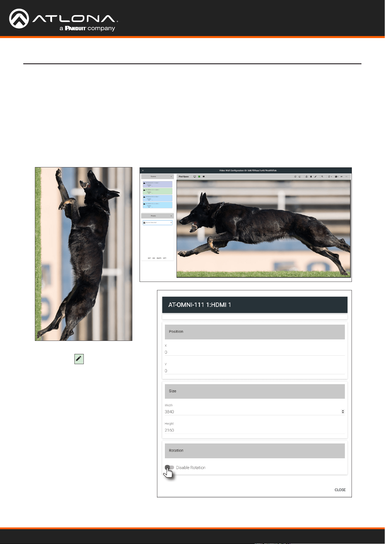
Using OmniStream
™
with Velocity
™
Device Manager
62
Preset Orientation
There may be some situations in which content that is spread across multiple displays must be rotated.
Two examples are shown below.
In the following example, a single source is spread across three vertical displays. The source content (shown on the
left) is rotated -90 degrees. In order for the content to be displayed correctly, the source must be rotated.
Figure 1.1 - Source content Figure 1.2 - Source content properly rotated to span three vertically rotated
displays.
Example 1: Content requiring rotation.
1. Click the icon in the upper-right
corner of the screen. The source
dialog will be displayed.
2. Locate the Disable Rotation toggle
switch at the bottom of the dialog.
3. Verify that the toggle switch is set
to the far-left position. The toggle
switch will be gray when rotation is
enabled.
4. Click CLOSE to commit changes and
dismiss the dialog box.
Device Operation
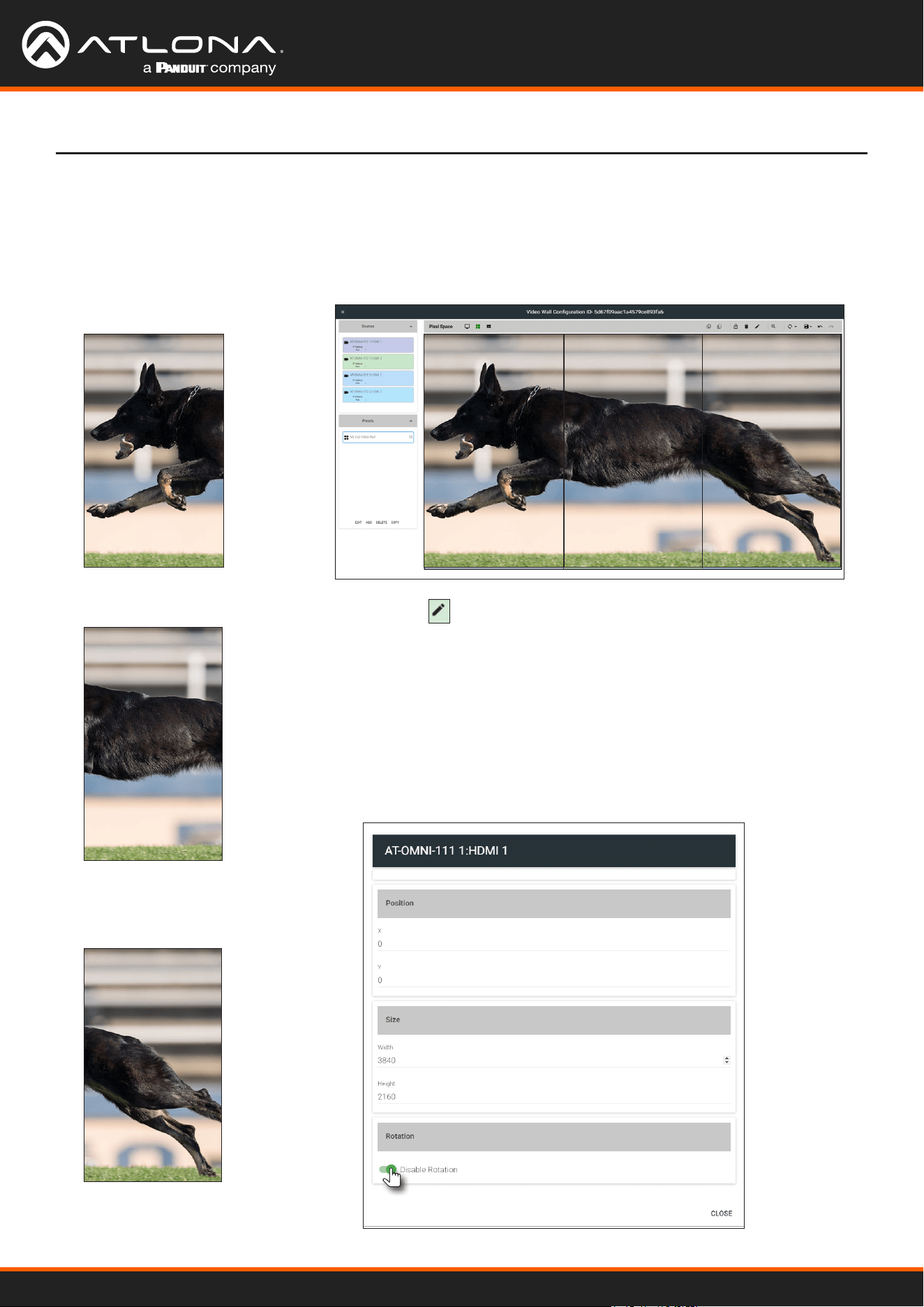
Using OmniStream
™
with Velocity
™
Device Manager
63
In this example, three sources are spread across three vertical displays. The content (shown on the left) was created
to be displayed horizontally. In this case, rotating the source is not required.
Figure 1.1 - Source content
Source 1
Source 2
Source 3
Figure 1.2 - Source content properly rotated to span three vertically rotated
displays.
Example 2: Content that does not require rotation.
1. Click the icon in the upper-right corner of the source window.
The source dialog will be displayed.
2. Locate the Disable Rotation toggle switch at the bottom of the
dialog.
3. Verify that the toggle switch is set to the far-left position. The toggle
switch will be green when rotation is disabled.
4. Click CLOSE to commit changes and dismiss the dialog box.
5. Repeat steps 1 through 4 for each source.
Device Operation
Source 1 Source 2 Source 3
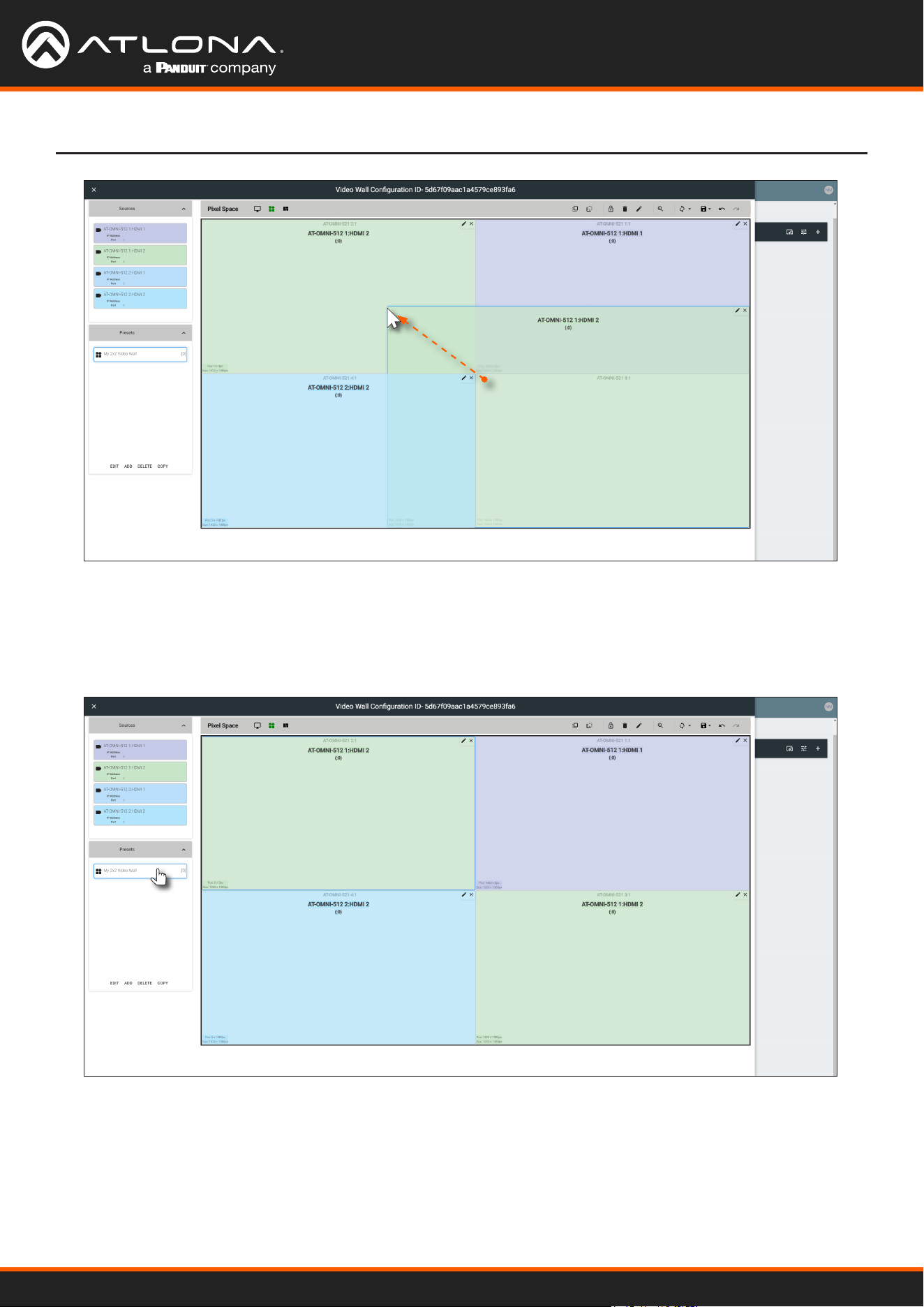
Using OmniStream
™
with Velocity
™
Device Manager
64
Device Operation
5. Repeat steps 2 through 4 to create additional presets. Once the desired presets have been created, click the
preset name to recall it. The video wall will be updated with the selected preset.
Refer to the Atlona Velocity User Manual for more information on using and recalling presets.
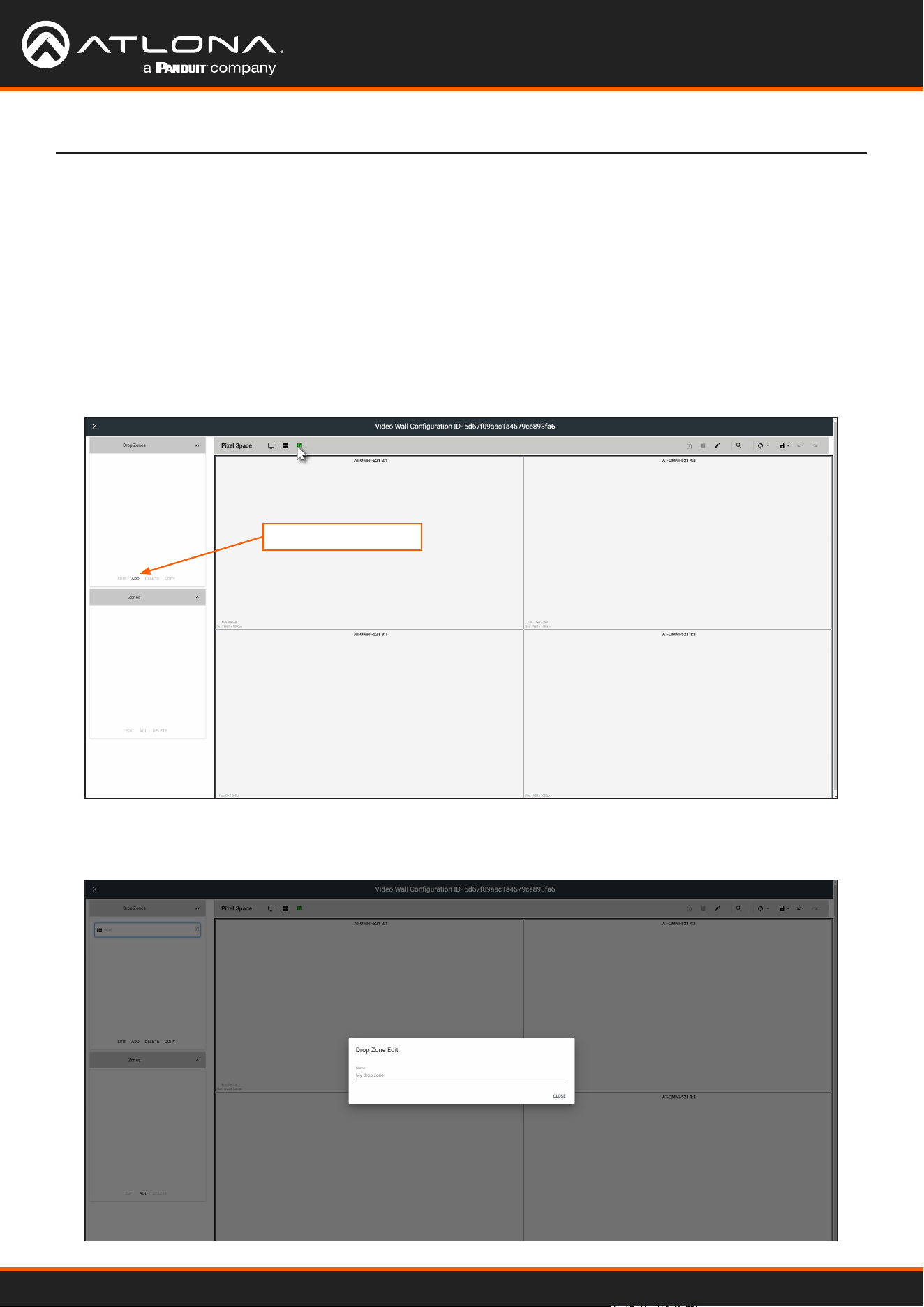
Using OmniStream
™
with Velocity
™
Device Manager
65
Device Operation
Creating and Using Drop Zones
Drop Zones are “containers”, allowing sources to be placed (“dropped”) in real-time on a video wall. Drop Zones are
similar to presets except that, unlike presets, Drop Zone content can be changed on-the-y within the Video Wall
Control Screen.
1. Populate the Pixel Space window with the desired devices.
2. Click the Lock Displays icon to lock the devices in place.
3. Click the Drop Zones icon in the Pixel Space menu bar.
4. Click ADD, under the Drop Zones window, on the left side of the screen. This will create the Drop Zone preset.
5. Click EDIT and provide a name for the Drop Zone in the Drop Zone Edit dialog box.
6. Click the CLOSE button to commit the change.
ADD
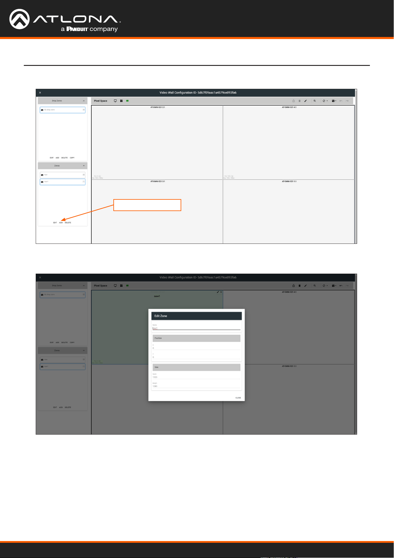
Using OmniStream
™
with Velocity
™
Device Manager
66
Device Operation
7. Click ADD, under the Zones window.
8. Click EDIT and provide a name for the Zone, in the Edit Zone dialog box. Click Close to save the change.
Note that each time the ADD button is clicked, a new Drop Zone container is created. In this rst example, two
Drop Zone containers are created. When adding containers, note that the position of each container is created in
the same position, within the Pixel Space window.
ADD
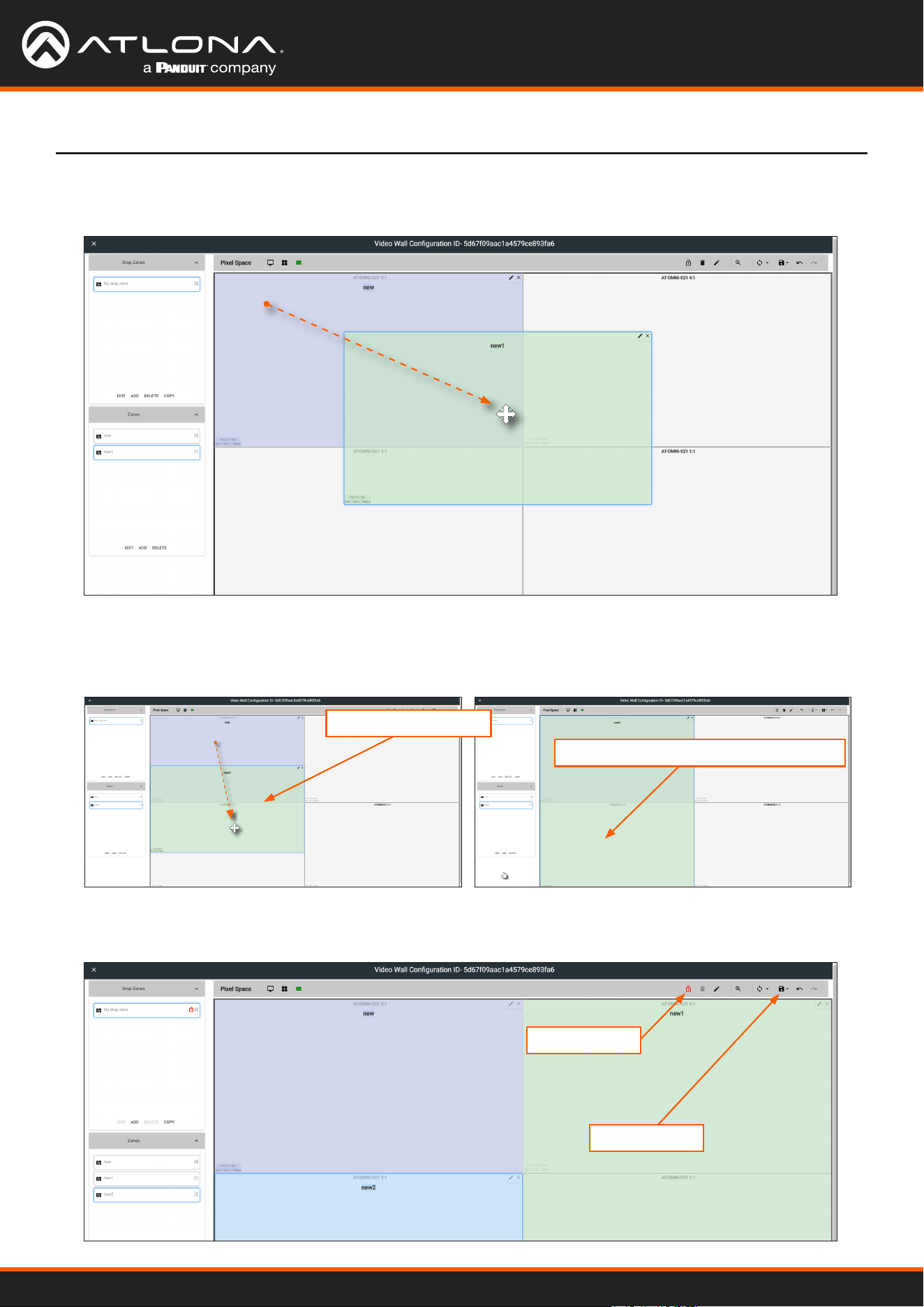
Using OmniStream
™
with Velocity
™
Device Manager
67
Device Operation
9. Drag each container to the desired area on the video wall. To place a container on each device, left-click and
drag, then release when a majority of the window is placed over the device.
If a container is positioned over the intersection of two windows, then it will automatically be resized to
accommodate both devices, as shown below. If placed over the corner intersection of more than two windows,
then the container will be resized to cover all devices occupying that space.
10. Click the Lock Preset button, one the containers have been placed in the desired positions.
Container automatically resized
Window Intersection
Lock Preset
Save
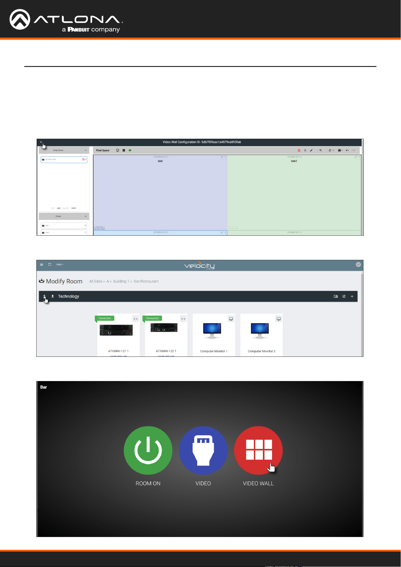
Using OmniStream
™
with Velocity
™
Device Manager
68
Device Operation
11. Repeat the above steps to create additional Drop Zone presets. Each Drop Zone preset can have a dierent
number of containers. However, the number of containers that are created should not exceed the number of
devices within the Pixel Space window.
12. Click the Save icon to commit all changes.
13. Close the Video Wall Conguration window, by clicking the X, in the upper-left corner of the screen.
14. Click the Launch Control icon, in the far-left corner of the Modify Room screen.
15. Click the VIDEO WALL icon.
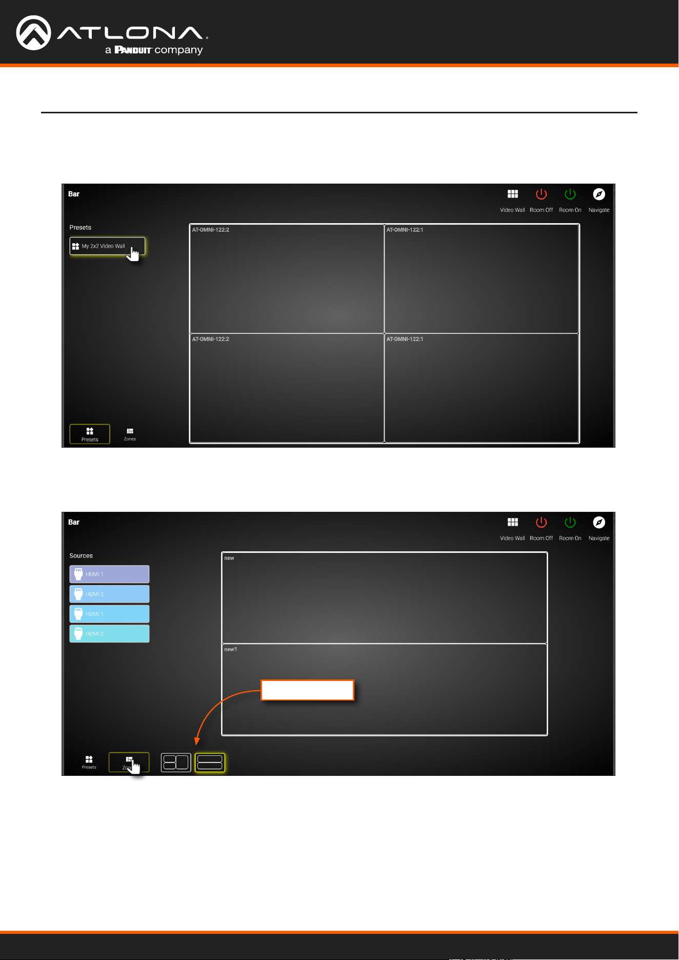
Using OmniStream
™
with Velocity
™
Device Manager
69
Device Operation
16. The Presets portion of the control screen will be displayed. All presets that were created, will be listed on the
left-hand side of the screen, as shown below. Note in this example, only one preset was created. Click the
desired preset to recall it.
17. Click Zones, in the lower-left corner of the screen to access the Drop Zones, which were created earlier. In the
example example below, two Drop Zones were created.
Created Zones
The rst Drop Zone that was created, shows two containers on the left, and a single container on the right.
The second Drop Zone, only uses two containers: one on the top and one on the bottom. The Preset which we
created is a 2x2 video wall and represents the physical layout of the displays. Drop Zones are containers and act
as a “map” to where the video sources will be applied. Refer to the next page for an example.
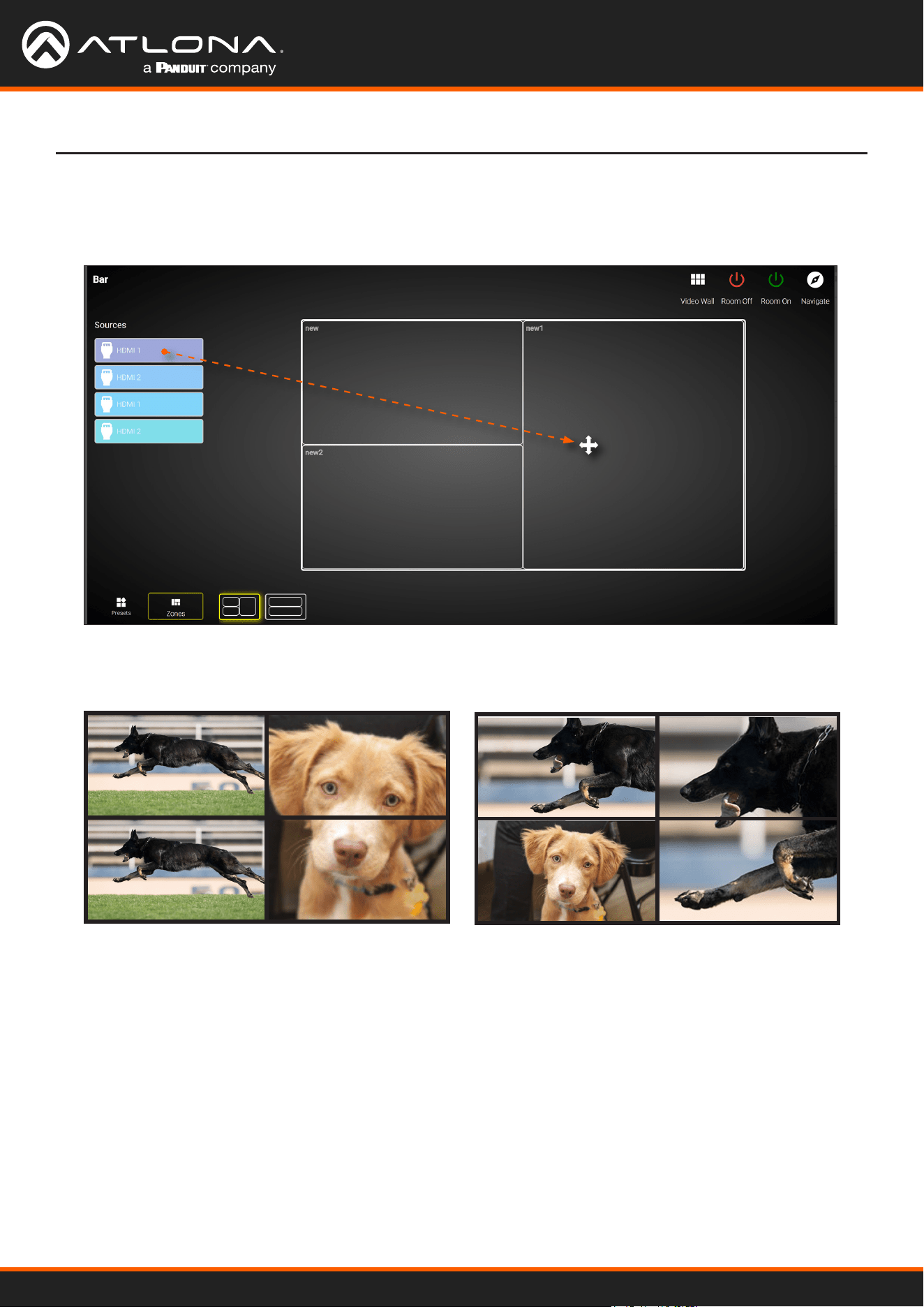
Using OmniStream
™
with Velocity
™
Device Manager
70
Device Operation
The rst Drop Zone will can dynamically apply sources to the preset, which is a 2x2 video wall, to the top-left,
bottom-left, and both or only one display(s) on the right-hand side. Some possible combinations are shown
below. Drop Zone containers have been labeled alphabetically, for reference.
Note that although the top-right and bottom-right displays are physically separate, dragging and dropping a
source from the left-hand side of the screen to Drop Zone container “C”, will “map” the source to both displays.
To change to a dierent source, drag and drop a source from the left-hand side of the screen to the source to be
replaced.
A
B
C C
C
A A
B B
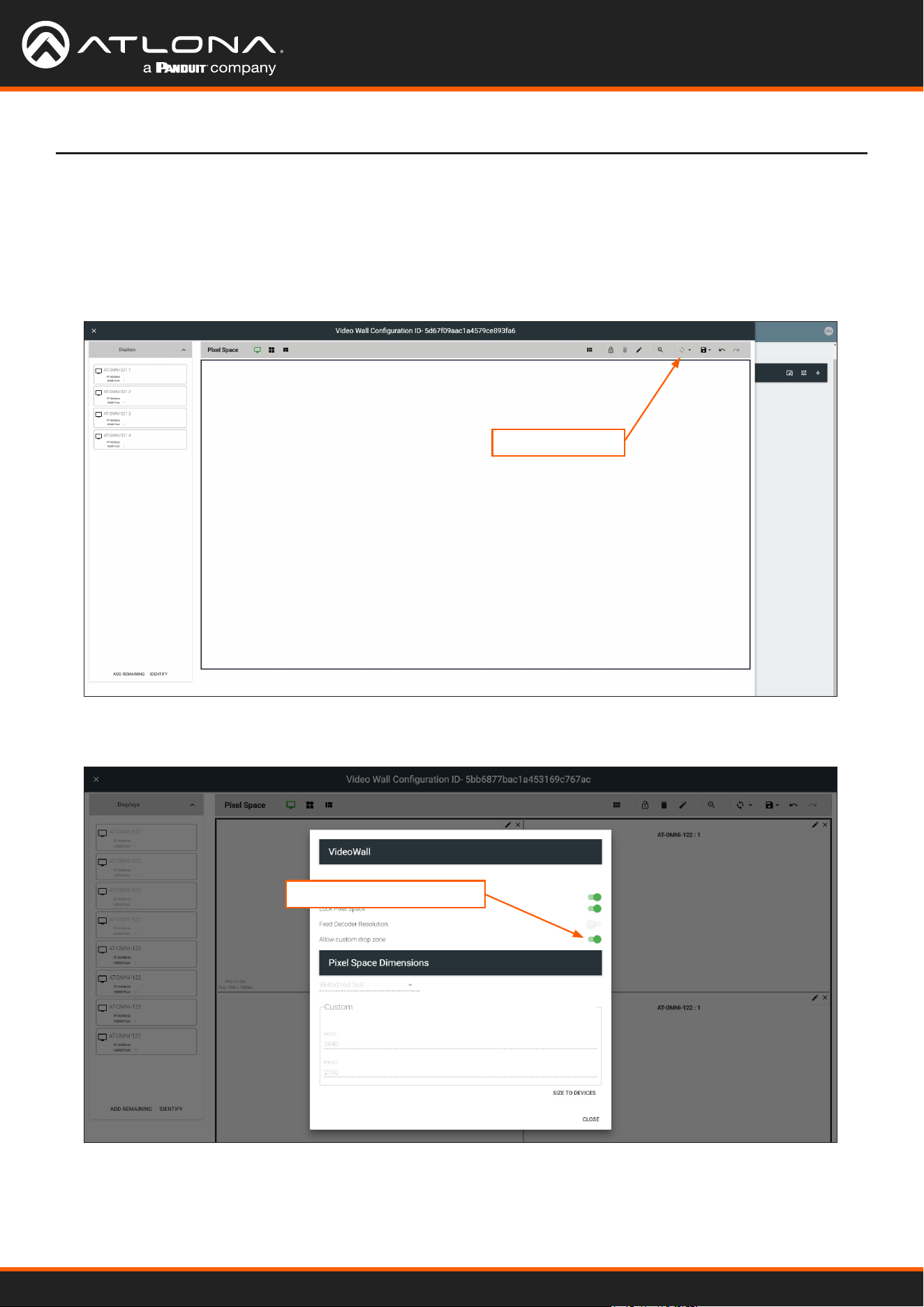
Using OmniStream
™
with Velocity
™
Device Manager
71
Device Operation
In addition to creating user-dened Drop Zones, the Velocity Video Wall also includes a Custom Drop Zone.
This unique type of Drop Zone allows dynamic re-sizing of sources to be mapped across any of the decoders.
1. Return to the Video Wall Conguration screen and click the Pixel Space icon, in the Pixel Space menu bar.
2. Click the Allow custom drop zone toggle switch to enable it. When enabled, this toggle switch will be green.
3. Click CLOSE to save changes and dismiss the dialog box.
4. Click the Save icon in the top-right portion of the Video Wall Conguration screen to commit changes.
Custom Drop Zones
Pixel Space icon
Allow custom drop zone
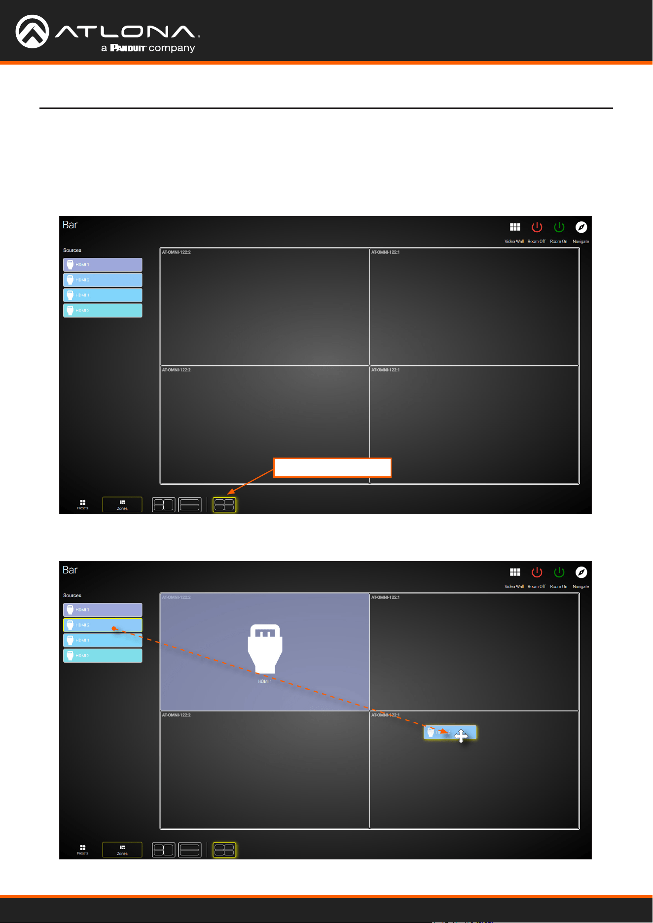
Using OmniStream
™
with Velocity
™
Device Manager
72
Device Operation
5. Close the Video Wall Conguration screen and then click the Launch Control icon on the Modify Room
screen.
6. Click the VIDEO WALL icon to enter video wall control screen.
7. Click Zones at the bottom of the screen, then click the Custom Drop Zone icon.
8. Drag-and-drop sources from the left side of the screen, as performed with normal Drop Zones.
Custom Drop Zone
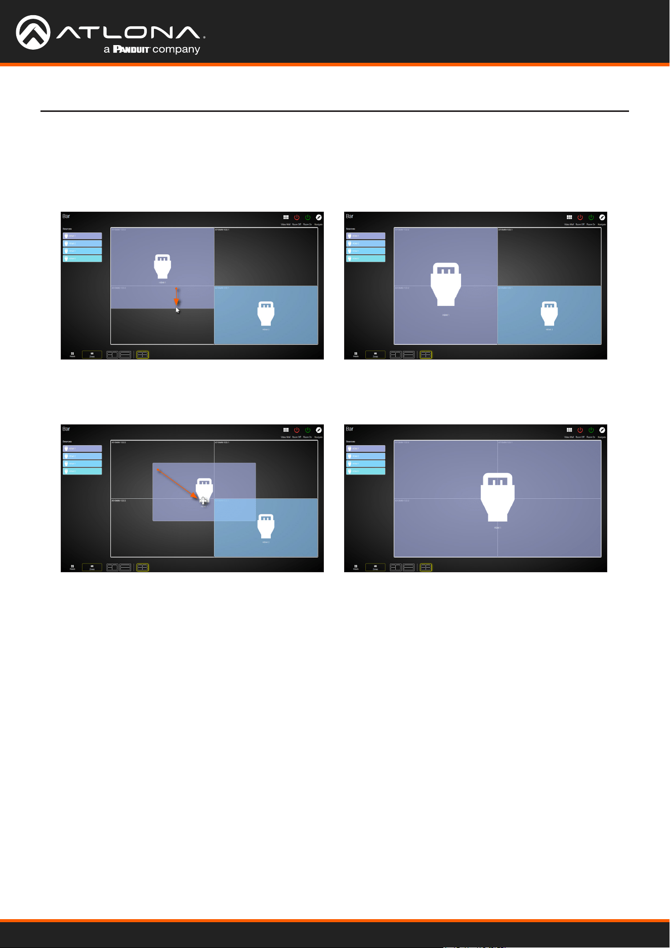
Using OmniStream
™
with Velocity
™
Device Manager
73
Device Operation
9. Resize or reposition windows by clicking and dragging the edges of each source, horizontally / vertically, to the
desired area of a container.
To reposition the source to a dierent container(s), click in the middle of a source, then drag and drop to the
desired container(s).
If the source is dropped at the intersection of two containers, the source will automatically be resized to ll both
containers. In the example below, the source will be displayed on all four screens.

Using OmniStream
™
with Velocity
™
Device Manager
74
OmniStream decoders have the ability to identify missing streams, should an input be disconnected from the
encoder, and will recover the image almost instantaneously. The decoder can access the same stream from two
separate multicast addresses and switch between them, when necessary.
1. Go to the decoder.
2. Click HDMI OUTPUT in the menu bar.
3. Under the Video section, click the Backup Mode drop-down list to select the desired mode.
1. Go to the decoder.
2. Click HDMI OUTPUT in the menu bar.
3. Under the Video section, locate the Conguration Grace Period eld and enter the desired value, in seconds.
By default, this value is set to 0 (zero).
4. Click the SAVE button, at the bottom of the HDMI Output window group.
Conguring Redundant Streams
* Switching time will be dependent upon the network switch that is used, as well as the number of hops between
encoders and decoders on the network.
Mode Description
Off
Redundancy off; output will never switch to the backup stream.
Join Active
The decoder sends a join request only when the primary stream is lost or if the decoder
is manually switched to the backup stream. Switch time will not exceed 5 seconds.*
Join Always
The decoder joins both the Primary and Backup stream at the same time. Switch time
will not exceed 0.5 seconds.
During use, the decoder can be switched to another multicast stream. However, if the decoder encounters a missing
stream, during the switch and when redundancy is enabled, then this will cause the decoder to automatically failover
to the multicast source congured as the backup. To prevent the decoder from automatically making the redundancy
switch, when redundancy is enabled, a grace period can be entered. By default, the grace period is set to 0
seconds. If set to 0 seconds, automatic failover will occur if the stream is interrupted, for any reason.
Redundancy Grace Period
Device Operation
4. Click the SAVE button, at the bottom of the HDMI Output window group.
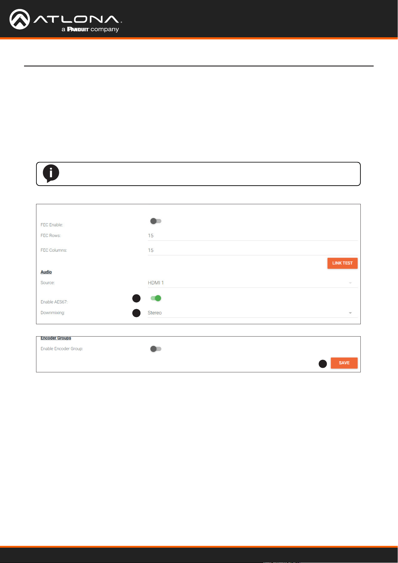
Using OmniStream
™
with Velocity
™
Device Manager
75
AES67 Audio
AES67 audio is a standard for high-performance audio streaming over IP, providing several features such as
synchronization, media clock identication, and connection management. AES67 does not support bitstream/
compressed audio formats, such as Dolby® Digital, and others. Source audio must be transmitted as LPCM up to
eight channels at 192 kHz / 24-bit.
Device Operation
1. Go to the encoder, click SESSION in the menu bar, then locate the Audio section under the desired stream.
Click the Enable AES67 toggle switch to enable this feature. When enabled, the toggle switch will be green.
2. Select the type of downmixing from the Downmixing drop-down list, if desired. Available options are: None,
Mono, and Stereo.
3. Click the SAVE button within the Stream window group.
4. Go to the decoder interface and click OTHER in the menu bar.
5. Click SAP in the left menu bar.
6. Click the Enable toggle switch to enable SAP. When enabled, the toggle switch will be green. If the decoder,
Dante controller, or DSP is to receive AES67 audio, this step is required.
7. Click the SAVE button in the SAP window group.
NOTE: If the Enable AES67 toggle switch is enabled, the SAP will also be enabled.
1
2
3
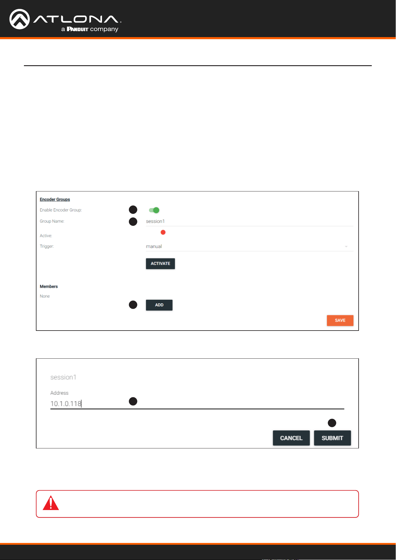
Using OmniStream
™
with Velocity
™
Device Manager
76
1. Go to the encoder, click SESSION in the menu bar, and locate the Encoder Groups section. Click the Enable
Encoder Groups toggle switch. When enabled, the toggle switch will be green.
2. Locate Encoder Groups and enter a name for the group in the Group Name eld. The default group names for
Stream 1 and Stream 2 are session1 and session2, respectively.
3. Under Members, click the ADD button.
Device Operation
Encoder Grouping
Grouping encoders allows a group of encoders to feed a single decoder, simultaneously. The stream will be
displayed by the decoder using either manual or automatic input-selection, based on the presence of a source
signal.
1
2
3
4
5
IMPORTANT: The IP address for each encoder must be added to the group. This includes the
IP address of the encoder that is being used to create the group.
4. Enter the IP address of the encoder to be added to the group.
5. Click the SUBMIT button.
6. Repeat steps 3 through 5 for each encoder to be added to the encoder group.
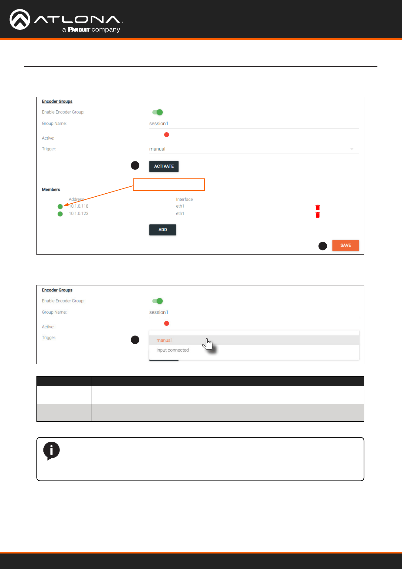
Using OmniStream
™
with Velocity
™
Device Manager
77
Device Operation
7. Click the Activate button to enable encoder grouping. When enabled, the Active indicator(s) will be green.
Mode Description
manual Use this setting to manually enable the input. When set to manual, click the Activate
button to perform the input switching.
input connected Use this setting to allow the encoder group to use automatic input detection. Once a
new source is connected, that source becomes the active source.
8. Click the Trigger drop-down list and select the desired trigger mode.
NOTE: Setting Trigger to input connected should not be used when Slate Mode is set to
Auto. Doing so will cause the slate to be displayed when switching inputs. If encoder auto-
switching is being used, set the Slate Mode to Auto, on the decoder. Refer to Slate / Logo
Insertion (page 83) for more information.
7
8
9
Active indicators
9. Click the SAVE button, at the bottom of the Stream window group to commit changes.
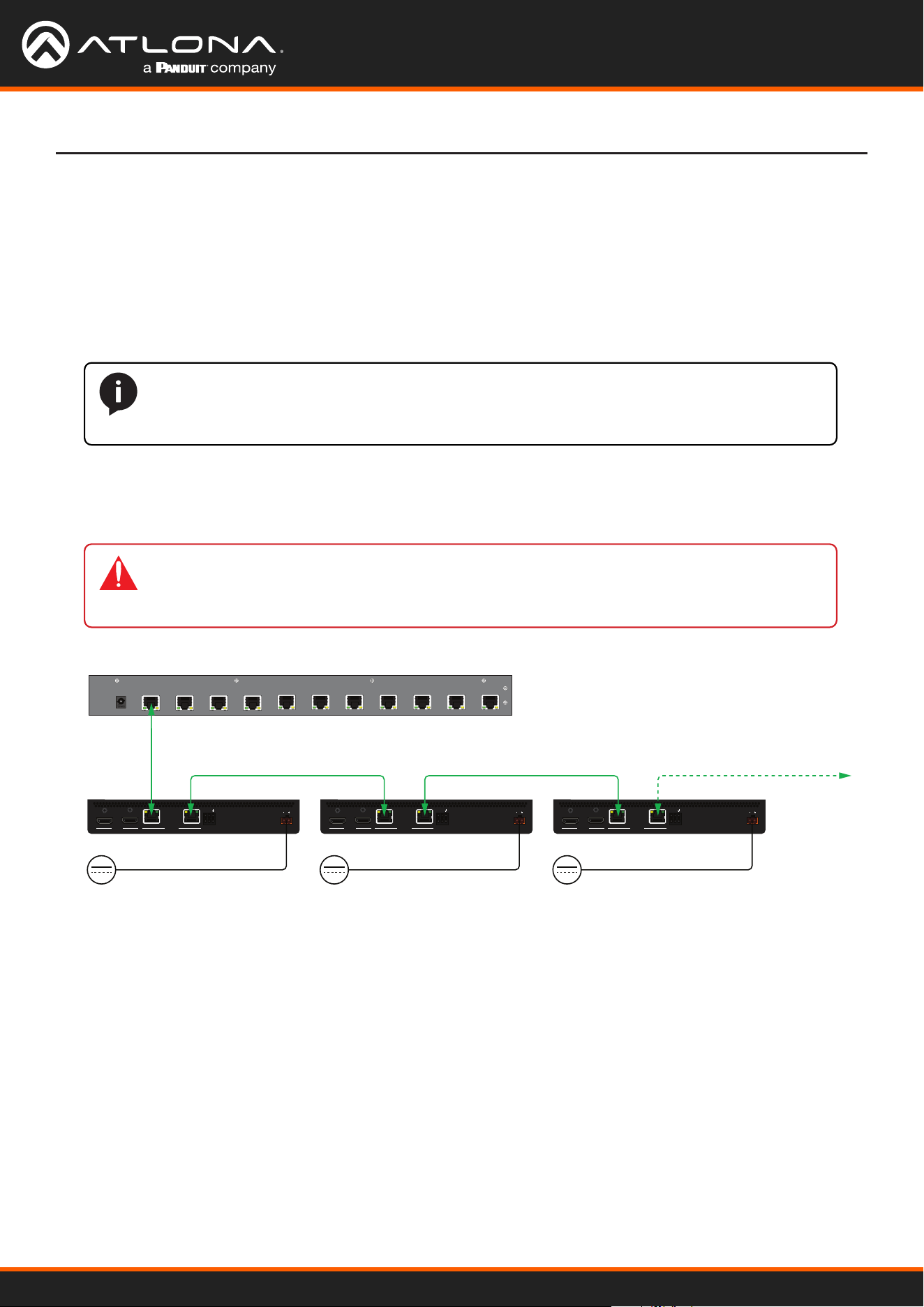
Using OmniStream
™
with Velocity
™
Device Manager
78
Device Operation
Daisy-Chaining Encoders
Encoders can be daisy-chained to one another. This is particularly useful when only a single distribution point and
one display exists in a room. Daisy-chaining transforms multiple encoders into a single multiple-input encoder with a
single multicast IP address.
In the diagram below, three dual-channel OmniStream encoders are connected to a switch. In order to daisy-chain
them, they must be reconnected in a dierent conguration. Each encoder has been labeled with an arbitrary IP
address, for identication purposes.
AT-OMNI-112
ETHERNET
RS-232
DC 48V
RX
TX
1
2
HDMI IN
2
1
21
PoE (optional) Network Switch
AT-OMNI-112
ETHERNET
RS-232
DC 48V
RX
TX
1
2
HDMI IN
2
1
21
192.168.11.190
Ethernet Ethernet EthernetEthernet
192.168.11.191 192.168.11.193
AT-OMNI-112
ETHERNET
RS-232
DC 48V
RX
TX
1
2
HDMI IN
2
1
21
+48V / 0.83 A DC+48V / 0.83 A DC+48V / 0.83 A DC
1. Reconnect the encoders to one another, and to the switch, as shown in the illustration below.
2. Connect the optional OmniStream power supply (AT-PS-48083-C) to each encoder in the chain.
3. Login to the encoder.
4. Click SESSION in the menu bar.
5. Create an encoder group for using each encoder in the chain. Refer to Encoder Grouping (page 76) for more
information. Since there are three encoders in this example, each encoder will be listed under the SESSION
page, as shown. Encoders can be added to an encoder group in any order.
To delete an encoder from the Members list, click the icon to the right of its IP address.
NOTE: Single-channel encoders do not support daisy-chaining. In addition, the OmniStream
R-Type Encoder (AT-OMNI-512) does not support daisy-chaining and cannot be combined with
OmniStream Pro daisy-chain congurations.
IMPORTANT: The optional OmniStream power supply (AT-PS-48083-C) must be connected to
each encoder that is daisy-chained, in order to supply the required power. Note that since each
encoder must use an external power supply, connection to a PoE switch is not required.
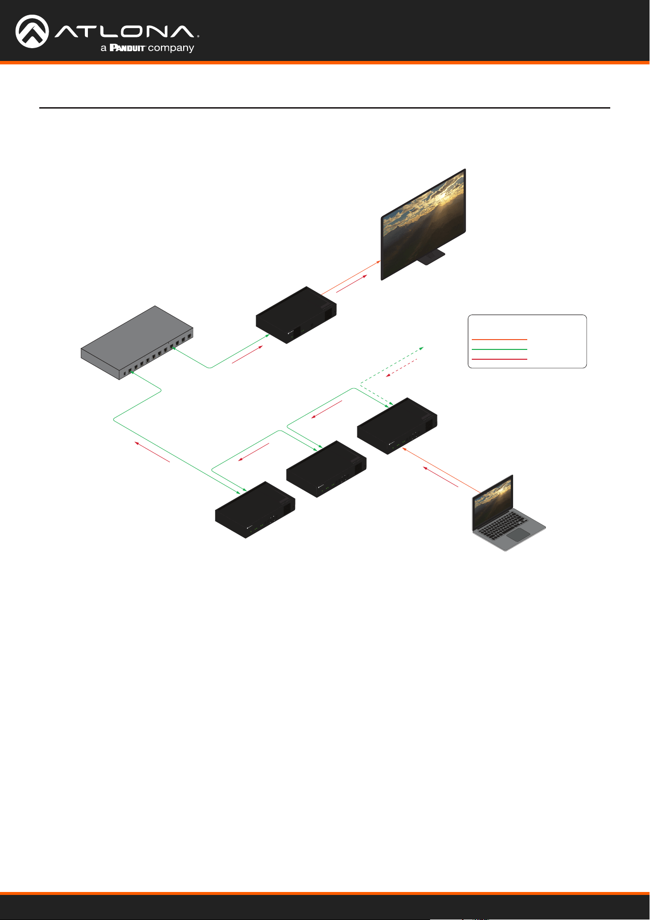
Using OmniStream
™
with Velocity
™
Device Manager
79
Device Operation
6. Click the Trigger drop-down list to select the trigger mode. Selecting the trigger mode will set how the
OmniStream encoder will respond when a source is disconnected/connected.
The diagram above shows a basic daisy-chain setup. The path of the A/V signal is identied with red arrows.
When encoders are daisy-chained, they function as one single encoder. In this example, daisy-chaining three dual-
channel encoders, creates a single “logical” encoder with six HDMI inputs.
When daisy-chaining encoders, the following rules apply:
• All encoders will stream content using the same multicast IP address. Therefore, the decoder must be
subscribed to this multicast IP address in order to display the content.
• Daisy-chained encoders can only display one source at a time. Click the Trigger drop-down list to determine
how the encoder will handle switching between sources.
• The last source that is connected will be the one that is displayed. However, this is only occurs if the Trigger
mode is set to input connected.
• Pressing the INPUT button, on the front panel of an encoder, will toggle between HDMI inputs.
Laptop
Display
Ethernet
Ethernet
HDMI
Ethernet
Ethernet
AT-OMNI-122
PoE (optional)
Network Switch
HDMI cable
Legend
Ethernet cable
A/V signals
HDMI
PWR
LINK
TM
O
MNI
S
TREAM
VOLUME
DISPLAY
INPUT
ID
1 2 1 2
HDMI
PWR
LINK
TM
O
MNI
S
TREAM
VOLUME
DISPLAY
INPUT
ID
1 2 1 2
HDMI
PWR
LINK
TM
O
MNI
S
TREAM
VOLUME
DISPLAY
INPUT
ID
1 2 1 2
Ethernet
HDMI
192.168.11.191
192.168.11.190
192.168.11.193
1 2
ID
PWR
LINK
TM
O
MNI
S
TREAM
Figure 1. Daisy-chained encoders with single decoder and display (sink).
Using OmniStream
™
with Velocity
™
Device Manager
80
Device Operation
OmniStream supports 128-bit Advanced Encryption Standard (AES) scrambling and is required for HDCP-encrypted
streams. Scrambling can be enabled or disabled through the web server, and can be applied to individual sessions.
In order for scrambling to function properly, it must be enabled on both the encoder session and all decoders
subscribed to a stream that is a part of a scrambled session. The scrambling key on both encoder and subscribed
decoder(s) must be identical. When enabled, the default scrambling key is “scrambling”.
Scrambling
1. Login to the encoder.
2. Click SESSION in the menu bar.
3. Click the Scrambling toggle switch under the desired Stream window group. Once enabled, the toggle switch
will be green.
4. Enter the desired scrambling key in the Key eld.
5. Click the SAVE button at the bottom of the Stream window group to commit the changes.
IMPORTANT: If a user-dened key is specied, then it must be a minimum of eight
alphanumeric characters. Special characters and spaces are not permitted. Also note that if a
key is generated, the same generated key (on the encoder) must also be used on the decoder, in
order to de-scramble the signal.
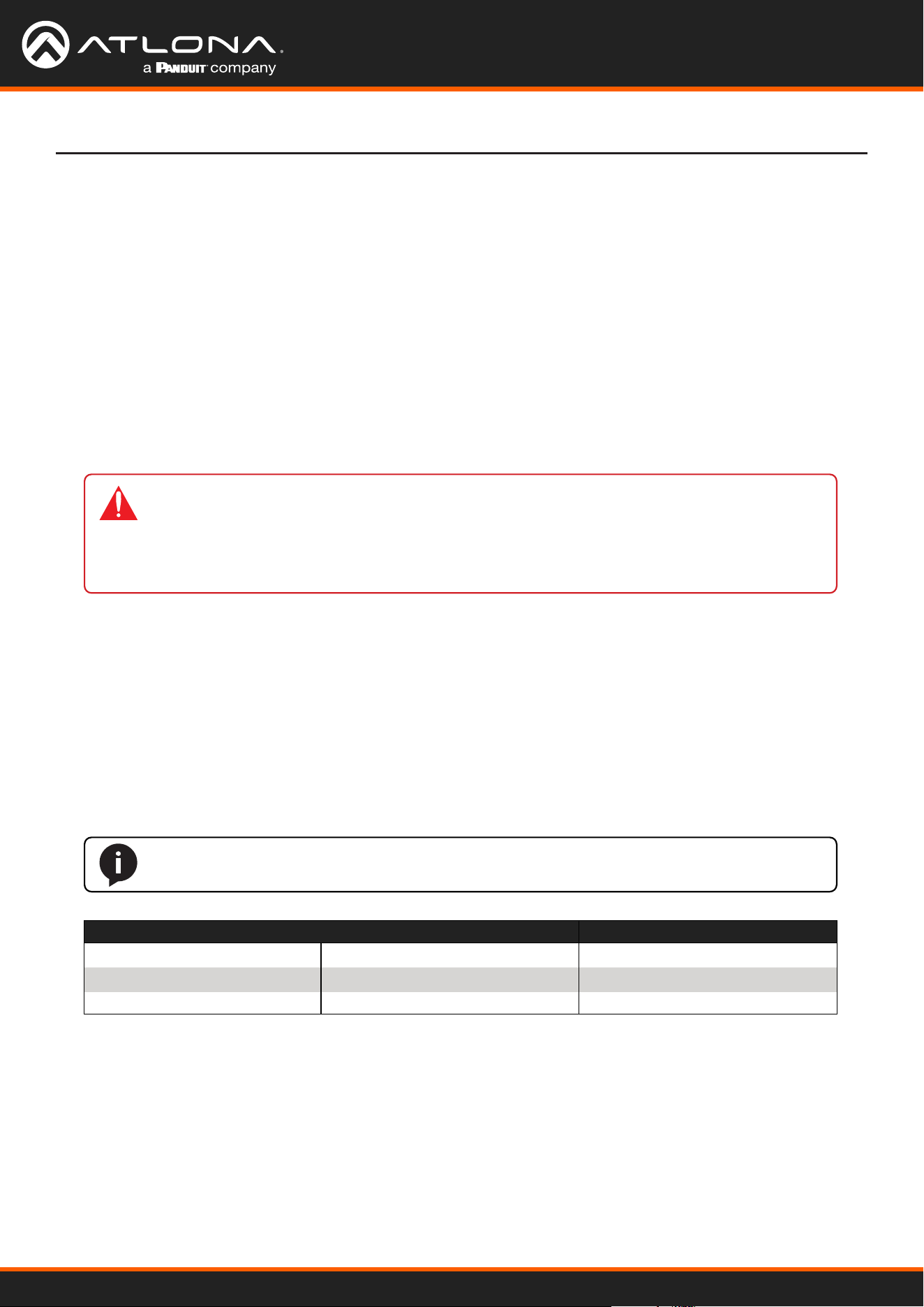
Using OmniStream
™
with Velocity
™
Device Manager
81
Device Operation
Fast Switching
1. Login to the decoder and click HDMI OUTPUT in the menu.
2. Click the Fast Switching Enable toggle switch to enable this feature. When enabled, the toggle switch will be
green.
3. Enter the timeout interval, in seconds, in the Fast Switching Timeout(s) eld. If fast switching is enabled and
the decoder is switched to a dierent stream, but the stream is not present, then the decoder will hold the last
image on the screen. This image will continue to be displayed until either a new stream appears or the decoder
is switched to a dierent stream. Once the timeout interval has expired, the screen will go black. Setting the
timeout interval to 0 disables this feature and the last image will be displayed indenitely.
The VCx codec provides fast switching at resolutions up to 4K @ 60 Hz. This is an improvement over the VC-2
codecs that limited fast switching to 1920x1200. When the decoder resolution and frame rate are set to Auto,
VCx fast switching operates at the preferred resolution and frame rate of the display. In some cases, this preferred
resolution and frame rate might not be the maximum supported by the display. If fast-switching is desired at a
supported resolution and/or frame rate other than the preferred resolution and frame rate, the decoder can be
manually congured for those resolutions.
The fast switching time depends primarily on three things, when switching between streams: resolution, frame rate,
and bitrate. For example, a 4K60 stream operating at 750 Mb/s requires ~250 ms to switch. On the other hand, a
1080p stream operating at 750 Mb/s requires less than 50 ms to switch. The time it takes to switch is determined by
the amount of time it takes for all the data for a complete frame to be received by the decoder. To improve the fast
switching time, decrease the resolution, lower the frame rate, or increase the bitrate.
NOTE: The following table is only applicable when using the VC-2 codec.
Input Resolution (from Encoder) Output Resolution (AT-OMNI-121) Output Resolution (AT-OMNI-122)
1280 x 720p 1280 x 720p 1280 x 720p
1920 x 1080p @ 60 Hz 1920 x 1080p @ 60 Hz 1920 x 1080p @ 30 Hz
> 1920 x 1080p (up to UHD) 1920 x 1080p @ 60 Hz 1920 x 1080p @ 30 Hz
IMPORTANT: If Fast Switching is enabled, latency increases from 0.5 frames to 1.5 frames.
When using Fast Switching mode, the output resolution will be 1920x1080p, regardless of the
source resolution. Also note that 1080i is not supported in Fast Switching mode. Also note that
Slate / Logo Insertion and Text Insertion will be automatically disabled when Fast Switching is
enabled.

Using OmniStream
™
with Velocity
™
Device Manager
82
Device Operation
Fast Switching FAQs
Question: Does fast switching work between streams of dierent resolutions?
Answer: Yes. Fast switching can be used between streams with dierent resolutions and frame rates.
Question: Does fast switching work between HDR and SDR streams?
Answer: Yes, fast switching can be used between HDR and SDR streams; however, it’s important to note that
some color artifacts may appear during the switch.
Question: Does fast switching work between single streams and multiviews or between multiviews?
Answer: No. Due to the way multiviews work, fast switching is not supported. However, it is not necessary to
change the fast switching setting – the decoder will switch as fast as possible between multiviews
and return to fast switching when single streams are used.
Question: Does fast switching work on video walls?
Answer: No. Fast switching is not supported when using video walls.
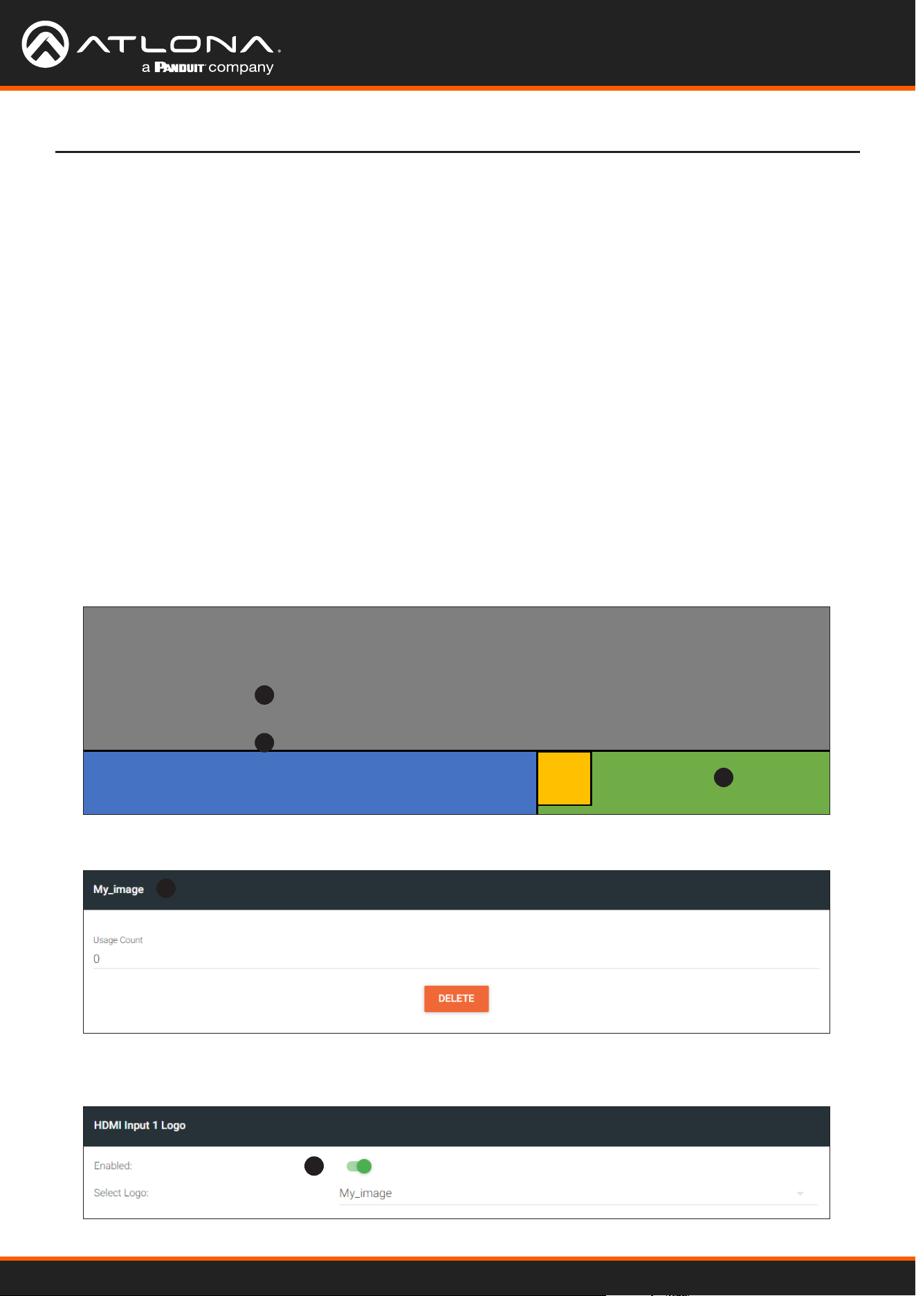
Using OmniStream
™
with Velocity
™
Device Manager
83
Device Operation
Slate / logo insertion is managed from within Velocity. The dierence between a “slate” and “logo” is in the size
of the image and how it is used: Logos are classied as smaller, low-resolution images that can be positioned at
specied locations on the screen. Slates occupy the entire screen. Note that while logos may be used as slates, the
image quality will be degraded, as the image will be scaled to ll the screen.
Slate / logo insertion can be performed on both the encoder and decoder. When congured on the encoder, the
image that is displayed on the output (decoder) will be from the encoder IP address(es) to which each decoder is
subscribed. When congured on the decoder, the image is unique to the specied HDMI output.
1. Go to the encoder, click OTHER in the menu bar, then enter the name of the image in the Name eld. If a name
is not specied, then the UPLOAD button will be disabled.
2. Under the New logo window group, click the Choose File button and select the image to be used. Only .png
les are valid selections.
3. Click the UPLOAD button to upload the le.
Slate / Logo Insertion
4. A new window group will be created with the name of the logo that was provided in Step 1.
Top Left
Bottom Left
Bottom Right
Center
Top Right
Adding Slates / Logos
1
4
2
3
Conguration as a Logo
5. Under the HDMI Input Logo window group, click the Enabled toggle switch to activate the logo/slate feature.
When enabled, this toggle switch will be green.
5
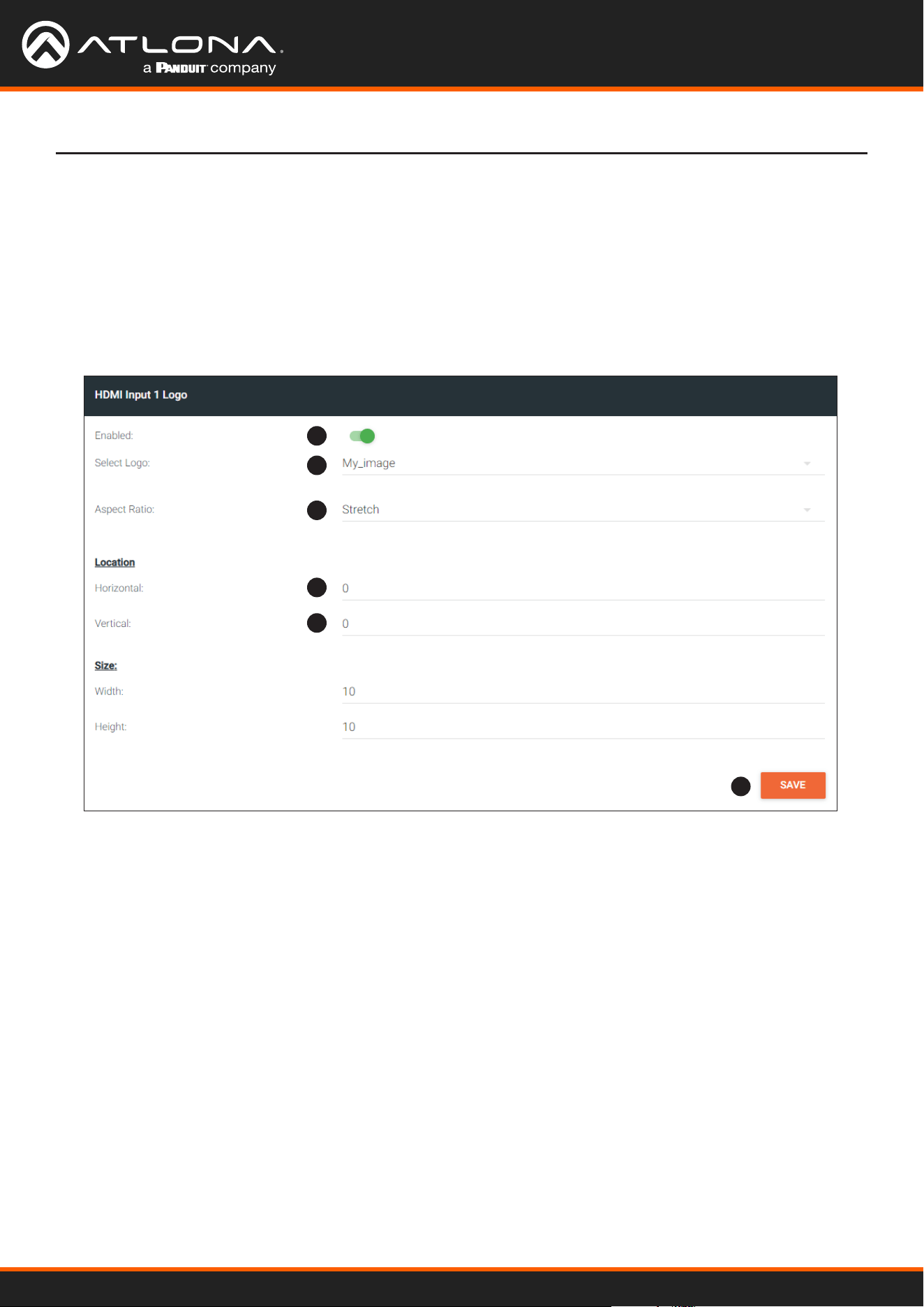
Using OmniStream
™
with Velocity
™
Device Manager
84
Device Operation
5
6
7
8
8
9
6. Click the Select Logo drop-down list and select the desired logo. To prevent the image from being displayed,
select the Not used option.
7. Click the Aspect Ratio drop-down list to set the aspect ratio of the image. Selecting Keep will maintain the
aspect ratio. Select Stretch to scale the image to ll the screen.
8. Enter the location of the on-screen image, in pixel values, by entering the desired values in the Horizontal and
Vertical elds.
9. Click the SAVE button to commit changes.
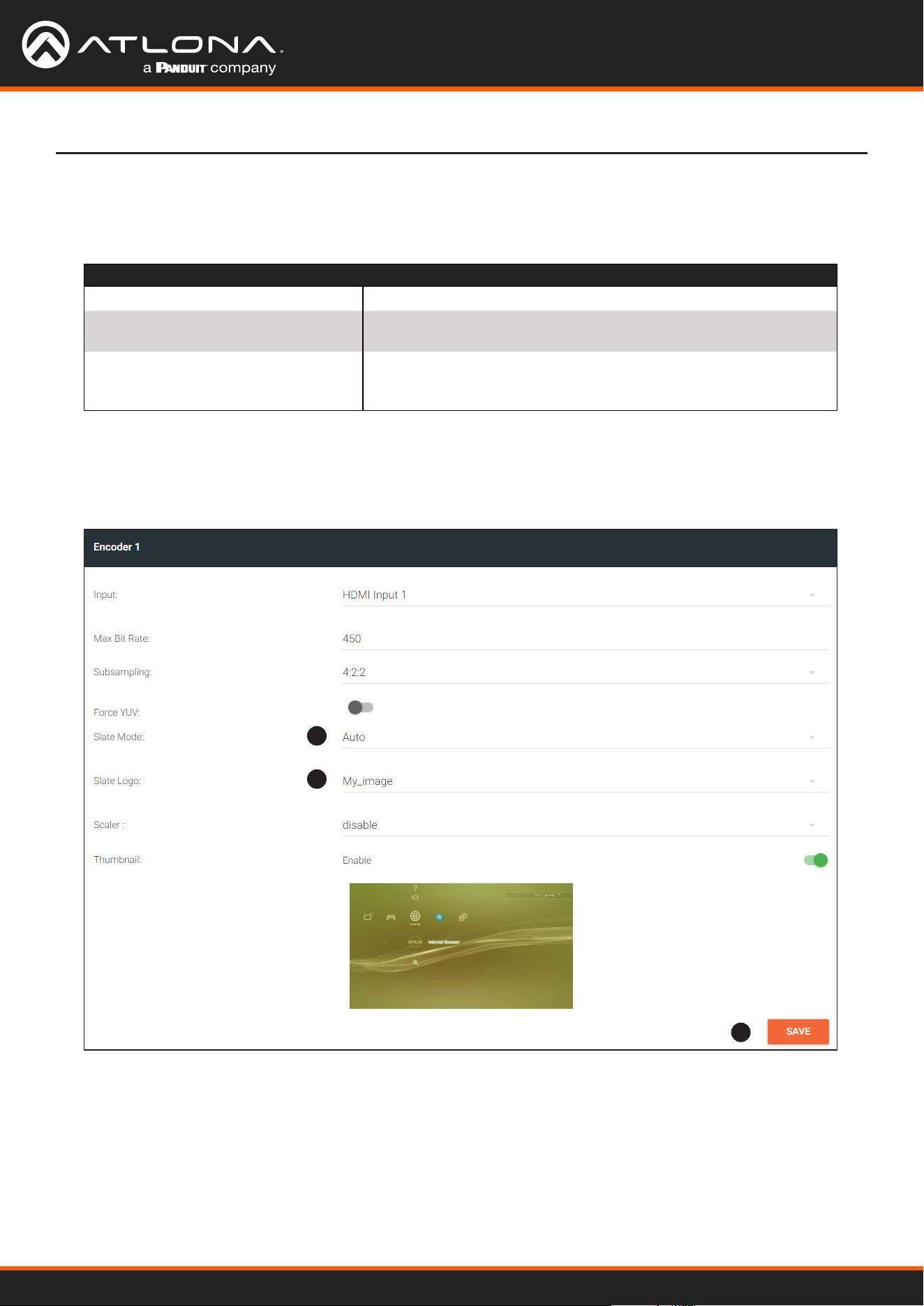
Using OmniStream
™
with Velocity
™
Device Manager
85
Device Operation
1
2
3
Mode Description
Off Disables the image from being displayed.
Manual The image will always be displayed, superimposed on the source
signal, and will remain even if the source signal is lost.
Auto The image will only be displayed when the source signal is lost.
For example, this mode is useful in conference room applications
for displaying system instructions when no sources are connected.
1. Upload the image as outlined in the previous section. Click INPUT in the menu bar, then go to the desired
encoder and click the Slate mode drop-down list. Select O, Manual, or Auto.
Conguration as a Slate
2. Click the Slate Logo drop-down list and select the desired image. Note that if Slate Mode is set to O, then this
eld will not be visible.
3. Click the SAVE button to apply all changes.

Using OmniStream
™
with Velocity
™
Device Manager
86
Device Operation
1. Click OTHER in the menu bar.
2. Click the DELETE button in the desired image window group. When the DELETE button is clicked, the window
group and the associated image will be deleted from the encoder. If the DELETE button is disabled, do the
following:
a. Locate the HDMI Input Logo window groups.
b. Click the Select Logo drop-down list and select Not Used.
c. Click the SAVE button.
d. Refresh the page.
e. Click the DELETE button to remove the logo.
Follow the instructions below to remove a logo/slate image.
Deleting Slates / Logos
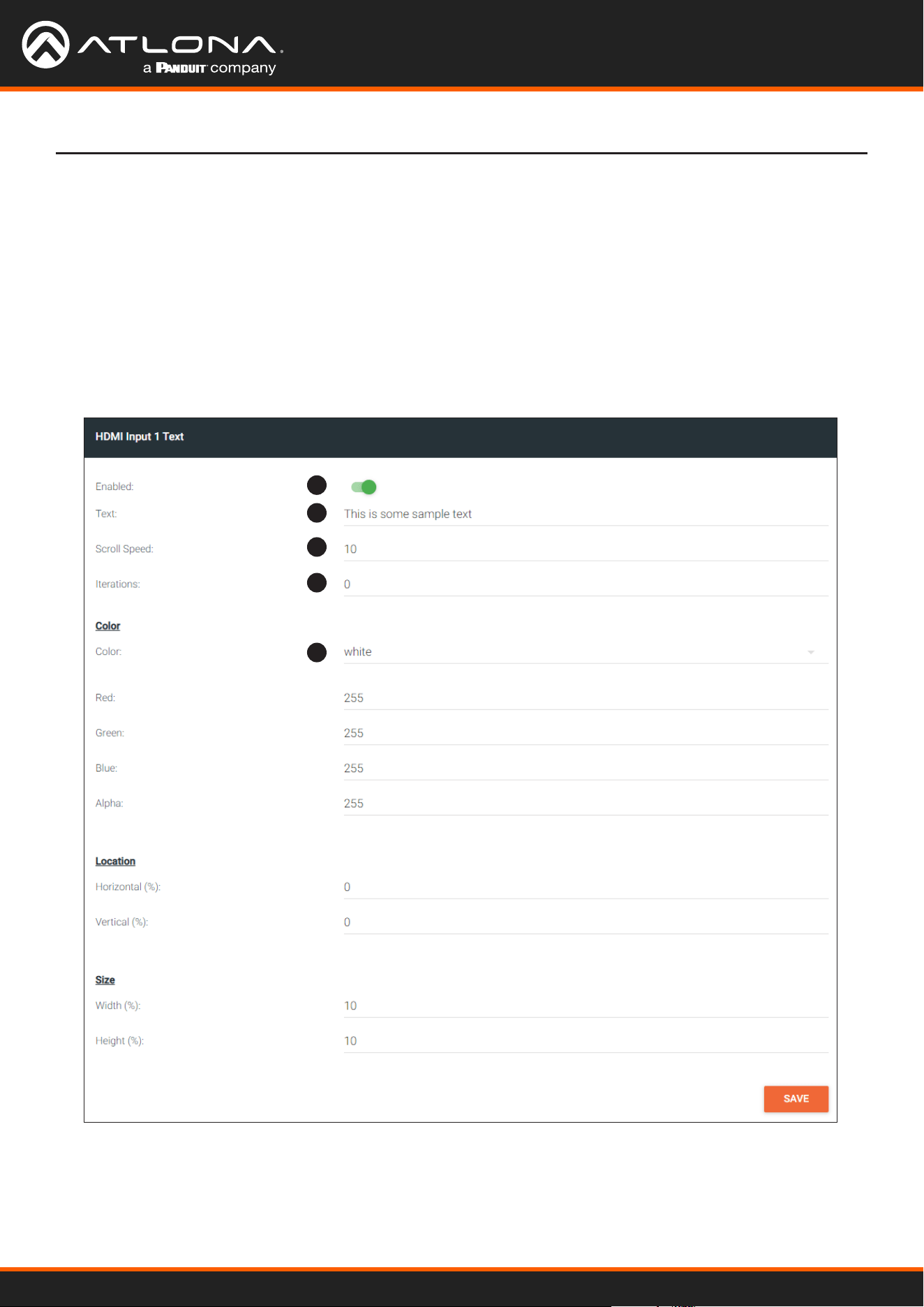
Using OmniStream
™
with Velocity
™
Device Manager
87
1. Go to the encoder, click OTHER in the menu bar, then click Text in the side menu bar. Click the Enabled toggle
switch under the desired HDMI Input Text window group. When enabled, this toggle switch will be green.
2. In the Text eld, enter the desired text.
3. Specify the speed of the scrolling text in the Scroll Speed eld. Values from -255 to 255 are valid.
Negative numbers will scroll the text from left to right. Positive numbers will scroll text from right to left.
4. Enter the number of iterations in the Iteration eld. Set this eld to 0 (zero) to set the number of iterations to
innity.
Text Insertion
Device Operation
1
2
3
4
5
5. Click the Color drop-down list to select the color of the text. The Red, Green, and Blue elds can be changed
to further modify the color of the text. Adjust the Alpha eld to control the transparency of the text. A value of
255 is opaque and a value of 0 is transparent. Numbers from 0 to 255 are valid for each of these elds.
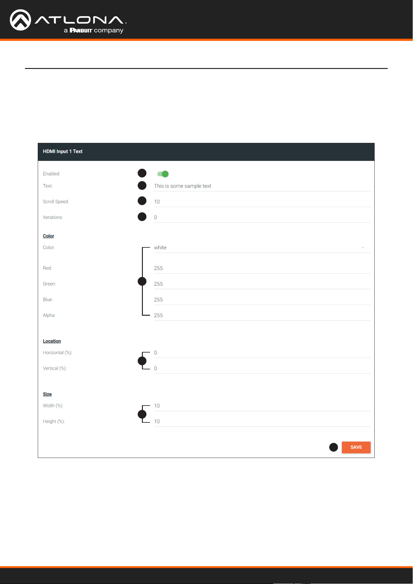
Using OmniStream
™
with Velocity
™
Device Manager
88
Device Operation
6. Specify the location of the text in the Horizontal (%) and Vertical (%) elds. Each of these values is based on
the horizontal and vertical resolution of the screen.
7. Specify the size of the text in the Width (%) and Height (%) elds. Each of these values is based on the
horizontal and vertical resolution of the screen.
8. Click the SAVE button to commit all changes.
1
2
3
4
8
5
6
7
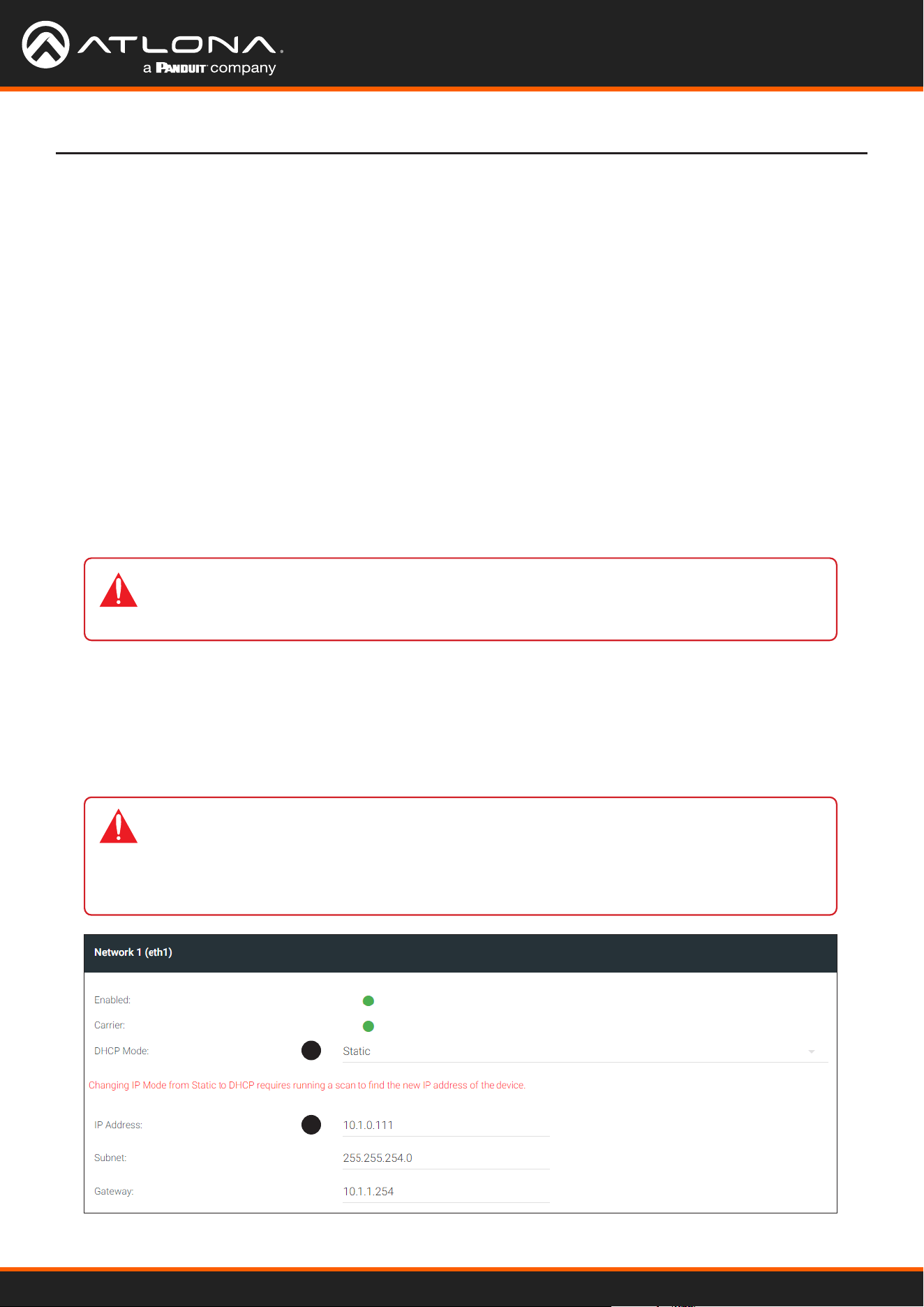
Using OmniStream
™
with Velocity
™
Device Manager
89
Conguring a Static IP Address
If an encoder is unable to recognize a DHCP server, within 60 seconds after being connected to a network,
the encoder is placed in Auto IP (APAPI) mode and assigned an IP address within the range 169.254.xxx.xxx.
In order for the encoder to be recognized on the network, it will need to be assigned a static IP address.
There will be situations where it is desirable for the encoder to be assigned a static IP address. Some IT
environments prefer this method, as opposed to having a DHCP server dynamically assign IP addresses. In other
cases, an encoder that is in Auto IP (APAPI) mode will need to have a static IP address assigned before it can be
connected to a network with a specied subnet.
IMPORTANT: Under Microsoft Windows, make sure to write down the current IP settings
in order to restore them, later. If Obtain an IP address automatically and Obtain DNS server
automatically are selected, then this step is not required.
Prepare the Encoder and the PC (Auto IP Mode only)
General Static IP Conguration
1. Go to the encoder/decoder, click NETWORK in the menu bar, then click the DHCP Mode drop-down list and
select Static.
2. Enter the desired IP address in the IP address eld.
• Make sure that the encoder is powered. Power will need to be supplied either by the external 48V power supply
(not included) or by connecting an Ethernet cable from the encoder to a PoE-capable switch.
• Connect an Ethernet cable from the PC, to one of the Ethernet ports on the encoder. If using the AT-OMNI-112,
the Ethernet cable can be connected to either ETHERNET 1 or ETHERNET 2 port.
• Congure the PC to a static IP address that is on the same subnet as the encoder.
Device Operation
1
2
IMPORTANT: Dual-channel encoders provide two Ethernet interfaces. It is important to
understand that even though they are separate physical interfaces, they should be congured
as a single interface. For example, if conguring the encoder in static mode, make sure both
Network 1 and Network 2 are congured with a static IP address. Network 1 and Network 2
should not be congured in dierent modes.
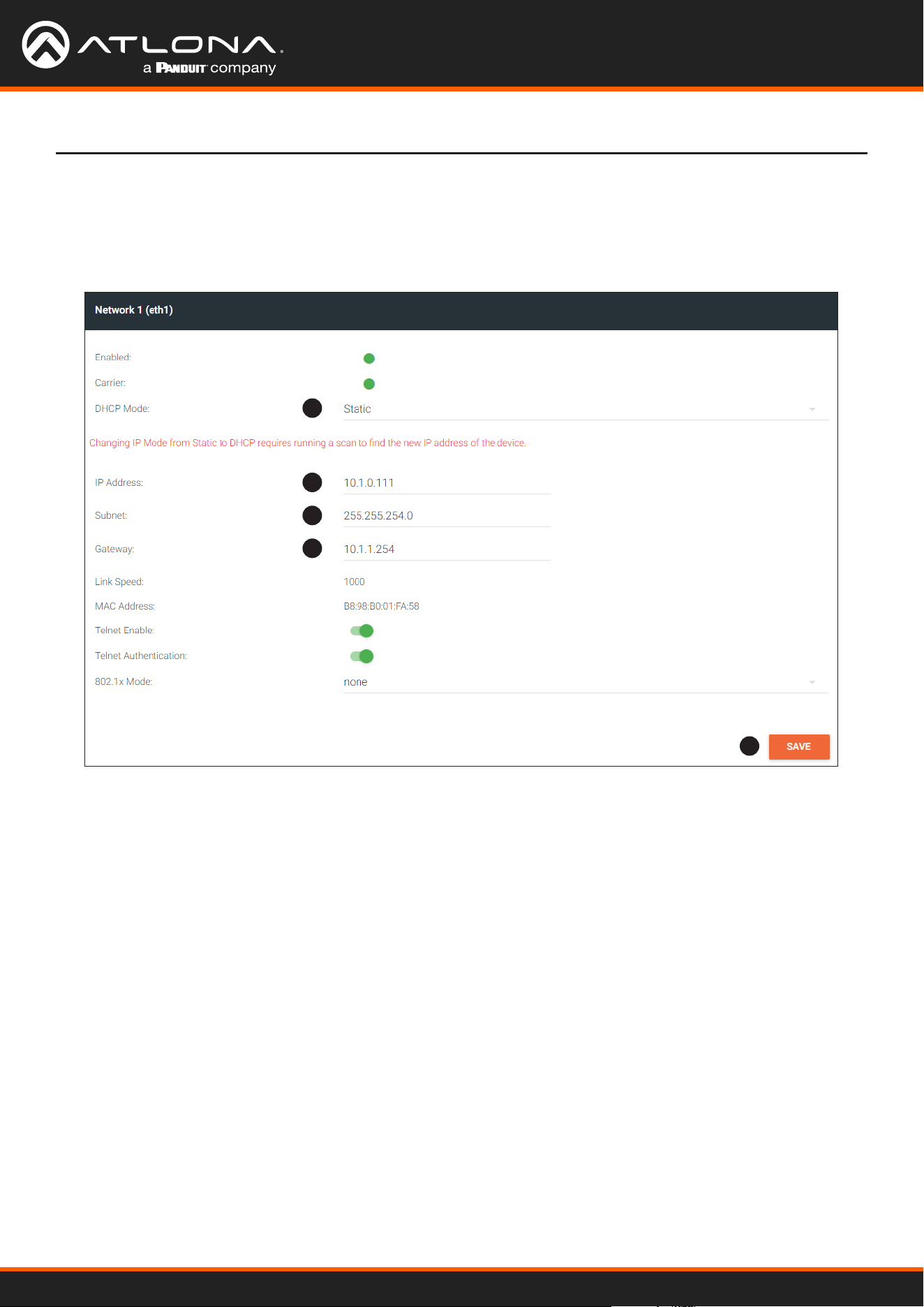
Using OmniStream
™
with Velocity
™
Device Manager
90
Device Operation
3. Enter the subnet mask in the Subnetmask eld.
4. Enter the gateway (switch/router) address in the Gateway eld.
5. Click the SAVE button to commit all changes.
1
2
3
4
5
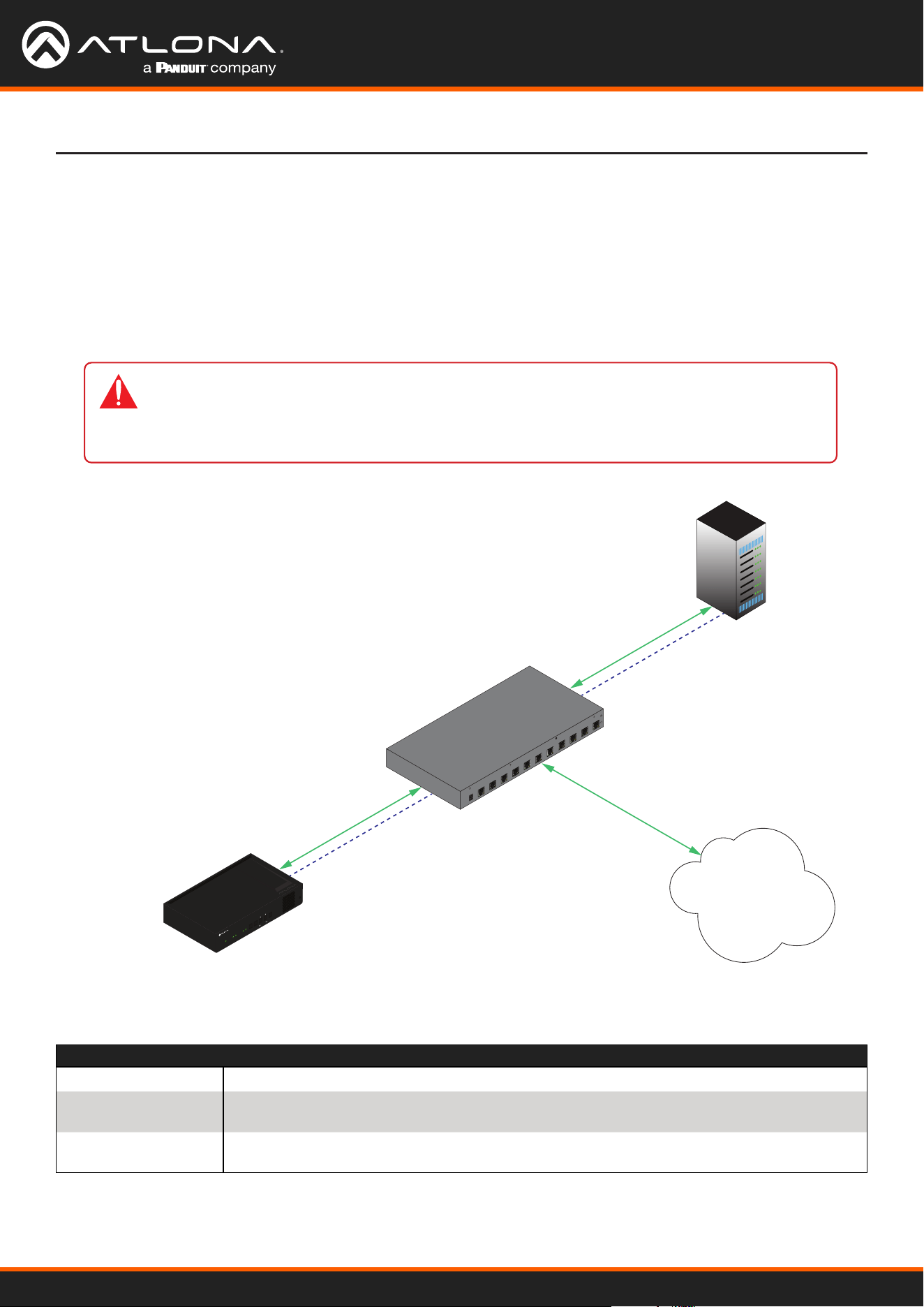
Using OmniStream
™
with Velocity
™
Device Manager
91
Device Operation
802.1X Authentication
802.1X is a server-based port authentication which restricts unauthorized (rogue) clients from connecting to a Local
Area Network through a public port. In its simplest form, 802.1X usually involves three parties: supplicant (client
device), authenticator (Ethernet switch or WAP), and an authentication server. Before the device is permitted on
the network, port communication is restricted to Extensible Authentication Protocol over LAN (EAPOL) trac. If the
device passes the authentication process, the authentication server noties the switch, allowing the client to access
the LAN. The illustration below shows the basic architecture.
Three options are available on both the OmniStream encoder and decoder.
Ethernet
(EAPOL)
EAP*
EAP
Ethernet
(RADIUS)
Ethernet
(Normal traffic)
Supplicant
(Encoder or Decoder)
Authenticator
(Switch)
* Extensible Authentication Protocol
Authentication
Server
LAN
HDMI
PWR
LINK
TM
O
MNI
S
TREAM
VOLUME
DISPLAY
INPUT
ID
1 2 1 2
Protocol Description
none 802.1X protocol disabled
PEAP/MSCHAPv2 Protected EAP; requires basic credentials in addition to a CA (certicate authority)
certicate.
EAP-TLS EAP Transport Layer Security; requires a client certicate, client private key, and CA
(certicate authority) certicate.
WARNING: Connecting an 802.1X-enabled encoder to a network without an active or
operational authentication server, will result in an encoder that does not function until the
expected message is returned from a RADIUS server. If it is unclear as to whether the network
uses 802.1X authentication, consult the IT administrator for assistance.
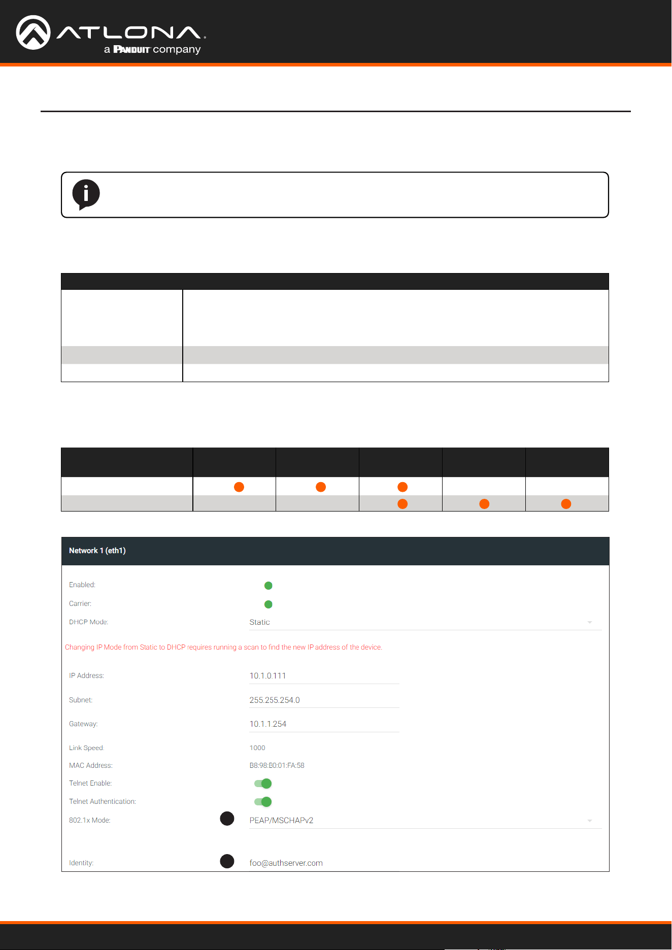
Using OmniStream
™
with Velocity
™
Device Manager
92
Device Operation
1. Go to the encoder/decoder, click NETWORK in the menu bar, then click the 802.1x Mode drop-down list and
select the desired authentication method. In the example below, PEAP/MSCHAPv2 is selected.
2. Once a method is selected, the required elds for that method will be displayed. Enter the required information
in each eld. For the PEAP/MSCHAPv2 option, the elds are described as follows:
1
2
Field Description
Identity Enter the identity of the authentication server in this eld. PEAP uses this eld to
identify the correct authentication server which will process the credentials. For
example, if [email protected] is entered, then this identies AUTHSERV as the
RADIUS (authentication) server.
Password Enter the password in this eld.
CA certificate Select the certication authority (CA) certicate.
NOTE: If using dual-channel encoders, both Network 1 (eth1) and Network 2 (eth2) will need
to be set up, depending upon the system requirements.
Authentication Method Identity Password CA Certicate CA Certicate Client Private
Certicate
PEAP/MSCHAPv2
EAP-TLS
Refer to the table below for a list of available authentication methods. An orange dot indicates that this eld will
be displayed as part of the method.
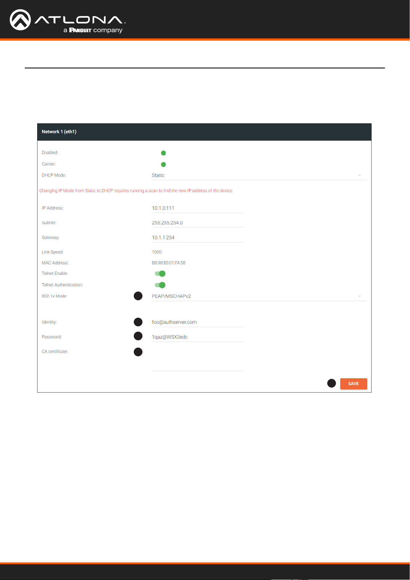
Using OmniStream
™
with Velocity
™
Device Manager
93
Device Operation
3. Enter the password in the Password eld.
4. Enter the certicate authority certicate in the CA certicate eld.
5. Click SAVE to commit changes.
1
2
3
4
5
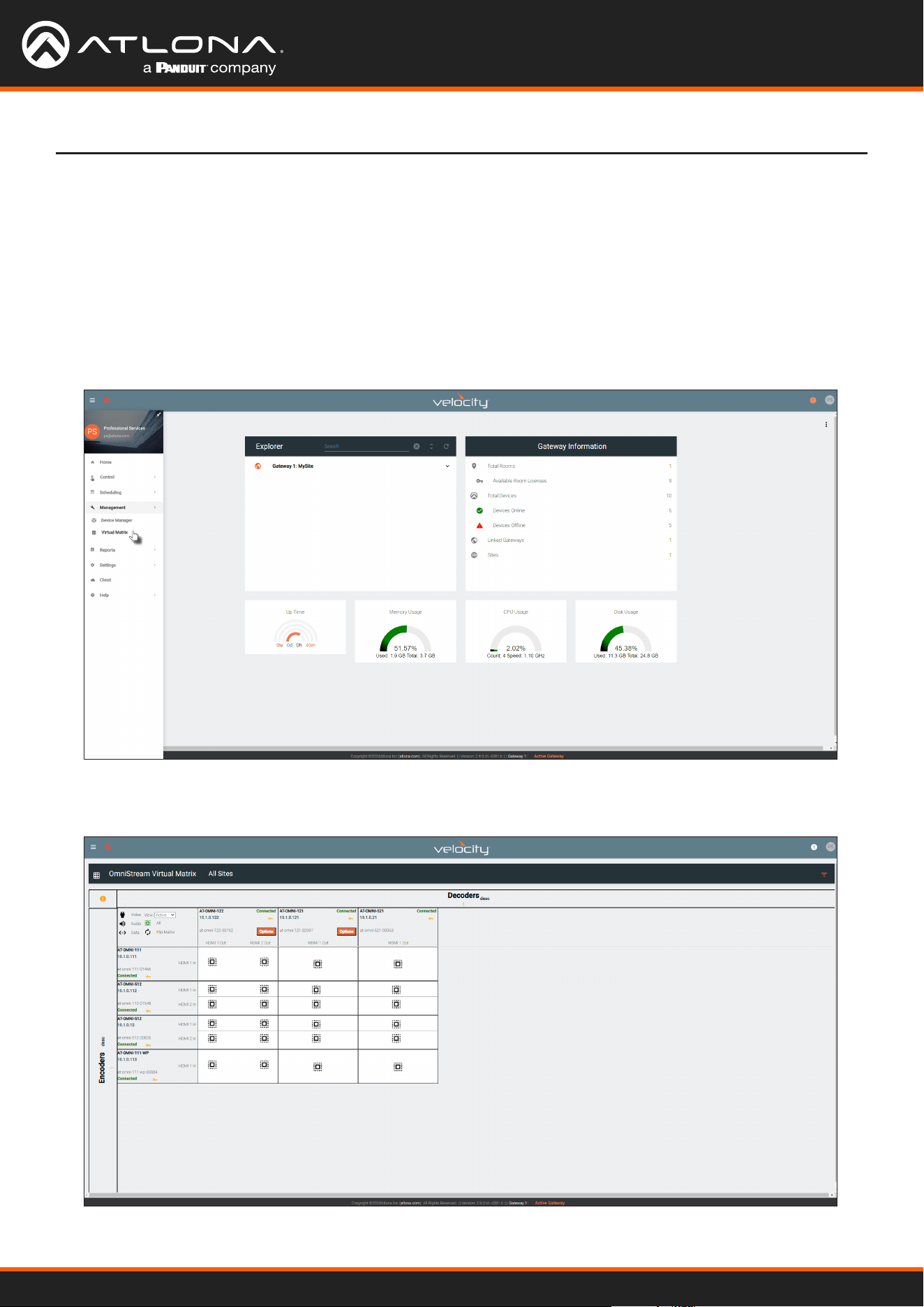
Using OmniStream
™
with Velocity
™
Device Manager
94
Device Operation
The OmniStream Virtual Matrix
The OmniStream Virtual Matrix oers an easy way to manage the routing of OmniStream devices. To access the
OmniStream Virtual Matrix, perform the following:
1. Click the hamburger button, at the top-left of the screen.
2. Click Management > Virtual Matrix.
3. The OmniStream Virtual Matrix page will be displayed.
Launching the OmniStream Virtual Matrix
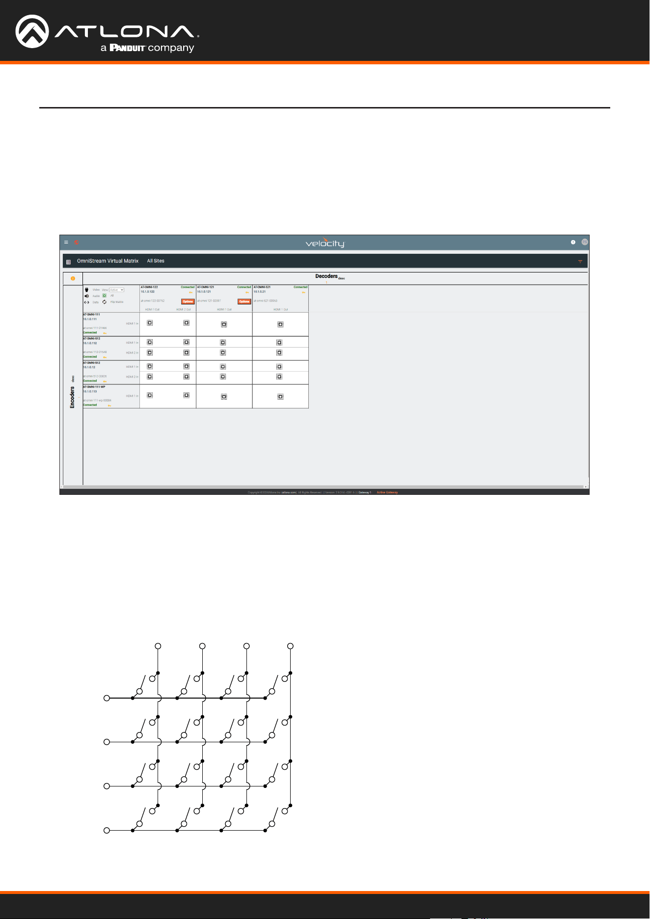
Using OmniStream
™
with Velocity
™
Device Manager
95
Device Operation
Layout and Operation
The illustration below shows multiple OmniStream units that are connected on the same network as the Velocity
Device Manager. The OmniStream Virtual Matrix is what is known as a crosspoint matrix. By denition, a crosspoint
matrix is a conguration that allows the routing of multiple input signals to various output destinations. In a
crosspoint matrix, each intersection (or crosspoint) between an input and an output can be controlled to connect
or disconnect signals, enabling exible signal distribution. This eliminates the need to change existing physical
connections.
ENCODER 1
SW1 SW2 SW3 SW4
SW5 SW6 SW7 SW8
SW9 SW10 SW11 SW12
SW13 SW14 SW15 SW16
DECODER 1 DECODER 2 DECODER 3 DECODER 4
ENCODER 2
ENCODER 3
ENCODER 4
To understand how a crosspoint matrix works, let’s duplicate a crosspoint matrix with a set of switch components.
The diagram below represents a basic 4x4 crosspoint matrix. Each endpoint is marked as either an ENCODER or a
DECODER, with encoders aligned along the rows and decoders along the columns. This arrangement mirrors the
layout used by the OmniStream Virtual Matrix. Note that all switches are open, meaning no encoder is currently
connected to any decoder. Each switch has been labeled.
Figure 1.1
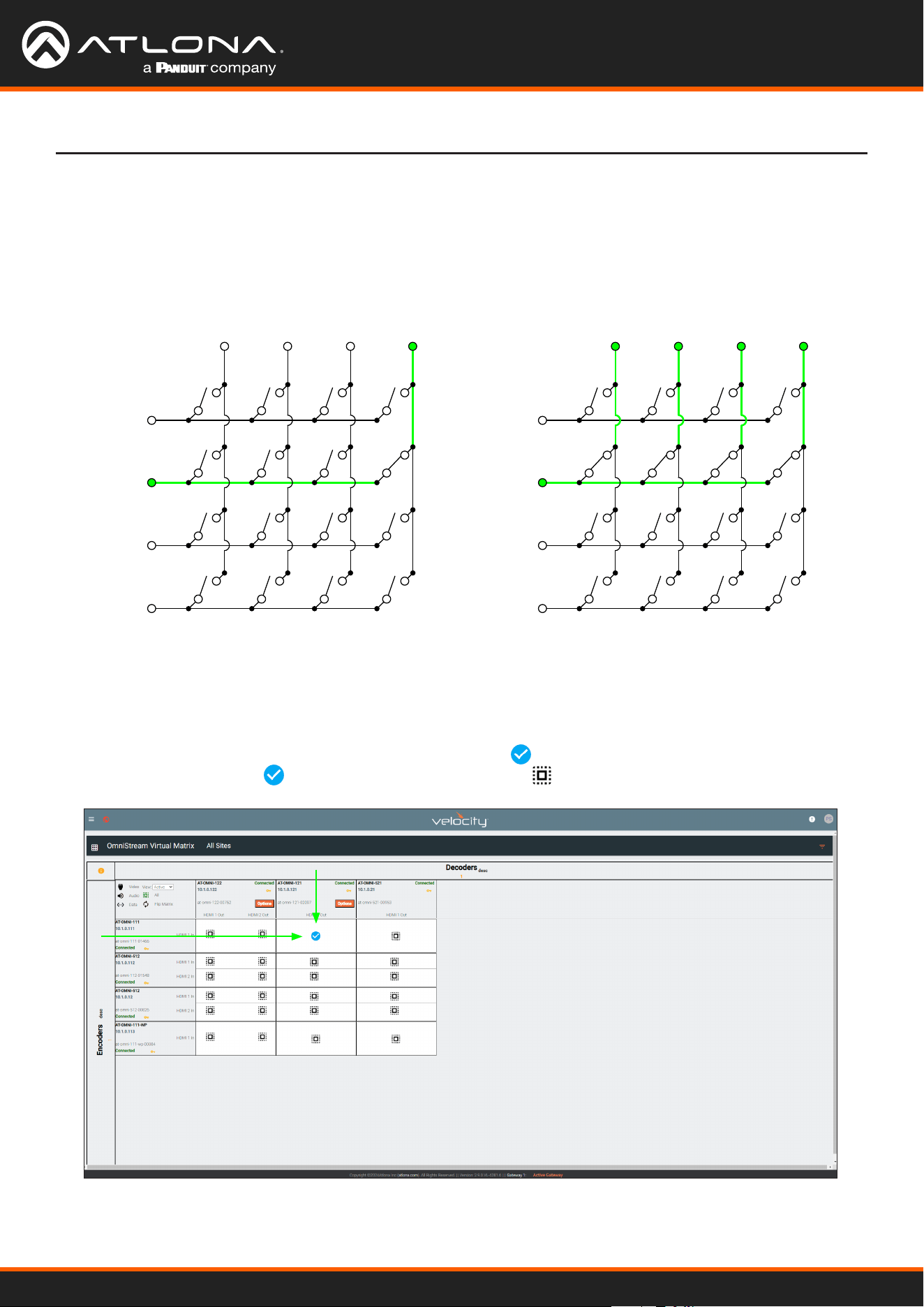
Using OmniStream
™
with Velocity
™
Device Manager
96
Device Operation
Next, let’s close one of the switches. In this example, closing switch SW8 will route the signal from ENCODER 2 to
DECODER 4. See Figure 1.2 for reference.
Furthermore, closing SW5, SW6, and SW7 will route the signal from ENCODER 2 to DECODER 1, DECODER 2, and
DECODER 3, as illustrated in Figure 1.3.
Note that routing a dierent source to a decoder that is already in use will display the new source signal.
For instance, in Figure 1.3, closing SW12 will route the signal from ENCODER 3 to DECODER 4, even though SW8 is
closed.
Returning to the OmniStream Virtual Matrix, in Velocity, the illustration below shows the source signal from the
AT-OMNI-111 encoder routed to the AT-OMNI-121 decoder. The icon indicates that these two devices are
communicating. Clicking the icon will disable the route and the icon will be displayed.
ENCODER 1
DECODER 1 DECODER 2 DECODER 3 DECODER 4
ENCODER 2
ENCODER 3
ENCODER 4
SW1 SW2 SW3 SW4
SW5 SW6 SW7 SW8
SW9 SW10 SW11 SW12
SW13 SW14 SW15 SW16
ENCODER 1
DECODER 1 DECODER 2 DECODER 3 DECODER 4
ENCODER 2
ENCODER 3
ENCODER 4
SW1 SW2 SW3 SW4
SW5 SW6 SW7 SW8
SW9 SW10 SW11 SW12
SW13 SW14 SW15 SW16
Figure 1.2 Figure 1.3
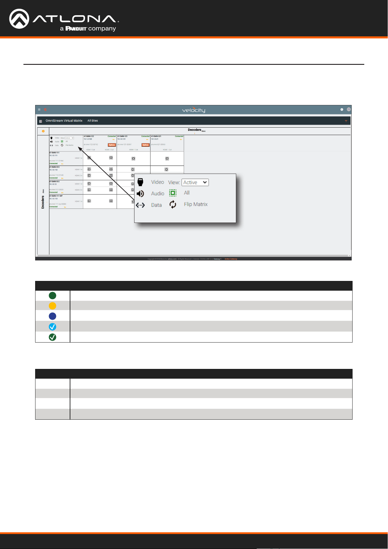
Using OmniStream
™
with Velocity
™
Device Manager
97
Device Operation
Icons and View Control
Located news the upper-left corder of the screen are a set of icons and a View drop-down list.
Click the View drop-down list to select the desired view.
Symbol Description
Video only.
Audio only.
Data only.
Partial crosspoint; not all signals are used.
Full crosspoint; all streams (video, audio, and data) are being used.
V
A
D
View Description
Active
Displays all active streams; this is the default view.
Primary
Displays only primary streams.
Backup
Displays only backup streams.
Control
Displays only control streams.
When these icons are clicked, the associated icons will be displayed in the rows and columns of the Virtual Matrix.
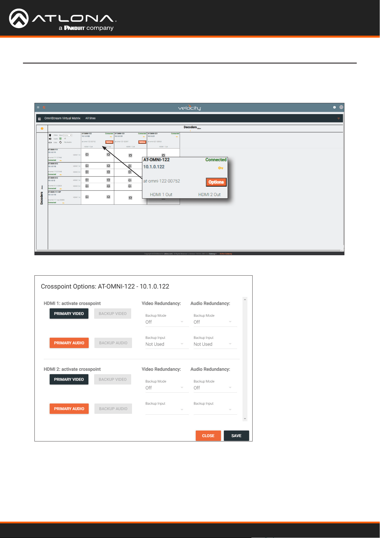
Using OmniStream
™
with Velocity
™
Device Manager
98
Device Operation
Options button
Click the Options button to display the stream conguration options.
Refer to HDMI OUTPUT page (page 130) page for details on primary and backup streams and redundancy.
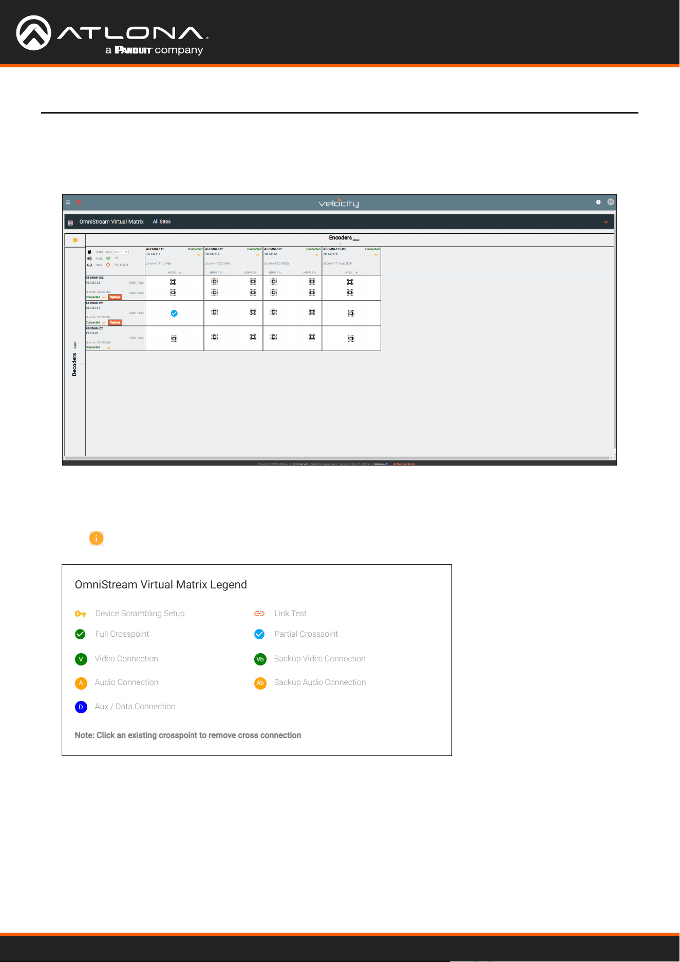
Using OmniStream
™
with Velocity
™
Device Manager
99
Legend
Click the icon, in the upper left-hand corner of the window to display the legend.
Flipping the Matrix
The OmniStream Virtual Matrix can be ipped. When ipped, the rows (encoders) will be displayed on the top as
columns and the columns (decoders) will be displayed on the side as rows. The ipped matrix is shown below.
Device Operation

Using OmniStream
™
with Velocity
™
Device Manager
100
The Velocity Interface
Encoders
Alias
Enter a name for the unit in this eld. This is optional.
Model
The model number of the unit.
Encoders Decoders
AT-OMNI-111 AT-OMNI-121
AT-OMNI-112 AT-OMNI-122
AT-OMNI-512 AT-OMNI-521
IP Address
Displays the IP address of the encoder.
MAC Address
Displays the MAC address of the encoder.
Firmware Version
The version of rmware that the OmniStream device is running. Always make sure the latest version of rmware is
installed.
FIRMWARE UPDATE
Click this button to update the rmware.
DEVICE INFO page

Using OmniStream
™
with Velocity
™
Device Manager
101
Description
Provides the option of assigning descriptive name to the unit.
Location
Provides the option of assigning a description of where the unit is located.
Timezone
Displays the time zone format. Click the SET TIMEZONE button, to assign the time zone.
Date/Time
Displays the current date and time. Click the SET DATE/TIME button to set these values.
Uptime
Displays the elapsed time since the unit was powered-on or rebooted.
System Temperature
Displays the ambient enlosure temperature.
Die Temperature
Displays the value returned from the die temperature sensor (DTS) on the chip of the PCB.
Power Consumption
Displays the precise power consumption of the encoder.
Hostname
Displays the hostname of the encoder. By default, OmniStream encoders are assigned a default hostname, which is
constructed as follows: at-omni-[SKU]-[last ve digits of MAC address].
NTP Server
Displays the NTP server. This eld is set to pool.ntp.org by default. Click this eld to enter the desired NTP
server address.
Buttons
Click this toggle switch to enable or disable the button backlight indicators on the front-panel.
LEDs
Click this toggle switch to enable or disable all front-panel LED indicators and button backlight indicators.
IDENTIFY
The Velocity Interface
System Mode
Click this drop-down list to select the system mode. The default setting is VCx.
Mode Description
VCx This is the default mode and represents the latest codec technology from Atlona, with
outstanding support for computer graphics and motion video. VCx includes support for
4K60 4:4:4 fast switching, dual streaming from AT-OMNI-111 encoders, and multiview on
the decoders.
VC-2 Video Legacy OmniStream codec that provides the best viewing experience when streaming
motion graphics and/or video.
VC-2 PC application Legacy OmniStream codec that optimizes the image when viewing static images, such
as spreadsheets or similar content.

Using OmniStream
™
with Velocity
™
Device Manager
102
The Velocity Interface
Option Description
None Checked Resets the encoder with no factory-default settings.
Reset User Resets the encoder to factory-default settings and resets custom user information.
Reset Network Resets the encoder to factory-default settings and resets network information.
FACTORY RESET
Click this button to reset the encoder to factory-default settings. When performing a factory reset, the following
options can be selected, by clicking the check box. If no options are selected, then the encoder is reset with no
factory-default settings.
Click this button to physically identify a unit on the network. Clicking this button will cause all front-panel LED
indicators to ash for 10 seconds.
DEBUG
Click this button to instruct the unit to create a debug le. This le is used by Atlona Technical Support Engineers to
diagnose internal issues with the unit.
REBOOT DEVICE
Click this button to perform a soft reboot of the OmniStream device.
SAVE
Click this button to commit changes to the settings on this page.
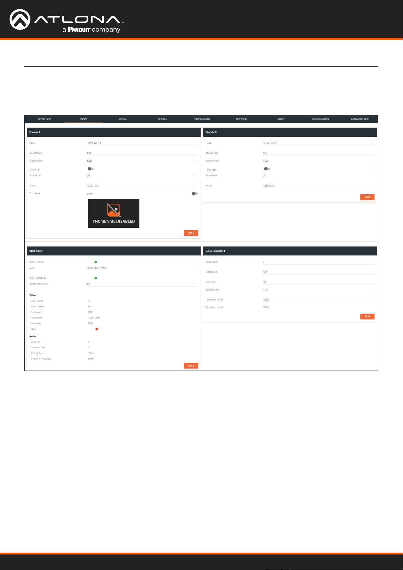
Using OmniStream
™
with Velocity
™
Device Manager
103
The Velocity Interface
The INPUT page provides signal information for each channel (input). Single-channel encoders will have two
encoder window groups.
Input
The selected input.
Max Bit Rate
Click this eld to enter the maximum bit rate. The default setting is 750 Mbps. 4K60 4:4:4 streams should be at
least 700 Mb/s, 4K30 4:4:4 streams should be at least 350 Mb/s, and 1080p streams should be at least 150 Mb/s.
Setting this eld below these recommended values will result in lower-quality video.
Subsampling
Click this drop-down list to select the chroma subsampling value. Available values are: 4:4:4, 4:4:2, and 4:2:0.
Encoder window group
INPUT page

Using OmniStream
™
with Velocity
™
Device Manager
104
The Velocity Interface
Force YUV
When this toggle switch is enabled (orange), the encoder will stream YUV content over the network, regardless of
which color space is used by the HDMI source. When the decoder receives the YUV stream, it will output YUV on
the HDMI output. However, if the decoder is connected to a display that requires RGB, as determined by the EDID
of the display, then the decoder will convert the video signal to RGB on the HDMI output. In order for the chroma
scaling to work on RGB inputs, this option must be enabled.
IMPORTANT: If decoders are congured to be used in a video wall application, then Force YUV
must be enabled.
Scaler
This feature is only available on the AT-OMNI-111. Click this drop-down list to select the desired output resolution.
This option is set to disabled by default. Resolutions in red are only available under the Encoder 1 window group.
Scaler Description
disable 1440x816
3840x2160 1280x736
2880x1524 1280x720
2592x1440 960x544
2560x1440 960x528
1920x1104 864x480
1920x1080 640x368
1920x1072 640x360
1792x960 480x272
1728x960
Thumbnail
Click this toggle switch to enable to disable a thumbnail of the input stream. When enabled, this toggle switch will
be green and an image of the input stream will be displayed. Thumbnails are updated every 2 seconds.
NOTE: Thumnails can also be accessed at: http://<encoder-ip-address>/thumbnail/
thumbnail1.jpg. For dual-channel encoders, the secondary thumbail can be accessed at:
http://<encoder-ip-address>/thumbnail/thumbnail2.jpg.
SAVE
Click this button to commit changes to the settings on this page.

Using OmniStream
™
with Velocity
™
Device Manager
105
The Velocity Interface
HDMI Input window group
Cable present
This indicator will be red if the encoder is unable to detect the source signal. This may indicate a damaged HDMI
cable. If this indicator is green (shown), then the cable integrity is good, and additional elds for both the Video and
Audio sections will be displayed.
EDID
Click this drop-down list to select the desired EDID. The default setting is Default HDR MCH.
EDID Description
Default HDR MCH Default EDID with HDR (3840x2160p30) and multichannel audio
Default HDR 2CH Default EDID with HDR (3840x2160p30) and two-channel audio
Default DV MCH Default EDID with Dolby Vision (3840x2160p30) and multichannel audio
Default DV 2CH Default EDID with Dolby Vision (3840x2160p30) and two-channel audio
Default SDR MCH Default EDID with SDR (3840x2160p30) and multichannel audio
Default SDR 2CH Default EDID with SDR (3840x2160p30) and two-channel audio
ATL 1080P 2CH 1920x1080p60 with two-channel PCM audio
ATL 1080P DD 1920x1080p60 with Dolby Digital
ATL 1080P DVI 1920x1080p60 formatted as DVI
ATL 1280x800 RGB DVI PCWXGADVI 1280x800 formatted as DVI
ATL 1280x800 RGB PCWXGA2CH 1280x800p60 PC format with two-channel PCM audio
ATL 1280x800 RGB TVWXGA2CH 1280x800p60 TV format with two-channel PCM audio
ATL 2160P 2CH 3840x2160p30 with two-channel PCM audio
ATL 2160P MCH 3840x2160p30 with multichannel PCM audio
ATL 2560x1600 2CH 2560x1600p60 with two-channel PCM audio
ATL 2560x1600 MCH 2560x1600p60 with multichannel PCM audio
ATL 720P DD 1280x720p60 with Dolby Digital audio
ATL 720P 2CH 1280x720p60 with Dolby Digital two-channel audio
ATL VR (2160x1200) 2160x1200p90 (Compatible with HTC VIVE® VR system)
HDCP Encrypted
Indicates if the content being transmitted from the source is HDCP-encrypted. If using HDCP-enctrypted content is
being used, then this indicator will be green.
Supported Version
Click this drop-down list to select the version of HDCP to be supported: 2.2, 1.4, or None. If None is selected,
then HDCP-enctrypted content cannot be passed-through.
The following Video elds will only be displayed if the Cable present indicator is green.
Color Depth
Displays the color depth of the source content.
Subsampling
Displays the chroma subampling value of the source
content.
Colorspace
Displays the color space of the source content.
Resolution
Displays the resolution of the source content.
Framerate
Displays the frame rate of the source content.
HDR
This indicator displays the presence of HDR source
content. If the indicator is green, then the source is
outputting HDR content. If the indicator is red, then no
HDR content is detected. Bit Depth
Displays the bit depth of the source audio.
Channel count
Displays the number of audio present that are present in

Using OmniStream
™
with Velocity
™
Device Manager
106
The Velocity Interface
The following Audio elds will only be displayed if the Cable present indicator is green.
Bit Depth
Displays the bit depth of the source audio.
Channel count
Displays the number of audio present that are present in
the source audio.
Format
Displays the audio format of the source content.
Frequency
Displays the audio frequency of the source content.
Video Generator window group
This signal can be used to test the video capability of the network. Single-channel encoders will have one Video
generator window group.
Color Depth
Click this drop-down list to select the color depth. Available values are 8, 10, and 12.
Colorspace
Click this drop-down list to select the color space. Available values are YUV and RGB.
Framerate
Click in this eld to change the frame rate (in Hz) of the video generator signal. The default value is 60.
Subsampling
Click this drop-down list to select the chroma subsampling value. Available values are 4:4:4, 4:4:2, and 4:2:0.
Resolution width
Click in this eld to change the horizontal resolution of the signal.
Resolution height
Click in this eld to change the vertical resolution of the signal.
SAVE
Click this button to save all changes under the Video generator window group.
SAVE
Click this button to commit changes to the HDMI Input window group.

Using OmniStream
™
with Velocity
™
Device Manager
107
The Velocity Interface
The Serial page provides serial port conguration when using control signals.
Supported Modes
Lists the supported protocols for the serial port.
Mode
Click this drop-down list to select the desired serial mode. Available values will be reected in the Supported
Modes eld.
Baud Rate
Click this drop-down list to select the desired baud rate: 115200, 57600, 38400, 19200, or 9600.
Data Bit
Click this drop-down list to select the number of data bits: 6, 7, or 8.
Parity
Click this drop-down list to select the parity bit: None, Odd, Even, Mark, or Space.
SERIAL page
Serial Port window groups
The following elds apply to both Serial Port window groups. Although single-channel encoders will also have two
Serial Port window groups, serial port 2 only supports IR.

Using OmniStream
™
with Velocity
™
Device Manager
108
The Velocity Interface
Stop
Click this drop-down list to select the stop bit: 1, 1.5, or 2.
SAVE
Click this button to save all changes under the Serial Port window group.
Serial Conguration window groups
The following elds apply to both Serial conguration window groups. The single-channel encoder will only have
one Serial conguration window group.
Port
Click this drop-down list to select the desired serial port.
Mode
Click this drop-down list to select the desired control mode. Available values are: cli and tcpproxy. Select
tcpproxy to send IP commands directly to the decoder, which are then output over RS-232 to the display (sink)
device. Selecting the cli option will pass through RS-232 data, directly from a control system, to the sink device
that is connected to the decoder.
SAVE
Click this button to commit all changes within the Serial conguration window group.
Command window groups
By default, window groups for the following commands are created: Display O, Display On, Volume Down,
and Volume Up.
Interpret on
Click this drop-down list to select the endpoint where the command will be processed: encoder or decoder.
ASCII
Enter the ASCII representation of the command string in this eld.
HEX
Enter the hexadecimal representation of the command in this eld.
NOTE: When entering the command string, it is not required to enter the string under both the
ASCII and HEX fields. The encoder requires that one field be completed.
SAVE
Click this button to commit all changes within the Command window group.
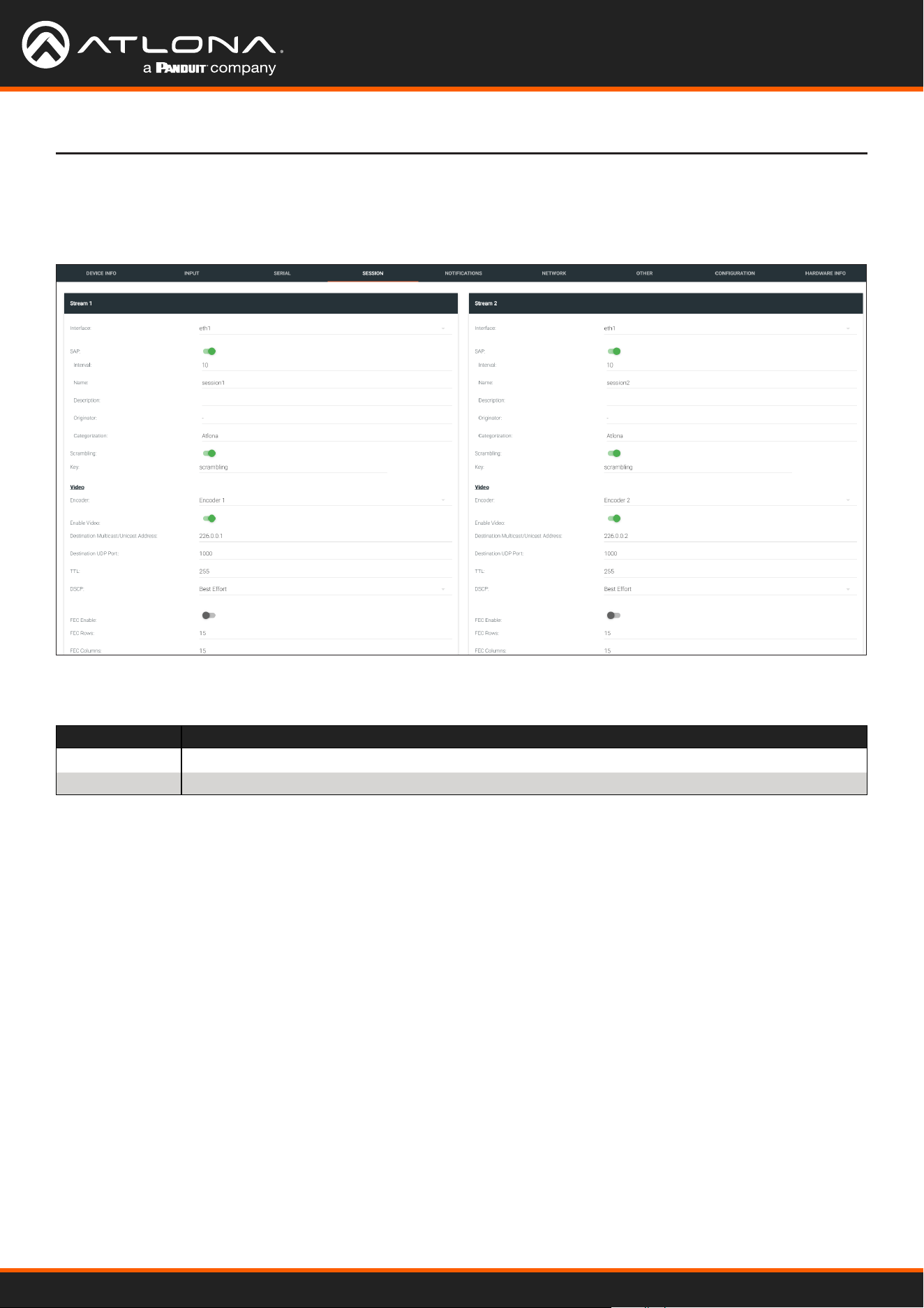
Using OmniStream
™
with Velocity
™
Device Manager
109
The Velocity Interface
The following elds apply to all Stream window groups. Both the dual-channel and single-channel encoders have
support for up to six Stream window groups.
SESSION page
Interface
Click this drop-down list to select the desired interface.
Interface Description
eth1 ETHERNET 1 port
eth2 ETHERNET 2 port (AT-OMNI-112 only)
SAP
Click this switch to enable or disable the Session Announcement Protocol. When enabled, the toggle switch will be
orange.
Interval
Sets the announcement interval.
Name
The name of the SAP session. By default, this is the same as the session name.
Description
The SAP description.
Originator
The ID of the SAP message originator.
Categorization
The SAP category. This eld can be changed, if desired.

Using OmniStream
™
with Velocity
™
Device Manager
110
Scrambling
Click this toggle switch to enable or disable scrambling on the encoder. Atlona recommends enabling scrambling for
security purposes. When enabled, the toggle switch will be green.
Key
This eld is only displayed if the Scrambling toggle switch is enabled (green). Enter the scrambling key in this eld.
The scrambling key must be ASCII and must contain a minimum of eight characters. Special characters and spaces
are not permitted.
The Velocity Interface
Video
Audio
Encoder
Click this drop-down list to select the encoder input.
Enable Video
Click this toggle switch to enable or disable the video signal. When enabled (green), video will pass from the encoder
to the decoder.
Destination Multicast/Unicast Address
Enter the IP address that will be used to stream the content.
Destination UDP Port
Enter the destination UDP port in this eld.
TTL
Set the TTL (Time-To-Live) duration, from 1 to 255 seconds, in this eld. The default value is 255 seconds.
DSCP
Click this drop-down list to select the DSCP value. Refer to Dierentiated Services Code Point (page 152) for more
information on this topic.
FEC Enable
Click this toggle switch to enable (orange) or disable Forward Error Correction (FEC). This feature can be used when
transporting streams over a network that is suspected to be unreliable, due to noise or other factors. By default, this
feature is enabled. Refer to FEC Details (page 150) for more information.
FEC Rows
Specify the number of FEC rows in this eld. Refer to FEC Details (page 150) for more information.
FEC Columns
Specify the number of FEC columns in this eld. Refer to FEC Details (page 150) for more information.
LINK TEST
Click this button to perform a link integrity test. This feature validates the quality of the link between the encoder
and decoder. Link tests are initiated at an encoder, and any decoders that are congured to join that encoder’s video
multicast address will return packet loss statistics to the encoder, which displays the combined results under the
Notications tab. Refer to Performing a Link Test (page 147) for more information.
Source
Click this drop-down list to select the desired input.
Enable AES67
Click this toggle switch to enable AES67. When this feature is enabled, the toggle switch will be green.

Using OmniStream
™
with Velocity
™
Device Manager
111
The Velocity Interface
Downmixing
This eld will only be available when AES67 is enabled. Available values are: none, mono, and stereo.
Enable Audio
Click this toggle switch to enable or disable the audio signal. When enabled (orange), audio will pass from the
encoder to the decoder.
Destination Multicast/Unicast Address
Enter the IP address that will be used to stream the content.
Destination UDP Port
Enter the destination UDP port in this eld.
TTL
Set the TTL (Time-To-Live) duration, from 1 to 255 seconds, in this eld. The default value is 255 seconds.
DSCP
Click this drop-down list to select the DSCP value. Refer to Dierentiated Services Code Point (page 152) for more
information on this topic.
FEC Enable
Click this toggle switch to enable (orange) or disable Forward Error Correction (FEC). This feature can be used when
transporting streams over a network that is suspected to be unreliable, due to noise or other factors. By default, this
feature is enabled. Refer to FEC Details (page 150) for more information.
FEC Rows
Specify the number of FEC rows in this eld. Refer to FEC Details (page 150) for more information.
FEC Columns
Specify the number of FEC columns in this eld. Refer to FEC Details (page 150) for more information.
Control/Serial
Source
Click this drop-down list to select the method of how commands are transmitted.
Source Description
Not Used Serial control is disabled
Commands Commands are sent using CEC (over HDMI)
Serial Port 1 Commands are transmitted using Serial Port 1
Serial Port 2 Commands are transmitted using Serial Port 2
Enable Aux
Click this toggle switch to enable or disable the AUX signals. When enabled (green), control signals will pass from
the encoder to the decoder.
Destination Multicast/Unicast Address
Enter the IP address of the decoder that will be receiving the control signals.
Destination UDP Port
Enter the destination UDP port in this eld.
TTL
Set the TTL (Time-To-Live) duration, from 1 to 255 seconds, in this eld. The default value is 255 seconds.

Using OmniStream
™
with Velocity
™
Device Manager
112
The Velocity Interface
DSCP
Click this drop-down list to select the DSCP value. Refer to Dierentiated Services Code Point (page 152) for more
information on this topic.
Bidirectional
Click this toggle switch to enable or disable bidirectional control. When enabled (green), control signals will be able
to pass from encoder to decoder, or from decoder to encoder.
Listen Port
Enter the listening port in this eld.
Enable Encoder Group
Click this toggle switch to enable (orange) or disable encoder grouping.
Group Name
Enter the name of the encoder in this eld. Only available if encoder grouping is enabled.
Active
Indicates if the encoder group is active. If active, then this indicator will be green. Only available if encoder grouping
is enabled.
Trigger
Click this drop-down list to select the trigger type: manual or input connected. Only available if encoder
grouping is enabled.
Mode Description
manual Use this setting to manually enable the input. When set to manual, click the Activate button to
perform the input switching.
input connected Use this setting to allow the encoder group to use automatic input detection. Once a new source
is connected, that source becomes the active source.
Encoder Groups
ACTIVATE
Click this button to activate the encoder group.
Members
This eld lists all members (encoder IP addresses) that have been added to the group. Use the Add button to add
members to the group.
ADD
Click this button to add the IP address of an encoder to the group. Note that when adding encoders to the group,
the IP address of the encoder, which is being used to create the group, must be included.
SAVE
Click this button to commit all changes within the Stream window group.
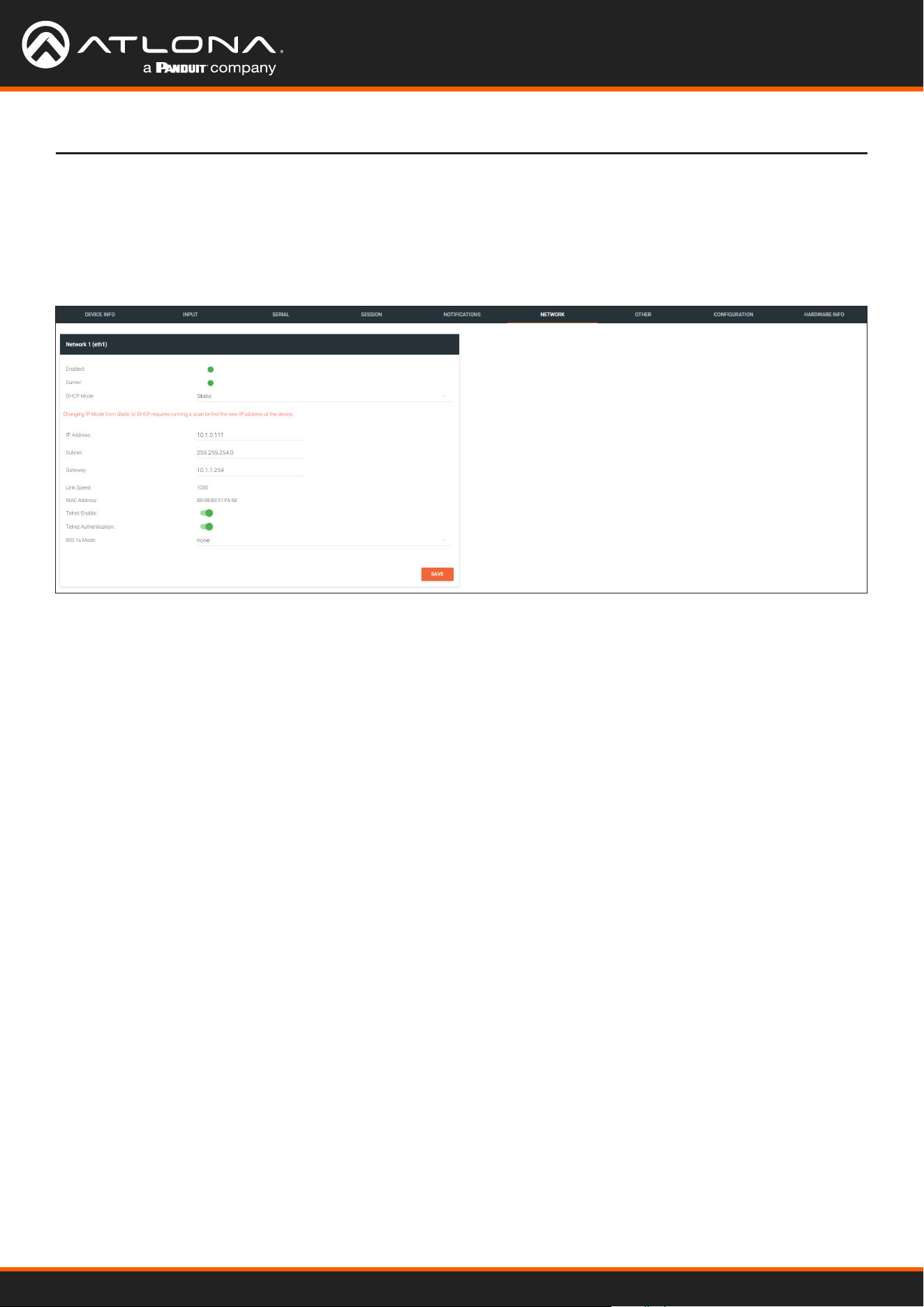
Using OmniStream
™
with Velocity
™
Device Manager
113
The Velocity Interface
The NETWORK page provides the ability to enable or disable DHCP mode for each video channel. When DHCP
mode is disabled, the IP address, subnet mask, and gateway must be provided. If using the dual-channel version,
then the information on both Channel 1 and Channel 2 are provided. This screen is identical to the NETWORK page
for the decoder.
NETWORK page
Enabled
This indicator displays whether or not the video stream for this channel is active. If the indicator is green, then the
video stream is active.
Carrier
If this indicator is green, then an active link exists. Otherwise, if no link exists, this indicator will be red.
DHCP Mode
Click this drop-down list to select the desired IP mode. Select DHCP to let the DHCP server (if present) assign the
encoder the IP settings; Subnet and Gateway elds will automatically be populated. When static is selected, the
information for the IP Address, Subnet, and Gateway elds must be entered.
IP Address
Displays the IP address used by the channel. This eld can only be changed if Mode is set to static.
Subnet
Displays the subnet mask for the channel. This eld can only be changed if Mode is set to static.
Gateway
Displays the gateway (router) address for the channel. This eld can only be changed if Mode is set to static.
Link speed
Displays the Ethernet interface link speed in Mbps. This eld cannot be modied.
MAC address
Displays the MAC address of the Ethernet interface.

Using OmniStream
™
with Velocity
™
Device Manager
114
The Velocity Interface
Telnet Enable
Click this toggle switch to enable or disable Telnet. If disabled, then Telnet sessions to the encoder cannot be
established.
Telnet Authentication
Click this toggle switch to enable or disable Telnet authentication. If enabled, then the toggle switch will be orange.
Once enabled, connecting to the encoder using Telnet will require login credentials. The default credentials are:
Username: admin
Password: Atlona
802.1x Mode
Click this drop-down list to select the desired authentication mode.
Protocol Description
none 802.1X protocol disabled
PEAP/MSCHAPv2 Protected EAP; requires basic credentials in addition to a CA (certicate authority)
certicate.
EAP-TLS EAP Transport Layer Security; requires a client certicate, client private key, and CA
(certicate authority) certicate.
SAVE
Click this button to commit all changes within the Network window group.
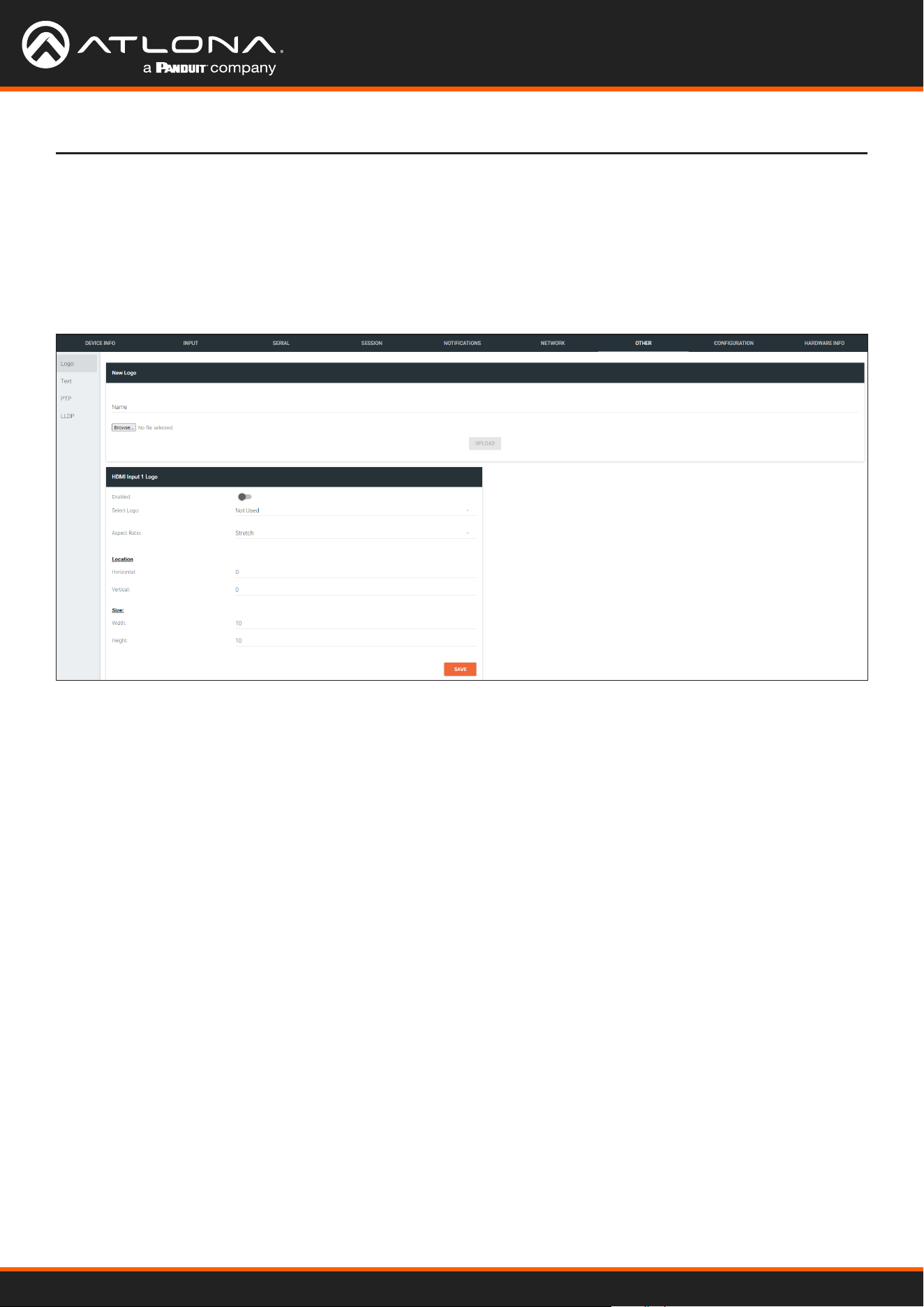
Using OmniStream
™
with Velocity
™
Device Manager
115
The Velocity Interface
The Other page provides logo/slate, text, and PTP management. Click the menu in the upper-left corner of the
Velocity screen to switch between Logo, Text, and PTP screens.
The Logo page provides the ability to upload a custom logo. This logo will be displayed when no video signal is
detected. Separate logos can be uploaded: one for each channel. Refer to Slate / Logo Insertion (page 83) for
more information on these settings.
OTHER > LOGO page
New Logo window group
HDMI Input Logo window group
Name
Enter a name for the logo in this eld.
Browse...
Click this button to select the logo le to be uploaded. Files must be in .png format and must not exceed 5 MB
(5120000 bytes) in size. When an image le is uploaded, it will appear in the Logo drop-down list.
UPLOAD
Click this button to upload the logo le to the encoder.
Enabled
Click the toggle switch to enable or disable the logo. If the toggle switch is green, then the logo will be enabled.
Logo
Click this drop-down list to select the desired logo. To disable the use of a logo, set to Not Used.
Aspect Ratio
Click this drop-down list to select the type of aspect ratio to be applied to the logo.

Using OmniStream
™
with Velocity
™
Device Manager
116
The Velocity Interface
Horizontal
Enter the horizontal position of the logo on the screen. This value is based on the total horizontal resolution of the
screen.
Vertical
Enter the vertical position of the logo on the screen. This value is based on the total vertical resolution of the screen.
Width
Enter the width of the logo. This value is based on the total horizontal resolution of the screen.
Height
Enter the height of the logo. This value is based on the total vertical resolution of the screen.
SAVE
Click this button to commit all changes within the HDMI Input window group.
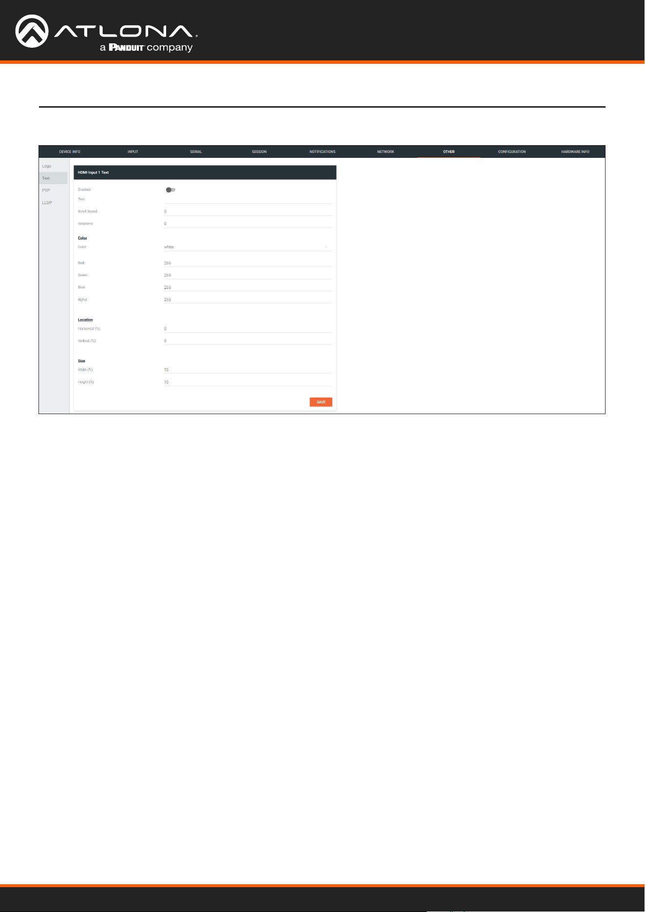
Using OmniStream
™
with Velocity
™
Device Manager
117
The Velocity Interface
OTHER > TEXT page
HDMI Input Text window group
Enabled
Click this toggle switch to enable or disable the text. When the toggle switch is orange, the text will be enabled.
Text
Enter the desired text in this eld.
Scroll Speed
Enter the scrolling speed in this eld. Integer values from -255 to 255 are valid. Negative numbers will scroll the
text from left to right. Positive numbers will scroll text from right to left.
Iterations
Enter the number of iterations in the Iteration eld. Set this eld to 0 (zero) to set the number of iterations to innity.
Color
Click this drop-down list to select a solid color preset: red, green, black, white, yellow, or blue.
Red, Green, Blue, Alpha
Click these elds to ne tune the color of the text. Integer values from 0 to 255 are valid for all elds. Adjust the
Alpha eld to control the transparency of the text. An alpha value of 255 is opaque and a value of 0 is transparent.
Horizontal
Enter the horizontal position of the text in this eld.
Vertical
Enter the vertical position of the text in this eld.
Width
Enter the width of the text in this eld. This value is
based on the horizontal resolution of the screen.
Height
Enter the height of the text in this eld. This value is
based on the vertical resolution of the screen.
SAVE
Click this button to commit all changes within the HDMI
Input Text window group.

Using OmniStream
™
with Velocity
™
Device Manager
118
The Velocity Interface
OTHER > PTP page
Network window group
The PTP page provides options for adjust Precision Time Protocol (PTP) for AES67 audio streams. PTP is used by
AES67 to keep all audio streams synchronized.
For a system utilizing PTP, all devices undergo an automatic self-election process to choose the interface to be used
as the PTP grandmaster (GM) clock, based on the accuracy of the device’s clock and the device’s congured priority.
A lower priority number means the unit is more likely to get selected as the GM.
IMPORTANT: If a new device is added to the network and the GM changes, a brief outage will
be experienced while all connected devices synchronize with the new clock. Because of this,
Atlona recommends that one unit gets manually dened as the GM and have both Priority 1
and Priority 2 elds be set to 1.
Domain Number
Enter the domain number in this eld. Valid entries are 0 through 127.
Priority 1
Enter the priority number in this eld.
Priority 2
Enter the priority number in this eld.
Is GM
This indicator displays the existence of a grandmaster clock for the specied PTP domain number. If the indicator is
green, then the grandmaster clock exists on this interface.
GM Identity
The grandmaster clock identity. If this eld is blank, then it means that this interface is the grandmaster clock.
Master Oset
Displays the grandmaster clock oset.
SAVE
Click this button to commit all changes the Network window group.

Using OmniStream
™
with Velocity
™
Device Manager
119
The Velocity Interface
OTHER > LLDP page
eth window group
The Link Layer Discovery Protocol (LLDP) page returns information about the switch that the encoder is connected
to. If both interfaces from a dual-channel encoder are connected to the switch, then two eth window groups will be
displayed.
NOTE: LLDP must be enabled on the switch that the encoders are connected to, in order for
the switch information to be displayed.
Via
The discovery protocol being used.
RID
The router ID.
Age
Up-time of the interface.
Chassis ID
The MAC address of the interface.
Chassis Capability
Indicates the device function, such as bridge (switch), router, etc.
Port ID
The port ID.
TTL
The Time-To-Live value.
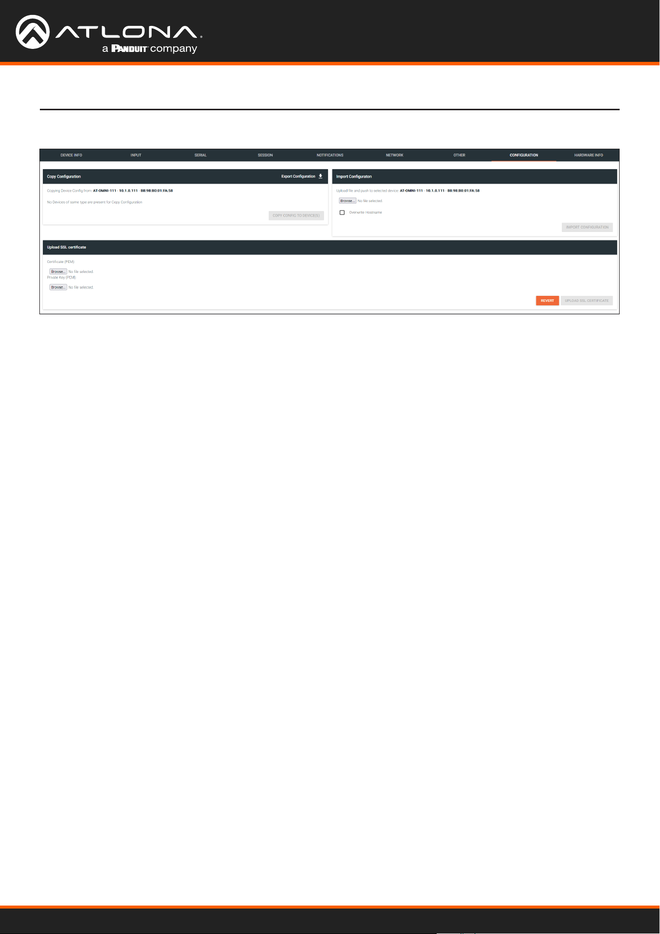
Using OmniStream
™
with Velocity
™
Device Manager
120
The Velocity Interface
CONFIGURATION page
Export Conguration
Click this button to export the current encoder system conguration to a .json le.
COPY CONFIG TO DEVICE(S)
Click this button to copy the current conguration to other OmniStream devices. OmniStream devices must be of the
same type to perform this operation.
Browse... (Certicate PEM)
Click these buttons to select the desired certicate.
Browse... (Private Key PEM)
Click these buttons to select the desired private key.
UPLOAD SSL CERTIFICATE
Click this button to upload the certicate/private key to the encoder.
REVERT
Click this button to restore the previous conguration.
Copy conguration
Upload SSL certicate
Browse...
Click this button to select the desired conguration le to be uploaded.
Overwrite Hostname
Click this box to overwrite the hostname of the destination device. Leaving this box unchecked will preserve the
destination hostname.
IMPORT CONFIGURATION
Click this button to upload the selected conguration le to the encoder.
Import Conguration

Using OmniStream
™
with Velocity
™
Device Manager
121
HARDWARE INFO page
Connection Status
Indicates the connection status of the device.
Alias
Displays the alias name.
Manufacturer
Displays the manufacturer name.
Model
Displays the model number.
IP Address
Displays the IP address of the unit.
Serial Number
Displays the serial number of the unit.
The Velocity Interface
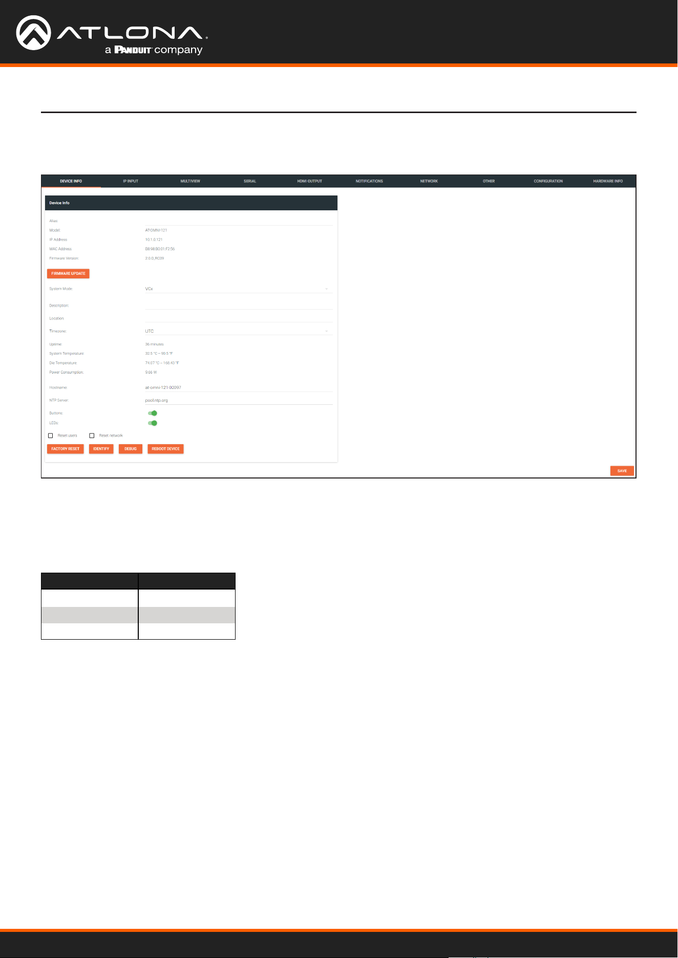
Using OmniStream
™
with Velocity
™
Device Manager
122
Decoders
Alias
Enter a name for the unit in this eld. This is optional.
Model
The model number of the unit.
Encoders Decoders
AT-OMNI-111 AT-OMNI-121
AT-OMNI-112 AT-OMNI-122
AT-OMNI-512 AT-OMNI-521
IP Address
Displays the IP address of the encoder.
MAC Address
Displays the MAC address of the encoder.
Firmware Version
The version of rmware that the OmniStream device is running. Always make sure the latest version of rmware is
installed.
FIRMWARE UPDATE
Click this button to update the rmware.
DEVICE INFO page
The Velocity Interface

Using OmniStream
™
with Velocity
™
Device Manager
123
Description
Provides the option of assigning descriptive name to the unit.
Location
Provides the option of assigning a description of where the unit is located.
Timezone
Displays the time zone format. Click the SET TIMEZONE button, to assign the time zone.
Date/Time
Displays the current date and time. Click the SET DATE/TIME button to set these values.
Uptime
Displays the elapsed time since the unit was powered-on or rebooted.
System Temperature
Displays the ambient enlosure temperature.
Die Temperature
Displays the value returned from the die temperature sensor (DTS) on the chip of the PCB.
Power Consumption
Displays the precise power consumption of the encoder.
Hostname
Displays the hostname of the encoder. By default, OmniStream encoders are assigned a default hostname, which is
constructed as follows: at-omni-[SKU]-[last ve digits of MAC address].
NTP Server
Displays the NTP server. This eld is set to pool.ntp.org by default. Click this eld to enter the desired NTP
server address.
Buttons
Click this toggle switch to enable or disable the button backlight indicators on the front-panel.
LEDs
Click this toggle switch to enable or disable all front-panel LED indicators and button backlight indicators.
The Velocity Interface
System Mode
Click this drop-down list to select the system mode. The default setting is VCx.
Mode Description
VCx This is the default mode and represents the latest codec technology from Atlona, with
outstanding support for computer graphics and motion video. VCx includes support for
4K60 4:4:4 fast switching, dual streaming from AT-OMNI-111 encoders, and multiview on
the decoders.
VC-2 Video Legacy OmniStream codec that provides the best viewing experience when streaming
motion graphics and/or video.
VC-2 PC application Legacy OmniStream codec that optimizes the image when viewing static images, such
as spreadsheets or similar content.

Using OmniStream
™
with Velocity
™
Device Manager
124
The Velocity Interface
Option Description
None Checked Resets the encoder with no factory-default settings.
Reset User Resets the encoder to factory-default settings and resets custom user information.
Reset Network Resets the encoder to factory-default settings and resets network information.
FACTORY RESET
Click this button to reset the encoder to factory-default settings. When performing a factory reset, the following
options can be selected, by clicking the check box. If no options are selected, then the encoder is reset with no
factory-default settings.
IDENTIFY
Click this button to physically identify a unit on the network. Clicking this button will cause all front-panel LED
indicators to ash for 10 seconds.
DEBUG
Click this button to instruct the unit to create a debug le. This le is used by Atlona Technical Support Engineers to
diagnose internal issues with the unit.
REBOOT DEVICE
Click this button to perform a soft reboot of the OmniStream device.
SAVE
Click this button to commit changes to the settings on this page.
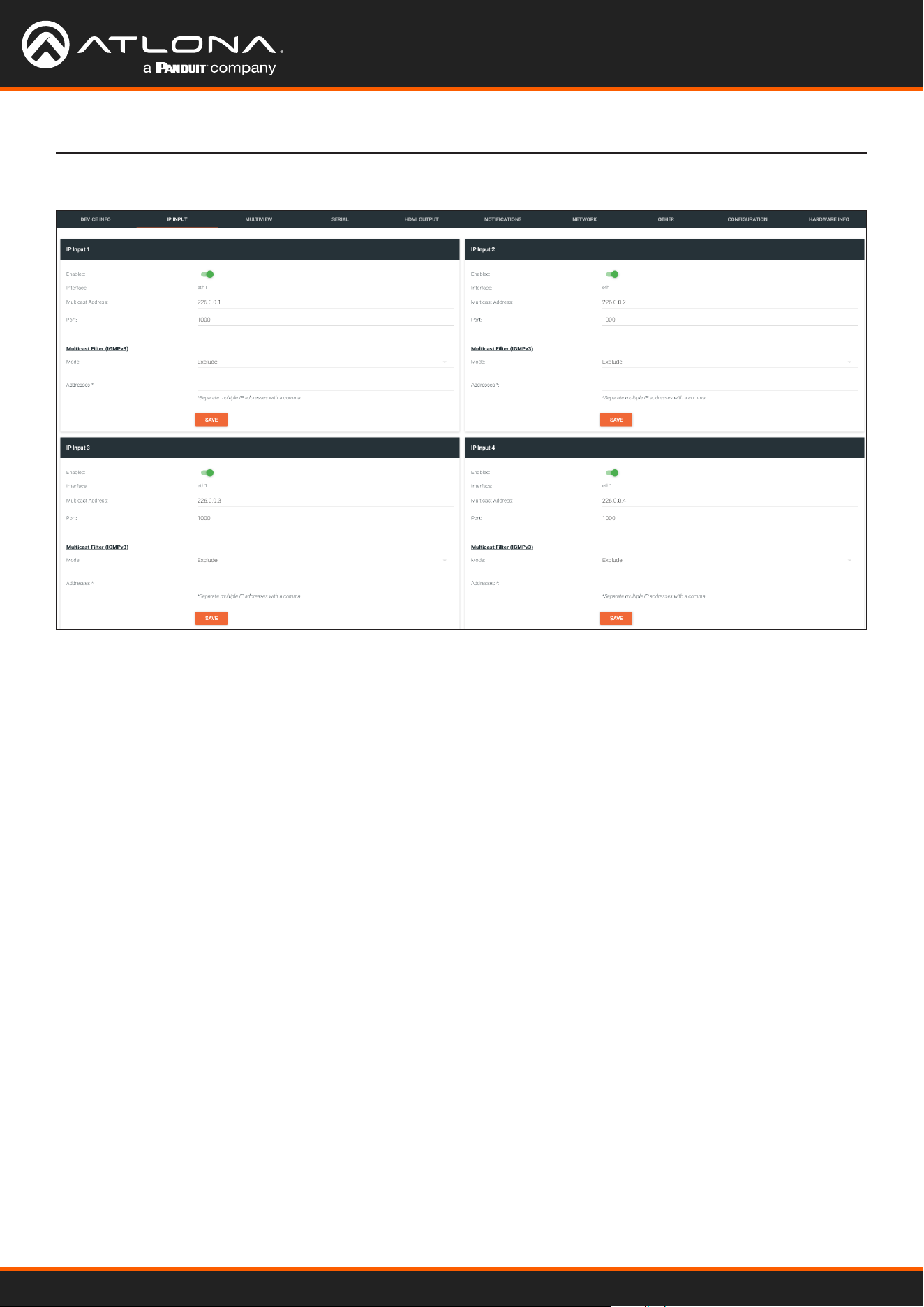
Using OmniStream
™
with Velocity
™
Device Manager
125
IP INPUT page
The Velocity Interface
Enabled
Click this toggle switch to enable or disable the IP input.
Interface
Click this drop-down list to select the desired Ethernet interface. This is only available on dual-channel decoders.
Multicast Address
Enter the multicast IP address of the subscribed encoder in this eld.
Port
Enter the port number of the subscribed encoder in this eld.
Multicast lter (IGMPv3) > Mode
Click this drop-down list to select the multicast ltering mode. Available options are exclude or include.
Multicast lter (IGMPv3) > Addresses
Enter the desired address(es) in this eld. Separate multiple multicast IP addresses with a comma delimiter.
SAVE
Click this button to commit all changes in the Input window group.
The following elds apply to all IP Input window groups.
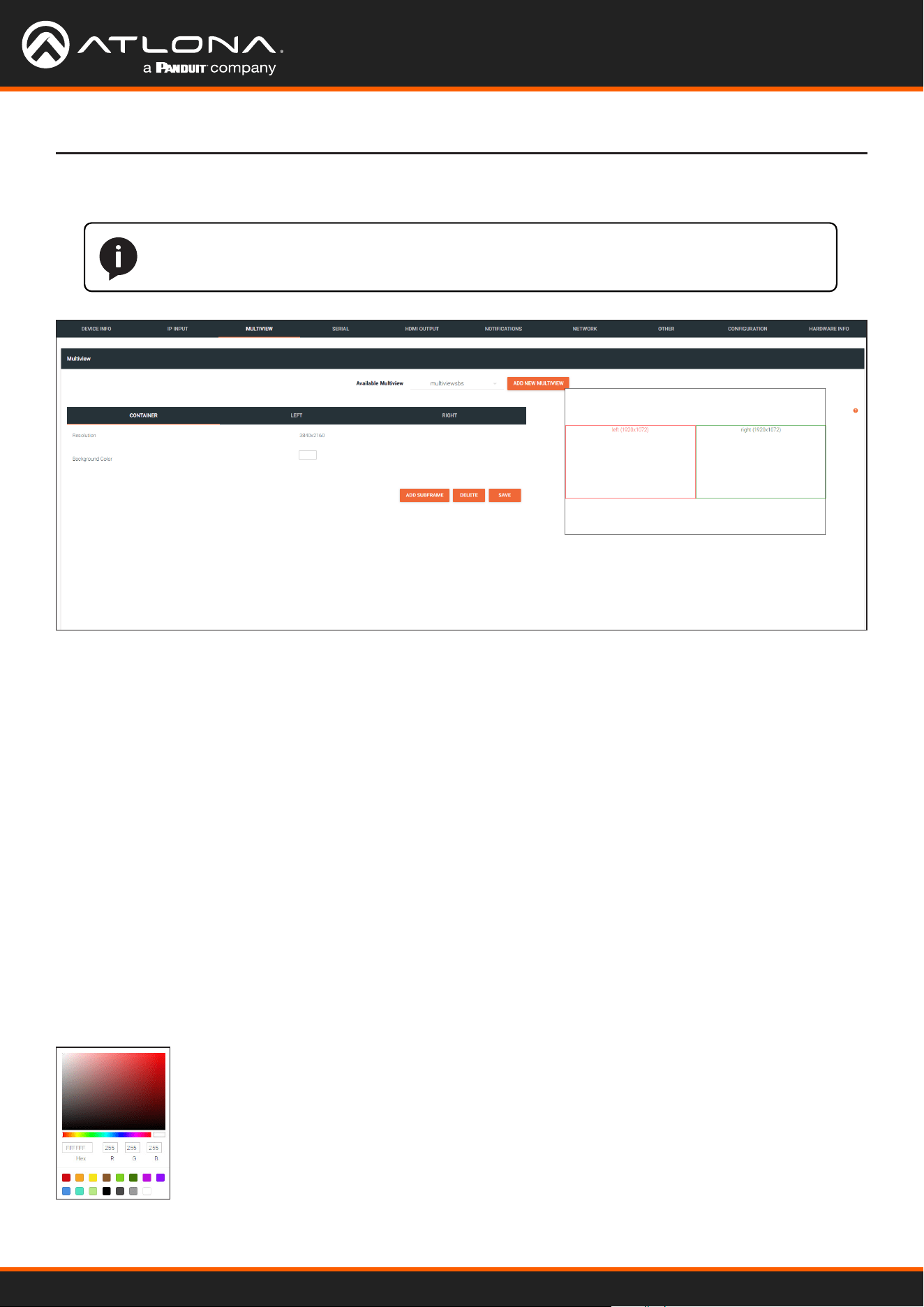
Using OmniStream
™
with Velocity
™
Device Manager
126
MULTIVIEW page
The Velocity Interface
NOTE: This page is only availble if the System Mode is set to VCx. Refer to the DEVICE INFO
page (page 122) for more information.
Available Multiview
When a multiview is created, the name of the multiview will be displayed here. If more than one multiview
conguration exists, then click this drop-down list to select the desired multiview.
ADD NEW MULTIVIEW
If a multiview has not been congured, this will be the only button displayed on this page. Click this button to create
a multiview. For details on conguring a multiview refer to Multiview and Dual-Streaming Tutorial (page 48) for
more information.
Resolution
Displays the output resolution of the multiview.
Background Color
The background color is set using RGB values between 0 and 255. The default setting is black (0,0,0). Click this box
to display the color swatch and to change the background color.
Multiview window group
CONTAINER window group

Using OmniStream
™
with Velocity
™
Device Manager
127
Subframe window groups
The Velocity Interface
The name of these window groups will change, based on the multiview layout that is selected. However, the
information contained within the window group will be the same.
Name
The name of the subframe and the resolution of the subframe. This eld cannot be modied.
Input
Click this drop-down list to select the desired IP input.
X
Enter the x-position of the anchor point in this eld.
Y
Enter the y-position of the anchor point in this eld.
Anchor
Click this drop-down list to select the anchor point for the subframe. Anchor points are: top left, top right,
bottom left, bottom right, and center.
Z-order
Enter the z-order value in this eld. Subframes with a higher z-order value will be moved to the front (on top of)
subframes with lower z-order values.
Input Status
Displays the status and resolution of the input, if it is active. If it is not active, then No Video will be displayed.
Output Status
Displays the status and resolution of the output, if it is active. If it is not active, then No Video will be displayed.
DELETE
Deletes the subframe from the multiview window group.
SAVE
Click this button commit changes to the subframe window group.
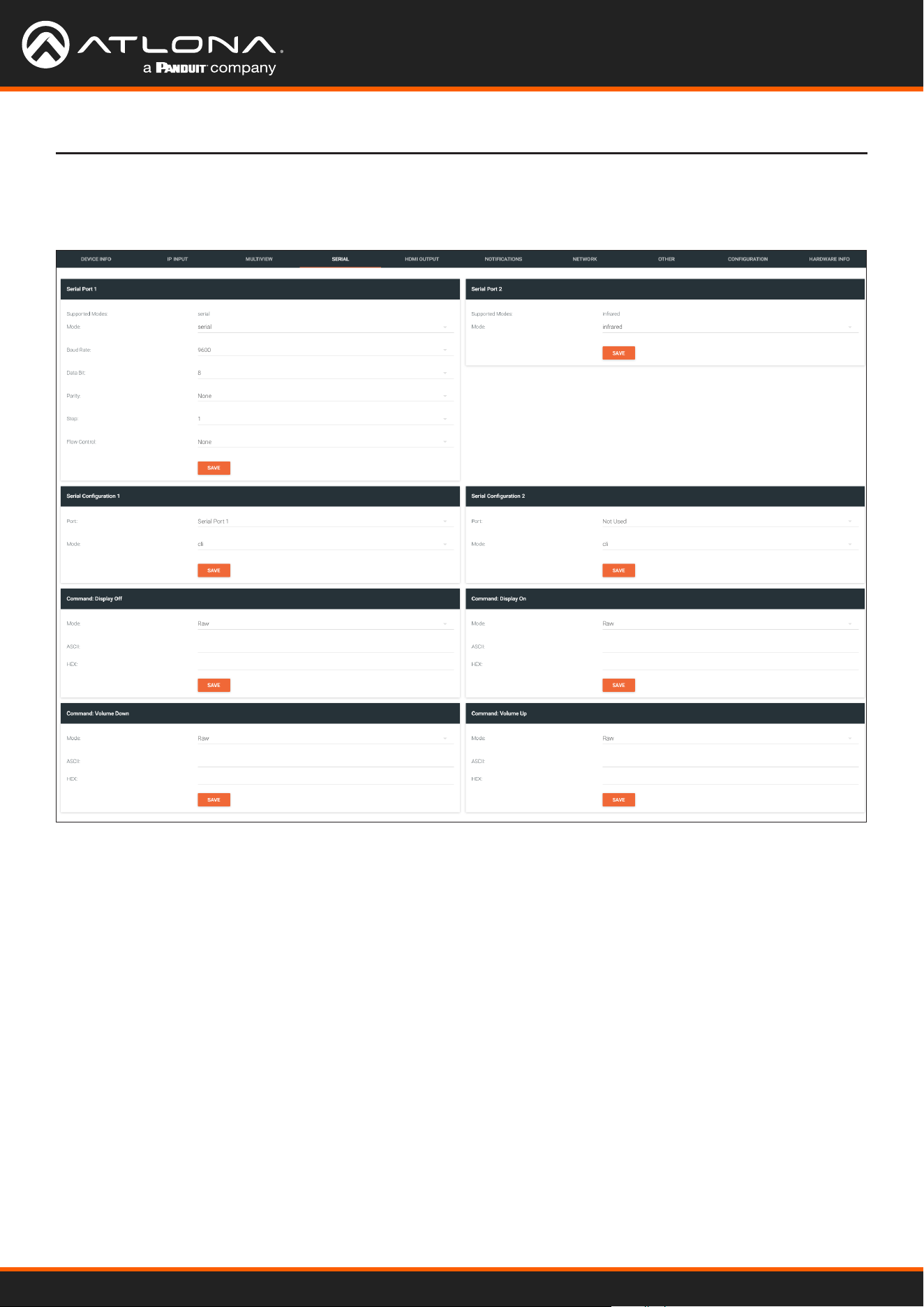
Using OmniStream
™
with Velocity
™
Device Manager
128
The Velocity Interface
The Serial page provides serial port conguration when using control signals.
Supported Modes
Lists the supported protocols for the serial port.
Mode
Click this drop-down list to select the desired serial mode. Available values will be reected in the Supported
Modes eld.
Baud Rate
Click this drop-down list to select the desired baud rate: 115200, 57600, 38400, 19200, or 9600.
Data Bit
Click this drop-down list to select the number of data bits: 6, 7, or 8.
Parity
Click this drop-down list to select the parity bit: None, Odd, Even, Mark, or Space.
SERIAL page
Serial Port window groups
The following elds apply to both Serial Port window groups.

Using OmniStream
™
with Velocity
™
Device Manager
129
The Velocity Interface
Stop
Click this drop-down list to select the stop bit: 1, 1.5, or 2.
SAVE
Click this button to save all changes under the Serial Port window group.
Serial Conguration window groups
The following elds apply to both Serial conguration window groups. The single-channel encoder will only have
one Serial conguration window group.
Port
Click this drop-down list to select the desired serial port.
Mode
Click this drop-down list to select the desired control mode. Available values are: cli and tcpproxy. Select
tcpproxy to send IP commands directly to the decoder, which are then output over RS-232 to the display (sink)
device. Selecting the cli option will pass through RS-232 data, directly from a control system, to the sink device
that is connected to the decoder.
SAVE
Click this button to commit all changes within the Serial conguration window group.
Command window groups
By default, window groups for the following commands are created: Display O, Display On, Volume Down,
and Volume Up.
Interpret on
Click this drop-down list to select the endpoint where the command will be processed: encoder or decoder.
ASCII
Enter the ASCII representation of the command string in this eld.
HEX
Enter the hexadecimal representation of the command in this eld.
NOTE: When entering the command string, it is not required to enter the string under both the
ASCII and HEX fields. The encoder requires that one field be completed.
SAVE
Click this button to commit all changes within the Command window group.
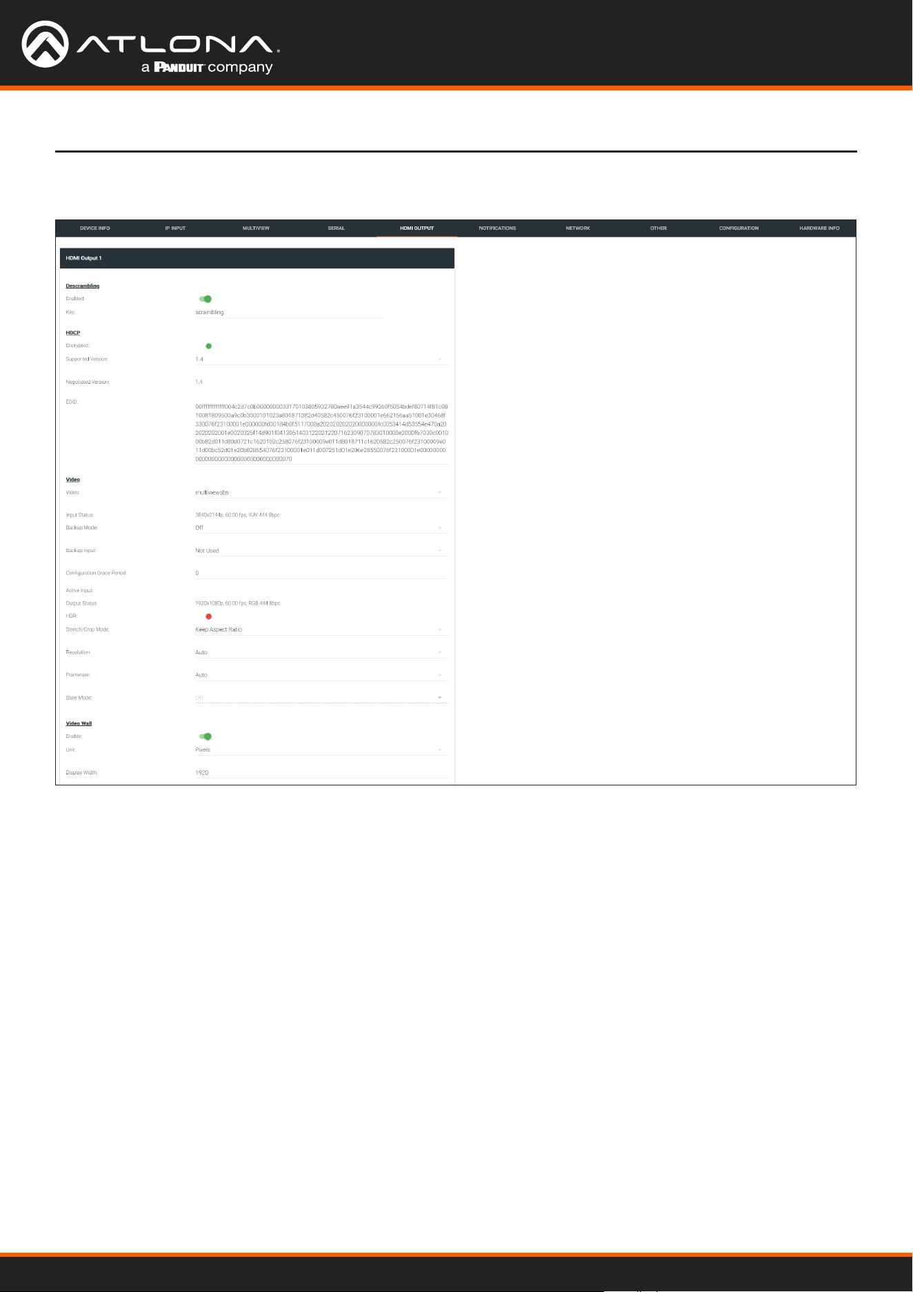
Using OmniStream
™
with Velocity
™
Device Manager
130
HDMI OUTPUT page
Descrambling
HDCP
The Velocity Interface
Enabled
Click this toggle switch to enable or disable scrambling. If a scrambling key is used on the subscribed encoder, then
descrambling must be enabled on the decoder in order for the source signal to reach the sink device.
Key
Enter the descrambling key in this eld. This key must match the scrambling key on the subscribed encoder.
Encrypted
This indicator will be green if the stream content is HDCP-encrypted.
Supported Version
Click this drop-down list to select the supported version of HDCP.
Negotiated Version
Displays the version of HDCP used by the stream.
EDID
This eld will display the EDID of the connected display. This raw data can be copied and stored under the EDID
page, if desired.

Using OmniStream
™
with Velocity
™
Device Manager
131
The Velocity Interface
Video
Video
Click this drop-down list to select the desired IP input. Available options are ip_input1 - ip_input12, none,
generator, and multiview (if congured).
Input Status
Displays the input status. If no video stream is detected, then “No active video” will be displayed.
Backup Mode
Click this drop-down list to select the backup mode. Both Video and Audio provide the Backup Mode feature.
Mode Description
Off
Backup source is disabled; join request not sent.
Join Active
The decoder sends a join request only when the decoder decides to switch between video
sources. Switch time will not exceed 5 seconds.
Join Always
The decoder always joins to the backup video source. Switch time will not exceed 0.5 seconds.
Backup Input
Select the secondary video backup IP input from this drop-down list. If the primary IP input is down, then the
decoder will automatically switch to this input. Refer to the Backup Mode option, above, for setting the conditions
for switching inputs. Both Video and Audio provide the Backup Input feature.
Conguration Grace Period
To prevent the decoder from automatically making the redundancy switch, when redundancy is enabled, a grace
period can be entered. By default, the grace period is set to zero seconds. If set to zero seconds, automatic failover
will occur, if the stream is interrupted for any reason. Refer to Conguring Redundant Streams (page 74) for more
information.
Active Input
Displays the active video input.
Output Status
Displays the active video input. If no input is active or detected, then this eld will display “No active video”.
HDR
This indicator will be green if HDR video is present.
Stretch / Crop Mode
Click this drop-down list to select the aspect ratio.
Mode Description
Keep Aspect Ratio
Aspect ratio is preserved; the output on the decoder will be the same as the input on the
encoder.
Full Screen
Stretches the image to fill the screen. In some cases this can distort (“stretch”) the
image.
16:9
Sets the aspect ratio to 16:9 “widescreen” format, usually associated with HDTV formats.
16:10
Sets the aspect ratio to 16:10 “widescreen” format, usually associated with computer
displays and smart devices.
4:3
Sets the aspect ratio to 4:3 “pan-and-scan” format, usually associated with SDTV.

Using OmniStream
™
with Velocity
™
Device Manager
132
The Velocity Interface
Resolution
Click this drop-down list to select the desired output resolution. This is a scaler feature which can either upscale
or downscale the output on the decoder. If Input is selected, then no scaling will be applied to the output. Select
Auto to use the EDID of the sink device to determine the output resolution.
Resolutions
Input 1440x1050
Auto 1440x900
4096x2160 1280x1024
3840x2160 1280x800
1920x1200 1280x768
1920x1080 1280x720
1680x1050 1024x768
1600x900
Framerate
Sets the output frame rate. Available options are auto, 60 Hz, 50 Hz, and 30 Hz, except for the OMNI-122 where
the options are auto and 30 Hz.
Slate Mode
Click this drop-down list to select the slate mode. Refer to Slate / Logo Insertion (page 83) for more information.
NOTE: When working with VESA resolutions 1360x768p60 and 1366x768p60, the Resolution
drop-down list must be set to Auto.
Mode Description
Off
Disables the image from being displayed.
Manual
Stretches the image to fill the screen. In some cases this can distort (“stretch”) the image.
Auto
The image will only be displayed when the source signal is lost. For example, this mode is
useful in conference room applications for displaying system instructions when no sources are
connected.
Enable
Click this toggle switch to enable or disable the video wall option. Refer to Creating Video Walls (page 58) for
more information on using video walls.
Unit
Click this drop-down list to specify the units. Available options are pixels, mm, and inches.
Display Width
Species the width of the video wall.
Display Height
Species the height of the video wall.
Horizontal
The number of video wall rows.
Vertical
The number of video wall columns.
Video Wall

Using OmniStream
™
with Velocity
™
Device Manager
133
The Velocity Interface
Rotation
Adjusts the rotation angle of the image. Available options are 0, 90, 180, and 270.
Edge Compensation
Adjusts edge compensation. Available options are none, bezel compensation, and edge blending.
Fast Switching Enable
Click this toggle switch to enable or disable fast-switching. When enabled, the fast-switching timeout interval can
also be adjusted. Refer to Fast Switching (page 81) for more information.
Fast Switching Timeout (s)
Sets the timeout interval for fast switching. Only available if fast switching is enabled.
TO PRIMARY
Click this button to assign as the Primary IP Input. Both Video and Audio support this feature.
TO BACKUP
Click this button to force the audio stream to fall over to the Backup IP Input (if redundancy is congured).
Both Video and Audio support this feature.
Audio
Input
Click this drop-down list to select the primary audio IP input. Select the Not Used option to leave the audio input
unassigned.
Backup Mode
Click this drop-down list to select the backup mode. Both Video and Audio provide the Backup Mode feature.
Mode Description
Off Backup source is disabled; join request not sent.
Join Active The decoder sends a join request only when the decoder decides to switch between audio
sources. Switch time will not exceed 5 seconds.
Join Always The decoder always joins to the backup audio source. Switch time will not exceed 0.5 seconds.
Backup Input
Select the secondary video backup IP input from this drop-down list. If the primary IP input is down, then the
decoder will automatically switch to this input. Refer to the Backup Mode option, above, for setting the conditions
for switching inputs. Both Video and Audio provide the Backup Input feature.
Conguration Grace Period
To prevent the decoder from automatically making the redundancy switch, when redundancy is enabled, a grace
period can be entered. By default, the grace period is set to zero seconds. If set to zero seconds, automatic failover
will occur, if the stream is interrupted for any reason. Refer to Conguring Redundant Streams (page 74) for more
information.
Active Input
Displays the active audio input.
Downmixing
Click this drop-down list to select how LPCM audio will be down-mixed. Note that lossless audio formats cannot be
down-mixed.

Using OmniStream
™
with Velocity
™
Device Manager
134
The Velocity Interface
Enable AES67
Click this toggle switch to enable or disable AES67. When enabled, the toggle switch will be orange. Refer to AES67
Audio (page 75) for more information.
Status
Displays the active audio input. If no input is active or detected, then this eld will display “No active audio”.
Mute
Click this toggle switch to enable or disable the audio output. If enabled, the toggle switch will be green.
Volume
Click the speaker icon on the left to decrease volume. Click the speaker icon on the right to increase volume.
Range: 0 to 15.
Analog Power Status
This indicator will be green when the decoder is powered by the optional external 48 V DC power supply.
Analog Power
If analog output is connected to the decoder, then click this toggle switch to use the analog audio output. When
enabled, this toggle switch will be orange.
TO PRIMARY
Click this button to assign as the Primary IP Input. Both Video and Audio support this feature.
TO BACKUP
Click this button to force the audio stream to fall over to the Backup IP Input (if redundancy is congured).
Both Video and Audio support this feature.
AUX (CEC)
Click this drop-down list to select the desired IP input for CEC control. Available options are ip_input1 - ip_
input12, none, and generator.
Auto On
Click this toggle switch to enable or disable power-on. When enabled this toggle switch will be green and the power-
on command will be sent to the display when an A/V signal is detected.
Projector Cooldown (s)
Enter the time interval, in seconds, before the projector can be powered-o. This time interval prevents the decoder
from sending additional commands until the projector has had time to complete its cool-down process.
Standby Timeout
Enter the time interval, in seconds, before the next command can be accepted by the display.
Type
Click this drop-down list to select the display mode.
Type Description
DispSW AVon Display switches on/o, source audio/video signal always on.
DispSW AVSW Display switches on/o, source audio/video signal switches on/o.
AV SW Display is always on, source audio/video signal switches on/o
Always on Display is always on, source audio/video signal always on.
SAVE
Click this button to commit all changes within the HDMI Output window group.
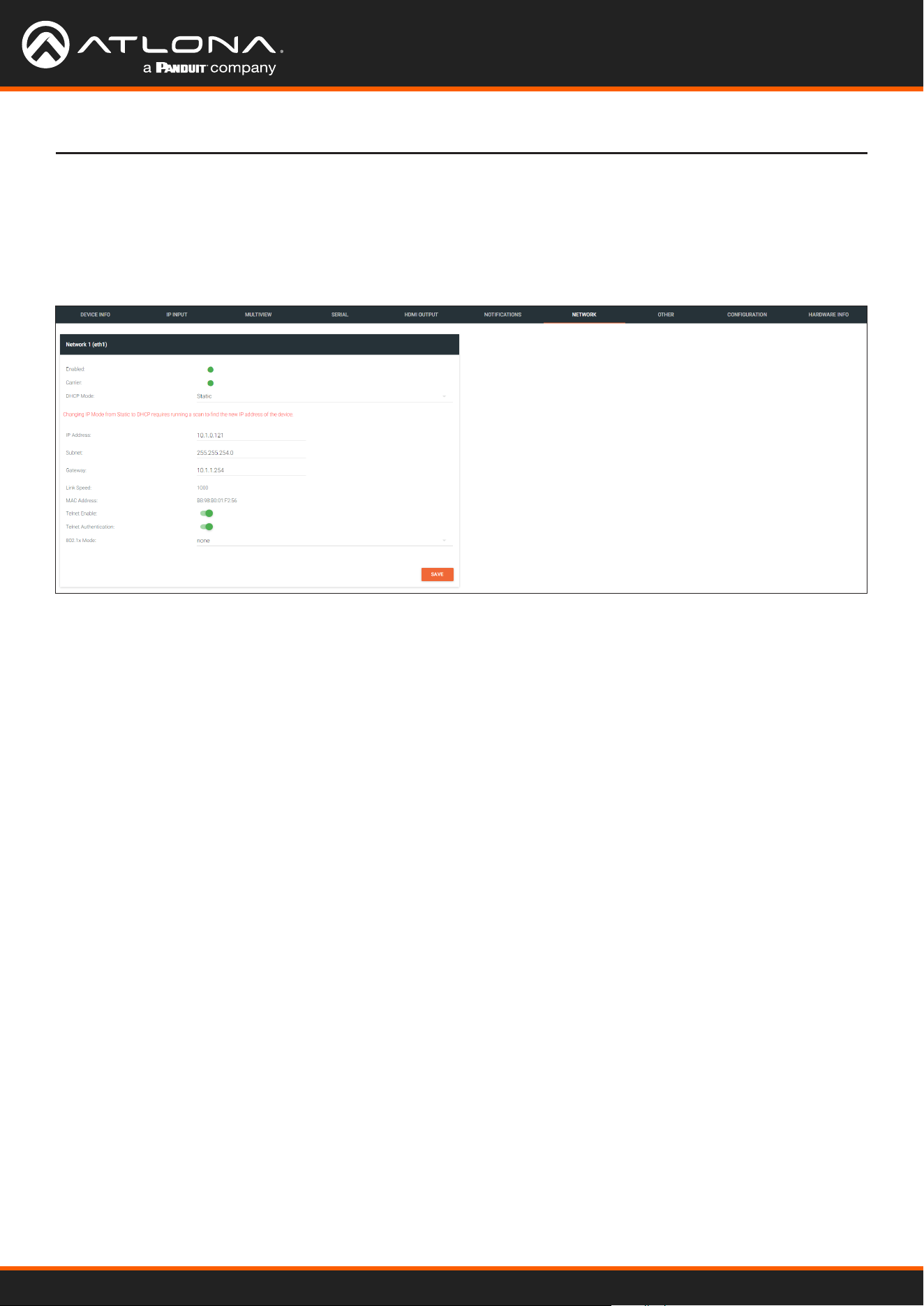
Using OmniStream
™
with Velocity
™
Device Manager
135
The Velocity Interface
The NETWORK page provides the ability to enable or disable DHCP mode for each video channel. When DHCP
mode is disabled, the IP address, subnet mask, and gateway must be provided. If using the dual-channel version,
then the information on both Channel 1 and Channel 2 are provided. This screen is identical to the NETWORK page
for the encoder.
NETWORK page
Enabled
This indicator displays whether or not the video stream for this channel is active. If the indicator is green, then the
video stream is active.
Carrier
If this indicator is green, then an active link exists. Otherwise, if no link exists, this indicator will be red.
DHCP Mode
Click this drop-down list to select the desired IP mode. Select DHCP to let the DHCP server (if present) assign the
encoder the IP settings; Subnet and Gateway elds will automatically be populated. When static is selected, the
information for the IP Address, Subnet, and Gateway elds must be entered.
IP Address
Displays the IP address used by the channel. This eld can only be changed if Mode is set to static.
Subnet
Displays the subnet mask for the channel. This eld can only be changed if Mode is set to static.
Gateway
Displays the gateway (router) address for the channel. This eld can only be changed if Mode is set to static.
Link speed
Displays the Ethernet interface link speed in Mbps. This eld cannot be modied.
MAC address
Displays the MAC address of the Ethernet interface.

Using OmniStream
™
with Velocity
™
Device Manager
136
The Velocity Interface
Telnet Enable
Click this toggle switch to enable or disable Telnet. If disabled, then Telnet sessions to the encoder cannot be
established.
Telnet Authentication
Click this toggle switch to enable or disable Telnet authentication. If enabled, then the toggle switch will be orange.
Once enabled, connecting to the encoder using Telnet will require login credentials. The default credentials are:
Username: admin
Password: Atlona
802.1x Mode
Click this drop-down list to select the desired authentication mode.
Protocol Description
none 802.1X protocol disabled
PEAP/MSCHAPv2 Protected EAP; requires basic credentials in addition to a CA (certicate authority)
certicate.
EAP-TLS EAP Transport Layer Security; requires a client certicate, client private key, and CA
(certicate authority) certicate.
SAVE
Click this button to commit all changes within the Network window group.
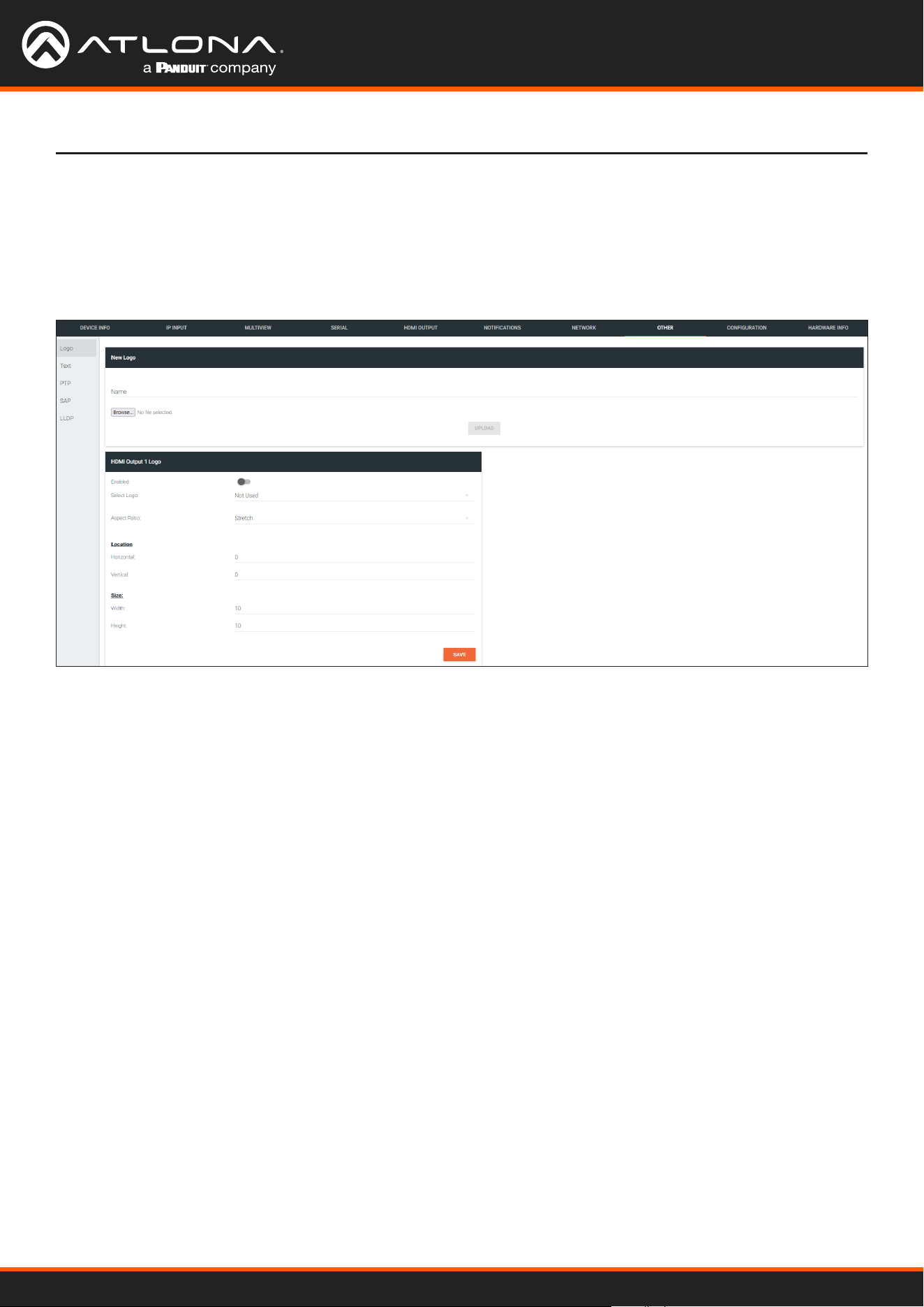
Using OmniStream
™
with Velocity
™
Device Manager
137
The Velocity Interface
The Other page provides logo/slate, text, and PTP management. Click the menu in the upper-left corner of the
Velocity screen to switch between Logo, Text, PTP, SAP, and LLDP screens.
The Logo page provides the ability to upload a custom logo and is similar to the LOGO page on the encoder. Refer
to Slate / Logo Insertion (page 83) for more information on these settings.
OTHER > LOGO page
New Logo window group
HDMI Output Logo window group
Name
Enter a name for the logo in this eld.
Browse...
Click this button to select the logo le to be uploaded. Files must be in .png format and must not exceed 5 MB
(5120000 bytes) in size. When an image le is uploaded, it will appear in the Logo drop-down list.
UPLOAD
Click this button to upload the logo le to the encoder.
Enabled
Click the toggle switch to enable or disable the logo. If the toggle switch is green, then the logo will be enabled.
Logo
Click this drop-down list to select the desired logo. To disable the use of a logo, set to Not Used.
Aspect Ratio
Click this drop-down list to select the type of aspect ratio to be applied to the logo.

Using OmniStream
™
with Velocity
™
Device Manager
138
The Velocity Interface
Horizontal
Enter the horizontal position of the logo on the screen. This value is based on the total horizontal resolution of the
screen.
Vertical
Enter the vertical position of the logo on the screen. This value is based on the total vertical resolution of the screen.
Width
Enter the width of the logo. This value is based on the total horizontal resolution of the screen.
Height
Enter the height of the logo. This value is based on the total vertical resolution of the screen.
SAVE
Click this button to commit all changes within the HDMI Input window group.

Using OmniStream
™
with Velocity
™
Device Manager
139
The Velocity Interface
OTHER > TEXT page
HDMI Output Text window group
Enabled
Click this toggle switch to enable or disable the text. When the toggle switch is orange, the text will be enabled.
Text
Enter the desired text in this eld.
Scroll Speed
Enter the scrolling speed in this eld. Integer values from -255 to 255 are valid. Negative numbers will scroll the
text from left to right. Positive numbers will scroll text from right to left.
Iterations
Enter the number of iterations in the Iteration eld. Set this eld to 0 (zero) to set the number of iterations to innity.
Color
Click this drop-down list to select a solid color preset: red, green, black, white, yellow, or blue.
Red, Green, Blue, Alpha
Click these elds to ne tune the color of the text. Integer values from 0 to 255 are valid for all elds. Adjust the
Alpha eld to control the transparency of the text. An alpha value of 255 is opaque and a value of 0 is transparent.
Horizontal
Enter the horizontal position of the text in this eld.
Vertical
Enter the vertical position of the text in this eld.
Width
Enter the width of the text in this eld. This value is
based on the horizontal resolution of the screen.
Height
Enter the height of the text in this eld. This value is
based on the vertical resolution of the screen.
SAVE
Click this button to commit all changes within the HDMI
Input Text window group.
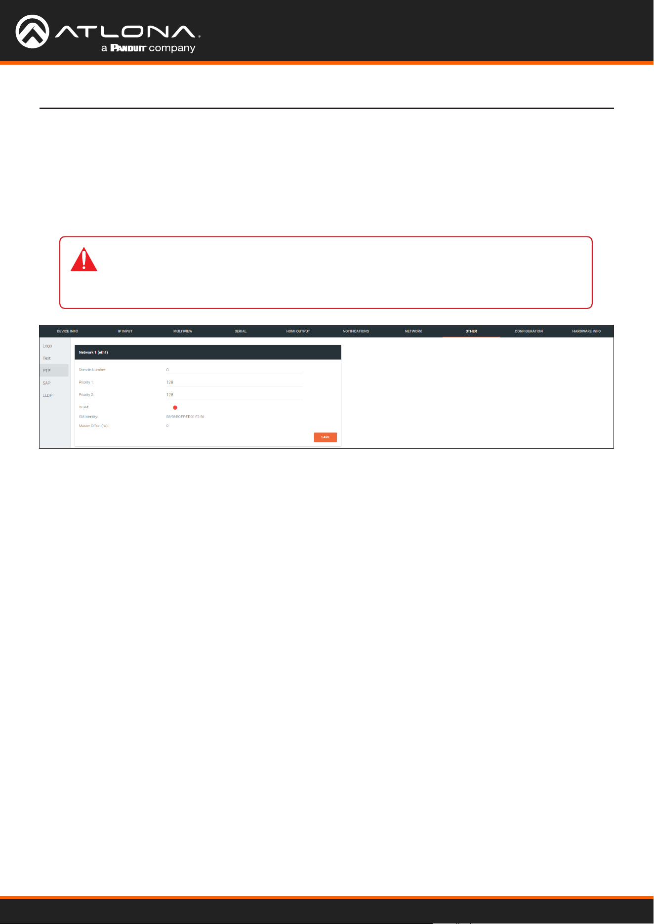
Using OmniStream
™
with Velocity
™
Device Manager
140
The Velocity Interface
OTHER > PTP page
Network window group
The PTP page provides options for adjust Precision Time Protocol (PTP) for AES67 audio streams. PTP is used by
AES67 to keep all audio streams synchronized.
For a system utilizing PTP, all devices undergo an automatic self-election process to choose the interface to be used
as the PTP grandmaster (GM) clock, based on the accuracy of the device’s clock and the device’s congured priority.
A lower priority number means the unit is more likely to get selected as the GM.
IMPORTANT: If a new device is added to the network and the GM changes, a brief outage will
be experienced while all connected devices synchronize with the new clock. Because of this,
Atlona recommends that one unit gets manually dened as the GM and have both Priority 1
and Priority 2 elds be set to 1.
Domain Number
Enter the domain number in this eld. Valid entries are 0 through 127.
Priority 1
Enter the priority number in this eld.
Priority 2
Enter the priority number in this eld.
Is GM
This indicator displays the existence of a grandmaster clock for the specied PTP domain number. If the indicator is
green, then the grandmaster clock exists on this interface.
GM Identity
The grandmaster clock identity. If this eld is blank, then it means that this interface is the grandmaster clock.
Master Oset
Displays the grandmaster clock oset.
SAVE
Click this button to commit all changes the Network window group.
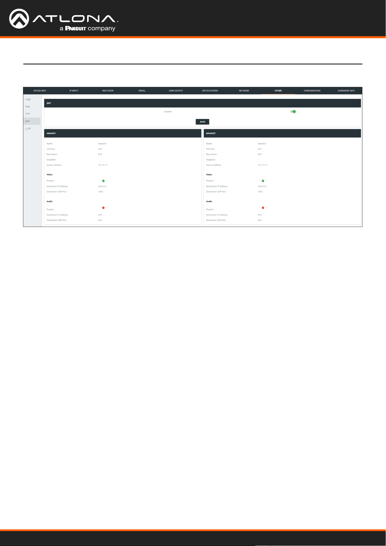
Using OmniStream
™
with Velocity
™
Device Manager
141
The Velocity Interface
OTHER > SAP page
SAP window group
session window groups
Enable
Click this toggle to enable or disable SAP. This feature is enabled when the toggle switch is green. This is the default
setting.
If SAP is enabled, seesion windows will appear on this page and display information about each session.
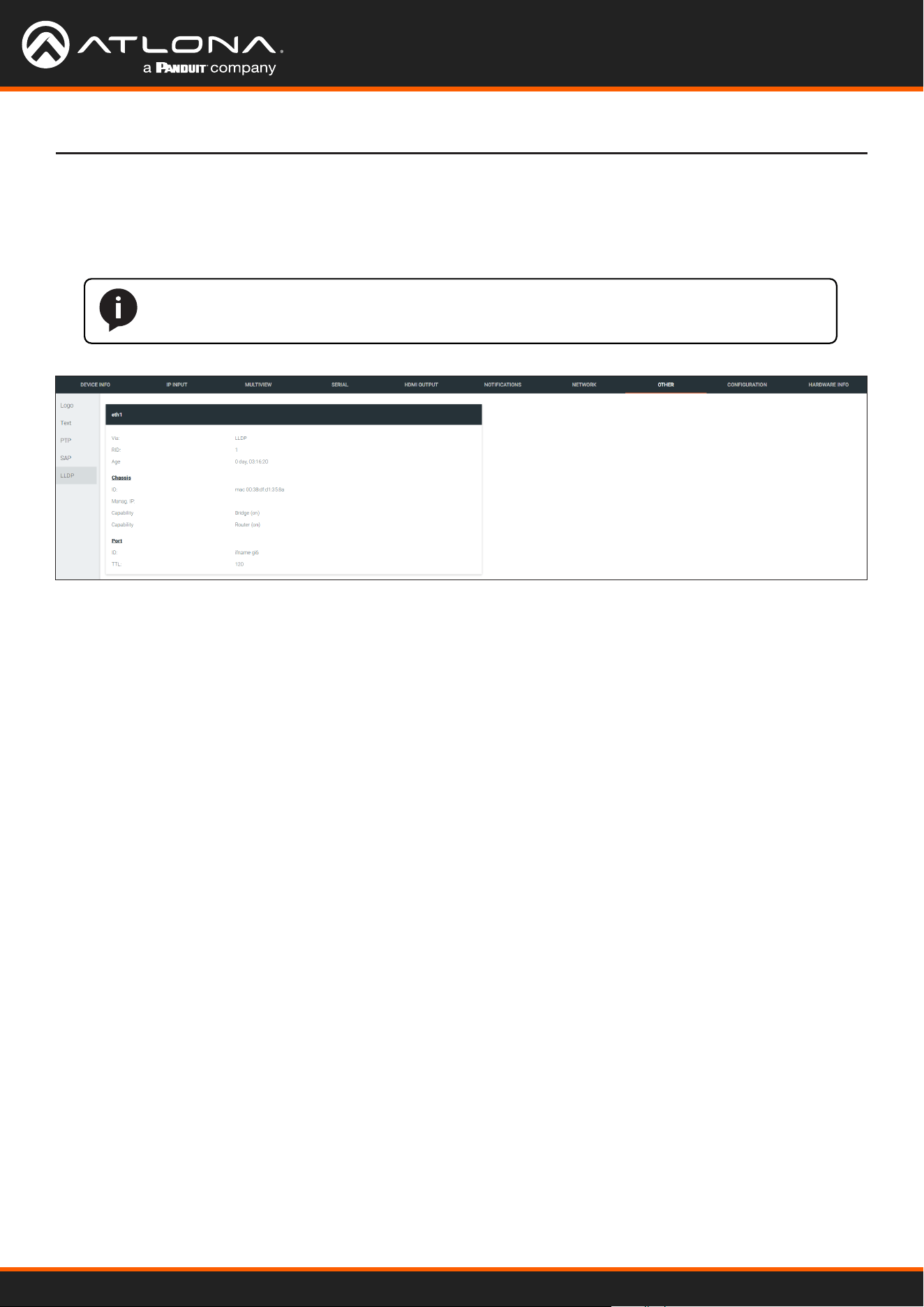
Using OmniStream
™
with Velocity
™
Device Manager
142
The Velocity Interface
OTHER > LLDP page
eth window group
The Link Layer Discovery Protocol (LLDP) page returns information about the switch that the encoder is connected
to. If both interfaces from a dual-channel encoder are connected to the switch, then two eth window groups will be
displayed.
NOTE: LLDP must be enabled on the switch that the encoders are connected to, in order for
the switch information to be displayed.
Via
The discovery protocol being used.
RID
The router ID.
Age
Up-time of the interface.
Chassis ID
The MAC address of the interface.
Chassis Capability
Indicates the device function, such as bridge (switch), router, etc.
Port ID
The port ID.
TTL
The Time-To-Live value.

Using OmniStream
™
with Velocity
™
Device Manager
143
The Velocity Interface
CONFIGURATION page
Export Conguration
Click this button to export the current decoder system conguration to a .json le.
COPY CONFIG TO DEVICE(S)
Click this button to copy the current conguration to other OmniStream devices. OmniStream devices must be of the
same type to perform this operation.
Browse... (Certicate PEM)
Click these buttons to select the desired certicate.
Browse... (Private Key PEM)
Click these buttons to select the desired private key.
UPLOAD SSL CERTIFICATE
Click this button to upload the certicate/private key to the encoder.
REVERT
Click this button to restore the previous conguration.
Copy conguration
Upload SSL certicate
Browse...
Click this button to select the desired conguration le to be uploaded.
Overwrite Hostname
Click this box to overwrite the hostname of the destination device. Leaving this box unchecked will preserve the
destination hostname.
IMPORT CONFIGURATION
Click this button to upload the selected conguration le to the decoder.
Import Conguration

Using OmniStream
™
with Velocity
™
Device Manager
144
The Velocity Interface
HARDWARE INFO page
Connection Status
Indicates the connection status of the device.
Alias
Displays the alias name.
Manufacturer
Displays the manufacturer name.
Model
Displays the model number.
IP Address
Displays the IP address of the unit.
Serial Number
Displays the serial number of the unit.
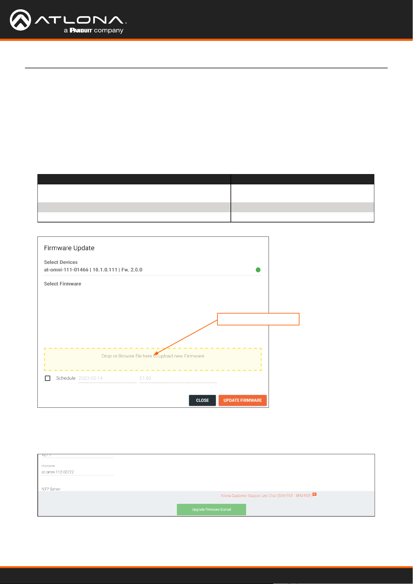
Using OmniStream
™
with Velocity
™
Device Manager
145
Appendix
Updating the Firmware
1. Select the desired encoder/decoder within the Velocity Device Manager.
2. Click DEVICE INFO in the menu bar.
3. Click the UPDATE FIRMWARE button to display the Firmware Update dialog.
3. Click and drag the rmware le to the yellow box, shown below. ,OmniStream rmware les use the .v2pup le
extension.
Firmware le OmniStream SKU
at-omni-single-upgrd-os-[version].vpup2
AT-OMNI-111, AT-OMNI-121,
AT-OMNI-111-WP
at-omni-dual-upgrd-os-[version].vpup2
AT-OMNI-112, AT-OMNI-122
at-omni-residential-upgrd-os-[version].vpup2
AT-OMNI-512, AT-OMNI-521
Drag firmware file here
4. Click the UPDATE FIRMWARE button to begin the update process.
5. The Upgrade Firmware Started message box will be displayed.

Using OmniStream
™
with Velocity
™
Device Manager
146
Appendix
6. Click the orange up-arrow icon, in the upper-right corner of the screen, as shown below. If this icon is orange,
it indicates that a rmware update is in progress. The progress bar for the update process will be displayed.
The update process should take a few seconds.
7. Click the “X” to close out the progress bar window, then click the CLOSE button to dismiss the Firmware
Update message box.
8. The rmware update process is complete.
9. Clear the web browser cache and refresh the web page. The new rmware version will appear in the Firmware
Version eld, under the DEVICE INFO page.
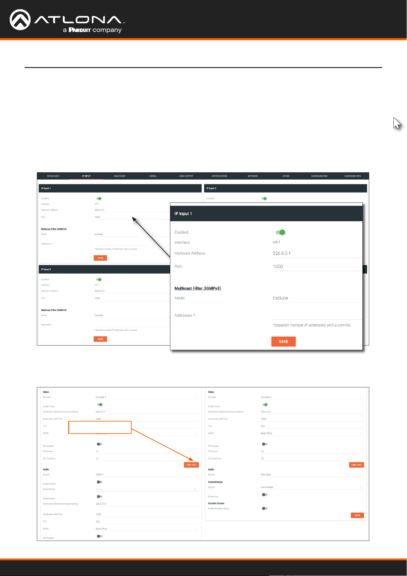
Using OmniStream
™
with Velocity
™
Device Manager
147
Performing a Link Test
Follow the procedure below to perform a link integrity test between an encoder and decoder(s).
1. Go to the encoder.
2. Verify that all desired decoders are subscribed to the encoder’s multicast address and port number. In the
decoder example below, the IP INPUT > IP Input 1 > Multicast Address eld is set to 226.0.0.1. This is the
same IP address that is assigned to the SESSION > Stream 1 > Destination Multicast/Unicast Address eld
on the encoder.
3. On the encoder, click SESSION in the menu bar.
4. Under the Video section, click the LINK TEST button.
LINK TEST button
Appendix
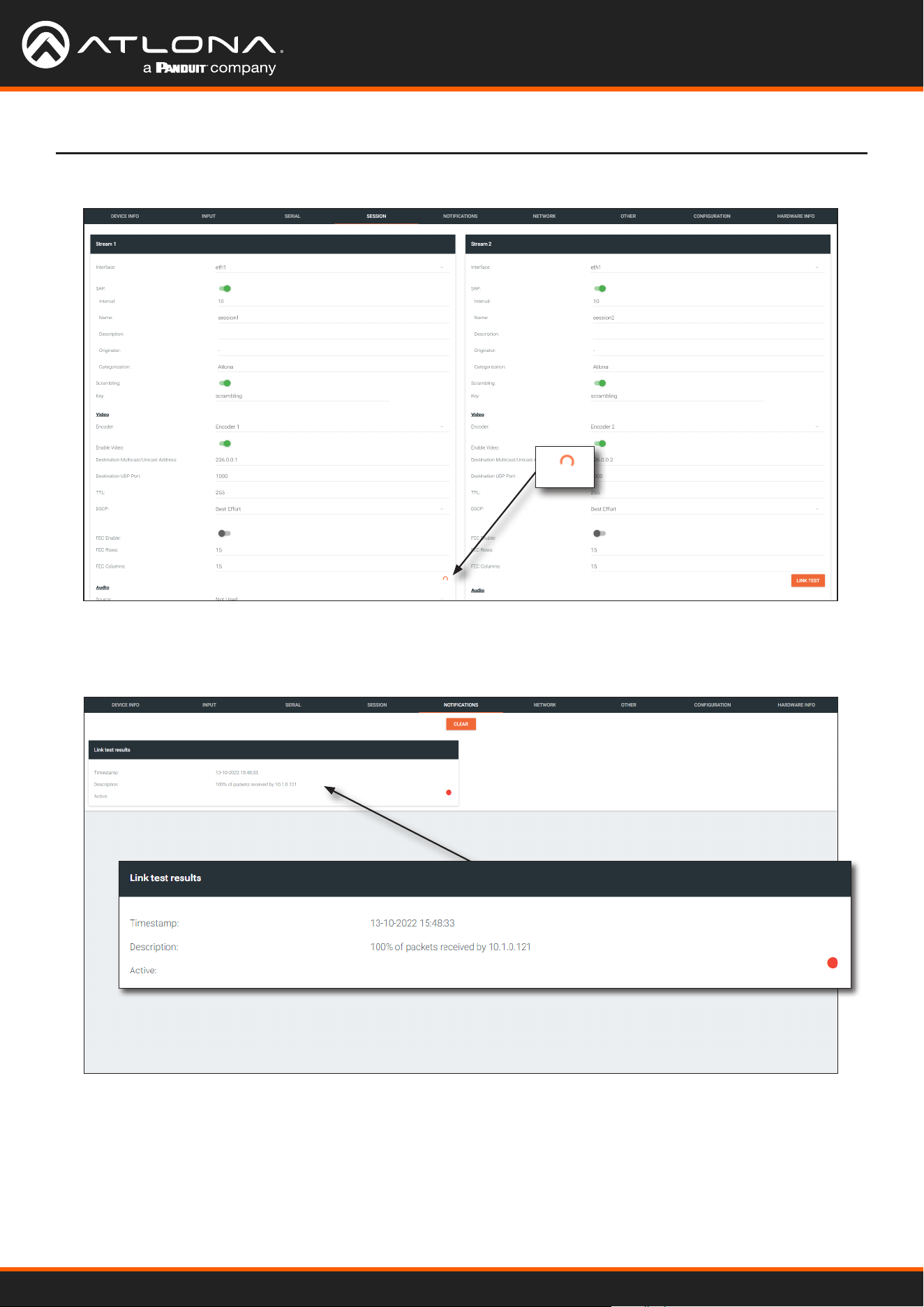
Using OmniStream
™
with Velocity
™
Device Manager
148
5. The LINK TEST button will be hidden and an animated icon will appear, indicating that the link test is in progress.
6. After the link test has completed, the LINK TEST button will be displayed.
7. Click NOTIFICATIONS in the menu bar to review the test results.
Appendix
If the test passed, information similar to the following will be displayed: “100% of packets received by ...”
indicates no packets were dropped / zero loss.
If the test fails, it could be that less than 100% of packets are received, indicating connectivity, but with some
amount of packet loss. If it shows “No one replied!” or if the target decoder is not shown in results, it could
indicate that there is a connectivity issue or that the decoder is not subscribed to the correct multicast address.
8. Click the CLEAR button to remove the test results from the NOTIFICATIONS page.

Using OmniStream
™
with Velocity
™
Device Manager
149
Appendix
Notes on Dual Streaming
Frequently Asked Questions
Dual streaming is supported exclusively on the AT-OMNI-111 and allows two unique streams per HDMI input at
dierent bit rates and resolutions. Dual streaming on the AT-OMNI-111 provides two benets:
• To allow two streams at two dierent resolutions for use with the Multiview capabilities of the AT-OMNI-121.
• To provide another option for bandwidth management, where users could, for example, choose to only use
lower-resolution, lower-bitrate streams in scenarios where the stream needs to traverse multiple switches.
Question: What is the maximum video bit rate of each of the two streams?
Answer: The maximum video bit rate for the encoder is 900 Mb/s and can be allocated across the streams.
If only one stream is being used, then the maximum bandwidth (900 Mb/s) will be availble. If two
streams are being used, then the bandwidth allocation will need to be managed so that the
combined bit rate does not exceed 900 Mb/s. The encoder will generate a notication if the
maximum bandwidth of 900 Mb/s is attempted from an encoder.
Question: Are there bit rate recommendations for each stream?
Answer: The ideal bit rate for each stream depends on the resolution of the stream. The following guidelines
are oered, and the bit rate can always be adjusted as desired.
Resolution Recommended Bit Rate
4K60 4:4:4 750 Mb/s
4K60 4:2:0 350 Mb/s
4K30 4:4:4 350 Mb/s
1080p60 4:4:4 150 Mb/s
Question: What are the scaling capabilities of each stream?
Answer: The AT-OMNI-111 has two independent scalers – one for each stream. The scaler on Encoder 1 is
capable of scaling up and down to resolutions as high as 3840x2160. The scaler on Encoder 2 is
capable of scaling up and down to resolutions as high as 1920x1080. For each scaler, there is a list
of resolutions that can be selected. Arbitrary scaling resolutions cannot be created and used.
Question: Does each stream have its own session?
Answer: The AT-OMNI-111 has six sessions that can be fully congured. Each session can utilize either of
the two encoders, and the most common use case will be to have Stream 1 using Encoder 1 and
Stream 2 using Encoder 2, creating two unique streams at two resolutions. However, there is
nothing that prevents using Encoder 1 or Encoder 2 on both sessions.
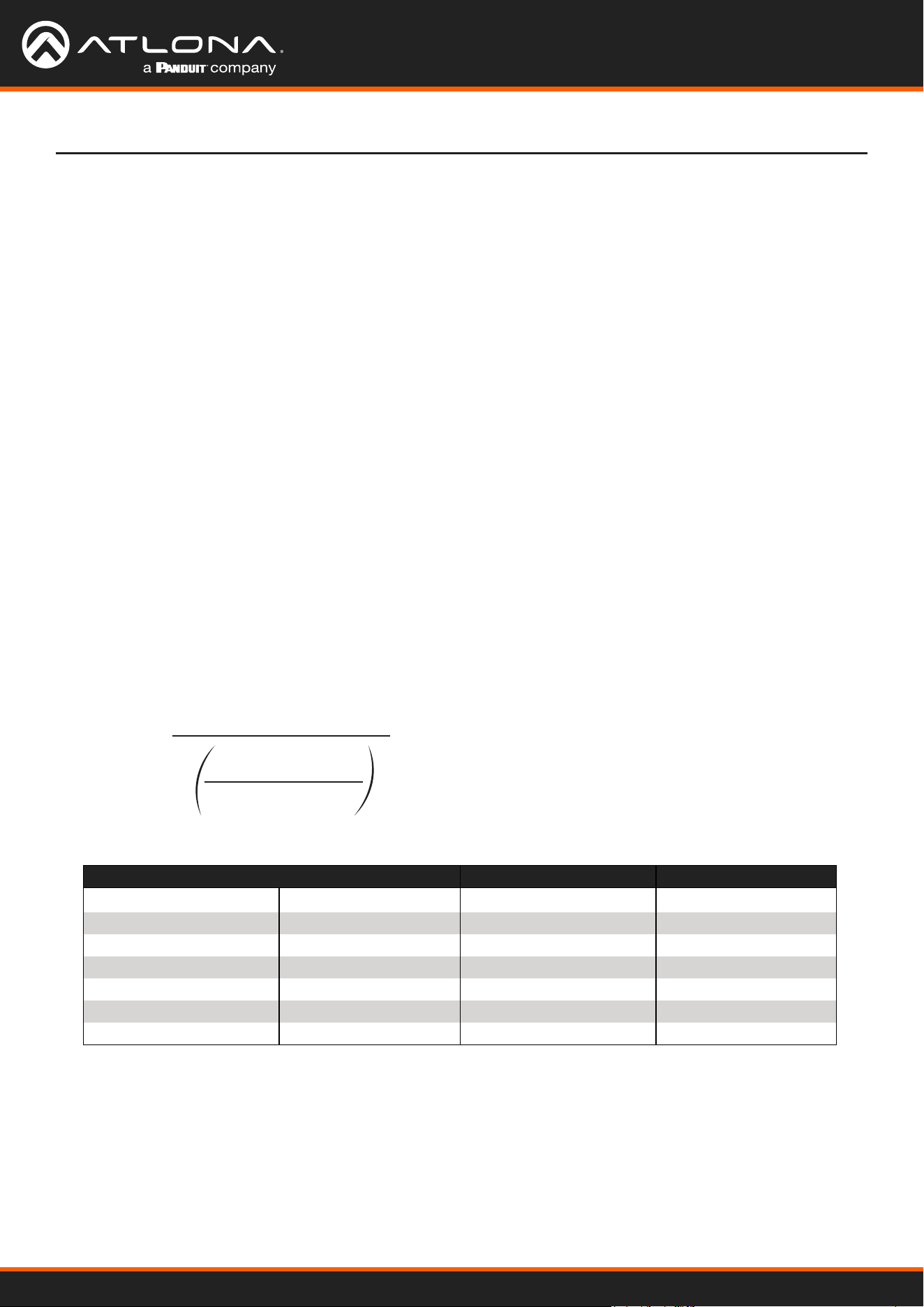
Using OmniStream
™
with Velocity
™
Device Manager
150
Appendix
FEC Details
Matrix Size, Overhead, and Latency
FEC and Video Bitrate
• FEC can only work if a single packet from each row/column is missing. Multiple packets missing from each row/
column will cause FEC to fail.
• Due to the above, a smaller matrix is more robust, as there is a better chance of errors not occurring in the same
row/column.
• FEC has a bitrate overhead that is inversely proportional to the matrix size: the bigger the matrix, the less bitrate
overhead is generated.
• FEC has a latency overhead that is directly proportional to the matrix size: the bigger the matrix, the more
latency is introduced.
» As of v1.0.0, OmniStream does not explicitly synchronize audio and video. Therefore, FEC conguration can
have a noticeable impact on lip sync. The tables below should be used to keep the audio/video lip sync as
tight as possible.
• FEC latency overhead is also inversely proportional to bitrate: the higher the bitrate, the less FEC latency is
introduced.
» For applications where lip sync is very critical, using a higher audio sampling rate, and thus a higher audio
bitrate, can result in more accurate lip sync.
• The bitrate congured on the video encoder includes FEC overhead and will automatically adjust itself depending
on the bitrate needed for FEC.
• FEC overhead can be calculated using the following formulas:
• The following table provides a few examples of how this works.
Video rate =
Configured bit rate
1 +
Rows + Columns
Rows x Columns
FEC rate = Configured bit rate - Video rate
FEC / matrix usage Congured bit rate Used for video Used for FEC
FEC disabled 900 Mbps 900 Mbps 0 Mbps
FEC enabled, 4x4 900 Mbps 600 Mbps 300 Mbps
FEC enabled, 10x10 900 Mbps 750 Mbps 150 Mbps
FEC enabled, 20x20 900 Mbps 818 Mbps 82 Mbps
FEC enabled, 4x4 450 Mbps 300 Mbps 150 Mbps
FEC enabled, 10x10 450 Mbps 375 Mbps 75 Mbps
FEC enabled, 20x20 450 Mbps 409 Mbps 41 Mbps
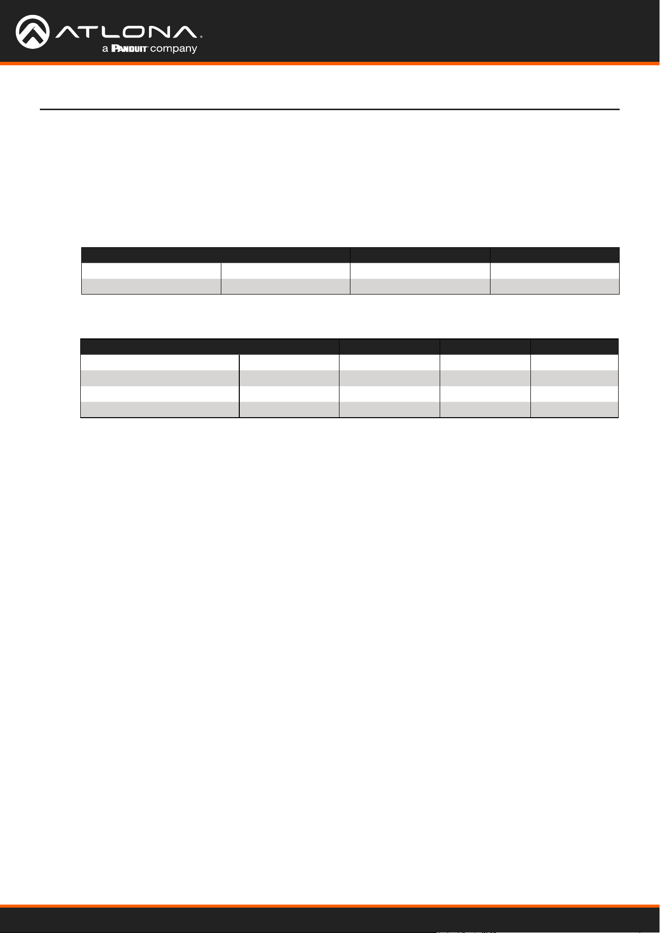
Using OmniStream
™
with Velocity
™
Device Manager
151
Appendix
FEC, Latency, and Lip Sync
• In order for FEC to work, the matrix must be lled in order to calculate the FEC packets. This introduces some
additional latency. Due to high bitrates, this is not noticeable for video, but can be very signicant for audio.
Therefore, Atlona recommends either leaving FEC disabled for audio or using a very small matrix.
• Latency calculations are complex. The tables below provide some common working benchmarks. In order to
minimize lip sync issues, try to match the additional latencies for video and audio as closely as possible.
» Video - additional video latency for enabling FEC using various matrix sizes.
• It is recommended to keep lip sync within ±1 frame of video to prevent any noticeable syncing issues.
• Examples of good choices to minimize lip sync issues are:
» Video congured for 450 Mbps, FEC 10x10; Audio is 2 channel PCM, 192 kHz, FEC 1x4: 6.40 ms – 7.81 ms
= -1.41 ms
» Video congured for 900 Mbps, FEC 10x10; Audio is 2 channel PCM, 48 kHz, FEC disabled: 6.40 ms – 0 ms
= 6.40 ms
» Audio - additional audio latency for enabling FEC using various matrix sizes.
Congured bit rate 4x4 10x10 20x20
900 Mbps 0.64 ms 3.20 ms 11.74 ms
450 Mbps 1.28 ms 6.40 ms 23.47 ms
Format 1x4 2x4 4x4 10x10
2 channel PCM, 44.1 kHz 34.01 ms 68.03 ms 136.10 ms 850.30 ms
2 channel PCM, 48 kHz 31.25 ms 62.50 ms 125.00 ms 781.30 ms
2 channel PCM, 96 kHz 15.63 ms 31.25 ms 62.50 ms 390.60 ms
2 channel PCM, 192 kHz 7.81 ms 15.63 ms 31.25 ms 195.30 ms
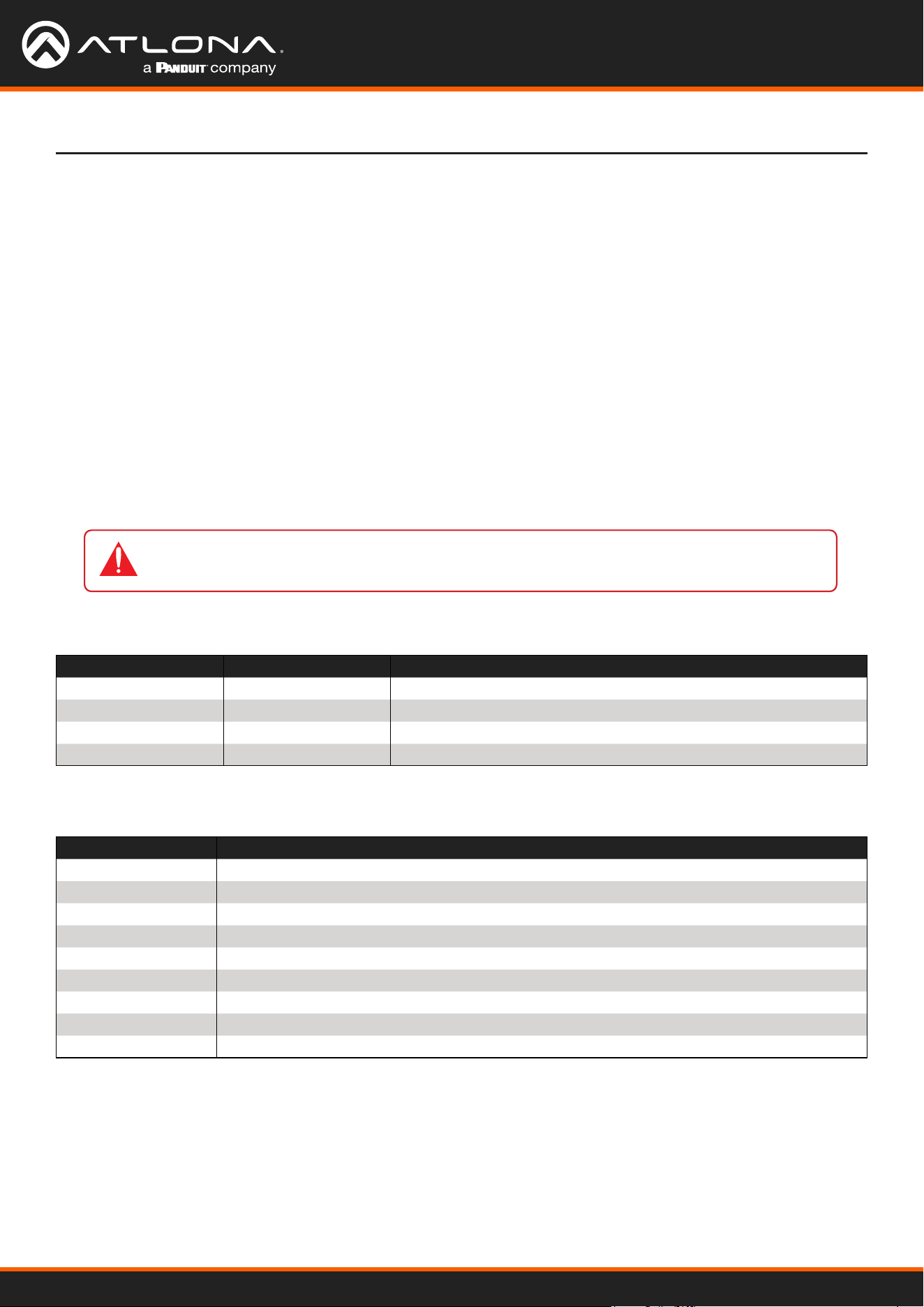
Using OmniStream
™
with Velocity
™
Device Manager
152
Appendix
Dierentiated Services Code Point (DSCP) is a method of managing network trac, in addition to providing Quality
of Service (QoS) within the Layer-3 (Network Layer) of the OSI network model. DSCP uses the 6-bit Dierentiated
Services (DS) eld in the IP header in order to determine packet classication/priority. Normally, all routers and
switches will forward network trac to the proper destination with the same priority, no matter what type of data it is.
This methodology is what is known as Best Eort.
The Best Eort setting will provide normal priority for data packets, while other settings will raise the priority on
data packets. However, it should be noted that a higher priority setting on one type of data type may also result in
data packet loss for other data types, depending upon network trac.
When QoS or dierentiated services policy is used, all network devices such as routers, networks switches, and
end-devices must be congured properly in accordance with QoS policies on the network. There are two main
methodologies for tagging trac: Assured Forwarding (AF) and Class Selectors (CS).
The tables below provide a list of the available selections and their description.
IMPORTANT: Consult the IT administrator as to what methods to use and the required settings
for each encoder on the network.
Dierentiated Services Code Point
Selection Queue Classication Drop Probability
AF11 Class 1 Low
AF21 Class 2 Low
AF31 Class 3 Low
AF41 Class 4 Low
Selection Class Selector Name
CS0 / Best Effort Routine
CS1 Priority
CS2 Immediate
CS3 Flash
CS4 Flash Override
CS5 Critical
CS6 Interwork Control
CS7 Network Control
EF Expedited Forwarding
Table 1 - Assured Forwarding
Table 2 - Class Selectors

US International
atlona.com • 408.962.0515 • 41.43.508.4321
35303-R2