PLANNING GUIDE
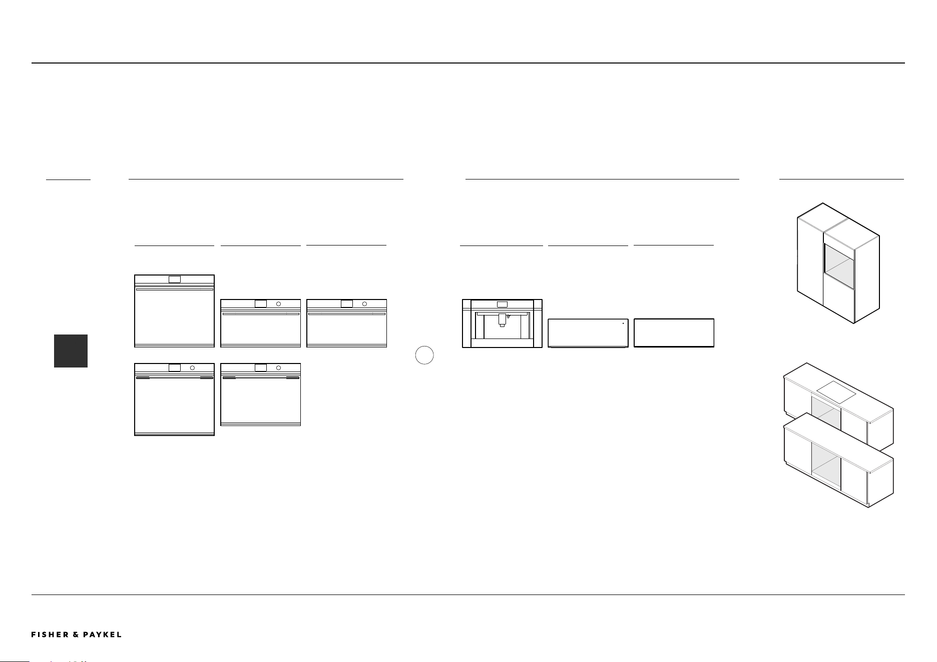
30" BUILT-IN OVENS ANDCOMPANIONS
MINIMAL
SERIES 9 & 11
OVEN | OB30SDPTDB1 | OB30SDPTB1
STEAM OVEN | OS30SDTDB1, OS30NDTDB1
SPEED OVEN | OM30NDTDB1
BUILT-IN COFFEE MAKER | EB24DSXBB1
TRIM KIT | TK7630NDB2
WARMING DRAWER | WB30SDB1-SET
VACUUM SEAL DRAWER | VB30SDB1-SET

© FISHER & PAYKEL LIMITED 2024 PAGE 290003336E PLANNING GUIDE COOKING - VERSION E - SEPTEMBER 2024
PLANNING GUIDE | OVENS AND COMPANIONS, 30"
This comprehensive Planning Guide provides you with the framework and tools to achieve your desired design outcome with Fisher & Paykel appliances. In this guide, you will
find a range of conceptual, detailed and dimensional product information to bring your ideas to life and create spaces that truly reflect your vision.
CONCEPT DESIGN PAGE DEVELOPED AND DETAILED DESIGN PAGE
CONTENTS
The models shown in this Planning Guide may not be available in all markets and are subject to change at any time. Product specifications may vary from those shown. This Planning Guide should not be used as installation guidance for any
product. Further information is required to safely and correctly install the products featured here. Specific installation guidance will be available on our website fisherpaykel.com
Design Choices
Ovens and Companions - ALL MODELS 4
Configurations - ALL MODELS 5
Overview - ALL MODELS 6
Specification Guides
Oven 8
Combination Steam Oven 9
Combination Steam Oven 10
Convection Speed Oven 11
Built-in Coee Maker with Trim Kit 12
Warming Drawer 13
Vacuum Seal Drawer 14
Dimensions - ALL MODELS 15
Power, Weight and Capacity - ALL MODELS 16
Data Sheets
Oven 18
Combination Steam Oven 19
Combination Steam Oven 20
Convection Speed Oven 21
Built-in Coee Maker with Trim Kit 22
Warming Drawer 23
Vacuum Seal Drawer 24
Planning Considerations
Cabinetry Preparation - ALL MODELS 26
Configurations - ALL MODELS 27
Oven 28
Combination Steam Oven 29
Combination Steam Oven 30
Convection Speed Oven 31
Built-in Coee Maker with Trim Kit 32
Warming Drawer 33
Vacuum Seal Drawer 34
Services
Power Cord Length and Location - COMPANIONS 36
Power Cord Length and Location - OVENS 37
DEVELOPED AND DETAILED DESIGN PAGE
i
i

© FISHER & PAYKEL LIMITED 2024 PAGE 390003336E PLANNING GUIDE COOKING - VERSION E - SEPTEMBER 2024
DESIGN CHOICES
Design Choices
© FISHER & PAYKEL LIMITED 2024 PAGE 490003336E PLANNING GUIDE COOKING - VERSION E - SEPTEMBER 2024
DESIGN CHOICES | OVENS AND COMPANIONS, 30" ALL MODELS
Ovens and Companions - ALL MODELS
The models shown in this Planning Guide may not be available in all markets and are subject to change at any time. Product specifications may vary from those shown. This Planning Guide should not be used as installation guidance for any
product. Further information is required to safely and correctly install the products featured here. Specific installation guidance will be available on our website fisherpaykel.com
+
BLACK
INSTALLATION IN WALL
INSTALLATION
UNDER-BENCH
OVEN COMBINATION STEAM
CONVECTION SPEED
BUILT-IN COFFEE MAKER WARMING DRAWER
INSTALLATION OPTIONSCOLOUR OVENS COMPANIONS
VACUUM SEAL DRAWER
<< CONTENTS
© FISHER & PAYKEL LIMITED 2024 PAGE 590003336E PLANNING GUIDE COOKING - VERSION E - SEPTEMBER 2024
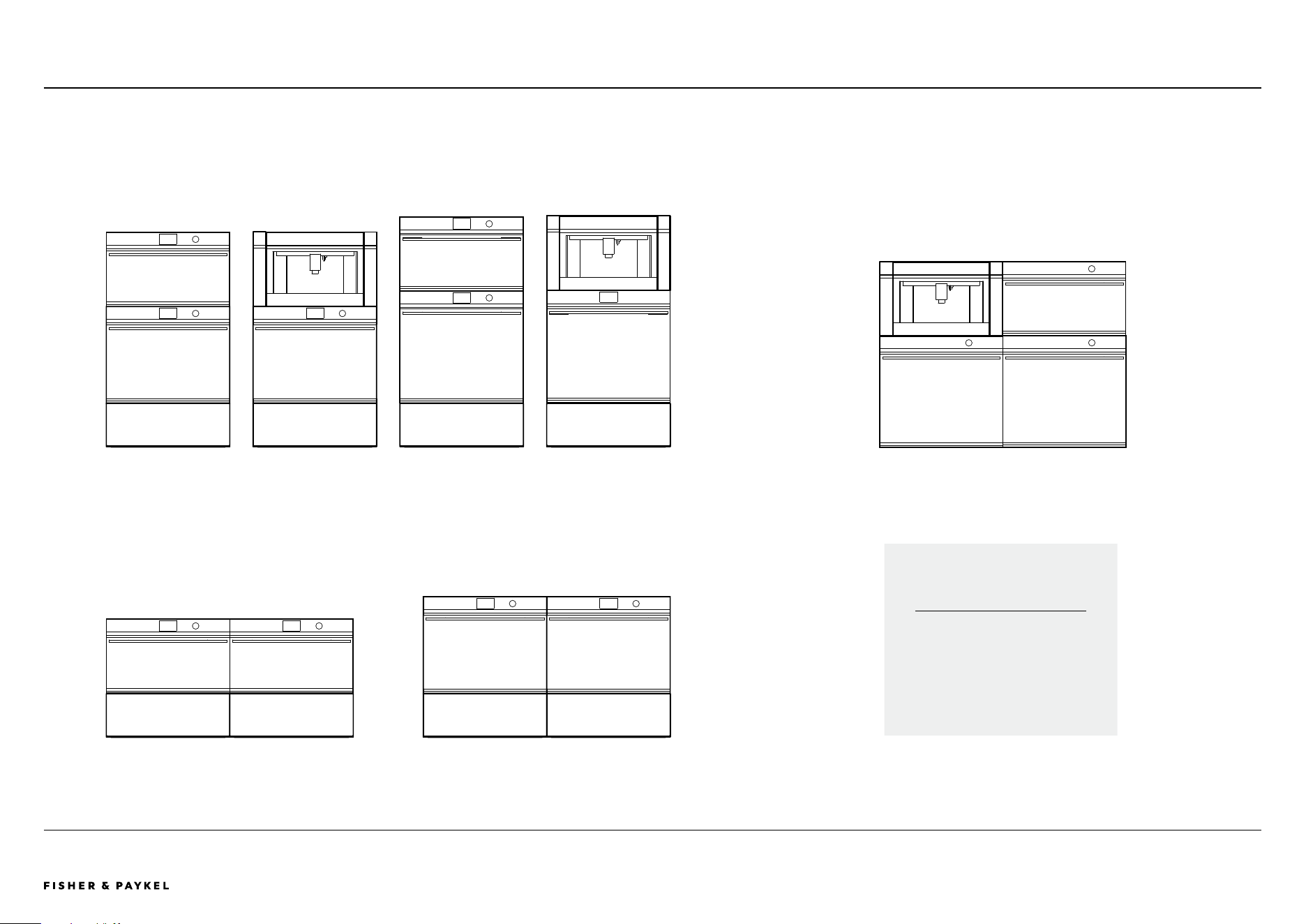
STACKED INSTALLATION GRID INSTALLATION
ROW INSTALLATION
CONSIDERATIONS
Different configurations possible,
consider heights for row and grid
installations.
Note: Stack Height is overall product height with minimum clearance above appliance front panel to upper cabinetry front panel or appliance.
Stack Height
52 13/32" (1331mm)
ALL MODELSDESIGN CHOICES | CONFIGURATIONS, 30"
Configurations - ALL MODELS
The models shown in this Planning Guide may not be available in all markets and are subject to change at any time. Product specifications may vary from those shown. This Planning Guide should not be used as installation guidance for any
product. Further information is required to safely and correctly install the products featured here. Specific installation guidance will be available on our website fisherpaykel.com
Stack Height
56 1/32" (1423mm)
Stack Height
45 11/32" (1152mm)
Stack Height
28 25/32" (731mm)
Stack Height
26 21/32" (677mm)
Stack Height
56 1/32" (1423mm)
Stack Height
52 13/32" (1331mm)
<< CONTENTS
The models shown in this Planning Guide may not be available in all markets and are subject to change at any time. Product specifications may vary from those shown. This Planning Guide should not be used as installation guidance for any
product. Further information is required to safely and correctly install the products featured here. Specific installation guidance will be available on our website fisherpaykel.com
© FISHER & PAYKEL LIMITED 2024 PAGE 690003336E PLANNING GUIDE COOKING - VERSION E - SEPTEMBER 2024
DESIGN CHOICES | OVERVIEW, 30" ALL MODELS
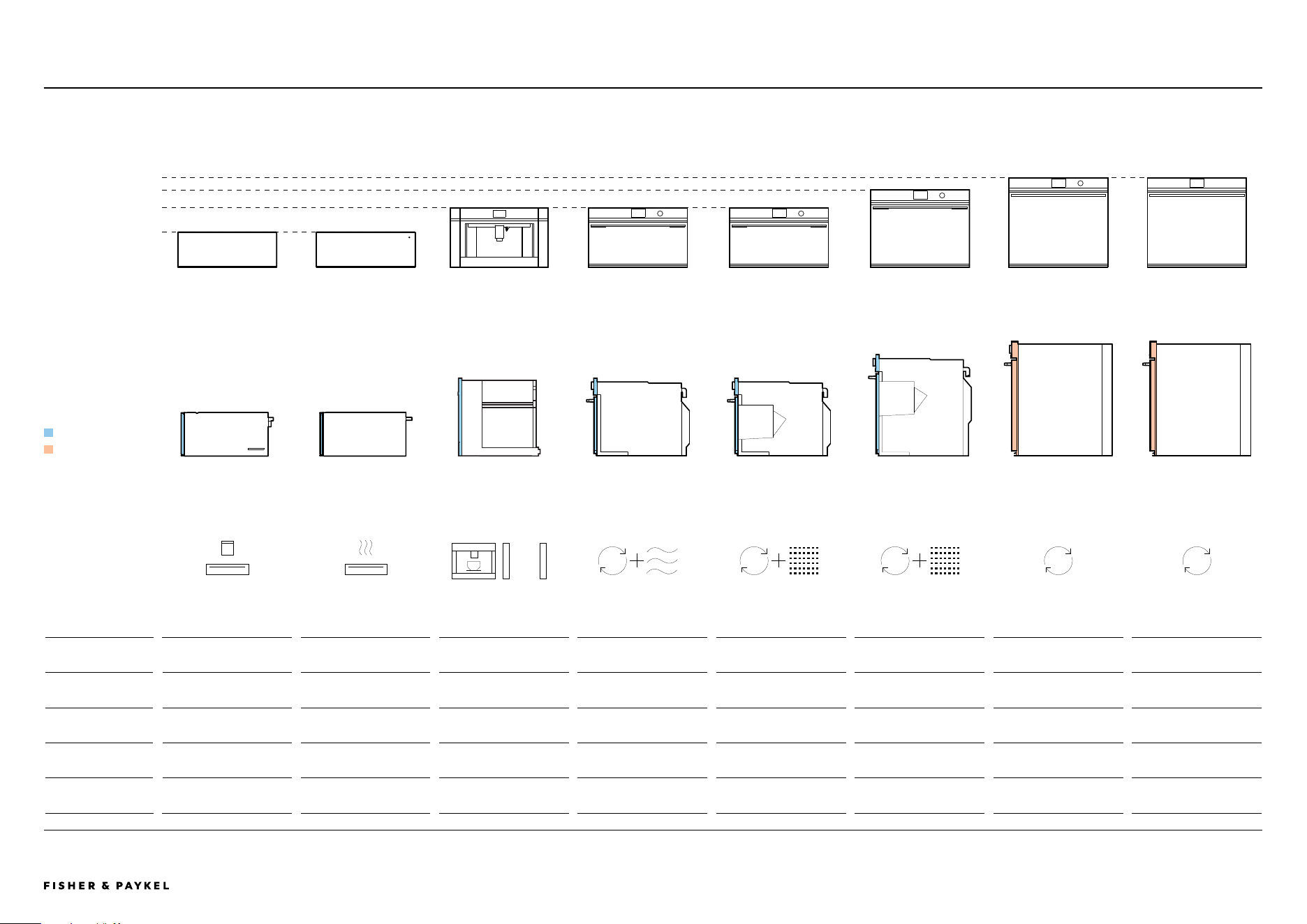
Overview - ALL MODELS
FRONT ELEVATION
WARMING DRAWER VACUUM SEAL DRAWER BUILT-IN COFFEE MAKER
WITH TRIM KIT
CONVENCTION SPEED OVEN COMBINATION STEAM
OVEN
COMBINATION STEAM
OVEN
OVEN OVEN
Series Series 9 Series 9 Series 9 Series 9 Series 9 Series 11 Series 9 Series 9
Model Code WB30SDB1-SET VB30SDB1-SET EB24DSXBB1 (TK7630NDB2) OM30NDTDB1 OS30NDTDB1 OS30SDTDB1 OB30SDPTDB1 OB30SDPTB1
Interface - - 4.3" Touchscreen 5" Touchscreen, Dial Control 5" Touchscreen, Dial Control 5" Touchscreen, Dial Control 5" Touchscreen, Dial Control 5" Touchscreen
Height 10 11/16" (271mm) 10 11/16" (271mm) 18" (458mm) 18" (458mm) 18" (458mm) 23 9/16" (598mm) 27 3/16" (690mm) 27 3/16" (690mm)
Front Panel Thickness 13/16" (20mm) 13/16" (20mm) 13/16" (20mm) 13/16" (20mm) 13/16" (20mm) 13/16" (20mm) 1 9/16" (40mm) 1 9/16" (40mm)
SIDE ELEVATION
Front Panel Thickness
13/16" (20mm)
1 9/16" (40mm)
<< CONTENTS

© FISHER & PAYKEL LIMITED 2024 PAGE 790003336E PLANNING GUIDE COOKING - VERSION E - SEPTEMBER 2024
SPECIFICATION GUIDE
SERIES 9 & 11
Specification Guides
The models shown in this Planning Guide may not be available in all markets and are subject to change at any time. Product specifications may vary from those shown. This Planning Guide should not be used as installation guidance for any
product. Further information is required to safely and correctly install the products featured here. Specific installation guidance will be available on our website fisherpaykel.com
© FISHER & PAYKEL LIMITED 2024 PAGE 890003336E PLANNING GUIDE COOKING - VERSION E - SEPTEMBER 2024
SPECIFICATION GUIDE | OVEN, 30"
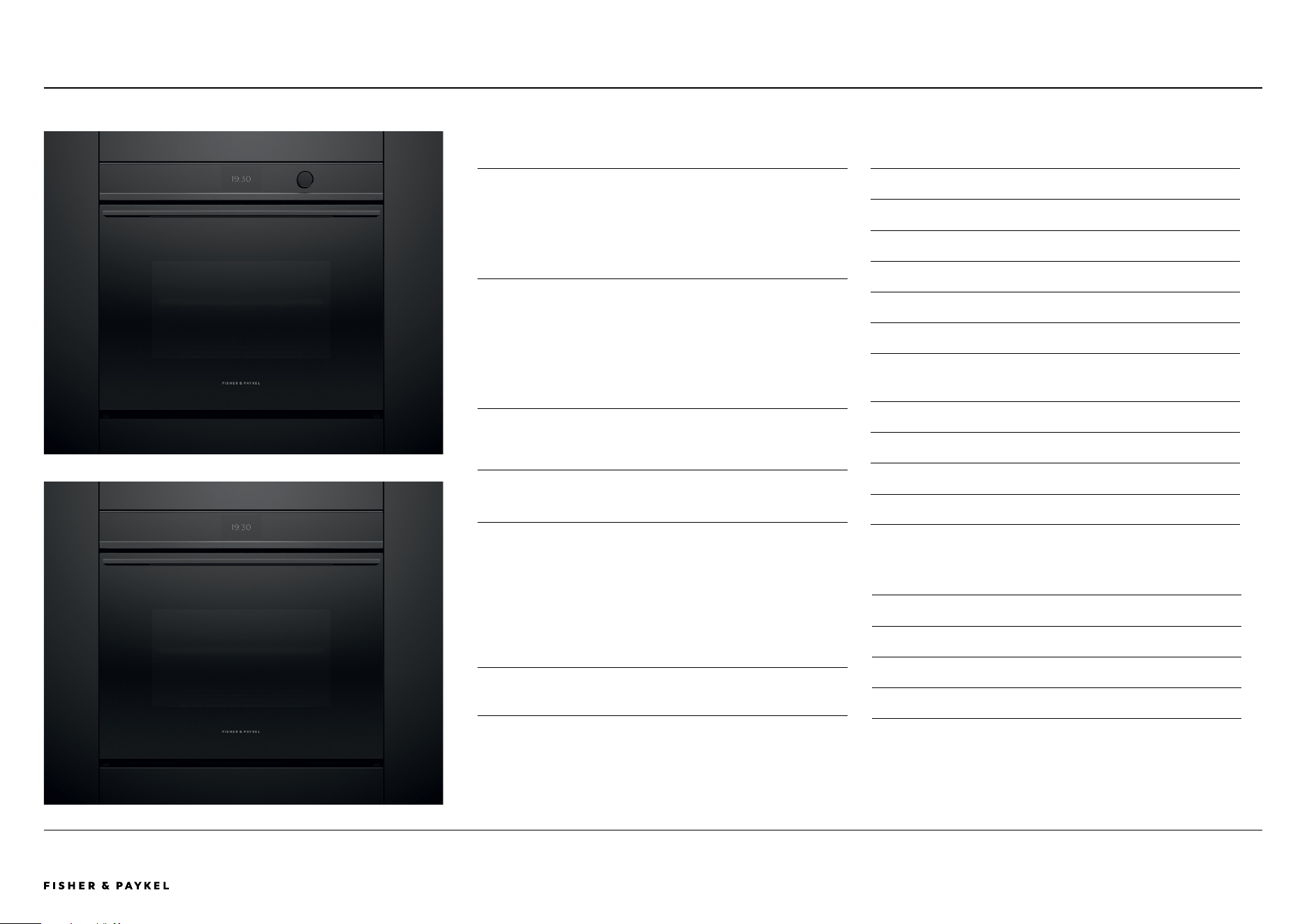
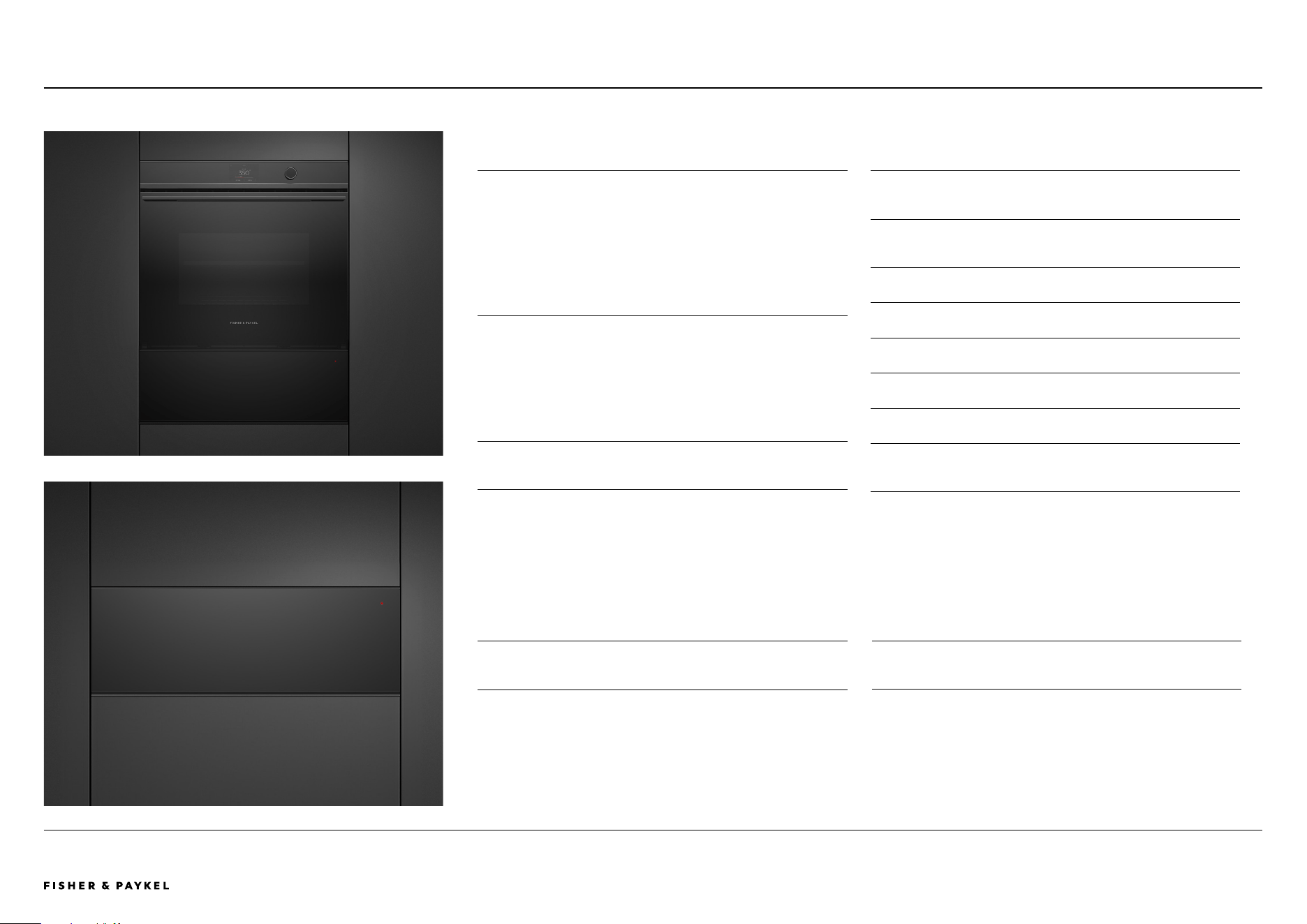
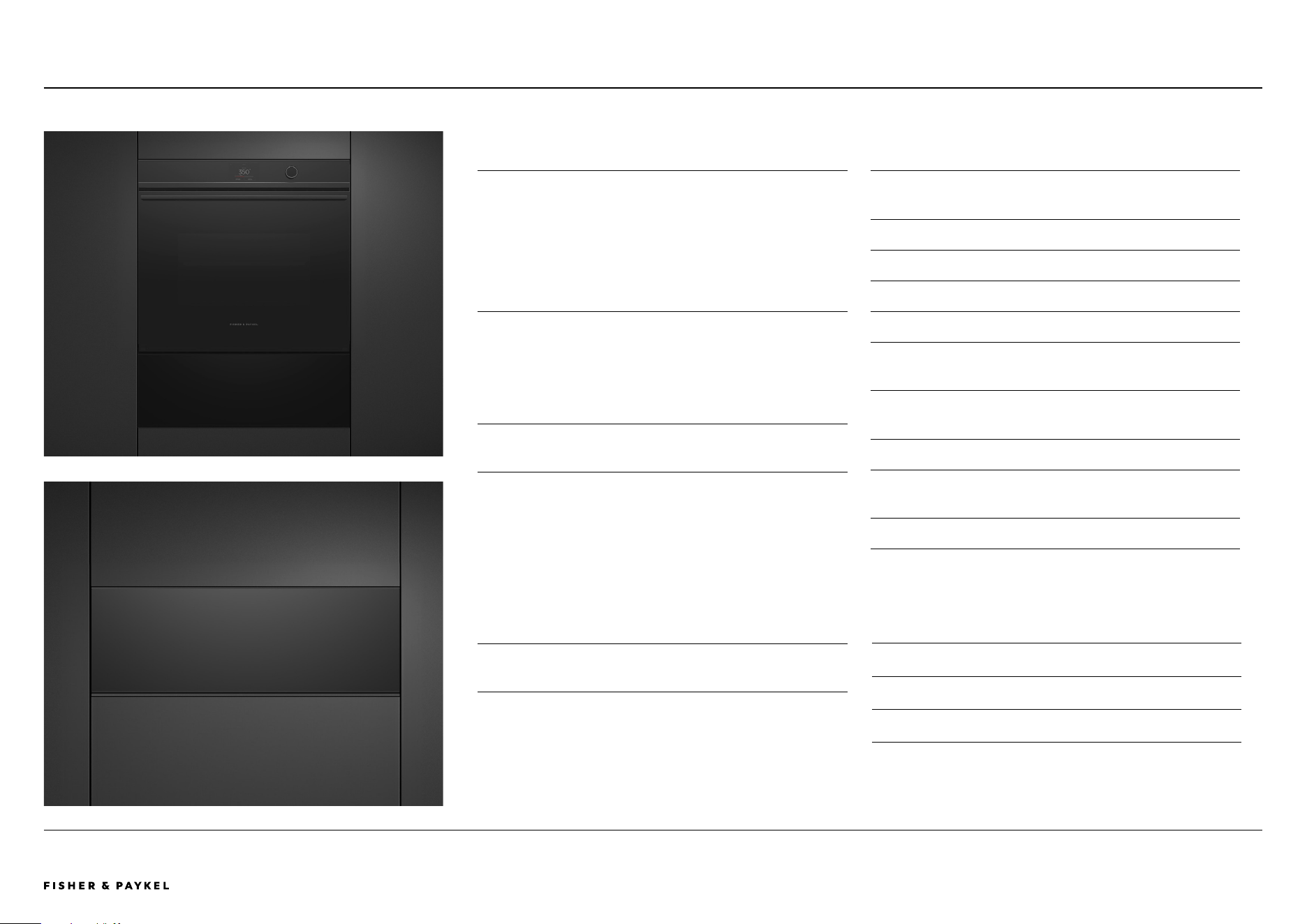
Oven
OVERVIEW
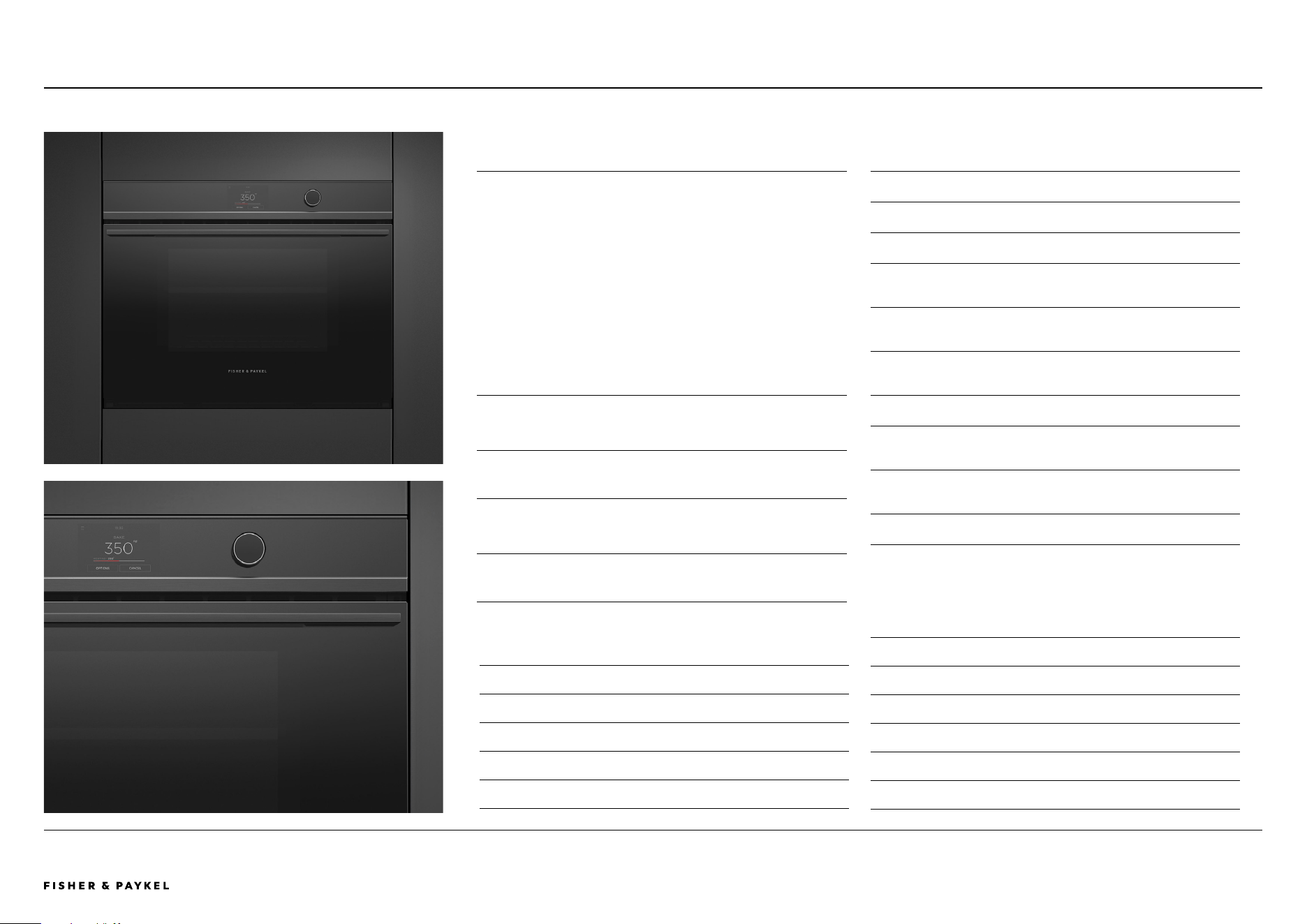
Enhance your kitchen design with the 30” Oven. Refined
styling means it matches seamlessly with our Minimal kitchen
appliances to create a coherent, considered look and feel.
Intuitive controls and the performance to deliver perfect
results make this oven beautiful to use.
PRODUCTS
OB30SDPTDB1
Built-In Oven, 30", 17 Function, 4.1 cu ft, Dial Controls,
Touchscreen
OB30SDPTB1
Built-In Oven, 30", 17 Function, 4.1 cu ft, Touchscreen
SERIES & STYLE
Series 9
Minimal
FEATURES
1
Designed to fit flush with cabinetry
2 Styled to perfectly match our Minimal kitchen appliances
3 Generous 4.1cu ft total capacity
4 High-resolution, user-friendly touch display
5 Guided cooking and recipes
6 Perfect results from a variety of oven functions
7 Even heat distribution throughout with AeroTech™
technology
8 Self-cleaning
9 CoolTouch door
"0 Wi-Fi/Connected capability through the SmartHQ™ app
"1 Soft open and close door
ACCESSORIES
1
Full Extension Sliding Shelves*
2 Self-cleaning-proof side racks*
3 Roasting dish, tray and rack*
4 Wired Temperature Sensor*
*Included with product
Oven OB30SDPTDB1 with Dial Controls
Oven OB30SDPTB1
OB30SDPTDB1 | OB30SDPTB1
<< CONTENTS
The models shown in this Planning Guide may not be available in all markets and are subject to change at any time. Product specifications may vary from those shown. This Planning Guide should not be used as installation guidance for any
product. Further information is required to safely and correctly install the products featured here. Specific installation guidance will be available on our website fisherpaykel.com
© FISHER & PAYKEL LIMITED 2024 PAGE 990003336E PLANNING GUIDE COOKING - VERSION E - SEPTEMBER 2024
SPECIFICATION GUIDE | COMBINATION STEAM OVEN, 30"
Combination Steam Oven
OS30SDTDB1
OVERVIEW
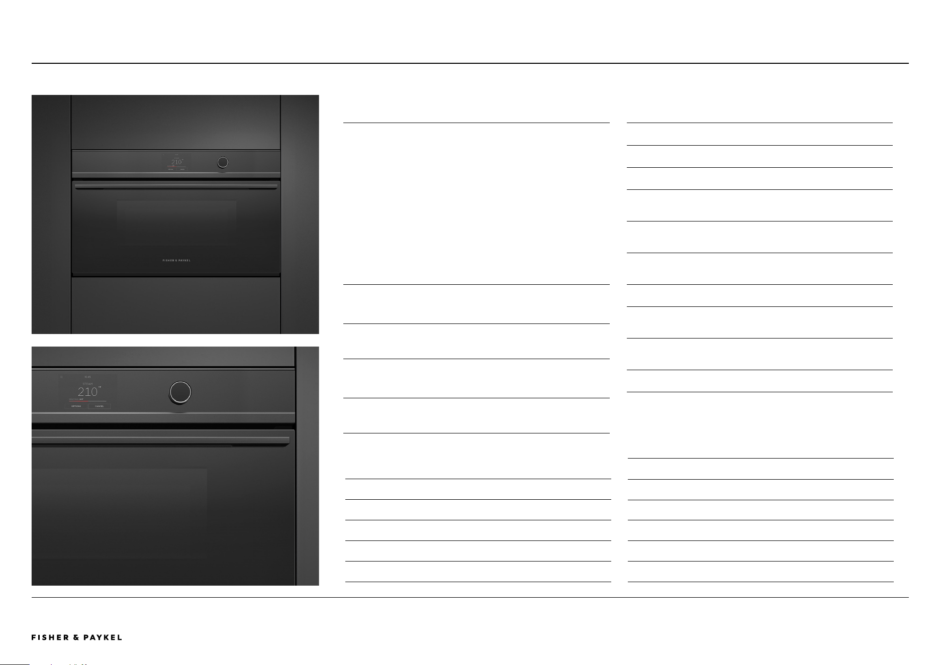
With subtle Minimal styling, the Combination Steam Oven fits
seamlessly into any kitchen. As a companion product, this
oven is designed to install easily and fit perfectly with other
companion products such as the Combination Microwave
Oven, or Vacuum Seal Drawer. It features 23 functions,
including steam-only, convection-only, or a combination of
both. Reduce the need for oils and fats with six standalone
steam functions, perfect for creating flavorful and healthy
restaurant-quality meals at home. Beautiful to use, the large
5” touchscreen interface has simple and intuitive guided
cooking, helping to ensure perfect results.
PRODUCTS
OS30SDTDB1
Combination Steam Oven, 30", 23 Function
SERIES & STYLE
Series 11
Minimal
FEATURES
1
Minimal styling, designed to fit flush
2 Generous 3cu ft total capacity with six shelf positions
3 Intuitive, large 5" touchscreen display with illuminated dial
4 23 oven functions including Steam, Sous Vide, Air Fry and
Crisp Regenerate
5 Guided touchscreen cooking makes it simple to cook by
food, function or recipe
6 Moisture control and even heat distribution thanks to
ActiveVent and AeroTech™ technology
7 47.3 fl oz water tank
8 Wi-Fi enabled and works with the SmartHQ™ app for
remote control and notifications
9 Steam Clean function ensures a spotless oven with minimal
effort
"0 Soft open and close door
ACCESSORIES
6
Perforated Large Steam Dish*
7 Perforated Small Steam Dish*
8 Large Steam Dish*
9 Wired Temperature Sensor*
"0 Catalytic Panel*
"1 Descale solution* - 2 sachets (Part 580925)
*Included with product
ACCESSORIES
1
2x Full Extension Sliding Shelves*
2 Step Down Wire Shelf*
3 Broil Pan*
4 Broil Rack*
5 Broil Grid*
<< CONTENTS
The models shown in this Planning Guide may not be available in all markets and are subject to change at any time. Product specifications may vary from those shown. This Planning Guide should not be used as installation guidance for any
product. Further information is required to safely and correctly install the products featured here. Specific installation guidance will be available on our website fisherpaykel.com
© FISHER & PAYKEL LIMITED 2024 PAGE 1090003336E PLANNING GUIDE COOKING - VERSION E - SEPTEMBER 2024
Combination Steam Oven
SPECIFICATION GUIDE | COMBINATION STEAM OVEN, 30"
OS30NDTDB1
OVERVIEW
With subtle Minimal styling, the Combination Steam Oven fits
seamlessly into any kitchen. As a companion product, this
oven is designed to install easily and fit perfectly with other
companion products such as the Combination Microwave
Oven, or Vacuum Seal Drawer. It features 23 functions,
including steam-only, convection-only, or a combination of
both. Reduce the need for oils and fats with six standalone
steam functions, perfect for creating flavorful and healthy
restaurant-quality meals at home. Beautiful to use, the large
5” touchscreen interface has simple and intuitive guided
cooking, helping to ensure perfect results.
PRODUCTS
OS30NDTDB1
Combination Steam Oven, 30", 23 Function
SERIES & STYLE
Series 9
Minimal
FEATURES
1
Minimal style, designed to fit flush with cabinetry
2 Generous 1.9 cu ft total capacity with four shelf positions
3 Intuitive, large 5" touchscreen display with illuminated dial
4 23 oven functions including Steam, Sous Vide, Air Fry and
Crisp Regenerate
5 Guided touchscreen cooking makes it simple to cook by
food, function or recipe
6 Moisture control and even heat distribution thanks to
ActiveVent and AeroTech™ technology
7 47.3 fl oz water tank
8 Wi-Fi enabled and works with the SmartHQ™ app for
remote control and notifications
9 Steam Clean function ensures a spotless oven with minimal
effort
"0 Soft open and close door
ACCESSORIES
6
Perforated Large Steam Dish*
7 Perforated Small Steam Dish*
8 Large Steam Dish*
9 Wired Temperature Sensor*
"0 Catalytic Panel*
"1 Descale solution* - 2 sachets (Part 580925)
*Included with product
ACCESSORIES
1
Full Extension Sliding Shelf*
2 Wire Shelf*
3 Broil Pan*
4 Broil Rack*
5 Perforated Large Steam Dish*
<< CONTENTS
The models shown in this Planning Guide may not be available in all markets and are subject to change at any time. Product specifications may vary from those shown. This Planning Guide should not be used as installation guidance for any
product. Further information is required to safely and correctly install the products featured here. Specific installation guidance will be available on our website fisherpaykel.com
© FISHER & PAYKEL LIMITED 2024 PAGE 1190003336E PLANNING GUIDE COOKING - VERSION E - SEPTEMBER 2024
Convection Speed Oven
OM30NDTDB1
SPECIFICATION GUIDE | CONVECTION SPEED OVEN, 30"
OVERVIEW
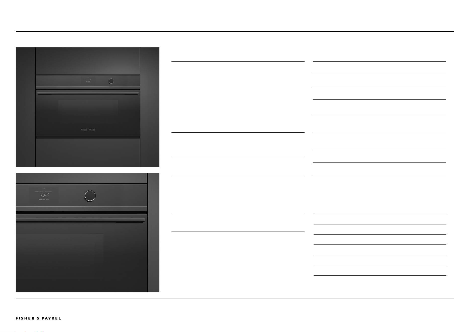
With subtle Minimal styling, the Convection Speed Oven fits
seamlessly into any kitchen. As a companion product, this
Speed Oven is designed to install easily and fit perfectly with
other companion products such as the Combination Steam
Oven, or Vacuum Seal Drawer. A flexible appliance that pairs
the speed of microwave cooking with oven technology,
which can crisp and brown as it cooks. Featuring 22 cooking
functions on an intuitive touch display for easy programming
of desired cooking mode and duration.
PRODUCTS
OM30NDTDB1
Convection Speed Oven, 30", 22 Function
SERIES & STYLE
Series 9
Minimal
FEATURES
1
Minimal style, designed to fit flush with cabinetry
2 1.7cu ft total capacity
3 Intuitive, large 5" touchscreen display with illuminated dial
4 Four microwave-only functions, 14 traditional oven
functions, and four combination functions
5 A Wired Temperature Sensor precisely monitors cooking in
real time
6 Guided cooking, with the option to access additional
functionality via the SmartHQ™ app
7 Wi-Fi/Connected capability through the SmartHQ™ app
8 Soft open and close door
ACCESSORIES
1
Wire Shelf*
2 Chrome Shelf Runners*
3 Step Down Wire Shelf*
4 Broil Rack*
5 Glass Tray*
6 Wired Temperature Sensor*
*Included with product
<< CONTENTS
The models shown in this Planning Guide may not be available in all markets and are subject to change at any time. Product specifications may vary from those shown. This Planning Guide should not be used as installation guidance for any
product. Further information is required to safely and correctly install the products featured here. Specific installation guidance will be available on our website fisherpaykel.com
© FISHER & PAYKEL LIMITED 2024 PAGE 1290003336E PLANNING GUIDE COOKING - VERSION E - SEPTEMBER 2024
SPECIFICATION GUIDE | BUILT-IN COFFEE MAKER WITH TRIM KIT, 30"
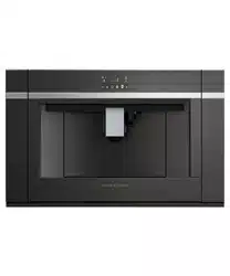
Built-in Coee Maker with Trim Kit
EB24DSXBB1 | TK7630NDB2
OVERVIEW
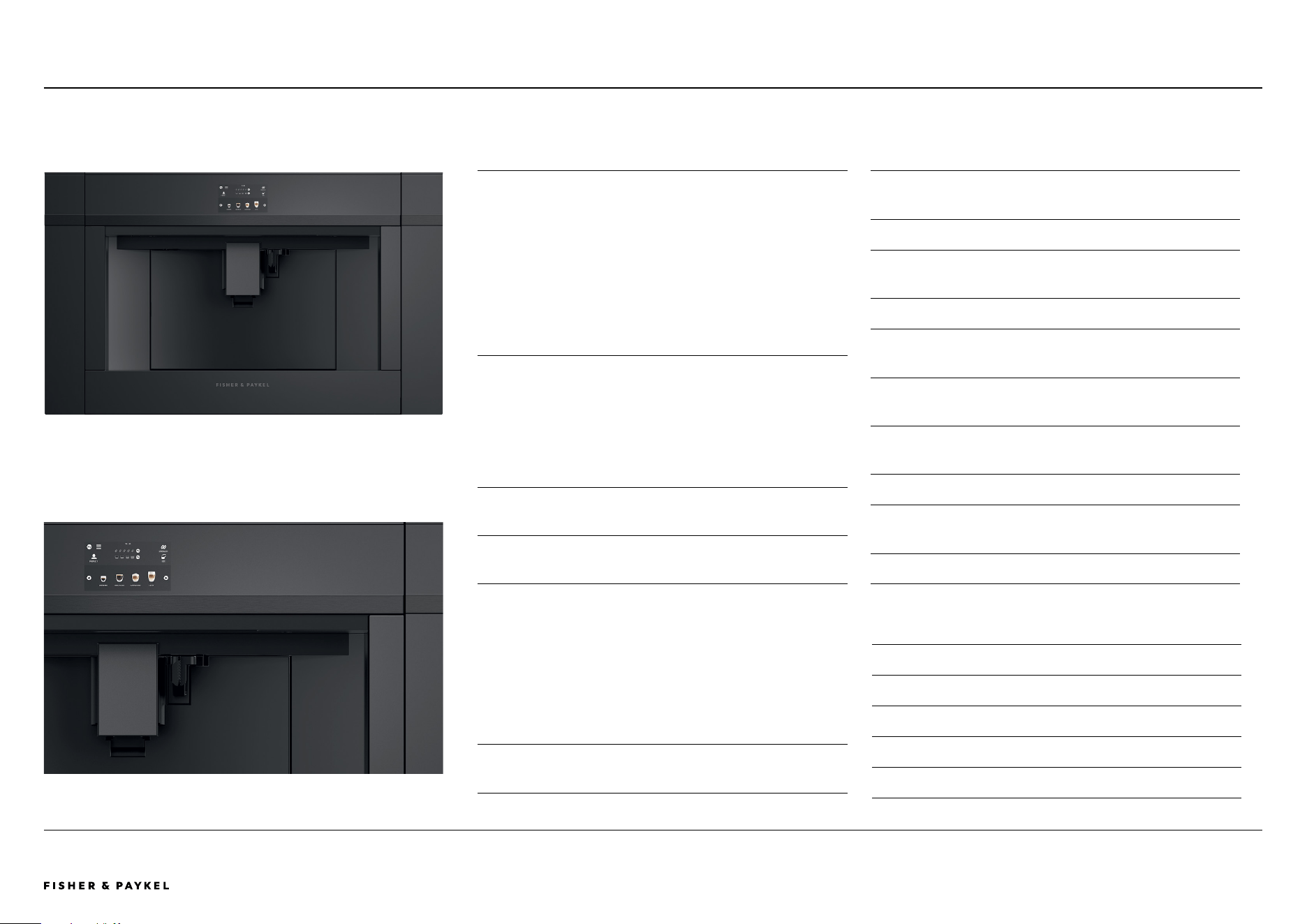
The Built-in Coee Maker features a stylish black finish and
can be installed in multiple configurations to suit kitchen
design and preference. With 13 beverage options, our Coee
Maker is designed to consistently pour delicious coee –
from Flat White to Latte or Americano. Favourite coee
styles are memorized for a fast brew with the push of a
button. A programmable timer turns the Coee Maker on at
the ideal time each day, while the conical burr grinder
delivers a consistent grind for a perfect coee.
PRODUCTS
EB24DSXBB1
Built-in Coee Maker, 24", Touchscreen, Black
TK7630NDB2
Companion Trim Kit, 30", Black
Note: Trim Kit purchased separately.
SERIES & STYLE
Series 9
Contemporary
FEATURES
1
Designed to pair perfectly with 30" ovens and companion
products
2 Stylish black finish
3 Install in multiple configurations to suit your kitchen design
4 Intuitive touch display
5 13 functions to suit any taste and selection – from Espresso
to Latte
6 Personalized coffee and smart self-learning menu
preferences
7 Stainless steel conical burr grinder with 13 coarseness
positions
8 15 bar pump pressure
9 Self-cleaning function and easy to empty coffee grounds
container and drip tray
"0 84ft oz (2.5L) water tank capacity
ACCESSORIES
1
Thermal milk jug 17ft oz (0.5L)*
2 Water filter*
3 Coffee spoon*
4 Extractable steam outlet*
5 Descaling agent bottle*
*Included with product
<< CONTENTS
The models shown in this Planning Guide may not be available in all markets and are subject to change at any time. Product specifications may vary from those shown. This Planning Guide should not be used as installation guidance for any
product. Further information is required to safely and correctly install the products featured here. Specific installation guidance will be available on our website fisherpaykel.com
© FISHER & PAYKEL LIMITED 2024 PAGE 1390003336E PLANNING GUIDE COOKING - VERSION E - SEPTEMBER 2024
SPECIFICATION GUIDE | WARMING DRAWER, 30"
Warming Drawer
WB30SDB1-SET
Warming Drawer, WB30SDB1-SET Black Glass, paired with Built-in Oven OB30SDPTDB1
OVERVIEW
Designed to complement our Minimal and Contemporary
ovens, these warming drawers are handle-free, and push-to-
open for a coherent, considered look. Beautiful to use, with
capacitive touch controls and six tailored functions for
warming, proofing, dehydrating and slow cook. Pair with
other companion products to create a kitchen suite for every
need.
PRODUCTS
WB30SDB1-SET
Warming Drawer, 30", Black Glass
SERIES & STYLE
Series 9
Minimal
FEATURES
1
Styled to perfectly match our Minimal and Contemporary
kitchen appliances
2 Seamless pairing with other companion products in either
stylish black reflective glass or brushed stainless steel
3 Push-to-open drawer
4 Easy-to-use capacitive touch controls
5 Automatic timing and switch-off functionality
6 Easy-to-clean, smooth-glass base
7 Room for 16 standard-sized place settings
8 Versatile with six tailored programmes for warming,
proofing, dehydrating and slow cook
ACCESSORIES
1
Accessory rack for optimizing space*
*Included with product
<< CONTENTS
The models shown in this Planning Guide may not be available in all markets and are subject to change at any time. Product specifications may vary from those shown. This Planning Guide should not be used as installation guidance for any
product. Further information is required to safely and correctly install the products featured here. Specific installation guidance will be available on our website fisherpaykel.com
© FISHER & PAYKEL LIMITED 2024 PAGE 1490003336E PLANNING GUIDE COOKING - VERSION E - SEPTEMBER 2024
Vacuum Seal Drawer
Vacuum Seal Drawer, VB30SDB1-SET Black Glass, paired with Built-in Oven OB30SDPTDB1
SPECIFICATION GUIDE | VACUUM SEAL DRAWER, 30"
VB30SDB1-SET
OVERVIEW
Designed to complement our Combination Steam Ovens,
these vacuum seal drawers are handle-free, and push-to-
open for a coherent, considered look. Beautiful to use, with
capacitive touch controls and three levels of vacuuming and
sealing to deliver perfect results. Pair with other companion
products to create a kitchen suite for every need.
PRODUCTS
VB30SDB1-SET
Vacuum Seal Drawer, 30", Black Glass
SERIES & STYLE
Series 9
Minimal
FEATURES
1
Styled to perfectly match our Minimal and Contemporary
kitchen appliances
2 Push-to-open drawer
3 Three levels of vacuum and heat sealing
4 Easy-to-use capacitive touch controls
5 Easy-to-clean stainless steel interior
6 Vacuum sealing for easy food portioning, marinating,
storage and extended food life
7 Sealing to capture and intensify flavors and retain nutrients
8 Effortless preparation for sous vide cooking
9 External vacuuming to remove air from glass jars and
bottles
"0 Additional storage drawer
ACCESSORIES
1
Large vacuum bags - 50 Bags, Part 793034
2 Small vacuum bags - 50 Bags, Part 793033
3 Adapter accessory kit for external vacuuming*
*Included with product
<< CONTENTS
The models shown in this Planning Guide may not be available in all markets and are subject to change at any time. Product specifications may vary from those shown. This Planning Guide should not be used as installation guidance for any
product. Further information is required to safely and correctly install the products featured here. Specific installation guidance will be available on our website fisherpaykel.com
© FISHER & PAYKEL LIMITED 2024 PAGE 1590003336E PLANNING GUIDE COOKING - VERSION E - SEPTEMBER 2024
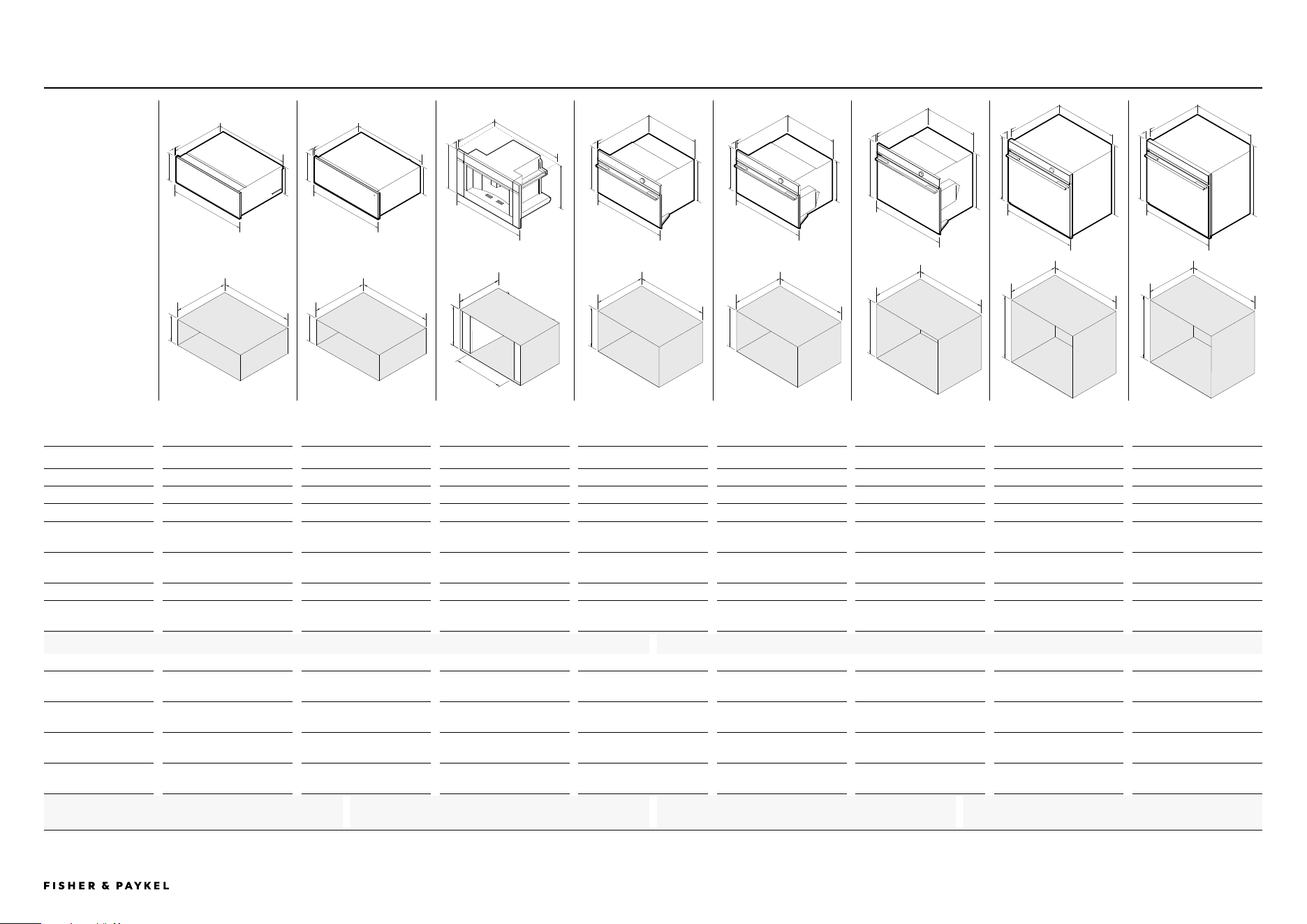
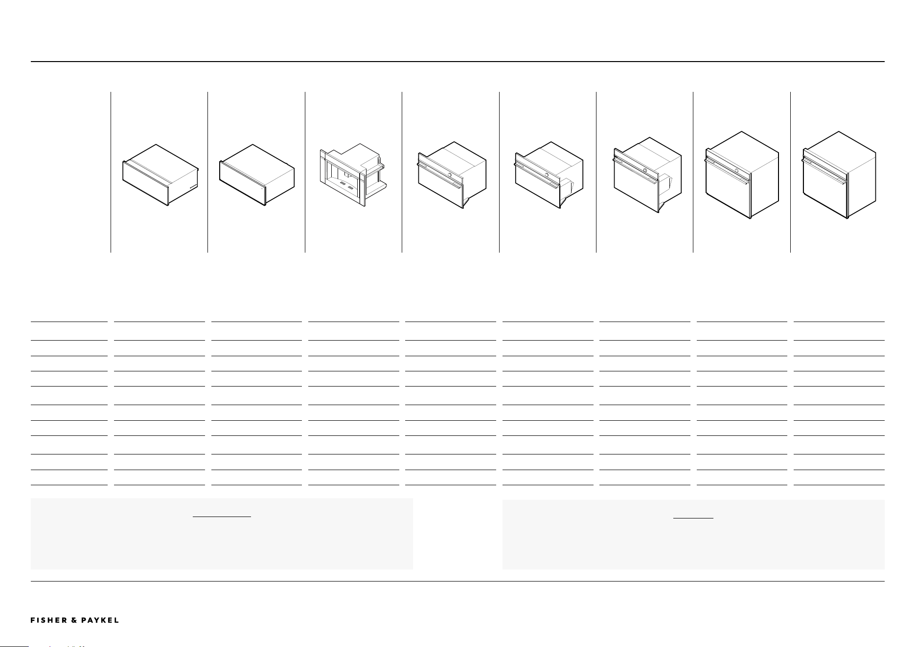
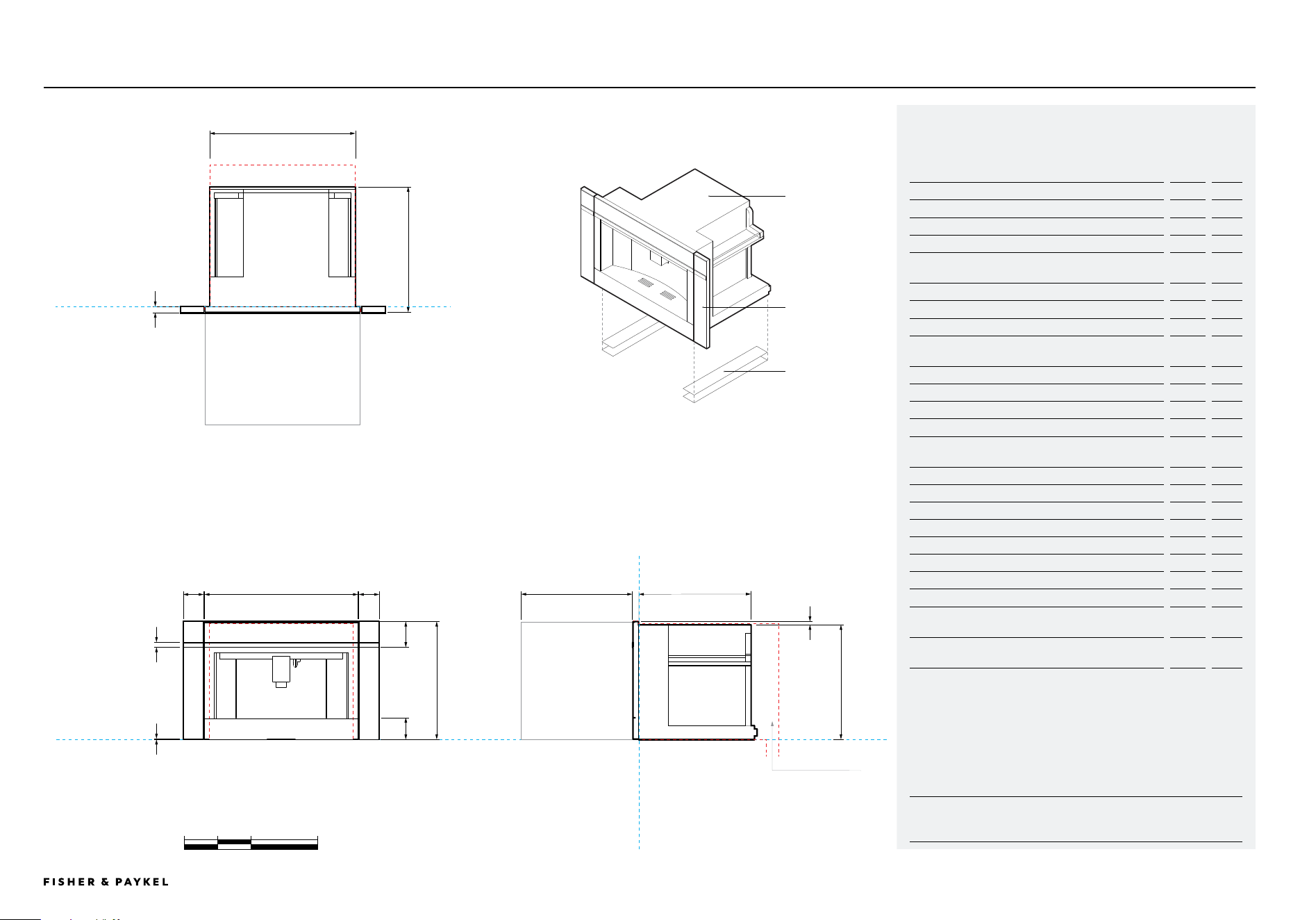
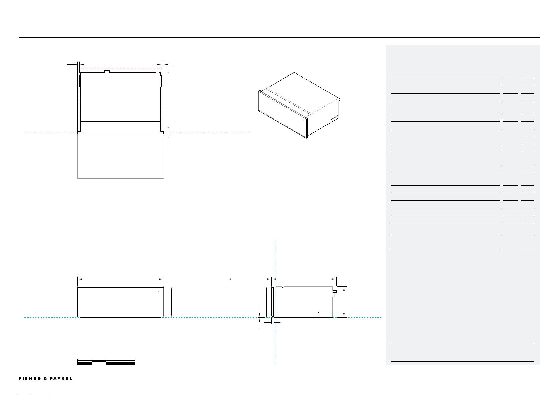
SPECIFICATION GUIDE | DIMENSIONS
PRODUCT
DIMENSIONS
CAVITY
DIMENSIONS
A
B
e
f
VACUUM SEAL DRAWER
VB30SDB1-SET
WARMING DRAWER
WB30SDB1-SET
BUILT-IN COFFEE MAKER
EB24DSXBB1
Trim Kit TK7630NDB2
CONVECTION SPEED OVEN
OM30NDTDB1
COMBINATION STEAM OVEN
OS30NDTDB1
COMBINATION STEAM OVEN
OS30SDTDB1
OVEN
OB30SDPTDB1
OVEN
OB30SDPTB1
PRODUCT DIMENSIONS
A Overall height 10 11/16" (271mm) 10 11/16" (271mm) 18" (458mm)** 18" (458mm) 18" (458mm) 23 9/16" (598mm) 27 3/16" (690mm) 27 3/16" (690mm)
B Overall width 29 15/16" (760mm) 29 15/16" (760mm) 29 15/16" (760mm)** 29 15/16" (760mm) 29 15/16" (760mm) 29 15/16" (760mm) 29 15/16" (760mm) 29 15/16" (760mm)
C Chassis height 10 11/16" (271mm) 10 11/16" (271mm) 17 1/2" (445mm) 17 1/8" (435mm) 17 1/8" (435mm) 22 5/8" (575mm) 26 9/16" (674mm) 26 9/16" (674mm)
D Chassis width
28 7/16" (722mm)
Includes side brackets
27 3/4" (704mm) 22 1/16" (560mm) 28 3/8" (720mm) 28 3/8" (720mm) 28 3/8" (720mm) 28 3/8" (720mm) 28 3/8" (720mm)
E Chassis depth
21 11/16" (551mm)
Including power plug
21 9/16" (547mm)
Including power plug
18 1/8" (460mm) 21 7/16" (545mm) 21 7/16" (545mm) 21 7/16" (545mm) 22 7/16" (569mm) 22 7/16" (569mm)
F Front panel thickness 13/16" (20mm) 13/16" (20mm) 13/16" (20mm)** 13/16" (20mm) 13/16" (20mm) 13/16" (20mm) 1 9/16" (40mm) 1 9/16" (40mm)
Depth of oven door
fully open
- - -
12 5/8" (320mm)
* 12 5/8" (320mm)* 18 1/8" (460mm)* 21 11/16" (550mm)* 21 11/16" (550mm)*
CAVITY DIMENSIONS- FLUSH INSTALLATION
G Minimum inside height
of cavity
10 3/4" (273mm)
* 10 3/4" (273mm)*
17 3/4" (450mm) 17 5/16" (440mm) 17 5/16" (440mm) 22 13/16" (580mm) 26 13/16" (681mm) 26 13/16" (681mm)
H Minimum inside width
of cavity
28 1/2" (724mm) 28 1/2" (724mm) 22 1/16" (560mm)*** 28 1/2" (724mm) 28 1/2" (724mm) 28 1/2" (724mm) 28 1/2" (724mm) 28 1/2" (724mm)
I Minimum inside depth
of cavity
****
22 13/16" (580mm) 22 13/16" (580mm) 22 13/16" (580mm)**
22 7/16" (570mm)
**
22 7/16" (570mm) 22 7/16" (570mm) 24 3/16" (615mm) 24 3/16" (615mm)
Recommened cabinet
width
30 1/16" (764mm) 30 1/16" (764mm) 30 1/16" (764mm) 30 1/16" (764mm) 30 1/16" (764mm) 30 1/16" (764mm) 30 1/16" (764mm) 30 1/16" (764mm)
d
c
g
h
I
A
B
e
f
d
c
g
h
I
A
B
e
f
d
c
g
h
I
A
B
e
f
d
c
g
h
I
A
B
e
f
d
c
g
h
I
A
B
e
f
d
c
g
h
I
A
B
e
f
d
c
g
h
I
A
B
e
f
d
c
g
h
I
Dimensions - ALL MODELS
ALL MODELS
* Measured from front of control panel
*Drawers can fully support 30inch Fisher & Paykel wall
oven, without adding shelf in between
**Requires ventilation at the rear of the cavity
***Cabinetry requires additional vertical sidewalls to
secure the product
** Measurements with trim kit
****Measured from front of control panel
<< CONTENTS
The models shown in this Planning Guide may not be available in all markets and are subject to change at any time. Product specifications may vary from those shown. This Planning Guide should not be used as installation guidance for any
product. Further information is required to safely and correctly install the products featured here. Specific installation guidance will be available on our website fisherpaykel.com
© FISHER & PAYKEL LIMITED 2024 PAGE 1690003336E PLANNING GUIDE COOKING - VERSION E - SEPTEMBER 2024
For more infomation on cord length, water supply and electrical requirements, refer to the
'Services' section of this Planning Guide.
SERVICES
VACUUM SEAL DRAWER
VB30SDB1-SET
WARMING DRAWER
WB30SDB1-SET
BUILT-IN COFFEE MAKER
EB24DSXBB1
Trim Kit TK7630NDB2
CONVECTION SPEED OVEN
OM30NDTDB1
COMBINATION STEAM OVEN
OS30NDTDB1
COMBINATION STEAM OVEN
OS30SDTDB1
OVEN
OB30SDPTDB1
OVEN
OB30SDPTB1
POWER REQUIREMENTS
Supply 120 V, 60 Hz 120 V, 60 Hz 120 V, 60 Hz 208 V or 240 V, 60 Hz 208 V or 240 V, 60 Hz 208 V or 240 V, 60 Hz 208 V or 240 V, 60 Hz 208 V or 240 V, 60 Hz
Service 10 A 10 A 10 A 20 A 20 A 20 A 20 A 20 A
Connection Flex cord 70 7/8"(1800mm) Flex cord 70 7/8"(1800mm) Flex cord 66 15/16"(1700mm) Hard wired 59 1/16"(1500mm) Hard wired 78 3/4"(2000mm) Hard wired 78 3/4"(2000mm) Hard wired 78 3/4"(2000mm) Hard wired 78 3/4"(2000mm)
WEIGHT
Packaged 148lb (67kg) 66lb (30kg) EB24DSXBB1 72lb (33kg) 121lb (55kg) 121lb (55kg) 152lb (69kg) 243lb (110kg) 243lb (110kg)
Unpackaged 121lb (55kg) 55lb (25kg) EB24DSXBB1 53lb (24kg) 101lb (46kg) 101lb (46kg) 119lb (54kg) 165lb (75kg) 165lb (75kg)
CAPACITY
Total oven - - 1.7cu ft (49L) 1.9cu ft (55L) 3cu ft (85L) 4.1cu ft (115L) 4.1cu ft (115L)
Total water tank - - 84.5 fl oz (2.5L) - 47.3 fl oz (1.4L) 47.3 fl oz (1.4L) - -
SPECIFICATION GUIDE | POWER, WEIGHT AND CAPACITY
All Coffee Makers and Steam Ovens have internal water tanks which need to be filled manually.
No external water supply is required.
WATER
Power, Weight and Capacity - ALL MODELS
ALL MODELS
<< CONTENTS

© FISHER & PAYKEL LIMITED 2024 PAGE 1790003336E PLANNING GUIDE COOKING - VERSION E - SEPTEMBER 2024
DATA SHEETS
Data Sheets
© FISHER & PAYKEL LIMITED 2024 PAGE 1890003336E PLANNING GUIDE COOKING - VERSION E - SEPTEMBER 2024
IMPORTANT NOTE: Throughout this guide, dimensions may vary by ±2mm
(1/16''). Please read the Installation Guide for detailed information on
installing the product. For full installation instructions visit fisherpaykel.com
INDICATES PRODUCT DATUM -------------------------------------------
INDICATES CABINETRY CLEARANCES --------------------------------
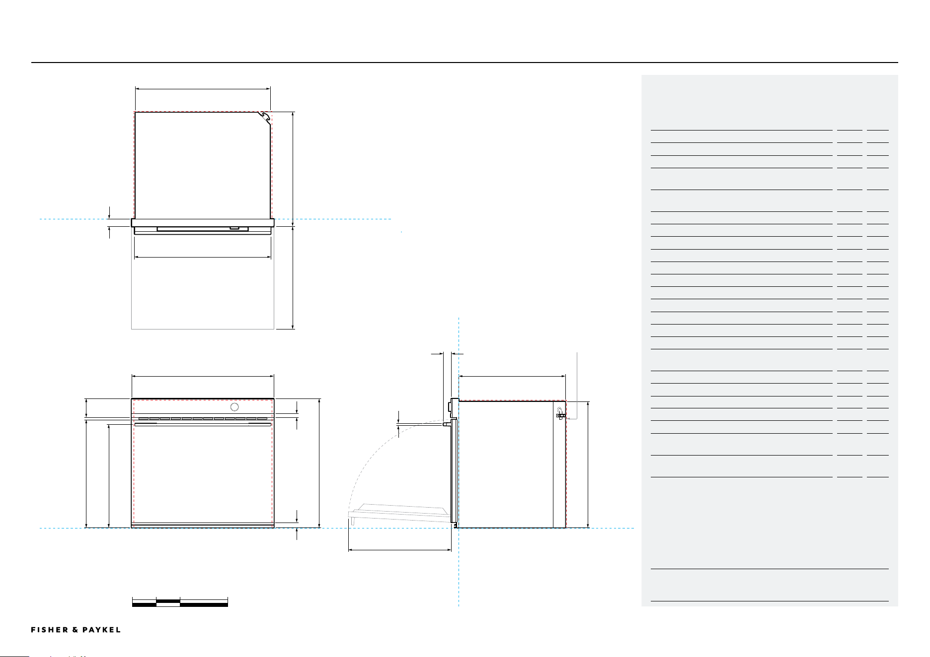
DATA SHEET | OVEN, 30"
Oven
OB30SDPTDB1 | OB30SDPTB1
g
d
c
p
m
h
j
k
i
l
o
n
p
f
DATUM: FRONT OF CHASSIS
b
29 15/16"
a
27 3/16"
e
22 7/16"
POWER
OUTLET
LOCATION
DATUM: FRONT OF CHASSIS
PLAN VIEW
FRONT VIEW PROFILE VIEW
Inches
0 5 10 20
DATUM : BOTTOM OF CHASSIS
Model no:
Oven, 30" - OB30SDPTDB1, OB30SDPTB1
Product Dimensions
in
mm
A Overall height of product
27 3/16
690
B Overall width of product
29 15/16
760
C Depth of control panel (excludes handle, front black
aluminum trim and dial)
1 9/16
40
D Depth of chassis and control panel (excludes handle,
front black aluminum trim and dial)
24
609
E Depth of chassis
22 7/16
569
F Height of chassis
26 9/16
674
G Width of chassis
28 3/8
720
H Height of control panel
3 15/16
100
I Height of black aluminum trim on control panel
3/4
20
J Height from bottom datum to top of oven door
22 3/4
578
K Height from bottom datum to centerline of handle
21 3/4
553
L Height from bottom datum to bottom of door
1 1/8
28
M Width of handle
28 5/8
727
N Depth of handle
1 5/8
42
O Thickness of handle
5/8
16
P Depth of door when open (measured from front of
door)
21 11/16
550
Minimum Clearances- Flush Installation
in
mm
Minimum inside height of cavity
26 13/16
681
Minimum inside width of cavity
28 1/2
724
Minimum inside depth of cavity*
24 3/16
615
Minimum clearance above oven control panel to upper
cabinetry front panel or appliance
1/16
2
Minimum clearance between bottom of oven chassis to
lower cabinetry front panel or appliance
1/16
2
*Measured from front of control panel
Note:Depending on cabinet panel thickness a rebate around control panel might be required.
Ensure a 3/16" (5mm) minimum clearance is maintained between the top of the oven chassis
and the cabinetry. Ensure the oven is not bearing any weight from cabinetry or products
installed above.
IMPORTANT NOTE: For full installation and clearance details please refer to our installation
manual.
<< CONTENTS
© FISHER & PAYKEL LIMITED 2024 PAGE 1990003336E PLANNING GUIDE COOKING - VERSION E - SEPTEMBER 2024
IMPORTANT NOTE: Throughout this guide, dimensions may vary by ±2mm
(1/16''). Please read the Installation Guide for detailed information on
installing the product. For full installation instructions visit fisherpaykel.com
INDICATES PRODUCT DATUM -------------------------------------------
INDICATES CABINETRY CLEARANCES --------------------------------
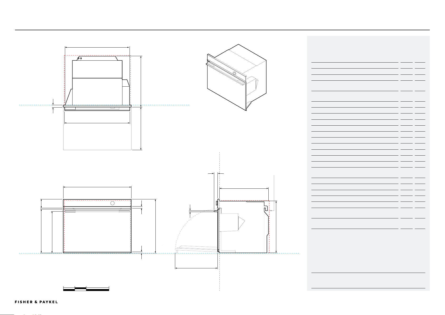
DATA SHEET | COMBINATION STEAM OVEN, 30"
Combination Steam Oven
b
29 15/16"
a
23 9/16"
e
21 7/16"
OS30SDTDB1
Model no:
Combination Steam Oven, 30" - OS30SDTDB1
Product Dimensions
in
mm
A Overall height of product
23 9/16
598
B Overall width of product
29 15/16
760
C Depth of control panel (excludes handle, front black
aluminum trim and dial)
13/16
20
D Depth of chassis and control panel (excludes handle,
front black aluminum trim and dial)
22 1/4
565
E Depth of chassis
22 7/16
545
F Height of chassis
22 5/8
575
G Width of chassis
28 3/8
720
H Height of control panel
3 15/16
100
I Height of black aluminum trim on control panel
3/4
20
J Height from bottom datum to top of oven door
19 3/16
487
K Height from bottom datum to centerline of handle
18 1/4
464
L Height from bottom datum to bottom of door
1/2
12
M Width of handle
28 5/8
727
N Depth of handle
1 5/8
42
O Thickness of handle
5/8
16
P Depth of door when open (measured from front of
door)
18 1/8
460
Minimum Clearances - Flush Installation
in
mm
Minimum inside height of cavity
22 13/16
580
Minimum inside width of cavity
28 1/2
724
Minimum inside depth of cavity*
22 7/16
570
Minimum clearance above oven control panel to upper
cabinetry front panel or appliance
1/16
2
Minimum clearance between bottom of oven chassis to
lower cabinetry front panel or appliance
1/16
2
*Measured from front of control panel
Ensure a 3/16" (5mm) minimum clearance is maintained between the top of the oven chassis
and the cabinetry. Ensure the oven is not bearing any weight from cabinetry or products
installed above.
NOTE: For full installation and clearance details please refer to our installation manual.
g
d
c
p
m
h
j
k
i
l
o
n
p
f
DATUM: FRONT OF CHASSIS
POWER
OUTLET
LOCATION
DATUM: FRONT OF CHASSIS
PLAN VIEW
FRONT VIEW PROFILE VIEW
Inches
0 5 10 20
DATUM : BOTTOM OF CHASSIS
<< CONTENTS
© FISHER & PAYKEL LIMITED 2024 PAGE 2090003336E PLANNING GUIDE COOKING - VERSION E - SEPTEMBER 2024
IMPORTANT NOTE: Throughout this guide, dimensions may vary by ±2mm
(1/16''). Please read the Installation Guide for detailed information on
installing the product. For full installation instructions visit fisherpaykel.com
INDICATES PRODUCT DATUM -------------------------------------------
INDICATES CABINETRY CLEARANCES --------------------------------
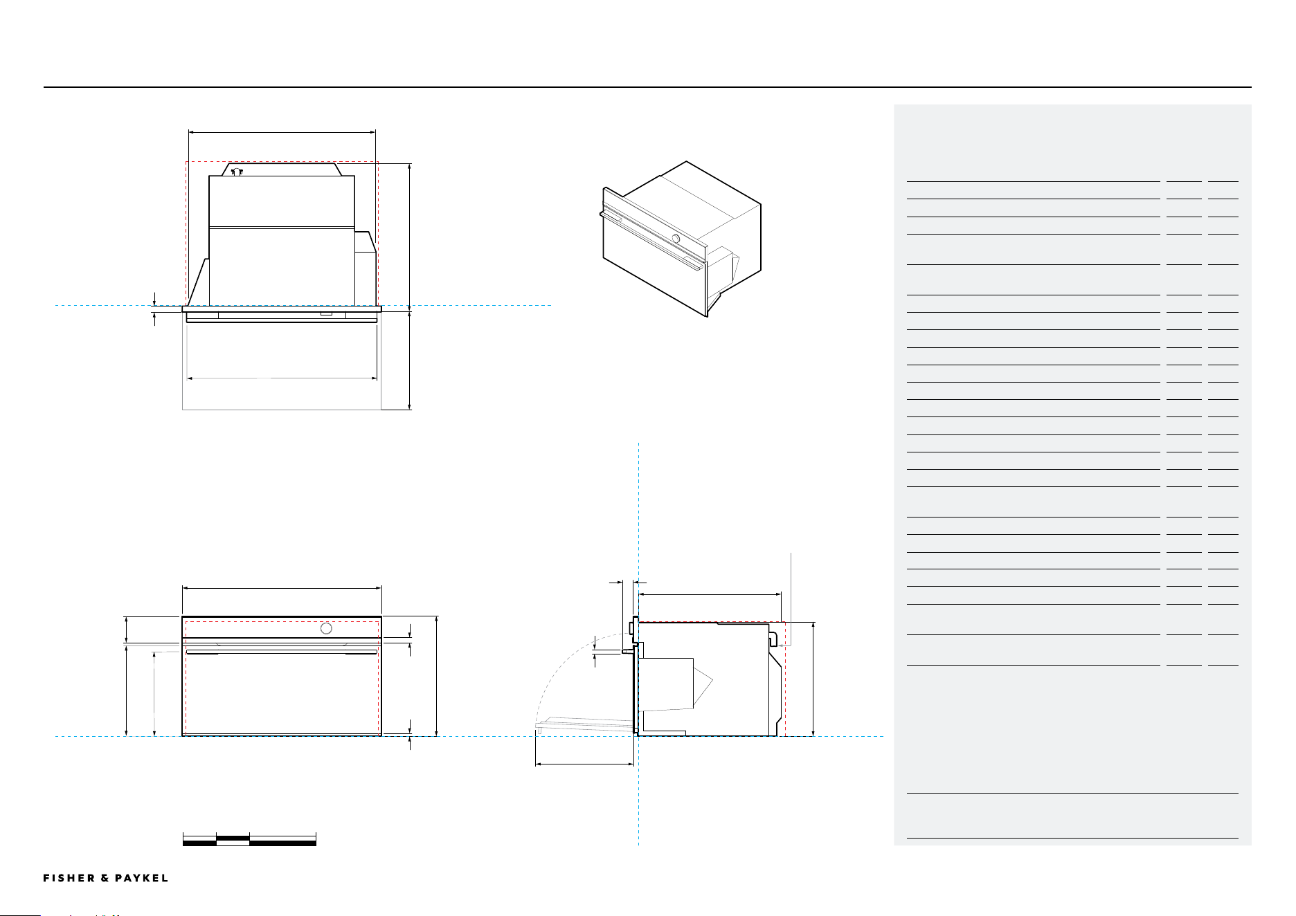
DATA SHEET | COMBINATION STEAM OVEN, 30"
Combination Steam Oven
OS30NDTDB1
b
29 15/16"
a
18"
e
21 1/16"
g
d
c
p
m
h
j
k
i
l
o
n
p
f
DATUM: FRONT OF CHASSIS
POWER
OUTLET
LOCATION
DATUM: FRONT OF CHASSIS
PLAN VIEW
FRONT VIEW PROFILE VIEW
Inches
0 5 10 20
DATUM : BOTTOM OF CHASSIS
Model no:
Combination Steam Oven, 30" - OS30NDTDB1
Product Dimensions
in
mm
A Overall height of product
18
458
B Overall width of product
29 15/16
760
C Depth of control panel (excludes handle, front black
aluminum trim and dial)
13/16
20
D Depth of chassis and control panel (excludes handle,
front black aluminum trim and dial)
22 1/4
565
E Depth of chassis
21 1/16
545
F Height of chassis
17 1/8
435
G Width of chassis
28 3/8
720
H Height of control panel
3 15/16
100
I Height of black aluminum trim on control panel
13/16
20
J Height from bottom datum to top of oven door
13 11/16
347
K Height from bottom datum to centerline of handle
12 3/4
324
L Height from bottom datum to bottom of door
1/2
12
M Width of handle
28 5/8
727
N Depth of handle
1 5/8
42
O Thickness of handle
5/8
16
P Depth of door when open (measured from front of
door)
12 5/8
320
Minimum Clearances - Flush Installation
in
mm
Minimum inside height of cavity
17 5/16
440
Minimum inside width of cavity
28 1/2
724
Minimum inside depth of cavity*
22 7/16
570
Minimum clearance above oven control panel to upper
cabinetry front panel or appliance
1/16
2
Minimum clearance between bottom of oven chassis to
lower cabinetry front panel or appliance
1/16
2
*Measured from front of control panel
Ensure a 3/16" (5mm) minimum clearance is maintained between the top of the oven chassis
and the cabinetry. Ensure the oven is not bearing any weight from cabinetry or products
installed above.
NOTE: For full installation and clearance details please refer to our installation manual.
<< CONTENTS
© FISHER & PAYKEL LIMITED 2024 PAGE 2190003336E PLANNING GUIDE COOKING - VERSION E - SEPTEMBER 2024
IMPORTANT NOTE: Throughout this guide, dimensions may vary by ±2mm
(1/16''). Please read the Installation Guide for detailed information on
installing the product. For full installation instructions visit fisherpaykel.com
INDICATES PRODUCT DATUM -------------------------------------------
INDICATES CABINETRY CLEARANCES --------------------------------
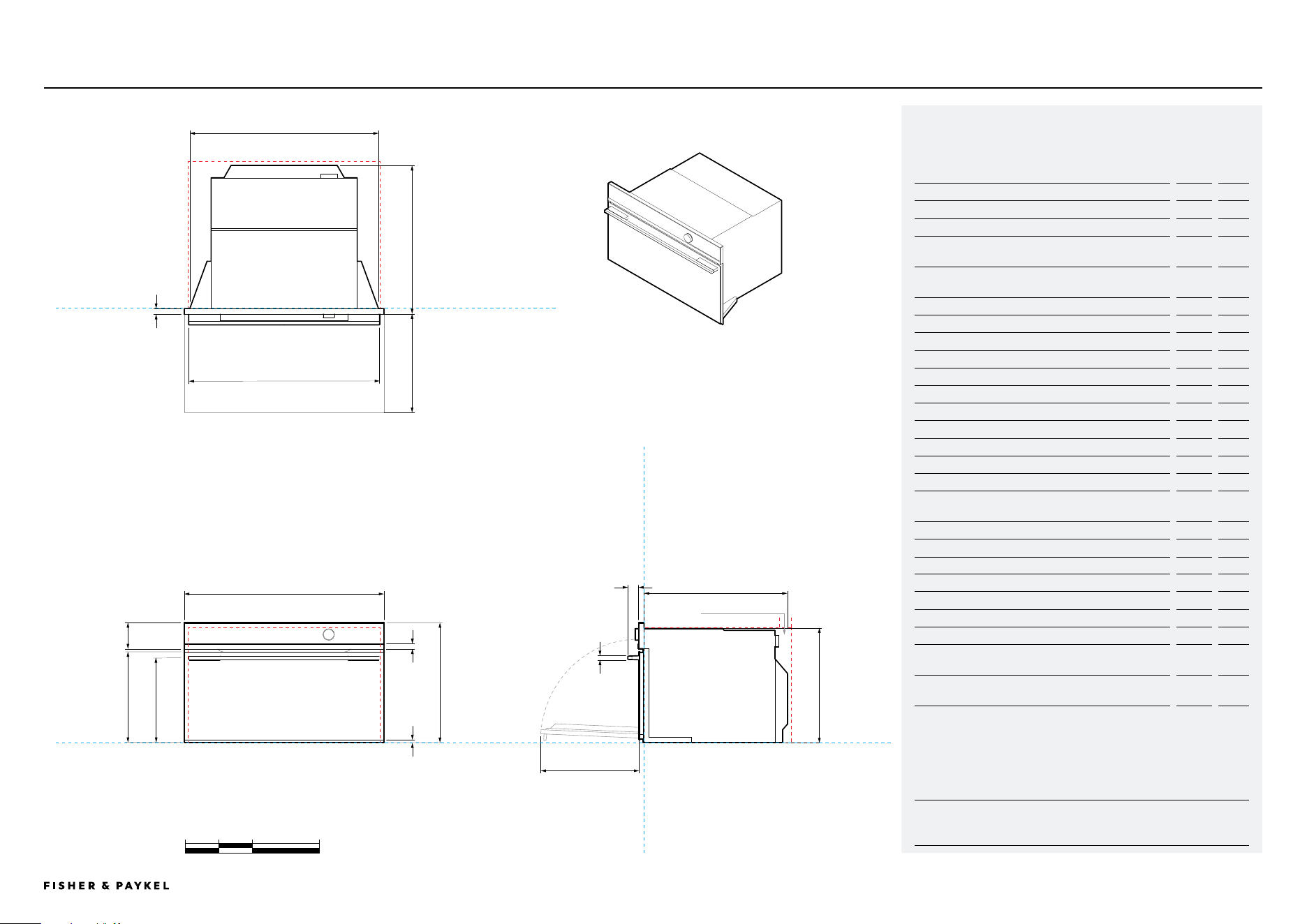
Convection Speed Oven
b
29 15/16"
a
18"
e
21 1/16"
g
d
c
p
m
h
j
k
i
l
o
p
f
DATUM: FRONT OF CHASSIS
VENTILATION
DATUM: FRONT OF CHASSIS
PLAN VIEW
FRONT VIEW PROFILE VIEW
Inches
0 5 10 20
DATUM : BOTTOM OF CHASSIS
Model no:
Convection Speed Oven, 30" - OM30NDTDB1
Product Dimensions
in
mm
A Overall height of product
18
458
B Overall width of product
29 15/16
760
C Depth of control panel (excludes handle, front black
aluminum trim and dial)
13/16
20
D Depth of chassis and control panel (excludes handle,
front black aluminum trim and dial)
22 1/4
565
E Depth of chassis
21 1/16
545
F Height of chassis
17 1/8
435
G Width of chassis
28 3/8
720
H Height of control panel
3 15/16
100
I Height of black aluminum trim on control panel
13/16
20
J Height from bottom datum to top of oven door
13 11/16
347
K Height from bottom datum to centerline of handle
12 3/4
324
L Height from bottom datum to bottom of door
1/2
12
M Width of handle
28 5/8
727
N Depth of handle
1 5/8
42
O Thickness of handle
5/8
16
P Depth of door when open (measured from front of
door)
12 5/8
320
Minimum Clearances - Flush Installation
in
mm
Minimum inside height of cavity
17 5/16
440
Minimum inside width of cavity
28 1/2
724
Minimum inside depth of cavity*
22 7/16
570
Rear ventilation depth**
2
50
Rear ventilation width**
22 1/16
560
Minimum clearance above oven control panel to upper
cabinetry front panel or appliance
1/16
2
Minimum clearance between bottom of oven chassis to
lower cabinetry front panel or appliance
1/16
2
*Measured from front of control panel
**Rear ventilation totalling 43.4in
2
(280cm
2
) is required. The air vent must be located at the rear
of cabinet, it can be positioned at the base, sides, back or top of the cavity.
NOTE: For full installation and clearance details please refer to our installation manual.
n
DATA SHEET | CONVECTION SPEED OVEN, 30" OM30NDTDB1
<< CONTENTS
© FISHER & PAYKEL LIMITED 2024 PAGE 2290003336E PLANNING GUIDE COOKING - VERSION E - SEPTEMBER 2024
IMPORTANT NOTE: Throughout this guide, dimensions may vary by ±2mm
(1/16''). Please read the Installation Guide for detailed information on
installing the product. For full installation instructions visit fisherpaykel.com
INDICATES PRODUCT DATUM -------------------------------------------
INDICATES CABINETRY CLEARANCES --------------------------------
EB24DSXBB1 | TK7630NDB2 DATA SHEET | BUILT-IN COFFEE MAKER WITH TRIM KIT, 30"
Built-in Coee Maker with Trim Kit
f
c
j
i
h
k
n
m
d
a
18"
b
23 1/2"
G
18 1/8"
VENTILATION
SPACERS,
OPTIONAL.
SUPPLIED WITH
COFFEE MAKER
e
DATUM: FRONT
OF CHASSIS
DATUM: FRONT OF CHASSIS
PLAN VIEW
Inches
0 5 10 20
Model no:
Built-in Coffee Maker, 24" - EB24DSXBB1
Trim Kit, 30" - TK7630NDB2
Product Dimensions
in
mm
A Overall height of built-in coffee maker and trim kit
18
458
B Overall width of built-in coffee maker
23 1/2
596
C Overall width of trim kit
3 1/9
79
D Overall depth of built-in coffee maker and trim kit
(excludes front metal trim)
18 7/8
480
E Height of chassis of built-in coffee maker
17 1/2
445
F Width of chassis of built-in coffee maker
22 1/16
560
G Depth of chassis of built-in coffee maker
18 1/8
460
H Depth of coffee maker front frame and control panel
(excludes front metal trim)
13/16
20
I Height of control panel
3 15/16
100
J Height of metal cap on control panel
13/16
20
K Height of horizontal lower section from bottom datum
3 3/8
85
L Stepdown from control panel to chassis
1/2
13
M Extent built-in coffee maker pulls out (measured from
glass front)
17 1/8
435
N Height from bottom datum to lower edge of glass
1/16
2
Minimum Clearances - Flush Installation
in
mm
Minimum inside height of cavity
17 3/4
450
Minimum inside width of cavity
22 1/16
560
Minimum inside depth of cavity*
22 13/16
580
Rear ventilation depth**
2
50
Rear ventilation width**
22 1/16
560
Minimum clearance above Trim Kit to upper cabinetry front
panel or appliance
1/16
2
Minimum clearance between bottom of Trim Kit to lower
cabinetry front panel or appliance
1/16
2
*Measured from front of control panel
**Rear ventilation totalling 43.4in2 (280cm2) is required. The air vent must be located at the
rear of cabinet, it can be positioned at the base, sides, back or top of the cavity.
IMPORTANT NOTE: For full installation and clearance details please refer to our installation
manual.
DATUM:
BOTTOM OF
CHASSIS
TK7630NDB2
TRIM KIT
EB24DSXBB1
BUILT-IN COFFEE
MAKER
c
FRONT VIEW PROFILE VIEW
20 7/8"
l
<< CONTENTS

© FISHER & PAYKEL LIMITED 2024 PAGE 2390003336E PLANNING GUIDE COOKING - VERSION E - SEPTEMBER 2024
IMPORTANT NOTE: Throughout this guide, dimensions may vary by ±2mm
(1/16''). Please read the Installation Guide for detailed information on
installing the product. For full installation instructions visit fisherpaykel.com
INDICATES PRODUCT DATUM -------------------------------------------
INDICATES CABINETRY CLEARANCES --------------------------------
WB30SDB1-SETDATA SHEET | WARMING DRAWER, 30"
Warming Drawer
b
29 15/16"
a
10 11/16"
c
22 5/16"
e
h
i
f
g
DATUM: FRONT OF CHASSIS
DATUM: FRONT OF CHASSIS
PLAN VIEW
FRONT VIEW PROFILE VIEW
Inches
0 5 10 20
DATUM : BOTTOM OF CHASSIS
f
k
jj
d
Model no:
Warming Drawer, 30" - WB30SDB1-SET
Product Dimensions
in
mm
A Overall height of product
10 11/16
271
B Overall width of product
29 15/16
760
C Overall depth (incl. front panel & power plug, excludes
stainless cap)
22 5/16
567
D Height of chassis
10 11/16
271
E Width of chassis
27 3/4
704
F Height of drawer front panel
10 1/2
267
G Height from bottom of chassis to bottom of front panel
1/16
2
H Depth of chassis (includes power plug)
21 9/16
547
I Depth of drawer front panel and flange (excludes
stainless cap)
13/16
20
J Distance from side of chassis to side of drawer front
1 1/16
27
K Depth of open drawer (measured from front of drawer
panel)
16 3/4
425
Minimum Clearances - Flush Installation
in
mm
Minimum inside height of cavity
10 3/4
273
Minimum inside width of cavity
28 1/2
724
Minimum inside depth of cavity*
22 13/16
580
Minimum clearance above drawer front panel to upper
cabinetry front panel or appliance**
5/32
4
Minimum clearance between bottom of drawer chassis to
lower cabinetry front panel or appliance
1/16
2
*Measured from front of drawer panel
*Achieve a smaller gap between drawer front panel to upper cabinetry front panel by dropping
cabinetry front panel down
NOTE: For full installation and clearance details please refer to our installation manual.
<< CONTENTS
© FISHER & PAYKEL LIMITED 2024 PAGE 2490003336E PLANNING GUIDE COOKING - VERSION E - SEPTEMBER 2024
IMPORTANT NOTE: Throughout this guide, dimensions may vary by ±2mm
(1/16''). Please read the Installation Guide for detailed information on
installing the product. For full installation instructions visit fisherpaykel.com
INDICATES PRODUCT DATUM -------------------------------------------
INDICATES CABINETRY CLEARANCES --------------------------------
DATA SHEET | VACUUM SEAL DRAWER, 30"
Vacuum Seal Drawer
Inches
0 5 10 20
b
29 15/16"
a
10 11/16"
c
22 5/16"
e
h
i
f
g
DATUM: FRONT OF CHASSIS
DATUM: FRONT OF CHASSIS
PLAN VIEW
FRONT VIEW PROFILE VIEW
DATUM : BOTTOM OF CHASSIS
f
k
jj
d
VB30SDB1-SET
Model no:
Vacuum Seal Drawer, 30" - VB30SDB1-SET
Product Dimensions
in
mm
A Overall height of product
10 11/16
271
B Overall width of product
29 15/16
760
C Overall depth (incl. front panel & power plug, excludes
stainless cap)
22 1/2
571
D Height of chassis
10 11/16
271
E Width of chassis
28 7/16
722
F Height of drawer front panel
10 1/2
267
G Height from bottom of chassis to bottom of front panel
1/16
2
H Depth of chassis (includes power plug)
21 9/16
551
I Depth of drawer front panel and flange (excludes
stainless cap)
13/16
20
J Distance from side of chassis to side of drawer front
3/4
19
K Depth of open drawer (measured from front of drawer
panel)
16 3/4
425
Minimum Clearances - Flush Installation
in
mm
Minimum inside height of cavity
10 3/4
273
Minimum inside width of cavity
28 1/2
724
Minimum inside depth of cavity*
22 13/16
580
Minimum clearance above drawer front panel to upper
cabinetry front panel or appliance**
5/32
4
Minimum clearance between bottom of drawer chassis to
lower cabinetry front panel or appliance
1/16
2
*Measured from front of drawer panel
**Achieve a smaller gap between drawer front panel to upper cabinetry front panel by dropping
cabinetry front panel down
NOTE: For full installation and clearance details please refer to our installation manual.
<< CONTENTS

© FISHER & PAYKEL LIMITED 2024 PAGE 2590003336E PLANNING GUIDE COOKING - VERSION E - SEPTEMBER 2024
PLANNING CONSIDERATIONS
Planning Considerations
The models shown in this Planning Guide may not be available in all markets and are subject to change at any time. Product specifications may vary from those shown. This Planning Guide should not be used as installation guidance for any
product. Further information is required to safely and correctly install the products featured here. Specific installation guidance will be available on our website fisherpaykel.com
© FISHER & PAYKEL LIMITED 2024 PAGE 2690003336E PLANNING GUIDE COOKING - VERSION E - SEPTEMBER 2024
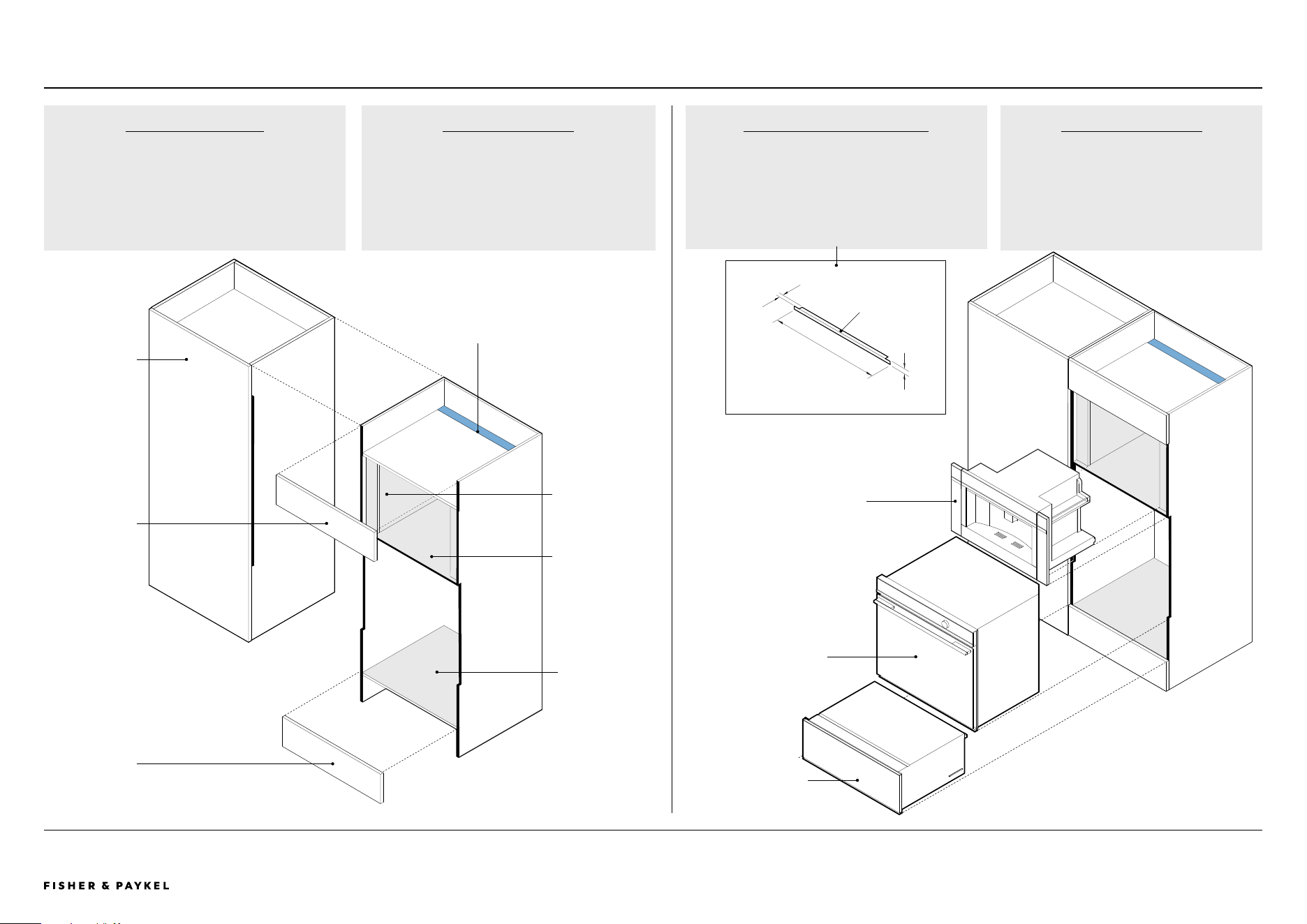
PLANNING CONSIDERATIONS | CABINETRY PREPARATION
Cabinetry Preparation - ALL MODELS
ALL MODELS
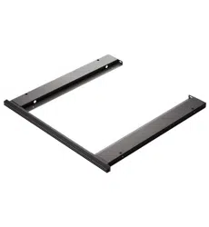
DIVIDING SHELF
If the appliance front panel is thicker than the
cabinetry front panel, adjust the dividing shelf depth
to ensure the oven sits flush with the front of the
cabinetry.
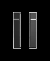
BLACK CLASHING
Black clashing is recommended on front facing edges
where products are located and on side cabinets if
cabinet is rebated.
Combination Steam Oven or
Convection Speed Oven or
Built-in Coffee Maker
Oven or Combination
Steam Oven
Warming Drawer or
Vacuum Seal Drawer
Dividing shelf
Cabinetry front
panel below
Cabinetry front
panel above
Adjacent cabinet
Supporting shelf
Ventilation gap
LEVEL CABINETRY
Check the shelves are level and the side panels
are straight.
Vertical walls for
Built-in Coffee
Maker Trim Kit
only
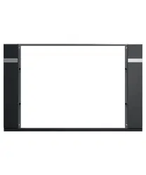
OVEN CABINETRY TRIM
If using light-colored cabinets, we recommend using
black cabinetry trim to help hide the cabinetry beneath
the front door panel of the appliance. Ensure the
trim height does not interfere with any appliances or
cabinetry below. Black cabinetry trim is included with
ovens.
Depth 1" (25mm)
Width
29 7/8" (759mm)
Height 13/16" (21mm)
Thickness
1/16" (1.5mm)
<< CONTENTS
The models shown in this Planning Guide may not be available in all markets and are subject to change at any time. Product specifications may vary from those shown. This Planning Guide should not be used as installation guidance for any
product. Further information is required to safely and correctly install the products featured here. Specific installation guidance will be available on our website fisherpaykel.com
© FISHER & PAYKEL LIMITED 2024 PAGE 2790003336E PLANNING GUIDE COOKING - VERSION E - SEPTEMBER 2024
PLANNING CONSIDERATIONS | CONFIGURATIONS, 30"
VACUUM SEAL DRAWER
VB30SDB1-SET
WARMING DRAWER
WB30SDB1-SET
BUILT-IN COFFEE MAKER
EB24DSXBB1
Trim Kit TK7630NDB2
CONVECTION SPEED OVEN
OM30NDTDB1
COMBINATION STEAM OVEN
OS30NDTDB1
COMBINATION STEAM OVEN
OS30SDTDB1
OVEN
OB30SDPTDB1
OVEN
OB30SDPTB1
DIMENSIONS
A Overall product height 10 11/16" (271mm) 10 11/16" (271mm)
18" (458mm)
**
18" (458mm) 18" (458mm) 23 9/16" (598mm) 27 3/16" (690mm) 27 3/16" (690mm)
B Minimum clearance
above
- - 1/16" (2mm) 1/16" (2mm) 1/16" (2mm) 1/16" (2mm) 1/16" (2mm) 1/16" (2mm)
C Stack height
10 11/16" (271mm)
* 10 11/16" (271mm)*
18 1/8" (460mm) 18 1/8" (460mm) 18 1/8" (460mm) 23 5/8" (600mm) 27 1/4" (692mm) 27 1/4" (692mm)
D Minimum inside height
of cavity
10 11/16" (271mm) 10 11/16" (271mm) 17 5/16" (440mm) 17 5/16" (440mm) 17 5/16" (440mm) 22 13/16" (580mm) 26 13/16" (681mm) 26 13/16" (681mm)
Configurations - ALL MODELS
MINIMUM
DIMENSION
CLEARANCES
Warming Drawers and
Vacuum Seal Drawers
can fully support a 30inch
Fisher & Paykel oven,
without adding a shelf in
between.
Ventilation air vent is
required at rear for some
products.
PRODUCT
PROFILE VIEW
Dividing shelf
location, shelf
must be above
min inside height
of cavity.
ALL MODELS
Dividing shelves are
required to support stacked
appliances and to achieve
correct clearance.
Dividing shelves must be
constructed from material
that will support the weight
of the appliances.
Ensure the oven is not
bearing any weight from
cabinetry or products
installed above.
*Drawers can fully support 30inch Fisher & Paykel wall oven, without adding shelf in between
NOTE: Stack height is overall product height with minimum clearance above appliance control panel
or front panel to upper appliance.
**Includes Built-in Coffee Maker rail height
Update measurments
STACK EXPLODED
PROFILE VIEW
C
D
BACKFRONT
Stack Height
Minimum inside height of cavity
A
B
Minimum clearance above appliance control panel to upper
appliance
B
Overall product height
+
Minimum clearance above appliance control panel or
front panel to upper appliance
=
Stacked Height
STACK HEIGHT
A
B
C
1/16"
<< CONTENTS
The models shown in this Planning Guide may not be available in all markets and are subject to change at any time. Product specifications may vary from those shown. This Planning Guide should not be used as installation guidance for any
product. Further information is required to safely and correctly install the products featured here. Specific installation guidance will be available on our website fisherpaykel.com
© FISHER & PAYKEL LIMITED 2024 PAGE 2890003336E PLANNING GUIDE COOKING - VERSION E - SEPTEMBER 2024
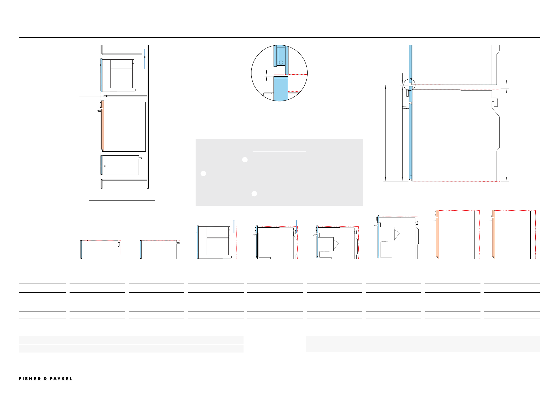
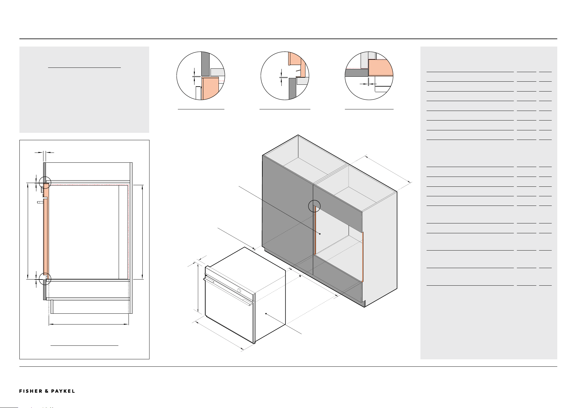
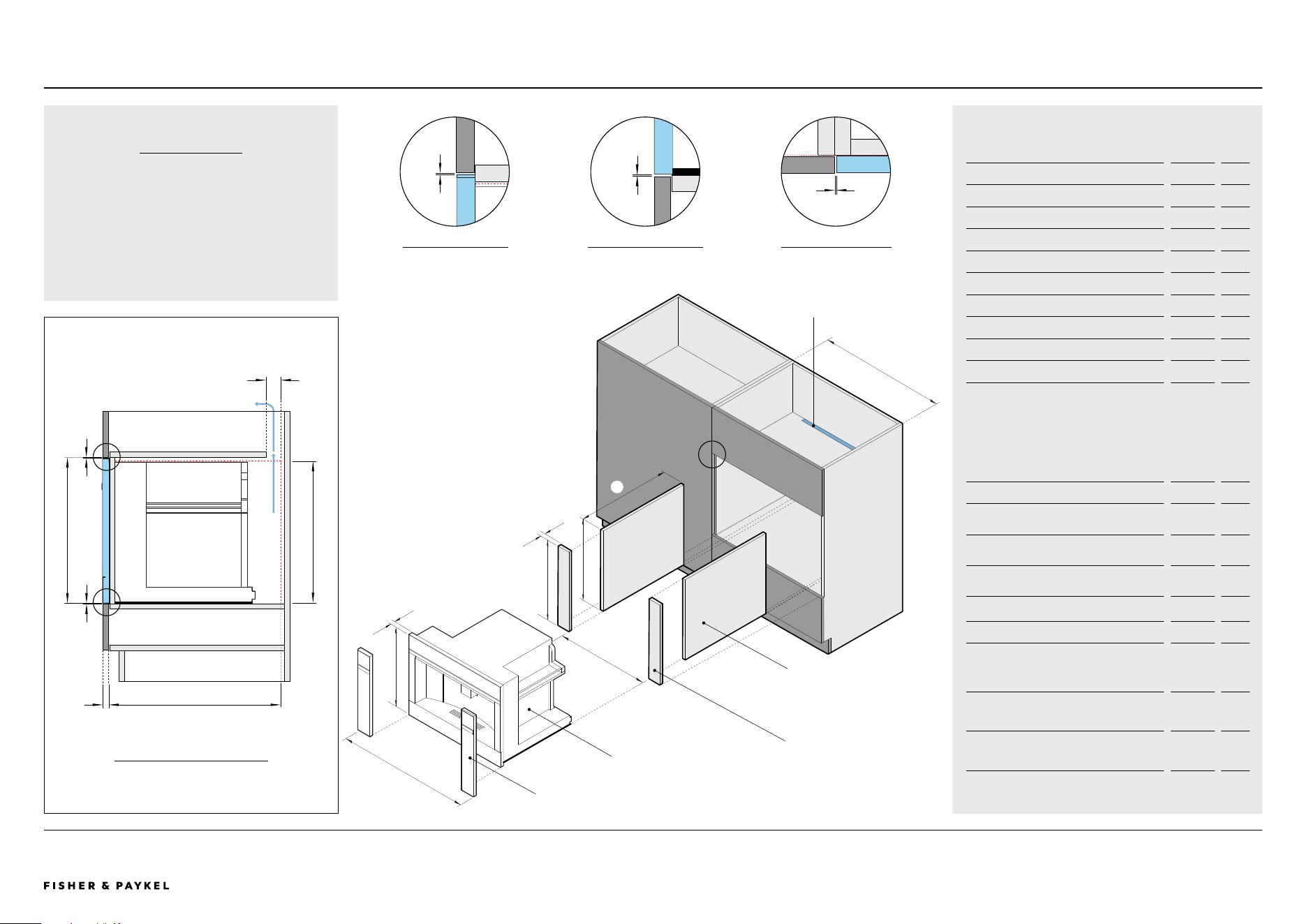
PLANNING CONSIDERATIONS | OVEN, 30"
Model no:
Oven, 30" - OB30SDPTDB1, OB30SDPTB1
Cabinetry Dimensions - Flush Installation
inch
mm
A Overall cabinet height*
27 1/4
692
B Overall cabinet width - single installation
30 1/16
764
C Minimum inside width of cavity
28 1/2
724
D Minimum inside height of cavity
26 13/16
681
E Minimum inside depth of cavity
22 5/8
575
F Thickness of cabinetry front panel** 5/8-13/16 16-20
*Overall cabinet height is overall product height with minimum clearance above
oven control panel to upper cabinetry front panel.
**Cabinetry shown in drawings 3/4" (19mm) panels.
Note: Oven requires 1/16" (2mm) spacers for screws (supplied x 2).
Product Dimensions inch mm
G Overall height of product
27 3/16
690
H Overall width of product
29 15/16
760
I Thickness of oven control panel*
1 9/16
40
*If the oven control panel is thicker than 3/4" (20mm), adjust the panel above
and below to ensure the oven sits flush with the front of the cabinetry.
Cabinetry Clearances inch mm
J Minimum clearance above oven control
panel to upper cabinetry front panel
1/16 2
K Minimum clearance between bottom of
oven chassis to lower cabinetry front panel
1/16 2
L Minimum clearance between adjacent front
panel or appliance
1/16 2
OB30SDPTDB1 | OB30SDPTB1
CLEARANCE ABOVE
PROFILE VIEW
J
1
BACKFRONT
E
F
J
K
A D
2
1
Oven
H
I
G
3
2
CLEARANCE BOTTOM
PROFILE VIEW
K
ADJACENT CABINET
PLAN VIEW
L
3
Oven
C
B
COOKTOP CLEARANCE
If installing a cooktop above the oven,
ensure adequate clearance is provided for the
cooktop as per the cooktop manufacturer’s
instructions.
2x Spacers
Sealed Cavity
CABINETRY
PROFILE VIEW
<< CONTENTS
The models shown in this Planning Guide may not be available in all markets and are subject to change at any time. Product specifications may vary from those shown. This Planning Guide should not be used as installation guidance for any
product. Further information is required to safely and correctly install the products featured here. Specific installation guidance will be available on our website fisherpaykel.com
© FISHER & PAYKEL LIMITED 2024 PAGE 2990003336E PLANNING GUIDE COOKING - VERSION E - SEPTEMBER 2024
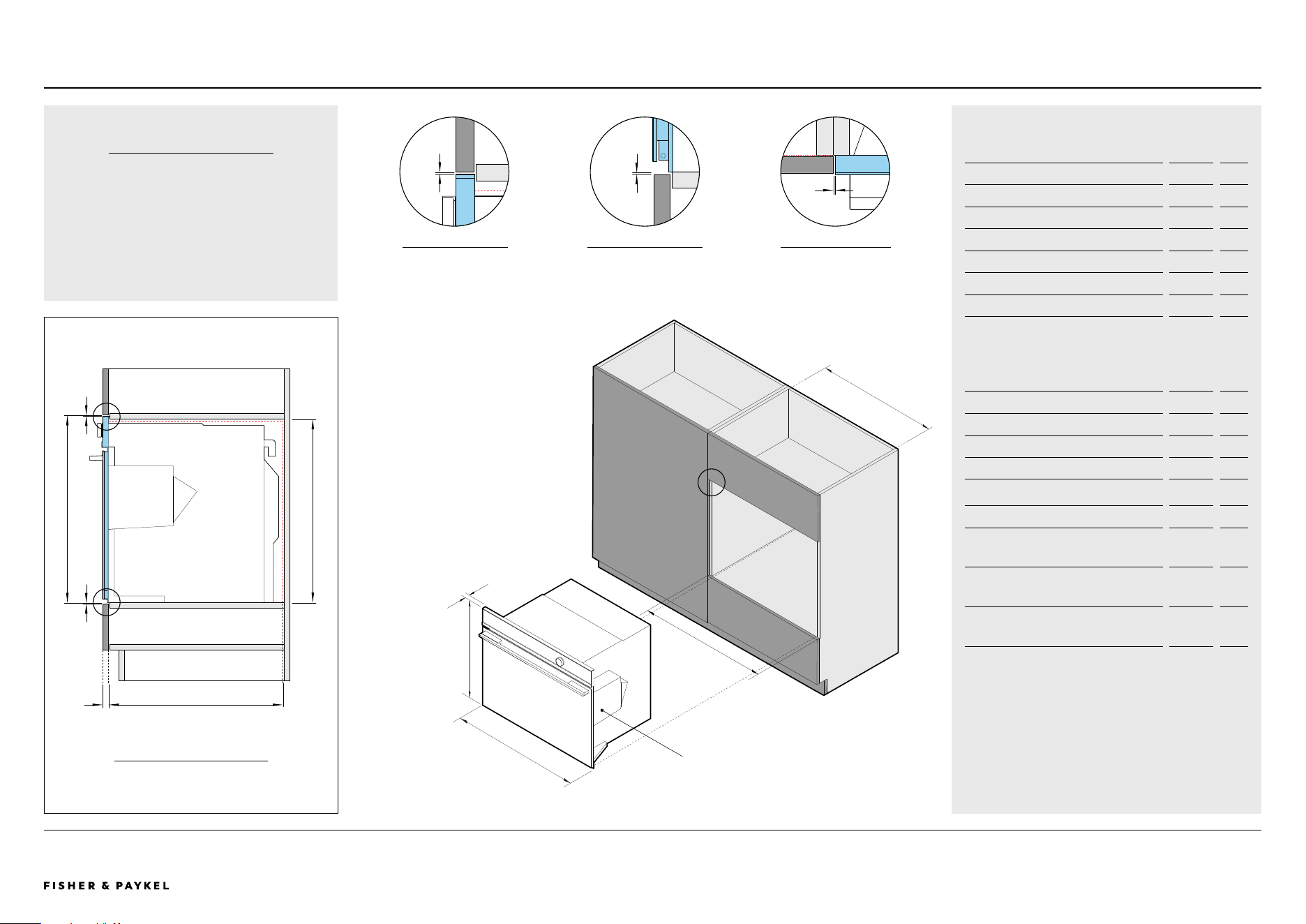
PLANNING CONSIDERATIONS | COMBINATION STEAM OVEN, 30" OS30SDTDB1
Model no:
Combination Steam Oven, 30" - OS30SDTDB1
Cabinetry Dimensions - Flush Installation
inch
mm
A Overall cabinet height*
23 5/8
600
B Overall cabinet width - single installation
30 1/16
764
C Minimum inside width of cavity
28 1/2
724
D Minimum inside height of cavity
22 13/16
580
E Minimum inside depth of cavity
21 5/8
550
F Thickness of cabinetry front panel** 5/8-13/16 16-20
*Overall cabinet height is overall product height with minimum clearance above
oven control panel to upper cabinetry front panel.
**Cabinetry shown in drawings 3/4" (19mm) panels.
Note: Concider placement of shelf above minimum inside height of cavity.
Product Dimensions inch mm
G Overall height of product
23 9/16
598
H Overall width of product
29 15/16
760
I Thickness of oven front panel
13/16
20
Cabinetry Clearances inch mm
J Minimum clearance above oven control
panel to upper cabinetry front panel
1/16 2
K Minimum clearance between bottom of
oven chassis to lower cabinetry front panel
1/16 2
L Minimum clearance between adjacent front
panel or appliance
1/16 2
J
1
BACKFRONT
E
J
K
A D
2
1
Combination Steam Oven
H
I
G
3
2
K
L
3
C
B
COOKTOP CLEARANCE
If installing a cooktop above the oven,
ensure adequate clearance is provided for the
cooktop as per the cooktop manufacturer’s
instructions.
F
Combination Steam Oven
CABINETRY
PROFILE VIEW
CLEARANCE ABOVE
PROFILE VIEW
CLEARANCE BOTTOM
PROFILE VIEW
ADJACENT CABINET
PLAN VIEW
<< CONTENTS
The models shown in this Planning Guide may not be available in all markets and are subject to change at any time. Product specifications may vary from those shown. This Planning Guide should not be used as installation guidance for any
product. Further information is required to safely and correctly install the products featured here. Specific installation guidance will be available on our website fisherpaykel.com
© FISHER & PAYKEL LIMITED 2024 PAGE 3090003336E PLANNING GUIDE COOKING - VERSION E - SEPTEMBER 2024
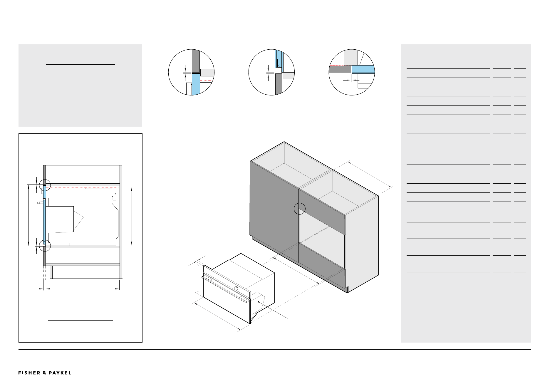
PLANNING CONSIDERATIONS | COMBINATION STEAM OVEN, 30" OS30NDTDB1
Combination Steam Oven
Model no:
Combination Steam Oven, 30" - OS30NDTDB1
Cabinetry Dimensions - Flush Installation
inch
mm
A Overall cabinet height*
18 1/8
460
B Overall cabinet width - single installation
30 1/16
764
C Minimum inside width of cavity
28 1/2
724
D Minimum inside height of cavity
17 5/16
440
E Minimum inside depth of cavity
21 5/8
550
F Thickness of cabinetry front panel** 5/8-13/16 16-20
*Overall cabinet height is overall product height with minimum clearance above
oven control panel to upper cabinetry front panel.
**Cabinetry shown in drawings 3/4" (19mm) panels.
Note: Concider placement of shelf above minimum inside height of cavity.
Product Dimensions inch mm
G Overall height of product
18
458
H Overall width of product
29 15/16
760
I Thickness of oven front panel
13/16
20
Cabinetry Clearances inch mm
J Minimum clearance above oven control
panel to upper cabinetry front panel
1/16 2
K Minimum clearance between bottom of
oven chassis to lower cabinetry front panel
1/16 2
L Minimum clearance between adjacent front
panel or appliance
1/16 2
J
1
BACKFRONT
CABINETRY
PROFILE VIEW
E
J
K
A D
2
1
Combination Steam Oven
H
I
G
3
2
K
L
3
C
B
COOKTOP CLEARANCE
If installing a cooktop above the oven,
ensure adequate clearance is provided for the
cooktop as per the cooktop manufacturer’s
instructions.
F
CLEARANCE ABOVE
PROFILE VIEW
CLEARANCE BOTTOM
PROFILE VIEW
ADJACENT CABINET
PLAN VIEW
<< CONTENTS
The models shown in this Planning Guide may not be available in all markets and are subject to change at any time. Product specifications may vary from those shown. This Planning Guide should not be used as installation guidance for any
product. Further information is required to safely and correctly install the products featured here. Specific installation guidance will be available on our website fisherpaykel.com
© FISHER & PAYKEL LIMITED 2024 PAGE 3190003336E PLANNING GUIDE COOKING - VERSION E - SEPTEMBER 2024
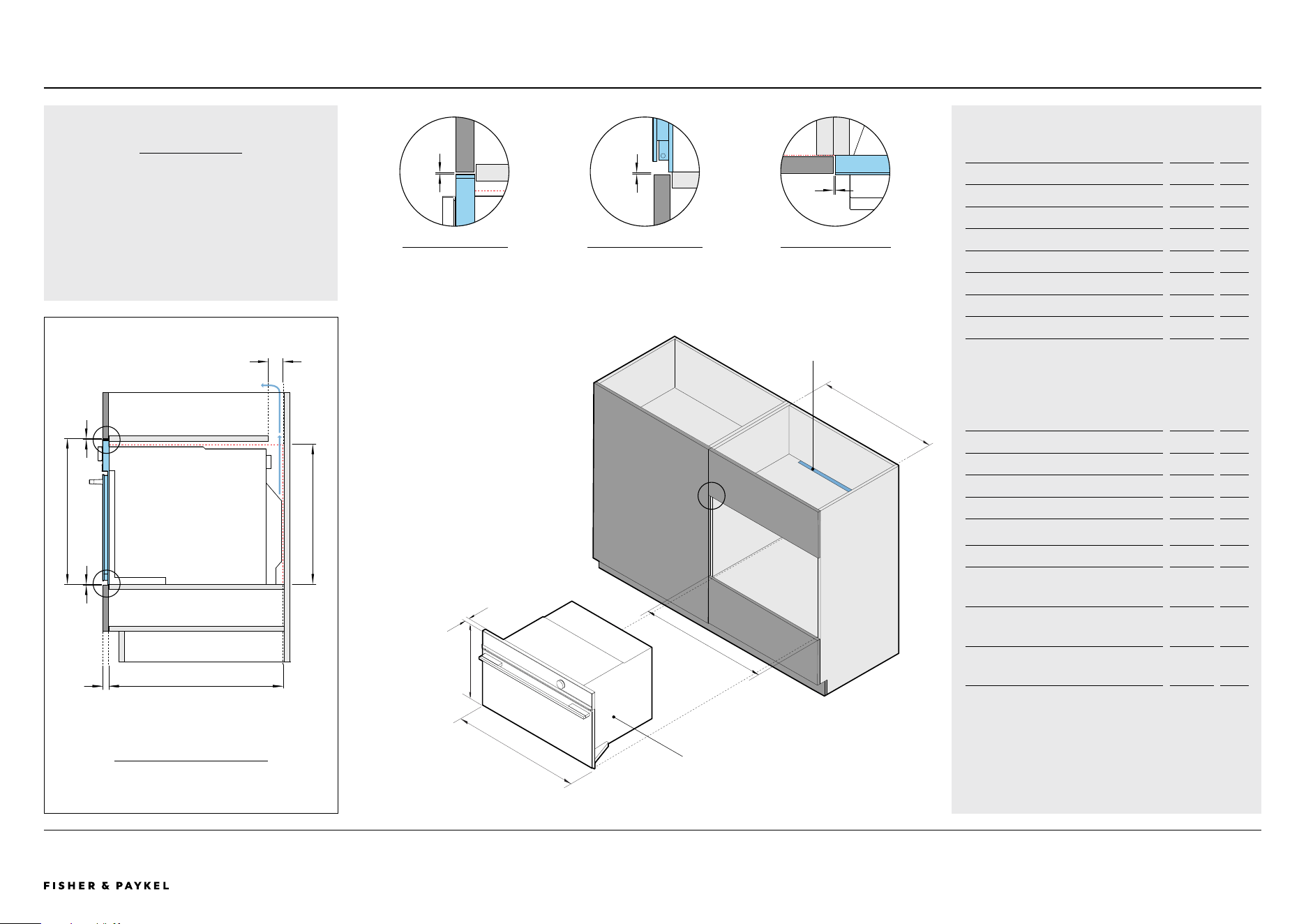
PLANNING CONSIDERATIONS | CONVECTION SPEED OVEN, 30" OM30NDTDB1
Convection Speed Oven
Model no:
Convection Speed Oven, 30" - OM30NDTDB1
Cabinetry Dimensions - Flush Installation
inch
mm
A Overall cabinet height*
18 1/8
460
B Overall cabinet width - single installation
30 1/16
764
C Minimum inside width of cavity
28 1/2
724
D Minimum inside height of cavity
17 5/16
440
E Minimum inside depth of cavity
21 5/8
550
F Thickness of cabinetry front panel** 5/8-13/16 16-20
G Ventilation gap*** 2 50
*Overall cabinet height is overall product height with minimum clearance above
oven control panel to upper cabinetry front panel.
**Cabinetry shown in drawings 3/4" (19mm) panels.
***A rear ventilation air vent totalling 43.4in
2
(280cm
2
) is required. The air vent
must be located at the rear of the cabinet, it can be positioned at the base,
sides, back or top of the cavity.
Note: Concider placement of shelf above minimum inside height of cavity.
Product Dimensions inch mm
H Overall height of product
18
458
I Overall width of product
29 15/16
760
J Thickness of oven front panel
13/16
20
Cabinetry Clearances inch mm
K Minimum clearance above oven control
panel to upper cabinetry front panel
1/16 2
L Minimum clearance between bottom of
oven chassis to lower cabinetry front panel
1/16 2
M Minimum clearance between adjacent front
panel or appliance
1/16 2
K
1
BACKFRONT
CABINETRY
PROFILE VIEW
E
J
K
A D
2
1
Convection Speed Oven
I
J
H
Ventilation gap
3
2
L
M
3
C
B
F
VENTILATION
Ventilation of 2" x 22 1/16" (50mm x 560mm)
or totalling 43.4in2 (280cm
2
) is required.
The air vent must be located at the rear of
cabinet, it can be positioned at the base, top,
sides, or back.
G
CLEARANCE ABOVE
PROFILE VIEW
CLEARANCE BOTTOM
PROFILE VIEW
ADJACENT CABINET
PLAN VIEW
<< CONTENTS
The models shown in this Planning Guide may not be available in all markets and are subject to change at any time. Product specifications may vary from those shown. This Planning Guide should not be used as installation guidance for any
product. Further information is required to safely and correctly install the products featured here. Specific installation guidance will be available on our website fisherpaykel.com
© FISHER & PAYKEL LIMITED 2024 PAGE 3290003336E PLANNING GUIDE COOKING - VERSION E - SEPTEMBER 2024
EB24DSXBB1 | TK7630NDB2PLANNING CONSIDERATIONS | BUILT-IN COFFEE MAKER WITH TRIM KIT, 30"
Built-in Coee Maker with Trim Kit
C
M
N
O
3
B
Trim Kit
1 2 3
VENTILATION
Ventilation of 2" x 22 1/16" (50mm x 560mm)
or totalling 43.4in2 (280cm
2
) is required.
The air vent must be located at the rear of
cabinet, it can be positioned at the base, top,
sides, or back.
BACKFRONT
E
M
N
A D
2
1
H
I
Built-in Coffee Maker
G
Additional sidewalls
for securing Coffee
Maker, 5/8" - 13/16"
(16-20mm) thickness
Ventilation gap
L
Additional walls
for securing
Trim Kit
Model no:
Built-in Coffee Maker, 24" - EB24DSXBB1
Trim Kit, 30" - TK7630NDB2
Cabinetry Dimensions - Flush Installation inch
mm
A Overall cabinet height with trim kit* 18 1/8
460
B Overall cabinet width - single installation
30 1/16
764
C Minimum inside width of cavity 22 1/16
560
D Minimum inside height of cavity 17 3/4
450
E Minimum inside depth of cavity 22 13/16
580
F Minimum height of additional side walls 17 3/4
450
G Minimum depth of additional side walls** 22 1/16
561
H Thickness of cabinetry front panel** 5/8-13/16 16-20
I Ventilation gap*** 2 50
*Overall cabinet height is overall product height with minimum clearance above
coffee maker control panel to upper cabinetry front panel
**Cabinetry shown in drawings 3/4" (19mm) panels.
***A rear ventilation air vent totalling 43.4in
2
(280cm
2
) is required. The air vent
must be located at the rear of the cabinet, it can be positioned at the base,
sides, back or top of the cavity.
Note: Concider placement of shelf above minimum inside height of cavity.
Product Dimensions inch mm
J Overall height of built-in coffee maker and
trim kit
18 458
K Overall width of built-in coffee maker and
trim kit
29 15/16
760
L Thickness of built-in coffee maker and trim
kit front panel
13/16
20
Cabinetry Clearances inch mm
M Minimum clearance above trim kit front
panel to upper cabinetry front panel
1/16 2
N Minimum clearance between bottom of
trim kit to lower cabinetry front panel
1/16 2
O Minimum clearance between adjacent front
panel or appliance
1/16 2
F
F
H
J
K
CABINETRY
PROFILE VIEW
CLEARANCE ABOVE
PROFILE VIEW
CLEARANCE BOTTOM
PROFILE VIEW
ADJACENT CABINET
PLAN VIEW
The models shown in this Planning Guide may not be available in all markets and are subject to change at any time. Product specifications may vary from those shown. This Planning Guide should not be used as installation guidance for any
product. Further information is required to safely and correctly install the products featured here. Specific installation guidance will be available on our website fisherpaykel.com
© FISHER & PAYKEL LIMITED 2024 PAGE 3390003336E PLANNING GUIDE COOKING - VERSION E - SEPTEMBER 2024
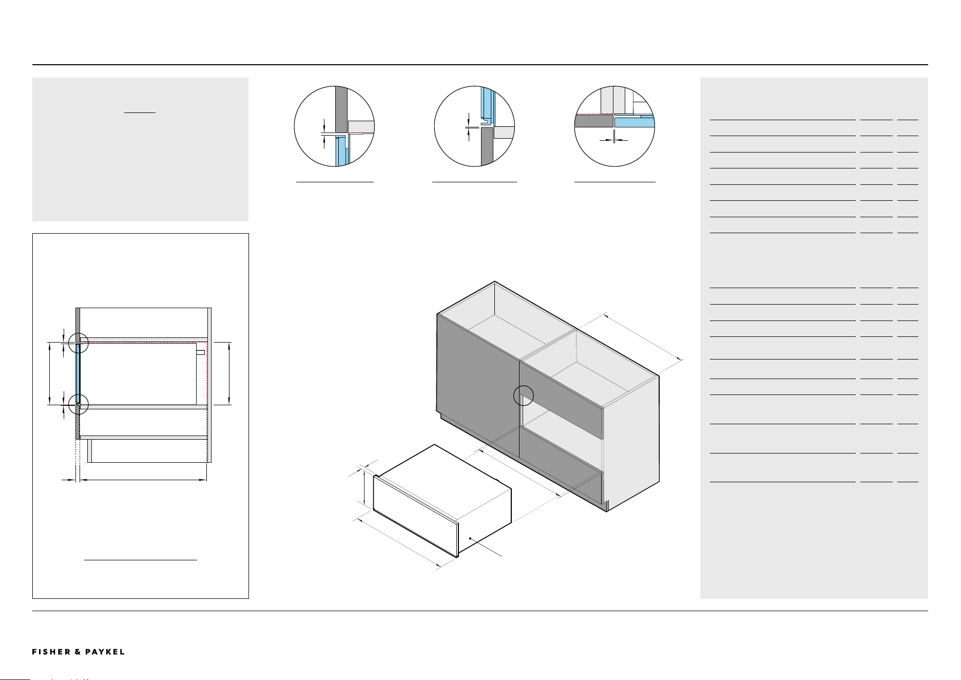
WB30SDB1-SETPLANNING CONSIDERATIONS | WARMING DRAWER, 30"
Warming Drawer
NOTE
The Warming Drawer can fully support a
30inch Fisher & Paykel oven, without adding a
shelf in between.
Model no:
Warming Drawer, 30" - WB30SDB1-SET
Cabinetry Dimensions - Flush Installation
inch
mm
A Overall cabinet height*
10 13/16
275
B Overall cabinet width - single installation
30 1/16
764
C Minimum inside width of cavity
28 1/2
724
D Minimum inside height of cavity
10 3/4
273
E Minimum inside depth of cavity
22 13/16
580
F Thickness of cabinetry front panel** 5/8-13/16 16-20
*Overall cabinet height is overall product height with minimum clearance above
drawer front panel to upper cabinetry front panel.
**Cabinetry shown in drawings 3/4" (19mm) panels.
Note: Concider placement of shelf above minimum inside height of cavity.
Product Dimensions inch mm
G Overall height of product
10 11/16
271
H Overall width of product
29 15/16
760
I Thickness of warming drawer front panel
and flange
13/16
20
Cabinetry Clearances inch mm
J Minimum clearance above drawer front
panel to upper cabinetry front panel*
5/32 4
K Minimum clearance between bottom of
drawer chassis to lower cabinetry front
panel
1/16 2
L Minimum clearance between adjacent front
panel or appliance
1/16 2
*Achieve a smaller gap between drawer front panel to upper cabinetry front
panel by dropping cabinetry front panel down
1
BACKFRONT
E
J
K
A D
2
1
Warming Drawer
3
2 3
C
B
F
J
H
I
G
K
L
CABINETRY
PROFILE VIEW
CLEARANCE ABOVE
PROFILE VIEW
CLEARANCE BOTTOM
PROFILE VIEW
ADJACENT CABINET
PLAN VIEW
<< CONTENTS
The models shown in this Planning Guide may not be available in all markets and are subject to change at any time. Product specifications may vary from those shown. This Planning Guide should not be used as installation guidance for any
product. Further information is required to safely and correctly install the products featured here. Specific installation guidance will be available on our website fisherpaykel.com
© FISHER & PAYKEL LIMITED 2024 PAGE 3490003336E PLANNING GUIDE COOKING - VERSION E - SEPTEMBER 2024
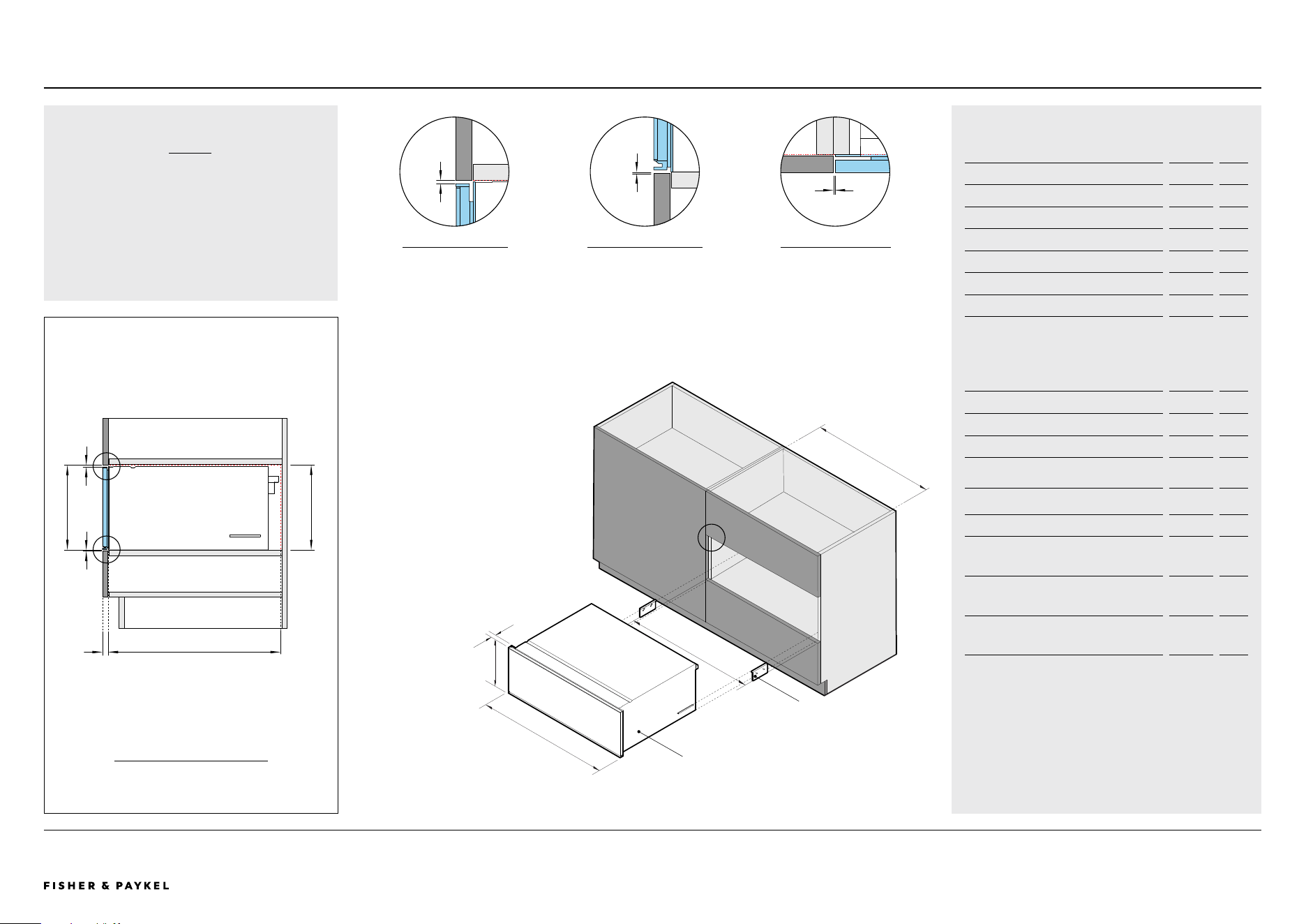
NOTE
The Vacuum Seal Drawer can fully support a
30inch Fisher & Paykel oven, without adding a
shelf in between.
VB30SDB1-SETPLANNING CONSIDERATIONS | VACUUM SEAL DRAWER, 30"
Vacuum Seal Drawer
Model no:
Vacuum Seal Drawer 30" - VB30SDB1-SET
Cabinetry Dimensions - Flush Installation
inch
mm
A Overall cabinet height*
10 13/16
275
B Overall cabinet width - single installation
30 1/16
764
C Minimum inside width of cavity
28 1/2
724
D Minimum inside height of cavity
10 3/4
273
E Minimum inside depth of cavity
22 13/16
580
F Thickness of cabinetry front panel** 5/8-13/16 16-20
*Overall cabinet height is overall product height with minimum clearance above
drawer front panel to upper cabinetry front panel.
**Cabinetry shown in drawings 3/4" (19mm) panels.
Note: Concider placement of shelf above minimum inside height of cavity.
Product Dimensions inch mm
G Overall height of product
10 11/16
271
H Overall width of product
29 15/16
760
I Thickness of vacuum seal drawer front
panel and flange
13/16
20
Cabinetry Clearances inch mm
J Minimum clearance above drawer front
panel to upper cabinetry front panel*
5/32 4
K Minimum clearance between bottom of
drawer chassis to lower cabinetry front
panel
1/16 2
L Minimum clearance between adjacent front
panel or appliance
1/16 2
*Achieve a smaller gap between drawer front panel to upper cabinetry front
panel by dropping cabinetry front panel down
J
1
BACKFRONT
E
J
K
A D
2
1
Vacuum Seal Drawer
H
I
G
2
K
L
3
C
B
F
Anti-tip Bracket
3
CABINETRY
PROFILE VIEW
CLEARANCE ABOVE
PROFILE VIEW
CLEARANCE BOTTOM
PROFILE VIEW
ADJACENT CABINET
PLAN VIEW
<< CONTENTS

© FISHER & PAYKEL LIMITED 2024 PAGE 3590003336E PLANNING GUIDE COOKING - VERSION E - SEPTEMBER 2024
SERVICES
Services
The models shown in this Planning Guide may not be available in all markets and are subject to change at any time. Product specifications may vary from those shown. This Planning Guide should not be used as installation guidance for any
product. Further information is required to safely and correctly install the products featured here. Specific installation guidance will be available on our website fisherpaykel.com
© FISHER & PAYKEL LIMITED 2024 PAGE 3690003336E PLANNING GUIDE COOKING - VERSION E - SEPTEMBER 2024
VACUUM SEAL DRAWER
VB30SDB1-SET
WARMING DRAWER
WB30SDB1-SET
BUILT-IN COFFEE MAKER
EB24DSXBB1 (TK7630NDB2)
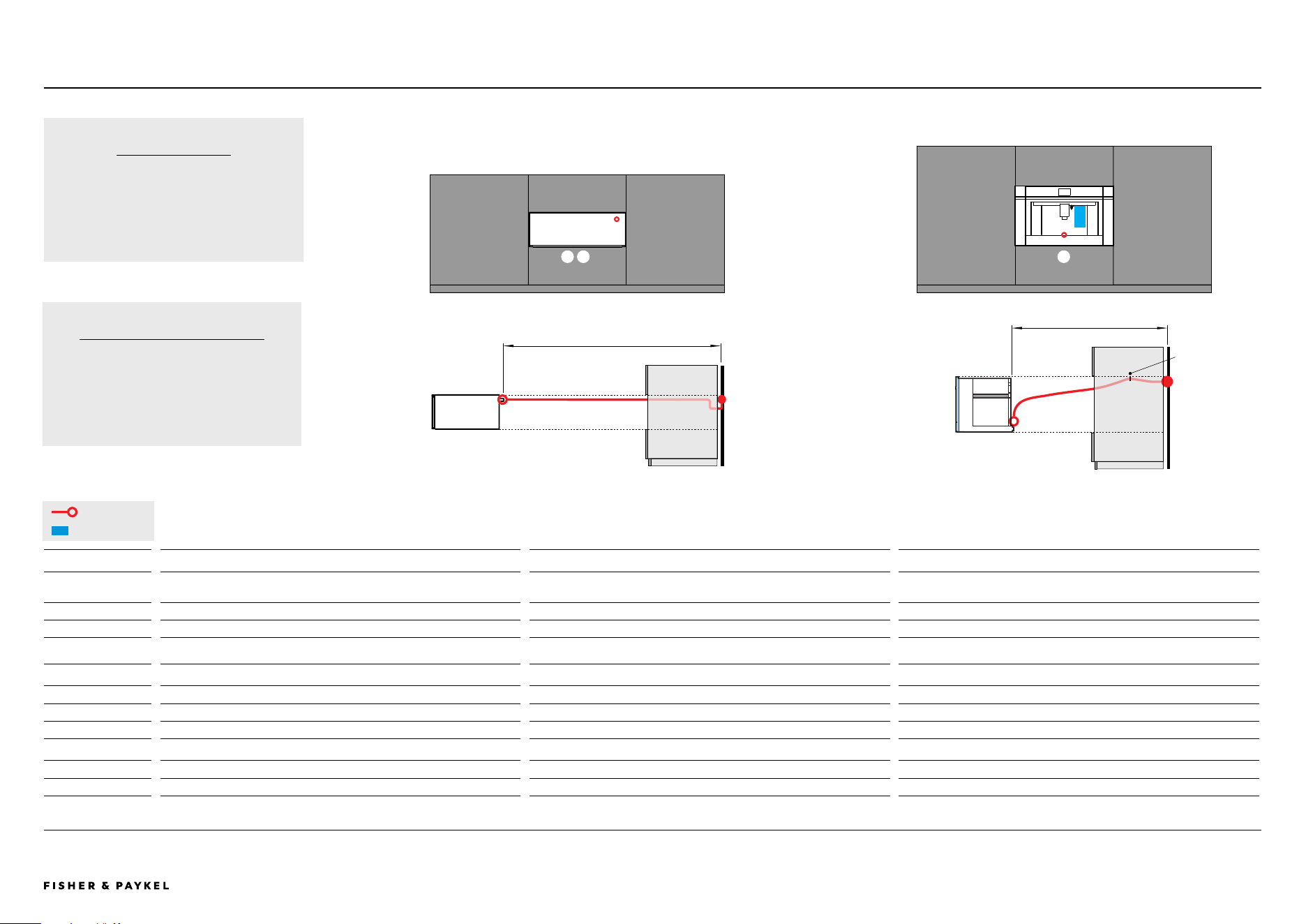
POWER CORD
Maximum power cord
length*
70 7/8" (1800mm) 70 7/8" (1800mm) 66 15/16" (1700mm)
Location Upper right Upper right Lower centered
Connection Flex cord Flex cord Flex cord
*Measured from power outlet
WATER
Total Capacity - - 84.5 fl oz (2.4L)
Location - - Water tank (internal)
ELECTRICAL
Supply 120 V, 60 Hz 120 V, 60 Hz 120 V, 60 Hz
Service 10 A 10 A 10 A
Note: Multiple product installation requires the design of power outlets according to local regulations.
Clip
provided
BUILT-IN COFFEE MAKER
The power cable must be long enough to
allow the appliance to be extracted from the
cabinet to fill the coffee bean container. Fix
the power cable with the clip.
SERVICES | POWER CORD LENGTH AND LOCATION
Power Cord Length and Location - COMPANIONS
Max 70 7/8" (1800mm)
Max 66 15/16" (1700mm)
CONNECTION
Connections may be located in an adjacent
cabinet to either side of the appliance.
Ensure power will remain accessible following
install to allow access for any future product
maintenance.
Power Cable
Water Tank
1 2 3
3
1 2
21 3
VB30SDB1-SET | WB30SDB1-SET | EB24DSXBB1 | TK7630NDB2
<< CONTENTS
The models shown in this Planning Guide may not be available in all markets and are subject to change at any time. Product specifications may vary from those shown. This Planning Guide should not be used as installation guidance for any
product. Further information is required to safely and correctly install the products featured here. Specific installation guidance will be available on our website fisherpaykel.com
© FISHER & PAYKEL LIMITED 2024 PAGE 3790003336E PLANNING GUIDE COOKING - VERSION E - SEPTEMBER 2024
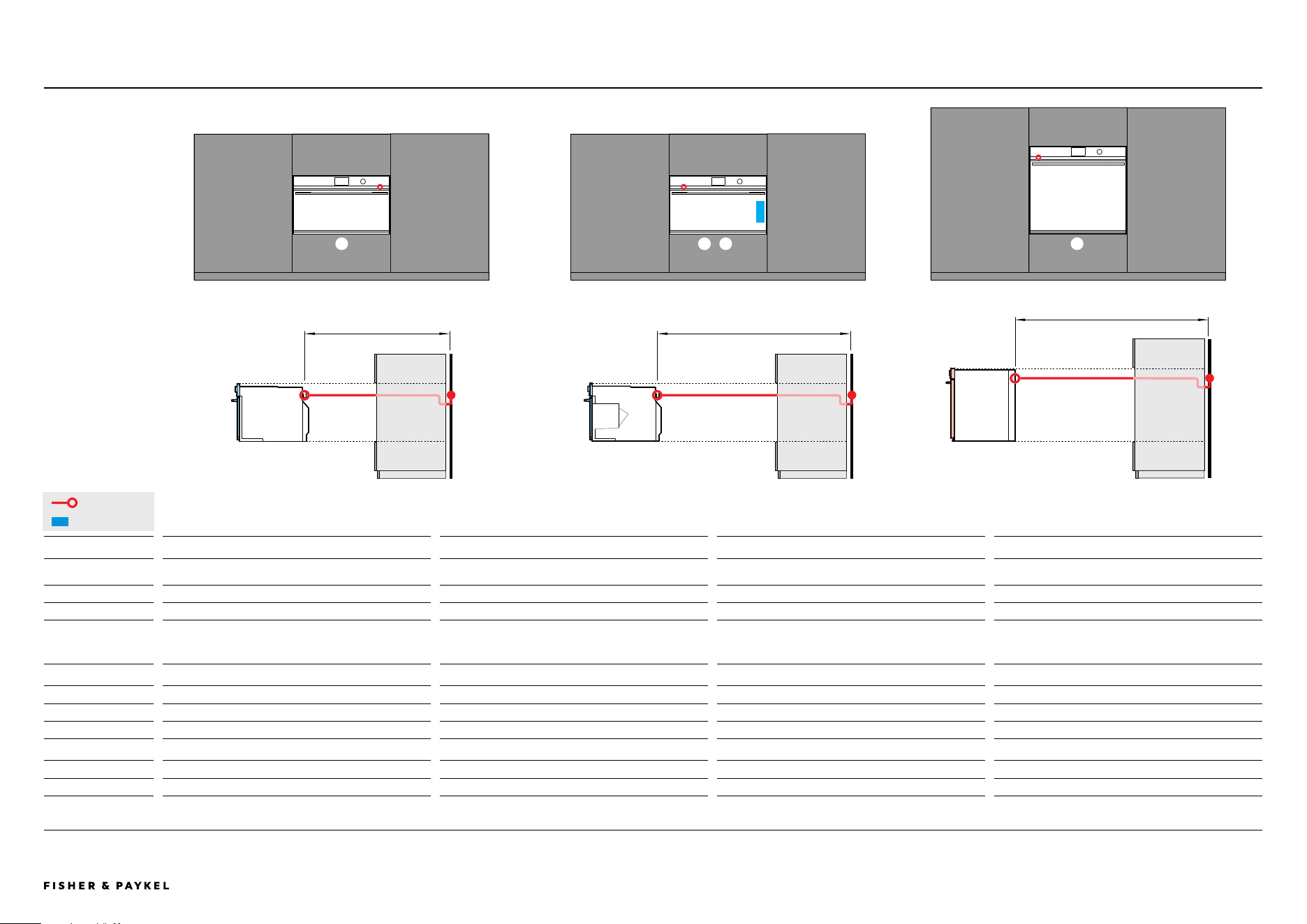
OM30NDTDB1 | OS30NDTDB1 | OS30SDTDB1 | OB30SDPTDB1 | OB30SDPTB1 SERVICES | POWER CORD LENGTH AND LOCATION
Power Cord Length and Location - OVENS
CONVECTION SPEED OVEN
OM30NDTDB1
COMBINATION STEAM OVEN
OS30NDTDB1
COMBINATION STEAM OVEN
OS30SDTDB1
OVEN
OB30SDPTDB1
OB30SDPTB1
POWER CORD
Maximum power cord
length*
59 1/16" (1500mm) 78 3/4" (2000mm) 78 3/4" (2000mm) 78 3/4" (2000mm)
Location Upper right Upper left Upper left Upper left
Connection Hard wire** Hard wire** Hard wire** Hard wire**
*Measured from power outlet, supplied with prduct.
**For more information, refer to the Installation Guide. Ensure power will remain accessible following install to allow access for any future product maintenance.
WATER
Total Capacity - 47.3 fl oz (1.4L) 47.3 fl oz (1.4L) -
Location - Water tank (internal) Water tank (internal) -
ELECTRICAL
Supply 208 or 240 V, 60 Hz 208 or 240 V, 60 Hz 208 or 240 V, 60 Hz 208 or 240 V, 60 Hz
Service 20 A 20 A 20 A 20 A
Note: Multiple product installation requires the design of power outlets according to local regulations.
Power Cable
Water Tank
59 1/16" (1500mm) 78 3/4" (2000mm)
78 3/4" (2000mm)
5 6 7 8
5
5 8
8
76
76
<< CONTENTS

© FISHER & PAYKEL LIMITED 2024 PAGE 3890003336E PLANNING GUIDE COOKING - VERSION E - SEPTEMBER 2024