ENGLISH_index
Safety and Reference
OWNER’S MANUAL
Please read this manual carefully
before operating your set and retain
it for future reference.
The model and serial number of the product are
located on the back and on one side of the product.
Record them below in case you ever need service.
Model
Serial No.
Printed in Korea
www.lg.com
Copyright © 2023 LG Electronics Inc.
All Rights Reserved.
*MFL719463362408REV04*
Supplier`s Declaration of
Conformity
Trade Name LG
Responsible
Party
LG Electronics USA,
Inc.
Address 111 Sylvan Avenue,
North Building,
Englewood Cliffs,
NJ07632
E-mail lg.environmental@
lge.com
LG Customer Information Center
For inquires or comments, visit www.
lg.com or call;
1-800-243-0000
USA, Consumer
User
1-888-865-3026
USA, Commercial
User
1-888-542-2623 CANADA
Register your product Online!
www.lg.com
OLED77M3PUA
OLED83M3PUA
OLED77M3YUA
OLED83M3YUA
2
Important Safety Instruction
• Read these instructions.
• Keep these instructions.
• Heed all warnings.
• Follow all instructions.
• Do not use this apparatus near water.
• Clean only with dry cloth.
• Do not block any ventilation openings. Install in accordance with the manufacturer’s instructions.
• Do not install near any heat sources such as radiators, heat registers, stoves, or other apparatus (including amplifiers) that produce heat.
• Do not defeat the safety purpose of the polarized or grounding-type plug. A polarized plug has two blades with one wider than the other. A grounding type
plug has two blades and a third grounding prong. The wide blade or the third prong are provided for your safety. If the provided plug does not fit into your
outlet, consult an electrician for replacement of the obsolete outlet.
• Protect the power cord from being walked on or pinched particularly at plugs, convenience receptacles, and the point where they exit from the apparatus.
• Only use attachments/accessories specified by the manufacturer.
• Use only with the cart, stand, tripod, bracket, or table specified by the manufacturer, or sold with the apparatus. When a cart is used, use caution when
moving the cart/apparatus combination to avoid injury from tip-over.
• Unplug this apparatus during lightning storms or when unused for long periods of time.
• Refer all servicing to qualified service personnel. Servicing is required when the apparatus has been damaged in any way, such as power-supply cord or
plug is damaged, liquid has been spilled or objects have fallen into the apparatus, the apparatus has been exposed to rain or moisture, does not operate
normally, or has been dropped.
Before reading this manual
• Read this manual thoroughly before operating your product, and keep it for future reference.
• On the website you can download the manual including installation, using, troubleshooting, specifications, license etc and view its contents on your PC or
mobile device.
• User Guide: For more information about this TV, read the USER GUIDE embedded in the product.
- To open the USER GUIDE → [ ] → [Support] → [User Guide]
Optional Extras
• Optional extras can be changed or modified for quality improvement without any notification. Contact your dealer for buying these items. These devices
work only with certain models.
• The model name or design may be changed depending upon the upgrade of product functions, manufacturer’s circumstances or policies.
• A cable to connect antennas and external devices must be purchased separately.
Note
• Product specifications or contents of this manual may be changed without prior notice due to upgrade of product functions.
• The items supplied with your product may vary depending upon the model.
• Image shown may differ from your TV.
By using this product, you agree that all disputes between you and LG arising out of or relating in any way to this product (including but not limited to warranty
disputes) shall be resolved exclusively through binding arbitration on an individual basis. The terms of the arbitration agreement (including details on the
procedure for resolving disputes) is available at www.lg.com/us/arbitration (USA) or www.lg.com/ca_en/arbitration (Canada).
3
Warning! Safety instructions
CAUTION
RISK OF ELECTRIC SHOCK
DO NOT OPEN
CAUTION : TO REDUCE THE RISK OF ELECTRIC SHOCK, DO NOT REMOVE COVER (OR BACK). NO USER-SERVICEABLE PARTS INSIDE. REFER TO QUALIFIED SERVICE
PERSONNEL.
This symbol is intended to alert the user to the presence of uninsulated “dangerous voltage” within the product’s enclosure that may be of sufficient
magnitude to constitute a risk of electric shock to persons.
This symbol is intended to alert the user to the presence of important operating and maintenance (servicing) instructions in the literature
accompanying this apparatus.
WARNING : TO REDUCE THE RISK OF FIRE AND ELECTRIC SHOCK, DO NOT EXPOSE THIS PRODUCT TO RAIN OR MOISTURE.
• TO PREVENT THE SPREAD OF FIRE, KEEP CANDLES OR OTHER ITEMS WITH
OPEN FLAMES AWAY FROM THIS PRODUCT AT ALL TIMES.
• Do not place the product and/or remote control in the following
environments:
- Keep the product away from direct sunlight.
- An area with high humidity such as a bathroom.
- Near any heat source such as stoves and other devices that produce
heat.
- Near kitchen counters or humidifiers where they can easily be exposed
to steam or oil.
- An area exposed to rain or wind.
- Do not expose to dripping or splashing and do not place objects filled
with liquids, such as vases, cups, etc. on or over the apparatus (e.g., on
shelves above the unit).
- Near flammable objects such as gasoline or candles, or expose the
product to direct air conditioning.
- Do not install in excessively dusty places.
- On unsecured or high furniture, such as shelves or bookshelves.
Otherwise, this may result in fire, electric shock, combustion/explosion,
malfunction or product deformation.
• Ventilation
- Install your product where there is proper ventilation. Do not install in
a confined space such as a bookcase.
- Do not install the product on a carpet or cushion.
- Do not block or cover the product with cloth or other materials while
unit is plugged in.
• Take care not to touch the ventilation openings. When watching the
product for a long period, the ventilation openings may become hot.
• Keep a distance of at least 10 cm (3.9 inches) away from other objects so
that the vents of the Zero Connect Box are not blocked.
- An increase in the internal temperature of the product may result in
fire and product failure.
• Protect the power cord from physical or mechanical abuse, such as being
twisted, kinked, pinched, closed in a door, or walked upon. Pay particular
attention to plugs, wall outlets, and the point where the cord exits the
device.
• Do not move the product whilst the Power cord is plugged in.
• Do not use a damaged or loosely fitting power cord.
• Be sure to grasp the plug when unplugging the power cord. Do not pull
on the power cord to unplug the product.
• Do not connect too many devices to the same AC power outlet as this
could result in fire or electric shock.
• Disconnecting the Device from the Main Power
- The power plug is the disconnecting device. In case of an emergency,
the power plug must remain readily accessible.
• Do not let your children climb or cling onto the product. Otherwise, the
product may fall over, which may cause serious injury.
• Outdoor Antenna Grounding (Can differ by country):
- If an outdoor antenna is installed, follow the precautions below.
An outdoor antenna system should not be located in the vicinity of
overhead power lines or other electric light or power circuits, or where
it can come in contact with such power lines or circuits as death or
serious injury can occur.
Be sure the antenna system is grounded to provide some protection
against voltage surges and built-up static charges.
Section 810 of the National Electrical Code (NEC) in the U.S.A. provides
information with respect to proper grounding of the mast and
supporting structure, grounding of the lead-in wire to an antenna
discharge unit, size of grounding conductors, location of antenna
discharge unit, connection to grounding electrodes and requirements
for the grounding electrode.
Antenna grounding according to the National Electrical Code, ANSI/
NFPA 70
• Never touch this apparatus or antenna during a lightning storm. You may
be electrocuted.
• Make sure the power cord is connected securely to the product and wall
socket if not secured damage to the Plug and socket may occur and in
extreme cases a fire may break out.

4
• Do not insert metallic or inflammable objects into the product. If a
foreign object is dropped into the product, unplug the power cord and
contact the customer service.
• Do not touch the end of the power cord while it is plugged in. You may
be electrocuted.
• If any of the following occur, unplug the product immediately
and contact your local customer service.
- The product has been damaged.
- If water or another substance enters the product (like an AC adapter,
power cord, or product).
- If you smell smoke or other odors coming from the product.
- When lightning storms or when unused for long periods of time.
Even the product is turned off by remote control or button, AC power
source is connected to the unit if not unplugged in.
• Do not use high voltage electrical equipment near the product (e.g., a
bug zapper). This may result in product malfunction.
• Do not attempt to modify this product in any way without written
authorization from LG Electronics. Accidental fire or electric shock
can occur. Contact your local customer service for service or repair.
Unauthorized modification could void the user’s authority to operate
this product.
• Use only an authorized attachments / accessories approved by LG
Electronics. Otherwise, this may result in fire, electric shock, malfunction,
or product damage.
• Never disassemble the AC adapter or power cord. This may result in fire
or electric shock.
• Handle the adapter carefully to avoid dropping or striking it. Do not
subject the adaptor to external shock. An impact could damage the
adapter.
• To reduce the risk of fire or electrical shock, do not touch the product
with wet hands. If the power cord prongs are wet or covered with dust,
dry the power plug completely or wipe dust off.
• Batteries
- Store the accessories (battery, etc.) in a safe location out of the reach
of children.
- Do not short circuit, disassemble, or allow the batteries to overheat.
Do not dispose of batteries in a fire. Batteries should not be exposed
to excessive heat.
- Caution: Use the correct batteries for the product. Risk of fire or
explosion if the battery is replaced by an incorrect type.
• Moving
- When moving, make sure the product is turned off, unplugged, and
all cables have been removed. It may take 2 or more people to carry
larger products. Do not press or put stress on the front panel of the
product. Otherwise, this may result in product damage, fire hazard
or injury.
• Keep the packing anti-moisture material or vinyl packing out of the
reach of children.
• Do not allow an impact shock, any objects to fall into the product, and do
not drop anything onto the screen.
• Do not press strongly upon the panel with a hand or a sharp object such
as a nail, pencil, or pen, or make a scratch on it. It may causedamage
to screen.
• Do not hold the product screen, scratch the surface with a metal object,
or apply impact to it.
- The screen may break, resulting in personal injury or malfunction of
the product.
• Do not push or kick the product.
• Do not place heavy objects on top of the product.
• Be careful if you have pets
• Cleaning
- When cleaning, unplug the power cord and wipe gently with a soft/
dry cloth. Do not spray water or other liquids directly on the product.
Do not clean your product with chemicals including glass cleaner,
any type of air freshener, insecticide, lubricants, wax (car, industrial),
abrasive, thinner, benzene, alcohol etc., which can damage the
product and/or its panel. Otherwise, this may result in electric shock
or product damage.

5
Installation
Lifting and moving the TV Screen
When moving or lifting the TV screen, read the following to prevent the
TV screen from being scratched or damaged and for safe transportation
regardless of its type and size.
• It is recommended to move the TV screen in the box or packing material
that the TV screen originally came in.
• Before moving or lifting the TV screen, disconnect the power cord and
all cables.
• When holding the TV screen, the screen should face away from you to
avoid damage.
• Hold the side and bottom of the TV screen frame firmly. Make sure not to
hold the transparent part, speaker, or speaker grille area.
• Use at least two people to move a large TV screen.
• When transporting the TV screen, do not expose the TV screen to jolts or
excessive vibration.
• When transporting the TV screen, keep the TV screen upright; never turn
the TV screen on its side or tilt towards the left or right.
• When handling the TV screen, be careful not to damage the protruding
buttons.
• Avoid touching the screen at all times, as this may result in damage to
the screen.
• Do not place the product on the floor with its front facing down without
padding. Failure to do so may result in damage to the screen.
• When attaching the stand to the TV set, place the screen facing down on
a cushioned table or flat surface to protect the screen from scratches.
Mounting on the Table
(Depending upon model)
1 Lift and tilt the TV screen into its upright position on a table.
• Leave a minimum of 10 cm (4 inches) space from the wall for proper
ventilation, (Depending upon model).
2 Connect the power cord to a wall outlet.
• Do not apply foreign substances (oils, lubricants, etc.) to the screw parts
when assembling the product. (Doing so may damage the product.)
• Do not use any unapproved items to ensure the safety and lifespan of
the product.
• Any damages or injuries by using unapproved items are not covered by
the warranty.
• If you install the TV on a stand, you need to take actions to prevent the
product from overturning. Otherwise, the product may fall over, which
may cause injury.
• When assembling the stand, ensure that all of the provided screws are
attached. If the screws are not fully tightened, the product may tilt or
tip over, resulting in damage. Tightening the screws with excessive force
may cause them to come off due to abrasion of the screw joint.
• If the TV is placed on the stand, its screen may be tilted back slightly. If
the stand is not level because an object is placed under the stand or it
is not on a flat surface, the product may fall and cause injury or product
damage, (Depending upon model).
Securing TV screen to the Wall
(Depending upon model)
1 Insert and tighten the eye-bolts, or TV brackets and bolts on the back of
the TV.
• If there are bolts inserted at the eye-bolts position, remove the bolts
first.
2 Mount the wall brackets with the bolts to the wall. Match the location of
the wall bracket and the eye-bolts on the rear of the TV.
3 Connect the eye-bolts and wall brackets tightly with a sturdy rope. Make
sure to keep the rope horizontal with the flat surface.
• Use a platform or cabinet that is strong and large enough to support the
TV securely.
• Brackets, bolts and ropes are not provided. You can obtain additional
accessories from your local dealer.
6
Mounting to the Wall
(Depending upon model)
An optional wall mount can be used with your LG Television. Consult with
your local dealer for a wall mount that supports the VESA standard used by
your TV model. Carefully attach the wall mount bracket at the rear of the TV.
Install the wall mount bracket on a solid wall perpendicular to the floor. If
you are attaching the TV to other building materials, please contact qualified
personnel to install the wall mount. Detailed instructions will be included
with the wall mount. We recommend that you use an LG brand wall mount.
The LG wall mount is easy to adjust or to connect the cables. When you do
not use LG’s wall mount bracket, use a wall mount bracket where the device
is adequately secured to the wall with enough space to allow connectivity to
external devices. If you are using a non-adjustable mount, attach the mount
to the wall. Attach the cables to the TV first, then attach the TV to the mount.
• Remove the stand before installing the TV on a wall mount by
performing the stand attachment in reverse.
• For more information of screws and wall mount bracket, refer to the
Separate purchase.
• If you intend to mount the product to a wall, attach VESA standard
mounting interface (optional parts) to the back of the product. When
you install the set to use the wall mounting bracket (optional parts), fix
it carefully so as not to drop.
• When mounting a TV on the wall, make sure not to install the TV by
hanging the power and signal cables on the back of the TV.
• Do not install this product on a wall if it could be exposed to oil or oil
mist. This may damage the product and cause it to fall.
• When installing the Full Contact Wall Mount, the TV may not be
contacted firmly against the wall due to some wall conditions.
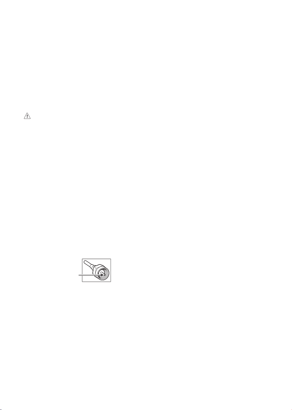
Antenna/Cable
Connect an antenna, cable, or cable box to watch TV while referring to the
following. The illustrations may differ from the actual items and an RF cable
is optional.
Copper wire
• Make sure not to bend the copper wire of the RF cable.
• Complete all connections between devices, and then connect the power
cord to the power outlet to prevent damage to your TV.
• Use a signal splitter to use 2 TVs or more.
• DTV Audio Supported Codec: MPEG, Dolby Digital
• This TV cannot receive Ultra HD (3840 x 2160 pixels) broadcasts directly
because the related standards have not been confirmed (Depending
upon country).
7
Starting TV
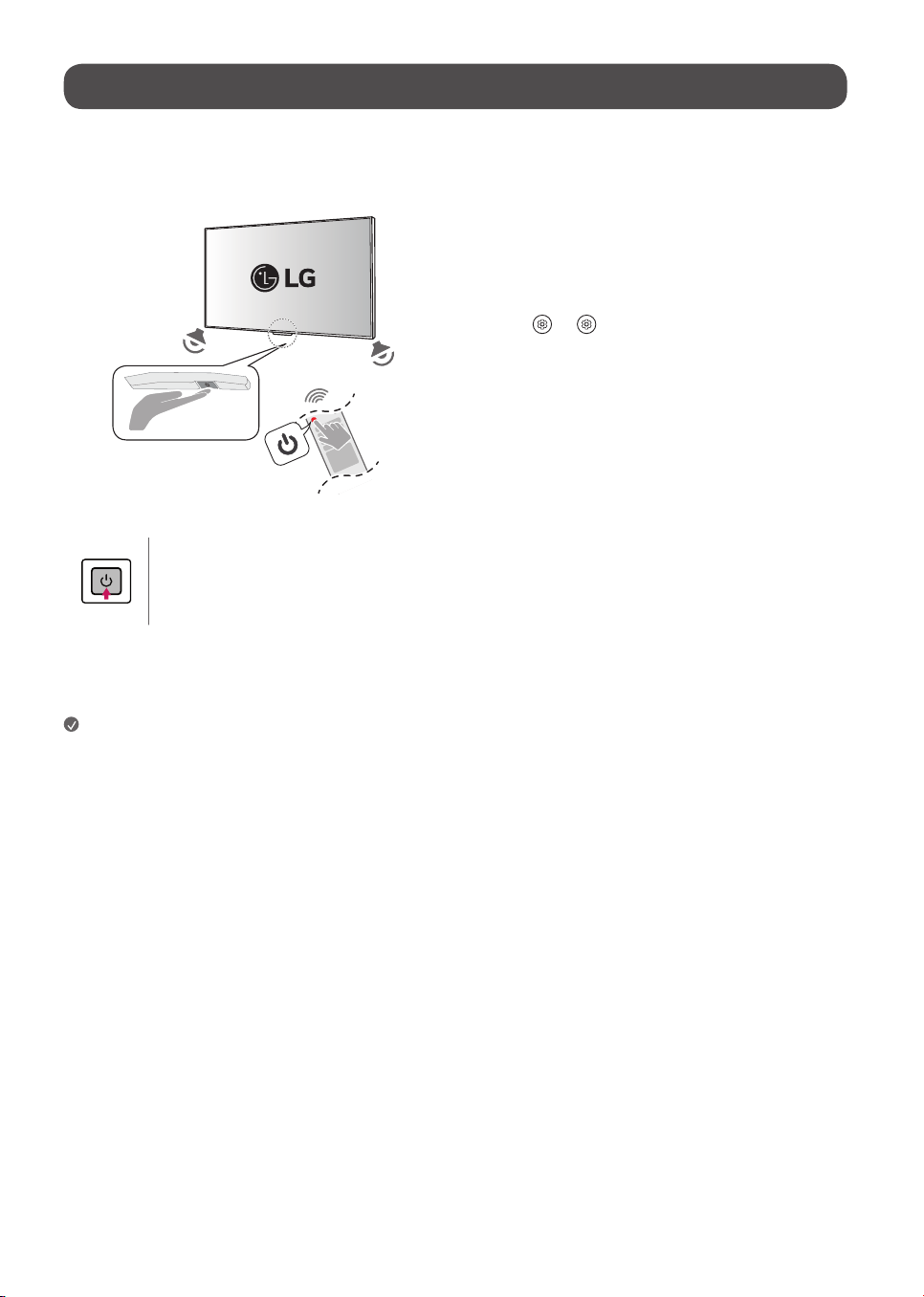
Turning on the TV
You can simply operate the TV functions, using the button.
Power On (Press)
Power Off
1)
(Press and Hold)
Menu Control (Press
2)
)
Menu Selection (Press and Hold
3)
)
1) All running apps will close.
2) You can access and adjust the menu by pressing the button when TV is on.
3) You can use the function when you access menu control.
Note
• When the TV is turned on for the first time after being shipped from the
factory, initialization of the TV may take approximately one minute.
• Your TV’s OSD (On Screen Display) may differ slightly from that shown
in this manual.
• The device must be easily accessed to a location outlet near the access.
Some devices are not made by turning on / off button, turning off the
device and unplugging the power cord.
• Only use the power button when the TV screen and the Zero Connect Box
are connected.
Using hands-free voice control
To use hands-free voice control, follow these steps.
• The voice recognition microphone is on the front bottom of the Zero
Connect Box.
1 If you direct the front LED of the Zero Connect Box towards the user, you
can use the voice recognition function smoothly.
2 Adjust the direction of the sliding button toward the TV Screen receiver by
turning the dial left or right.
3 From the
→ [ ] → [General] → [AI Service] → [Voice
Recognition Settings] screen, turn on the [Use Hands-free Voice Control]
menu. (Depending upon model)
8
Precautions before using wireless TV
Wireless TVs use high-frequency radio waves of 60 GHz to transmit a large amount of data in a very short time, enabling wireless transmission of high-quality
video and audio. The 60 GHz frequency band used in wireless TVs is advantageous for large-capacity data transmission, has good linearity, and is well-suited for
transmission and reception in a specific direction. However, if there is a metallic object in the transmission/reception path, the radio waves cannot pass through
it. Non-conductive objects (e.g., glass, wood, plastic) may attenuate the signal, resulting in communication failure. Due to such characteristics of radio waves,
viewing is not affected when the wireless TV transmitting and receiving antennas are facing each other; however, if there are obstacles in the transmission/
reception path, the wireless signal may be attenuated or disconnected, resulting in inconvenience during viewing. This is not a product malfunction. Follow the
installation method provided when using the product.
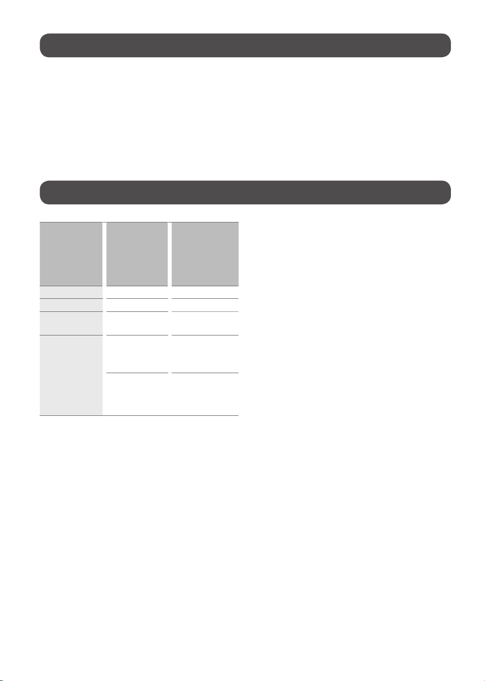
Understanding 60 GHz wireless
Characteristics of
radio waves
Frequencies in
the 60 GHz band
applied to wireless
TVs
(high frequency)
Frequencies applied
to general wireless
communication (cell
phone, WiFi/BT)
(low frequency)
Linearity Strong Weak
Transmission volume High Low
Directionality
Ideal for transmission
in specific direction
Ideal for broad
coverage
Attenuation
High loss
(linearity)
Low loss and good
avoidance (diffraction)
Radio waves
absorbed by water
droplets and water
vapour in the air
Good obstacle
avoidance
• This product satisfies the standards for protecting the human body
against electromagnetic waves*. (*Meets IEC62311 standards)
• Wireless TVs use frequencies in the 60 GHz band.
• The 60 GHz band is also known as millimetre wave (mmWave), and
enables the transmission of large data volumes without delays.
• The 60 GHz band is a high-frequency band used in satellite
communication.
• High-frequency bands have excellent linearity.
• High linearity is ideal for transmission in a specific direction; however,
obstacles cause greater attenuation loss.
• Path loss occurs due to the presence of multiple paths created by
diffraction, refraction, reflection, etc. The multiple path loss resulting
from diffraction, refraction, and reflection causes antenna transmission
and reception failure.
• Generally, wireless radio waves experience interference from
obstacles.
• Conductive obstacles (metal) shield the frequency (antenna
transmission/reception), whereas non-conductive obstacles (glass,
wood, and plastic) cause attenuation.
• Radio waves using high frequencies in the 60 GHz band (short
wavelengths) provide optimal image through the use of beamforming
technology. Beamforming technology arranges multiple antennas at
regular intervals, adjusts the amplitude and phase of the signal supplied
to each antenna, and creates an antenna beam in a specific direction to
strongly transmit and receive signals to that direction.
• For optimal image viewing, the transmission/reception must be facing
each other, that is, have an unobstructed Line Of Sight (LOS).
• LOS is the visible path, which must be clear of obstacles in the way. If
there are obstacles, the receiver must be high enough that it is visible.
That is, the receiver must be higher than the transmitter. (For wireless
TVs, the Zero Connect Box must be placed lower than the TV
Screen.)
9
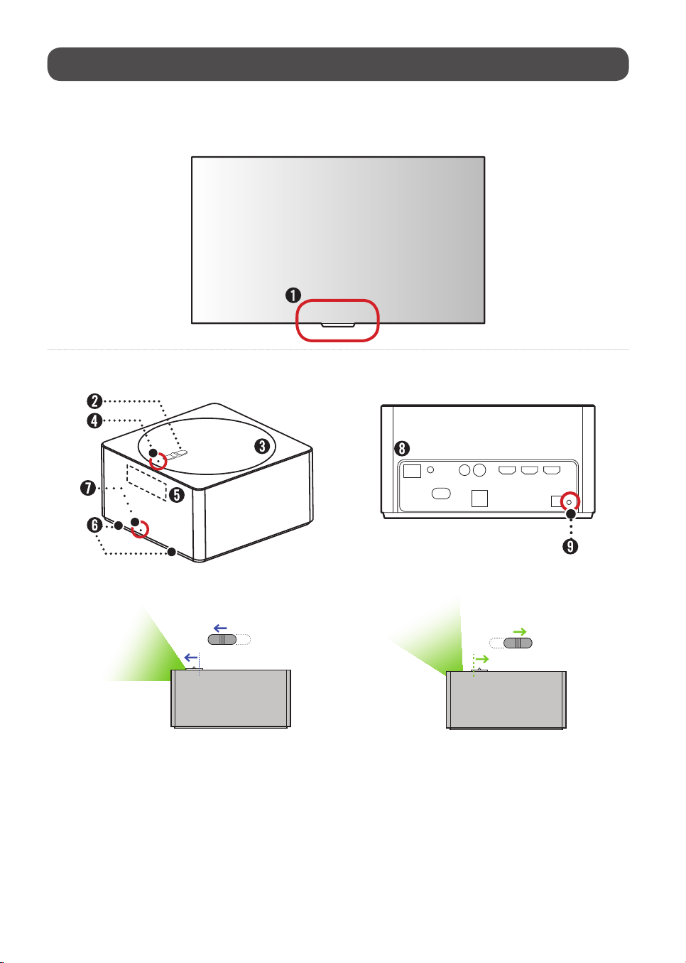
Details for wireless TV (TV Screen + Zero Connect Box)
Viewing appearance
TV Screen
Zero Connect Box (WM23EA)
Front Back
Side
10
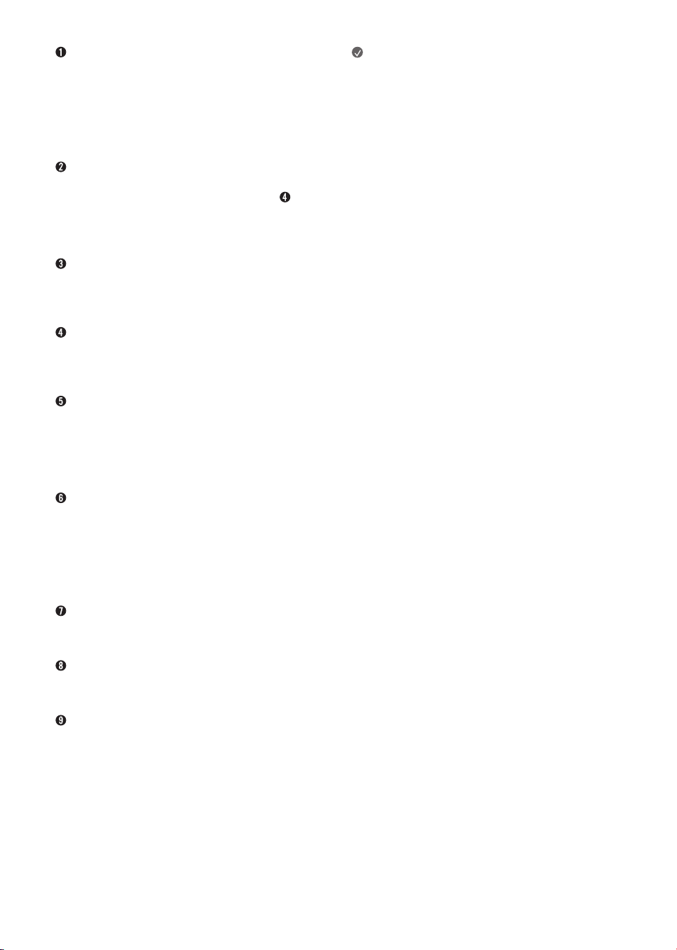
Wireless signal receiver & Power button
This area has an antenna that receives the video transmitted from the
antenna of the Zero Connect Box.
If there are any obstacles around this area, the screen may be disconnected or
not displayed due to interference.
The power button is used to turn the TV Screen on or switch to the standby
state, or pair it with the Zero Connect Box.
Sliding button
This button adjusts the antenna transmission direction of the Zero
Connect Box up and down. If adjusted towards the top LED ( ), the
antenna transmission direction is downward (0˚). If adjusted in the opposite
direction of the top LED, the antenna transmission direction is upward (50˚).
If adjusted to the center, the antenna transmission direction is at 25˚.
Dial
This disc adjusts the antenna transmission direction of the Zero
Connect Box left and right. The dial can be rotated 90˚ left or right from
the front of the Zero Connect Box.
Top LED
This LED is located in front of the sliding button and indicates the wireless
signal strength with different colors. The colors include blue (good),
green (moderate), yellow (weak), and red (disconnected).
Wireless signal transmitter
This area has an antenna that transmits video and audio from the
Zero Connect Box to the TV Screen. The antenna transmission direction
is adjusted using the dial and sliding button. If there is an obstacle in front
of the antenna, the screen may disconnect or display incorrectly due to
interference.
Voice recognition unit
This area recognizes your voice and is located on the lower left and right sides
of the front of the Zero Connect Box.
When giving a voice command, speak from the front of the Zero Connect
Box. If the area with the voice recognition parts is blocked or if you speak
from the side or back, voice recognition may function poorly or not work at
all.
Front LED
This LED is located at the bottom center of the front of the Zero Connect Box
and indicates the power or operation status.
External connection terminal
You can connect the Zero Connect Box's power cord and external video/audio
devices such as external antennas and set-top boxes.
Pairing button
This button is used to re-pair the TV Screen and Zero Connect Box if they have
been unpaired. For pairing instructions, please refer to "Re-pairing" on the
right.
Note
• The wireless TV consists of the TV Screen and Zero Connect Box.
• The Zero Connect Box transmits video and audio wirelessly to the TV
Screen.
• The Zero Connect Box has external connection terminals.
• You can connect video and audio signals (external antenna, set-top box)
to the external connection terminals on the back of the Zero Connect
Box.
• The wireless signal receiver is on the bottom center of the TV
Screen. It is next to the TV Screen power button.
• The voice recognition unit is on the lower left and right sides of the front
of the Zero Connect Box. Ensure there is no dust or foreign matter in the
small hole.
• The front LED is on the bottom of the front of the Zero Connect Box.
• The Zero Connect Box has wireless connection control terminals.
• The wireless connection control terminals consist of a dial and
a sliding button.
• The dial and wireless signal transmitter of the Zero Connect Box
move together.
• You can adjust the Zero Connect Box’s wireless signal transmitter up and
down using the sliding button.
• The signal strength LED for checking the wireless connection status is in
front of the sliding button on the top.
• The colors indicating signal strength are blue (good), green
(moderate), yellow (weak), and red (disconnected).
• The Zero Connect Box has a pairing button.
• There is a button for pairing on the TV Screen as well, which can also be
used as the power button.
• The TV Screen and the Zero Connect Box are paired one to one and are
already paired when provided.
Re-pairing
1 If the screen is not displayed due to the TV Screen and Zero Connect Box
being disconnected, they need to re-paired. If you press and hold the
pairing button on the back of the Zero Connect Box for 5 seconds, the top
LED flashes white.
2 If you press and hold the power button on the TV Screen for 5 seconds, the
standby indicator of the screen’s power unit flashes white. The TV Screen
and Zero Connect Box are now paired, and the LED on the top of the Zero
Connect Box changes to the color corresponding to the signal strength.
* If video is not displayed and the pairing screen remains, contact customer
service.
* If pairing is not resumed within one minute, it will be cancelled and must
be initiated again.
11
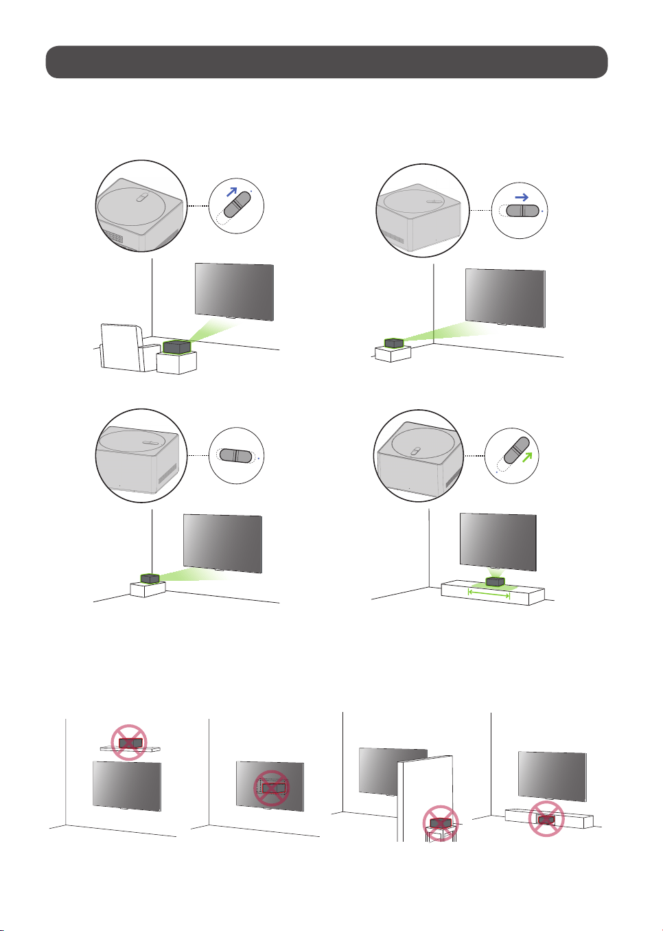
Wireless default placing and setting
Recommended installation methods (installing Zero Connect
Box)
Frontal installation Diagonal installation
Side installation Bottom installation
Installation don’ts (installing Zero Connect Box)
Installing on shelf above TV Screen Installing on wall behind TV Screen Installing behind wall Installing inside the cabinet
12
Checking before turning on wireless TV
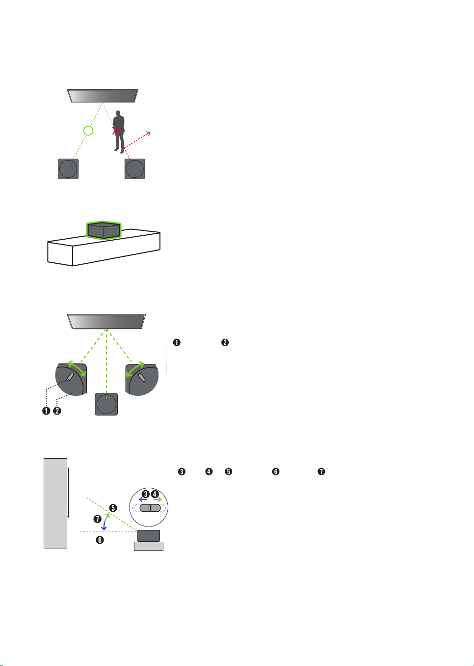
Clearing obstacles
• Remove any obstacles between the TV Screen and Zero Connect Box. If there are obstacles, the
wireless signal is attenuated and causes screen disconnection.
Placing Zero Connect Box on top of cabinet
• When using a cabinet, install the Zero Connect Box on top of the cabinet. If installed inside a cabinet,
the screen may disconnect due to interference.
• Voice recognition may also become degraded or not work at all.
Adjusting Zero Connect Box antenna left or right (dial)
Sliding button Dial
• Adjust the dial on the Zero Connect Box left or right until the sliding button faces the wireless
receiver on the TV Screen.
• By adjusting the dial, you can move the direction of the wireless signal transmission of the Zero
Connect Box left or right. You can adjust the dial up to 90˚ left or right from the front LED.
Adjusting Zero Connect Box antenna up or down (sliding button)
Down Up Highest angle Lowest angle 50˚
• Place the Zero Connect Box lower than the TV Screen wireless receiver.
• Adjust the sliding button up or down so that the wireless signal transmission direction of the Zero
Connect Box faces the TV Screen wireless signal receiver.
• If you adjust the sliding button towards the LED (blue line), the antenna transmits in a forward
straight direction. If you adjust it away from the LED (green line), the antenna transmits in an
upward direction. The Zero Connect Box antenna transmits in the 0-50˚ direction.
13
Checking after turning on wireless TV
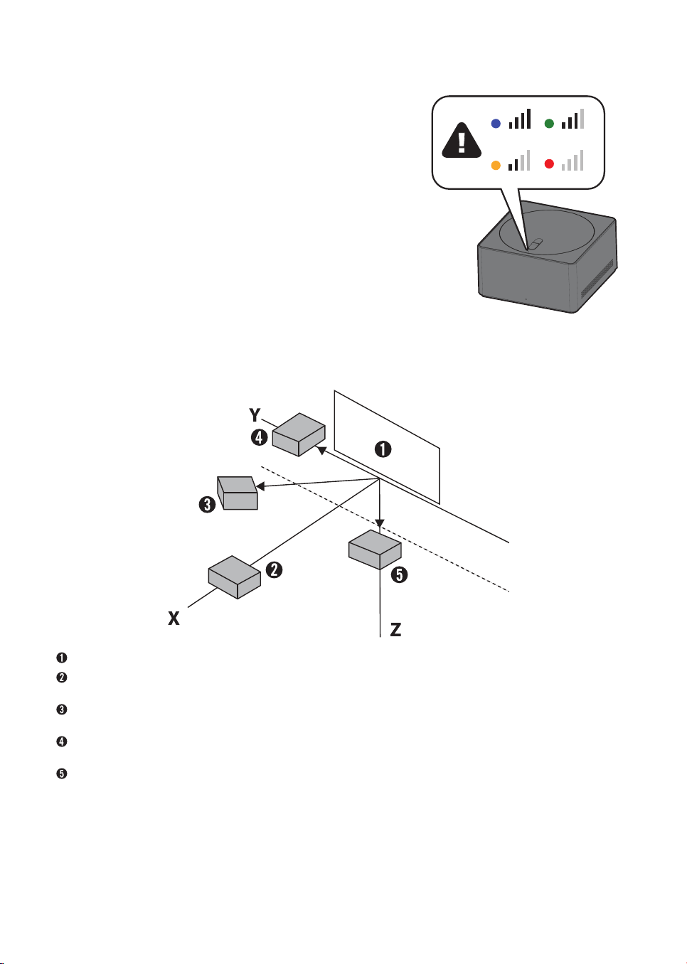
Checking wireless signal strength on Zero Connect
Box (top LED color)
• Once default placing and settings are completed, check the color of the top LED in front of the
sliding button of the Zero Connect Box.
• The color of the top LED indicates the wireless signal strength.
• The colors are blue (good), green (moderate), yellow (weak), and red (disconnected). Blue
(good) indicates the best viewing screen condition. Blue is recommended. Adjust the settings
so that the color displays blue.
Setting wireless signal strength to blue (good) on
Zero Connect Box
• If the color is red, ensure there are no obstacles or check its position on the cabinet.
• If the color is yellow or green, adjust the Zero Connect Box antenna left and right (dial) or up
and down (sliding button).
Identifying wireless reception range
TV Screen
The distance between the TV Screen antenna receiver and the Zero Connect Box antenna transmitter should be within 10 m (32.80feet) of the front
for stable operation.
The distance between the TV Screen antenna receiver and the Zero Connect Box antenna transmitter should be within 5 m (16.40feet) diagonally for
stable operation.
The distance between the TV Screen antenna receiver and the Zero Connect Box antenna transmitter should be within 3 m (9.84feet) of the side for
stable operation.
The distance between the TV Screen antenna receiver and the Zero Connect Box antenna transmitter should be within 3 m (9.84feet) of the bottom
for stable operation.
* The distances above are based on the condition that there are no obstacles. When installing a sound bar in front of the TV Screen, ensure that it does not
cover the wireless receiver on the TV Screen. It is recommended to install the sound bar at a sufficient distance from the wireless receiver on the TV Screen.

14
Precaution Notes
Wireless Precaution Notes
• The quality of the image and audio may deteriorate depending upon the installation environment (installed location, surrounding
devices, obstacles, and distance).
• Do not place obstacles between the TV Screen and Zero Connect Box. The screen may fail to display due to interference from obstacles.
• Ensure that there are no obstacles between the Zero Connect Box and TV Screen.
• If the Zero Connect Box is installed inside the cabinet, the screen may fail to display, depending upon the cabinet material (marble, wood, etc.) and
thickness, and the voice recognition function may also deteriorate.
• Do not install two wireless TVs or Zero Connect Boxes in the same room. The screen may fail to display due to interference.
• When used with an external device using a 60 GHz frequency, the screen may fail to display due to mutual interference.
• If you place electronic devices and objects on top of the Zero Connect Box, the screen may fail to display properly due to interference.
• If a person or animal passes between the Zero Connect Box and the TV Screen while you are watching TV, the screen may disconnect.
• Failure to follow the recommended installation method may result in abnormal operation.
Voice Recognition Precaution Notes
• Speaking from directions other than the front of the Zero Connect Box where the voice recognition unit is located may cause the voice recognition
function to deteriorate.
• Do not place any obstacles in front of the Zero Connect Box where the voice recognition unit is located.
• Please keep the small hole of the voice recognition unit free from dust or any foreign matter.
• Failure to follow the recommended installation method may result in poor or non-functional voice recognition.
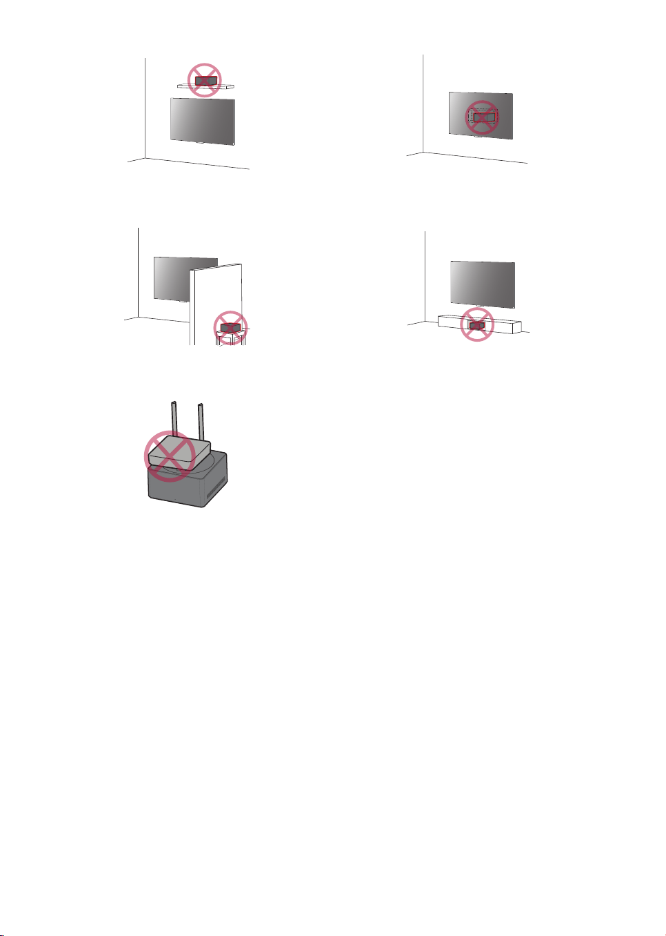
Installation Precaution Notes
• Do not install the Zero Connect Box on a shelf above the TV Screen. The antenna path does not align with the Zero Connect Box antenna transmitter and
the screen does not display properly due to shelf interference.
• Do not install the Zero Connect Box on the wall behind the TV Screen. The screen does not display because the wireless signal is shielded.
• Do not install the Zero Connect Box behind a wall. The screen does not display because the wireless signal is shielded by the wall.
• Do not install the Zero Connect Box inside a metal cabinet. The screen does not display because the signal is shielded. Thick materials such as marble,
glass, or wood may also cause wireless failure and prevent the screen from displaying properly.
• Failure to follow the recommended installation method may result in the screen not displaying.
• Ensure that the wireless receiver on the TV Screen does not come into contact with the wireless transmitter on the Zero Connect Box.
• After cleaning or moving the Zero Connect Box, check and adjust the color of the LED on the top. The screen may not display because of the change in
installation environment.
15
Installing on shelf above TV Screen Installing on wall behind TV Screen
Installing behind wall Installing inside the cabinet
Placing electronic devices on top of Zero Connect Box
16
Installing according to usage scenarios
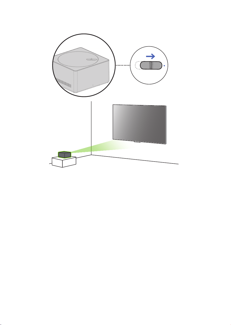
Installing Zero Connect Box in front of TV Screen
Checking before turning on wireless TV
If you have installed the Zero Connect Box in front of the TV Screen, follow these steps.
1 Direct the front LED of the Zero Connect Box towards the wireless receiver on the TV Screen.
2 If the front LED is not directed towards the TV Screen wireless receiver, turn the dial on top of the Zero Connect Box left or right until the sliding button
faces the TV Screen wireless receiver.
3 Adjust the sliding button on the Zero Connect Box towards the top LED.
• Once the dial and sliding button adjustments are completed, the signal transmission and reception path should be in the green direction shown in the
figure.
• Ensure there are no obstacles in the antenna transmission and reception path.
Checking after turning on wireless TV
1 Once you have completed all settings, check that the color of the top LED of the Zero Connect Box is blue.
2 If the LED is not blue, adjust the dial and sliding button further to optimize the signal condition.
• It is recommended that the installation distance between the Zero Connect Box and the TV Screen be within 10 m (32.80feet). (provided that there are
no obstacles in the way)
• It is recommended that the frontal installation angle between the Zero Connect Box and the TV Screen be within 45˚ left and right. (Refer to the
diagonal/side installation image if the angle is over 45˚.)
17
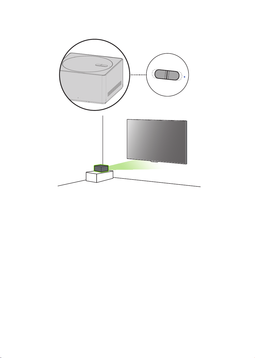
Installing Zero Connect Box diagonally from TV Screen
Checking before turning on wireless TV
If you have installed the Zero Connect Box diagonally from the TV Screen, follow these steps.
1 Direct the front LED of the Zero Connect Box towards the wireless receiver on the TV Screen.
2 If the front LED is not directed towards the TV Screen wireless receiver, turn the dial on top of the Zero Connect Box left or right until the sliding button
faces the TV Screen wireless receiver.
3 Adjust the sliding button on the Zero Connect Box towards the top LED.
• Once the dial and sliding button adjustments are completed, the signal transmission and reception path should be in the green direction shown in the
figure.
• Ensure there are no obstacles in the antenna transmission and reception path.
Checking after turning on wireless TV
1 Once you have completed all settings, check that the color of the top LED of the Zero Connect Box is blue.
2 If the LED is not blue, adjust the dial and sliding button further to optimize the signal condition.
• It is recommended that the installation distance between the Zero Connect Box and the TV Screen be within 5 m (16.40feet). (provided that there are
no obstacles in the way)
18
Installing Zero Connect Box to the side of TV Screen
Checking before turning on wireless TV
If you have installed the Zero Connect Box to the side of the TV Screen, follow these steps.
1 Direct the front LED of the Zero Connect Box towards the wireless receiver on the TV Screen.
2 If the front LED is not directed towards the TV Screen wireless receiver, turn the dial on top of the Zero Connect Box left or right until the sliding button
faces the TV Screen wireless receiver. (If the front LED of the Zero Connect Box faces the viewing direction, turn the dial left or right until it is at a 90°
angle.)
3 Adjust the sliding button on the Zero Connect Box to the center.
• Once the dial and sliding button adjustments are completed, the signal transmission and reception path should be in the green direction shown in the
figure.
• Ensure there are no obstacles in the antenna transmission and reception path.
Checking after turning on wireless TV
1 Once you have completed all settings, check that the color of the top LED of the Zero Connect Box is blue.
2 If the LED is not blue, adjust the dial and sliding button further to optimize the signal condition.
• It is recommended that the installation distance between the Zero Connect Box and the TV Screen be within 3 m (9.84feet). (provided that there are no
obstacles in the way)in the way)
19
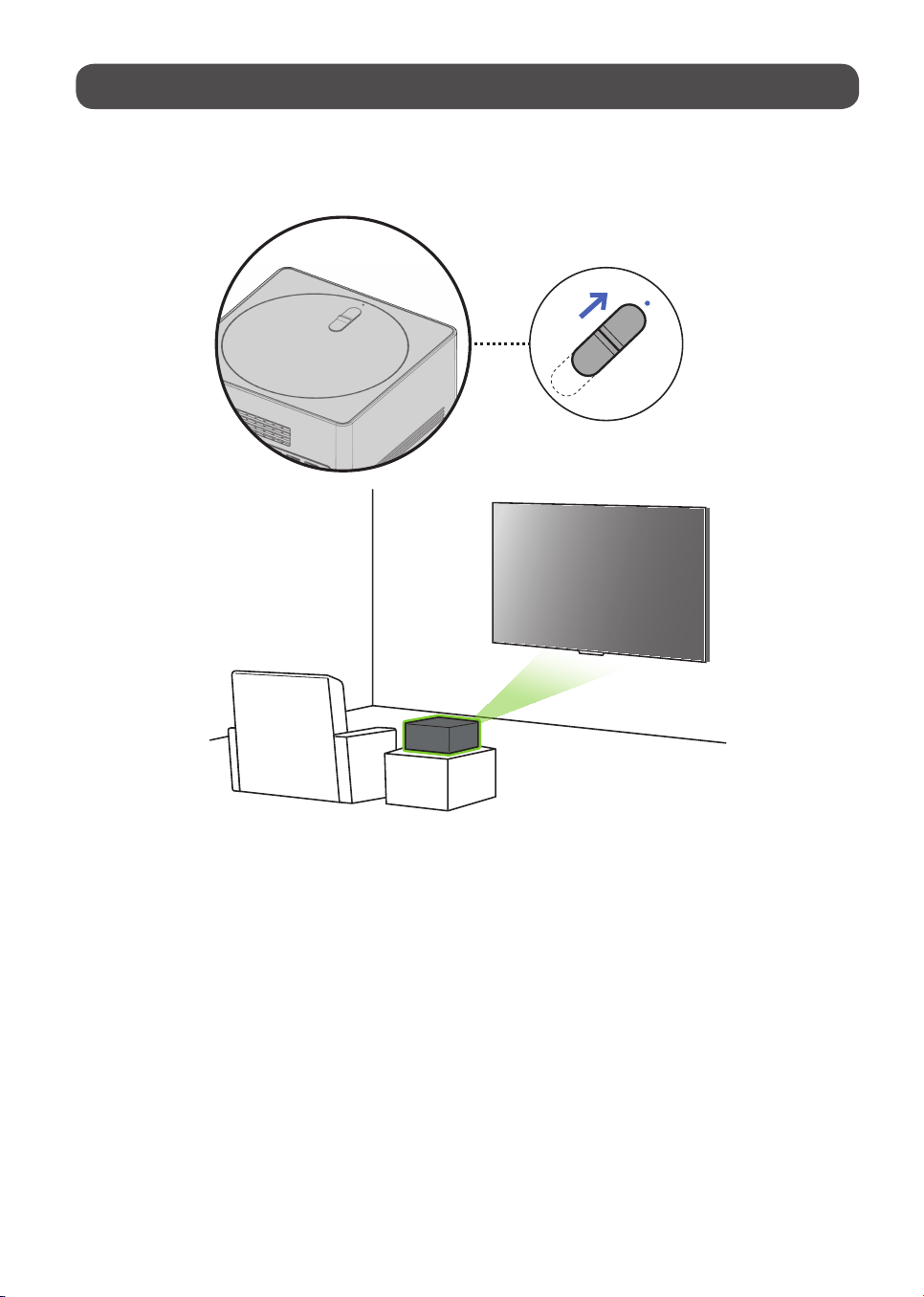
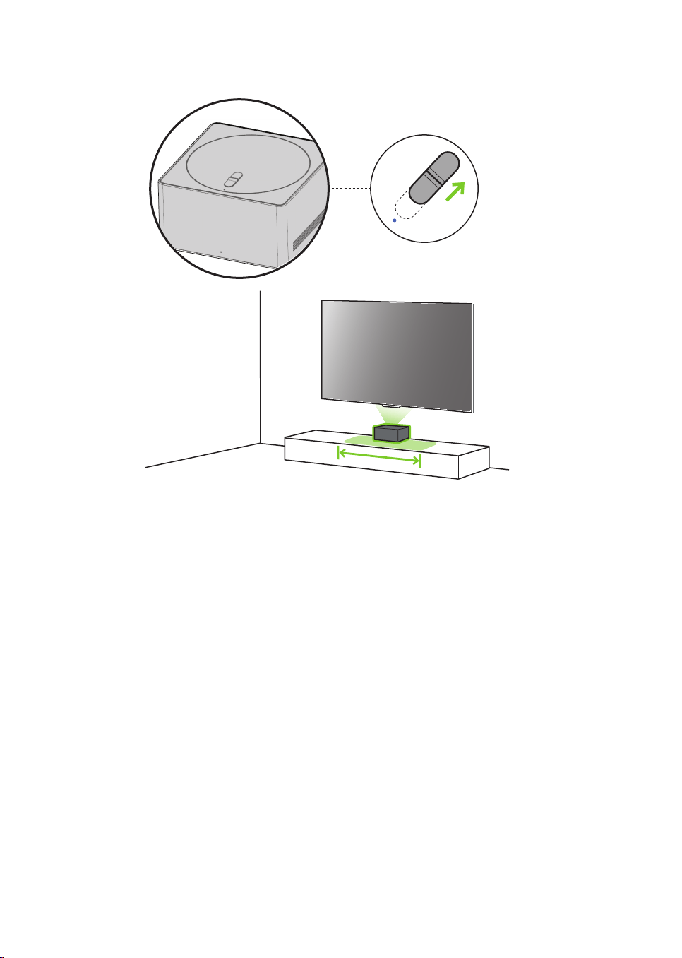
Installing Zero Connect Box to the bottom of TV Screen
Checking before turning on wireless TV
If you have installed the Zero Connect Box to the bottom of the TV Screen, follow these steps.
1 Position the Zero Connect Box so that the front LED is facing the viewer in front of the TV Screen.
2 Turn the dial on the top of the Zero Connect Box left or right to adjust the direction of the sliding button towards the viewer.
3 Adjust the sliding button on the Zero Connect Box in the opposite direction of the top LED.
• Once the dial and sliding button adjustments are completed, the signal transmission and reception path should be in the green direction shown in the
figure.
• Ensure there are no obstacles in the antenna transmission and reception path.
Checking after turning on wireless TV
1 Once you have completed all settings, check that the color of the top LED of the Zero Connect Box is blue.
2 If the LED is not blue, adjust the dial and sliding button further to optimize the signal condition.
• It is recommended that the installation distance between the Zero Connect Box and the TV Screen be within 3 m (9.84feet). (provided that there are no
obstacles in the way)
* When installing the Zero Connect Box at the bottom of the TV screen, please do so within the area indicated in the figure. For installation outside the
highlighted area on the cabinet, refer to "Installing Zero Connect Box to the side of TV Screen."
20
Connections
You can connect various external devices to the TV. For more information on
external device’s connection, refer to the manual provided with each device.
HDMI
• When connecting the HDMI cable, the product and external devices
should be turned off and unplugged.
• Supported HDMI Audio format (Depending upon model):
True HD (48kHz),
Dolby Digital / Dolby Digital Plus (32kHz, 44.1kHz, 48kHz),
PCM (32kHz, 44.1kHz, 48kHz, 96kHz, 192kHz),
DTS (44.1kHz, 48kHz, 88.2kHz, 96kHz),
DTS-HD (44.1kHz, 48kHz, 88.2kHz, 96kHz, 176.4kHz, 192kHz)
Note
• If the device connected to Input Port also supports HDMI Deep Color,
your picture may be clearer. However, if the device doesn’t support it, it
may not work properly. In that case, change the TV’s [HDMI Deep Color]
setting to off.
•
→ [ ] → [General] → [External Devices] → [HDMI Settings]
→ [HDMI Deep Color]
• Use a certified cable with the HDMI logo attached. If you do not use a
certified HDMI cable, the screen may not display or a connection error
may occur.
• Recommended HDMI cable types
- Ultra High Speed HDMI
®
/™ cable (3m (9.84feet) or less)
USB
You can connect a USB hub that enables you to use multiple USBs
simultaneously to the Zero Connect Box.
Some USB Hubs may not work. If a USB device connected using a USB Hub is
not detected, connect it to the USB port on the zero connect box directly.
Note
• For an optimal connection, HDMI cables and USB devices should have
bezels less than 10mm (0.39inches) thick and 18mm (0.7inches)
width. (Depending upon model)
• Use an extension cable that supports
if the USB cable or USB
memory stick does not fit into your zero connect box’s USB port.
IR Blaster
Control the set-top box (cable/satellite/IP/OTT), Blu-ray/DVD player,
soundbar, game consoles, etc., using the IR Blaster. (Depending upon country)
Note
• Connect the IR Blaster cable to the TV’s IR Blaster port.
• Use universal control settings to control the device.
• Secure the IR Blaster with the 3M tape provided.
• In order to control external devices through "Room to Room Share" and
"Hands-free Voice Control", an IR blaster connection is required.
• When installing the Zero Connect Box in a location other than the
bottom of the TV, we recommend connecting an IR blaster to ensure
smooth control of external devices (e.g., set-top box) using your TV
remote control.
External Devices
Available external devices are: Blu-ray player, HD receivers, DVD players, VCRs,
audio systems, USB storage devices, PC, gaming devices, and other external
devices.
Note
• The external device connections shown may differ slightly from
illustrations in a manual.
• In PC mode, there may be noise associated with the resolution, vertical
pattern, contrast or brightness. If noise is present, change the PC output
to another resolution, change the refresh rate to another rate or adjust
the brightness and contrast on the [Picture] menu until the picture is
clear. Depending upon the graphics card, some resolution settings may
not allow the image to be positioned on the screen properly.
• When connecting to a wired LAN, use a CAT7 cable with high-speed
Internet transmission. (Only when
port is provided.)
• The TV may be capable of operating without a set-top-box from a
multichannel video programming distributor (MVPD).
• TV audio can be transmitted to the sound bar (external audio device).
(Depending upon country)
- If you want to transmit audio in a wired way (optical digital, HDMI
ARC), you can connect it to the external terminal on the rear of the
Zero Connect Box.
- You can wirelessly transmit audio through the WOWCAST function to
our sound bars that support WOWCAST.
Remote RS-232C setup
To obtain the RS-232C external control setup information, please visit www.
lg.com. Download and read the manual, (Depending upon model).
• Do not drop the product or let it fall over when connecting external
devices. Otherwise, this may result in injury or damage to the product.
• When connecting external devices such as video game consoles, make
sure the connecting cables are long enough. Otherwise, the product may
fall over, which may cause injury or damage the product.
21
Specications
Power requirement AC 120 V~ 50/60 Hz
Product specifications may be changed without prior notice due to upgrade of product functions.
Estimated yearly energy consumption indicated on the FTC label is measured in accordance with the Test Procedures for Television Sets (USA only).
The actual energy consumption depends on the usage environment (The content watched, TV settings, etc.).
• For information of the power supply and power consumption, refer to the label attached to the product.
- The typical power consumption is measured in accordance with IEC 62087 or each country’s energy regulations.
- See the label on the bottom of the product for power source, power ratings and product information.
* On some models, the label is inside the external device connection terminal cover.
* Depending upon the model or country, the typical power consumption may not be on label.
(Depending upon country)
Broadcasting Specifications
Television system Terrestrial / Cable / Satellites Digital TV
External antenna impedance 75Ω
Environment Condition
Operating Temperature
0 °C to 40 °C
(32 °F to 104 °F)
Storage Temperature
-20 °C to 60 °C
(-4 °F to 140 °F)
Operating Humidity Less than 80% Storage Humidity Less than 85%
Conditions for Wall Mount Installation
Tilt Angle 0° - 15°
* This specification range applies to TV wall mounts when adjusting for proper viewing angle.
22
Product Information
Open Source Software Notice
Information
To obtain the source code that is contained in this product, under GPL, LGPL,
MPL, and other open source licenses that have the obligation to disclose
source code, and to access all referred license terms, copyright notices and
other relevant documents please visit https://opensource.lge.com.
LG Electronics will also provide open source code to you on CD-ROM for a
charge covering the cost of performing such distribution (such as the cost of
media, shipping, and handling) upon email request to opensource@lge.com.
This offer is valid to anyone in receipt of this information for a period of three
yearsafter our last shipment of this product.
Licenses
(Magic Remote supported models only)
23
Troubleshooting
In TV / HDMI input, press the button on the remote control three times to display the model name and serial number on the screen.
Cannot control the TV with
the remote control.
• Check if anything such as tape has been placed over the receiver.
• Check if there is any obstacle between the product and the remote control.
• Replace the batteries with new fresh ones.
No image display and no
sound is produced.
• Check if the product is turned on.
• Check if the power cord is connected to a wall outlet.
• Check if there is a problem in the wall outlet by connecting other products.
The TV turns off suddenly. • Check the power control settings. The power supply may be interrupted.
• Check if the auto-off function is activated in the settings menu.
• The auto-off function may have worked. This product is equipped with an auto-off function that automatically
turns off the power if the remote control is not used for 15 minutes without an input signal.
Abnormal Display • If the product feels cold to the touch, there may be a small “flicker” when it is turned on. This is normal, there is
nothing wrong with product.
• This panel is an advanced product that contains millions of pixels. You may see tiny black dots and/or brightly
colored dots (white, red, blue or green) at a size of 1 ppm on the panel. This does not indicate a malfunction and
does not affect the performance and reliability of the product. This phenomenon also occurs in third-party products
and is not subject to exchange or refund.
• You may find different brightness and color of the panel depending upon your viewing position(left/right/
top/down). This phenomenon occurs due to the characteristic of the panel. It is not related with the product
performance, and it is not malfunction.
• Avoid touching the screen or holding your finger(s) against it for long periods of time. Doing so may produce some
temporary distortion effects on the screen.
Generated Sound • Cracking noise A cracking noise that occurs when watching or turning off the TV is generated by plastic thermal
contraction due to temperature and humidity. This noise is common for products where thermal deformation is
required.
• Electrical circuit humming/panel buzzing A low level noise is generated from a high-speed switching
circuit, which supplies a large amount of current to operate a product. It varies depending upon the product. This
generated sound does not affect the performance and reliability of the product.
• Fan noise: It is a sound made to dissipate the heat generated by the Zero Connect Box, and does not make the
product defective.
A Zero Connect Box
connection image appears
on the screen.
• Clear any objects between the TV screen and the Zero Connect Box.
• Turn the dial on the top of the Zero Connect Box left or right.
• Move the sliding button on the top of the Zero Connect Box up or down.
A power connection image
appears on the screen.
• Connect the power cord of the Zero Connect Box.
24
The product does not
turn on continuously due
to Always Ready mode
operation or does not
automatically turn on by
sensor.
• The motion sensor is located on the bottom center of the product.
• The motion sensor is only supported by some models.
• If there is a foreign substance on the motion sensor, it may not work properly.
• If the environment around the product is too bright or too dark, the motion sensor may not work properly.
• Obstacles in front of the product may affect the detection function of the motion sensor.
• It can operate by recognising changes in lighting around the product or movement of objects (pets/robot vacuum
cleaners, etc.).
• To stop using the Always Ready mode in → [ ] → [General] → [Always Ready] → [Enable the function],
or to use only the General Always Ready mode function, you can select Enable Always Ready mode, turn off the
screen, and then stop using the motion sensor in [Always Ready Settings]. The screen-on function with the motion
sensor can be set by adjusting the performance of the sensor through the [Always Ready Settings] → [Motion
Sensor Sensitivity] setting.
Hands-free Voice Control
does not work properly.
• Direct the front of the Zero Connect Box towards the user.
• Turn the dial on the top of the Zero Connect Box left or right to adjust the direction of the sliding button towards
the TV Screen receiver.
• From the → [ ] → [General] → [AI Service] → [Voice Recognition Settings] screen, turn on the [Use
Hands-free Voice Control] menu. (Depending upon model)
• Make sure to wring any excess water or cleaner from the cloth.
• Do not spray water or cleaner directly onto the TV screen.
• Make sure to spray just enough of water or cleaner onto a dry cloth to wipe the screen.
25
Precautions for Protecting the OLED TV Screen
Unlike regular LED/LCDs, OLED TVs produce images that emit light for each
pixel, achieving a perfect black color and delivering clear images without
blurring.
Due to the nature of the organic materials used to achieve high-resolution
image quality, OLED displays generally experience image retention on the
screen, which can be a persistent phenomenon. This phenomenon is observed
in all OLED panels, and although recommended picture modes can minimize
image retention, current technology cannot completely prevent this from
occurring.
Displaying the same image for a long time or repeatedly displaying the
same image can cause image retention on the screen, which is a common
phenomenon in OLED panel products due to the nature of the product. This
product has a built-in screen protection feature. Avoid displaying images that
are likely to cause image retention, and follow the recommendations.
Images that are likely to cause image
retention
• Images with black areas on the top and bottom and/or the left and right
sides of the screen.
• Images whose aspect ratio is 4:3 or 21:9.
• Images that are fixed for a long time, such as channel number, station
logo, game console icon, set-top box menu, etc.
• Other fixed screen images or repeatedly displayed images.
Running [Pixel Cleaning] to Protect the
OLED TV Screen
The OLED TV is equipped with a pixel cleaning feature to check the status of
the screen by itself and prevent image retention that leaves an image on a
screen. This feature automatically calculates the optimal execution time based
on the accumulated viewing time and is automatically executed when the
TV is turned off. While this feature is running, horizontal lines may appear at
the top and bottom of the screen. The pixel cleaning feature works when the
product is connected to the power cord and main power.
• To run this function manually, press the
button on the remote
control, go to [ ] → [General] → [OLED Care] → [OLED Panel Care]
and press [Pixel Cleaning].
Recommendations for Minimizing
Image Retention
When watching the TV for a long time, press the button on the remote
control, go to [ ] → [Picture] → [Select Mode] and set the mode to [Auto
Power Save], go to [Advanced Settings] → [Brightness] and set [OLED Pixel
Brightness] to a lower level. In addition, press the button on the remote
control, go to [ ] → [General] → [OLED Care] → [OLED Panel Care] and
set the [Adjust Logo Brightness] value to [High].
When showing images with black bars at the top/bottom/left/right side of
the screen, press the
button on the remote control, go to [ ], and go to
[Picture] → [Aspect Ratio] → [User Selection] → [Vertical Zoom] or [4-Way
Zoom] to remove the black bars.
Turn off the menus for setting up devices such as set-top boxes so that they
are not displayed on the screen for a long time.
Note
• When the screen is showing one fixed image for a long time, the screen
brightness will be automatically reduced and then restored once the
screen content changes. This is a normal function to minimize image
retention.
26
Regulatory
-
-
-
-
27
LG Take-back & Recycling Policy
(1)
(2)
(3)
(4)
NOTE TO CABLE/TV INSTALLER
(For USA and Canada)
This reminder is provided to call the CATV system installer’s attention to Article 820-40 of the National Electric Code (U.S.A.). The code provides guidelines for
proper grounding and, in particular, specifies that the cable ground shall be connected to the grounding system of the building, as close to the point of the cable
entry as practical.
WARNING! (STABILITY HAZARD)
A television set may fall, causing serious personal injury or death. Many injuries, particularly to children, can be avoided by taking simple precautions such as:
- ALWAYS use cabinets or stands or mounting methods recommended by the manufacturer of the television set.
- ALWAYS use furniture that can safely support the television set.
- ALWAYS ensure the television set is not overhanging the edge of the supporting furniture.
- ALWAYS educate children about the dangers of climbing on furniture to reach the television set or its controls.
- ALWAYS route cords and cables connected to your television so they cannot be tripped over, pulled or grabbed.
- NEVER place a television set in an unstable location.
- NEVER place the television set on tall furniture (for example, cupboards or bookcases) without anchoring both the furniture and the television set to a
suitable support.
- NEVER place the television set on cloth or other materials that may be located between the television set and supporting furniture.
- NEVER place items that might tempt children to climb, such as toys and remote controls, on the top of the television or furniture on which the television
is placed.
If the existing television set is going to be retained and relocated, the same considerations as above should be applied.
Symbols
Refers to alternating current (AC). Refers to stand-by.
Refers to direct current (DC). Refers to “ON” (power).
Refers to class II equipment. Refers to dangerous voltage.

28

OWNER’S MANUAL
EXTERNAL CONTROL
DEVICE SETUP
Please read this manual carefully before operating the set and retain it for
future reference.
www.lg.com
P/NO : MFL71445401 (1901-REV00)

2
ENG
ENGLISH
2
KEY CODES
KEY CODES
• This feature is not available for all models.
Code
(Hexa)
Function Note
Code
(Hexa)
Function Note
00 CH +, PR + R/C Button 53 List R/C Button
01 CH -, PR - R/C Button 5B Exit R/C Button
02 Volume + R/C Button 60 PIP(AD) R/C Button
03 Volume - R/C Button 61 Blue R/C Button
06 > (Arrow Key / Right Key) R/C Button 63 Yellow R/C Button
07 < (Arrow Key / Left Key) R/C Button 71 Green R/C Button
08 Power R/C Button 72 Red R/C Button
09 Mute R/C Button 79 Ratio / Aspect Ratio R/C Button
0B Input R/C Button 91 AD (Audio Description) R/C Button
0E SLEEP R/C Button 9E LIVE MENU R/C Button
0F TV, TV/RAD R/C Button 7A User Guide R/C Button
10 - 19 * Number Key 0 - 9 R/C Button 7C Smart / Home R/C Button
1A Q.View / Flashback R/C Button 7E SIMPLINK R/C Button
1E FAV (Favorite Channel) R/C Button 8E ►►(Forward) R/C Button
20 Text (Teletext) R/C Button 8F ◄◄(Rewind) R/C Button
21 T. Opt (Teletext Option) R/C Button AA Info R/C Button
28 Return (BACK) R/C Button AB Program Guide R/C Button
30 AV (Audio / Video) Mode R/C Button B0 ►(Play) R/C Button
39 Caption/Subtitle R/C Button B1 ꕗ (Stop / File List) R/C Button
40 Λ
(Arrow Key / Cursor Up)
R/C Button B5 RECENT R/C Button
41
V (Arrow Key / Cursor
Down)
R/C Button BA
ꕘ (Freeze / Slow Play /
Pause)
R/C Button
42 My Apps R/C Button BB Soccer R/C Button
43 Menu / Settings R/C Button BD ꔄ (REC) R/C Button
44 OK / Enter R/C Button DC 3D R/C Button
45 Q.Menu R/C Button 99 AutoConfig R/C Button
4C List, - R/C Button 9F App / * R/C Button
4D PICTURE R/C Button 9B TV / PC R/C Button
52 SOUND R/C Button
* Key code 4C (0x4C) is available on ATSC/ISDB models which use major/minor channel.
(For South Korea, Japan, North America, Latin America except Colombia models)
3
ENGENGLISH
3
EXTERNAL CONTROL DEVICE SETUP
EXTERNAL CONTROL DEVICE SETUP
• Image shown may differ from your TV.
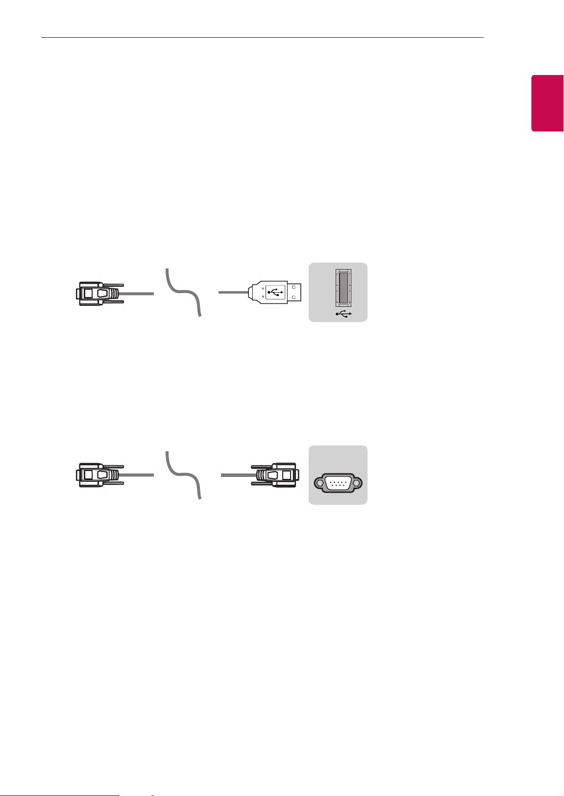
Connect the USB to Serial(RS-232C) converter/RS-232C(Serial) input jack to an external control device
(such as a computer or an A/V control system) to control the product’s functions externally.
Note: The type of control port on the TV can be different between model series.
* Please be advised that not all models support this type of connectivity.
* Cable is not provided.
USB to Serial(RS-232C) converter with USB Cable
USB Type
USB IN
(TV)
(PC )
(PC
)
RS-232C IN
(CONTROL & SERVICE)
(TV)
(TV)
(PC )
(TV)
(PC )
SERVICE ONLY
RS-232C IN
(CONTROL & SERVICE)
RS-232C IN
(CONTROL & SERVICE)
1
3
2
1
3
2
• LGTV supports PL2303 chip-based (Vendor ID : 0x0557, Product ID : 0x2008) USB to serial(RS-232C)
converter which is not made nor provided by LG.
• It can be purchased from computer stores that carry accessories for IT support professionals.
RS-232C(Serial) With RS-232C(Serial) Cable
DE9 (D-Sub 9pin) Type
• You need to purchase the RS-232C (DE9, D-Sub 9pin female-to-female type) to RS-232C(Serial) cable
required for the connection between the PC and the TV, which is specified in the manual.
USB IN
(TV)
(PC
)
(PC )
RS-232C IN
(CONTROL & SERVICE)
(TV)
(TV)
(PC )
(TV)
(PC )
SERVICE ONLY
RS-232C IN
(CONTROL & SERVICE)
RS-232C IN
(CONTROL & SERVICE)
1
3
2
1
3
2
The connection interface may differ from your TV.
4
ENG
ENGLISH
4
EXTERNAL CONTROL DEVICE SETUP
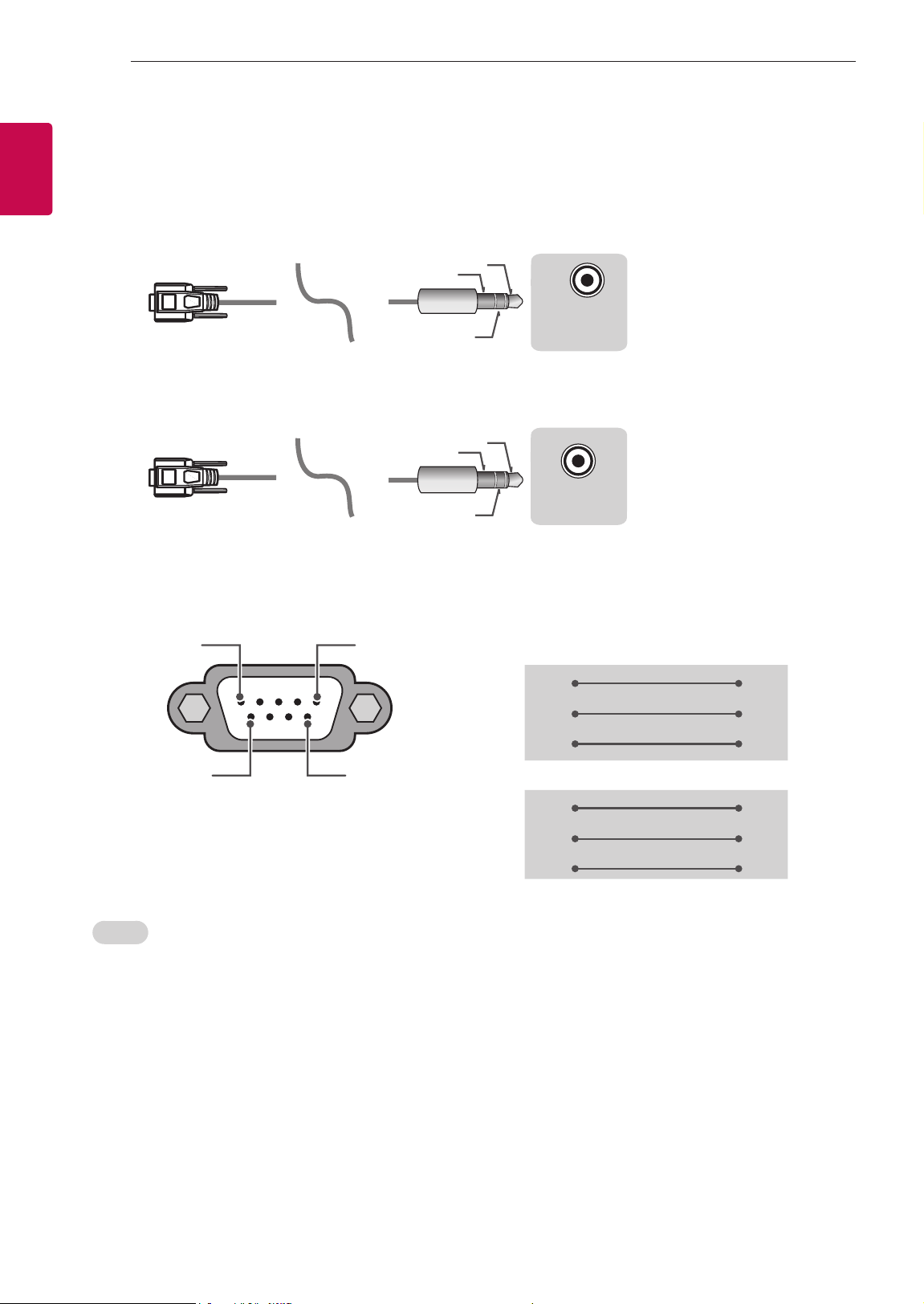
Phone jack Type
• You need to purchase the phone-jack to RS-232 cable required for the connection between the PC and
the TV, which is specified in the manual.
* For other models, connect to the USB port.
* The connection interface may differ from your TV.
USB IN
(TV)
(PC )
(PC )
RS-232C IN
(CONTROL & SERVICE)
(TV)
(TV)
(PC
)
(TV)
(PC )
SERVICE ONLY
RS-232C IN
(CONTROL & SERVICE)
RS-232C IN
(CONTROL & SERVICE)
1
3
2
1
3
2
- or
USB IN
(TV)
(PC )
(PC )
RS-232C IN
(CONTROL & SERVICE)
(TV)
(TV)
(PC )
(TV)
(PC
)
SERVICE ONLY
RS-232C IN
(CONTROL & SERVICE)
RS-232C IN
(CONTROL & SERVICE)
1
3
2
1
3
2
Customer Computer RS-232C configurations
3-Wire Configurations(Not standard)
1
6
5
9
PC TV
RXD 2 2 TXD
TXD 3 1 RXD
GND 5 3 GND
OR
RXD 3 2 TXD
TXD 2 1 RXD
GND 5 3 GND
D-Sub 9 Phone
RS-232C
(Serial port)
Set ID
For Set ID number, see "Real Data Mapping" on p.6
1. Press SETTINGS to access the main menus.
2. Press the Navigation buttons to scroll to (*General → About this TV or OPTION) and press OK.
3. Press the Navigation buttons to scroll to SET ID and press OK.
4. Scroll left or right to select a set ID number and select CLOSE. The adjustment range is 1-99.
5. When you are finished, press EXIT.
* (Depending on model)
5
ENGENGLISH
5
EXTERNAL CONTROL DEVICE SETUP
Communication Parameters
• Baud rate : 9600 bps (UART)
• Data length : 8 bits
• Parity : None
• Stop bit : 1 bit
• Communication code : ASCII code
• Use a crossed (reverse) cable.
Command reference list
(Depending on model)
COMMAND1 COMMAND2
DATA
(Hexadecimal)
COMMAND1 COMMAND2
DATA
(Hexadecimal)
01. Power* k a 00 to 01 15. Balance k t 00 to 64
02. Aspect
Ratio
k c (p.7)
16. Color
(Colour)
Temperature
x u 00 to 64
03. Screen
Mute
k d (p.7)
17. ISM
Method (Only
Plasma TV)
j p (p.8)
04. Volume
Mute
k e 00 to 01 18. Equalizer j v (p.9)
05. Volume
Control
k f 00 to 64
19. Energy
Saving
j q 00 to 05
06. Contrast k g 00 to 64
20. Tune
Command
m a (p.9)
07.
Brightness
k h 00 to 64
21. Channel
(Programme)
Add/Del(Skip)
m b 00 to 01
08. Color/
Colour
k i 00 to 64 22. Key m c Key Codes
09. Tint k j 00 to 64
23. Control
Backlight,
Control Panel
Light
m g 00 to 64
10.
Sharpness
k k 00 to 32
24. Input
select (Main)
x b (p.11)
11. OSD
Select
k l 00 to 01
25. 3D (Only
3D models)
x t (p.11)
12. Remote
Control Lock
Mode
k m 00 to 01
26. Extended
3D (Only 3D
models)
x v (p.12)
13. Treble k r 00 to 64
27. Auto
Configure
j u (p.12)
14. Bass k s 00 to 64
* Note: During playing or recording media, all commands except Power (ka) and Key (mc) are not
executed and treated as NG.
With RS232C cable, TV can communicate "ka command" in power-on or power-off status. but with
USB-to-Serial converter cable, the command works only if TV is on.

6
ENG
ENGLISH
6
EXTERNAL CONTROL DEVICE SETUP
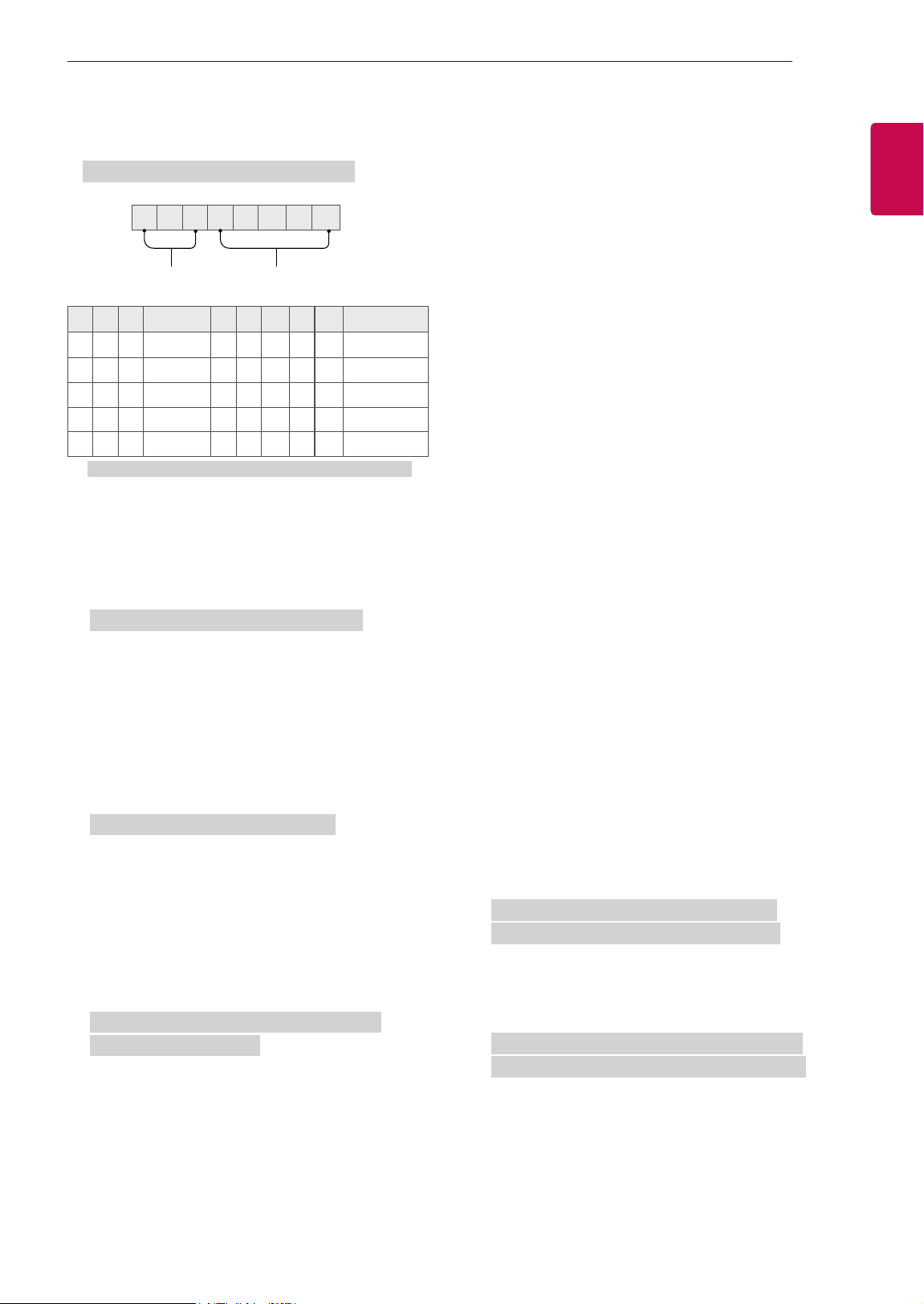
Transmission / Receiving Protocol
Transmission
[Command1][Command2][ ][Set ID][ ][Data][Cr]
[Command 1] : First command to control the TV. (j, k, m or x)
[Command 2] : Second command to control the TV.
[Set ID] : You can adjust the [Set ID] to choose desired monitor ID number in option menu.
Adjustment range in TV is 1 to 99. If [Set ID] value is selected to ‘0’, every connected set
can be controlled.
* [Set ID] is indicated as decimal (1 to 99) on menu and as Hexadecimal (0x00 to 0x63) on
transmission/receiving protocol.
[DATA] : To transmit command data (hexadecimal). Transmit ‘FF’ data to read status of command.
[Cr] : Carriage Return - ASCII code ‘0x0D’
[ ] : Space – ASCII code ‘0x20’
OK Acknowledgement
[Command2][ ][Set ID][ ][OK][Data][x]
* The set transmits ACK (acknowledgement) based on this format when receiving normal data. At this time,
if the data is data read mode, it indicates present status data. If the data is data write mode, it returns the
data of the PC computer.
Error Acknowledgement
[Command2][ ][Set ID][ ][NG][Data][x]
* The set transmits ACK (acknowledgement) based on this format when receiving abnormal data from
non-viable functions or communication errors.
Data 00: Illegal Code
Real data mapping (Hexadecimal b Decimal)
* When you enter the [data] in hexadecimal, refer to following conversion table.
* Channel Tune (ma) Command uses two-byte hexadecimal value([data]) to select channel number.
00 : Step 0 32 : Step 50 (Set ID 50) FE : Step 254
01 : Step 1 (Set ID 1) 33 : Step 51 (Set ID 51) FF : Step 255
... ... ...
0A : Step 10 (Set ID 10) 63 : Step 99 (Set ID 99) 01 00 : Step 256
... ... ...
0F : Step 15 (Set ID 15) C7 : Step 199 27 0E : Step 9998
10 : Step 16 (Set ID 16) C8 : Step 200 27 0F : Step 9999
... ... ...

7
ENGENGLISH
7
EXTERNAL CONTROL DEVICE SETUP
* Commands may work differently depending on model and signal.
01. Power (Command: k a)
► To control Power *On or Off of the set.
Transmission[k][a][ ][Set ID][ ][Data][Cr]
Data 00 : Power Off 01 : *Power On
Ack [a][ ][Set ID][ ][OK/NG][Data][x]
► To Show TV is Power On or *Off
Transmission [k][a][ ][Set ID][ ][FF][Cr]
Ack [a][ ][Set ID][ ][OK][Data][x]
* Similarly, if other functions transmit ‘FF’ data
based on this format, Acknowledgement feedback
presents status about each function.
02. Aspect Ratio (Command: k c)
(Main Picture Size)
► To adjust the screen format. (Main picture format)
You can also adjust the screen format using the
Aspect Ratio in the Q.MENU. or PICTURE menu.
Transmission [k][c][ ][Set ID][ ][Data][Cr]
Data 01 : Normal screen
(4:3)
02 : Wide screen
(16:9)
04 : Zoom
05 : Zoom 2
(Latin America
except Colombia
Only)
06 : Set by Program/
Original
07 : 14:9
(Europe, Colombia, Mid-East,
Asia except South Korea and
Japan)
09 : * Just Scan
0B : Full Wide
(Europe, Colombia, Mid-
East, Asia except South
Korea and Japan)
10 to 1F : Cinema Zoom 1 to 16
0c : 21:9 (Depending on model)
Ack [c][ ][Set ID][ ][OK/NG][Data][x]
* Using the PC input, you select either 16:9 or 4:3
screen aspect ratio.
* In DTV/HDMI/Component mode (high-definition),
Just Scan is available.
* Full wide mode may work differently based on
model and is supported for DTV fully, and ATV,
AV partially.
03. Screen Mute (Command: k d)
► To select screen mute on/off.
Transmission [k][d][ ][Set ID][ ][Data][Cr]
Data 00 : Screen mute off (Picture on)
Video mute off
01 : Screen mute on (Picture off)
10 : Video mute on
Ack [d][ ][Set ID][ ][OK/NG][Data][x]
* In case of video mute on only, TV will display On
Screen Display(OSD). But, in case of Screen mute
on, TV will not display OSD.
04. Volume Mute (Command: k e)
► To control volume mute on/off.
You can also adjust mute using the MUTE button
on remote control.
Transmission [k][e][ ][Set ID][ ][Data][Cr]
Data 00 : Volume mute on (Volume off)
01 : Volume mute off (Volume on)
Ack [e][ ][Set ID][ ][OK/NG][Data][x]
05. Volume Control (Command: k f)
► To adjust volume.
You can also adjust volume with the volume
buttons on remote control.
Transmission [k][f][ ][Set ID][ ][Data][Cr]
Data Min : 00 to Max : 64
Ack [f][ ][Set ID][ ][OK/NG][Data][x]
06. Contrast (Command: k g)
► To adjust screen contrast.
You can also adjust contrast in the PICTURE
menu.
Transmission [k][g][ ][Set ID][ ][Data][Cr]
Data Min : 00 to Max : 64
Ack [g][ ][Set ID][ ][OK/NG][Data][x]
07. Brightness (Command: k h)
► To adjust screen brightness.
You can also adjust brightness in the PICTURE
menu.
Transmission [k][h][ ][Set ID][ ][Data][Cr]
Data Min : 00 to Max : 64
Ack [h][ ][Set ID][ ][OK/NG][Data][x]

8
ENG
ENGLISH
8
EXTERNAL CONTROL DEVICE SETUP
08. Color/Colour (Command: k i)
► To adjust the screen Color(Colour).
You can also adjust colour in the PICTURE menu.
Transmission [k][i][ ][Set ID][ ][Data][Cr]
Data Min : 00 to Max : 64
Ack [i][ ][Set ID][ ][OK/NG][Data][x]
09. Tint (Command: k j)
► To adjust the screen tint.
You can also adjust tint in the PICTURE menu.
Transmission [k][j][ ][Set ID][ ][Data][Cr]
Data Red : 00 to Green : 64
Ack [j][ ][Set ID][ ][OK/NG][Data][x]
10. Sharpness (Command: k k)
► To adjust the screen sharpness.
You can also adjust sharpness in the PICTURE
menu.
Transmission [k][k][ ][Set ID][ ][Data][Cr]
Data Min : 00 to Max : 32
Ack [k][ ][Set ID][ ][OK/NG][Data][x]
11. OSD Select (Command: k l)
► To select OSD (On Screen Display) on/off when
controlling remotely.
Transmission [k][l][ ][Set ID][ ][Data][Cr]
Data 00 : OSD off 01 : OSD on
Ack [l][ ][Set ID][ ][OK/NG][Data][x]
12. Remote control lock mode (Command: k m)
► To lock the front panel controls on the monitor and
remote control.
Transmission [k][m][ ][Set ID][ ][Data][Cr]
Data 00 : Lock off 01 : Lock on
Ack [m][ ][Set ID][ ][OK/NG][Data][x]
* If you are not using the remote control, use this
mode.
When main power is off & on (plug-off and plug-in,
after 20 - 30 seconds), external control lock is
released.
* In the standby mode (DC off by off timer or ‘ka’,
‘mc’ command), and if key lock is on, TV will not
turn on by power on key of IR & Local Key.
13. Treble (Command: k r)
► To adjust treble.
You can also adjust in the AUDIO menu.
Transmission [k][r][ ][Set ID][ ][Data][Cr]
Data Min : 00 to Max : 64
Ack [r][ ][Set ID][ ][OK/NG][Data][x]
* (Depending on model)
14. Bass (Command: k s)
► To adjust Bass.
You can also adjust in the AUDIO menu.
Transmission [k][s][ ][Set ID][ ][Data][Cr]
Data Min : 00 to Max : 64
Ack [s][ ][Set ID][ ][OK/NG][Data][x]
* (Depending on model)
15. Balance (Command: k t)
► To adjust balance.
You can also adjust balance in the AUDIO menu.
Transmission [k][t][ ][Set ID][ ][Data][Cr]
Data Min : 00 to Max : 64
Ack [t][ ][Set ID][ ][OK/NG][Data][x]
16. Color(Colour) Temperature (Command: x u)
► To adjust colour temperature. You can also adjust
Color(Colour) Temperature in the PICTURE menu.
Transmission [x][u][ ][Set ID][ ][Data][Cr]
Data Min : 00 to Max : 64
Ack [u][ ][Set ID][ ][OK/NG][Data][x]
17. ISM Method (Command: j p) (Only Plasma TV)
► To control the ISM method. You can also adjust
ISM Method in OPTION menu.
Transmission [j][p][ ][Set ID][ ][Data][Cr]
Data Min : 02: Orbiter
08: Normal
20: Color(Colour) Wash
Ack [p][ ][Set ID][ ][OK/NG][Data][x]
9
ENGENGLISH
9
EXTERNAL CONTROL DEVICE SETUP
18. Equalizer (Command : j v)
► Adjust EQ of the set.
Transmission [j][v][ ][Set ID][ ][Data][Cr]
0 0 0 0 0 0 0 0
MSB
Frequency Data
LSB
7 6 5
Frequency
4 3 2 1 0 Step
0 0 0
1st Band
0 0 0 0 0
0(decimal)
0 0 1
2nd Band
0 0 0 0 1
1(decimal)
0 1 0
3rd Band
... ... ... ... ...
...
0 1 1
4th Band
1 0 0 1 1
19(decimal)
1 0 0
5th Band
1 0 1 0 1
20(decimal)
Acknowledgement [v][ ][Set ID][ ][OK/NG][Data][x]
* It depends on model, and can adjust when sound
mode is EQ adjustable value.
19. Energy Saving (Command: j q)
► To reduce the power consumption of the TV. You
can also adjust Energy Saving in PICTURE menu.
Transmission [j][q][ ][Set ID][ ][Data][Cr]
Data
00 : Off
01 : Minimum
02 : Medium
03 : Maximum
04 : Auto (For LCD TV / LED TV) /
Intelligent sensor (For PDP TV)
05 : Screen off
* (Depending on model)
Ack [q][ ][Set ID][ ][OK/NG][Data][x]
20. Tune Command (Command: m a)
* This command may work differently depending on
model and signal.
• For Europe, Mid-East, Colombia, Asia except
South Korea and Japan Model
► Select channel to following physical number.
Transmission [m][a][ ][Set ID][ ][Data 00][ ]
[Data 01][ ][Data 02][Cr]
* Analog Antenna/Cable
[Data 00][Data 01] Channel Data
Data 00 : High byte channel data
Data 01 : Low byte channel data
- 00 00 ~ 00 C7 (Decimal : 0 ~ 199)
Data 02 : Input Source (Analog)
- 00 : Antenna TV (ATV)
- 80 : Cable TV (CATV)
* Digital Antenna/Cable/Satellite
[Data 00][Data 01]: Channel Data
Data 00 : High Channel data
Data 01 : Low Channel data
- 00 00 ~ 27 0F (Decimal: 0 ~ 9999)
Data 02 : Input Source (Digital)
- 10 : Antenna TV (DTV)
- 20 : Antenna Radio (Radio)
- 40 : Satellite TV (SDTV)
- 50 : Satellite Radio (S-Radio)
- 90 : Cable TV (CADTV)
- a0 : Cable Radio (CA-Radio)
* Tune Command Examples:
1. Tune to the Analog antenna (PAL) Channel 10.
Set ID = All = 00
Data 00 & 01 = Channel Data is 10 = 00 0a
Data 02 = Analog Antenna TV = 00
Result = ma 00 00 0a 00
2. Tune to the digital antenna (DVB-T) Channel 01.
Set ID = All = 00
Data 00 & 01 = Channel Data is 1 = 00 01
Data 02 = Digital Antenna TV = 10
Result = ma 00 00 01 10
3. Tune to the satellite (DVB-S) Channel 1000.
Set ID = All = 00
Data 00 & 01 = Channel Data is 1000 = 03 E8
Data 02 = Digital Satellite TV = 40
Result = ma 00 03 E8 40
Ack [a][ ][Set ID][ ][OK][Data 00][Data 01]
[Data 02][x][a][ ][Set ID][ ][NG][Data 00][x]
• For South Korea, North/Latin America except
Colombia Model
► To tune channel to following physical/major/minor
number.
Transmission [m][a][ ][0][ ][Data00][ ][Data01]
[ ][Data02][ ][Data03][ ][Data04][ ][Data05][Cr]
Digital channels have a Physical, Major, and Minor
channel number. The Physical number is the actual
digital channel number, the Major is the number that
the channel should be mapped to, and the Minor is
the sub-channel. Since the ATSC tuner automatically
maps the channel from the Major / Minor number,
the Physical number is not required when sending a
command in Digital.

10
ENG
ENGLISH
10
EXTERNAL CONTROL DEVICE SETUP
* Analog Antenna/Cable
Data 00 : Physical Channel Number
- Antenna (ATV) : 02~45 (Decimal: 2 ~ 69)
- Cable (CATV) : 01, 0E~7D (Decimal : 1, 14~125)
[Data 01 ~ 04]: Major/Minor Channel Number
Data 01 & 02: xx (Don't care)
Data 03 & 04: xx (Don't care)
Data 05: Input Source (Analog)
- 00 : Antenna TV (ATV)
- 01 : Cable TV (CATV)
* Digital Antenna/Cable
Data 00 : xx (Don't care)
[Data 01][Data 02]: Major Channel Number
Data 01 : High byte Channel Data
Data 02 : Low byte Channel Data
- 00 01 ~ 27 0F (Decimal: 1 ~ 9999)
[Data 03][Data 04]: Minor Channel Number
Data 03 : High byte Channel Data
Data 04 : Low byte Channel Data
Data 05 : Input Source (Digital)
- 02 : Antenna TV (DTV) – Use Physical Channel
Number
- 06 : Cable TV (CADTV) – Use Physical Channel
Number
- 22 : Antenna TV (DTV) – Don’t Use Physical
Channel Number
- 26 : Cable TV (CADTV) - Don’t Use Physical
Channel Number
- 46 : Cable TV (CADTV) – Use Physical/Major
Channel Number Only (One Part Channel)
- 66 : Cable TV (CADTV) – Use Major Channel
Number Only (One Part Channel)
- 0b : Cable DTV Plus – Use Physical Channel
Number
- 2b : Cable DTV Plus – Don’t Use Physical
Channel Number
- 4b : Cable DTV Plus – Use Physical/Major
Channel Number Only (One Part Channel)
- 6b : Cable DTV Plus – Use Major Channel
Number Only (One Part Channel)
Two bytes are available for each major and minor
channel data, but usually the low byte is used alone
(high byte is 0).
* Tune Command Examples:
1. Tune to the Analog cable (NTSC) channel 35.
Set ID = All = 00
Data 00 = Channel Data is 35 = 23
Data 01 & 02 = No Major = 00 00
Data 03 & 04 = No Minor = 00 00
Data 05 = Analog Cable TV = 01
Total = ma 00 23 00 00 00 00 01
2. Tune to the digital antenna (ATSC) channel 30-3.
Set ID = All = 00
Data 00 = Don’t know Physical = 00
Data 01 & 02 = Major is 30 = 00 1E
Data 03 & 04 = Minor is 3 = 00 03
Data 05 = Digital Antenna TV = 22
Total = ma 00 00 00 1E 00 03 22
Ack [a][ ][Set ID][ ][OK][Data 00][Data 01]
[Data 02][Data 03][Data 04][Data 05]
[x][a][ ][Set ID][ ][NG][Data 00][x]
• For Japan Model
► To tune channel to following physical/major/minor
number.
Transmission [m][a][ ][0][ ][Data00][ ][Data01]
[ ][Data02][ ][Data03][ ][Data04][ ][Data05][Cr]
* Digital Antenna/Satellite
Data 00: xx (Don't care)
[Data 01][Data 02]: Major Channel Number
Data 01: High byte Channel Data
Data 02: Low byte Channel Data
- 00 01 ~ 27 0F (Decimal: 1 ~ 9999)
[Data 03][Data 04]: Minor/Branch Channel Number
(Don’t care in Satellite)
Data 03: High byte Channel Data
Data 04: Low byte Channel Data
Data 05 : Input Source (Digital/Satellite for Japan)
- 02 : Antenna TV (DTV)
- 42 : Antenna TV (DTV) – Use Physical/Major
Channel Number Only (One Part Channel)
- 62 : Antenna TV (DTV) – Use Major Channel
Number Only (One Part Channel)
- 07 : BS (Broadcasting Satellite)
- 08 : CS1 (Communication Satellite 1)
- 09 : CS2 (Communication Satellite 2)
* Tune Command Examples:
1
Tune to the digital antenna (ISDB-T) channel 17-1
.
Set ID = All = 00
Data 00 = Don’t know Physical = 00
Data 01 & 02 = Major is 17 = 00 11
Data 03 & 04 = Minor/Branch is 1 = 00 01
Data 05 = Digital Antenna TV = 02
Total = ma 00 00 00 11 00 01 02

11
ENGENGLISH
11
EXTERNAL CONTROL DEVICE SETUP
2. Tune to the BS (ISDB-BS) channel 30.
Set ID = All = 00
Data 00 = Don’t know Physical = 00
Data 01 & 02 = Major is 30 = 00 1E
Data 03 & 04 = Don’t Care = 00 00
Data 05 = Digital BS TV = 07
Total = ma 00 00 00 1E 00 00 07
* This feature is varied based on the model.
Ack [a][ ][Set ID][ ][OK][Data 00][Data 01]
[Data 02][Data 03][Data 04][Data 05]
[x][a][ ][Set ID][ ][NG][Data 00][x]
21. Channel(Programme) Add/Del(Skip)
(Command: m b)
► To skip current channel(programme) for next time.
Transmission [m][b][ ][Set ID][ ][Data][Cr]
Data 00 : Del(ATSC,ISDB)/Skip(DVB) 01 : Add
Ack [b][ ][Set ID][ ][OK/NG][Data][x]
* Set the saved channel status to del(ATSC, ISDB)/
skip(DVB) or add.
22. Key (Command: m c)
► To send IR remote key code.
Transmission [m][c][ ][Set ID][ ][Data][Cr]
Data Key code - p.2.
Ack [c][ ][Set ID][ ][OK/NG][Data][x]
23. Control Backlight (Command: m g)
• For LCD TV / LED TV
► To control the backlight.
Transmission [m][g][ ][Set ID][ ][Data][Cr]
Data Min : 00 to Max : 64
Ack [g][ ][Set ID][ ][OK/NG][Data][x]
Control Panel Light (Command: m g)
• For Plasma TV
► To control the panel light.
Transmission [m][g][ ][Set ID][ ][Data][Cr]
Data Min : 00 to Max : 64
Ack [g][ ][Set ID][ ][OK/NG][Data][x]
24. Input select (Command: x b)
(Main Picture Input)
► To select input source for main picture.
Transmission [x][b][ ][Set ID][ ][Data][Cr]
Data
00 : DTV
02 : Satellite DTV
ISDB-BS (Japan)
03 : ISDB-CS1 (Japan)
04 : ISDB-CS2 (Japan)
11 : CATV
01 : CADTV
10 : ATV
20 : AV or AV1 21 : AV2
40 : Component1
60 : RGB
41 : Component2
90 : HDMI1
92 : HDMI3
91 : HDMI2
93 : HDMI4
Ack [b][ ][Set ID][ ][OK/NG][Data][x]
* This function depends on model and signal.
25. 3D(Command: x t) (only 3D models)
(Depending on model)
► To change 3D mode for TV.
Transmission [x][t][ ][Set ID][ ][Data 00][ ][Data 01]
[ ][Data 02][ ][Data 03][Cr]
* (Depending on model)
Data Structure
[Data 00] 00 : 3D On
01 : 3D Off
02 : 3D to 2D
03 : 2D to 3D
[Data 01] 00 : Top and Bottom
01 : Side by Side
02 : Check Board
03 : Frame Sequential
04 : Column interleaving
05 : Row interleaving
[Data 02] 00 : Right to Left
01 : Left to Right
[Data 03] 3D Effect(3D Depth): Min : 00 - Max : 14
(*transmit by Hexadecimal code)
12
ENG
ENGLISH
12
EXTERNAL CONTROL DEVICE SETUP
* [Data 02], [Data 03] functions depend on model
and signal.
* If [Data 00] is 00 (3D On), [Data 03] has no
meaning.
* If [Data 00] is 01 (3D off) or 02 (3D to 2D), [Data
01], [Data 02] and [Data 03] have no meaning.
* If [Data 00] is 03 (2D to 3D), [Data 01] and
[Data 02] have no meaning.
* If [Data 00] is 00 (3D On) or 03 (2D to 3D), [Data
03] works when 3D Mode (Genre) is manual only.
* All 3D pattern options ([Data 01]) may not be
available according to broadcasting/video signal.
[Data 00] [Data 01] [Data 02] [Data 03]
00 O O O
01 X X X
02 X X X
03 X O O
X : don’t care
Ack [t][ ][Set ID][ ][OK][Data00][Data01][Data02]
[Data03][x]
[t][ ][Set ID][ ][NG][Data00][x]
26. Extended 3D(Command: x v) (only 3D models)
(Depending on model)
► To change 3D option for TV.
Transmission [x][v][ ][Set ID][ ][Data 00][ ]
[Data 01][Cr]
[Data 00] 3D option
00 : 3D Picture Correction
01 : 3D Depth (3D Mode is Manual Only)
02 : 3D Viewpoint
06 : 3D Color Correction
07 : 3D Sound Zooming
08 : Normal Image View
09 : 3D Mode (Genre)
[Data 01] It has own range for each 3D option
determined by [Data 00].
1) When [Data 00] is 00
00 : Right to Left
01 : Left to Right
2) When [Data 00] is 01, 02
Data Min: 0 - Max: 14 (*transmit by Hexadecimal
code)
Data value range(0 - 20) converts Viewpoint range
(-10 - +10) automatically (Depending on model)
* This option works when 3D Mode (Genre) is manual
only.
3) When [Data 00] is 06, 07
00 : Off
01 : On
4) When [Data 00] is 08
00 : Revert to 3D video from 3D-to-2D
converted 2D video
01 : Change 3D video to 2D video, except
2D-to-3D video
* If conversion condition doesn’t meet, command is
treated as NG.
5) When [Data 00] is 09
00 : Standard
02 : Cinema
04 : Manual
01 : Sport
03 : Extreme
05 : Auto
Ack [v][ ][Set ID][ ][OK][Data00][Data01][x]
[v][ ][Set ID][ ][NG][Data00][x]
27. Auto Configure (Command: j u)
(Depending on model)
► To adjust picture position and minimize image
shaking automatically. It works only in RGB (PC)
mode.
Transmission [j][u][ ][Set ID][ ][Data][Cr]
Data 01 : To set Auto Configure
Ack [u][ ][Set ID][ ][OK/NG][Data][x]