BRM 2788/3588
OWNER’S MANUAL
* This item is for consumer use only and it is not meant for commercial use.
Cardio Dual Trainer
- -
For use under U.S. Patent numbers 6159132, D459773, D438264
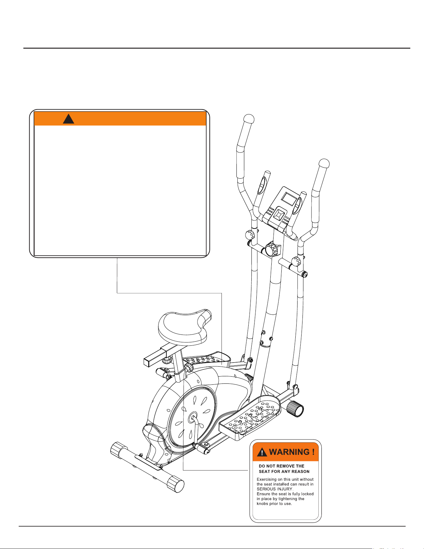
WARNING: SERIOUS INJURIES AND EVEN DEATH CAN OCCUR IF THE PROPER SAFETY PRECAUTIONS ARE NOT FOLLOWED.
The diagram below highlights and reviews many of the important Safety and Warning labels also found
on the unit. Please ensure any user of the unit familiarizes themselves with these Safety and Warning
guidelines before use.
PLEASE KEEP THESE INSTRUCTIONS FOR FUTURE USE & REFERENCE.
DO NOT DISCARD.
The use of this exercise equipment involves a RISK OF PHYSICAL INJURY as well as
property damage, which can be minimized by observing the following guidelines:
1. ALWAYS wear comf
ortable clothing
and shoes with good traction.
2. ALWAYS make sure all
nuts and bolts
are secured before use. TIGHTEN
PEDAL HINGE BOLTS EVERY 30
DAYS.
3. STOP EXE
RCISING if you become
diz
zy, nauseous, have irregular
heartbeats or breat
hing difficulties.
Contact your physician imme
diately.
4. ALWAYS keep a large mat under the
Equipment to prot
ect the floor or carpet.
5. ALWAYS use your Equipment in a
warm, dry, leve
l well-lit and ventilated
indoor area.
7. A
LWAYS keep
your Equipment clean
and free of dust,
moisture, debris and
loose objects.
8. NEVER use the
Equipment if you are
injured or have a physical condition
that impairs your balance. DO NOT
exercise under the influence of
medication or alcohol.
9. NEVER allow small children or pets to
approach the Equipment. It is not a
toy.
10. NEVER use the Equipment if you
exceed its weight limit of 250 lbs.
11. NEVER use the E
quipment if it does
not function properly.
6. ALWAYS keep body and clothing free
and clear of all moving parts.
W A R N I N G !
!
BRM 2788/3588 Page 1
General Information
Warranty
Body Flex Sports warrants your product for
a period of 1 year for the frame and 90 days
on all parts if the item is used for the intended
purpose, properly maintained and not used
commercially. Any alterations or incorrect
assembly of the product will void this warranty.
Proof of purchase must be presented for any
warranty validation (no exceptions). This
warranty applies to the original purchaser only
and is not transferable.
This warranty does not cover abuse or defects
caused during use, storage or assembly.
During the warranty period, Body Flex Sports
reserves the right to:
a). provide replacement parts to the
purchaser in an effort to repair the item.
b). repair the product returned to our
warehouse (at the purchaser’s cost).
c). replace the product if neither of the two
previously mentioned actions effect repair.
This warranty does not cover normal wear and
tear on upholstery.
Questions
If you have any questions concerning the
assembly of your item or if any parts are
missing, please DO NOT RETURN THE
ITEM TO THE STORE OR CONTACT THE
RETAILER. Our dedicated customer service
staff can help you with any questions you may
have regarding the assembly of this unit and
can also mail you replacement parts.
Customer Support
Customer Support is open 9:00 a.m. to 5:00
p.m. (Pacific Time) Monday through Friday.
Please contact us by any of the following
means.
Body Flex Sports, Inc.
21717 Ferrero Parkway, Walnut, CA 91789
Telephone: (888) 266 - 6789
Fax: (909) 598 - 6707
Email: info@bodyflexsports.com
Safety
Before you undertake any exercise program,
please be sure to consult with your doctor.
Frequent strenuous exercise should be
approved by your doctor and proper use
of your product is essential. Excessive or incorrect
training may result to health injuries. Please read
this manual carefully before commencing the
assembly of your product or starting to exercise.
• Please keep all children away from this item
when in use. Do not allow children to climb or
play on them when they are not in use.
• Supervise teenagers while they use this unit.
• For your own safety, always ensure that there
is at least 3 feet of free space in all directions
around your product while you are exercising.
• Regularly check to see that all nuts, bolts and
fittings are securely tightened. Periodically
check all moving parts for obvious signs of
wear or damage.
• Clean only with a damp cloth, do not use
solvent cleaners. If you are in any doubt, do
not use your product; contact CUSTOMER
SUPPORT.
• Before use, always ensure that your product
is positioned on a solid, flat surface. If
necessary, use a rubber mat underneath to
reduce the possibility of slipping.
•
Always wear appropriate clothing and
footwear such as training shoes when
exercising. Do not wear loose clothing that
could become caught in moving parts during
exercise.
• Do not use this unit if it is not functioning
properly or if it is not fully assembled.
• Do not use this unit for commercial purposes.
This unit is for home use only.
Storage and Use
Your product is intended for use in clean
dry conditions. You should avoid storage in
excessively cold or damp places as this may
lead to corrosion and other related problems.
Weight Limit
Your product is suitable for users weighing:
250 pounds or less.
• Before use, you must read and understand all
instructions & warnings stated in this Owner’s
Manual as well as posted on the equipment.
• It is the facility owner’s responsibility to properly
instruct users on the proper operation of the
equipment and to warn them of the potential
hazards.
• If at any time during exercise you feel faint, dizzy
or experience pain, stop and consult your
physician.
Assembling Tools
- Ruler with both metric and English measurements
- 2 x Adjustable Wrenches
- 1 x Philips (”Crosshead”) Screw Driver
•
Any adjustment devices that could interfere with
the user's movement on this unit should not be
left projecting.
BRM 2788/3588
Page 2
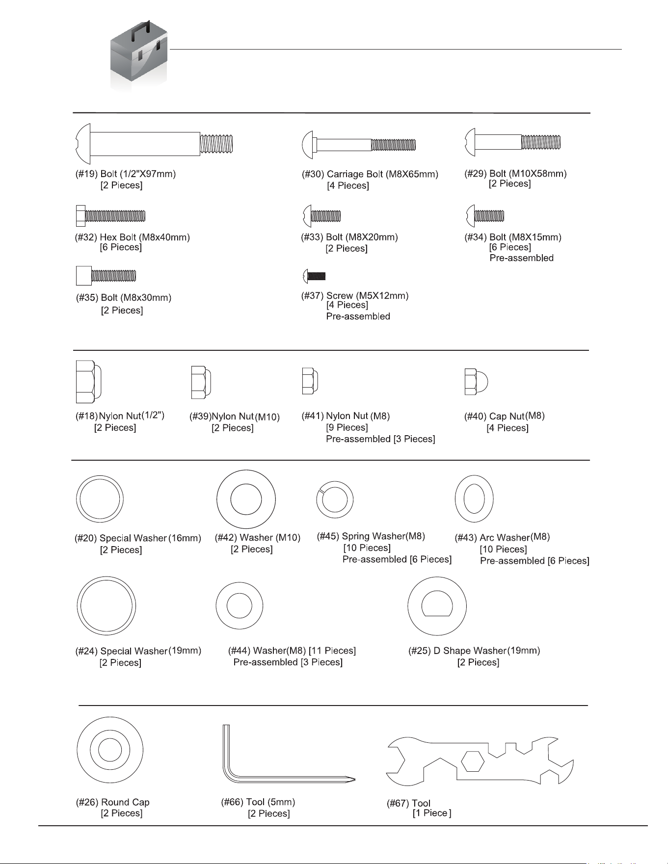
Hardware List
The following hardware is used to assemble your unit. Please take a moment to familiarize yourself with these
items. Please note some of this hardware is already pre-assembled on the machine. Do not be alarmed if you
see parts on this page that are not included in your hardware packet
Bolt
Nut
Washer
Others
Page 3 BRM 2788/3588
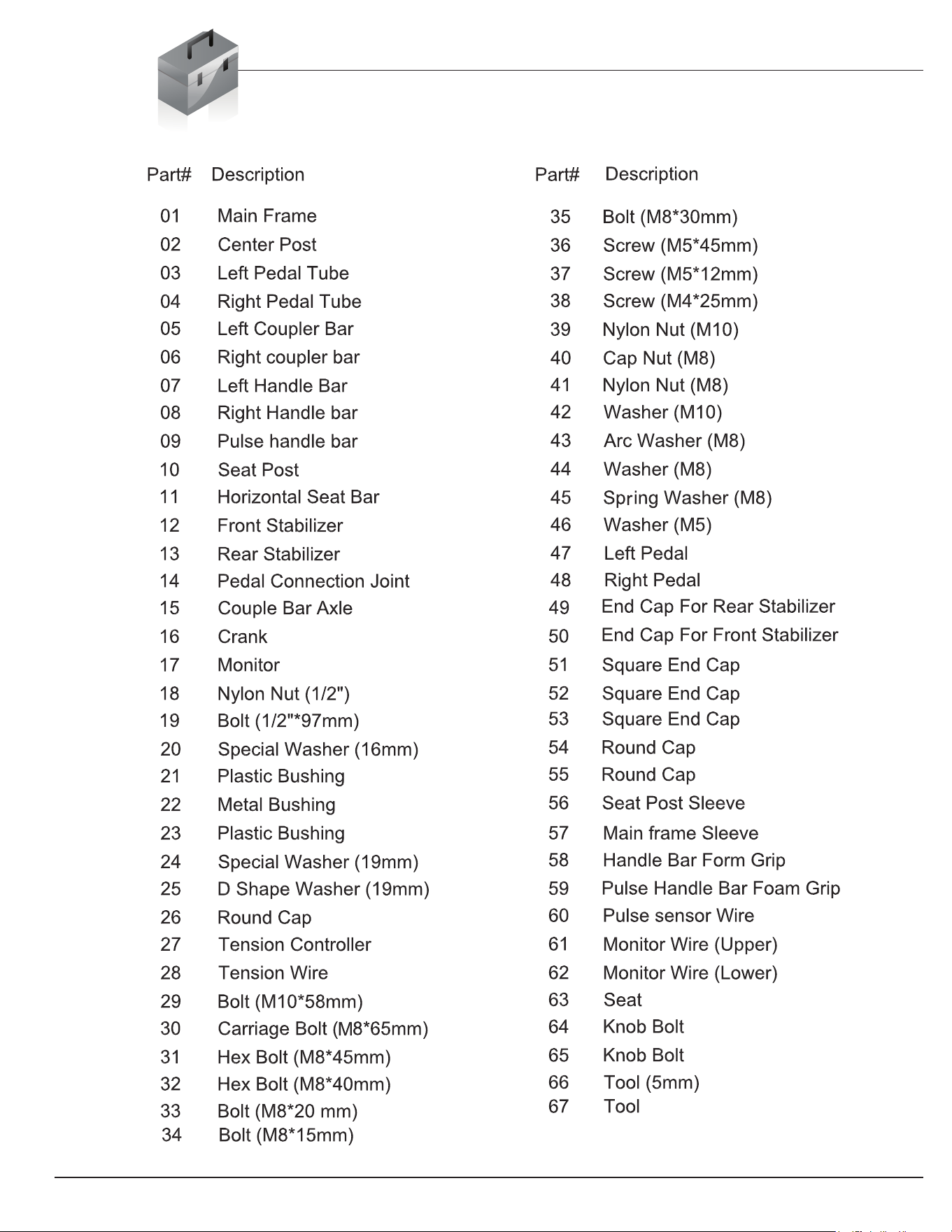
Parts Listing
The following parts list describes all of the parts illustrated on the
exploded diagram on the following page. Please note, most of
these parts are already pre-assembled on your unit.
Page 4
BRM 2788/3588
Page 5
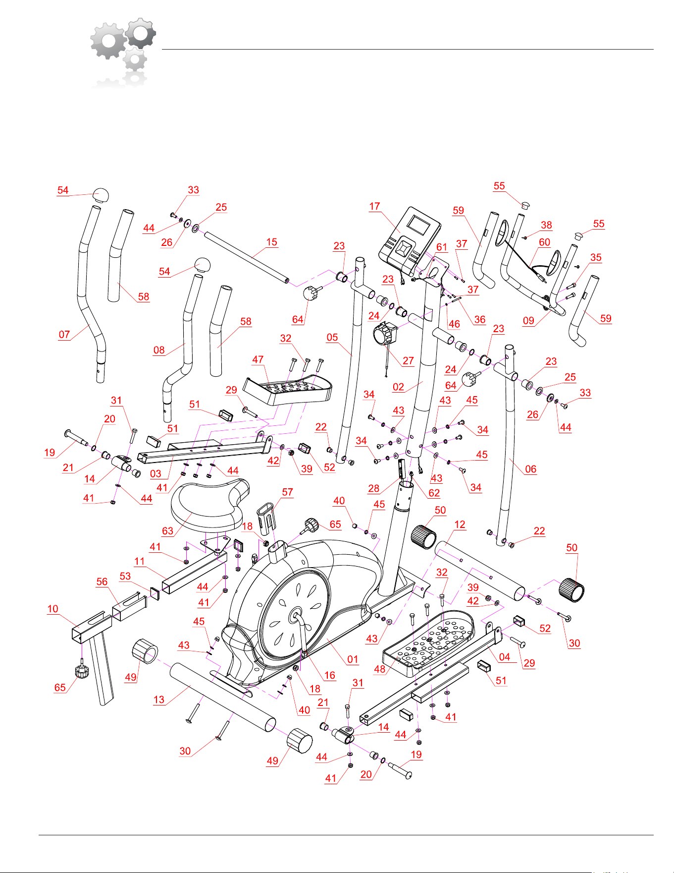
Exploded Diagram
The following diagram is provided to help you familiarize yourself with the parts and
hardware that will be used during the assembly process. Please note that not all of the
parts and hardware you see here will be used while you are assembling the machine
because some of these items are already pre-installed. Please continue to the next
page to begin the assembly process and use this page only as a reference guide for
parts and hardware.
BRM 2788/3588
Page 6
Make sure these two wires are accessible and exposed (as shown)
before proceeding to the next step. If they have fallen
inside the tube, use a bent wire to “fish” them out.
Spinning
End Caps
Height Adjustable
End Caps
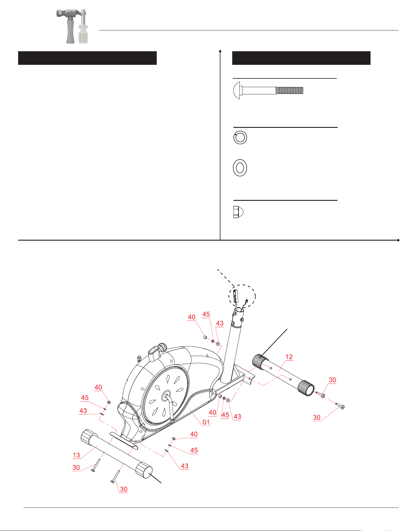
Assemb l y S t e p 1
With the help of an assistant, attach the Front Stabilizer (#12)
to the front of the Main Frame (#01). Insert two Carriage Bolts
(#30) through the Front Stabilizer (#12) followed by the front
of the Main Frame (#01). Secure them together using two Arc
Washers (#43), two Spring Washers (#45) and two Cap Nuts
(#40). Now attach the Rear Stabilizer (#13) to the rear of the
Main Frame (#01). Insert two Carriage Bolts (#30) through the
Rear Stabilizer (#13) followed by the rear of the Main Frame
(#01). Secure them together using two Arc Washers (#43), two
Spring Washers (#45) and two Cap Nuts (#40).
Please Note that the Front Stabilizer (#12) has end caps that
spin for ease of relocating the unit and the Rear Stabilizer (#13)
has height adjustable end caps for leveling of the unit.
Hardware Required
#30. Carriage Bolt (M8x65 mm
)
[4 Pieces]
Washer
#43. Arc Washer (M8)
[4 Pieces]
#45. Spring Washer (M8)
[4 Pieces]
Nut
#40. Cap Nut
(M8) [4 Pieces]
Bolt
Assembly Instructions
BRM 2788/3588
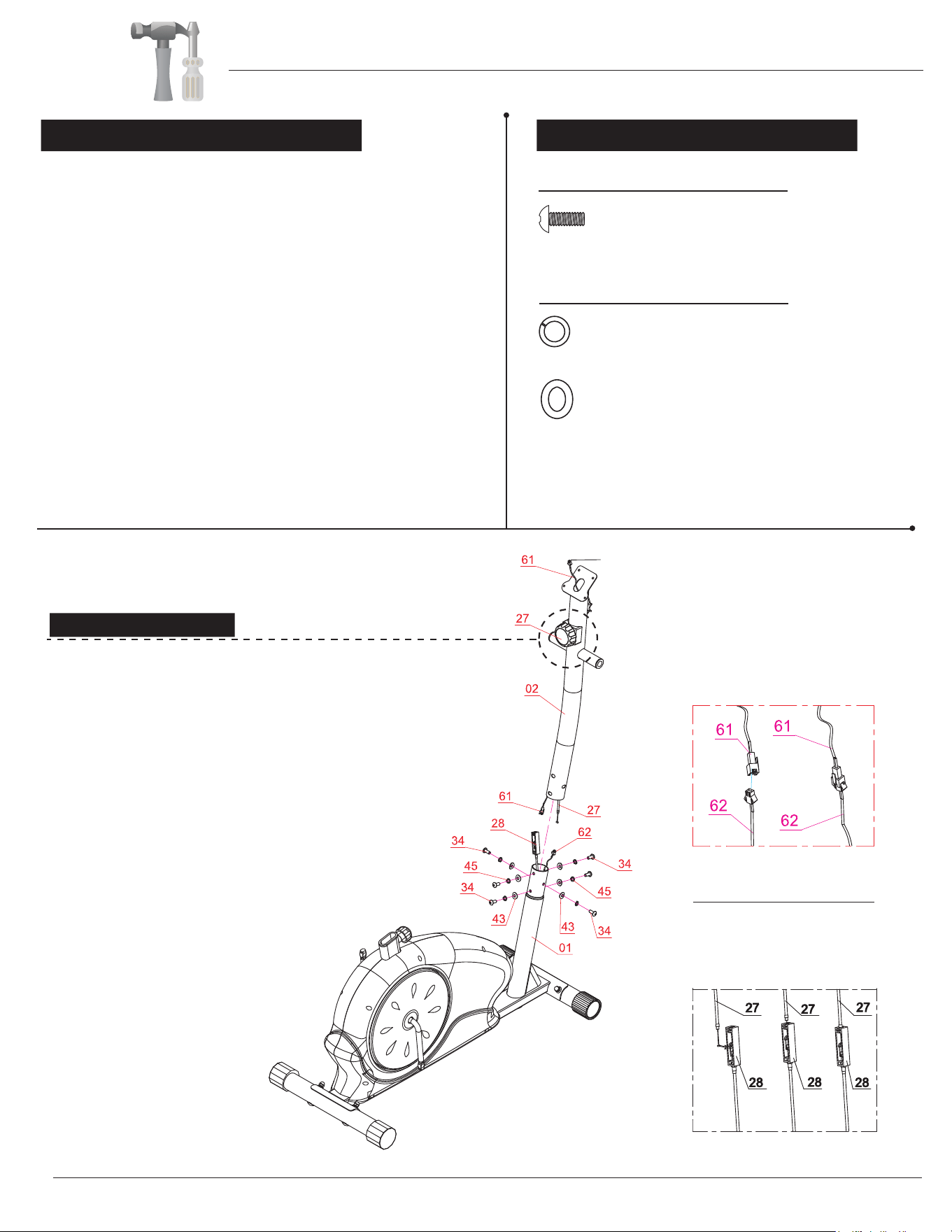
A s s e m b l y S t e p 2
Remove the Bolts (#34), Spring Washers (#45), and Arc
Washers (#43) that are pre-assembled on the Main Frame
(#01) and set them aside as they will be used later in this
step.
Connect the Monitor Wire (Upper) (#61) to the Monitor
Wire (Lower) (#62) and then follow the instructions in the
diagram below to connect the Tension Wire (#28). After
connecting the Tension Wire (#28) to the Tension
Controller (#27) slide the Center Post (#02) onto the Main
Frame (#01) and secure it using the Bolts (#34), Spring
Washers (#45), and Arc Washers (#43) that were previously
removed.
Hardware Required
#34. Bolt (M8x15 mm)
[6 Pieces]
Washer
#43. Arc Washer (M8)
[6 Pieces]
#45. Spring Washer (M8)
[6 Pieces]
Bolt
assembling the
Make sure this wire is exposed and accesible
before
Center post (#02).
Insert the tip of the Tension
controller (#27) wire into the Tension
wire (#28) head at an angle. Tilt the
Tension controller (#27) wire into the
crevice and then pull upward.
TENSION WIRE ASSEMBLY
Tension Adjustment
To increase the tension (+ higher level of intensity), turn the
Tension Controller (#27) in a clockwise direction.
To decrease the tension (- lower level of intensity), turn the
Tension Controller (#27) in a counter-clockwise direction.
"1" is the lowest level of tension (easiest level for workout);
"8" is the highest level of tension (most difficult level for workout).
55
40
1 2 3 4
55
40
1 2 3 4
STEP3:
Assembly Instructions
BRM 2788/3588
Page 7
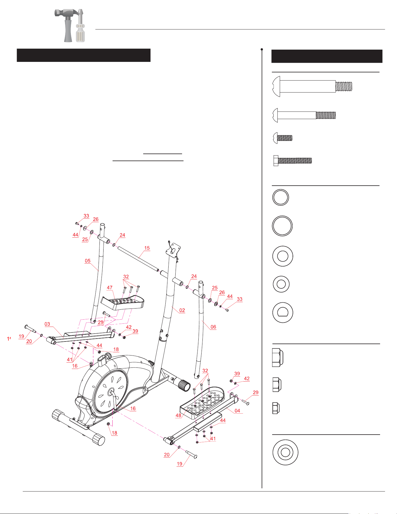
A s s e m b l y S t e p 3
Assembly Instructions
A s s e m b l y S t e p 3
Align and attach the Pedal Connection Joint (#14) on the Left Pedal Tube
(#03) to the left Crank (#16). Insert a Bolt (#19) through a Special Washer (#20)
followed by Pedal Connection Joint (#14) and Crank (#16). Screw the Bolt
(#19) tightly into the Crank (#16) by turning CLOCKWISE and then secure it with
the Nylon Nut (#18) by turning it COUNTERCLOCKWISE. Align and attach the
Left Coupler Bar (#05) to the Left Pedal Tube (#03). Secure them together using
a
Bolt (#29), Washer (#42) and Nylon Nut (#39). Attach the Left Pedal (#47)
to
the Left Pedal Tube (#03) and secure them together using three Hex Bolts (#32),
three Washers (#44) and three Nylon Nuts (#41). Repeat this process on the
other side with the Right Pedal Tube (#04) and Right Coupler Bar (#06).
Hardware Required
#19. Bolt (1/2”x97 mm)
[2 Pieces]
#29. Bolt (M10x58 mm)
[2 Pieces]
#32. Hex Bolt (M8x40 mm)
[6 Pieces]
#33. Bolt (M8x20 mm)
[2 Pieces]
Washer
#42. Washer (M10)
[2 Pieces]
#25. D Shape Washer (19 mm)
[2 Pieces]
#24. Special Washer (19
mm) [2 Pieces]
#20. Special Washer (16
mm) [2 Pieces]
#44. Washer (M8
)
[8 Pieces]
Nut
#18. Nylon Nut
(1/2”)
[2 Pieces]
#39. Nylon Nut
(M10)
[2 Pieces]
#41. Nylon Nut
(M8)
[6 Pieces]
Others
#26. Round Cap
[2 Pieces]
Bolt
Please refer to the diagram below and pay special attention to corresponding left & right side parts.
Misplacing parts during assembly will lead to incorrect assembly and may result in serious injur
y.
Slide the Couple Bar Axle (#15) through the center slot below the Tension
Controller (#27) knob on the Center Post (#02) and center it so it is evenly
distributed on the left/right sides. Next, slide one Special Washer (#24) on each side
then, followed by corresponding Left/Right Coupler Bar (#05/#06). Secure each
side with a D Shape Washer (#25), Round Cap (#26), Washer (#44), and a
Bolt (#33).
Page 8
BRM 2788/3588
Page 9
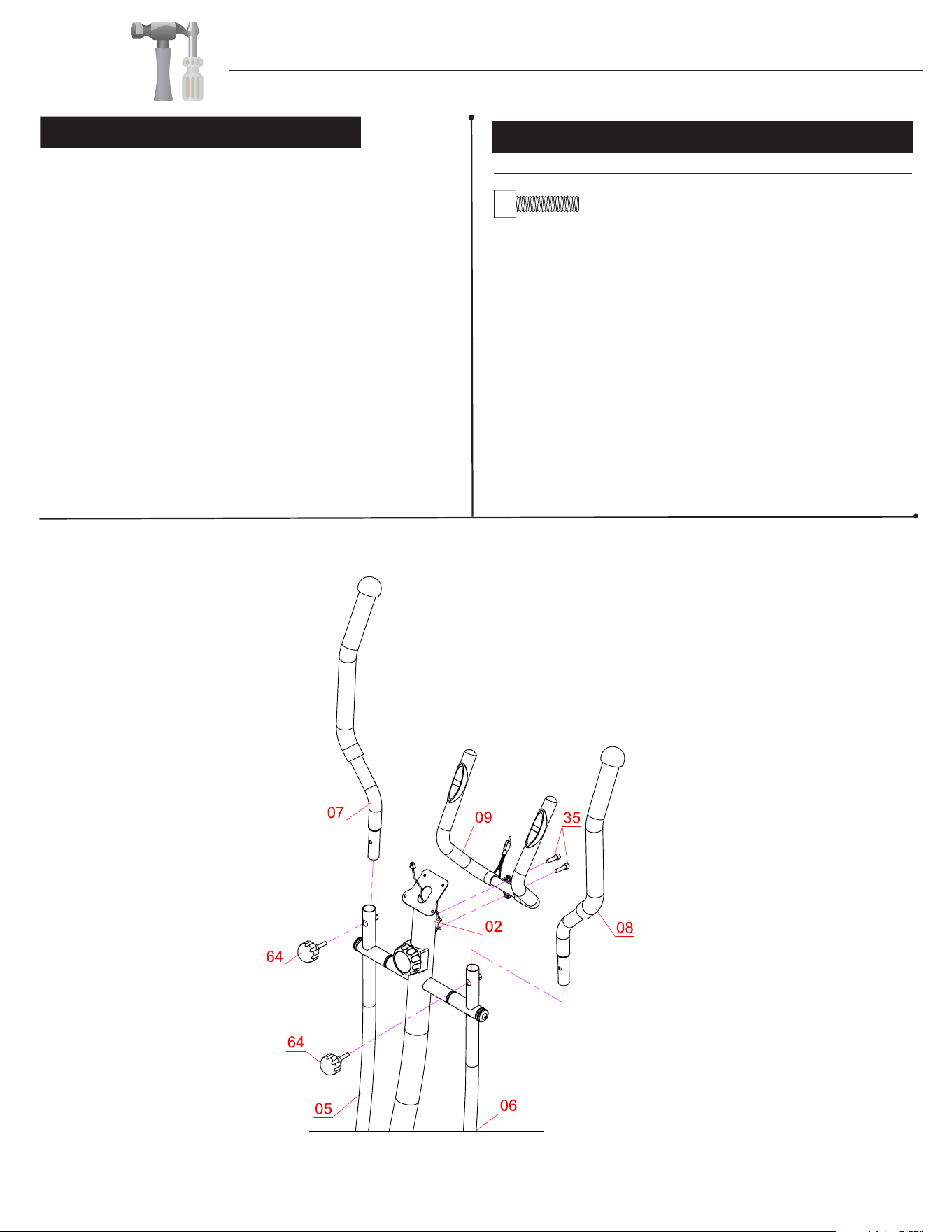
A s s e m b l y S t e p 4
Bolts
Insert the Left Handle Bar (#07) into the opening at the
top of the Left Coupler Bar (#05) and secure it using one
Knob Bolt (#64). Repeat this process on the other side
with the Right Handle Bar (#08) and Right Coupler Bar
(#06).
Align and attach the Pulse Handle Bar (#09) to the
bracket on the Center Post (#02) by securing with
two Bolts (#35).
#35. Bolt (M8x30 mm)
[2 Pieces]
If pre-assembled on unit, please remove both Knob
Bolts (#64).
Hardware Required
Assembly Instructions
BRM 2788/3588
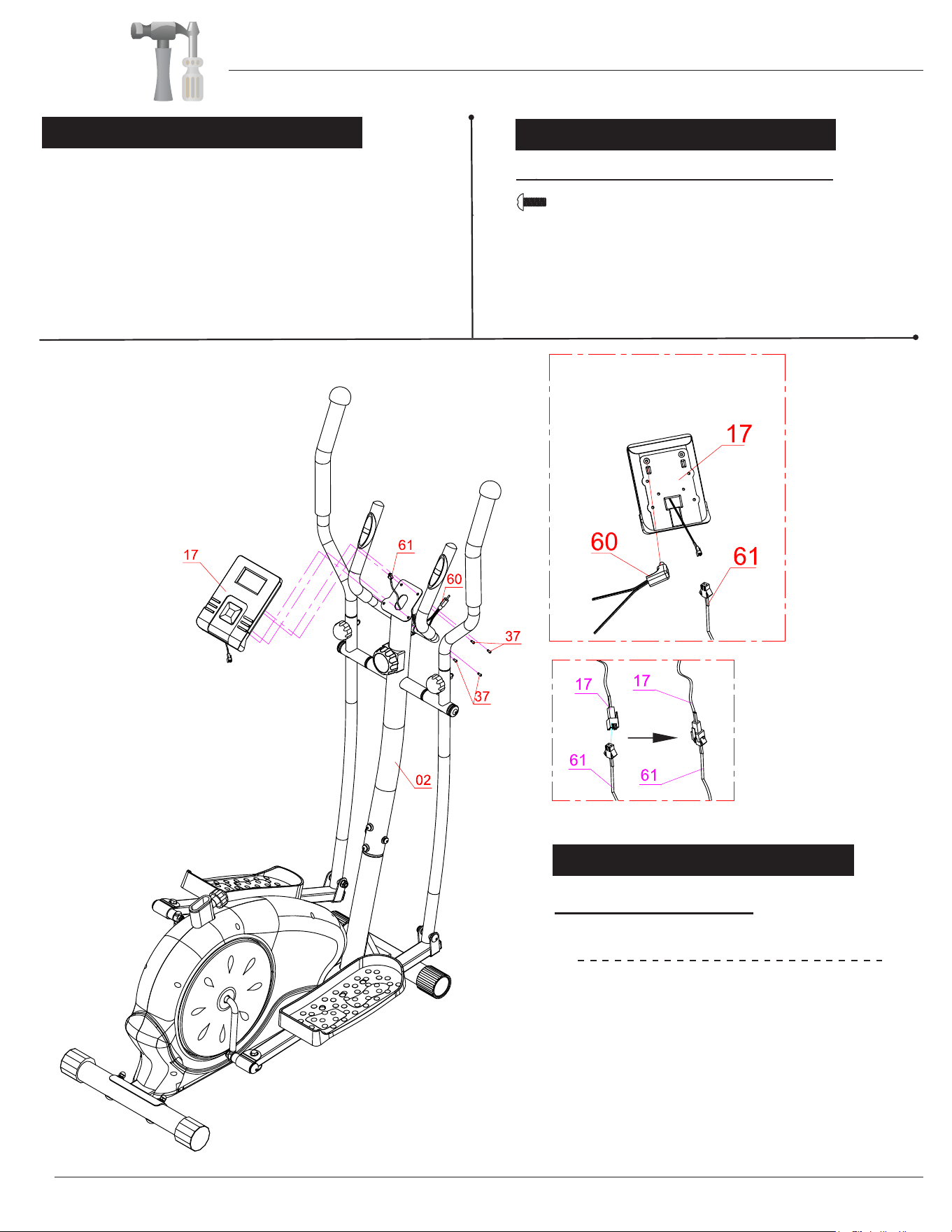
A s s e m b l y S t e p 5
Remove the Screws (#37) that are pre-assembled on
back of the Monitor (#17) and set them them aside as
they will be used shortly in this step. Connect the
Wire (Upper) (#61) to the Monitor (#17)
and connect the
Pulse Sensor Wire (#60) to the Monitor (#17). Secure
the Monitor (#17) to the bracket of the Center Post (#02)
using four Screws (#37) that were previously removed.
Hardware Required
#37. Screw (M5x12 mm)
[4 Pieces]
Screws
Assembly Instructions
After complete assembly: If the computer
is not picking up your hand pulse signal
(or you are getting inaccurate readings),
Please refer to our “Troubleshooting”
section on Page 15 for other troubleshoot
issues.
HAND PULSE SIGNAL
Troubleshooting
BRM 2788/3588
Page 1
0
Page 11
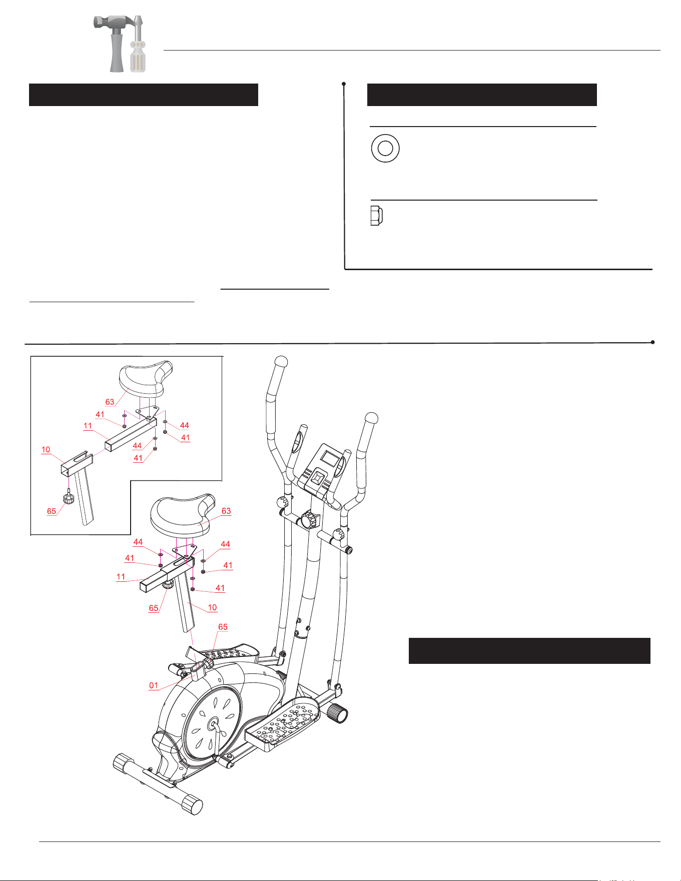
A s s e m b l y S t e p 6
Remove the three Washers (#44) and three Nylon Nuts
(#41) that are pre-assembled on the back of the Seat (#63)
and set them aside as they will be used later in this step.
Attach the Seat (#63) onto the Horizontal Seat Bar (#11)
and make sure that the Seat (#63) is pointing directly toward
the short end of it and then tighten with three Washers (#44)
and three Nylon Nuts (#41) that were previously removed.
The Knob Bolt (#65) can be loosened to adjust the distance
of the seat from the handle bars. Make sure to tighten the
knob after making any adjustment.
Insert the Seat Post (#10) into the mouth of the post that is
protruding from the Main Frame (#01) down a minimum of 4
on the Seat Post (#10) are facing the front before inserting.
Secure the Seat Post (#10) (now with Seat (#63) attached)
using the (previously removed) Knob Bolt (#65).
Hardware Required
Washer
#44. Washer (M8
)
[3 Pieces]
Nut
#41. Nylon Nut (M8) [3 Pieces]
W A R N I N G
Do not remove the Seat (#63) for any
reason after you have installed it.
Exercising on this unit without the Seat
(#63) can result in SERIOUS INJURY.
Ensure the seat is locked in place by
tightening the two knobs prior to use.
Assembly Instructions
If pre-assembled, remove the Knob Bolt (#65) on the mouth of
the Main Frame (#01).
The assembly process is now complete. However, for your own safety,
please make sure to read this entire Owner’s Manual which includes
safety instructions and warnings, as well as any safety/warning labels
affixed to the product before use.
For your safety, please visually and functionally inspect and test the unit
after assembly is complete.
inches to engage the lowest hole. Make sure the holes
BRM 2788/3588

SAFETY & WARNINGS
Page 12
Safety & Maintenance
• Make sure all nuts, bolts, and screws are tightened prior to use.
• Be sure that all adjustment locking devices and safety devices are properly engaged prior to use!
• Never over-tighten the above-mentioned devices and parts to avoid damage to the unit.
• Check for loose parts and components and make prope
r adjustments prior to use.
• Check to see if there are any tears or bends in the welding or metal prior to use. If tears or bends are found, do
NOT use the unit and contact our CUSTOMER SUPPORT.
• Extreme care must be taken to not allow your feet, fing
ers, hair, clothing, and/or any loose items to be snagged
into any portion of the bike when the unit is in motion. Failure to follow these instructions could result in serious
in
jury, including the loss of fingers.
• Always wait for the pedals and other moving parts (which can gain great momentum during riding) to come to a c
omplete stop before dismounting the unit to avoid serious injury.
• Please be aware that the pulse sensors and body
fat measurement tool are not medical devices;
the pulse sensors and body fat measurement tool
should not be used or applied for medical reasons.
• Do not use solvent cleaners. If in any doubt, do not use
your cleansing product; contact CUSTOMER SUPPORT
MAINTENANCE & CARE
• For any replacement warning labels, please contact our CUSTOMER SUPPORT at (888) 266-6789 or
(909) 598-9876, or mail in a written request to: Body Flex Sports, Inc. 21717 Ferrero Parkway, Walnut, CA 91789.
More detailed information about how to reach our CUSTOMER SUPPORT may be found on Page 2 of the Owner’s
Manual under the “CUSTOMER SUPPORT” section.
•
The specific Parts on your unit which may see possible signs of wear after prolonged use are listed as follows
(please check these parts before each use):
Seat (#63); Pedals (#47/#48); Handle Bars (#07/#08).
• Please review all safety instructions and warnings in this entire Owner’s Manual, as well as any safety/warning
labels affixed to the product before use.
1. Using one hand to hold Seat Post (#10) , unscrew Knob Bolt (#65) using the other hand.
2. Slide and adjust Seat Post (#10) to the desired hole setting to your preferred height.
3. Holding Seat Post (#10)
at this setting, re-insert/re-screw Knob Bolt(#65), ensuring it engages and fully inserts
through the holes of Main Frame (#01) and
Seat Post (#10). Please make sure to securely tighten Seat Post
4. Before sitting on the cycle, press down firmly and pull up slightly on the seat to make sure it is engaged and secure.
HOW TO ADJUST THE SEAT
NOTE: Always wait for the pedals and other moving parts (which can gain great momentum during riding)
to come to a complete stop before dismounting the unit to avoid serious injury.
1. To reduce speed on the bike, you may use the combinations of your feet on the Left/Right Pedals (#47/48)
and your hands on the Left/Right Handlebars (#07/08) to gently and safely apply counter-momentum.
2. Wait for the flywheel, handlebars, and pedals to come to a complete stop.
3. Now you may safely dismount the unit.
HOW TO (EMERGENCY) STOP
NOTE: To safely move, transport, and/or store the unit, please seek the help of capable assistants (minimum 2
people total).
1. Position one person on each side of the bike (one on the left, and one on the right).
2. Have each person use the hand closest to the Seat (#63) to grip it. Then, grip the other hand from underneath the
respective Left/Right Handlebars (#07/08). (These are the safest areas to avoid injury during this process.)
3. Have both people simultaneously lift the unit to move/transport the unit to the desired area.
HOW TO MOVE/TRANSPORT THE BIKE FOR STORAGE
(#10) but not over-tighten.
BRM 2788/3588
Computer Operation
Page 13
BRM 2788/3588
*IMPORTANT NOTE :
Please remember that the functions in this computer are only meant to be tools to
monitor your workout progress; they are not meant to provide medical information
or be used for medical purposes. Please consult a physician before beginning any
workout program.
SCAN : The monitor will then rotate displaying through the following functions: time,speed,distance,
calories and odometer. Each function will display for 5 seconds.
TIME : Displays the total amount of time using the machine.
SPEED : Displays current speed.
DISTANCE : Displays the distance traveled.
CALORIES : Displays the amount of calories burned.
PULSE (if equipped) : Hold the pulse sensor and read your heart rate per minute.
ODOMETER (if equipped): Displays total accumulated distance.
1.
2.
3. The monitor will auto-power on when exercise and/or motion input is detected.
4. The monitor will automatically start calculating when you start to exercise and will stop calculating when you stop
exercising for 4 minutes .
FUNCTIONS
NOTE
Operation Procedures
AUTO SCAN Every 6 seconds
TIME 00:00-99:59 min
SPEED Max 999.9 mi./H
CALORIES 0.0-999.9 KCal
DISTANCE 0.0-999.9 mi.
BATTERY TYPE 2 pcs of AAA
PULSE RATE 40-240 bpm
OPERATING TEMP 32°F - 104°F
STORAGE TEMP 14°F - 140°F
FUNCTIONS
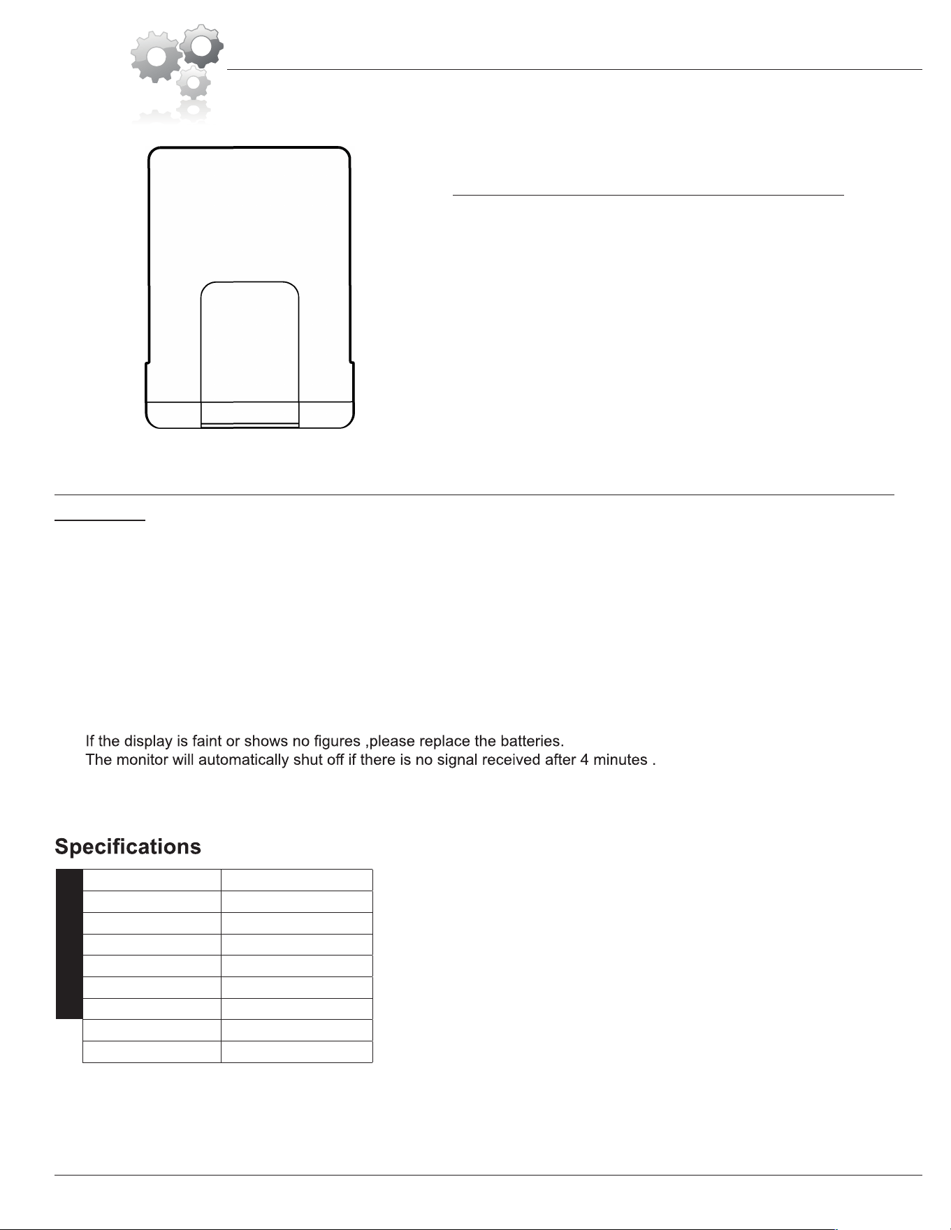
MODE :
Press this button to select the display function of your
choice.
RESET :
Hold MODE button for 3 seconds to reset all value to
zero.
Key Function
D
=
=��
�
=
=
Computer Operation
Page 1
4
BRM 2788/3588
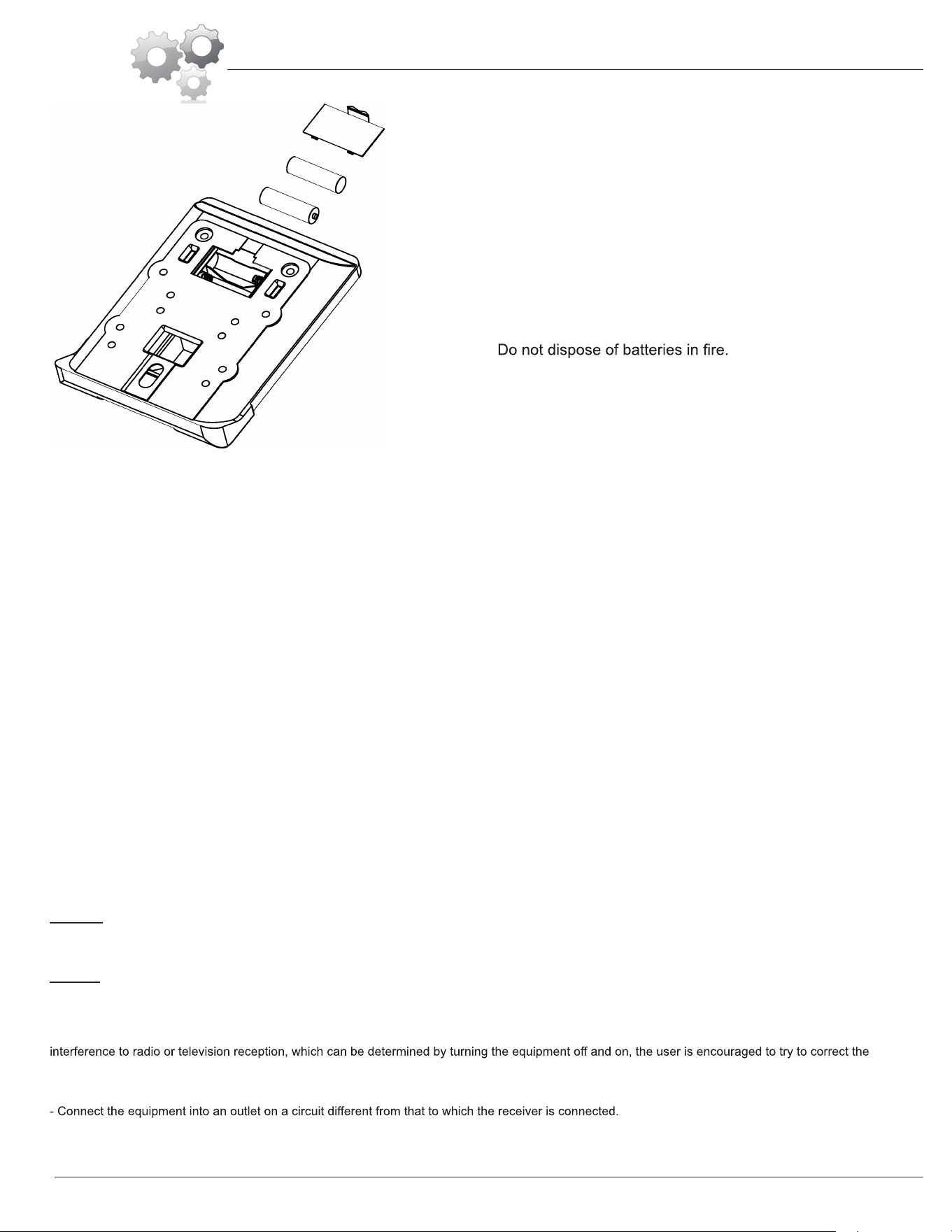
How To Install and Replace Batteries
1. Open the battery door on the back of the computer.
2. The computer operates on two AAA batteries (included).
Refer to the illustration to install or replace the batteries.
NOTE :
1. Do not mix a new battery with an old battery.
2. Use the same type of battery. Do not mix an alkaline
battery with another type of battery.
3. Rechargeable batteries are not recommended.
4. Battery disposal should be handled according to all state
and federal laws and regulations.
5.
NOTES (Regarding the Computer Monitor):
Warning: This device complies with Part 15 of the FCC Rules. Operation is subject to the following two conditions:
(1) This device may not cause harmful interference.
(2) This device must accept any interference received, including interference that may cause undesired operation.
Caution:
This equipment has been tested and found to comply with the limits for a Class B digital device, pursuant to part 15 of the FCC Rules.
These limits are designed to provide reasonable protection against harmful interference in a residential installation. This equipment generates, uses and
can radiate radio frequency energy and, if not installed and used in accordance with the instructions, may cause harmful interference to radio
communications. However, there is no guarantee that interference will not occur in a particular installation. If this equipment does cause harmful
interference by one or more of the following measures:
- Reorient or relocate the receiving antenna.
- Increase the separation between the equipment and receiver.
- Consult the dealer or an experienced radio/TV technician for help.

Troubleshooting
If the computer is not picking up your hand pulse signal (or you are getting
inaccurate readings), please adjust the following:
1. Slightly moisten/dampen the palms with water so the sensors can detect a
pulse signal.
2. Do not grip the sensors too tightly. Only moderate pressure need be applied.
Gripping the sensors too tightly restricts and seizes detection of your pulse.
3. Remove any rings or jewelry to prevent interference.
4. Check to ensure all pulse sensor wires are properly connected and are
not damaged.
You may need to refer to installation/assembly directions for the pulse sensor
wires in this manual.
If the computer is not displaying the CALORIES/DISTANCE/TIME/(ETC.) functions
(or you are getting inaccurate readings), please adjust the following:
1. Check to ensure all computer sensor wires are properly connected and are
not damaged.
You may need to refer to installation/assembly directions for the sensor wires
in this manual.
If the computer display is blank & not displaying any data (or does not appear to
power on), please adjust the following:
1. Check to ensure all sensor wires are all properly connected and are
not damaged.
2. Check to ensure the AC Adapter* or Batteries* are properly plugged in or
fully charged.
Troubleshoot Area
HAND PULSE SIGNAL
CALORIES/DISTANCE/
TIME/(ETC.)
COMPUTER Display
(AFTER COMPLETE ASSEMBLY)
Solution
*Please check your product manual to determine if your model uses either
1. an AC Adapter, or 2. Batteries to power your unit.
For your safety, please do not discard this Troubleshooting sheet or the Owner’s Manual,
and keep them in a place where you can easily access/refer to them at any time.
If you are still having any troubleshooting issues, please contact our Customer Support
for further assistance.
Page 15
BRM 2788/3588
Warm-Up Instructions
BRM 2788/3588
Page 16
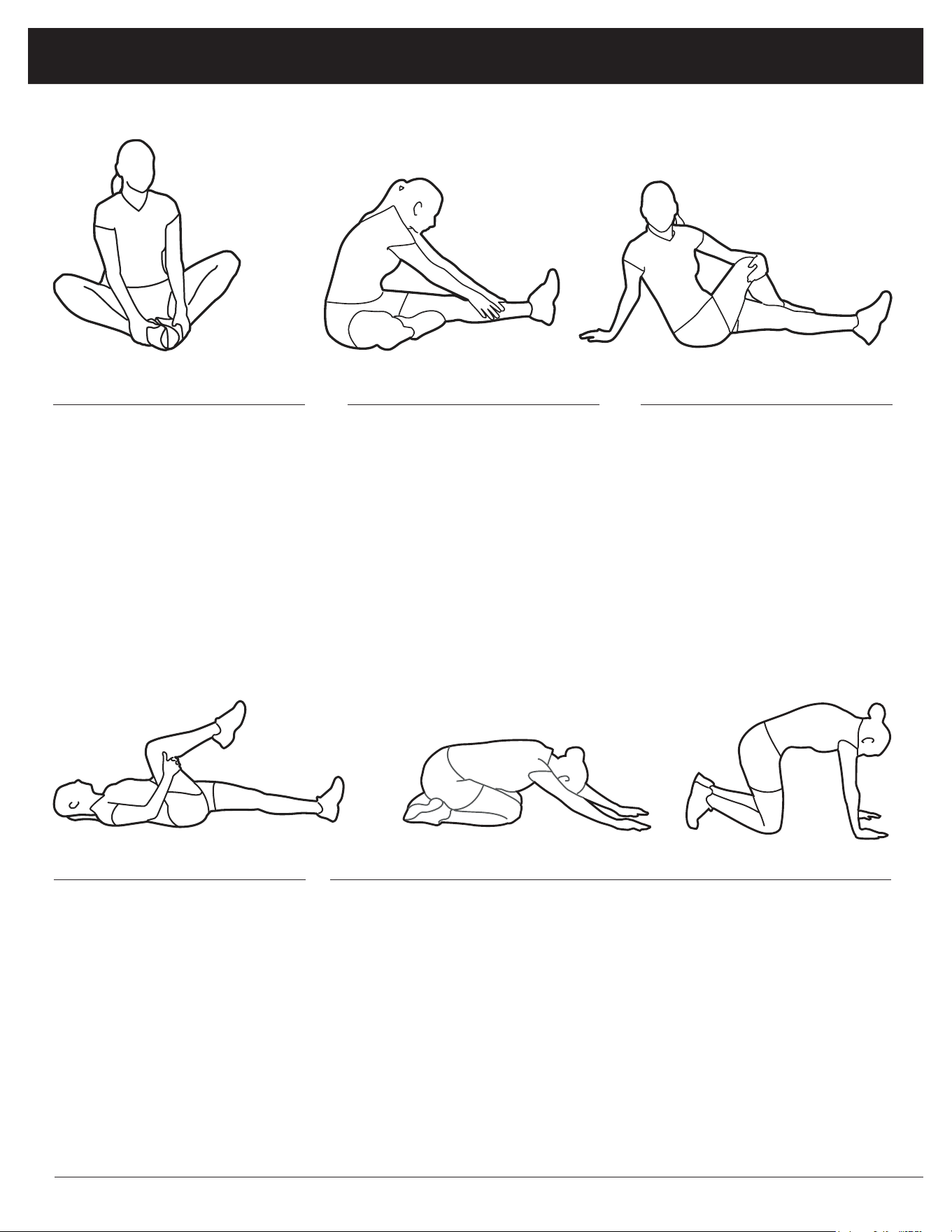
1. Sit with your knees exed and
soles of feet together.
2. Hold your ankles and bend
at your hips (keep your back
straight) as you press your
knees toward the oor with your
elbows.
1. Lie on your back and raise
your right leg as you clasp both
hands under the back of the
knee. Keep your left leg straight.
2. Gently pull your right leg toward
your trunk without
raising your upper body. Switch
leg positions and repeat.
1. Sit with your left leg extended
and bend your right leg at the
knee as you place the sole of
your right foot against the inner
thigh of your extended leg.
2. Flex the foot of your extended
leg (toes pointed toward
ceiling) and gently bend forward
from your hips; keep your back
straight.
3. Reach your hands on your
extended leg as far as possible
and then switch legs and repeat.
1. Assume the depicted position on your hands and knees. Stretch your
hands out in front of you and then slowly start to pull them back in toward
your body as you tuck your chin and arch your back upward.
2. Return to the starting position slowly.
1. Sit with your leg extended and
bend your right knee as you
cross your right leg over your
left leg. Your right foot of your
extended leg foot should be at
on the oor alongside your left
knee.
2. Place your left arm on the
outside of your right leg and pull
against that leg while twisting
your trunk as far as possible to
the right. Place your right hand
on the oor behind your but-
tocks. Reverse leg positions and
repeat.
Groin Stretch
Groin Stretch
Hamstring Stretch
Trunk Flexion, Prone
Trunk Twister
Warm-Up Instructions
BRM 2788/3588
Page 17
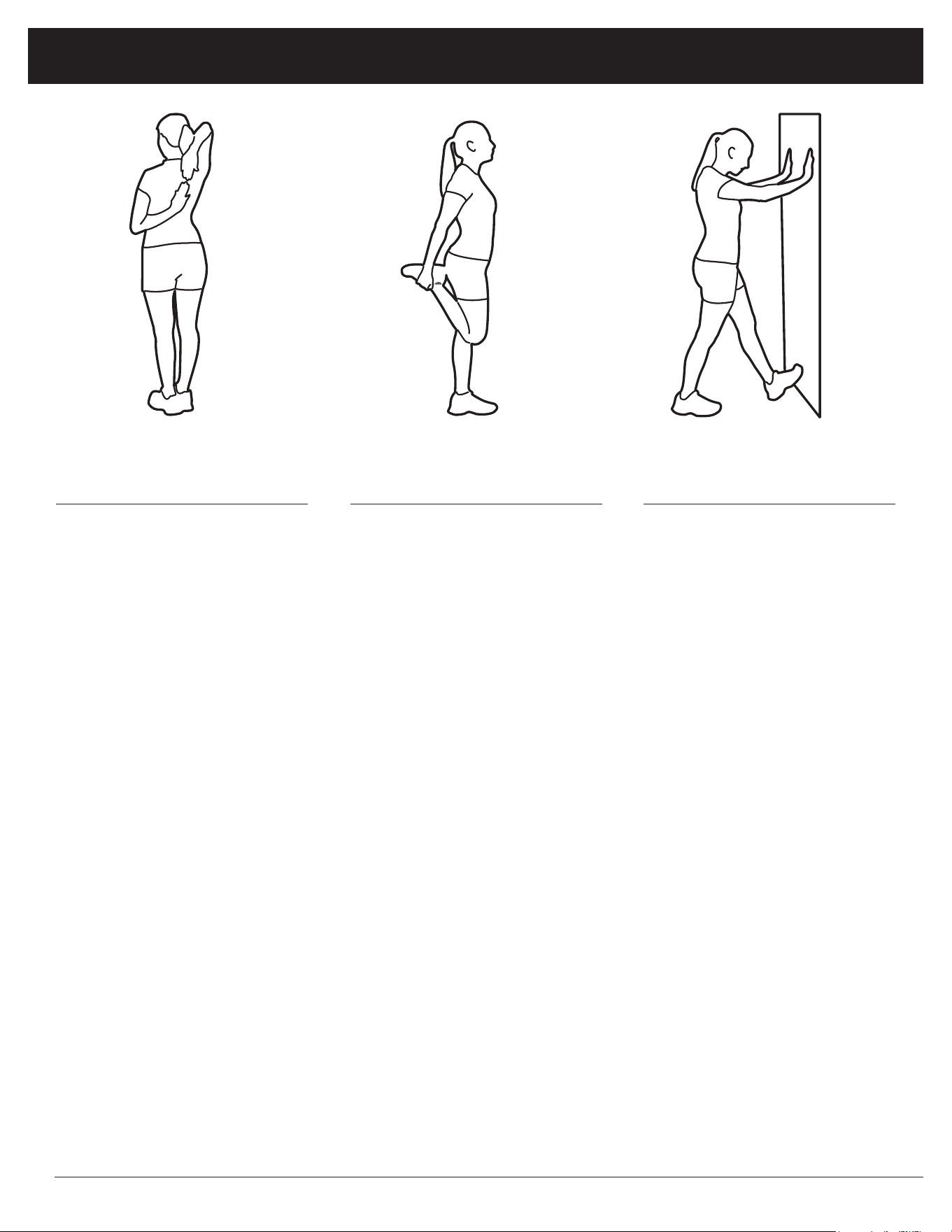
1. Bring your right hand over your
right shoulder to the
upper back and bring your left
hand under your left shoulder to
the upper back.
2. Try to reach your ngertips. If
you are not able to reach your
ngertips, use a towel as an
extension of your hands and
gently pull one hand toward the
other.
Reverse arm positions and
1. Stand on your left leg and hold
onto a support with your left
hand.
2. Flex your right leg behind you,
grasp your ankle or foot with
your right hand and pull your
foot toward your buttocks. Keep
your back straight and right
knee pointed down.
Repeat on the other leg.
1. Place both hands against a wall
to aid your balance. Press the
ball of your left foot against the
wall and keep the heel of the
same foot rested on the oor
(make sure your left knee is
bent).
2. Slowly start to straighten your
left knee and you will feel the
muscles in your left calf stretch.
Switch leg positions and repeat.
Shoulder Stretch Quadriceps Stretch Calf Twister

Proof of purchase
Model Number BRM 2788/3588
BRM 2788/3588
version:01-12-2018
Made in China