Safety Instructions & Warnings
IMPORTANT: Please refer to additional safety instructions and warnings on last page.
- Carefully examine light fixture, wires and all components before and after installation. Ensure there
is no damage or water on any components BEFORE plugging into a GFCI wall outlet.
- NEVER plug in a wet cord. Always unplug with dry hands for any maintenance or service.
- Ensure 12VDC UL® power supply is plugged into a GFCI approved outlet with a drip loop for each
light fixture. If using eFlux pumps, ensure a 24VDC UL® power supply is used with drip loop.
- Turn controller OFF and disconnect lights and pumps from power before performing service.
- Never look directly into the LEDs.
- Never run pumps dry or out of water.
- Follow all safety instructions for any wave pumps or additional add-on accessories.
-
eFlux wave pumps cr
eate a tremendous amount of water flow. Do not install pump where the
strong current can harm corals or animals.
- Pumps can also produce powerful waves in both wave and surge modes. Ensure your aquarium is
designed for wave pumps and ensure pumps are mounted low enough not to push water out of the
aquarium.
- Ensure light fixture is kept clean of any saltwater or salt creep. Fixture is IP65 rated for water
splashing but must be kept clean of water, moisture, salt creep and/or any mineral deposits.
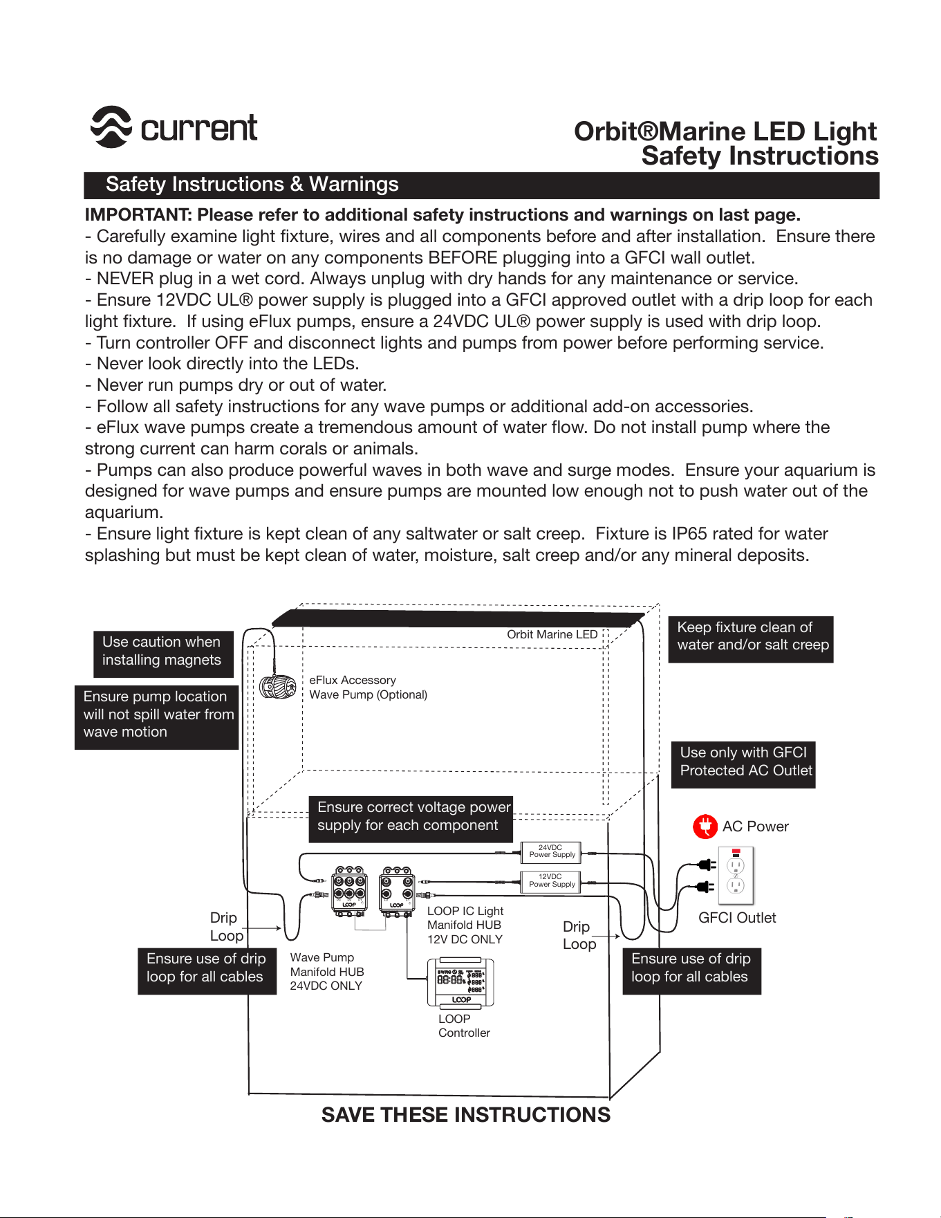
AC Power
GFCI Outlet
12VDC
Power Supply
LOOP
Controller
Wave Pump
Manifold HUB
24VDC ONLY
P1P3
P2
24VDC
Power Supply
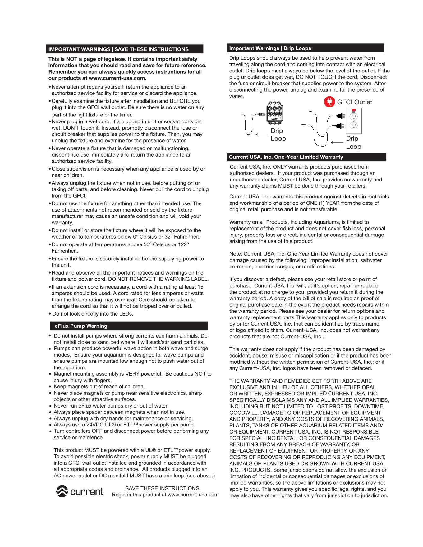
Drip
Loop
Drip
Loop
SAVE THESE INSTRUCTIONS
L1L2
LOOP IC Light
Manifold HUB
12V DC ONLY
Orbit Marine LED
eFlux Accessory
Wave Pump (Optional)
Orbit®Marine LED Light
Safety Instructions
Use caution when
installing magnets
Ensure pump location
will not spill water from
wave motion
Use only with GFCI
Protected AC Outlet
Keep fixture clean of
water and/or salt creep
Ensure use of drip
loop for all cables
Ensure use of drip
loop for all cables
Ensure correct voltage power
supply for each component
1
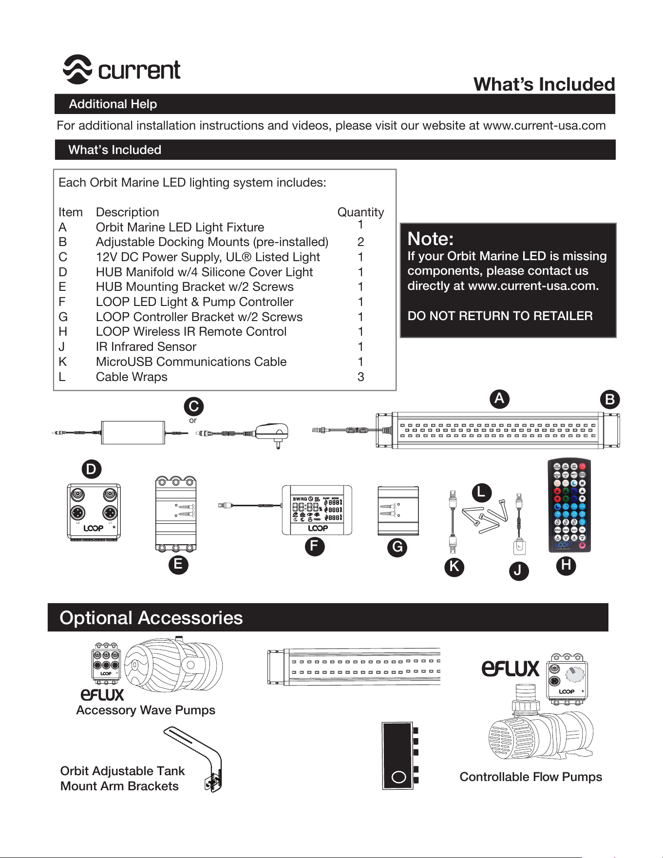
Each Orbit Marine LED lighting system includes:
Item Quantity
A
1
B 2
C 1
D 1
E 1
F 1
G 1
H 1
J 1
K 1
L
Description
Orbit Marine LED Light Fixture
Adjustable Docking Mounts (pre-installed)
12V DC Power Supply, UL® Listed Light
HUB Manifold w/4 Silicone Cover Light
HUB Mounting Bracket w/2 Screws
LOOP LED Light & Pump Controller
LOOP Controller Bracket w/2 Screws
LOOP Wireless IR Remote Control
IR Infrared Sensor
MicroUSB Communications Cable
Cable Wraps
3
Additional Help
"!
or
A
B
C
D
G
L1L2
E
F
K
L
J
H
Note:
If your Orbit Marine LED is missing
components, please contact us
directly at www.current-usa.com.
DO NOT RETURN TO RETAILER
Optional Accessories
Accessory Wave Pumps
Orbit Adjustable Tank
Mount Arm Brackets
Controllable Flow Pumps
What’s Included
What’s Included
For additional installation instructions and videos, please visit our website at www.current-usa.com
Orbit®Marine LED Light
Orbit IC Accessory LED Lights
LOOP Bluetooth
Controller
2
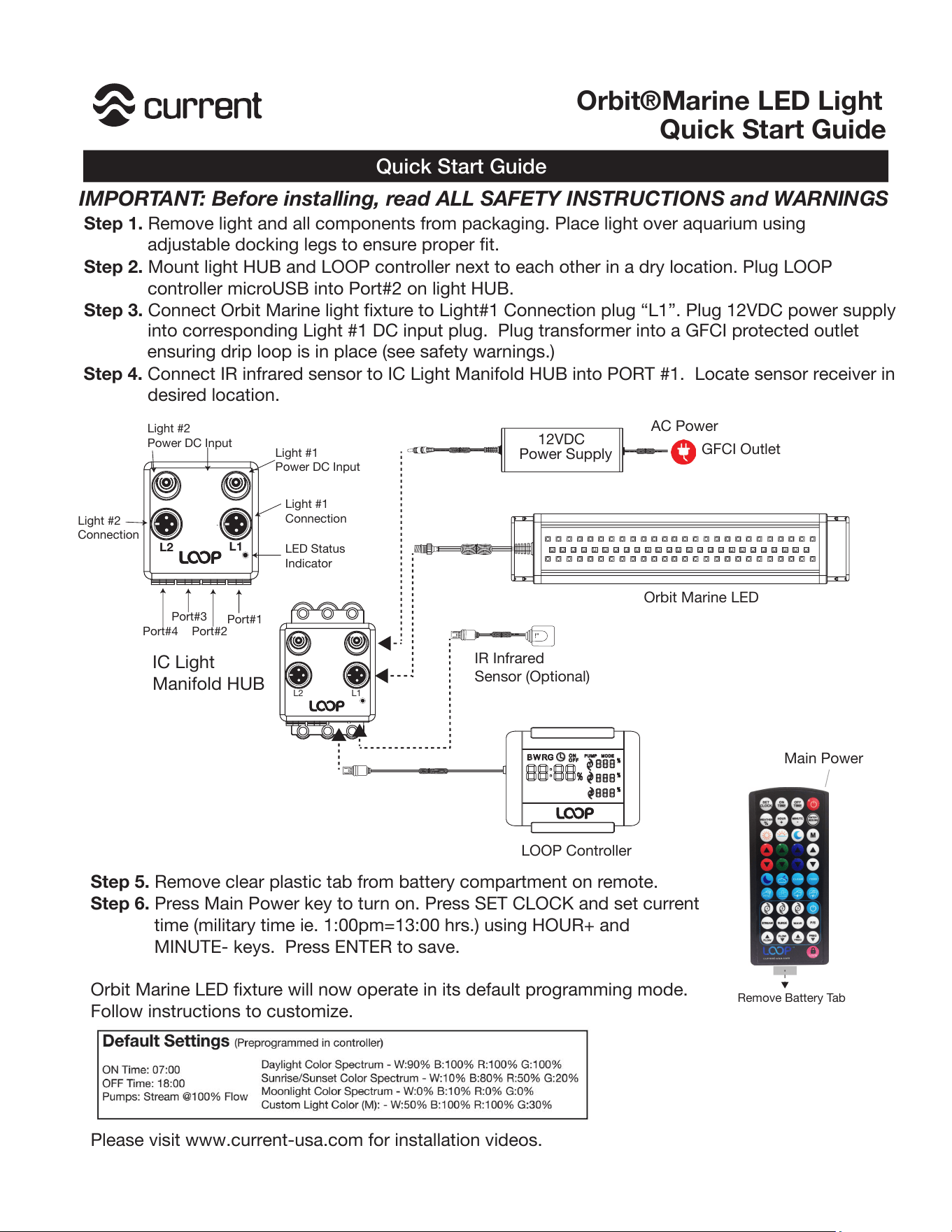
into corresponding Light #1 DC input plug. Plug transformer into a GFCI protected outlet
ensuring drip loop is in place (see safety warnings.)
Step 4. Connect IR infrared sensor to IC Light Manifold HUB into PORT #1. Locate sensor receiver in
desired location.
Quick Start Guide
AC Power
GFCI Outlet
12VDC
Power Supply
Orbit Marine LED
LOOP Controller
IC Light
Manifold HUB
L1L2
Step 5. Remove clear plastic tab from battery compartment on remote.
Step 6. Press Main Power key to turn on. Press SET CLOCK and set current
time (military time ie. 1:00pm=13:00 hrs.) using HOUR+ and
MINUTE- keys. Press ENTER to save.
Orbit Marine LED fixture will now operate in its default programming mode.
Follow instructions to customize.
Please visit www.current-usa.com for installation videos.
!"#
$%&$'
&((
#)*"
&+
#)*"
*
( %&,
( %&,
( - " .
( - " .
! #- "/ * ! 0 - 1 "
23!
4 5
6
7&0-
*)+0#"
,"/#7"-
,/8"
(""9
:;<<=>?@;ABC:DE
F
G
H
I"+#"-
-"!0*"
$%"/+
Remove Battery Tab
IMPORTANT: Before installing, read ALL SAFETY INSTRUCTIONS and WARNINGS
Step 1. Remove light and all components from packaging. Place light over aquarium using
adjustable docking legs to ensure proper fit.
Step 2. Mount light HUB and LOOP controller next to each other in a dry location. Plug LOOP
controller microUSB into Port#2 on light HUB.
Step 3. Connect Orbit Marine light fixture to Light#1 Connection plug “L1”. Plug 12VDC power supply
!"
IR Infrared
Sensor (Optional)
Main Power
L1
L2
Light #1
Power DC Input
Light #2
Power DC Input
Light #1
Connection
Light #2
Connection
LED Status
Indicator
Port#1
Port#2
Port#3
Port#4
Orbit®Marine LED Light
Quick Start Guide
3
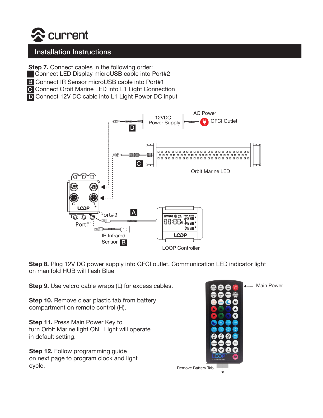
Installation Instructions
Step 7. Connect cables in the following order:
A Connect LED Display microUSB cable into Port#2
b.
Connect IR Sensor microUSB cable into Port#1
c. Connect Orbit Marine LED into L1 Light Connection
d. Connect 12V DC cable into L1 Light Power DC input
Step 8. Plug 12V DC power supply into GFCI outlet. Communication LED indicator light
on manifold HUB will flash Blue.
Step 9. Use velcro cable wraps (L) for excess cables.
Step 10. Remove clear plastic tab from battery
compartment on remote control (H).
Step 11. Press Main Power Key to
turn Orbit Marine light ON. Light will operate
in default setting.
Step 12. Follow programming guide
on next page to program clock and light
cycle.
B
C
D
AC Power
GFCI Outlet
12VDC
Power Supply
Orbit Marine LED
LOOP Controller
L1L2
!"
IR Infrared
Sensor
A
B
C
D
Port#
2
Port#
1
Main Power
Remove Battery Tab
F
F
Orbit®Marine LED Light
4
A
SET
CLOCK
OFF
TIME
ON
TIME
M
FLOW
FLOW
FREQ
FREQ
STREAM
SURGE
P/S
1
2
3
HOUR
MINUTE
WEATHER
WAVE
FEED
current-usa.com
+
_
%
Water Pumps Programming
Dynamic Modes
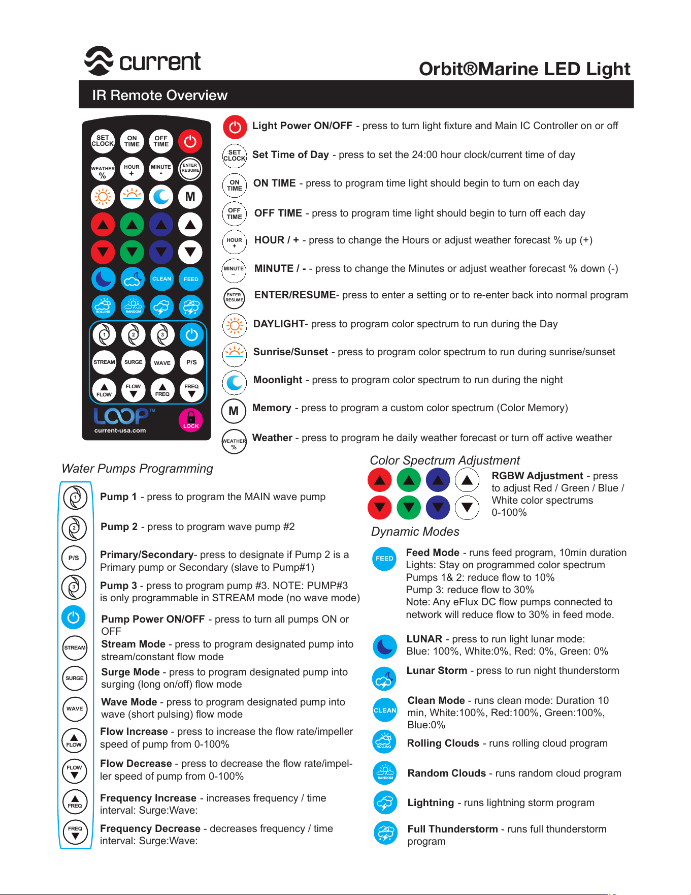
Light Power ON/OFF - press to turn light fixture and Main IC Controller on or off
Set Time of Day
- press to set the 24:00 hour clock/current time of day
ON TIME
- press to program time light should begin to turn on each day
OFF TIME
- press to program time light should begin to turn off each day
HOUR / +
- press to change the Hours or adjust weather forecast % up (+)
MINUTE / -
- press to change the Minutes or adjust weather forecast % down (-)
ENTER/RESUME- press to enter a setting or to re-enter back into normal program
DAYLIGHT- press to program color spectrum to run during the Day
Sunrise/Sunset
- press to program color spectrum to run during sunrise/sunset
Moonlight
- press to program color spectrum to run during the night
Memory
- press to program a custom color spectrum (Color Memory)
Weather - press to program he daily weather forecast or turn off active weather
RGBW Adjustment
- press
to adjust Red / Green / Blue /
White color spectrums
0-100%
Pump 1
- press to program the MAIN wave pump
Pump 2
- press to program wave pump #2
Primary/Secondary- press to designate if Pump 2 is a
Primary pump or Secondary (slave to Pump#1)
Pump 3 - press to program pump #3. NOTE: PUMP#3
is only programmable in STREAM mode (no wave mode)
Pump Power ON/OFF
- press to turn all pumps ON or
OFF
Stream Mode - press to program designated pump into
stream/constant flow mode
Surge Mode - press to program designated pump into
surging (long on/off) flow mode
Wave Mode - press to program designated pump into
wave (short pulsing) flow mode
Flow Increase - press to increase the flow rate/impeller
speed of pump from 0-100%
Flow Decrease - press to decrease the flow rate/impel-
ler speed of pump from 0-100%
Frequency Increase
- increases frequency / time
interval: Surge:Wave:
Frequency Decrease - decreases frequency / time
interval: Surge:Wave:
Feed Mode
- runs feed program, 10min duration
Lights: Stay on programmed color spectrum
Pumps 1& 2: reduce flow to 10%
Pump 3: reduce flow to 30%
Note: Any eFlux DC flow pumps connected to
network will reduce flow to 30% in feed mode.
LUNAR
- press to run light lunar mode:
Blue: 100%, White:0%, Red: 0%, Green: 0%
Lunar Storm - press to run night thunderstorm
Clean Mode - runs clean mode: Duration 10
min, White:100%, Red:100%, Green:100%,
Blue:0%
Rolling Clouds
- runs rolling cloud program
Random Clouds - runs random cloud program
Lightning
- runs lightning storm program
Full Thunderstorm - runs full thunderstorm
program
Color Spectrum Adjustment
ENTER
RESUME
CLEAN
SET
CLOCK
OFF
TIME
ON
TIME
M
FLOW
FLOW
FREQ
FREQ
STREAM SURGE
P/S
1 2
3
HOUR
MINUTE
WAVE
current-usa.com
+
-
%
%
ENTER
RESUME
WEATHER
%
TM
FEED
CLEAN
LOCK
IR Remote Overview
Orbit®Marine LED Light
Marine LED Light
5
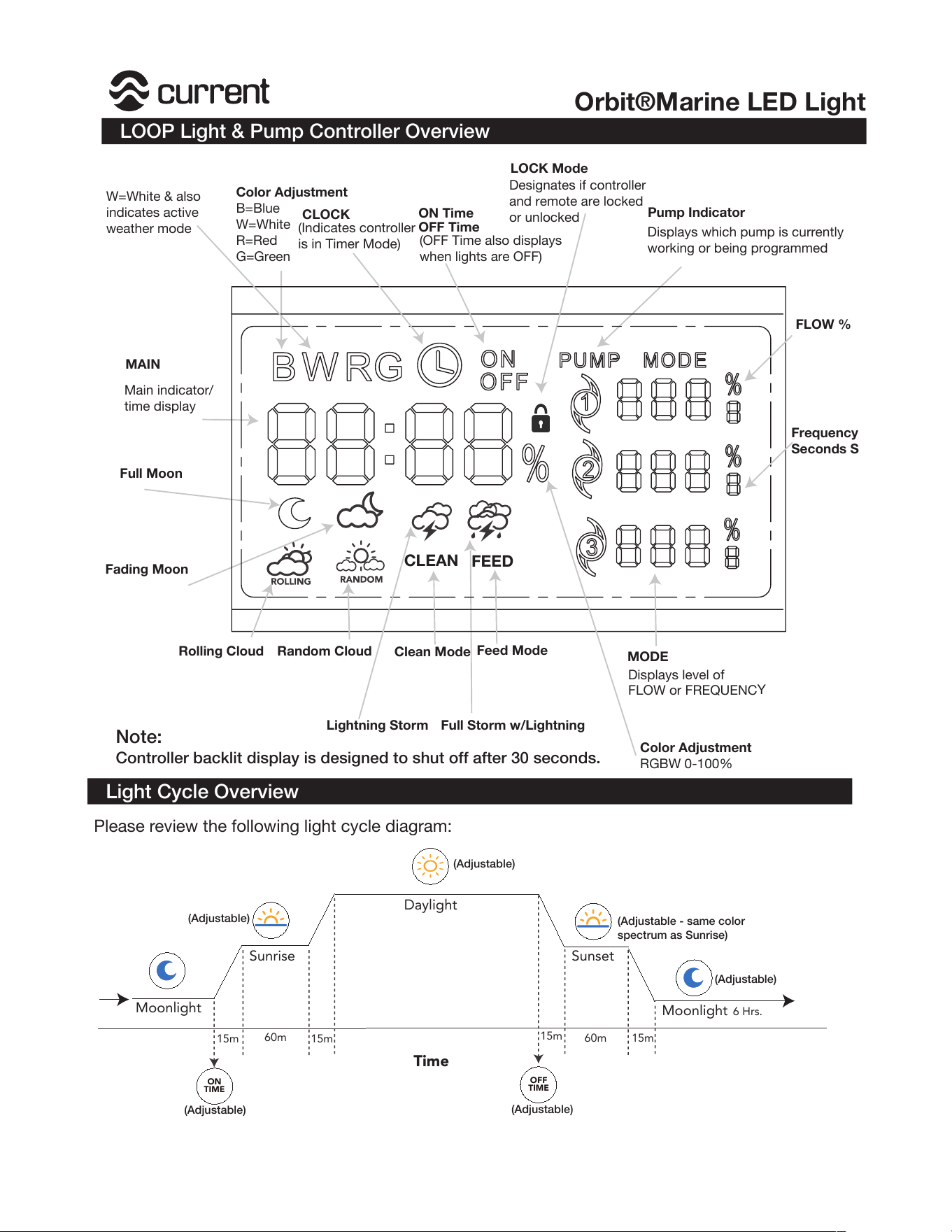
LOOP Light & Pump Controller Overview
Orbit®Marine LED Light
MODE
Pump Indicator
LOCK Mode
CLEAN
Color Adjustment
B=Blue
W=White
R=Red
G=Green
Displays which pump is currently
working or being programmed
Displays level of
FLOW or FREQUENC
Y
Designates if controller
and remote are locked
or unlocked
MAIN
Main indicator/
time display
FEED
CLOCK
ON Time
OFF Time
Full Moon
Fading Moon
Rolling Cloud Random Cloud
Full Storm w/LightningLightning Storm
Clean Mode
Feed Mode
Note:
Controller backlit display is designed to shut off after 30 seconds.
W=White & also
indicates active
weather mode
FLOW %
Frequency
Seconds S
Color Adjustment
RGBW 0-100%
(OFF Time also displays
when lights are OFF)
(Indicates controller
is in Timer Mode)
Light Cycle Overview
Moonlight
Time
15m
15m
15m
15m60m
60m
Moonlight
Sunrise
Daylight
Sunset
ON
TIME
OFF
TIME
6 Hrs.
Please review the following light cycle diagram:
(Adjustable)
(Adjustable)
(Adjustable)
(Adjustable)
(Adjustable)
(Adjustable - same color
spectrum as Sunrise)
6
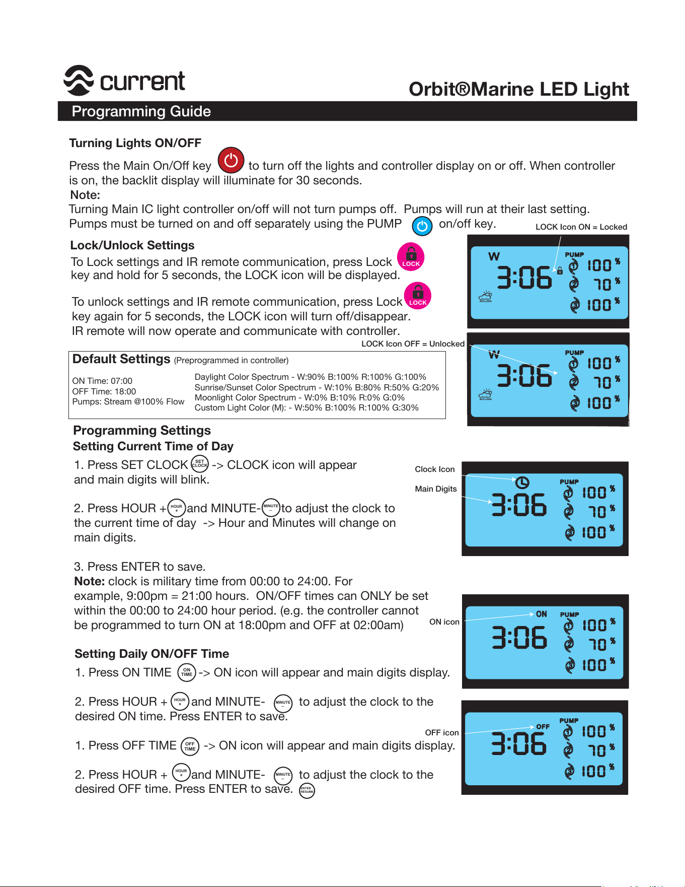
Turning Lights ON/OFF
Press the Main On/Off key to turn off the lights and controller display on or off. When controller
is on, the backlit display will illuminate for 30 seconds.
Lock/Unlock Settings
To Lock settings and IR remote communication, press Lock
key and hold for 5 seconds, the LOCK icon will be displayed.
To unlock settings and IR remote communication, press Lock
key again for 5 seconds, the LOCK icon will turn off/disappear.
IR remote will now operate and communicate with controller.
Setting Current Time of Day
Programming Settings
LOCK
LOCK
LOCK Icon ON = Locked
LOCK Icon OFF = Unlocked
2334
Turning Main IC light controller on/off will not turn pumps off. Pumps will run at their last setting.
Pumps must be turned on and off separately using the PUMP on/off key.
Note:
1. Press SET CLOCK -> CLOCK icon will appear
and main digits will blink.
2. Pr
ess HOUR + and MINUTE- to adjust the clock to
the current time of day -> Hour and Minutes will change on
main digits.
3. Press ENTER to save.
Note: clock is military time from 00:00 to 24:00. For
example, 9:00pm = 21:00 hours. ON/OFF times can ONLY be set
within the 00:00 to 24:00 hour period. (e.g. the controller cannot
be programmed to turn ON at 18:00pm and OFF at 02:00am)
1. Pr
ess ON TIME -> ON icon will appear and main digits display.
2. Press HOUR + and MINUTE- to adjust the clock to the
desir
ed ON time. Press ENTER to save.
1. Press OFF TIME -> ON icon will appear and main digits display.
2. Press HOUR + and MINUTE- to adjust the clock to the
desir
ed OFF time. Press ENTER to save.
Setting Daily ON/OFF Time
SET
CLOCK
HOUR
MINUTE
+
_
OFF
TIME
ON
TIME
ENTER
RESUME
HOUR
MINUTE
+
_
HOUR
MINUTE
+
_
Clock Icon
Main Digits
ON icon
OFF icon
Programming Guide
Orbit®Marine LED Light
Default Settings (Preprogrammed in controller)
ON Time: 07:00
OFF Time: 18:00
Pumps: Stream @100% Flow
Daylight Color Spectrum - W:90% B:100% R:100% G:100%
Sunrise/Sunset Color Spectrum - W:10% B:80% R:50% G:20%
Moonlight Color Spectrum - W:0% B:10% R:0% G:0%
Custom Light Color (M): - W:50% B:100% R:100% G:30%
7
Programming Daily Weather Patterns
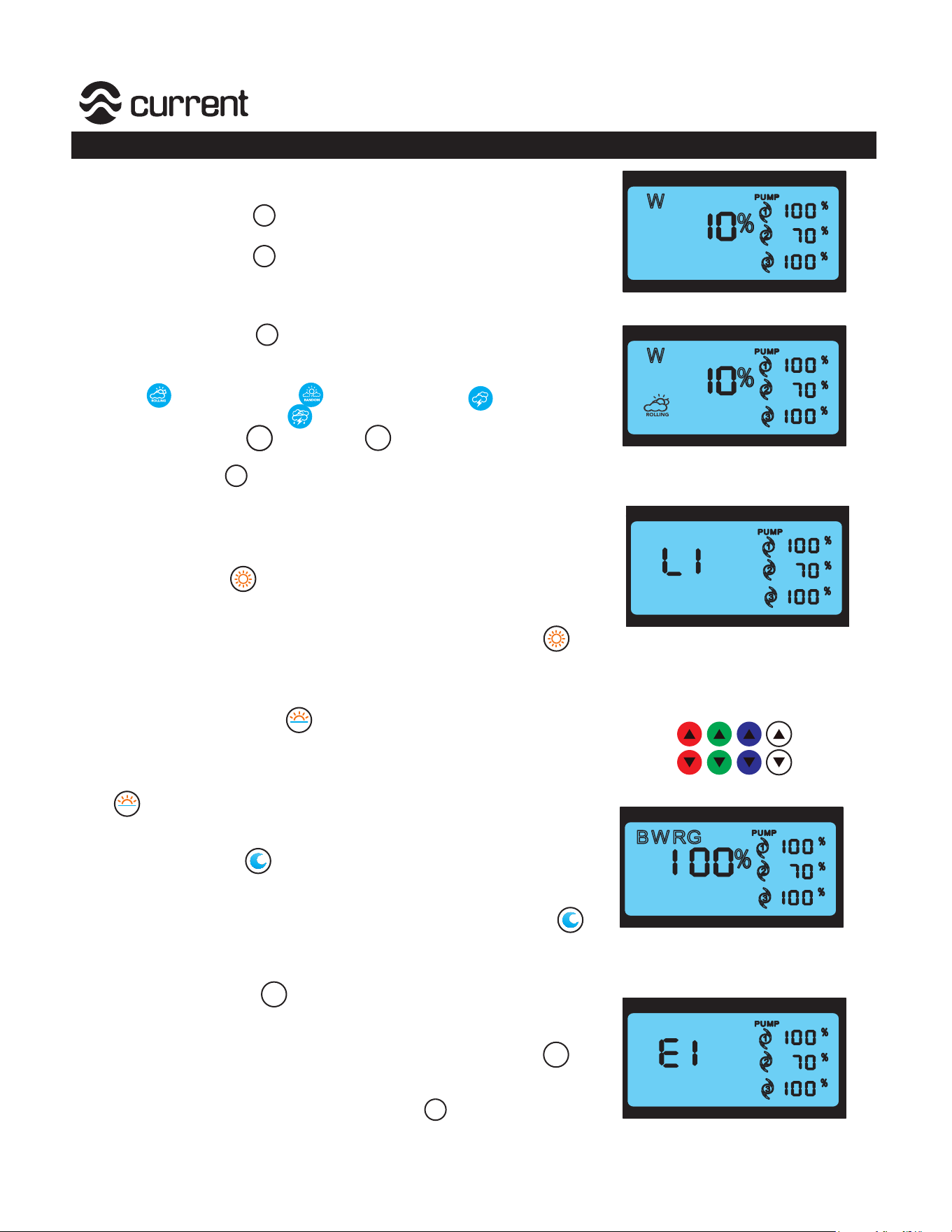
To turn Daily Weather ON/OFF
1. Press Weather % and hold for 5 seconds, “W” will
appear on display indicator daily weather is turned on.
2. Press Weather % and hold for 5 seconds to turn
off, “W” will disappear from display.
To Program Daily Weather
1. Press Weather % and hold for 5 seconds, “W”
will appear on display indicator daily weather is turned on.
2. Press Weather pattern desired, choose either Rolling
Cloud ,Random Cloud , Lightning Storm or
Full Storm with Lightning .
3. Press the Hour +
or Minute - to change forecast
from 10% to 50%.
4.
Press ENTER , weather is now pr
ogrammed and
will run during Daytime.
Programming Daylight Color Spectrum
1. Pr
ess Daylight , L1 will appear on display. Adjust
color by pressing Red, Green, White and Blue arrow keys. The
R,G,B,W and % intensity will appear on main display.
2. Once desired color spectrum is acheived, press Daylight
for 5 seconds, E1 will display
, indicating spectrum is saved.
Programming Sunrise & Sunset Color Spectrums
1.
Press Sunrise/Sunset , L2 will appear on display. Adjust
color by pr
essing Red, Green, White and Blue arrow keys. The
R,G,B,W and % intensity will appear on main display.
2. Once desired color spectrum is acheived, press Sunrise/Sunset
for 5 seconds, E2 will display
, indicating spectrum is saved.
Programming Moonlight Color Spectrum
1. Press Moonlight , L3 will appear on display. Adjust
color by pressing Red, Green, White and Blue arrow keys. The
R,G,B,W and % intensity will appear on main display.
2. Once desired color spectrum is acheived, press Moonlight
for 5 seconds, E3 will display
, indicating spectrum is saved.
Programming Custom Color Spectrum
1. Press M (Memory) , L4 will appear on display. Adjust
color by pressing Red, Gr
een, White and Blue arrow keys. The
R,G,B,W and % intensity will appear on main display.
2. Once desired color spectrum is acheived, press Memory
for 5 seconds, E4 will display
, indicating spectrum is saved.
M
MINUTE
HOUR
+
WEATHER
%
.
%
WEATHER
-
ENTER
RESUME
M
WEATHER
%
NOTE: You MUST press ENTER/RESUME to put controller
back into timer mode.
ENTER
RESUME
Color Adjustment - Press to
adjust Red/Green/Blue/White
color spectrums 0-100%
Programming Guide
Orbit®Marine LED Light
8
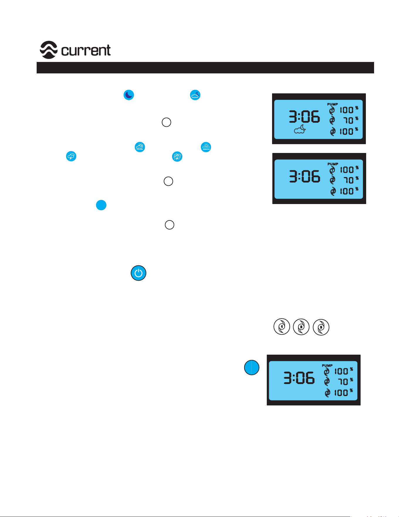
On Demand Dynamic Modes
Moonlight Modes
1. Press either Full Moon or Fading Moon to
activate on-demand moonlight. Pr
ogram will run 30 minutes,
then resume into normal programming.
2. To exit On-Demand program, pr
ess .
Weather Modes
1. Press either Rolling Cloud ,Random Cloud , Lightning
Storm , or Full Storm with Lightning toactivate on-demand
weather
. Program will run 30 minutes, then resume into normal
programming.
2. To exit On-Demand program, pr
ess .
CLEAN Mode
1. Pr
ess CLEAN to activate color spectrum for cleaning tank.
Program will run 10 minutes, then resume into normal programming.
2. To exit On-Demand program, pr
ess .
ENTER
RESUME
ENTER
RESUME
ENTER
RESUME
CLEAN
CLEAN
PUMP Programming
Turning all pumps on/off
Press the Main On/Off key to turn all of the pumps and pump display on or off. When pump
and lights are on, LEDs on display will illuminate. If all pumps are turned off, all LEDs on display will
be off.
Turning individual pumps on/off
To individually turn each pump on or off, hold the designated Pump Key for 5
seconds. Pump will turn on or off.
FEED Mode
To set all pumps into feeding mode, press the FEED Mode key .
Wave Pumps 1&2 within the LOOP network will go into idle speed for
10 minutes. After 10 minutes, the pumps will ramp back into their
previously programmed flow mode. LED rate display will blink on/off
during FEED Mode.
Flow Pump #3 and any additional Flow Pumps within the network
will ramp down to a 30% stream flow rate speed for 10 minutes. After
10 minutes, the pumps will ramp back into their previously programmed
flow mode.
,
-
.
FEED
FEED
Programming Guide
Orbit®Marine LED Light
9
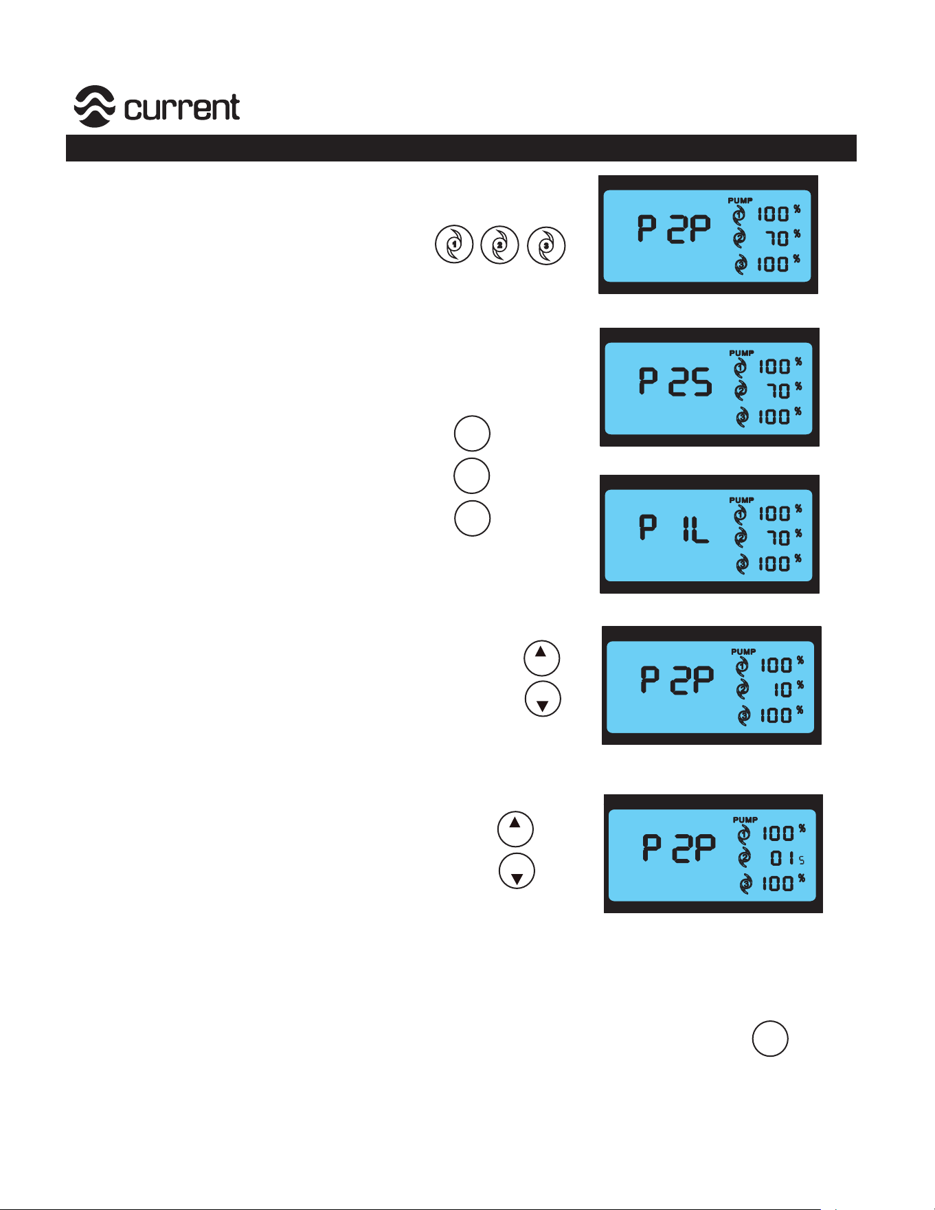
eFlux Wave Pump Programming
Step 1: Designate pump to program (1, 2, or 3)
Press the pump you desire to program by
pressing the designated pump key.
Pump icon will illuminate and blink on display.
Step 2: Program water flow mode
Press the FLOW mode you wish to run the pump
in by pressing the designated flow key.
Main display will illuminate as follows:
P = Pump
1,2,3 = Indicates Pump # being programmed
P = Pulse/Wave Mode
L = Stream Mode
S = Surge Mode
For Example - P1L = Pump #1 in Stream Mode
Program the maximum FLOW
Press the increase/decrease FLOW keys to adjust
the pumps maximum flow rate until you have reached
the desired flow. Flow rate will illuminate on the display.
The RATE display will show the flow from 0-100% in
1% flow increments.
Designate FREQUENCY setting
If programming the pump in either SURGE or WAVE
mode, adjust the FREQUENCY setting by pressing
the increase/decrease FREQ keys until the desired
frequency/duration is reach.
The frequency will show in seconds.
!
"
#
STREAM
SURGE
WAVE
FLOW
FLOW
FREQ
FREQ
Note: Decreasing FREQUENCY shortens the time duration between min/max flow. It will appear
opposite in your aquarium (lowing frequency/duration will increase wave motion).
Your setting will automatically be saved into memory after 10 seconds.
No keys need to be set to save your settings. You can also press ENTER
ENTER
RESUME
P2P = Pump # 2, Wave/Pulse Mode, 70% Flow
P2P = Pump # 2, Wave/Pulse Mode, 10% Flow
P2S = Pump # 2, Surge Mode, 70% Flow
P1L = Pump # 1, STREAM Mode, 100% Flow
P2P = Pump # 2, Wave/Pulse Mode, 0.1 Seconds
Programming Guide
Orbit®Marine LED Light
10
-
-
-
-
-
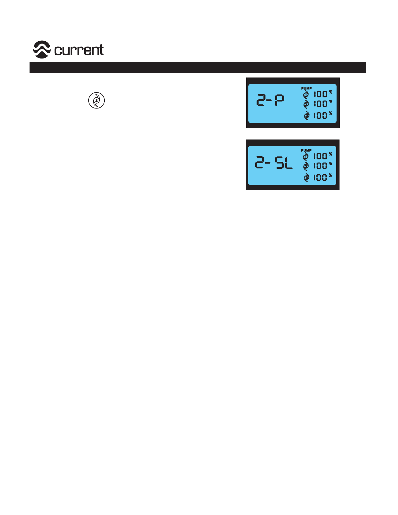
Designating Primary/Secondary Pump
Press pump #2
Press P/S for 5 seconds to designate Pump #2
as a Primary Pump or Secondary (Slave) Pump:
P = Primary (runs on its own program)
S = Secondary (slave), runs opposite of Pump #1
Display will read as Follows:
2-P = Pump#2 Primary
2-SL= Pump#2 Secondary
!
Programming Guide
Orbit®Marine LED Light
11
D
C
Current USA, Inc. ONLY warrants products purchased from
authorized dealers. If your product was purchased through an
unauthorized dealer, Current-USA, Inc. provides no warranty and
any warranty claims MUST be done through your retailers.
GFCI Outlet
Drip
Loop
P1P3
P2
Drip
Loop
eFlux Pump Warning
Do not install pumps where strong currents can harm animals. Do
not install close to sand bed where it will suck/stir sand particles.
Pumps can produce powerful wave action in both wave and surge
modes. Ensure your aquarium is designed for wave pumps and
ensure pumps are mounted low enough not to push water out of
the aquarium.
Magnet mounting assembly is VERY powerful. Be cautious NOT to
cause injury with fingers.
Keep magnets out of reach of children.
Never place magnets or pump near sensitive electronics, sharp
objects or other attractive surfaces.
Never run eFlux water pumps dry or out of water
Always place spacer between magnets when not in use.
Always unplug with dry hands for maintenance or servicing.
Always use a 24VDC UL® or ETL™power supply per pump.
Turn controllers OFF and disconnect power before performing any
service or maintence.
This product MUST be powered with a UL® or ETL™power supply.
To avoid possible electric shock, power supply MUST be plugged
into a GFCI wall outlet installed and grounded in accordance with
all appropriate codes and ordinance. All products plugged into an
AC power outlet or DC manifold MUST have a drip loop (see above.)
SAVE THESE INSTRUCTIONS.
Register this product at www.current-usa.com
12